zubehör für trommelbremsen options for drum brakesmedia!file!products!czesci... · wn 200/22...
TRANSCRIPT
Zubehör für TrommelbremsenOptions for Drum Brakes
Zubehör Trommelbremsen.indd 1Zubehör Trommelbremsen.indd 1 23.12.2004 13:41:46 Uhr23.12.2004 13:41:46 Uhr
Technische BeschreibungTechnical Description
Als Zubehör für Trommelbremsen sind erhältlich· Bremstrommeln
· Elastische Kupplungen mit Bremstrommel
· Zahnkupplungen mit Bremstrommel
· Mechansiche und induktive Endschalter zur Anzeige
- Bremse auf - Bremse zu
- Belagverschleiß - Handlüftposition
· Belagverschleißnachstellung
· Schutzhauben
· Bremsbacken
· Bremsbeläge
· Elektro-hydraulische Lüftgeräte
· Pneumatikzylinder
· Hydraulikzylinder
· Hand- und Notlüftungen
· SMS- Status Monitoring System
Drum brake options available· Brake drums
· Flexible couplings with brake drums
· Gear couplings with brake drums
· Mechanical and inductive type switches for indication
- Brake released
- Brake applied
- Pad wear
- Manual release position
· Lining wear compensators
· Housings
· Brake shoes
· Brake linings
· Electro-hydraulic thrustors
· Pneumatic cylinders
· Hydraulic cylinders
· Manual- and emergency release devices
· SMS- Status Monitoring System
Siegerland Bremsen Emde GmbH & Co. KG · Auf der Stücke 1-5 · D-35708 HaigerTelefon 0 27 73 94 00 – 0 · Telefax 0 27 73 94 00 – 10 · E-Mail [email protected] · www.sibre.de
Zubehör Trommelbremsen.indd 2Zubehör Trommelbremsen.indd 2 23.12.2004 13:41:51 Uhr23.12.2004 13:41:51 Uhr
M 1501 1012 E-DE-ENSeite / page 1/1
11.2007
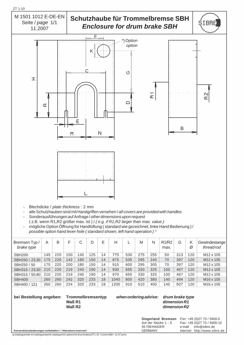
Schutzhaube für Trommelbremse SBHEnclosure for drum brake SBH
B1 / B2 *)
ZT 1-10
Siegerland Bremsen Fon: +49 (0)27 73 / 9400-0Auf der Stücke 1 - 5 Fax: +49 (0)27 73 / 9400-1035 708 HAIGER e-mail: [email protected] internet: http://www.sibre.de
g:\catalogues\de-en catalogues\pmd-catalogue\10 options for drum brakes\ZT1-10 Covers SBH 11-07.pmd
Konstruktionsänderungen vorbehalten ! / Alterations reserved !
SBH200SBH250 / 23;30SBH250 / 50SBH315 / 23;30SBH315 / 50;80SBH400SBH400 / 121
220220220220220260260
255240305325325380400
275295295330330420510
530535600655655800910
775875915930970
10401200
14141414141818
140180180240240320320
125150150190190233233
150142200219219242224
145175175210210260260
Bremsen Typ /brake type
A B F C D E H L M N R1/R2max.
507070
100100140140
120120120120120120120
G
313397397467467494507
KØ
Gewindestangethread rod
M12 x 105M12 x 105M12 x 105M12 x 105M12 x 105M16 x 105M16 x 105
bei Bestellung angeben: Trommelbremsentyp when ordering advise: drum brake typeMaß R1 dimension R1Maß R2 dimension R2
- Blechdicke / plate thickness : 2 mm- alle Schutzhauben sind mit Handgriffen versehen / all covers are provided with handles- Sonderausführungen auf Anfrage / other dimensions upon request
( z.B. wenn R1,R2 größer max. ist ) / ( e.g. if R1,R2 larger than max. value )- mögliche Option Öffnung für Handlüftung ( standard wie gezeichnet, linke Hand Bedienung ) /
possible option hand lever hole ( standard shown, left hand operation ) *)
K
F
G
*) Option option
B
C
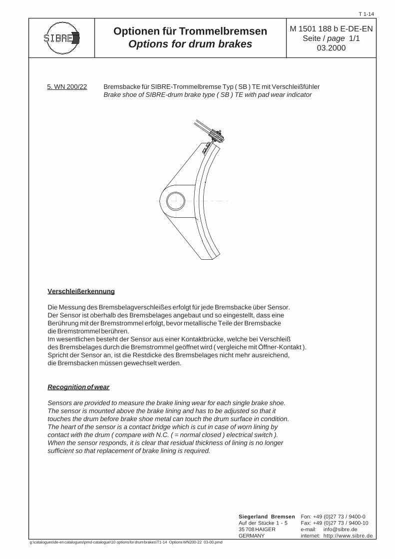
Verschleißerkennung
Die Messung des Bremsbelagverschleißes erfolgt für jede Bremsbacke über Sensor.Der Sensor ist oberhalb des Bremsbelages angebaut und so eingestellt, dass eineBerührung mit der Bremstrommel erfolgt, bevor metallische Teile der Bremsbackedie Bremstrommel berühren.Im wesentlichen besteht der Sensor aus einer Kontaktbrücke, welche bei Verschleißdes Bremsbelages durch die Bremstrommel geöffnet wird ( vergleiche mit Öffner-Kontakt ).Spricht der Sensor an, ist die Restdicke des Bremsbelages nicht mehr ausreichend,die Bremsbacken müssen gewechselt werden.
Recognition of wear
Sensors are provided to measure the brake lining wear for each single brake shoe.The sensor is mounted above the brake lining and has to be adjusted so that ittouches the drum before brake shoe metal can touch the drum surface in condition.The heart of the sensor is a contact bridge which is cut in case of worn lining bycontact with the drum ( compare with N.C. ( = normal closed ) electrical switch ).When the sensor responds, it is clear that residual thickness of lining is no longersufficient so that replacement of brake lining is required.
5. WN 200/22 Bremsbacke für SIBRE-Trommelbremse Typ ( SB ) TE mit VerschleißfühlerBrake shoe of SIBRE-drum brake type ( SB ) TE with pad wear indicator
M 1501 188 b E-DE-ENSeite / page 1/1
03.2000
Optionen für TrommelbremsenOptions for drum brakes
T 1-14
Siegerland Bremsen Fon: +49 (0)27 73 / 9400-0Auf der Stücke 1 - 5 Fax: +49 (0)27 73 / 9400-1035 708 HAIGER e-mail: [email protected] internet: http://www.sibre.de
g:\catalogues\de-en catalogues\pmd-catalogue\10 options for drum brakes\T1-14 Options WN200-22 03-00.pmd
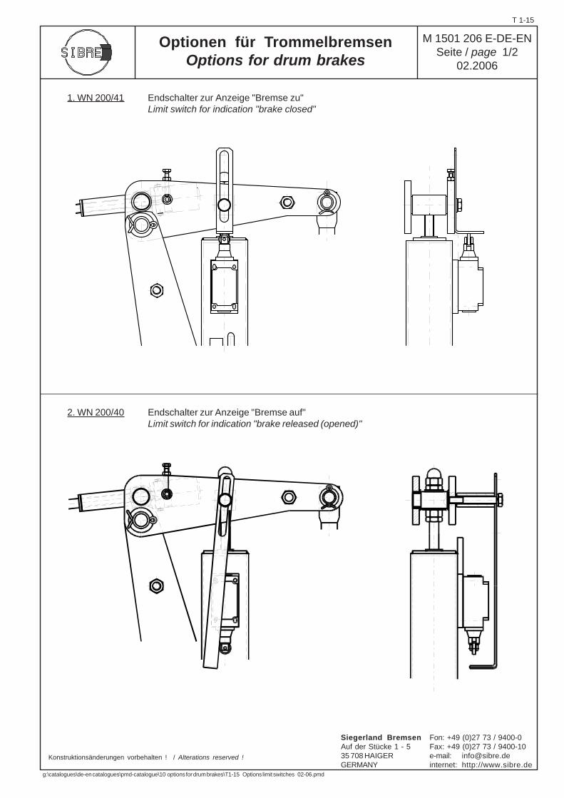
Optionen für TrommelbremsenOptions for drum brakes
1. WN 200/41 Endschalter zur Anzeige "Bremse zu"Limit switch for indication "brake closed"
2. WN 200/40 Endschalter zur Anzeige "Bremse auf"Limit switch for indication "brake released (opened)"
Konstruktionsänderungen vorbehalten ! / Alterations reserved !
M 1501 206 E-DE-ENSeite / page 1/2
02.2006
T 1-15
Siegerland Bremsen Fon: +49 (0)27 73 / 9400-0Auf der Stücke 1 - 5 Fax: +49 (0)27 73 / 9400-1035 708 HAIGER e-mail: [email protected] internet: http://www.sibre.de
g:\catalogues\de-en catalogues\pmd-catalogue\10 options for drum brakes\T1-15 Options limit switches 02-06.pmd
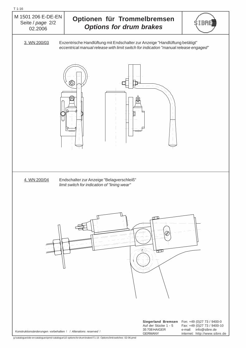
3. WN 200/03 Exzentrische Handlüftung mit Endschalter zur Anzeige "Handlüftung betätigt"eccentrical manual release with limit switch for indication "manual release engaged"
4. WN 200/04 Endschalter zur Anzeige "Belagverschleiß"limit switch for indication of "lining wear"
Optionen für TrommelbremsenOptions for drum brakes
Konstruktionsänderungen vorbehalten ! / Alterations reserved !
M 1501 206 E-DE-ENSeite / page 2/2
02.2006
T 1-16
Siegerland Bremsen Fon: +49 (0)27 73 / 9400-0Auf der Stücke 1 - 5 Fax: +49 (0)27 73 / 9400-1035 708 HAIGER e-mail: [email protected] internet: http://www.sibre.de
g:\catalogues\de-en catalogues\pmd-catalogue\10 options for drum brakes\T1-15 Options limit switches 02-06.pmd
The purpose of this device is to compensate for thewear of brake linings.With correct adjustment, the wear compensator willmaintain an almost constant reserve stroke.
Inspection of reserve stroke is necessary even with acorrect adjustment of wear compensator, especiallyduring commissioning and the inital time of commercialoperation.
Mode of Operationassumption: the wear compensator is correctly
adjusted according to our manual.
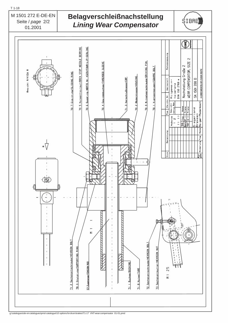
When opening and closing the brake, the position of thedrive pin ( 70.9 ) remains unchanged, until the reservestroke of the thruster is reduced due to the wear of thelinings. Upon decrease of reserve stroke, the adjustingbolt ( 72 ) will contact the drive pin ( 70.9 ) when closingthe brake. The drive pin is rotated counter clock-wise bya certain angle. The sliding ring ( 70.7 ) is rotated by thesame degree as the drive pin. The threaded sleeve( 70.4 ) does not move because the back stop needlebearing ( 70.5 ) is rotating free in counter clock-wisedirection.
With the subsequent release of the brake, the edge of thedrive pin drilling will contact and rotate the drive pin andthe sliding ring in clock-wise direction. When rotatedclock-wise, the back stop needle bearing is locked andtransfers the rotation onto the threaded sleeve.When rotating the threaded sleeve, the tension rod ( 57 )is screwed into the wear compensator, reducing thedistance between the two brake arms, ergo between thelining surfaces. Thus, the reserve stroke is increased.Depending on the amount of wear per brake application,the wear compensator may need several operating cycles,until the initial reserve stroke level is reached agina.At this point, the drive pin will touch the adjusting bolt andthe drillig for drive pin respectively when opening andclosing the brake, however, there is not further rotation ofthe drive pin.
If the initial reserve stroke level should not be reachedagain, a re-adjustment of wear compensator is required.If the reserve stroke level should be continuously reducedin spite of having re-adjusted the wear compensator, thewear rate per stop exceeds the compensating capacity ofthe wear compensator and an additional manual wearcompensation is required.
The quadring seals ( 70.6 ) avoid any dust or dirt to enterinto the system and they generate sufficient friction toprotect the device from vibrations.
BelagverschleißnachstellungLining Wear Compensator
M 1501 272 E-DE-ENSeite / page 1/2
01.2001
Die Nachstellvorrichtung dient zum Ausgleich desBelagverschleiß und gewährleistet bei korrekterEinstellung einen nahezu konstantenResthub am Lüftgerät.
Eine Kontrolle des Resthubes ist auch beikorrekter Einstellung insbesondere während undkurz nach der Inbetriebnahmephase unumgänglich.
FunktionsprinzipVoraussetzung: die Nachstellvorrichtung wurde
gemäß Anleitung justiert.
Die Position der Mitnehmerschraube ( 70.9 ) bleibtbeim öffnen und schließen der Bremse solangeunverändert, bis der Resthub aufgrund desBelagverschleißes abnimmt.In diesem Fall wird die Mitnehmerschraube ( 70.9 )beim schließen der Bremse durch die Stellschraube( 72 ) um einen bestimmten Winkel entgegen demUhrzeigersinn gedreht.Entsprechend dem Drehwinkel der Mitnehmerschraubedreht der Gleitring ( 70.7 ) auf dem Hülsenfreilauf ( 70.5 ),ohne das die Gewindebuchse ( 70.4 ) gedreht wird.
Beim nächsten Lüfthub wird die Mitnehmerschraubedurch die Berührung mit der Mitnehmerbohrung imUhrzeigersinn gedreht. Durch den Hülsenfreilauf,der in dieser Drehrichtung blockiert, wird dieDrehbewegung auf die Gewindehülse übertragen,die somit ebenfalls im Uhrzeigersinn dreht.Die Gewindespindel ( 57 ) wird beim drehen derGewindebuchse in das Gehäuse derNachstellvorrichtung hineingezogen, so dass derAbstand zwischen den beiden Bremshebeln und damitauch zwischen den Bremsbelagflächen verringert wird.Hierdurch steigt der Resthub wieder an.Je nach Abrieb pro Bremsung an den Belagflächenwerden mehrere Schaltspiele benötigt, bis derursprünglich eingestellte Resthub wieder erreicht ist.Nach Erreichen des ursprünglich eingestelltenResthubes wird die Mitnehmerschraube beim öffnenund schließen der Bremse zwar durch die Stellschraubebeziehungsweise die Mitnehmerbohrung berührt, eineDrehbewegung wird hierdurch jedoch nicht ausgelöst.
Sollte der ursprünglich eingestellte Resthub nicht wiedererreicht werden, so ist eine Korrektur der Justierung derNachstellung vorzunehmen. Sollte der Resthub dennochimmer wieder unterschritten werden, so übersteigt derAbrieb je Bremsung die Nachstellkapazität derNachstellvorrichtung und ein zusätzlicher manuellerVerschleißausgleich ist erforderlich.
Durch die eingebauten Quadringe ( 70.6 ) wird dieNachstellvorrichtung einerseits gegen das Eindringenvon Schmutz und Staub geschützt, andererseits wirdhiermit eine Reibung aufgebaut, die ein selbsttätigesdrehen der Bauteile zum Beispiel aufgrund vonVibrationen im Antrieb verhindert.
T 1-17
Siegerland Bremsen Fon: +49 (0)27 73 / 9400-0Auf der Stücke 1 - 5 Fax: +49 (0)27 73 / 9400-1035 708 HAIGER e-mail: [email protected] internet: http://www.sibre.de
g:\catalogues\de-en catalogues\pmd-catalogue\10 options for drum brakes\T1-17 VNT wear compensator 01-01.pmd
M 1501 272 E-DE-ENSeite / page 2/2
01.2001
BelagverschleißnachstellungLining Wear Compensator
T 1-18
g:\catalogues\de-en catalogues\pmd-catalogue\10 options for drum brakes\T1-17 VNT wear compensator 01-01.pmd

Konstruktionsänderungen vorbehalten ! / Alternations reserved !
Ø 200 x 75 Ø 250 x 95 Ø 315 x 118 Ø 400 x 150 Ø 500 x 190 Ø 630 x 236 Ø 710 x 265
2500200015701240 990 790 700
20 25 30 35 50 50 70
50 62 80 90100110125
80 100130145160180200
176 220 285 365 460 580 650
12 15 15 17,5 20 25 30
12 15 15 17,5 20 25 30
8,1 16,0 28,3 51,0 87,7165,4241,4
8,7 17,3 30,7 55,2 95,0179,1261,4
0,04357 0,13183 0,40066 1,1311 3,2467 9,288 16,733
0,04792 0,15213 0,44072 1,24421 3,57137 10,2168 18,4063
bei Lieferung mit Fertigbohrungkönnen die Bremstrommeln aufWunsch dynamisch ausgewuchtetwerden.
when ordering incl. final bore,the drums can be dynamicallybalanced upon request
bei Bestellung angeben: Bremsscheiben ø d1
WerkstoffBohrungs- ø d
2
when ordering advise: diameter ø d1
materialboring ø d
2
55 68 90 100110120135
55 68 90100110120135
Paßfedernut nach DIN 6885 Bl. 1keyway to DIN 6885 pa. 1
D x Bmm
GG StGG ST
Dynam. auswuchten /dyn.balancing req.
ab 1/min. /from r.p.m. feø d
1ø d3
GG GGG GSmm mm
max. Fertigbohrungmax. final bore
ø d2
Gewicht / weightbei Vohrbohrung /
at trial borekg
Massenträgheitsmoment /inertia
kg m2
ød2
Vorbohr./trial bore
mm
ST 52-3
mm
Sonderausführung auf Anfrage / other dimensions upon request
M 1501 94 E-DE-ENSeite / page 1/1
10.2001
Bremstrommel /brake drum
nach / per DIN 15 431
ZT 1-2
Siegerland Bremsen Fon: +49 (0)27 73 / 9400-0Auf der Stücke 1 - 5 Fax: +49 (0)27 73 / 9400-1035 708 HAIGER e-mail: [email protected] internet: http://www.sibre.de
g:\catalogues\de-en catalogues\pmd-catalogue\10 options for drum brakes\ZT1-2 Drum M150194E 10-01.pmd

Ø 200 x 75 Ø 250 x 95 Ø 315 x 118 Ø 400 x 150 Ø 500 x 190 Ø 630 x 236 Ø 710 x 265
2500200015701240 990 790 700
20 25 30 35 50 50 70
50 62 80 90100110125
80 100130145160180200
176 220 285 365 460 580 650
12 15 15 17,5 20 25 30
12 15 28 60 20 25 30
8,1 16,0 33,2 78,1 87,7165,4241,4
8,7 17,3 35,8 84,6 95,0179,1261,4
0,0436 0,1318 0,4233 1,6248 3,2467 9,2880 16,7330
0,0479 0,1521 0,4574 1,7564 3,5714 10,2168 18,4063
bei Lieferung mit Fertigbohrungkönnen die Bremstrommeln aufWunsch dynamisch ausgewuchtetwerden.
when ordering incl. final bore,the drums can be dynamicallybalanced upon request
bei Bestellung angeben: Bremsscheiben ø d1
WerkstoffBohrungs- ø d
2
when ordering advise: diameter ø d1
materialboring ø d
2
55 68 90 100110120135
55 68 90100110120135
Paßfedernut nach DIN 6885 Bl. 1keyway to DIN 6885 pa. 1
D x Bmm
GG StGG ST
Dynam. auswuchten /dyn.balancing req.
ab 1/min. /from r.p.m. feø d
1ø d3
GG GGG GSmm mm
max. Fertigbohrungmax. final bore
ø d2
Gewicht / weightbei Vohrbohrung /
at trial borekg
Massenträgheitsmoment /inertia
kg m2
ød2
Vorbohr./trial bore
mm
ST 52-3
mm
Konstruktionsänderungen vorbehalten ! / Alternations reserved !
Sonderausführung auf Anfrage / other dimensions upon request
M 1501 95 E-DE-ENSeite / page 1/1
10.2001
Bremstrommel /brake drum
nach / per DIN 15 431
ZT 1-3
Siegerland Bremsen Fon: +49 (0)27 73 / 9400-0Auf der Stücke 1 - 5 Fax: +49 (0)27 73 / 9400-1035 708 HAIGER e-mail: [email protected] internet: http://www.sibre.de
g:\catalogues\de-en catalogues\pmd-catalogue\10 options for drum brakes\ZT1-3 Drum M150195E 10-01.pmd
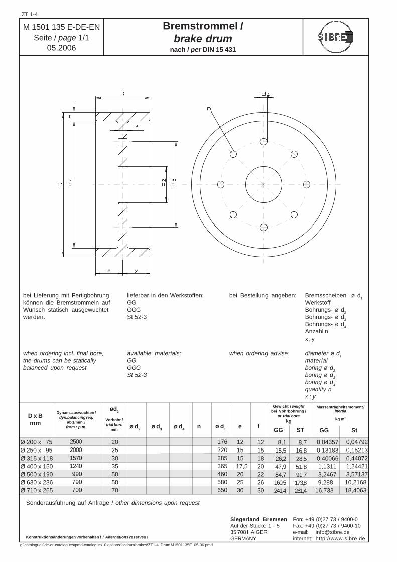
Ø 200 x 75 Ø 250 x 95 Ø 315 x 118 Ø 400 x 150 Ø 500 x 190 Ø 630 x 236 Ø 710 x 265
2500200015701240 990 790 700
20 25 30 35 50 50 70
176 220 285 365 460 580 650
12 15 15 17,5 20 25 30
12 15 18 20 22 26 30
8,1 15,5 26,2 47,9 84,7160,5241,4
8,7 16,8 28,5 51,8 91,7173,8261,4
0,04357 0,13183 0,40066 1,1311 3,2467 9,288 16,733
0,04792 0,15213 0,44072 1,24421 3,57137 10,2168 18,4063
D x Bmm
GG StGG ST
Dynam. auswuchten /dyn.balancing req.
ab 1/min. /from r.p.m. feø d
1
Gewicht / weightbei Vohrbohrung /
at trial borekg
Massenträgheitsmoment /inertia
kg m2
ød2
Vorbohr./trial bore
mmø d
2ø d
3ø d
4n
bei Lieferung mit Fertigbohrungkönnen die Bremstrommeln aufWunsch statisch ausgewuchtetwerden.
when ordering incl. final bore,the drums can be staticallybalanced upon request
lieferbar in den Werkstoffen:GGGGGSt 52-3
available materials:GGGGGSt 52-3
bei Bestellung angeben: Bremsscheiben ø d1
WerkstoffBohrungs- ø d
2
Bohrungs- ø d3
Bohrungs- ø d4
Anzahl nx ; y
when ordering advise: diameter ø d1
materialboring ø d
2
boring ø d3
boring ø d4
quantity nx ; y
Bremstrommel /brake drum
nach / per DIN 15 431
M 1501 135 E-DE-ENSeite / page 1/1
05.2006
Konstruktionsänderungen vorbehalten ! / Alternations reserved !
Sonderausführung auf Anfrage / other dimensions upon request
ZT 1-4
Siegerland Bremsen Fon: +49 (0)27 73 / 9400-0Auf der Stücke 1 - 5 Fax: +49 (0)27 73 / 9400-1035 708 HAIGER e-mail: [email protected] internet: http://www.sibre.de
g:\catalogues\de-en catalogues\pmd-catalogue\10 options for drum brakes\ZT1-4 Drum M1501135E 05-06.pmd
1/min.[V]
(30m/s)
Kupplungs-typen
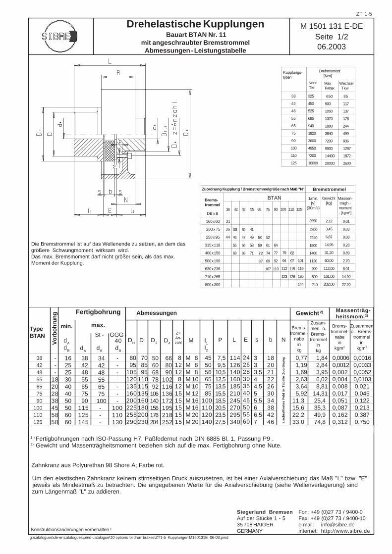
Drehelastische Kupplungen Bauart BTAN Nr. 11
mit angeschraubter BremstrommelAbmessungen - Leistungstabelle
TypeBTAN
Gewicht 2)
L E s b N
Zusam-men o.Brems-trommel
inkg
Zusammeno. Brems-trommel
inkgm2
Brems-trommel-
nabein
kgm2
Brems-trommel-
nabeinkg
Vo
rbo
hru
ng
DH
D D2 D
4I1
I2
MZ=An-zahl P
Abmessungen
1 ) Fertigbohrungen nach ISO-Passung H7, Paßfedernut nach DIN 6885 Bl. 1, Passung P9 . 2) Gewicht und Massenträgheitsmoment beziehen sich auf die max. Fertigbohrung ohne Nute.
Zahnkranz aus Polyurethan 98 Shore A; Farbe rot.
Um den elastischen Zahnkranz keinem stirnseitigen Druck auszusetzen, ist bei einer Axialverschiebung das Maß "L" bzw. "E" jeweils als Mindestmaß zu betrachten. Die angegebenen Werte für die Axialverschiebung (siehe Wellenverlagerung) sind zum Längenmaß "L" zu addieren.
Massenträg-heitsmom.2)
2,12
3,45
6,87
14,95
31,20
60,00
112,00
161,00
202,00
Massen-trägh.-moment. [kgm2]
0,01
0,03
0,08
0,28
0,89
2,70
8,01
14,90
27,20
BTAN Gewicht[kg]
2800
2240
1800
3550
1400
1120
900
800
710
BremstrommelZuordnung Kupplung / Bremstrommelgröße nach Maß "N"
DB x B
160 x 60
200 x 75
250 x 95
315 x 118
400 x 150
500 x 190
630 x 236
710 x 265
800 x 300
Brems-trommel
38
42
48
55
65
75
90
100
110
125
325
450
525
685
940
1920
3600
4950
7200
10000
650
900
1050
1370
1880
3840
7200
9900
14400
20000
85
117
137
178
244
499
936
1287
1872
2600
Die Bremstrommel ist auf das Wellenende zu setzen, an dem dasgrößere Schwungmoment wirksam wird.Das max. Bremsmoment darf nicht größer sein, als das max.Moment der Kupplung.
dA
max.min.
dA
dB
St -
dB
GGG -40d
B
- - -18202838455858
16 25 25 30 40 40 50 50 60 60
38 42 48 55 65 75 90115125145
34 42 48 55 65 75 100 - - -
- - - - - - -100110130
80 95105120135160200225255290
70 85 95110115135160180200230
50 60 68 78 92106140156176204
66 80 90102116136172195218252
81212 8121515151515
M 8M 8M 8M 10M 10M 12M 16M 16M 20M 20
45 50 56 65 75 85100110120140
7,5 9,510,512,513,515,518,520,523,527,5
114126140160185210245270295340
24262830354045505560
3 3 3,5 4 4,5 5 5,5 6 6,5 7
18202122263034384246
0,77 1,19 1,69 2,63 3,64 5,9211,315,622,233,0
1,84 2,84 3,95 6,02 8,81 14,31 25,4 35,3 49,9 74,8
0,00060,00120,0020,0040,0080,0170,0510,0870,1620,312
0,0016 0,0033 0,0052 0,0103 0,021 0,045 0,122 0,213 0,387 0,750
38 42 48 55 65 75 90100110125
Nenn Tkn
MaxTkmax
Wechsel Tkw
Drehmoment [Nm]
38 42 48 55 65 75 90 100 110 125
31
36
44
64
77
92
110
79
94
112
123
39
47
56
69
38
46
55
68
41
49
58
71
52
61
74
89
107
50
59
72
87
82
97
115
126s.
sch
raff
iert
es F
eld
in
Tab
elle
Zu
ord
nu
ng
Fertigbohrung
Konstruktionsänderungen vorbehalten !
M 1501 131 E-DESeite 1/206.2003
101
119
130
144
ZT 1-5
Siegerland Bremsen Fon: +49 (0)27 73 / 9400-0Auf der Stücke 1 - 5 Fax: +49 (0)27 73 / 9400-1035 708 HAIGER e-mail: [email protected] internet: http://www.sibre.de
g:\catalogues\de-en catalogues\pmd-catalogue\10 options for drum brakes\ZT1-5 Kupplungen M150131E 06-03.pmd
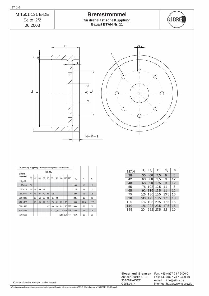
BTAN
Zuordnung Kupplung / Bremstrommelgröße nach Maß "N"
Brems-trommel
d1
140
176
220
285
365
460
580
650
DB x B
160 x 60
200 x 75
250 x 95
315 x 118
400 x 150
500 x 190
630 x 236
710 x 265
e f
10
12
15
15
17,5
20
25
30
10
12
15
15
17,5
20
25
30
50 60 68 78 92106140156176204
7,5 9,510,512,513,515,518,520,523,527,5
BTAN 38 42 48 55 65 75 90100110125
66 80 90102116136172195222252
9 9 9111113,517,517,517,522
81212 8121010151510
38 42 48 55 65 75 90 100 110 125
31
36
44
41
49
58
71 82
97
115
126
101
119
130
38
46
55
68
50
59
72
87
64
77
92
110
52
61
74
89
107
39
47
56
69 79
94
112
123
D2
D4
P d4 n
M 1501 131 E-DESeite 2/206.2003
Bremstrommelfür drehelastische Kupplung
Bauart BTAN Nr. 11
Konstruktionsänderungen vorbehalten !
ZT 1-6
Siegerland Bremsen Fon: +49 (0)27 73 / 9400-0Auf der Stücke 1 - 5 Fax: +49 (0)27 73 / 9400-1035 708 HAIGER e-mail: [email protected] internet: http://www.sibre.de
g:\catalogues\de-en catalogues\pmd-catalogue\10 options for drum brakes\ZT1-5 Kupplungen M150131E 06-03.pmd
1/min.[V]
(30m/s)
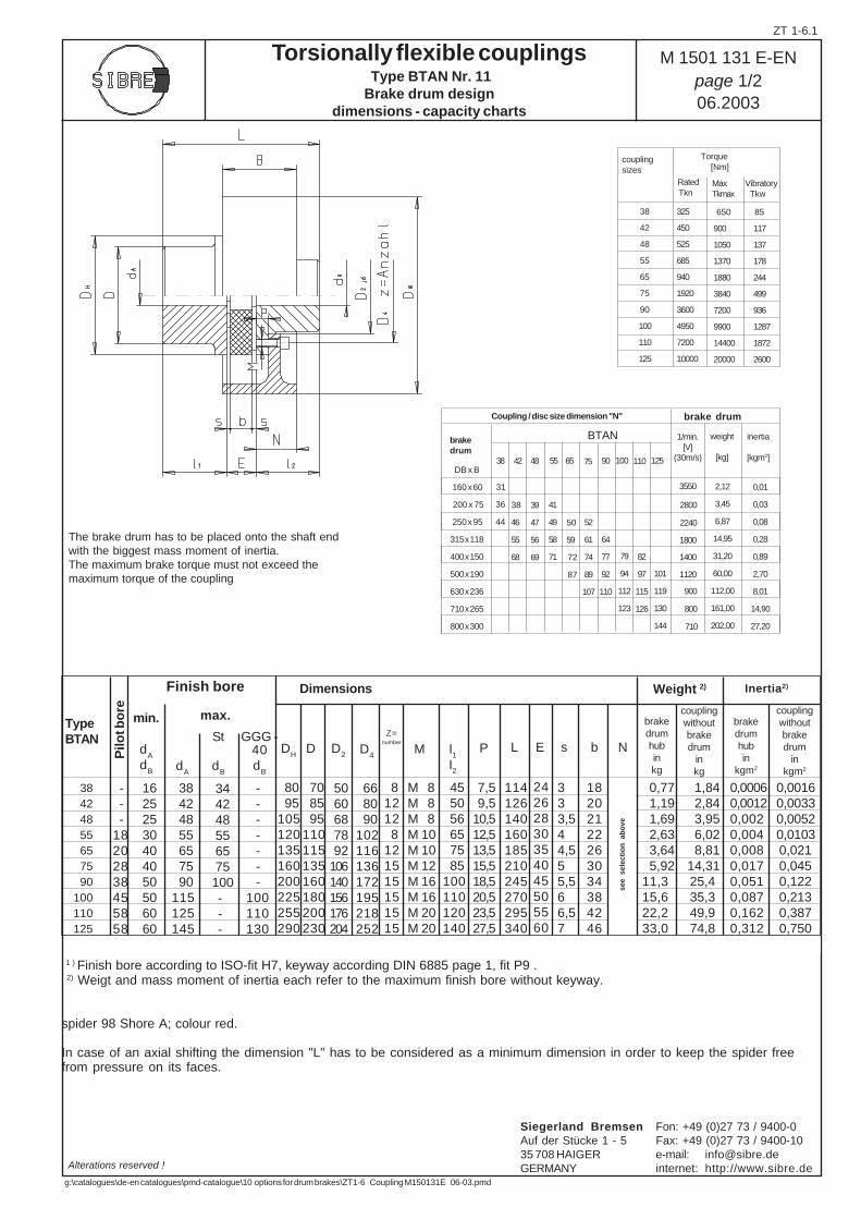
couplingsizes
Torsionally flexible couplings Type BTAN Nr. 11Brake drum design
dimensions - capacity charts
TypeBTAN
Weight 2)
L E s b N
couplingwithoutbrakedrum
inkg
couplingwithoutbrakedrum
inkgm2
brakedrumhubin
kgm2
brakedrumhubinkg
Pilo
t bo
re
DH
D D2 D
4I1
I2
MZ=
number
P
Dimensions
1 ) Finish bore according to ISO-fit H7, keyway according DIN 6885 page 1, fit P9 . 2) Weigt and mass moment of inertia each refer to the maximum finish bore without keyway.
spider 98 Shore A; colour red.
In case of an axial shifting the dimension "L" has to be considered as a minimum dimension in order to keep the spider freefrom pressure on its faces.
Inertia2)
2,12
3,45
6,87
14,95
31,20
60,00
112,00
161,00
202,00
inertia
[kgm2]
0,01
0,03
0,08
0,28
0,89
2,70
8,01
14,90
27,20
BTAN weight
[kg]
2800
2240
1800
3550
1400
1120
900
800
710
brake drumCoupling / disc size dimension "N"
DB x B
160 x 60
200 x 75
250 x 95
315 x 118
400 x 150
500 x 190
630 x 236
710 x 265
800 x 300
brakedrum
38
42
48
55
65
75
90
100
110
125
325
450
525
685
940
1920
3600
4950
7200
10000
650
900
1050
1370
1880
3840
7200
9900
14400
20000
85
117
137
178
244
499
936
1287
1872
2600
The brake drum has to be placed onto the shaft endwith the biggest mass moment of inertia.The maximum brake torque must not exceed themaximum torque of the coupling
dA
max.min.
dA
dB
St
dB
GGG -40d
B
- - -18202838455858
16 25 25 30 40 40 50 50 60 60
38 42 48 55 65 75 90115125145
34 42 48 55 65 75 100 - - -
- - - - - - -100110130
80 95105120135160200225255290
70 85 95110115135160180200230
50 60 68 78 92106140156176204
66 80 90102116136172195218252
81212 8121515151515
M 8M 8M 8M 10M 10M 12M 16M 16M 20M 20
45 50 56 65 75 85100110120140
7,5 9,510,512,513,515,518,520,523,527,5
114126140160185210245270295340
24262830354045505560
3 3 3,5 4 4,5 5 5,5 6 6,5 7
18202122263034384246
0,77 1,19 1,69 2,63 3,64 5,9211,315,622,233,0
1,84 2,84 3,95 6,02 8,81 14,31 25,4 35,3 49,9 74,8
0,00060,00120,0020,0040,0080,0170,0510,0870,1620,312
0,0016 0,0033 0,0052 0,0103 0,021 0,045 0,122 0,213 0,387 0,750
38 42 48 55 65 75 90100110125
Rated Tkn
MaxTkmax
Vibratory Tkw
Torque [Nm]
38 42 48 55 65 75 90 100 110 125
31
36
44
64
77
92
110
79
94
112
123
39
47
56
69
38
46
55
68
41
49
58
71
52
61
74
89
107
50
59
72
87
82
97
115
126se
e se
lect
ion
ab
ove
Finish bore
Alterations reserved !
M 1501 131 E-ENpage 1/206.2003
101
119
130
144
ZT 1-6.1
Siegerland Bremsen Fon: +49 (0)27 73 / 9400-0Auf der Stücke 1 - 5 Fax: +49 (0)27 73 / 9400-1035 708 HAIGER e-mail: [email protected] internet: http://www.sibre.de
g:\catalogues\de-en catalogues\pmd-catalogue\10 options for drum brakes\ZT1-6 Coupling M150131E 06-03.pmd
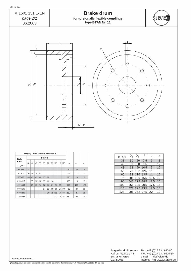
BTAN
coupling / brake drum size dimension "N"
Brakedrum
d1
140
176
220
285
365
460
580
650
DB x B
160 x 60
200 x 75
250 x 95
315 x 118
400 x 150
500 x 190
630 x 236
710 x 265
e f
10
12
15
15
17,5
20
25
30
10
12
15
15
17,5
20
25
30
50 60 68 78 92106140156176204
7,5 9,510,512,513,515,518,520,523,527,5
BTAN 38 42 48 55 65 75 90100110125
66 80 90102116136172195222252
9 9 9111113,517,517,517,522
81212 8121010151510
38 42 48 55 65 75 90 100 110 125
31
36
44
41
49
58
71 82
97
115
126
101
119
130
38
46
55
68
50
59
72
87
64
77
92
110
52
61
74
89
107
39
47
56
69 79
94
112
123
D2
D4
P d4 n
M 1501 131 E-ENpage 2/206.2003
Brake drumfor torsionally flexible couplings
type BTAN Nr. 11
Alterations reserved !
ZT 1-6.2
Siegerland Bremsen Fon: +49 (0)27 73 / 9400-0Auf der Stücke 1 - 5 Fax: +49 (0)27 73 / 9400-1035 708 HAIGER e-mail: [email protected] internet: http://www.sibre.de
g:\catalogues\de-en catalogues\pmd-catalogue\10 options for drum brakes\ZT1-6 Coupling M150131E 06-03.pmd
Konstruktionsänderungen vorbehalten ! / Alterations reserved !
A 273 E-DE-ENSeite / page 1/1
08.2001
TKN
TKmax
in Nm in Nm
0032S 500 15000063S 900 2800016S 2100 6400025S 3600 11000063S 8300 25000
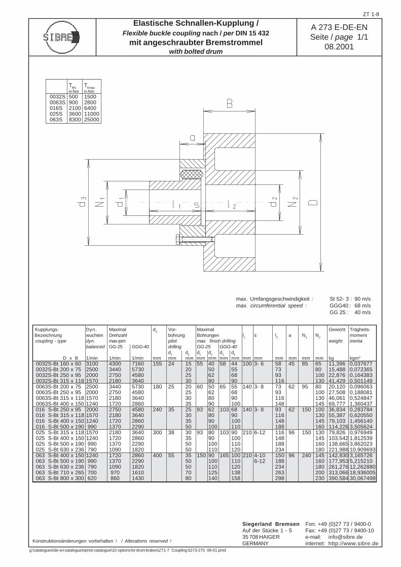
Elastische Schnallen-Kupplung /Flexible buckle coupling nach / per DIN 15 432
mit angeschraubter Bremstrommelwith bolted drum
0032S-Bt 160 x 60 3100 4300 7160 155 24 15 55 40 58 44 100 3- 6 58 45 85 65 11,396 0,037677 0032S-Bt 200 x 75 2500 3440 5730 20 50 55 73 80 15,488 0,072365 0032S-Bt 250 x 95 2000 2750 4580 25 62 68 93 100 22,876 0,164383 0032S-Bt 315 x 118 1570 2180 3640 30 80 90 116 130 41,429 0,501149 0063S-Bt 200 x 75 2500 3440 5730 180 25 20 60 50 65 55 140 3- 8 73 62 95 80 20,120 0,096063 0063S-Bt 250 x 95 2000 2750 4580 25 62 68 93 100 27,508 0,188081 0063S-Bt 315 x 118 1570 2180 3640 30 80 90 116 130 46,061 0,524847 0063S-Bt 400 x 150 1240 1720 2860 35 90 100 148 145 69,777 1,360437 016 S-Bt 250 x 95 2000 2750 4580 240 35 25 93 62 103 68 140 3- 8 93 62 150 100 36,834 0,283784 016 S-Bt 315 x 118 1570 2180 3640 30 80 90 116 130 55,387 0,620550 016 S-Bt 400 x 150 1240 1720 2860 35 90 100 148 145 79,103 1,456140 016 S-Bt 500 x 190 990 1370 2290 50 100 110 188 160 114,226 3,505624 025 S-Bt 315 x 118 1570 2180 3640 300 38 30 93 80 103 90 210 6-12 116 96 150 130 79,826 0,976949 025 S-Bt 400 x 150 1240 1720 2860 35 90 100 148 145 103,542 1,812539 025 S-Bt 500 x 190 990 1370 2290 50 100 110 188 160 138,665 3,862023 025 S-Bt 630 x 236 790 1090 1820 50 110 120 234 180 221,988 10,909693 063 S-Bt 400 x 150 1240 1720 2860 400 55 35 150 90 165 100 210 4-10 150 96 240 145 142,830 3,165726 063 S-Bt 500 x 190 990 1370 2290 50 100 110 6-12 188 160 177,953 5,215210 063 S-Bt 630 x 236 790 1090 1820 50 110 120 234 180 261,276 12,262880 063 S-Bt 710 x 265 700 970 1610 70 125 138 263 200 313,066 18,936005 063 S-Bt 800 x 300 620 860 1430 80 140 158 298 230 390,584 30,067498
Kupplungs- Dyn. Maximal d3
Vor- Maximal Gewicht Trägheits- Bezeichnung wuchten Drehzahl bohrung Bohrungen l
1s l
2a N
1N
2moment
coupling - type dyn. max.rpm pilot max. finish drilling weight inertiabalanced GG-25 GGG-40 drilling GG-25 GGG-40
d1
d2
d1
d2
d1
d2
D x B 1/min 1/min 1/min mm mm mm mm mm mm mm mm mm mm mm mm mm kg kgm2
max. Umfangsgeschwindigkeit : St 52- 3 : 90 m/smax. circumferential speed : GGG40 : 68 m/s
GG 25 : 40 m/s
ZT 1-8
Siegerland Bremsen Fon: +49 (0)27 73 / 9400-0Auf der Stücke 1 - 5 Fax: +49 (0)27 73 / 9400-1035 708 HAIGER e-mail: [email protected] internet: http://www.sibre.de
g:\catalogues\de-en catalogues\pmd-catalogue\10 options for drum brakes\ZT1-7 Coupling S273-275 08-01.pmd
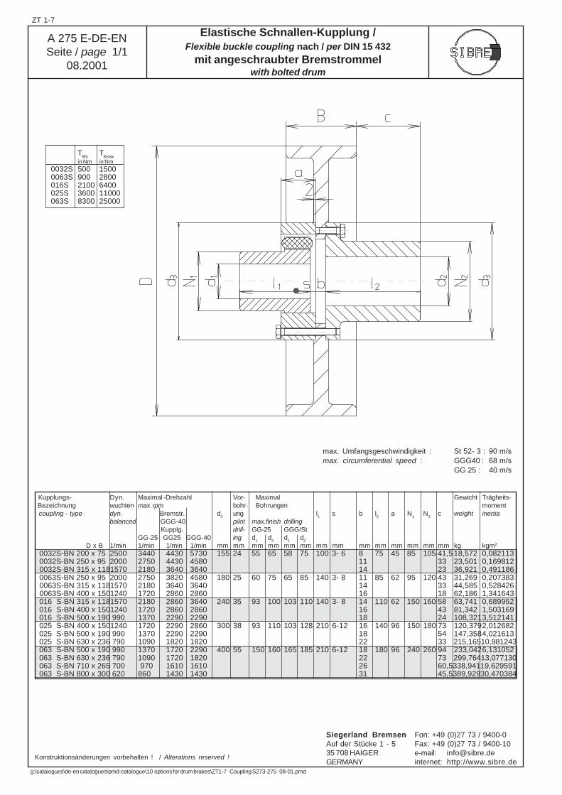
Kupplungs- Dyn. Maximal -Drehzahl Vor- Maximal Gewicht Trägheits- Bezeichnung wuchten max. rpm bohr- Bohrungen moment coupling - type dyn. Bremstr. d
3ung l
1s b l
2a N
1N
2c weight inertia
balanced GGG-40 pilot max.finish drilling Kupplg. drill- GG-25 GGG/StGG-25 GG25 GGG-40 ing d
1d
2d
1d
2
D x B 1/min 1/min 1/min 1/min mm mm mm mm mm mm mm mm mm mm mm mm mm mm kg kgm2
0032S-BN 200 x 75 2500 3440 4430 5730 155 24 55 65 58 75 100 3- 6 8 75 45 85 105 41,5 18,572 0,082113 0032S-BN 250 x 95 2000 2750 4430 4580 11 33 23,501 0,169812 0032S-BN 315 x 1181570 2180 3640 3640 14 23 36,921 0,491186 0063S-BN 250 x 95 2000 2750 3820 4580 180 25 60 75 65 85 140 3- 8 11 85 62 95 120 43 31,269 0,207383 0063S-BN 315 x 1181570 2180 3640 3640 14 33 44,585 0,528426 0063S-BN 400 x 1501240 1720 2860 2860 16 18 62,186 1,341643 016 S-BN 315 x 1181570 2180 2860 3640 240 35 93 100 103 110 140 3- 8 14 110 62 150 160 58 63,741 0,689952 016 S-BN 400 x 1501240 1720 2860 2860 16 43 81,342 1,503169 016 S-BN 500 x 190 990 1370 2290 2290 18 24 108,3213,512141 025 S-BN 400 x 1501240 1720 2290 2860 300 38 93 110 103 128 210 6-12 16 140 96 150 180 73 120,3792,012682 025 S-BN 500 x 190 990 1370 2290 2290 18 54 147,3584,021613 025 S-BN 630 x 236 790 1090 1820 1820 22 33 215,16510,981243 063 S-BN 500 x 190 990 1370 1720 2290 400 55 150 160 165 185 210 6-12 18 180 96 240 260 94 233,0426,131052 063 S-BN 630 x 236 790 1090 1720 1820 22 73 299,76413,077130 063 S-BN 710 x 265 700 970 1610 1610 26 60,5338,94119,629591 063 S-BN 800 x 300 620 860 1430 1430 31 45,5389,92930,470384
Konstruktionsänderungen vorbehalten ! / Alterations reserved !
A 275 E-DE-ENSeite / page 1/1
08.2001
Elastische Schnallen-Kupplung /Flexible buckle coupling nach / per DIN 15 432
mit angeschraubter Bremstrommelwith bolted drum
TKN
TKmax
in Nm in Nm
0032S 500 15000063S 900 2800016S 2100 6400025S 3600 11000063S 8300 25000
max. Umfangsgeschwindigkeit : St 52- 3 : 90 m/smax. circumferential speed : GGG40 : 68 m/s
GG 25 : 40 m/s
ZT 1-7
Siegerland Bremsen Fon: +49 (0)27 73 / 9400-0Auf der Stücke 1 - 5 Fax: +49 (0)27 73 / 9400-1035 708 HAIGER e-mail: [email protected] internet: http://www.sibre.de
g:\catalogues\de-en catalogues\pmd-catalogue\10 options for drum brakes\ZT1-7 Coupling S273-275 08-01.pmd
ZT1-8.1
Alterations reserved Siegerland Bremsen – Emde GmbH & Co. KG – Auf der Stücke 1-5 – D-35708 Haiger, Germany
Tel.: +49 2773 94000 – Fax: +49 2773 9400-10 – e-mail: [email protected] – www.sibre.de
G:\CATALOGUES\DE-EN CATALOGUES\DOC-CATALOGUE\10 Options for Drum Brakes\ZT1-81 Couplings APC-A 2008-02.doc
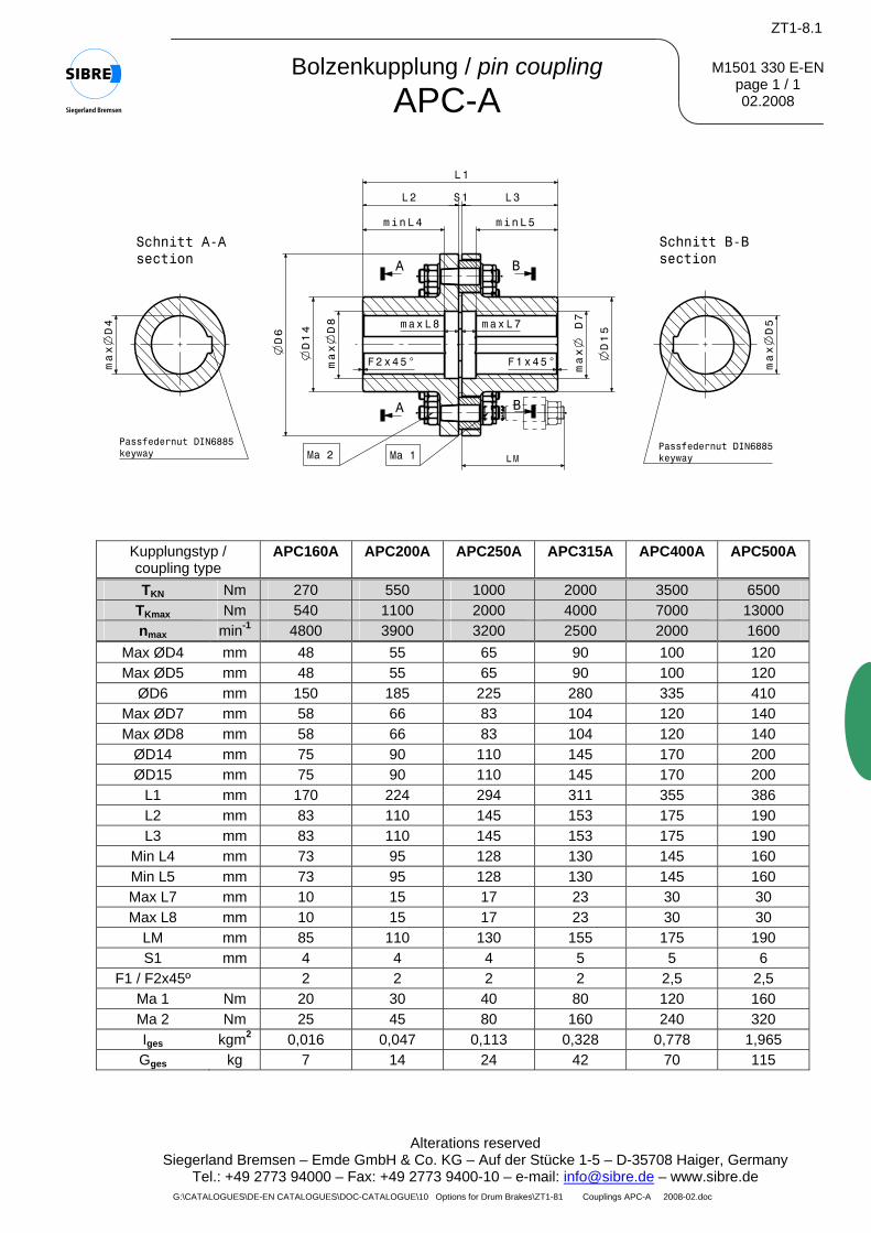
M1501 330 E-ENpage 1 / 1 02.2008
Kupplungstyp / coupling type
APC160A APC200A APC250A APC315A APC400A APC500A
TKN Nm 270 550 1000 2000 3500 6500 TKmax Nm 540 1100 2000 4000 7000 13000 nmax min-1 4800 3900 3200 2500 2000 1600
Max ØD4 mm 48 55 65 90 100 120 Max ØD5 mm 48 55 65 90 100 120
ØD6 mm 150 185 225 280 335 410 Max ØD7 mm 58 66 83 104 120 140 Max ØD8 mm 58 66 83 104 120 140
ØD14 mm 75 90 110 145 170 200 ØD15 mm 75 90 110 145 170 200
L1 mm 170 224 294 311 355 386 L2 mm 83 110 145 153 175 190 L3 mm 83 110 145 153 175 190
Min L4 mm 73 95 128 130 145 160 Min L5 mm 73 95 128 130 145 160 Max L7 mm 10 15 17 23 30 30 Max L8 mm 10 15 17 23 30 30
LM mm 85 110 130 155 175 190 S1 mm 4 4 4 5 5 6
F1 / F2x45º 2 2 2 2 2,5 2,5 Ma 1 Nm 20 30 40 80 120 160 Ma 2 Nm 25 45 80 160 240 320 Iges kgm2 0,016 0,047 0,113 0,328 0,778 1,965 Gges kg 7 14 24 42 70 115
Bolzenkupplung / pin coupling APC-A
ZT1-8.2
Alterations reserved Siegerland Bremsen – Emde GmbH & Co. KG – Auf der Stücke 1-5 – D-35708 Haiger, Germany
Tel.: +49 2773 94000 – Fax: +49 2773 9400-10 – e-mail: [email protected] – www.sibre.de G:\CATALOGUES\DE-EN CATALOGUES\DOC-CATALOGUE\10 Options for Drum Brakes\ZT1-82 Couplings APC-AT 2008-08.doc
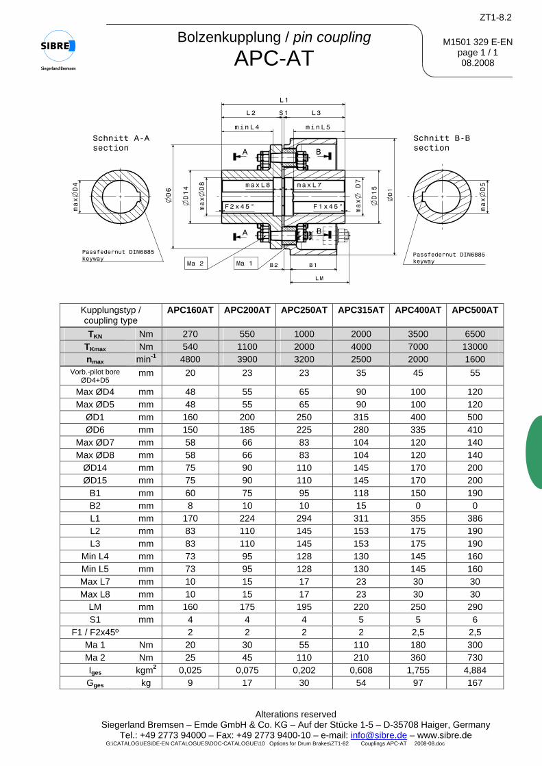
M1501 329 E-ENpage 1 / 1 08.2008
Bolzenkupplung / pin coupling APC-AT
Kupplungstyp / coupling type
APC160AT APC200AT APC250AT APC315AT APC400AT APC500AT
TKN Nm 270 550 1000 2000 3500 6500 TKmax Nm 540 1100 2000 4000 7000 13000 nmax min-1 4800 3900 3200 2500 2000 1600
Vorb.-pilot bore ØD4+D5
mm 20 23 23 35 45 55
Max ØD4 mm 48 55 65 90 100 120 Max ØD5 mm 48 55 65 90 100 120
ØD1 mm 160 200 250 315 400 500 ØD6 mm 150 185 225 280 335 410
Max ØD7 mm 58 66 83 104 120 140 Max ØD8 mm 58 66 83 104 120 140
ØD14 mm 75 90 110 145 170 200 ØD15 mm 75 90 110 145 170 200
B1 mm 60 75 95 118 150 190 B2 mm 8 10 10 15 0 0 L1 mm 170 224 294 311 355 386 L2 mm 83 110 145 153 175 190 L3 mm 83 110 145 153 175 190
Min L4 mm 73 95 128 130 145 160 Min L5 mm 73 95 128 130 145 160 Max L7 mm 10 15 17 23 30 30 Max L8 mm 10 15 17 23 30 30
LM mm 160 175 195 220 250 290 S1 mm 4 4 4 5 5 6
F1 / F2x45º 2 2 2 2 2,5 2,5 Ma 1 Nm 20 30 55 110 180 300 Ma 2 Nm 25 45 110 210 360 730 Iges kgm2 0,025 0,075 0,202 0,608 1,755 4,884 Gges kg 9 17 30 54 97 167
Konstruktionsänderungen vorbehalten.
G:\CATALOGUES\DE-EN CATALOGUES\DOC-CATALOGUE\10 Options for Drum Brakes\DE ZT1-8.3 Kupplung ALC-AT 2008_09.doc
ZT1-8.3
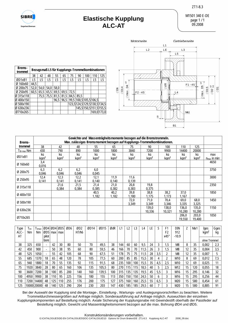
M1501 340 E-DE page 1 / 1 09.2008
Elastische Kupplung ALC-AT
MotorseiteL1
B1
H7
ma
x.
D5
D1
5 H7
h6
D2 D
1
D6
D1
4H
7 m
ax
.D
4 dR
L2 LE L3
S
L4
45F1
45F2
L5
Ma1
Getriebeseite
Gewichte und Massenträgheitsmomente bezogen auf die Bremstrommeln. Max. zulässiges Bremsmoment bezogen auf Kupplungs-Trommelkombinationen. Brems-
trommel 38 42 48 55 65 75 90 100 110 125 TBr max Nm 430 790 890 1000 1800 3840 7200 9900 14400 20000
kg kg kg kg kg kg kg kg kg kg max ØD1xB1 kgm² kgm² kgm² kgm² kgm² kgm² kgm² kgm² kgm² kgm² nmax in min-
3,4 4650Ø 160x60 0,016 6,3 6,2 6,2 6,0 3750Ø 200x75 0,046 0,046 0,046 0,045 12,4 12,3 12,2 12,1 11,9 11,6 3000Ø 250x95 0,141 0,141 0,141 0,140 0,140 0,139
21,6 21,5 21,4 21,0 20,8 19,8 2350Ø 315x118 0,384 0,384 0,385 0,382 0,383 0,375 40,5 40,2 39,8 38,8 38,2 37,0 1850Ø 400x150 1,182 1,182 1,180 1,175 1,173 1,167 72,0 71,0 70,4 69,0 68,0 1450Ø 500x190 3,349 3,349 3,346 3,335 3,325 139,0 138,0 136,0 135,0 1150Ø 630x236 10,336 10,321 10,280 10,280 206,0 203,0 1050Ø710x265 19,550 19,400
Brems- trommel Bezugsmaß L5 für Kupplungs-Trommelkombinationen
38 42 48 55 65 75 90 100 110 125ØD1xB1 L5 L5 L5 L5 L5 L5 L5 L5 L5 L5 Ø 160x60 44,5 Ø 200x75 52,0 54,0 54,0 58,0 Ø 250x95 60,5 65,5 65,5 69,5 69,5 72,5 Ø 315x118 75,5 75,5 81,5 81,5 84,5 85,5 Ø 400x150 96,5 96,5 99,5 100,5 105,5 106,5 Ø 500x190 123,5 124,5 129,5 130,5 134,5Ø 630x236 145,5 150,5 151,5 155,5Ø710x265 169,0 173,0
Iges kgm²
Ggeskg
Type ALC- AT
Tkn Nm
Tkmax Nm
ØD4 ØD5 pilot bore
ØD4 max
ØD5 max
ØD6 ØD2 H7/h6
ØD14 ØD15 ØdR L1 L2 L3 L4 LE S F1 F2
x45°
DIN 912
-10.9
Z Ma1
ohne Trommel 38 325 650 - 42 30 80 50 70 49,5 38 144 60 60 9,5 24 3 1,5 M8 8 35 0,002 2,3 42 450 900 - 50 38 95 60 80 59,5 46 166 70 70 11,5 26 3 1,5 M8 12 35 0,004 3,5 48 525 1050 - 55 42 105 68 90 67,5 51 178 75 75 11,5 28 3,5 2 M8 12 35 0,007 5 55 685 1370 18 65 48 120 78 105 77,5 60 200 85 85 15,5 30 4 2 M10 8 69 0,012 7,5 65 940 1880 18 70 55 135 92 115 91,5 68 235 100 100 15,5 35 4,5 2,5 M10 12 69 0,025 11 75 1920 3840 28 80 65 160 106 135 105,5 80 270 115 115 18,5 40 5 2,5 M12 15 120 0,055 18 90 3600 7200 38 100 85 200 140 160 139,5 100 315 135 135 19,5 45 5,5 3 M16 15 295 0,146 32 100 4950 9900 38 110 95 225 156 180 155 113 350 150 150 24,5 50 6 3 M16 15 295 0,256 44 110 7200 14400 48 125 110 255 176 200 175 127 375 160 160 25,5 55 6,5 3 M20 15 580 0,454 61 125 10000 20000 48 140 125 290 204 230 203 147 430 185 185 29,5 60 7 3 M20 15 580 0,885 91
Bei der Auswahl der Kupplung sind die Montage-, Einstellung-, Wartungs- und Auslegungsvorschriften zu beachten. Weitere Trommeldurchmessergrößen auf Anfrage möglich. Sonderausführung auf Anfrage möglich. Auswuchten der einzelnen
Kupplungskomponenten auf Bestellung möglich. Axiale Sicherung der Kupplungsnabe mit Gewindestift oberhalb der Passfeder auf Bestellung möglich. Gewicht und Massenträgheitsmoment bezogen auf die max. Bohrung ØD4 und ØD5.
Konstruktionsänderungen vorbehalten.
G:\CATALOGUES\DE-EN CATALOGUES\DOC-CATALOGUE\10 Options for Drum Brakes\DE ZT1-8.5 Kupplung ALC-A 2008-02.doc
ZT1-8.5
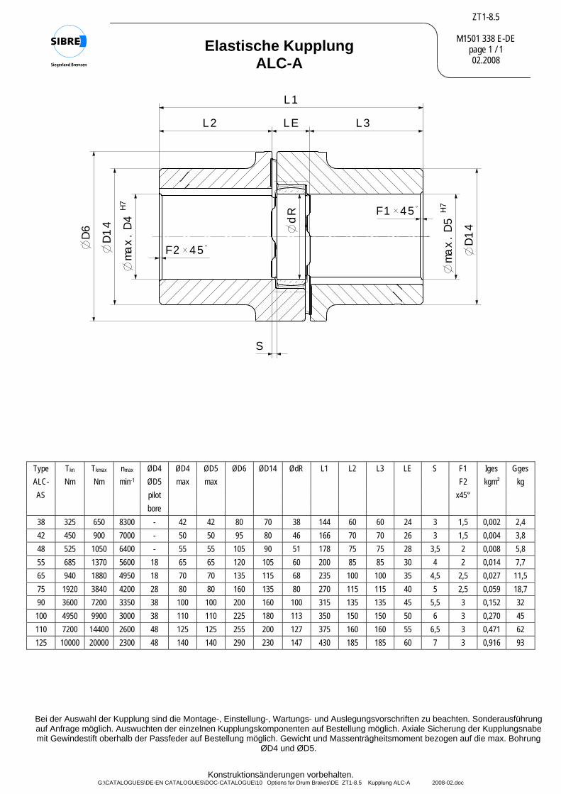
M1501 338 E-DE page 1 / 1 02.2008
Elastische Kupplung ALC-A
Bei der Auswahl der Kupplung sind die Montage-, Einstellung-, Wartungs- und Auslegungsvorschriften zu beachten. Sonderausführung auf Anfrage möglich. Auswuchten der einzelnen Kupplungskomponenten auf Bestellung möglich. Axiale Sicherung der Kupplungsnabe mit Gewindestift oberhalb der Passfeder auf Bestellung möglich. Gewicht und Massenträgheitsmoment bezogen auf die max. Bohrung
ØD4 und ØD5.
L1
45F2
D6
D1
4H7
ma
x.
D4
45F1
dR
L2 LE L3
S
D1
4
H7
ma
x.
D5
Type Tkn Tkmax nmax ØD4 ØD4 ØD5 ØD6 ØD14 ØdR L1 L2 L3 LE S F1 Iges Gges ALC- Nm Nm min-1 ØD5 max max F2 kgm² kg AS pilot x45° bore
38 325 650 8300 - 42 42 80 70 38 144 60 60 24 3 1,5 0,002 2,4 42 450 900 7000 - 50 50 95 80 46 166 70 70 26 3 1,5 0,004 3,8 48 525 1050 6400 - 55 55 105 90 51 178 75 75 28 3,5 2 0,008 5,8 55 685 1370 5600 18 65 65 120 105 60 200 85 85 30 4 2 0,014 7,7 65 940 1880 4950 18 70 70 135 115 68 235 100 100 35 4,5 2,5 0,027 11,5 75 1920 3840 4200 28 80 80 160 135 80 270 115 115 40 5 2,5 0,059 18,7 90 3600 7200 3350 38 100 100 200 160 100 315 135 135 45 5,5 3 0,152 32 100 4950 9900 3000 38 110 110 225 180 113 350 150 150 50 6 3 0,270 45 110 7200 14400 2600 48 125 125 255 200 127 375 160 160 55 6,5 3 0,471 62 125 10000 20000 2300 48 140 140 290 230 147 430 185 185 60 7 3 0,916 93

���
������������������ ��������������
�������
� ������������������������ ��� ����������������������������������������������� ����������� ������������������� ������� !!��������������������"������������� ������������������ ������������������� ���������������������������#���������$������������������������� ������� ������������ � �%��������&����������'������� ������������ ����� ���������
(�)�)"���*+,* ��$-����.)���/������������� �!���������������"��������#$ �$������0���%�1�������&������&�����(��������"������������,�����������������/�
� ���%��� ��� �������������� ���������������� �� ����������� ������ ��#���
������������������ ���������������� ��������������� �� ��������������������� ���� ����������� ���� �����
�����������������������������������������������������
������������������������
����������������� �� �
�������������� �����
�������� ��
��������� ����
����������� ����
��������
��������������
������������������ �
�������������� �����
� ��������� ������ �
���������������������
������������ � ����� ������������������ ������
������
��������� ���� �� �� ���� ������������������������������������ � ! ���� ����������������������"�#�$%&' ��( )* )��+,)-��.��%&'/�01 )����� 2��3��444.,)-��.��
������������� �������������� ������������������������������������� ������������������� �� ���
������������������ �������������������������������������� ��
�
�
�
2/0���%����� ��� �
�����������%��������
' � 3 4 5 � � 6 7 8 *+�* ��.)
������
��������������
����������������
9
� ���� �� �������
#:
9�"������������������ �
���������������������������������������������������������������
�
5�*6������������

200250315400500630710
70 90110140180225255
8 8 10 10 12 12 15
20 25 30 35 40 45 50
35 40 50 62 80 100 112
65 80 100 125 160 200 224
32 37 44,5 50 58 63 70
2 2 3 3 3 3 3
132 162 204 256 320 400 452
15 15 18 18 20 20 22
140 170 212 260 320 390 440
20 20 20 20 20 20 20
- - - - - 144 170
- - 75 80100 82 95
35 30 33 15 15 20 20
- 45 55 - 90112,5 90
3 5 6 8 12 18 24
Ø d1 B c Ø d
2 e f g1
g2
h j k a1
a2 a
3 b
1 b
2
Nietbohrungen / drillings for riveting Anzahld. Niete /
no. ofrivets
Bremsbacken und Bremsbeläge fürTrommelbremsen nach DIN 15 435 Blatt 2
Brake shoe and brake liningfor drum brake per DIN 15 435 page 2
Ø 200 Ø 250
Ø 315 Ø 400
Ø 500 Ø 630
Ø 710
X
bei Belagbestellung angeben:Bremstrommel Ø D,Reibwert µ = 0,4when ordering please advice:drum diameter Ø D,friction coefficient µ = 0,4
X
bei Bremsbacken- Bremstrommel Ø Dbestellung angeben: Werkstoff: Leichtmetall, Grauguss,
Schweißkonstruktion mit oder ohne Nietbohrungenwhen order brake drum diameter Ø Dshoes please advise: material: aluminium, cast iron,
fabricated steel with or without drillings for riveting
Konstruktionsänderungen vorbehalten ! / Alterations reserved !
Sonderausführung auf Anfrage / other dimensions upon request
M 1501 93 E-DE-ENSeite / page 1/1
04.2000
g:\catalogues\de-en catalogues\pmd-catalogue\10 options for drum brakes\E1 Brake shoe M150193E 04-00.pmd
Siegerland Bremsen Fon: +49 (0)27 73 / 9400-0Auf der Stücke 1 - 5 Fax: +49 (0)27 73 / 9400-1035 708 HAIGER e-mail: [email protected] internet: http://www.sibre.de
E 1