zone 2-22 & zone 1-21 · 2018-01-04 · • set fault/idle output states •missing module...
TRANSCRIPT

Pneumaticvalve
islands
zone 2-22& zone 1-21
0144
0GB
-201
7/R
02A
vaila
bilit
y, d
esig
n an
d sp
ecifi
catio
ns a
re s
ubje
ct to
cha
nge
with
out n
otic
e. A
ll rig
hts
rese
rved
.
Fielbus Electronics - 155
Contents
0144
0GB
-201
7/R
02A
vaila
bilit
y, d
esig
n an
d sp
ecifi
catio
ns a
re s
ubje
ct to
cha
nge
with
out n
otic
e. A
ll rig
hts
rese
rved
.
ATEX Group II,Zone 2 and 22, Category 3 GD Islands series 501 . . . . . . . . . . . . . . . . . . . . . . . . . . . . . . . . . . . . . . . Features . . . . . . . . . . . . . . . . . . . . . . . . . . . . . . . . . . . . . . . . . . . . . . . . . . . . . . . . . . . . . . . . . . . . . . . . . 157-158 501 Specifications . . . . . . . . . . . . . . . . . . . . . . . . . . . . . . . . . . . . . . . . . . . . . . . . . . . . . . . . . . . . . . . . . . 159-160 How to Order - Assembly Kit . . . . . . . . . . . . . . . . . . . . . . . . . . . . . . . . . . . . . . . . . . . . . . . . . . . . . . . . . . . . 161 How to Order - Subbases / Valves. . . . . . . . . . . . . . . . . . . . . . . . . . . . . . . . . . . . . . . . . . . . . . . . . . . . . . 162-163 How to Order - Accessories. . . . . . . . . . . . . . . . . . . . . . . . . . . . . . . . . . . . . . . . . . . . . . . . . . . . . . . . . . . . . . 164 How to Order - G3 Electronics. . . . . . . . . . . . . . . . . . . . . . . . . . . . . . . . . . . . . . . . . . . . . . . . . . . . . . . . . . . . 165 How to Order - Connectors . . . . . . . . . . . . . . . . . . . . . . . . . . . . . . . . . . . . . . . . . . . . . . . . . . . . . . . . . . . . . . 166 ATEX certification . . . . . . . . . . . . . . . . . . . . . . . . . . . . . . . . . . . . . . . . . . . . . . . . . . . . . . . . . . . . . . . . . . . . . 183
Islands series 502 . . . . . . . . . . . . . . . . . . . . . . . . . . . . . . . . . . . . . . . Features . . . . . . . . . . . . . . . . . . . . . . . . . . . . . . . . . . . . . . . . . . . . . . . . . . . . . . . . . . . . . . . . . . . . . . . . 168..175 501 Specifications . . . . . . . . . . . . . . . . . . . . . . . . . . . . . . . . . . . . . . . . . . . . . . . . . . . . . . . . . . . . . . . . . . 175-172 How to Order - Assembly Kit . . . . . . . . . . . . . . . . . . . . . . . . . . . . . . . . . . . . . . . . . . . . . . . . . . . . . . . . . . . . 173 How to Order - Subbases / Valves. . . . . . . . . . . . . . . . . . . . . . . . . . . . . . . . . . . . . . . . . . . . . . . . . . . . . . . . . 174 How to Order - Accessories. . . . . . . . . . . . . . . . . . . . . . . . . . . . . . . . . . . . . . . . . . . . . . . . . . . . . . . . . . . . . . 175 How to Order - G3 Electronics. . . . . . . . . . . . . . . . . . . . . . . . . . . . . . . . . . . . . . . . . . . . . . . . . . . . . . . . . . . . 176 How to Order - Connectors . . . . . . . . . . . . . . . . . . . . . . . . . . . . . . . . . . . . . . . . . . . . . . . . . . . . . . . . . . . . . . 177 ATEX certification . . . . . . . . . . . . . . . . . . . . . . . . . . . . . . . . . . . . . . . . . . . . . . . . . . . . . . . . . . . . . . . . . . . . . 183
G3 Electronics . . . . . . . . . . . . . . . . . . . . . . . . . . . . . . . . . . . . . . . . . . Features . . . . . . . . . . . . . . . . . . . . . . . . . . . . . . . . . . . . . . . . . . . . . . . . . . . . . . . . . . . . . . . . . . . . . . . . . 179-180 G3 Platform Distribution Options. . . . . . . . . . . . . . . . . . . . . . . . . . . . . . . . . . . . . . . . . . . . . . . . . . . . . . . 181-182 ATEX certification . . . . . . . . . . . . . . . . . . . . . . . . . . . . . . . . . . . . . . . . . . . . . . . . . . . . . . . . . . . . . . . . . . . . . 183 DeviceNet™ . . . . . . . . . . . . . . . . . . . . . . . . . . . . . . . . . . . . . . . . . . . . . . . . . . . . . . . . . . . . . . . . . . . . . . . . . 184 EtherNet/IP™ . . . . . . . . . . . . . . . . . . . . . . . . . . . . . . . . . . . . . . . . . . . . . . . . . . . . . . . . . . . . . . . . . . . . . . . . 186 Modbus TCP . . . . . . . . . . . . . . . . . . . . . . . . . . . . . . . . . . . . . . . . . . . . . . . . . . . . . . . . . . . . . . . . . . . . . . . . . 188 Profibus-DP® . . . . . . . . . . . . . . . . . . . . . . . . . . . . . . . . . . . . . . . . . . . . . . . . . . . . . . . . . . . . . . . . . . . . . . . . . 190 PROFINET®. . . . . . . . . . . . . . . . . . . . . . . . . . . . . . . . . . . . . . . . . . . . . . . . . . . . . . . . . . . . . . . . . . . . . . . . . . 192 EtherNet/IP™ DLR . . . . . . . . . . . . . . . . . . . . . . . . . . . . . . . . . . . . . . . . . . . . . . . . . . . . . . . . . . . . . . . . . . . . 194 Inputs Modules - Digital Inputs - 5-Pin M12 Modules . . . . . . . . . . . . . . . . . . . . . . . . . . . . . . . . . . . . . . . . . . 196 Inputs Modules - Analog Inputs (16 Bit Resolution) . . . . . . . . . . . . . . . . . . . . . . . . . . . . . . . . . . . . . . . . . . . 196 Inputs Modules - Digital Inputs - Terminal Strip Modules . . . . . . . . . . . . . . . . . . . . . . . . . . . . . . . . . . . . . . . 196 Inputs Modules - Accessories . . . . . . . . . . . . . . . . . . . . . . . . . . . . . . . . . . . . . . . . . . . . . . . . . . . . . . . . . . . 197 G3 Backplane Extension Modules . . . . . . . . . . . . . . . . . . . . . . . . . . . . . . . . . . . . . . . . . . . . . . . . . . . . . . . . 199 G3 Backplane Extension Cables and Connectors . . . . . . . . . . . . . . . . . . . . . . . . . . . . . . . . . . . . . . . . . . . . 201 Dimensions - G3 Fieldbus Communication Assembly. . . . . . . . . . . . . . . . . . . . . . . . . . . . . . . . . . . . . . . 202-203 How to Order - G3 Electronics. . . . . . . . . . . . . . . . . . . . . . . . . . . . . . . . . . . . . . . . . . . . . . . . . . . . . . . . . . . . 204
580 Electronics, 501 & 502 Series . . . . . . . . . . . . . . . . . . . . . . . . . . Summary . . . . . . . . . . . . . . . . . . . . . . . . . . . . . . . . . . . . . . . . . . . . . . . . . . . . . . . . . . . . . . . . . . . . . . . . . . . . 205
Cabinet Mounting, 501 Series Features . . . . . . . . . . . . . . . . . . . . . . . . . . . . . . . . . . . . . . . . . . . . . . . . . . . . . . . . . . . . . . . . . . . . . . . . . . . . 233 How to Order . . . . . . . . . . . . . . . . . . . . . . . . . . . . . . . . . . . . . . . . . . . . . . . . . . . . . . . . . . . . . . . . . . . . . . . . . . 236
ATEX Group II,Zone 1 and 21, Category 2 GD Series 622 Features . . . . . . . . . . . . . . . . . . . . . . . . . . . . . . . . . . . . . . . . . . . . . . . . . . . . . . . . . . . . . . . . . . . . . . . . . . . . 229 Dimensions . . . . . . . . . . . . . . . . . . . . . . . . . . . . . . . . . . . . . . . . . . . . . . . . . . . . . . . . . . . . . . . . . . . . . . . . . . . 232
All leaflets are available on: www.asco.com
156 - Fielbus Electronics

Innovative Graphic Display is used for easy commissioning,
visual status & diagnostics
G3 Electronic displays its innovations !
Graphic Display for configuration & diagnostics Easy, Robust Connections
Benefits:
• Power connector scheme allows output power to be removed while inputs and communication are left active• IP65 Protection• Novel “clip” design allows easy module removal/replacement without dismantling manifold• Interfaces to valves with flow from 400 up to 650 l/min ANR• “On line” CAD files, 85 formats
Commissioning Capatibilities Visual Diagnostics• Set network address • Shorted and open load detection• Set baud rate • Shorted sensor/cable detection• Set auto or manual I/O sizes • Low & missing power detection• Set fault/idle output states • Missing module detection• Set factory defaults • Self-tests activation
0144
0GB
-201
7/R
02A
vaila
bilit
y, d
esig
n an
d sp
ecifi
catio
ns a
re s
ubje
ct to
cha
nge
with
out n
otic
e. A
ll rig
hts
rese
rved
.
501 series
All leaflets are available on: www.asco.com
Fielbus Electronics - 157

ll 3G Ex nA llC T4 Gc IP65 X
ll 3D Ex tc lllC T85°C Dc IP65 X
Tech. file
ref.
BP17 2811
1 Luce C
edex Fra
nce
T° am
b C
Max P
. - 8
bar
Option
Year
SERIAL N
°
WARNING : SPECIFIC CONDITIONS OF USE
- SEE INSTRUCTIONS -
-WARNING : DO NOT CONNECT OR DISCONNECT
PLUGS AND SOCKETS WHEN ENERGIZED
WARNING : POTENTIAL ELECTROSTATIC
CHARGING HAZARD - SEE INSTRUCTIONS
0144
0GB
-201
7/R
02A
vaila
bilit
y, d
esig
n an
d sp
ecifi
catio
ns a
re s
ubje
ct to
cha
nge
with
out n
otic
e. A
ll rig
hts
rese
rved
.
Pneumatic characteristics:• 5/2 monostable or bistable, 5/3 and dual 3/2 spool valves• Valve module width: 11 mm• Flow rates: 400 l/min (ANR)• Plug-together flexibility for easy exchange of valves without
pneumatic or electrical disconnection• IP65 protectionOperating Data:• 100% ED: 24 V DC• Power:
G3 (inrush/holding): 0,82 W/0,33 W 580/599 (cold/hot) : 0,7 W/0,8W
Valve Island Assembly501 Series Valves
Communication Module (Node)
Input Modules- Analog or Digital NPN or PNP,
or ia Namur sensor module
DIN Rail Mounting Option
I/O Labels
Jumper Clips
G3 Backplane exten-sion Left End Module
Distributed Island
with Valves
Inputs only Distributed Island with
Inputs & Valves
Easy, Cost Effective Solutions for Digital I/O
and Valve Automation using G3 Electronics
24 V DC Power Supply (optional for Input modules)
Distribution Benefits:• Up to 256 input / 544 output (1200 bits) capability with one
communication node (or address)• Up to 16 distributed manifolds, with max. 30 m backplane
extension length• Input modules connectable to valve side• ia Namur sensor• Analog or digital inputs (PNP or NPN)• Distributed plug & play design, no configuration required
Supported protocols:• DeviceNetTM • PROFINET®
• Ethernet/IPTM • EtherNet/IP™ DLR• Modbus TCP• PROFIBUS-DP®
24 V DC Power Supply
Backplane extension
24 V DC Power Supply Backplane
extension
Backplane extension
Main Fiedbus Island
! The power consumption of each block of distributed modules must not exceed 20 W.
! Each distributed modules must have its own power supply connection (24 V DC).
All leaflets are available on: www.asco.com
158 - Fielbus Electronics
501 series

501 series01
440G
B-2
017/
R02
Ava
ilabi
lity,
des
ign
and
spec
ifica
tions
are
sub
ject
to c
hang
e w
ithou
t not
ice.
All
right
s re
serv
ed.
All leaflets are available on: www.asco.com
Fielbus Electronics - 159
FEATURES• High flow rate up to 400 l/min• Wide electrical connection selection : G3 or 580 Fieldbus Electronics, 25 or 37
Pin Sub-D connector, 19 Pin Round connector or Terminal Strip• Internal or external pilot pressure supply capability• Version with integrated LED and electrical protection . LED indicator visible from 3 sides• Solenoid air operated valves for use in potentially explosive atmospheres accord-
ing to ATEX-Directive, zone 2 or zones 2-22• 580 Electronics
GENERAL Operating pressure See «SPECIFICATIONS» [1 bar =100 kPa]Ambient temperature range (TS) See «SPECIFICATIONS»Rated flow See «SPECIFICATIONS» conforming to ISO 6358 C (5/2) = 1,45 x 10⁻⁸ m3/s.Pa (sonic conductance)
b (5/2) = 0,40 (critical pressure ratio)Pneumatic base 3 & 4 station subbasesConnection Joinable subbaseResponse time See «SPECIFICATIONS»
fluids () temperature range (TS) technology seal materials ()
air or inert gasISO 8573
Level 7.4.4-10°C to +50°C rubber packed FPM (fluoroelastomer)
CONSTRUCTION
MATERIALS IN CONTACT WITH FLUID() Ensure that the compatibility of the fluids in contact with the materials is verified
Body Zamak, E-coating treatmentSpool AluminiumPiston POMSpring Stainless steelOther seals NBROther materials PAM (polyarylamide) ,
GF 50% (glass fiber reinforced)Subbases Aluminium, E-coating treatment
ELECTRICAL CHARACTERISTICSCoil insulation class FElectrical safety IEC-EN 60730-1 / IEC-EN 60730-2-8Electrical enclosure protection IP65 (EN 60529)Standard voltages DC (=) : 24V
Power ratings (=)G3: 0,81 W/0,33 W (inrush/holding)580 CHARMs: 0,81 W/0,33 W (inrush/holding)580/599: 0,7 W / 0,8 W (hot/cold)
0144
0GB
-201
7/R
02A
vaila
bilit
y, d
esig
n an
d sp
ecifi
catio
ns a
re s
ubje
ct to
cha
nge
with
out n
otic
e. A
ll rig
hts
rese
rved
.
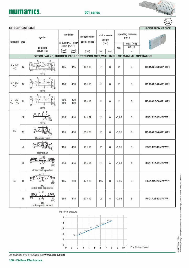
SPECIFICATIONS 15-DIGIT PRODUCT CODE
function type
symbolrated flow
response time
open / closed
pilot pressure
at 23°C(bar)
operating pressureport 1
at 6,3 bar ∆P 1 barl/min (ANR)
min.
max. (PS)
pilot (14)return (12)
air ()1 21 4
2 34 5 (ms) min. max. =
SPOOL VALVE, RUBBER PACKED TECHNOLOGY, WITH IMPULSE MANUAL OPERATOR
2 x 3/2NC
K
14 1210 10
83(12)14
5
4
3
2
1spring
405 415 18 / 18 (a) 8 2 8 R501A2BD0M71WF1
2 x 3/2NO
N
10 1014 12
1483(12)
5 3
1
4 2
spring
400 400 18 / 18 (a) 8 2 8 R501A2BA0M71WF1
2 x 3/2NC - NO
H
14 1010 12
1483(12)
5 3
1
4 2
spring
460450
470450
18 / 18 (a) 8 2 8 R501A2BC0M71WF1
5/2
S1
4 2
3514 83(12)
spring
405 410 14 / 29 2 8 -0,95 8 R501A2B10M71WF1
M 1
4 2
3514(12)83
differential return
405 410 25 / 21 2 8 -0,95 8 R501A2BN0M71WF1
J 1
4 2
3514(12)83
solenoid air
405 410 11 / 11 2 8 -0,95 8 R501A2B40M71WF1
5/3
G 1
4 2
3514(12)83
W1closed centre position
405 410 13 / 12 2 8 -0,95 8 R501A2B60M71WF1
B 1
4 2
3514(12)83
W2centre open to pressure
405 360 17 / 38 2,5 8 -0,95 8 R501A2B70M71WF1
E 1
4 2
3514(12)83
W3centre open to exhaust
365 415 27 / 12 2 8 -0,95 8 R501A2B50M71WF1
501 series
00 21 3 5 7 94 6 8 10
1
2
3
4
5
Pp
P(1)
1,8
2,2
3,1
3,9
2,6
3,5
4,4
Pp = Pilot pressure
P1 = Working pressure
All leaflets are available on: www.asco.com
160 - Fielbus Electronics

0144
0GB
-201
7/R
02A
vaila
bilit
y, d
esig
n an
d sp
ecifi
catio
ns a
re s
ubje
ct to
cha
nge
with
out n
otic
e. A
ll rig
hts
rese
rved
.
How to OrderManifold assemblies kit (Electronic + End plate)
15-DIGIT PRODUCT CODEG 501 A V 3 H 1 0 0 V A36
Thread connection ATEX optionsG = ISO 228/1 2-22 (3GD) IP65X 2-22 (3GD) IP54X 2 (3G) IP54X8 = NPT (contact us) A36 (1) A41 (1) A43 (1)
K = Push-in connectors D36 (2) D41 (2) D43 (2)
D38 (3) D42 (3) D44 (3)
Product series F16 (4) F18 (4) F19 (4)
501 (11 mm valve) (1) Internal pilot W/O DIN Rail Mount(2) DIN Rail Mount
Revision letter (3) External pilot supply from port 14A = Initial release (4) External pilot supply from port 14 and
DIN Rail MountProduct typeV = Valve Manifold Assembly
Electronics8 = 580 Fieldbus ElectronicsD = CHARMs Electronics3 = G3 Fieldbus ElectronicsJ = 25 Pin Sub-D Connector
M = 37 Pin Sub-D ConnectorQ = 19 Pin Round ConnectorT = Terminal Strip 1-32 End Plate Style
V = VerticalNumber of Valve Stations
End Plate Port Size (1-3-5)Used with the first digit «G» or «8»:1 = 1/8 (female thread only)Used with the first digit «K»:H = 6 x 8 mm (push-in connector)
0, 1.. 2
501input modules (1)
(G3/ATEX)max. coils (1)
0,81 W/0,33 W0
321234
580 18580 CHARMs 48
0,7 W/0,8 W25 Pin Sub-D Connector 2237 Pin Sub-D Connector
Terminal Strip 1-3224
19 Pin Round Connector 16
(1) Do not exceed the max. number of pilot solenoid valves authorised.
! Max power consumption per block: 20 W
Configurator - CAD Files
501A = NA/33 I = 9/41 Q = 17 Y = 25B = NA/34 J = 10/42 R = 18 Z = 26C = 3/35 K = 11/43 S = 19 2 = 27D = 4/36 L = 12/44 T = 20 3 = 28E = NA/37 M = 13/45 U = 21 4 = 29F = 6/38 N = 14/46 V = 22 5 = 30G = 7/39 O = 15/47 W = 23 6 = 31H = 8/40 P = 16/48 X = 24 7 = 32
All leaflets are available on: www.asco.com
Fielbus Electronics - 161
501 series

How to OrderSubbases
15-DIGIT PRODUCT CODEH 501 A M S4 2 M 71W 1 0
Thread connection Not useH = Metric threadK = Push-in connectors Interface
1 = High flow
Product series ATEX options501 (11 mm valve) 71W = Standard (zone 2 or zones 2-22)
Revision letterA = Initial release
Product type Wiring optionM = Manifold base M = Plug-inZ = Mid station supply F = 32+ Solenoid Manifold Subbase
Mounting Port connectionS3 = Manifold base, 3 stations, side port, single Z-Board™ B = M7 (female thread only)
D = 2,7 x 4 mm [push-in connector only] (Mid station supply not available)M3 = Manifold base, 3 stations, side port, double Z-Board™
F = 4 x 6 mm [push-in connector only]
S4 = Manifold base, 4 stations, side port, single Z-Board™
M4 = Manifold base, 4 stations, side port, double Z-Board™01
440G
B-2
017/
R02
Ava
ilabi
lity,
des
ign
and
spec
ifica
tions
are
sub
ject
to c
hang
e w
ithou
t not
ice.
All
right
s re
serv
ed.
ll 3G Ex nA llC T4 Gc IP65 X
ll 3D Ex tc lllC T85°C Dc IP65 X
Tech. file
ref.
BP17 2811
1 Luce C
edex Fra
nce
T° am
b C
Max P
. - 8
bar
Option
Year
SERIAL N
°
WARNING : SPECIFIC CONDITIONS OF USE
- SEE INSTRUCTIONS -
-WARNING : DO NOT CONNECT OR DISCONNECT
PLUGS AND SOCKETS WHEN ENERGIZED
WARNING : POTENTIAL ELECTROSTATIC
CHARGING HAZARD - SEE INSTRUCTIONS
501 series
All leaflets are available on: www.asco.com
162 - Fielbus Electronics
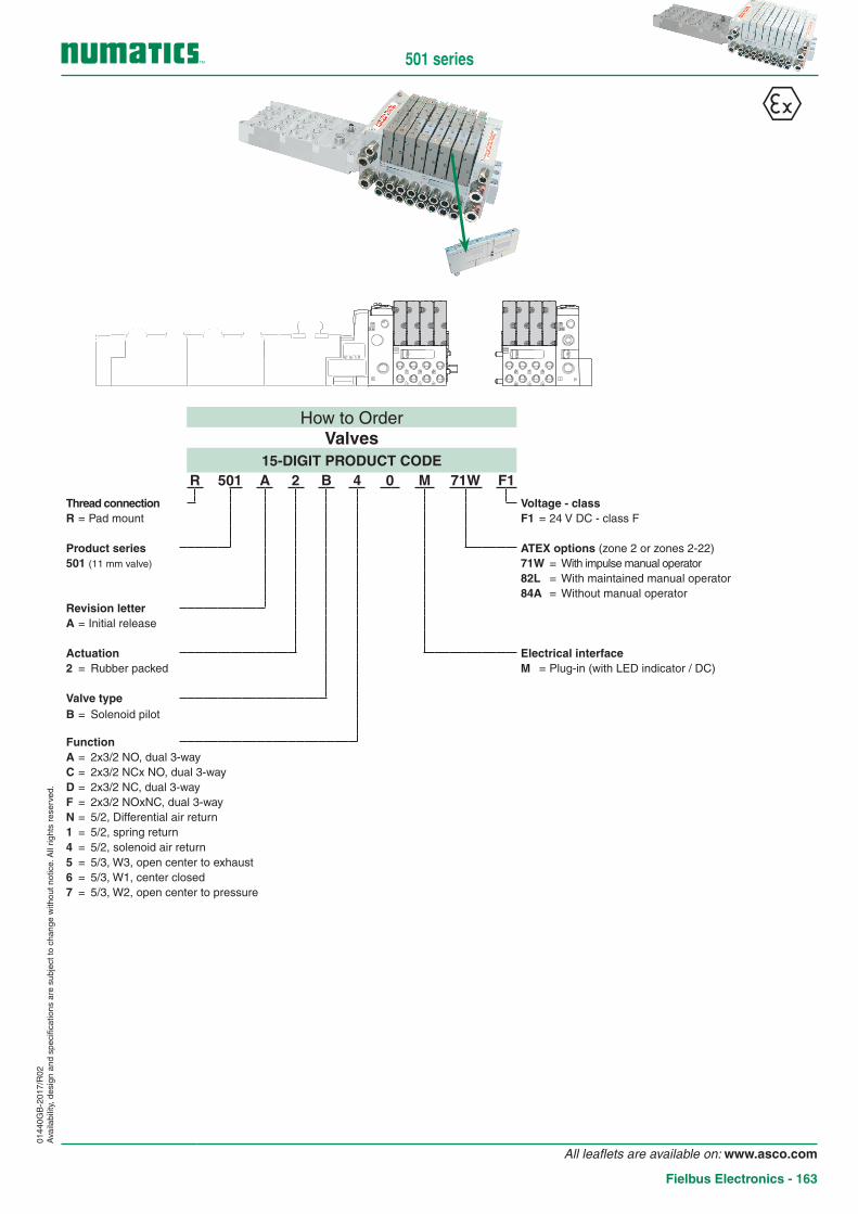
How to OrderValves
15-DIGIT PRODUCT CODER 501 A 2 B 4 0 M 71W F1
Thread connection Voltage - classR = Pad mount F1 = 24 V DC - class F
Product series ATEX options (zone 2 or zones 2-22)501 (11 mm valve) 71W = With impulse manual operator
82L = With maintained manual operator84A = Without manual operator
Revision letterA = Initial release
Actuation Electrical interface2 = Rubber packed M = Plug-in (with LED indicator / DC)
Valve typeB = Solenoid pilot
FunctionA = 2x3/2 NO, dual 3-wayC = 2x3/2 NCx NO, dual 3-wayD = 2x3/2 NC, dual 3-wayF = 2x3/2 NOxNC, dual 3-wayN = 5/2, Differential air return1 = 5/2, spring return4 = 5/2, solenoid air return5 = 5/3, W3, open center to exhaust6 = 5/3, W1, center closed7 = 5/3, W2, open center to pressure
0144
0GB
-201
7/R
02A
vaila
bilit
y, d
esig
n an
d sp
ecifi
catio
ns a
re s
ubje
ct to
cha
nge
with
out n
otic
e. A
ll rig
hts
rese
rved
.
501 series
All leaflets are available on: www.asco.com
Fielbus Electronics - 163

• Used to shut-off pressure to the valve which is mounted above it.
• Allows easy maintenance without the need to shut-off pressure to the whole manifold.
(provided for 2x3/2 NC-NC valve)
Sandwich shut off block
15-DIGIT PRODUCT CODE Description weight (kg)
R501AY428501001 Sandwich shut off block (double) 0,11
(12)(3)(2)(1) (4) (5)(14)
(12)(3)(2)(1) (4) (5)(14)
23,3591,35
26,5
22
109,2
HOW TO ORDER [ATEX options (zone 2 or zones 2-22)]Consult the online configurator - CAD files on: www.asco.com
0144
0GB
-201
7/R
02A
vaila
bilit
y, d
esig
n an
d sp
ecifi
catio
ns a
re s
ubje
ct to
cha
nge
with
out n
otic
e. A
ll rig
hts
rese
rved
.
501 series
! Usable only for internal pilot supply island
! Pay attention to residual pressures
! The valve(s) should not be energised during disassembly
All leaflets are available on: www.asco.com
164 - Fielbus Electronics

ll 3G Ex nA llC T4 Gc IP65 X
ll 3D Ex tc lllC T85°C Dc IP65 X
Tech. file
ref.
BP17 2811
1 Luce C
edex Fra
nce
T° am
b C
Max P
. - 8
bar
Option
Year
SERIAL N
°
WARNING : SPECIFIC CONDITIONS OF USE
- SEE INSTRUCTIONS -
-WARNING : DO NOT CONNECT OR DISCONNECT
PLUGS AND SOCKETS WHEN ENERGIZED
WARNING : POTENTIAL ELECTROSTATIC
CHARGING HAZARD - SEE INSTRUCTIONS
0144
0GB
-201
7/R
02A
vaila
bilit
y, d
esig
n an
d sp
ecifi
catio
ns a
re s
ubje
ct to
cha
nge
with
out n
otic
e. A
ll rig
hts
rese
rved
.
How to OrderG3 Electronics
G3 EP1 00 D 0 71W
Number of I/O Modules00 = 001 = 102 = 203 = 304 = 4
Electronics ProtocolsDN1 = DeviceNet™ED1 = EtherNET/IP DLREM1 = EtherNet ModBus®/TCPEP1 = EtherNet/IP™PT1 = PROFIBUS DPPN1 = PROFINETDS2 = Backplane extension Valve ManifoldDS3 = Backplane extension I/O Assembly
Left MountingD = w/ Backplane extension OutH = w/ Terminating Resistor
ATEX options71W = Version ATEXD45 = 71W + DRM-DIN Rail MountingD46 = 71W + E23-Fieldbus assembly without valvesF20 = 71W + E23-Fieldbus assembly without valves +
DRM-DIN Rail Mounting
Modification0 = Initial release
! 4 modules max. per bloc.ATEX:
501 series
All leaflets are available on: www.asco.com
Fielbus Electronics - 165

0144
0GB
-201
7/R
02A
vaila
bilit
y, d
esig
n an
d sp
ecifi
catio
ns a
re s
ubje
ct to
cha
nge
with
out n
otic
e. A
ll rig
hts
rese
rved
.
ConnectorsAccessory type Designation Code
2 / 5 / 10 m
25 Pin Sub-D Female Connector (500 series) w/ cable
2 m NDB25F22U02MSB3
5 m NDB25F22U05MSB3
10 m NDB25F22U10MSB3
2 / 5 / 10 m
37 Pin Sub-D Female Connector (500 series) w/ cable
2 m NDB37F22U02MSB3
5 m NDB37F22U05MSB3
10 m NDB37F22U10MSB3
19 pin female M23 connector, straight (500 and 2000 series)
w/o cable 88164102
w/ cable 5 m 88164106
19 pin female M23 connector, 90° elbow (500 and 2000 series)
w/o cable 88164105
w/ cable 5 m 88164107
NDB25F22U02MSB3NDB25F22U05MSB3NDB25F22U10MSB3
Pin 1 : whitePin 2 : brownPin 3 : greenPin 4 : yellowPin 5 : greyPin 6 : pinkPin 7 : bluePin 8 : redPin 9 : blackPin 10 : purplePin 11 : grey/pinkPin 12 : red/bluePin 13 : white/greenPin 14 : brown/greenPin 15 : white/yellowPin 16 : yellow/brownPin 17 : white/greyPin 18 : grey/brownPin 19 : white/pinkPin 20 : pink/brownPin 21 : white/bluePin 22 : brown/bluePin 23 : white/redPin 24 : brown/redPin 25 : white/black
NDB37F22U02MSB3NDB37F22U05MSB3NDB37F22U10MSB3
Pin 1 : whitePin 2 : brownPin 3 : greenPin 4 : yellowPin 5 : greyPin 6 : pinkPin 7 : bluePin 8 : redPin 9 : blackPin 10 : purplePin 11 : grey/pinkPin 12 : red/bluePin 13 : white/greenPin 14 : brown/greenPin 15 : white/yellowPin 16 : yellow/brownPin 17 : white/greyPin 18 : grey/brownPin 19 : white/pinkPin 20 : pink/brownPin 21 : white/bluePin 22 : brown/bluePin 23 : white/redPin 24 : brown/redPin 25 : white/black
Pin 26 : brown/blackPin 27 : grey/greenPin 28 : yellow/greyPin 29 : pink/greenPin 30 : yellow/pinkPin 31 : green/bluePin 32 : yellow/bluePin 33 : green/redPin 34 : yellow/redPin 35 : green/blackPin 36 : yellow/blackPin 37 : grey/blue
501 series
All leaflets are available on: www.asco.com
166 - Fielbus Electronics