zimmer segmental system distal femoral surgical technique ... · intro zimmer segmental system...
TRANSCRIPT

Zimmer® Segmental
System
Distal Femoral Surgical Technique
INTRO Zimmer Segmental System Distal Femoral Surgical Technique
INTRO.1
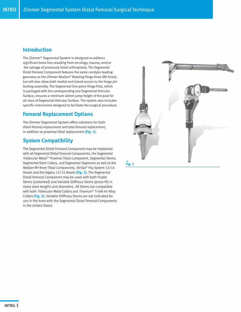
IntroductionThe Zimmer® Segmental System is designed to address significant bone loss resulting from oncology, trauma, and/or the salvage of previously failed arthroplasty. The Segmental Distal Femoral Component features the same condylar-loading geometry as the Zimmer NexGen® Rotating Hinge Knee (RH Knee), but will also allow both medial and lateral access to the hinge pin locking assembly. The Segmental One-piece Hinge Post, which is packaged with the corresponding size Segmental Articular Surface, ensures a minimum 40mm jump-height of the post for all sizes of Segmental Articular Surface. The system also includes specific instruments designed to facilitate the surgical procedure.
Femoral Replacement OptionsThe Zimmer Segmental System offers solutions for both distal femoral replacement and total femoral replacement, in addition to proximal tibial replacement (Fig. 1).
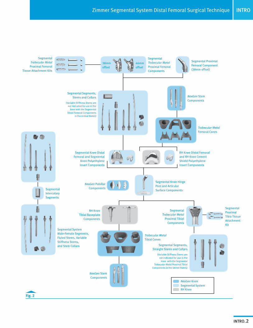
System CompatibilityThe Segmental Distal Femoral Component may be implanted with all Segmental Distal Femoral Components, the Segmental Trabecular Metal™ Proximal Tibial Component, Segmental Stems, Segmental Stem Collars, and Segmental Segments as well as the NexGen RH Knee Tibial Components, VerSys® Hip System 12/14 Heads and the legacy 12/14 Heads (Fig. 2). The Segmental Distal Femoral Component may be used with both Fluted Stems (cemented) and Variable Stiffness Stems (press-fit) in many stem lengths and diameters. All Stems are compatible with both Trabecular Metal Collars and Tivanium® Ti-6Al-4V Alloy Collars (Fig. 2). Variable Stiffness Stems are not indicated for use in the knee with the Segmental Distal Femoral Components in the United States.
Fig. 1
INTROZimmer Segmental System Distal Femoral Surgical Technique
INTRO.2
Fig. 2
NexGen KneeSegmental SystemRH Knee
NexGen Stem Components
Trabecular Metal Femoral Cones
RH Knee Distal Femoral and RH Knee Cement Shield Polyethylene Insert Components
Segmental Knee Hinge Post and Articular Surface Components
Segmental Proximal Tibia Tissue Attachment Kit
Trabecular Metal Tibial Cones
Segmental System Male-Female Segments, Fluted Stems, Variable Stiffness Stems, and Stem Collars
Segmental Intercalary Segments
Segmental Segments, Straight Stems and Collars
(Variable Stiffness Stems are not indicated for use in the
knee with the Segmental Trabecular Metal Proximal Tibial
Components in the United States)
NexGen Stem Components
NexGen Patellar Components
RH Knee Tibial Baseplate
Components
Segmental Trabecular Metal
Proximal Tibial Components
Segmental Knee Distal Femoral and Segmental
Knee Polyethylene Insert Components
Segmental Segments, Stems and Collars
(Variable Stiffness Stems are not indicated for use in the
knee with the Segmental Distal Femoral Components
in the United States)
Segmental Proximal Femoral Component (38mm offset)
Segmental Trabecular Metal Proximal Femoral Components
38mm offset
46mm offset
Segmental Trabecular Metal
Proximal Femoral Tissue Attachment Kits
INTRO
TOC.1
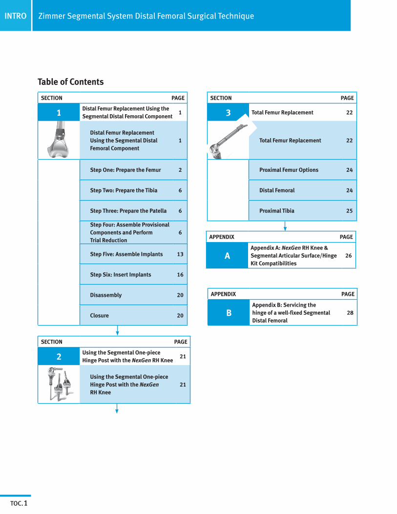
SECTION PAGE
1 Distal Femur Replacement Using the Segmental Distal Femoral Component
1
Distal Femur Replacement Using the Segmental Distal Femoral Component
1
Step One: Prepare the Femur 2
Step Two: Prepare the Tibia 6
Step Three: Prepare the Patella 6
Step Four: Assemble Provisional Components and Perform Trial Reduction
6
Step Five: Assemble Implants 13
Step Six: Insert Implants 16
Disassembly 20
Closure 20
Zimmer Segmental System Distal Femoral Surgical Technique
Table of Contents
APPENDIX PAGE
AAppendix A: NexGen RH Knee & Segmental Articular Surface/Hinge Kit Compatibilities
26
SECTION PAGE
2 Using the Segmental One-piece Hinge Post with the NexGen RH Knee
21
Using the Segmental One-piece Hinge Post with the NexGen RH Knee
21
SECTION PAGE
3 Total Femur Replacement 22
Total Femur Replacement 22
Proximal Femur Options 24
Distal Femoral 24
Proximal Tibia 25
APPENDIX PAGE
BAppendix B: Servicing the hinge of a well-fixed Segmental Distal Femoral
28
SECTION
1
1
Distal Femur Replacement Using the Segmental Distal Femoral Component
These conditions may place excessive demand/ severe loading on the polyethylene insert (box) component of the Segmental Distal Femoral Construct:• Neuropathic Athropathy (Charcot’s knee)
• Muscle deficiencies (quadriceps insufficiency or previous patellar tendon/tibial tubercle rupture)
• Refusal to modify postoperative physical activities
• Morbid obesity (Body Mass Index >39)
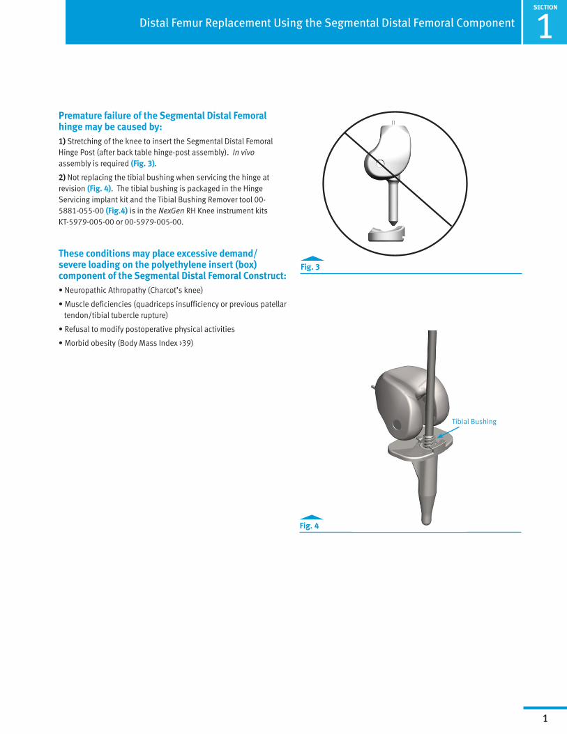
Premature failure of the Segmental Distal Femoral hinge may be caused by: 1) Stretching of the knee to insert the Segmental Distal Femoral Hinge Post (after back table hinge-post assembly). In vivo assembly is required (Fig. 3).
2) Not replacing the tibial bushing when servicing the hinge at revision (Fig. 4). The tibial bushing is packaged in the Hinge Servicing implant kit and the Tibial Bushing Remover tool 00-5881-055-00 (Fig.4) is in the NexGen RH Knee instrument kits KT-5979-005-00 or 00-5979-005-00.
Fig. 3
Fig. 4
Tibial Bushing
1SECTION
2
Distal Femur Replacement Using the Segmental Distal Femoral Component
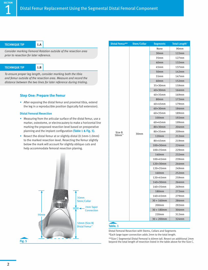
Table. 1
Distal Femoral Resection with Stems, Collars and Segments *Each large taper connection adds 2mm to the total length.
**Size C Segmental Distal Femoral is 60mm tall. Resect an additional 2mm beyond the total length of resection listed in the table above for the Size C.Fig. 5
Distal Femur** Stem/Collar Segments Total Length*
Size B58mm** 30mm
None 90mm
30mm 122mm
35mm 127mm
40mm 132mm
45mm 137mm
50mm 142mm
55mm 147mm
60mm 152mm
35+30mm 159mm
40+30mm 164mm
40+35mm 169mm
80mm 172mm
40+45mm 179mm
60+30mm 184mm
60+35mm 189mm
100mm 192mm
60+45mm 199mm
80+30mm 204mm
80+35mm 209mm
120mm 212mm
80+45mm 219mm
100+30mm 224mm
100+35mm 229mm
140mm 232mm
100+45mm 239mm
120+30mm 244mm
120+35mm 249mm
160mm 252mm
120+45mm 259mm
140+30mm 264mm
140+35mm 269mm
180mm 272mm
140+45mm 279mm
30 + 160mm 284mm
200mm 292mm
30 + 180mm 304mm
220mm 312mm
30 + 200mm 324mm
Step One: Prepare the Femur
• After exposing the distal femur and proximal tibia, extend the leg in a reproducible position (typically full extension).
Distal Femoral Resection
• Measuring from the articular surface of the distal femur, use a marker, osteotome, or electrocautery to make a horizontal line marking the proposed resection level based on preoperative planning and the implant configuration (Table 1 & Fig. 5).
• Resect the distal femur at or slightly distal (0.5mm-1.0mm) to the marked resection level. Resecting the femur slightly below the mark will account for slightly oblique cuts and help accommodate femoral resection planing.
TECHNIQUE TIP 1.A
Consider marking Femoral Rotation outside of the resection area prior to resection for later reference.
TECHNIQUE TIP 1.B
To ensure proper leg length, consider marking both the tibia and femur outside of the resection area. Measure and record the distance between the two lines for later reference during trialing.
90mm
58mm (Size B) Distal Femur**
30mmStem/Collar
2mm Taper Connection

SECTION
1
3
Distal Femur Replacement Using the Segmental Distal Femoral Component
Instruments
Table. 2b
Recommended reamer diameters
Ream the Femoral Canal
• Ream the femoral canal until the reamer contacts cortical bone in the isthmus. For a straight stem, use the straight reamers from the VerSys Hip System. For a bowed stem, flexible reamers from the Pressure Sentinel® Intramedullary Reaming System are recommended: use the Pressure Sentinel Reamer Expanded Hip Set (00-2228-000-03) or the ZMR® Flexible Reamer Set (00-9975-000-11).
• If preferred, the flexible reamers can also be used for a straight Variable Stiffness Stem to allow for point contact in the canal. The intramedullary lengths of the stems are listed in the chart to the right (Table 2a). Ream to a depth greater than the intramedullary length to allow proper seating of the stem collar on the cortical bone and placement of a cement restrictor if using a fluted stem.
Variable Stiffness Straight Stems
• For optimal fit, the Segmental 3/4mm Reamers may be used.
• Flexible reamers may be used to allow for point contact in the canal.
• If insertion is difficult, consider reaming an additional time with the final reamer diameter used.
Notes:
— The diameters indicated for the Segmental Variable Stiffness Stems represent the actual outer diameters of the stems, which include the height of the splines. The diameter of the reamed hole should be 0.5mm smaller than the labeled stem size to provide for apposition of the distal splines with the femoral canal (Table 2b).
— When using a bowed variable stiffness stem it may be necessary to ream the intramedullary canal to a diameter equal to or slightly greater than the diameter of the stem to accommodate any difference between the bow of the stem prosthesis and the anatomy of the patient.
— The diameters indicated for the Segmental Fluted Stems represent the actual outer diameters of the stem. Therefore, the diameter of the definitive stem should be 2mm smaller than that of the largest reamer used to ream the canal to allow for an adequate cement mantle (Table 2b).
Stem Size Minimum Ream Diameter (Fluted)
Minimum Ream Diameter
(Variable Stiffness)
9mm 11mm 8.5mm
10mm 12mm 9.5mm
11mm 13mm 10.5mm
12mm 14mm 11.5mm
13mm 15mm 12.5mm
14mm 16mm 13.5mm
15mm 17mm 14.5mm
16mm 18mm 15.5mm
17mm 19mm 16.5mm
18mm 20mm 17.5mm
19mm 21mm 18.5mm
Table. 2a
Stem Types and Lengths
Stem Diameter (mm)
9 10 11 12 13 14 15 16 17 18 19
Ste
m IM
Le
ngth
Ste
m T
ype
130mm Straight (Fluted & Variable Stiffness)
190mm Straight (Fluted)
190mm Bowed (Variable Stiffness)
250mm Bowed (Fluted)
Segmental 3/4mm Reamer
(See ZSS Profiler)KT-5853-014-00
ZMR System Flexible Reamer
(See ZSS Profiler)00-9975-000-11
Pressure Sentinel
IM Reamer (See ZSS Profiler)00-2228-000-03
VerSys Hip Reamer (See ZSS Profiler) KT-5853-013-00 00-7899-073-00

1SECTION
4
Distal Femur Replacement Using the Segmental Distal Femoral Component
Instruments
Plane the Femoral Bone
• Thread the appropriately sized Segmental Planer Pilot (130mm long) for the stem diameter selected onto the Femoral/Tibial Planer (Fig. 6).
• If the anatomy requires the use of a shorter planer pilot, use the 75mm length Segmental Planer Pilots. If the canal is bowed, use the shorter Planer Pilots from the Segmental Variable Stiffness Stem instrument kit (KT-5853-008-00). A Planer Pilot 1-2mm smaller than the stem diameter chosen can be used to facilitate insertion into a curved medullary canal (Table 3). Attach the assembly to a power driver with a Zimmer adapter. Then plane the resected distal femur until the cortical bone is smooth and flat.
• To aid in removing the Planer Pilot from the Planer, insert the pin on the Segmental Collar Provisional Sizer through the cross-hole and, while securing the noncutting end of the planer, turn the shank counterclockwise.
Fig. 6
Planer
Planer Pilot
Table. 3
Recommended Planer Pilot Diameters
Stem Size Planer Pilot Diameter (Fluted)
Planer Pilot Diameter
(Variable Stiffness)
9mm 9mm 8mm
10mm 10mm 9mm
11mm 11mm 10mm
12mm 12mm 11mm
13mm 13mm 12mm
14mm 14mm 13mm
15mm 15mm 14mm
16mm 16mm 15mm
17mm 17mm 16mm
18mm 18mm 17mm
19mm 19mm 18mm
Segmental Planer Pilot
(See ZSS Profiler)00-5851-070-XX
Segmental Planer
5100-00-052
Segmental Collar Provisional Sizer00-5853-056-10

SECTION
1
5
Distal Femur Replacement Using the Segmental Distal Femoral Component
Instruments
Counterbore the Femoral Canal (Variable Stiffness Stems Only)
• The full diameter of a Variable Stiffness Stem proximal to the splines will be 0.5mm greater than the reamed diameter of the femoral canal. Counterboring this proximal portion is required for proper insertion of the stem in the intramedullary canal.
• Thread the appropriate size Counterbore Reamer Tip into the Counterbore Stop Plate (Fig. 7).
• Then insert the assembly into a power driver. Insert the pin on the Segmental Collar Provisional Sizer through the cross-hole of the Counterbore Reamer Tip and turn the collar to tightly secure it to the Counterbore Stop Plate (Fig. 8).
• Insert the assembly into the reamed canal and counterbore the proximal canal (Fig. 9). The Counterbore Stop Plate will serve as a stop when the appropriate depth is achieved. Do not over ream or elongate the hole.
Counterbore Reamer Stop Plate
Counterbore Reamer Tip
Counterbore Reamer Tip
Segmental Collar Provisional Sizer
Fig. 7
Fig. 8
Fig. 9
Counterbore Reamer Tip
(See ZSS Profiler)00-5851-073-XX
Counterbore Reamer Stop Plate00-5851-073-01
Segmental Collar Provisional Sizer00-5853-056-10
1SECTION
6
Distal Femur Replacement Using the Segmental Distal Femoral Component
Instruments
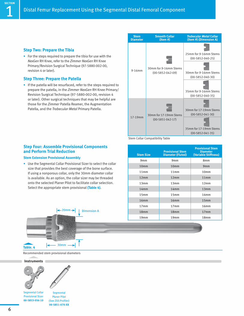
30mm
20mm Dimension A
Step Two: Prepare the Tibia• For the steps required to prepare the tibia for use with the
NexGen RH Knee, refer to the Zimmer NexGen RH Knee Primary/Revision Surgical Technique (97-5880-002-00, revision 4 or later).
Step Three: Prepare the Patella• If the patella will be resurfaced, refer to the steps required to
prepare the patella, in the Zimmer NexGen RH Knee Primary/Revision Surgical Technique (97-5880-002-00, revision 4 or later). Other surgical techniques that may be helpful are those for the Zimmer Patella Reamer, the Augmentation Patella, and the Trabecular Metal Primary Patella.
Step Four: Assemble Provisional Components and Perform Trial ReductionStem Extension Provisional Assembly
• Use the Segmental Collar Provisional Sizer to select the collar size that provides the best coverage of the bone surface. If using a nonporous collar, only the 30mm diameter collar is available. As an option, the collar sizer may be threaded onto the selected Planer Pilot to facilitate collar selection. Select the appropriate stem provisional (Table 4).
Table. 4
Recommended stem provisional diameters
Stem SizeProvisional Stem Diameter (Fluted)
Provisional Stem Diameter
(Variable Stiffness)
9mm 9mm 8mm
10mm 10mm 9mm
11mm 11mm 10mm
12mm 12mm 11mm
13mm 13mm 12mm
14mm 14mm 13mm
15mm 15mm 14mm
16mm 16mm 15mm
17mm 17mm 16mm
18mm 18mm 17mm
19mm 19mm 18mm
Stem Diameter
Smooth Collar (Item #)
Trabecular Metal Collar (Item #) (Dimension A)
9-16mm30mm for 9-16mm Stems
(00-5852-042-09)
25mm for 9-16mm Stems (00-5852-040-25)
30mm for 9-16mm Stems (00-5852-040-30)
35mm for 9-16mm Stems (00-5852-040-35)
17-19mm30mm for 17-19mm Stems
(00-5851-042-17)
30mm for 17-19mm Stems (00-5852-041-30)
35mm for 17-19mm Stems (00-5852-041-35)
Stem Collar Compatibility Table
Segmental Planer Pilot
(See ZSS Profiler)00-5851-070-XX
Segmental Collar Provisional Sizer00-5853-056-10

SECTION
1
7
Distal Femur Replacement Using the Segmental Distal Femoral Component
Instruments
TECHNIQUE TIP 1.C
Check the fit of the Stem Extension Provisional Assembly by inserting it into the reamed canal. For a bowed canal, it may be necessary to perform additional reaming, possibly causing the next smaller stem size to be utilized.
• Confirm that the stem and stem collar sizes are compatible (Table 4). Then thread the Segmental Collar Provisional onto the selected Segmental Stem Provisional (Fig. 10).
Notes: — The diameters of the Segmental Stem Provisionals
represent the actual diameters of the stems, i.e. a 14mm stem provisional has a nominal 14mm outer diameter.
— The same Segmental Straight Stem Provisionals (130mm) are used for both the 130mm Segmental Fluted Straight Stem and the 130mm Variable Stiffness Straight Stem, although, when trialing, a diameter 1mm less than the stem to be implanted is recommended for the Segmental Variable Stiffness stems.
Segmental Stem Provisional Bowed (See ZSS Profiler)00-5853-054-XX
Segmental Stem Provisional Straight
(See ZSS Profiler) 00-5853-05X-XX
Collar Provisional (See ZSS Profiler)00-5853-056-XX
Fig. 10
Hole for Threading Collar
Anterversion Pockets
Threaded Extraction Hole
Provisional Stem
Threaded Provisional Collar

1SECTION
8
Distal Femur Replacement Using the Segmental Distal Femoral Component
Femoral Provisional Assembly and Insertion
• After verifying that all sizes are correct, assemble the provisional femoral components. The components can be assembled either on the back table or in vivo. For back-table assembly, place the Segmental Distal Femoral Provisional into the Segmental Condyle Impactor. If using a segment provisional, place the male taper into the female taper of the distal femoral provisional. Using the appropriate Segmental Implant/Provisional Male or Female Impactor and the Universal Impactor Handle, impact the segment provisional onto the distal femur. Next attach the stem provisional to the segment provisional or femoral provisional using the appropriate impactor. Ensure that all tabs on the provisional components are properly engaged in the corresponding pockets. Use gauze to protect the stem tip and impact with a mallet.
• Alternatively, the femoral provisionals may be assembled sequentially in vivo. If necessary, the Universal Impactor Handle can be threaded into the base of the Segmental Condyle Impactor (Fig. 11).
• Insert the femoral provisional assembly into the femoral canal and evaluate the fit. If necessary to achieve full seating, use the Segmental Condyle Impactor, the Universal Impactor Handle, and a mallet to lightly impact the distal end of the Segmental Distal Femoral Provisional (Fig. 12). Evaluate the fit of the stem collar on the bone surface to determine if the stem is fully seated. Assess the orientation of the distal femoral provisional and determine whether a rotation adjustment will be necessary. If desired, the femoral component can be slightly externally rotated based on the anterior femur and linea aspera to facilitate patellar tracking.
• If a bowed stem is being used, mark the femoral bone in line with the alignment slot on the mediolateral side of the Segmental Bowed Stem Provisional to provide a locator for proper orientation of the implant (Fig. 12).
Fig. 11
Segmental Stem Provisional Bowed (See ZSS Profiler)00-5853-054-XX
Segmental Stem Provisional Straight
(See ZSS Profiler) 00-5853-05X-XX
Segmental Implant/Provisional Male Taper Impactor
(Stem Impactor)00-5851-080-00
Segmental Implant/Provisional Female
Taper Impactor (Segment Impactor)
00-5851-074-02
Segmental Distal Femoral Provisional
(See ZSS Profiler)00-5851-01X-XX
Segmental Condyle Impactor
00-5851-074-00
Segment Provisional
(See ZSS Profiler)KT-5853-004-00
Universal Handle6216-01-125
Collar Provisional (See ZSS Profiler)00-5853-056-XX
Fig. 12
Anteversion Pockets
Alignment Slot
Mallet00-0155-002-00
Instruments
SECTION
1
9
Distal Femur Replacement Using the Segmental Distal Femoral Component
Instruments
Segmental Stem Provisional Bowed (See ZSS Profiler) 00-5853-054-XX
Segmental Stem Provisional Straight
(See ZSS Profiler) 00-5853-05X-XX
Segment Provisional
(See ZSS Profiler)KT-5853-004-00
Tab
Pockets
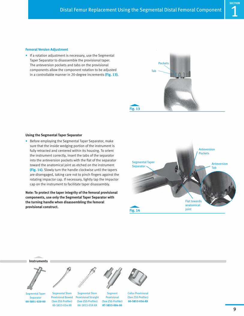
Femoral Version Adjustment
• If a rotation adjustment is necessary, use the Segmental Taper Separator to disassemble the provisional taper. The anteversion pockets and tabs on the provisional components allow the component rotation to be adjusted in a controllable manner in 20-degree increments (Fig. 13).
Using the Segmental Taper Separator
• Before employing the Segmental Taper Separator, make sure that the inside wedging portion of the instrument is fully retracted and centered within its housing. To orient the instrument correctly, insert the tabs of the separator into the anteversion pockets with the flat of the separator toward the anatomical joint as etched on the instrument (Fig. 14). Slowly turn the handle clockwise until the tapers are disengaged, taking care not to pinch fingers against the rotating impactor cap. If necessary, lightly tap the impactor cap on the instrument to facilitate taper disassembly.
Note: To protect the taper integrity of the femoral provisional components, use only the Segmental Taper Separator with the turning handle when disassembling the femoral provisional construct.
Fig. 13
Fig. 14
Segmental Taper Separator
Anteversion Pockets
Anteversion Tab
Flat towards anatomical joint
Segmental Taper Separator
00-5851-020-00
Collar Provisional (See ZSS Profiler)00-5853-056-XX

1SECTION
10
Distal Femur Replacement Using the Segmental Distal Femoral Component
Instruments
Segmental Stem Provisional Bowed (See ZSS Profiler) 00-5853-054-XX
Segmental Stem Provisional Straight
(See ZSS Profiler) 00-5853-05X-XX
Collar Provisional (See ZSS Profiler)00-5853-056-XX
Segmental Distal Femoral
Segmental Articular Surface
RH Knee Tibial
Tibial Provisional Assembly and Insertion
• Assemble the NexGen RH Knee Tibial Provisional Components and NexGen Stem Extension Provisional, if applicable. Use the provisionals from the RH Knee Articular Surface Provisional Instrument Set (Kit# 5979-04). Remember that the size on the femoral provisional must exactly match the size of the articular surface provisional. The size on the tibial provisional must be appropriate for the size of the femoral provisional and tibial articular surface provisional (Table 5).
Note: When using a large tibia component paired with a small femoral component, some portion of the tibia base plate will be visible under the articulating surface. This is normal.
• Insert the tibial provisional construct into the tibial canal, and then insert the appropriate size articular surface provisional. Place the knee through a full range of motion to evaluate soft tissue tension and knee stability. A thicker articular surface provisional should be used if necessary to correctly balance the knee.
Note: The Segmental Distal Femoral Component and the RH Knee Tibial Components are linked, forcing the tibia to be in alignment directly under the femur (on the mechanical axis) by virtue of the one-piece hinge post that links the femoral and tibial components.
Segmental Distal Femoral Size
B C
RH KneeTibialSize
1 B/123456 C/123456
2 B/123456 C/123456
3 B/123456 C/123456
4 B/123456 C/123456
5 B/123456 C/123456
6 B/123456 C/123456
Table. 5
Interchangeability Chart: Segmental Knee System (using an RH Knee Tibial Component)
Segmental Distal Femoral Provisional
(See ZSS Profiler)00-5851-01X-0X
RH Knee Articular Surface Provisional
(See ZSS Profiler)00-5881-0XX-XX
NexGen RH Knee Tibial Provisional (See ZSS Profiler)00-5881-XXX-XX
Straight Stem Extension Provisional
(See ZSS Profiler)00-5989-010-10
Offset Stem Extension Provisional
(See ZSS Profiler)00-5987-020-11
Segmental Hinge Post Provisional
(See ZSS Profiler)00-5851-01X-12
SECTION
1
11
Distal Femur Replacement Using the Segmental Distal Femoral Component
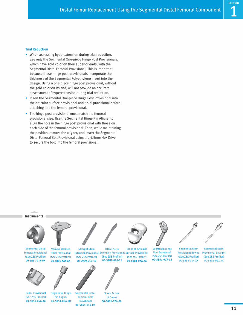
Trial Reduction
• When assessing hyperextension during trial reduction, use only the Segmental One-piece Hinge Post Provisionals, which have gold color on their superior ends, with the Segmental Distal Femoral Provisional. This is important because these hinge post provisionals incorporate the thickness of the Segmental Polyethylene Insert into the design. Using a one-piece hinge post provisional, without the gold color on its end, will not provide an accurate assessment of hyperextension during trial reduction.
• Insert the Segmental One-piece Hinge Post Provisional into the articular surface provisional and tibial provisional before attaching it to the femoral provisional.
• The hinge post provisional must match the femoral provisional size. Use the Segmental Hinge Pin Aligner to align the hole in the hinge post provisional with those on each side of the femoral provisional. Then, while maintaining the position, remove the aligner, and insert the Segmental Distal Femoral Bolt Provisional using the 4.5mm Hex Driver to secure the bolt into the femoral provisional.
Segmental Hinge Pin Aligner
00-5851-084-00
Segmental Distal Femoral Bolt Provisional
00-5851-012-07
Screw Driver (4.5mm)
00-5881-026-00
Instruments
Segmental Stem Provisional Bowed (See ZSS Profiler) 00-5853-054-XX
Segmental Stem Provisional Straight
(See ZSS Profiler) 00-5853-05X-XX
Collar Provisional (See ZSS Profiler)00-5853-056-XX
Segmental Distal Femoral Provisional
(See ZSS Profiler)00-5851-01X-0X
RH Knee Articular Surface Provisional
(See ZSS Profiler)00-5881-0XX-XX
NexGen RH Knee Tibial Provisional (See ZSS Profiler)00-5881-XXX-XX
Straight Stem Extension Provisional
(See ZSS Profiler)00-5989-010-10
Offset Stem Extension Provisional
(See ZSS Profiler)00-5987-020-11
Segmental Hinge Post Provisional
(See ZSS Profiler)00-5851-01X-12

1SECTION
12
Distal Femur Replacement Using the Segmental Distal Femoral Component
Instruments
• The femoral provisional rotation should be evaluated and adjusted, if necessary. Leg holders should not be used during the assembly process.
• Insert the appropriate patellar provisional if patellar resurfacing is being performed. Conduct a complete evaluation of range of motion. Evaluate the patellar tracking, and palpate the posterior soft tissues to ensure that there is not excessive tension. To avoid causing damage to nerve and vascular structures, do not pull too hard on the leg. Assess the rotation of the limb and, if necessary, adjust the rotation of the components. Then perform any necessary soft tissue releases.
Provisional Disassembly
• Remove the patellar provisional, if used, Segmental Distal Femoral Bolt Provisional, Segmental One-piece Hinge Post Provisional, and articular surface provisional. Manually attempt to remove the femoral provisional, segment provisional, if used, and the stem provisional. If these components cannot be removed manually, use the Segmental Taper Separator to loosen the taper between the stem and the femoral provisional or segment provisional, if used. Thread the Provisional Slaphammer Adaptor (Fig. 15) onto the slaphammer and thread it into the stem provisional. Impact the slaphammer to remove the stem provisional. Then remove the tibial base plate provisional and associated extension provisional, if used.
Fig. 15
Provisional Slaphammer Adapter (two grooves)
Implant Slaphammer Adapter (one groove)
Segmental Distal Femoral Provisional
(See ZSS Profiler) 00-5851-01X-0X
Segment Provisional
(See ZSS Profiler)KT-5853-004-00
NexGen RH Knee Tibial Provisional (See ZSS Profiler)00-5881-XXX-XX
Segmental Distal Femoral Bolt Provisional
00-5851-012-07
Screw Driver (4.5mm)
00-5881-026-00
Straight Stem Extension Provisional
(See ZSS Profiler)00-5989-010-10
Offset Stem Extension Provisional
(See ZSS Profiler)00-5987-020-11
Segmental Taper Separator
00-5851-020-00
Provisional Slaphammer
Adapter00-5851-097-12
Segmental Hinge Post Provisional
(See ZSS Profiler)00-5851-01X-12
Slaphammer00-6551-006-00

SECTION
1
13
Distal Femur Replacement Using the Segmental Distal Femoral Component
Instruments
Collar Alignment Tab
Pocket on Trabecular Metal Collar
Step Five: Assemble ImplantsNotes:
— Remove any debris from tapers prior to assembly of tapered components.
— If implanting the Variable Stiffness Stem/Collar/Segment/Distal Femoral assembly separately, DO NOT impact the segment or stem to the distal femur at this time. Please proceed to the next section “Stem Extension Assembly.”
Distal Femoral Assembly
• Before assembling the final components, verify the accuracy of the implants selected and the compatibility of all component sizes (Intro 2 Compatibility Chart & Table 6).
• Assemble the femoral and tibial components as described in the provisional assembly step before mixing the cement. If segments will be used, rest the distal condyles of the femoral component on the Segmental Condyle Impactor (Fig. 16). Align the anteversion tabs, and then use the Segmental Implant/Provisional Male or Female Impactor, the Universal Impactor Handle, and a mallet to solidly impact the segment into the femoral component.
Note: Avoid notching, scratching, or directly striking the implants during assembly
• With the femoral component resting on the Segmental Condyle Impactor on the back table, ensure that all anteversion tabs are properly aligned. For a Fluted stem, protect the end of the stem with gauze during impaction. Then use a mallet to solidly impact the stem into the femoral component or segment.
• When impacting the Variable Stiffness Stem into the distal femoral component or segment, the Variable Stiffness Stem Impaction Sleeve must be used to avoid damaging the prongs on the Variable Stiffness Stem tip.
• Slide the Variable Stiffness Stem Impaction Sleeve over the stem until the notches on the sleeve capture the collar alignment tabs on the stem base. Use a two-pound mallet to solidly strike the impaction head of the sleeve. This will impact the stem into the femoral component or segment. Use cementing technique described for Fluted stems (Fig. 17) to cement the collar to the Variable Stiffness Stem.
Segmental Femoral Size
B C
RH KneeTibialSize
1 B/123456 C/123456
2 B/123456 C/123456
3 B/123456 C/123456
4 B/123456 C/123456
5 B/123456 C/123456
6 B/123456 C/123456
Table. 6
Interchangeability Chart: Segmental Knee System (using an RH Knee Tibial Component)
Fig. 16
Anteversion Tabs
Femoral Condyle Impactor
Fig. 17
Segmental Implant/Provisional Male Taper Impactor
(Stem Impactor)00-5851-080-00
Segmental Implant/Provisional Female
Taper Impactor (Segment Impactor)
00-5851-074-02
Segmental Condyle Impactor
00-5851-074-00
Variable Stiffness Stem Impaction
Sleeve 00-5853-074-05
Universal Handle6216-01-125
Mallet00-0155-002-00
1SECTION
14
Distal Femur Replacement Using the Segmental Distal Femoral Component
30mm
20mm Dimension A
Table. 7
Stem Collar Compatibility Chart
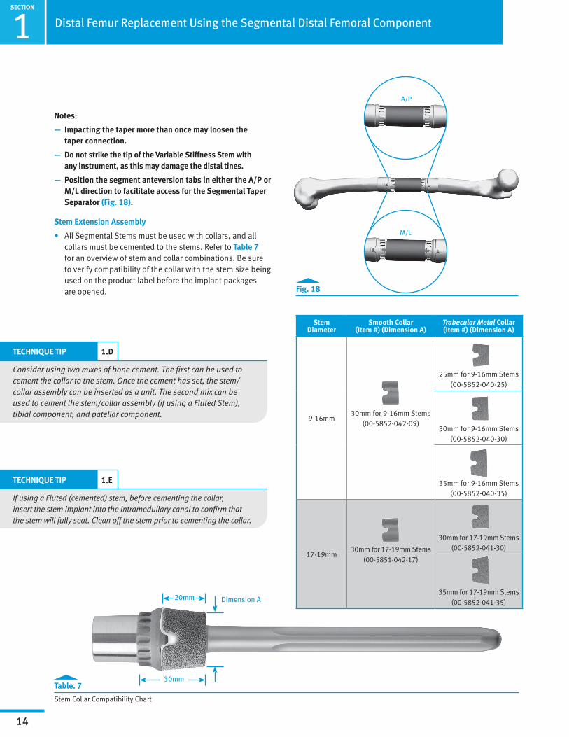
Fig. 18
Notes:
— Impacting the taper more than once may loosen the taper connection.
— Do not strike the tip of the Variable Stiffness Stem with any instrument, as this may damage the distal tines.
— Position the segment anteversion tabs in either the A/P or M/L direction to facilitate access for the Segmental Taper Separator (Fig. 18).
Stem Extension Assembly
• All Segmental Stems must be used with collars, and all collars must be cemented to the stems. Refer to Table 7 for an overview of stem and collar combinations. Be sure to verify compatibility of the collar with the stem size being used on the product label before the implant packages are opened.
TECHNIQUE TIP 1.D
Consider using two mixes of bone cement. The first can be used to cement the collar to the stem. Once the cement has set, the stem/collar assembly can be inserted as a unit. The second mix can be used to cement the stem/collar assembly (if using a Fluted Stem), tibial component, and patellar component.
TECHNIQUE TIP 1.E
If using a Fluted (cemented) stem, before cementing the collar, insert the stem implant into the intramedullary canal to confirm that the stem will fully seat. Clean off the stem prior to cementing the collar.
M/L
A/P
Stem Diameter
Smooth Collar (Item #) (Dimension A)
Trabecular Metal Collar (Item #) (Dimension A)
9-16mm30mm for 9-16mm Stems
(00-5852-042-09)
25mm for 9-16mm Stems (00-5852-040-25)
30mm for 9-16mm Stems (00-5852-040-30)
35mm for 9-16mm Stems (00-5852-040-35)
17-19mm30mm for 17-19mm Stems
(00-5851-042-17)
30mm for 17-19mm Stems (00-5852-041-30)
35mm for 17-19mm Stems (00-5852-041-35)

SECTION
1
15
Distal Femur Replacement Using the Segmental Distal Femoral Component
Collar Alignment Tab
Pocket on Trabecular Metal Collar
Fig. 19
• For a Fluted stem, apply cement in the doughy state to the base/taper end of the stem. Then slide the stem collar over the stem and advance it to the shank area where cement was applied. Clean off excess cement as the collar is advanced. Care should be taken to prevent cement from contacting the taper, the anteversion adjustment pockets, and the external surfaces of Trabecular Metal Material. Collars must be assembled to the stem with the pockets toward the anatomical joint and engaged into the tabs on the stem (Fig. 19). Allow the cement to fully harden before inserting into the Distal Femoral Component.
Proximal Tibial Assembly
• To assemble the NexGen RH Knee Tibial Component, refer to the Zimmer NexGen RH Knee Primary/Revision Surgical Technique (97-5880-002-00, revision 4 or later).
• If the Segmental Proximal Tibial Component will be used, refer to the Zimmer Segmental System Trabecular Metal Proximal Tibial Component Surgical Technique (97-5850-006-00).
1SECTION
16
Distal Femur Replacement Using the Segmental Distal Femoral Component
Instruments
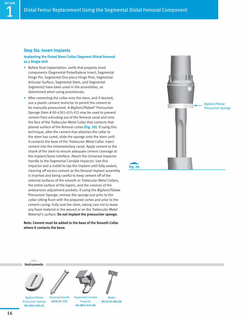
Step Six: Insert ImplantsImplanting the Fluted Stem/Collar/Segment/Distal Femoral as a Single Unit
• Before final implantation, verify that properly sized components (Segmental Polyethylene Insert, Segmental Hinge Pin, Segmental One-piece Hinge Post, Segmental Articular Surface, Segmental Stem, and Segmental Segments) have been used in the assemblies, as determined when using provisionals.
• After cementing the collar onto the stem, and if desired, use a plastic cement restrictor to permit the cement to be manually pressurized. A Bigliani/Flatow® Pressurizer Sponge (item # 00-4301-035-01) may be used to prevent cement from extruding out of the femoral canal and onto the face of the Trabecular Metal Collar that contacts that planed surface of the femoral cortex (Fig. 20). If using this technique, after the cement that attaches the collar to the stem has cured, slide the sponge onto the stem until it contacts the base of the Trabecular Metal Collar. Inject cement into the intramedullary canal. Apply cement to the shank of the stem to ensure adequate cement coverage at the implant/bone interface. Attach the Universal Impactor Handle to the Segmental Condyle Impactor. Use this impactor and a mallet to tap the implant until fully seated, cleaning off excess cement as the femoral implant assembly is inserted and being careful to keep cement off of the external surfaces of the smooth or Trabecular Metal Collars, the entire surface of the tapers, and the crevices of the anteversion adjustment pockets. If using the Bigliani/Flatow Pressurizer Sponge, remove the sponge just prior to the collar sitting flush with the prepared cortex and prior to the cement curing. Fully seat the stem, taking care not to leave any foam material in the wound or on the Trabecular Metal Material’s surface. Do not implant the pressurizer sponge.
Note: Cement must be added to the base of the Smooth Collar where it contacts the bone.
Segmental Condyle Impactor
00-5851-074-00
Universal Handle6216-01-125
Mallet00-0155-002-00
Bigliani/Flatow Pressurizer Sponge
00-4301-035-01
Fig. 20
Bigliani/Flatow Pressurizer Sponge
SECTION
1
17
Distal Femur Replacement Using the Segmental Distal Femoral Component
Instruments
Fig. 21
Other Components
• To implant the tibial component, refer to the NexGen RH Knee Primary/Revision Surgical Technique (97-5880-002-00, revision 4 or later). To implant the patellar component, refer to “Step Three: Prepare the Patella.” The articular surface provisional may be inserted and the knee placed in extension while the cement is setting to maintain compression on the components.
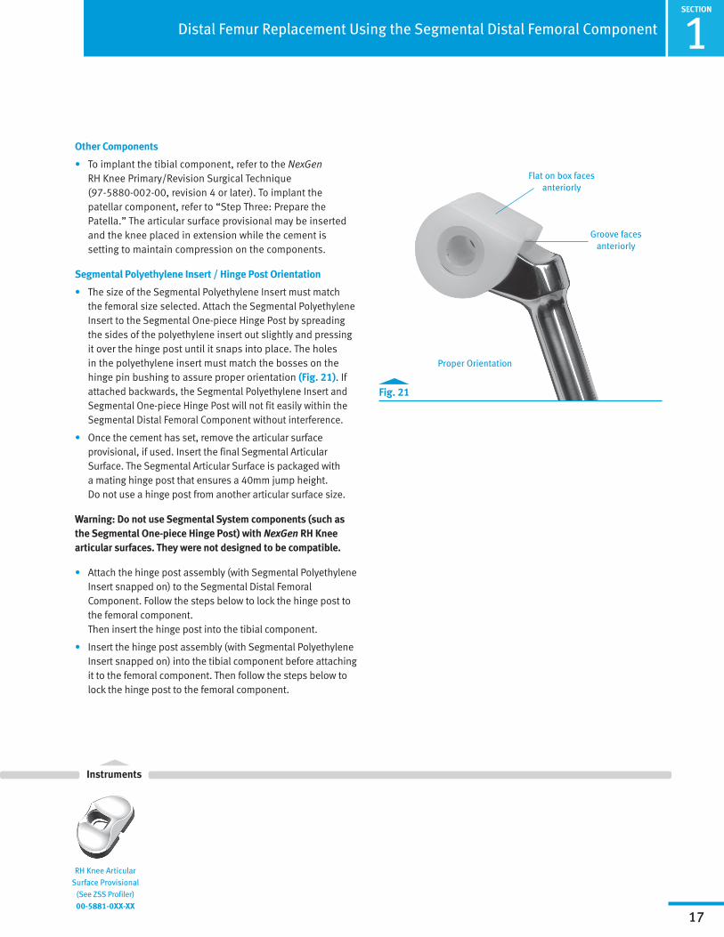
Segmental Polyethylene Insert / Hinge Post Orientation
• The size of the Segmental Polyethylene Insert must match the femoral size selected. Attach the Segmental Polyethylene Insert to the Segmental One-piece Hinge Post by spreading the sides of the polyethylene insert out slightly and pressing it over the hinge post until it snaps into place. The holes in the polyethylene insert must match the bosses on the hinge pin bushing to assure proper orientation (Fig. 21). If attached backwards, the Segmental Polyethylene Insert and Segmental One-piece Hinge Post will not fit easily within the Segmental Distal Femoral Component without interference.
• Once the cement has set, remove the articular surface provisional, if used. Insert the final Segmental Articular Surface. The Segmental Articular Surface is packaged with a mating hinge post that ensures a 40mm jump height. Do not use a hinge post from another articular surface size.
Warning: Do not use Segmental System components (such as the Segmental One-piece Hinge Post) with NexGen RH Knee articular surfaces. They were not designed to be compatible.
• Attach the hinge post assembly (with Segmental Polyethylene Insert snapped on) to the Segmental Distal Femoral Component. Follow the steps below to lock the hinge post to the femoral component. Then insert the hinge post into the tibial component.
• Insert the hinge post assembly (with Segmental Polyethylene Insert snapped on) into the tibial component before attaching it to the femoral component. Then follow the steps below to lock the hinge post to the femoral component.
RH Knee Articular Surface Provisional
(See ZSS Profiler)00-5881-0XX-XX
Proper Orientation
Groove faces anteriorly
Flat on box faces anteriorly

1SECTION
18
Distal Femur Replacement Using the Segmental Distal Femoral Component
Instruments
Implanting the Variable Stiffness Stem/Collar/Segment/ Distal Femoral as Single Unit
• After cementing the collar onto the stem (see previous section “Stem Extension Assembly” for details), insert the construct into the femoral canal and use the Segmental Condyle Impactor (Fig. 22) with the Universal Impactor Handle attached and a mallet to tap the implant until fully seated.
Note: Cement must be added to the base of the Smooth Collar where it contacts bone.
• As the stem advances into the canal, use the vertical mark on the bone to assess the rotational alignment. If the stem fits too tightly in the bone, consider removing the stem and passing the last reamer used through the canal several more times. This can help to increase the hole diameter slightly, which will permit the stem to be more easily impacted into the bone.
Implanting the Variable Stiffness Stem/ Collar Assembly and the Segment/Distal Femur Assembly Separately
• After cementing the collar onto the stem, insert the stem/collar assembly into the femoral canal and use the Segmental Implant/Provisional Male Taper Impactor (assembled to the Universal Impactor Handle) and a mallet to tap the stem implant until fully seated.
Note: Cement must be added to the base of the Smooth Collar where it contacts bone.
• As the stem advances into the canal, use the vertical mark on the bone to assess the rotational alignment. If the stem fits too tightly in the bone, consider removing the stem and passing the last reamer used through the canal several more times. This can help to increase the hole diameter slightly, which will permit the stem to be more easily impacted into the bone.
Note: Remove any debris from tapers prior to assembly of tapered components.
Segmental Implant/Provisional Male Taper Impactor
(Stem Impactor)00-5851-080-00
Segmental Condyle Impactor
00-5851-074-00
Universal Handle6216-01-125
Mallet00-0155-002-00
Fig. 22
Femoral Condyle Impactor

SECTION
1
19
Distal Femur Replacement Using the Segmental Distal Femoral Component
Instruments
Femoral Condyle Impactor
• If using a segment, assemble it to the Distal Femur using the Segmental Condyle Impactor. Impact the assembly together with the Segmental Implant/Provisional Female Taper Impactor assembled to the Universal Impactor Handle. Use a mallet to firmly tap the tapers to the seated position.
• Place the Distal femoral assembly onto the stem taper, and use the Segmental Condyle Impactor (with Universal Handle) and a mallet to tap the two assemblies together until fully seated.
Locking the Hinge Post to the Femoral Component
• Use the Segmental Hinge Pin Aligner to align the hole in the hinge post with the holes of the femoral implant. Then remove the aligner. Use the 4.5mm Hex Driver to insert and thread the Segmental Hinge Pin through the hole of the femoral implant (Fig. 23). Make sure that the pin crosses through the hole in the hinge post bushing. The hinge pin may be inserted either medially or laterally into the femoral component. Use the RH Knee Torque Wrench with the blue handle and 4.5mm Hex Driver to tighten the hinge pin to 130in-lbs. While torquing, watch the stylus on the wrench until it reaches the 130 line, then stop within the patient (Fig. 24). Insert the Segmental Hinge Pin Set Screw on the same side as the hinge pin (Fig. 23) and use the RH Knee Torque Wrench with the blue handle and 4.5mm Hex Driver to torque the set screw to 130in-lbs. While torquing, watch the stylus on the wrench until it reaches the 130 line, then stop within the patient (Fig. 24).
Caution: Do not torque the hinge-pin or set screw beyond 130in-lbs or damage to the hex-drive or driver will occur.
Note: Stretching the knee to insert the hinge post shank into the tibia (back-table hinge post assembly) is not recommended. In vivo assembly of the hinge pin to the hinge post is required with the Segmental Distal Femorals.
Segmental Distal Femoral Component
Segmental Hinge Pin
Segmental Set Screw
Fig. 23
Fig. 24
Segmental Hinge Pin Aligner
00-5851-084-00
Screw Driver (4.5mm)
00-5881-026-00
Torque Wrench 00-5881-027-00
Segmental Implant/Provisional Female
Taper Impactor (Segment Impactor)
00-5851-074-02
Universal Handle6216-01-125
2SECTION
20
Using the Segmental One-piece Hinge Post with the NexGen RH Knee
Instruments
Segmental Set Screw
RH Knee Tibial Polyethylene Bushing
Segmental Polyethylene Insert
Segmental Hinge Pin
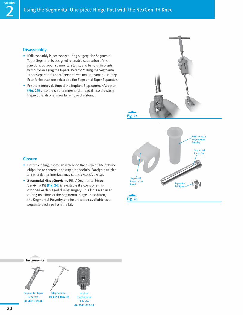
Fig. 26
Fig. 25
Disassembly• If disassembly is necessary during surgery, the Segmental
Taper Separator is designed to enable separation of the junctions between segments, stems, and femoral implants without damaging the tapers. Refer to “Using the Segmental Taper Separator” under “Femoral Version Adjustment” in Step Four for instructions related to the Segmental Taper Separator.
• For stem removal, thread the Implant Slaphammer Adaptor (Fig. 25) onto the slaphammer and thread it into the stem. Impact the slaphammer to remove the stem.
Closure• Before closing, thoroughly cleanse the surgical site of bone
chips, bone cement, and any other debris. Foreign particles at the articular interface may cause excessive wear.
• Segmental Hinge Servicing Kit: A Segmental Hinge Servicing Kit (Fig. 26) is available if a component is dropped or damaged during surgery. This kit is also used during revisions of the Segmental hinge. In addition, the Segmental Polyethylene Insert is also available as a separate package from the kit.
Segmental Taper Separator
00-5851-020-00
Slaphammer00-6551-006-00
Implant Slaphammer
Adapter00-5851-097-11
SECTION
2
21
Using the Segmental One-piece Hinge Post with the NexGen RH Knee
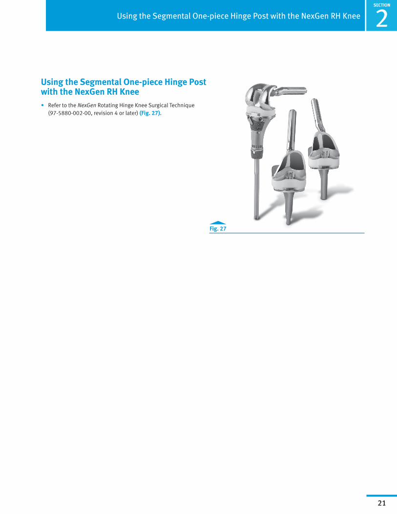
Using the Segmental One-piece Hinge Post with the NexGen RH Knee• Refer to the NexGen Rotating Hinge Knee Surgical Technique
(97-5880-002-00, revision 4 or later) (Fig. 27).
Fig. 27
3SECTION
Total Femoral Replacement
22
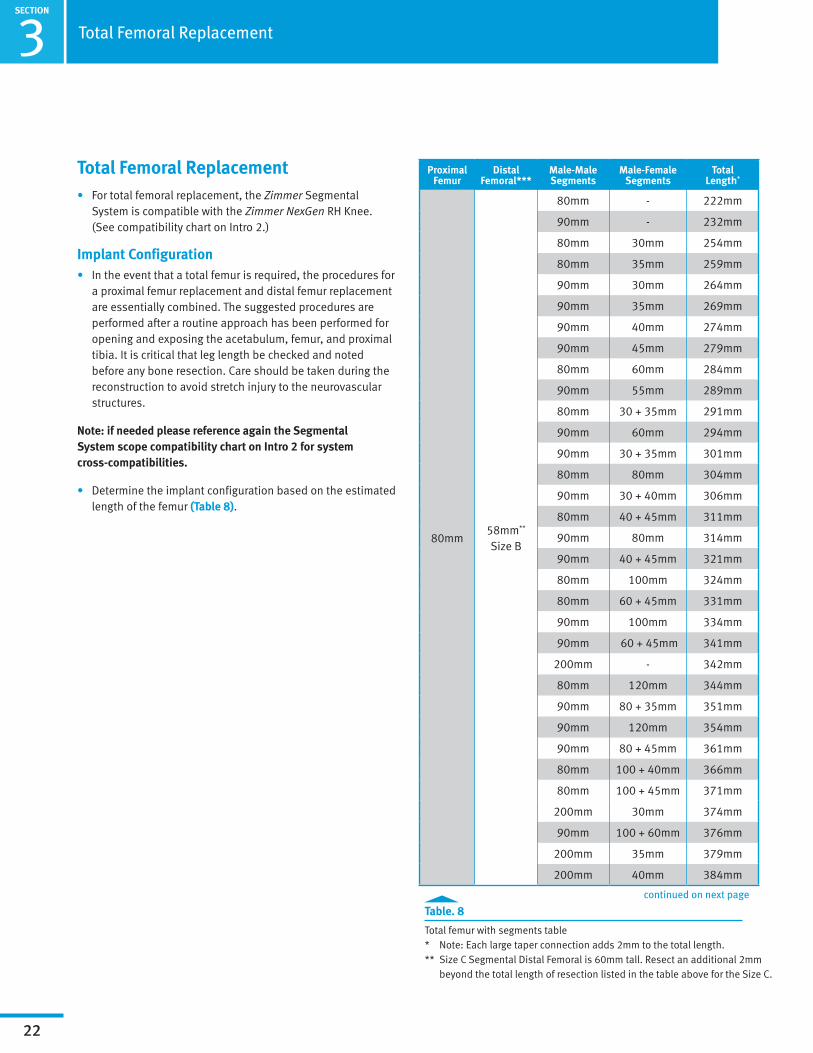
Total Femoral Replacement• For total femoral replacement, the Zimmer Segmental
System is compatible with the Zimmer NexGen RH Knee. (See compatibility chart on Intro 2.)
Implant Configuration• In the event that a total femur is required, the procedures for
a proximal femur replacement and distal femur replacement are essentially combined. The suggested procedures are performed after a routine approach has been performed for opening and exposing the acetabulum, femur, and proximal tibia. It is critical that leg length be checked and noted before any bone resection. Care should be taken during the reconstruction to avoid stretch injury to the neurovascular structures.
Note: if needed please reference again the Segmental System scope compatibility chart on Intro 2 for system cross-compatibilities.
• Determine the implant configuration based on the estimated length of the femur (Table 8).
Table. 8
Total femur with segments table* Note: Each large taper connection adds 2mm to the total length.** Size C Segmental Distal Femoral is 60mm tall. Resect an additional 2mm
beyond the total length of resection listed in the table above for the Size C.
Proximal Femur
Distal Femoral***
Male-Male Segments
Male-Female Segments
Total Length*
80mm58mm**
Size B
80mm - 222mm
90mm - 232mm
80mm 30mm 254mm
80mm 35mm 259mm
90mm 30mm 264mm
90mm 35mm 269mm
90mm 40mm 274mm
90mm 45mm 279mm
80mm 60mm 284mm
90mm 55mm 289mm
80mm 30 + 35mm 291mm
90mm 60mm 294mm
90mm 30 + 35mm 301mm
80mm 80mm 304mm
90mm 30 + 40mm 306mm
80mm 40 + 45mm 311mm
90mm 80mm 314mm
90mm 40 + 45mm 321mm
80mm 100mm 324mm
80mm 60 + 45mm 331mm
90mm 100mm 334mm
90mm 60 + 45mm 341mm
200mm - 342mm
80mm 120mm 344mm
90mm 80 + 35mm 351mm
90mm 120mm 354mm
90mm 80 + 45mm 361mm
80mm 100 + 40mm 366mm
80mm 100 + 45mm 371mm
200mm 30mm 374mm
90mm 100 + 60mm 376mm
200mm 35mm 379mm
200mm 40mm 384mm
continued on next page

SECTION
3Total Femoral Replacement
23
Proximal Femur
Distal Femoral
Male-Male Segments
Male-Female Segments
Total Length*
80mm58mm**
Size B
200mm 45mm 389mm
90mm 100 + 60mm 396mm
80mm 140 + 35mm 401mm
200mm 60mm 404mm
80mm 140 + 45mm 411mm
90mm 180mm 414mm
90mm 140 + 45mm 421mm
200mm 80mm 424mm
200mm 40 + 45mm 431mm
90mm 200mm 434mm
90mm 160 + 45mm 441mm
200mm 100mm 446mm
200mm 60 + 45mm 451mm
90mm 220mm 454mm
90mm 180 + 45mm 461mm
200mm 120mm 464mm
200mm 80 + 45mm 471mm
90mm 200 + 40mm 476mm
90mm 200 + 45mm 481mm
200mm 140mm 484mm
200mm 100 + 45mm 491mm
90mm 200 + 60mm 496mm
90mm 220 + 45mm 501mm
200mm 160mm 504mm
200mm 120 + 45mm 511mm
90mm 220 + 60mm 516mm
200mm 140 + 35mm 521mm
200mm 180mm 524mm
Table. 8
Total femur with segments table* Note: Each large taper connection adds 2mm to the total length.** Size C Segmental Distal Femoral is 60mm tall. Resect an additional 2mm
beyond the total length of resection listed in the table above for the Size C.
continued from previous page

3SECTION
Total Femoral Replacement
24
Proximal Femoral Options• The Zimmer Segmental System offers three solutions for
proximal femoral replacement (Fig. 28) with various tissue attachment options (Fig. 29a, 29b & 29c), including Tissue Attachment Washers for the Trabecular Metal Material components.
• The standard Proximal Femoral component has suture holes on both the medial and lateral aspects of the prosthesis.
• The Trabecular Metal Proximal Femoral component offers solutions for attaching both trochanteric bone and/or soft tissue to the prosthesis. Multiple Tissue Attachment Washer options are available depending on the type and thickness of remaining tissue. Soft tissue may also be attached to the prosthesis via suture holes on both medial and lateral sides.
• The Zimmer Segmental System Proximal Femoral components are compatible with all Zimmer Segmental System segments. The Segmental Proximal Femoral components can be anteverted in 20-degree increments to enhance proximal joint stability using the anteversion alignment features between the either the Proximal Femoral component or the Distal Femoral component and the Segmental Femoral/Tibial Segments (Refer to the Zimmer Segmental Proximal Femoral Components and Intercalary Segments Surgical Technique 97-5850-007-00 for instructions and compatibility).
Distal Femoral Replacement• To replace the distal femur, begin with Step 4: Assembly
Provisional Components and Perform Trial Reduction on page 6 of this surgical technique.
Fig. 28
Fig. 29b
Fig. 29c
Fig. 29a
SECTION
3Total Femoral Replacement
25
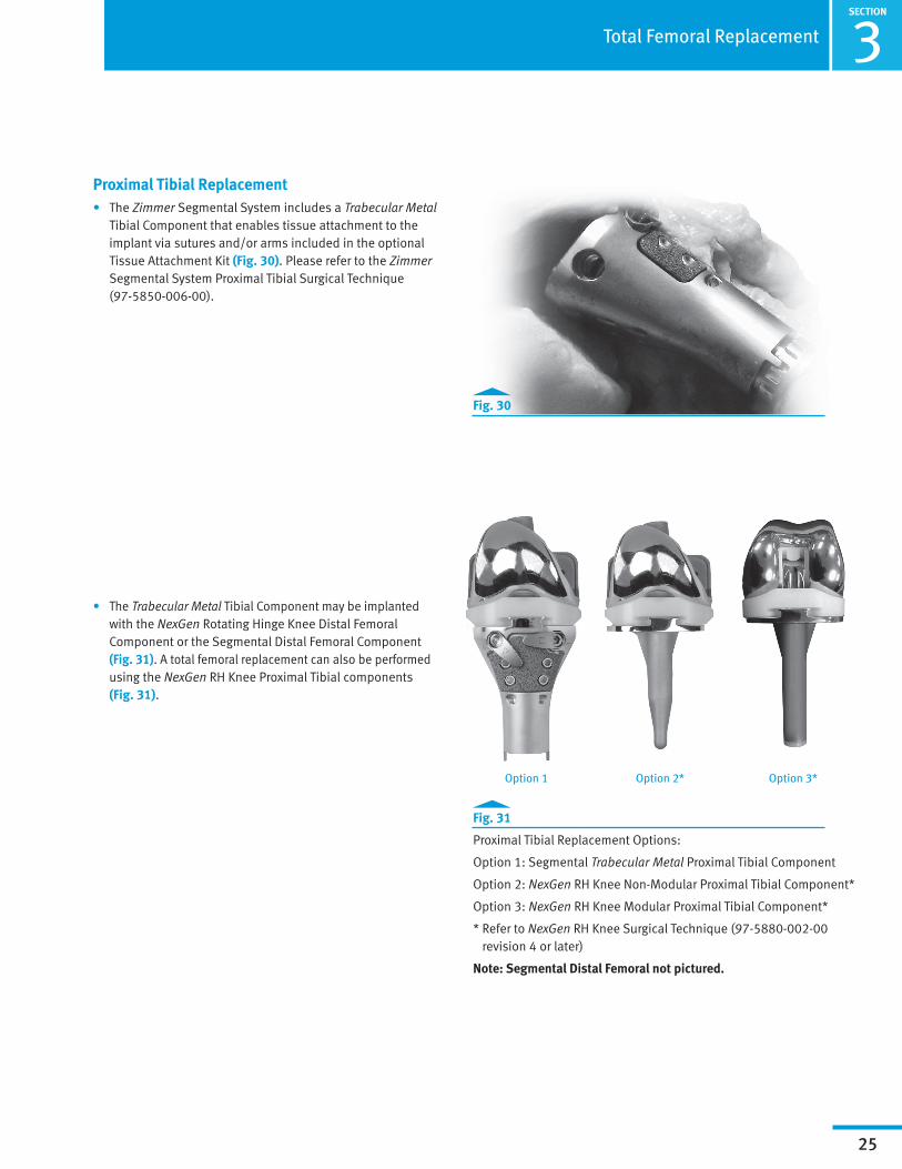
Proximal Tibial Replacement• The Zimmer Segmental System includes a Trabecular Metal
Tibial Component that enables tissue attachment to the implant via sutures and/or arms included in the optional Tissue Attachment Kit (Fig. 30). Please refer to the Zimmer Segmental System Proximal Tibial Surgical Technique (97-5850-006-00).
• The Trabecular Metal Tibial Component may be implanted with the NexGen Rotating Hinge Knee Distal Femoral Component or the Segmental Distal Femoral Component (Fig. 31). A total femoral replacement can also be performed using the NexGen RH Knee Proximal Tibial components (Fig. 31).
Fig. 30
Fig. 31
Proximal Tibial Replacement Options:
Option 1: Segmental Trabecular Metal Proximal Tibial Component
Option 2: NexGen RH Knee Non-Modular Proximal Tibial Component*
Option 3: NexGen RH Knee Modular Proximal Tibial Component*
* Refer to NexGen RH Knee Surgical Technique (97-5880-002-00 revision 4 or later)
Note: Segmental Distal Femoral not pictured.
Option 1 Option 2* Option 3*
ASECTION
26
Appendix A: NexGen RH Knee & Segmental Articular Surface/Hinge Kit Compatibilities
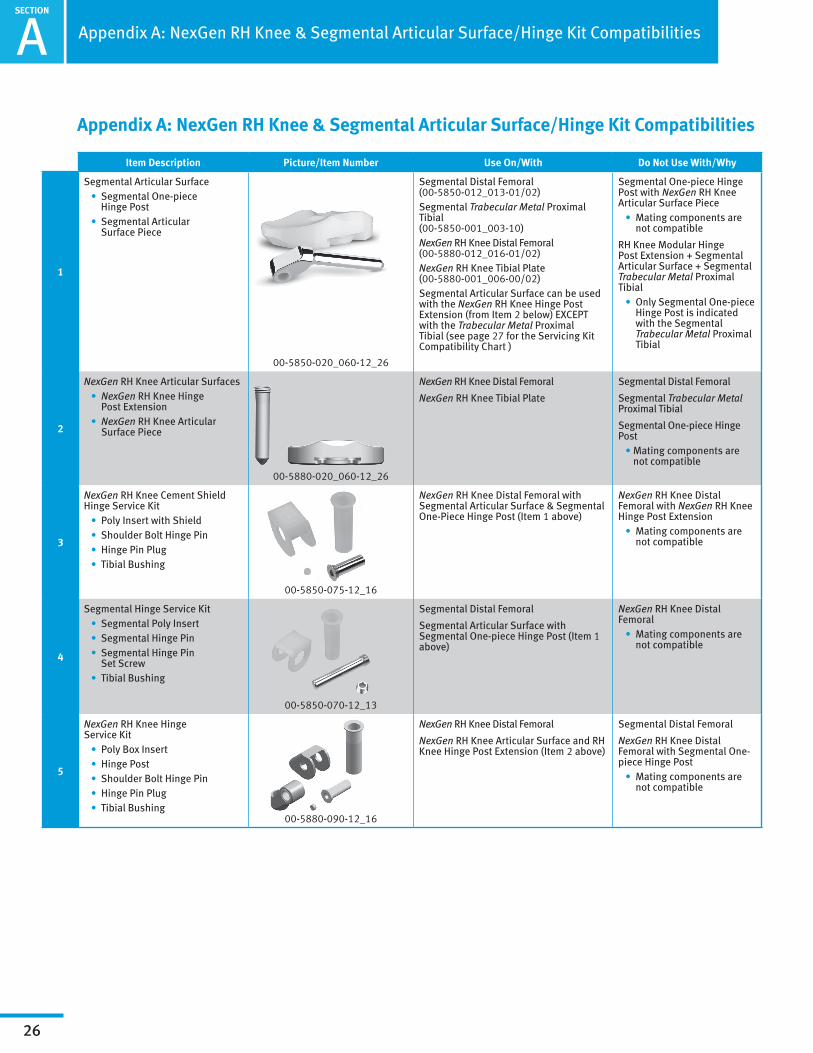
Appendix A: NexGen RH Knee & Segmental Articular Surface/Hinge Kit Compatibilities
Item Description Picture/Item Number Use On/With Do Not Use With/Why
1
Segmental Articular Surface • Segmental One-piece
Hinge Post • Segmental Articular
Surface Piece
00-5850-020_060-12_26
Segmental Distal Femoral (00-5850-012_013-01/02) Segmental Trabecular Metal Proximal Tibial (00-5850-001_003-10) NexGen RH Knee Distal Femoral (00-5880-012_016-01/02) NexGen RH Knee Tibial Plate (00-5880-001_006-00/02)Segmental Articular Surface can be used with the NexGen RH Knee Hinge Post Extension (from Item 2 below) EXCEPT with the Trabecular Metal Proximal Tibial (see page 27 for the Servicing Kit Compatibility Chart )
Segmental One-piece Hinge Post with NexGen RH Knee Articular Surface Piece • Mating components are
not compatible
RH Knee Modular Hinge Post Extension + Segmental Articular Surface + Segmental Trabecular Metal Proximal Tibial • Only Segmental One-piece
Hinge Post is indicated with the Segmental Trabecular Metal Proximal Tibial
2
NexGen RH Knee Articular Surfaces • NexGen RH Knee Hinge
Post Extension • NexGen RH Knee Articular
Surface Piece
00-5880-020_060-12_26
NexGen RH Knee Distal Femoral
NexGen RH Knee Tibial Plate
Segmental Distal Femoral
Segmental Trabecular Metal Proximal Tibial
Segmental One-piece Hinge Post • Mating components are
not compatible
3
NexGen RH Knee Cement Shield Hinge Service Kit • Poly Insert with Shield • Shoulder Bolt Hinge Pin • Hinge Pin Plug • Tibial Bushing
00-5850-075-12_16
NexGen RH Knee Distal Femoral with Segmental Articular Surface & Segmental One-Piece Hinge Post (Item 1 above)
NexGen RH Knee Distal Femoral with NexGen RH Knee Hinge Post Extension • Mating components are
not compatible
4
Segmental Hinge Service Kit • Segmental Poly Insert • Segmental Hinge Pin • Segmental Hinge Pin
Set Screw • Tibial Bushing
00-5850-070-12_13
Segmental Distal Femoral
Segmental Articular Surface with Segmental One-piece Hinge Post (Item 1 above)
NexGen RH Knee Distal Femoral • Mating components are
not compatible
5
NexGen RH Knee Hinge Service Kit • Poly Box Insert • Hinge Post • Shoulder Bolt Hinge Pin • Hinge Pin Plug • Tibial Bushing
00-5880-090-12_16
NexGen RH Knee Distal Femoral
NexGen RH Knee Articular Surface and RH Knee Hinge Post Extension (Item 2 above)
Segmental Distal Femoral
NexGen RH Knee Distal Femoral with Segmental One-piece Hinge Post • Mating components are
not compatible

SECTION
A
27
Appendix A: NexGen RH Knee & Segmental Articular Surface/Hinge Kit Compatibilities
Servicing Kit Compatibility Chart
RH Knee Hinge Servicing Kit Used Compatible Articular Surfaces and Hinge Components
Base Component SystemNexGen RH Knee Hinge
Servicing Kit
NexGen RH Knee Articular Surface (with the Hinge
Post Extension)
Segmental Articular Surface with the Segmental
One-Piece Hinge Post
NexGen RH Knee Articular Surface (with the Hinge
Post Extension)
Base Component SystemNexGen RH Knee Cement
Shield Servicing Kit
Segmental Articular Surface with the Segmental
One-Piece Hinge Post
DISCARDDISCARD
OR
Segmental Articular Surface (with the Hinge Post)
A
SECTION
28
B
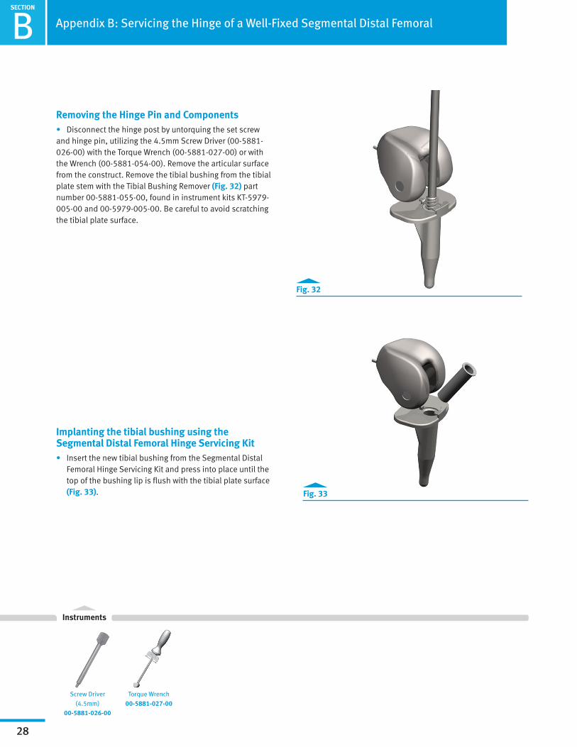
Removing the Hinge Pin and Components• Disconnect the hinge post by untorquing the set screw and hinge pin, utilizing the 4.5mm Screw Driver (00-5881-026-00) with the Torque Wrench (00-5881-027-00) or with the Wrench (00-5881-054-00). Remove the articular surface from the construct. Remove the tibial bushing from the tibial plate stem with the Tibial Bushing Remover (Fig. 32) part number 00-5881-055-00, found in instrument kits KT-5979-005-00 and 00-5979-005-00. Be careful to avoid scratching the tibial plate surface.
Implanting the tibial bushing using the Segmental Distal Femoral Hinge Servicing Kit • Insert the new tibial bushing from the Segmental Distal
Femoral Hinge Servicing Kit and press into place until the top of the bushing lip is flush with the tibial plate surface (Fig. 33).
Fig. 32
Fig. 33
Screw Driver (4.5mm)
00-5881-026-00
Torque Wrench 00-5881-027-00
Instruments
Appendix B: Servicing the Hinge of a Well-Fixed Segmental Distal Femoral


Contact your Zimmer representative or visit us at www.zimmer.com
Disclaimer
This documentation is intended exclusively for physicians and is not intended for laypersons.Information on the products and procedures contained in this document is of a general nature and does not represent and does not constitute medical advice or recommendations. Because this information does not purport to constitute any diagnostic or therapeutic statement with regard to any individual medical case, each patient must be examined and advised individually, and this document does not replace the need for such examination and/or advice in whole or in part.
Please refer to the package inserts for important product information, including, but not limited to, contraindications, warnings, precautions, and adverse effects.
97-5850-004-00 Rev. 2 3-17-14 Printed in USA ©2014 Zimmer, Inc.