zimmer natural nail system · 8 | zimmer natural nail – cephalomedullary small nail surgical...
TRANSCRIPT
Zimmer® Natural Nail® SystemCephalomedullary Small Nail
Surgical Technique

Table of Contents
Product Overview ..................................................................................................... 2
Implant Overview ..................................................................................................... 2
Indications ................................................................................................................ 3
Contraindications ..................................................................................................... 3
Surgical Technique ................................................................................................... 4
Preoperative Planning ........................................................................................ 4
Patient Positioning .............................................................................................. 4
Reduction ........................................................................................................... 4
Starting Point Location ....................................................................................... 5
Proximal Reaming ............................................................................................... 8
Shaft Reaming .................................................................................................. 10
Implant Selection .............................................................................................. 10
Nail Assembly and Insertion ............................................................................. 10
Lag Screw Placement ........................................................................................ 13
Distal Targeting For Short Nails ......................................................................... 22
Freehand Technique for Long Nails ................................................................... 24
Final Implant Placement .................................................................................... 25
Postoperative Care ........................................................................................... 26
Nail Extraction .................................................................................................. 26
Cephalomedullary Long Nail Details ...................................................................... 28
Cephalomedullary Short Nail Details ..................................................................... 29
Product Information ............................................................................................... 30
2 | Zimmer Natural Nail – Cephalomedullary Small Nail Surgical Technique 3 | Zimmer Natural Nail – Cephalomedullary Small Nail Surgical Technique
Product OverviewThe Zimmer Natural Nail System is a system of intramedullary nails, screws, instruments and other associated implants that are designed to provide stable internal fixation for fractured long bones. The nails have been designed for specific applications to help restore the shape of the fractured bone to its natural, pre-injured state.
The Cephalomedullary Nail is designed to treat fractures of the femur, especially intertrochanteric and subtrochanteric fractures. The nail features a small proximal section that is designed to minimize the amount of bone that must be removed for nail insertion. A lag screw is placed through the nail into the femoral head to secure the nail in place proximally and help control the different segments of the bone while healing occurs. Screws are placed through the nail distally to further secure the implant in place and maintain length and alignment while healing occurs.
A choice of short and long nails as well as nails of different diameters and center-column-diaphyseal (CCD) angles are available to best match the individual anatomy of the patient.
Implant OverviewNail Diameters: 10 mm, 11.5 mm, 13 mm, 14.5 mm (14.5 mm is available only for short nails)
Nail Lengths: Small: 21.5 cm Long: 30 to 46 cm
CCD Angles: 125°, 130°, 135° (CCD 135° is only available for short nails with diameter 10, 11.5 and 13 mm)
Lag Screw Diameter: 10.5 mm
Lag Screw Lengths: 70 to 130 mm in 5 mm increments
Distal Screw Diameter: 5.0 mm
Distal Screw Lengths: 20 to 60 mm in 2.5 mm increments 65 to 100 mm in 5 mm increments
Distal screws available in fully- and partially-threaded configurations
Materials: Ti-6Al-4V alloy
Precision instrumentation is provided to help implant the nail. Many of the instruments and implants feature a color coding system to help the surgical team use the system. Certain instruments are not color coded. The color coding system is referenced in the technique. A wall chart (97-2493-003-00) is also available to help explain the color coding system.
IndicationsThe Zimmer Natural Nail System is intended for temporary fracture fixation and stabilization of the bone.
Indications for the Cephalomedullary nails include:
• Compound and simple shaft fractures
• Proximal, metaphyseal and distal shaft fractures
• Segmental fractures
• Comminuted fractures
• Fractures involving osteopenic and osteoporotic bone
• Pathological fractures
• Fractures with bone loss
• Pseudoarthrosis, non-union, malunion and delayed union
• Periprosthetic fractures
• Surgically created defects such as osteotomies
• Intertrochanteric and subtrochanteric fractures
Contraindications• A medullary canal obliterated by a previous
fracture or tumor
• Bone shaft having excessive bow or deformity
• Lack of bone substance or bone quality, which makes stable seating of the implant impossible
• All concomitant diseases that can impair the functioning and the success of the implant
• Infection
• Insufficient blood circulation
• Skeletally immature patients
Warning: This nail should only be used to treat a periprosthetic fracture if the in situ device is firmly fixed. When treating a periprosthetic fracture, the nail should be positioned so that it does not come in contact with the in situ device.
4 | Zimmer Natural Nail – Cephalomedullary Small Nail Surgical Technique 5 | Zimmer Natural Nail – Cephalomedullary Small Nail Surgical Technique
Preoperative PlanningPreoperative planning is recommended before begin-ning the surgical procedure. An A/P and Lateral x-ray of the injured femur should be taken preoperatively and evaluated for length, canal size and implant suitability. A/P and Lateral x-rays of the contralateral uninjured femur can also be taken preoperatively to provide insight into the characteristics of the pre-injured femur.
Patient PositioningPatients can be positioned either supine or in a lateral decubitus position. As the C-arm will be used during the procedure, care should be taken to orient the patient to allow for A/P and Lateral imaging of the proximal femur, the fracture and the distal femur. The use of a fracture table can be beneficial in helping to reduce fractures as well as to facilitate intraoperative imaging with a C-arm. The patient should be positioned to allow for easy access to the greater trochanter of the femur with instrumentation. Adduction of the affected leg can also be helpful, especially in the supine position.
Drape the patient appropriately to allow the surgeon to work around the hip and full length of the femur (to the knee).
ReductionIt is critical to achieve anatomic reduction before beginning any of the steps to place the intramedullary nail. Traction should be used as necessary to help achieve fracture reduction. Several instruments are available to assist in fracture reduction including clamps, ball spike pushers and Steinmann pins.
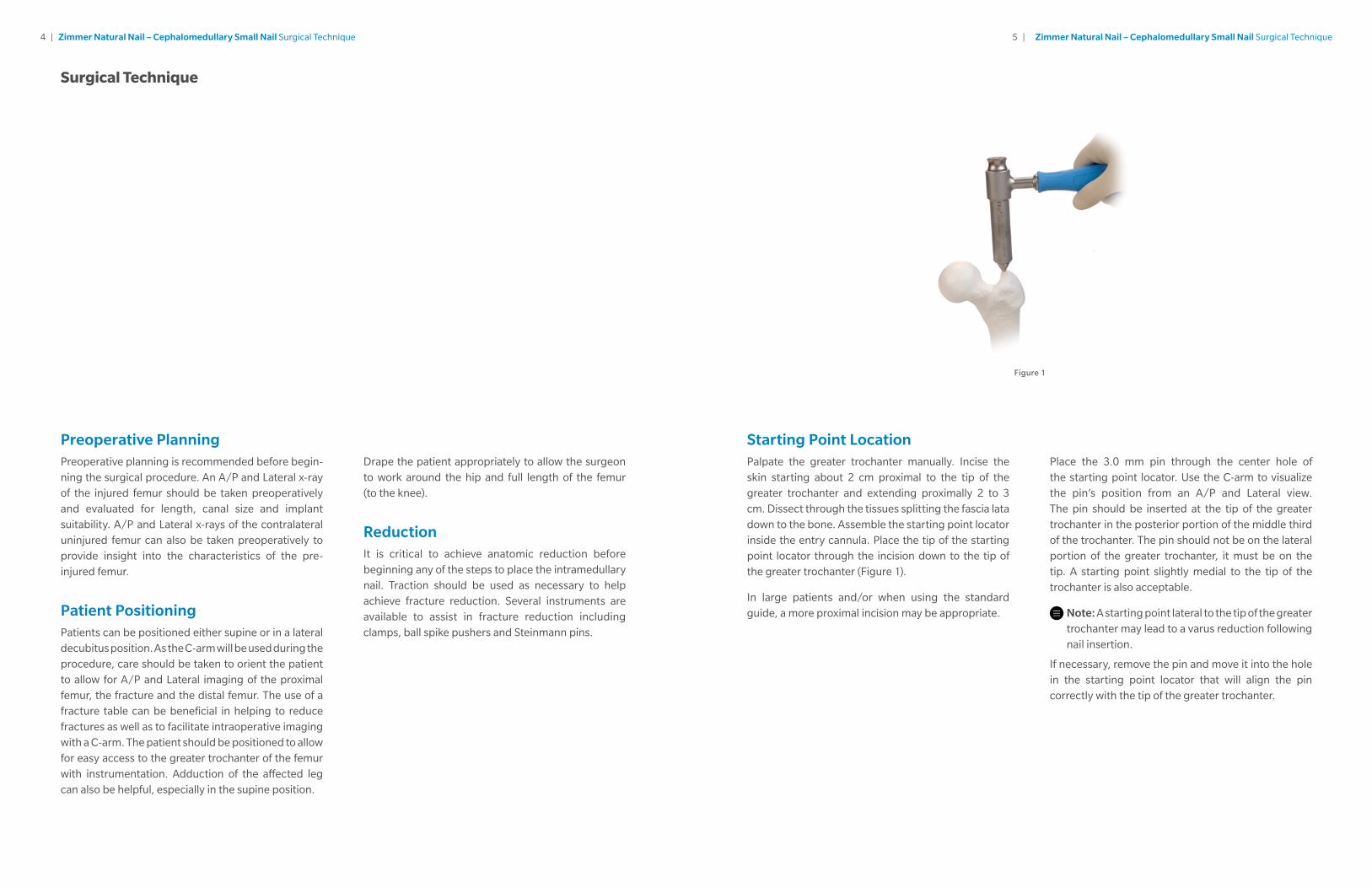
Starting Point LocationPalpate the greater trochanter manually. Incise the skin starting about 2 cm proximal to the tip of the greater trochanter and extending proximally 2 to 3 cm. Dissect through the tissues splitting the fascia lata down to the bone. Assemble the starting point locator inside the entry cannula. Place the tip of the starting point locator through the incision down to the tip of the greater trochanter (Figure 1).
In large patients and/or when using the standard guide, a more proximal incision may be appropriate.
Place the 3.0 mm pin through the center hole of the starting point locator. Use the C-arm to visualize the pin’s position from an A/P and Lateral view. The pin should be inserted at the tip of the greater trochanter in the posterior portion of the middle third of the trochanter. The pin should not be on the lateral portion of the greater trochanter, it must be on the tip. A starting point slightly medial to the tip of the trochanter is also acceptable.
Note: A starting point lateral to the tip of the great er trochanter may lead to a varus reduction following nail insertion.
If necessary, remove the pin and move it into the hole in the starting point locator that will align the pin correctly with the tip of the greater trochanter.
Surgical Technique
Figure 1
6 | Zimmer Natural Nail – Cephalomedullary Small Nail Surgical Technique 7 | Zimmer Natural Nail – Cephalomedullary Small Nail Surgical Technique
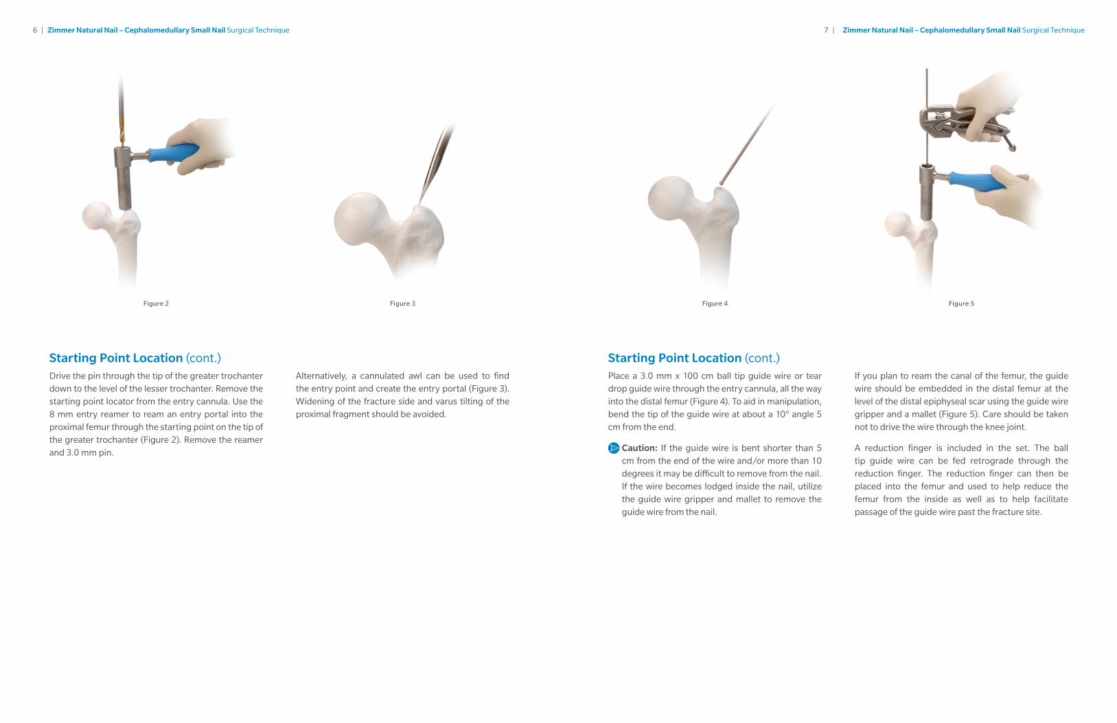
Starting Point Location (cont.)Drive the pin through the tip of the greater trochanter down to the level of the lesser trochanter. Remove the starting point locator from the entry cannula. Use the 8 mm entry reamer to ream an entry portal into the proximal femur through the starting point on the tip of the greater trochanter (Figure 2). Remove the reamer and 3.0 mm pin.
Alternatively, a cannulated awl can be used to find the entry point and create the entry portal (Figure 3). Widening of the fracture side and varus tilting of the proximal fragment should be avoided.
Figure 2 Figure 4Figure 3 Figure 5
Starting Point Location (cont.)Place a 3.0 mm x 100 cm ball tip guide wire or tear drop guide wire through the entry cannula, all the way into the distal femur (Figure 4). To aid in manipulation, bend the tip of the guide wire at about a 10° angle 5 cm from the end.
Caution: If the guide wire is bent shorter than 5 cm from the end of the wire and/or more than 10 degrees it may be difficult to remove from the nail. If the wire becomes lodged inside the nail, utilize the guide wire gripper and mallet to remove the guide wire from the nail.
If you plan to ream the canal of the femur, the guide wire should be embedded in the distal femur at the level of the distal epiphyseal scar using the guide wire gripper and a mallet (Figure 5). Care should be taken not to drive the wire through the knee joint.
A reduction finger is included in the set. The ball tip guide wire can be fed retrograde through the reduction finger. The reduction finger can then be placed into the femur and used to help reduce the femur from the inside as well as to help facilitate passage of the guide wire past the fracture site.
8 | Zimmer Natural Nail – Cephalomedullary Small Nail Surgical Technique 9 | Zimmer Natural Nail – Cephalomedullary Small Nail Surgical Technique
Starting Point Location (cont.)If a long nail is to be implanted, assemble the two piece nail length gauge. This step can be skipped if using a short nail (21.5 cm in length). Slide the tube portion of the gauge over the 3.0 mm x 100 cm guide wire until the tip of the tube is at the level of the tip of the greater trochanter (confirm position using fluoroscopy) (Figure 6). The proximal end of the guide wire indicates the length of the wire in the canal. When determining nail length, consideration should be taken as to how deep the nail will be inserted into the femur based upon the shape of the patient’s proximal femur. A ruler is also included in the set which can be used to radiographically determine nail length.
Proximal ReamingUse the 15.5 mm tapered reamer (blue) to prepare the proximal femur for the proximal portion of the nail (Figure 7). The C-arm should be used to visualize the depth of the reamer in the proximal femur. Care should be taken to keep the reamer in line with the shaft of the femur to avoid reaming through the cortex of the femur.
The 15.5 mm tapered reamer has three grooves on it. The most proximal groove indicates the final position of the top of the nail. The two distal grooves help visualize the placement of the lag screw. Visualizing a line between these grooves on each side of the reamer (under fluoroscopic visualization) will indicate where a 130° CCD angle lag screw would be placed in the femoral neck and head.
Figure 6 Figure 7 Figure 8 Figure 9 Figure 10
Proximal Reaming (cont.)A channel reamer is also available for proximal reaming. The inner channel reamer is placed inside the 14.5 mm channel reamer sleeve and secured by twisting the connector. The channel reamer is then advanced over the guide wire through the greater trochanter. Advance the reamer to the level of the lesser trochanter (Figure 8), or deep enough to accommodate the proximal body of the nail.
After reaming to the proper depth, the inner channel reamer is removed by disengaging the connector and pulling the inner channel reamer out of the surgical field (Figure 9). The channel reamer sleeve can be left in place to act as a tissue protection sleeve during shaft reaming for shaft reamers up to 13 mm in diameter. To achieve greater reaming depth or diameter, the entry cannula can be used in place of the sleeve. To facilitate reamer removal via the sleeve, power the reamer until it enters the sleeve. Following shaft reaming the channel reamer sleeve should be removed from the surgical field (Figure 10).
10 | Zimmer Natural Nail – Cephalomedullary Small Nail Surgical Technique 11 | Zimmer Natural Nail – Cephalomedullary Small Nail Surgical Technique
Shaft ReamingReaming should be performed through the entry cannula. To reduce the risk of enlarging the entry hole laterally, push the entry cannula medially. Start with a small reamer. Increase the diameter of the reamer by 0.5 - 1.0 mm depending on the amount of resistance felt while reaming (Figure 11). When cortical chatter occurs, stop reaming. Choose a nail that is 1.5 - 2.0 mm smaller than the last reamer used. If a short nail is to be used, it is only necessary to ream the proximal 21.5 cm of the canal. If a long nail is planned, ream the full length of the canal. The guide wire pusher can help prevent the guide wire from coming out of the femur during reaming.
Note: If the guide wire becomes lodged within the reamer, use the guide wire pusher to push the guide wire back into the intramedullary canal.
Nail Assembly and Insertion (cont.)Begin threading the connecting bolt (by using the connecting bolt inserter) into the proximal portion of the nail. Orient the proximal portion of the nail so that the slots in the nail match up with the corresponding tines on the barrel of the targeting guide. Completely tighten the connecting bolt using the connection bolt inserter together with the wrench to secure the nail to the guide (Figure 13).
Lay the guide attached to the nail over the femur. Confirm that the bow of the nail is anterior similar to the bow of the femur. Confirm also that the lag screw hole in the nail is oriented to guide a lag screw into the femoral head. Care must be taken to ensure that the correct nail is selected and that it is assembled correctly to the guide. If this is not the case, loosen and reattach the nail appropriately or choose the correct nail and attach it to the guide.
Implant SelectionThe diameter and length of the nail have already been determined (using nail length gauge and last size of reamer utilized). Visualizing the reduced femur and/or the contralateral femur, determine which CCD angle is appropriate for the patient.
Nail Assembly and InsertionThe color code for the Cephalomedullary Nail is blue. Ti-6Al-4V alloy nails, the targeting guide small and the connecting bolt all have blue colors on them, as well as the word BLUE on them. The arrow on the nail (with an R for a right nail or an L for a left nail) will line up with the arrow on the barrel of the guide when the nail is correctly aligned. Place the connecting bolt through the barrel of the targeting guide (Figure 12).
Figure 11 Figure 13Figure 12
Note: Use a lag screw cannula and the lag screw reamer or a cannula, drill sleeve and drill to verify that the guide will target all required holes in the nail correctly. Hole indicators can be placed in static (ST) and dynamic (DY) holes of the targeting guide and in holes for CCD angles that will not be used to avoid the accidental use of those holes during the surgery. Use a pushand-twist motion when inserting the hole indicators to help ensure that they stay in place.
Note: The small targeting guide is designed to target the transverse distal static (ST) and dynamic (DY) holes in short nails. As the guide is designed to work with both left and right ST and DY holes, care must be taken to ensure that the correct ST/DY holes will be used for the surgery (use the left holes when using a left nail, and vice versa). The holes that will be used to place screws into the distal portion of short nails are on the anterior side of the guide when the patient is in a supine position.
12 | Zimmer Natural Nail – Cephalomedullary Small Nail Surgical Technique 13 | Zimmer Natural Nail – Cephalomedullary Small Nail Surgical Technique
Nail Assembly and Insertion (cont.)Insert the nail over the guide wire with the arm of the guide facing anteriorly (Figure 14).
As the nail passes through the canal, it will naturally turn approximately 90° until the anterior bow of the nail is in line with the bow of the femur. Monitor the progression of the nail down the canal using the C-arm, especially as the nail is passing through or near the fracture site.
Caution: Do not pry excessively on the targeting guide as damage may result.
If the nail does not pass down the canal easily, attach the impaction head to the targeting guide. Using the mallet, impact gently on the impaction head (Figure 15).
Caution: Do not strike excessively as damage to the guide and bone may result. Verify that the connecting bolt is tight while, and after, impacting. Do not impact on any portion of the targeting guide as this may break the guide or cause it to lose its accuracy.
Figure 14 Figure 15
If the nail will not advance with impaction, remove the nail and ream the canal to a larger diameter at additional 0.5 mm increments or consider using a smaller diameter nail.
Anteversion can be verified by placing a threaded guide pin through the skin and soft tissue along the anterior axis of the femoral neck.
Remove the guide wire from the nail using the guide wire gripper.
If it is desired to utilize an antirotation pin to assist in stabilizing the femoral head during lag screw preparation and insertion, a 3.0 mm pin can be placed into the femoral neck and head using the double barrel cannula that targets both the lag screw and anti rotation 3.0 mm pin.
Lag Screw PlacementFor the small targeting guide, instruments marked pink are utilized to place the lag screw. Marks on the targeting guides near the holes indicate the color of cannula that should be passed through that specific hole. The chart above details the color coded instruments that are used to target and place the lag screw.
Caution: Retighten the connecting bolt to the nail to maintain targeting accuracy.
The Tip-Apex Distance (TAD), the sum of the distances of the tip of the lag screw to the apex of the femoral head in the A/P and Lateral x-ray views, has been shown to be a key indicator in reducing cut-out of lag screws in the femoral head. The TAD should be less than 25 mm.1
Position the targeting guide so that the trajectory of the lag screw cannula will place the lag screw in the appropriate position in the femoral head and neck. Pins can be held over the skin in line with the lag screw cannula to help estimate this position and correct CCD angle.
Note: If planning to use an antirotation pin to further stabilize the femoral head, insert the double cannula instead of the lag screw cannula.
Assemble the lag screw trocar into the lag screw cannula and pass through the correct hole in the targeting guide for the chosen CCD angle. The lag screw hole labeled 125 is designed to be used with the long and short nails containing a 125° CCD angle, the lag screw hole labeled 130 is designed to be used with the long and short nails containing a 130° CCD angle, and the lag screw hole labeled 135 is designed to be used with the short nails containing a 135° CCD angle.
Instrument Type Small
4.3 mm Drill Sleeve Pink
4.3 mm Drill Pink-Red
Lag Screw Cannula Pink
3.2 mm Lag Screw Pin Sleeve Pink
Lag Screw Reamer Pink
Lag Screw Tap Pink
Lag Screw Inserter Pink
Lag Screw Retaining Shaft Pink
14 | Zimmer Natural Nail – Cephalomedullary Small Nail Surgical Technique 15 | Zimmer Natural Nail – Cephalomedullary Small Nail Surgical Technique
Lag Screw Placement (cont.)Make a small skin incision, then dissect through the fascia and other soft tissues down to the bone. Advance the cannula through the guide down to the bone (Figure 16).
Caution: Do not impact on the cannula, as the tip of the cannula may skive along the bone and prevent accurate targeting.
Another A/P C-arm image can be taken at this point to ensure that the targeting guide is still aligned correctly by visualizing a line extending from the center of the cannula into the femoral head. Remove the trocar and insert the 3.2 mm lag screw pin sleeve. Insert a 3.2 mm pin through the pin sleeve. Under fluoroscopy, drill the 3.2 mm pin to the level of the subchondral bone of the femoral head without penetrating the femoral cortex (Figure 17).
Lag Screw Placement (cont.)If it is desired to utilize an antirotation pin to assist in stabilizing the femoral head during lag screw insertion, a 3.0 mm antirotation pin can be placed into the femoral neck and head using a double cannula. Use the smaller sleeve of the double cannula to place this pin at this time. The pin is passed so that it does not penetrate the femoral cortex in the femoral head or neck (Figure 18). Place pin to appropriate depth beyond the fracture site to provide stabilization.
Note: Place the 3.2 mm pin prior to the antirotation pin to reduce mistargeting. Position the antirotation pin slightly proximal to the center-line of the femoral neck.
Assess the position of the pin using the C-arm in the A/P and Lateral planes. If the pin is appropriately placed, proceed with the next steps.
Note: If the pin is not appropriately placed, remove it, adjust the guide under fluoroscopy and replace the pin correctly.
Technique Tip: If the pin appears to be changing direction at the point it enters the lateral cortex of the femur, remove the pin and pin sleeve and perforate the lateral cortex using the specific 4.3 mm drill bit with the corresponding drill sleeve. Replace the pin sleeve in the cannula and drive the pin as previously stated to the level of the subchondral bone in the femoral head.
Alternatively, the pin can be placed using a freehand technique anterior to the nail and into the femoral neck and head.2,3
Note: Insert 3.2 mm pin anterior to the nail. In-serting them posterior to the nail may cause damage to the neurovascular structures.
Remove the 3.2 mm lag screw pin sleeve from the lag screw cannula.
Slide the cannulated lag screw depth gauge over the 3.2 mm pin down to the bone (Figure 19).
Confirm that the depth gauge is touching the lateral cortex of the femur using fluoroscopy to accurately determine the length of lag screw to be used. The end of the pin in the depth gauge indicates the length of lag screw to be used.
Figure 16 Figure 17 Figure 18 Figure 19
16 | Zimmer Natural Nail – Cephalomedullary Small Nail Surgical Technique 17 | Zimmer Natural Nail – Cephalomedullary Small Nail Surgical Technique
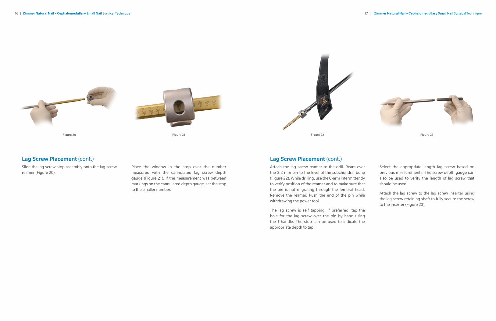
Lag Screw Placement (cont.)Slide the lag screw stop assembly onto the lag screw reamer (Figure 20).
Lag Screw Placement (cont.)Attach the lag screw reamer to the drill. Ream over the 3.2 mm pin to the level of the subchondral bone (Figure 22). While drilling, use the C-arm intermittently to verify position of the reamer and to make sure that the pin is not migrating through the femoral head. Remove the reamer. Push the end of the pin while withdrawing the power tool.
The lag screw is self tapping. If preferred, tap the hole for the lag screw over the pin by hand using the T-handle. The stop can be used to indicate the appropriate depth to tap.
Select the appropriate length lag screw based on previous measurements. The screw depth gauge can also be used to verify the length of lag screw that should be used.
Attach the lag screw to the lag screw inserter using the lag screw retaining shaft to fully secure the screw to the inserter (Figure 23).
Figure 20 Figure 22Figure 21 Figure 23
Place the window in the stop over the number measured with the cannulated lag screw depth gauge (Figure 21). If the measurement was between markings on the cannulated depth gauge, set the stop to the smaller number.
18 | Zimmer Natural Nail – Cephalomedullary Small Nail Surgical Technique 19 | Zimmer Natural Nail – Cephalomedullary Small Nail Surgical Technique
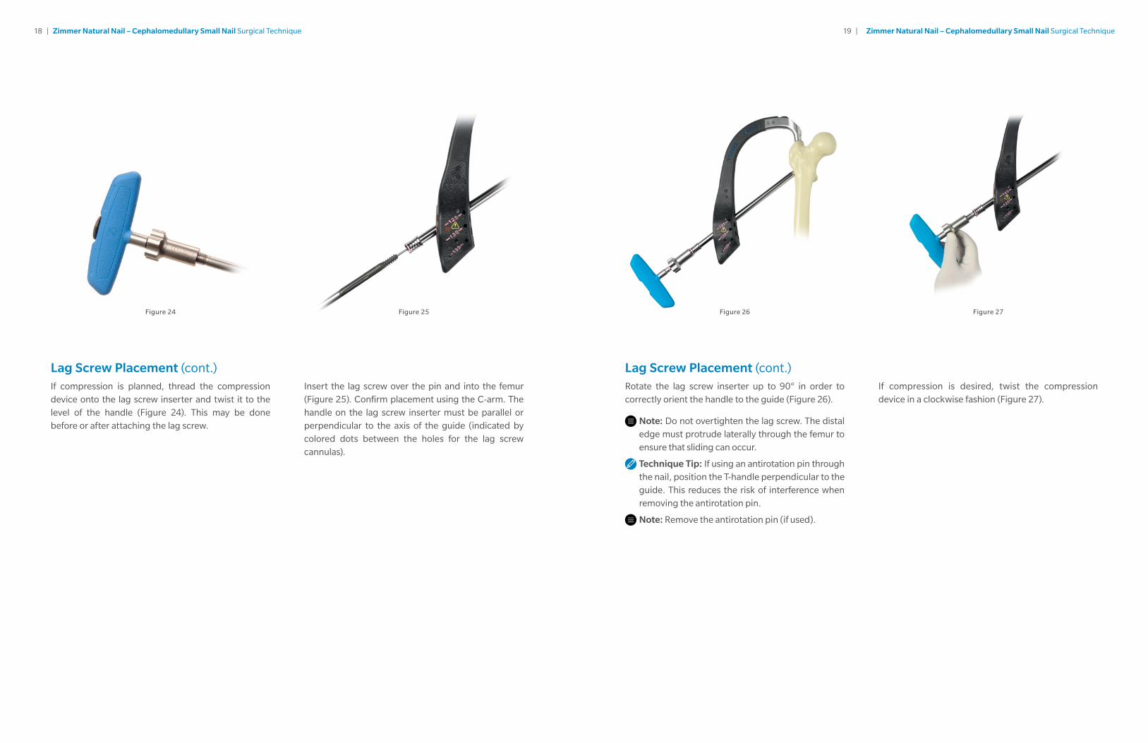
Lag Screw Placement (cont.)If compression is planned, thread the compression device onto the lag screw inserter and twist it to the level of the handle (Figure 24). This may be done before or after attaching the lag screw.
Figure 24 Figure 26Figure 25 Figure 27
Insert the lag screw over the pin and into the femur (Figure 25). Confirm placement using the C-arm. The handle on the lag screw inserter must be parallel or perpendicular to the axis of the guide (indicated by colored dots between the holes for the lag screw cannulas).
Lag Screw Placement (cont.)Rotate the lag screw inserter up to 90° in order to correctly orient the handle to the guide (Figure 26).
Note: Do not overtighten the lag screw. The distal edge must protrude laterally through the femur to ensure that sliding can occur.
Technique Tip: If using an antirotation pin through the nail, position the T-handle perpendicular to the guide. This reduces the risk of interference when removing the antirotation pin.
Note: Remove the antirotation pin (if used).
If compression is desired, twist the compression device in a clockwise fashion (Figure 27).
20 | Zimmer Natural Nail – Cephalomedullary Small Nail Surgical Technique 21 | Zimmer Natural Nail – Cephalomedullary Small Nail Surgical Technique
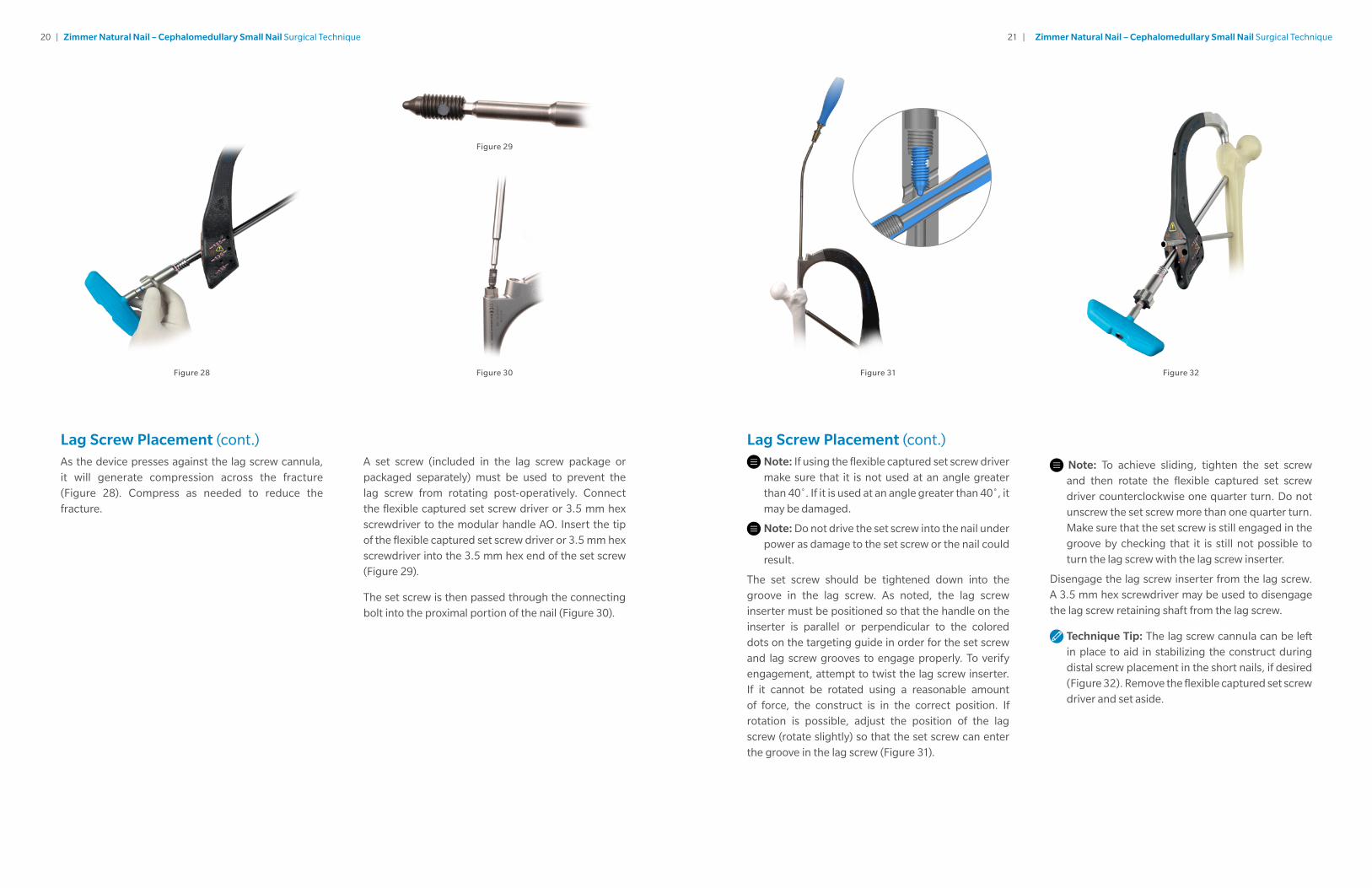
A set screw (included in the lag screw package or packaged separately) must be used to prevent the lag screw from rotating post-operatively. Connect the flexible captured set screw driver or 3.5 mm hex screwdriver to the modular handle AO. Insert the tip of the flexible captured set screw driver or 3.5 mm hex screwdriver into the 3.5 mm hex end of the set screw (Figure 29).
The set screw is then passed through the connecting bolt into the proximal portion of the nail (Figure 30).
Lag Screw Placement (cont.)As the device presses against the lag screw cannula, it will generate compression across the fracture (Figure 28). Compress as needed to reduce the fracture.
Figure 28 Figure 31Figure 30 Figure 32
Figure 29
Lag Screw Placement (cont.)
Note: If using the flexible captured set screw driver make sure that it is not used at an angle greater than 40˚. If it is used at an angle greater than 40˚, it may be damaged.
Note: Do not drive the set screw into the nail under power as damage to the set screw or the nail could result.
The set screw should be tightened down into the groove in the lag screw. As noted, the lag screw inserter must be positioned so that the handle on the inserter is parallel or perpendicular to the colored dots on the targeting guide in order for the set screw and lag screw grooves to engage properly. To verify engagement, attempt to twist the lag screw inserter. If it cannot be rotated using a reasonable amount of force, the construct is in the correct position. If rotation is possible, adjust the position of the lag screw (rotate slightly) so that the set screw can enter the groove in the lag screw (Figure 31).
Note: To achieve sliding, tighten the set screw and then rotate the flexible captured set screw driver counterclockwise one quarter turn. Do not unscrew the set screw more than one quarter turn. Make sure that the set screw is still engaged in the groove by checking that it is still not possible to turn the lag screw with the lag screw inserter.
Disengage the lag screw inserter from the lag screw. A 3.5 mm hex screwdriver may be used to disengage the lag screw retaining shaft from the lag screw.
Technique Tip: The lag screw cannula can be left in place to aid in stabilizing the construct during distal screw placement in the short nails, if desired (Figure 32). Remove the flexible captured set screw driver and set aside.
22 | Zimmer Natural Nail – Cephalomedullary Small Nail Surgical Technique 23 | Zimmer Natural Nail – Cephalomedullary Small Nail Surgical Technique
Distal Targeting for Short Nails Color coded instruments are also used for distal targeting of short nails. For the small targeting guide, instruments marked orange are utilized to place the distal screws. The chart above details the color coded instruments that are used for distal targeting and distal screw placement.
Warning: The small targeting guide is designed to target the distal static (ST) and dynamic (DY) holes in short nails. As the guide is designed to work with both left and right ST and DY holes, care must be taken to ensure that the correct targeting holes (left or right) are used for drilling and screw placement. At this point in the surgery, with the guide oriented horizontally and the nail in place, the correct holes are on the top (anterior) side of the guide. A yellow caution symbol is engraved on the face of the guide near the ST/DY holes to remind the surgeon to take note of the placement of the screw. Additionally, the words “LEFT” and “RIGHT” are embossed in red on the appropriate side of the guide where the screw cannulas should be placed to insert these screws.
Assemble the trocar to the 8.0 mm cannula. Pass the cannula through the appropriate hole in the targeting guide to target the distal hole or slot. The hole is labeled ST is for the Static Hole. The hole labeled DY is for the Dynamic Slot.
After pressing the tip of the trocar and cannula against the skin, make a small incision at that point through the skin and fascia lata. Spread the soft tissue down to the bone. Advance the cannula down to the bone.
Caution: Do not impact on the cannula or trocar, as the tip of the cannula may skive along the bone and prevent accurate targeting.
Remove the trocar (if used) and insert the 4.3 mm drill sleeve into the cannula.
Utilize the 4.3 mm drill bit to drill through both cortices of bone. The depth of the hole can be measured using calibrations on the drill bit. Another option is to remove the drill bit and the drill sleeve and then use the screw depth gauge to measure the depth of the hole.
Caution: In cases where hard cortical bone is encountered, or at the surgeon’s preference, a 5.0 mm tap can be used to ease insertion of the screws.
Instrument Type Small
8.0 mm Screw Cannula Orange
4.3 mm Drill Sleeve Orange–Red
4.3 mm Drill Bit Orange–Red
Screwdriver Orange
Screw Depth Gauge Orange
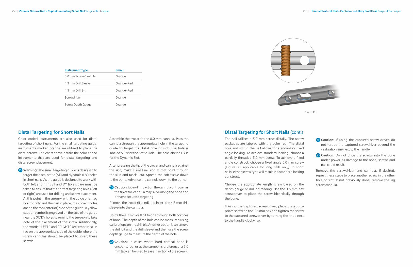
Distal Targeting for Short Nails (cont.)The nail utilizes a 5.0 mm screw distally. The screw packages are labeled with the color red. The distal hole and slot in the nail allows for standard or fixed angle locking. To achieve standard locking, choose a partially threaded 5.0 mm screw. To achieve a fixed angle construct, choose a fixed angle 5.0 mm screw (Figure 33, applicable for long nails only). In short nails, either screw type will result in a standard locking construct.
Choose the appropriate length screw based on the depth gauge or drill bit reading. Use the 3.5 mm hex screwdriver to place the screw bicortically through the bone.
If using the captured screwdriver, place the appro-priate screw on the 3.5 mm hex and tighten the screw to the captured screwdriver by turning the knob next to the handle clockwise.
Caution: If using the captured screw driver, do not torque the captured screwdriver beyond the calibration line next to the handle.
Caution: Do not drive the screws into the bone under power, as damage to the bone, screws and nail could result.
Remove the screwdriver and cannula. If desired, repeat these steps to place another screw in the other hole or slot. If not previously done, remove the lag screw cannula.
Figure 33
24 | Zimmer Natural Nail – Cephalomedullary Small Nail Surgical Technique 25 | Zimmer Natural Nail – Cephalomedullary Small Nail Surgical Technique
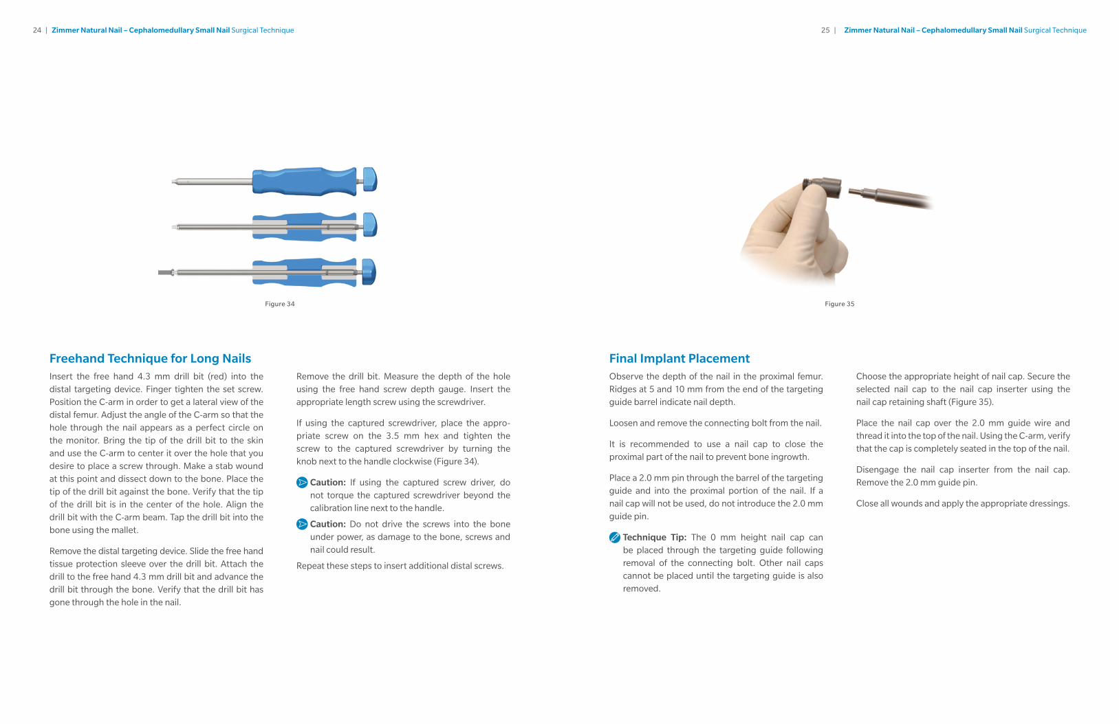
Freehand Technique for Long NailsInsert the free hand 4.3 mm drill bit (red) into the distal targeting device. Finger tighten the set screw. Position the C-arm in order to get a lateral view of the distal femur. Adjust the angle of the C-arm so that the hole through the nail appears as a perfect circle on the monitor. Bring the tip of the drill bit to the skin and use the C-arm to center it over the hole that you desire to place a screw through. Make a stab wound at this point and dissect down to the bone. Place the tip of the drill bit against the bone. Verify that the tip of the drill bit is in the center of the hole. Align the drill bit with the C-arm beam. Tap the drill bit into the bone using the mallet.
Remove the distal targeting device. Slide the free hand tissue protection sleeve over the drill bit. Attach the drill to the free hand 4.3 mm drill bit and advance the drill bit through the bone. Verify that the drill bit has gone through the hole in the nail.
Remove the drill bit. Measure the depth of the hole using the free hand screw depth gauge. Insert the appropriate length screw using the screwdriver.
If using the captured screwdriver, place the appro-priate screw on the 3.5 mm hex and tighten the screw to the captured screwdriver by turning the knob next to the handle clockwise (Figure 34).
Caution: If using the captured screw driver, do not torque the captured screwdriver beyond the calibration line next to the handle.
Caution: Do not drive the screws into the bone under power, as damage to the bone, screws and nail could result.
Repeat these steps to insert additional distal screws.
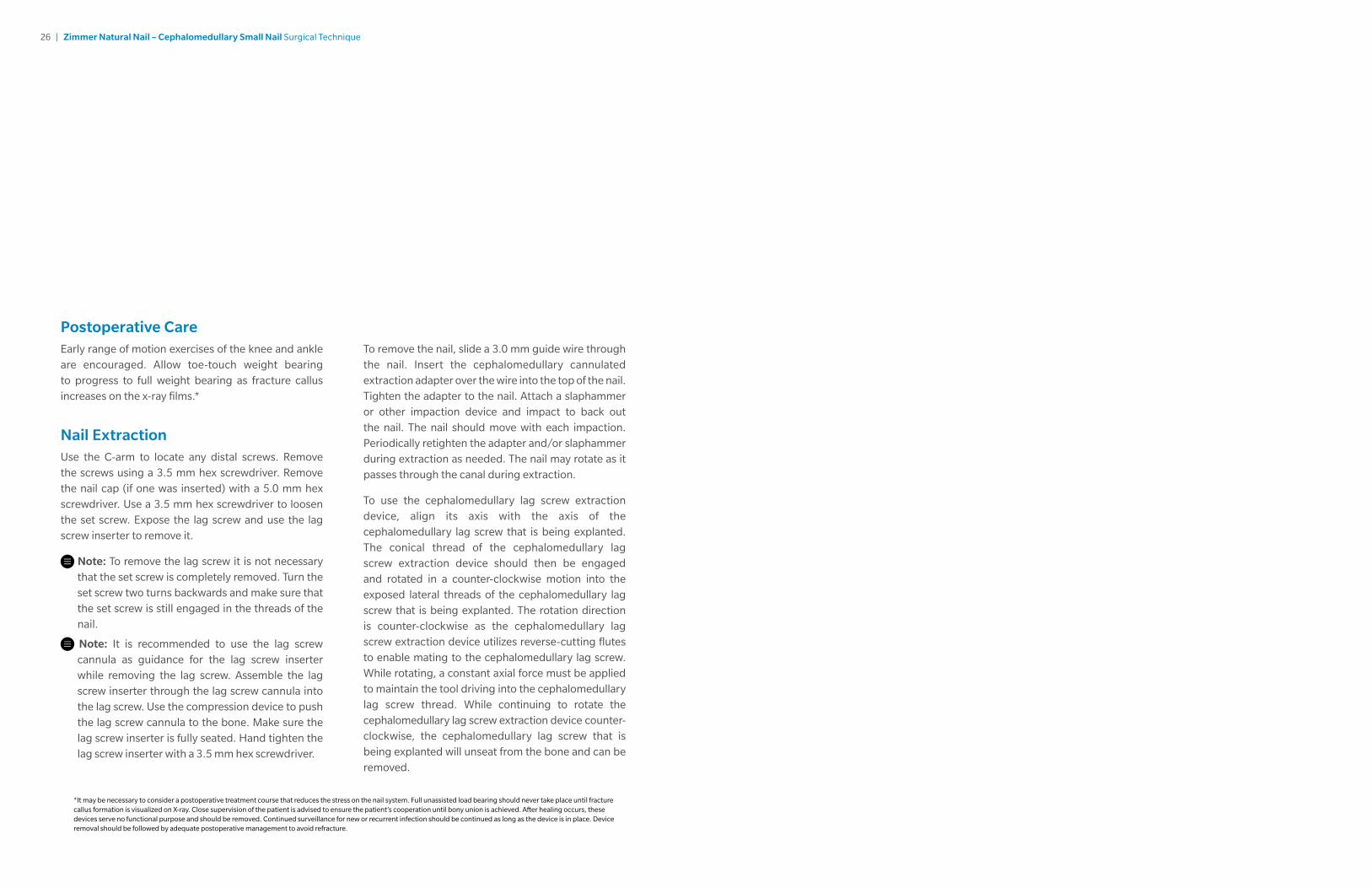
Choose the appropriate height of nail cap. Secure the selected nail cap to the nail cap inserter using the nail cap retaining shaft (Figure 35).
Place the nail cap over the 2.0 mm guide wire and thread it into the top of the nail. Using the C-arm, verify that the cap is completely seated in the top of the nail.
Disengage the nail cap inserter from the nail cap. Remove the 2.0 mm guide pin.
Close all wounds and apply the appropriate dressings.
Final Implant PlacementObserve the depth of the nail in the proximal femur. Ridges at 5 and 10 mm from the end of the targeting guide barrel indicate nail depth.
Loosen and remove the connecting bolt from the nail.
It is recommended to use a nail cap to close the proximal part of the nail to prevent bone ingrowth.
Place a 2.0 mm pin through the barrel of the targeting guide and into the proximal portion of the nail. If a nail cap will not be used, do not introduce the 2.0 mm guide pin.
Technique Tip: The 0 mm height nail cap can be placed through the targeting guide following removal of the connecting bolt. Other nail caps cannot be placed until the targeting guide is also removed.
Figure 34 Figure 35
26 | Zimmer Natural Nail – Cephalomedullary Small Nail Surgical Technique
Postoperative CareEarly range of motion exercises of the knee and ankle are encouraged. Allow toe-touch weight bearing to progress to full weight bearing as fracture callus increases on the x-ray films.*
Nail ExtractionUse the C-arm to locate any distal screws. Remove the screws using a 3.5 mm hex screwdriver. Remove the nail cap (if one was inserted) with a 5.0 mm hex screwdriver. Use a 3.5 mm hex screwdriver to loosen the set screw. Expose the lag screw and use the lag screw inserter to remove it.
Note: To remove the lag screw it is not necessary that the set screw is completely removed. Turn the set screw two turns backwards and make sure that the set screw is still engaged in the threads of the nail.
Note: It is recommended to use the lag screw cannula as guidance for the lag screw inserter while removing the lag screw. Assemble the lag screw inserter through the lag screw cannula into the lag screw. Use the compression device to push the lag screw cannula to the bone. Make sure the lag screw inserter is fully seated. Hand tighten the lag screw inserter with a 3.5 mm hex screwdriver.
To remove the nail, slide a 3.0 mm guide wire through the nail. Insert the cephalomedullary cannulated extraction adapter over the wire into the top of the nail. Tighten the adapter to the nail. Attach a slaphammer or other impaction device and impact to back out the nail. The nail should move with each impaction. Periodically retighten the adapter and/or slaphammer during extraction as needed. The nail may rotate as it passes through the canal during extraction.
To use the cephalomedullary lag screw extraction device, align its axis with the axis of the cephalomedullary lag screw that is being explanted. The conical thread of the cephalomedullary lag screw extraction device should then be engaged and rotated in a counter-clockwise motion into the exposed lateral threads of the cephalomedullary lag screw that is being explanted. The rotation direction is counter-clockwise as the cephalomedullary lag screw extraction device utilizes reverse-cutting flutes to enable mating to the cephalomedullary lag screw. While rotating, a constant axial force must be applied to maintain the tool driving into the cephalomedullary lag screw thread. While continuing to rotate the cephalomedullary lag screw extraction device counter-clockwise, the cephalomedullary lag screw that is being explanted will unseat from the bone and can be removed.
*It may be necessary to consider a postoperative treatment course that reduces the stress on the nail system. Full unassisted load bearing should never take place until fracture callus formation is visualized on X-ray. Close supervision of the patient is advised to ensure the patient’s cooperation until bony union is achieved. After healing occurs, these devices serve no functional purpose and should be removed. Continued surveillance for new or recurrent infection should be continued as long as the device is in place. Device removal should be followed by adequate postoperative management to avoid refracture.
28 | Zimmer Natural Nail – Cephalomedullary Small Nail Surgical Technique 29 | Zimmer Natural Nail – Cephalomedullary Small Nail Surgical Technique
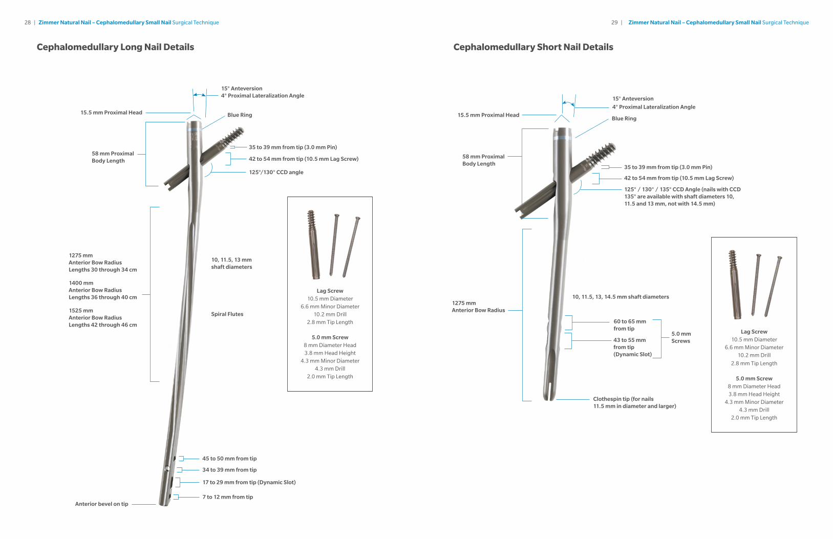
15.5 mm Proximal Head Blue Ring
15° Anteversion 4° Proximal Lateralization Angle
35 to 39 mm from tip (3.0 mm Pin)
42 to 54 mm from tip (10.5 mm Lag Screw)
7 to 12 mm from tip
17 to 29 mm from tip (Dynamic Slot)
34 to 39 mm from tip
45 to 50 mm from tip
Anterior bevel on tip
125°/130° CCD angle
58 mm Proximal Body Length
1275 mm Anterior Bow Radius Lengths 30 through 34 cm
1400 mm Anterior Bow Radius Lengths 36 through 40 cm
1525 mm Anterior Bow Radius Lengths 42 through 46 cm
10, 11.5, 13 mm shaft diameters
Spiral Flutes
4° Proximal Lateralization Angle
10, 11.5, 13, 14.5 mm shaft diameters
60 to 65 mm from tip
43 to 55 mm from tip (Dynamic Slot)
Clothespin tip (for nails 11.5 mm in diameter and larger)
15.5 mm Proximal Head
58 mm Proximal Body Length
1275 mm Anterior Bow Radius
35 to 39 mm from tip (3.0 mm Pin)
42 to 54 mm from tip (10.5 mm Lag Screw)
Blue Ring
5.0 mm Screws
15° Anteversion
125° / 130° / 135° CCD Angle (nails with CCD 135° are available with shaft diameters 10, 11.5 and 13 mm, not with 14.5 mm)
Cephalomedullary Long Nail Details Cephalomedullary Short Nail Details
Lag Screw 10.5 mm Diameter
6.6 mm Minor Diameter 10.2 mm Drill
2.8 mm Tip Length
5.0 mm Screw 8 mm Diameter Head 3.8 mm Head Height
4.3 mm Minor Diameter 4.3 mm Drill
2.0 mm Tip Length
Lag Screw10.5 mm Diameter
6.6 mm Minor Diameter10.2 mm Drill
2.8 mm Tip Length
5.0 mm Screw8 mm Diameter Head3.8 mm Head Height
4.3 mm Minor Diameter4.3 mm Drill
2.0 mm Tip Length
30 | Zimmer Natural Nail – Cephalomedullary Small Nail Surgical Technique 31 | Zimmer Natural Nail – Cephalomedullary Small Nail Surgical Technique
Cephalomedullary Short NailsItem Number Product Description
47-2493-210-10 Cephalomedullary Short Nail 10 mm X 21.5 cm 125 CCD Right Ti-6Al-4V Alloy
47-2493-211-10 Cephalomedullary Short Nail 10 mm X 21.5 cm 125 CCD Left Ti-6Al-4V Alloy
47-2493-212-10 Cephalomedullary Short Nail 10 mm X 21.5 cm 130 CCD Right Ti-6Al-4V Alloy
47-2493-213-10 Cephalomedullary Short Nail 10 mm X 21.5 cm 130 CCD Left Ti-6Al-4V Alloy
47-2493-214-10 Cephalomedullary Short Nail 10 mm X 21.5 cm 135 CCD Right Ti-6Al-4V Alloy
47-2493-215-10 Cephalomedullary Short Nail 10 mm X 21.5 cm 135 CCD Left Ti-6Al-4V Alloy
47-2493-210-11 Cephalomedullary Short Nail 11.5 mm X 21.5 cm 125 CCD Right Ti-6Al-4V Alloy
47-2493-211-11 Cephalomedullary Short Nail 11.5 mm X 21.5 cm 125 CCD Left Ti-6Al-4V Alloy
47-2493-212-11 Cephalomedullary Short Nail 11.5 mm X 21.5 cm 130 CCD Right Ti-6Al-4V Alloy
47-2493-213-11 Cephalomedullary Short Nail 11.5 mm X 21.5 cm 130 CCD Left Ti-6Al-4V Alloy
47-2493-214-11 Cephalomedullary Short Nail 11.5 mm X 21.5 cm 135 CCD Right Ti-6Al-4V Alloy
47-2493-215-11 Cephalomedullary Short Nail 11.5 mm X 21.5 cm 135 CCD Left Ti-6Al-4V Alloy
47-2493-210-13 Cephalomedullary Short Nail 13 mm X 21.5 cm 125 CCD Right Ti-6Al-4V Alloy
47-2493-211-13 Cephalomedullary Short Nail 13 mm X 21.5 cm 125 CCD Left Ti-6Al-4V Alloy
47-2493-212-13 Cephalomedullary Short Nail 13 mm X 21.5 cm 130 CCD Right Ti-6Al-4V Alloy
47-2493-213-13 Cephalomedullary Short Nail 13 mm X 21.5 cm 130 CCD Left Ti-6Al-4V Alloy
47-2493-214-13 Cephalomedullary Short Nail 13 mm X 21.5 cm 135 CCD Right Ti-6Al-4V Alloy
47-2493-215-13 Cephalomedullary Short Nail 13 mm X 21.5 cm 135 CCD Left Ti-6Al-4V Alloy
47-2493-210-14 Cephalomedullary Short Nail 14.5 mm X 21.5 cm 125 CCD Right Ti-6Al-4V Alloy
47-2493-211-14 Cephalomedullary Short Nail 14.5 mm X 21.5 cm 125 CCD Left Ti-6Al-4V Alloy
47-2493-212-14 Cephalomedullary Short Nail 14.5 mm X 21.5 cm 130 CCD Right Ti-6Al-4V Alloy
47-2493-213-14 Cephalomedullary Short Nail 14.5 mm X 21.5 cm 130 CCD Left Ti-6Al-4V Alloy
Cephalomedullary Long NailsItem Number Product Description
47-2493-300-10 Cephalomedullary Long Nail 10 mm X 30 cm 125 CCD Right Ti-6Al-4V Alloy
47-2493-301-10 Cephalomedullary Long Nail 10 mm X 30 cm 125 CCD Left Ti-6Al-4V Alloy
47-2493-302-10 Cephalomedullary Long Nail 10 mm X 30 cm 130 CCD Right Ti-6Al-4V Alloy
47-2493-303-10 Cephalomedullary Long Nail 10 mm X 30 cm 130 CCD Left Ti-6Al-4V Alloy
47-2493-320-10 Cephalomedullary Long Nail 10 mm X 32 cm 125 CCD Right Ti-6Al-4V Alloy
47-2493-321-10 Cephalomedullary Long Nail 10 mm X 32 cm 125 CCD Left Ti-6Al-4V Alloy
47-2493-322-10 Cephalomedullary Long Nail 10 mm X 32 cm 130 CCD Right Ti-6Al-4V Alloy
47-2493-323-10 Cephalomedullary Long Nail 10 mm X 32 cm 130 CCD Left Ti-6Al-4V Alloy
47-2493-340-10 Cephalomedullary Long Nail 10 mm X 34 cm 125 CCD Right Ti-6Al-4V Alloy
47-2493-341-10 Cephalomedullary Long Nail 10 mm X 34 cm 125 CCD Left Ti-6Al-4V Alloy
47-2493-342-10 Cephalomedullary Long Nail 10 mm X 34 cm 130 CCD Right Ti-6Al-4V Alloy
47-2493-343-10 Cephalomedullary Long Nail 10 mm X 34 cm 130 CCD Left Ti-6Al-4V Alloy
47-2493-360-10 Cephalomedullary Long Nail 10 mm X 36 cm 125 CCD Right Ti-6Al-4V Alloy
47-2493-361-10 Cephalomedullary Long Nail 10 mm X 36 cm 125 CCD Left Ti-6Al-4V Alloy
47-2493-362-10 Cephalomedullary Long Nail 10 mm X 36 cm 130 CCD Right Ti-6Al-4V Alloy
47-2493-363-10 Cephalomedullary Long Nail 10 mm X 36 cm 130 CCD Left Ti-6Al-4V Alloy
47-2493-380-10 Cephalomedullary Long Nail 10 mm X 38 cm 125 CCD Right Ti-6Al-4V Alloy
47-2493-381-10 Cephalomedullary Long Nail 10 mm X 38 cm 125 CCD Left Ti-6Al-4V Alloy
47-2493-382-10 Cephalomedullary Long Nail 10 mm X 38 cm 130 CCD Right Ti-6Al-4V Alloy
47-2493-383-10 Cephalomedullary Long Nail 10 mm X 38 cm 130 CCD Left Ti-6Al-4V Alloy
47-2493-400-10 Cephalomedullary Long Nail 10 mm X 40 cm 125 CCD Right Ti-6Al-4V Alloy
47-2493-401-10 Cephalomedullary Long Nail 10 mm X 40 cm 125 CCD Left Ti-6Al-4V Alloy
47-2493-402-10 Cephalomedullary Long Nail 10 mm X 40 cm 130 CCD Right Ti-6Al-4V Alloy
Product Information
Cephalomedullary Long Nails (cont.)Item Number Product Description
47-2493-403-10 Cephalomedullary Long Nail 10 mm X 40 cm 130 CCD Left Ti-6Al-4V Alloy
47-2493-420-10 Cephalomedullary Long Nail 10 mm X 42 cm 125 CCD Right Ti-6Al-4V Alloy
47-2493-421-10 Cephalomedullary Long Nail 10 mm X 42 cm 125 CCD Left Ti-6Al-4V Alloy
47-2493-422-10 Cephalomedullary Long Nail 10 mm X 42 cm 130 CCD Right Ti-6Al-4V Alloy
47-2493-423-10 Cephalomedullary Long Nail 10 mm X 42 cm 130 CCD Left Ti-6Al-4V Alloy
47-2493-440-10 Cephalomedullary Long Nail 10 mm X 44 cm 125 CCD Right Ti-6Al-4V Alloy
47-2493-441-10 Cephalomedullary Long Nail 10 mm X 44 cm 125 CCD Left Ti-6Al-4V Alloy
47-2493-442-10 Cephalomedullary Long Nail 10 mm X 44 cm 130 CCD Right Ti-6Al-4V Alloy
47-2493-443-10 Cephalomedullary Long Nail 10 mm X 44 cm 130 CCD Left Ti-6Al-4V Alloy
47-2493-460-10 Cephalomedullary Long Nail 10 mm X 46 cm 125 CCD Right Ti-6Al-4V Alloy
47-2493-461-10 Cephalomedullary Long Nail 10 mm X 46 cm 125 CCD Left Ti-6Al-4V Alloy
47-2493-462-10 Cephalomedullary Long Nail 10 mm X 46 cm 130 CCD Right Ti-6Al-4V Alloy
47-2493-463-10 Cephalomedullary Long Nail 10 mm X 46 cm 130 CCD Left Ti-6Al-4V Alloy
47-2493-300-11 Cephalomedullary Long Nail 11.5 mm X 30 cm 125 CCD Right Ti-6Al-4V Alloy
47-2493-301-11 Cephalomedullary Long Nail 11.5 mm X 30 cm 125 CCD Left Ti-6Al-4V Alloy
47-2493-302-11 Cephalomedullary Long Nail 11.5 mm X 30 cm 130 CCD Right Ti-6Al-4V Alloy
47-2493-303-11 Cephalomedullary Long Nail 11.5 mm X 30 cm 130 CCD Left Ti-6Al-4V Alloy
47-2493-320-11 Cephalomedullary Long Nail 11.5 mm X 32 cm 125 CCD Right Ti-6Al-4V Alloy
47-2493-321-11 Cephalomedullary Long Nail 11.5 mm X 32 cm 125 CCD Left Ti-6Al-4V Alloy
47-2493-322-11 Cephalomedullary Long Nail 11.5 mm X 32 cm 130 CCD Right Ti-6Al-4V Alloy
47-2493-323-11 Cephalomedullary Long Nail 11.5 mm X 32 cm 130 CCD Left Ti-6Al-4V Alloy
47-2493-340-11 Cephalomedullary Long Nail 11.5 mm X 34 cm 125 CCD Right Ti-6Al-4V Alloy
47-2493-341-11 Cephalomedullary Long Nail 11.5 mm X 34 cm 125 CCD Left Ti-6Al-4V Alloy
Item Number Product Description
47-2493-342-11 Cephalomedullary Long Nail 11.5 mm X 34 cm 130 CCD Right Ti-6Al-4V Alloy
47-2493-343-11 Cephalomedullary Long Nail 11.5 mm X 34 cm 130 CCD Left Ti-6Al-4V Alloy
47-2493-360-11 Cephalomedullary Long Nail 11.5 mm X 36 cm 125 CCD Right Ti-6Al-4V Alloy
47-2493-361-11 Cephalomedullary Long Nail 11.5 mm X 36 cm 125 CCD Left Ti-6Al-4V Alloy
47-2493-362-11 Cephalomedullary Long Nail 11.5 mm X 36 cm 130 CCD Right Ti-6Al-4V Alloy
47-2493-363-11 Cephalomedullary Long Nail 11.5 mm X 36 cm 130 CCD Left Ti-6Al-4V Alloy
47-2493-380-11 Cephalomedullary Long Nail 11.5 mm X 38 cm 125 CCD Right Ti-6Al-4V Alloy
47-2493-381-11 Cephalomedullary Long Nail 11.5 mm X 38 cm 125 CCD Left Ti-6Al-4V Alloy
47-2493-382-11 Cephalomedullary Long Nail 11.5 mm X 38 cm 130 CCD Right Ti-6Al-4V Alloy
47-2493-383-11 Cephalomedullary Long Nail 11.5 mm X 38 cm 130 CCD Left Ti-6Al-4V Alloy
47-2493-400-11 Cephalomedullary Long Nail 11.5 mm X 40 cm 125 CCD Right Ti-6Al-4V Alloy
47-2493-401-11 Cephalomedullary Long Nail 11.5 mm X 40 cm 125 CCD Left Ti-6Al-4V Alloy
47-2493-402-11 Cephalomedullary Long Nail 11.5 mm X 40 cm 130 CCD Right Ti-6Al-4V Alloy
47-2493-403-11 Cephalomedullary Long Nail 11.5 mm X 40 cm 130 CCD Left Ti-6Al-4V Alloy
47-2493-420-11 Cephalomedullary Long Nail 11.5 mm X 42 cm 125 CCD Right Ti-6Al-4V Alloy
47-2493-421-11 Cephalomedullary Long Nail 11.5 mm X 42 cm 125 CCD Left Ti-6Al-4V Alloy
47-2493-422-11 Cephalomedullary Long Nail 11.5 mm X 42 cm 130 CCD Right Ti-6Al-4V Alloy
47-2493-423-11 Cephalomedullary Long Nail 11.5 mm X 42 cm 130 CCD Left Ti-6Al-4V Alloy
47-2493-440-11 Cephalomedullary Long Nail 11.5 mm X 44 cm 125 CCD Right Ti-6Al-4V Alloy
47-2493-441-11 Cephalomedullary Long Nail 11.5 mm X 44 cm 125 CCD Left Ti-6Al-4V Alloy
47-2493-442-11 Cephalomedullary Long Nail 11.5 mm X 44 cm 130 CCD Right Ti-6Al-4V Alloy
47-2493-443-11 Cephalomedullary Long Nail 11.5 mm X 44 cm 130 CCD Left Ti-6Al-4V Alloy
47-2493-460-11 Cephalomedullary Long Nail 11.5 mm X 46 cm 125 CCD Right Ti-6Al-4V Alloy
32 | Zimmer Natural Nail – Cephalomedullary Small Nail Surgical Technique 33 | Zimmer Natural Nail – Cephalomedullary Small Nail Surgical Technique
Cephalomedullary Long Nails (cont.)Item Number Product Description
47-2493-461-11 Cephalomedullary Long Nail 11.5 mm X 46 cm 125 CCD Left Ti-6Al-4V Alloy
47-2493-462-11 Cephalomedullary Long Nail 11.5 mm X 46 cm 130 CCD Right Ti-6Al-4V Alloy
47-2493-463-11 Cephalomedullary Long Nail 11.5 mm X 46 cm 130 CCD Left Ti-6Al-4V Alloy
47-2493-300-13 Cephalomedullary Long Nail 13 mm X 30 cm 125 CCD Right Ti-6Al-4V Alloy
47-2493-301-13 Cephalomedullary Long Nail 13 mm X 30 cm 125 CCD Left Ti-6Al-4V Alloy
47-2493-302-13 Cephalomedullary Long Nail 13 mm X 30 cm 130 CCD Right Ti-6Al-4V Alloy
47-2493-303-13 Cephalomedullary Long Nail 13 mm X 30 cm 130 CCD Left Ti-6Al-4V Alloy
47-2493-320-13 Cephalomedullary Long Nail 13 mm X 32 cm 125 CCD Right Ti-6Al-4V Alloy
47-2493-321-13 Cephalomedullary Long Nail 13 mm X 32 cm 125 CCD Left Ti-6Al-4V Alloy
47-2493-322-13 Cephalomedullary Long Nail 13 mm X 32 cm 130 CCD Right Ti-6Al-4V Alloy
47-2493-323-13 Cephalomedullary Long Nail 13 mm X 32 cm 130 CCD Left Ti-6Al-4V Alloy
47-2493-340-13 Cephalomedullary Long Nail 13 mm X 34 cm 125 CCD Right Ti-6Al-4V Alloy
47-2493-341-13 Cephalomedullary Long Nail 13 mm X 34 cm 125 CCD Left Ti-6Al-4V Alloy
47-2493-342-13 Cephalomedullary Long Nail 13 mm X 34 cm 130 CCD Right Ti-6Al-4V Alloy
47-2493-343-13 Cephalomedullary Long Nail 13 mm X 34 cm 130 CCD Left Ti-6Al-4V Alloy
47-2493-360-13 Cephalomedullary Long Nail 13 mm X 36 cm 125 CCD Right Ti-6Al-4V Alloy
47-2493-361-13 Cephalomedullary Long Nail 13 mm X 36 cm 125 CCD Left Ti-6Al-4V Alloy
47-2493-362-13 Cephalomedullary Long Nail 13 mm X 36 cm 130 CCD Right Ti-6Al-4V Alloy
47-2493-363-13 Cephalomedullary Long Nail 13 mm X 36 cm 130 CCD Left Ti-6Al-4V Alloy
47-2493-380-13 Cephalomedullary Long Nail 13 mm X 38 cm 125 CCD Right Ti-6Al-4V Alloy
47-2493-381-13 Cephalomedullary Long Nail 13 mm X 38 cm 125 CCD Left Ti-6Al-4V Alloy
47-2493-382-13 Cephalomedullary Long Nail 13 mm X 38 cm 130 CCD Right Ti-6Al-4V Alloy
47-2493-383-13 Cephalomedullary Long Nail 13 mm X 38 cm 130 CCD Left Ti-6Al-4V Alloy
Item Number Product Description
47-2493-400-13 Cephalomedullary Long Nail 13 mm X 40 cm 125 CCD Right Ti-6Al-4V Alloy
47-2493-401-13 Cephalomedullary Long Nail 13 mm X 40 cm 125 CCD Left Ti-6Al-4V Alloy
47-2493-402-13 Cephalomedullary Long Nail 13 mm X 40 cm 130 CCD Right Ti-6Al-4V Alloy
47-2493-403-13 Cephalomedullary Long Nail 13 mm X 40 cm 130 CCD Left Ti-6Al-4V Alloy
47-2493-420-13 Cephalomedullary Long Nail 13 mm X 42 cm 125 CCD Right Ti-6Al-4V Alloy
47-2493-421-13 Cephalomedullary Long Nail 13 mm X 42 cm 125 CCD Left Ti-6Al-4V Alloy
47-2493-422-13 Cephalomedullary Long Nail 13 mm X 42 cm 130 CCD Right Ti-6Al-4V Alloy
47-2493-423-13 Cephalomedullary Long Nail 13 mm X 42 cm 130 CCD Left Ti-6Al-4V Alloy
47-2493-440-13 Cephalomedullary Long Nail 13 mm X 44 cm 125 CCD Right Ti-6Al-4V Alloy
47-2493-441-13 Cephalomedullary Long Nail 13 mm X 44 cm 125 CCD Left Ti-6Al-4V Alloy
47-2493-442-13 Cephalomedullary Long Nail 13 mm X 44 cm 130 CCD Right Ti-6Al-4V Alloy
47-2493-443-13 Cephalomedullary Long Nail 13 mm X 44 cm 130 CCD Left Ti-6Al-4V Alloy
47-2493-460-13 Cephalomedullary Long Nail 13 mm X 46 cm 125 CCD Right Ti-6Al-4V Alloy
47-2493-461-13 Cephalomedullary Long Nail 13 mm X 46 cm 125 CCD Left Ti-6Al-4V Alloy
47-2493-462-13 Cephalomedullary Long Nail 13 mm X 46 cm 130 CCD Right Ti-6Al-4V Alloy
47-2493-463-13 Cephalomedullary Long Nail 13 mm X 46 cm 130 CCD Left Ti-6Al-4V Alloy
10.5 mm Lag ScrewsItem Number Product Description
47-2485-070-10 10.5 mm Lag Screw 70 mm Length Ti-6Al-4V Alloy
47-2485-075-10 10.5 mm Lag Screw 75 mm Length Ti-6Al-4V Alloy
47-2485-080-10 10.5 mm Lag Screw 80 mm Length Ti-6Al-4V Alloy
47-2485-085-10 10.5 mm Lag Screw 85mm Length Ti-6Al-4V Alloy
47-2485-090-10 10.5 mm Lag Screw 90 mm Length Ti-6Al-4V Alloy
47-2485-095-10 10.5 mm Lag Screw 95 mm Length Ti-6Al-4V Alloy
47-2485-100-10 10.5 mm Lag Screw 100 mm Length Ti-6Al-4V Alloy
47-2485-105-10 10.5 mm Lag Screw 105 mm Length Ti-6Al-4V Alloy
47-2485-110-10 10.5 mm Lag Screw 110 mm Length Ti-6Al-4V Alloy
47-2485-115-10 10.5 mm Lag Screw 115 mm Length Ti-6Al-4V Alloy
47-2485-120-10 10.5 mm Lag Screw 120 mm Length Ti-6Al-4V Alloy
47-2485-125-10 10.5 mm Lag Screw 125 mm Length Ti-6Al-4V Alloy
47-2485-130-10 10.5 mm Lag Screw 130 mm Length Ti-6Al-4V Alloy
5.0 mm Screws (for distal screw holes)Item Number Product Description
47-2483-020-50 5.0 mm Cortical Screw 20 mm Length Ti-6Al-4V Alloy Partially Threaded 3.5 mm Hex Head
47-2483-022-50 5.0 mm Cortical Screw 22.5 mm Length Ti-6Al-4V Alloy Partially Threaded 3.5 mm Hex Head
47-2483-025-50 5.0 mm Cortical Screw 25 mm Length Ti-6Al-4V Alloy Partially Threaded 3.5 mm Hex Head
47-2483-027-50 5.0 mm Cortical Screw 27.5 mm Length Ti-6Al-4V Alloy Partially Threaded 3.5 mm Hex Head
47-2483-030-50 5.0 mm Cortical Screw 30 mm Length Ti-6Al-4V Alloy Partially Threaded 3.5 mm Hex Head
47-2483-032-50 5.0 mm Cortical Screw 32.5 mm Length Ti-6Al-4V Alloy Partially Threaded 3.5 mm Hex Head
47-2483-035-50 5.0 mm Cortical Screw 35 mm Length Ti-6Al-4V Alloy Partially Threaded 3.5 mm Hex Head
47-2483-037-50 5.0 mm Cortical Screw 37.5 mm Length Ti-6Al-4V Alloy Partially Threaded 3.5 mm Hex Head
47-2483-040-50 5.0 mm Cortical Screw 40 mm Length Ti-6Al-4V Alloy Partially Threaded 3.5 mm Hex Head
47-2483-042-50 5.0 mm Cortical Screw 42.5 mm Length Ti-6Al-4V Alloy Partially Threaded 3.5 mm Hex Head
47-2483-045-50 5.0 mm Cortical Screw 45 mm Length Ti-6Al-4V Alloy Partially Threaded 3.5 mm Hex Head
47-2483-047-50 5.0 mm Cortical Screw 47.5 mm Length Ti-6Al-4V Alloy Partially Threaded 3.5 mm Hex Head
Item Number Product Description
47-2483-050-50 5.0 mm Cortical Screw 50 mm Length Ti-6Al-4V Alloy Partially Threaded 3.5 mm Hex Head
47-2483-052-50 5.0 mm Cortical Screw 52.5 mm Length Ti-6Al-4V Alloy Partially Threaded 3.5 mm Hex Head
47-2483-055-50 5.0 mm Cortical Screw 55 mm Length Ti-6Al-4V Alloy Partially Threaded 3.5 mm Hex Head
47-2483-057-50 5.0 mm Cortical Screw 57.5 mm Length Ti-6Al-4V Alloy Partially Threaded 3.5 mm Hex Head
47-2483-060-50 5.0 mm Cortical Screw 60 mm Length Ti-6Al-4V Alloy Partially Threaded 3.5 mm Hex Head
47-2483-065-50 5.0 mm Cortical Screw 65 mm Length Ti-6Al-4V Alloy Partially Threaded 3.5 mm Hex Head
47-2483-070-50 5.0 mm Cortical Screw 70 mm Length Ti-6Al-4V Alloy Partially Threaded 3.5 mm Hex Head
47-2483-075-50 5.0 mm Cortical Screw 75 mm Length Ti-6Al-4V Alloy Partially Threaded 3.5 mm Hex Head
47-2483-080-50 5.0 mm Cortical Screw 80 mm Length Ti-6Al-4V Alloy Partially Threaded 3.5 mm Hex Head
47-2483-085-50 5.0 mm Cortical Screw 85 mm Length Ti-6Al-4V Alloy Partially Threaded 3.5 mm Hex Head
47-2483-090-50 5.0 mm Cortical Screw 90 mm Length Ti-6Al-4V Alloy Partially Threaded 3.5 mm Hex Head
47-2483-095-50 5.0 mm Cortical Screw 95 mm Length Ti-6Al-4V Alloy Partially Threaded 3.5 mm Hex Head
47-2483-100-50 5.0 mm Cortical Screw 100 mm Length Ti-6Al-4V Alloy Partially Threaded 3.5 mm Hex Head
47-2484-020-50 5.0 mm Cortical Screw 20 mm Length Ti-6Al-4V Alloy Fixed Angle 3.5 mm Hex Head
47-2484-022-50 5.0 mm Cortical Screw 22.5 mm Length Ti-6Al-4V Alloy Fixed Angle 3.5 mm Hex Head
47-2484-025-50 5.0 mm Cortical Screw 25 mm Length Ti-6Al-4V Alloy Fixed Angle 3.5 mm Hex Head
47-2484-027-50 5.0 mm Cortical Screw 27.5 mm Length Ti-6Al-4V Alloy Fixed Angle 3.5 mm Hex Head
47-2484-030-50 5.0 mm Cortical Screw 30 mm Length Ti-6Al-4V Alloy Fixed Angle 3.5 mm Hex Head
47-2484-032-50 5.0 mm Cortical Screw 32.5 mm Length Ti-6Al-4V Alloy Fixed Angle 3.5 mm Hex Head
47-2484-035-50 5.0 mm Cortical Screw 35 mm Length Ti-6Al-4V Alloy Fixed Angle 3.5 mm Hex Head
47-2484-037-50 5.0 mm Cortical Screw 37.5 mm Length Ti-6Al-4V Alloy Fixed Angle 3.5 mm Hex Head
47-2484-040-50 5.0 mm Cortical Screw 40 mm Length Ti-6Al-4V Alloy Fixed Angle 3.5 mm Hex Head
34 | Zimmer Natural Nail – Cephalomedullary Small Nail Surgical Technique 35 | Zimmer Natural Nail – Cephalomedullary Small Nail Surgical Technique
5.0 mm Screws (for distal screw holes) (cont.)
KT-2490-003-02 – SMALL Cephalomedullary Nail Instrument Set (cont.)
Item Number Product Description
47-2484-042-50 5.0 mm Cortical Screw 42.5 mm Length Ti-6Al-4V Alloy Fixed Angle 3.5 mm Hex Head
47-2484-045-50 5.0 mm Cortical Screw 45 mm Length Ti-6Al-4V Alloy Fixed Angle 3.5 mm Hex Head
47-2484-047-50 5.0 mm Cortical Screw 47.5 mm Length Ti-6Al-4V Alloy Fixed Angle 3.5 mm Hex Head
47-2484-050-50 5.0 mm Cortical Screw 50 mm Length Ti-6Al-4V Alloy Fixed Angle 3.5 mm Hex Head
47-2484-052-50 5.0 mm Cortical Screw 52.5 mm Length Ti-6Al-4V Alloy Fixed Angle 3.5 mm Hex Head
47-2484-055-50 5.0 mm Cortical Screw 55 mm Length Ti-6Al-4V Alloy Fixed Angle 3.5 mm Hex Head
47-2484-057-50 5.0 mm Cortical Screw 57.5 mm Length Ti-6Al-4V Alloy Fixed Angle 3.5 mm Hex Head
47-2484-060-50 5.0 mm Cortical Screw 60 mm Length Ti-6Al-4V Alloy Fixed Angle 3.5 mm Hex Head
47-2484-065-50 5.0 mm Cortical Screw 65 mm Length Ti-6Al-4V Alloy Fixed Angle 3.5 mm Hex Head
47-2484-070-50 5.0 mm Cortical Screw 70 mm Length Ti-6Al-4V Alloy Fixed Angle 3.5 mm Hex Head
47-2484-075-50 5.0 mm Cortical Screw 75 mm Length Ti-6Al-4V Alloy Fixed Angle 3.5 mm Hex Head
47-2484-080-50 5.0 mm Cortical Screw 80 mm Length Ti-6Al-4V Alloy Fixed Angle 3.5 mm Hex Head
47-2484-085-50 5.0 mm Cortical Screw 85 mm Length Ti-6Al-4V Alloy Fixed Angle 3.5 mm Hex Head
47-2484-090-50 5.0 mm Cortical Screw 90 mm Length Ti-6Al-4V Alloy Fixed Angle 3.5 mm Hex Head
47-2484-095-50 5.0 mm Cortical Screw 95 mm Length Ti-6Al-4V Alloy Fixed Angle 3.5 mm Hex Head
47-2484-100-50 5.0 mm Cortical Screw 100 mm Length Ti-6Al-4V Alloy Fixed Angle 3.5 mm Hex Head
Nail Caps / Set ScrewItem Number Product Description
47-2487-002-00 Cephalomedullary Nail Cap 0 mm Height Ti-6AL-4V Alloy
47-2487-002-05 Cephalomedullary Nail Cap 5 mm Height Ti-6AL-4V Alloy
47-2487-002-10 Cephalomedullary Nail Cap 10 mm Height Ti-6AL-4V Alloy
47-2487-002-15 Cephalomedullary Nail Cap 15 mm Height Ti-6AL-4V Alloy
47-2493-000-00 Cephalomedullary Nail Set Screw Ti-6AL-4V Alloy
Item Number Product Description Qty
00-2490-043-80 Screw Cannula 8 mm - Short 1
00-2490-046-20 2.0 mm Pin 2
00-2490-046-32 Guide Pin Inserter / Extractor 1
00-2490-050-01 Modular Handle AO 1
00-2490-050-02 Modular T-Handle 1
00-2490-060-10 Cephalomedullary Lag Screw Cannula - Short 1
00-2490-062-10 Cephalomedullary Lag Screw Trocar - Short 1
00-2490-062-80 Short Screw Trocar 8.0 mm 1
00-2490-063-10 Cephalomedullary Lag Screw Pin Sleeve 3.2 mm - Short
1
00-2490-063-43 Short Drill Sleeve 4.3 mm 1
00-2490-064-43 Calibrated Drill 4.3 mm Short 2
00-2490-065-80 Short Screw Depth Gauge 8.0 mm 1
00-2490-066-43 Calibrated Drill 4.3 mm - Cephalomedullary 2
00-2490-070-00 Free Hand Targeting Wand 1
00-2490-073-00 Free Hand Targeting Depth Gauge 1
00-2490-074-00 Free Hand Tissue Protection Sleeve 1
00-2490-075-43 4.3 mm Free Hand Drill 152.5 mm 2
00-2490-080-00 Nail Cap Inserter 1
00-2490-080-03 Nail Cap Retaining Shaft 1
00-2490-081-43 Cephalomedullary Lag Screw Drill Sleeve 4.3 mm
1
00-2490-090-11 Cephalomedullary Extraction Adapter Cannulated
1
00-2490-450-32 3.2 mm Threaded Pin 3
00-5900-099-00 Case Lid 2
KT-2490-003-02 – SMALL Cephalomedullary Nail Instrument SetItem Number Product Description Qty
00-2490-000-30 Nail Diameter Gauge 1
00-2490-000-33 Ruler 1
00-2490-000-34 Nail Length Gauge 1
00-2490-000-41 Hole Indicator 2
00-2490-003-03 Cephalomedullary Connecting Bolt - Small 2
00-2490-003-08 Cephalomedullary Targeting Guide - Small 1
00-2490-003-45 Cephalomedullary Lag Screw Stop Assembly 2
00-2490-003-49 Cephalomedullary Lag Screw Compression Device
1
00-2490-003-52 Cephalomedullary Lag Screw Inserter - Short 1
00-2490-003-53 Cephalomedullary Lag Screw Retaining Shaft - Short
1
00-2490-003-64 Cephalomedullary Lag Screw Reamer - Short 1
00-2490-003-68 Cephalomedullary Lag Screw Tap - Short 1
00-2490-010-01 Short Cannulated Awl 1
00-2490-012-00 Guide Wire Gripper 1
00-2490-012-30 3.0 mm Threaded Pin By 305 mm 3
00-2490-013-00 Entry Cannula 1
00-2490-013-01 Entry Cannula Starting Point Locator 1
00-2490-014-15 Cephalomedullary Tapered Reamer 15.5 mm 1
00-2490-014-80 Entry Reamer 8 mm 1
00-2490-017-00 Guide Wire Pusher 1
00-2490-024-00 Reduction Finger 1
00-2490-031-05 11 mm Hex / Pin Wrench 2
00-2490-032-00 Impaction Head 1
00-2490-032-05 Slotted Mallet 1
00-2490-032-80 Cephalomedullary Connecting Bolt Inserter 8 mm
1
00-2490-033-00 Slap Hammer Adapter 1
00-2490-035-03 Cephalomedullary Screwdriver, 3.5 mm Hex 1
00-2490-035-06 Cephalomedullary Flexible Captured Set Screw Driver - Small
1
00-2490-035-60 Short Modular Screwdriver 3.5 mm Hex 2
00-2490-035-62 Captured Screwdriver 3.5 mm Hex - Small 1
00-2490-035-72 Captured Screwdriver 3.5 mm Hex - Freehand
1
00-2490-035-75 Free Hand Modular 3.5 mm Hex Screwdriver 2
00-2490-037-80 Cephalomedullary Cannulated Screw Depth Gauge - Short
1
Instrument Cases (Select both “Stainless Steel” or both “Stainless Steel and Aluminum” Cases)Item Number Product Description Qty
00-2490-040-50 Cephalomedullary Small Case 1 of 2 - Stainless Steel and Aluminium
1
00-2490-063-50 Cephalomedullary Small Case 2 of 2 - Stainless Steel and Aluminium
1
00-2490-040-00 Cephalomedullary Small Case 1 of 2 - Stainless Steel
1
00-2490-063-00 Cephalomedullary Small Case 2 of 2 - Stainless Steel
1
Optional InstrumentsItem Number Product Description Qty
00-2490-14-03 Inner Channel Reamer 1
00-2490-14-04 Inner Channel Reamer Sleeve 1
00-2490-030-14 Small Antrotation Pin 1
00-2490-048-50 Long 5.0 mm Tap 1
00-2490-041-14 Small Double Barrel Cannula 1
00-2490-072-43 Free Hand Targeting Drill 4.3 mm 2
00-2490-091-11 Cephalomedullary Extraction Rod - M11 Thread
1
00-2490-455-32 3.2 mm Non-Threaded Pin (SMALL) 3
00-2490-090-12 Cephalomedullary Lag Screw Extraction Device
Ball Tip Guide Wire (available separately)Item Number Product Description
00-2255-008-01 3.0 mm Ball Tip Guide Wire 100 cm
47-2255-008-01 3.0 mm Ball Tip Guide Wire 100 cm (Sterile)
00-2255-008-00 2.4 mm Ball Tip Guide Wire 70 cm
47-2255-008-00 2.4 mm Ball Tip Guide Wire 70 cm (Sterile)
Tear Drop Guide Wire (available separately)Item Number Product Description
47-2490-097-00 3.0 mm x 100 cm Tear Drop Guide Wire (Sterile)
47-2490-098-00 3.0 mm x 70 cm Tear Drop Guide Wire (Sterile)
47-2490-097-01 2.4 mm x 100 cm Tear Drop Guide Wire (Sterile)
47-2490-098-01 2.4 mm x 70 cm Tear Drop Guide Wire (Sterile)
Wall Chart97-2493-003-00
X-ray Templates:Cephalomedullary Short: 06.02075.000/97-2493-051-00 (US Only)Cephalomedullary Long: 06.02087.000/97-2493-050-00 (US Only)

36 | Zimmer Natural Nail – Cephalomedullary Small Nail Surgical Technique
Notes
References
1. Baumgaertner et. al., The Value of the Tip-apex Distance in Predicting Failure of Fixation of Peritrochanteric Fractures of the Hip, J Bone Joint Surg AM. 1995:77:1058-1064
2. AO Principles of Fracture Management, Thieme, 2000
3. Browner, Bruce et. al., Skeletal Trauma, 2 Vol Set, “Basic Science, Management, and Reconstruction”, 2003, p 1929 - 1931
97-2493-005-00 Rev. 7 11/16
Zimmer Biomet does not practice medicine. This technique was developed in conjunction with health care professionals. This document is intended for surgeons and is not intended for laypersons. Each surgeon should exercise his or her own independent judgment in the diagnosis and treatment of an individual patient, and this information does not purport to replace the comprehensive training surgeons have received. As with all surgical procedures, the technique used in each case will depend on the surgeon’s medical judgment as the best treatment for each patient. Results will vary based on health, weight, activity and other variables. Not all patients are candidates for this product and/or procedure. Caution: Federal (USA) law restricts this device to sale by or on the order of a surgeon. Rx only.
All content herein is protected by copyright, trademarks and other intellectual property rights, as applicable, owned by or licensed to Zimmer Biomet or its affiliates unless otherwise indicated, and must not be redistributed, duplicated or disclosed, in whole or in part, without the express written consent of Zimmer Biomet.
Distribution to any other recipient is prohibited. For product in-formation, including indications, contraindications, warnings, precautions, potential adverse effects and patient counseling information, see the package insert and www.zimmerbiomet.com.
Check for country product clearances and reference product specific instructions for use.
©2016 Zimmer Biomet
Legal ManufacturerZimmer, Inc. 1800 West Center StreetWarsaw, Indiana 46580USA
Zimmer, U.K. Ltd.9 Lancaster PlaceSouth Marston ParkSwindon, SN3 4FP, UK
CE mark on a surgical technique is not valid unless there is a CE mark on the product label.
Products within this surgical technique are under the design control of various manufacturers. Refer to the product labeling of each device for the legal manufacturer.
0086Legal ManufacturerZimmer GmbHSulzerallee 88404 WinterthurSwitzerland
Representative in the USAZimmer, Inc.1800 West Center St.Warsaw, Indiana 46580 USA
www.zimmerbiomet.com