zilog macro cross assembler - hytherionhytherion.com/beattidp/comput/zmasm/zmasm_book.pdftable 2-14...
TRANSCRIPT
UM003601-COR1299
Zilog Macro Cross Assembler
User’s Manual

UM003601-COR1299
©1999 by ZiLOG, Inc. All rights reserved. Information in this publication concerning the devices, applications, or technology described is intended to suggest possible uses and may be superseded. ZiLOG, INC. DOES NOT ASSUME LIABILITY FOR OR PROVIDE A REPRESENTATION OF ACCURACY OF THE INFORMATION, DEVICES, OR TECH-NOLOGY DESCRIBED IN THIS DOCUMENT. ZiLOG ALSO DOES NOT ASSUME LIABILITY FOR INTELLECTUAL PROPERTY INFRINGEMENT RELATED IN ANY MANNER TO USE OF INFORMATION, DEVICES, OR TECHNOLOGY DESCRIBED HEREIN OR OTHERWISE. Except with the express written approval of ZiLOG, use of information, devices, or technology as critical components of life support systems is not authorized. No licenses are conveyed, implicitly or otherwise, by this document under any intellectual property rights.
ZiLOG
, Inc. 910 East Hamilton Ave., Suite 110Campbell, CA 95008Telephone: (408) 558-8500FAX: (408) 558-8300Internet: http://www.zilog.com

UM003601-COR1299 i
ABOUT THIS MANUAL
We recommend that you read and understand everything in this manual before setting up and using the product. However, we recognize that users have different styles of learning. Therefore, we have designed this manual to be used either as a how-to procedural manual or a reference guide to important data.
The following conventions have been adopted to provide clarity and ease of use:
■
Universe Medium 10-point
all-caps is used to highlight the following items:
– commands , displayed messages
– menu selections, pop-up lists, button, fields, or dialog boxes
– modes
– pins and ports
– program or application name
– instructions, registers, signals and subroutines
– an action performed by the software
– icons
■
Courier Regular 10-point
is used to highlight the following items
– bit
– software code
– file names and paths
ii UM003601-COR1299
– hexadecimal value
■
Grouping of Actions Within A Procedure Step
– Actions in a procedure step are all performed on the same window or dialog box. Actionsperformed on different windows or dialog boxes appear in separate steps.
UM003601-COR1299 iii
Chapter Title and Subsections Page
T
ABLE
O
F
C
ONTENTS
Chapter 1 Introduction
Introduction...................................................................................................................................1-1ZMASM Development Environment .............................................................................................1-3Understanding Relocatable Assembly .........................................................................................1-4
Chapter 2 Assembler Description
Introduction...................................................................................................................................2-1Assembler Overview ....................................................................................................................2-2Source Statement Format ............................................................................................................2-4Assembler Symbols....................................................................................................................2-13Assembler Reserved Words.......................................................................................................2-16Assembler Operators .................................................................................................................2-23Assembler Expressions..............................................................................................................2-25Structured Assembly Outputs.....................................................................................................2-41Conditional Assembly.................................................................................................................2-41Conditional Assembly Inputs ......................................................................................................2-42Conditional Assembly Processing ..............................................................................................2-50
Chapter 3 Macro Language
Introduction...................................................................................................................................3-1Using Macros ...............................................................................................................................3-3Referencing System Symbols ....................................................................................................3-14

iv UM003601-COR1299
Chapter Title and Subsections Page
Chapter 4 Linker Description
Introduction ...................................................................................................................................4-1Invoking the Linker........................................................................................................................4-5Linker Options...............................................................................................................................4-6The Link Map File .......................................................................................................................4-11
Appendix A DOS-Version Assembler and Linker
Invoking the Assembler ............................................................................................................... A-1Invoking the Linker..................................................................................................................... A-10
Appendix B Utilities Description
ZFIXUP........................................................................................................................................ B-1
Appendix C Assembler and Linker Error Messages
assembler errors..........................................................................................................................C-1LINKER errors ...........................................................................................................................C-27
Appendix D Importing From Other Assemblers
Introduction ..................................................................................................................................D-1
Appendix E ASCII Character Set
A
ppendix F Sample of Output File Printouts
Output Files .................................................................................................................................G-1.MAP file ......................................................................................................................................G-1.HEX file.......................................................................................................................................G-8.SYM file ....................................................................................................................................G-30
Glossary

UM003601-COR1299 vii
Figure Page
L
IST
OF
F
IGURES
Figure 1-1 Cross Assembler Functional Relationship........................................................... 1-3Figure 1-2 Assembly Language Programs ........................................................................... 1-5Figure 2-1 Cross Assembler SimpliÞed Block Diagram ........................................................ 2-3Figure 2-2 Restricted, Reserved, and Special Assembler Symbols ................................... 2-15Figure 2-3 General Format of Conditional Inputs ............................................................... 2-43Figure 3-1 General Format of Macro DeÞnition .................................................................... 3-5Figure 3-2 Example of a Nested Macro DeÞnition ................................................................ 3-6Figure 3-3 Macro DeÞnition, Call, and Expansion .............................................................. 3-11Figure 4-1 Linker Functional Relationship ............................................................................ 4-3Figure 4-2 Linker Components ............................................................................................. 4-6Figure 4-3 Sample Symbol File .......................................................................................... 4-21Figure A-1 Linker Components .......................................................................................... A-10

UM003601-COR1299 ix
Table Page
L
IST
OF
T
ABLES
Table 2-1 Character Constant Escape Sequences ................................................................................. 2-5Table 2-2 Character Constant Escape Sequences ............................................................................... 2-11Table 2-3 String Constants Escape Sequences.................................................................................... 2-13Table 2-4 Assembler Directives.......................................................................................................... 2-16Table 2-5 Mnemonic Operators .......................................................................................................... 2-17Table 2-6 Z8 MCU Machine Instructions........................................................................................... 2-18Table 2-7 Z8 MCU Registers.............................................................................................................. 2-18Table 2-8 Z8 MCU Condition Flags ................................................................................................... 2-18Table 2-9 Z8 MCU Interrupt Vectors ................................................................................................. 2-19Table 2-10 Z89C00 AND Z893XX DSP MCU Machine Instructions ................................................. 2-19Table 2-11 Z89C00 AND Z893XX DSP MCU Registers .................................................................... 2-19Table 2-12 Z89C00 AND Z893XX DSP MCU Condition Flags ......................................................... 2-19Table 2-13 Z89C00 AND Z893XX DSP MCU Interrupt Vectors ....................................................... 2-19Table 2-14 Z180 Processor Machine Instructions ................................................................................ 2-20Table 2-15 Z180 Processor Registers ................................................................................................... 2-20Table 2-16 Z180 Processor Condition Flags......................................................................................... 2-21Table 2-17 Z380 Processor Machine Instructions ................................................................................ 2-21Table 2-18 Z380 Processor Registers ................................................................................................... 2-22Table 2-19 Z380 Processor Condition Flags......................................................................................... 2-22Table 2-20 Assembler Expression Operators........................................................................................ 2-23Table 2-21 Types of Expressions.......................................................................................................... 2-27Table 2-22 Assembler Directives for Structured Assembly ................................................................. 2-30Table 2-23 Assembler Directives for Conditional Assembly ............................................................... 2-42Table 2-24 Assembler Directive Set Summary..................................................................................... 2-55Table 2-25 Number of Addresses per Initializer................................................................................... 2-69Table 2-26 Number of Addresses per Initializer................................................................................... 2-71Table 2-27 Number of Addresses per Initializer................................................................................... 2-78Table 2-28 Z8 Family Control Section Address Spaces ....................................................................... 2-81Table 2-29 Hybrid Z8/Z89C00 Family Control Section Address Spaces............................................. 2-82Table 2-30 Z89C00 Family Control Section Address Spaces .............................................................. 2-83Table 2-31 Print Assembler Directive Options................................................................................... 2-113

UM003601-COR1299 x
Table Page
Table 2-32 Supported Types ............................................................................................................... 2-126Table 2-33 Vector Locations............................................................................................................... 2-129Table 2-34 Z89C00 Family Vectors ................................................................................................... 2-130Table 3-1 Macro Assembler Instructions.............................................................................................. 3-2Table 3-2 Examples of Symbol Substitution and Concantenation...................................................... 3-12Table 3-3 System Symbol Names and Descriptions ........................................................................... 3-14Table 4-1 Acronyms and Abbreviations ............................................................................................... 4-4Table A-1 Command Line Options....................................................................................................... A-2Table A-2 Summary of Linker Options .............................................................................................. A-12Table A-3 Summary of Linker Commands......................................................................................... A-13

UM003601-COR1299 1–1
Z
I
LOG M
ACRO
C
ROSS
A
SSEMBLER
C
HAPTER
1
I
NTRODUCTION
INTRODUCTION
In addition to providing all that is necessary to install the Zilog Macro Cross Assembler (ZMASM) software, this chapter introduces two basic concepts that can greatly simplify your target application development:
1. The “ZMASM Development Environment” section briefly describes how this software product isused in conjunction with other tools that make up the Zilog ZMASM development environment.
2. The “Understanding Relocatable Assembly” section lists and explains some of the obviousbenefits of
modular programming
when compared to writing programs in one larger file.
The third section, “Getting Started”, lists the minimum and recommended system requirements nec-essary to run the ZMASM software and shows you the simple procedure for installing the ZMASM software diskette so you can begin building a target application program of your own.
Chapter Topics:ZMASM Development Environment
Understanding Relocatable Assembly
Getting Started
– System Requirements
– Installing the ZMASM Software

Introduction
Introduction
1–2 UM003601-COR1299
ZMASM Key Features
■
Dual Processor Chips (Z8 and DSP) in the Same Source File
■
Structured Assembly and Data Code
■
Source-Level Debug Support
■
Built-In Register Equates
■
Linker
Topics Covered in Other Chapters:
Using the Assembler . . . . . . . . . . . . . . . . . . . . . . . . . . . . . . Chapter 2
Assembler Syntax and Directives . . . . . . . . . . . . . . . . . . . Chapter 3
Macro Language . . . . . . . . . . . . . . . . . . . . . . . . . . . . . . . . . Chapter 4
Linker Description . . . . . . . . . . . . . . . . . . . . . . . . . . . . . . . . Chapter 5

UM003601-COR1299 1–3
Introduction
ZMASM Development Environment
ZMASM DEVELOPMENT ENVIRONMENT
ZMASM is the principal software tool of the ZMASM development environment supporting Zilog’s family of microcontrollers. It is designed to be used in conjunction with the other tools of the assem-bler development environment, which enhances programmer productivity.
The assembler development environment enables users to develop software in assembler lan-guage, including assembly, debug, OTP programming, and ROM code submission. Using the Mi-crosoft Windows-based project interface, the user can easily manage large numbers of source files so only the minimum number of required files are reassembled when source code changes are made. The assembler takes a source file containing assembly language statements and translates it into a corresponding object file. It can produce a listing file containing the source code, object code, and comments. The assembler supports macros, structure assembly, and conditional assem-bly.
The functional relationship of the assembler to other elements of the ZMASM development environ-ment is shown in
Figure 1-1.
Figure 1-1.
Cross Assembler Functional Relationship
Text Editor
Assembler SourceCode Files
Cross Assembler
RelocatableObject Files
ExecutableLoad File
AssemblerListing Files
C Compiler
Object FilesLibraries
Linker
Source Debug
Hex ConversionUtility ZDUMP
EPROMProgrammer
C LanguageSource Files
andMap File
File
Understanding Relocatable Assembly
Introduction
1–4 UM003601-COR1299
UNDERSTANDING RELOCATABLE ASSEMBLY
Relocation is a process whereby a program is broken up into smaller individual modules or files, assembled separately, and then rejoined together to create the final binary object file that is to be executed. Relocation is precisely the mechanism to achieve high-level top-down design, top-down coding, and top-down testing.
The relocation process of breaking a program into smaller modules, or modular programming, permits greater programmer efficiency for many reasons:
1. Easier to conceptualize in smaller modules.
2. Easier and faster to edit smaller modules.
3. Easier and faster to debug and verify smaller modules.
4. Easier and faster to reassemble only the modules that have errors in the debug process.
5. Can assemble larger programs using the same host computer memory size.
6. Reduces global variables which enhances understanding and improves maintenance andreliability.
To understand the relocation and linking concepts, consider the assembly language program in Fig-ure 1-2a, which shows a program written in one long file. This program has been simplified to ease the reader's understanding, but the concept can easily be expanded to larger programs. To convert this program into several relocatable files, the first step is to find logical breaks and create smaller files as shown in Figure 1-2b. This usually is done by separating the program in functional blocks, such as “startup”, “main”, “input_output”, and other logical groups of subroutines. Then each file is examined for symbols that are referenced in that file but not defined. For each of these symbols, they must be defined in this file as “external”, which means they will be defined in some other file as “global”. For each symbol that will be used by another file, it must be defined as “global” so the “external” reference of the other file will be satisfied. This is shown in Figure 1-2c.

UM003601-COR1299 1–5
Introduction
Understanding Relocatable Assembly
Figure 1-2.
Assembly Language Programs
program.src
data1data2data3data4start
clear data3clear data4...store data1...store data2
call subr1
call subr2
jump loop
subr1load data1add data2store data3return
subr2load data1sub data2store data3return
end
program1.src
data1data2data3data4start
clear data3clear data4...store data1...store data2
call subr1
call subr2
jump loopend
subr1load data1add data2store data3returnend
subr2load data1sub data2store data3returnend
program2.src
program3.src
global data1, data2, data3external subr1, subr2
data1data2data3start
clear data3...store data1...store data2
call subr1
call subr2
jump loopend
program1.src
global subr1external data1, data2, data3
subr1load data1add data2store data3returnend
program2.src
global subr2external data1, data2, data4
subr2load data1sub data2store data4returnend
program3.srca. One Long File
b. Three Smaller Files
c. Three Relocatable Files

The linker then examines all the cross-referenced global and external symbols and resolves them to an absolute address, thus creating the final absolute address object module. When each individ-ual file is then assembled, the final absolute address is not known and therefore the listing file output from the assembler will show “relative” addresses. Each listing file will show the program counter as starting with a value of zero. When the file is linked, the link map will show the starting address of each file linked. By adding the relative address of the listing file to the starting address of the link map for that file, the absolute address can be determined. As this can make debugging very tedious and error prone due to hexadecimal calculations, ZMASM provides a utility to overcome this. ZFIX-UP, a simple DOS-based utility, does “address fix-ups” by examining the link map file to determine the starting addresses for each file. Then it reads each listing file and simply rewrites the file with the correct addresses as dictated by the link map. (Refer to Appendix B: Utilities Description for more information on the ZFIXUP and other utilities.)
Another important concept for relocation is the use of “sections”. Sections can be thought of as sep-arate logical groupings of memory. The most common usage is to imagine the memory map of an embedded processor system that typically may contain “ram1”, “ram2”, “rom1”, “rom2”, and “i/o”. Sections permit a one-to-one mapping correspondence from assembly language program to phys-ical memory resources. This is also especially important when the memory sections of a similar type (RAM or ROM) are disjointed because it permits easy assignment and control of resources. Sec-tions also permit assembling programs for dual-processor MCUs in one common assembly file. Dual processor MCUs, such as Z89175 and Z89C65, combine the powerful Z8
®
MCU core with the versatile Z89C00 DSP core into a single device for cost-reduced mixed-mode applications.
Finally, to overcome the problems of managing many files, utility programs have been written to ex-amine file dependencies and modification times so only the minimum amount of reassembly is done after an edit session. These utilities are typically called “make” because they help make the final object file. ZMASM includes a simple “make” type utility in its Windows based “project” front end to enhance programmer productivity.
NOTE:
Refer to
Managing the Structured Techniques, Strategies for Software Development inthe 1990's
, Edward Yourdon, third edition, Yourdon Press Prentice Hall, Englewood Cliffs,New Jersey 07632.

UM003601-COR1299 2–1
Z
I
LOG M
ACRO
C
ROSS
A
SSEMBLER
C
HAPTER
2
A
SSEMBLER
D
ESCRIPTION
INTRODUCTION
Zilog’s Macro Assembler (ZMASM) is one of the software tools making up Zilog’s integrated devel-opment environment that supports Zilog’s family of microcontrollers. The assembler, therefore, is designed to be used in conjunction with the other tools that make up the integrated development environment.
The assembler takes a source file containing assembly language statements and translates it into a corresponding object file that is then used by the target application. It also can produce a listing containing the source code, object code, and comments. In addition, the assembler supports mac-ros, structured, and conditional assembly.
The “Assembler Overview” section further describes the basic functions of the assembler. Addition-al sections that follow specifically address such topics as the assembler’s source statement format, constants, symbols, expressions, structured and conditional assembly. This chapter also includes a complete listing and full description of each ZMASM assembler directive and concludes with a listing of all assembly errors and warnings.
Chapter Topics:
Source Statement Format
Assembler Constants
Assembler Symbols
Assembler Operators
Assembler Expressions
Structured and Conditional Assembly
Assembler Directives
Assembler Overview
Assembler Description
2–2 UM003601-COR1299
ASSEMBLER OVERVIEW
The assembler reads a source file that has been generated by the C compiler, or created by the user with a text editor, and creates a relocatable object file. The object file is then linked with other object files and libraries, using the linker. Output from the linker is an executable load file, which may be loaded into the target system and debugged, using the Source Level Debug program, or may be programmed into EPROM or masked ROM, for direct use in the customer’s application see Figure 2-1.
The assembler performs the following primary functions:
■ Converts machine instructions, coded in mnemonic form, to their binary representation, and writesthat representation to a relocatable object file which is suitable for linking with other object files tocreate an absolute load file.
■ Creates an assembler listing file, providing a mapping of the source code statements to theirmachine representation.
■ Allows frequently occurring source sequences to be coded as macros, which can be called outusing a single directive.
■ Provides high-level control structures for decision and loop control to support structured assemblylanguage programming.
■ Supports conditional assembly of portions of a source module.
■ Allows the source module to be split over multiple physical source files, which are processed as asingle entity through a file inclusion mechanism.
■ Performs syntax checking on the source statements, and notify the programmer of invalid forms.
■ Provides debug information to the object module, to support assembler language debugging at thesource module level.

UM003601-COR1299 2–3
Assembler Description Assembler Overview
Figure 2-1. Cross Assembler Simplified Block Diagram
READ STOP
Source Module
Listing File
Object File
Read Source
Expand Macros
Emit Code
Report Error
Conditionally
Is Source Syntax
End of File
Yes
No
Correct?
Excluded?
READ
READ
READ
Source Statement Format Assembler Description
2–4 UM003601-COR1299
SOURCE STATEMENT FORMAT
The assembly language source file lines are called source statements. Source statements are de-limited by the ASCII newline character (ASCII decimal code 10), or by the ASCII character pair car-riage-return plus newline (ASCII decimal code 13 followed by ASCII decimal code 10). The assem-bler source statements are written in free format, and may contain up to 512 ASCII text characters, excluding statement delimiters. Column one of the source statements is reserved for specifying la-bels, that is, only labels may appear in column one, although they need not do so. Apart from this restriction, there are no requirements for certain things to appear in any particular column position. The source statements are divided into fields, which may be of arbitrary length, and appear in any column, except that the fields are positionally dependent with respect to one another, and their com-bined length must not exceed 512 characters.
There are four fields in a source statement, listed here in the order in which they must appear on a source statement:
1. Label Field
2. Operation Field
3. Operand Field
4. Comment Field
The general syntax for source statements is as follows:
[label [:] ] operation [operands] [; comment]

UM003601-COR1299 2–5
Assembler Description Source Statement Format
Some fields of a source statement are upper-case and lower-case sensitive. The following table summarizes case sensitivity:
Table 2-1. Character Constant Escape Sequences
AreaCaseSensitive Examples
Labels/symbols Yes “Start” and “start” are two distinct labels.
Operation codes (machine instructions and assembler directives)
No “LOAD”, “load”, and “Load” are the same.“CHIP”, “chip”, and “Chip” are the same.“MACRO” , “macro”, and “Macro” are the same.
Macro names Yes “Fetch” and “fetch” are two distinct macros.
Operands Yes “AbsSection” and “ABSSection” are two distinct operands.
Reserved symbols No “$F” and “$f” are the same and may not be redefined.
Source Statement Format Assembler Description
2–6 UM003601-COR1299
Assembler Source Statement Label FieldThe label field is optional. If used, it contains a label to identify the source statement. A labeled statement may be referenced by another statement using the statement label. The label is usually assigned the value of the assembler’s location counter. Any valid assembler symbol may be placed in the label field; a label is simply an assembler symbol used in the label field. Sometimes program-mers interchange the usage of ‘label’ and ‘symbol’, but there is a subtle difference.
A statement may contain only one label in the label field. If present, the label must be a valid as-sembler symbol. Labels and symbols are case sensitive; uppercase is distinct from lowercase.
If the label does not begin in column one, the label must be suffixed with a colon (:). If the label is specified in column one, the colon suffix is optional. Whitespace may separate the label and the colon suffix.
Label names and scope are recorded in the assembler's symbol table. Labels must be unique within their scope. Labels need not be unique with respect to machine and assembler directive mnemon-ics. That is, directive mnemonics are not reserved by the assembler.
A label is a local label if its first character is '$'. Local labels have restricted scope, being visible only between the assembler SCOPE or .NEWBLOCK directives which bound their definition. Local la-bels within macro definitions are visible only within that definition.
The symbol ‘$$’ is an anonymous label, and may appear an arbitrary number of times in a source module. Anonymous labels are referenced by the symbols $F and $B, which refer to the nearest forward-referenced anonymous label and the nearest backward anonymous label, respectively.
The period character (.) must appear only in the first character of a label. If the period (.) in any other position within the label, an “Invalid label” error occurs.

UM003601-COR1299 2–7
Assembler Description Source Statement Format
Assembler Source Statement Operation FieldThe operation field contains an operation code. This field contains the symbolic name (mnemonic) for an assembler, machine or macro call directive.
This field is required if the operand field is used, and may be coded in any position after the label field. If the label field is omitted, the operation field may begin in any position after column one, so long as nothing other that whitespace precedes it. If the label field is specified, whitespace may op-tionally separate the label from the operation code.
Operation codes (machine instructions and assembler directives) are not case sensitive; uppercase and lowercase characters are handled exactly the same way. Macro names, however, are com-prised of symbols, and are case sensitive.
Operand Field
The operand field contains operands. This field is optional, depending on the requirements of the specific directive coded in the operation field. It contains one or more operands associated with the directive coded in the operation field.
If more than one operand is used, the individual operands are separated by commas. Whitespace characters may optionally surround the comma separators.
At least one whitespace character must separate the operation and operand fields.
Operands are case sensitive, as they are comprised of symbols.
Comment Field
The comment field is optional; if used, it contains a comment.
Comments are introduced with the comment character (;). After the comment character, any string of ASCII text characters may be coded (except newline, which delimits source statements). The comment character may optionally be separated from a preceding field by coding whitespace char-acters. If there are no preceding fields, the comment character may be specified in the first column, or it may be preceded by whitespace.
If the first character on a source statement is an asterisk (*), then the entire statement is treated as a comment.
Source Statement Format Assembler Description
2–8 UM003601-COR1299
Assembler ConstantsThe assembler constant is a self-defining term whose value is specified explicitly. The assembler supports four kinds of constant:
1. Arithmetic Constants
2. Character Constants
3. String Constants
4. Symbolic Constants
Assembler Arithmetic Constants
The assembler supports the following kinds of arithmetic constant:
■ Binary Integer Constants
■ Octal Integer Constants
■ Decimal Integer Constants
■ Hexadecimal Integer Constants
■ Floating Point Constants
■ Fixed Point Constants
All integral constants are represented internally as signed, 32-bit numbers. If a specified integral constant cannot be represented in 32 bits, it is truncated and a warning is generated.
Integral constants are not sign extended. Thus, the constant 0FFH is equal to 00FF (hexadecimal) or 255 (decimal); it does not equal -1. All floating point constants are represented internally in IEEE 64-bit, double precision, floating point format. If a specified floating point constant cannot be repre-sented in the double precision format, it is truncated and a warning is generated.
Assembler Binary Integer Arithmetic Constants
Binary integer constants are specified by coding the base 2 number suffixed by the letter B (or b). Base 2 numbers are coded using the binary digits 0 through 1.
The following are examples of valid binary integer constants.
00000000B Constant equal to 0 (decimal) or 0 (hexadecimal)
0100000b Constant equal to 32 (decimal) or 20 (hexadecimal)
01b Constant equal to 1 (decimal) or 1 (hexadecimal)

UM003601-COR1299 2–9
Assembler Description Source Statement Format
11111000B Constant equal to 248 (decimal) or 0F8 (hexadecimal)
Assembler Octal Integer Arithmetic Constants
Octal integer constants are specified by coding the base 8 number suffixed by the letter O (or o). Base 8 numbers are coded using the octal digits 0 through 7.
The following are examples of valid octal integer constants.
10O Constant equal to 8 (decimal) or 8 (hexadecimal)
0100000O Constant equal to 32,768 (decimal) or 8,000 (hexadecimal)
226O Constant equal to 150 (decimal) or 96 (hexadecimal)
1232O Constant equal to 666 (decimal) or 29A (hexadecimal)
Assembler Decimal Integer Arithmetic Constants
Base 10 is the default base for arithmetic constants. Decimal integer constant are therefore speci-fied by coding the base 10 number with no prefix or suffix. Base 10 numbers are coded using the decimal digits 0 through 9.
The following are examples of valid decimal integer constants.
1000 Constant equal to 1,000 (decimal) or 3E8 (hexadecimal)
32768 Constant equal to 32,768 (decimal) or 8,000 (hexadecimal)
25 Constant equal to 25 (decimal) or 19 (hexadecimal)
77 Constant equal to 77 (decimal) or 4D (hexadecimal)
Assembler Hexadecimal Integer Arithmetic Constants
Hexadecimal integer constants are specified by coding the base 16 number suffixed by the letter H (or h). Base 16 numbers are coded using the hexadecimal digits 0 through 9 and the letters A through F (uppercase or lowercase). To avoid ambiguity with symbols, hexadecimal integer con-stants must begin with one of the digits 0 through 9.
The following are examples of valid hexadecimal integer constants.
78h Constant equal to 120 (decimal) or 78 (hexadecimal)
0FH Constant equal to 15 (decimal) or 000F (hexadecimal)
37ACh Constant equal to 14,252 (decimal) or 37AC (hexadecimal)
Source Statement Format Assembler Description
2–10 UM003601-COR1299
0abcH Constant equal to 2,748 (decimal) or 0ABC (hexadecimal)
Assembler Floating-Point Arithmetic Constants
A floating-point constant consists of three parts, specified in the following order:
1. Integer Part
2. Fraction Part
3. Exponent Part
Integer Part. The floating-point integral part is mandatory, and consists of one or more decimal dig-its followed by a period.
Fraction Part. The floating-point fraction part is optional. If specified, it consists of one or more dec-imal digits.
Exponent Part. The floating-point exponent part is optional. If specified, it consists of an e or E, optionally followed by a + or -, followed by one or more decimal digits.
The following are examples of valid floating-point arithmetic constants:
1.2
2.e-5
0.5E2
4.0e+2
2.0E3
3E6
Assembler Fixed-Point Arithmetic Constants
Fixed-point arithmetic constants are real numbers in the range [-1,1). That is, fixed-point arithmetic constants are greater than or equal to -1.0, and less than 1.0. These numbers can be used, for ex-ample, in the DF (FRACT) assembler directive, such as:
DF 0.5
UM003601-COR1299 2–11
Assembler Description Source Statement Format
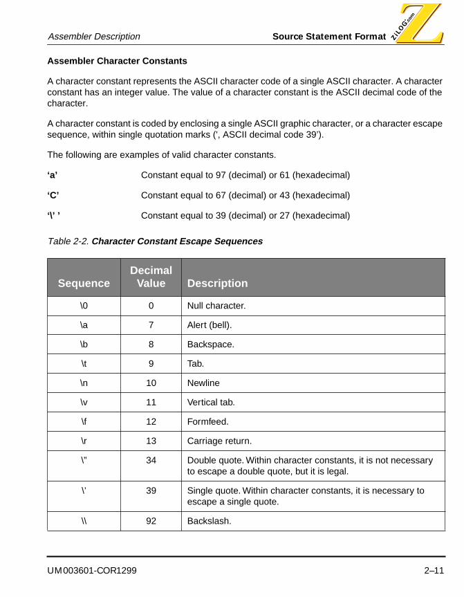
Assembler Character Constants
A character constant represents the ASCII character code of a single ASCII character. A character constant has an integer value. The value of a character constant is the ASCII decimal code of the character.
A character constant is coded by enclosing a single ASCII graphic character, or a character escape sequence, within single quotation marks (', ASCII decimal code 39’).
The following are examples of valid character constants.
‘a’ Constant equal to 97 (decimal) or 61 (hexadecimal)
‘C’ Constant equal to 67 (decimal) or 43 (hexadecimal)
‘\’ ’ Constant equal to 39 (decimal) or 27 (hexadecimal)
Table 2-2. Character Constant Escape Sequences
SequenceDecimal
Value Description
\0 0 Null character.
\a 7 Alert (bell).
\b 8 Backspace.
\t 9 Tab.
\n 10 Newline
\v 11 Vertical tab.
\f 12 Formfeed.
\r 13 Carriage return.
\” 34 Double quote. Within character constants, it is not necessary to escape a double quote, but it is legal.
\’ 39 Single quote. Within character constants, it is necessary to escape a single quote.
\\ 92 Backslash.
Source Statement Format Assembler Description
2–12 UM003601-COR1299
Assembler String Constants
A string constant consists of one or more ASCII graphic characters enclosed in double quotation marks (“, ASCII decimal code 34”). To embed a double quote mark inside the string, the escape character backslash (\) must precede the double quote character. This is the same mechanism used by the C programming language.
Each character in the string must be a single ASCII graphic character, or a character escape se-quence. A null string is represented by an empty pair of matching double quotes.
NOTE: Null character (\0) escape sequence is invalid.
The following are examples of valid string constants.
“version” Defines the 7-character string version.
“Plan \“9\” is done” Defines the 16-character string Plan “9” is done.

UM003601-COR1299 2–13
Assembler Description Assembler Symbols
Character strings are used for the following:
■ File names, as in INCLUDE “filename.s”
■ Section names, as in .SECT “section”
■ Data initialization directives, as in .ASCII “char string”
Assembler Symbolic Constants
A symbolic constant is a named constant. Symbolic constants are defined using the EQU and SET assembler directives.
ASSEMBLER SYMBOLS
An assembler symbol is a single character or combination of characters that is used to represent a label, or an assembler, machine or macro call directive.
Table 2-3. String Constants Escape Sequences
SequenceDecimal
Value Description
\a 7 Alert (bell).
\b 8 Backspace.
\t 9 Tab.
\n 10 Newline
\v 11 Vertical tab.
\f 12 Formfeed.
\r 13 Carriage return.
\’ 34 Single quote. Within a string constant, it is not necessary to escape a single quote, but it is legal.
\” 39 Double quote. Within a string constant, it is not necessary to escape a double quote, but it is legal.
u 92 Backslash.
Assembler Symbols Assembler Description
2–14 UM003601-COR1299
Symbols consist of numeric digits, uppercase or lowercase letters, the special characters: under-score (_), period (.), dollar sign ($), question mark (?), or pound sign (#); or any combination of such digits, letters and characters.
NOTE: For the period (.), this is true only for the first character
Symbols cannot begin with a numeric digit nor with a pound sign (#).
Symbols may be any length greater than zero (0) and less than one hundred twenty eight (128).
Certain symbols are reserved or restricted by the assembler.
Uppercase and lowercase letters are distinct.

UM003601-COR1299 2–15
Assembler Description Assembler Symbols
Assembler Reserved Symbols
The following table summarizes the restricted, reserved and special assembler symbols.
Figure 2-2. Restricted, Reserved, and Special Assembler Symbols
Symbol Description Notes and Restrictions
$ Current value of the location counter This symbol is reserved, meaning that it may not be redefined by the programmer.
$$ Anonymous label. This symbol may be used as a label an arbitrary number of times.
$B Anonymous label backward reference. This symbol referenced the most recent anonymous label defined be-fore the reference. This symbol is reserved: it may not be redefined.
$F Anonymous label forward reference. This symbol referenced the most recent anonymous label defined af-ter the reference. This symbol may not be redefined.
$Lnnnnnn Assembler-generated label. nnnnnn is a six-digit decimal number.
These symbols are used for assem-bler-generated labels, required for structured assembly processing. It is not illegal for the programmer to define a label of this form, but it is the programmer's responsibility to ensure that such programmer-de-fined labels are unique.
Assembler Reserved Words Assembler Description
2–16 UM003601-COR1299
ASSEMBLER RESERVED WORDS
Reserved words consist of register names, condition flags, machine instructions and directives. the use of reserved words must conform to the following rules:
■ Reserved words must not be used as labels. if used as labels, ZMASM will not flag any error;however t these attempts may cause unexpected result in your program.
■ Reserved words must not be used as macro arguments; otherwise, a syntax error will begenerated.
■ Reserved words munt not occur in the firts column, as ZMASM will process it as a label. This maycause unexpected results.
Table 2-4. ASSEMBLER DIRECTIVES
.$BREAK .$CONTINUE .COPY .$ELSE .$ELSEIF .$REPEAT
.$IF .$UNTIL .$WEND .$WHILE .ALIGN .ASCII
.ACIZ .ASG .BES .BYTE .DATA .DEF
.ELSE .ELSEIF .END .ENDIF .ENDM .ENDSTRUCT
.EMSG .EQU .EVAL .EXTERN .FILE .FLOAT
.GLOBAL .IF .INCLUDE .INT .LENGTH .LIST
.LONG .MACRO .MEXIT .MLIST .MMREGS .MMSG
.MNOLIST .NEWBLOCK .NOLIST .ORG .PAGE .REF
.SBLOCK .SECT .SET .SPACE .STRING .STRUCT
.TAB .TAG .TEXT .TITLE .USECT .WIDTH
.WORD .WMSG ALIGN BFRACT BLKB BLKL
BLKW BSS CHIP COMMENT CONDLIST CPU
DB DEFINE DD DF DL DS

UM003601-COR1299 2–17
Assembler Description Assembler Reserved Words
MNEMONIC OPERATORS
DW ELIF ELSE ELSEIF END ENDIF
ENDMAC EQU ERROR EXIT EXTERN FRACT
IF IFDEF IFNDEF IFEQ IFEQI IFNEQ
IFNEQI FILE GLOBAL GLOBALS IFB IFNB
IFMA INCLUDE LFRACT LIST MACCNTR MACEND
MACEXIT MACLIST MACNOTE MACRO MACLIST NEWPAGE
NOLIST ORG PL PRINT PT PUBLIC
PW ROMSIZE SCOPE SEGMENT SET SUBTITLE
TARGET TITLE VAR VECTOR WARNING XDEF
XREF
Table 2-5. Mnemonic Operators
LOW LOW16 HIGH .$ELSE HIGH16
Table 2-4. ASSEMBLER DIRECTIVES
Assembler Reserved Words Assembler Description
2–18 UM003601-COR1299
Z8 MCU
Table 2-6. Z8 MCU Machine Instructions
ADC ADD AND CALL CCF CLR
COM CP DA DEC DECW DI
DJNZ EI HALT INC INCW IRET
JP JR LD LDC LDCI LDE
LEDI NOP OR POP PUSH RCF
RET RL RLC RR RRC SBC
SCF SRA SRP STOP SUB SWAP
TCM TM WDH WDT XOR
Table 2-7. Z8 MCU Registers
FLAGS IMR IPR IRQ P01M P2M
P3M PRE0 PRE1 R0-R15 P0-P3 RR0-RR15
RP SIO SPH SPL T0 T1
TMR
Table 2-8. Z8 MCU Condition Flags
C EQ F G E GT
LE LT MI NC NE NOV
NZ OV PL S UGE UGT
ULE ULT V Z

UM003601-COR1299 2–19
Assembler Description Assembler Reserved Words
Z89C00 AND Z893XX DSP MCU
Table 2-9. Z8 MCU Interrupt Vectors
IRQU IRQ1 IRQ2 IRQ3 IRQ4 IRQ5
RESET
Table 2-10. Z89C00 AND Z893XX DSP MCU Machine Instructions
ABS ADD AND CALL CCF CIEF
COPF CP DEC INC JP LD
MLD MPYA MPYS NEG NOP OR
POP PUSH RET RL RR SCF
SIEF SLL SOPF SRA SUB XOR
Table 2-11. Z89C00 AND Z893XX DSP MCU Registers
A BUS Dn:b EXTn Pn:b P
PC SR X Y
Table 2-12. Z89C00 AND Z893XX DSP MCU Condition Flags
NE NIE NC NOV NU0 NU1
NZ OV PL T U0 U1
UGE ULT Z
Table 2-13. Z89C00 AND Z893XX DSP MCU Interrupt Vectors
INT0 INT1 INT2 RESET

Assembler Reserved Words Assembler Description
2–20 UM003601-COR1299
Z180 PROCESSOR
Table 2-14. Z180 Processor Machine Instructions
ADC ADD AND BIT CALL CCF
CP CPD CPDR CPI CPIR CPL
DDA DEC DI DJNZ EI EX
EXX HALT IM IN INC IND
INDR INI INIR JP JR LD
LDD LDDR LDI LDIR MLT NEG
NOP OR OTDM OTDMR OTDR OTIM
OTIMR OTIR OUT OUT0 OUTD OUTI
POP PUSH RES RESC RET RETB
RETI RETN RL RLW RLA RLC
RLCW RLCA RLD RR RRW RRA
RRC RRCW RRCA RRD RST SBC
SBCW SCF SET SETC SLA SLAW
SLP SRA SRAW SRL SRLW SUB
SUBW SWAP TST TSTIO XOR XORW
Table 2-15. Z180 Processor Registers
A AF B BC C D
DE E F H HL IX
IY L PC SP SR
UM003601-COR1299 2–21
Assembler Description Assembler Reserved Words
Z380 PROCESSOR
Table 2-16. Z180 Processor Condition Flags
C M NC NS NV NZ
P PE PO S V Z
Table 2-17. Z380 Processor Machine Instructions
ADC ADCW ADD ADDW AND ANDW
BIT BTEST CALL CALR CCF CP
CPD CPDR CPI CPW CPIR CPL
CPLW DDA DDIR DEC DECW DI
DJNZ EI EX EXALL EXTS EXTSW
EXX EXXY HALT IM IN INW
IN0 INA INAW INC INCW IND
INDW INDR INDRW INI INW INIR
INIRW JP JR LD LDW LDCTL
LDD LDDW LDDR LDDRW LDI LDIW
LDIR LDIRW MLT MTEST MULTW NEG
NEGW NOP OR ORW OTDM OTDMR

Assembler Reserved Words Assembler Description
2–22 UM003601-COR1299
OTDR OTDRW OTIM OTIMR OTIR OTIRW
OUT OUTW OUT0 OUTA OUTAW OUTD
OUTDW OUTI OUTIW POP PUSH RES
RESC RET RETB RETI RETN RL
RLW RLA RLC RLCW RLCA RLD
RR RRW RRA RRC RRCW RRCA
RRD RST SBC SBCW SCF SET
SETC SLA SLAW SLP SRA SRAW
SRL SRLW SUB SUBW SWAP TST
TSTIO XOR XORW
Table 2-18. Z380 Processor Registers
A A’ AF AF’ B B’
BC BC’ C C’ D D’
DE DE’ E E’ F H
H’ HL HL’ I IX IX’
IXL IXL’ IXU IXU’ IY IY’
IYL IYL’ IYU IYU’ L L’
PC R R’ SP SR
Table 2-19. Z380 Processor Condition Flags
C M NC NS NV NZ
P PE PO S V XM
V
Table 2-17. Z380 Processor Machine Instructions
UM003601-COR1299 2–23
Assembler Description Assembler Operators
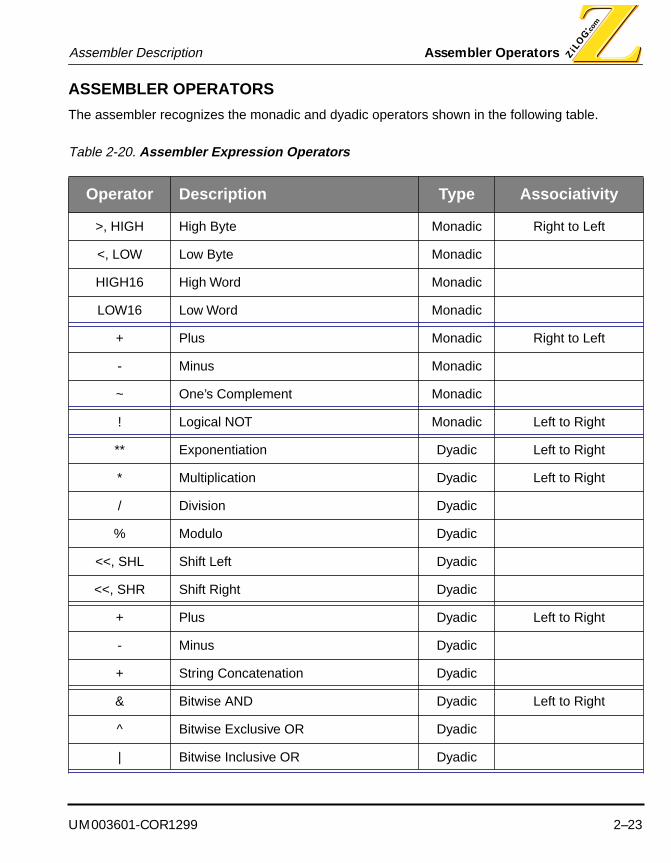
ASSEMBLER OPERATORS
The assembler recognizes the monadic and dyadic operators shown in the following table.
Table 2-20. Assembler Expression Operators
Operator Description Type Associativity
>, HIGH High Byte Monadic Right to Left
<, LOW Low Byte Monadic
HIGH16 High Word Monadic
LOW16 Low Word Monadic
+ Plus Monadic Right to Left
- Minus Monadic
~ One’s Complement Monadic
! Logical NOT Monadic Left to Right
** Exponentiation Dyadic Left to Right
* Multiplication Dyadic Left to Right
/ Division Dyadic
% Modulo Dyadic
<<, SHL Shift Left Dyadic
<<, SHR Shift Right Dyadic
+ Plus Dyadic Left to Right
- Minus Dyadic
+ String Concatenation Dyadic
& Bitwise AND Dyadic Left to Right
^ Bitwise Exclusive OR Dyadic
| Bitwise Inclusive OR Dyadic

Assembler Operators Assembler Description
2–24 UM003601-COR1299
NOTES:
1. Operators are listed in the table in order or precedence: operators nearer the top of thetable are applied before those lower in the table. Operators with the same precedence areshown in groups delimited by double horizontal rules.
2. Within a group, the order of evaluation is controlled by the operator’s associativity.Operators whose associativity is left to right are applied from left to right within the sameprecedence group. Operators whose associativity is right to left are applied from right to leftwithin the same precedence group.
3. An operator is either monadic or dyadic. Monadic operators operate on a single operand,and the operator prefixes the operand (prefix notation). Dyadic operators operate on twooperands, and the operator separates the operands (infix notation).
4. Parentheses may be used to force a particular order of evaluation, independent of operatorprecedence and associativity. Parentheses have a higher precedence that any operator.
= Equal Dyadic Left to Right
!= Not Equal Dyadic
= Strings Equal Dyadic
!= Strings Not Equal Dyadic
< Less Than Dyadic
> Greater Than Dyadic
<= Less Than or Equal Dyadic
>= Greater Than or Equal Dyadic
&& Logical AND Dyadic
|| Logical Inclusive OR Dyadic
^^ Logical Exclusive OR Dyadic
== Logical Equivalence Dyadic
Table 2-20. Assembler Expression Operators
Operator Description Type Associativity

UM003601-COR1299 2–25
Assembler Description Assembler Expressions
ASSEMBLER EXPRESSIONS
An expression is a constant, a symbol, or a combination of constants, symbols and operators. The assembler evaluates each expression into a single value, then uses that value as an operand. Ex-pression have a type attribute as well as a value. The assembler supports the following types of expression:
■ Absolute Expressions
■ Relocatable Expressions
■ Floating Point Expressions
■ String Expressions
■ Logical Expressions
■ Conditional Expressions

Assembler Expressions Assembler Description
2–26 UM003601-COR1299
The type of an expression depends on the type of its operands. Expression types are important for two reasons:
1. Some assembler directives require expressions of a particular type.
2. Only certain types of operators are allowed in certain types of expressions.
Assembler Absolute Expressions
An absolute expression is an expression with an integral value that can be completely determined by the assembler at assembly time. Thus, an absolute expression is independent of any possible control section relocation that occurs at link time.
The following operators are supported for absolute expressions: +, -, *, /, %, <<, >>, &, |, ^, ~
Assembler Relocatable Expressions
A relocatable expression is an expression with an integral value that cannot be completely resolved at assembly time. Thus, the value of a relocatable expression is dependent on possible control sec-tion relocation that occurs at link time.
Relocatable Expression
A relocatable expression is one of the following:
■ A label in a relocatable control section.
■ A symbol set to a relocatable expression, using the EQU or SET assembler directive.
External Expression
An external expression is one of the following:
■ A label defined using the EXTERN assembler directive.
■ A symbol set to an external expression, using the EQU or SET assembler directive.

UM003601-COR1299 2–27
Assembler Description Assembler Expressions
The assembler supports the arithmetic operations of addition and subtraction applied to relocatable expressions, absolute expressions or external expressions, in certain combinations. The legal com-binations are summarized in the following table.
Assembler Floating-Point Expressions
A floating point expression is an expression with a floating point value that can be completely de-termined by the assembler at assembly time. Thus, a floating point expression is independent of any possible control section relocation that occurs at link time.
A floating point expression is one of the following:
a. A floating point constant.
b. A symbol set to a floating point expression, using the EQU or SET assembler directive.
c. An expression involving floating point expressions: *, /, +, and - operators.
Assembler String Expressions
A string expression is an expression with a string value that can be completely determined by the assembler at assembly time. Thus, a string expression is independent of any possible control sec-tion relocation that occurs at link time.
Table 2-21. Types of Expressions
Type of Expression AType of Expression
BA+B A-B
absolute absolute absolute absolute
absolute external external illegal
absolute relocatable relocatable illegal
external absolute external external
external external illegal illegal
external relocatable relocatable illegal
relocatable absolute relocatable relocatable
relocatable external illegal illegal
relocatable relocatable illegal absolute

Assembler Expressions Assembler Description
2–28 UM003601-COR1299
A string expression is one of the following:
a. A string constant.
b. A symbol set to a string expression, using the EQU or SET assembler directive.
c. An expression involving string expressions and the additive (+) that concatenates two strings.
d. The following operators are supported for string expressions: =, ==, >, <, >=, >=, <=, !=.
Assembler Logical Expressions
A logical expression is an expression that tests the relationship of one expression to another at as-sembly time. The result of a logical expression is a Boolean value: true (non-zero) if the specified relationship holds between the expressions; false (zero) if the relationship does not hold. Logical expressions are used in the conditional assembly test directives.
A logical expression is one of the following:
a. A symbol set to a logical expression, using the EQU or SET assembler directive.
b. An absolute expression.
c. An expression involving absolute expressions and the relational operators. Relationaloperators are ==, !=, <, >, <=, and >=.
d. An expression involving string expressions and the relational operators.
e. An expression involving logical expressions and the logical operators. The logical operators are!, &&, ||, ^^, and =.
Assembler Conditional Expressions
A conditional expression is an expression that tests the relationship of one expression to another at execution time, and executes code sequences based on the result of the test. Conditional ex-pressions are used in the structured assembly test directives.
The conditional expressions are evaluated at execution-time, not at assembly-time. This imposes some restrictions on the format of conditional expressions, for the assembler makes use of the com-parison and branching instructions available in the target microcontroller's machine instruction set.
A conditional expression is one of the following:
a. An expression of the form condition, where condition is the name of a condition code.
b. An expression of the form lExpression <operator> rExpression, where lExpression andrExpression are absolute or relocatable expressions in an addressing mode valid for use as the

UM003601-COR1299 2–29
Assembler Description Assembler Expressions
right-hand and left-hand operands for the compare machine instruction, respectively, and<operator> is a conditional operator. The conditional operators are ==, !=, <, >, <=, and >=.
c. An expression of the form lExpression <operator> rExpression, where lExpression andrExpression are conditional expressions, and <operator> is a logical operator. The logicaloperators are &&, and ||.

Assembler Expressions Assembler Description
2–30 UM003601-COR1299
Structured AssemblyStructured assembly supports execution-time selection of sequences of source statements based on execution-time conditions. The structured assembly directives test for a specified condition and execute a block of statements only if the condition is true.
NOTE: There is no structured assembly support for the Z89C25/50 MCU core.
The structured assembly directives, when used in conjunction with the ability to assembly and link modules independently, facilitate structured programming in assembly language. It can be difficult to assimilate the logical structure of a traditional, non-structured assembly language program. Structured assembly language programs are generally easier to read and understand than non-structured programs. They may also be easier to debug and change.
The assembler directives associated with structured assembly are summarized in the following ta-ble.
The assembler directives shown in the preceding table are known collectively as structured assem-bly test directives, and are always used together to form a homogeneous structured assembly block. The assembler supports one decision structure (.$IF) and two looping structures (.$WHILE and .$REPEAT).
The assembler supports a decision structure with the .$IF, .$ELSEIF, .$ELSE, and .$ENDIF direc-tives. These directives generate code to test one or more execution-time conditions, and execute a block of statements based on the result of the tests.
Table 2-22. Assembler Directives for Structured Assembly
Assembler Directive Description
.$IF, .$REPEAT, .$WHILE Structured assembly test primary
.$ELSEIF Structured assembly test alternate
.$ELSE Structured assembly test default
.$BREAK, .$CONTINUE Structured assembly test control
.$ENDIF, .$UNTIL, .$WEND Structured assembly test end

UM003601-COR1299 2–31
Assembler Description Assembler Expressions
For example, for the decision structure:
NOTE: The examples shown in this “Structured Assembly” section use Z89C00 syntax.
the assembler generates the following code:
The assembler supports two types of looping structure with the .$WHILE, .$WEND, and .$RE-PEAT, .$UNTIL directive pairs. The .$WHILE directive generates code to test an execution-time condition, and execute a block of statements while the condition is true. Since the test is performed before executing the block, the block may not be executed.
For example, for the looping structure:
.$if (a == #0)ld a,x
.$elseld a,y
.$endif
.$if (a == #0)* cp a,#0* jp ne,$L000001
ld a,x.$else
* jp $L000002* $L000001:
ld a,y.$endif
* $L000002:
.$while (a != #0)ld x,@d0:0sub a,#1
.$wend

Assembler Expressions Assembler Description
2–32 UM003601-COR1299
the assembler generates the following code:
.$while (a != #0)* $L000001:* cp a,#0* jp eq,$L000002
ld x,@d0:0sub a,#1
* jp $L000001.$wend
* $L000002:
UM003601-COR1299 2–33
Assembler Description Assembler Expressions
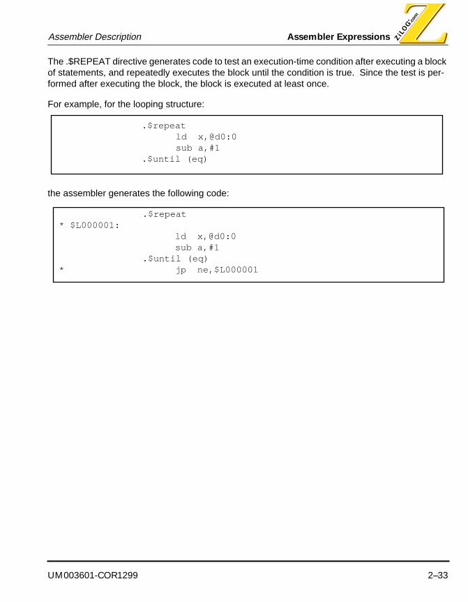
The .$REPEAT directive generates code to test an execution-time condition after executing a block of statements, and repeatedly executes the block until the condition is true. Since the test is per-formed after executing the block, the block is executed at least once.
For example, for the looping structure:
the assembler generates the following code:
.$repeatld x,@d0:0sub a,#1
.$until (eq)
.$repeat* $L000001:
ld x,@d0:0sub a,#1
.$until (eq)* jp ne,$L000001

Assembler Expressions Assembler Description
2–34 UM003601-COR1299
Structured Assembly Inputs
This section describes the structured assembly input requirements.
IF Structured Assembly Block Inputs
The .$IF, .$ELSEIF, .$ELSE and .$ENDIF assembler directives are used to test execution-timeconditions, and conditionally execute object code based on the results of the test.
Syntax
.$IF condition1 [; comment]
statements
[ .$ELSEIF condition2 [; comment ] ]
[ statements ]
.
.
.
[ .$ELSE [; comment ] ]
[ statements ]
.$ENDIF [; comment ]
UM003601-COR1299 2–35
Assembler Description Assembler Expressions
The following qualifications elaborate the syntax and semantics of the structured assembly test di-rectives. Unless otherwise specified, violations of these qualifications cause the assembly to fail.
1. The .$IF, .$ELSEIF, .$ELSE, and .$ENDIF assembler directives must be specified in that order.
2. The .$ELSEIF assembler directive is optional. It may be specified an arbitrary number of timesbetween the .$IF and .$ENDIF assembler directives.
3. The .$ELSE assembler directive is optional. It may be specified at most once between the .$IFand .$ENDIF directives.
4. If used, the .$ELSE assembler directive must be coded after any .$ELSEIF directives.
5. Any valid assembler statement may appear in the statements sections of the structuredassembly test directives. This means, among other things, that structured assembly testdirectives may be nested. The structured assembly test directives may be nested up to 255levels.
6. Nested .$ELSEIF and .$ELSE directives are associated with the most recent .$IF directive.
7. There is no preset limit on the number of statements that may appear in the statementssections; there may be any number of assembler statements in each statements section,including zero. The operating system file system may impose limitations on file sizes, and theuser should consult the appropriate operating system users guide for such limitations.
8. Each expression must be a conditional expression. See “Assembler Expressions”.
9. The .$IF and .$ENDIF directives must be coded in matching pairs. That is, it is not legal to codean .$IF directive without a matching .$ENDIF directive appearing later in the source module;nor is it legal to code an .$ENDIF directive without a matching .$IF directive appearing earlierin the source module.
10. The .$ELSEIF and .$ELSE assembler directives can only appear between enclosing .$IF and.$ENDIF directives. It is not valid for the .$ELSEIF and .$ELSE directives to appear in any othercontext.
11. The .$ELSE directive does not have any parameters.
12. The .$ENDIF directive does not have any parameters.
13. None of the .$IF, .$ELSEIF, .$ELSE, and .$ENDIF assembler directives may be labeled. If alabel is specified, a warning message is issued, and the label is discarded.
REPEAT Structured Assembly Block Inputs
The .$REPEAT, .$BREAK, .$CONTINUE and .$UNTIL assembler directives are used to test exe-cution-time conditions, and conditionally execute object code based on the results of the test.

Assembler Expressions Assembler Description
2–36 UM003601-COR1299
Syntax
.$REPEAT [; comment]
statements
[ .$BREAK [ .$IF condition2 ] [; comment ] ]
[ statements ]
[ .$CONTINUE [ .$IF condition3 ] [; comment ] ]
[ statements ]
.$UNTIL condition1 [; comment ]
The following qualifications elaborate the syntax and semantics of the structured assembly test di-rectives. Unless otherwise specified, violations of these qualifications cause the assembly to fail.
1. The .$REPEAT and .$UNTIL assembler directives must be specified in that order.
2. The .$BREAK assembler directive is optional. It may be specified an arbitrary number of timesbetween the .$REPEAT and .$UNTIL assembler directives.
3. The .$CONTINUE assembler directive is optional. It may be specified an arbitrary number oftimes between the .$REPEAT and .$UNTIL directives.
4. Any valid assembler statement may appear in the statements sections of the structuredassembly test directives. This means, among other things, that structured assembly testdirectives may be nested. The structured assembly test directives may be nested up to 255levels.
5. Nested .$BREAK and .$CONTINUE directives are associated with the most recent .$REPEATdirective.
6. There is no preset limit on the number of statements that may appear in the statementssections; there may be any number of assembler statements in each statements section,including zero. The operating system file system may impose limitations on file sizes, and theuser should consult the appropriate operating system users guide for such limitations.
7. The .$REPEAT and .$UNTIL directives must be coded in matching pairs. That is, it is not legalto code a .$REPEAT directive without a matching .$UNTIL directive appearing later in thesource module; nor is it legal to code an .$UNTIL directive without a matching .$REPEATdirective appearing earlier in the source module.
UM003601-COR1299 2–37
Assembler Description Assembler Expressions
8. The .$BREAK and .$CONTINUE assembler directives can only appear between enclosing.$REPEAT and .$UNTIL directives (or between .$WHILE and .$WEND directives). It is not validfor the .$BREAK and .$CONTINUE directives to appear in any other context.
9. The .$BREAK directive has an optional .$IF conditional parameter.
10. The .$CONTINUE directive has an optional .$IF conditional parameter.
11. None of the .$REPEAT, .$BREAK, .$CONTINUE, and .$UNTIL assembler directives may belabeled. If a label is specified, a warning message is issued, and the label is discarded.
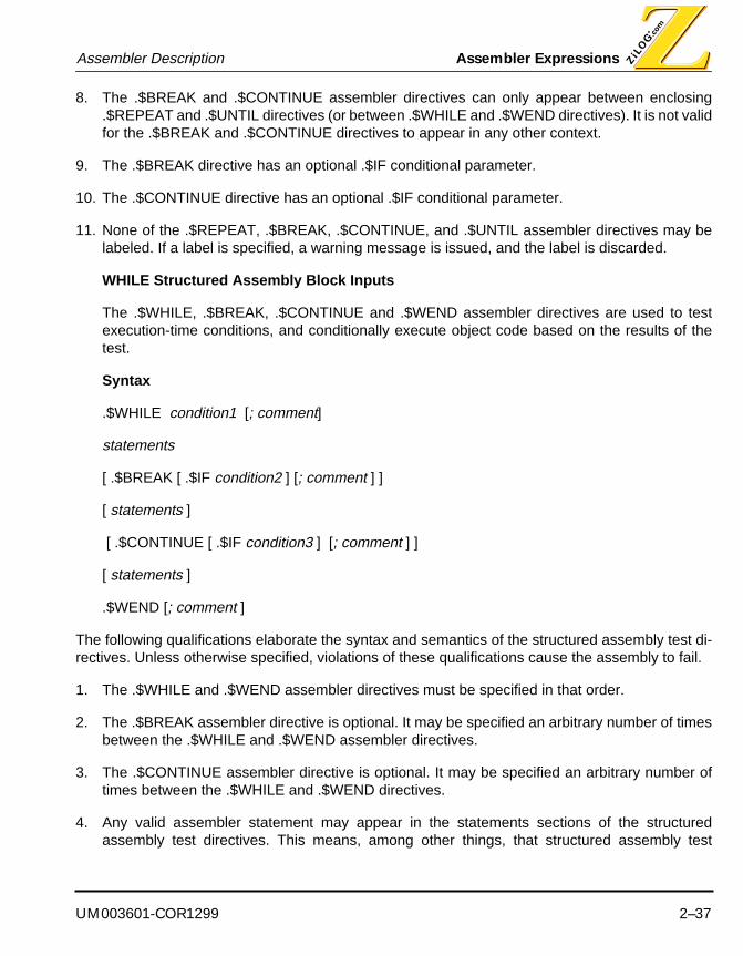
WHILE Structured Assembly Block Inputs
The .$WHILE, .$BREAK, .$CONTINUE and .$WEND assembler directives are used to testexecution-time conditions, and conditionally execute object code based on the results of thetest.
Syntax
.$WHILE condition1 [; comment]
statements
[ .$BREAK [ .$IF condition2 ] [; comment ] ]
[ statements ]
[ .$CONTINUE [ .$IF condition3 ] [; comment ] ]
[ statements ]
.$WEND [; comment ]
The following qualifications elaborate the syntax and semantics of the structured assembly test di-rectives. Unless otherwise specified, violations of these qualifications cause the assembly to fail.
1. The .$WHILE and .$WEND assembler directives must be specified in that order.
2. The .$BREAK assembler directive is optional. It may be specified an arbitrary number of timesbetween the .$WHILE and .$WEND assembler directives.
3. The .$CONTINUE assembler directive is optional. It may be specified an arbitrary number oftimes between the .$WHILE and .$WEND directives.
4. Any valid assembler statement may appear in the statements sections of the structuredassembly test directives. This means, among other things, that structured assembly test

Assembler Expressions Assembler Description
2–38 UM003601-COR1299
directives may be nested. The structured assembly test directives may be nested up to 255levels.
5. Nested .$BREAK and .$CONTINUE directives are associated with the most recent .$WHILEdirective.
6. There is no preset limit on the number of statements that may appear in the statementssections; there may be any number of assembler statements in each statements section,including zero. The operating system file system may impose limitations on file sizes, and theuser should consult the appropriate operating system users guide for such limitations.
7. The .$WHILE and .$WEND directives must be coded in matching pairs. That is, it is not legalto code a .$WHILE directive without a matching .$WEND directive appearing later in the sourcemodule; nor is it legal to code an .$WEND directive without a matching .$WHILE directiveappearing earlier in the source module.
8. The .$BREAK and .$CONTINUE assembler directives can only appear between enclosing.$WHILE and .$WEND directives (or between .$REPEAT and .$UNTIL directives). It is not validfor the .$BREAK and .$CONTINUE directives to appear in any other context.
9. The .$BREAK directive has an optional .$IF conditional parameter.
10. The .$CONTINUE directive has an optional .$IF conditional parameter.
11. None of the .$WHILE, .$BREAK, .$CONTINUE, and .$WEND assembler directives may belabeled. If a label is specified, a warning message is issued, and the label is discarded.

UM003601-COR1299 2–39
Assembler Description Assembler Expressions
Structured Assembly ProcessingThis section describes the assembly-time processing of structured assembly directives.
Validity Checks
The following validity checks are performed on the structured assembly block input data. Unless otherwise specified, violations cause the assembly to fail.
1. The syntax of the structured assembly block must conform to the requirements specified in“Structured Assembly Inputs”.
2. The .$IF and .$ENDIF directives must be properly balanced, i.e., there must be exactly one.$ENDIF directive for each .$IF directive, and the .$IF directive must precede its corresponding.$ENDIF directive.
3. The .$REPEAT and .$UNTIL directives must be properly balanced, i.e., there must be exactlyone .$UNTIL directive for each .$REPEAT directive, and the .$REPEAT directive must precedeits corresponding .$UNTIL directive.
4. The .$WHILE and .$WEND directives must be properly balanced, i.e., there must be exactlyone .$WEND directive for each .$WHILE directive, and the .$WHILE directive must precede itscorresponding .$WEND directive.
5. The structured assembly block must be completely specified with a single assembly unit. Anassembly unit is a single source file, or a single macro definition.
Sequence of Operations
The following sequences of operations are performed in processing structured assembly test direc-tives.
.$IF Sequence of Operations
The following sequence of operations is performed in processing the .$IF structured assemblytest directives.
1. The assembler generates object code to evaluate the conditions specified on the .$IFdirective and on any optional .$ELSEIF directives. If the condition is true at execution time,the object code generated from the statements associated with the .$IF directive areexecuted.
2. If the condition specified on the .$IF directive is false at execution-time, the assembler-generated object code successively evaluates the conditions specified on the .$ELSEIFdirectives, if there are any, until a true condition is evaluated. On evaluating a true.$ELSEIF condition, the object code generated from the statements associated with the.$ELSEIF directive are executed.

Assembler Expressions Assembler Description
2–40 UM003601-COR1299
3. If all conditions on the .$IF and .$ELSEIF directives are false at execution-time, and an.$ELSE directive is present, the object code generated from the statements associated withthe .$ELSE directive are executed.
4. If no tested condition is true, and if no .$ELSE directive is specified, no statements in thestructured assembly block are executed.
.$REPEAT Sequence of Operations
The following sequence of operations is performed in processing the .$REPEAT structuredassembly test directives.
1. The assembler generates object code to evaluate the conditions specified on the .$UNTILdirective and on any optional .$BREAK and .$CONTINUE directives.
2. At execution-time, the object code generated from statements in the structured assemblyblock are executed until the specified condition is true.
3. At execution time, object code generated from .$BREAK directives is executed at the pointwhere it appears in the block. If no condition is specified on the .$BREAK condition, or ifthe condition is true, the .$REPEAT loop is exited.
4. At execution time, object code generated from .$CONTINUE directives is executed at thepoint where it appears in the block. If no condition is specified on the .$CONTINUEcondition, or if the condition is true, execution of code generated from statements in theblock resumes at the beginning of the block.
.$WHILE Sequence of Operations
The following sequence of operations is performed in processing the .$WHILE structuredassembly test directives.
1. The assembler generates object code to evaluate the conditions specified on the .$WHILEdirective and on any optional .$BREAK and .$CONTINUE directives.
2. At execution-time, the object code generated from statements in the structured assemblyblock are executed while the specified condition is true.
3. At execution time, object code generated from .$BREAK directives is executed at the pointwhere it appears in the block. If no condition is specified on the .$BREAK condition, or ifthe condition is true, the .$WHILE loop is exited.
4. At execution time, object code generated from .$CONTINUE directives is executed at thepoint where it appears in the block. If no condition is specified on the .$CONTINUEcondition, or if the condition is true, execution of code generated from statements in theblock resumes at the beginning of the block.
UM003601-COR1299 2–41
Assembler Description Structured Assembly Outputs
STRUCTURED ASSEMBLY OUTPUTS
Outputs from structured assembly is the object code generated from source statements in the struc-tured assembly block, as well as assembler-generated object code to evaluate the conditionals of the structured assembly directives. The assembler-generated directives may appear in the listing file. The generated object code appears in the object module.
If any errors are detected during structured assembly processing, then error messages are gener-ated. Error messages are written to the messages file, and to the listing file, if one is being pro-duced.
CONDITIONAL ASSEMBLY
This section describes the conditional assembly capabilities of the ZMASM cross assembler.
Conditional assembly supports assembly-time selection of sequences of source statements based on assembly-time conditions. The conditional assembly directives test for a specified condition and assemble a block of statements only if the condition is true. While conditional assembly directives can be used in open code, they are most useful when used in conjunction with the macro processor, to vary the sequence of statements generated during macro expansion. In particular, two capabili-ties that are dependent on conditional assembly greatly enhance the usefulness of macros:
■ Conditional assembly directives can be used to validate the macro call actual parameters.
■ The statements generated as a result of macro expansion can be conditioned on the values of themacro parameters.

Conditional Assembly Inputs Assembler Description
2–42 UM003601-COR1299
The assembler directives associated with conditional assembly are summarized in the following ta-ble.
The IF, IFDEF/IFNDEF, IFEQ/IFEQI/IFNEQ/IFNEQI, IFB/IFNB, ELSEIF, ELSE and ENDIF condi-tional assembly directives are known collectively as conditional assembly test directives, and are always used together to form a homogeneous conditional assembly block. Symbols defined with the SET assembler directive are known as variable symbols. The SET directive can be used inde-pendently of the conditional assembly test directives, although it is usually most powerful when used in conjunction with the other conditional assembly directives.
CONDITIONAL ASSEMBLY INPUTS
The input elements of conditional assembly are:
■ Symbols and expressions, and their attributes.
■ Assembler directives for conditional assembly.
The general format of conditional assembly inputs is illustrated in the following figure.
Table 2-23. Assembler Directives for Conditional Assembly
Assembler Description
IF, IFDEF, IFNDEF, IFEQ, IFEQI, IFNEQ, IFNEQI, IFB, IFNB
Conditional assembly test primary
ELSEIF Conditional assembly test alternate
ELSE Conditional assembly test default
ENDIF Conditional assembly test end
SET Assign a value to a symbol

UM003601-COR1299 2–43
Assembler Description Conditional Assembly Inputs
Figure 2-3. General Format of Conditional Inputs
. . .set. . .
Optional SET Symbols
. . .if. . .
Primary Test
. . .statements. . .
. . .elseif. . .
Optional Alternate Test(May be repeated)
. . .statements. . .
. . .else. . .
Optional Test Default
. . .statements. . .
. . .endif. . .
End of Conditional Test

Conditional Assembly Inputs Assembler Description
2–44 UM003601-COR1299
Conditional Assembly Variable Inputs
The SET assembler directive is used to assign an expression value and type to a symbol. The sym-bol can then be used throughout the remainder of the source module. In particular, it can be used with the conditional assembly test directives, to vary the sequence of statements assembled.
Name SET Expression
Syntax
The following qualifications elaborate the syntax and semantics of the conditional assembly setdirective. Unless otherwise specified, violations of these qualifications cause the assembly tofail.
1. The Name is the symbolic name of the Expression. Name must be a valid symbol. See“Assembler Symbols” section.
2. The Name may be the same as that used on a previous SET directive. That is, variablesymbols may be redefined.
3. The Name may not be the same as any symbol except a symbol defined with a previousSET directive.
4. The Expression must be an absolute, string, or floating point expression. See “AssemblerExpressions” section.
Conditional Assembly Block Inputs
IF Conditional Assembly Block Inputs
The IF, ELSEIF, ELSE and ENDIF assembler directives are used to test assembly-timeconditions, and conditionally assemble source statements based on the results of the test.

UM003601-COR1299 2–45
Assembler Description Conditional Assembly Inputs
Syntax
IF expression [; comment]
statements
[ ELSEIF expression [; comment ] ]
[ statements ]
.
.
.
[ ELSE [; comment ] ]
[ statements ]
ENDIF [; comment ]
The following qualifications elaborate the syntax and semantics of the conditional assembly testdirectives. Unless otherwise specified, violations of these qualifications cause the assembly tofail.
1. The IF, ELSEIF, ELSE, and ENDIF assembler directives must be specified in that order.
2. The ELSEIF assembler directive is optional. It may be specified an arbitrary number oftimes between the IF and ENDIF assembler directives.
3. The ELSE assembler directive is optional. It may be specified at most once between the IFand ENDIF directives.
4. If used, the ELSE assembler directive must be coded after any ELSEIF directives.
5. Any valid assembler statement may appear in the statements sections of the conditionalassembly test directives. This means, among other things, that conditional assembly testdirectives may be nested. The conditional assembly test directives may be nested up to 255levels.
6. Nested ELSEIF and ELSE directives are associated with the most recent IF directive.
7. There is no preset limit on the number of statements that may appear in the statementssections; there may be any number of assembler statements in each statements section,including zero. The operating system file system may impose limitations on file sizes, andthe user should consult the appropriate operating system users guide for such limitations.

Conditional Assembly Inputs Assembler Description
2–46 UM003601-COR1299
8. Each expression must be a logical expression. See “Assembler Expressions”.
9. The IF and ENDIF directives must be coded in matching pairs. That is, it is not legal to codean IF directive without a matching ENDIF directive appearing later in the source module;nor is it legal to code an ENDIF directive without a matching IF directive appearing earlierin the source module.
10. The ELSEIF and ELSE assembler directives can only appear between enclosing IF andENDIF directives. It is not valid for the ELSEIF and ELSE directives to appear in any othercontext.
11. The ELSE directive does not have any parameters.
12. The ENDIF directive does not have any parameters.
13. None of the IF, ELSEIF, ELSE, and ENDIF assembler directives may be labeled. If a labelis specified, a warning message is issued, and the label is discarded.
IFDEF/IFNDEF Conditional Assembly Block Inputs
The IFDEF and ENDIF assembler directives are used to test assembly-time conditions, andconditionally assemble source statements based on the results of the test.
Syntax
IF[N]DEF label [; comment]
statements
[ ELSE [; comment ] ]
[ statements ]
ENDIF [; comment ]
The following qualifications elaborate the syntax and semantics of the conditional assembly testdirectives. Unless otherwise specified, violations of these qualifications cause the assembly tofail.
1. The IF[N]DEF, ELSE, and ENDIF assembler directives must be specified in that order.
2. The ELSE assembler directive is optional. It may be specified at most once between theIF[N]DEF and ENDIF directives.
3. Any valid assembler statement may appear in the statements sections of the conditionalassembly test directives. This means, among other things, that conditional assembly test

UM003601-COR1299 2–47
Assembler Description Conditional Assembly Inputs
directives may be nested. The conditional assembly test directives may be nested up to 255levels.
4. Nested ELSE directives are associated with the most recent IF[N]DEF directive.
5. There is no preset limit on the number of statements that may appear in the statementssections; there may be any number of assembler statements in each statements section,including zero. The operating system file system may impose limitations on file sizes, andthe user should consult the appropriate operating system users guide for such limitations.
6. Each label must be a valid assembler symbol. See “Assembler Symbols”.
7. The IF[N]DEF and ENDIF directives must be coded in matching pairs. That is, it is not legalto code an IF[N]DEF directive without a matching ENDIF directive appearing later in thesource module; nor is it legal to code an ENDIF directive without a matching IF[N]DEFdirective appearing earlier in the source module.
8. The ELSE directive does not have any parameters.
9. The ENDIF directive does not have any parameters.
10. None of the IF[N]DEF, ELSE, and ENDIF assembler directives may be labeled. If a label isspecified, a warning message is issued, and the label is discarded.
IFEQ/IFEQI/IFNEQ/IFNEQI Conditional Assembly Block Inputs
The IFEQ[I], ELSE and ENDIF assembler directives are used to test assembly-time conditions,and conditionally assemble source statements based on the results of the test.
Syntax
IF[N]EQ[I] argument1 , argument2 [; comment]
statements
[ ELSE [; comment ] ]
[ statements ]
ENDIF [; comment ]
The following qualifications elaborate the syntax and semantics of the conditional assembly testdirectives. Unless otherwise specified, violations of these qualifications cause the assembly tofail.
1. The IF[N]EQ[I], ELSE, and ENDIF assembler directives must be specified in that order.
Conditional Assembly Inputs Assembler Description
2–48 UM003601-COR1299
2. The ELSE assembler directive is optional. It may be specified at most once between theIF[N]EQ[I] and ENDIF directives.
3. Any valid assembler statement may appear in the statements sections of the conditionalassembly test directives. This means, among other things, that conditional assembly testdirectives may be nested. The conditional assembly test directives may be nested up to255 levels.
4. Nested ELSE directives are associated with the most recent IF[N]EQ[I] directive.
5. There is no preset limit on the number of statements that may appear in the statementssections; there may be any number of assembler statements in each statements section,including zero. The operating system file system may impose limitations on file sizes, andthe user should consult the appropriate operating system users guide for such limitations.
6. Each argument1 and argument2 must be a valid assembler string expression or macroformal parameter name. See “String Expressions” and “Macro Definition Inputs”.
7. The IF[N]EQ[I] and ENDIF directives must be coded in matching pairs. That is, it is not legalto code an IF[N]EQ[I] directive without a matching ENDIF directive appearing later in thesource module; nor is it legal to code an ENDIF directive without a matching IF[N]EQ[I]directive appearing earlier in the source module.
8. The ELSE directive does not have any parameters.
9. The ENDIF directive does not have any parameters.
10. None of the IF[N]EQ[I], ELSE, and ENDIF assembler directives may be labeled. If a labelis specified, a warning message is issued, and the label is discarded.
IFB/IFNB Conditional Assembly Block Inputs
The IF[N]B, ELSE and ENDIF assembler directives are used to test assembly-time conditions,and conditionally assemble source statements based on the results of the test.
UM003601-COR1299 2–49
Assembler Description Conditional Assembly Inputs
Syntax
IF[N]B fParameter [; comment]
statements
[ ELSE [; comment ] ]
[ statements ]
ENDIF [; comment ]
The following qualifications elaborate the syntax and semantics of the conditional assembly testdirectives. Unless otherwise specified, violations of these qualifications cause the assembly tofail.
1. The IF[N]B, ELSE, and ENDIF assembler directives must be specified in that order.
2. The ELSE assembler directive is optional. It may be specified at most once between theIF[N]B and ENDIF directives.
3. Any valid assembler statement may appear in the statements sections of the conditionalassembly test directives. This means, among other things, that conditional assembly testdirectives may be nested. The conditional assembly test directives may be nested up to255 levels.
4. Nested ELSE directives are associated with the most recent IF[N]B directive.
5. There is no preset limit on the number of statements that may appear in the statementssections; there may be any number of assembler statements in each statements section,including zero. The operating system file system may impose limitations on file sizes, andthe user should consult the appropriate operating system users guide for such limitations.
6. Each fParameter must be a macro definition formal parameter name. See “Macro DefinitionInputs”.
7. The IF[N]B and ENDIF directives must be coded in matching pairs. That is, it is not legal tocode an IF[N]B directive without a matching ENDIF directive appearing later in the sourcemodule; nor is it legal to code an ENDIF directive without a matching IF[N]B directiveappearing earlier in the source module.
8. The ELSE directive does not have any parameters.
9. The ENDIF directive does not have any parameters.
10. None of the IF[N]B, ELSE, and ENDIF assembler directives may be labeled. If a label isspecified, a warning message is issued, and the label is discarded.

Conditional Assembly Processing Assembler Description
2–50 UM003601-COR1299
CONDITIONAL ASSEMBLY PROCESSING
This section describes the assembly-time processing of conditional assembly directives. The SET directive processing is described in “Conditional Assembly Set Processing”. The IF, ELSEIF, ELSE, and ENDIF assembler directives are treated together, and their processing is described in “Condi-tional Assembly Block Processing”.
Conditional Assembly Variable Processing
This section describes the processing of the SET assembler directive.
Validity Checks
The following validity checks are performed on the conditional assembly SET directive inputdata. Unless otherwise specified, violations cause the assembly to fail.
1. The syntax of the conditional assembly block must conform to the requirements specifiedin “Conditional Assembly Inputs”.
2. The SET directive Name may not be referenced before it is defined.
Sequence of Operations
The following sequence of operations is performed in processing the conditional assembly SETdirective, and to the references to defined variable symbols.
1. The assembler creates a symbol table node for the variable symbol Name, if the Name wasnot previously defined.
2. The variable symbol Expression is evaluated, and the Expression value and type arerecorded with the symbol Name in the symbol table.
3. Subsequent references to Name in the source module operand field are replaced with thevalue of the Expression specified on the SET directive. See “Assembler SourceStatements” for a description of source statement fields.
4. If a variable symbol Name is referenced before it is first defined, the assembler flags anerror. That is, it is not legal to forward reference a variable symbol.
5. References to a defined variable symbol refer to the most recent definition.
Conditional Assembly Block Processing
This section describes the processing of statements in a conditional assembly block.
UM003601-COR1299 2–51
Assembler Description Conditional Assembly Processing
Validity Checks
The following validity checks are performed on the conditional assembly block input data.Unless otherwise specified, violations cause the assembly to fail.
1. The syntax of the conditional assembly block must conform to the requirements specifiedin “Conditional Assembly Inputs”.
2. The IF and ENDIF directives must be properly balanced; that is, there must be exactly oneENDIF directive for each IF directive, and the IF directive must precede its correspondingENDIF directive.
3. The IF[N]DEF and ENDIF directives must be properly balanced; that is, there must beexactly one ENDIF directive for each IF[N]DEF directive, and the IF[N]DEF directive mustprecede its corresponding ENDIF directive.
4. The IF[N]EQ[I] and ENDIF directives must be properly balanced; that is, there must beexactly one ENDIF directive for each IF[N]EQ[I] directive, and the IF[N]EQ[I] directive mustprecede its corresponding ENDIF directive.
5. The IF[N]B and ENDIF directives must be properly balanced; that is, there must be exactlyone ENDIF directive for each IF[N]B directive, and the IF[N]B directive must precede itscorresponding ENDIF directive.
6. The conditional assembly block must be completely specified with a single assembly unit.An assembly unit is a single source file, or a single macro definition.
Sequence of Operations
The following sequences of operations are performed in processing conditional assembly test di-rectives.
IF Sequence of Operations
The following sequence of operations is performed in processing the IF conditional assemblytest directives.
1. The assembler evaluates the condition specified on the IF directive, and if the condition istrue, the statements associated with the IF directive are assembled.
2. If the condition specified on the IF directive is false, the assembler successively evaluatesthe conditions specified on the ELSEIF directives, if there are any, until a true condition isevaluated. On evaluating a true ELSEIF condition, the statements associated with theELSEIF directive are assembled.
3. If all conditions on the IF and ELSEIF directives are false, and an ELSE directive is present,the statements associated with the ELSE directive are assembled.

Conditional Assembly Processing Assembler Description
2–52 UM003601-COR1299
4. If no tested condition is true, and if no ELSE directive is specified, no statements in theconditional assembly block are assembled.
IFDEF Sequence of Operations
The following sequence of operations is performed in processing the IFDEF conditionalassembly test directives.
1. The assembler interrogates the symbol table for the label specified on the IFDEF directive,and if the label is defined in the table, the statements associated with the IFDEF directiveare assembled.
2. If the label on the IFDEF directive is undefined, and an ELSE directive is present, thestatements associated with the ELSE directive are assembled.
3. If the label on the IFDEF directive is undefined, and if no ELSE directive is specified, nostatements in the conditional assembly block are assembled.
IFNDEF Sequence of Operations
The following sequence of operations is performed in processing the IFNDEF conditionalassembly test directives.
1. The assembler interrogates the symbol table for the label specified on the IFNDEFdirective, and if the label is not defined in the table, the statements associated with theIFNDEF directive are assembled.
2. If the label on the IFNDEF directive is defined, and an ELSE directive is present, thestatements associated with the ELSE directive are assembled.
3. If the label on the IFDEF directive is defined, and if no ELSE directive is specified, nostatements in the conditional assembly block are assembled.
IFEQ Sequence of Operations
The following sequence of operations is performed in processing the IFEQ conditionalassembly test directives.
1. The assembler compares the string expressions specified on the IFEQ directive, and if theyare equal, the statements associated with the IFEQ directive are assembled. Two stringsare considered to be equal if they are the same length, and if each positionally matchedpair of characters has the same ASCII value.
NOTE: This comparison is case-sensitive.
2. If the strings on the IFEQ directive are different, and an ELSE directive is present, thestatements associated with the ELSE directive are assembled.

UM003601-COR1299 2–53
Assembler Description Conditional Assembly Processing
3. If the strings are not equal, and if no ELSE directive is specified, no statements in theconditional assembly block are assembled.
IFEQI Sequence of Operations
The following sequence of operations is performed in processing the IFEQI conditionalassembly test directives.
1. The assembler compares the string expressions specified on the IFEQI directive, and ifthey are equal, the statements associated with the IFEQI directive are assembled. Twostrings are considered to be equal if they are the same length, and if each positionallymatched pair of characters has the same ASCII value or represents the same alphabeticcharacter.
NOTE: This comparison is case-insensitive.
2. If the strings on the IFEQI directive are different, and an ELSE directive is present, thestatements associated with the ELSE directive are assembled.
3. If the strings are not equal, and if no ELSE directive is specified, no statements in theconditional assembly block are assembled.
IFNEQ Sequence of Operations
The following sequence of operations is performed in processing the IFNEQ conditionalassembly test directives.
1. The assembler compares the string expressions specified on the IFNEQ directive, and ifthey are not equal, the statements associated with the IFNEQ directive are assembled.Two strings are considered to be equal if they are the same length, and if each positionallymatched pair of characters has the same ASCII value.
NOTE: This comparison is case-sensitive.
2. If the strings on the IFNEQ directive are not different, and an ELSE directive is present, thestatements associated with the ELSE directive are assembled.
3. If the strings are equal, and if no ELSE directive is specified, no statements in theconditional assembly block are assembled.
IFNEQI Sequence of Operations
The following sequence of operations is performed in processing the IFNEQI conditionalassembly test directives.
1. The assembler compares the string expressions specified on the IFNEQI directive, and ifthey are not equal, the statements associated with the IFNEQI directive are assembled.

Conditional Assembly Processing Assembler Description
2–54 UM003601-COR1299
Two strings are considered to be equal if they are the same length, and if each positionallymatched pair of characters has the same ASCII value or represents the same alphabeticcharacter.
NOTE: This comparison is case-insensitive.
2. If the strings on the IFNEQI directive are not different, and an ELSE directive is present, thestatements associated with the ELSE directive are assembled.
3. If the strings are equal, and if no ELSE directive is specified, no statements in theconditional assembly block are assembled.
IFB Sequence of Operations
The following sequence of operations is performed in processing the IFB conditional assemblytest directives.
1. The assembler interrogates the symbol table for the macro formal parameter specified onthe IFB directive, and if the corresponding actual macro parameter is null, the statementsassociated with the IFB directive are assembled.
2. If the parameter named on the IFB directive is not null and an ELSE directive is present,the statements associated with the ELSE directive are assembled.
3. If the parameter is not null, and if no ELSE directive is specified, no statements in theconditional assembly block are assembled.
IFNB Sequence of Operations
The following sequence of operations is performed in processing the IFNB conditionalassembly test directives.
1. The assembler interrogates the symbol table for the macro formal parameter specified onthe IFNB directive, and if the corresponding actual macro parameter is not null, thestatements associated with the IFB directive are assembled.
2. If the parameter named on the IFB directive is null and an ELSE directive is present, thestatements associated with the ELSE directive are assembled.
3. If the parameter is null, and if no ELSE directive is specified, no statements in theconditional assembly block are assembled.

UM003601-COR1299 2–55
Assembler Description Conditional Assembly Processing
Conditional Assembly OutputsOutputs from conditional assembly are the source statements in the true conditional assembly block. The conditionally included statements may appear in the listing file. If the statements in the conditionally accepted block cause any object code to be generated, then the generated object code appears in the object module.
If any errors are detected during conditional assembly processing, then error messages are gener-ated. Error messages are written to the messages file, and to the listing file, if one is being pro-duced.
Assembler DirectivesThe assembler supports the following directives. Full descriptions of each directive follow the sum-mary table, which follows. For compatibility with other assemblers, the assembler supports the in-dicated synonyms.
Table 2-24. Assembler Directive Set Summary
Mnemonic Alias Description Page
ALIGN .ALIGN Advance The Location Counter To A Boundary 2-60
.ASCII .STRING Assemble Values Into Consecutive Memory Locations
2-62
.ASCIZ Assemble/Append Values Into Consecutive Memory Locations
2-64
.ASECT Specify The Current Control Section 2-66
.ASG Assign Character Strings To Substitution Symbols
2-67
.BES Reserve Initialized Space In Current Control Section
2-68
BFRACT Assemble Fractional Values Into Memory Locations
2-69
BLKB Reserve/Initialize Blocks of Storage 2-71
BLKL Reserve/Initialize Blocks of Storage 2-71
BLKW Reserve/Initialize Blocks of Storage 2-71

Conditional Assembly Processing Assembler Description
2–56 UM003601-COR1299
.BSS Reserve Space In .BSS 2-73
CHIP CPU Specify The Target Microcontroller 2-74
COMMENT Classify Stream Of Characters 2-75
CONDLIST Control Listing Of Conditional Assembly Blocks
2-76
.DATA Set The Current Control Section 2-62
DB .BYTE Assemble Values Into Consecutive Locations 2-78
DEFINE Name A Control Section 2-80
DL .LONG Assemble Values Into Consecutive Locations 2-78
DS Reserve Uninitialized Space 2-84
DW .INT Assemble Values Into Consecutive Locations 2-78
.WORD Assemble Values Into Consecutive Locations 2-78
ELSEIF .ELSEIF Support Conditional Assembly 3-86
ELIF Support Conditional Assembly 3-86
END .END Terminates the Assembly 2-85
ENDIF .ENDIF Support Conditional Assembly 3-86
.ENDSTRUCT Group Data Elements 2-123
EQU .EQU Equate Symbols To Expressions 2-88
ERROR .EMSG Generate Error/Warning Messages 2-90
EVAL Assign Character Strings To Substitution Symbols
2-92
EXIT Generate Error/Warning Messages 2-90
EXTERN .EXTERN Identify An External Symbol 2-93
Table 2-24. Assembler Directive Set Summary
Mnemonic Alias Description Page

UM003601-COR1299 2–57
Assembler Description Conditional Assembly Processing
.GLOBAL Identify A Defined Symbol 2-93
.REF Identify A Defined Symbol 2-93
XREF Identify A Defined Symbol 2-93
FILE .FILE Identify A Source File Name 2-94
.FLOAT Assemble Floating-Point Values 2-95
FRACT DF Assemble Fractional Values Into Memory Locations
2-69
GLOBALS Declare Symbols Globally To Linker 2-96
IF .IF Support Conditional Assembly 3-86
INCLUDE .COPY Insert Source Statement 2-97
.INCLUDE Insert Source Statement 2-97
LFRACT DD Assemble Fractional Values Into Memory Locations
2-69
LIST .LIST Control Statements To Listing File 2-99
MACCNTR Limit Macro Recursion Depth 2-100
MACEND .ENDM Place Values Into Consecutive Memory Locations
2-104
ENDMAC Place Values Into Consecutive Memory Locations
2-104
MACEXIT .MEXIT Terminate Macro Expansion 2-101
MACLIST Specify Listing File Contents 2-102
MACNOTE .MMSG Print Listing File Message 2-103
MACRO .MACRO Define A Macro 2-104
.MLIST MACLIST Control Macro Expansion Statements 2-106
Table 2-24. Assembler Directive Set Summary
Mnemonic Alias Description Page
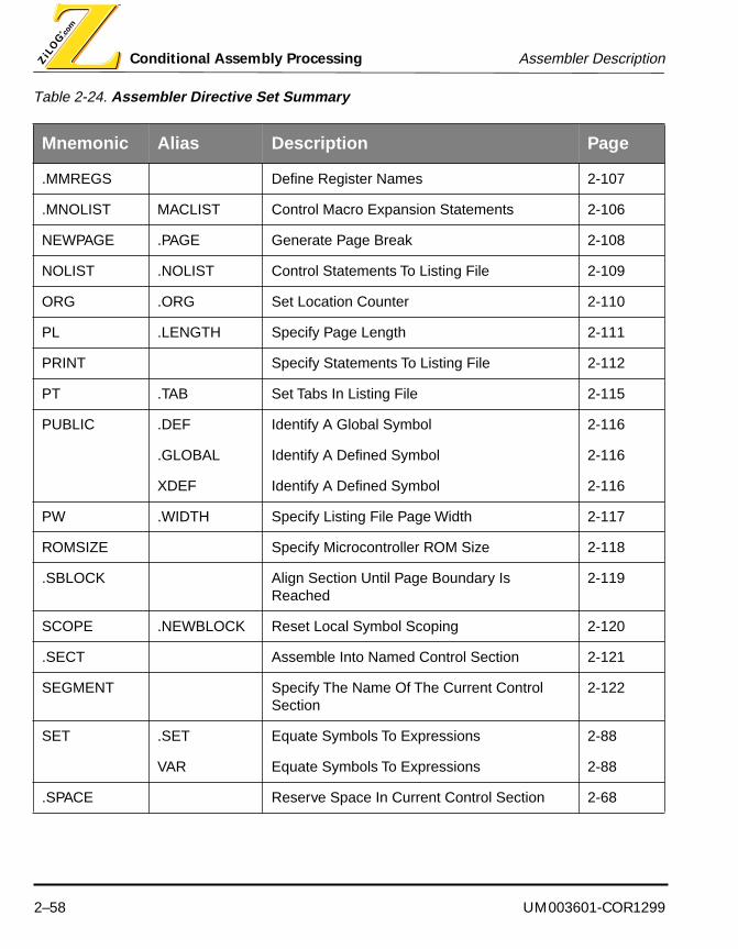
Conditional Assembly Processing Assembler Description
2–58 UM003601-COR1299
.MMREGS Define Register Names 2-107
.MNOLIST MACLIST Control Macro Expansion Statements 2-106
NEWPAGE .PAGE Generate Page Break 2-108
NOLIST .NOLIST Control Statements To Listing File 2-109
ORG .ORG Set Location Counter 2-110
PL .LENGTH Specify Page Length 2-111
PRINT Specify Statements To Listing File 2-112
PT .TAB Set Tabs In Listing File 2-115
PUBLIC .DEF Identify A Global Symbol 2-116
.GLOBAL Identify A Defined Symbol 2-116
XDEF Identify A Defined Symbol 2-116
PW .WIDTH Specify Listing File Page Width 2-117
ROMSIZE Specify Microcontroller ROM Size 2-118
.SBLOCK Align Section Until Page Boundary Is Reached
2-119
SCOPE .NEWBLOCK Reset Local Symbol Scoping 2-120
.SECT Assemble Into Named Control Section 2-121
SEGMENT Specify The Name Of The Current Control Section
2-122
SET .SET Equate Symbols To Expressions 2-88
VAR Equate Symbols To Expressions 2-88
.SPACE Reserve Space In Current Control Section 2-68
Table 2-24. Assembler Directive Set Summary
Mnemonic Alias Description Page

UM003601-COR1299 2–59
Assembler Description Conditional Assembly Processing
.STRUCT Group Data Elements 2-123
SUBTITLE Define Listing Subtitle 2-125
.TAG Group Data Elements
TARGET Specify Target Microcontroller CPU 2-126
.TEXT Make .TEXT Control Section The Current Section
2-127
TITLE .TITLE Define Listing Subtitle 2-125
.USECT Reserve Uninitialized Space 2-128
VECTOR Initialize Microcontroller Vector 2-129
WARNING Generate Error/Warning Messages 2-90
Table 2-24. Assembler Directive Set Summary
Mnemonic Alias Description Page
Conditional Assembly Processing Assembler Description
2–60 UM003601-COR1299
Purpose
The ALIGN assembler directive advances the location counter until a specified boundary isreached.
Syntax
ALIGN [expression]
Alias
.Align
Description
The ALIGN assembler directive aligns the next variable or directive on an address that is amultiple of the specified expression.
The expression operand is required, and must be an absolute integral constant expression.The assembler advances the current control section location counter to the next addressthat is evenly divisible by the value specified in expression.
Example
This example illustrates how to align the location counter on the next address that is a mul-tiple of sixteen.
ALIGN 16
Expression Is Not Specified
When there is no expression specified, the ALIGN/.ALIGN assembler directive aligns the section program counters on the next 128-byte or 128-word boundary, respectively corre-sponding to byte or word addressable MCU. The alignment purpose ensures the following code begins or a page boundary. The assembler assembles bytes or words containing NOPS up to 128-word boundary.
.ALIGN Advance The Location Counter to a Boundary .ALIGN

UM003601-COR1299 2–61
Assembler Description Conditional Assembly Processing
Example
This example shows that a section program counter is aligned on the next 128-byte bound-ary for Z8 MCU.
00000000 DS 75H
00000075 AA AAAA AA AA DB [5] 0AAH
0000007A FF FF FF FF FF* align
00000080 41 42 43 .string “ABC”
new page boundary
NOTE: Locations 7AH to 7Fh are filled with NOPS directives.
You must not use a label on this instruction.

Conditional Assembly Processing Assembler Description
2–62 UM003601-COR1299
Purpose
The .ASCII assembler directive assembles specified values into consecutive memory loca-tions.
Syntax
[ label ] .ASCII [[ repeat1 ]] initializer1 [, [[ repeat2 ]] initializer2 ] ...
Alias
.STRING
Description
The .ASCII directive places 8-bit characters from a character string into the current controlsection. For word-addressed control sections, the data is packed so that each word con-tains two 8-bit bytes. Each initializer is either:
1. An expression that the assembler evaluates and treats as an 8-bit (byte sections) or 16-bit (word sections) signed number, or
2. A character string enclosed in double quotes. Each character in a string represents aseparate 8-bit value.
For word-addressed sections, values are packed into words, starting with the most signifi-cant byte of the word. Any unused space is padded with null bytes (0s). This assemblerdirective differs from the DB directive in that DB does not pack values into words.
The assembler truncates any values that are greater than 8 bits.
You may have any number of initializers, but they must fit on a single source statement line.
Each initializer may be preceded by a repeat specification, which is an absolute numberenclosed in square brackets. The memory allocation and initialization is performed repeattimes.
If you use a label, it points to the first memory address that is initialized.
.ASCII Assemble Values Into Consecutive Memory Locations .ASCII

UM003601-COR1299 2–63
Assembler Description Conditional Assembly Processing
Examples
This example shows a simple string initialization with a label pointing to the first memoryaddress allocated.
StrLabel: .ASCII “ABCD”
This example shows a string initializer repeated one hundred times.
.ASCII [ 100 ] “X”

Conditional Assembly Processing Assembler Description
2–64 UM003601-COR1299
Purpose
The .ASCIZ assembler directive assembles specified values into consecutive memory lo-cations, appending a value of zero to each value.
Syntax
[ label ] .ASCIZ [[ repeat1 ]] initializer1 [, [[ repeat2 ]] initializer2 ] ...
Description
The .ASCIZ directive places 8-bit characters from a character string into the current controlsection. For word-addressed control sections, the data is packed so that each word con-tains two 8-bit bytes. After space is allocated for an initializer, an additional address is allo-cated and initialized to zero. Each initializer is either:
1. An expression that the assembler evaluates and treats as an 8-bit (byte sections) or 16-bit (word sections) signed number, or
2. A character string enclosed in double quotes. Each character in a string represents aseparate 8-bit value.
For word-addressed sections, values are packed into words, starting with the most signifi-cant byte of the word. Any unused space is padded with null bytes (0s). This assemblerdirective differs from the DB directive in that DB does not pack values into words.
The assembler truncates any values that are greater than 8 bits.
You may have any number of initializers, but they must fit on a single source statement line.
.ASCIZ Assemble Values Into Consecutive Memory Locations .ASCIZ
UM003601-COR1299 2–65
Assembler Description Conditional Assembly Processing
Each initializer may be preceded by a repeat specification, which is an absolute number enclosed in square brackets. The memory allocation and initialization is performed repeat times.
If you use a label, it points to the first memory address that is initialized.
Examples
This example shows a simple zero-terminated string initialization with a label pointing to thefirst memory address allocated.
StrLabel: .ASCIZ “ABCD”
This example shows a zero-terminated string initializer repeated one hundred times.
.ASCIZ [ 100 ] “X”
Conditional Assembly Processing Assembler Description
2–66 UM003601-COR1299
Purpose
The .ASECT assembler directive makes a named absolute control section the current con-trol section.
Syntax
.ASECT “section”, address
Description
The .ASECT assembler directive makes the named control section the current control sec-tion; the assembler begins assembling into the named section. The address specifies theorigin of the control section. Sections defined with the .ASECT assembler directive are ab-solute sections, and are not subject to relocation by the linker.
The section operand is required, and specifies the control section name. It must be en-closed in double quotes.
The address operand is required, and specifies the control section origin, or start address.It must be an absolute integer expression.
You must not use a label on this directive.
Example
This example illustrates how to make a named absolute section the current control section.
.ASECT “AbsSection”, 1000h
.ASECT Specify The Current Control Section .ASECT

UM003601-COR1299 2–67
Assembler Description Conditional Assembly Processing
Purpose
The .ASG assembler directive assigns character strings to substitution symbols.
Syntax
.ASG [“] character-string [“], substitution symbol
Description
The .ASG assembler directive substitutes a character string with a symbol. The quota-tion marks are optional. The substitution symbol is required and must be a valid sym-bol.
Example
.asg “EXT1”, reg1
.ASG Assign Character Strings To Substitution Symbols .ASG

Conditional Assembly Processing Assembler Description
2–68 UM003601-COR1299
Purpose
The .SPACE and .BES assembler directives reserve uninitialized space in the current con-trol section.
Syntax
[ label ] .SPACE length
[ label ] .BES length
Description
The .SPACE and .BES assembler directive reserves uninitialized space in the current con-trol section. The length specifies the number of bits to be reserved in the current section.The optional label names a symbol to be assigned the value of the first or last address re-served.
The length operand is required, and specifies the number of bits to be reserved in the cur-rent control section.
The label is optional. If the label is specified on the .SPACE directive, the label names asymbol to be assigned the value of the first address allocated by the directive in the currentcontrol section. If the label is specified on the .BES directive, the label names a symbol tobe assigned the value of the last address allocated by the directive in the current controlsection.
Example
This example illustrates how to allocate 16 bits in the current section, and assign a label tothe first address allocated.
TempVar .SPACE 16
.BES/.SPACE Reserve Uninitialized Space .BES/.SPACEIn Current Control Section

UM003601-COR1299 2–69
Assembler Description Conditional Assembly Processing
Purpose
The BFRACT, FRACT, and LFACT assembler directives assemble specified fractional val-ues into consecutive memory locations.
Syntax
[ label ] BFRACT[[ repeat1 ]] initializer1 [, [[ repeat2 ]] initializer2 ] ...
[ label ] FRACT[[ repeat1 ]] initializer1 [, [[ repeat2 ]] initializer2 ] ...
[ label ] LFRACT[[ repeat1 ]] initializer1 [, [[ repeat2 ]] initializer2 ] ...
Description
The BFRACT, FRACT and LFRACT directives place fractional values into the current con-trol section. Each initializer must be a floating point expression in the range [-1.0,1.0).
The FRACT directive places 16-bit fractional values into the current control section. TheBFRACT directive places 8-bit fractional values into the current control section. TheLFRACT directive places 32-bit fractional values into the current control section. The num-ber of addresses allocated depends upon the size of the memory of the current control sec-tion. The following table shows the number of addresses allocated per initializer.
You may have any number of initializers, but they must fit on a single source statement line,and they must be separated by commas.
Each initializer may be preceded by a repeat specification, which is an absolute numberenclosed in square brackets. The memory allocation and initialization is performed repeattimes.
Table 2-25. Number of Addresses per Initializer
Instruction 8-Bit 16-Bit 32-Bit
BFRACT 1 1 1
FRACT 2 1 1
LFRACT 4 2 1
BFRACT/FRACT / Assemble Fractional Values BFRACT/FRACT/LFRACT Into Memory Locations LFRACT

Conditional Assembly Processing Assembler Description
2–70 UM003601-COR1299
If you use a label, it points to the first memory address that is initialized.
Examples
This example shows a simple fractional initialization with a label pointing to the first memoryaddress allocated.
FxLabel: FRACT 0.5
This example shows a fractional initializer repeated five times.
FRACT [ 5 ] 0.25

UM003601-COR1299 2–71
Assembler Description Conditional Assembly Processing
Purpose
The BLKB/BLKW/BLKL assembler directives reserve, and optionally initialize, blocks ofstorage.
Syntax
[ label ] BLKB count [ , initializer]
[ label ] BLKW count [ , initializer]
[ label ] BLKL count [ , initializer]
Description
The BLKB/BLKW/BLKL directives allocate and optionally initialize a block of storage in thecurrent control section. The count operand is required, and specifies the number of 8-bitbytes (BLKB), 16-bit words (BLKW), or 32-bit longwords (BLKL) to allocate. The optionalinitializer specifies the value to be used as an initializer. If the initializer is omitted, memoryis allocated but not initialized.
If the initializer is specified and is a string expression, the assembler allocates sufficientmemory to hold the value of the string, and initializes memory with the value of the string.In this case, the count operand is taken as a repetition counter: memory is allocated andinitialized count times.
If the initializer is omitted, or is specified but is not a string expression, the assembler allo-cates sufficient memory for count bytes, words, or longwords. The number of addressesallocated depends upon the size of the memory of the current control section. The followingtable shows the number of addresses allocated per count.
Table 2-26. Number of Addresses per Initializer
Instruction 8-Bit 16-Bit 32-Bit
BLKB 1 1 1
BLKW 2 1 1
BLKL 4 2 1
BLKB/BLKL/BLKW Reserve/Initialize BLKB/BLKL/BLKWBlocks of Storage

Conditional Assembly Processing Assembler Description
2–72 UM003601-COR1299
If you use a label, it points to the first memory address that is allocated.
Examples
This example shows a simple memory allocation with a label pointing to the first memoryaddress allocated.
MemLabel: BLKB 1
This example shows how to allocate ten memory addresses, each initialized to zero.
BLKB 10,0
This example shows how to allocate sufficient memory to hold five 16-bit words, each ini-tialized to zero.
BLKW 5,0
UM003601-COR1299 2–73
Assembler Description Conditional Assembly Processing
Purpose
The .BSS assembler directive reserves uninitialized space in the .BSS control section.
Syntax
[ label ] .BSS symbol, length
Description
The .BSS assembler directive reserves uninitialized space in the .bss control section. Thesymbol names a symbol to be assigned the value of the first address reserved, and thelength specifies the number of addresses to be reserved in the .bss section.
The symbol operand is required, and names a symbol to be assigned the value of the firstaddress allocated by the directive in the .bss control section.
The length operand is required, and specifies the number of addresses to be reserved inthe .bss control section.
If you use a label on this directive, it points to the first memory address that is allocated.
Example
This example illustrates how to allocate 4 addresses in the .bss section, and assign a labelto the first address allocated.
.BSS TempVar,4
.BSS Reserve Space In .BSS .BSS

Conditional Assembly Processing Assembler Description
2–74 UM003601-COR1299
Purpose
The CHIP assembler directive specifies the target microcontroller for which code will be as-sembled.
Syntax
CHIP microcontroller
Alias
CPU
Description
The CHIP assembler directive is basically used for compatibility with other assemblers tospecify the target microcontroller, allowing assembly of machine instructions for that pro-cessor.
The microcontroller operand is required, and is a literal token specifying the part number ofa Zilog microcontroller.
See the TARGET assembler instruction to select the appropriate CPU target for multipleCPU processors such as Z89175.
You must not use a label on this directive.
When developing code using ZMASM, the CHIP directive is not required; the GUI’s“Project/Target” performs the same function.
Example
This example illustrates how specify the target microcontroller for the assembly.
CHIP Z89C50
CHIP/CPU Specify The Target Microcontroller CHIP/CPU

UM003601-COR1299 2–75
Assembler Description Conditional Assembly Processing
Purpose
The COMMENT assembler directive classifies a stream of characters as a comment.
Syntax
COMMENT delimiter [ text ] delimiter
Description
The COMMENT assembler directive causes the assembler to treat an arbitrary stream ofcharacters as a comment. The delimiter may be any printable ASCII character. The assem-bler treats as comments all text between the initial and final delimiter, as well as all text onthe same line as the final delimiter.
You must not use a label on this directive.
Example
This example illustrates how to include a block comment spanning multiple source lines.
COMMENT $ This text is a comment, delimited by the dollar sign,
and spanning multiple source lines.
$ This delimiter marks this line as the end of the comment block.
COMMENT Classify Stream Of Characters COMMENT

Conditional Assembly Processing Assembler Description
2–76 UM003601-COR1299
Purpose
The CONDLIST assembler directive controls listing of conditional assembly blocks.
Syntax
CONDLIST [ mode ]
Description
The CONDLIST assembler directive controls whether or not statements in conditional as-sembly blocks are printed on the listing file. The directive has no effect if a listing file is notbeing produced.
The mode operand is optional. If specified, mode must be one of the literal tokens ON orOFF. If omitted, mode defaults to ON.
If the mode is ON (explicitly or implicitly) source lines in all conditional assembly blocks areprinted on the listing file.
If the mode is OFF, source lines in unassembled conditional assembly blocks are not print-ed on the listing file.
You must not use a label on this directive.
Example
This example illustrates how to inhibit listing of unassembled conditional assembly blocks.
CONDLIST OFF
CONDLIST Listing Of Conditional Assembly Blocks CONDLIST

UM003601-COR1299 2–77
Assembler Description Conditional Assembly Processing
Purpose
The .DATA assembler directive makes the .DATA control section the current control sec-tion.
Syntax
.DATA
Description
The . DATA assembler directive makes the .data control section the current control section;the assembler begins assembling into the .data section.
You must not use a label on this directive.
Example
This example illustrates how to make the .data section the current control section
.DATA
.DATA Set The Current Control Section .DATA

Conditional Assembly Processing Assembler Description
2–78 UM003601-COR1299
Purpose
The DB/DW/DL assembler directives assemble specified values into consecutive memorylocations.
Syntax
[ label ] DB [[ repeat1 ]] initializer1 [ , [[ repeat2 ]] initializer2 ] ...
[ label ] DW [[ repeat1 ]] initializer1 [ , [[ repeat2 ]] initializer2 ] ...
[ label ] DL [[ repeat1 ]] initializer1 [ , [[ repeat2 ]] initializer2 ] ...
Description
The DB/DW/DL directives allocate and initialize storage in the current control section. Thedirectives allocate and initialize 8-bit bytes (DB), 16-bit words (DW), or 32-bit longwords(DL).
You may have any number of initializers, but they must all fit on a single source statementline.
If an initializer is a string expression, the assembler allocates sufficient memory to hold thevalue of the string.
If an initializer is not a string expression, the assembler allocates sufficient memory for abyte, word, or longword. The number of addresses allocated depends upon the size of thememory of the current control section. The following table shows the number of addressesallocated per initializer.
Table 2-27. Number of Addresses per Initializer
Instruction 8-Bit 16-Bit 32-Bit
DB 1 1 1
DW 2 1 1
DL 4 2 1
DB/DW/DL Assemble Values DB/DW/DLInto Consecutive Locations

UM003601-COR1299 2–79
Assembler Description Conditional Assembly Processing
Each initializer may be preceded by a repeat specification, which is an absolute numberenclosed in square brackets. The memory allocation and initialization is performed repeattimes.
If you use a label, it points to the first memory address that is allocated.
Examples
This example shows how to allocate and initialize memory with an 8-bit value. A labelpoints to the first memory address allocated.
MemLabel: DB 0
This example shows how to allocate ten memory addresses, each initialized to zero.
DB [ 10 ] 0
This example shows how to allocate sufficient memory to hold five 16-bit words, each ini-tialized to zero.
DW [ 5 ] 0
Conditional Assembly Processing Assembler Description
2–80 UM003601-COR1299
Purpose
The DEFINE assembler directive names a control section and specifies its attributes.
Syntax
DEFINE section [ , ALIGN= alignment ] [ , ORG= origin ] [ , SPACE= space ]
Description
The DEFINE assembler directive defines a control section named section having the spec-ified alignment, origin and address space control section attributes. Once a control sectionhas been defined, you can make it the current control section using the SEGMENT assem-bler directive.
The section operand is required, and names a control section.
The optional alignment clause specifies the control section alignment. If omitted, alignmentdefaults to one (1). The assembler arranges for the first address of the control section to bealigned on a multiple of alignment.
The optional origin clause specifies the control section origin, or start address. If omitted,the control section origin is not determined until link time. Sections with an origin clause areabsolute sections. Sections without an origin clause are relocatable sections.
The space clause specifies the address space to which the control section should be as-signed. If omitted, the control section is assigned to the target's program memory space.
The Z89C00 family microcontroller control section address spaces are described inTable 2-28.
DEFINE Name A Control Section DEFINE

UM003601-COR1299 2–81
Assembler Description Conditional Assembly Processing
Table 2-28. Z8 Family Control Section Address Spaces
Mnemonic Description
RFILE Register File. The Z8 standard register file contains up to 256 consecutive bytes (registers).
ROM Program Memory. This address space encompasses both the internal ROM and the external program memory. The first 12 bytes of program memory are reserved for interrupt vectors.
XDATA External Data Memory. The Z8 can address up to 60 Kbytes of external data memory beginning at location 4096.

Conditional Assembly Processing Assembler Description
2–82 UM003601-COR1299
The hybrid Z8/Z89C00 family microcontroller control section address spaces are describedin Table 2-29.
The Z89C00 family microcontroller control section address spaces are described in
Table 2-29. Hybrid Z8/Z89C00 Family Control Section Address Spaces
Mnemonic Description
DSPROM Z89C00 Program Memory. Programs up to 4K words can be masked into internal ROM. Four locations are dedicated to the vector addresses for the three interrupts (0FFDH-0FFFH) and the starting address following a Reset (0FFCH). Internal ROM is mapped from 0000H to 0FFFH, and the highest location for a program is 0FFBH. If the /ROMEN pin is held high, the internal ROM is inactive, and the pro-cessor executes external fetches from 0000H to FFFFH. In this case locations FFFCH-FFFFH are used for vector addresses.
RAM0RAM1
Z89C00 Internal Data RAM. The Z89C00 has an internal 512 x 16-bit word data RAM organized as two banks of 256 x 16-bit words each, referred to as RAM0 and RAM1. Each data RAM bank is addressed by three pointers, referred to as Pn:0 (n=0-2) for RAM0 and Pn:1 (n= 0-2) for RAM1. The RAM addresses for RAM0 and RAM1 are arranged from 0-255 and 256-511, respectively.
RFILE Z8 Register File. The Z8 standard register file contains up to 256 consecutive bytes (registers).
XDATA Z8 External Data Memory. The Z8 can address up to 60 Kbytes of external data memory beginning at location 4096.
Z8ROM Z8 Program Memory. This address space encompasses both the internal ROM and the external program memory. The first 12 bytes of program memory are re-served for interrupt vectors.

UM003601-COR1299 2–83
Assembler Description Conditional Assembly Processing
Table 2-30.
You must not use a label on this directive.
Example
This example shows how to define a relocatable control section in the default program ad-dress space, make that section the current section, and assemble a NOP directive into thesection.
DEFINE ProgSection ; Define a section
SEGMENT ProgSection ; Make it the current section
NOP ; Assemble a NOP machine directive
Table 2-30. Z89C00 Family Control Section Address Spaces
Mnemonic Description
RAM0RAM1
Internal Data RAM. The Z89C00 has an internal 512 x 16-bit word data RAM orga-nized as two banks of 256 x 16-bit words each, referred to as RAM0 and RAM1. Each data RAM bank is addressed by three pointers, referred to as Pn:0 (n=0-2) for RAM0 and Pn:1 (n= 0-2) for RAM1. The RAM addresses for RAM0 and RAM1 are arranged from 0-255 and 256-511, respectively.
ROM Program Memory. Programs up to 4K words can be masked into internal ROM. Four locations are dedicated to the vector addresses for the three interrupts (0FFDH-0FFFH) and the starting address following a Reset (0FFCH). Internal ROM is mapped from 0000H to 0FFFH, and the highest location for a program is 0FFBH. If the /ROMEN pin is held high, the internal ROM is inactive, and the processor ex-ecutes external fetches from 0000H to FFFFH. In this case locations FFFCH-FFFFH are used for vector addresses.

Conditional Assembly Processing Assembler Description
2–84 UM003601-COR1299
Purpose
The DS assembler directive reserves uninitialized space in the current control section.
Syntax
[ label ] DS length
Description
The DS assembler directive reserves uninitialized space in the current control section. Theoptional label names a symbol to be assigned the value of the first address reserved, andthe length specifies the number of addresses to be reserved in the current section.
The label is optional. If specified, it names a symbol to be assigned the value of the firstaddress allocated by the directive in the current control section.
The length operand is required, and specifies the number of addresses to be reserved inthe current control section.
Example
This example illustrates how to allocate 4 addresses in the current section, and assign alabel to the first address allocated.
TempVar: DS 4
DS Reserve Uninitialized Space DS

UM003601-COR1299 2–85
Assembler Description Conditional Assembly Processing
Purpose
The END assembler directive terminates the assembly.
Syntax
END [ address ]
Alias
.END
Description
The END assembler directive signifies the end of a source module and, optionally, sets theprogram entry point to address.
The END assembler directive causes the assembler to stop assembling the source module.In the absence of an END directive, the assembler assembles all the statements in a sourcefile.
The END directive accepts one optional operand, namely the program entry point address.The address is emitted to the object file, for use by the linker, debugger, and other tools.The address does not appear in the object code, that is, it does not occupy space in anycontrol section.
You must not use a label on this directive.
Example
This example illustrates how to signal the end of a source module, and specify a programentry-point.
END EntryPoint
END Terminates the Assembly END

Conditional Assembly Processing Assembler Description
2–86 UM003601-COR1299
Purpose
The IF, ELSEIF, ELSE, and ENDIF assembler directives support conditional assembly ofsequences of source statements.
Syntax
IF expression
statements
ELSEIF expression
statements
ELSE
[statements]
ENDIF
Description
The IF, ELSEIF, ELSE and ENDIF assembler directives are used to test assembly-timeconditions, and conditionally assemble source statements based on the results of the test.
The IF assembler directive marks the beginning of a conditional assembly block. The re-quired expression operand must be an absolute expression, involving no forward referenc-es. The value of the expression determines which source statements in the conditionalassembly block are assembled.
■ If the expression is true (non-zero), the assembler assembles the source statementsbetween the IF directive and the next ELSEIF, ELSE or ENDIF directive.
■ If the expression is false (zero), the assembler evaluates in turn each expression on anyELSEIF directives between the IF and ENDIF directives. If such an expression is foundto be true (non-zero), the assembler assembles the source statements between theELSEIF and the next ELSEIF, ELSE or ENDIF directive. If no such expression is found tobe true, or if there are no ELSEIF directives, then the assembler assembles the directivesbetween the ELSE and ENDIF directives. If none of the directives on the IF and ELSEIFdirectives are true, and if there is no ELSE directive, no directive between the IF andENDIF directives are assembled.
There may be any number of ELSEIF directives following an IF directive. There must be
IF/ELSEIF/ELSE/ENDIF IF/ELSEIF/ELSE/ENDI FSupport Conditional Assembly

UM003601-COR1299 2–87
Assembler Description Conditional Assembly Processing
exactly one END directive for each IF directive. If an ELSE directive is used, it must appearbefore the ENDIF directive, and after any ELSEIF directives. There may be no more thatone ELSE directive for each IF directive.
You must not use a label on any of these directives.
Example
This example illustrates how to select source statements for assembly based upon assem-bly-time conditions.
IF SELECT=1
call function1
ELSEIF SELECT=2
call function2
ELSE
call functionx
ENDIF

Conditional Assembly Processing Assembler Description
2–88 UM003601-COR1299
Purpose
The EQU and SET assembler directives equate symbols to expressions.
Syntax
symbol EQU expression
symbol SET expression
Alias
EQU: .EQU
SET: .SET, VAR
Description
The EQU and SET assembler directives equate the named symbol with the specified ex-pression in both type and value. This allows you to equate symbolic names with constantsand other values. The EQU and SET directives differ in that the SET directive allows youto redefine a symbol previously defined with a SET directive, whereas symbols defined withthe EQU directive may not be redefined.
EQU/SET Equate Symbols To Expressions EQU/SET

UM003601-COR1299 2–89
Assembler Description Conditional Assembly Processing
NOTE: The EQU directive can be redefined, but the value must be equal to the original definition.
Any symbols in the specified expression must be previously defined. Undefined externalsymbols and symbols that are defined later in the module cannot be used in the expression.If the expression is relocatable, the symbol to which it is assigned is also relocatable.
The value of the expression appears in the object field of the listing. This value is not partof the actual object code and is not written to the output file.
Symbols defined with EQU can be made externally visible with the PUBLIC directive. Thismeans that you can define global absolute constants.
Example
This example shows how to assign a symbolic name to the value of an arithmetic expres-sion.
ONE EQU 1
TWO EQU 2
THREE EQU 3
FOUR EQU 2+2
FIVE EQU TWO+THREE
SEVEN EQU TWO+FIVE

Conditional Assembly Processing Assembler Description
2–90 UM003601-COR1299
Purpose
The ERROR, EXIT, and WARNING assembler directives generate synthetic error andwarning messages.
Syntax
ERROR message
EXIT message
WARNING message
Alias
ERROR: .EMSG
WARNING: .WMSG
Description
These directives allow you to define your own error and warning messages. The assemblertracks the number of errors and warnings it encounters and prints these numbers at the endof the listing file.
The directives require a single argument, the message, which must be a string, enclosedin double quotes.
The ERROR directive produces messages in the same way as natural assembly errors, in-crementing the error count and preventing the assembler from producing an object file.
The EXIT directive produces messages in the same way as natural assembly fatal errors,and causes the assembler to terminate immediately, without producing an object file.
The WARNING directive produces messages in the same way as natural assembly warn-ings, incrementing the warning count and preventing the assembler from producing an ob-ject file if the severe warning option has been enabled.
You must not use labels on these directive.
ERROR/EXIT/WARNING Generate ERROR/EXIT/WARNING Error Messages
UM003601-COR1299 2–91
Assembler Description Conditional Assembly Processing
Example
This example illustrates how to use the ERROR directive to signal assembly-time condi-tions that you find unfavorable.
IF FAILURES > 100
ERROR “Failure limit exceeded”
ENDIF

Conditional Assembly Processing Assembler Description
2–92 UM003601-COR1299
Purpose
The .EVAL assembler directive performs arithmetic on substitution symbols.
Syntax
.EVAL predefined expression, substitution symbol
Description
The .EVAL assembler directive allows arithmetic operations on substitution symbols. This directive evaluates the pre-defined expression and assigns the string value of the result to the substitution symbol. The pre-defined expression is required and must have been defined before they appear in the expression.
Example
.eval reg1+1, reg1
.EVAL .EVALAssign Character Strings To Substitution Symbols

UM003601-COR1299 2–93
Assembler Description Conditional Assembly Processing
Purpose
The EXTERN assembler directive identifies a symbol defined in another source module.
Syntax
EXTERN symbol1 [ : space1 ] [ , symbol2 [ : space2 ] ] ...
Alias
.EXTERN
.GLOBAL
.REF
XREF
Description
The EXTERN assembler directive defines one or more external symbols, optionally speci-fying the address spaces in which they reside. An external symbol is a symbol which is de-fined in a different source module from that currently being assembled.
You may declare any number of external symbols on a single statement, but they must allfit on a single source statement line. Use commas to separate the symbols.
Each symbol may be associated with a particular address space, by coding a colon and theliteral name of an address space immediately after the symbol. See the description of theDEFINE assembler directive for a list of valid address space names.
You must not use a label on this directive.
Examples
This example shows how to declare a symbol to be defined in another source module.
EXTERN ExFunction
EXTERN Identify An External Symbol EXTERN
Conditional Assembly Processing Assembler Description
2–94 UM003601-COR1299
Purpose
The FILE assembler directive identifies a source file name.
Syntax
FILE [ name ]
Alias
.FILE
Description
The FILE assembler directive associates a file name with a source module. This allows youto associate any file name you wish with the current source module. In the absence of aFILE directive, the assembler associates the actual source file name with the source mod-ule.
The FILE assembler directive requires a single operand, namely, the file name to be asso-ciated with the source module. The file name must be enclosed in double quotes.
You must not use a label on this directive.
Example
This example illustrates how associate a file name with the current source module.
FILE “debug.c”
FILE Identify A Source File Name FILE
UM003601-COR1299 2–95
Assembler Description Conditional Assembly Processing
Purpose
The .FLOAT assembler directive assembles specified floating-point values into con-secutive memory locations.
Syntax
[ label ] .FLOAT[[repeater1]] initializer1[,[[repeater2]] initializer2]......
Description
The .FLOAT directive places floating-point values into the current control section. Fora 16-bit core, .FLOAT places each floating-point into a two word memory location. Foran 8-bit core, it assembles a floating-point value into one word memory location. Eachinitializer must be a floating-point expression.
You may have any number of initializers, but they must fit on a single source statementline and they must be separated by commas.
Each initializer may be preceded by a repeat specification(repeatern), which is an ab-solute number enclosed in square brackets. The memory allocation and initialization isperformed repeat times.
If you use a label, it points to the first memory address that is initialized.
Examples
This example shows a simple floating-point initialization with a label pointing to the firstmemory address allocated for a 16-bit core.
000000000000 4020.float 2.5
This example shows each floating-point initializer repeated m times for an 8-bit core:
000000004316 4316 .float[2]1.5e2, 2
000000064040 4040
.FLOAT Assemble Floating-Point Values .FLOAT
Conditional Assembly Processing Assembler Description
2–96 UM003601-COR1299
Purpose
The GLOBALS assembler directive makes all symbols globally visible to the linker.
Syntax
GLOBALS mode
Description
The GLOBALS assembler directive enables or disables global visibility of all symbols de-fined after the GLOBALS directive. A globally visible symbol is a symbol that is defined inthe source module that is currently being assembled, but can be referenced in anothersource module.
The mode operand is required, and must be one of the literal tokens ON or OFF.
If the mode is ON, then all symbols defined after the GLOBALS directive will be globallyvisible to the linker. Global visibility remains in effect until disabled by a subsequent GLO-BALS directive.
If the mode is OFF, then global visibility is disabled, and symbols will only be globally visibleto the linker if explicitly named in a PUBLIC assembler directive.
You must not use a label on this directive.
Example
This example illustrates how to declare all subsequent symbols to have global scope.
GLOBALS ON
GLOBALS Declare Symbols Globally To Linker GLOBALS

UM003601-COR1299 2–97
Assembler Description Conditional Assembly Processing
Purpose
The INCLUDE assembler directive inserts source statements from a specified file into thecurrent source module.
Syntax
INCLUDE filename
Alias
.COPY
.INCLUDE
Description
The INCLUDE assembler directive causes the statements in a specified file to be assem-bled immediately after the point where the directive is encountered.
The INCLUDE assembler directive requires a single operand, namely, the filename to beincluded. The filename must be enclosed in double quotes.
The filename may represent a simple file name, or a complete or partial file path specifica-tion. If anything other than a simple file name is given, the assembler attempts to open anexisting ASCII text file using the specified filename; if the file cannot be opened, the assem-bly fails. If the filename is a simple file name, the assembler will look for the file in the fol-lowing places, in the current directory. If the file does not exist, the assembler proceeds tothe next step.
Upon encountering the INCLUDE assembler directive , the assembler opens filename, thenreads and assembles the statements in the file. When all statements in the file have beenassembled, the assembler reverts to the assembly unit containing the INCLUDE directive,and proceeds to assemble the next sequential statement after the INCLUDE directive.
The INCLUDE assembler directive may be nested, that is, an included file may itself containan INCLUDE directive. Nesting depth is restricted to 16 levels. It is not legal to include a filerecursively. That is, an included file may not include itself, nor may any file which it includessimultaneously include it.
You must not use a label on this directive.
INCLUDE Insert Source Statement INCLUDE

Conditional Assembly Processing Assembler Description
2–98 UM003601-COR1299
Example
This example illustrates how to include a file in the current assembly.
INCLUDE “macros.s”
UM003601-COR1299 2–99
Assembler Description Conditional Assembly Processing
Purpose
The LIST assembler directive controls whether or not statements are sent to the listing file.The PRINT and NOLIST directives also provide this function.
Syntax
LIST [ mode ]
Alias
.LIST
Description
The LIST assembler directive controls whether or not statements are printed on the listingfile. The directive has no effect if a listing file is not being produced.
The mode operand is optional. If specified, mode must be one of the literal tokens ON orOFF. If omitted, mode defaults to ON.
If the mode is ON (explicitly or implicitly) source lines are printed on the listing file.
If the mode is OFF, source lines are not printed on the listing file.
You must not use a label on this directive.
Example
This example illustrates how to inhibit listing of source statements.
LIST OFF
LIST Control Statements To Listing File LIST
Conditional Assembly Processing Assembler Description
2–100 UM003601-COR1299
Purpose
The MACCNTR assembler directive limits the macro recursion depth.
Syntax
MACCNTR count
Description
Macros may be called recursively, that is, a macro may call itself. The MACCNTR directiveprovides the capability of setting the limit of the depth of macro recursion to the specifiedcount.
The count operand is required. The count specifies the maximum macro recursion depth.A count of 0 (zero) disables macro recursion.
The MACCNTR directive may only appear within a macro definition, and it applies only tothe macro in which it is defined. If a MACCNTR directive is not specified for a macro, therecursion depth defaults to 2 (two).
You must not use a label on this directive.
Example
This example illustrates how to set the macro recursion depth.
MACCNTR 16
MACCNTR Limit Macro Recursion Depth MACCNTR

UM003601-COR1299 2–101
Assembler Description Conditional Assembly Processing
Purpose
The MACEXIT assembler directive terminates a macro expansion.
Syntax
MACEXIT [ expression ]
Alias
.MEXIT
Description
The MACEXIT directive provides the capability to terminate macro expansion before all ofthe statements in the macro body have been expanded.
The expression operand is optional. If specified, expression specifies the condition underwhich macro termination should occur. If the expression is true (non-zero), the current mac-ro expansion is terminated. If the expression is false (zero), macro expansion continues. Ifthe expression is omitted, macro expansion is unconditionally terminated.
You must not use a label on this directive.
Example
This example illustrates how to unconditionally terminate macro expansion.
MACEXIT
MACEXIT Terminate Macro Expansion MACEXIT
Conditional Assembly Processing Assembler Description
2–102 UM003601-COR1299
Purpose
The MACLIST assembler directive controls whether or not macro expansion statementsare sent to the listing file. The PRINT directive also provides this function.
Syntax
MACLIST [ mode ]
Description
The MACLIST assembler directive controls whether or not macro expansion statementsare printed on the listing file. The directive has no effect if a listing file is not being produced.
The mode operand is optional. If specified, mode must be one of the literal tokens ON orOFF. If omitted, mode defaults to ON.
If the mode is ON (explicitly or implicitly) macro expansion lines are printed on the listingfile.
If the mode is OFF, macro expansion lines are not printed on the listing file.
You must not use a label on this directive.
Example
This example illustrates how to inhibit listing of macro expansion lines.
MACLIST OFF
MACLIST Specify Listing File Contents MACLIST

UM003601-COR1299 2–103
Assembler Description Conditional Assembly Processing
Purpose
The MACNOTE assembler directive prints a message on the listing file.
Syntax
MACNOTE [ code , ] note
Alias
.MMSG
Description
The MACNOTE directive provides the capability to diagnose errors detected during macroprocessing, and to generate informational notes that appear in the listing file. The directivehas no effect if a listing file is not being produced.
The note operand is required, and specifies a note that should appear on a separate line inthe listing file.
The optional code operand specifies an error severity code. If code is specified, it is usedas a return code to the operating system, and note is taken to be an error message. Spec-ifying code causes the assembly to fail, even if the value of code is zero. The generatedmessage appears both in the messages file and the listing file, and the message appearsin the listing file even if statement printing has been disabled using the PRINT directive.
If code is omitted, the MACNOTE directive does not cause the assembly to fail (unless thedirective is coded improperly). When code is omitted, the note is taken to be a generatedcomment, or informational message that appears in the listing file. The note appears in thelisting file even if statement printing has been disabled using the PRINT directive. The noteis not sent to the messages file.
Note text must be enclosed in double quotes.
You must not use a label on this directive.
Example
This example illustrates how to print a note on the listing file.
MACNOTE “Informational message.”
MACNOTE Print Listing File Message MACNOTE

Conditional Assembly Processing Assembler Description
2–104 UM003601-COR1299
Purpose
The MACRO and MACEND assembler directives are used to define macros.
Syntax
macroname MACRO [ fParameter1 [ , fParameter2 ] ... ]
statements
MACEND
Description
The MACRO and MACEND assembler directives are used to define macros. The MACROassembler directive denotes the beginning of the macro definition; the MACEND assemblerdirective denotes the end of the macro definition. The name of the macro, and the namesof its formal parameters, are specified on the MACRO directive. Statements within theMACRO and MACEND assembler directives constitute the macro body. Such statementsmay be assembler directives, machine directives, or comments.
The required macroname label is the name associated with the macro definition, by whichthe macro is called.
The fParameters specify the n formal parameters to the macro. The formal parameters arethe means of communication between the macro definition body and a macro call. EachfParameter must be a valid symbol that is unique with respect to the other fParameters ofthe macro definition. There can be from 0 to 255 fParameters, and they must all fit on onesource line. If more than one fParameter is specified, the individual fParameters must beseparated by commas.
Any valid assembler statement may appear in the macro definition body, that is, betweenthe MACRO and MACEND directive. This means, among other things, that macro defini-tions and calls may be nested. A nested macro definition is a macro definition that appearswithin another macro definition. A nested macro call is a macro call that appears within amacro definition.
The fParameters are referenced in the macro body if their symbol names are prefixed withthe symbol substitution operator (\). Such references become points of substitution duringmacro expansion. To facilitate unambiguous symbol substitution during macro expansion,the concatenation character (&) may be suffixed to symbol names that are prefixed by thesymbol substitution character. The use of this feature is optional.
MACRO/MACEND Define A Macro MACRO/MACEND

UM003601-COR1299 2–105
Assembler Description Conditional Assembly Processing
Examples
These examples illustrate how to define and call a macro.
AMAC MACRO A
Res_float .FLOAT &A&.2 ; Concatenation
MACEND
AMAC 1 ; Results in 1.2.
AMAC MACRO B
Res_W DW \B ; Substitution
MACEND
AMAC 0FFh

Conditional Assembly Processing Assembler Description
2–106 UM003601-COR1299
Purpose
The .MLIST and .MNOLIST assembler directives control whether or not macro expansionstatements are sent to the listing file.
Syntax
.MLIST [mode] [ ;comment ]
.MNOLIST [mode] [ ;comment ]
Alias
MACLIST
Description
The .MLIST and .MNOLIST assembler directive control whether or not macro expansionstatements are printed on the listing file. These directives have no effect if a listing file isnot being produced.
The .MLIST directive enables printing of macro expansion lines on the listing file.
The .MNOLIST directive disables printing of macro expansion lines on the listing file.
You must not use a label on these directives.
Example
This example illustrates how to inhibit listing of macro expansion statements.
.MNOLIST
.MLIST/.MNOLIST Control Macro .MLIST/.MNOLISTExpansion Statements

UM003601-COR1299 2–107
Assembler Description Conditional Assembly Processing
Purpose
The .MMREGS assembler directive defines symbolic names for memory-mapped regis-ters.
NOTE: This instruction is supported only for Z89C25/50.
Syntax
.MMREGS
Description
The .MMREGS assembler directive defines symbolic names for memory-mapped regis-ters. The symbolic names so defined are local and absolute.
You must not use a label on this directive.
The register names defined depend upon the target microcontroller.
.MMREGS Define Register Names .MMREGS

Conditional Assembly Processing Assembler Description
2–108 UM003601-COR1299
Purpose
The NEWPAGE assembler directive generates a page break in the assembly listing file.
Syntax
NEWPAGE
Alias
.PAGE
Description
The NEWPAGE assembler directive generates a page break in the assembly listing; thatis, the assembler stops listing statements on the current page, and continues listing state-ments on the next page.
The NEWPAGE assembler directive is listed on the first body line of a new page; subse-quent statements sent to the listing succeed it on the same page.
You must not use a label on this directive.
Example
This example illustrates how to advance the listing to a new page.
NEWPAGE
NEWPAGE Generate Page Break NEWPAGE
UM003601-COR1299 2–109
Assembler Description Conditional Assembly Processing
Purpose
The NOLIST assembler directive controls whether or not statements are sent to the listingfile. The PRINT and LIST assembler directives also provide this function.
Syntax
NOLIST [ ;comment ]
Alias
.NOLIST
Description
The NOLIST assembler directive inhibits printing of source statements on the listing file.The directive has no effect if a listing file is not being produced. The NOLIST directive doesnot accept parameters.
You must not use a label on this directive.
Example
This example illustrates how to inhibit listing of source statements.
NOLIST
NOLIST Control Statements To Listing File NOLIST

Conditional Assembly Processing Assembler Description
2–110 UM003601-COR1299
Purpose
The ORG assembler directive sets the location counter to a specified value.
Syntax
ORG expression
Alias
.ORG
Description
The ORG assembler directive sets the value of the current control section's locationcounter to the specified expression value.
The required expression operand is an absolute expression. The assembler advances thecurrent control section location counter to the address specified by the expression operand.
You must not use a label on this directive.
CAUTION!CAUTION!CAUTION!CAUTION!CAUTION!CAUTION!CAUTION!CAUTION!CAUTION!
Use “ORG” only in absolute assembly mode sections. (Refer to .ASECT absolute sectiondirective.)
Example
This example illustrates how to advance the current control section location counter to aspecific value.
ORG 100
ORG Set Location Counter ORG

UM003601-COR1299 2–111
Assembler Description Conditional Assembly Processing
Purpose
The PL assembler directive specifies the number of lines per page on the listing file.
Syntax
PL length
Alias
.LENGTH
Description
The PL assembler directive controls the number of lines printed on each page of the listingfile. If no listing file is being produced the PL assembler directive has no affect on the as-sembly.
The required expression operand must be an absolute expression. The assembler advanc-es the current control section location counter to the address specified by the expressionoperand.
In the absence of a PL directive, 56 lines are printed on each page of the listing file.
There may be any number of PL directives in a source module. The listing file length spec-ified on any particular PL directive remains in effect until changed by a subsequent PL di-rective.
You must not use a label on this directive.
Example
This example illustrates how to set the listing file page length.
PL 66
PL Specify Page Length PL

Conditional Assembly Processing Assembler Description
2–112 UM003601-COR1299
Purpose
The PRINT assembler directive controls which statements are sent to the listing file.
Syntax
PRINT option1 [ option2 ] ...
Description
The PRINT assembler directive controls the amount of detail that is printed on the listingfile. If no listing file is being produced the PRINT assembler directive has no affect on theassembly.
Each option specification must be one of those listed in the following table. There are threeoption priority groups, numbered 1 through 3. An option group with a lower priority numberoverrides an option group with a higher priority number. Thus, if PRINT OFF is specified,the LOGIC/NOLOGIC and MACRO/NOMACRO options have no effect until a PRINT ONis encountered. Similarly, if PRINT NOMACRO is specified, the MSTRUCT/NOMSTRUCToption has no effect on generated structured assembly directives in macro expansions untila PRINT MACRO is encountered.
PRINT Specify Statements To Listing File PRINT
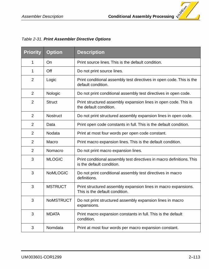
UM003601-COR1299 2–113
Assembler Description Conditional Assembly Processing
Table 2-31. Print Assembler Directive Options
Priority Option Description
1 On Print source lines. This is the default condition.
1 Off Do not print source lines.
2 Logic Print conditional assembly test directives in open code. This is the default condition.
2 Nologic Do not print conditional assembly test directives in open code.
2 Struct Print structured assembly expansion lines in open code. This is the default condition.
2 Nostruct Do not print structured assembly expansion lines in open code.
2 Data Print open code constants in full. This is the default condition.
2 Nodata Print at most four words per open code constant.
2 Macro Print macro expansion lines. This is the default condition.
2 Nomacro Do not print macro expansion lines.
3 MLOGIC Print conditional assembly test directives in macro definitions. This is the default condition.
3 NoMLOGIC Do not print conditional assembly test directives in macro definitions.
3 MSTRUCT Print structured assembly expansion lines in macro expansions. This is the default condition.
3 NoMSTRUCT Do not print structured assembly expansion lines in macro expansions.
3 MDATA Print macro expansion constants in full. This is the default condition.
3 Nomdata Print at most four words per macro expansion constant.

Conditional Assembly Processing Assembler Description
2–114 UM003601-COR1299
The options may be specified in any order. However, only one option from each prioritygroup may be specified, and any given option may be specified at most once.
Options specified on the PRINT directive remain in effect until changed by a subsequentprint directive.
In the absence of any print directive, the default print options are on, logic, struct, data,macro, MLOGIC, MSTRUCT and MDATA.
You must not use a label on this directive.
Example
This example shows how to inhibit listing of macro expansion lines.
PRINT NOMACRO

UM003601-COR1299 2–115
Assembler Description Conditional Assembly Processing
Purpose
The PT assembler directive specifies the column tab stops in the listing file.
Syntax
PT width
Alias
.TAB
Description
The PT assembler directive specifies the column positions of tab stops on the listing file. Ifno listing file is being produced the PT assembler directive has no affect on the assembly.
The required width operand must be an absolute expression. The assembler assumes thatthe tab stops on the listing file device occur at column positions that are multiples of thespecified width. The assembler uses this information, in conjunction with the page widthspecified using the PW assembler directive , to limit the number of characters printed oneach line of the listing file. For example, if the PW is 48, and the PT is 8, up to 6 tabs willbe emitted (6*8=48). But if PT is 16, up to 4 tabs will be emitted (4*16=48).
In the absence of a PT directive, listing file tab stops are assumed to occur at every fourthcolumn position.
There may be any number of PT directives in a source module. The listing file-tab widthspecified on any particular PT directive remains in effect until changed by a subsequent PTdirective.
You must not use a label on this directive.
Example
This example illustrates how to set the listing file tab width.
PT 8
PT Set Tabs In Listing File PT
Conditional Assembly Processing Assembler Description
2–116 UM003601-COR1299
Purpose
The PUBLIC assembler directive identifies a symbol defined in the current source moduleas having global scope.
Syntax
PUBLIC symbol1 [ , symbol2 ] ...
Alias
.DEF
.GLOBAL
XDEF
Description
The PUBLIC assembler directive defines one or more public symbols. A public symbol is asymbol which is defined in the source module that is currently being assembled, but maybe referenced in a different source module.
You may declare any number of public symbols on a single statement, but they must all fiton a single source statement line. Use commas to separate the symbols.
You must not use a label on this directive.
Examples
This example shows how to declare a symbol to be accessible in another source module.
PUBLIC ExFunction
PUBLIC Identify A Global Symbol PUBLIC

UM003601-COR1299 2–117
Assembler Description Conditional Assembly Processing
Purpose
The PW assembler directive specifies the number of columns per page on the listing file.
Syntax
PW width
Alias
.WIDTH
Description
The PW assembler directive controls the number of columns printed on each page of thelisting file. If no listing file is being produced, the PW assembler directive has no affect onthe assembly.
The required width operand must be an absolute expression. The assembler will print nomore than width source statement characters on any line of the listing file. The PT assem-bler directive should be used to tell the assembler how many columns are represented byeach tab stop.
In the absence of a PW directive, the assembler will print all characters of each sourcestatement.
There may be any number of PW directives in a source module. The listing-file width spec-ified on any particular PW directive remains in effect until changed by a subsequent PWdirective.
You must not use a label on this directive.
Example
This example illustrates how to set the listing file width.
PW 80
PW Specify Listing File Page Width PW
Conditional Assembly Processing Assembler Description
2–118 UM003601-COR1299
Purpose
The ROMSIZE assembler directive specifies the size of the microcontroller ROM addressspace.
Syntax
ROMSIZE [ = ] expression
Description
The ROMSIZE assembler directive declares the size of the microcontroller ROM addressspace to be the specified absolute expression. The specified ROM size is used to deter-mine the location of the microcontroller vectors. See the VECTOR assembler directive fora list of available microcontroller vectors, and their possible location.
The required expression operand must be an absolute expression. It specifies the micro-controller ROM size, in K-bytes or K-words.
You must not use a label on this directive.
Example
This example illustrates how to specify the microcontroller ROM size as 8 KB.
ROMSIZE 8
ROMSIZE Specify Microcontroller ROM Size ROMSIZE

UM003601-COR1299 2–119
Assembler Description Conditional Assembly Processing
Purpose
The .SBLOCK assembler directive aligns sections by advancing the location counteruntil a page boundary (128 words) is reached.
Note: This instruction is supported only for Z89C25/50 core.
Syntax
[ label ] .SBLOCK “section” [,”section”,....]
Description
The .SBLOCK assembler directive advance the location counter until a 128-word pageboundary is reached. This instruction allows specification of blocking for initialized sec-tions only, not initialized sections.
The section operand is required, and specifies the control section name. It must be en-closed in double quotes.
You must not use a label on this directive.
Examples
This example show two control sections named: AbsSection and DataSection are des-ignated for blocking.
.sblock “AbsSection”, “DataSection”
.SBLOCK Align Section Until Page Boundary Is Reached .SBLOCK

Conditional Assembly Processing Assembler Description
2–120 UM003601-COR1299
Purpose
The SCOPE assembler directive resets local symbol scoping.
Syntax
SCOPE
Alias
.NEWBLOCK
Description
The SCOPE assembler directive controls the visibility of local symbols. The SCOPE direc-tive delimits regions of visibility of local symbols. Local symbols defined between SCOPEdirectives are visible only between those directives.
You must not use a label on this directive.
Example
This example illustrates how to specify a local symbol scope block.
SCOPE
$Local: NOP
SCOPE
SCOPE Reset Local Symbol Scoping SCOPE
UM003601-COR1299 2–121
Assembler Description Conditional Assembly Processing
Purpose
The .SECT assembler directive makes a named control section the current control section.
NOTE: This directive is supported only for the Z89C25/50 core.
Syntax
.SECT section
Description
The .SECT assembler directive makes the named control section the current control sec-tion; the assembler begins assembling into the named section.
The section operand is required, and specifies the control section name. It must be en-closed in double quotes.
You must not use a label on this directive.
Example
This example illustrates how to make a named section the current control section.
.SECT “Typesetting”
.SECT Assemble Into Named Control Section .SECT
Conditional Assembly Processing Assembler Description
2–122 UM003601-COR1299
Purpose
The SEGMENT assembler directive specifies the name of the current control section.
Syntax
SEGMENT name
Description
The SEGMENT assembler directive specifies the name of a previously defined control sec-tion, and makes that control section the current control section. See the DEFINE assemblerdirective for a description of how control sections are defined.
The appearance of a SEGMENT directive causes the assembler to place all subsequentobject code in the named control section. For dual processors such as Z89175, Z89C95,and Z89C65, use “SEGMENT Code” for DSP code, and “SEGMENT Text” for Z8 code.
You must not use a label on this directive.
Example
This example illustrates how to define a control section, and make it the current control sec-tion.
DEFINE Code1 ; Define a code control section
DEFINE Code2 ; Define another code control section
SEGMENT Code1 ; Make section 'Code1' the current section
NOP ; Assemble into control section 'Code1'
SEGMENT Code2 ; Make section 'Code2' the current section
NOP ; Assemble into control section 'Code2'
SEGMENT Code1 ; Make section 'Code1' the current section
NOP ; Assemble into control section 'Code1'
SEGMENT Specify The Current Control Section SEGMENT

UM003601-COR1299 2–123
Assembler Description Conditional Assembly Processing
Purpose
The .STRUCT, .ENDSTRUCT, and .TAG assembler directives enables the assemblerto group similar data elements calculate each element’s offset value. This is approachsimilar to high-level programming language structures like a C structure or a PASCALrecord.
NOTE: These instructions are supported only for Z89C25/50 cores.
Syntax
[slabel]. STRUCT [expression][memloc0] element [expression0][memloc1] element [expression1]
. . .
. . .
. . .[memlocN] element [expressionN][size] .ENDSTRUCTlabel .TAG slabel
Description
The .STRUCT assembler directive assigns symbolic offsets to the elements of a datastructure definition. The .STRUCT directive does not allocate memory; it merely cre-ates a symbolic template that can be used repeatedly.
The .ENDSTRUCT assembler directive terminates the structure definition.
The .TAG assembler directive declares or assign a label to have a structure type. The.TAG does not allocate memory. When assigning a label to a structure, the structuremust have been previously defined.
The following terms are used in conjunction with the .STRUCT, .ENDSTRUCT, and.TAG directives:
slabel is the structure’s tag.element is one of the following assembler directives: .BYTE, .WORD, .FLOAT,.STRING, .TAG.
STRUCT/.ENDSTRUCT/.TAG .STRUCT/.ENDSTRUCT/.TAGGroup Data Elements

Conditional Assembly Processing Assembler Description
2–124 UM003601-COR1299
expression is an optional expression indicating the beginning offset of the struc-ture. Default value is 0.memlocN is an optional label indicating the present offset of each element of the
structure. A label for a structure cannot be declared globally.expressionN is an optional expression for the number of elements described. This
value defaults to 1.size is an optional label whose offset shows the total size of structure.
Example
00000000 DataBank .struct 2
00000002 DOB .string 16
00000012 AGE .int
00000013 SIZE .endstruct

UM003601-COR1299 2–125
Assembler Description Conditional Assembly Processing
Purpose
The TITLE and SUBTITLE assembler directives define titles and subtitles to be printed onthe assembly listing.
Syntax
TITLE title
SUBTITLE subtitle
Alias
TITLE: .TITLE
Description
The TITLE assembler directive causes the title string to appear in the assembler listingheading title line, and the SUBTITLE directive causes the subtitle string to appear in theassembler listing heading sub-title line. These directives have no effect on the assembly ifno listing file is being produced.
The TITLE and SUBTITLE assembler directives require a single operand, namely, the titleor subtitle to be printed on the listing file heading. The title or subtitle must be enclosed indouble quotes.
You must not use a label on these directives.
Example
This example illustrates how to specify a listing file title and subtitle.
TITLE “Listing file title”
SUBTITLE “Listing file subtitle”
SUBTITLE/TITLE Define Listing Subtitle SUBTITLE/TITL E

Conditional Assembly Processing Assembler Description
2–126 UM003601-COR1299
Purpose
The TARGET assembler directive specifies the target microcontroller CPU.
Syntax
TARGET cpu
Description
The TARGET assembler directive specifies the target microcontroller CPU, allowing as-sembly of machine directives for that processor. This directive is valid only for those micro-controllers that have multiple CPU directive sets, such as the Z86C95. See the CHIPassembler directive for a description of how to select a microcontroller type.
The required cpu operand is a literal token specifying the CPU type. The supported typesare listed in the following table.
You must not use a label on this directive.
Example
This example illustrates how to specify the microcontroller CPU directive set.
TARGET DSP
Table 2-32. Supported Types
Chip MCU Target CPU Instruction Set
Z86C95 Z8 Standard Z8
DSP Z89C00
TARGET Specify Target Microcontroller CPU TARGET

UM003601-COR1299 2–127
Assembler Description Conditional Assembly Processing
Purpose
The .TEXT assembler directive makes the .text control section the current control section.
NOTE: This directive is supported only for the Z89C25/50 core.
Syntax
.TEXT
Description
The .TEXT assembler directive makes the .TEXT control section the current control sec-tion; the assembler begins assembling into the . text section.
You must not use a label on this directive.
Example
This example illustrates how to make the .TEXT section the current control section.
.TEXT
.TEXT Make .TEXT Control Section The Current Section .TEXT

Conditional Assembly Processing Assembler Description
2–128 UM003601-COR1299
Purpose
The .USECT assembler directive reserves uninitialized space in a named control section.
NOTE: This directive is supported only for the Z89C25/50 core.
Syntax
symbol .USECT section, length
Description
The .USECT assembler directive reserves length uninitialized addresses in the named con-trol section, and assigns the value of the first reserved address to the named symbol.
The symbol operand is required, and names a symbol to be assigned the value of the firstaddress allocated by the directive in the named control section.
The section operand is required, and names a control section in which space is to be re-served. The section name must be enclosed in double quotation marks.
The length operand is required, and specifies the number of addresses to be reserved inthe named control section. A comma must be entered between the section and length op-erands.
Example
This example illustrates how to allocate four addresses in a named section, and assign alabel to the first address allocated.
VarLabel .USECT “TempSection”,4
.USECT Reserve Uninitialized Space .USECT

UM003601-COR1299 2–129
Assembler Description Conditional Assembly Processing
Purpose
The VECTOR assembler directive initializes a microcontroller vector.
Syntax
VECTOR name = expression
Description
The VECTOR assembler directive initializes a processor vector location with the specifiedaddress expression. See the ROMSIZE assembler directive for a description of how tospecify the microcontroller ROM size, which might affect the location of the microcontrol-ler's vectors.
The VECTOR assembler directive accepts one operand. The operand has the form name= expression, where the literal token = may be surrounded by whitespace, the name is thename of an exception vector and the expression is a relocatable expression.
Valid interrupt vector names depend upon the target microcontroller. Z8 Family vectors aresummarized in Table 2-33.The Z89C00 vectors are summarized in Table 2-34.
Table 2-33. Vector Locations
Name Location Comments
IRQ0 %0000
IRQ1 %0002
IRQ2 %0004
IRQ3 %0006
IRQ4 %0008
IRQ5 %000A
RESET %000C The assembler generates a JP instruction at address %000C to the address specified on the VECTOR instruction.
VECTOR Initialize Microcontroller Vector VECTOR

Conditional Assembly Processing Assembler Description
2–130 UM003601-COR1299
Table 2-34. Z89C00 Family Vectors
Name Location Comments
RESET %XYFC XY depends on ROMSIZE.
INT2 %XYFD
INT1 %XYFE
INT0 %XYFF

UM003601-COR1299 3–1
ZILOG MACRO CROSS ASSEMBLER
CHAPTER 3
MACRO LANGUAGE
INTRODUCTION
A macro is a single, symbolic statement that results in a series of substituted statements when it is translated.
A macro can be thought of as simple source code substitution. For example, if macro XYZ is defined as “instr1, instr2, and instr3”, then every time you use XYZ in your source code, the assembler sub-stitutes and assembles “instr1, instr2, and instr3” automatically for you. Macros also can be thought of as “in-line” subroutines, whereby the “CALL SUBR” is replaced by the actual SUBR code for each occurrence (call).
Macros shorten and simplify source programming because you can use a single instruction to rep-resent entire blocks of statements that, otherwise, would be used repetitively throughout a program. Macros help you avoid the tedium of repeatedly coding and verifying a common sequence of state-ments. The macro processor also supports parameterizing a block of statements so that variations in the block also can be called out.
Macro Assembler InstructionsA macro assembler instruction is coded similarly to a machine instruction: a mnemonic operation code is specified, along with any required operands. When a macro is used, however, the mnemon-
Chapter Topics:Defining Macros
Calling Macros
Expanding Macros
Substituting Symbols
Referencing System Symbols

Introduction Macro Language
3–2 UM003601-COR1299
ic operation code is the name of a previously defined macro, and the operands are designated as parameters to the macro. The actual parameters specified in the call replace formal parameters that appear in the body of the macro.
The assembler instructions associated with the macro processor are shown in the following table. (Chapter 3 provides a complete description of all assembler instructions, including those shown in Table 4-1.)
Table 3-1. Macro Assembler Instructions
Macro AssemblerInstructions Description
MACRO Macro Definition Header
MACCNTR Macro Counter
MACEND Macro Definition Trailer
MACEXIT Macro Definition Exit
MACNOTE Macro Note

UM003601-COR1299 3–3
Macro Language Using Macros
USING MACROS
The formation and translation of macros involves three distinctive steps:
1. Macro Definition. The macro definition associates a macro name with a block of sourcestatements.
2. Macro Call. The macro call names a previously defined macro, and the associated macro bodyis expanded at the point where the call appears.
3. Macro Expansion. The process of replacing a macro call with a macro body is known as macroexpansion.
Each of these steps is now explained in greater detail in the sections that follow.
Macro DefinitionMacros are defined using the MACRO (.MACRO) and MACEND (.ENDM, ENDMAC) assembler in-structions. (Chapter 3 provides a complete description of these assembler instructions.) The MAC-RO instruction denotes the beginning of the macro definition; the MACEND instruction denotes the end of the macro definition. The name of the macro and the names of its formal parameters are specified by the MACRO instruction. Statements within the MACRO and MACEND instructions con-stitute the macro body. Such statements may be assembler instructions, machine instructions, or comments (see Figure 4-1).
Macro definitions can be nested inside other macro definitions (see “Nested Macro Definitions” sec-tion, which follows).
Macro definitions are frequently kept in a separate source file, and included in the assembled source module using the INCLUDE assembler instruction. (For more information on the INCLUDE instruction, refer to Chapter 3.)
Syntax:
macroname Names the macro. The macroname represents any valid assembler symbol, including a previously defined macro. The macroname is al-ways required. Unnamed macros, therefore, are not supported.
macroname MACRO [fParameter1 [fParameter2 ] . . .] [;comment]
statements
MACEND [; comment]
Using Macros Macro Language
3–4 UM003601-COR1299
MACRO A directive identifying the first line of a macro definition. “MACRO” must be placed in the opcode field.
fparametern Substitution symbols for the MACRO directive. (Using parameters is explained more fully in the “Macro Call” section, which follows.)
;comment Any text statement. There are two types of comments: “ordinary” and “macro”. (Using comments is explained more fully in the “Macro Call” section, which follows.)
statements Instructions that are substituted each time the macro is called.
MACEND Ends the macro definition.

UM003601-COR1299 3–5
Macro Language Using Macros
Rules Governing Macro Definition
■ A macro can be defined anywhere in the source assembly, if it appears before the first source linethat calls the macro.
■ A macro definition remains in effect for the rest of the source module, or until another macrodefinition specifying the same macro name redefines the definition.
■ The new definition will be used for all subsequent calls to the macro in the source module.
Figure 3-1. General Format of Macro Definition
macro
.
.
.statements
.
.
.
macend
Macro Header
Macro Body
Macro Trailer

Using Macros Macro Language
3–6 UM003601-COR1299
Nested Macro DefinitionsMacro definitions can appear inside other macro definitions. Such definitions are said to be nested. There is no limit on the level of macro definition nesting.
A macro that is defined within another macro definition is called an inner macro definition. A macro definition that contains another macro definition is called an outer macro definition. Thus, a macro definition may be both an outer and an inner macro definition. But with respect to different macro definitions, it is an outer definition with respect to the definitions it contains, and it is an inner defi-nition with respect to the macro definition within which it is defined.
Nested macro definitions are not processed until the inner macro definition is encountered during the expansion of the outer macro definition. This means that the macro defined in the inner defini-tion will not be known to the assembler until the outer macro is called. For example, consider the source code fragment shown in Figure 4-2. The assembler does not process the macro definition for inner until outer is called with a non-null value for the parameter p1.
Macro Definition Validity ChecksThe following validity checks are performed on the input data. Unless otherwise specified, violations result in an error message, and the assembly fails.
1. The MACRO and MACEND instructions must be balanced: there must be exactly oneMACEND instruction for each MACRO instruction, and the MACRO instruction must precedeits corresponding MACEND instruction.
2. The macro definition must be completely specified within a single assembly unit. An assemblyunit in this context is a single source file, or a single macro definition. Thus, if the MACROinstruction appears in source file filea, the corresponding MACEND instruction must also
Figure 3-2. Example of a Nested Macro Definition
outer macro pl...
ifnb plinner macro
.
.
.macend ;;innerendif
.
.
.macend ;;outer
UM003601-COR1299 3–7
Macro Language Using Macros
appear in source file filea. Similarly, if the MACRO instruction appears within the body ofmacroa, the MACEND instruction must also appear within the body of macroa.
3. It is valid to code INCLUDE assembler instructions in the body of a definition. However, like allinstructions in the macro body, the INCLUDE instruction is not processed until the macro iscalled.
4. There is no previously defined limit on the number of macros that may be defined or the numberof statements that appear in the macro body. However, the host operating system may imposesome limit on the size of the symbol table or size of the macro library, due to the physicallimitations of the host machine. Symbol table and Macro library overflow is considered to be anerror condition.

Using Macros Macro Language
3–8 UM003601-COR1299
Macro CallA macro call causes the assembler to expand a macro definition by processing the statements of the macro definition body at the point where the macro call instruction appears. Expansion includes replacing the formal parameters in the macro body with the actual parameters specified on the mac-ro call instruction.
Syntax
label The label is optional. If specified, it is handled in the normal way. (Chapter 3 provides more information on the Assembler Source Statement Label Field.)
macroname The macroname must be the name of a previously defined macro. By definition, if macroname is not the name of a previously defined macro, then the instruction is not a macro call. Thus, it is not possible to call a macro before it has been defined.
aparametern The aParametern parameters specify the n actual parameters passed to the macro. The aParameters can be arbitrary strings of ASCII characters, excluding space and commas.
There can be any number of aParameters, although they must all fit on one source line. There may not be more (but there may be fewer) actual parameters than there were formal parameters specified in the macro definition.The actual and formal parameters are paired positionally. Thus, aParameter1 of the macro call corresponds to aParametern of the macro definition.
If more than one aParameter is specified, the individual aParameters must be separated by commas. If an aParameter is to include embedded spaces or commas, then it must be quoted by enclosing it in matched pair macro quotes (“<” and “>”). Whitespace may surround the commas.
An aParameter may be omitted by coding only whitespace, or nothing, in its place. It is valid to code a separator at the end of a statement, signify-ing that all subsequent aParameters have been omitted. There is, how-ever, a semantic difference between coding a trailing separator, as op-posed to omitting both the separator and the aParameter: If a separator is specified, the macro processor considers the aParameters before and
[label:] macroname [aParameter1 [, aParameter2 ] . . .] [;comment]

UM003601-COR1299 3–9
Macro Language Using Macros
after the separator to have been specified. Thus, the trailing aParameter will be a null parameter.
Leading and trailing whitespace characters are not considered to be part of the string, nor are the aParameter separators (,). Embedded whitespace characters are considered to be part of the string.
Each aParameter may be up to 255 characters long (leading and trailing whitespace characters do not count toward this maximum).
aParameter cannot be a reserved word, such as register names.
;comments Comments in the statements are one of two types: ordinary comments and macro comments. Ordinary comments are coded in the normal way, that is, by introducing them with the ordinary comment character (;). Mac-ro comments are coded by introducing them with the macro comment characters—two consecutive ordinary comment characters (;;). Ordinary comments are saved in the macro library as part of the macro definition. Macro comments are not saved in the macro library.
Macro ExpansionThe macro processor places macro definitions into a macro library. The ZMASM first looks in the macro library when it encounters an opcode. If not found, then it looks in the standard opcode table. Standard opcodes, therefore, can be redefined by using macros. A macro call causes the assem-bler to retrieve the macro definition body from the macro library for the named macro. Statements in the macro body are expanded by replacing formal parameters of the definition with actual param-eters of the call at points of substitution in the macro body statements. The expanded statements are then assembled (see Figure 4-3).
Symbol SubstitutionThe process of replacing formal parameter names with their actual values is known as symbol sub-stitution. It occurs during pre-assembly. The rules for symbol substitution apply only during macro expansion; they do not apply when the assembler is assembling a statement. Symbol substitution is performed only once on any given source statement.
Symbol substitution involves the following steps:
1. Values are assigned. The values of the macro actual parameters are assigned to the macro formal parameters. Actual and formal parameters are paired positionally, from left to right. The ac-tual parameters are not evaluated at this time: they are merely treated as strings of characters. If there are fewer actual parameters than formal parameters, the excess formal parameters are as-signed the null string value. In general, omitted actual parameters cause the null string value to be
Using Macros Macro Language
3–10 UM003601-COR1299
assigned to the corresponding formal parameters. When assigned, the values of formal parameters remain constant throughout the macro call processing.
2. Lines are retrieved. Lines are retrieved from the macro library entry for the named macro, one line at a time, until all lines have been retrieved, or until an MACEXIT assembler instruction is en-countered. As each line is retrieved, the assembler performs a minimal parse to determine the mne-monic in the operation field of the statement. If the mnemonic in the operation field is the MACEXIT assembler instruction, and if the optional exit condition is omitted or true, macro call processing ter-minates. If the mnemonic in the operation field is the MACRO assembler instruction, the macro def-inition processor consumes lines in the macro library up to and including the matching MACEND instruction. Thus, nested macro definitions are not subject to symbol substitution during macro call processing.

UM003601-COR1299 3–11
Macro Language Using Macros
3. Symbol substitution occurs. As each line is retrieved from the macro library, symbol substitu-tion occurs. The result of the substitution is an expanded line, which is distinct from the (unchanged) line in the macro library. A symbol name is substituted with the value of the symbol when the symbol name is prefixed with the symbol substitution operator (\). Such a construct denotes a point of sub-stitution. Only formal parameter names are eligible for substitution. If the substitution operator pre-fixes any other entity, both the operator and the entity are copied unchanged into the expanded line.
Figure 3-3. Macro Definition, Call, and Expansion
Rules Governing Symbol Substitution■ Substitution is performed only when a symbol is prefixed with the substitution operator (\). Thus,
\abc and abc are treated as distinct by the macro processor.
■ Substitution is performed only when the substitution operator (\) is a proper prefix of the formalparameter name. That is, no whitespace characters should separate the substitution operator andthe symbol.
..
..
macro FOO......
macend......
FOO......
Macro Definition
Macro Call
Macro Expansion
Source Module Object Module
Macro Library
Cross Assembler

Using Macros Macro Language
3–12 UM003601-COR1299
■ To facilitate unambiguous symbol substitution during macro expansion, the concatenationcharacter (&) may be suffixed to symbol names that are prefixed by the symbol substitutioncharacter. The concatenation character is a syntactic device for delimiting symbol names that arepoints of substitution, and is devoid of semantic content. The concatenation character, therefore,is discarded by the assembler, when the character has delimited a symbol name (see Table 4-2).
■ Substitution is performed within string constants. To encode the symbol substitution operator (\) asa literal character within string constants, the symbol substitution operator must be encoded twice.
■ Symbol substitution is not performed within comments. It is performed everywhere else.
■ After symbol substitution has taken place, the expanded line is assembled, as if it had appearedin the original source file.
Macro Processor OutputsThe macro expansions may appear in the listing file. If the statements in the macro expansions cause any object code to be generated, then the generated object code appears in the object mod-ule.
If any errors are detected during macro processing, then error messages are generated. Error mes-sages are written to the messages file and to the listing file, if one is being produced.
During macro expansion, the macro processor attempts to generate an expansion line in a reason-able way, so that the expanded line is formatted in approximately the same way as the unexpanded line in the macro definition body. Thus, the programmer may more easily assimilate the expanded line, should it appear in the listing file.
A source statement is partitioned into four fields (refer to Chapter 3 for more information):
1. Label field
Table 3-2. Examples of Symbol Substitution and Concantenation
Before Substitution Parameter Name Parameter Value
After Substitution
\SYMBOL&A SYMBOL VALUE VALUEA
“\SYMBOLA” SYMBOLA “STRING” “STRING”
\INTEGER&.&FRACTION
INTEGERFRACTION
123456
123.456

UM003601-COR1299 3–13
Macro Language Using Macros
2. Operation field
3. Operand field
4. Comment field
Prior to beginning macro expansion on a given source line in a macro definition body, the assembler notes the positions of these fields on the unexpanded source line.
After expansion, the expanded line has the corresponding fields beginning in the same columns in which they began on the unexpanded line.
NOTES:
1. If the substituted value in the label or operation field is too large for the space available forthe field, the next field is moved to the right, with a single space character separating thefields.
2. If the substituted value in the operand field causes the comment field to be displaced, thecomment field is generated on a separate line, starting in the column where the commentfield appeared on the unexpanded line. The generated comment line is processed afterprocessing the original expanded line.

Referencing System Symbols Macro Language
3–14 UM003601-COR1299
REFERENCING SYSTEM SYMBOLS
The macro processor maintains a set of system symbols that may be usefully referenced as points of substitution in a macro body. The system symbols are implicitly maintained by the assembler. It is not possible for the programmer to directly change the value of a read-only system symbol.
Formal parameter names specified on macro definitions must be unique with respect to system symbols.
The rules for substitution apply equally well to system symbols and macro formal parameters.
Like macro formal parameter values, system symbol values are constants with local macro scope. This means that their value does not change during a given macro call, and they can only be refer-enced inside a macro definition, where inside a macro definition refers to the statements between the MACRO and MACEND assembler instructions, that is, the statements that make up the macro body.
The following table lists the symbol names. A brief description of each System Symbol follows.
System Symbol $SYSECT■ The $SYSECT system symbol contains the name of the control section current at the point of the
macro call.
■ The $SYSECT system symbol is a string-valued symbol.
■ The value of $SYSECT is the name of the control section from which a macro is called.
■ The value of $SYSECT remains constant throughout a macro call, even if the macro call generatesinstructions that change the current control section name, such as the SEGMENT assemblerinstruction.
■ If $SYSECT is used as a point of substitution, the value substituted is a string of charactersdenoting the name of the control section from which the macro was called.
Table 3-3. System Symbol Names and Descriptions
System Symbol Description
$SYSSECT Current control section name.
$SYSLST The number of actual parameters on a macro call.
$SYSNDX The ordinal number of a macro call.

UM003601-COR1299 3–15
Macro Language Referencing System Symbols
■ To be used as a point of substitution, the $SYSECT system symbol must be coded in all uppercaseletters.

Referencing System Symbols Macro Language
3–16 UM003601-COR1299
Macro Processor System Symbol $SYSLST■ The $SYSLST system symbol records the number of actual parameters specified on a macro call.
This includes impeded null parameters.
■ The $SYSLST system symbol is an integer-valued symbol.
■ The value of $SYSLST is the number of actual parameters specified on the macro call instruction.
■ An actual parameter is considered to have been specified if the comma that delimits it from thesucceeding parameter is specified.
■ The value of $SYSLST remains constant throughout a macro call.
■ If $SYSLST is used as a point of substitution, the value substituted is a string of decimal digitsrepresenting the number of actual parameters specified on the macro call instruction.
■ To be used as a point of substitution, the $SYSLST system symbol must be coded in all uppercaseletters.
Macro Processor System Symbol $SYSNDX■ The $SYSNDX system symbol maintains a count of the number of macro call instructions that have
been processed.
■ The $SYSNDX system symbol is an integer-valued symbol with a non-negative value.
■ The value of $SYSNDX is the number of times macro call instructions have been encounteredduring assembly of the source module.
■ The value of $SYSNDX remains constant throughout a macro call.
■ If $SYSNDX is used as a point of substitution, the value substituted is a string of decimal digitsrepresenting the number of times macro call instructions have been assembled. The range ofvalues of $SYSNDX is from 1 to 232 -1. If the value of $SYSNDX is less than 10,000 when usedas a point of substitution, the substituted value is a string of four decimal digits, with leading zerosprepended if necessary. If the value of $SYSNDX is greater than or equal to 10,000 when used asa point of substitution, the substituted string has no leading zeros.
■ The value of $SYSNDX wraps from 232 -1 to 1. That is, $SYSNDX never has the value zero.
■ To be used as a point of substitution, the $SYSNDX system symbol must be coded in alluppercase letters.

UM003601-COR1299 3–17
Macro Language Referencing System Symbols
Macro Substitution Example:
A 1 Res_W macro par1, par2
A 2 DW \par1&Fh
A 3 .float \par2&. &5
A 4 macend
A 5 Res W 2, 3
00000000 002F A+ 5 DW 2Fh
00000001 0000 4040 A+ 5 .float 3. &5


UM003601-COR1299 4–1
ZILOG MACRO CROSS ASSEMBLER
CHAPTER 4
LINKER DESCRIPTION
INTRODUCTION
The purpose of the Zilog cross linker is to create a single executable load module by combining mul-tiple Relocatable objects. The linker works both as an integrated component of Zilog’s Support Product toolset and as a stand-alone, full-featured linker for use by assembly language program-mers. In particular, the linker is tailored to meet the needs of developers writing embedded applica-tions for Zilog’s embedded system microcontrollers.
This chapter briefly describes the linker’s inputs and outputs, and how the inputs to the linker are transformed into those outputs. (Refer to Table 5-1, which explains various linker acronyms and ab-breviations.)
What Does the Linker Do?The linker performs the following fundamental actions, which are briefly detailed in the section that follows:
■ Reads in Relocatable object modules and library files in Zilog’s Object Module Format (ZOMF)
■ Resolves external references
■ Assigns absolute addresses to Relocatable sections
■ Supports Source-Level Debugging (SLD)
Chapter Topics:Linker Functions
Invoking the Linker
Linker Options
Linker Output Files
Linker Messages

Introduction Linker Description
4–2 UM003601-COR1299
■ Generates a single executable module to download into the target system or burn into OTP orEPROM programmable devices
■ Generates a map file
■ Generates ZOMF files (for Libraries)
Linkage EditingThe linker creates a single executable load module from multiple Relocatable objects.
Resolving External ReferencesAfter having read multiple object modules, the linker searches through each of them to resolve ex-ternal references to the public symbols. It looks for the definition of public symbols corresponding to each external symbol in the object modules.
Relocating AddressesThe linker allows the user to specify where the code and data are stored in the target processor system’s memory at run-time. The important task of fixing up all relocation addresses within each section to an absolute address is handled in this phase.
Debugging SupportWhen the debug option is specified, the linker creates an executable file that can be loaded into the debugger at run-time. A warning message is generated if any of the object modules do not contain a special section that has debug symbols for the corresponding source module. Such a warning indicates that a source file was compiled or assembled without turning on a special switch that tells the compiler or assembler to include debug symbols information while creating a Relocatable object module.
Outputting Map FilesThe linker can be directed to create a “map file” that details the location of the Relocatable sections and Public Symbols.
Outputting OMF FilesDepending upon the user-specified option specified by the user, the linker can produce two types of OMF files:
■ Intel Hex Format Executable File
■ ZOMF Format Executable File
Zilog’s Integrated Development EnvironmentThe linker is a part of the integrated development environment that supports Zilog’s family of micro-controllers. Thus, the linker is designed to be used in conjunction with the other tools that make up the Zilog integrated development environment.
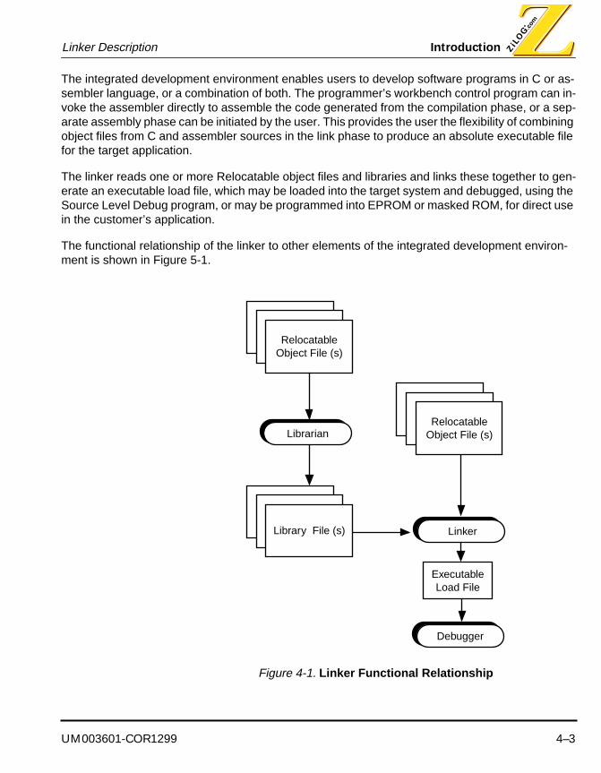
UM003601-COR1299 4–3
Linker Description Introduction
The integrated development environment enables users to develop software programs in C or as-sembler language, or a combination of both. The programmer’s workbench control program can in-voke the assembler directly to assemble the code generated from the compilation phase, or a sep-arate assembly phase can be initiated by the user. This provides the user the flexibility of combining object files from C and assembler sources in the link phase to produce an absolute executable file for the target application.
The linker reads one or more Relocatable object files and libraries and links these together to gen-erate an executable load file, which may be loaded into the target system and debugged, using the Source Level Debug program, or may be programmed into EPROM or masked ROM, for direct use in the customer’s application.
The functional relationship of the linker to other elements of the integrated development environ-ment is shown in Figure 5-1.
Figure 4-1. Linker Functional Relationship
Librarian
ExecutableLoad File
Relocatable Object File (s)
Library File (s)
Relocatable Object File (s)
Linker
Debugger

Introduction Linker Description
4–4 UM003601-COR1299
Acronyms and AbbreviationsThe following table lists terms and abbreviations used throughout this chapter.
Table 4-1. Acronyms and Abbreviations
Term Meaning
Address Space A physical or logical area of the target system’s memory map. The memory map could be physically partitioned into ROM to store code, and RAM for data. The memory can also be divided logically to form separate areas for code and data storage.
Cross Linkage Editor A linkage editor that executes on a processor that is not the same as the target processor.
External Symbol A symbol that is referenced in the current program file but is defined in another program file.
Groups Groups are collections of logical address spaces. They are typically used for convenience of locating a set of address spaces.
Internal Symbol A symbol that is defined in a program file. This symbol could be visible to multiple functions within the same program file.
Library A file created by a librarian. This file contains a collection of object modules that were created by an assembler or directly by a C compiler.
Local Symbol A symbol that is visible only to a particular function within a program file.
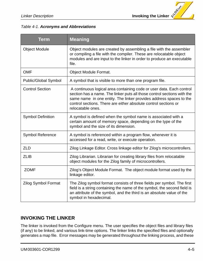
UM003601-COR1299 4–5
Linker Description Invoking the Linker
INVOKING THE LINKER
The linker is invoked from the Configure menu. The user specifies the object files and library files (if any) to be linked, and various link-time options. The linker links the specified files and optionally generates a map file. Error messages may be generated throughout the linking process, and these
Object Module Object modules are created by assembling a file with the assembler or compiling a file with the compiler. These are relocatable object modules and are input to the linker in order to produce an executable file.
OMF Object Module Format.
Public/Global Symbol A symbol that is visible to more than one program file.
Control Section A continuous logical area containing code or user data. Each control section has a name. The linker puts all those control sections with the same name in one entity. The linker provides address spaces to the control sections. There are either absolute control sections or relocatable ones.
Symbol Definition A symbol is defined when the symbol name is associated with a certain amount of memory space, depending on the type of the symbol and the size of its dimension.
Symbol Reference A symbol is referenced within a program flow, whenever it is accessed for a read, write, or execute operation.
ZLD Zilog Linkage Editor. Cross linkage editor for Zilog’s microcontrollers.
ZLIB Zilog Librarian. Librarian for creating library files from relocatable object modules for the Zilog family of microcontrollers.
ZOMF Zilog’s Object Module Format. The object module format used by the linkage editor.
Zilog Symbol Format The Zilog symbol format consists of three fields per symbol. The first field is a string containing the name of the symbol, the second field is an attribute of the symbol, and the third is an absolute value of the symbol in hexadecimal.
Table 4-1. Acronyms and Abbreviations
Term Meaning
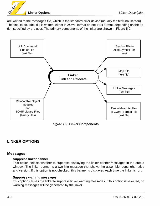
Linker Options Linker Description
4–6 UM003601-COR1299
are written to the messages file, which is the standard error device (usually the terminal screen). The final executable file is written, either in ZOMF format or Intel Hex format, depending on the op-tion specified by the user. The primary components of the linker are shown in Figure 5-2.
Figure 4-2. Linker Components
LINKER OPTIONS
MessagesSuppress linker bannerThis option selects whether to suppress displaying the linker banner messages in the outputwindow. The linker banner is a two-line message that shows the assembler copyright noticeand version. If this option is not checked, this banner is displayed each time the linker is run.
Suppress warning messagesThis option causes the linker to suppress linker warning messages. If this option is selected, nowarning messages will be generated by the linker.
LinkerLink and Relocate
Link CommandLine or File
(text file)
Relocatable Object Modules
andZOMF Library Files
(binary files)
Executable Intel Hex or ZOMF Format File
(text file)
Linker Messages (text file)
Map File (text file)
Symbol File in Zilog Symbol For-
mat
UM003601-COR1299 4–7
Linker Description Linker Options
Treat warnings as errorsThis option causes the linker to treat linker warnings as errors. If this option is selected, and awarning message is generated during a link, the linker will not produce an output file, and thebuild will stop.
OutputGenerate a link map fileThis option generates a linker link map file for the current project. The link map file is namedwith your project’s name with the .MAP extension.
Generate debug informationThis option generates a symbolic debug information in the output file. If this option is notselected no symbolic debug information is generated. If an absolute object file is beinggenerated, then the symbols are written to a separate file (with an extension of .SYM). If a Zilogload file is being generated, the symbols and other debugging information are embedded in theoutput load file.
Generate an absolute object fileThis option generates an absolute object file. If this option is not selected, a load file in ZilogObject Module Format is generated. If this option is selected, an absolute object file in Intel HexObject Format is generated.

Linker Options Linker Description
4–8 UM003601-COR1299
Memory MapMemory Map linker options allow you to specify the ranges for memory address spaces used by the linker for the current project. The linker options allow you to specify additional linker options, and the assembler options allow you to configure the assembler.
You will not normally need to change the values in the Memory Map linker options. Memory address space ranges are set to default values appropriate for the target microcontroller when you created a new project using the New Project Command or change the project target using the Project Target Command.
Address SpacesEach microcontroller has a set of address spaces. You can specify the address range for eachaddress space using the fields in this table.
BoundsYou can select between displaying address spaces in Range format or Length format. In Rangeformat, each address space is displayed as a starting address and an ending address,inclusive. In Length format, each address space is displayed as a starting address and a length.
RadixYou can select between displaying address spaces in base sixteen or in base ten. InHexadecimal radix, each address space field is displayed in base sixteen. In Decimal radix,each address space is displayed in base ten.
Defaultsthe Defaults button restores the address space fields to their default values, based upon currenttarget microcontroller for the project.
RangesLinker range options allow you to specify the address space ranges for sections in the current project. Section ranges are displayed as a scrollable list. The current section range in the list is high-lighted. To highlight a different section range, click on a section range in the list or use the cursor arrow-keys to scroll through the list. There may be multiple entries in the list for a given section name.
New...Click the New button to add a new section range to the list of linker section ranges. The NewSection Range dialog will appear, allowing you to enter the name of the section and addressspace range to which it should be assigned.
Change...Click the Change button to change the value of an existing linker section range. You may alsodouble-click a section range to change its value. The Change Section Range dialog will appear,

UM003601-COR1299 4–9
Linker Description Linker Options
allowing you to change the name of the section or the address space range to which it shouldbe assigned.
DeleteClick the Delete button to delete the current section range.
Symbol DefinitionsLinker Symbol options allow you to define symbols for use by the linker for the current project. Link-er symbols are displayed as a scrollable list. The current symbol in the list is highlighted. To high-light a different symbol, click on a symbol in the list or use the cursor arrow-keys to scroll through the list.
New...Click the New button to add a new symbol to the list of linker symbols. The New Linker Rangedialog will appear, allowing you to enter the name of the symbol name and value.
Change...Click the Change button to change the value of an existing linker symbol. You may also double-click a section range to change its value. The Change Linker Symbol dialog will appear, allowingyou to change the name of the symbol’s value.
DeleteClick the Delete button to delete the current symbol definition.
OrderingLinker Order options allow you to specify a particular ordering of control sections within address spaces for the current project.
Address SpacesEach microcontroller has a set of address spaces. For each address space you may enter a listof control section names, separated by commas. The linker will order the named controlsections within the corresponding address space in the order in which they appear in the list.

Linker Options Linker Description
4–10 UM003601-COR1299
AssignmentsLinker Section Assignments options dialog allows you to specify which address space sections are to be assigned to by the linker for the current project.
Section assignments are displayed as a scrollable list. The current section assignment in the list is highlighted. To highlight a different section assignment, click on a section assignment in the list or use the cursor arrow-keys to scroll through the list.
New...Click the New button to add a new section assignment to the list of linker section assignment.The New Section Assignment dialog will appear, allowing you to enter the name of the sectionand address space to which it should be assigned.
Change...Click the Change button to change the value of an existing linker section assignment. You mayalso double-click a section assignment to change its value. The Change Section Assignmentdialog will appear, allowing you to change the name of the section or address space to which itshould be assigned.
DeleteClick the Delete button to delete the current section assignment.
CopiesLinker Copy options dialog allow you to specify which section are to be copied by the linker for the current project.
Copy sections are displayed as a scrollable list. The current copy section in the list is highlighted. To highlight a different copy section, click on a copy section in the list or use the cursor arrow-keys to scroll through the list.
New...Click the New button to add a new copy section to the list of linker copy sections. The New CopySection dialog will appear, allowing you to enter the name of the copy section and addressspace to which it should be copied.
Change...Click the Change button to change the value of an existing linker copy section. You may alsodouble-click a section assignment to change its value. The Change Copy Section dialog willappear, allowing you to change the name of the copy section or address space to which itshould be copied.
DeleteClick the Delete button to delete the current copy section.

UM003601-COR1299 4–11
Linker Description The Link Map File
THE LINK MAP FILE
At the end of the linking process, the linker produces a map file, if the -m option is specified. A sample map file is shown in this section. The map file is partitioned into labeled sections. Comments have been added to briefly describe each labeled section.
Zilog Linkage Editor. Version 1.00 16-Feb-96 11:57:30 Page: 1
LINK MAP: ;summarizes the link, specifies the link;date, the target microcontrol-ler, and the names ;and types of the linked files.
Date: Fri Feb 16 11:57:30 1996
Processor: Z89C00
Files: [Object ] c00.o
COMMAND LIST: ;lists the command and options that are in;effect. Options from the linker command line, ;as well as com-mands and options read from linker ;command files, appear in this section of the link map.
-oc00 -mc00 c00.o
_Zilog Linkage Editor. Version 1.00 16-Feb-96 11:57:30 Page: 2

The Link Map File Linker Description
4–12 UM003601-COR1299
SPACE ALLOCATION: ;specifies the address space al-location.
Space Base Top Span-------------------------------- -------- -------- --------
ROM 00000000 00000FFF 1000h
RAM0 00000000 00000011 12h
RAM1 00000100 00000119 1Ah
CONTROL SECTIONS WITHIN SPACE: ;enumerates the control sec-tions allocated;within each address space.
ROM Type Base Top Span-------------------------------- ----------- -------- -------- ----
$Vector absolute 00000FFC 00000FFF 4h
abscs absolute 00000800 0000082C 2Dh
atext relocatable 00000000 0000005B 5Ch
code relocatable 0000005C 0000073F 6E4h
text relocatable 00000740 000007A7 68h
RAM0 Type Base Top Span-------------------------------- ----------- -------- -------- ----
absb0 absolute 00000082 00000081 0h
b0ram relocatable 00000000 00000000 1h
bank0_bss relocatable 00000001 00000011 11h
RAM1 Type Base Top Span-------------------------------- ----------- -------- -------- ----
absb1 absolute 00000181 00000180 0h
b1ram relocatable 00000100 00000119 1Ah
UM003601-COR1299 4–13
Linker Description The Link Map File
_Zilog Linkage Editor. Version 1.00 16-Feb-96 11:57:30 Page: 3

The Link Map File Linker Description
4–14 UM003601-COR1299
CONTROL SECTIONS WITHIN MODULES: ;enumerates the control sec-tions from each input ;object module.
Module: c00.s (File: c00.o) Fri Feb 16 11:57:15 1996
Name Base Top Size -------------------------------- -------- ------- -----
Control section: $Vector 00000FFC 00000FFF 4
Control section: abscs 00000800 0000082C 45
Control section: atext 00000000 0000005B 92
Control section: code 0000005C 0000073F 1764
Control section: text 00000740 000007A7 104
Control section: absb0 00000082 00000082 0
Control section: b0ram 00000000 00000000 1
Control section: bank0_bss 00000001 00000011 17
Control section: absb1 00000181 00000181 0
Control section: b1ram 00000100 00000119 26
_Zilog Linkage Editor. Version 1.00 16-Feb-96 11:57:30 Page: 4
EXTERNAL DEFINITIONS BY ADDRESS: ;lists the global symbols, sort-ed by address.
Symbol Address Module Control Section-------------------------------- -------- ----------- ---------------
.textlab 00000001 c00.s atext
begin 00000069 c00.s code
codelab 0000006A c00.s code
firloop 0000006A c00.s code
p0label 0000006F c00.s code
abslabel 00000070 c00.s code

UM003601-COR1299 4–15
Linker Description The Link Map File
addlabel 00000083 c00.s code
andlabel 000000E1 c00.s code
calllabel 00000117 c00.s code
cplabel 000001C4 c00.s code
declabel 000001FA c00.s code
inclabel 0000020D c00.s code
jplabel 00000220 c00.s code
ldlabel 000002D2 c00.s code
mldlabel 000004C4 c00.s code
mpyalabel 000004ED c00.s code
mpyslabel 00000515 c00.s code
neglabel 0000053D c00.s code
orlabel 00000551 c00.s code
poplabel 0000057B c00.s code
pushlabel 000005EE c00.s code
rllabel 00000687 c00.s code
rrlabel 0000069A c00.s code
slllabel 000006AF c00.s code
sralabel 000006C3 c00.s code
sublabel 000006D6 c00.s code
label1 0000072E c00.s code
label2 00000738 c00.s code
textlab 0000075C c00.s text
here 0000075E c00.s text
abslab 00001009 c00.s abscs
bs0lab1 00000000 c00.s b0ram
bs0label 00000011 c00.s bank0_bss
ab0lab0 00000103 c00.s absb0
bs1lab1 00000100 c00.s b1ram
bs1lab0 00000109 c00.s b1ram

The Link Map File Linker Description
4–16 UM003601-COR1299
bs1label 00000119 c00.s b1ram
ab1lab0 00000301 c00.s absb1
38 External symbols.
_Zilog Linkage Editor. Version 1.00 16-Feb-96 11:57:30 Page: 5

UM003601-COR1299 4–17
Linker Description The Link Map File
EXTERNAL DEFINITIONS BY NAME: ;lists the global symbols, sort-ed by symbol ;name.
Symbol Address Module Control Section
-------------------------------- ------- ------- ---------------
.textlab 00000001 c00.s atext
ab0lab0 00000103 c00.s absb0
ab1lab0 00000301 c00.s absb1
abslab 00001009 c00.s abscs
abslabel 00000070 c00.s code
addlabel 00000083 c00.s code
andlabel 000000E1 c00.s code
begin 00000069 c00.s code
bs0lab1 00000000 c00.s b0ram
bs0label 00000011 c00.s bank0_bss
bs1lab0 00000109 c00.s b1ram
bs1lab1 00000100 c00.s b1ram
bs1label 00000119 c00.s b1ram
calllabel 00000117 c00.s code
codelab 0000006A c00.s code
cplabel 000001C4 c00.s code
declabel 000001FA c00.s code
firloop 0000006A c00.s code
here 0000075E c00.s text
inclabel 0000020D c00.s code
jplabel 00000220 c00.s code
label1 0000072E c00.s code
label2 00000738 c00.s code
ldlabel 000002D2 c00.s code
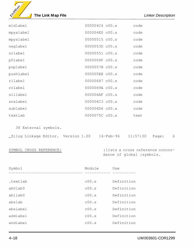
The Link Map File Linker Description
4–18 UM003601-COR1299
mldlabel 000004C4 c00.s code
mpyalabel 000004ED c00.s code
mpyslabel 00000515 c00.s code
neglabel 0000053D c00.s code
orlabel 00000551 c00.s code
p0label 0000006F c00.s code
poplabel 0000057B c00.s code
pushlabel 000005EE c00.s code
rllabel 00000687 c00.s code
rrlabel 0000069A c00.s code
slllabel 000006AF c00.s code
sralabel 000006C3 c00.s code
sublabel 000006D6 c00.s code
textlab 0000075C c00.s text
38 External symbols.
_Zilog Linkage Editor. Version 1.00 16-Feb-96 11:57:30 Page: 6
SYMBOL CROSS REFERENCE: ;lists a cross reference concor-dance of global ;symbols.
Symbol Module Use -------------------------------- ----------- ----------
.textlab c00.s Definition
ab0lab0 c00.s Definition
ab1lab0 c00.s Definition
abslab c00.s Definition
abslabel c00.s Definition
addlabel c00.s Definition
andlabel c00.s Definition

UM003601-COR1299 4–19
Linker Description The Link Map File
begin c00.s Definition
bs0lab1 c00.s Definition
bs0label c00.s Definition
bs1lab0 c00.s Definition
bs1lab1 c00.s Definition
bs1label c00.s Definition
calllabel c00.s Definition
codelab c00.s Definition
cplabel c00.s Definition
declabel c00.s Definition
firloop c00.s Definition
here c00.s Definition
inclabel c00.s Definition
jplabel c00.s Definition
label1 c00.s Definition
label2 c00.s Definition
ldlabel c00.s Definition
mldlabel c00.s Definition
mpyalabel c00.s Definition
mpyslabel c00.s Definition
neglabel c00.s Definition
orlabel c00.s Definition
p0label c00.s Definition
poplabel c00.s Definition
pushlabel c00.s Definition
rllabel c00.s Definition
rrlabel c00.s Definition
slllabel c00.s Definition
sralabel c00.s Definition
sublabel c00.s Definition

The Link Map File Linker Description
4–20 UM003601-COR1299
textlab c00.s Definition
ENTRY POINT: ;specifies the program entry point.
0069 Set from module 'c00.s'.
END OF LINK MAP: ;summarizes the status of the link. The number ;of error and warning messages are recorded in ;this section.
0 Warnings
0 Errors

UM003601-COR1299 4–21
Linker Description The Link Map File
Symbol File In Zilog Symbol Format A symbol file in the Zilog symbol format is generated when the user specifies the absolute link mode (-a linker option). It is in the standard Zilog symbol format as shown in Figure 5-3, which follows. In each row, the first column lists the symbol name, second column lists the attribute of the symbol (“I” stands for internal symbol, “N” stands for local symbol, and “X” stands for public symbol), and the third column provides the value of the symbol expressed as four hexadecimal bytes.
Figure 4-3. Sample Symbol File
_dgt_outbfr I 0000800d
_digit_cntr I 00008011
_dgt_inbfr I 00008012
_led_refresh I 000000b5
hex_reg N 00008009
_bcd_hex_convI fffff7f5
_7conv_reg_4 N 00008009
_8conv_reg_3 N 0000800a


UM003601-COR1299 A–1
ZILOG MACRO CROSS ASSEMBLER
APPENDIX A
DOS-VERSION ASSEMBLER AND LINKER
INVOKING THE ASSEMBLER
The syntax for the cross assembler command line is as follows:
ZMA [options] file
The assembler assembles the named file, which, by convention, ends with an .s suffix.
NOTES:
1. If no file is specified, an error message is written to the messages file, and the assemblerterminates without assembling anything.
2. If file is specified, but the assembler is unable to open it, an error message is written tomessages file, and the assembler terminates without assembling anything.
3. If file is specified, and the assembler can open it, but it is not a readable ASCII text file, anerror message is written to the messages file, and the assembler terminates withoutassembling anything.

Invoking the Assembler DOS-Version Assembler and Linker
A–2 UM003601-COR1299
Command Line OptionsCommand line options are specified by prefixing an option letter with a minus (-). The command line options are summarized in the following table.
Note:1. It is not required that options be specified alphabetically on the command line.2. Option letters other than those shown in the table are not legal. If any other option letter is used, an error
message is written to the messages file, and the assembler terminates without assembling anything.
Command Line Option -?The -? option requests that a product usage message be displayed on the standard output device.
Syntax: -?
Table A-1. Command Line Options
Option Interpretation
-? Requests a usage display.
-a Specifies absolute assembly mode.
-d Symbol [= Value ] Define a symbol, and optionally assign it a value.
-g Write source level debug information to the object module.
-I Directory Determines search path for INCLUDE instructions.
-l [ListFile] Produces an assembly listing.
-n Name Specifies the name that appears in the listing file header.
-o [ObjectFile] Produces an output object module.
-p Processor Specifies the target processor.
-q Quiet mode: suppress display of assembler copyright notice.
-t Produce a symbol table dump in the listing file.
-W Treat warnings as errors.
-w Suppresses warning message reporting.
-x Produces a cross reference in the listing file.
UM003601-COR1299 A–3
DOS-Version Assembler and Linker Invoking the Assembler
NOTES:
1. If the -? option is not specified, no product usage information is displayed.
2. If the -? option is specified, the assembler displays a product logo, including product versionnumber, and a brief description of the command line format and options. The informationis written to the standard output device.
3. This option may be specified only once on the command line. If the option is specified morethan once, an error message is written to the messages file, and the assembler terminateswithout assembling anything.
Command Line Option -aThe -a option controls the generation of an absolute object module. The default assembler behavior is to generate a relocatable object module, which must be post-processed by the linker. For certain small applications, it is appropriate to bypass the linker step, and have the assembler directly gen-erate an absolute load file, suitable for processing by a device programmer.
Syntax: -a
NOTES:
1. If the -a option is not specified, the assembler generates a relocatable object file.
2. If the -a option is specified, the assembler generates an absolute object file.
3. This option may be specified only once on the command line. If the option is specified morethan once, an error message is written to the messages file, and the assembler terminateswithout assembling anything.
Command Line Option -dThe -d option defines a symbol, and optionally assigns a value to the symbol.
Syntax: -d Symbol [ = Value ]
NOTES:
1. The -d option provides a method of defining, and assigning a value to a symbol. The optionis similar to the EQU assembler instruction. See ì REF _Ref349113646 \*MERGEFORMAT The EQU Assembler Instructionî on page PAGEREF _Ref34911365060.
2. If the optional Value is omitted, the symbol is defined to have a value of zero.
3. If the optional Value is sepcified, it must be separated from the Symbol by the literal tokendelimiter ë=í. Whitespace may surround the delimiter.
4. If the optional Value is specified, it may be a numeric or string constant.

Invoking the Assembler DOS-Version Assembler and Linker
A–4 UM003601-COR1299
Command Line Option -gThe -g option controls the automatic generation of symbolic debugging information in the ZOMF ob-ject module.
Syntax: -g
NOTES:
1. If the -g option is not specified, no symbolic debugging information is automatically writtento the object module.
2. If the -g option is specified, the assembler automatically writes line number and symboltable information to the object module. This information can be used by symbolicdebuggers, to allow the assembler language program to be debugged at the source modulelevel.
3. This option should be used only by assembler language programmers. C languageprogrammers should use the corresponding compiler option to generate symbolic debuginformation for C language programs.
4. This option may be specified only once on the command line. If the option is specified morethan once, an error message is written to the messages file, and the assembler terminateswithout assembling anything.
Command Line Option -IThe -I option specifies a directory to be searched for files specified with the INCLUDE assembler instruction.
Syntax: -I Directory
NOTES:
1. By default, all included files are assumed to exist in the current directory, or the directoryexplicitly specified on the INCLUDE assembler instruction.
2. The -I option, if specified, directs the assembler to look in the specified Directory forincluded files, if they cannot first be found in the current directory. The option only affectsthose INCLUDE instructions that specify only a filename to be included. It does not affectthose INCLUDE instructions that specify a path prefix on a filename.
3. Spaces or tabs may optionally separate the -I option letter and the Directory.
4. If the assembler cannot access the specified Directory, or if the Directory is not, in fact, adirectory, an error message is written to the messages file, and the assembler terminateswithout assembling anything.

UM003601-COR1299 A–5
DOS-Version Assembler and Linker Invoking the Assembler
5. The -I option may be specified up to sixteen times. If the option is specified more thansixteen times, an error message is written to the messages file, and the assemblerterminates without assembling anything.
6. If the -I option is specified more than once, the specified Directories must be unique. If thesame Directory is specified more than once, an error message is written to the messagesfile, and the assembler terminates without assembling anything.
7. If the -I option is specified more than once, the specified Directories are searched in theorder in which they appear on the command line (left to right), if the assembler cannot findincluded files in the current directory.
8. If the -I option is specified more than once, it is not required that the -I options arecontiguous.
9. It is not considered to be an error for the -I option to be specified when the assemblersource file does not contain any INCLUDE assembler instructions, nor when included filescan be found without reference to Directories specified with the -I option.
Command Line Option -lThe -l option controls the generation of an assembler listing file.
Syntax: -l [ListFile]
NOTES:
1. If the -l option is not specified, no listing file is produced.
2. If the -l option is specified, a listing file is produced.
3. If ListFile is specified, it must be a suffix of the -l option letter: no characters may intervenebetween -l and ListFile.
4. If ListFile is not specified, a default listing file name is formed, by replacing the suffixextension of the source file name with an extension of .lst. If the source file is standardinput, the formed listing file name is a.lst.
5. If ListFile is specified, it names the listing file, unless ListFile is the name of a directory, inwhich case the listing file is created in the directory specified by ListFile, and the listing filename is formed by replacing the suffix extension of the source file name with an extensionof .lst. If the source file is standard input, the formed listing file name is a.lst.
6. If the listing file cannot be opened, an error message is written to the messages file, andthe assembler terminates without assembling anything.

Invoking the Assembler DOS-Version Assembler and Linker
A–6 UM003601-COR1299
7. This option may be specified only once on the command line. If the option is specified morethan once, an error message is written to the messages file, and the assembler terminateswithout assembling anything.
Command Line Option -nThe -n option specifies the name that appears in the header of the assembler listing file. See ì REF _Ref340558564 \* MERGEFORMAT Assembler Listing Fileî on page PAGEREF _Ref340558565 114 for more details of the listing file format.
Syntax: -n Name
NOTES:
1. If the -n option is not specified, the assembler listing header contains the name of theassembler source file.
2. Spaces or tabs may optionally separate the -n option letter and the Name.
3. This option may be specified only once on the command line. If the option is specified morethan once, an error message is written to the messages file, and the assembler terminateswithout assembling anything.
Command Line Option -oThe -o option names the output object file.
Syntax: -o [ObjectFile]
NOTES:
1. If the -o option is not specified, no output object file is produced.
2. If the -o option is specified, an output object file is produced.
3. If ObjectFile is specified, it must be a proper suffix of the -o option letter: no characters mayintervene between the -o option letter and the ObjectFile.
4. If ObjectFile is not specified, a default object file name is formed, by replacing the suffixextension of the source file name with an extension of .o.
5. If ObjectFile is specified, it names the object file, unless ObjectFile is the name of adirectory, in which case the object file is created in the directory specified by ObjectFile, andthe object file name is formed by replacing the suffix extension of the source file name withan extension of .o.
6. If the object file cannot be opened, an error message is written to the messages file, andthe assembler terminates without assembling anything.

UM003601-COR1299 A–7
DOS-Version Assembler and Linker Invoking the Assembler
7. This option may be specified only once on the command line. If the option is specified morethan once, an error message is written to the messages file, and the assembler terminateswithout assembling anything.
Command Line Option -pThe -p option specifies the target processor for the assembly, that is, it controls which machine in-structions the assembler accepts as being valid. The assembler recognizes only those machine in-structions that are part of the instruction set(s) of the processor(s) defined by this option.
Syntax: -p Processor
NOTES:
1. If the -p option is not specified, the assembler assumes that the target processor is theZ89C00.
2. Spaces or tabs may optionally separate the -p option letter and the Processor.
3. The Processor must be one of those names shown in REF _Ref340464729 \*MERGEFORMAT Table 32 on page PAGEREF _Ref340464732 98. If Processor is notone such name, an error message is written to the messages file, and the assemblerterminates without assembling anything.
4. This option may be specified only once on the command line. If the option is specified morethan once, an error message is written to the messages file, and the assembler terminateswithout assembling anything.

Invoking the Assembler DOS-Version Assembler and Linker
A–8 UM003601-COR1299
Command Line Option -qThe -q (quiet) option suppresses display of the assembler copyright notice.
Syntax: -q
NOTES:
1. If the -q option is specified, the assembler copyright notice is not displayed.
2. If the -q option is not specified, an assembler copyright notice is written to the messagesfile.
3. This option may be specified only once on the command line. If the option is specified morethan once, an error message is written to the messages file, and the assembler terminateswithout assembling anything.
Command Line Option -tThe -t option controls the generation of an assembler symbol table list in the listing file.
Syntax: -t
NOTES:
1. If the -t option is not specified, no symbol table list is produced.
2. If the -t option is specified, a symbol table list is produced if a listing file is produced.
3. This option may be specified only once on the command line. If the option is specified morethan once, an error message is written to the messages file, and the assembler terminateswithout assembling anything.
Command Line Option -wThe -w option turns off warning message reporting.
Syntax: -w
NOTES:
1. If the -w option is specified, warning messages are not produced.
2. If the -w option is not specified, warning messages are written to the messages file, and tothe listing file (if one is being produced).
3. This option may be specified only once on the command line. If the option is specified morethan once, an error message is written to the messages file, and the assembler terminateswithout assembling anything.
UM003601-COR1299 A–9
DOS-Version Assembler and Linker Invoking the Assembler
Command Line Option -WThe -W option directs the assembler to treat warnings as errors.
Syntax: -W
NOTES:
1. If the -W option is specified, warning messages are treated as errors. That is, no output fileis generated by the assembler.
2. If the -W option is not specified, warning messages are not treated as errors.
3. If both -w and -W are specified, -w takes precedence.
4. This option may be specified only once on the command line. If the option is specified morethan once, an error message is written to the messages file, and the assembler terminateswithout assembling anything.
Command Line Option -xThe -x option controls the generation of an assembler cross reference list in the listing file.
Syntax: -x
NOTES:
1. If the -x option is not specified, no cross reference list is produced.
2. If the -x option is specified, a cross reference list is produced if a listing file is produced.
3. This option may be specified only once on the command line. If the option is specified morethan once, an error message is written to the messages file, and the assembler terminateswithout assembling anything.
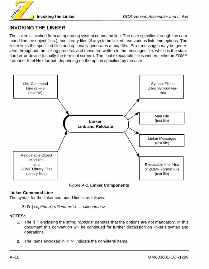
Invoking the Linker DOS-Version Assembler and Linker
A–10 UM003601-COR1299
INVOKING THE LINKER
The linker is invoked from an operating system command line. The user specifies through the com-mand line the object files.), and library files (if any) to be linked, and various link-time options. The linker links the specified files and optionally generates a map file. Error messages may be gener-ated throughout the linking process, and these are written to the messages file, which is the stan-dard error device (usually the terminal screen). The final executable file is written, either in ZOMF format or Intel Hex format, depending on the option specified by the user.
Figure A-1. Linker Components
Linker Command LineThe syntax for the linker command line is as follows:
ZLD [<options>] <filename1> ... <filenamen>
NOTES:
1. The “[ ]” enclosing the string “options” denotes that the options are not mandatory. In thisdocument this convention will be continued for further discussion on linker’s syntax andoperations.
2. The items enclosed in “< >” indicate the non-literal items.
LinkerLink and Relocate
Link CommandLine or File
(text file)
Relocatable Object Modules
andZOMF Library Files
(binary files)
Executable Intel Hex or ZOMF Format File
(text file)
Linker Messages (text file)
Map File (text file)
Symbol File in Zilog Symbol For-
mat

UM003601-COR1299 A–11
DOS-Version Assembler and Linker Invoking the Linker
3. The “. . .” (ellipses) indicate that multiple tokens can be specified. These tokens are of thetype of the non-literal specified in the syntax just prior to the ellipses.
4. The syntax uses “%” prefix to a number to specify a hexadecimal numeric representation.
5. The linker links the files listed in <filename> list. Each <filename> is the name of a ZOMFobject file or library file, or the name of a text file containing linker commands and options.
Command Line SpecificationsThe following rules govern the command line specification:
1. ZLD examines the named files’ content to determine the file type (object, library, or command).
2. The file names of the input files specified on the command line must be separated by spacesor tabs.
3. The commands are not case sensitive; however, command line options and symbol names arecase sensitive.
4. The order of specifying options does not matter.
5. The options must appear before the filenames.
Specifying that input files use both command line and list creates a union of the two sets of inputs that is treated as input object and library files. The linker links the file twice, if the file names appear twice.
During linking, the linker combines all object files in the order specified and resolves the external references. linker searches through the library files when it is unable to resolve references.
A command file is a text file containing linker commands and options. Comments can be specified by use of the “;” character.
1. If the linker is unable to open a named object file, library file, or a link command file, an errormessage is written to the standard error device, and the linker terminates without linkinganything.
2. If an unsupported OMF type of object file is included in the <filename> list, the linker displaysan error message and terminates without linking anything.

Invoking the Linker DOS-Version Assembler and Linker
A–12 UM003601-COR1299
Linker OptionsLinker options are specified by prefixing an option word with a minus (-). The linker options are sum-marized in Table 5-2.
3. The options are listed alphabetically in the table, for convenience.4. It is not required that options be specified alphabetically on the command line.5. If any other option word is used, an error message is written to the messages file, and the linker termi-
nates without linking anything.6. All options must be preceded by a dash (-).
Table A-2. Summary of Linker Options
Options Description
-? Displays product logo, version number, and brief description of command line format and options.
-a Generates an absolute object file in Intel Hex Format or Zilog Symbol Format.
-e <entry> Specifies the program entry point. <entry> is any Public symbol.
-g Generates symbolic debug information.
-m <mapfile> Generates the map file.
-o <objectfile> Generates the output file.
-q Disables display of linker’s copyright notice.
-W Treats warnings as errors.
-w Disables the generation of warning messages.

UM003601-COR1299 A–13
DOS-Version Assembler and Linker Invoking the Linker
Linker CommandsThe linker commands are summarized in Table X-X. The section that follows describes each com-mand and provides an example of its use. The linker commands must be placed in a link command file.
1. The linker commands are listed alphabetically in the table, for convenience; however, it is not requiredthat commands be specified alphabetically in the command file.
2. Command words and parameters other than those shown in the table are not legal. If any other word orparameter is used, an error message is written to the messages file, and the linker terminates withoutlinking anything.
Linker Command ASSIGNThe ASSIGN command assigns a control section to an address space. This command is designed to be used in conjunction with the assembler’s .SECT instruction.
Syntax: ASSIGN <section> <address-space>
The <section> must be a control section name, and the <address-space> must be an ad-dress space name.
Example: ASSIGN DSEG DATA
Linker Command COPYThis command makes a copy of a control section. The control section is loaded at the specified location, rather than at its linker-determined location. This command is designed to make a copy of an initialized RAM data section in a ROM address space, so that the RAM may be initialized from the ROM at run time.
Table A-3. Summary of Linker Commands
Command Description
Assign Assigns a control section to an address space.
Copy Makes a copy of a control section.
Define Creates a public symbol at link-time; helps resolve an external symbol referenced at assembly time.
Order Specifies the ordering of specified control sections.
Range Sets a lower bound and an upper bound for an address space or a control section.

Invoking the Linker DOS-Version Assembler and Linker
A–14 UM003601-COR1299
Syntax: COPY <section> <address-space> [ AT <expression> ]
The <section> must be a control section name, and the <address-space> must be an ad-dress space name. The optional AT <expression> is used to copy the control section to a specific address in the target address space.
Example: COPY bank1_data ROM or COPY bank1_data ROM at %1000
Linker Command ORDERThis command determines a sequence of linking.
Syntax: ORDER <name1> [,<name2> ...]
<namen> must be a control section name.
Example: ORDER CODE1, CODE2
Linker Command RANGEThis command sets the lower and upper limits of a control section or an address space. The linker issues a warning message if an address falls beyond the range declared with this command.
The linker provides multiple ways for the user to apply this command for a link session. Each sep-arate case of the possible syntax is described below.
Syntax :
(case i)
RANGE <name> <expression> , <length> [ , ... ]
<name> may be a control section, or an address space. The first <expression> indicates the lower bound for the given address RANGE. The <length> is the length, in words, of the object.
Example: RANGE ROM %700 , %100
(case ii)
RANGE <name> <expression> : <expression> [ , ... ]
<name> may be a control section or an address space. The first <expression> indicates the lower bound for the given address RANGE. The second <expression> is the upper bound for it.
Example: RANGE ROM %17ff : %2000
NOTE: Refer to the Expression Formats for the format of writing an expression.
UM003601-COR1299 A–15
DOS-Version Assembler and Linker Invoking the Linker
Linker Command DEFINE This command is used for a link-time creation of a user defined public symbol. It helps in resolving any external references (EXTERN) used in assembly time.
Syntax: DEFINE <symbol name> = <expression>
<symbol name> is the name of the public symbol. <expression> is the value of the public symbol.
Example: DEFINE copy_size = copy top of usr_seg - copy base of usr_seg
NOTE: The “Expression Formats” section, which follows, explains different types of expressionsthat can be used.

Invoking the Linker DOS-Version Assembler and Linker
A–16 UM003601-COR1299
Expression FormatsThe following section describes the operators and their operands that form legal linker expressions.
<expresson>Defined as any valid assembler expression
BASE OF OperatorThe BASE OF operator provides the lowest used address of an address space or control section. (This does not include any control section copies if the <name> is a control section).
Syntax: BASE OF <name>
<name> must be an address space or control section name.
COPY BASE OF OperatorThe COPY BASE OF operator provides the lowest used address of a copy control section.
Syntax: COPY BASE OF <name>
<name> must be a control section name.
COPY TOP OF OperatorThe COPY TOP OF operator provides the highest used address of a copy control section.
Syntax: COPY TOP OF <name>
<name> is a control section name.
FREEMEM OF OperatorThe FREEMEM OF operator provides the lowest address of an unallocated memory of a control section or address space.
Syntax: FREEMEM OF <name>
<name> may be a control section or address space name.
HIGHADDR OF OperatorThe HIGHADDR OF operator provides the uppermost allocated address of an address space or control section (except for any control section copies when <name> is a control section).
Syntax: HIGHADDR OF <name>
<name> is an address space or control section.
LENGTH OF OperatorThe LENGTH OF operator provides the length of a control section or address space.

UM003601-COR1299 A–17
DOS-Version Assembler and Linker Invoking the Linker
Syntax: LENGTH OF <name>
<name> must be an address space or control section name.
LOWADDR OF OperatorThe LOWADDR OF operator provides the lowest possible address of a control section or address space.
Syntax: LOWADDR OF <name>
<name> must be an address space or control section name.

Invoking the Linker DOS-Version Assembler and Linker
A–18 UM003601-COR1299
TOP OF OperatorThe TOP OF operator provides the highest possible address of an unallocated memory of a control section or address space.
Syntax: TOP OF <name>
<name> must be a control section or address space name.
+ (Addition) OperatorPerforms addition of two expressions.
Syntax: <expression> + <expression>
& (Anding) OperatorPerforms bitwise & of two expressions.
Syntax: <expression> & <expression>
/(Division) OperatorPerforms division.
Syntax: <expression> / <expression>
* (Multiplication) OperatorPerforms multiplication of two expressions.
Syntax: <expression> * <expression>
% (Modulus) OperatorPerforms modulus of two expressions.
Syntax: <expression> % <expression>
Decimal Numeric Value ExpressionsUsed as expressions or parts of expressions.
Syntax: <digits>
The <digits> are collections of numeric digits from 0 to 9.
Hexadecimal Numeric Value ExpressionsUsed as expressions or parts of expressions.
Syntax: %<hexdigits>
The <hexdigits> are collections of numeric digits from 0 to 9 or A to F.
UM003601-COR1299 A–19
DOS-Version Assembler and Linker Invoking the Linker
| (Or logic) OperatorBitwise inclusive | (Or) of two expressions.
Syntax: <expression> | <expression>
Invoking the Linker DOS-Version Assembler and Linker
A–20 UM003601-COR1299
<< (Left Shift) OperatorLogical left shift.
Syntax: <expression> << <expression>
The <expression> to the left of << is the value that is shifted to the left, determined by the <expression> value to the right of <<.
>> (Right Shift) OperatorPerforms a right shift.
Syntax: <expression> >> <expression>
The <expression> to the right of << is the value that is shifted to the right, determined by the <expression> value to the left of <<.
-(Subtraction) OperatorSubtracts two expressions.
Syntax: <expression> - <expression>
^(Bitwise Exclusive OR logic) OperatorPerforms a bitwise Exclusive OR on two expressions.
Syntax: <expression> ^ <expression>
~(Invert) OperatorDoes a one’s complement of an expression.
Syntax: ~ <expression>
UM003601-COR1299 B–1
ZILOG MACRO CROSS ASSEMBLER
APPENDIX B
UTILITIES DESCRIPTION
ZFIXUP
The ZFIXUP utility is a simple DOS-based program that does ‘address fixups’ on assembly lan-guage listing files generated by relocatable assemblers such as ZMASM. The normal listing file con-tains relative addresses (base zero) only, since the final execution address is not determined until after linking all such relocatable files is done. ZFIXUP interrogates the link map file to determine the final execution addresses and then modifies the listing files to insert this information, thus ‘fixing’ the file for easier debugging. ZFIXUP only fixes the program counter addresses. It makes no at-tempt to fix the machine code fields (operands).
Syntax:
ZFIXUP <mapfile> [<srcfile> ...]
where:
<mapfile>The name of the link map file for which address fixups are to be performed. Compatible with link map files produced by Zilog's ZMASM assembler and with Production Languages Corp. (PLC) assemblers. The default assumed filename suffix is .MAP.
<srcfile>The names of specific listing files for which address fixups are desired. Separate multiple filenames by spaces. If none are specified, then all files will have address fixups done. Filename suffixes are not required.
Examples:
c:>zasmlist ;invoked without any parameters
zasmlist Version X.XX. Copyright (C) Zilog Inc. 1995
usage: zasmlist <mapfile> [<srcfile> ...]
ZFIXUP Utilities Description
B–2 UM003601-COR1299
c:>zasmlist xxxx ;invoked with non-existent file XXXX
zasmlist Version X.XX. Copyright (C) Zilog Inc. 1995
usage: zasmlist <mapfile> [<srcfile> ...]
Cannot access input map file xxxx.map
c:>zasmlist project ;invoked with map file PROJECT.MAP to fixup all files
c:>zasmlist project start main ;invoked with map file PROJECT.MAP to fixup only
;listing files for modules START and MAIN
UM003601-COR1299 B–3
Utilities Description ZFIXUP
ZCONVERTThe ZCONVERT utility is a Windows-based program that manipulates object files. It can convert object files from one format into another, split, merge, and also compare object files. These func-tions are useful when burning object code into EPROMs or when verifying a ROM code submission to or from Zilog when ordering mask ROM parts.
The supported object file formats are as follows:
Zilog ROM Report
Intel Hex (Byte) Format
Intel Hex (Word) Format
Tektronix Hex (Byte) Format
Tektronix Hex (Word) Format
Binary Format
Upon invocation, an empty window box is presented with the following menu options:
File Menu CommandsConvert Converts files from one format to another.
Split Splits files into two files, one containing the high byte and the other containing the low byte. Opposite of Merge.
Merge Merges two files, one containing the high byte and the other containing the low byte. Opposite of Split.
Compare Compares two files.
Exit Exits the program.
Help Menu CommandsIndex Indexes into the ZCONVERT help system.
Using Help Explains using the on-line help system.
About Zconvert Displays the version number and copyright information.

ZFIXUP Utilities Description
B–4 UM003601-COR1299
The user selects the desired operation from the File Menu and follows the indicated simple dialog instructions or consults the on-line Help system for assistance.

UM003601-COR1299 B–5
Utilities Description ZFIXUP
ZDUMPThe ZDUMP utility serves two purposes. The first is as a simple filter utility to generate an Intel hex object file and/or a standard Zilog symbol file without using the linker. The second is as a diagnostic utility for analysis by Zilog when problems are encountered. When problems are reported to Zilog, the user may be instructed to use ZDUMP to help analyze the problem to determine where the fault may be, since an assembler with linker is a complicated tool chain. The option letters are case sen-sitive.
Syntax:
ZDUMP [-?] [-d] [-i] [-s] <object>
where:
? Generates a simple ‘help’ output of the program name, version, and avail-able options. Also generates this by default for any erroneous invocation.
d Dump the object file in human readable format to the standard output stream (for Factory analysis). The output is readable ASCII text.
i Generate Intel hex format object file. The output file is automatically gener-ated using the name of the <object> file and the proper suffix type is ap-pended; ‘HEX’ for byte, ‘IHX’ for word, ‘PGM’ for Program Space, and ‘DAT’ for Data Space.
s Generate a standard Zilog symbol file. The output file is automatically gen-erated using the name of the <object> file and the ‘SYM’ suffix type is ap-pended
<object> This is the ZMASM produced object file to be used as the input to ZDUMP. It can be an assembler output file (*.O) or a linker output file (*.LD).
Examples:
c:>zdump ;invoked without any parameters
Zilog Object Dumper Version XX.XX.
Copyright 1996 Zilog Inc.
No object file specified.

ZFIXUP Utilities Description
B–6 UM003601-COR1299
Usage: ZDUMP [-?] [-d] [-i] [-s] <object>
c:>zdump xxxx ;invoked with non-existent file XXXX
Zilog Object Dumper Version XX.XX.
Copyright 1996 Zilog Inc.
Cannot open 'xxxx'
Usage: ZDUMP [-?] [-d] [-i] [-s] <object>
c:>zdump -d modem.o ;invoked with non-ZMASM file MODEM.O
Zilog Object Dumper Version XX.XX.
Copyright 1996 Zilog Inc.
Input file is not in ZOMF format.
Usage: ZDUMP [-?] [-d] [-i] [-s] <object>
c:>zdump -d project.o >project.i ;generates debug dump file PROJECT.I
;from PROJECT.O assembler output
;file for Zilog problem analysis
c:>zdump -i -s project.ld ;generates Intel hex file PROJECT.HEX
;and symbol file PROJECT.SYM

UM003601-COR1299 C–1
ZILOG MACRO CROSS ASSEMBLER
APPENDIX C
ASSEMBLER AND LINKER ERROR
MESSAGES
ASSEMBLER ERRORS
There are three basic types of assembler errors in ZMASM. They are 1) Error, 2) Warning, 3) Fatal. The format of these error messages is as shown below. ZMA is used to denote an assembler error, while ZLD is used to denote a linker error. Errors are items that must be corrected, but the assem-bling process will continue. Warnings are items that should be investigated to determine that no harm is being done, and the assembling process will continue. Fatal errors are absolute catastroph-ic problems that must be corrected and the assembling process is aborted.
<filename>: line nnnn: ZMA-Ennnn Error: <text><filename>: line nnnn: ZMA-Wnnnn Warning: <text>ZMA-Fnnnn Fatal: <text>
The <text> messages are shown below. To find your error message, locate the matching Ennnn, Wnnnn, or Fnnnn number as listed. The first section following is a brief description of the error while the second gives useful hints on how to remedy the error.
When reporting a possible error to Zilog per the Error Reporting Appendix, be sure to note the fol-lowing items.
1. Host Operating System and version number.
2. Host computer type (like IBM, Compaq, and Toshiba).
3. Host computer memory size.
4. ZMASM release number plus version numbers of ZMA and ZLD.
5. Condense the problem into the smallest example possible that highlights the error. Be preparedto send your files to Zilog if requested.
NOTES:
1. %s = string substitution of actual message

assembler errors Assembler and Linker Error Messages
C–2 UM003601-COR1299
2. %d = decimal value substitution
3. %lf = long floating-point value substitution
4. %c = single character value substitution
E0000: Internal assembler error detected
An unexpected internal error in ZMA has been encountered.
Record the exact sequence leading to the error and file an error report per the Error ReportingAppendix.
E0001: %s
A special, miscellaneous error has been encountered.
Read the message carefully and respond accordingly. If the problem persists or assistance isrequired, record the exact sequence leading to the error and file an error report per the ErrorReporting Appendix.
E0002: Too many assembly errors
An excessive number of errors was encountered making further assembly useless.
Examine each individual error, consult the User’s Manual, and correct as appropriate. Be surethe correct MCU target processor is selected and all necessary EQU and MACRO files areINCLUDE’d.
E0003: Warning treated as an error: no object file generated
ZMA has encountered a Warning that was directed to be treated as an error, thereby causingthe assembly to fail.
Examine the warning, consult the User’s Manual, and correct as appropriate. Or change theassembler options to ignore warnings, being careful that this warning does not cause incorrectcode generation to occur.
E0004: Phase error between passes
A label value has changed between pass one and pass two evaluation of the source code dueto a different number of bytes being allocated for each pass.
Move all variable definitions (EQUs) to the beginning of each file. Closely check all codebetween the error location and the immediate prior symbol occurrence to determine why thegenerated bytes would be different between pass one and two. Add dummy label names

UM003601-COR1299 C–3
Assembler and Linker Error Messages assembler errors
(“Lxxx”) to each such line and reassemble if the cause is not obvious to determine which line iscausing the problem.
E0005: Syntax error
An error in the accepted syntax has been detected.
Consult the User’s Manual for the defined syntax per the type of error detected and correct asrequired. If the problem persists or assistance is required, record the exact sequence leadingto the error and file an error report per the Error Reporting Appendix. Sometimes, the root causeof a syntax error can be caused by the preceding line(s).
E0006: Token contains too many characters
A source statement token contains too many characters. As the assembler reads a sourceprogram, it breaks the input lines into “tokens,” each of which represents a label, symbolicname, operator, or other punctuation. One such token contains too many characters.
Make sure that each token in the input source file contains no more that 512 characters. Thiserror can also be caused by macro expansion.
E0007: Instruction unsupported by current processor
The instruction (opcode) specified is invalid for the specified target processor.
Consult the specified target processor’s instruction manual to determine the appropriate validinstruction type(s) required as replacements. Ensure that the correct target processor has beenselected via the CHIP and TARGET directives.
E0008: Processor type conflicts with current processor
The microcontroller specified in the CHIP directive conflicts with the selected target for thecurrent project.
Make sure that the target microcontroller selected as the project target does not conflict withthe microcontroller specified in the CHIP directive.
E0009: This instruction requires a label
The instruction (opcode) specified requires a label for proper operation.
Consult the instruction’s definition and add the appropriate label. Or chose another instruction.

assembler errors Assembler and Linker Error Messages
C–4 UM003601-COR1299
E0010: Multiple labels are not permitted
More than one label has been detected on the source line.
Remove the extra label(s) as appropriate. An extraneous colon character (:) may be causingan extra label to be detected.
E0011: Label '%s' is already defined
The specified label already exists in the symbol table.
Use an editor to find the prior label (it could be in an INCLUDE file) with the same spelling, thendecide which one to alter. This error can sometimes be caused by mis-typing a label or byconfusion between the letter oh (O) and the number zero (0). It should also be noted that upperand lower case letters for symbols are distinct, that is, they are not identical.
E0012: Symbol '%s' is not defined
The specified symbol does not exist in the symbol table.
The symbol definition statement is missing or the symbol has been misspelled. Carefullyexamine the source code and correct as required. It should also be noted that upper and lowercase letters for symbols are distinct, that is, they are not identical.
E0013: Symbol '%s' is not defined or is forward referenced
The specified symbol does not exist in the symbol table or it is defined after this source linereferences it.
The symbol definition statement is missing or must be moved in front of the current statement.A misspelled symbol can also cause this error. It should also be noted that upper and lowercase letters for symbols are distinct, that is, they are not identical.
E0014: Forward referenced equate must be an absolute expression
A symbol defined using the EQU directive uses a label that is defined later on in the sourcecode.
Make sure that all labels used in an EQU expression are defined before the EQU directive isused.

UM003601-COR1299 C–5
Assembler and Linker Error Messages assembler errors
E0015: Illegal use of external symbol
The external symbol is being referenced in an illegal manner, such as illegal combination of anexpression.
Consult the User Manual for the rules in using an external symbol, including the rules forexpressions.
E0016: Illegal use of external symbol
The external symbol is being referenced in an illegal manner, such as illegal combination of anexpression.
Consult the User Manual for the rules in using an external symbol, including the rules forexpressions. This error is identical to the previous one, except it occurs at a different internalparsing point.
E0017: Illegal use of symbol '%s'
The named symbol is being referenced in an illegal manner.
Consult the User’s Manual for the definition of the entry in the operation (opcode) field todetermine the offending usage and correct as necessary. Also, consult the section onexpressions.
E0018: Symbol '%s' already declared external
The specified label has previously been defined as external.
Use an editor to find the prior external declaration of the named symbol (it could be in anINCLUDE file) with the same spelling, then decide which one to delete. This error cansometimes be caused by mis-typing a symbol or by confusion between the letter oh (O) and thenumber zero (0). It should also be noted that upper and lower case letters for symbols aredistinct, that is, they are not identical.
E0019: Local symbol '%s' can't be made public
The specified symbol is not permitted to have global scope, that is, it cannot be made known toother source modules.
Change the local symbol to a normal symbol or remove the symbol from the Public directive.
E0020: Label '%s' is not a formal macro parameter name
The specified label was not found as a formal macro parameter name.
Make sure that the specified label is the name of a macro parameter.

assembler errors Assembler and Linker Error Messages
C–6 UM003601-COR1299
E0021: Parameter '%s' is multiply defined
The macro parameter specified has already been defined.
Use an editor to find the prior parameter definition with the same spelling, then decide whichone to alter. This error can sometimes be caused by mis-typing a label or by confusion betweenthe letter oh (O) and the number zero (0). It should also be noted that upper and lower caseletters for symbols are distinct, that is, they are not identical.
E0022: Unbalanced macro definition header
The number of MACRO and MACEND directives does not match.
Check the occurrences of each MACRO and matching MACEND to determine the cause of themismatch and correct as appropriate. Macro definitions must be completely defined within onesource file.
E0023: Unbalanced macro definition trailer
The number of MACRO and MACEND directives does not match.
Check the occurrences of each MACRO and matching MACEND to determine the cause of themismatch and correct as appropriate. Macro definitions must be completely defined within onesource file.
E0024: Macro trailer name '%s' does not match macro header name '%s'
The name specified on the MACEND directive does not match the name specified on theMACRO instruction.
If a name is specified on the MACEND directive, make sure that it is the same as the name onthe corresponding MACRO directive.
E0025: Unbalanced structured assembly test primary
A structured assembly test primary directive (.$IF, .$REPEAT, .$WHILE) has a mismatchbetween it and it’s corresponding ending directive.
Carefully check the matching beginning and ending structured assembly directives formatching pairs.
UM003601-COR1299 C–7
Assembler and Linker Error Messages assembler errors
E0026: Unbalanced structured assembly test alternate
The structured assembly test alternate directive (.$ELSEIF) has a mismatch between it and it’scorresponding ending directive.
Carefully check the matching beginning and ending structured assembly directives formatching pairs.
E0027: Unbalanced structured assembly test default
The structured assembly test default directive (.$ELSE) has a mismatch between it and it’scorresponding ending directive.
Carefully check the matching beginning and ending structured assembly directives formatching pairs.
E0028: Unbalanced structured assembly loop control
A structured assembly test primary directive (.$REPEAT, .$WHILE) has a mismatch betweenit and it’s corresponding ending directive.
Carefully check the matching beginning and ending structured assembly directives formatching pairs.
E0029: Unbalanced structured assembly end
An unexpected structured assembly end directive (.$ENDIF, .$UNTIL, .$WEND) wasencountered.
Carefully check the matching beginning and ending structured assembly directives formatching pairs.
E0030: Unbalanced structured assembly end
An unexpected structured assembly end directive (.$ENDIF, .$UNTIL, .$WEND) wasencountered.
Carefully check the matching beginning and ending structured assembly directives formatching pairs.
E0031: Unbalanced structured assembly end
An unexpected structured assembly end directive (.$ENDIF, .$UNTIL, .$WEND) wasencountered.
Carefully check the matching beginning and ending structured assembly directives formatching pairs.
assembler errors Assembler and Linker Error Messages
C–8 UM003601-COR1299
E0032: Unbalanced conditional assembly test primary
A conditional assembly test primary directive (.IF, .IFDEF, .IFNDEF, .IFEQ, .IFEQI, .IFNEQ,.IFNEQI, .IFB, .IFNB) has a mismatch between it and it’s corresponding ending directive.
Carefully check the matching beginning and ending structured assembly directives formatching pairs.
E0033: Unbalanced conditional assembly test alternate
The conditional assembly test alternate directive (.ELSEIF) has a mismatch between it and it’scorresponding ending directive.
Carefully check the matching beginning and ending structured assembly directives formatching pairs.
E0034: Unbalanced conditional assembly test default
The conditional assembly test default directive (.ELSE) has a mismatch between it and it’scorresponding ending directive.
Carefully check the matching beginning and ending structured assembly directives formatching pairs.
E0035: Unbalanced conditional assembly end
An unexpected structured assembly end directive (.ENDIF) was encountered.
Carefully check the matching beginning and ending structured assembly directives formatching pairs.
E0036: Alternate test must appear before default test
The conditional assembly test alternate (.ELSEIF) was encountered after the default testdirective (.ELSE).
Review the conditional assembly as written against the condition assembly section of the usermanual and restructure to comply with the valid syntax.
E0037: Alternate test must appear before default test
The conditional assembly test alternate (.ELSEIF) was encountered after the default testdirective (.ELSE).
Review the conditional assembly as written against the condition assembly section of the usermanual and restructure to comply with the valid syntax.
UM003601-COR1299 C–9
Assembler and Linker Error Messages assembler errors
E0038: Multiple test defaults are not allowed
More than one conditional assembly test default (.ELSE) was encountered.
Review the conditional assembly as written against the condition assembly section of the usermanual and restructure to comply with the valid syntax.
E0039: Multiple test defaults are not allowed
More than one conditional assembly test default (.ELSE) was encountered.
Review the conditional assembly as written against the condition assembly section of the usermanual and restructure to comply with the valid syntax.
E0040: Too many actual macro parameters
The number of actual macro parameters in this macro call exceed the number of formalparameters defined in the macro header definition.
Review the macro call parameters versus the macro definition header formal parameters andchange as appropriate.
E0041: Macro recursion limit exceeded
The recursion limit for macros (calling itself) has been exceeded.
Carefully examine the source code to determine why a macro is calling itself an excessivenumber of times. This is usually caused by simple typing error or a source coding mistake(missing source line). If the source code is correct and a higher level of macro recursion isrequired, then the recursion limit must be increased by using the MACCNTR directive.
E0042: Instruction illegal in open code
The specified instruction is not permitted in open code, that is, it must be used inside specialcode such as conditionals, macros, or structured assembly.
Remove the instruction or recode properly.
E0043: Unrecognized instruction mnemonic
The instruction mnemonic (opcode) is unknown to ZMA.
Carefully check the spelling of the instruction mnemonic versus those specified for ZMA andcorrect as required.

assembler errors Assembler and Linker Error Messages
C–10 UM003601-COR1299
E0044: Invalid operand
The operand field contains an error.
Carefully check the operand field versus the valid operands for the instruction specified (asdefined for ZMA) and correct as required.
E0045: Invalid character escape sequence
The character following the escape character (\) is not recognized by ZMA.
Consult the character constant and string constant escape sequence tables defined for ZMAand correct as required.
E0046: Include nesting limit exceeded
The source code stream has too many successive INCLUDE directives which has resulted intoo many files being open at the same time.
Reorganize the source code to reduce the number of files open at one time by carefullyexamining usage of the INCLUDE directive.
E0047: Recursive inclusion of file '%s'
The INCLUDE directive has specified the same filename as the currently open file.
Change the filename or delete the erroneous INCLUDE statement.
E0048: File name contains too many characters
The allowable number of characters for a filename has been exceeded.
Change the filename to be within the allowable number of characters.
E0049: Cannot open file '%s'
The host operating system encountered an error in opening the filename specified.
The specified file is missing or damaged, or insufficient disk space is available. Check for theseconditions and correct as necessary. A missing ZMASM file can be restored by re-installingZMA from the distribution media. A missing user file must be restored by the user from theirbackup or archival media. A damaged file or file system can be repaired by running the systemutility CHECKDISK, SCANDISK, or other similar file system integrity checking utility. A writeprotected media or a typing error can also cause this error. Change the filename to an existingfile or create the specified filename. If a partial file path was included in the filename, ensurethat the path is valid.
UM003601-COR1299 C–11
Assembler and Linker Error Messages assembler errors
E0050: '%s' is not a known processor name
The specified entry is not a processor name recognized by ZMA.
Change the specified entry to a valid processor name for the CPU directive.
E0051: '%s' is not a known target name
The specified entry is not a target name recognized by ZMA.
Change the specified entry to a valid target name for the TARGET directive.
E0052: Invalid bank specification
The DSP memory bank specified is invalid for this instruction.
Consult the instruction description and correct as required.
E0053: Invalid addressing mode
The addressing mode specified for this instruction is not legal.
Consult the instruction description and correct as required.
E0054: Illegal expression type for address operand
The expression type for the addressing operand for this instruction is not legal.
Consult the instruction description and correct as required.
E0055: Relocatable address expression out of range
The relocatable address expression exceeds the permissible range.
Consult the instruction description and correct as required.
E0056: Illegal relocatable expression operation
The relocatable expression operation is not permitted.
Consult the instruction description and the section on relocatable assembly expressions. Thencorrect as required.
E0057: '%s' address space illegal for this instruction
The address space specified is not permitted for this instruction.
Consult the instruction description and correct as required.
assembler errors Assembler and Linker Error Messages
C–12 UM003601-COR1299
E0058: Radix suffix conflicts with preceding digits
The radix suffix specified is not compatible with the preceding digits.
Each number base radix suffix dictates the permissible character set for that numbering base.This error message indicates a mismatch has occurred, such as specifying binary (B suffix) buthaving a preceding digit not consisting of only zeros and ones (such as 2-9). It can also becaused by failure to append the radix suffix, as in “37A0”. The missing hexadecimal radix suffix(H) caused the error. Correct as appropriate.
E0059: Operand out of range
The operand exceeds the permissible range for the specified instruction.
Consult the instruction description and correct as required.
E0060: Effective address operand out of range
The effective address of the operand exceeds the permissible range for the specifiedinstruction.
Consult the instruction description and correct as required.
E0061: Register pair must be at even address
The specified register pair can only begin at an even address.
The register pair starting address must begin at an address divisible by two. Correct asappropriate.
E0062: This instruction may be used once only
The specified instruction is only permitted a single time.
Some instructions such as VECTOR, by their nature, can only be used once in the assembly.Consult the instruction description and correct as required.
E0063: This instruction may not appear after a VECTOR instruction
The specified instruction is only permitted a single time.
By their nature, some instructions (CPU, TARGET, VECTOR) can only be used once in anassembly. Consult the instruction description and correct as required.

UM003601-COR1299 C–13
Assembler and Linker Error Messages assembler errors
E0064: Division by zero
The expression evaluator has detected an illegal attempt to divide by zero.
Because division by zero cannot be handled (result is infinity), an error message must be given.If the cause is not obvious due to a complicated expression, break the expression into multiplesubstatements using the EQU directive to determine the cause of the error. Then correct asrequired.
E0065: Shift count is out of range
The specified shift count exceeds the permissible range.
Consult the instruction description and correct as required.
E0066: Exponentiation requires a positive power
The specified exponent has a negative value.
Carefully check the exponentiation expression to determine why it is negative. If the cause isnot obvious due to a complicated expression, break the expression into multiple substatementsusing the EQU directive to determine the cause of the error. Then correct as required.
E0067: Modulus requires integral operands
The modulus operator only accepts integral operands.
Carefully examine the modulus expression to determine why a non-integral operand occurs andcorrect as required. If the cause is not obvious due to a complicated expression, break theexpression into multiple substatements using the EQU directive to determine the cause of theerror. Then correct as required.
E0068: Null in string
The null character (\0) was detected in a string constant.
The null character is only legal in character constants, that is, inside single quote (‘) marks.Double quote marks denote string constants.
E0069: Fixed-point number '%lf' is out of range [-1.0,1.0)
The specified fixed-point number exceeds the permissible range.
Consult the fixed-point number description under the Assembler Constants section and correctas required.

assembler errors Assembler and Linker Error Messages
C–14 UM003601-COR1299
E0070: Floating-point constant overflow
The specified floating-point constant exceeds the permissible range.
Consult the floating-point constant description under the Assembler Constants section andcorrect as required.
E0071: Integral constant overflow
The specified integral constant exceeds the permissible range.
Consult the integral constant description under the Assembler Constants section and correctas required.
E0072: Expected a machine, assembler, or macro call instruction
The syntax evaluation required a machine, assembler, or macro call instruction.
Consult the Source Statement Format and specific instruction description. Then correct asrequired.
E0073: Expected a hardware register operand
The syntax evaluation required a hardware register operand.
Consult the specific instruction description and correct as required.
E0074: Expected a hardware register or condition code
The syntax evaluation required a hardware register or condition code.
Consult the specific instruction description and correct as required.
E0075: Expected a register pair specification
The syntax evaluation required a register pair specification.
Consult the specific instruction description and correct as required.
E0076: Expected a working register pair specification
The syntax evaluation required a working register pair specification.
Consult the specific instruction description and correct as required.

UM003601-COR1299 C–15
Assembler and Linker Error Messages assembler errors
E0077: Expected an indirect working register pair specification
The syntax evaluation required an indirect working register pair specification.
Consult the specific instruction description and correct as required.
E0078: Expected a register specification
The syntax evaluation required a register specification.
Consult the specific instruction description and correct as required.
E0079: Expected a working register specification
The syntax evaluation required a working register specification.
Consult the specific instruction description and correct as required.
E0080: Expected an indirect working register specification
The syntax evaluation required an indirect working register specification.
Consult the specific instruction description and correct as required.
E0081: Expected hardware register A operand
The syntax evaluation required a hardware register A operand.
Consult the specific instruction description and correct as required.
E0082: Expected a pointer register operand
The syntax evaluation required a pointer register operand.
Consult the specific instruction description and correct as required.
E0083: Expected immediate address mode
The syntax evaluation required an immediate address mode.
Consult the specific instruction description and correct as required.
E0084: Expected a colon (:)
The syntax evaluation required a colon (:) character.
Consult the specific instruction description and correct as required.

assembler errors Assembler and Linker Error Messages
C–16 UM003601-COR1299
E0085: Expected a comma (,)
The syntax evaluation required a comma (,) character.
Consult the specific instruction description and correct as required.
E0086: Expected an assignment (=)
The syntax evaluation required an equal (=) character.
Consult the specific instruction description and correct as required.
E0087: Expected a single quote (')
The syntax evaluation required a single quote (‘) character.
Consult the specific instruction description and correct as required.
E0088: Expected a double quote (")
The syntax evaluation required a double quote (“) character.
Consult the specific instruction description and correct as required.
E0089: Expected a left parenthesis
The syntax evaluation required a left parenthesis [(] character.
Consult the specific instruction description and correct as required.
E0090: Expected a right parenthesis
The syntax evaluation required a right parenthesis [)] character.
Consult the specific instruction description and correct as required.
E0091: Expected a right bracket
The syntax evaluation required a right bracket (]) character.
Consult the specific instruction description and correct as required.
E0092: Expected a LOOP modifier
The syntax evaluation required a LOOP modifier.
Consult the specific instruction description and correct as required.

UM003601-COR1299 C–17
Assembler and Linker Error Messages assembler errors
E0093: Expected a bank switch modifier (ON or OFF)
The syntax evaluation required a bank switch modifier.
Consult the specific instruction description and correct as required.
E0094: Expected a fixed-point expression
The syntax evaluation required a fixed-point expression.
Consult the specific instruction description and correct as required.
E0095: Expected a floating-point expression
The syntax evaluation required a floating-point expression.
Consult the specific instruction description and correct as required.
E0096: Expected an absolute integer expression
The syntax evaluation required an absolute integer expression.
Consult the specific instruction description and correct as required.
E0097: Expected a string expression
The syntax evaluation required a string expression.
Consult the specific instruction description and correct as required.
E0098: Expected a logical expression
The syntax evaluation required a logical expression.
Consult the specific instruction description and correct as required.
E0099: Expected a relational operator
The syntax evaluation required a relational operator.
Consult the specific instruction description and correct as required. Relational operators specifythe relationship between operands, such as “equal”. See the “Assembler Expressions” sectionfor more information.

assembler errors Assembler and Linker Error Messages
C–18 UM003601-COR1299
E0100: Expected a label
The syntax evaluation required a label.
Consult the specific instruction description and correct as required.
E0101: Symbol '%s' is not a control section name
The specified symbol is not a valid control section name.
The specified symbol has not been defined via a SECT directive. Can also be caused by atyping error. It should also be noted that upper and lower case letters for symbols are distinct,that is, they are not identical.
E0102: Destination register cannot be A
It is illegal to specify the destination register of this instruction as “A”.
Consult the specific instruction description and correct as required.
E0103: Destination register cannot be P
It is illegal to specify the destination register of this instruction as “P”.
Consult the specific instruction description and correct as required.
E0104: First operand cannot be register A
It is illegal to specify the first operand of this instruction as “A”.
Consult the specific instruction description and correct as required.
E0105: First operand cannot be register X
It is illegal to specify the first operand of this instruction as “X”.
Consult the specific instruction description and correct as required.
E0106: First operand cannot be register Y
It is illegal to specify the first operand of this instruction as “X”.
Consult the specific instruction description and correct as required.

UM003601-COR1299 C–19
Assembler and Linker Error Messages assembler errors
E0107: First operand must be a bank 1 register
The first operand of this instruction must be a bank 1 register.
Consult the specific instruction description and correct as required.
E0108: Second operand must be a bank 0 register
The second operand of this instruction must be a bank 0 register.
Consult the specific instruction description and correct as required.
E0109: Source and destination cannot both be EXTn
It is illegal to specify both the source and destination operands of this instruction as “EXTn”.
Consult the specific instruction description and correct as required.
E0110: Source and destination cannot both be SR
It is illegal to specify both the source and destination operands of this instruction as “SR”.
Consult the specific instruction description and correct as required.
E0111: Source and destination cannot both be X
It is illegal to specify both the source and destination operands of this instruction as “X”.
Consult the specific instruction description and correct as required.
E0112: Expression type mismatch
It is illegal to mix incompatible expression types.
Consult the User’s Manual section on Expressions for details. An example would be trying tobuild an expression combining a constant with a logical expression, such as “3 + (DONE > 5)”.
E0113: Expression stack overflow
The assembler’s expression evaluator has encountered a stack overflow condition.
If the cause is not obvious due to a complicated expression, break the expression into multiplesubstatements using the EQU directive to determine the cause of the error. Then correct asrequired.

assembler errors Assembler and Linker Error Messages
C–20 UM003601-COR1299
Fatal ErrorsF0000: Internal assembler error detected
An unexpected fatal internal error in ZMA has been encountered.
Record the exact sequence leading to the error and file an error report per the Error ReportingAppendix.
F0001: Assembly cancelled by user, %s
The user has aborted the assembly process.
After attending to the reason for cancelling the assembly, the assembly can be restartedwhenever desired. If the user did not abort, then record the exact sequence leading to the errorand file an error report per the Error Reporting Appendix.
F0002: Internal assembler error detected (%s,%d)
An unexpected fatal internal error in ZMA has been encountered.
Record the exact sequence leading to the error and file an error report per the Error ReportingAppendix.
F0003: Out of memory (%s)
The host computer system has run out of usable memory needed to complete the assembly.
There are three basic options. 1) Free up more existing memory by closing other programs,removing background tasks such as networking, or reducing operating system parameterssuch as open files, buffers, etc. 2) Alter the source program to reduce the number of labels orsplit the source program into smaller files. 3) Purchase and install more memory to the system.If using the 640K DOS-based version of ZMASM, you should consider purchasing the releasedversion which utilizes the larger memory available in modern PC-based machines.
F0004: Too many assembly errors
An excessive number of errors was encountered, making further assembly meaningless.
Consult the errors one at a time to determine the cause and rectify them. This error issometimes called by specifying the wrong processor type or by missing files.

UM003601-COR1299 C–21
Assembler and Linker Error Messages assembler errors
F0005: Error opening intermediate file '%s'
The host operating system was not successful in opening the working filename specified.
The file specified could not be opened because the filename/path is invalid, too many files arealready open, or insufficient disk space is available. Check for these conditions and correct asnecessary. Damaged files can be repaired by running the system utility CHECKDISK,SCANDISK, or other similar file system integrity checking utility. Use the Windows 3.X FileManager, Windows 95 Explorer, or DOS DIR command to check for available disk space onyour hard drive. A write protected media can also cause this error. Frequent disk related errorscan also indicate a failing hard disk drive, in which case, a new set of backups should becreated immediately and a repair service call should be initiated.
F0006: Error reading intermediate file
The host operating system encountered a read error in the working intermediate file.
The intermediate working file is either missing or damaged. Check for these conditions andcorrect as necessary. Damaged files can be repaired by running the system utilityCHECKDISK, SCANDISK, or other similar file system integrity checking utility. Frequent diskrelated errors can also indicate a failing hard disk drive, in which case, a new set of backupsshould be created immediately and a repair service call should be initiated.
F0007: Error writing intermediate file
The host operating system encountered a write error in the working intermediate file.
The intermediate working file could be missing or damaged, or insufficient disk space isavailable. Check for these conditions and correct as necessary. A damaged file or file systemcan be repaired by running the system utility CHECKDISK, SCANDISK, or other similar filesystem integrity checking utility. A write protected media can also cause this error. Frequentdisk related errors can also indicate a failing hard disk drive, in which case, a new set ofbackups should be created immediately and a repair service call should be initiated.
F0008: Error opening object file '%s'
The host operating system was not successful in opening the filename specified.
The file specified could not be opened because the file system is damaged, filename/path isinvalid, too many files are already open, or insufficient disk space is available. Check for theseconditions and correct as necessary. A damaged file or file system can be repaired by runningthe system utility CHECKDISK, SCANDISK, or other similar file system integrity checking utility.Use the Windows 3.X File Manager, Windows 95 Explorer, or DOS DIR command to check foravailable disk space on your hard drive. A write protected media can also cause this error.Frequent disk related errors can also indicate a failing hard disk drive, in which case, a new setof backups should be created immediately and a repair service call should be initiated.

assembler errors Assembler and Linker Error Messages
C–22 UM003601-COR1299
F0009: Error writing object file
The host operating system encountered a write error in the object file.
The object file is missing or damaged, or insufficient disk space is available. Check for theseconditions and correct as necessary. A damaged file or file system can be repaired by runningthe system utility CHECKDISK, SCANDISK, or other similar file system integrity checking utility.A write protected media can also cause this error. Frequent disk related errors can also indicatea failing hard disk drive, in which case, a new set of backups should be created immediatelyand a repair service call should be initiated.
F0010: Error opening listing file '%s'
The host operating system was not successful in opening the listing filename specified.
The file specified could not be opened because the file system is damaged, filename/path isinvalid, too many files are already open, or insufficient disk space is available. Check for theseconditions and correct as necessary. A damaged file or file system can be repaired by runningthe system utility CHECKDISK, SCANDISK, or other similar file system integrity checking utility.Use the Windows 3.X File Manager, Windows 95 Explorer, or DOS DIR command to check foravailable disk space on your hard drive. A write protected media can also cause this error.Frequent disk related errors can also indicate a failing hard disk drive, in which case, a new setof backups should be created immediately and a repair service call should be initiated.
F0011: Error writing listing file
The host operating system encountered a write error in the listing file.
The listing file is either damaged or the media has encountered an error condition or has runout of available space. Check for these conditions and correct as necessary. A damaged file orfile system can be repaired by running the system utility CHECKDISK, SCANDISK, or othersimilar file system integrity checking utility. A write protected media can also cause this error.Frequent disk related errors can also indicate a failing hard disk drive, in which case, a new setof backups should be created immediately and a repair service call should be initiated.
F0012: Error reading source file
The host operating system encountered a read error in the source file.
The source file is either missing or damaged. Check for these conditions and correct asnecessary. A missing user file must be restored by the user from their backup or archival media.A damaged file can be repaired by running the system utility CHECKDISK, SCANDISK, or othersimilar file system integrity checking utility. If unsuccessful in repairing the file, the file shouldbe deleted and then restored by the user from their backup or archival media. Frequent diskrelated errors can also indicate a failing hard disk drive, in which case, a new set of backupsshould be created immediately and a repair service call should be initiated.

UM003601-COR1299 C–23
Assembler and Linker Error Messages assembler errors
F0013: Source file contains non-ASCII characters
A non-ASCIII character was encountered in the source file.
The source file contains non-ASCII printable characters, such as %00-%1F and %7F-%FF.Check that the source file is a proper ASCII text generated file. This error can also be causedby a filename error (mis-typing) or pathname error that simply happens to match the name ofanother file (usually a binary type file).
???? What about “tab” character = %09 ???
F0014: Cannot access library '%s'
The host operating system was not successful in accessing the library filename specified.
The library file is either missing or damaged. Check for these conditions and correct asnecessary. A missing file must be restored by the user from their backup or archival media. Adamaged file can be repaired by running the system utility CHECKDISK, SCANDISK, or othersimilar file system integrity checking utility. If unsuccessful in repairing the file, the file shouldbe deleted and then restored by the user from their backup or archival media. A last choice isthat the library was created incorrectly by ZMASM which would indicate a system problem. Ifyou suspect a system problem, record the exact sequence leading to the error and file an errorreport per the Error Reporting Appendix. You may be asked to send the library file andindividual files used to create the library to Zilog in order to resolve the problem. Frequent diskrelated errors can also indicate a failing hard disk drive, in which case, a new set of backupsshould be created immediately and a repair service call should be initiated.
assembler errors Assembler and Linker Error Messages
C–24 UM003601-COR1299
WarningsW0000: Internal assembler error detected, %s
An unexpected internal warning error in ZMA has been encountered.
Record the exact sequence leading to the error and file an error report per the Error ReportingAppendix.
W0001: Too many warnings: further warnings shall be suppressed
An excessive number of warnings was encountered, making further assembly meaningless.
Consult the warnings one at a time to determine the cause and rectify them. This error issometimes called by specifying the wrong processor type or by missing files.
W0002: The %s instruction is not implemented
An specified instruction is not available in this version of the software.
Consult the specified instruction description details and the README.TXT file on the suppliedproduct disk for more information. Then correct as required.
W0003: Extra characters on source statement
ZMA has detected extra characters on the source statement that were not processed.
Consult the instruction description details and correct as required to remove the extracharacters.
W0004: Extraneous label discarded
ZMA has detected extraneous label on the source statement.
Consult the instruction description details and correct as required to remove the extraneouslabel. Some instructions do not permit labels.
W0005: End encountered in macro expansion
The END directive was encountered while processing a macro expansion.
The program should be reexamined to determine why the END directive was encounteredbefore the macro expansion terminated. Then correct as required.

UM003601-COR1299 C–25
Assembler and Linker Error Messages assembler errors
W0006: Zero-length string in data declaration
A zero-length (null) string was encountered in a data declaration.
Consult the instruction description details and correct as required to remove the extracharacters.
W0007: Operand out of range
An out of range operand was detected.
Consult the instruction description details and correct as required.
???? Does operand get truncated from MSB to fit? ???
W0008: Decoder I directive has no effect on this instruction
A decoder directive was applied to a machine instruction to which it does not apply.
Consult the instruction description details and correct as required.
W0009: Decoder L directive has no effect on this instruction
A decoder directive was applied to a machine instruction to which it does not apply.
Consult the instruction description details and correct as required.
W0010: Distance modifier has no effect on this instruction
A decoder directive was applied to a machine instruction to which it does not apply.
Consult the instruction description details and correct as required.
W0011: Decoder %c modifier has no effect on this instruction
A decoder directive was applied to a machine instruction to which it does not apply.
Consult the instruction description details and correct as required.
W0012: Decoder directive should precede an instruction
A decoder directive appears as the last machine instruction in a source file.
Consult the instruction description details and correct as required.

assembler errors Assembler and Linker Error Messages
C–26 UM003601-COR1299
W0013: Multiple decoder directives
Multiple consecutive decoder directives appear in the source file.
Consult the instruction description details and correct as required.

UM003601-COR1299 C–27
Assembler and Linker Error Messages LINKER errors
LINKER ERRORS
There are three basic types of assembler errors in ZMASM. They are 1) Error, 2) Warning, 3) Fatal. The format of these error messages is as shown below. ZMA is used to denote an assembler error, while ZLD is used to denote a linker error. Errors are items that must be corrected, but the linking process will continue. Warnings are items that should be investigated to determine that no harm is being done, and the linking process will continue. Fatal errors are absolute catastrophic problems that must be corrected and the linking process is aborted.
<filename>: line nnnn: ZMA-Ennnn Error: <text><filename>: line nnnn: ZMA-Wnnnn Warning: <text>ZMA-Fnnnn Fatal: <text>
The <text> messages are shown below. To find your error message, locate the matching Ennnn, Wnnnn, or Fnnnn number as listed. The first section following is a brief description of the error while the second gives useful hints on how to remedy the error.
When reporting a possible error to Zilog per the Error Reporting Appendix, be sure to note the fol-lowing items.
1. Host Operating System and version number.
2. Host computer type (like IBM, Compaq, and Toshiba).
3. Host computer memory size.
4. ZMASM release number plus version numbers of ZMA and ZLD
5. Condense the problem into the smallest example possible that highlights the error. Be preparedto send your files to Zilog if requested.
NOTES:
1. %s = string substitution of actual message
2. %d = decimal value substitution
3. %lf = long floating-point value substitution
4. %c = single character value substitution
5. %08lx = long hex value substitution, with leading zeros (eight-digits)

LINKER errors Assembler and Linker Error Messages
C–28 UM003601-COR1299
E0000: Internal linker error detected
An unexpected internal error in ZLD has been encountered.
Record the exact sequence leading to the error and file an error report per the Error ReportingAppendix.
E0001: Warning treated as an error: no output file generated
ZLD has encountered a Warning that was directed to be treated as an error, thereby causingthe link to fail.
Examine the warning, consult the User’s Manual, and correct as appropriate. Or change thelinker options to ignore warnings, being careful that this warning does not cause incorrect codegeneration to occur.
E0002: Syntax error
An error in the accepted syntax has been detected.
Consult the User’s Manual for the defined syntax per the type of error detected and correct asrequired. If the problem persists or assistance is required, record the exact sequence leadingto the error and file an error report per the Error Reporting Appendix. Sometimes, the root causeof a syntax error can be caused by the preceding line(s).
E0003: Symbol '%s' is already defined
The specified global symbol already exists in the symbol table.
Use an editor or ‘grep’ utility to search the source code of previously loaded files to find the priorsymbol (it could be in an INCLUDE file) with the same spelling, then decide which one to alter.This error can sometimes be caused by mis-typing a symbol or by confusion between the letteroh (O) and the number zero (0).
E0004: Symbol '%s' is undefined
The specified global symbol does not exist in the symbol table.
The symbol is not defined as global or it has been misspelled. Carefully examine the sourcecode and correct as required.
E0005: Not enough space in '%s' for '%s'
There is insufficient space in the address space specified for the specified control section.
Rework the source code to reduce the object size or select another processor with a larger codespace.

UM003601-COR1299 C–29
Assembler and Linker Error Messages LINKER errors
E0006: Not enough space for '%s' from module '%s'
There is insufficient space for the section specified from the specified module.
Rework the source code to reduce the object size or select another processor with a larger codespace.
E0007: Address range error in '%s' at %08lX using '%s'
There is an address range error in the module specified at the address specified.
Rework the source code to reduce the object size or select another processor with a larger codespace.
E0008: Radix suffix conflicts with preceding digits
The radix suffix specified is not compatible with the preceding digits.
Each number base radix suffix dictates the permissible character set for that numbering base.This error message indicates a mismatch has occurred, such as specifying binary (B suffix) buthaving a preceding digit not consisting of only zeros and ones (such as 2-9). It can also becaused by failure to append the radix suffix, as in “37A0”. The missing hexadecimal radix suffix(H) caused the error. Correct as appropriate.
E0009: Address ranges overlap in '%s'
The address ranges overlap in the specified section.
Overlapping address ranges result in code being doubly assigned to the same addresses.Either reduce the code size and/or reassign the ranges, as appropriate. Or select anotherprocessor with a larger code space.
E0010: End address is less that start address
The end address is less than the starting address.
An end address less than the starting address results in a negative sized space which is illegal.This is usually caused by a typing error or erroneous entry. Correct as required.
E0011: Cannot evaluate entry point expression
The entry point expression (starting execution address) cannot be evaluated.
The entry point expression contains an error preventing evaluation. Consult the rules forexpressions and correct as required.
LINKER errors Assembler and Linker Error Messages
C–30 UM003601-COR1299
E0012: Expression stack overflow
The expression evaluation has resulted in stack overflow.
Carefully examine the expression in the order specified to determine the cause of the overflow.Or break the expression into substatements to determine the cause of the overflow. Thencorrect as required.
E0013: Expression type mismatch
The expression types are incompatible.
Consult the expression type rules and correct as required.
E0014: Division by zero
The expression evaluator has detected an illegal attempt to divide by zero.
Because division by zero cannot be handled (result is infinity), an error message must be given.If the cause is not obvious due to a complicated expression, break the expression into multiplesubstatements determine the cause of the error. Then correct as required.
E0015: Shift count is out of range
The shift count exceeds the allowable range.
Carefully consult the user’s manual to determine the allowable range and correct as required.
E0016: Exponentiation requires a positive power
The specified exponent has a negative value.
Carefully check the exponentiation expression to determine why it is negative. If the cause isnot obvious due to a complicated expression, break the expression into multiple substatementsusing the EQU directive to determine the cause of the error. Then correct as required.
E0017: Modulus requires integral operands
The modulus operator only accepts integral operands.
Carefully examine the modulus expression to determine why a non-integral operand occurs andcorrect as required. If the cause is not obvious due to a complicated expression, break theexpression into multiple substatements using the EQU directive to determine the cause of theerror. Then correct as required.

UM003601-COR1299 C–31
Assembler and Linker Error Messages LINKER errors
E0018: Floating-point constant overflow
The expression evaluation has resulted in floating-point constant overflow.
Carefully examine the expression in the order specified to determine the cause of the overflow.Or break the expression into substatements to determine the cause of the overflow. Thencorrect as required.
E0019: Integral constant overflow
The expression evaluation has resulted in integral constant overflow.
Carefully examine the expression in the order specified to determine the cause of the overflow.Or break the expression into substatements to determine the cause of the overflow. Thencorrect as required.
E0020: Expected an address expression
An address expression was expected by the syntax parser.
Carefully examine the statement syntax per the user’s manual to determine the source of theerror. Then correct as required.
E0021: Expected an absolute integer expression
An absolute integer expression was expected by the syntax parser.
Carefully examine the statement syntax per the user’s manual to determine the source of theerror. Then correct as required.
E0022: Expected a right parenthesis
An right parenthesis [)] was expected by the syntax parser.
Carefully examine the statement syntax per the user’s manual to determine the source of theerror. Then correct as required.
E0023: Expected a control section name
A control section name was expected by the syntax parser.
Carefully examine the statement syntax per the user’s manual to determine the source of theerror. Then correct as required.

LINKER errors Assembler and Linker Error Messages
C–32 UM003601-COR1299
E0024: Expected an address space or control section name
An address space or control section name was expected by the syntax parser.
Carefully examine the statement syntax per the user’s manual to determine the source of theerror. Then correct as required.
E0025: Expected a symbol name
A symbol name was expected by the syntax parser.
Carefully examine the statement syntax per the user’s manual to determine the source of theerror. Then correct as required.
E0026: Expected an assignment operator (=)
An assignment operator (=) was expected by the syntax parser.
Carefully examine the statement syntax per the user’s manual to determine the source of theerror. Then correct as required.
E0027: '%s' is not an address space name
The specified symbol is not recognized as an address space name.
Carefully examine the specified symbol’s definition statement to determine the source of theerror. Then correct as required.
E0028: '%s' is not a control section name
The specified symbol is not recognized as a control section name.
Carefully examine the specified symbol’s definition statement to determine the source of theerror. Then correct as required.
E0029: '%s' is neither an address space nor a control section name
The specified symbol is not recognized as an address space or as a control section name.
Carefully examine the specified symbol’s definition statement to determine the source of theerror. Then correct as required.

UM003601-COR1299 C–33
Assembler and Linker Error Messages LINKER errors
E0030: '%s' is not a copied control section
The specified symbol is not recognized as a copied control section name.
Carefully examine the specified symbol’s definition statement to determine the source of theerror. Then correct as required.
E0031: '%s' has not been assigned to an address space
The specified symbol has not been assigned to an address space.
Carefully examine the specified symbol’s definition statement to determine the source of theerror. Then correct as required.
E0032: '%s' cannot be assigned to multiple address spaces
The specified symbol is not permitted to be assigned to more than one address space.
Carefully examine the specified symbol’s definition statement to determine the source of theerror. Then correct as required.
E0033: Ordered sections must be in the same address space
It is illegal to assign ordered sections to more than one address space.
Carefully examine the ordered sections and address space assignments to determine thesource of the error. Then correct as required.

LINKER errors Assembler and Linker Error Messages
C–34 UM003601-COR1299
Fatal ErrorsF0000: Internal linker error detected
An unexpected fatal internal error in ZLD has been encountered.
Record the exact sequence leading to the error and file an error report per the Error ReportingAppendix.
F0001: Link cancelled by user
ZLD was terminated by an abort command from the user.
After attending to the reason for cancelling the link, the link can be restarted whenever desired.If the user did not abort, then record the exact sequence leading to the error and file an errorreport per the Error Reporting Appendix.
F0002: %s
A special, miscellaneous error has been encountered.
Read the message carefully and respond accordingly. If the problem persists or assistance isrequired, record the exact sequence leading to the error and file an error report per the ErrorReporting Appendix.
F0003: Internal linker error detected (%s,%d)
An unexpected internal fatal error in ZLD has been encountered.
Record the exact sequence leading to the error and file an error report per the Error ReportingAppendix.
F0004: Out of memory (%s)
The host computer system has run out of usable memory needed to complete the link.
There are three basic options. 1) Free up more existing memory by closing other programs,removing background tasks such as networking, or reducing operating system parameterssuch as open files, buffers, etc. 2) Alter the source program to reduce the number of labels orsplit the source program into smaller files. 3) Purchase and install more memory to the system.If using the 640K DOS-based version of ZMASM, you should consider purchasing the releasedversion which utilizes the larger memory available in modern PC-based machines.

UM003601-COR1299 C–35
Assembler and Linker Error Messages LINKER errors
F0005: File '%s': unknown type
The specified file type is unrecognized by ZLD.
Check the specified file to ensure it is compatible with ZLD, that is, it is accepted by or producedby ZMA or by ZLD. This error can be caused by a filename error (mis-typing) or pathname errorthat simply happens to match the name of another file. If you find the file is ZMASM produced,then record the exact sequence leading to the error and file an error report per the ErrorReporting Appendix. You should be prepared to submit the specified file to Zilog for analysisand/or to use the ZDUMP utility.
F0006: File '%s': incompatible type
The specified file type is not compatible with ZLD.
Check the specified file to ensure it is compatible with ZLD, that is, it is accepted by or producedby ZMA or by ZLD. This error can also be caused by a filename error (mis-typing) or pathnameerror that simply happens to match the name of another file. If you find the file is ZMASMproduced, then record the exact sequence leading to the error and file an error report per theError Reporting Appendix. You should be prepared to submit the specified file to Zilog foranalysis and/or to use the ZDUMP utility.
F0007: File '%s' contains non-ASCII characters
A non-ASCIII character was encountered in the specified file.
The specified file contains non-ASCII printable characters, such as %00-%1F and %7F-%FF.Check that the source file is a proper ASCII text generated file. This error can also be causedby a filename error (mis-typing) or pathname error that simply happens to match the name ofanother file (usually a binary type file).
???? What about “tab” character = %09 ???
F0008: File '%s' already specified
The specified file has already been previously named.
Check for the duplicate file reference and correct as required. This error can also be caused bya filename error (mis-typing) or pathname error that simply happens to match the name ofanother file.
F0009: Error opening file '%s'
The host operating system was not successful in opening the filename specified.
The file specified could not be opened because the filename/path is invalid, too many files arealready open, or insufficient disk space is available. Check for these conditions and correct as

LINKER errors Assembler and Linker Error Messages
C–36 UM003601-COR1299
necessary. Damaged files can be repaired by running the system utility CHECKDISK,SCANDISK, or other similar file system integrity checking utility. Use the Windows 3.X FileManager, Windows 95 Explorer, or DOS DIR command to check for available disk space onyour hard drive. Frequent disk related errors can also indicate a failing hard disk drive, in whichcase, a new set of backups should be created immediately and a repair service call should beinitiated.
F0010: Error reading from file '%s'
The host operating system encountered a read error in the specified file.
The specified file is either missing or damaged. Check for these conditions and correct asnecessary. A missing file can be restored by re-installing ZMASM from the distribution media.Damaged files can be repaired by running the system utility CHECKDISK, SCANDISK, or othersimilar file system integrity checking utility. Frequent disk related errors can also indicate afailing hard disk drive, in which case, a new set of backups should be created immediately anda repair service call should be initiated.
F0011: Error positioning file '%s'
The host operating system encountered a positioning error in the specified file.
The specified file is either missing or damaged. Check for these conditions and correct asnecessary. A missing file can be restored by re-installing ZMASM from the distribution media.Damaged files can be repaired by running the system utility CHECKDISK, SCANDISK, or othersimilar file system integrity checking utility. Frequent disk related errors can also indicate afailing hard disk drive, in which case, a new set of backups should be created immediately anda repair service call should be initiated.
F0012: Error opening map file '%s'
The host operating system encountered an error in opening the specified map file.
The file specified could not be opened because the filename/path is invalid, too many files arealready open, or insufficient disk space is available. Check for these conditions and correct asnecessary. Use the Windows 3.X File Manager, Windows 95 Explorer, or DOS DIR commandto check for available disk space on your hard drive. A write protected media can also causethis error. Frequent disk related errors can also indicate a failing hard disk drive, in which case,a new set of backups should be created immediately and a repair service call should beinitiated.

UM003601-COR1299 C–37
Assembler and Linker Error Messages LINKER errors
F0013: Error writing to map file
The host operating system encountered a write error in the map file.
The map file is missing or damaged, or insufficient disk space is available. Check for theseconditions and correct as necessary. A damaged file or file system can be repaired by runningthe system utility CHECKDISK, SCANDISK, or other similar file system integrity checking utility.A write protected media can also cause this error. Frequent disk related errors can also indicatea failing hard disk drive, in which case, a new set of backups should be created immediatelyand a repair service call should be initiated.
F0014: Error opening output file '%s'
The host operating system encountered an error in opening the specified output file.
The file specified could not be opened because the filename/path is invalid, too many files arealready open, or insufficient disk space is available. Check for these conditions and correct asnecessary. Damaged files can be repaired by running the system utility CHECKDISK,SCANDISK, or other similar file system integrity checking utility. Use the Windows 3.X FileManager, Windows 95 Explorer, or DOS DIR command to check for available disk space onyour hard drive. A write protected media can also cause this error. Frequent disk related errorscan also indicate a failing hard disk drive, in which case, a new set of backups should becreated immediately and a repair service call should be initiated.
F0015: Error writing to object file
The host operating system encountered a write error in the object file.
The file specified could not be opened because the filename/path is invalid, too many files arealready open, or insufficient disk space is available. Check for these conditions and correct asnecessary. Damaged files can be repaired by running the system utility CHECKDISK,SCANDISK, or other similar file system integrity checking utility. Use the Windows 3.X FileManager, Windows 95 Explorer, or DOS DIR command to check for available disk space onyour hard drive. A write protected media can also cause this error. Frequent disk related errorscan also indicate a failing hard disk drive, in which case, a new set of backups should becreated immediately and a repair service call should be initiated.
F0016: Error opening temporary file '%s'
The host operating system was not successful in opening the filename specified.
The file specified could not be opened because the filename/path is invalid, too many files arealready open, or insufficient disk space is available. Check for these conditions and correct asnecessary. Use the Windows 3.X File Manager, Windows 95 Explorer, or DOS DIR commandto check for available disk space on your hard drive. A write protected media can also causethis error. Frequent disk related errors can also indicate a failing hard disk drive, in which case,

LINKER errors Assembler and Linker Error Messages
C–38 UM003601-COR1299
a new set of backups should be created immediately and a repair service call should beinitiated.
F0017: Error reading from temporary file '%s'
The host operating system encountered a read error in the specified file.
The specified file is either missing or damaged. Check for these conditions and correct asnecessary. Damaged files can be repaired by running the system utility CHECKDISK,SCANDISK, or other similar file system integrity checking utility. Frequent disk related errorscan also indicate a failing hard disk drive, in which case, a new set of backups should becreated immediately and a repair service call should be initiated.
F0018: Error writing to temporary file '%s'
The host operating system encountered a write error in the specified file.
The specified file is missing or damaged, or insufficient disk space is available. Check for theseconditions and correct as necessary. A damaged file or file system can be repaired by runningthe system utility CHECKDISK, SCANDISK, or other similar file system integrity checking utility.A write protected media can also cause this error. Frequent disk related errors can also indicatea failing hard disk drive, in which case, a new set of backups should be created immediatelyand a repair service call should be initiated.

UM003601-COR1299 C–39
Assembler and Linker Error Messages LINKER errors
WarningsW0000: Internal linker error detected
An unexpected internal error in ZLD has been encountered.
Record the exact sequence leading to the warning and file an error report per the ErrorReporting Appendix.
W0001: Entry point from file '%s' ignored
The entry point (starting execution address) from the specified file is being ignored.
An entry point was specified on a linker command, overriding the entry point specified in anassembly source file. Do not specify multiple entry points, as this causes confusion.
W0002: Absolute section '%s' overlaps allocation in '%s'
The specified absolute section conflicts with the allocation specified.
Carefully examine the memory map section allocations and correct as required.
W0003: Absolute section '%s' outside range of '%s'
The specified absolute section exceeds the range specified.
Carefully examine the memory map section allocations and correct as required.
W0004: Allocation for '%s' is outside range of '%s'
The specified allocation exceeds the range specified.
Carefully examine the memory map section allocations and correct as required.
W0005: Range specification for '%s' overrides ordering
The named range specification overrides the ordering previously defined.
Carefully examine the memory map section allocations and correct as required.
W0006: Ordering of '%s' overrides range specification
The ordering specified conflicts with the range specification.
Carefully examine the memory map section allocations and correct as required.
LINKER errors Assembler and Linker Error Messages
C–40 UM003601-COR1299
W0007: Duplicate specification of '%s' ignored
The named specification has already been encountered.
Carefully examine the memory map section allocations and correct as required.
W0008: Extra characters on command line
Excess characters were detected on the command line that were not processed.
Carefully examine the command line for extra characters and correct as required. This can becaused by trailing space or tab characters, or by non-printable ASCII characters.

UM003601-COR1299 D–1
ZILOG MACRO CROSS ASSEMBLER
APPENDIX D
IMPORTING FROM OTHER ASSEMBLERS
INTRODUCTION
Since ZMASM supports assembly language for Zilog microcontrollers, it is designed to be highlycompatible with other existing assemblers as well, such as Production Languages Corporation,2500AD and other third party vendors. ZMASM is also highly compatible with Zilog’s previous DOS-based assembler titled, “ZASM Cross Assembler/MOBJ Object File Utilities”. This prior product,called ZASM for short, should not be confused with the new Windows-based ZMASM product. Dueto software or hardware architectural differences, 100 percent compatibility may not be achieved.Thus, it is very important for the users to notice the differences when importing the source codesassembled by other assemblers into ZMASM. This section explains the importing process in gen-eral terms. For specific information about importing from other assemblers, consult the on-lineHELP system by clicking on the “Importing Compatibility” icon,
IMPORTING SOURCE PROGRAMS FROM OTHER ASSEMBLERSThe process of importing source code programs from another assembler into ZMASM can be sub-divided as follows:
1. Assemble the current source into an Intel Hex format object file so no errors are encountered.
2. Copy all source files into a new ZMASM project directory.
3. Modify the source files in the new ZMASM project directory per the general suggestions below.Also, consult the on-line HELP system by clicking on the “Importing Compatibility” icon for morespecific suggestions regarding your old assembler.
4. Assemble the modified source code and fix all errors until none remain.
5. Compare the Intel Hex format object file to your prior assembler’s object file. If they compareexactly, the port is complete. If not, examine and rationalize the differences until satisfied withthe result.

Introduction Importing From Other Assemblers
D–2 UM003601-COR1299
GENERAL IMPORTING SUGGESTIONSWhen importing source code for other assemblers into ZMASM, the following areas have beenidentified as the main compatibility concerns:
■ Machine Instructions
■ Assembler Directives
■ Architectural Differences
■ Assembler Expressions
■ Linker Differences
Machine InstructionsThe ZMASM product is highly compatible at the machine instruction level, but some third party ven-dors use non-Zilog standard instruction mnemonics or operand ordering. Generally speaking, ZMASM will flag these items as errors when encountered.
In some instances, source code from a similarly architected processor may be desired to be im-ported to take advantage of a Zilog processor. In this situation, differences between the two core processors should be studied in great detail. Using ZMASM’s powerful macro capabilities can over-come some of these difficulties by defining new “instructions”.
Assembler InstructionsThe ZMASM product is highly compatible with other assemblers at the assembler directive level. Since assembler directives tell the assembler how to assemble the code, they are usually specific for a particular assembler. Fortunately, they are not used too frequently and are easily converted. Consult the ZMASM Assembler Directives section, carefully noting the list of aliases, and make changes where necessary.
Assembler ExpressionsZMASM generally follows the C Language operator order precedence rules which may differ from your old assembler. This could result in a different value for a complicated expression. Consult the ZMASM Assembler Operators section and make changes where necessary.
Linker DifferencesSince the ZMASM linker is constructed to optimize the user interface for microcontrollers, it will be necessary to thoroughly study the ZMASM Linker section and make changes where required.

UM003601-COR1299 E–1
ZILOG MACRO CROSS ASSEMBLER
APPENDIX E
ASCII CHARACTER SET
Graphic Decimal Hexadecimal Comments
0 0 Null
1 1 Start of heading
2 2 Start of text
3 3 End of text
4 4End or transmission
5 5 Enquiry
6 6 Acknowledge
7 7 Bell
8 8 Backspace
9 9Horizontal tabulation
10 A Line feed
11 B Vertical tabulation
12 C Form feed
13 D Carriage return
14 E Shift out
15 F Shift in
16 10 Data link escape

ASCII Character Set
E–2 UM003601-COR1299
17 11 Device control 1
18 12 Device control 2
19 13 Device control 3
20 14 Device control 4
21 15Negative acknowledge
22 16 Synchronous idle
23 17 End of block
24 18 Cancel
25 19 End of medium
26 1A Substitute
27 1B Escape
28 1C File separator
29 1D Group separator
30 1E Record separator
31 1F Unit separator
32 20 Space
! 33 21 Exclamation point
" 34 22 Quotation mark
# 35 23 Number sign
$ 36 24 Dollar sign
% 37 25 Percent sign
& 38 26 Ampersand
' 39 27 Apostrophe
( 40 28Opening (left) parenthesis
) 41 29Closing (right) parenthesis
* 42 2A Asterisk
Graphic Decimal Hexadecimal Comments

UM003601-COR1299 E–3
ASCII Character Set
+ 43 2B Plus
, 44 2C Comma
- 45 2D Hyphen (minus)
. 46 2E Period
/ 47 2F Slant
0 48 30 Zero
1 49 31 One
2 50 32 Two
3 51 33 Three
4 52 34 Four
5 53 35 Five
6 54 36 Six
7 55 37 Seven
8 56 38 Eight
9 57 39 Nine
: 58 3A Colon
; 59 3B Semicolon
< 60 3C Less than
= 61 3D Equals
> 62 3E Greater than
? 63 3F Question mark
@ 64 40 Commercial at
A 65 41 Uppercase A
B 66 42 Uppercase B
C 67 43 Uppercase C
D 68 44 Uppercase D
E 69 45 Uppercase E
F 70 46 Uppercase F
Graphic Decimal Hexadecimal Comments

ASCII Character Set
E–4 UM003601-COR1299
G 71 47 Uppercase G
H 72 48 Uppercase H
I 73 49 Uppercase I
J 74 4A Uppercase J
K 75 4B Uppercase K
L 76 4C Uppercase L
M 77 4D Uppercase M
N 78 4E Uppercase N
0 79 4F Uppercase 0
P 80 50 Uppercase P
Q 81 51 Uppercase Q
R 82 52 Uppercase R
S 83 53 Uppercase S
T 84 54 Uppercase T
U 85 55 Uppercase U
V 86 56 Uppercase V
W 87 57 Uppercase W
X 88 58 Uppercase X
Y 89 59 Uppercase Y
Z 90 5A Uppercase Z
[ 91 5B Opening (left) bracket
\ 92 5C Reverse slant
] 93 5D Closing (right) bracket
^ 94 5E Circumflex
_ 95 SF Underscore
` 96 60 Grave accent
a 97 61 Lowercase a
Graphic Decimal Hexadecimal Comments
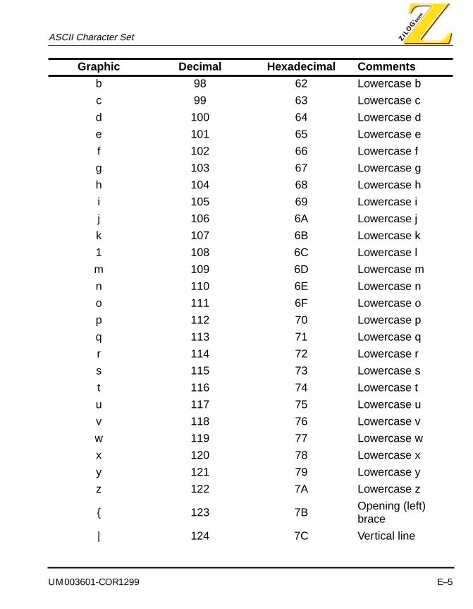
UM003601-COR1299 E–5
ASCII Character Set
b 98 62 Lowercase b
c 99 63 Lowercase c
d 100 64 Lowercase d
e 101 65 Lowercase e
f 102 66 Lowercase f
g 103 67 Lowercase g
h 104 68 Lowercase h
i 105 69 Lowercase i
j 106 6A Lowercase j
k 107 6B Lowercase k
1 108 6C Lowercase l
m 109 6D Lowercase m
n 110 6E Lowercase n
o 111 6F Lowercase o
p 112 70 Lowercase p
q 113 71 Lowercase q
r 114 72 Lowercase r
s 115 73 Lowercase s
t 116 74 Lowercase t
u 117 75 Lowercase u
v 118 76 Lowercase v
w 119 77 Lowercase w
x 120 78 Lowercase x
y 121 79 Lowercase y
z 122 7A Lowercase z
{ 123 7BOpening (left) brace
| 124 7C Vertical line
Graphic Decimal Hexadecimal Comments

ASCII Character Set
E–6 UM003601-COR1299
} 125 7DClosing (right) brace
~ 126 7E Tilde
127 7F Delete
Graphic Decimal Hexadecimal Comments

UM003601-COR1299 F–1
ZILOG MACRO CROSS ASSEMBLER
APPENDIX F
SAMPLE OF OUTPUT FILE PRINTOUTS
OUTPUT FILES
Various output files are created when source files are assembled and linked. The following pages display sample output pages containing data types: .MAP, .ASM, .HEX, .IHX, .SYM, .1ST, and .PMF.
.MAP FILE
Zilog Linkage Editor. Version I2.11 12-Mar-99 13:32:15 Page: 1
LINK MAP:
Date: Fri Mar 12 13:32:15 1999Processor: Z8Files: [Object ] reaction.o
COMMAND LIST:============= 1: -a -g -mreaction.map -oreaction.hex reaction.o
Zilog Linkage Editor. Version I2.11 12-Mar-99 13:32:15 Page: 2
SPACE ALLOCATION:=================
Space Base Top Span -------------------------------- -------- -------- --------ROM 00000000 00000177 178h

.MAP file Sample of Output File Printouts
F–2 UM003601-COR1299
SEGMENTS WITHIN SPACE:======================
ROM Type Base Top Span -------------------------------- ----------- -------- -------- -------- code absolute 00000000 00000177 178h
Zilog Linkage Editor. Version I2.11 12-Mar-99 13:32:15 Page: 3
SEGMENTS WITHIN MODULES:========================
Module: reaction.s (File: reaction.o) Fri Mar 12 13:32:15 1999
Name Base Top Size -------------------------------- -------- -------- -------- Segment: code 00000000 00000177 376
Zilog Linkage Editor. Version I2.11 12-Mar-99 13:32:15 Page: 4
EXTERNAL DEFINITIONS BY ADDRESS:================================
Symbol Address Module Segment -------------------------------- -------- ------------ --------------------------------Main 00000000 reaction.s codeStart 00000026 reaction.s codezero 00000033 reaction.s codemain_loop 0000004F reaction.s codeBlink 0000005D reaction.s codeblnkret 00000063 reaction.s codeStart_Int 00000064 reaction.s codeIntret 00000074 reaction.s codeInterval 00000075 reaction.s codeTimeOut 00000077 reaction.s codeReact 0000008B reaction.s codeokay 00000093 reaction.s codePush 00000094 reaction.s codeDebounce 000000A3 reaction.s code

UM003601-COR1299 F–3
Sample of Output File Printouts .MAP file
debo 000000A5 reaction.s codevalid 000000B2 reaction.s codecnt_ones 000000B4 reaction.s codeCount 000000B4 reaction.s codecnt_tens 000000BF reaction.s codecnt_huns 000000CA reaction.s codecomp_ones 000000D2 reaction.s codecomp_tens 000000D9 reaction.s codecomp_huns 000000E0 reaction.s codeload_best 000000E5 reaction.s codeDisplay 000000EB reaction.s coderepeat 000000F0 reaction.s codedisp_hun 00000118 reaction.s codeonlose 0000011F reaction.s codeon 00000127 reaction.s codepoint 0000012B reaction.s codeon_loop 00000134 reaction.s codeLoser 00000139 reaction.s codelose_rep 0000013B reaction.s codelose 0000013D reaction.s codeBest 0000014F reaction.s codePSHBTN 0000015A reaction.s codeIRQ3 0000015D reaction.s codeIRQ1 0000015D reaction.s codeTMR1 0000015D reaction.s codeIRQ4 0000015D reaction.s codeIRQ2 0000015D reaction.s codenumber 0000015F reaction.s codeloser_tab 00000171 reaction.s codeT1_BLINK 00000000 reaction.s (unknown)PRE1_BLINK 00000003 reaction.s (unknown)best_ones 00000004 reaction.s (unknown)best_tens 00000005 reaction.s (unknown)best_huns 00000006 reaction.s (unknown)R1_INIT 0000000F reaction.s (unknown)Reg1 00000020 reaction.s (unknown)low 000000AA reaction.s (unknown)T1_REACT 000000C8 reaction.s (unknown)PRE1_REACT 000000CB reaction.s (unknown)User_flag 000000FC reaction.s (unknown)
Zilog Linkage Editor. Version I2.11 12-Mar-99 13:32:15 Page: 5

.MAP file Sample of Output File Printouts
F–4 UM003601-COR1299
Symbol Address Module Segment -------------------------------- -------- ------------ -------------------------------- 54 External symbols.
Zilog Linkage Editor. Version I2.11 12-Mar-99 13:32:15 Page: 6
EXTERNAL DEFINITIONS BY NAME:=============================
Symbol Address Module Segment -------------------------------- -------- ------------ --------------------------------Best 0000014F reaction.s codebest_huns 00000006 reaction.s (unknown)best_ones 00000004 reaction.s (unknown)best_tens 00000005 reaction.s (unknown)Blink 0000005D reaction.s codeblnkret 00000063 reaction.s codecnt_huns 000000CA reaction.s codecnt_ones 000000B4 reaction.s codecnt_tens 000000BF reaction.s codecomp_huns 000000E0 reaction.s codecomp_ones 000000D2 reaction.s codecomp_tens 000000D9 reaction.s codeCount 000000B4 reaction.s codedebo 000000A5 reaction.s codeDebounce 000000A3 reaction.s codedisp_hun 00000118 reaction.s codeDisplay 000000EB reaction.s codeInterval 00000075 reaction.s codeIntret 00000074 reaction.s codeIRQ1 0000015D reaction.s codeIRQ2 0000015D reaction.s codeIRQ3 0000015D reaction.s codeIRQ4 0000015D reaction.s codeload_best 000000E5 reaction.s codelose 0000013D reaction.s codelose_rep 0000013B reaction.s codeLoser 00000139 reaction.s codeloser_tab 00000171 reaction.s codelow 000000AA reaction.s (unknown)Main 00000000 reaction.s code
UM003601-COR1299 F–5
Sample of Output File Printouts .MAP file
main_loop 0000004F reaction.s codenumber 0000015F reaction.s codeokay 00000093 reaction.s codeon 00000127 reaction.s codeon_loop 00000134 reaction.s codeonlose 0000011F reaction.s codepoint 0000012B reaction.s codePRE1_BLINK 00000003 reaction.s (unknown)PRE1_REACT 000000CB reaction.s (unknown)PSHBTN 0000015A reaction.s codePush 00000094 reaction.s codeR1_INIT 0000000F reaction.s (unknown)React 0000008B reaction.s codeReg1 00000020 reaction.s (unknown)repeat 000000F0 reaction.s codeStart 00000026 reaction.s codeStart_Int 00000064 reaction.s codeT1_BLINK 00000000 reaction.s (unknown)T1_REACT 000000C8 reaction.s (unknown)TimeOut 00000077 reaction.s codeTMR1 0000015D reaction.s codeUser_flag 000000FC reaction.s (unknown)valid 000000B2 reaction.s codezero 00000033 reaction.s code
Zilog Linkage Editor. Version I2.11 12-Mar-99 13:32:15 Page: 7
Symbol Address Module Segment -------------------------------- -------- ------------ -------------------------------- 54 External symbols.
Zilog Linkage Editor. Version I2.11 12-Mar-99 13:32:15 Page: 8
SYMBOL CROSS REFERENCE:=======================
Symbol Module Use -------------------------------- ------------ ---------- Best reaction.s Definitionbest_huns reaction.s Definition
.MAP file Sample of Output File Printouts
F–6 UM003601-COR1299
best_ones reaction.s Definitionbest_tens reaction.s DefinitionBlink reaction.s Definitionblnkret reaction.s Definitioncnt_huns reaction.s Definitioncnt_ones reaction.s Definitioncnt_tens reaction.s Definitioncomp_huns reaction.s Definitioncomp_ones reaction.s Definitioncomp_tens reaction.s DefinitionCount reaction.s Definitiondebo reaction.s DefinitionDebounce reaction.s Definitiondisp_hun reaction.s DefinitionDisplay reaction.s DefinitionInterval reaction.s DefinitionIntret reaction.s DefinitionIRQ1 reaction.s DefinitionIRQ2 reaction.s DefinitionIRQ3 reaction.s DefinitionIRQ4 reaction.s Definitionload_best reaction.s Definitionlose reaction.s Definitionlose_rep reaction.s DefinitionLoser reaction.s Definitionloser_tab reaction.s Definitionlow reaction.s DefinitionMain reaction.s Definitionmain_loop reaction.s Definitionnumber reaction.s Definitionokay reaction.s Definitionon reaction.s Definitionon_loop reaction.s Definitiononlose reaction.s Definitionpoint reaction.s DefinitionPRE1_BLINK reaction.s DefinitionPRE1_REACT reaction.s DefinitionPSHBTN reaction.s DefinitionPush reaction.s DefinitionR1_INIT reaction.s DefinitionReact reaction.s DefinitionReg1 reaction.s Definitionrepeat reaction.s DefinitionStart reaction.s Definition

UM003601-COR1299 F–7
Sample of Output File Printouts .MAP file
Start_Int reaction.s DefinitionT1_BLINK reaction.s DefinitionT1_REACT reaction.s DefinitionTimeOut reaction.s DefinitionTMR1 reaction.s DefinitionUser_flag reaction.s Definitionvalid reaction.s Definitionzero reaction.s Definition
Zilog Linkage Editor. Version I2.11 12-Mar-99 13:32:15 Page: 9
Symbol Module Use -------------------------------- ------------ ---------- End of link map:================ 0 Warnings 0 Errors

.HEX file Sample of Output File Printouts
F–8 UM003601-COR1299
.HEX FILE
:10000000015A015D015D015D015D015DE6F600E6FD:10001000F701E6F804E6F91CE6FB21E6040FE60525:100020000FE6060F3110B0FCE6FF40B0FA9FE62065:1000300010FC0FB1202020FAFAE602FFE6F200E6FB:10004000F303E6F10C1C0F9C5D8C007C646C007665:10005000FC016BFBA6E0006D01398D00B41A046051:10006000001C0FBFE6000118F246E12F9C758C00C2:100070007C946C00BF1AFDE6F100E6F2C8E6F3CB13:10008000E60000E6F10C9C8B8C00BF0EA6E000EBB6:10009000028B01BFE6F1007C266C0050FC46FC019F:1000A00070FCBFAC0380EAEBFC54FEFA7603046BF1:1000B00001BF30E6A6E0645B062E26E0648BF5A661:1000C000E00A5B0626E00A3E8BF526E0015B034E64:1000D0008BF8A4E2045B14EB0CA4E3055B0DEB05C9:1000E000A4E4065B06290439054906E600011C055F:1000F000E602FFD6013458E2D60127E602F7D60120:100100003458E3D60127E602FFCC2FD601341A0873:100110007C4F6C01FF7F8BD358E4D601278BD160D5:1001200000FC71EC018B04FC5FEC0102F516EE00A3:10013000C20E090280ECEBFCAF1C055C06D6011F69:100140005AFB1AF77C4F6C01E60001FF7F8B9C285D:1001500004380548067C266C00BF8D00A330E80AF1:10016000FA2CA8D88909BA089818490F680D1DF704:08017000FFFFFF1F0D890A4F7C:00000003FD:00000001FF

UM003601-COR1299 F–9
Sample of Output File Printouts .LST file
.LST FILE
Zilog Macro Assembler. Version J2.11 12-Mar-99 13:32:15 Page: 1
reaction.s
Location Object Type Line Source A 1 ;***************************** A 2 ;* REACT_02.ASM (7-23-96) * A 3 ;***************************** A 4 A 5 ;******************************************************* A 6 ;* This is a reaction timer test program written by * A 7 ;* Chris Miller for the Z8 "Fast Design" Seminar, 7/96.* A 8 ;******************************************************* A 9 A 10 A 11 ;*************************************************************** A 12 ;* Counter Timer 1 is set up to count down to zero every * A 13 ;* 10ms with an 8 MHz XTAL. The formula is: * A 14 ;* * A 15 ;* i = t x p x v * A 16 ;* * A 17 ;* i = desired time interval until end of T/C count * A 18 ;* t = input clock period (8 divided by the XTAL frequency) * A 19 ;* p = prescaler value (1-64 decimal) * A 20 ;* v = T/C value (1-256 decimal) *

.LST file Sample of Output File Printouts
F–10 UM003601-COR1299
A 21 ;* * A 22 ;* Therefore, 10ms = 1us x 50 x 200 * A 23 ;* * A 24 ;*************************************************************** A 25 GLOBALS ON A 26 00000000 A 27 Main: A 28 00000003 A 29 PRE1_BLINK .equ %03 ; T1 modulo n, count = 64 00000000 A 30 T1_BLINK .equ %00 ; T1 max. count = 256 decimal 000000CB A 31 PRE1_REACT .equ %cb ; T1 modulo n, count = 50 decimal 000000C8 A 32 T1_REACT .equ %c8 ; T1 count = 200 decimal 0000000F A 33 R1_INIT .equ %0f ; Extra blink interval R0 A 34 react_time .equ r0 ; Reaction time counter register R2 A 35 ones .equ r2 ; Ones unit count R3 A 36 tens .equ r3 ; Tenths unit count R4 A 37 huns .equ r4 ; Hundredths unit count R5 A 38 pointer .equ r5 ; Pointer in LED segment tables 00000004 A 39 best_ones .equ %04 ; Best ones unit count 00000005 A 40 best_tens .equ %05 ; Best tenths unit count 00000006 A 41 best_huns .equ %06 ; Best hundredths unit count 00000020 A 42 Reg1 .equ %20 ; Buffer register 1 address 000000FC A 43 User_flag .equ %fc ; Set User_flag as synonym for Flags reg. A 44 ; (Used as decision to exit main_loop)

UM003601-COR1299 F–11
Sample of Output File Printouts .LST file
A 45 A 46 A 47 ;********************************* A 48 ;** Timer State-Machine Macro ** A 49 ;********************************* 000000AA A 50 low equ low %55aa A 51 TIMER .macro jump A 52 A 53 ld r9, #low jump ; Load starting address of jump A 54 ld r8, #high jump A 55 A 56 .endm A 57 A 58
Zilog Macro Assembler. Version J2.11 12-Mar-99 13:32:15 Page: 2
reaction.s
Location Object Type Line Source A 59 ;********************************** A 60 ;** Button State-Machine Macro ** A 61 ;********************************** A 62 A 63 BUTTON .macro jump A 64 A 65 ld r7, #low jump ; Load starting address of jump A 66 ld r6, #high jump A 67 A 68 .endm A 69 A 70 ;======================================================================= A 71

.LST file Sample of Output File Printouts
F–12 UM003601-COR1299
A 72 A 73 ;************************* A 74 ;** Interrupt Vectors ** A 75 ;************************* A 76 A 77 .org %0 ; Setup interrupt vectors A 78 00000000 01 5A A 79 .word PSHBTN ; Interrupt 000000002 01 5D A 80 .word IRQ1 ; " 100000004 01 5D A 81 .word IRQ2 ; " 200000006 01 5D A 82 .word IRQ3 ; " 300000008 01 5D A 83 .word IRQ4 ; " 40000000A 01 5D A 84 .word TMR1 ; " 5 A 85 A 86 A 87 A 88 ;************************ A 89 ;** Initialize ** A 90 ;************************ A 91 A 92 .org %0c ; Start of program A 93 0000000C E6 F6 00 A 94 ld P2M, #%0 ; Init Port 2 mode as outputs 0000000F E6 F7 01 A 95 ld P3M, #%01 ; Init Port 3=digital in, Port 2=push pull00000012 E6 F8 04 A 96 ld P01M, #%04 ; Init Port 1 mode as outputs00000015 E6 F9 1C A 97 ld IPR, #%1c ; Int. Priority: IRQ0>IRQ5 00000018 E6 FB 21 A 98 ld IMR, #%21 ; Enables IRQ0 & IRQ5 but not Global enable0000001B E6 04 0F A 99 ld best_ones, #%0f ; Load Best ones unit with F hex0000001E E6 05 0F A 100 ld best_tens, #%0f ; Load Best tenths unit with F hex

UM003601-COR1299 F–13
Sample of Output File Printouts .LST file
00000021 E6 06 0F A 101 ld best_huns, #%0f ; Load Best hundredths unit with F hex00000024 31 10 A 102 srp #%10 ; Set reg. pointer to Working Reg. 1, Bank 0 A 103 A 104 A 105 ;************* A 106 ;** START ** A 107 ;************* A 108 00000026 A 109 Start:00000026 B0 FC A 110 clr User_flag ; Clear User flag (Flags) register00000028 E6 FF 40 A 111 ld SPL, #%40 ; Init Stack Pointer0000002B B0 FA A 112 clr IRQ ; Reset IRQ0000002D 9F A 113 ei ; Globally enable interrupts & IRQ A 114 A 115 ;* Clear Registers * A 116
Zilog Macro Assembler. Version J2.11 12-Mar-99 13:32:15 Page: 3
reaction.s
Location Object Type Line Source0000002E E6 20 10 A 117 ld Reg1, #%10 ; Address of r0 (according to Reg. Pointer)00000031 FC 0F A 118 ld r15, #15 ; 15 locations A 119 ; (decrementing r15 will clear it)00000033 B1 20 A 120 zero: clr @Reg1 ; Clear all reg. in Working Reg. 1, Bank 000000035 20 20 A 121 inc Reg100000037 FA FA A 122 djnz r15, zero ; Cleared all registers yet? A 123 00000039 E6 02 FF A 124 ld P2, #%ff ; Turn off number segment

.LST file Sample of Output File Printouts
F–14 UM003601-COR1299
A 125 0000003C E6 F2 00 A 126 ld T1,#T1_BLINK ; Initialize T1 value for blinking 0000003F E6 F3 03 A 127 ld PRE1, #PRE1_BLINK ; Initialize PRE1 value and modulo n 00000042 E6 F1 0C A 128 ld TMR, #%0c ; Load T1 & start counting00000045 1C 0F A 129 ld r1,#R1_INIT ; Extra interval A 130 A 131 TIMER Blink ; Load TIMER macro with "Blink" addr. A+ 131 00000047 9C 5D A+ 131 ld r9, #low jump ; Load starting address of jump00000049 8C 00 A+ 131 ld r8, #high jump A+ 131 A 132 BUTTON Start_Int ; Load BUTTON macro with "Start_Int" addr. A+ 132 0000004B 7C 64 A+ 132 ld r7, #low jump ; Load starting address of jump0000004D 6C 00 A+ 132 ld r6, #high jump A+ 132 A 133 A 134 0000004F A 135 main_loop:0000004F 76 FC 01 A 136 tm User_flag, #%01 ; Is User flag bit #1 set? 00000052 6B FB A 137 jr z, main_loop ; No, then loop & wait for interrupt A 138 00000054 A6 E0 00 A 139 cp react_time, #%00 ; Yes, then is there a valid count value? 00000057 6D 01 39 A 140 jp eq, Loser ; No, then goto Loser0000005A 8D 00 B4 A 141 jp Count ; Yes, then goto Count A 142 A 143 A 144 A 145 ;******************* A 146 ;* Blink Led * A 147 ;*******************
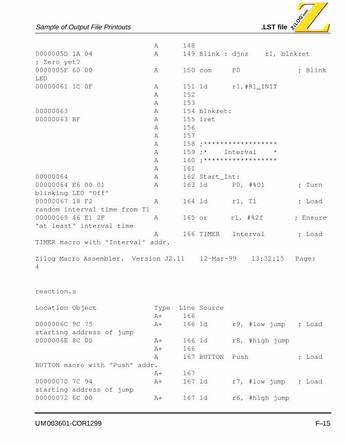
UM003601-COR1299 F–15
Sample of Output File Printouts .LST file
A 148 0000005D 1A 04 A 149 Blink : djnz r1, blnkret ; Zero yet?0000005F 60 00 A 150 com P0 ; Blink LED00000061 1C 0F A 151 ld r1,#R1_INIT A 152 A 153 00000063 A 154 blnkret:00000063 BF A 155 iret A 156 A 157 A 158 ;****************** A 159 ;* Interval * A 160 ;****************** A 161 00000064 A 162 Start_Int: 00000064 E6 00 01 A 163 ld P0, #%01 ; Turn blinking LED "Off"00000067 18 F2 A 164 ld r1, T1 ; Load random interval time from T1 00000069 46 E1 2F A 165 or r1, #%2f ; Ensure "at least" interval time A 166 TIMER Interval ; Load TIMER macro with "Interval" addr.
Zilog Macro Assembler. Version J2.11 12-Mar-99 13:32:15 Page: 4
reaction.s
Location Object Type Line Source A+ 166 0000006C 9C 75 A+ 166 ld r9, #low jump ; Load starting address of jump0000006E 8C 00 A+ 166 ld r8, #high jump A+ 166 A 167 BUTTON Push ; Load BUTTON macro with "Push" addr. A+ 167 00000070 7C 94 A+ 167 ld r7, #low jump ; Load starting address of jump00000072 6C 00 A+ 167 ld r6, #high jump

.LST file Sample of Output File Printouts
F–16 UM003601-COR1299
A+ 167 A 168 00000074 BF A 169 Intret: iret A 170 00000075 A 171 Interval:00000075 1A FD A 172 djnz r1, Intret ; Interval timeout? Yes, proceed to TimeOut A 173 A 174 A 175 ;***************** A 176 ;* TimeOut * A 177 ;***************** A 178 00000077 A 179 TimeOut: 00000077 E6 F1 00 A 180 ld TMR, #%00 ; Disable T1 to load new value0000007A E6 F2 C8 A 181 ld T1,#T1_REACT ; Beginning value of T1 for reaction0000007D E6 F3 CB A 182 ld PRE1,#PRE1_REACT ; Modulo n, external00000080 E6 00 00 A 183 ld P0, #%00 ; Turn on LED00000083 E6 F1 0C A 184 ld TMR, #%0c ; Load T1 & start counting A 185 TIMER React ; Load TIMER macro with "React" addr. A+ 185 00000086 9C 8B A+ 185 ld r9, #low jump ; Load starting address of jump00000088 8C 00 A+ 185 ld r8, #high jump A+ 185 0000008A BF A 186 iret A 187 A 188 A 189 ;*********************** A 190 ;* Reaction Time * A 191 ;*********************** A 192 0000008B 0E A 193 React: inc react_time0000008C A6 E0 00 A 194 cp react_time, #%00 ; Count equal to 256?0000008F EB 02 A 195 jr ne, okay ; Too long for reaction (2.56 sec)?
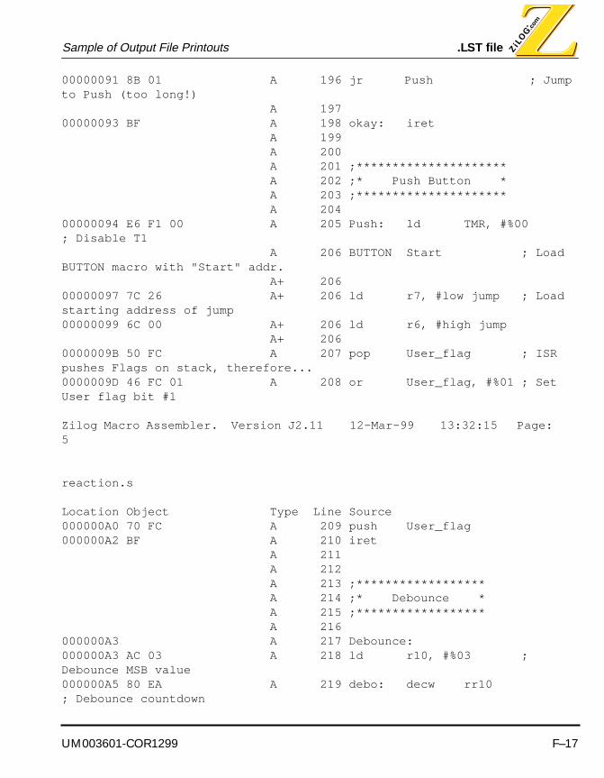
UM003601-COR1299 F–17
Sample of Output File Printouts .LST file
00000091 8B 01 A 196 jr Push ; Jump to Push (too long!) A 197 00000093 BF A 198 okay: iret A 199 A 200 A 201 ;********************* A 202 ;* Push Button * A 203 ;********************* A 204 00000094 E6 F1 00 A 205 Push: ld TMR, #%00 ; Disable T1 A 206 BUTTON Start ; Load BUTTON macro with "Start" addr. A+ 206 00000097 7C 26 A+ 206 ld r7, #low jump ; Load starting address of jump00000099 6C 00 A+ 206 ld r6, #high jump A+ 206 0000009B 50 FC A 207 pop User_flag ; ISR pushes Flags on stack, therefore...0000009D 46 FC 01 A 208 or User_flag, #%01 ; Set User flag bit #1
Zilog Macro Assembler. Version J2.11 12-Mar-99 13:32:15 Page: 5
reaction.s
Location Object Type Line Source000000A0 70 FC A 209 push User_flag000000A2 BF A 210 iret A 211 A 212 A 213 ;****************** A 214 ;* Debounce * A 215 ;****************** A 216 000000A3 A 217 Debounce:000000A3 AC 03 A 218 ld r10, #%03 ; Debounce MSB value000000A5 80 EA A 219 debo: decw rr10 ; Debounce countdown

.LST file Sample of Output File Printouts
F–18 UM003601-COR1299
000000A7 EB FC A 220 jr nz, debo000000A9 54 FE FA A 221 and irq, %fe ; Clear INT0 (push button) in IRQ000000AC 76 03 04 A 222 tm P3, #%04 ; Sample port pin 32 again000000AF 6B 01 A 223 jr z, valid ; Test for valid button or not000000B1 BF A 224 iret ; No, then return to main_loop000000B2 30 E6 A 225 valid: jp @rr6 ; Yes, then jump to correct state A 226 A 227 A 228 ;********************************** A 229 ;** Count Value for 8 MHz XTAL ** A 230 ;********************************** A 231 000000B4 A 232 Count: A 233 000000B4 A 234 cnt_ones:000000B4 A6 E0 64 A 235 cp react_time, #%64 ; Greater or less than 100 decimal000000B7 5B 06 A 236 jr mi, cnt_tens ; Less than or equal, then tenths000000B9 2E A 237 inc ones000000BA 26 E0 64 A 238 sub react_time, #%64 ; Interested only in whole part000000BD 8B F5 A 239 jr cnt_ones A 240 000000BF A 241 cnt_tens:000000BF A6 E0 0A A 242 cp react_time, #%0a ; Greater or less than 10 decimal = 1/10 000000C2 5B 06 A 243 jr mi, cnt_huns ; Less than or equal, then hundredths000000C4 26 E0 0A A 244 sub react_time, #%0a ; Subtract 10 decimal = 1/10000000C7 3E A 245 inc tens ; Add another tenth000000C8 8B F5 A 246 jr cnt_tens A 247 000000CA A 248 cnt_huns:

UM003601-COR1299 F–19
Sample of Output File Printouts .LST file
000000CA 26 E0 01 A 249 sub react_time, #%01 ; Subtract 1 decimal = 1/100000000CD 5B 03 A 250 jr mi, comp_ones ; Less than or equal, then compare "Best"000000CF 4E A 251 inc huns ; Add another hundredth000000D0 8B F8 A 252 jr cnt_huns A 253 A 254 A 255 ;***************************** A 256 ;** Best Time Calculation ** A 257 ;***************************** A 258 000000D2 A 259 comp_ones:000000D2 A4 E2 04 A 260 cp best_ones, ones ; Is it best ones value? 000000D5 5B 14 A 261 jr mi, Display ; No, then keep old "Best", goto Display000000D7 EB 0C A 262 jr nz, load_best A 263 000000D9 A 264 comp_tens:000000D9 A4 E3 05 A 265 cp best_tens, tens ; Is it best tens value?000000DC 5B 0D A 266 jr mi, Display ; No, then keep old "Best", goto Display
Zilog Macro Assembler. Version J2.11 12-Mar-99 13:32:15 Page: 6
reaction.s
Location Object Type Line Source000000DE EB 05 A 267 jr nz, load_best A 268 000000E0 A 269 comp_huns:000000E0 A4 E4 06 A 270 cp best_huns, huns ; Is it best huns value?000000E3 5B 06 A 271 jr mi, Display ; No, then keep old "Best", goto Display A 272 000000E5 A 273 load_best:000000E5 29 04 A 274 ld best_ones, ones ; Load new "Best" ones value

.LST file Sample of Output File Printouts
F–20 UM003601-COR1299
000000E7 39 05 A 275 ld best_tens, tens ; Load new "Best" tenths value000000E9 49 06 A 276 ld best_huns, huns ; Load new "Best" hundredths value A 277 A 278 A 279 ;********************* A 280 ;** Display ** A 281 ;********************* A 282 A 283 000000EB A 284 Display:000000EB E6 00 01 A 285 ld P0,#%01 ; Turn off LED000000EE 1C 05 A 286 ld r1, #5 ; Load "repeat" counter A 287 000000F0 A 288 repeat: A 289 A 290 ;* Off * A 291 000000F0 E6 02 FF A 292 ld P2, #%ff ; Load "Off" value000000F3 D6 01 34 A 293 call on_loop A 294 A 295 ;* Ones * A 296 000000F6 58 E2 A 297 ld pointer, ones ; Load ones value000000F8 D6 01 27 A 298 call on A 299 A 300 ;* Decimal * A 301 000000FB E6 02 F7 A 302 ld P2, #%f7 ; Load "." value000000FE D6 01 34 A 303 call on_loop A 304 A 305 ;* Tenths * A 306 00000101 58 E3 A 307 ld pointer, tens ; Load tenths value00000103 D6 01 27 A 308 call on A 309 A 310 ;* Off *
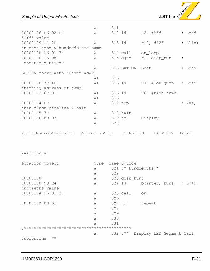
UM003601-COR1299 F–21
Sample of Output File Printouts .LST file
A 311 00000106 E6 02 FF A 312 ld P2, #%ff ; Load "Off" value00000109 CC 2F A 313 ld r12, #%2f ; Blink in case tens & hundreds are same 0000010B D6 01 34 A 314 call on_loop0000010E 1A 08 A 315 djnz r1, disp_hun ; Repeated 5 times? A 316 BUTTON Best ; Load BUTTON macro with "Best" addr. A+ 316 00000110 7C 4F A+ 316 ld r7, #low jump ; Load starting address of jump00000112 6C 01 A+ 316 ld r6, #high jump A+ 316 00000114 FF A 317 nop ; Yes, then flush pipeline & halt00000115 7F A 318 halt00000116 8B D3 A 319 jr Display A 320
Zilog Macro Assembler. Version J2.11 12-Mar-99 13:32:15 Page: 7
reaction.s
Location Object Type Line Source A 321 ;* Hundredths * A 322 00000118 A 323 disp_hun:00000118 58 E4 A 324 ld pointer, huns ; Load hundreths value0000011A D6 01 27 A 325 call on A 326 0000011D 8B D1 A 327 jr repeat A 328 A 329 A 330 A 331 ;******************************************* A 332 ;** Display LED Segment Call Subroutine **
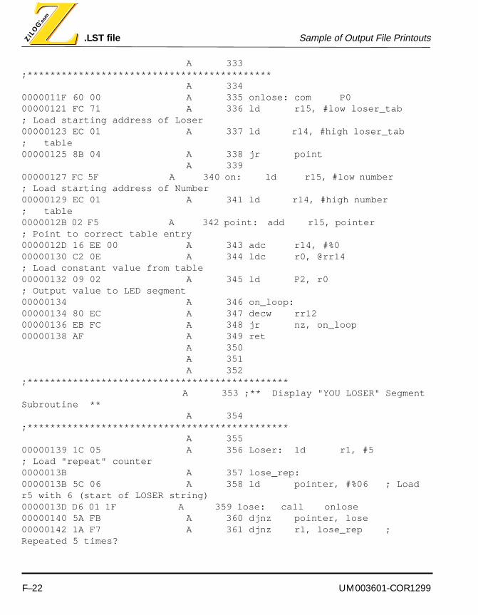
.LST file Sample of Output File Printouts
F–22 UM003601-COR1299
A 333 ;******************************************* A 334 0000011F 60 00 A 335 onlose: com P000000121 FC 71 A 336 ld r15, #low loser_tab ; Load starting address of Loser00000123 EC 01 A 337 ld r14, #high loser_tab ; table 00000125 8B 04 A 338 jr point A 339 00000127 FC 5F A 340 on: ld r15, #low number ; Load starting address of Number00000129 EC 01 A 341 ld r14, #high number ; table0000012B 02 F5 A 342 point: add r15, pointer ; Point to correct table entry0000012D 16 EE 00 A 343 adc r14, #%000000130 C2 0E A 344 ldc r0, @rr14 ; Load constant value from table00000132 09 02 A 345 ld P2, r0 ; Output value to LED segment 00000134 A 346 on_loop: 00000134 80 EC A 347 decw rr1200000136 EB FC A 348 jr nz, on_loop00000138 AF A 349 ret A 350 A 351 A 352 ;********************************************** A 353 ;** Display "YOU LOSER" Segment Subroutine ** A 354 ;********************************************** A 355 00000139 1C 05 A 356 Loser: ld r1, #5 ; Load "repeat" counter0000013B A 357 lose_rep:0000013B 5C 06 A 358 ld pointer, #%06 ; Load r5 with 6 (start of LOSER string)0000013D D6 01 1F A 359 lose: call onlose 00000140 5A FB A 360 djnz pointer, lose00000142 1A F7 A 361 djnz r1, lose_rep ; Repeated 5 times?

UM003601-COR1299 F–23
Sample of Output File Printouts .LST file
A 362 BUTTON Best ; Load BUTTON macro with "Best" addr. A+ 362 00000144 7C 4F A+ 362 ld r7, #low jump ; Load starting address of jump00000146 6C 01 A+ 362 ld r6, #high jump A+ 362 00000148 E6 00 01 A 363 ld P0, #%01 ; Turn off LED0000014B FF A 364 nop ; Yes, then flush pipeline & halt0000014C 7F A 365 halt0000014D 8B 9C A 366 jr Display A 367 A 368 ;********************************************** A 369 ;** Display "Best Time" Segment Subroutine ** A 370 ;********************************************** A 371 0000014F 28 04 A 372 Best: ld ones, best_ones00000151 38 05 A 373 ld tens, best_tens00000153 48 06 A 374 ld huns, best_huns
Zilog Macro Assembler. Version J2.11 12-Mar-99 13:32:15 Page: 8
reaction.s
Location Object Type Line Source A 375 BUTTON Start ; Load BUTTON macro with "Start" addr. A+ 375 00000155 7C 26 A+ 375 ld r7, #low jump ; Load starting address of jump00000157 6C 00 A+ 375 ld r6, #high jump A+ 375 00000159 BF A 376 iret A 377 A 378 A 379 ;================================================================

.LST file Sample of Output File Printouts
F–24 UM003601-COR1299
A 380 A 381 ;**************************************** A 382 ;** Interrupt Service Routines ** A 383 ;**************************************** A 384 A 385 0000015A 8D 00 A3 A 386 PSHBTN: jp Debounce ; If pushbutton int. jump to Debounce A 387 0000015D A 388 IRQ1:0000015D A 389 IRQ2:0000015D A 390 IRQ3:0000015D A 391 IRQ4: A 392 0000015D 30 E8 A 393 TMR1: jp @rr8 ; If timer int. jump to address in rr8 A 394 A 395 A 396 ;=========================================== A 397 A 398 A 399 ;**************************** A 400 ;** LED Segment Tables ** A 401 ;**************************** A 402 A 403 0000015F 0A A 404 number: .byte %0a ; number "0"00000160 FA A 405 .byte %fa ; number "1"00000161 2C A 406 .byte %2c ; number "2"00000162 A8 A 407 .byte %a8 ; number "3"00000163 D8 A 408 .byte %d8 ; number "4"00000164 89 A 409 .byte %89 ; number "5"00000165 09 A 410 .byte %09 ; number "6"

UM003601-COR1299 F–25
Sample of Output File Printouts .LST file
00000166 BA A 411 .byte %ba ; number "7"00000167 08 A 412 .byte %08 ; number "8"00000168 98 A 413 .byte %98 ; number "9"00000169 18 A 414 .byte %18 ; letter "A"0000016A 49 A 415 .byte %49 ; letter "B"0000016B 0F A 416 .byte %0f ; letter "C"0000016C 68 A 417 .byte %68 ; letter "D"0000016D 0D A 418 .byte %0d ; letter "E"0000016E 1D A 419 .byte %1d ; letter "F"0000016F F7 A 420 .byte %f7 ; decimal "."00000170 FF A 421 .byte %ff ; Off A 422 A 423 00000171 FF A 424 loser_tab: .byte %ff ; Off00000172 FF A 425 .byte %ff ; Off 00000173 1F A 426 .byte %1f ; letter "r"00000174 0D A 427 .byte %0d ; letter "E"00000175 89 A 428 .byte %89 ; letter "S"
Zilog Macro Assembler. Version J2.11 12-Mar-99 13:32:15 Page: 9
reaction.s
Location Object Type Line Source00000176 0A A 429 .byte %0a ; letter "O"00000177 4F A 430 .byte %4f ; letter "L"
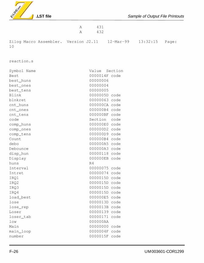
.LST file Sample of Output File Printouts
F–26 UM003601-COR1299
A 431 A 432
Zilog Macro Assembler. Version J2.11 12-Mar-99 13:32:15 Page: 10
reaction.s
Symbol Name Value SectionBest 0000014F codebest_huns 00000006 best_ones 00000004 best_tens 00000005 Blink 0000005D codeblnkret 00000063 codecnt_huns 000000CA codecnt_ones 000000B4 codecnt_tens 000000BF codecode Section codecomp_huns 000000E0 codecomp_ones 000000D2 codecomp_tens 000000D9 codeCount 000000B4 codedebo 000000A5 codeDebounce 000000A3 codedisp_hun 00000118 codeDisplay 000000EB codehuns R4 Interval 00000075 codeIntret 00000074 codeIRQ1 0000015D codeIRQ2 0000015D codeIRQ3 0000015D codeIRQ4 0000015D codeload_best 000000E5 codelose 0000013D codelose_rep 0000013B codeLoser 00000139 codeloser_tab 00000171 codelow 000000AA Main 00000000 codemain_loop 0000004F codenumber 0000015F code

UM003601-COR1299 F–27
Sample of Output File Printouts .LST file
okay 00000093 codeon 00000127 codeon_loop 00000134 codeones R2 onlose 0000011F codepoint 0000012B codepointer R5 PRE1_BLINK 00000003 PRE1_REACT 000000CB PSHBTN 0000015A codePush 00000094 codeR1_INIT 0000000F React 0000008B codereact_time R0 Reg1 00000020 repeat 000000F0 codeStart 00000026 codeStart_Int 00000064 codeT1_BLINK 00000000 T1_REACT 000000C8 tens R3 TimeOut 00000077 codeTMR1 0000015D codeUser_flag 000000FC
Zilog Macro Assembler. Version J2.11 12-Mar-99 13:32:15 Page: 11
reaction.s
Symbol Name Value Sectionvalid 000000B2 codezero 00000033 code
60 Symbols.
Zilog Macro Assembler. Version J2.11 12-Mar-99 13:32:15 Page: 12
reaction.s
Symbol Name References
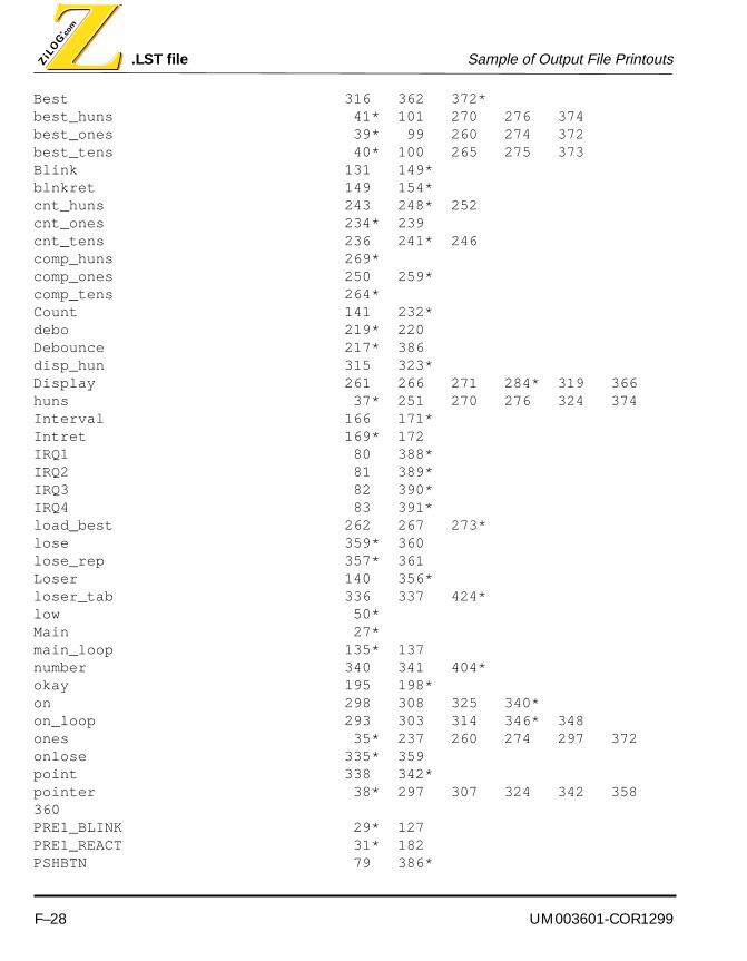
.LST file Sample of Output File Printouts
F–28 UM003601-COR1299
Best 316 362 372*best_huns 41* 101 270 276 374 best_ones 39* 99 260 274 372 best_tens 40* 100 265 275 373 Blink 131 149*blnkret 149 154*cnt_huns 243 248* 252 cnt_ones 234* 239 cnt_tens 236 241* 246 comp_huns 269*comp_ones 250 259*comp_tens 264*Count 141 232*debo 219* 220 Debounce 217* 386 disp_hun 315 323*Display 261 266 271 284* 319 366 huns 37* 251 270 276 324 374 Interval 166 171*Intret 169* 172 IRQ1 80 388*IRQ2 81 389*IRQ3 82 390*IRQ4 83 391*load_best 262 267 273*lose 359* 360 lose_rep 357* 361 Loser 140 356*loser_tab 336 337 424*low 50*Main 27*main_loop 135* 137 number 340 341 404*okay 195 198*on 298 308 325 340*on_loop 293 303 314 346* 348 ones 35* 237 260 274 297 372 onlose 335* 359 point 338 342*pointer 38* 297 307 324 342 358 360 PRE1_BLINK 29* 127 PRE1_REACT 31* 182 PSHBTN 79 386*
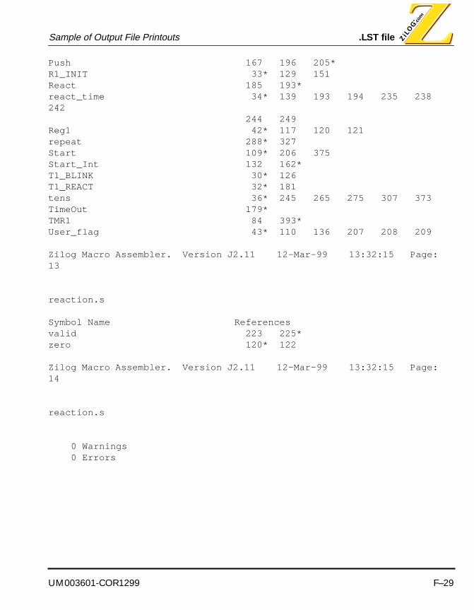
UM003601-COR1299 F–29
Sample of Output File Printouts .LST file
Push 167 196 205*R1_INIT 33* 129 151 React 185 193*react_time 34* 139 193 194 235 238 242 244 249 Reg1 42* 117 120 121 repeat 288* 327 Start 109* 206 375 Start_Int 132 162*T1_BLINK 30* 126 T1_REACT 32* 181 tens 36* 245 265 275 307 373 TimeOut 179*TMR1 84 393*User_flag 43* 110 136 207 208 209
Zilog Macro Assembler. Version J2.11 12-Mar-99 13:32:15 Page: 13
reaction.s
Symbol Name Referencesvalid 223 225*zero 120* 122
Zilog Macro Assembler. Version J2.11 12-Mar-99 13:32:15 Page: 14
reaction.s
0 Warnings 0 Errors

.SYM file Sample of Output File Printouts
F–30 UM003601-COR1299
.SYM FILE
loser_tab X 00000171number X 0000015FIRQ1 X 0000015DIRQ2 X 0000015DIRQ3 X 0000015DIRQ4 X 0000015DTMR1 X 0000015DPSHBTN X 0000015ABest X 0000014Flose X 0000013Dlose_rep X 0000013BLoser X 00000139on_loop X 00000134point X 0000012Bon X 00000127onlose X 0000011Fdisp_hun X 00000118repeat X 000000F0Display X 000000EBload_best X 000000E5comp_huns X 000000E0comp_tens X 000000D9comp_ones X 000000D2cnt_huns X 000000CAcnt_tens X 000000BFCount X 000000B4cnt_ones X 000000B4valid X 000000B2debo X 000000A5Debounce X 000000A3Push X 00000094okay X 00000093React X 0000008BTimeOut X 00000077Interval X 00000075Intret X 00000074Start_Int X 00000064blnkret X 00000063Blink X 0000005Dmain_loop X 0000004Fzero X 00000033Start X 00000026

UM003601-COR1299 F–31
Sample of Output File Printouts .SYM file
Main X 00000000PRE1_BLINK X 00000003T1_BLINK X 00000000PRE1_REACT X 000000CBT1_REACT X 000000C8R1_INIT X 0000000Fbest_ones X 00000004best_tens X 00000005best_huns X 00000006Reg1 X 00000020User_flag X 000000FClow X 000000AA


UM003601-COR1299 Glossary-1
ZILOG MACRO CROSS ASSEMBLER
GLOSSARY
ABS Absolute Value
Address Space Physical or logical area of the target system’sMemory Map. The memory map could be physicallypartitioned into ROM to store code, and RAM for data.The memory can also be divided logically to form sepa-rate areas for code and data storage.
ANSI American National Standards Institute.
ASAP As Soon As Possible.
ASCII American Standard Code of Information Interchange.
ASM Assembler File.
ASYNC Asynchronous Communication Protocol.
ATM Asynchronous Transfer Mode.
B Binary.
Baud Unit of measure of transmission capacity.
Binary Number system based on 2. A binary digit is a bit.
BISYNC Bidirectional Synchronous Communication Protocol.
Bisynchronous Communications A protocol for communications data transfer used
extensive in mainframe computer networks. The

Glossary
Glossary-2 UM003601-COR1299
sending and receiving computers synchronize theirclocks before data transfer may begin.
Bit A digit of a binary system. It has only two possible values: 0 or 1.
BPS Bits Per Second. Number of binary digits transmittedevery second during a data-transfer procedure.
Buffer Storage Area in Memory.
Bug A defect or unexpected characteristic or event.
Bus In Electronics, a parallel interconnection of the internalunits of a system that enables data transfer andcontrol Information.
Byte A collection of four sequential bits of memory. Twosequential bytes (8 bits) comprise one word.
CALL This command invokes a subroutine
Checksum A field of one or more bytes appended to a block of nwords which contains a truncated binary sum formedfrom the contents of that block. The sum is used toverify the integrity of data in a ROM or on a tape.
COM Device name used to designate a communicationport.

UM003601-COR1299 Glossary-3
Glossary
Control Section A continuous logical area containing code or user data. Each control section has a name. The linker putsall those control sections with the same name in oneentity. The linker provides address spaces to thecontrol sections. There are either absolute controlsections or relocatable ones.
CPU Central Processing Unit.
Cross-Linkage Editor A linkage editor that executes on a processor that is notthe same as the target processor.
DI Disable Interrupt.
DIP Dual In-line Package. The plastic housing designed tobe attached directly to a circuit board or equipmentcase.
DSP Digital Signal Processing. A specialized micropro-cessor that is tailored to perform high repetition math processing and improve signal quality.
EPROM Erasable Programmable Read-Only Memory.
EEPROM Electrically Erasable Programmable Read-OnlyMemory.
EI Enable Interrupt.
Emulation Process of duplicating the behavior of one product or part using another medium.
Emulator An emulation device. For example, an In-Circuit Emulator (ICE) module duplicates the behavior of the chip it emulates in the circuit being tested.
External Symbol A symbol that is referenced in the current program filebut is defined in another program file.
GUI Graphical User Interface. The windows and text that a user sees on their computer screen when they are using a program.
H Hexadecimal, Half-Carry Flag.
Glossary
Glossary-4 UM003601-COR1299
Hex Hexadecimal.
Hexadecimal A Base-16 Number System. Hex values are oftensubstituted for harder to read binary numbers.
IC Integrated Circuit.
ICE In-Circuit Emulator. A ZiLOG product which supportsthe application design process.
Icon A small screen image representing a specific element like a document, embedded and linkedobjects, or a collection of programs gatheredtogether in a group.
ID Identifier.
IE Interrupt Enable.
IM Immediate Data Addressing Mode.
IMASK Interrupt Mask Register.
IMR Interrupt Mask Register.
INC Increment.
INCW Increment Word.
Initialize To establish start-up parameters, typically involving clearing all of some part of the device’s memory space.
Instruction Command.
INT Interrupt.
Internal Symbol A symbol that is defined in a program file. This symbolcould be visible to multiple functions within the sameprogram file.
I/O Input/Output. In computers, the part of the system thatdeals with interfacing to external devices for input oroutput, such as keyboards or printers.
UM003601-COR1299 Glossary-5
Glossary
IPR Interrupt Priority Register.
Ir Indirect Working-Register Pair Only.
IR Infrared. A light frequency range just below that ofvisible light.
IRQ Interrupt Request.
ISDN Integrated Services Digital Network.
ISO International Standards Organization.
JP Jump.
JR Jump Range.
Library A File Created by a Librarian. This file contains acollection of object modules that were created by anassembler or directly by a C compiler.
Local Symbol Symbol visible only to a particular function within a program file.
Lock Limits Limits set in a financial program that cannot be surpassed.
LSB Least Significant Bit.
LSI Large Scale Integration. A chip that contains 500 to 5,000 gates or transistors.
M1 Machine Cycle 1.
MCU Microcontroller or Microcomputer Unit.
MI Minus.
MLD Multiply and Load.
MPYA Multiply and ADD.
MPYS Multiply and Subtract.

Glossary
Glossary-6 UM003601-COR1299
MSB Most Significant Bit.
Nibble A Group of 4 Bits.
NMI Non-Maskable Interrupt.
NOP No Operation.
Object Module Programming code created by assembling a file withan assembler or compiling a file with a compiler.These are relocatable object modules and are input tothe linker in order to produce an executable file.
OMF Object Module Format.
OPC Operation Code.
Op Code Operation Code.
OTP One-Time Programmable.
PC Personal computer, program counter.
PCON Port configuration register.
PER Peripheral. A device which supports the import oroutput of information.
POP Retrieve a Value from the Stack.
POR Power-On Reset.
Port The point at which a communications circuit termi-nates at a Network, Serial, or Parallel Interface card.
PRE Prescaler.
PROM Programmable Read-Only Memory.
Protocol Formal set of communications procedures governingthe format and control between two communications devices. A protocol determines the type of error checking to be used, the data compression method, if any, how the sending device will indicate that it has

UM003601-COR1299 Glossary-7
Glossary
finished sending a message, and how the receiving device will indicate that it has received a message.
PRT Programmable Reload Timer or Print.
PTR Pointer.
PTT Post, Telephone, and Telegraph. Agency in many countries that is responsible for providing telecommu-nication approvals.
Public/Global Symbol A programming variable that is available to more thanone program file.
PUSH Store a Value In the Stack.
r Working Register Address.
R Register or Working-Register Address, Rising Edge.
RA Relative Address.
RAM Random-Access Memory. A memory that can be written to or read at random. The device is usually volatile, which means the data is lost without power.
RC Resistance/Capacitance.
RD Read.
RES Reset.
Resolution In a digital image, the total number of pixels in the horizontal and vertical directions.
RFSH Refresh.
ROM Read-Only Memory. Nonvolatile memory that storespermanent programs. ROM usually consists of solid-state chips.
ROMCS ROM Chip Select.
RP Register Pointer.

Glossary
Glossary-8 UM003601-COR1299
RR Read Register or Rotate Right.
RS-232C Electronic Industries Association Standard for Asynchronous Transmissions Between a Computerand a Peripheral Device.
SCF Set C Flag.
Schedule Financial Schedule. Computes the costs and profits for each significant product line item (by PSI) for a given period, usually a fiscal month.
SIO Serial Input/Output.
SL Shift Left or Special Lot.
SLL Shift Left Logical.
SMR Stop Mode Recovery.
SN Serial Number.
SOIC Small Outline IC.
SP Stack Pointer.
SPH Stack Pointer High.
SPI Serial Peripheral Interface.
SPL Stack Pointer Low.
SRAM Static Random Access Memory.
SR Shift Right.
SRA Shift Right Arithmetic.
SRC Source.
SSI Small Scale Integration. Chip that contains 5 to 50 gates or transistors.

UM003601-COR1299 Glossary-9
Glossary
Static Characteristic of Random Access Memory that enables It to operate without clocking signals.
ST Status.
STKPTR Stack Pointer.
SUB Subtract.
SVGA Super Video Graphics Adapter.
S/W Software.
SWI Software Interrupt.
Symbol Definition Symbol defined when the symbol name is associ-ated with a certain amount of memory space,depending on the type of the symbol and the size of Its dimension.
Symbol Reference Symbol referenced within a program flow, when-ever It is accessed for a read, write, or execute operation.
SYNC Synchronous Communication Protocol. An event or device is synchronized with the CPU or other process timing.
TC Time Constant.
TCC Total Cash Compensation, Total Corporate Compli-ance. Total cash compensation includes base salary plus all other applicable compensation, including shift differential and car allowance.
TCM Trellis Coded Modulation.
TCR Timer Control Register.
TMR Timer Mode Register.
UART Universal Asynchronous Receiver Transmitter.Component or functional block that handles asynchro-nous communications. Converts the data from the

Glossary
Glossary-10 UM003601-COR1299
parallel format in which it is stored, to the serial format for transmission.
UGE Unsigned Greater Than or Equal.
UGT Unsigned Greater Than.
ULE Unsigned Less Than or Equal.
ULT Unsigned Less Than.
UM User’s Manual.
USART Universal Synchronous/AsynchronousReceiver/Transmitter. Can handle synchronous as well as asynchronous transmissions.
USB Universal Serial Bus.
USC Universal Serial Controller.
UTB Use Test Box. A board or system to test a particular chip in an end-use application.
V Volt, Overflow Flag.
VCC Supply Voltage.
VDD Voltage from the Digital Power Supply.
VPP Programmed Voltage.
VRAM Video Random-Access Memory. A special form ofRAM chip that has a separate serial-output port for display refresh operations. This architecture speeds upvideo adaptor performance.
VREF Analog Reference Voltage.
WDT Watch-Dog Timer. A timer that, when enabled undernormal operating conditions, must be reset within thetime period set within the application (WDTMR (1,0)). Ifthe timer is not reset, a Power-on Reset occurs. Some earlier manuals refer to this timer as the WDTMR.
UM003601-COR1299 Glossary-11
Glossary
WDTOUT Watch-Dog Timer Output.
Word Amount of data a processor can hold in its registers and process at one time. A DSP word is often 16 bits. Given the same clock rate, a 16-bit controller processes four bytes in the same time it takes an 8-bit controller to process two.
WR Write.
WS Wafer Sort.
X Indexed Address, Undefined.
XOR Bitwise Exclusive OR.
XTAL Crystal.
Z Zero, Zero Flag.
Z8 ZiLOG Chip.
ZAC ZiLOG Accessory Kit.
ZASM ZiLOG Assembler. ZiLOG’s program developmentenvironment for DOS.
ZDS ZiLOG Developer Studio. ZiLOG’s program develop-ment environment for Windows 95/98/NT.
ZEM ZiLOG Emulator.
ZiLOG Symbol Format Three fields per symbol including a string containing the Symbol Name, a Symbol Attribute, and an Absolute Value in Hexadecimal.
ZLD ZiLOG Linkage Editor. Cross linkage editor for ZiLOG’smicrocontrollers.
ZLIB ZiLOG Librarian. Librarian for creating library files fromlocatable object modules for the ZiLOG family ofmicrocontrollers.

Glossary
Glossary-12 UM003601-COR1299
ZMASM ZiLOG Macro Cross Assembler. ZiLOG’s programdevelopment environment for Windows 3.1.
ZOMF ZiLOG’s Object Module Format. The object moduleformat used by the linkage editor.
UM003601-COR1299 Glossary-13
Glossary
