zf description vt1f 040323
DESCRIPTION
umumTRANSCRIPT

7/14/2019 ZF Description VT1F 040323
http://slidepdf.com/reader/full/zf-description-vt1f-040323 1/31
ZZFF GGEETTR R IIEEBBEE NN..VV.. SSIINNTT--TTR R UUIIDDEENN
Description
Automatic Gearbox
VT1F
Davy Geuns
June 2003

7/14/2019 ZF Description VT1F 040323
http://slidepdf.com/reader/full/zf-description-vt1f-040323 2/31
Table of contents
I. General Description VT1F 4
1. Introduction 4
2. Conventional Autom. Transmission vs. Continuously Var. Transmission 63. Basic Principles of Continuously Variable Transmission 7
4. Shift Positions 8
5. Functionality in Park and Neutral 9
6. Normal Operation 9
7. Transmission Communication 10
8. Related Car Components 10
8.1 Centre Controle LEDs 108.2 Instument Cluster Display 10
8.3 Selector Lever Mechanics 10
8.4 Torsional Damper 119. Towing of the Vehicle 11
10. Drain and Refill 11
II. Transmission Layout 12
1. Group One – Mechanical Torque Flow 13
1.1 Planetary Gear Set 13
1.2 Multiplate clutches 14
1.3 Pulley and Steel Belt 15
1.4 Pinion Shaft 16
1.5 Differential 16
1.6 Mechanical Operation 17
1.6.1 Selector Lever in the Park or Neutral Position 17
1.6.2 Selector Lever in the Drive Position 18
1.6.3 Selector Lever in the Reverse Position 19
2. Group Two – Control System 20
2.1 Oil Pump 202.2 Valves 21
2.3 Pitot system 21
2.4 Sensing Shoe 22
2.5 Oil Temperature Sensor 223. Group Three – External Connections 23
3.1 Park / Neutral Switch 23
3.2 Oil Cooler Locations 24
3.3 Transmission Secondary Speed Sensor 25
3.4 Selector Shaft 26
3.5 Connector 26
III. Strategies 27
1. Behaviour in Specific Situations 27
1.1 Idle when Drive is Selected 27

7/14/2019 ZF Description VT1F 040323
http://slidepdf.com/reader/full/zf-description-vt1f-040323 3/31
1.2 Take Off / Pulling Away 27
1.3 Light Throttle Acceleration in Drive or Sport 27
1.4 Kick Down in Drive or Sport 28
1.5 Emergency Stop 28
1.6 Reverse Running 28
1.7 Fault Mode 282. CVT Software 29
3. Transmission Reset and Reference 30
IV. Adaptation Procedures 31

7/14/2019 ZF Description VT1F 040323
http://slidepdf.com/reader/full/zf-description-vt1f-040323 4/31
Description Transmission VT1F Page 4 of 31
Automatic Gearbox – VT1F
Fig. 1: Gearbox and selector mechanism
I. General description VT1F
1. Introduction
The stepless shifting pattern of the transmission provides a very comfortable drive, as well as
having full vehicle performance, available at any time.

7/14/2019 ZF Description VT1F 040323
http://slidepdf.com/reader/full/zf-description-vt1f-040323 5/31
Description Transmission VT1F Page 5 of 31
The advantages of using an automatic transmission of this type are:
- Low engine revolutions at constant speeds.
- Improved emission control/fuel consumption.
- Low noise, vibration and harshness levels.
- Smooth acceleration.- Flexible driving on mountain roads.
Fig. 2: CVT box
Fig. 3: Bell Housing
7/14/2019 ZF Description VT1F 040323
http://slidepdf.com/reader/full/zf-description-vt1f-040323 6/31
Description Transmission VT1F Page 6 of 31
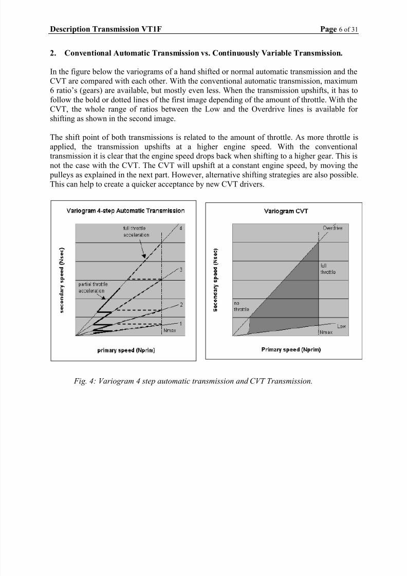
2. Conventional Automatic Transmission vs. Continuously Variable Transmission.
In the figure below the variograms of a hand shifted or normal automatic transmission and the
CVT are compared with each other. With the conventional automatic transmission, maximum
6 ratio’s (gears) are available, but mostly even less. When the transmission upshifts, it has to
follow the bold or dotted lines of the first image depending of the amount of throttle. With theCVT, the whole range of ratios between the Low and the Overdrive lines is available for
shifting as shown in the second image.
The shift point of both transmissions is related to the amount of throttle. As more throttle is
applied, the transmission upshifts at a higher engine speed. With the conventional
transmission it is clear that the engine speed drops back when shifting to a higher gear. This is
not the case with the CVT. The CVT will upshift at a constant engine speed, by moving the
pulleys as explained in the next part. However, alternative shifting strategies are also possible.
This can help to create a quicker acceptance by new CVT drivers.
Fig. 4: Variogram 4 step automatic transmission and CVT Transmission.
7/14/2019 ZF Description VT1F 040323
http://slidepdf.com/reader/full/zf-description-vt1f-040323 7/31
Description Transmission VT1F Page 7 of 31
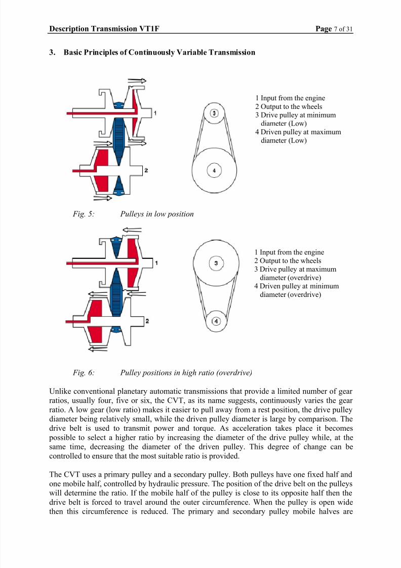
3. Basic Principles of Continuously Variable Transmission
1 Input from the engine2 Output to the wheels3 Drive pulley at minimum
diameter (Low)4 Driven pulley at maximum
diameter (Low)
Fig. 5: Pulleys in low position
1 Input from the engine2 Output to the wheels3 Drive pulley at maximum
diameter (overdrive)4 Driven pulley at minimum
diameter (overdrive)
Fig. 6: Pulley positions in high ratio (overdrive)
Unlike conventional planetary automatic transmissions that provide a limited number of gear
ratios, usually four, five or six, the CVT, as its name suggests, continuously varies the gear ratio. A low gear (low ratio) makes it easier to pull away from a rest position, the drive pulley
diameter being relatively small, while the driven pulley diameter is large by comparison. The
drive belt is used to transmit power and torque. As acceleration takes place it becomes
possible to select a higher ratio by increasing the diameter of the drive pulley while, at the
same time, decreasing the diameter of the driven pulley. This degree of change can be
controlled to ensure that the most suitable ratio is provided.
The CVT uses a primary pulley and a secondary pulley. Both pulleys have one fixed half and
one mobile half, controlled by hydraulic pressure. The position of the drive belt on the pulleys
will determine the ratio. If the mobile half of the pulley is close to its opposite half then the
drive belt is forced to travel around the outer circumference. When the pulley is open wide
then this circumference is reduced. The primary and secondary pulley mobile halves are

7/14/2019 ZF Description VT1F 040323
http://slidepdf.com/reader/full/zf-description-vt1f-040323 8/31
Description Transmission VT1F Page 8 of 31
diagonally opposed so when the drive belt diameter is reduced on the primary pulley, it
increases on the secondary pulley.
To pull away, a low ratio is required. To provide this, the primary pulley is open, allowing the
drive belt to sit down into the pulley and forcing it to run around the outer of the closed
secondary pulley. As vehicle speed increases, a higher gear ratio is required. To do this, the primary pulley gradually moves towards its fixed partner, increasing the pulley
circumference. At the same time the secondary pulley is forced apart reducing pulley
diameter, therefore creating a higher gear ratio. An overdrive ratio is obtained when the
primary pulley is fully closed and the secondary pulley is fully open. The secondary pulley is
now forced to rotate approximately two and a half time for every turn of the primary pulley.
4. Shift Positions.
Possible shift positions for the VT1F are Park, R everse, Neutral, Drive and S port/Manual
position (other shifter lay outs are also possible of course, for instance with an L position).
In the Drive position, the car will move forwards in standard CVT mode. The engine speed
will be limited to approximately 4500 rpm unless kick down is used by fully depressing the
throttle pedal when the engine speed will rise to approximately 5500 rpm. Of course other
calibrations are also possible.
In the Manual/S port position, the car will move forwards in CVT sport mode. The engine
speed will be limited to approximately 5000 rpm unless kick down is used by fully depressing
the throttle pedal when the engine speed will rise to approximately 5500 rpm. Again, other
calibrations are also possible.
1. Illuminated gear position
2. Gear selector lever
Fig. 7: VT1F gear lever & M+ /-
In S port position the transmission will be tuned in a different way than in Drive mode. The
transmission will upshift at a higher engine speed, providing more sportive driving. The Sport
driving calibration is designed to be more responsive to driver command, but will be less
refined than the D position.

7/14/2019 ZF Description VT1F 040323
http://slidepdf.com/reader/full/zf-description-vt1f-040323 9/31
Description Transmission VT1F Page 9 of 31
If the gear shift lever is moved into the ‘Plus’ or ‘Minus’ position from Manual/S port, the
system will change into Manual mode. The transmission then works with 6 (or more) “gear”
ratios. The system will select a gear appropriate to road and driving conditions. To change up
a gear, the driver must move the gear lever to the ‘Plus’ position. To change down, the driver
must move the gear lever to the ‘Minus’ position.
If the CVT software decides that a shift might cause damage to the transmission, such as
attempting to shift to 1st gear at 100 km/h, the gear change will be prevented. If the driver
does not shift up, the next gear will be automatically selected when the engine revolutions
reach approximately 6000 rpm. Equally, if the driver does not shift down when reducing
vehicle speed, the system performs the down-change automatically thus ensuring the
transmission is in the appropriate gear.
5. Functionality in Park and Neutral
The engine can only be started in Neutral or Park, as with any automatic transmission.
A spring and cone operated pawl mechanically locks the secondary pulley when the selector
lever is moved to the Park position. If the lever is set in the Park position when the vehicle
has a higher speed, the pawl will rattle without engaging Park. It will not engage until the
vehicle speed drops below approximately 5 km/h.
1. Parking pawl
2. Secondary pulley
Fig. 8: Parking lock
6. Normal Operation
The operation of the transmission, during driving, has no comparison with that of a
conventional automatic transmission. All kinds of tunings are possible. A possible tuning is
that if the accelerator pedal is depressed sharply, the engine rpm will rise considerably more
than in relation to the speed of the vehicle. This functionality is normal for a CVT but may
surprise drivers not familiar with this type of transmission. Other tunings / variograms are
also possible, for example tunings that are closer to that of a conventional automatic
transmission.

7/14/2019 ZF Description VT1F 040323
http://slidepdf.com/reader/full/zf-description-vt1f-040323 10/31
Description Transmission VT1F Page 10 of 31
7. Transmission Communication
The VT1F has electronic components to control the gear ratios, the clamping force on the belt
and the clutch pressure. The location of the components that form the steptronic transmission
vary depending upon vehicle installation.
There are different options for the position of electronic components in the transmission. For
example, the control methods associated with the transmission can be run as part of the
software in the ECU. The CVT software in the ECU receives inputs from the main sensors of
this system, communicates with the gearbox interface unit (GIU) to control the transmission,
accepts driver inputs and provides information to the driver via the instrument cluster. With
this example the software is located in the ECU, while the drivers are in the Gearbox Interface
Unit (GIU). It is also possible to put both the software and the drivers in a TCU.
8. Related Car Components
8.1 Centre Console LEDs
The configuration of which controle LEDs are to be used depends on customer.
8.2 Instrument Cluster Display
The same is valid for this part. The Instrument Cluster Display is also defined by the
customer.
8.3 Selector Lever Mechanics
Park, Reverse, Neutral and Drive Switches
The configuration of the selector lever is customer specific. A shift lock (as in the picture
below) must be integrated in the mechanism, to provide an idiot start protection.
1. Gear selector lever
2. Gear selector lever detent
3. Shift lock
4. Gear change selector rod
Fig. 9: VT1F selector lever mechanism

7/14/2019 ZF Description VT1F 040323
http://slidepdf.com/reader/full/zf-description-vt1f-040323 11/31
Description Transmission VT1F Page 11 of 31
8.4 Torsional damper
The engine is connected to the input shaft in the transmission, via a torsional damper, instead
of the torque converter used by more conventional automatic transmissions.
This torsional damper is not a part of the transmission.
1. Drive plate gearbox side
2. Engine side
Fig. 10: Torsional damper
9. Towing of the Vehicle
The VT1F transmission must not be towed. This is because there is no oil pressure in the
primary pulley unless the engine is running and belt slip would therefore occur. Recovery
must be conducted with the front wheels lifted clear of the ground (suspended tow).
With a manual transmission it still is possible to start the car by pushing or towing. This is not possible with the CVT because there will be no oil pressure (as the engine and the pump are
not running) meaning that both clutches are disengaged and that there is no connection
between the engine and wheels.
10. Drain & Refill
A refill of the transmission oil is necessary every 45.000 km.
For this purpose, the gearbox is equipped with an oil drain plug and a top filler plug.

7/14/2019 ZF Description VT1F 040323
http://slidepdf.com/reader/full/zf-description-vt1f-040323 12/31
Description Transmission VT1F Page 12 of 31
II. Transmission Layout
Fig. 11: VT1F transmission Layout

7/14/2019 ZF Description VT1F 040323
http://slidepdf.com/reader/full/zf-description-vt1f-040323 13/31
Description Transmission VT1F Page 13 of 31
The VT1F consists of a number of elements that can be divided into three groups, depending
upon their function.
Group One – Mechanical Torque Flow
Elements providing the mechanical torque flow through the transmission.
Group Two – Control system
These elements relate to the control system. This system enables the transmission to transmit
power and to vary the ratio in a proper way, according to load conditions and driver demand.
Group Three – External Connections
A number of elements have external connections with the transmission. Some of these
elements are either inside the gearbox, or immediately connected to it. Others can be part of
the system, but can be located elsewhere on the vehicle.
1. Group One - Mechanical Torque Flow
1.1 Planetary Gear Set
The planetary gear set enables the transmission to provide a drive torque in two directions,
forward and reverse. Engine torque always enters the transmission through the input shaft of
the planet carrier. This carrier can be directly connected to the sun-wheel by closing the
forward multi-plate clutches. When it does, the epicyclic gear set rotates as one unit, and
engine torque is transmitted directly to the primary pulley. The planet gears do not transmitany torque, therefore no mechanical loss will occur in the planetary gear set and the primary
pulley will rotate in the same direction as the engine. This is the forward drive mode.
Fig. 12: Planet gears
In reverse mode, the annulus of the planetary gear set is held stationary by closing the reverse
multi-plate clutches. Three pairs of planet gears are driven by the planet carrier, forcing the
sun-wheel to rotate in the opposite direction.

7/14/2019 ZF Description VT1F 040323
http://slidepdf.com/reader/full/zf-description-vt1f-040323 14/31
Description Transmission VT1F Page 14 of 31
1. Planet gears
2. Input shaft3. Sun gear
4. Annular gear
Fig. 13: Planet gears
There is a small multiplication of torque being transmitted since the ratio of the epicyclic gear
set is 1:1.1, in order to compensate for frictional losses within the planetary gear set itself.
1.2 Multiplate clutches.
There are two Multiplate wet clutch packs; one forward and one reverse. Each pack has three
friction plates providing six friction surfaces. The hydraulic pressure controls the clutches to
allow the vehicle to move away smoothly by every throttle opening. By controlling the belt
slip it also allows the vehicle to be held stationary after the drive gear is engaged. Oil from the
oil cooler is directed to the clutch plates to prevent overheating of the friction surfaces.
1. Forward clutch pack
2. Reverse clutch pack
Fig. 14: Planetary gear set showing clutch plates

7/14/2019 ZF Description VT1F 040323
http://slidepdf.com/reader/full/zf-description-vt1f-040323 15/31
Description Transmission VT1F Page 15 of 31
1.3 Pulley and Steel Belt
The main design feature of the CVT is a pair of steel "V " shaped pulleys connected by a steel
drive belt. The distance between centres of the primary and secondary pulley is 155 mm. Each
pulley consists of one fixed half and one axially slideable half, both having 11 degree sloping
sides. The proven 24 mm wide "Van Doorne" push type drive belt is used to transfer torque between the pulleys (applications for higher torque values can make use of a 30 mm drive
belt). The belt is lubricated and cooled by an oil jet from a nozzle. Both moving halves are
situated diagonally opposite to each other in order to reduce misalignment of the drive belt
during shifting. Each moving half is connected to a hydraulic cylinder/piston. Hydraulic
pressure is controlled by the control system, described in the section titled ‘Hydraulic
system’. Ball splines prevent the moving halves from rotating relatively to their fixed
partners.
Fig. 15: Steel Drive belt
Torque transmitted by the planetary gear set acts directly onto the primary pulley, as the sun-
wheel is splined to it. The steel drive belt transmits the power from the primary pulley to the
secondary pulley and the power from the secondary pulley is then transmitted to the pinion
shaft.
Torque and speed of the secondary pulley are determined by the position of the drive belt.
The sizes of the two pulleys are designed to provide a range of ratios from 2.416:1 to 0.443:1
resulting in a ratio spread of 5.45. The high overdrive ratio is particularly advantageous in
respect to fuel consumption.
The steel drive belt has approximately 450 segments and is held together by 24 steel bands,
12 on each side. All the segments are of the same thickness.
1. Steel bands
2. Steel segments
Fig. 16: Drive belt

7/14/2019 ZF Description VT1F 040323
http://slidepdf.com/reader/full/zf-description-vt1f-040323 16/31
Description Transmission VT1F Page 16 of 31
1.4 Pinion Shaft
The pinion shaft creates a two-set helical gear reduction between the secondary pulley and the
differential. In this way, the rotational direction of the drive shafts will be correct. The
reduction between the secondary pulley and the drive shafts can be made large enough to give
good vehicle performance. The pinion shaft is supported by two conical bearings, one in theclutch housing and one in a separate bearing support.
1. Primary shaft drive gear
2. Differential crown wheel
3. Pinion drive gear
4. Transfer gear pinion shaft
5. Secondary shaft drive gear
Fig. 17: Crown wheel & pinion
1.5 Differential
Drive torque on the crown wheel is transmitted to the vehicle wheels via a bevel gear
differential, just as in a manual transmission. The crown wheel is bolted to the differentialcase with 8 bolts. The drive shafts are fitted to the differential with conventional CV joints
and seals. Conical bearings are used to support the differential.
1. Differential bearing2. Differential casing
3. Differential cross shaft
4. Differential planet gears
5. Differential crown wheel
Fig. 18: Differential assembly

7/14/2019 ZF Description VT1F 040323
http://slidepdf.com/reader/full/zf-description-vt1f-040323 17/31
Description Transmission VT1F Page 17 of 31
1.6 Mechanical Operation
1.6.1 Selector lever in the park or neutral position
In this condition motion is not transferred to the wheels as both clutches for reverse (2) and
forward gears (4) are disengaged.
- The transmission input shaft (1) turns at the same speed as the engine.
- The reverse gear clutch (2) is disengaged.
- The forward gear clutch (4) is disengaged.
- The planetary gears (3) idle around the sun gear.
- As the sun gear does not move, neither does the primary pulley (5), the secondary pulley
(7) and, subsequently, the vehicle.
1. Input shaft2. Reverse gear clutches
3. Planetary gears
4. Forward gear clutches
5. Primary pulley
6. Steel drive belt
7. Secondary pulley
Fig. 19: Pulleys & gear train
7/14/2019 ZF Description VT1F 040323
http://slidepdf.com/reader/full/zf-description-vt1f-040323 18/31
Description Transmission VT1F Page 18 of 31
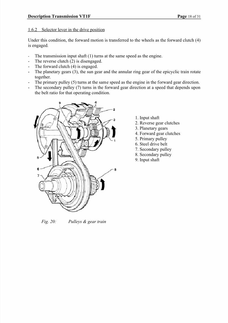
1.6.2 Selector lever in the drive position
Under this condition, the forward motion is transferred to the wheels as the forward clutch (4)
is engaged.
- The transmission input shaft (1) turns at the same speed as the engine.- The reverse clutch (2) is disengaged.
- The forward clutch (4) is engaged.
- The planetary gears (3), the sun gear and the annular ring gear of the epicyclic train rotate
together.
- The primary pulley (5) turns at the same speed as the engine in the forward gear direction.
- The secondary pulley (7) turns in the forward gear direction at a speed that depends upon
the belt ratio for that operating condition.
1. Input shaft
2. Reverse gear clutches
3. Planetary gears
4. Forward gear clutches
5. Primary pulley
6. Steel drive belt
7. Secondary pulley
8. Secondary pulley
9. Input shaft
Fig. 20: Pulleys & gear train

7/14/2019 ZF Description VT1F 040323
http://slidepdf.com/reader/full/zf-description-vt1f-040323 19/31
Description Transmission VT1F Page 19 of 31
1.6.3 Selector lever in the reverse position
Under this condition, the reverse clutch (2) is engaged and makes the annular ring gear (9)
lock to the transmission case. The planetary gears (3) force the sun gear (10), the primary
pulley (5) and the secondary pulley (7) to turn in the opposite direction to the transmission
input shaft (1). Therefore reverse gear is now selected.
- The transmission input shaft (1) turns at the same speed as the engine.
- The reverse clutch (2) is engaged.
- The forward clutch (4) is disengaged.
- The annular gear (9) is linked with the transmission case by means of the reverse clutch
(2).
- The planetary gears (3), which are driven directly by the transmission input shaft (1), turn
around the annular gear (9). Therefore they force the sun gear (10), the pulley (5) and the
secondary pulley (7) to turn in the reverse gear direction.
1. Input shaft
2. Reverse gear clutches
3. Planetary gears
4. Forward gear clutches
5. Primary Pulley
6. Steel drive belt
7. Secondary pulley
8. Secondary pulley
9. Annular gear 10. Sun gear
Fig. 21: Pulleys & gear train

7/14/2019 ZF Description VT1F 040323
http://slidepdf.com/reader/full/zf-description-vt1f-040323 20/31
Description Transmission VT1F Page 20 of 31
2. Group Two - Control System
The functions of the control system are:
1. To match the clamping force on the steel drive belt tension with engine torque, preventing
belt slip.
2. To control the operation of the forward and reverse clutches during driving and take off.
3. To provide the optimum transmission ratio for all driving conditions.
4. Provide the necessary lubrication and cooling oil in the gearbox.
5. Provide the required oil supply for the pitot systems.
2.1 Oil Pump
The pump within the transmission is an external gear pump. The engine drives it via a shaft
through the hollow primary pulley shaft. The pump shaft is splined to the planet carrier,
which always run at engine speed. The discharged volume is about 10 cm3 per revolution.
System pressure can reach 40 to 50 bar depending on input torque.
1. Oil pump drive shaft
2. Oil pump assembly
Fig. 22: Oil pump complete
The oil pressure is used both for controlling the transmission hydraulically, and for lubrication
purposes.
1. Oil pump inlet
2. Oil pump oil seals
Fig. 23: Oil pump inlet

7/14/2019 ZF Description VT1F 040323
http://slidepdf.com/reader/full/zf-description-vt1f-040323 21/31
Description Transmission VT1F Page 21 of 31
2.2 Valves
The CVT is controlled by a number of valves that respond to mechanical, electrical and
hydraulic inputs. Basically, the control system is designed to control the ratio, the clamping
force and the clutches in the following four ways:
1. Flow to and from the primary pulley is controlled to command the correct transmission
ratio for all driving conditions. In this range a primary valve and a linear actuator is used.
2. Pressure is supplied to the secondary pulley to ensure that there is always adequate
clamping force onto the belt for all load conditions. A solenoid valve influences the
secondary pressure control valve, optimising the pressure and hence the clamping force.
Optimisation of this pressure improves fuel consumption. The working valves in this area
are the secondary valve, the exhaust secondary valve, and a PWM solenoid secondary
valve.
3. Selection of the correct clutch (forward or reverse). Engagement of forward or reverse
gear via the selector mechanism operates the manual valve directing oil to the appropriate
clutch. For this functions there is a manual valve and a reverse inhibitor valve.4. Control of the operation needed for take off: A solenoid valve acting on the clutch valve
controls the clutch application pressure to ensure smooth clutch engagement and drive
away at all throttle openings. Here a clutch valve, an exhaust valve clutch pressure, a
constant pressure valve, the supply valve and the PWM solenoid clutch valve are used.
There also is a cooler flow valve that controls the oil flow through the cooler.
2.3 Pitot system
The engine speed and the drive mode are used for controlling the clutch engagement. The
speed dependent signals are provided by two ‘pitot’ systems. Each consists of a pitot chamber
and a pitot pipe. The pipe is stationary, while the chamber, which is filled with oil, is rotating
at the speed to be measured.
1. Pitot tube
2. Oil pump3. Pitot tube
4. Pitot chamber
Fig. 28: Pitot tube ghosted inside cover

7/14/2019 ZF Description VT1F 040323
http://slidepdf.com/reader/full/zf-description-vt1f-040323 22/31
Description Transmission VT1F Page 22 of 31
A hydraulic pressure, proportional to speed, is detected at one end of the pipe, which is
dipped in the rotating oil ring inside the pitot chamber. These pressures act on the primary,
secondary and clutch valves inside the control unit, influencing transmission operation.
2.4 Sensing shoe
The sensing shoe is a mechanism that measures the position of the pulleys. The sensing shoe
acts via a rocker onto the secondary valve spring within the hydraulic control unit, controlling
the clamping force. The clamping force can be decreased when the transmission up-shifts, as
the drive belt will run on a bigger radius around the primary pulley. With the drive belt
running in an overdrive situation, a lower secondary pressure will still create enough
clamping force to transmit the torque.
1. Sensing shoe
2. Pulley
Fig. 29: Sensing shoe in box
1. Sensing shoe shaft
2. Sensing shoe
3. Sensing shoe
locking bolt
position
Fig. 30: Photo sensing shoe
2.5 Oil Temperature Sensor
The oil temperature sensor is a two wire sensor and is located in the valve block area.
The sensor continuously monitors the temperature of the oil. Should the oil temperature rise
above preset parameters, the ECU will reduce the amount of slip within the clutch to reduce
the oil temperature.

7/14/2019 ZF Description VT1F 040323
http://slidepdf.com/reader/full/zf-description-vt1f-040323 23/31
Description Transmission VT1F Page 23 of 31
3. Group Three - External Connections
Each element of group three will now be described.
3.1 Park/Neutral Switch
The selector cam activates the park/neutral switch, which prevents the car from starting in
reverse, drive or sport, and switches on the reverse lights when in reverse. The switch also
sends its position to the CVT Software in the ECU that uses this switch in conjunction with
the gear selector switch to establish the correct driving mode.
Fig. 31: Park/Neutral switch
1. Park/Neutral switch
plunger
2. Selector cam
Fig. 32: Switch & selector mechanism
When the selector lever is in the park or neutral position and the ignition is switched on, the
CVT software in the ECU will energise a shift lock solenoid on the selector lever in the car.
This locks the lever in the park or neutral position. The selector lever cannot be moved from
the park or neutral position until the footbrake is applied.

7/14/2019 ZF Description VT1F 040323
http://slidepdf.com/reader/full/zf-description-vt1f-040323 24/31
Description Transmission VT1F Page 24 of 31
3.2 Oil Cooler Locations
There are two oil cooler pipe connections on the front of the transmission casing. An oil
cooler is fitted alongside the radiator to maintain the transmission oil temperature between
80°C and 120°C.
1. Oil cooler pipe inlet
2. Oil cooler pipe outlet
Fig. 33: Oil cooler pipe position

7/14/2019 ZF Description VT1F 040323
http://slidepdf.com/reader/full/zf-description-vt1f-040323 25/31
Description Transmission VT1F Page 25 of 31
3.3 Transmission Secondary Speed Sensor
The VT1F transmission has a dedicated secondary speed sensor located in the differential
housing. The sensor is located at the crown wheel. This sensor is a Hall effect sensor and
produces a pulse train of 81 pulses per rotation. The sensor allows for more precise
calculation of transmission output speed that is used in the control strategy systems.
Fig. 34: Secondary speed sensor in gearbox
1. Speed sensor
2. Speed sensor oil seal
Fig. 35: Secondary speed sensor

7/14/2019 ZF Description VT1F 040323
http://slidepdf.com/reader/full/zf-description-vt1f-040323 26/31
Description Transmission VT1F Page 26 of 31
3.4 Selector Shaft
Selection of the required driving mode, through the selector lever inside the vehicle, activates
a selector shaft within the transmission. A push/pull type cable connects the lever in the car
and the shaft on the gearbox.
1. Retaining clip
2. Protection cover
3. Gear change rod
4. Gear change lever
Fig. 36: Gear selection cable to gearbox rod
1. Selector shaft
Fig. 37: Gear selector rod in box
3.5 Connector
The connector consists of 16 pins and is located in the transmission casing. The harnessconnection is via a circular connector.
Fig. 38: Harness block on gearbox

7/14/2019 ZF Description VT1F 040323
http://slidepdf.com/reader/full/zf-description-vt1f-040323 27/31
Description Transmission VT1F Page 27 of 31
III. Strategies
1. Behaviour in Specific Situations
The behaviour of a vehicle, fitted with CVT, will now be discussed in the following specific
situations:
1.1 Idle While Drive is Selected
When the engine is started and drive selected without depressing the throttle pedal primary
pitot pressure will be very low. There is no primary pressure and the belt is positioned on its
lowest primary radius. The clutch valve determines the creep behaviour of the car with the
engine running at idle. The cooler valve sends the coldest oil to the drive clutch.
1.2 Take Off/Pulling Away
The position of the throttle pedal determines at which speed the transmission will up-shift.
This is also dependent on which drive mode is selected (Drive, Sport or Manual). Pushing the
throttle pedal down will result in the following actions:
- As the engine speed increases so does the engine pitot pressure and the clutch pressure.
- If the clutch pressure becomes too high it will bleed into the exhaust valve clutch pressure.
The bleeding of the clutch pressure is set so that the full engine torque can be transmitted
at any time. Via the forward clutch, the primary pulley starts accelerating and the primary
pitot pressure rises. It is this pressure that prevents reverse gear from being accidentally
selected. At a specific speed the primary pressure rises and the primary pulley halves are pushed towards each other increasing the primary radius of the belt. As the belt is of a
constant length the secondary pulley halves must widen accordingly.
- The transmission will up-shift at a constant engine speed until overdrive is reached. This
strategy is only used to show the possibilities of a CVT. Other strategies with an engine
speed that rises with the vehicle speed are also possible. Under constant conditions the
speed of the vehicle will stabilise. If the load should increase, for example driving uphill,
and the driver does not change the position of the throttle pedal, then the transmission
automatically downshifts. The gradient makes the secondary speed drop. The primary
speed wants to stay constant and the primary valve regulates the primary pressure in such
a way that the engine speed does not change. Thus the primary pulley halves will widenand the primary radius of the belt will decrease. The secondary belt radius will increase
because of the fixed belt length. The transmission has downshifted, and the engine speed
stays the same but vehicle speed has dropped.
1.3 Light Throttle Acceleration in Drive or Sport
The driver is at a fixed point in overdrive. Assuming the primary belt radius would be at a
maximum, the secondary at a minimum. Light acceleration, by using the throttle pedal, will
activate the ratio control motor acting upon the primary valve causing the primary pressure to
drop. The transmission will downshift slightly, which will result in higher pitot pressure and
balance within the primary valve restored. The transmission up-shifts at the new constantengine rpm.

7/14/2019 ZF Description VT1F 040323
http://slidepdf.com/reader/full/zf-description-vt1f-040323 28/31
Description Transmission VT1F Page 28 of 31
1.4 Kick-Down in Drive or Sport
Fully depressing the throttle pedal will move the primary valve and the primary pressure will
rapidly drop. The transmission shifts down as far as possible. The sensor shoe on the primary
pulley creates a high spring force onto the secondary valve; therefore, the secondary pressureis kept at a sufficient high level to avoid belt slip. The balance in the primary valve can only
be restored with a higher engine speed.
1.5 Emergency Stop
During design care has to be taken so that the vehicle, after an emergency stop, can take off
again immediately. During an emergency stop situation the transmission has to downshift
very quickly. The chamber on the secondary pulley must be filled very quickly to push the
secondary pulley halves towards each other and to clamp the belt. The most critical situation
is an emergency stop from a minimum engine speed. The required pump flow increases with
the amount of braking.
The speed of the engine can only be held constant when the transmission has the time to
downshift. This can cause some problems when braking on a slippery surface, for example,
on ice, as the wheels will lock very fast. The clamping force and the locked clutches make the
engine speed decrease very fast, to a speed at which the clutche disengages, bringing the
pulleys to a standstill. In the primary valve the primary pressure is bleeding as there is no pitot
pressure. Due to secondary pressure, the transmission down-shifts, although the shift time will
be greater as the pulleys are standing still. This enables the transmission to be in a low ratio
when the vehicle comes to a halt.
1.6 Reverse Running
With the manual valve in reverse, the clutch pressure will be sent to the reverse clutch via the
reverse inhibitor valve. Once the vehicle is running in reverse, the clutch will stay under
pressure because the primary pitot tube opening is in opposite direction to the oil flow within
the pitot chamber, and therefore can sense no pressure. This keeps the reverse inhibitor valve
in balance in the open position. Consequently the primary pressure will be bleeding and thetransmission will stay in a low ratio.
1.7 Fault Mode
If the software detects an error within the system, a default strategy will be engaged. These
conditions are communicated to the driver via the fault indication in the instrument cluster.
Depending on the severity of the fault, the driver will experience different default driving
modes.
If the system is still able to control the transmission ratio, the standard limp-home is used to
default the gearbox so that the shift up speed is fixed. This will protect the transmission under
all driving conditions. Under most driving conditions, the astute driver will notice that the
engine speed is hanging around 3000 rpm at most road speeds.

7/14/2019 ZF Description VT1F 040323
http://slidepdf.com/reader/full/zf-description-vt1f-040323 29/31
Description Transmission VT1F Page 29 of 31
The most serious fault will cause the transmission to be stuck in a single gear ratio. If stuck in
the lowest gear, the driver will see the engine speed quickly increase to 6000 rpm and stay
there. The maximum possible vehicle speed is approximately 50 km/h. If stuck in the highest
gear, the driver will experience very sluggish acceleration and engine speeds hanging around
2000 to 2250 rpm at vehicle speeds of up to 80 km/h.
The software can instruct the instrument cluster to display an error code, or the Engine MIL
depending on legislative requirements.
There are certain faults that the software will not default the transmission into its limp home
position.
These are:
1. Gear lever + switch failure.
2. Gear lever - failure.
3. Shift interlock system fault.4. Centre Console LED fault.
Limp home position is not necessary for these failures because the control of the gearbox is
not compromised; it is only necessary to warn the driver.
The ECU / TCU will not operate the sequential gear changes in manual mode if these
switches are faulty.
2. CVT Software
The CVT software is incorporated into the CVT software either in the ECU or the TCU. The
software does not control the transmission ratio directly but does provide all of the
intelligence relating to the required position of the ratio control motor. It also provides the
intelligence for how fast it should be operated.
The ECU or the TCU controls the transmission in one of the following modes. Again, extra
modes (economy, comfort, winter, …) could be integrated too:
1. Drive mode (normal CVT driving).
2. S port CVT mode or Low CVT mode.
3. Manual mode.4. Fault mode.
5. R everse mode
In the CVT modes, the control system operates by deriving a target engine speed based on
current vehicle speed and driver demand. In manual mode, the system derives a target engine
speed based on the vehicle speed and the current gear ratio. Having obtained an engine speed
target, the system calculates the appropriate ratio control motor position and instructs the GIU
or the drivers in the TCU to deliver this position.
The ECU / TCU also needs to control the speed of the ratio control motor in order to protect
the transmission from damage due to drive belt slippage.

7/14/2019 ZF Description VT1F 040323
http://slidepdf.com/reader/full/zf-description-vt1f-040323 30/31
Description Transmission VT1F Page 30 of 31
The software in the ECU / TCU also knows the maximum torque that the belt can transfer
across all possible ratio ranges. It is extremely important that the belt does not slip on the
pulleys, as this would cause excessive wear.
3. Transmission Reset and Reference
The CVT software in the ECU / TCU controls the position of the ratio motor. It does this by
sending the exact position (in steps) it wishes the GIU / driver to set the stepper motor. The
software then monitors the engine speed to ensure that the engine speed has altered in
accordance with the expectations. If the engine speed does not follow the expectations it is
assumed that the GIU / driver has lost its position reference of the stepper motor. When this
loss of position happens the software orders a reset. The GIU / driver then resets it’s internal
position counter to that of the ECU / TCU. The ECU /TCU will also stop any learning for that
ignition cycle.
The ECU completes a reference every time the ignition is switched ‘off’ or ‘on’. These two
references are different because of the need to set the transmission in the appropriate position.

7/14/2019 ZF Description VT1F 040323
http://slidepdf.com/reader/full/zf-description-vt1f-040323 31/31
Description Transmission VT1F Page 31 of 31
IV. Adaptation Procedures
Due to manufacturing tolerances in the transmission, and since the VT1F system is subject to
many strict legislative requirements, it is essential to put the control system through a learning
procedure, before the transmission can be controlled effectively.
On the completion of the adaptation, the lifetime adaptation strategy will commence; fine
tuning the response of the control system for the transmission attached to a particular vehicle.
If either the ECU / TCU, GIU / driver or transmission is changed during the service life of the
vehicle, the adaptation strategies must be reset, which in turn will reset the lifetime strategy so
it starts learning from the new base point.