zelio control measurement relays
TRANSCRIPT

File 8430
Zelio® Control Measurement RelaysRM4 and RM84
CONTENTS
RM4 Application Data . . . . . . . . . . . . . . . . . . . . . . . . . . . . . . . . . . . . . . . . . 2RM4JA Current Measurement Relays . . . . . . . . . . . . . . . . . . . . . . . . . . . . . 4RM84871 Current Measurement Relays . . . . . . . . . . . . . . . . . . . . . . . . . . 10RM4UA Voltage Measurement Relays. . . . . . . . . . . . . . . . . . . . . . . . . . . . 14RM84872 Voltage Measurement Relays . . . . . . . . . . . . . . . . . . . . . . . . . . 20RM4T Three-Phase Monitoring Relays . . . . . . . . . . . . . . . . . . . . . . . . . . . 28RM84873 Three-Phase Monitoring Relays . . . . . . . . . . . . . . . . . . . . . . . . 34RM4UB Single-Phase Monitoring Relays . . . . . . . . . . . . . . . . . . . . . . . . . 46RM4L Liquid Level Relays . . . . . . . . . . . . . . . . . . . . . . . . . . . . . . . . . . . . . 49RM84870 Liquid Level Relays . . . . . . . . . . . . . . . . . . . . . . . . . . . . . . . . . . 54RM79 Liquid Level Probes . . . . . . . . . . . . . . . . . . . . . . . . . . . . . . . . . . . . . 66RM84874 Underspeed Relays. . . . . . . . . . . . . . . . . . . . . . . . . . . . . . . . . . 68RM84873 Motor Load Relays . . . . . . . . . . . . . . . . . . . . . . . . . . . . . . . . . . 70Index of Catalog Numbers . . . . . . . . . . . . . . . . . . . . . . . . . . . . . . . . . . . . . 74
CatalogJune
05
Courtesy of Steven Engineering, Inc.-230 Ryan Way, South San Francisco, CA 94080-6370-Main Office: (650) 588-9200-Outside Local Area: (800) 258-9200-www.stevenengineering.com

2© 1996–2005 Schneider Electric All Rights Reserved 6/2005
Zelio® Control Measurement Relays RM4 Application Data
Application Data
Conforming to Standards IEC 60255-6, EN 60255-6
Product Approvals
CE Marking Zelio-Control measurement relays conform to European regulations relating to CE Marking.
Ambient Air TemperatureAround the Device
Storage -40 to 185 °F (-40 to +85 °C)
Operation -4 to 149 °F (-20 to +65 °C)
Permissible Relative Humidity Range Conforming to IEC 60721-3-3 15 to 85% Environmental class 3K3
Vibration Resistance Conforming to IEC 60068-2-6, 10 to 55 Hz a = 0.35 ms
Shock Resistance Conforming to IEC 60068-2-27 15 gn, 11 ms
Degree of ProtectionHousing IP 50
Terminals IP 20
Degree of Pollution Conforming to IEC 60664-1 3
Overvoltage Category Conforming to IEC 60664-1 III
Rated Insulation Voltage
Between contact circuit and power supply, or between contact circuit and control inputs
Conforming to IEC 500 V
Conforming to CSA, UL 500 V
Test Voltage forInsulation Tests
Dielectric test UL Hipot at 2,200 V (IEC 2,500 V)
Shock wave 4.8 kV
Voltage Limits Power supply circuit 0.85–1.1 Uc ▲
Disconnection Value Power supply circuit > 0.1 Uc
Mounting Positionwithout Derating
In relation to the normal vertical mounting position Any position
Connection Maximum Cross-Section
Stranded wire without cable end Two #14 AWG (2.5 mm2)
Stranded wire with cable end Two #16 AWG (1.5 mm2)
Tightening Torque 4.5–9.9 lb-in (0.5–1.1 N●m)
Mounting Can be mounted directly to a panel or on a 1.38 in. (35 mm) wide by 0.29 in. (7.5 mm) or 0.59 in. (15 mm) depth mounting track.
Immunity from Electromagnetic Interference (EMC) (Application Class 2 Conforming to EN 61812-1)
Electrostatic Discharge Conforming to IEC 61000-4-2 Level 3 (6 kV contact, 8 kV air)
Electromagnetic Fields Conforming to IEC 61000-4-3 Level 3 (10 V/m)
Rapid Transients Conforming to IEC 61000-4-4 Level 3 (2 kV output power, 1 kV control)
Shock Waves Conforming to IEC 61000-4-5 Level 3 (2 kV common mode, 1 kV differential mode)
Radiated and Conducted Emissions
CISPR11 Group 1 Class A
CISPR22 Class A
▲ Except RM4T, see page 31.
gn = gravitational unit = 9.8 m/s2
®
File E164353CNN NKCR
File LR 89150Guide 3211 07 GL
Courtesy of Steven Engineering, Inc.-230 Ryan Way, South San Francisco, CA 94080-6370-Main Office: (650) 588-9200-Outside Local Area: (800) 258-9200-www.stevenengineering.com

Zelio® Control Measurement RelaysRM4 Application Data
36/2005 © 1996–2005 Schneider Electric All Rights Reserved
Output Relay Specifications
Mechanical Durability ■ In millions of operating cycles 30 ■
Current Limit Ith 8 A
Rated Operational Limits at 158 °F (70 °C)
Conforming to IEC 60947-5-1/1991and VDE 0660
24 V 115 V 250 V
AC-15 3 A 3 A 3 A
DC-13 2 A 0.3 A 0.1 A
UL and CSA Current Ratings Resistive Rating 5 A
(NEMA/UL B300) Inductive Rating3600 VA Make Rating360 VA Break Rating5 A Carry
Minimum Switching Capacity 12 V/10 mA
Switching VoltageRated 250 Vac
Max. 440 Vac
Contact Material Silver Nickel 90/10
■ The product life expressed above is based on average usage and and normal operating conditions. Actual operating life will vary with conditions. The above statements are not intended to nor shall they create any expressed or implied warranties as to product operation or life. For information on the listed warranty offered on this product, refer to the Square D terms and conditions of sale found in the Digest.
◆ When used with a DC contactor, it is recommended that a free-wheel diode be connected in parallel on the coil.
q Curve 2 based on 35% power factor.
10
1
0.1
0.010 1 2 3 4 5 6 7 8
Resistive Load (Amperes)
Op
era
ting
Cyc
les
(Mill
ion
s o
f O
pe
ratio
ns)
1
0.6
0.5
0.9
0.8
0.7
0.4
0.31 0.8 0.6 0.5 0.4 0.3 0.2
COS ϕ
Red
uctio
n F
acto
r k
300
40
30
200
100
50
20
100.1 0.2 0.5 1 2 5 2010
1
2
3
Vol
tage
Amperes
RM4
K
+
–
Curve 1 AC Load
Electrical durability of contacts on resistive load in millions of operating cycles ■
Curve 2q
Reduction factor k for inductive loads (applies to values taken from the durability curve opposite) ■
DC LoadLoad Limit Curve ■
Example:
An LC1F185 contactor supplied with 115 V/50 Hz for a consumption of 55 VA or a current consumption equal to 0.1 A and cos ϕ = 0.3.
For 0.1 A, Curve 1 indicates a durability of approximately1.5 million operating cycles.
As the load is inductive, it is necessary to apply a reduction coefficient k to this number of cycles, as indicated by curve 2.
For cos ϕ = 0.3: k = 0.6
The electrical durability therefore becomes: 1.5 × 10⁶ operating cycles × 0.6 = 900,000 operating cycles.
1 L/R = 20 ms
2 L/R with load protection diode
3 Resistive load
Courtesy of Steven Engineering, Inc.-230 Ryan Way, South San Francisco, CA 94080-6370-Main Office: (650) 588-9200-Outside Local Area: (800) 258-9200-www.stevenengineering.com

4© 1996–2005 Schneider Electric All Rights Reserved 6/2005
Zelio® Control Measurement Relays RM4JA Current Measurement Relays
FUNCTIONS
These devices detect when the current level on an AC or DC supply exceeds a pre-set threshold. They have a transparent, hinged cover on the front face to prevent accidental alteration of the settings. This cover can be sealed.
Catalog Number Overcurrent ControlOvercurrent or
Undercurrent Control ■ Measuring Range
RM4JA01 Yes No 3 mA to 1 A
RM4JA31 Yes Yes 3 mA to 1 A
RM4JA32 Yes Yes 0.3 A to 15 A
Applications
• Excitation control of DC machines
• Controlling the load state of motors and generators
• Controlling current drawn by a three-phase motor
• Monitoring heating or lighting circuits
• Controlling pump draining (undercurrent)
• Controlling overtorque (crushers)
• Monitoring electromagnetic brakes or clutches
1 Adjustment of current threshold as a percentage of the setting range maximum value.
2 Hysteresis adjustment from 5 to 30% ▲.
3 Fine adjustment of time delay as a percentage of the setting range maximum value.
4 10-position switch combining
— selection of the timing range: 1 s, 3 s, 10 s, 30 s, no time delay.— selection of overcurrent (>) or undercurrent (<) detection. See table below.
R Yellow LED: indicates relay state (Off for de-energized relay, On for energized).
U Green LED: indicates that supply to the RM4 is present.
Detailed Positions for Switch 4
Switch Position Function Time Delay (t)
< 0 Undercurrent detection No time delay
< 1 Undercurrent detection 0.05 to 1 s
< 3 Undercurrent detection 0.15 to 3 s
< 10 Undercurrent detection 0.5 to 10 s
< 30 Undercurrent detection 1.5 to 30 s
> 0 Overcurrent detection No time delay
> 1 Overcurrent detection 0.05 to 1 s
> 3 Overcurrent detection 0.15 to 3 s
> 10 Overcurrent detection 0.5 to 10 s
> 30 Overcurrent detection 1.5 to 30 s
■ Selection by switch on front face.
▲ Value of current difference between energization and de-energization of the output relay (% of the current threshold to be measured).
RM4JA01
RM4JA32
1234
RU
1234
RU
RM4JA01
Width 0.89 in (22.5mm)
RM4JA31
Width 0.89 in (22.5mm)
RM4JA32
Width 1.77 in (45mm)
12
RU
Courtesy of Steven Engineering, Inc.-230 Ryan Way, South San Francisco, CA 94080-6370-Main Office: (650) 588-9200-Outside Local Area: (800) 258-9200-www.stevenengineering.com

Zelio® Control Measurement RelaysRM4JA Current Measurement Relays
56/2005 © 1996–2005 Schneider Electric All Rights Reserved
OPERATING PRINCIPLE
The supply voltage is connected to terminals A1–A2. The current to be monitored is connected to terminals B1, B2, or B3 (depending on the current range) and C. See the diagram below.
Hysteresis (h) is adjustable between 5 and 30%. For overcurrent, h = (IS1 – IS2)/IS1; for undercurrent,h = (IS2 – IS1)/IS2. A measuring cycle lasts only 80 ms, allowing rapid detection of changes in current.
Overcurrent detection (RM4JA01 or selector on “>” for model RM4JA3•). When the current level exceeds the threshold setting (IS1), the output relay is energized (with or without a time delay, depending on the model). When the current returns to a value (IS2) below the threshold, the relay is instantaneously de-energized. The value of IS2 depends on the hysteresis setting.
Undercurrent detection (selector on “<” for model RM4JA3• only). When the current falls below the threshold setting (IS1), the output relay is energized (with or without a time delay, depending on the model). When the current returns to a value (IS2) above the threshold, the relay is instantaneously de-energized. The value of IS2 depends on the hysteresis setting.
Function Diagrams:
Overcurrent Detection
Undercurrent Detection
NOTE: The measurement ranges can be extended using a current transformer whose secondary is connected to the terminals of the corresponding RM4 relay, or using a resistor connected in parallel with the measuring input (see the example on page 8).
t < t
IS1IS2
15-1815-16
25-2825-26
A1-A2U supply
Current measured
Relay
t: time delay
t < t
IS1IS2
15-1815-16
25-2825-26
A1-A2U supply
Current measured
Relay
t: time delay
B1, B2, B3RM4JA
C
Load
Mea
sure
men
t Circ
uit
Courtesy of Steven Engineering, Inc.-230 Ryan Way, South San Francisco, CA 94080-6370-Main Office: (650) 588-9200-Outside Local Area: (800) 258-9200-www.stevenengineering.com

6© 1996–2005 Schneider Electric All Rights Reserved 6/2005
Zelio® Control Measurement Relays RM4JA Current Measurement Relays
SPECIFICATIONS
Power Supply Circuit SpecificationsType of Relay RM4JA01 RM4JA31 and RM4JA32
Rated SupplyVoltage (Un)
Vac 50/60 Hz 24 110–130 220–240 24–240 110–130 220–240 380–415
Vdc – – – 24–240 – – –
Average Consumption at Un
VA (Vac) 2 1.9–3.3 2.7–3.5 1.5–3.3 1.9–3.3 2.7–3.4 2.7–3
W (Vdc) – – – 1.2 – – –
Output Relay and Operating SpecificationsType of Relay RM4JA01 RM4JA31 and RM4JA32
Number of C/O Contacts
SPDT1 2
Output Relay StateEnergized when:current measured > threshold setting
Energized when:current measured > threshold setting (“>” function)current measured < threshold setting (“<” function)
Switching Threshold Setting Accuracy As a percentage of the full scale value: ±5%
Switching Threshold Drift≤ 0.06% per °C, depending on the permissible ambient temperature
≤ 0.5%, within the supply voltage range (0.85–1.1 Un)
Hysteresis (adjustable) 5–30% of the current threshold setting
Time Delay Setting Accuracy As a percentage of the full scale value: ±10%
Time Delay Drift –≤ 0.07% per °C, depending on temperature
≤ 0.5%, within the supply voltage range (0.85–1.1 Un)
Measuring Cycle ≤ 80 ms
Measuring Input SpecificationsInternal Input Resistance and Permissible Overload Depending on the Current Measurement Ranges
Type of Relay RM4JA01 and RM4JA31 RM4JA32
Measurement Range50–60 Hz Vac/Vdc 3–30 mA 10–100 mA 0.1–1 A 0.3–1.5 1–5 A 3–15 A
Internal Input Resistance Ri 33 Ω 10 Ω 1 Ω 0.06 Ω 0.02 Ω 0.006 ΩPermissible Continuous Overload 0.05 A 0.15 A 1.5 A 2 A 7 A 20 A
Permissible Non-Repetitive Overload for t ≤ 3 s 0.2 A 0.5 A 5 A 10 A 15 A 100 A
SELECTION
Current Measurement Relays: Overcurrent Detection
Time DelayCurrent to be Measured Depending on ConnectionVac or Vdc
Widthin. (mm) Output Relay Supply Voltage
50/60 HzCatalog Number
Weightlb (kg)
None3–30 mA 10–100 mA0.1–1 A
0.87 in. (22.5 mm)
1 C/O–SPDT 24 Vac RM4JA01B 0.38 (0.172)
110–130 Vac RM4JA01F 0.38 (0.172)
220–240 Vac RM4JA01M 0.38 (0.172)
Current Measurement Relays: Overcurrent or Undercurrent Detection
Adjustable Time Delay
Current to be Measured Depending on ConnectionVac or Vdc
Widthin (mm) Output Relay Supply Voltage
50/60 HzCatalog Number
Weight lb (kg)
0.05–30 s
3–30 mA 10–100 mA0.1–1 A
0.87 in. (22.5 mm)
2 C/O–DPDT 24–240 Vac/Vdc RM4JA31MW 0.38 (0.172)
110–130 Vac RM4JA31F 0.38 (0.172)
220–240 Vac RM4JA31M 0.38 (0.172)
380–415 Vac RM4JA31Q 0.38 (0.172)
0.3–1.5 A 1–5 A3–15 A
1.77 in. (45 mm)
2 C/O–DPDT 24–240 Vac/Vdc RM4JA32MW 0.45 (0.204)
110–130 Vac RM4JA32F 0.45 (0.204)
220–240 Vac RM4JA32M 0.45 (0.204)
380–415 Vac RM4JA32Q 0.45 (0.204)
For additional application data, refer to page 2.
RM4JA01
RM4JA32
Courtesy of Steven Engineering, Inc.-230 Ryan Way, South San Francisco, CA 94080-6370-Main Office: (650) 588-9200-Outside Local Area: (800) 258-9200-www.stevenengineering.com

Zelio® Control Measurement RelaysRM4JA Current Measurement Relays
76/2005 © 1996–2005 Schneider Electric All Rights Reserved
DIMENSIONS (approximate)
WIRING
Connection and current values to be measured, depending on type of RM4JA
RM4JA01 and RM4JA31
A1–A2 Supply voltage B1, B2, B3, C Currents to be measured (see table to right)
B1–C 3–30 mA RM4JA32 B1–C 0.3–1.5 A
B2–C 10–100 mA B2–C 1–5 A
B3–C 0.1–1 A B3–C 3–15 A
Application Diagrams
Example: Detection of a blockage on a crusher (overcurrent function)
Current measured ≤ 15 A Current measured > 15 A
3.1580
0.8922.5
3.5089.5 3.23
82Ø 0.16
4
0.24 6
0.24 6
78
3.07 78 3.07 78
1.7745
Dual Dimensions = in
mm
RM4JA(common side view)
RM4JA●1 RM4JA32 Rail Mounting Direct Mounting
Terminal Blocks
RM4JA01 RM4JA31 RM4JA32
A1 A2 CB1 B3B2
18 16 15
1815
16
B3
B2
B1
A2
A1
C
A1 A2 CB1 B3B2
2628 2518 16 15
1815
16
B3
2825
26
B2
B1
A2
A1
C
A1 A2 C B1 B2 B3
18 16 15 28 26 25
1815
16
B3
2825
26
B2
B1
A2
A1
C
151816
252826
RM4JA3
KM1
KM1
1/L1
2
3/L2
4
5/L3
6
Q1
2/T
1
4/T
2
6/T
3
1
Q2
3 5
KM1
12
34
56
U1
W1
V1
M1 3
B3
C
A1
A2
NVac
151816
252826
RM4JA3
KM1
KM1
1/L1
2
3/L2
4
5/L3
6
Q1
2/T
1
4/T
2
6/T
3
1
Q2
3 5
KM1
12
34
56
U1
W1
V1
M1 3
B3
C
A1
A2
NVac
Courtesy of Steven Engineering, Inc.-230 Ryan Way, South San Francisco, CA 94080-6370-Main Office: (650) 588-9200-Outside Local Area: (800) 258-9200-www.stevenengineering.com

8© 1996–2005 Schneider Electric All Rights Reserved 6/2005
Zelio® Control Measurement Relays RM4JA Current Measurement Relays
Example: Measuring Overcurrent
Overcurrent threshold at: 13 AOutput relay time delay (t): 5 s
Reset current threshold: 11 ASupply voltage: 120 Vac
• Product selected RM4JA32MWConnection of current being measured: B3–C (3 to 15 A)
Adjustments
• Function and timing range, Switch 4 (see page 4 for a detailed list of switch positions)
— Determine whether overcurrent or undercurrent detection is required (in this example, overcurrent).
— Determine the timing range, and select a time exceeding the time required from page 4 (in this example, 10 s).
— Set Switch 4 according to the criteria above (in this example, set Switch 4 to > 10).
• Time delay, Switch 3
Depending on the maximum range setting displayed on Switch 4 (in this example, 10 s), use the potentiometer, Switch 3, to set the required time delay as a percentage of the value on Switch 4.
In this example, the required time (t) = 5 s, therefore:
= 50% Set time delay potentiometer, Switch 3, to 50
• Current-threshold setting potentiometer, Switch 1, set as a percentage of the maximum value of the measuring range selected when wiring
In this example: Wiring B3–C, the maximum value of the measurement range = 15 A, therefore:
Switch 1 = = 87% Set the current threshold setting potentiometer, Switch 1, to 87.
• Hysteresis, Switch 2, set as a percentage of the threshold value
In this example:
Switch 2 = = 15.4% Set the hysteresis, Switch 2, to 15
Extension of the Measurement Range
AC or DC Supply
Connect a resistor, Rs, to terminals B1–C (or B2–C or B3–C) on the measuring input.
The relay energization threshold will be in the center of the setting potentiometer range if the value of Rs is equal to:
Power dissipated by Rs: P = Rs(I – Im/2)2
Application
• Using relay RM4JA31•• (10–100 mA)
• Connecting B2–C to measure a threshold of 1 A, given that Ri = 10 Ω for this rating and Im = 100 mA
Select a resistor, Rs, capable of dissipating at least twice the calculated value (1 W for this example) to limit temperature rise.
On an AC supply, a current transformer could be used.
234
RU
1Switches
Rs
B1
C
RM4JA
Ri
Im I
t 100×Time range of Switch 4------------------------------------------------------------- 5 100×
10---------------------=
13 100×15
------------------------
13 11–13
---------------------
Rs Ri(2I/Im) 1–---------------------------=
where: Ri Internal resistance of input B1–C.Im Maximum value of the threshold setting range.I Current threshold to be measured.
Rs 10
2 1× 0.1⁄( ) 1–------------------------------------------------ 0.526 Ω= = therefore: P 1 0.1
2--------–⎝ ⎠
⎛ ⎞20.526 = 0.47 W×=
Courtesy of Steven Engineering, Inc.-230 Ryan Way, South San Francisco, CA 94080-6370-Main Office: (650) 588-9200-Outside Local Area: (800) 258-9200-www.stevenengineering.com

Zelio® Control Measurement RelaysRM4JA Current Measurement Relays
96/2005 © 1996–2005 Schneider Electric All Rights Reserved
Example: Measuring Undercurrent
Undercurrent threshold at: 8 AOutput relay time delay (t): 5 s
Reset current threshold: 9 ASupply voltage: 120 Vac
• Product selected RM4JA32MWConnection of current being measured: B3–C (3 to 15 A)
Adjustments
• Function and timing range, Switch 4 (see page 4 for a detailed list of switch positions)
— Determine whether overcurrent or undercurrent detection is required (in this example, undercurrent).
— Determine the timing range, and select a time exceeding the time required from page 4 (in this example, 10 s).
— Set Switch 4 according to the criteria above (in this example, set Switch 4 to < 10).
• Time delay, Switch 3
Depending on the maximum range setting displayed on Switch 4 (in this example, 10 s), use the potentiometer, Switch 3, to set the required time delay as a percentage of the value on Switch 4.
In this example, the required time (t) = 5 s, therefore:
= 50% Set time delay potentiometer, Switch 3, to 50
• Current-threshold setting potentiometer, Switch 1, set as a percentage of the maximum value of the measuring range selected when wiring
In this example: Wiring B3–C, the maximum value of the measurement range = 15 A, therefore:
Switch 1 = = 53% Set the current threshold setting potentiometer, Switch 1, to 53.
• Hysteresis, Switch 2, set as a percentage of the threshold value
In this example:
Switch 2 = = 11.1% Set the hysteresis, Switch 2, to 11
234
RU
1Switches
t 100×Time range of Switch 4------------------------------------------------------------- 5 100×
10--------------------=
8 100×15
---------------------
9 8–9
--------------
Courtesy of Steven Engineering, Inc.-230 Ryan Way, South San Francisco, CA 94080-6370-Main Office: (650) 588-9200-Outside Local Area: (800) 258-9200-www.stevenengineering.com

10© 1996–2005 Schneider Electric All Rights Reserved 6/2005
Zelio® Control Measurement Relays RM84871 Current Measurement Relays
OPERATING PRINCIPLE
The relay contact (11 and 14) closes when the current value exceeds the threshold.
The relay contact (11 and 14) opens when the current value falls below 15% (hysteresis) of the threshold.
• Current transformer incorporated by passing a cable through the front panel
• AC current threshold adjustable from 1–20 A (30 Hz to 400 Hz) via button on front panel
• Relay output 5 A–250 Vac–1 N/O contact
• Multivoltage supply:
— 110–240 Vac, 50/60 Hz,
— 24 Vac/Vdc
• 17.5 mm enclosure, clips onto symmetrical 35 mm DIN rail
T1: Delay on pick-up 500 ms maximum
T2: Response time to sensing 400 ms ±50%
T3: Response time on de-energization 120 ms ±50%
WIRING
A1–A2 110–240 Vac supply
A1–A3 24 Vac or Vdc supply
1
UA1-A2
0
1
0
T1 T3
T2
Amplitude of measured current
Hysteresis = Threshold -15 %
11–14 Closed
11–14 OpenRelay
I threshold
(+)
(-)
U
A1
I
R
11
14A2 A3
I
A1 11
14 A3 A2
Courtesy of Steven Engineering, Inc.-230 Ryan Way, South San Francisco, CA 94080-6370-Main Office: (650) 588-9200-Outside Local Area: (800) 258-9200-www.stevenengineering.com
Zelio® Control Measurement RelaysRM84871 Current Measurement Relays
116/2005 © 1996–2005 Schneider Electric All Rights Reserved
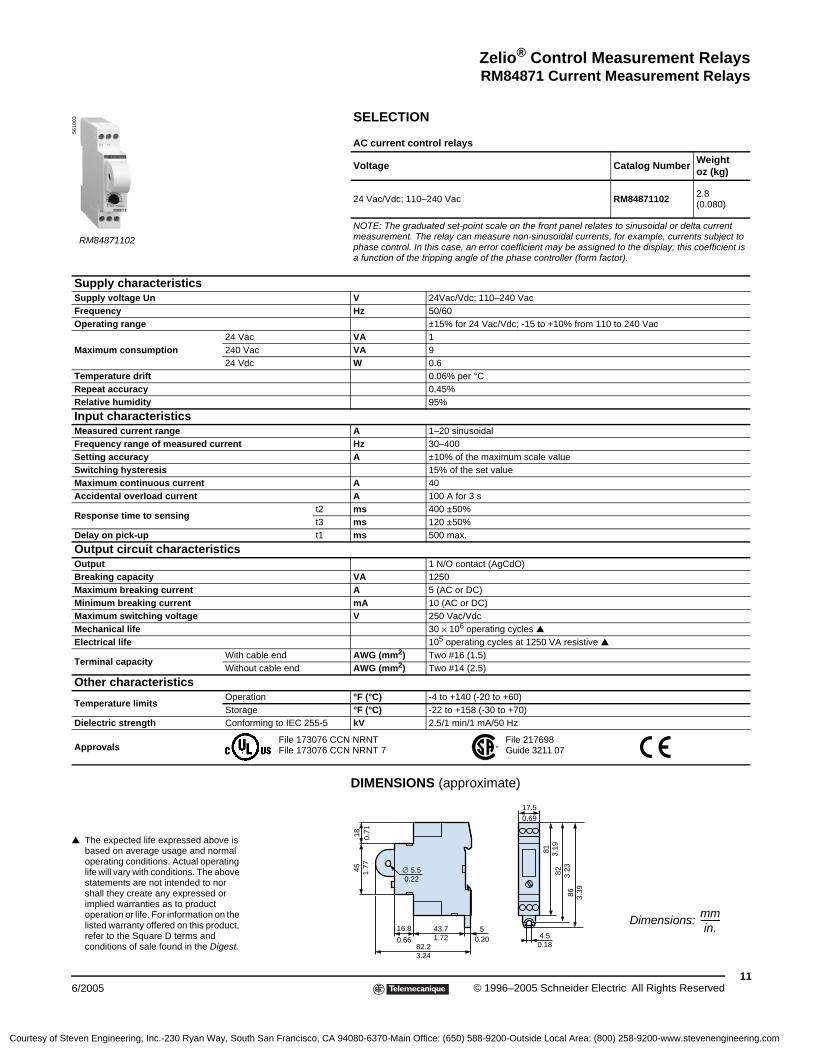
SELECTION
AC current control relays
Voltage Catalog NumberWeight oz (kg)
24 Vac/Vdc; 110–240 Vac RM84871102 2.8(0.080)
NOTE: The graduated set-point scale on the front panel relates to sinusoidal or delta current measurement. The relay can measure non-sinusoidal currents, for example, currents subject to phase control. In this case, an error coefficient may be assigned to the display; this coefficient is a function of the tripping angle of the phase controller (form factor).
Supply characteristicsSupply voltage Un V 24Vac/Vdc; 110–240 VacFrequency Hz 50/60Operating range ±15% for 24 Vac/Vdc; -15 to +10% from 110 to 240 Vac
Maximum consumption24 Vac VA 1240 Vac VA 924 Vdc W 0.6
Temperature drift 0.06% per °CRepeat accuracy 0.45%Relative humidity 95%
Input characteristicsMeasured current range A 1–20 sinusoidalFrequency range of measured current Hz 30–400Setting accuracy A ±10% of the maximum scale valueSwitching hysteresis 15% of the set valueMaximum continuous current A 40Accidental overload current A 100 A for 3 s
Response time to sensingt2 ms 400 ±50% t3 ms 120 ±50%
Delay on pick-up t1 ms 500 max.
Output circuit characteristicsOutput 1 N/O contact (AgCdO)Breaking capacity VA 1250Maximum breaking current A 5 (AC or DC)Minimum breaking current mA 10 (AC or DC)Maximum switching voltage V 250 Vac/VdcMechanical life 30 × 106 operating cycles ▲ Electrical life 105 operating cycles at 1250 VA resistive ▲
Terminal capacityWith cable end AWG (mm2) Two #16 (1.5)Without cable end AWG (mm2) Two #14 (2.5)
Other characteristics
Temperature limitsOperation °F (°C) -4 to +140 (-20 to +60)Storage °F (°C) -22 to +158 (-30 to +70)
Dielectric strength Conforming to IEC 255-5 kV 2.5/1 min/1 mA/50 Hz
Approvals
▲ The expected life expressed above is based on average usage and normal operating conditions. Actual operating life will vary with conditions. The above statements are not intended to nor shall they create any expressed or implied warranties as to product operation or life. For information on the listed warranty offered on this product, refer to the Square D terms and conditions of sale found in the Digest.
DIMENSIONS (approximate)
Dimensions:
RM84871102
5610
03
File 217698Guide 3211 07
File 173076 CCN NRNTFile 173076 CCN NRNT 7
50.20
45 1.77
18 0.71
82.23.24
43.71.72
∅ 5.50.22
16.8
0.66
81 3.19
82 3.23
86 3.39
17.50.69
4.50.18
mmin.
----------
Courtesy of Steven Engineering, Inc.-230 Ryan Way, South San Francisco, CA 94080-6370-Main Office: (650) 588-9200-Outside Local Area: (800) 258-9200-www.stevenengineering.com

12© 1996–2005 Schneider Electric All Rights Reserved 6/2005
Zelio® Control Measurement Relays RM84871 Current Measurement Relays
OPERATING PRINCIPLE
• Space savings, accurate measurement, and optimized functions improve the safety of your electrical installation.
• A DIP switch on the underside of the unit allows you to:
— Select Overcurrent or Undercurrent mode.
— Choose whether to activate the fault memory function, and to set the threshold crossing delay T1 and the inhibit time delay T2.AC/DC mode is detected automatically.
• Accuracy: three products allow you to choose the best product for greater measuring accuracy, provided by a microprocessor.
Control of AC/DC current without memory
When the value of the controlled current (either AC or DC) reaches the threshold displayed on the front panel, the output relay changes state at the end of time delay T1.
It instantly returns to the initial state when the current drops below the hysteresis threshold, or when the power supply is disconnected.
Control of AC/DC current with memory
The output relay changes state at the end of time delay T1 and remains latched in this position. To reset it, the memory function must be reactivated by disconnecting the auxiliary supply.
Overcurrent function
The time delay on energization, T2, prevents current peaks due to motor starting.
The delay on upward crossing of the threshold, T1, provides immunity to transients and other interference, preventing false triggering of the output relay.
Undercurrent function
The time delay on energization, T2, prevents the occurrence of current troughs.
The delay on downward crossing of the threshold, T1, provides immunity to random dips, preventing false triggering of the output relay.
NOTE: In Undercurrent mode, the absolute value of the hysteresis cannot exceed the measurement range maximum.
WIRING
RM8487102p, RM8487103p RM84871044
DIMENSIONS (approximate)
Dimensions:
T2 T2
T2 T2
T1
T1 T1
T1Ove
rcur
rent
func
tion
Und
ercu
rren
t fu
nctio
n
Hys
tere
sis
Meas.input
Thresh-old
U supply
Relay
Withoutfault memory
Meas. input
Thresh-old
Relay
Withfault memory
Hys
tere
sis
E1(+)
E2(+)
M(-)
E3 (+)
U
(+)
(-)
A1
R
11
12 14A2
I
A1 11
14 12 A2
E1 E2 E3
M
A1–A2: Supply
E1(+)
M(-)
U
A1
R
11
12 14A2
I
A1 11
14 12 A2
E1
M
A1–A2: Supply
57 2.24
50.20100
3.94
78.5
3.09
89.7
3.53
99.3
3.91
22.50.89
722.83
4.2
mmin.
----------
Courtesy of Steven Engineering, Inc.-230 Ryan Way, South San Francisco, CA 94080-6370-Main Office: (650) 588-9200-Outside Local Area: (800) 258-9200-www.stevenengineering.com

Zelio® Control Measurement RelaysRM84871 Current Measurement Relays
136/2005 © 1996–2005 Schneider Electric All Rights Reserved
SELECTION Current control relayMeasurement range Supply voltage Catalog Number Weight, oz (kg)
2–500 mA
24 Vac RM84871021 5.3 (0.150)
120 Vac RM84871023 5.3 (0.150)
230 Vac RM84871024 5.3 (0.150)
0.1–10 A
24 Vac RM84871031 5.3 (0.150)
120 Vac RM84871033 5.3 (0.150)
230 Vac RM84871034 5.3 (0.150)
10–100 A with current transformer 230 Vac RM84871044 5.3 (0.150)
AccessoriesDescription Catalog Number Weight, oz (kg)
Current transformer RM26852304 2.3 (0.065)
Auxiliary supply characteristics
Relay typeRM84871021RM84871023RM84871024
RM84871031RM84871033RM84871034
RM84871044
Supply voltage Un V 24, 120, 230 50/60 Hz (galvanic isolation by transformer) 230 50/60 HzOperating range 0.8–1.15 UnAverage consumption VA 3
Output characteristicsOutput relay 1 cadmium-free C/O contactRated current A 8Switching voltage Vac 250Maximum voltage Vac 440Rated breaking capacity VA 2000Minimum breaking current mA 100 at 12 VdcElectrical life AC-12 105 operating cycles at 8 A at 250 Vac (see ▲ on page 11)Mechanical life 2 × 10⁷ operating cycles (see ▲ on page 11)
Time delayOn crossing threshold T1 s 0,1–3 ±10%On energization T2 s 1–20 ±10%
Input characteristics
Measurement rangemA 2–500 – –
A – 0.1–10 10–100 with current transformer
Frequency of the measured signal Hz 40–500Adjustable hysteresis 5–50% of the threshold settingThreshold value 10–100% of the rangeThreshold setting accuracy ±10%
Measurement ranges
Inputs E1-M E2-M E3-M E1-M E2-M E3-M E1-M
SensitivitymA 2–20 10–100 50–500 – – – –A – – – 0.1–1 0.5–5 1–10 10–100
Input resistance kΩ 5 1 0.2 0.1 0.2 0.01 4
Other characteristicsTemperature °F (°C) Operation: -4 to +122 (-20 to +50); Storage: -40 to +178 (-40 to +70)Relative humidity Without condensation 95%Enclosure material Self-extinguishingDegree of protection Conforming to IEC 60529 Enclosure: IP 40D, terminal block: IP 20Connection Stranded wire AWG (mm2) Without cable end: One #12 (4) or two #14 (2.5); with cable end: two #16 (1.5)Tightening torque lb-in (N•m) 8.8 (1)Dielectric strength Conforming to IEC 60255-5 kV 2.5 for 1 minute at 1 mA, 50 HzCreepage distance and clearance
Conforming to IEC 60664-1 kV 4kV/3
Vibration resistance Conforming to IEC 60068-2-6 a = 0.035 mm (0.0014 in.)
Approvals
Immunity to electromagnetic interference (EMC) (application class 2 conforming to EN 61812-1) Electrostatic discharge Conforming to IEC/EN 61000-4-2 Level 3 (6 kV contact, 8 kV air)Electromagnetic fields Conforming to IEC/EN 61000-4-3 Level 3 (10 V/m)Fast transients Conforming to IEC/EN 61000-4-4 Level 3 (2 kV)Shock waves Conforming to IEC/EN 61000-4-5 Level 3 (2 kV)Radio frequencies Conforming to IEC/EN 61000-4-6 Level 3 (10 V rms)Voltage dips and breaks Conforming to IEC/EN 61000-4-11 30% for 10 ms, 60% for 100 ms and 1 s, > 95% for 5 s and 10 msDamped oscillatory wave at 1 MHz Conforming to IEC 61255-22-1 Class III
Radiated and conducted emissions Class B
RM848710••
5614
68
File 217698Guide 3211 07
File 173076 CCN NRNTFile 173076 CCN NRNT 7
Courtesy of Steven Engineering, Inc.-230 Ryan Way, South San Francisco, CA 94080-6370-Main Office: (650) 588-9200-Outside Local Area: (800) 258-9200-www.stevenengineering.com

14© 1996–2005 Schneider Electric All Rights Reserved 6/2005
Zelio® Control Measurement Relays RM4UA Voltage Measurement Relays
FUNCTIONS
These devices detect when voltage exceeds a pre-set threshold on an AC or DC supply. They have a transparent, hinged cover on the front face to prevent accidental alteration of the settings. This cover can be sealed.
Type of Relay Overvoltage ControlOvervoltage or Undervoltage Control ■
Measuring Range
RM4UA0• Yes No 50 mV to 500 V
RM4UA3• Yes Yes 50 mV to 500 V
Applications
• DC motor overspeed control
• Battery monitoring
• Monitoring of AC or DC supplies
• Speed monitoring (with tacho-generator)
PRESENTATION
1 Adjustment of the voltage threshold as a percentage of the setting range maximum value.
2 Hysteresis adjustment from 5–30%. ▲
3 Adjustment of the time delay as a percentage of the setting range maximum value.
4 Switch combining:
— selection of the timing range: 1s, 3s, 10s, 30s, no time delay— selection of overvoltage (>) or undervoltage (<) detection. See table below.
R Yellow LED: Indicates relay state (off for de-energized relay, on for energized relay).
U Green LED: Indicates that supply to the RM4 is present.
Details for Switch 4Switch Position Function Time Delay (t)
< 0 Undervoltage detection No time delay
< 1 Undervoltage detection 0.05 to 1 s
< 3 Undervoltage detection 0.15 to 3 s
< 10 Undervoltage detection 0.5 to 10 s
< 30 Undervoltage detection 1.5 to 30 s
> 0 Overvoltage detection No time delay
> 1 Overvoltage detection 0.05 to 1 s
> 3 Overvoltage detection 0.15 to 3 s
> 10 Overvoltage detection 0.5 to 10 s
> 30 Overvoltage detection 1.5 to 30 s
■ Selection by the switch on the front face.
▲ Value of the voltage difference between energization and de-energization of the output relay (% of the voltage threshold to be measured).
RM4UA01
12
RU
1234
RU
RM4UA0●
Width 0.89 in (22.5mm)
RM4UA3●
Width 0.89 in (22.5mm)
Courtesy of Steven Engineering, Inc.-230 Ryan Way, South San Francisco, CA 94080-6370-Main Office: (650) 588-9200-Outside Local Area: (800) 258-9200-www.stevenengineering.com

Zelio® Control Measurement RelaysRM4UA Voltage Measurement Relays
156/2005 © 1996–2005 Schneider Electric All Rights Reserved
OPERATING PRINCIPLE
The supply voltage is connected to terminals A1–A2. The voltage to be monitored is connected to terminal B1, B2, or B3 and terminal C.
Hysteresis (h) is adjustable from 5–30%: for overvoltage, h = (US1 – US2) / US1; for undervoltage, h = (US2 – US1) / US2. A measurement cycle lasts only 80 ms, allowing rapid detection of voltage changes.
Relays set for overvoltage detection (RM4UA0• or selector on “>” for model RM4UA3•):
When the voltage exceeds threshold setting US1, the output relay is energized (with or without a time delay). When the voltage returns to value US2 below the threshold, the relay is instantaneously de-energized. The value of US2 depends on the hysteresis setting.
Relays set for undervoltage detection (selector on “<”, model RM4UA3• only):
When the voltage falls below threshold setting US1, the output relay is energized (with or without a time delay). When the voltage returns to value US2 above the threshold, the relay is de-energized. The value of US2 depends on the hysteresis setting.
Function Diagrams
Overvoltage Control
Undervoltage Control
NOTE: The measurement ranges can be extended above 500 V by adding a resistor (see page 18). The measurement range on an AC supply can be extended using a voltage transformer whose secondary is connected to the measuring terminals of the corresponding RM4 relay.
t < t
US1US2
15-1815-16
25-2825-26
U supply A1-A2
Voltagemeasured
Relay
t: time delay
Function ">"
t < t
US1US2
15-1815-16
25-2825-26
U supply
Voltage measured
Relay
Function "<"
Courtesy of Steven Engineering, Inc.-230 Ryan Way, South San Francisco, CA 94080-6370-Main Office: (650) 588-9200-Outside Local Area: (800) 258-9200-www.stevenengineering.com

16© 1996–2005 Schneider Electric All Rights Reserved 6/2005
Zelio® Control Measurement Relays RM4UA Voltage Measurement Relays
SPECIFICATIONS
Power Supply Circuit Specifications Type of Relay RM4UA0● RM4UA3●
Rated SupplyVoltage (Un)
Vac 50/60 Hz 24 110–130 220–240 24–240 110–130 220–240 V 380–415 Vdc – – – 24–240 – – –
Average Consumption at Un
VA (Vac) 2 1.9–3.3 2.7–3.5 1.5–3.3 1.9–3.3 2.7–3.4 2.7–3 W (Vdc) – – – 1.2 – – –
Output Relay and Operating SpecificationsType of Relay RM4UA0● RM4UA3●
Number of C/O Contacts, SPDT 1 2
Output Relay StateEnergized when:voltage measured > threshold setting
Energized when:voltage measured > threshold setting (“>” function)voltage measured < threshold setting (“<” function)
Switching Threshold Setting Accuracy As a percentage of the full scale value: ±5%
Switching Threshold Drift≤ 0.06% per °C, depending on the permissible ambient temperature≤ 0.5%, within the supply voltage range (0.85–1.1 Un)
Hysteresis (adjustable) 5–30% of the voltage threshold settingTime Delay Setting Accuracy As a percentage of the full scale value: ±10%Time Delay Drift – ≤ 0.5%, within the supply voltage range (0.85–1.1 Un)
≤ 0.07% per °C, depending on the rated operating temperatureMeasuring Cycle ≤ 80 ms
Measuring Input SpecificationsInternal Input Resistance and Permissible Overload Depending on the Current Measurement RangesType of Relay RM4UA●1 RM4UA●2 RM4UA●3Measurement Range50–60 Hz Vac and Vdc (V)
0.05–0.5
0.3–3
0.5–5
1–10
5–50
10–100
30–300
50–500
Internal Input Resistance Ri (kΩ) 6.6 43 71 23 112 225 668 1111Permissible Continuous Overload (V) 20 60 80 90 150 300 400 550Permissible Non-Repetitive Overload for t ≤ 1 s (V) 25 80 100 100 200 400 500 550
SELECTION
Voltage Measurement Relays: Overvoltage Detection
Time Delay Voltage to be Measured Depending on Connection (Vac or Vdc)
Widthin. (mm)
Output Relay
Supply Voltage50/60 Hz
Catalog Number
Weightlb (kg)
None
0.05–0.5 V
0.3–3 V
0.5–5 V
0.87 (22.5)
1 C/O–SPDT 24 Vac RM4UA01B 0.37 (0.168)110–130 Vac RM4UA01F 0.37 (0.168)
220–240 Vac RM4UA01M 0.37 (0.168)
1–10 V
5–50 V
10–100 V
0.87 (22.5)
1 C/O–SPDT 24 Vac RM4UA02B 0.37 (0.168)110–130 Vac RM4UA02F 0.37 (0.168)
220–240 Vac RM4UA02M 0.37 (0.168)
30–300 V
50–500 V0.87 (22.5)
1 C/O–SPDT 24 Vac RM4UA03B 0.37 (0.168)110–130 Vac RM4UA03F 0.37 (0.168)
220–240 Vac RM4UA03M 0.37 (0.168)
Voltage Measurement Relays: Overvoltage or Undervoltage DetectionAdjustable Time Delay
Voltage to be Measured Depending on Connection (Vac or Vdc)
Widthin. (mm)
Output Relay
Supply Voltage50/60 Hz
Catalog Number
Weight lb (kg)
For additional application data, refer to page 2.
0.05–30 s
0.05–0.5 V
0.3–3 V
0.5–5 V
0.87(22.5)
2 C/O–DPDT 24–240 Vac/Vdc RM4UA31MW 0.37 (0.168)110–130 Vac RM4UA31F 0.37 (0.168)220–240 Vac RM4UA31M 0.37 (0.168)380–415 Vac RM4UA31Q 0.37 (0.168)
1–10 V
5–50 V
10–100 V
1.77 (45)
2 C/O–DPDT 24–240 Vac/Vdc RM4UA32MW 0.37 (0.168)110–130 Vac RM4UA32F 0.37 (0.168)220–240 Vac RM4UA32M 0.37 (0.168)380–415 Vac RM4UA32Q 0.37 (0.168)
30–300 V
50–500 V1.77 (45)
2 C/O–DPDT 24–240 Vac/Vdc RM4UA33MW 0.37 (0.168)110–130 Vac RM4UA33F 0.37 (0.168)220–240 Vac RM4UA33M 0.37 (0.168)380–415 Vac RM4UA33Q 0.37 (0.168)
RM4UA01
Courtesy of Steven Engineering, Inc.-230 Ryan Way, South San Francisco, CA 94080-6370-Main Office: (650) 588-9200-Outside Local Area: (800) 258-9200-www.stevenengineering.com

Zelio® Control Measurement RelaysRM4UA Voltage Measurement Relays
176/2005 © 1996–2005 Schneider Electric All Rights Reserved
DIMENSIONS
WIRING CONNECTIONS
Connection and current values to be measured, depending on type of RM4UA RM4UA●1 A1–A2 supply voltage
B1, B2, B3, C Voltages to be measured (see table to right)
B1–C 0.05–0.5 V RM4UA●2 B1–C 1–10 V RM4UA●3 B2–C 30–300 V
B2–C 0.3–3 V B2–C 5–50 V B3–C 50–500 V
B3–C 0.5–5 V B3–C 10–100 V
Application Diagrams
Example: Overspeed Monitoring (Undervoltage Function)
3.1580
0.8922.5
3.5289.5 3.23
82 Ø 0.164
0.24 6
3.07 783.07 78
0.24 6
Dual Dimensions = in
mm
RM4UA(common side view)
Rail Mounting Direct Mounting
A1 A2 CB1 B3B2
18 16 15
1815
16
B3
B2
B1
A2
A1
C
A1 A2 CB3B2
18 16 15
1815
16
B3
B2
A2
A1
C
A1 A2 CB1 B3B2
2628 2518 16 15
1815
16
B3
2825
26
B2
B1
A2
A1
C
A1 A2 CB3B2
2628 2518 16 15
1815
16
B3
2825
26
B2
A2
A1
C
Terminal BlocksRM4UA01, UA02 RM4UA31, UA32 RM4UA33RM4UA03
Q1
1/L1
2
3/L2
4
5/L3
6 Q41 2Q32 1
Q22 1
151816
252826
RM4UA
M1
M1
A1
A2
B1
C
U
v
Tacho-generator
M1
12
34
56
U1
W1
V1
M1 3 Vac
Courtesy of Steven Engineering, Inc.-230 Ryan Way, South San Francisco, CA 94080-6370-Main Office: (650) 588-9200-Outside Local Area: (800) 258-9200-www.stevenengineering.com

18© 1996–2005 Schneider Electric All Rights Reserved 6/2005
Zelio® Control Measurement Relays RM4UA Voltage Measurement Relays
Example: Measuring Undervoltage
Product selected: RM4UA32FConnection of voltage to be measured: B2–C (5–50 V)
• Undervoltage threshold: 12 Vdc
• Time delay of the output relay (t): 20 s
• Reset voltage threshold: 13.2 V
• Supply voltage: 120 Vac/60 Hz
Adjustments:
• Adjustment of function and timing range, Switch 4 (see page 14 for a detailed list of switch positions):
— Determine whether overvoltage or undervoltage detection is required; in this example undervoltage.
— Determine the timing range and select a time exceeding the time required; in this example, 30 s.
— Position Switch 4 according to the criteria above (in this example, set Switch 4 to < 30).
• Fine adjustment of time delay:
Depending on the maximum range setting displayed on Switch 4 (in this example, 30 s), use the potentiometer, Switch 3, to set the required time delay as a percentage of the value on Switch 4.
In this example, the required time = 20 s. Therefore:
• Set the voltage threshold setting potentiometer, Switch 1, as a percentage of the maximum value of the measuring range selected when wiring.
In this example: wiring is B2–C; the maximum value of the measuring range = 50 V; and the undervoltage threshold = 12 Vdc. Therefore:
Set the hysteresis, Switch 2, as a percentage of the threshold value; in this example:
Extension of the Measuring Range
AC or DC Supply
Simply connect a resistor, Rs, in series with the measuring input, B3 or C.
If the value of Rs is equal to:
The tripping threshold of the relay will be toward the maximum graduation on the threshold setting potentiometer. In general, the power consumed by the resistor does not exceed 0.5 W.
For AC voltages, it is also possible to use a voltage transformer.
Supply by the Measured Voltage
For monitoring mains and power supplies, the RM4UA can be supplied by the voltage to be controlled, if:
• The measurement threshold is within the operating range of the product’s power supply(0.85–1.1 Uc)
• Variations of the voltage to be measured are compatible with the supply and measurement voltage ranges
1234
RU
Switches
t 100×Timing range of Switch 4------------------------------------------------------------------ 20 100×
30---------------------- 66%= = Set the time delay potentiometer,
Switch 3, to 66.
Setting of Switch 1 12 100×50
---------------------- 24%= = Set the voltage threshold setting potentiometer, Switch 1, to 24.
Setting of Switch 2 13.2 12–13.2
------------------------ 9%= = Set the hysteresis, Switch 2, to 9.
RsC
B3
Ri U > 500 V
RM4UA33
Rs Ri UUm--------- 1–⎝ ⎠⎛ ⎞=
where: RiUmU
Internal resistance of input B3–C.Maximum value of threshold setting range.Voltage threshold to be measured.
A1
A2
B2/B3
C
RM4UA
Courtesy of Steven Engineering, Inc.-230 Ryan Way, South San Francisco, CA 94080-6370-Main Office: (650) 588-9200-Outside Local Area: (800) 258-9200-www.stevenengineering.com

Zelio® Control Measurement RelaysRM4UA Voltage Measurement Relays
196/2005 © 1996–2005 Schneider Electric All Rights Reserved
Example: Measuring Overvoltage
Product selected RM4UA32FConnection of voltage to be measured B2–C (5–50 V)
• Overvoltage threshold: 12 Vdc
• Time delay of the output relay (t): 20 s
• Reset voltage threshold: 11 Vdc
• Supply voltage: 120 Vac/60 Hz
Adjustments:
• Adjustment of function and timing range, Switch 4 (See page 14 for a detailed list of switch positions):
— Determine whether overvoltage or undervoltage detection is required; in this example overvoltage.
— Determine the timing range and select a time exceeding the time required; in this example, 30 s.
— Position Switch 4 according to the criteria above; in this example, Switch 4 on > 30.
• Fine adjustment of time delay:
Depending on the maximum range setting displayed on Switch 4 (in this example, 30 s), use the potentiometer, Switch 3, to set the required time delay as a percentage of the value on Switch 4.
In this example, the required time = 20 s. Therefore:
• Set the voltage threshold setting potentiometer, Switch 1, as a percentage of the maximum value of the measuring range selected when wiring.
In this example: wiring is B2–C; the maximum value of the measuring range = 50 V; and the overvoltage threshold = 12 Vdc. Therefore:
Set the hysteresis, Switch 2, as a percentage of the threshold value; in this example:
1234
RU
Switches
t 100×Timing range of Switch 4------------------------------------------------------------------ 20 100×
30---------------------- 66%= = Set the time delay potentiometer,
Switch 3, to 66.
Setting of Switch 1 12 100×50
---------------------- 24%= = Set the voltage threshold setting potentiometer, Switch 1, to 24.
Setting of Switch 2 12 11–12
------------------- 8.3%= = Set the hysteresis, Switch 2, to 8.
Courtesy of Steven Engineering, Inc.-230 Ryan Way, South San Francisco, CA 94080-6370-Main Office: (650) 588-9200-Outside Local Area: (800) 258-9200-www.stevenengineering.com

20© 1996–2005 Schneider Electric All Rights Reserved 6/2005
Zelio® Control Measurement Relays RM84872 Voltage Measurement Relays
OPERATING PRINCIPLE
• Space savings, accurate measurement, and optimized functions improve the safety of your electrical installation.
• Assurance that equipment is working under the correct conditions by checking the supply voltage.
• Using a DIP switch:
— Select Overvoltage or Undervoltage mode.
— Choose whether to activate the fault memory function and the delay on threshold crossing.
• Accuracy: two products for greater measuring accuracy, provided by a microprocessor.
Control of AC/DC voltage without memory
When the value of the controlled voltage (AC or DC) reaches threshold Ue displayed on the front panel, the output relay changes state at the end of time delay T1, which can be set on the front panel to between 0.1 and 3 s.
As soon as the voltage drops below 5–50% of the threshold (hysteresis), the output relay instantly changes state again. Changing the hysteresis on the front panel does not modify the value of the pre-set threshold.
Control of AC/DC voltage with memory
When the value of the controlled voltage (AC or DC) reaches threshold Ue displayed on the front panel, the output relay changes state at the end of time delay T1 (which can be set between 0.1 and 3 s on the front panel) and remains latched in this position.
WIRING
DIMENSIONS (approximate)
Dimensions:
T2 T2
T2 T2
T1
T1 T1
T1
Overloadfunction
Underload function
Hysteresis
Meas.input
Threshold
U supply
Relay
Hysteresis
Without fault memory
Meas.input
Threshold
Relay
With fault memory
E1(+)
E2(+)
M(-)
E3 (+)
U
(+)
(-)
A1
R
11
12 14A2
U
A1 11
14 12 A2
E1 E2 E3
M
A1–A2: Supply
57 2.24
50.20100
3.94
78.5
3.09
89.7
3.53
99.3
3.94
22.572
2.83
4.20.17
mmin.
----------
Courtesy of Steven Engineering, Inc.-230 Ryan Way, South San Francisco, CA 94080-6370-Main Office: (650) 588-9200-Outside Local Area: (800) 258-9200-www.stevenengineering.com

Zelio® Control Measurement RelaysRM84872 Voltage Measurement Relays
216/2005 © 1996–2005 Schneider Electric All Rights Reserved
SELECTION
Measurement range Supply voltage Catalog Number Weight, oz (kg)
0.2–60 V
24 Vac RM84872021 4.2 (0.120)
120 Vac RM84872023 4.2 (0.120)
230 Vac RM84872024 4.2 (0.120)
15–600 V
24 Vac RM84872031 4.2 (0.120)
120 Vac RM84872033 4.2 (0.120)
230 Vac RM84872034 4.2 (0.120)
Auxiliary supply characteristicsRelay type RM8487202p RM8487203p
Supply voltage, Un V 24, 120, 230 50/60 Hz (galvanic isolation by transformer)
Operating range 0.8–1.15 Un
Average consumption VA 3
Output characteristicsOutput relay 1 cadmium-free C/O contact
Rated current A 8
Switching voltage Vac 250
Maximum voltage Vac 440
Rated breaking capacity VA 2000
Minimum breaking current mA 100 at 12 Vdc
Electrical life AC-12 105 operating cycles at 8 A at 250 Vac (see ▲ on page 11)
Mechanical life 2 × 10⁷ operating cycles (see ▲ on page 11)
Time delayOn crossing threshold T1 s 0.1–3 ±10%On crossing threshold T2 s 1–20 ±10%
Delay on pick-up ms 500
Input characteristicsMeasurement range V 0.2–60 15–600
Frequency of the measured signal Hz 40–500
Adjustable hysteresis 5–50% of the threshold setting
Threshold value 10–100% of the range
Threshold setting accuracy ±10%
Measurement rangesInputs E1-M E2-M E3-M E1-M E2-M E3-MSensitivity V 0.2–2 1–10 6–60 15–150 30–300 60–600Input resistance kΩ 2 10 60 100 300 600
Other characteristicsTemperature °F (°C) Operation: -4 to +122 (-20 to +50); Storage: -40 to +158 (-40 to +70)
Relative humidity Without condensation 95%
Enclosure material Self-extinguishing
Degree of protection Conforming to IEC 60529 Enclosure: IP 40D, terminal block: IP 20
ConnectionFlexible cable
Without cable end AWG (mm2) One #12 (4) or two #14 (2.5)With cable end AWG (mm2) Two #16 (1.5)
Tightening torque lb-in (N•m) 8.8 (1)
Dielectric strength Conforming to IEC 60255-5 kV 2.5 kV for 1 min at 1 mA 50 Hz
Creepage distance and clearance
Conforming to IEC 60664-1 kV 4 kV/3
Vibration resistance Conforming to IEC 60068-2-6 a = 0.035 mm (0.0014 in.)
Approvals
Immunity to electromagnetic interference (EMC) (application class 2 conforming to EN 61812-1) Electrostatic discharge Conforming to IEC/EN 61000-4-2 Level 3 (6 kV contact, 8 kV air)
Electromagnetic fields Conforming to IEC/EN 61000-4-3 Level 3 (10 V/m)
Fast transients Conforming to IEC/EN 61000-4-4 Level 3 (2 kV)
Shock waves Conforming to IEC/EN 61000-4-5 Level 3 (2 kV)
Radio frequencies Conforming to IEC/EN 61000-4-6 Level 3 (10 V rms)
Voltage dips and breaks Conforming to IEC/EN 61000-4-11 30% for 10 ms, 60% for 100 ms and 1 s, > 95% for 5 s and 10 ms
Damped oscillatory wave at 1 MHz
Conforming to IEC 61255-22-1 Class III
Radiated and conducted emissions Class B
RM8487203•
5614
67
File 217698Guide 3211 07
File 173076 CCN NRNTFile 173076 CCN NRNT 7
Courtesy of Steven Engineering, Inc.-230 Ryan Way, South San Francisco, CA 94080-6370-Main Office: (650) 588-9200-Outside Local Area: (800) 258-9200-www.stevenengineering.com

22© 1996–2005 Schneider Electric All Rights Reserved 6/2005
Zelio® Control Measurement Relays RM84872 Voltage Measurement Relays
OPERATING PRINCIPLE
• Simple to install, these threshold relays check their own supply voltage level.
• RM48487204•: Select Overvoltage or Undervoltage mode and the memory function via the DIP switches, then set the delay on crossing threshold T1.
• RM48487205•: set the required high and low voltage thresholds and the delay on crossing threshold T1.
Overvoltage–undervoltage control with memory
Two operating modes are available:
• AC/DC voltage control without memory
• AC/DC voltage control with memoryOvervoltage–undervoltage control
Threshold without memoryThreshold without memory
The window threshold relay controls an electrical voltage, which also acts as its power supply (for simplified wiring). When the value of the controlled voltage (AC or DC) fluctuates outside the window, the output relay de-energizes at the end of time delay T1, which can be set between 0.1 and 3 s on the front panel.
It re-energizes when the voltage returns within the window and stays between the upper and lower thresholds, displayed by two potentiometers on the front panel. A fixed hysteresis ensures bounce-free relay switching around the thresholds.
NOTE: When crossing the upper and lower thresholds, time delay T1 provides immunity to transients to prevent false triggering of the output relay.
WIRING DIMENSIONS (approximate)
Dimensions:
T1 T1
T1 T1
Hysteresis
Overloadfunction
Relay
Underloadfunction
Thresh-old
U supply
Relay
Thresh-old
Hysteresis
Withoutfault memory
With fault memory
T1
T1
T2
T2 Hysteresis
Overload function
Meas.input
Underloadfunction
Thresh-old
U supply
Relay
Hysteresis
Withoutfault memory
Meas. input
Thresh-old
Relay
U
(+)
(–)
A1
R
11
12 14A2
U
A1 11
14 12 A2
NC
57 2.24
50.20100
3.94
78.5
3.09
89.7
3.53
99.3
3.91
22.50.89
722.83
4.20.17
mmin.
----------
Courtesy of Steven Engineering, Inc.-230 Ryan Way, South San Francisco, CA 94080-6370-Main Office: (650) 588-9200-Outside Local Area: (800) 258-9200-www.stevenengineering.com

Zelio® Control Measurement RelaysRM84872 Voltage Measurement Relays
236/2005 © 1996–2005 Schneider Electric All Rights Reserved
SELECTION
Type Voltage to be measured Catalog Number Weight, oz (kg)
With memory20–80 Vac/Vdc RM84872046 3.5 (0.100)
65–260 Vac/Vdc RM84872047 3.5 (0.100)
Without memory20–80 Vac/Vdc RM84872056 3.5 (0.100)
65–260 Vac/Vdc RM84872057 3.5 (0.100)
Supply characteristicsRelay type RM8487204• RM8487205•
Supply voltage Un Vac/Vdc 20–80, 65–260
Operating range V 15–150, 50–275
Maximum consumption
260 Vac VA 6.7 6
80 Vac VA 2 2
260 Vdc W 2 2
80 Vdc W 0.8 0.8
Output characteristicsOutput relay 1 cadmium-free C/O contact
Rated current A 8
Switching current Vac 250
Maximum voltage Vac 440
Rated breaking capacity VA 2000
Minimum breaking current mA 100 at 12 Vdc
Electrical life AC-12 105 operating cycles at 8 A at 250 Vac (see ▲ on page 11)
Mechanical life 2 × 10⁷ operating cycles (see ▲ on page 11)
Time delay On crossing threshold T1 s 0.1–3 ±10%
Delay on pick-up ms 500
Input characteristicsRelay type Measures its own supply voltage
Measurement range V 20–80 or 65–260 depending on model
Frequency of the signal measured Hz 50–60 ±1
Hysteresis Adjustable 5–20% Fixed 5%
Threshold setting accuracy ±10%
Repeat accuracy With constant parameters ±0.3%
Temperature drift ±0.5% per °C
Other characteristicsTemperature °F (°C) Operation: -4 to +122 (-20 to +50); Storage: -40 to +158 (-40 to +70)
Relative humidity Without condensation 95%
Enclosure material Self-extinguishing
Degree of protection Conforming to IEC 60529 Enclosure: IP 40D, terminal block: IP 20
ConnectionFlexible cable
Without cable end AWG (mm2) One #12 (4) or two #14 (2.5)
With cable end AWG (mm2) Two #16 (1.5)
Tightening torque lb-in (N•m) 8.8 (1)
Dielectric strength Conforming to IEC 60255-5 kV 2.5 kV for 1 min at 1 mA 50 Hz
Creepage distance and clearance Conforming to IEC 60664-1 kV 4 kV/3
Vibration resistance Conforming to IEC 60068-2-6 a = 0.35 mm (0.014 in.)
Approvals
Immunity to electromagnetic interference (EMC) (application class 2 conforming to EN 61812-1) Electrostatic discharge Conforming to IEC/EN 61000-4-2 Level 3 (6 kV contact, 8 kV air)
Electromagnetic fields Conforming to IEC/EN 61000-4-3 Level 3 (10 V/m)
Fast transients Conforming to IEC/EN 61000-4-4 Level 3 (2 kV)
Shock waves Conforming to IEC/EN 61000-4-5 Level 3 (2 kV)
Radio frequencies Conforming to IEC/EN 61000-4-6 Level 3 (10 V rms)
Voltage dips and breaks Conforming to IEC/EN 61000-4-11 30% for 10 ms, 60% for 100 ms and 1 s, > 95% for 5 s and 10 ms
Damped oscillatory wave at 1 MHz Conforming to IEC 61255-22-1 Class III
Radiated and conducted emissions Class B
RM848720pp
5614
65
File 217698Guide 3211 07
File E173076 CCN NRNTFile E173076 CCN NRNT 7
Courtesy of Steven Engineering, Inc.-230 Ryan Way, South San Francisco, CA 94080-6370-Main Office: (650) 588-9200-Outside Local Area: (800) 258-9200-www.stevenengineering.com

24© 1996–2005 Schneider Electric All Rights Reserved 6/2005
Zelio® Control Measurement Relays RM84871 Current Measurement Relays and RM84872 Voltage Measurement Relays
OPERATING PRINCIPLE
• LCD display showing the actual value and the pre-set value
• Automatic detection for controlling AC or DC signals
• Overload or underload modes selectable
• Threshold and hysteresis separately adjustable
• Memory function in the event of a fault
• Delay on threshold crossing
These devices control an AC or DC electric signal.
The threshold and hysteresis can be adjusted separately via two potentiometers on the front panel of the device. Before powering up the device, the operating mode must be selected using two DIP switches on the underside of the device (with/without memory, over/under value).
The mode is validated when power is applied to terminals A1–A2.
The signal to be monitored is connected between terminal E1, E2, or E3 (depending on the range) and terminal M.
Voltage or current control, without memory
When the value of the controlled signal (AC or DC) reaches the threshold set on the front panel, the output relay opens (fail-safe) at the end of time delay T. It closes immediately when the signal falls below (or rises above, in under-value mode) the threshold minus hysteresis (plus hysteresis, in under-value mode).
Voltage or current control, with memory
When the threshold is reached, the output relay opens at the end of time delay T and remains in that position. The relay is reset by switching off the power supply.
This operating mode enables the detection of over or under values of short duration.
NOTE: The threshold-crossing time delay T, which can be adjusted on the front panel from 0.1 to 3 s, ensures immunity to transients and other interference, to prevent false triggering of the output relay.
In Under Value mode, the absolute value of the hysteresis cannot exceed the maximum of the measurement range.
T T
Threshold
Funct. ROverload
Threshold
Funct. RUnderload
Hysteresis
Hysteresis
U
T
T
Threshold
Funct. ROverload
Threshold
Funct. RUnderload
Hysteresis
Hysteresis
Memory
Memory
Memory
U
Courtesy of Steven Engineering, Inc.-230 Ryan Way, South San Francisco, CA 94080-6370-Main Office: (650) 588-9200-Outside Local Area: (800) 258-9200-www.stevenengineering.com

Zelio® Control Measurement RelaysRM84871 Current Measurement Relays and RM84872 Voltage Measurement Relays
256/2005 © 1996–2005 Schneider Electric All Rights Reserved
Programming: display
Normal mode
In this mode, the device displays the value of the measured signal, its form (Vac or Vdc), the mode selected (OVER or UNDER), the memory function (ON or OFF), and the state of the output relay.
The display indicates a measurement overflow with three dashes on the screen and the flashing symbol OVER.
Parameter entry mode
To modify one of the three parameters (Threshold, Hysteresis or Threshold Delay), set the corresponding potentiometer. The value of the modified parameter automatically appears.
After 2 s, the current value of the measured signal reappears in the display (return to Normal mode).
Parameter display mode
To review the parameters, press the push button (VISU) several times in succession to cycle through the settings. Keep the push button depressed to scroll through the values.
Exception
In Under mode (underload), since the hysteresis always exceeds the threshold, it may exceed the maximum measurement range according to the settings (Threshold + Hysteresis > Max. Threshold). To remedy this problem, when the hysteresis or threshold setting proportions exceed the management capacity, the value of the hysteresis is automatically corrected so that it does not exceed the range maximum. In addition, the UNDER symbol flashes.
Courtesy of Steven Engineering, Inc.-230 Ryan Way, South San Francisco, CA 94080-6370-Main Office: (650) 588-9200-Outside Local Area: (800) 258-9200-www.stevenengineering.com

26© 1996–2005 Schneider Electric All Rights Reserved 6/2005
Zelio® Control Measurement Relays RM84871 Current Measurement Relays and RM84872 Voltage Measurement Relays
SELECTION
Control relay with LCD display: Voltage-CurrentMeasurement Supply voltage Catalog Number Weight, oz (kg)
0.2 –60 V 230 Vac RM84872305 5.6 (0.160)
15 –600 V 230 Vac RM84872310 5.6 (0.160)
2–500 mA 230 Vac RM84871305 5.6 (0.160)
0.1–10 A 230 Vac RM84871310 5.6 (0.160)
Supply characteristicsSupply voltage Vac 230 (50/60 Hz)
Operating range 0.85–1.10 × Un
Maximum power consumption VA 3
Immunity to microbreaks ms 10
Delay on pick-up ms 500
Creepage distance and clearance Conforming to IEC 60664-1 kV 4 kV/3
Output characteristicsRelay type 1 C/O contact, AgCdO, 5 A, 250 V
Minimum current mA 100
Mechanical life 5 to 106 operating cycles (see ▲ on page 11)
Electrical lifeAC-12 VA 1250, 105 operating cycles (see ▲ on page 11)AC-15 Cos ϕ = 0.3, 6000 operating cycles (see ▲ on page 11)DC-13 L/R = 300 ms, 6000 operating cycles (see ▲ on page 11)
Delay on crossing the threshold 0.1–3 s ±10%
LCD display Relay state. Over or Under mode. Memory function. Type of signal (AC or DC).Measurement overflow.
Other characteristicsProtection class Conforming to IEC 529 Terminal block: IP 20, front panel: IP 40, enclosure: IP 50
Enclosure Self-extinguishing
Terminal capacityWith cable end AWG (mm2) Two #16 (1.5)Without cable end AWG (mm2) Two #14 (2.5)
Tightening torque lb-in (N•m) 5.3 (0.6) maximum
Temperature limits °F (°C) Operation: -4 to +140 (-20 to +60); Storage: -22 to +158 (-30 to +70)
Relative humidity 93% without condensation
Dielectric strength Conforming to IEC 255-5 kV 2.5/1 min/1 mA/50 Hz
Approvals
Voltage control relay input characteristicsRelay type RM84872305 RM84872310Input circuits E1-M E2-M E3-M E1-M E2-M E3-M
Measurement ranges V 0.2–2 1–10 6–60 15–150 30–300 60–600
Input resistance kΩ 2 10 60 100 300 650
Maximum continuous voltage at 68 °F (20 °C) V 4 20 120 200 350 650
Peak overload< 1 ms at 68 °F (20 °C) V 50 100 300 – – –< 50 ms at 68 °F (20 °C) kV – – – 2 2 2
Current control relay input characteristicsRelay type RM84871305 RM84871310Input circuits E1-M E2-M E3-M E1-M E2-M E3-M
Measurement ranges 2–20 mA 10–100 mA 50–500 mA 0.1–1 A 0.5–5 A 1–10 A
Input resistance Ω 5 1 0.2 0.1 0.02 0.01
Maximum continuous current at 68 °F (20 °C) 40 mA 200 mA 1 A 2 A 10 A 14 A
Peak overload < 1 ms at 68 °F (20 °C) A 1 5 8 17 20 50
General input characteristicsMaximum line voltage Mains 277 / 480 Vac
Hysteresis Adjustable from 5 to 50% of threshold
Frequency of AC signal measured Hz 40–500
Threshold setting accuracy ±10%
Repeat accuracy ±0.1% with constant parameters
Temperature drift ±0.05% per °C
Voltage drift ≤ 0.5%
RM84872305
5610
60
File E173076 CCN NRNTFile E173076 CCN NRNT 7
File 217698Guide 3211 07
Courtesy of Steven Engineering, Inc.-230 Ryan Way, South San Francisco, CA 94080-6370-Main Office: (650) 588-9200-Outside Local Area: (800) 258-9200-www.stevenengineering.com

Zelio® Control Measurement RelaysRM84871 Current Measurement Relays and RM84872 Voltage Measurement Relays
276/2005 © 1996–2005 Schneider Electric All Rights Reserved
DIMENSIONS (approximate)
RM84871305, RM84871310, RM84872305, RM84872310
Dimensions:
WIRING
RM84871 Current Measurement Relays
Input current to be measured into proper terminal (E1, E2, or E3)
RM84872 Voltage Measurement Relays
Input voltage to be measured into proper terminal (E1, E2, or E3)
662.60
30.123
0.12
A1 11 E3 E2 E1
A2 14 12 M
361.42
45 1.77
501.97
81 3.19
mmin.
----------
U
11
1412M(-)A2
A1E1(+)
E2(+)
E3(+)
+
U ><
a
-a
R
A1 11 E3 E2 E1
A2 14 12 M
Courtesy of Steven Engineering, Inc.-230 Ryan Way, South San Francisco, CA 94080-6370-Main Office: (650) 588-9200-Outside Local Area: (800) 258-9200-www.stevenengineering.com

28© 1996–2005 Schneider Electric All Rights Reserved 6/2005
Zelio® Control Measurement Relays RM4T Three-Phase Monitoring Relays
FUNCTIONS
These devices monitor three-phase supplies, and protect motors and other loads against the faults listed in the table below. They have a transparent, hinged cover on their front face to prevent accidental alteration of the settings. This cover can be sealed.
Fault RM4TG RM4TU RM4TR RM4TA
Phase Reversal Yes Yes Yes Yes
Phase Loss Yes Yes Yes Yes
Undervoltage No Yes No No
Overvoltage and Undervoltage (2 thresholds) No No Yes No
Phase Imbalance No No No Yes
Applications
• Control for connection of moving equipment (site equipment, agricultural equipment, refrigerated trucks)
• Control for protection of personnel and equipment against the consequences of reverse running (lifting, handling, elevators, escalators, etc.)
• Control of sensitive three-phase supplies
• Phase loss protection
• Normal/emergency power supply switching
Features
RM4T
R
1
2
RU
P
A 1
R
34
1
2
RU
<UP
>U
1
2
RU
<UP
>U
RM4TG RM4TU
R Yellow LED: Indicates relay output state.< U Red LED: Undervoltage fault.1 Undervoltage setting potentiometer.
RM4TR31
RM4TR32 RM4TA3
1 Phase imbalance setting potentiometer, from 5–15%2 Potentiometer for setting time delay, 0.1 to 10 s.R Yellow LED: Indicates the relay state.U Green LED: Indicates that the relay power supply is on.A Red LED: Phase imbalance.P Red LED: Phase failure or phase reversal.
RM4TR33
RM4TR34 RM4TA0
R Yellow LED: Indicates relay output state.
1R
<U
1 Time delay function selector:Fault detection delayed (off delay).Fault detection extended (on delay).
2 Potentiometer for setting time delay in s.3 Potentiometer for setting overvoltage.4 Potentiometer for setting undervoltage.R Yellow LED: Indicates the relay state.U Green LED: Indicates that the relay power supply is on.> U Red LED: Overvoltage fault.< U Red LED: Undervoltage fault.P Red LED: Phase failure or phase reversal.
Courtesy of Steven Engineering, Inc.-230 Ryan Way, South San Francisco, CA 94080-6370-Main Office: (650) 588-9200-Outside Local Area: (800) 258-9200-www.stevenengineering.com

Zelio® Control Measurement RelaysRM4T Three-Phase Monitoring Relays
296/2005 © 1996–2005 Schneider Electric All Rights Reserved
OPERATING PRINCIPLE
The supply voltage to be monitored is connected to product terminals L1, L2, and L3.RM4T relays are self-powered by terminals L1, L2, and L3; they require no separate power supply.
• Monitoring rotation direction of phases and detection of complete loss of one or more phases (RM4T all models)
When terminals L1, L2, and L3 are energized, the relay is energized and the yellow LED comes on only if (a) the rotation direction of phases is correct, and (b) all three phases are present. If one or more phases have failed, or if the rotation direction is incorrect, the relay is not energized at switch-on. In normal operation (no fault), the relay is energized; it de-energizes instantaneously (or after the time delay) if one or more phases fails. To prevent detection of the absence or failure of a single phase, a voltage exceeding the detection threshold (≈130 V on RM4TG, undervoltage threshold setting on RM4TU and RM4TR) can be generated back through the control circuit. For this purpose, we recommend using RM4TA relays. The illumination of LED P signals the absence of a phase on RM4TR and RM4TA.
• Overvoltage and undervoltage detection (RM4TR):
In normal operation, the relay is energized and LEDs U and R are lit.If the average of the three voltages between phases fluctuates outside the range to be monitored, the output relay is de-energized.
— Overvoltage: the Red LED “> U” illuminates.
— Undervoltage: the Red LED “< U” illuminates.
When the supply returns toward its rated value, the relay is re-energized according to the hysteresis value (5%), and the corresponding red LED goes out. A switch allows selection of a time delay, adjustable from 0.1 s to 10 s. With the off-delay function , over- or undervoltages have no effect. With the on-delay function , over- or undervoltages delay the re-energization of the relay. Regardless of the switch setting, an over- or undervoltage is detected only if its duration exceeds the measuring cycle time (80 ms).
Function Diagram (RM4TR31, RM4TR32)
Function Diagram (RM4TR33, RM4TR34)
t t
< t
t t t t t
< t
15/18 25/2815/16 25/26
15/18 25/2815/16 25/26
RM4TR31RM4TR32
U L1 L2 L3 0 Volt
1.05 X Setting < USetting < U
Setting > U0.95 X Setting > U
Off-DelayFunction
On-DelayFunction
t: time delay
t t
< t
t t t
< t
15/18 25/2815/16 25/26
15/18 25/2815/16 25/26
242 V 440 V230 V 418 V
208 V 378 V198 V 360 V
RM4TR33RM4TR34
TR33 TR34
UL1 L2 L3
t t
0 Volt
On-DelayFunction
Off-DelayFunction
t: time delay
Courtesy of Steven Engineering, Inc.-230 Ryan Way, South San Francisco, CA 94080-6370-Main Office: (650) 588-9200-Outside Local Area: (800) 258-9200-www.stevenengineering.com

30© 1996–2005 Schneider Electric All Rights Reserved 6/2005
Zelio® Control Measurement Relays RM4T Three-Phase Monitoring Relays
OPERATING PRINCIPLE
• Undervoltage detection only (RM4TU)
In normal operation, the output relay is energized and the yellow LED is lit.
When the average of the three voltages between phases falls below the undervoltage threshold setting, the relay is de-energized after 550 ms and the red LED “< U” illuminates.
Function Diagram
• Detection of phase imbalance (RM4TA)
In normal operation, the output relay is energized and the yellow and green LEDs are lit.
In the event of an imbalance fault, after a time delay set between 0.1 s and 10 s (on RM4TA3 only), the output relay is de-energized, the yellow LED goes out, and red LED A illuminates (RM4TA3• only).
The relay re-energizes when the measured imbalance value drops below 50% of the imbalance setting (hysteresis).
Function Diagram
Example: Imbalance set at 10%, mains supply voltage 400 V
— Relay de-energization threshold:
— Relay re-energization threshold:
NOTE: Distortion in the sine wave of the three-phase supply can cause the RM4T phase supply control relay to malfunction.
t
< t 0 volt
15/18 25/2815/16 25/26
UL1 L2 L3
1.05 x Setting < USetting < U
t: fixed time delay = 550 ms
15-1815-16
25-2825-26
t t
L1
L3 L2
L2
L1 L3
L3
L2 L1
Relay
Imbalance >set threshold Imbalance >
set threshold
t: time delay
400 V 10%– 360 V=
400 V 10%2
------------– 380 V=
Courtesy of Steven Engineering, Inc.-230 Ryan Way, South San Francisco, CA 94080-6370-Main Office: (650) 588-9200-Outside Local Area: (800) 258-9200-www.stevenengineering.com

Zelio® Control Measurement RelaysRM4T Three-Phase Monitoring Relays
316/2005 © 1996–2005 Schneider Electric All Rights Reserved
Output relay and operating characteristics
Relay type RM4 TG RM4 TU RM4 TR RM4 TA
Number of C/O contacts
2 C/O–DPDT 2 C/O–DPDT 2 C/O–DPDT
RM4 TA3• 2 C/O–DPDT
RM4 TA0• 1 C/O–SPDT
Output relay state
Energized during fault-free operation.
De-energized or unable to energize on detection of rotation direction fault or failure of one or more phases.
Energized during fault-free operation.
De-energized on detection of undervoltage or rotation direction fault or failure of one or more phases.
Energized during fault-free operation.
De-energized on detection of overvoltage, undervoltage or rotation direction fault or phase failure.
Energized during fault-free operation.
De-energized on detection of asymmetry fault, phase failure or rotation direction fault.
Switching threshold setting accuracy
As a percentage of the set value – ±3% ±3% ±3%
Switching threshold drift
Depending on the permissible ambient temperature – ≤ 0.06% per °C ≤ 0.06% per °C ≤ 0.06% per °C
Within the measuring range – ≤ 0.5% ≤ 0.5% ≤ 0.5%
Time delay setting accuracy As a percentage of the full-scale value – ±10% ±10% ±10%
Time delay drift
Within the measuring range – ≤ 0.5% ≤ 0.5% ≤ 0.5%
Depending on the rated operational temperature – ≤ 0.07% per °C ≤ 0.07% per °C ≤ 0.07% per °C
Hysteresis Fixed –About 5% of the de-energization threshold
About 5% of the de-energization threshold
About 50% of the asymmetry percentage
Delay on pick-up ms < 650 < 650 < 650 < 650
Measuring cycle ms ≤ 80 ≤ 80 ≤ 80 ≤ 80
Measuring input characteristics
Relay type RM4 TGRM4 T••1RM4 TR33
RM4 T••2RM4 TR34
Nominal voltage V 220–440RM4 T••1: 220–240
RM4 TR33: 220
RM4 T••2: 380–440
RM4 TR34: 400
Maximum operating range V 198–484 160–300 290–484
(1) Minimum voltage required for operation of indicators and of the time delay.
Courtesy of Steven Engineering, Inc.-230 Ryan Way, South San Francisco, CA 94080-6370-Main Office: (650) 588-9200-Outside Local Area: (800) 258-9200-www.stevenengineering.com

32© 1996–2005 Schneider Electric All Rights Reserved 6/2005
Zelio® Control Measurement Relays RM4T Three-Phase Monitoring Relays
SELECTION
Control Relays: Phase Reversal and Presence of Phases
Time Delay Rated Mains Supply Voltage ■
Widthin (mm)
Output RelayCatalog Number
Weight lb (kg)
None220–440 Vac
50/60 Hz0.89 in (22.5 mm)
2 C/O–DPDT
RM4TG20 0.24 (0.110)
Control Relays: Phase Reversal and Presence of Phases + Undervoltage
Time Delay Rated Mains Supply Voltage ■
Control Threshold
Widthin (mm)
Output RelayCatalog Number
Weight lb (kg)
None
220–240 V
50/60 Hz
Undervoltage
160–220 V0.89 in (22.5 mm)
2 C/O–DPDT
RM4TU01 0.24 (0.110)
380–440 V
50/60 Hz
Undervoltage
300–430 V0.89 in (22.5 mm)
2 C/O–DPDT
RM4TU02 0.24 (0.110)
Control Relays: Phase Reversal and Presence of Phases + Overvoltage and Undervoltage Relays with Fixed Voltage Thresholds
Adjustable Time Delay
Rated Mains Supply Voltage ■
Control Threshold
Widthin (mm)
Output RelayCatalog Number
Weight lb (kg)
0.1–10 s
220 V
50/60 Hz
Undervoltage198 V
Overvoltage242 V
0.89 in (22.5 mm)
2 C/O–DPDT
RM4TR33 0.24 (0.110)
400 V
50/60 Hz
Undervoltage360 V
Overvoltage440 V
0.89 in (22.5 mm)
2 C/O–DPDT
RM4TR34 0.24 (0.110)
Relays with Adjustable Voltage Thresholds
Adjustable Time Delay
Rated Mains Supply Voltage ■
Control Threshold
Widthin (mm)
Output RelayCatalog Number
Weight lb (kg)
0.1–10 s
220–240 V
50/60 Hz
Undervoltage160–220 V
Overvoltage220–300 V
0.89 in (22.5 mm)
2 C/O–DPDT
RM4TR31 0.24 (0.110)
380–440V
50/60 Hz
Undervoltage300–430 V
Overvoltage420–480 V
0.89 in (22.5 mm)
2 C/O–DPDT
RM4TR32 0.24 (0.110)
Control Relays: Phase Reversal and Presence of Phases + ImbalanceTime Delay on De-Energization
Rated Mains Supply Voltage ■
Control Threshold
Widthin (mm)
Output RelayCatalog Number
Weightlb (kg)
Fixed
0.5 s
220–240 V
50/60 HzImbalance5–15%
0.89 in (22.5 mm)
1 C/O–SPDTRM4TA01 0.24 (0.110)
380–440 V
50/60 HzImbalance5–15%
0.89 in (22.5 mm)
1 C/O–SPDTRM4TA02 0.24 (0.110)
Adjustable
0.1–10 s
220–240 V
50/60 HzImbalance5–15%
0.89 in (22.5 mm)
2 C/O–DPDT
RM4TA31 0.24 (0.110)
380–440 V
50/60 HzImbalance5–15%
0.89 in (22.5 mm)
2 C/O–DPDT
RM4TA32 0.24 (0.110)
■ Can be used on other supply voltages if the minimum operational voltages, maximum voltage between phases, and compatibility are within the control threshold ranges shown in the specification table on page 31.
For additional application data, refer to page 2.
RM4TG20
RM4TR33
RM4TA01
Courtesy of Steven Engineering, Inc.-230 Ryan Way, South San Francisco, CA 94080-6370-Main Office: (650) 588-9200-Outside Local Area: (800) 258-9200-www.stevenengineering.com

Zelio® Control Measurement RelaysRM4T Three-Phase Monitoring Relays
336/2005 © 1996–2005 Schneider Electric All Rights Reserved
DIMENSIONS (approximate)
WIRING
Application Diagram
Example
3.1580
0.8922.5
3.5289.5 3.23
82Ø 0.16
4
0.24 6
0.24 6
3.07 78
3.07 78
Dual Dimensions = in
mm
Rail Mounting Direct MountingRM4T
L1 L2 L3
28 (24) 26 (22)18 (14)
25 (21)15 (11) 16 (12)
L1 L2 L3
2825 (21)
2616
(24)
(22)18
15 (11)
(14)
(12)
L1 L2 L3
18 15 1628 25 26
1815
16 2825
26
L1 L2 L3
L1 L2 L3
18 15 16
1815
16
L1 L2 L3
Terminal BlocksRM4TG20, TU0● RM4TR3●, TA3● RM4TA0●
L1, L2, L3 Supply to be monitored15(11)-18(14) 1st C/O contact15(11)-16(12) of the output relay25(21)-28(24) 2nd C/O contact25(21)-26(22) of the output relay
L1, L2, L3 Supply to be monitored15–18 1st C/O contact15–16 of the output relay25–28 2nd C/O contact25–26 of the output relay
L1, L2, L3 Supply to be monitored15–18 1st C/O contact15–16 of the output relay
151816
252826
RM4T
M1
M1
1/L1
2
3/L2
4
5/L3
6
Q1
2/T
1
4/T
2
6/T
3
1
Q2
3 5
M1
12
34
56
U1
W1
V1
M1 3
L3L2L1
N
Vac
Select based on load
Suggested Line Fuses for L1, L2, and L3
100 mA, fast blow or standard
Courtesy of Steven Engineering, Inc.-230 Ryan Way, South San Francisco, CA 94080-6370-Main Office: (650) 588-9200-Outside Local Area: (800) 258-9200-www.stevenengineering.com

34© 1996–2005 Schneider Electric All Rights Reserved 6/2005
Zelio® Control Measurement Relays RM84873 Three-Phase Monitoring Relays
OPERATING PRINCIPLE
• Optimized installation and space savings (22.5 mm)
• No adjustment required to monitor phase failure or phase reversal
• Versions with one or two C/O output contacts for selecting the safety level of the installation
• Self-powered for ease of installation; uses the controlled supply for its power supply
These relays monitor for:
• correct sequencing of phases L1, L2, and L3
• a total loss of one of these phases
When the phase sequence is correct, the output relay is energized and the yellow LED is lit.
The relay de-energizes and the LED goes out when one of the following faults occurs:
• an incorrect sequence of phases at terminals L1, L2, and L3
• a total loss of one phase or of all three phases (phase failure detection threshold < 50 Vac)
Timing diagramsRM84873299
RM84873004
WIRING
RM84873299 RM84873004
phase L1
phase L2
phase L3
Relay
phase L1
phase L2
phase L3
Relay
Relay
L1
L1
L2
L2L3
L3
12
11
R
14
3 Ø
L1
L1
L2
L2L3
L3
12
11
R
14
3 Ø
22
21
R
24
L1 L2
12 11 14
L3 L1 L2
12 11 14
22 21 24
L3
Courtesy of Steven Engineering, Inc.-230 Ryan Way, South San Francisco, CA 94080-6370-Main Office: (650) 588-9200-Outside Local Area: (800) 258-9200-www.stevenengineering.com

Zelio® Control Measurement RelaysRM84873 Three-Phase Monitoring Relays
356/2005 © 1996–2005 Schneider Electric All Rights Reserved
SELECTION
Phase control relays
Outputs Catalog NumberWeightoz (kg)
1 C/O RM84873299 3.5
(0.100)
2 C/O RM848730043.5
(0.100)
Input characteristicsSupply voltage Vac 3 @ 230–400 self-powered
Operating range V 200–500
Frequency 50/60 Hz ±1 Hz
Maximum consumption VA 25
Output characteristicsOutput relay Cadmium-free
Rated current A 8
Maximum switching voltage Vac 250 / 440
Rated breaking capacity VA 2000
Minimum breaking current mA 10 / 5 V
Electrical life ▲ AC-12: 105 operating cycles at 8 A / 250 Vac ▲
Mechanical life ▲ 2 × 10⁷ operating cycles ▲
Pick-up delay t1 ms < 200
Drop-out delay t2 ms < 300 in the event of loss of one phase
Other characteristicsCreepage distance and clearance Conforming to IEC 60664-1 kV 4kV/3
Clamping capacityWithout cable end AWG (mm2) Two #14 (2.5)
With cable end AWG (mm2) One #12 (4) or two #16 (1.5)
Tightening torque lb-in (N•m) 8.8 (1); M3 screw/IEC 60947-1
Temperature limitsOperation °F (°C) -4 to +122 (20 to +50)
Storage °F (°C) -22 to +158 (-30 to +70)
Enclosure material Self-extinguishing
Protection class Terminal block IP 20
Enclosure IP 40
Dielectric strength Conforming to IEC 60255-5 2.5 kV/1 min/1 mA/50 Hz
Approvals
DIMENSIONS (approximate)
▲ The expected life expressed above is based on average usage and normal operating conditions. Actual operating life will vary with conditions. The above statements are not intended to nor shall they create any expressed or implied warranties as to product operation or life. For information on the listed warranty offered on this product, refer to the Square D terms and conditions of sale found in the Digest.
Dimensions:
RM84873004
5609
97
File E173076 CCN NRNTFile E173076 CCN NRNT 7
RM84873299 only File 217698Guide 3211 07
78.5
3.09
89.7
3.53
99.3
3.91
22.50.89
4.20.17
57 2.24
50.20
1003.94
722.83 mm
in.----------
Courtesy of Steven Engineering, Inc.-230 Ryan Way, South San Francisco, CA 94080-6370-Main Office: (650) 588-9200-Outside Local Area: (800) 258-9200-www.stevenengineering.com

36© 1996–2005 Schneider Electric All Rights Reserved 6/2005
Zelio® Control Measurement Relays RM84873 Three-Phase Monitoring Relays
OPERATING PRINCIPLE
• Control:
— phase sequence
— phase failure
— voltage drop on one or more phases
• Regeneration rate: 90% of Un
• Power supply: 3 @ 230 Vac and 3 @ 400 Vac
• Dual frequency: 50 and 60 Hz
• Yellow LED: phase presence and relay state
• Relay output: two C/O contacts, 8 A
These relays monitor for:
• correct sequencing of phases L1, L2, and L3
• a regeneration rate equal to 90% (-10% of Un)
When the phase sequence is correct, the output relay is energized and the yellow LED is lit.
The relay de-energizes and the LED goes out when one of the following faults occurs:
• incorrect sequence of phases at terminals L1, L2, and L3
• voltage drop on one or more phases
Timing diagrams
WIRING
RM84873511
RM84873512
T3 T2 T1 T2 T1 T2 T1 T2
100%
100%
100%
0%
0%
0%
11-14/21-24
11-12/21-22
Phase L1
Phase L2
Phase L3
RelayRelay
T3 < 200 ms
L1 L2 L3
L1 L2 L3
R
U V W
22 21 24
12 11 14
L1
L1
L2
L2L3
L3
12
11
R
14
3 Ø
22
21
R
24
Courtesy of Steven Engineering, Inc.-230 Ryan Way, South San Francisco, CA 94080-6370-Main Office: (650) 588-9200-Outside Local Area: (800) 258-9200-www.stevenengineering.com

Zelio® Control Measurement RelaysRM84873 Three-Phase Monitoring Relays
376/2005 © 1996–2005 Schneider Electric All Rights Reserved
SELECTION
Phase control relays
Voltage Catalog NumberWeightoz (kg)
230 Vac RM84873511 4.2 (0.120)
400 Vac RM84873512 4.2 (0.120)
Input characteristicsSupply voltage Vac 3 @ 230 and 3 @ 400 self-poweredOperating range -20 to +15% UnFrequency 50–60 Hz ±1 Hz
Maximum consumption at UnVA 17 at 50 Hz (20 at 60 Hz)VA 23 +15% at 50 Hz (27 at 60 Hz)
Output characteristicsOutput type 2 cadmium-free C/O contactsRated current A 8Maximum switching voltage Vac 250 / 440Rated breaking capacity VA 2000Minimum breaking current mA 100 / 12 VElectrical life ▲ AC-12: 105 operating cycles at 8 A/ 250 Vac ▲ Mechanical life ▲ 2 × 10⁷ operating cycles ▲ Time to onset of fault t2 (dropout) ms < 200Time to disappearance of fault t1 (pickup) ms < 200Clamping capacity Without cable end AWG (mm2) One #12 (4) or two #14 (2.5)
With cable end AWG (mm2) Two #16 (1.5)
Other characteristicsTightening torque lb-in (N•m) 8.8 (1); M3 screw/IEC 60947-1
Temperature limitsOperation °F (°C) -4 to +122 (-20 to +50)Storage °F (°C) -40 to +158 (-40 to +70)
Humidity 95% max. without condensationEnclosure material Self-extinguishing
Protection class Terminal block IP 20Enclosure IP 40
Dielectric strength Conforming to IEC 60255-5 kV 2.5/1 min/1 mA/50 HzCreepage distance and clearance Conforming to IEC 60664-1 kV 4 kV/3Insulation coordination Conforming to IEC 60664-1 Overvoltage category III; degree of pollution 3; 4 kV/3Vibration
Conforming to IEC 60068-2-6
Amplitude mm 0.35 peak
Frequency Hz 10–55
Approvals
DIMENSIONS (approximate)
▲ The expected life expressed above is based on average usage and normal operating conditions. Actual operating life will vary with conditions. The above statements are not intended to nor shall they create any expressed or implied warranties as to product operation or life. For information on the listed warranty offered on this product, refer to the Square D terms and conditions of sale found in the Digest.
Dimensions:
RM84873511
5609
98
File E173076 CCN NRNTFile E173076 CCN NRNT 7
File 217698Guide 3211 07
321.263.5
0.14
953.74
50.20
57 2.24 78 3.07
632.48 22.5
0.89A1 15 Y1
18 16 A2 mmin.
----------
Courtesy of Steven Engineering, Inc.-230 Ryan Way, South San Francisco, CA 94080-6370-Main Office: (650) 588-9200-Outside Local Area: (800) 258-9200-www.stevenengineering.com

38© 1996–2005 Schneider Electric All Rights Reserved 6/2005
Zelio® Control Measurement Relays RM84873 Three-Phase Monitoring Relays
OPERATING PRINCIPLE
• Control:
— phase imbalance (asymmetry)
— phase sequence
— phase failure
— voltage drop on one or more phases
• Asymmetry rate adjustable on the front panel: -5% to -15% of Un
• Power supply: 3 @ 230 Vac and 3 @ 400 Vac
• Dual frequency: 50 and 60 Hz
• Yellow LED: phase presence and relay state
• Relay output: two C/O contacts, 8 A
These relays monitor for:
• correct sequencing of phases L1, L2, and L3
• a regeneration rate of -5% to -15% of Un
When the phase sequence is correct, the output relay is energized and the yellow LED is lit.
The relay de-energizes and the LED goes out when one of the following faults occurs:
• incorrect sequence of phases at terminals L1, L2, and L3
• voltage drop on one or more phases
Timing diagrams
WIRING
RM84873501
RM84873502
T3 T2 T1 T2 T1 T2 T1 T2
100%
100%
100%
0%
0%
0%
11-14/21-24
11-12/21-22
Phase L1
Phase L2
Phase L3
Relay
T3 < 200 ms
L1 L2 L3
L1 L2 L3
R
U V W
22 21 24
12 11 14
L1
L1
L2
L2L3
L3
12
11
R
14
3 Ø
22
21
R
24
Courtesy of Steven Engineering, Inc.-230 Ryan Way, South San Francisco, CA 94080-6370-Main Office: (650) 588-9200-Outside Local Area: (800) 258-9200-www.stevenengineering.com

Zelio® Control Measurement RelaysRM84873 Three-Phase Monitoring Relays
396/2005 © 1996–2005 Schneider Electric All Rights Reserved
SELECTION
Phase asymmetry control relays
Voltage Catalog NumberWeight, oz (kg)
230 Vac RM84873501 4.2 (0.120)
400 Vac RM84873502 4.2 (0.120)
Input characteristicsSupply voltage Vac 3 @ 230 and 3 @ 400 self-powered
Operating range -20 to +15% Un
Frequency 50–60 Hz ±1 Hz
Maximum consumption at UnVA 17 at 50 Hz (20 at 60 Hz)
VA 23 +15% at 50 Hz (27 at 60 Hz)
Output characteristicsOutput type 2 cadmium-free C/O contacts
Rated current A 8
Maximum switching voltage Vac 250 / 440
Rated breaking capacity VA 2000
Minimum breaking current mA 100 / 12 V
Electrical life ▲ AC-12: 105 operating cycles at 8 A/ 250 Vac ▲
Mechanical life ▲ 2 × 10⁷ operating cycles ▲
Time to onset of fault t2 (dropout) ms < 200
Time to disappearance of fault t1 (pickup) ms < 200
Clamping capacityWithout cable end AWG (mm2) One #12 (4) or two #14 (2.5)
With cable end AWG (mm2) Two #16 (1.5)
Other characteristicsTightening torque lb-in (N•m) 8.8 (1); M3 screw/IEC 60947-1
Temperature limits °F (°C) Operation: -4 to +122 (-20 to +50); Storage: -40 to +158 (-40 to +70)
Humidity 95% max. without condensation
Enclosure material Self-extinguishing
Protection class Terminal block IP 20
Enclosure IP 40
Dielectric strength Conforming to IEC 60255-5 kV 2.5/1 min/1 mA/50 Hz
Creepage distance and clearance Conforming to IEC 60664-1 kV 4kV/3
Vibration
Conforming to IEC 60068-2-6
Amplitude mm 0.35 peak
Frequency Hz 10–55
Approvals
DIMENSIONS (approximate)
▲ The expected life expressed above is based on average usage and normal operating conditions. Actual operating life will vary with conditions. The above statements are not intended to nor shall they create any expressed or implied warranties as to product operation or life. For information on the listed warranty offered on this product, refer to the Square D terms and conditions of sale found in the Digest.
Dimensions:
RM84873501
5609
99
File E173076 CCN NRNTFile E173076 CCN NRNT 7
File 217698Guide 3211 07
321.263.5
0.14
953.74
50.20
57 2.24
78 3.07
632.48 22.5
0.89A1 15 Y1
18 16 A2 mmin.
----------
Courtesy of Steven Engineering, Inc.-230 Ryan Way, South San Francisco, CA 94080-6370-Main Office: (650) 588-9200-Outside Local Area: (800) 258-9200-www.stevenengineering.com

40© 1996–2005 Schneider Electric All Rights Reserved 6/2005
Zelio® Control Measurement Relays RM84873 Three-Phase Monitoring Relays
OPERATING PRINCIPLE
• Control:
— phase sequence
— loss of one or more phases
— undervoltage
• Senses its own supply voltage
• Potentiometer for adjusting mains power
• Adjustable time delay in the event of a fault: 0.2–10 s
• Relay output: two C/O contacts, 8 A
• Two LEDs: power on and relay state
On a three-phase supply, this relay simultaneously monitors:
• phase sequence
• loss of a phase, with a maximum regeneration rate of 70% of the voltage indicated by a potentiometer on the front panel
• symmetrical voltage drop on the three phases of less than 20% of the pre-set value
When the three phases are in sequence, the output relay is energized and the yellow LED is lit.
The output relay de-energizes and the LED goes out (after time delay T, adjustable from 0.2–10 s on the front panel) when one of the following faults occurs:
• reversed direction of phase rotation
• absence of one or more phases
• voltage drop
NOTE: Time delay T is not operational during loss of L1 and L2. It operates during loss of L3, phase inversion, or voltage drop. Its purpose is to avoid false triggering of the output relays during transient states, notably during motor starting.
DIMENSIONS (approximate) RM84873010
RM84873012
RM84873015
RM84873016
Dimensions:
WIRING
U (L1)20%
20%
20%
V (L2)
W (L3)
R1/R2
T T T
50.20
773.03
230.91
3.60.14
57 2.24
1003.94
78.5
3.09
89.7
3.53
99.3
3.91
451.77
4.20.17
mmin.
----------
L1
L1
L2
L2L3
L3
12
11
R1
14
3 Ø
22
21
R2
24
L1 L2 L3
12 11 14 242122
Courtesy of Steven Engineering, Inc.-230 Ryan Way, South San Francisco, CA 94080-6370-Main Office: (650) 588-9200-Outside Local Area: (800) 258-9200-www.stevenengineering.com

Zelio® Control Measurement RelaysRM84873 Three-Phase Monitoring Relays
416/2005 © 1996–2005 Schneider Electric All Rights Reserved
SELECTION
Phase sequence and loss of phase control relays
VoltageSetting rangeVac
Catalog NumberWeightoz (kg)
3 @ 230 Vac 180–260 RM84873010 12.3 (0.350)
3 @ 400 Vac 320–460 RM84873012 12.3 (0.350)
3 @ 480 Vac 380–550 RM84873015 12.3 (0.350)
3 @ 575 Vac 460–660 RM84873016 12.3 (0.350)
Technical characteristicsSupply Self-powered, terminals L1–L2
Operating range 0.7–1.2 × Un
Frequency Hz 50/60
Maximum consumption VA 6
Immunity to microbreaks ms 10
Delay on pick-up ms 500
Creepage distance and clearance Conforming to IEC 60664-1 kV 4kV/3
Input characteristicsMeasurement input resistance kΩ 1 at Un
Regeneration rate max. 70% of the threshold setting
Undervoltage detection (symmetrical drop) a 20% of the threshold setting
Threshold setting accuracy ±10%
Output characteristicsOutput type 2 C/O contacts, AgCdO
Breaking capacity 2000 VA (AC), 80 W (DC)
Maximum breaking current AC/DC A 8
Minimum breaking current AC/DC mA 100
Maximum switching voltage Vac/Vdc 250
Electrical life ▲
AC-12 2000 VA, 105 operating cycles ▲
AC-15 Cos ϕ = 0.3, 6000 operating cycles ▲
DC-13 L/R = 300 ms, 6000 operating cycles ▲
Time delay in the event of a fault s 0.2–10 Max.: 10–15
Other characteristicsIndication Power on Green LED
Relay Yellow LED
Enclosure Self-extinguishing
Terminals Without cable end AWG (mm2) Two #14 (2.5)
With cable end AWG (mm2) Two #16 (1.5)
Tightening torque lb-in (N•m) 5.3 (0.6) max.
Temperature limitsOperation °F (°C) -4 to +140 (-20 to +60)
Storage °F (°C) -22 to +158 (-30 to +70)
Relative humidity 93% without condensation
Vibration Amplitude mm 0.35
Frequency Hz 10–55
Insulation resistance Conforming to IEC 60664-1 MΩ > 100 at 500 V
Dielectric strength kV 3 at 1 mA for 1 minute/50 Hz
Approvals
▲ The expected life expressed above is based on average usage and normal operating conditions. Actual operating life will vary with conditions. The above statements are not intended to nor shall they create any expressed or implied warranties as to product operation or life. For information on the listed warranty offered on this product, refer to the Square D terms and conditions of sale found in the Digest.
RM84873010
5610
00
File 217698Guide 3211 07
File E173076 CCN NRNTFile E173076 CCN NRNT 7
Courtesy of Steven Engineering, Inc.-230 Ryan Way, South San Francisco, CA 94080-6370-Main Office: (650) 588-9200-Outside Local Area: (800) 258-9200-www.stevenengineering.com

42© 1996–2005 Schneider Electric All Rights Reserved 6/2005
Zelio® Control Measurement Relays RM84873 Three-Phase Monitoring Relays
OPERATING PRINCIPLE
• Control:
— phase imbalance (asymmetry)
— phase sequence
— disconnection of one or more phases with regenerated voltage equivalent to 95% of Un
• Asymmetry rate adjustable on the front panel: 5–20%
• Three-phase power supply: 3 @ 230 Vac and 3 @ 400 Vac
• Dual frequency: 50 and 60 Hz
• Two LEDs: indicate phase presence and relay state
• Adjustable time delay in the event of a fault: 0.5–10 s
• Relay output:
— one C/O contact, 8 A
— two C/O contacts, 8 A
T1: Delay after a faultT2: Delay on power-downT3: Delay on power-up.
The device is self-powered by two phases. A green LED indicates that the power supply is on.
When the phase sequence is correct and the asymmetry rate is lower than the threshold indicated on the front panel, the output relay is energized and the yellow phase presence LED is lit.
The output relay de-energizes after a delay T1 (adjustable on the front panel) when one of the following faults occurs:
• incorrect phase sequence
• absence of L3
• asymmetry rate higher than the threshold setting: an imbalance representing an increase or decrease in the voltage of two phases compared to the voltage of a different phase
The output relay de-energizes instantaneously in the event of a phase loss on L1 or L2. A hysteresis fixed at about 10% ensures bounce-free relay switching around the threshold.
Since differential measurement is used, the relay does not react to symmetrical increases or decreases in the mains supply.
DIMENSIONS (approximate) WIRINGRM84873300, RM84873301, RM84873310, RM84873311
Dimensions:
RM84873300, RM84873301 RM84873310, RM84873311
L3
L2
T3T3T3 T1 T2 T1T3 T2 T2
100 %
0 %100 %
0 %100 %
0 %100 %
0 %
Phase L1
Phase L2
Phase L3
Asymmetry
Threshold asymmetry rate
Output relay ON(yellow LED) OFF
Hysteresis
R1/R2
50.20
773.03
230.91
3.60.14
57 2.24
1003.94
78.5
3.09 89
.73.
5399
.33.
91
451.77
4.20.17
mmin.
----------
L1
L1
L2
L2
L3L3
12
11
14
3 Ø
L1 L2 L3
12 11 14
L1 L2 L3
12 11 14 242122
L1
L1
L2
L2
L3L3
12
11
14
3 Ø
22
21
24
Courtesy of Steven Engineering, Inc.-230 Ryan Way, South San Francisco, CA 94080-6370-Main Office: (650) 588-9200-Outside Local Area: (800) 258-9200-www.stevenengineering.com
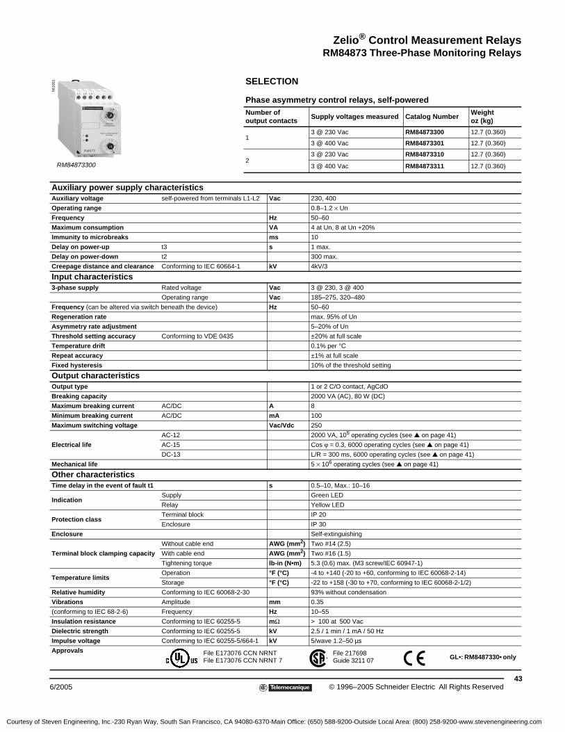
Zelio® Control Measurement RelaysRM84873 Three-Phase Monitoring Relays
436/2005 © 1996–2005 Schneider Electric All Rights Reserved
SELECTION
Phase asymmetry control relays, self-poweredNumber of output contacts
Supply voltages measured Catalog NumberWeightoz (kg)
13 @ 230 Vac RM84873300 12.7 (0.360)
3 @ 400 Vac RM84873301 12.7 (0.360)
23 @ 230 Vac RM84873310 12.7 (0.360)
3 @ 400 Vac RM84873311 12.7 (0.360)
Auxiliary power supply characteristicsAuxiliary voltage self-powered from terminals L1-L2 Vac 230, 400
Operating range 0.8–1.2 × Un
Frequency Hz 50–60
Maximum consumption VA 4 at Un, 8 at Un +20%
Immunity to microbreaks ms 10
Delay on power-up t3 s 1 max.
Delay on power-down t2 300 max.
Creepage distance and clearance Conforming to IEC 60664-1 kV 4kV/3
Input characteristics3-phase supply Rated voltage Vac 3 @ 230, 3 @ 400
Operating range Vac 185–275, 320–480
Frequency (can be altered via switch beneath the device) Hz 50–60
Regeneration rate max. 95% of Un
Asymmetry rate adjustment 5–20% of Un
Threshold setting accuracy Conforming to VDE 0435 ±20% at full scale
Temperature drift 0.1% per °C
Repeat accuracy ±1% at full scale
Fixed hysteresis 10% of the threshold setting
Output characteristicsOutput type 1 or 2 C/O contact, AgCdO
Breaking capacity 2000 VA (AC), 80 W (DC)
Maximum breaking current AC/DC A 8
Minimum breaking current AC/DC mA 100
Maximum switching voltage Vac/Vdc 250
Electrical life
AC-12 2000 VA, 105 operating cycles (see ▲ on page 41)
AC-15 Cos ϕ = 0.3, 6000 operating cycles (see ▲ on page 41)
DC-13 L/R = 300 ms, 6000 operating cycles (see ▲ on page 41)
Mechanical life 5 × 10⁶ operating cycles (see ▲ on page 41)
Other characteristicsTime delay in the event of fault t1 s 0.5–10, Max.: 10–16
IndicationSupply Green LED
Relay Yellow LED
Protection class Terminal block IP 20
Enclosure IP 30
Enclosure Self-extinguishing
Terminal block clamping capacity
Without cable end AWG (mm2) Two #14 (2.5)
With cable end AWG (mm2) Two #16 (1.5)
Tightening torque lb-in (N•m) 5.3 (0.6) max. (M3 screw/IEC 60947-1)
Temperature limitsOperation °F (°C) -4 to +140 (-20 to +60, conforming to IEC 60068-2-14)
Storage °F (°C) -22 to +158 (-30 to +70, conforming to IEC 60068-2-1/2)
Relative humidity Conforming to IEC 60068-2-30 93% without condensation
Vibrations Amplitude mm 0.35
(conforming to IEC 68-2-6) Frequency Hz 10–55
Insulation resistance Conforming to IEC 60255-5 mΩ > 100 at 500 Vac
Dielectric strength Conforming to IEC 60255-5 kV 2.5 / 1 min / 1 mA / 50 Hz
Impulse voltage Conforming to IEC 60255-5/664-1 kV 5/wave 1.2–50 µs
Approvals
RM84873300
5610
01
File E173076 CCN NRNTFile E173076 CCN NRNT 7 GL•: RM8487330• only
File 217698Guide 3211 07
Courtesy of Steven Engineering, Inc.-230 Ryan Way, South San Francisco, CA 94080-6370-Main Office: (650) 588-9200-Outside Local Area: (800) 258-9200-www.stevenengineering.com

44© 1996–2005 Schneider Electric All Rights Reserved 6/2005
Zelio® Control Measurement Relays RM84873 Three-Phase Monitoring Relays
OPERATING PRINCIPLE
• Controls overvoltage and undervoltage on its own power supply (window type)
• RM84873201: phase to phase RM84873211: between phase and neutral
• Minimum and maximum thresholds separately adjustable
• Absence of neutral detected on relay RM84873211
• Delay on crossing the upper or lower threshold, adjustable from 0.1–10 s on the front panel of the device
• Two yellow LEDs: overvoltage and undervoltage
• One green LED: power on
• Two output relays: upper and lower threshold
• Two separate time delays
Tr = about 3 sT1 = adjustable fault delay: 0.1–10 sT2 = adjustable fault delay: 0.1–10 s
The two output contacts are energized when the measured voltages are between the minimum and maximum thresholds, separately adjustable using two potentiometers on the front panel of the device.
When one or more voltages fluctuates outside the window between the two thresholds, the relay corresponding to the fault de-energizes (following a delay adjustable on the front panel). Each relay can have its own individual time delay (0.1 to 10 s).
A hysteresis fixed at 3% ensures bounce-free relay switching when the voltage levels return to a value between the upper and lower thresholds.
The device is not affected by the phase sequence or harmonic distortion.
A green LED indicates that the power supply is on. Two yellow LEDs indicate when the upper and lower thresholds are exceeded: they are lit when the voltages are within the set window.
Catalog Number Lower threshold Upper threshold
RM84873201 340–392 408–460
RM84873211 195–225 235–264
DIMENSIONS (approximate) WIRINGRM84873201, RM84873211 RM84873201 RM84873211
Dimensions:
0
R2
R1T1 T1
Tr
T2
3-phase supplyUpper threshold
Lower threshold
50.20
773.03
230.91
3.60.14
57 2.24
1003.94
78.5
3.09
89.7
3.53
99.3
3.91
451.77
4.20.17
mmin.
----------
L1
L1
L2
L2
L3L3
12
11
14
3 Ø
22
21
24
L1 L2 L3
12 11 14 242122
L1
L1
L2
L2
L3 N
L3N
12
11
14
3 Ø
22
21
24
L1 L2 L3 N
12 11 14 242122
Courtesy of Steven Engineering, Inc.-230 Ryan Way, South San Francisco, CA 94080-6370-Main Office: (650) 588-9200-Outside Local Area: (800) 258-9200-www.stevenengineering.com

Zelio® Control Measurement RelaysRM84873 Three-Phase Monitoring Relays
456/2005 © 1996–2005 Schneider Electric All Rights Reserved
SELECTION
Voltage control relays for 3-phase supply
Power supplies measured Catalog NumberWeightoz (kg)
3 @ 400 Vac RM84873201 10.9 (0.310)
3 @ 400 Vac + neutral RM84873211 10.9 (0.310)
Supply characteristicsSupply voltage Un on terminals L1-L2 Vac 400 ±30% (50/60 Hz)
Maximum power VA 4 at Un8 at Un +20%
Immunity to microbreaks ms 10
Delay on pick-up s About 3
Creepage distance and clearance Conforming to IEC 60664-1 kV 4kV/3
Control circuit characteristicsAdjustment of upper threshold 102–115% of Un
Adjustment of lower threshold 85–98% of Un
Fault delay s 0.1–10 (0 to +50%)
Hysteresis About 3%
Setting accuracy ±10%
Repeat accuracyUpper threshold 0.06%
Lower threshold 0.09%
Temperature drift ±0.05% per °C
Output circuit characteristicsOutput 2 C/O contacts, AgCdO
Breaking capacity 2000 VA (AC), 80 W (DC)
Maximum breaking current AC/DC A 8
Minimum breaking current AC/DC mA 100
Maximum switching voltage Vac or Vdc 250
Mechanical life 30 × 106 operating cycles (see ▲ on page 41)
Electrical life
AC-12 2000 VA, 105 operating cycles (see ▲ on page 41)
AC-15 Cos ϕ = 0.3, 6000 operating cycles (see ▲ on page 41)
DC-13 L/R = 300 ms, 6000 operating cycles (see ▲ on page 41)
Other characteristicsDelay on crossing the threshold s 0.1–10 Max.: 10–15)
Indication
Supply Green LED
Overvoltage relay Yellow LED
Undervoltage relay Yellow LED
Protection class
Conforming to IEC 60529-5
Terminal block IP 20
Enclosure IP 50
Enclosure Self-extinguishing
Terminal capacityWith cable end AWG (mm2) Two #16 (1.5)
Without cable end AWG (mm2) Two #14 (2.5)
Tightening torque Conforming to IEC 60947-1 lb-in (N•m) 5.3 (0.6) max. (M3 screw)
Temperature limitsOperation °F (°C) -4 to +140 (-20 to +60, conforming to IEC 60068-1-14)
Storage °F (°C) -22 to +158 (-30 to +70, conforming to IEC 60068-1-1/2)
Relative humidity Conforming to IEC 60068-2-30 93% without condensation
Vibrations
Conforming to IEC 682-6
Amplitude mm 0.35
Frequency Hz 10–55
Insulation resistance Conforming to IEC 60255-5 MΩ > 10 at 500 Vac
Dielectric strength Conforming to IEC 60255-5 kV > 2.5/1min/1 mA/50 Hz
Impulse voltage Conforming to IEC 60255-5/664-1 kV 5, wave 1.2-50 µs
Approvals
RM84873211
5610
02
File E173076 CCN NRNTFile E173076 CCN NRNT 7
File 217698Guide 3211 07
Courtesy of Steven Engineering, Inc.-230 Ryan Way, South San Francisco, CA 94080-6370-Main Office: (650) 588-9200-Outside Local Area: (800) 258-9200-www.stevenengineering.com

46© 1996–2005 Schneider Electric All Rights Reserved 6/2005
Zelio® Control Measurement Relays RM4UB Single-Phase Monitoring Relays
FUNCTIONS
These devices are designed for monitoring single phase mains and power supplies. They have a transparent, hinged cover on their front face to prevent accidental alteration of the settings. This cover can be sealed.
Applications
• Protecting electronic or electromechanical devices against overvoltage and undervoltage
• Normal/emergency power supply switching
Features
OPERATING PRINCIPLE
The supply voltage to be monitored is connected to product terminals L1, L3. RM4UB relays are self-powered by terminals L1 and L3; they require no separate power supply.
When the voltage fluctuates outside the range to be monitored, the output relay is de-energized.
• Overvoltage: Red LED “> U” illuminates
• Undervoltage: Red LED “< U” illuminates
When the supply returns toward its rated value, the relay is re-energized according to the hysteresis value (5%), and the corresponding red LED goes out. A switch allows selection of an adjustable time delay from 0.1–10 s. With the off-delay function , over- and undervoltages have no effect. With the on-delay function , over- and undervoltages delay the re-energization of the relay. Regardless of the switch setting, an over- or undervoltage is detected only if its duration exceeds the measuring cycle time (80 ms).
Function Diagram
RM4UB
RM4UB1 Overvoltage setting potentiometer2 Undervoltage setting potentiometer3 Time delay function selector
4 Potentiometer for setting time delay (s)R Yellow LED: Indicates relay stateU Green LED: Indicates that supply to the RM4 is present>U Red LED: Overvoltage fault<U Red LED: Undervoltage fault
Fault detection delayed (off delay)
Fault detection extended (on delay)12
3
4
RU
<U>U
t t
< t
t t t t t
< t
15/18 25/2815/16 25/26
15/18 25/2815/16 25/26
RM4UB34RM4UB35
U L1 L3 0 Volt
Setting > U0.95 x Setting > U
1.05 x Setting < USetting < U
FunctionOff Delay
FunctionOn Delay
Courtesy of Steven Engineering, Inc.-230 Ryan Way, South San Francisco, CA 94080-6370-Main Office: (650) 588-9200-Outside Local Area: (800) 258-9200-www.stevenengineering.com

Zelio® Control Measurement RelaysRM4UB Single-Phase Monitoring Relays
476/2005 © 1996–2005 Schneider Electric All Rights Reserved
SPECIFICATIONS
Output Relay and Operational Specifications
Number of C/O (SPDT) Contacts
2 C/O–DPDT
Output Relay State Energized during fault-free operation.
De-energized on detection of an overvoltage or undervoltage fault.
Setting Accuracy of Switching Threshold
As a percentage of the setting value ±3%
Switching Threshold DriftDepending on the permissible ambient temperature ≤ 0.06% per °C
Within the measuring range ≤ 0.5%
Accuracy of Time DelaySetting
As a percentage of the full scale value ±10%
Time Delay DriftWithin the measuring range ≤ 0.5%
Depending on the rated operational temperature ≤ 0.07% per °C
Hysteresis FixedAbout 5% of the
de-energization threshold
Measuring Cycle ≤ 80 ms
Measuring input Specifications
Minimum Operational VoltageRM4UB34: 60 V
RM4UB35: 160 V
Maximum Permissible Voltage Between L1 and L3RM4UB34: 300 V
RM4UB35: 300 V
SELECTION
Relays with Adjustable Thresholds
Adjustable Time Delay
Rated Mains Supply Voltage ■
Control Threshold
Widthin (mm)
Output RelayCatalog Number
Weightlb (kg)
0.1–10 s
100–200 V
50/60 Hz
Undervoltage80–120 V
Overvoltage160–220 V
0.89 in (22.5 mm)
2 C/O
DPDT
RM4UB34 0.24 lb (0.110 kg)
180–270 V
50/60 Hz
Undervoltage160–220 V
Overvoltage220–300 V
0.89 in (22.5 mm)
2 C/O
DPDT
RM4UB35 0.24 lb (0.110 kg)
■ Can be used on other supply voltages if the minimum operational voltages, maximum voltage between phases, and compatibility are within the control threshold ranges shown in the table above.
For additional application data, refer to page 2.
RM4UB
Courtesy of Steven Engineering, Inc.-230 Ryan Way, South San Francisco, CA 94080-6370-Main Office: (650) 588-9200-Outside Local Area: (800) 258-9200-www.stevenengineering.com

48© 1996–2005 Schneider Electric All Rights Reserved 6/2005
Zelio® Control Measurement Relays RM4UB Single-Phase Monitoring Relays
DIMENSIONS (approximate)
WIRING CONNECTIONS
Application Diagram
Example
3.1580
0.8922.5
3.5289.5 3.23
82Ø 0.16
4
0.24 6
0.24 6
3.07 78
3.07 78
Dual Dimensions = in
mm
Rail Mounting Direct MountingRM4UB
L1 L3
18 15 1628 25 26
1815
16 2825
26
L1 L3
Terminal BlocksRM4UB
L1, L2, L3 Supply to be monitored15–18 1st C/O contact15–16 of the output relay25–28 2nd C/O contact25–26 of the output relay
151816
Q2
12
Q2
12
Q11/L1 2
3/L2 4
5/L3 6
Q4
RM4UB
L3L1
To sensitive loads
Courtesy of Steven Engineering, Inc.-230 Ryan Way, South San Francisco, CA 94080-6370-Main Office: (650) 588-9200-Outside Local Area: (800) 258-9200-www.stevenengineering.com

Zelio® Control Measurement RelaysRM4L Liquid Level Relays
496/2005 © 1996–2005 Schneider Electric All Rights Reserved
FUNCTIONS
These devices monitor the levels of conductive liquids. They control the actuation of pumps or valves to regulate levels; they are also suitable for protecting submersible pumps from running empty or tanks from overflowing. They can also control dosing of liquids in mixing processes and protect heating elements in the event of non-immersion. They have a transparent, hinged cover on the front face to prevent accidental alternation of the settings. This cover can be sealed.
• Compatible liquids include, but are not limited to:
— Spring, municipal, industrial, and sea water
— Metallic, acidic, and basic salt solutions
— Liquid fertilizers
— Non-concentrated alcohol (< 40%)
— Liquids in the food processing industry, such as milk, beer, and coffee
• Non-compatible liquids include, but are not limited to:
— Chemically pure water
— Fuels and flammable liquid gases
— Oil and concentrated alcohol (> 40%)
— Ethylene, glycol, paraffin, varnish, and paint
Features
1 Fine adjustment of the time delay (as a percentage of the maximum value of the setting range)2 Fine adjustment of the response sensitivity (as a percentage of the maximum value of the setting range)3 Function selector switch:
empty or fill .4 Switch combining:
— selection of the response sensitivity range
— selection of time delay on energization or de-energization of the relay
R Yellow LED: indicates the relay state (off when de-energized, on when energized)U Green LED: indicates the presence of the relay supply
Details for Switch 3
Switch Position Time Delay Sensitivity
500 On delay High = 500 kΩ range
500 Off delay High = 500 kΩ range
50 On delay Medium = 50 kΩ range
50 Off delay Medium = 50 kΩ range
5 On delay Low = 5 kΩ range
5 Off delay Low = 5 kΩ range
RM4LG01
RM4LA32
23R
U
12
4RU
3
RM4LG01
Width 0.89 in (22.5 mm)
RM4LA32
Width 0.89 in (22.5 mm)
Courtesy of Steven Engineering, Inc.-230 Ryan Way, South San Francisco, CA 94080-6370-Main Office: (650) 588-9200-Outside Local Area: (800) 258-9200-www.stevenengineering.com
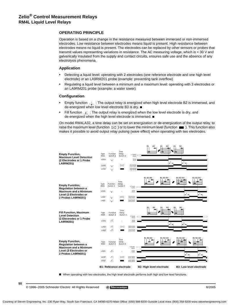
50© 1996–2005 Schneider Electric All Rights Reserved 6/2005
Zelio® Control Measurement Relays RM4L Liquid Level Relays
OPERATING PRINCIPLE
Operation is based on a change in the resistance measured between immersed or non-immersed electrodes. Low resistance between electrodes means liquid is present. High resistance between electrodes means no liquid is present. The electrodes can be replaced by other sensors or probes that transmit values representing variations in resistance. The AC measuring voltage, which is < 30 V and galvanically insulated from the supply and contact circuits, ensures safe use and the absence of any electrolysis phenomena.
Application
• Detecting a liquid level: operating with 2 electrodes (one reference electrode and one high level electrode) or an LA9RM201 probe (example: preventing tank overflow)
• Regulating a liquid level between a minimum and a maximum level: operating with 3 electrodes or an LA9RM201 probe (example: a water tower)
Configuration
• Empty function : The output relay is energized when high level electrode B2 is immersed, and de-energized when low level electrode B3 is dry. ■
• Fill function : The output relay is energized when the low level electrode is dry, and de-energized when the high level electrode is immersed. ■
On model RM4LA32, a time delay can be set on energization or de-energization of the output relay, to raise the maximum level (function ) or to lower the minimum level (function ). This function also makes it possible to avoid output relay pulsing (wave effect) when operating with two electrodes.
Empty Function, Maximum Level Detection (2 Electrodes or 1 Probe LA9RM201)
Empty Function, Regulation between a Maximum and a Minimum Level (3 Electrodes or 2 Probes LA9RM201)
Fill Function, Maximum Level Detection (2 Electrodes or 1 Probe LA9RM201)
Empty Function, Regulation between a Maximum and a Minimum Level (3 Electrodes or 2 Probes LA9RM201)
B1: Reference electrode B2: High level electrode B3: Low level electrode
■ When operating with two electrodes, the high level electrode performs both high and low level functions.
tt
15/18 25/2815/16 25/26
15/18 25/2815/16 25/26
15/18
LA32
LA32
LG01 – 15/16
U SupplyA1/A2
B1 B2B1 B2B1 B2
TypeRM4
FunctionSwitch 3
Time DelaySwitch 4
t t
15/18 25/2815/16 25/26
15/18 25/2815/16 25/26
15/1815/16
B1 B3 B2B1 B3 B2B1 B3 B2B1 B3 B2
LA32
LA32
LG01 –
U SupplyA1/A2
TypeRM4
FunctionSwitch 3
Time DelaySwitch 4
LA32
LA32
LG01 –tt
15/18 25/2815/16 25/26
15/18 25/2815/16 25/26
15/1815/16
B1 B2B1 B2B1 B2
U SupplyA1/A2
TypeRM4
FunctionSwitch 3
Time DelaySwitch 4
tt
15/18 25/2815/16 25/26
15/18 25/2815/16 25/26
15/1815/16
B1 B3 B2B1 B3 B2B1 B3 B2B1 B3 B2
LA32
LA32
LG01 –
U SupplyA1/A2
TypeRM4
FunctionSwitch 3
Time DelaySwitch 4
Courtesy of Steven Engineering, Inc.-230 Ryan Way, South San Francisco, CA 94080-6370-Main Office: (650) 588-9200-Outside Local Area: (800) 258-9200-www.stevenengineering.com

Zelio® Control Measurement RelaysRM4L Liquid Level Relays
516/2005 © 1996–2005 Schneider Electric All Rights Reserved
SPECIFICATIONS
Power Supply Circuit Specifications
Type of Relay50/60 Hz
RM4LG01 RM4LA32
Rated Supply
Voltage (Un)
50/60 HzVac
24 Vac
110–130 Vac
220–240 Vac
380–415 Vac
24–240 Vac
24 Vac
110–130 Vac
220–240 Vac
380–415 Vac
Vdc – – – – 24–240 Vdc – – – –
Average Consumption at Un
Vac 1.9 VA 2.6 VA 2.4 VA 2.9 VA 2.7 VA 3.1 VA 2.7 VA 2.6 VA 3.4 VA
Vdc – – – – 2.4 W – – – –
Output Relay and Operating Specifications
Number of SPDT (C/O) Contacts
1 C/OSPDT
2 C/ODPDT
Output Relay State Switch configurable: empty or fill
Electrode Circuit Specifications ■
Sensitivity Scale 5–100 (adjustable) kΩ 0.25–5 kΩ 2.5–50 kΩ 25–500 kΩ
Maximum AC Electrode Voltage (peak to peak) 24 V 24 V 24 V 24 V
Maximum Current in the Electrodes 1 mA 1 mA 1 mA 1 mA
Maximum Cable Capacity 10 nF 200 nF 25 nF 4 nF
Maximum Cable Length 330 ft (100 m) 3300 ft (1000 m) 330 ft (100 m) 66 ft (20 m)
SELECTION
Liquid Level Control Relays
Time Delay Sensitivity Scale
Widthin (mm)
Output RelayVoltage50/60 Hz
Catalog Number
Weightlb (kg)
None 5–100 kΩ 0.87 in (22.5 mm) 1 C/O–SPDT
24 Vac RM4LG01B 0.36 (0.165)
110–130 Vac RM4LG01F 0.36 (0.165)
220–240 Vac RM4LG01M 0.36 (0.165)
380–415 Vac RM4LG01Q 0.36 (0.165)
Adjustable
0.1–10 s
0.25 -5 kΩ2.5 -50 kΩ25 -500 kΩ
0.87 in (22.5 mm)
2 C/O–DPDT24–240 Vac/ Vdc RM4LA32MW 0.36 (0.165)
24 Vac RM4LA32B 0.36 (0.165)
110–130 Vac RM4LA32F 0.36 (0.165)
220–240 Vac RM4LA32M 0.36 (0.165)
380–415 Vac RM4LA32Q 0.36 (0.165)
Liquid Level Control Probe
Type of Installation Maximum Operating TemperatureCatalog Number
Weightlb (kg)
Suspended by cable 212 °F (100 °C) LA9RM201 0.22 (0.100)
■ The electrodes may also be incorporated in the probes. The probes are normally designed for mounting to a tank using a bracket with a seal (closed tanks) or suspended by their own electrical connecting cable (boreholes, etc.). See page 53 “Setting-up” Probe LA9RM201.
For additional application data, refer to page 2.
For additional probe, refer to page 66.LA9RM201
RM4LA32
RM4LG01
Courtesy of Steven Engineering, Inc.-230 Ryan Way, South San Francisco, CA 94080-6370-Main Office: (650) 588-9200-Outside Local Area: (800) 258-9200-www.stevenengineering.com

52© 1996–2005 Schneider Electric All Rights Reserved 6/2005
Zelio® Control Measurement Relays RM4L Liquid Level Relays
DIMENSIONS
WIRING CONNECTIONS
A1–A2 Supply VoltageB1, B2, B3 Electrodes
(see table below)15–18 1st C/O contact15–16 of the output relay25–28 2nd C/O contact25–26 of the output relay
Electrode and Level Controlled
B1 Reference or tank ground electrode
B2 High Level
B3 Low Level
5.91150
0.63 16
3.1580
0.8922.5
3.5289.5 3.23
82Ø 0.16
4
0.24 6
0.24 6
3.07 78
3.07 78
Dual Dimensions = in
mm
RM4LG01 Rail Mounting Direct Mounting
Probe LA9RM201
B1 B2A1 15
B3
18 16 A2
1815
16
B3
B2
B1
A2
A1
B1 B2A1 15
B325
18 16 A228 26
1815
16
B3
26 2825B
2
B1
A2
A1
RM4LG01 RM4LA32
Courtesy of Steven Engineering, Inc.-230 Ryan Way, South San Francisco, CA 94080-6370-Main Office: (650) 588-9200-Outside Local Area: (800) 258-9200-www.stevenengineering.com

Zelio® Control Measurement RelaysRM4L Liquid Level Relays
536/2005 © 1996–2005 Schneider Electric All Rights Reserved
Setup
1. Select the empty or fill function as appropriate for the application.
2. If necessary, set potentiometer 1 to minimum (time delay).
3. Set potentiometer 2 to minimum. On RM4LA, select the lowest sensitivity range using potentiometer 4 (5 or 5 ).
4. With all the electrodes immersed, turn the sensitivity potentiometer toward maximum until the relay is energized ( function) or de-energized ( function), then exceed the threshold by about 10% to compensate for variation in the supply voltage.
5. If the relay does not energize, do one of the following:
— Use a higher sensitivity scale (selector 4 on RM4LA32)
— Replace relay RM4LG with relay RM4LA32 and start the adjustment procedure again
6. Check that the relay de-energizes ( function) or energizes ( function) as soon as electrodes B3 and B2 are out of the liquid. If the relay does not de-energize, select a lower sensitivity scale.
7. Protect the electrode connection point against corrosion. In areas where thunderstorms are likely, also protect the electrode lines.
NOTE: The high level can be raised from 0.1 –10 s using the adjustable time delay with function . The low level can be lowered using this same time delay with function .
Probe LA9RM201This suspended-type probe is coaxial. In addition to the normal (central) electrode, the stainless steel skirt can also act as the ground (reference) electrode, so no separate reference probe is needed. Controlling one level requires one probe instead of two; controlling two levels requires two probes instead of three. The skirt also acts as a calming chamber to prevent inaccuracy resulting from an agitated surface of the liquid (waves).
Use only a two-conductor connecting cable with common cylindrical PVC sheathing and a maximum diameter of 0.25 in. (6.3 mm).
The maximum operating temperature is 212 °F (100 °C).
Probe LA9RM201 can also be mounted to containers such as cisterns or tanks using a bracket or other suitable mounting device.
23R
U
12
4RU
3
RM4LG01
RM4LA32
2-conductor cable in cylindrical sheath (max. Ø 0.25 in
0.63 mm)
Level Electrode
Reference Electrode(skirt)
B3
B2
B1
A1 B2 B3B1
A2
HighLevel
LowLevel
B1B2
B3B2
B1
RM4LG01
2 Levels 1 Level
Connection ExamplesControl by Electrodes
Control by Probes
Courtesy of Steven Engineering, Inc.-230 Ryan Way, South San Francisco, CA 94080-6370-Main Office: (650) 588-9200-Outside Local Area: (800) 258-9200-www.stevenengineering.com

54© 1996–2005 Schneider Electric All Rights Reserved 6/2005
Zelio® Control Measurement Relays RM84870 Liquid Level Relays
OPERATING PRINCIPLE
• Regulation of two levels: minimum and maximum
• Function to be monitored (filling/UP or emptying/DOWN) selectable using the switch on the front panel of the device
• Probes with AC current flowing through them
• Sensitivity adjustment potentiometer on the front panel of the device
• Sensitivity adjustable from 5–100 kΩ
These devices control maximum and/or minimum levels of conductive liquids (such as tap water, sea water, waste water, chemical solutions, and coffee).
Operation is based on measuring the apparent resistance of the liquid between two submerged probes. When this value falls below the threshold setting on the front panel of the device, the output relay changes state. To avoid electrolytic phenomena, an AC current runs across the probes.
Applications include the food-processing and chemical industries.
Regulation of two levels, minimum/maximum
The output relay changes state when the liquid level reaches the maximum level probe, with the minimum level probe submerged. It returns to its initial state when the minimum level probe is no longer in contact with the liquid.
Filling or emptying control
NOTE: If the voltage break ΔT lasts 1 s or more, then the relay is instantly re-energized if in Up mode or de-energized if in Down mode.
WIRING
Un
TMax. level
Min. level
Output relayDownorUp
Energization of the device
Level being controlled
Emptying functionFilling function
U
11
R
12 14
MaxMinCA1
U
A2
A1 11
14 12 A2
Min.Max.
C
Courtesy of Steven Engineering, Inc.-230 Ryan Way, South San Francisco, CA 94080-6370-Main Office: (650) 588-9200-Outside Local Area: (800) 258-9200-www.stevenengineering.com

Zelio® Control Measurement RelaysRM84870 Liquid Level Relays
556/2005 © 1996–2005 Schneider Electric All Rights Reserved
SELECTION
Filling (Up) and emptying (Down) control relays
Voltage Catalog NumberWeightoz (kg)
24 Vac RM84870001 4.9 (0.140)
120 Vac RM84870003 4.9 (0.140)
230 Vac RM84870004 4.9 (0.140)
NOTE: The probe cable (maximum length 100 m / 328 ft) need not be shielded, but avoid installing it in parallel with the power supply cables.When using shielded cable, connect the shielding to the common.
CharacteristicsSupply voltage Un Vac 24, 120, 230 (50/60 Hz)
Operating range 0.85–1.15 × Un
Maximum power consumption VA 3
Sensitivity adjustment kΩ 5–100
Measurement accuracy(at maximum sensitivity)
0 to +30%
Electrode voltage (maximum) Vac 24 (50/60 Hz)
Electrode current (maximum) mA 1 (50/60 Hz)
Maximum cable capacity nF 10
Response time High level ms 300
Low level ms 500
Output relay (to meet AC-1 requirements, resistive load) 1 C/O contact, AgCdO, 8 A (AC) max.
Galvanic isolation via transformer(4 kV, 8 mm creepage distance)
Class II VDE 0551
Isolation of contacts and electrodes from the supply kVac 2.5
Temperature limits Operation °F (°C) -4 to +140 (-20 to +60)
Storage °F (°C) -22 to +158 (-30 to +70)
Approvals
For probe, refer to page 66.
DIMENSIONS (approximate)
Dimensions:
RM84870001
5610
06
File E173076 CCN NRNTFile E173076 CCN NRNT 7
File 217698Guide 3211 07
78.5
3.09
89.7
3.53
99.3
3.91
22.50.89
4.20.17
57 2.24
50.20
3.50.14
1003.94
722.83
mmin.
----------
Courtesy of Steven Engineering, Inc.-230 Ryan Way, South San Francisco, CA 94080-6370-Main Office: (650) 588-9200-Outside Local Area: (800) 258-9200-www.stevenengineering.com

56© 1996–2005 Schneider Electric All Rights Reserved 6/2005
Zelio® Control Measurement Relays RM84870 Liquid Level Relays
OPERATING PRINCIPLE
• Regulation of two thresholds: minimum or maximum
• Emptying control
• Probes with AC current flowing through them
• Sensitivity adjustment potentiometer on the front panel of the device
• Sensitivity adjustable from:
— 250 kΩ to 5 kΩ (low sensitivity)
— 50 kΩ to 1 MΩ (high sensitivity)
These devices control maximum and/or minimum levels of conductive liquids (such as tap water, sea water, waste water, chemical solutions, and coffee).
Operation is based on measuring the apparent resistance of the liquid between two submerged probes. When this value falls below the threshold setting on the front panel of the device, the output relay changes state. To avoid electrolytic phenomena, an AC current runs across the probes.
Applications include the food-processing and chemical industries.
For values of t1, t2, t3, and t4, refer to page 57.
Regulation of two levels, minimum/maximum
The output relay changes state when the liquid level reaches the maximum level probe, with the minimum level probe submerged. It returns to its initial state when the minimum level probe is no longer in contact with the liquid.
Emptying control
WIRING
Un
t1t2
t3t4
Max. level
Output relay
Min. level
U
11
R
12 14
MaxMinCA1
U
A2
A1 11
14 12 A2
Min.Max.
C
Courtesy of Steven Engineering, Inc.-230 Ryan Way, South San Francisco, CA 94080-6370-Main Office: (650) 588-9200-Outside Local Area: (800) 258-9200-www.stevenengineering.com

Zelio® Control Measurement RelaysRM84870 Liquid Level Relays
576/2005 © 1996–2005 Schneider Electric All Rights Reserved
SELECTION
Emptying control relays (low and high sensitivity)
Voltage Sensitivity Catalog NumberWeightoz (kg)
24 Vac250 Ω to 5 kΩ RM84870121 5.3 (0.150)
50 kΩ to 1 MΩ RM84870131 5.3 (0.150)
NOTE: The probe cable (maximum length 100 m / 328 ft) need not be shielded, but avoid fitting it in parallel with the power supply cables.When using shielded cable, do not exceed the capacities indicated.
CharacteristicsRelay type RE84870121 RE84870131
Supply voltage Vac 24 (50/60 Hz)
Supply range ±15% of Un
-15 to +10% if other products are mounted on the same rail
Maximum power consumption VA 3
Sensitivity adjustment 250 kΩ to 5 kΩ 50 kΩ to 1 MΩ
Measurement accuracy
(at maximum sensitivity)±30% ±30%
Maximum electrode voltage Vac 24 (50/60 Hz) 24 (50/60 Hz)
Maximum electrode current 3 mA (50/60 Hz) 50 µA (50/60 Hz)
Maximum cable capacity nF 100 1
Initialization time t3 ms 650 650
De-energization time t2 s 1 1
Response time t1 (high level) ms 600 600
t4 (low level) 300 ms 2 s
Output relay (to meet AC-1 requirements, resistive load) 1 C/O contact, cadmium-free, 8 A / 250 Vac
Galvanic isolation via transformer(4 kV, 8 mm creepage distance) Class II VDE 0551
Isolation of contacts and electrodes from the supply1 min/1 mA/50 Hz (IEC 60 225-5) kVac 2.5
Creepage distance and clearance Conforming to IEC 60664-1 kV 4kV/2
Ambient air temperatureOperation °F (°C) -4 to +140 (-20 to +60)
Storage °F (°C) -22 to +158 (-30 to +70)
Degree of protection Enclosure IP 50
Terminal block IP 20
Enclosure material Self-extinguishing Pc
Product certifications
For probes, refer to page 66.
DIMENSIONS (approximate)
Dimensions:
RM84870131
5610
07
File E173076 CCN NRNTFile E173076 CCN NRNT 7
File 217698Guide 3211 07
78.5
3.09
89.7
3.53
99.3
3.91
22.5
0.89
4.20.17
57 2.24
50.20
3.50.14
1003.94
722.83
mmin.
----------
Courtesy of Steven Engineering, Inc.-230 Ryan Way, South San Francisco, CA 94080-6370-Main Office: (650) 588-9200-Outside Local Area: (800) 258-9200-www.stevenengineering.com

58© 1996–2005 Schneider Electric All Rights Reserved 6/2005
Zelio® Control Measurement Relays RM84870 Liquid Level Relays
OPERATING PRINCIPLE
• Controlling the levels of conductive liquids
• Regulation of two thresholds: minimum and maximum
• Emptying function
• Plug-in, 8- or 11-pin connector
• Sensitivity adjustable from 5–100 kΩ
These devices control maximum and/or minimum levels of conductive liquids, such as tap water, sea water, waste water, chemical solutions, and coffee.
Operation is based on measuring the apparent resistance of the liquid between two submerged probes. When this value falls below the threshold setting on the front panel of the device, the output relay changes state. To avoid electrolytic phenomena, an AC current runs across the probes.
Applications include the food-processing and chemical industries.
Regulation of two levels, minimum/maximum
The output relay changes state when the liquid level reaches the maximum level probe, with the minimum level probe submerged. It returns to its initial state when the minimum level probe is no longer in contact with the liquid.
Emptying control
WIRING SCHEME
Un
T
Energization of the device
Level being controlled
Emptying function
Max. level
Min. level
Output relay Down
R S T
M P
12
3
45 6
7
8
10
9
11 1
2
3
4 5
67
8
a
bc
c b a
a: Maximumb: Minimumc: Common
8-pin 11-pin
Input
Courtesy of Steven Engineering, Inc.-230 Ryan Way, South San Francisco, CA 94080-6370-Main Office: (650) 588-9200-Outside Local Area: (800) 258-9200-www.stevenengineering.com

Zelio® Control Measurement RelaysRM84870 Liquid Level Relays
596/2005 © 1996–2005 Schneider Electric All Rights Reserved
SELECTION
Liquid level control relays
Number of pins Voltage Catalog NumberWeightoz (kg)
8-pin
24 Vac RM84870301 4.9 (0.140)
120 Vac RM84870303 4.9 (0.140)
230 Vac RM84870304 0.4.9 (0.140)
11-pin
24 Vac RM84870306 4.9 (0.140)
120 Vac RM84870308 4.9 (0.140)
230 Vac RM84870309 4.9 (0.140)
NOTE: The probe cable (maximum length 100 m / 328 ft) need not be shielded, but avoid fitting it in parallel with the power supply cables. When using shielded cable, connect the shielding to the common.
Accessories
Description Catalog NumberWeightoz (kg)
8-pin socketSingle tier
Double tier
8501NR51
8501NR52
1.5 (0.043)
2.1 (0.060)
11-pin socketSingle tier
Double tier
8501NR61
8501NR62
1.8 (0.050)
2.8 (0.078)
Characteristics
Supply voltage Un Vac 24, 120, 230 (50/60 Hz)
Operating range 0.85–1.15 × Un
Maximum power consumption VA 3
Sensitivity adjustment kΩ 5–100
Measurement accuracy(at maximum sensitivity) 0 to +30%
Maximum electrode voltage Vac 24 (50/60 Hz)
Maximum electrode current mA 1 (50/60 Hz)
Maximum cable capacity nF 10
Response timeHigh level ms 300
Low level ms 500
Output relay (to meet AC-1 requirements, resistive load) 1 C/O contact, AgCdO a 8 A max.
Galvanic isolation via transformer(4 kV, 8 mm creepage distance) Class II VDE 0551
Isolation of contacts and electrodes from the supply kVac 2.5
Temperature limitsOperation °F (°C) -4 to +140 (-20 to +60)
Storage °F (°C) -22 to +158 (-30 to +70)
Approvals
For probe, refer to page 66.
DIMENSIONS (approximate)
Dimensions:
RM84870303
5610
08
File E173076 CCN NRNTFile E173076 CCN NRNT 7
File 217698Guide 3211 07
702.76
391.54
50 2.0
160.63
3.50.14
mmin.
----------
Courtesy of Steven Engineering, Inc.-230 Ryan Way, South San Francisco, CA 94080-6370-Main Office: (650) 588-9200-Outside Local Area: (800) 258-9200-www.stevenengineering.com

60© 1996–2005 Schneider Electric All Rights Reserved 6/2005
Zelio® Control Measurement Relays RM84870 Liquid Level Relays
OPERATING PRINCIPLE
• Controlling the levels of conductive liquids
• Combined fill/empty function
• Combined regulation of emptying a well and filling a tank
• Plug-in, 11-pin connector
• LED indicating the output relay state
• Sensitivity adjustable from 5–100 kΩ
Combined fill/empty function
The output relay changes state when the liquid level in the tank reaches the maximum level probe, with the minimum level probe submerged. It returns to its initial state when the minimum level probe is no longer in contact with the liquid.
When the liquid level in the well reaches the minimum level probe, the pump stops.
On energization or after a power supply cutoff, if the maximum level probe in the tank is above the liquid level, reset the device by pressing the push button.
Emptying control
(1) Push button
WIRING SCHEME
Un
(1)(1)(1)Max. levelWellMin. level
Output relay
Max. levelTankMin. level
R S T
M P
12
34
a
bc
5 67
8
109
11
TankWell
Push button
Output
Input
a: maximum.b: minimumc: common
Courtesy of Steven Engineering, Inc.-230 Ryan Way, South San Francisco, CA 94080-6370-Main Office: (650) 588-9200-Outside Local Area: (800) 258-9200-www.stevenengineering.com

Zelio® Control Measurement RelaysRM84870 Liquid Level Relays
616/2005 © 1996–2005 Schneider Electric All Rights Reserved
SELECTION
Liquid level control relays
Number of pins Voltage Catalog NumberWeightoz (kg)
11-pin
24 Vac RM84870401 4.9 (0.140)
120 Vac RM84870403 4.9 (0.140)
230 Vac RM84870404 4.9 (0.140)
Accessories
Description Catalog NumberWeightoz (kg)
11-pin socketSingle tier
Double tier
8501NR61
8501NR62
1.8 (0.050)
2.8 (0.078)
NOTE: The probe cable (maximum length 100 m / 328 ft) need not be shielded, but avoid fitting it in parallel with the power supply cables. When using shielded cable, connect the shielding to the common.
Characteristics
Supply voltage Un Vac 24, 120, 230 (50/60 Hz)
Operating range 0.85–1.15 × Un
Maximum power consumption VA 3
Sensitivity adjustment kΩ 5–100
Measurement accuracy
(at maximum sensitivity)0 to +30%
Maximum electrode voltage Vac 24 (50/60 Hz)
Maximum electrode current mA 1 (50/60 Hz)
Maximum cable capacity nF 10
Response timeHigh level ms 300
Low level ms 500
Output relay (to meet AC-1 requirements, resistive load) 1 C/O contact, AgCdO 8 A max. (AC)
Galvanic isolation via transformer
(4 kV, 8 mm creepage distance)Class II VDE 0551
Isolation of contacts and electrodes from the supply kVac 2.5
Ambient air temperatureOperation °F (°C) -4 to +140 (-20 to +60)
Storage °F (°C) -22 to +158 (-30 to +70)
Product certifications
For probe, refer to page 66.
DIMENSIONS (approximate)
Dimensions:
RM8487040•
5610
09
File E173076 CCN NRNT2File E173076 CCN NRNT 8
File 217698Guide 3211 07
702.76
391.54
50 2.00
160.63
3.50.14
mmin.
----------
Courtesy of Steven Engineering, Inc.-230 Ryan Way, South San Francisco, CA 94080-6370-Main Office: (650) 588-9200-Outside Local Area: (800) 258-9200-www.stevenengineering.com

62© 1996–2005 Schneider Electric All Rights Reserved 6/2005
Zelio® Control Measurement Relays RM84870 Liquid Level Relays
OPERATING PRINCIPLE
• Control and automatic regulation of liquid levels
• Sensitivity adjustable from 5–100 kΩ
• Combined regulation of emptying a well and filling a tank
• LED indicating power on and output relay state
These devices control tank filling at two levels (min. 1, max. 1), with simultaneous control of well or supply tank emptying at two levels (min. 2, max. 2), to protect a pump against running empty.
Operation is based on measuring the apparent resistance of the liquid between two submerged probes. To avoid electrolytic phenomena, an AC current runs across the probes.
NOTE: In certain applications, fine adjustment of sensitivity leads to the detection of undesirable factors, such as the presence of foam or bubbles on the surface of the liquid, or the appearance of leakage impedance between probes (e.g., extended line capacity or humidity).
T1: Delay on pick-upT2: Response time on immersionT3: Response time on emergenceT4: Response time on de-energization
For T values, refer to page 63.
Combined Fill/Empty function
The output relay changes state (de-energizes) when the liquid level in the tank reaches the max. 1 level probe, with the min. 1 level probe submerged. It returns to its initial state (closes) when the min. 1 level probe is no longer in contact with the liquid.
When the liquid level in the well reaches the min. 2 level probe, the pump stops (relay open). This prevents the pump from running empty.
On energization or after a power supply cutoff, if the max. 2 level probe in the tank is above the liquid level, then reset the device by pressing the push button (PB).
WIRING AND APPLICATION SCHEME
Terminals
A1–A211–12–14C–Min. 1–Max. 1C–Min. 2–Max. 2
Supply voltageOutput relay (R)Tank probe inputsWell or supply tank probe inputs
T1 T2 T3 T4
Un
Max. 2
Min. 2
Well
Max. 1
Min. 1
R
PB
Tank
L1
L3L4
C
C
M
R
P
A1 11
A2 12 B.P.14
L2
C
StartStop
Well or supply tank Tank
StartStopMax.
Max.
Min. Min.
Min.1
Min.2
Max.2
Max. 1
Courtesy of Steven Engineering, Inc.-230 Ryan Way, South San Francisco, CA 94080-6370-Main Office: (650) 588-9200-Outside Local Area: (800) 258-9200-www.stevenengineering.com

Zelio® Control Measurement RelaysRM84870 Liquid Level Relays
636/2005 © 1996–2005 Schneider Electric All Rights Reserved
SELECTION
Combined fill and empty function
Voltage Catalog NumberWeightoz (kg)
230 Vac RM84870604 8.8 (0.250)
NOTE: The probe cable (maximum length 100 m / 328 ft) need not be shielded, but avoid installing it close to the power supply cables. To conform to the EMC directive (89/336/EEC), shielded cable must be used, with the shielding connected to the common and to earth.
Supply characteristicsSupply voltage Un Vac 230 (50/60 Hz) electrical isolation via transformer
Operating range 0.85–1.15 Un
Power VA Rated: 3 max. at Un; Maximum: 4 at Un +15%
Immunity to microbreaks ms 10
Delay on pick-up t1 ms 400
Response time on de-energization t4 ms 500
Creepage distance and clearance Conforming to IEC 60664-1 kV 4kV/2
Control characteristicsSensitivity range 5–100 kΩSetting accuracy ±30% at maximum sensitivity
Electrode voltage Vac 15 (50/60 Hz)
Electrode current mA 1
Accuracy ±30% at maximum sensitivity
Response timeOn immersion t2 ms 400
On emergence t3 ms 700
Output circuit characteristicsOutput type 1 C/O contact, AgCdO
Breaking capacity 2000 VA, 80 W
Maximum breaking current AC/DC A 8
Minimum breaking current AC/DC mA 100
Maximum switching voltage Vac/Vdc 250
Mechanical life ▲ 5 × 10⁶ operating cycles ▲
Electrical life ▲
AC-12 2000 VA, 105 operating cycles ▲
AC-15 Cos ϕ = 0.3, 6000 operating cycles ▲
DC-13 L/R = 300 ms, 6000 operating cycles ▲
Other characteristicsEnclosure material Self-extinguishing
Terminal capacityWith cable end AWG (mm2) Two #16 (1.5)
Without cable end AWG (mm2) Two #14 (2.5)
Temperature limitsOperation °F (°C) -4 to +140 (-20 to +60, conforming to IEC 60068-1-14)
Storage °F (°C) -22 to +158 (-30 to +70, conforming to IEC 60068-1-1/2)
Relative humidity 93% without condensation
Approvals
For probes, refer to page 66.
▲ The expected life expressed above is based on average usage and normal operating conditions. Actual operating life will vary with conditions. The above statements are not intended to nor shall they create any expressed or implied warranties as to product operation or life. For information on the listed warranty offered on this product, refer to the Square D terms and conditions of sale found in the Digest.
DIMENSIONS (approximate)
Dimensions:
RM84870604
5610
32
File E173076 CCN NRNTFile E173076 CCN NRNT 7
File 217698Guide 3211 07
577233,5
57
100
78,5
89,7
99,3
45
4,2
mmin.
----------
Courtesy of Steven Engineering, Inc.-230 Ryan Way, South San Francisco, CA 94080-6370-Main Office: (650) 588-9200-Outside Local Area: (800) 258-9200-www.stevenengineering.com

64© 1996–2005 Schneider Electric All Rights Reserved 6/2005
Zelio® Control Measurement Relays RM84870 Liquid Level Relays
OPERATING PRINCIPLE• Control and automatic regulation of liquid levels
• Two sensitivity ranges
• Fill or empty function selectable via DIP switch
• High or low level alarm selectable via DIP switch
• Selectable memory
• LEDs indicating power on, output relay state, and alarm relay state
Control of the level of a conductive liquid at specific points (high and low levels) with alarm when the level is abnormally high or abnormally low.
Operation is based on measuring the apparent resistance of the liquid between submerged probes. When this value is below the threshold setting on the front panel of the device, the output relay R1 and/or the alarm relay R2 change state.
To avoid electrolysis phenomena, an AC current runs across the probes.
NOTE: Alarm relay R2 can be programmed to latch in the de-energized state when a fault occurs by setting a switch on the underside of the device (the switch must be operated with the device switched off). To reset alarm relay R2 once the levels have been re-established, the power supply to the device must be switched off.
Sensitivity adjustment
Set the sensitivity so that the relay changes state when the probes are in contact with the liquid, then returns to its initial position as soon as the probes emerge.
NOTE: In certain applications, fine adjustment of sensitivity leads to the detection of undesirable factors, such as the presence of foam or bubbles on the surface of the liquid, or the appearance of leakage impedance between probes (e.g., extended line capacity or humidity).
Filling control with low level alarm
On energization, probe AI is submerged, relays R1 and R2 change to the energized state, and the pump is on. Filling starts, and the LED for relay R1 is lit. When the liquid reaches the max. level probe, relay R1 changes to the de-energized state, and the pump is off. Filling stops, and the LED for relay R1 goes out. Relay R1 re-energizes when the min. level probe emerges. In the event of a fault (continual drop in level), probe AI is emerged, relay R2 changes to the de-energized state, and the alarm is triggered; the LED for relay R2 comes on. This fault can be memorized.
Filling control with high level alarm
On energization, the level in the tank is low, relays R1 and R2 change to the energized state, and the pump is on. Filling starts, and the LED for relay R1 is lit. When the liquid reaches the max. level probe, relay R1 de-energizes, and the pump is off; filling stops and the relay LED goes out. In the event of a fault, if the level continues to rise and reaches probe AI, relay R2 de-energizes and the alarm is triggered; the LED for relay R2 comes on. This fault can be memorized.
Emptying control with low level alarm
On energization, the min. level, max. level, and AI probes are submerged; relays R1 and R2 change to the energized state; and the pump is on. Emptying starts, and the LED for relay R1 is lit. When the liquid reaches the max. level probe, relay R1 de-energizes and the pump is off; emptying stops, and the LED for relay R1 goes out. In the event of a fault, if the level continues to drop, probe AI emerges, relay R2 de-energizes, and the alarm is triggered; the LED for relay R2 comes on. This fault can be memorized.
T1: Delay on pick-upT2: Response time on
immersionT3: Response time on
emergenceT4: Response time on
energization
Emptying control with high level alarm
On energization, the min. level and max. level probes are submerged and probe AI is above the liquid level; relays R1 and R2 change to the energized state; and the pump is on. Emptying starts, and the LED for relay R1 is lit. When the min. level probe emerges, relay R1 de-energizes, and the pump is off. Emptying stops, and the LED for relay R1 goes out. The relay re-energizes when the max. level probe is submerged. In the event of a fault, if the level continues to rise and reaches probe AI, relay R2 de-energizes and the alarm is triggered; the LED for relay R2 comes on. This fault can be memorized.
ProgrammingThe level controller can be programmed via three switches on the underside of the device:
1 0 1 0Memory OFF ONAlarm Low High
Function Empty Fill
NOTE: The device must be switched off when making Memory, Alarm and Function selections.
T3 T2T1 T2 T4
T3
Memory OFF Memory ON
Un
Max.Min.AI
R1R2
T2
T2
T3T1
T3
Memory OFF Memory ON
UnAIMax.Min.
R1
R2
T3T3 T2T1 T2
Memory OFF Memory ON
Un
Max.Min.AI
R1
R2
T2T1 T3
T3
T4
T2
Memory OFF Memory ON
UnAIMax.Min.
R1
R2
Courtesy of Steven Engineering, Inc.-230 Ryan Way, South San Francisco, CA 94080-6370-Main Office: (650) 588-9200-Outside Local Area: (800) 258-9200-www.stevenengineering.com

Zelio® Control Measurement RelaysRM84870 Liquid Level Relays
656/2005 © 1996–2005 Schneider Electric All Rights Reserved
SELECTION
Liquid level control relays with alarm
Voltage Catalog NumberWeightoz (kg)
230 Vac RM84870504 9.9 (0,280)
NOTE: The probe cable need not be shielded, but avoid installing it close to the power supply cables.To conform to the EMC directive (89/336/EEC), shielded cable must be used, with the shielding connected to the common and to earth.
Supply characteristicsSupply voltage Un Vac 230 (50/60 Hz) galvanic isolation by transformer
Operating range 0.85–1.15 Un
Maximum power VA Rated: 3 at Un; Maximum: 4 at Un +15%
Immunity to microbreaks ms 10
Delay on pick-up t1 s About 2
Response time on de-energization t4t ms 500
Insulation coordination Category III, degree of pollution 2 conforming to IEC 60664-1/VDE 0110: 4 kV/2
Control characteristicsSensitivity range 5–100 kΩSetting accuracy ±30% at maximum sensitivity
Electrode voltage Vac 15 (50/60 Hz)
Electrode current mA 1
Response timeOn immersion t2 ms 400
On emergence t3 ms 700
Output circuit characteristicsOutput type 2 C/O contacts, AgCdO
Breaking capacity 2000 VA, 80 W
Maximum breaking current AC/DC A 8
Minimum breaking current AC/DC mA 100
Maximum switching voltage Vac/Vdc 250
Mechanical life 2 × 10⁶ operating cycles (see ▲ on page 63)
Electrical life
AC-12 2000 VA, 105 operating cycles (see ▲ on page 63)
AC-15 Cos ϕ = 0.3, 6000 operating cycles (see ▲ on page 63)
DC-13 L/R = 300 ms, 6000 operating cycles (see ▲ on page 63)
Other characteristicsEnclosure material Self-extinguishing
Terminal capacityWith cable end AWG (mm2) Two #16 (1.5)
Without cable end AWG (mm2) Two #14 (2.5)
Temperature limitsOperation °F (°C) -4 to +140 (-20 to +60, conforming to IEC 60068-1-14)
Storage °F (°C) -22 to +158 (-30 to +70, conforming to IEC 60068-1-1/2)
Relative humidity 93% without condensation
Approvals
WIRING DIMENSIONS (approximate) Terminal connections
A1–A2 Supply voltage 11–12–14 Output relay (R1)21–22–24 Alarm output relay (R2) C–Min–Max–AI Probe inputsGreen LED Power onYellow LED Output relay stateRed LED Alarm relay state
NOTE: If the reservoir is conductive (metal), it can be used as the reference electrode (C). Dimensions:
RM84870504
5610
33
File E173076 CCN NRNTFile E173076 CCN NRNT 7
File 217698Guide 3211 07
L1
L3L4
C
M
R1 R2
P
A1 11
A2 12 14 22 21 24
L2 50.20
773.03
230.91
3.50.14
57 2.24
1003.94
78.5
3.09 89
.73.
5399
.33.
91
451.77
4.20.17
mmin.
----------
Courtesy of Steven Engineering, Inc.-230 Ryan Way, South San Francisco, CA 94080-6370-Main Office: (650) 588-9200-Outside Local Area: (800) 258-9200-www.stevenengineering.com

66© 1996–2005 Schneider Electric All Rights Reserved 6/2005
Zelio® Control Measurement Relays RM79 Liquid Level Electrode Holders and Probes
SELECTION
Electrode holders
ApplicationNo. of probes
Lengthin. (mm)
Operating temperature°F (°C)
Maximum pressurekg/cm2
Catalog Number
Weightoz (kg)
Recommended for drink-vending machines and where installation space is limited
(Stainless steel)3 39.4 (1000) 176 (80) 2 RM79696044 28.2
(0.800)
Suitable for boilers, pressure vessels and under high temperature conditions (1)
(304 stainless steel)1 39.4 (1000) 392 (200) 25 RM79696014 12.7
(0.360)
Electrodes
Description MaterialCatalog Number
Weightoz (kg)
Protected electrodefor mounting by suspension
Protective shell:PUC (S7)
Electrode: stainless steel
RM79696043 5.3 (0.150)
Electrode for use up to 662 °F (350 °C)and 15 kg/cm2 (2) Stainless steel isolated by ceramic RM79696006 5.3 (0.150)
(1) 3/8" BSP mounting thread with hexagonal head. Use a 24 mm wrench for tightening.(2) 3/8" BSP mounting thread.
Additional probe shown on page 51.
RM79696043
5610
3456
1036
RM79696006
5610
35
Courtesy of Steven Engineering, Inc.-230 Ryan Way, South San Francisco, CA 94080-6370-Main Office: (650) 588-9200-Outside Local Area: (800) 258-9200-www.stevenengineering.com

Zelio® Control Measurement RelaysRM79 Liquid Level Electrode Holders and Probes
676/2005 © 1996–2005 Schneider Electric All Rights Reserved
DIMENSIONS (approximate)
Electrode holders
RM79696044
RM79696014
Probes
RM79696043
RM79696006
Dimensions:
38.51.5232
1.267
0.28
30.12
1 m39.4 in.
140.55 26
1.02∅ 27.51.08
∅ 110.43
120.47
110.43
∅ 6
0.24
100039.4
602.36
602.36
G 3/8A
∅ 2
50.
98
C1
803.15
461.81
291.14
843.31
6.50.26
491.93
20.7
0.82
130.51
9.5
0.37
Acr
oss
flats
1/4
wid
th
5/32
wid
th
3/8 tapered NPT
mmin.
----------
Courtesy of Steven Engineering, Inc.-230 Ryan Way, South San Francisco, CA 94080-6370-Main Office: (650) 588-9200-Outside Local Area: (800) 258-9200-www.stevenengineering.com

68© 1996–2005 Schneider Electric All Rights Reserved 6/2005
Zelio® Control Measurement Relays RM84874 Underspeed Relays
• Detection of motor underspeed, running speed, stopping, or stalling
• Information detected by three-wire or NAMUR sensor, or by contact or voltage
• Time delay adjustable from 100 ms to 10 min in four sub-ranges
• Power-up inhibit time adjustable from 0.3–30 s
• Default time delay adjustable from 0.3–3 s
• LEDs indicating power on and output relay state
Without latching
With latching
OPERATING PRINCIPLE
This control relay is used to resolve problems of underspeed on such devices as conveyor belts and conveyors, where crossing a low speed threshold must trigger an alarm.
Speed information is detected via a sensor (such as a three-wire or NAMUR proximity sensor), a volt-free contact, or the voltage.
On power-up, to allow the controlled process to reach its operating speed, control is inhibited for a time between 0.3 and 30 s, adjustable on the front panel of the control relay. When startup requires an inhibition time exceeding 30 s, external contact S2 must be closed during startup (causing the yellow LED to flash), then opened once nominal speed is reached.
On each cycle of the controlled process, the sensor sends an impulse to the relay. Each of these impulses resets the relay's internal time delay. If the time between two impulses is less than the setting on the relay, then the time delay is reset at each impulse, and the output relay stays closed.
If the speed of the controlled process drops, then the time between two impulses increases. When the time between two impulses exceeds the setting value on the relay, indicating that the controlled process is running at underspeed, the output relay changes state (opens).
The output relay closes again when the speed of the controlled process exceeds the setting value plus the hysteresis (5% of the setting value). If Memory mode is selected, then the relay stays open when an underspeed fault is detected. The output relay can only close again after a manual reset is performed by closing external contact S2.
A yellow LED indicates the state of the relay. A green LED indicates that the power supply is on.
WIRING DIMENSIONS (approximate)
Terminals
AI–A2 Supply voltage11–12–14 Output relay (R)+24 V–E–0 V 3-wire PNP sensorE–0 V Voltage input+8 V 2–Y2 Contact/NAMUR sensor input
HysteresisSpeed displayed
Output relay
Inhibit time delay
0
U
Output relay
Inhibit time delay Inhibit time delay
200 ms min.
0
U
S2
HysteresisSpeed displayed
S1
A1 11
12 14 A2
R
Y1 e
Y2 + 8V2
S2
+ _
+
+~
+_~
_
_
+ 24V - OV
Volt-freecontactNamur
Voltage
3-wire PNP
50.20
773.03
230.91
3.50.14
57 2.24
1003.94
78.5
3.09 89
.73.
5399
.33.
91
451.77
4.20.17
Dimensions: mmin.
----------
Courtesy of Steven Engineering, Inc.-230 Ryan Way, South San Francisco, CA 94080-6370-Main Office: (650) 588-9200-Outside Local Area: (800) 258-9200-www.stevenengineering.com

Zelio® Control Measurement RelaysRM84874 Underspeed Relays
696/2005 © 1996–2005 Schneider Electric All Rights Reserved
SELECTION
Underspeed control relays
Voltage Catalog NumberWeightoz (kg)
230 Vac RM84874304 9.0 (0.255)
Supply characteristicsSupply voltage Un Vac 230 (50/60 Hz) galvanic isolation by transformer
Operating range 0.85–1.15 Un
Maximum power consumption VA 3.5 max. at Un and 5 at Un +15%
Immunity to microbreaks ms 10
Creepage distance and clearance Conforming to IEC 60664-1 kV 4kV/3
Input/control circuit characteristics
Input circuit
3-wire sensor 24 V PNP (50 mA max.)
NAMUR sensor 8.2 V on 1 kΩContact Hard contacts
Voltage input V 30 max.
Input resistance kΩ 16 kΩ except for NAMUR 1
State High V Min. 4.5; max. 30
Low V Min. 0; max. 1
Cut-off frequency Hz 200
Minimum impulse time ms 5
Minimum time between impulses ms 5
Selection of time delay and memory function
Without memory 0.1–1.0 s, 1–10 s, 0.1–1.0 min, 1–10 min8-position switch on front panel
With memory 0.1–1.0 s, 1–10 s, 0.1–1.0 min, 1–10 min
Hysteresis 5% of the threshold setting
Setting accuracy 10% of the full scale value at 77 °F (25 °C)
Repeat accuracy ±0.5% with constant parameters
Temperature drift ±0.05% per °C
Voltage drift ±1% / V
Reset time ms 200 minimum
Reset time for S2 ms 100 minimum
Inhibit time delay s 0.3–30 ±10%
Output circuit characteristicsOutput 1 C/O contact, AgCdO
Breaking capacity 2000 VA, 80 W
Maximum breaking current AC/DC A 8
Minimum breaking current AC/DC mA 100
Maximum switching voltage Vac/Vdc 100
Mechanical life 5 × 10⁶ operating cycles (see ▲ on page 63)
Electrical life
AC-12 2000 VA, 105 operating cycles (see ▲ on page 63)
AC-15 Cos ϕ = 0.3, 6000 operating cycles (see ▲ on page 63)
DC-13 L/R = 300 ms, 6000 operating cycles (see ▲ on page 63)
Other characteristicsEnclosure material Self-extinguishing
Terminal capacityWith cable end AWG (mm2) Two #16 (1.5)
Without cable end AWG (mm2) Two #14 (2.5)
Temperature limitsOperation °F (°C) -4 to +140 (-20 to +60, conforming to IEC 60068-1-14)
Storage °F (°C) -22 to +158 (-30 to +70, conforming to IEC 60068-1-1/2)
Relative humidity 93% without condensation
Approvals
RM84874304
5610
05
File E173076 CCN NRNTFile E173076 CCN NRNT 7
Pending
Courtesy of Steven Engineering, Inc.-230 Ryan Way, South San Francisco, CA 94080-6370-Main Office: (650) 588-9200-Outside Local Area: (800) 258-9200-www.stevenengineering.com

70© 1996–2005 Schneider Electric All Rights Reserved 6/2005
Zelio® Control Measurement Relays RM84873 Motor Load Relays
OPERATING PRINCIPLE
• Self-powered
• Control of motor overload and underload
• Measurement of phase displacement between voltage and current (Cos ϕ)
• Independent adjustment of minimum and maximum thresholds, from 0.1–0.99
• Power-up inhibit time adjustable from 0.5–20 s
• Default time delay adjustable from 0.3–3 s
• Two output relays (one per threshold)
• LEDs indicating power on and output relay state
The control relay is used for motor protection. The variation in the power factor (voltage/current phase displacement or Cos ϕ) is related to the variation in the mechanical load of the motor. The control relay monitors the power factor, and therefore the mechanical load, and checks that it is between two defined and adjustable limits.
A green LED indicates that the power supply is ON.Two yellow LEDs indicate the state of the output relays.
On power-up, the two output relays are closed for the duration of the inhibit time (T2 adjustable from 0.5 to 20 s). When the power factor value is between the two threshold settings, both relays are closed.
When the power factor exceeds the maximum value set by the user, the high threshold relay is de-energized after a time delay T1 (adjustable from 0.3 to 3 s). During this time delay, the green LED flashes (1 Hz). The relay closes again as soon as the measured value drops below the threshold minus the hysteresis.
When the power factor drops below the minimum value set by the user, the low threshold relay is de-energized after a time delay T1 (adjustable from 0.3 to 3 s). During this time delay, the green LED flashes. The relay closes again as soon as the measured value rises above the threshold plus the hysteresis.
If the high threshold value is set below or equal to the low threshold value, the green LED flashes rapidly (2 Hz).
WIRING
T1T2 T1
3-phase supply
Maximum
Minimum
Cos ϕ
R1
R2
L1 L2 L3 E
12 11 14 242122
M
Internalshunt
12
11L1 L2 L3 E
R1 R2
2214 24
21
Three-phase network, I < 10 A ~
3 x 400 V~
Internalshunt
12
11
Load
L1 L2 L3 E
R1 R2
2214 24
21
Single-phase network, 230 V~ TerminalsL1—L2—L3 Network to be monitoredE Current read output11—12—14 Low threshold output relay (R1)21—22—24 High threshold output relay (R2)
230 V~
M
Internalshunt
12
11
External currenttransformer
L1 L2 L3 E
R1 R2
2214 24
21
Three-phase network, I < 10 A ~
3 x 400 V~
Courtesy of Steven Engineering, Inc.-230 Ryan Way, South San Francisco, CA 94080-6370-Main Office: (650) 588-9200-Outside Local Area: (800) 258-9200-www.stevenengineering.com

Zelio® Control Measurement RelaysRM84873 Motor Load Relays
716/2005 © 1996–2005 Schneider Electric All Rights Reserved
SELECTION
Motor load control relays (Cos ϕ)
Power supply/control Catalog NumberWeightoz (kg)
3 @ 230 Vac RM84873400 12.7 (0.360)
3 @ 400 Vac RM84873401 12.7 (0.360)
Supply characteristicsSupply voltage Un Vac 230, 400, self-powered via L1 and L2 Operating range 0.85–1.15 UnPower VA Rated: 2 at Un; Maximum: 3 at Un +15%Immunity to microbreaks ms 10Creepage distance and clearance Conforming to IEC 60664-1 kV 4kV/3
Control input circuit characteristicsThreshold display 0.1–0.99Voltage circuit input resistance kΩ About 2 (Un)Current measurement By internal link via 2 terminalsCurrent range A 0.5–10Input resistance mΩ 20Maximum continuous current A 14 at 68 °F (20 °C)Peak overload A 50 (< 1 s) at 68 °F (20 °C)
Time delaysOn energization (t2) s 0.5–20 ±20% of the full scale valueOn crossing the threshold (t1) s 0.3–3 ±20% of the full scale value
Frequency Hz 50–60
HysteresisCos ϕ ≥ 0.4 10% fixedCos ϕ < 0.4 10% <Hysteresis < 30%
Setting accuracy ±10% of the full scale valueRepeat accuracy ±0.08% with constant parametersTemperature drift ±0.05% per °C
Output circuit characteristicsOutput 2 C/O contacts, AgCdOBreaking capacity 2000 VA, 80 WMaximum breaking current AC/DC A 8Minimum breaking current AC/DC mA 100Maximum switching voltage Vac/Vdc 250Mechanical life ▲ 30 × 106 operating cycles ▲
Electrical life ▲ AC-12 2000 VA, 105 operating cycles ▲ AC-15 Cos ϕ = 0.3, 6000 operating cycles ▲ DC-13 L/R = 300 ms, 6000 operating cycles ▲
Other characteristicsEnclosure material Self-extinguishingTerminal capacity AWG (mm2) With cable end: two #16 (1.5); without cable end: two #14 (2.5)
Temperature limitsOperation °F (°C) -4 to +140 (-20 to +60, conforming to IEC 60068-1-14)Storage °F (°C) -22 to +158 (-30 to +70, conforming to IEC 60068-1-1/2)
Relative humidity 93% without condensation
Approvals
DIMENSIONS
▲ The expected life expressed above is based on average usage and normal operating conditions. Actual operating life will vary with conditions. The above statements are not intended to nor shall they create any expressed or implied warranties as to product operation or life. For information on the listed warranty offered on this product, refer to the Square D terms and conditions of sale found in the Digest.
Dimensions:
RM84873400
5610
04
File E173076 CCN NRNTFile E173076 CCN NRNT 7
Pending
50.20
773.03
230.91
3.50.14
57 2.24
1003.94
78.5
3.09 89
.73.
5399
.33.
91
451.77
4.20.17
mmin.
----------
Courtesy of Steven Engineering, Inc.-230 Ryan Way, South San Francisco, CA 94080-6370-Main Office: (650) 588-9200-Outside Local Area: (800) 258-9200-www.stevenengineering.com
72© 1996–2005 Schneider Electric All Rights Reserved 6/2005
Zelio® Control Measurement Relays
Courtesy of Steven Engineering, Inc.-230 Ryan Way, South San Francisco, CA 94080-6370-Main Office: (650) 588-9200-Outside Local Area: (800) 258-9200-www.stevenengineering.com

Zelio® Control Measurement Relays
736/2005 © 1996–2005 Schneider Electric All Rights Reserved
Courtesy of Steven Engineering, Inc.-230 Ryan Way, South San Francisco, CA 94080-6370-Main Office: (650) 588-9200-Outside Local Area: (800) 258-9200-www.stevenengineering.com

Zelio® Control Measurement RelaysIndex of Catalog Numbers
74© 1996–2005 Schneider Electric All Rights Reserved 6/2005
INDEX OF CATALOG NUMBERS
8501NR51 . . . . . . . . . . . . . . . . . . . . .598501NR52 . . . . . . . . . . . . . . . . . . . . .598501NR61 . . . . . . . . . . . . . . . . . .59, 618501NR62 . . . . . . . . . . . . . . . . . .59, 61LA9RM201 . . . . . . . . . . . . . . . . . . . . .51RM26852304 . . . . . . . . . . . . . . . . . . .13RM4JA01B. . . . . . . . . . . . . . . . . . . . . .6RM4JA01F . . . . . . . . . . . . . . . . . . . . . .6RM4JA01M . . . . . . . . . . . . . . . . . . . . .6RM4JA31F . . . . . . . . . . . . . . . . . . . . . .6RM4JA31M . . . . . . . . . . . . . . . . . . . . .6RM4JA31MW. . . . . . . . . . . . . . . . . . . .6RM4JA31Q . . . . . . . . . . . . . . . . . . . . .6RM4JA32F . . . . . . . . . . . . . . . . . . . . . .6RM4JA32M . . . . . . . . . . . . . . . . . . . . .6RM4JA32MW. . . . . . . . . . . . . . . . . . . .6RM4JA32Q . . . . . . . . . . . . . . . . . . . . .6RM4LA32B. . . . . . . . . . . . . . . . . . . . .51RM4LA32F. . . . . . . . . . . . . . . . . . . . .51RM4LA32M . . . . . . . . . . . . . . . . . . . .51RM4LA32MW. . . . . . . . . . . . . . . . . . .51RM4LA32Q . . . . . . . . . . . . . . . . . . . .51RM4LG01B . . . . . . . . . . . . . . . . . . . .51RM4LG01F . . . . . . . . . . . . . . . . . . . .51RM4LG01M . . . . . . . . . . . . . . . . . . . .51RM4LG01Q . . . . . . . . . . . . . . . . . . . .51RM4TA01. . . . . . . . . . . . . . . . . . . . . .32RM4TA02. . . . . . . . . . . . . . . . . . . . . .32RM4TA31. . . . . . . . . . . . . . . . . . . . . .32RM4TA32. . . . . . . . . . . . . . . . . . . . . .32RM4TG20 . . . . . . . . . . . . . . . . . . . . .32RM4TR31. . . . . . . . . . . . . . . . . . . . . .32RM4TR32. . . . . . . . . . . . . . . . . . . . . .32RM4TR33. . . . . . . . . . . . . . . . . . . . . .32RM4TR34. . . . . . . . . . . . . . . . . . . . . .32RM4TU01. . . . . . . . . . . . . . . . . . . . . .32RM4TU02. . . . . . . . . . . . . . . . . . . . . .32RM4UA01B . . . . . . . . . . . . . . . . . . . .16RM4UA01F . . . . . . . . . . . . . . . . . . . .16RM4UA01M . . . . . . . . . . . . . . . . . . . .16RM4UA02B . . . . . . . . . . . . . . . . . . . .16
RM4UA02F . . . . . . . . . . . . . . . . . . . .16RM4UA02M . . . . . . . . . . . . . . . . . . . .16RM4UA03B . . . . . . . . . . . . . . . . . . . .16RM4UA03F . . . . . . . . . . . . . . . . . . . .16RM4UA03M . . . . . . . . . . . . . . . . . . . .16RM4UA31F . . . . . . . . . . . . . . . . . . . .16RM4UA31M . . . . . . . . . . . . . . . . . . . .16RM4UA31MW . . . . . . . . . . . . . . . . . .16RM4UA31Q . . . . . . . . . . . . . . . . . . . .16RM4UA32F . . . . . . . . . . . . . . . . . . . .16RM4UA32M . . . . . . . . . . . . . . . . . . . .16RM4UA32MW . . . . . . . . . . . . . . . . . .16RM4UA32Q . . . . . . . . . . . . . . . . . . . .16RM4UA33F . . . . . . . . . . . . . . . . . . . .16RM4UA33M . . . . . . . . . . . . . . . . . . . .16RM4UA33MW . . . . . . . . . . . . . . . . . .16RM4UA33Q . . . . . . . . . . . . . . . . . . . .16RM4UB34 . . . . . . . . . . . . . . . . . . . . .47RM4UB35 . . . . . . . . . . . . . . . . . . . . .47RM79696006 . . . . . . . . . . . . . . . . . . .66RM79696014 . . . . . . . . . . . . . . . . . . .66RM79696043 . . . . . . . . . . . . . . . . . . .66RM79696044 . . . . . . . . . . . . . . . . . . .66RM84870001 . . . . . . . . . . . . . . . . . . .55RM84870003 . . . . . . . . . . . . . . . . . . .55RM84870004 . . . . . . . . . . . . . . . . . . .55RM84870121 . . . . . . . . . . . . . . . . . . .57RM84870131 . . . . . . . . . . . . . . . . . . .57RM84870301 . . . . . . . . . . . . . . . . . . .59RM84870303 . . . . . . . . . . . . . . . . . . .59RM84870304 . . . . . . . . . . . . . . . . . . .59RM84870306 . . . . . . . . . . . . . . . . . . .59RM84870308 . . . . . . . . . . . . . . . . . . .59RM84870309 . . . . . . . . . . . . . . . . . . .59RM84870401 . . . . . . . . . . . . . . . . . . .61RM84870403 . . . . . . . . . . . . . . . . . . .61RM84870404 . . . . . . . . . . . . . . . . . . .61RM84870504 . . . . . . . . . . . . . . . . . . .65RM84870604 . . . . . . . . . . . . . . . . . . .63RM84871021 . . . . . . . . . . . . . . . . . . .13RM84871023 . . . . . . . . . . . . . . . . . . .13
RM84871024 . . . . . . . . . . . . . . . . . . .13RM84871031 . . . . . . . . . . . . . . . . . . .13RM84871033 . . . . . . . . . . . . . . . . . . .13RM84871034 . . . . . . . . . . . . . . . . . . .13RM84871044 . . . . . . . . . . . . . . . . . . .13RM84871102 . . . . . . . . . . . . . . . . . . .11RM84871305 . . . . . . . . . . . . . . . . . . .26RM84871310 . . . . . . . . . . . . . . . . . . .26RM84872021 . . . . . . . . . . . . . . . . . . .21RM84872023 . . . . . . . . . . . . . . . . . . .21RM84872024 . . . . . . . . . . . . . . . . . . .21RM84872031 . . . . . . . . . . . . . . . . . . .21RM84872033 . . . . . . . . . . . . . . . . . . .21RM84872034 . . . . . . . . . . . . . . . . . . .21RM84872046 . . . . . . . . . . . . . . . . . . .23RM84872047 . . . . . . . . . . . . . . . . . . .23RM84872056 . . . . . . . . . . . . . . . . . . .23RM84872057 . . . . . . . . . . . . . . . . . . .23RM84872305 . . . . . . . . . . . . . . . . . . .26RM84872310 . . . . . . . . . . . . . . . . . . .26RM84873004 . . . . . . . . . . . . . . . . . . .35RM84873010 . . . . . . . . . . . . . . . . . . .41RM84873012 . . . . . . . . . . . . . . . . . . .41RM84873015 . . . . . . . . . . . . . . . . . . .41RM84873016 . . . . . . . . . . . . . . . . . . .41RM84873201 . . . . . . . . . . . . . . . . . . .45RM84873211 . . . . . . . . . . . . . . . . . . .45RM84873299 . . . . . . . . . . . . . . . . . . .35RM84873300 . . . . . . . . . . . . . . . . . . .43RM84873301 . . . . . . . . . . . . . . . . . . .43RM84873310 . . . . . . . . . . . . . . . . . . .43RM84873311 . . . . . . . . . . . . . . . . . . .43RM84873400 . . . . . . . . . . . . . . . . . . .71RM84873401 . . . . . . . . . . . . . . . . . . .71RM84873501 . . . . . . . . . . . . . . . . . . .39RM84873502 . . . . . . . . . . . . . . . . . . .39RM84873511 . . . . . . . . . . . . . . . . . . .37RM84873512 . . . . . . . . . . . . . . . . . . .37RM84874304 . . . . . . . . . . . . . . . . . . .69
Courtesy of Steven Engineering, Inc.-230 Ryan Way, South San Francisco, CA 94080-6370-Main Office: (650) 588-9200-Outside Local Area: (800) 258-9200-www.stevenengineering.com

Courtesy of Steven Engineering, Inc.-230 Ryan Way, South San Francisco, CA 94080-6370-Main Office: (650) 588-9200-Outside Local Area: (800) 258-9200-www.stevenengineering.com

8430CT0001R2/05 © 1996–2005 Schneider Electric All Rights Reserved Replaces 8430CT0001R6/02
8001 Highway 64 EastKnightdale, NC 275451-888-Square D1-888-778-2733www.us.SquareD.com
6/2005
Schneider Electric USA
Courtesy of Steven Engineering, Inc.-230 Ryan Way, South San Francisco, CA 94080-6370-Main Office: (650) 588-9200-Outside Local Area: (800) 258-9200-www.stevenengineering.com