zdue-gprs-plus-vi user manual - official website ... proper transport, proper storage, set-up and...
TRANSCRIPT

ZDUE-GPRS-PLUS-VI
User Manual

Page 2 of 63 ZDUE-GPRS-PLUS-VI
Copyright Statement
The contents of this publication are protected by copyright. Translations, reprints, reproduction and storage in data processing systems require the express permission of Dr. Neuhaus Telekommunikation GmbH. © 2011 by Dr. Neuhaus Telekommunikation GmbH All rights reserved Dr. Neuhaus Telekommunikation GmbH Papenreye 65, D-22453 Hamburg Telephone: +49 (40) 55304-0 Fax: +49 (40) 55304-180 Internet: http://www.neuhaus.de
Subject to technical alterations.
All trademarks and product designations are trademarks, registered trademarks or product designations of their respective owners. Dr. Neuhaus Telekommunikation GmbH provides all goods and services on the basis of the General Terms and Conditions of Dr. Neuhaus Telekommunikation GmbH currently valid. All information is based on information provided by the manufacturer(s). No responsibility or liability will be assumed for incorrect or missing entries. The contents of this manual and the technical specifications may be changed without prior notice. The descriptions of the specifications in this manual do not constitute an agreement. Product no. DNT8202 Doc. no. 8202AD012, version 1.1 Firmware-Version 5.017 or higher (ZDUE-GPRS-PLUS-VI)

Contents
ZDUE-GPRS-PLUS-VI Page 3 of 63
Classification of the Safety Precautions
This manual contains safety precautions that must be observed to protect your own personal safety and to prevent any damage to this or other equipment. The notes on your personal safety are marked with a warning triangle; notes referring to equipment or property damage only are not marked with a warning triangle. Depending on the seriousness of the hazard, the precautions are illustrated in the following order.
! Danger
means that death or serious injury will result if the corresponding precautions are not taken.
! Warning
means that death or serious bodily injury could result if the corresponding precautions are not taken.
! Be Careful
with a warning triangle means that minor bodily injury could result if the corresponding precautions are not taken.
Be Careful
without a warning triangle means that equipment damage could result if the corresponding precautions are not taken.
Attention
means that an undesired result or situation could result if the information in the note is not observed.
If more than one safety hazard is involved, the warning note with the highest hazard level will be indicated. If a warning referring to personal safety is indicated with the warning triangle, the same warning could also contain additional information on equipment damage.

Contents
Page 4 of 63 ZDUE-GPRS-PLUS-VI
General Information
The ZDUE-GPRS-PLUS-VI is compliant with the European EN60950:2006 standard, Information Technology Equipment - Safety Standards.
The ZDUE-GPRS-PLUS-VI is not designed to be connected to IT systems for the electrical power supply.
Please read through these installation instructions carefully before using the device.
Qualified Personnel
The respective device/system is only to be set up and operated in combination with this documentation. A device/system is only to be put into operation and operated by qualified personnel . Qualified personnel in the sense of the safety precautions in this documentation are persons who are authorized to put into operation, ground and mark devices, systems and electric circuits and systems according to the standards of safety engineering.
Intended Use
Please note the following:
! Warning
The device is to be used only for the intended uses indicated in the spec sheets and in this document. The correct, safe operation of the product assumes proper transport, proper storage, set-up and assembly as well as careful operation and servicing.
Disconnection from the Power Supply Circuit
! Warning
An easily accessible, all-pole circuit breaker in the power supply circuit is required for the house installation. Alternatively, a single-pole circuit breaker can be used in the outer conductor as long as a distinct neutral conductor has been integrated into the supply line. In Germany, the circuit breaker must at least meet the requirements of the DIN VDE series 0100 standard.
Installation Fuse
! Warning
The house installation requires an installation fuse that complies with the DIN VDE series 0100 standard and is properly adapted to the cable cross-section of the power supply line. The additional short-circuit protection must have a selectivity of I > 1500A.
Contents
ZDUE-GPRS-PLUS-VI Page 5 of 63
Transient Overvoltages
! Warning
The ZDUE-GPRS-PLUS-VI are devices in Overvoltage Category III. If the ZDUE-GPRS-PLUS-VI are likely to be exposed to higher transient overvoltages than those in Overvoltage Category III when connected, it will be necessary to take further safety precautions for the installation.
Wireless Equipment
! Warning
Never use the device in areas in which the use of wireless equipment is prohibited. The device contains a radio transmitter, which could interfere with the operation of such medical electronic equipment as hearing aids or pacemakers. A doctor or the manufacturer of such devices can provide more detailed information.
To avoid demagnetizing data media, do not store any diskettes, credit cards or other magnetic data media close to the device.
Antenna Installation
! Warning
The recommended radiation limits of the German Commission on Radiological Protection (www.ssk.de) from 13/14 September 2001 must be observed.
Attention
When laying the antenna cable, be sure to adhere to the bend radiuses. If you do not adhere to the bend radiuses of the antenna cable, this will result in a deterioration in the quality of the transmission and reception attributes of the device. The minimum bend radius must not be less than 5 times the cable diameter statically and 15 times the cable diameter dynamically.

Contents
Page 6 of 63 ZDUE-GPRS-PLUS-VI
Installation of an Outside Antenna
! Be Careful
When installing an antenna outdoors, it is absolutely necessary that the antenna is installed properly by qualified technicians.
The outdoor antenna must be grounded to protect it against lightning strikes. The outdoor antenna shield must be reliably connected with the protective ground.
The corresponding national installation guidelines must be followed for the installation process.
In Germany, this is the VDE 0185 (DIN EN 62305) Parts 1 to 4 series of standards for buildings equipped with lightning protection systems and the VDE 0855 (DIN EN 60728-11) series of standards if there is no lightning protection system installed.
Connection Costs for GPRS
Be Careful
Please note that when a connection is only being (re-)set up, data packets incurring costs are exchanged during connection attempts to the other party (e.g. server switched off, wrong destination address, etc.) as well as to maintain the connection.

Contents
ZDUE-GPRS-PLUS-VI Page 7 of 63
Contents
1 Functions.......................................... .............................................................................................. 9 1.1 Intended purpose................................................................................................................... 9 1.2 Topology................................................................................................................................ 9 1.3 Connect meters ................................................................................................................... 10 1.4 Functionality ........................................................................................................................ 10 1.5 The interfaces of the ZDUE-GPRS-PLUS-VI ...................................................................... 11 1.6 Access protection ................................................................................................................ 11 1.7 Timer and module reset ...................................................................................................... 12 1.8 Configuration (parameterisation) and firmware update....................................................... 12
2 Operating elements, Connections and function indica tors ............................................... ..... 13 2.1 Internal components of the device ...................................................................................... 13 2.2 Service button...................................................................................................................... 13 2.3 DIP Switch ........................................................................................................................... 13 2.4 LEDs.................................................................................................................................... 14 2.5 Connections on the terminal block, RJ45 jack .................................................................... 15
3 Setup .............................................. ............................................................................................... 16 3.1 Inserting the SIM card ......................................................................................................... 16 3.2 Connecting the meters ........................................................................................................ 17 3.3 Connecting the ZDUE-GPRS-PLUS-VI to the power supply .............................................. 17 3.4 Fitting and connecting the antenna ..................................................................................... 18 3.5 Configuring the device if necessary .................................................................................... 19 3.6 Parameterising the SIM PIN................................................................................................ 19
4 Interfaces ......................................... ............................................................................................. 20 4.1 The GSM interface .............................................................................................................. 20 4.2 Meter interfaces................................................................................................................... 20 4.3 Interface types ..................................................................................................................... 21 4.4 Auxiliary power source ........................................................................................................ 22
5 Operation .......................................... ............................................................................................ 24 5.1 AT Mode .............................................................................................................................. 24 5.2 Meter Mode ......................................................................................................................... 25 5.3 Controlling according to EN62056-1 ................................................................................... 25
6 Configuration ...................................... ......................................................................................... 27 6.1 Configuration by software.................................................................................................... 27 6.2 Parameters .......................................................................................................................... 28 6.3 Parameter classes............................................................................................................... 29
6.3.1 Parameter class 54 ................................................................................................... 29 6.3.2 Parameter class 79 ................................................................................................... 29
6.4 Register data set of the ZDUE-GPRS-PLUS-VI.................................................................. 32 6.4.1 General...................................................................................................................... 32 6.4.2 Format of the error status.......................................................................................... 33
6.5 Communication commands according to DIN EN 62056-21 .............................................. 33 6.5.1 Error messages ......................................................................................................... 34 6.5.2 Set password............................................................................................................. 34 6.5.3 Parameterisation commands .................................................................................... 35 6.5.4 Parameter transfer command ................................................................................... 36 6.5.5 Time/date commands................................................................................................ 37 6.5.6 Status commands...................................................................................................... 38 6.5.7 Service commands.................................................................................................... 39
7 GPRS Modes ......................................... ....................................................................................... 43 7.1 Configuration ....................................................................................................................... 43 7.2 Behaviour for the GPRS dial-in ........................................................................................... 44 7.3 GPRS Access Parameter (Parameter classes 60 and 61) ................................................. 45 7.4 GPRS-/IP-Server mode....................................................................................................... 47
7.4.1 Access protection ...................................................................................................... 49 7.4.2 Function indicators .................................................................................................... 50 7.4.3 Parameters................................................................................................................ 50
Contents
Page 8 of 63 ZDUE-GPRS-PLUS-VI
7.4.4 Register data set in GPRS mode.............................................................................. 54 7.4.5 Communication commands according to DIN EN 62056-21 .................................... 54
7.5 GPRS-IP-Telemetry mode .................................................................................................. 56 7.5.1 Function indicators .................................................................................................... 56 7.5.2 GPRS/IP-Telemetry connection setup ...................................................................... 57 7.5.3 Parameter.................................................................................................................. 57 7.5.4 Register data set in GPRS mode.............................................................................. 60 7.5.5 Communication commands according to DIN EN 62056-21 .................................... 60
8 Technical data ..................................... ......................................................................................... 62

Functions
ZDUE-GPRS-PLUS-VI Page 9 of 63
1 Functions
1.1 Intended purpose
The ZDUE-GPRS-PLUS-VI is a meter data transmission device. It is used for remote reading and remote monitoring of electricity meters as well as meters for other media.
Data transmission for remote reading and remote monitoring can take place via:
one of the common GSM networks using the Circuit Switched Data service (CSD)
one of the common GSM networks using the General Packet Radio Service (GPRS)
In the following, the ZDUE-GPRS-PLUS-VI in CSD mode will be described first. Different or supplementary functions in GPRS mode are described in chapter 7.
1.2 Topology
With the ZDUE-GPRS-PLUS-VI, data transmission for remote reading and remote monitoring can take place via one of the common GSM networks.
The ZDUE-GPRS-PLUS-VI supports the following GSM services
… CSD – Circuit Switched Data (Dial-up data connect ion)
GSM
Control station
Meter data and configurationvia modem connection
CSD operation
ZDUE inCSD mode
Meter
GSM modem orAnalogue modem
… GPRS – General Packet Radio Service (Paket-orient ed data service)
GPRS
Control station
Meter data and configuration via TCP/IP
Internet /Intranet
GPRS-/IP-Server mode
ZDUE withTCP/IP server
Meter

Functions
Page 10 of 63 ZDUE-GPRS-PLUS-VI
GPRS
Control station
Meter data and configuration via IP-Telemetry connection
Internet /Intranet
GPRS-IP-Telemetry mode
ZDUE asIP-Telemetry-Client
Meter
IPT-Master, e.g. TAINY SwitchingCenter
1.3 Connect meters
The ZDUE-GPRS-PLUS-VI has the following interfaces for the connection of meters: CL1, RS232 and RS485. The maximum permissible number of meters can be connected to each of these interfaces simultaneously.
In addition, the device also has an auxiliary power source (9V) to supply the meters.
For remote reading of the meters by the control centre, the ZDUE-GPRS-PLUS-VI can connect all of the connected meters to the control centre in sequence during a single connection. The control centre communicates therefore with the connected meters directly. The ZDUE-GPRS-PLUS-VI just transfers the data in both directions without modification. It only adapts bitrate or data format, if the mode C function is enabled.
1.4 Functionality
The integrated modem of the ZDUE-GPRS-PLUS-VI receives from the GSM network data calls that have been initiated by the control centre.
The control centre can call
from the GSM network via a GSM modem (up to 9600 bps)
from the fixed network via an analogue modem (up to V.32; 9600 bps)
from the fixed network via an ISDN end device (V.110).
The ZDUE-GPRS-PLUS-VI that is called responds to the telegrams transmitted by the control centre as follows:
It connects to the meters which are connected to its interfaces (CL1, RS-232, RS-485).
It receives parameterisation commands and carries them out.
The GPRS mode is described in
chapter 7 - GPRS Mode
7.4 - GPRS-/IP-Server mode
7.5 - GPRS-IP-Telemetry mode
Functions
ZDUE-GPRS-PLUS-VI Page 11 of 63
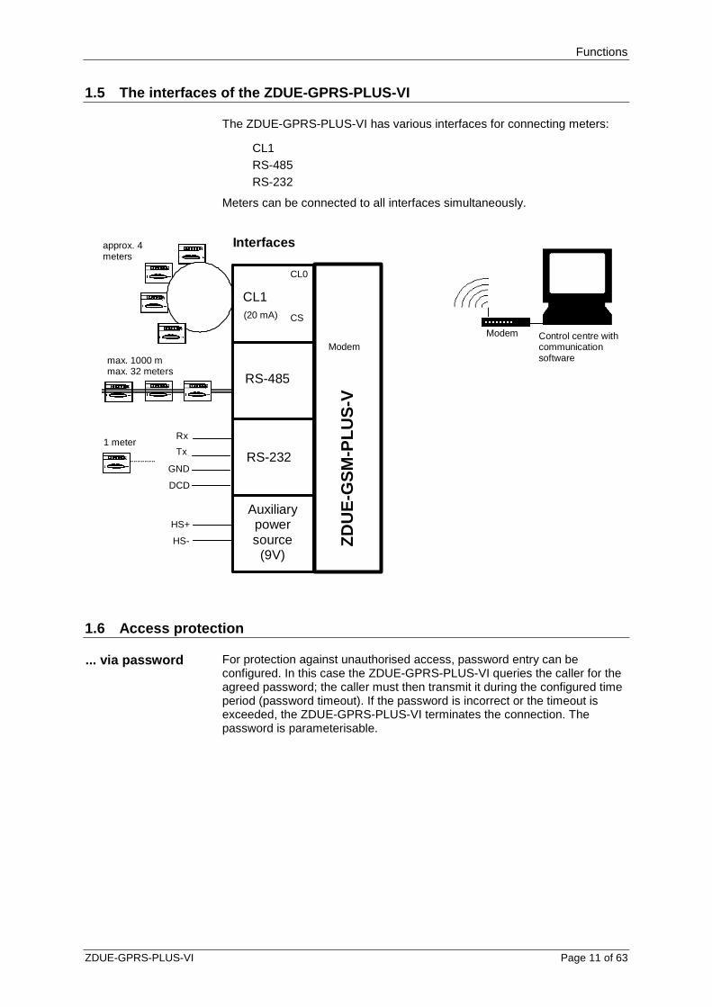
1.5 The interfaces of the ZDUE-GPRS-PLUS-VI
The ZDUE-GPRS-PLUS-VI has various interfaces for connecting meters:
CL1 RS-485 RS-232
Meters can be connected to all interfaces simultaneously.
CL1
RS-485
RS-232
Rx
Tx
GND
DCD
max. 1000 m max. 32 meters
approx. 4 meters
CL0
CS (20 mA)
Interfaces
Control centre with communication software
Modem
ZD
UE
-GS
M-P
LUS
-V
1 meter
Modem
Auxiliary power source
(9V)
HS+
HS-
1.6 Access protection
... via password For protection against unauthorised access, password entry can be configured. In this case the ZDUE-GPRS-PLUS-VI queries the caller for the agreed password; the caller must then transmit it during the configured time period (password timeout). If the password is incorrect or the timeout is exceeded, the ZDUE-GPRS-PLUS-VI terminates the connection. The password is parameterisable.
Functions
Page 12 of 63 ZDUE-GPRS-PLUS-VI
1.7 Timer and module reset
Although the ZDUE-GPRS-PLUS-VI does not have a real-time clock, a timer is operated on the basis of and with the accuracy of the processor crystal.
This timer controls the automatic module reset function that can be activated and configured in parameter class 79.
The automatic reset cycle starts when the device is switched on, i.e. the first module reset takes place after the parameterised period elapses after the device is started. Additional module resets then follow at the time intervals determined by the parameterised period.
The time for the daily watchdog (which is likewise configured in parameter class 79) is not used by the ZDUE-GPRS-PLUS-VI.
1.8 Configuration (parameterisation) and firmware u pdate
Configuration by software
Configuration is performed using configuration software, e.g. Dr. Neuhaus ZDUEset. Parameterisation commands are transmitted to the ZDUE-GPRS-PLUS-VI with the aid of this software.
The parameterisation commands can be transmitted to the ZDUE-GPRS-PLUS-VI via the GSM network (remote configuration) or directly via the RS-232 interface (local configuration).
Configuration by DIP switch
Using the DIP switch inside the ZDUE-GPRS-PLUS-VI the operation mode of the ZDUE-GPRS-PLUS-VI can be switched between Meter-Mode and AT-Mode. Refer to chapter 5.1 and 5.2.
Firmware update A firmware update can be performed via the configuration software (e.g. Dr. Neuhaus ZDUEset) from a computer that is connected locally directly to the RS-232 interface of the ZDUE-GPRS-PLUS-VI.

Operating elements, Connections and function indicators
ZDUE-GPRS-PLUS-VI Page 13 of 63
2 Operating elements, Connections and function indi cators
2.1 Internal components of the device
To insert the SIM card and to change the device settings via DIP switch, the device must be opened. The following diagram provides an overview of the internal components of the device that are important for the user:
1 GSM Status/Error LED
2 Status-LED
3 Service connector
4 DIP switch
5 SIM card holder
6 SMA antenna connector
7 Service button
8 Terminal block (RS485)
9 RS232 interface
I0 Terminal block
11 Current Loop LED
2.2 Service button
The service button (see 2.1, (7)) can be used both to reset all device parameters to the factory setting, and as a simple way to read their firmware version. The service button is only effective in meter mode.
Resetting to factory setting
Pressing the service button once and holding it for more than five seconds in ongoing operation deletes the parameterisation set in the device via EN62056-21 commands. When the button is released the ZDUE-GPRS-PLUS-VI is restarted, and when it boots it adopts the settings according to firmware defaults.
Outputting the firmware version during booting
If the service button is held down during switch-on , the ZDUE-GPRS-PLUS-VI outputs the current firmware version of the device via the serial interface.
The data format of the connected terminal softare has to be set to 19200 Baud 8N1.
2.3 DIP Switch
The DIP switch allows toggling between Meter Mode and AT-Mode. Refer to chapter 5.

Operating elements, Connections and function indicators
Page 14 of 63 ZDUE-GPRS-PLUS-VI
2.4 LEDs
The device is equipped with 3 LEDs for checking the operating status. They service to indicate the functions being executed at the moment and the respective status.
LED Colour / Action Meaning
Power • Green & Yellow with light pipe
Continuously green Operating voltage present
Continuously yellow GSM module on
Status/Error • Orange
3s on / 3 x flashing briefly Boot phase, searching for network
3s on / 2 x flashing briefly Fault state
3s on / 1 x flashing briefly SIM/PIN error
3s off / 1x flashing briefly Field strength <= -98 dBm
3s off / 2x flashing briefly -98 dBm < field strength <= -83 dBm
3s off / 3x flashing briefly -83 dBm < field strength <= -68 dBm
3s off / 4x flashing briefly Field strength > -68 dBm
Continuously on CSD connect
• Off Field strength unknown
Current Loop • Green CL meter(s) is/are connected or CL interface is jumpered
• Off Current loop is interrupted

Operating elements, Connections and function indicators
ZDUE-GPRS-PLUS-VI Page 15 of 63
2.5 Connections on the terminal block, RJ45 jack
The ZDUE-GPRS-PLUS-VI is connected to the power supply, and the meters are connected to the ZDUE-GPRS-PLUS-VI, by means of the 9-pole terminal block (power supply, auxiliary voltage, CL, RS-485) and an RJ45 jack (RS-232).
L N HS- HS+ RTX- RTX+ RT- RT+RJ45
Terminal block: PIN no. Signal Function/Comment
1 L Mains voltage connection 2 N Mains voltage connection 3 Not used 4 HS- Auxiliary voltage - 5 HS+ Auxiliary voltage + 6 RTX- Current Loop CL1 - 7 RTX+ Current Loop CL1 + 8 RT- RS-485 RT- 9 RT+ RS-485 RT+
RJ45:
2 DSR Positive RS-232 voltage (output; always active) 4 GND Signal GND / cable shield 5 TxD RS-232 TxD (output) 6 RxD RS-232 RxD (input)
Setup
Page 16 of 63 ZDUE-GPRS-PLUS-VI
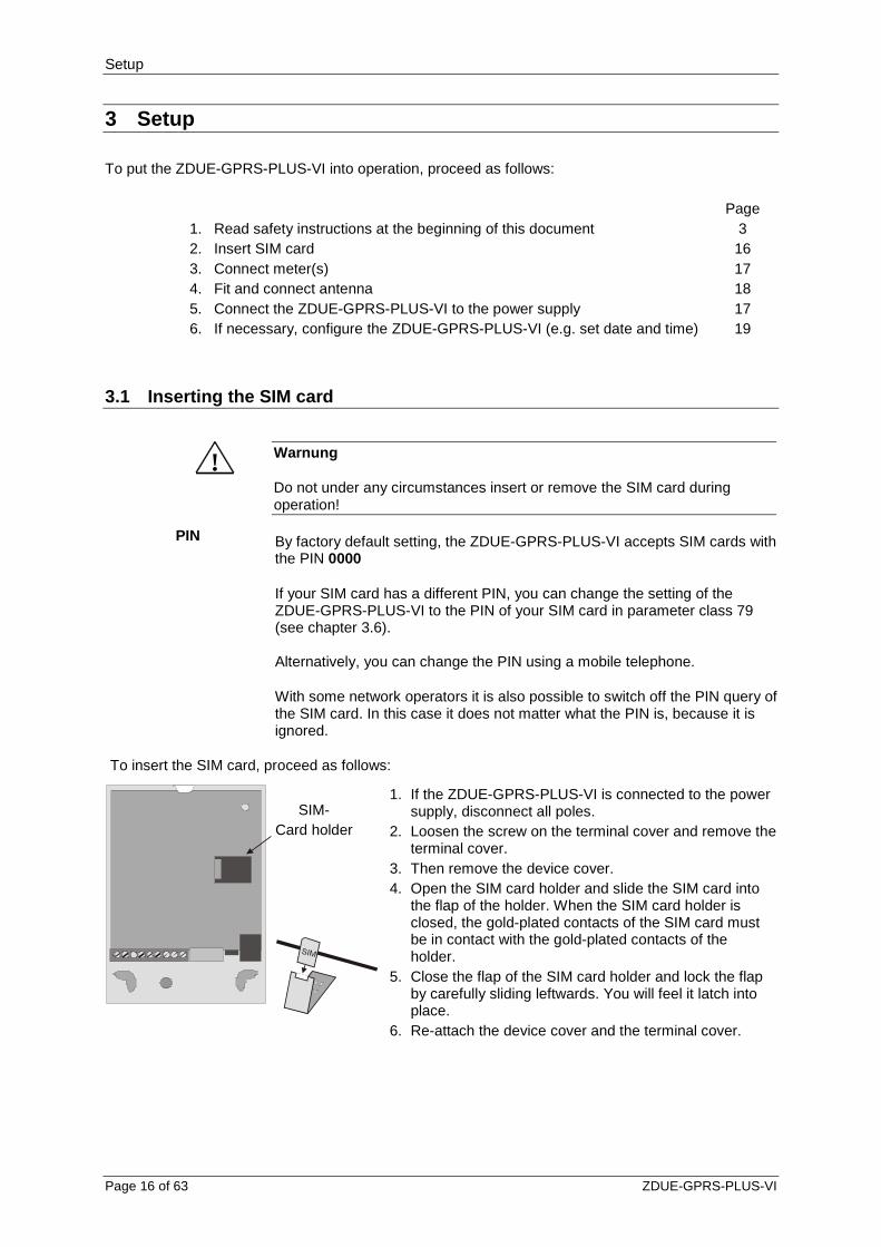
3 Setup To put the ZDUE-GPRS-PLUS-VI into operation, proceed as follows: Page 1. Read safety instructions at the beginning of this document 3 2. Insert SIM card 16 3. Connect meter(s) 17 4. Fit and connect antenna 18 5. Connect the ZDUE-GPRS-PLUS-VI to the power supply 17 6. If necessary, configure the ZDUE-GPRS-PLUS-VI (e.g. set date and time) 19
3.1 Inserting the SIM card
! Warnung
Do not under any circumstances insert or remove the SIM card during operation!
PIN By factory default setting, the ZDUE-GPRS-PLUS-VI accepts SIM cards with the PIN 0000
If your SIM card has a different PIN, you can change the setting of the ZDUE-GPRS-PLUS-VI to the PIN of your SIM card in parameter class 79 (see chapter 3.6). Alternatively, you can change the PIN using a mobile telephone.
With some network operators it is also possible to switch off the PIN query of the SIM card. In this case it does not matter what the PIN is, because it is ignored.
To insert the SIM card, proceed as follows:
1. If the ZDUE-GPRS-PLUS-VI is connected to the power supply, disconnect all poles.
2. Loosen the screw on the terminal cover and remove the terminal cover.
3. Then remove the device cover. 4. Open the SIM card holder and slide the SIM card into
the flap of the holder. When the SIM card holder is closed, the gold-plated contacts of the SIM card must be in contact with the gold-plated contacts of the holder.
5. Close the flap of the SIM card holder and lock the flap by carefully sliding leftwards. You will feel it latch into place.
6. Re-attach the device cover and the terminal cover.
SIM- Card holder
Setup
ZDUE-GPRS-PLUS-VI Page 17 of 63
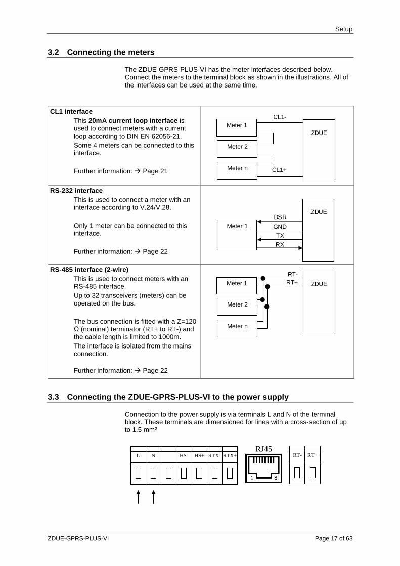
3.2 Connecting the meters
The ZDUE-GPRS-PLUS-VI has the meter interfaces described below. Connect the meters to the terminal block as shown in the illustrations. All of the interfaces can be used at the same time.
CL1 interface This 20mA current loop interface is used to connect meters with a current loop according to DIN EN 62056-21. Some 4 meters can be connected to this interface. Further information: Page 21
ZDUE
Meter 1
CL1+
Meter 2
Meter n
CL1-
RS-232 interface
This is used to connect a meter with an interface according to V.24/V.28. Only 1 meter can be connected to this interface. Further information: Page 22
ZDUE
Meter 1
TX
RX
DSR
GND
RS-485 interface (2-wire)
This is used to connect meters with an RS-485 interface. Up to 32 transceivers (meters) can be operated on the bus. The bus connection is fitted with a Z=120 Ω (nominal) terminator (RT+ to RT-) and the cable length is limited to 1000m. The interface is isolated from the mains connection. Further information: Page 22
ZDUE Meter 1
Meter 2
Meter n
RT- RT+
3.3 Connecting the ZDUE-GPRS-PLUS-VI to the power s upply
Connection to the power supply is via terminals L and N of the terminal block. These terminals are dimensioned for lines with a cross-section of up to 1.5 mm²
L N HS- HS+ RTX- RTX+ RT- RT+
RJ45

Setup
Page 18 of 63 ZDUE-GPRS-PLUS-VI
The ZDUE-GPRS-PLUS-VI can be operated with either AC or DC voltage.
Power supply Nominal values Maximum values AC voltage: 100VAC to 230VAC without
changeover (50/60 Hz) 76VAC to 253VAC
DC voltage (protected against polarity reversal):
60VDC to 100VDC without changeover
54VDC to 110VDC
The device conforms to protection class 2. The power supply to the
interfaces is electrically isolated from the electronics.
3.4 Fitting and connecting the antenna
The antenna is connected to the type SMA antenna jack. The position of the antenna connection may vary depending on the device type. The antenna must be installed in such a way that adequate signal quality is achieved. Make sure that there are no large metal objects in close to the antenna (e.g. reinforced concrete), as they may have an adverse effect on the signal quality. If an exterior antenna is mounted out of doors, its support bracket must be earthed for protection against lightning. Have this work done by qualified personnel! Observe the instructions included with your antenna.
Antenna characteristics
The antenna that is used should have an impedance of about 50 ohms. The antenna must be adapted to the frequency bands of the GSM network operator you have chosen: 850 MHz, 900 MHz, 1800 MHz or 1900 MHz.
In Europa and China GSM 900MHz snd DCS 1800MHz are used, in USA GSM 850 MHz and PCS 1900 MHz are used. Please ask your network operator.
The match (VSWR) of the antenna must be 1:2.5 or better.
Use only antennas from the accessories for the ZDUE-GPRS-PLUS-VI. Other antennas could interfere with product characteristics or even lead to defects.
Antenna connection

Setup
ZDUE-GPRS-PLUS-VI Page 19 of 63
3.5 Configuring the device if necessary
Basic settings as shipped
The ZDUE-GPRS-PLUS-VI is shipped with a predefined factory setting. Depending on requirements, it may need to be reconfigured. This can be done :
remotely via a CSD connection locally via the RS-232 interface (if no active CSD connection is
present).
Configuration options
Among other things, the password protection, interface speeds, data formats and the PIN that is to used can be parameterised.
For detailed information on parameterisation, see the chapter 6.
3.6 Parameterising the SIM PIN
Parameterisation options
The PIN can be set
remotely via a CSD connection locally via the RS-232 interface (if no active CSD connection is
present).
For detailed information on parameterisation, see the chapter , see the chapter 6.
SIM cards that have no PIN
With SIM cards that have no PIN, the PIN query is skipped; the GSM module does not wait for the PIN to be entered, but rather tries to check into the GSM network directly.
Response to a correct SIM PIN
If the PIN function of the SIM card being used is activated, and the PIN on the SIM card being used agrees with the parameterised PIN, then the device automatically tries to check into the GSM network.
Response to an incorrect SIM PIN
If the PIN verification fails, it is repeated one time. If the repeated PIN verification also fails, the device is blocked for further attempts (PIN ERROR status), meaning that operation is no longer possible even with a SIM card with the correct number. The Status/Error LED indicates a SIM/PIN error (see 2)
This status is retained after the power supply is disconnected and reconnected. This prevents the SIM card from being blocked if a third failed attempt is made, after which it could only be unblocked using the PUK (Personal Unblocking Key).
Unblocking the device
To unblock the ZDUE-GPRS-PLUS-VI, a SIM card with a deactivated PIN function must be inserted in the device. After starting, the device attempts to check into the GSM network, and the PIN ERROR status is also reset.
Alternatively, the ERROR status can be reset using the service command for setting a new PIN (see 6.5.7). This simultaneously sets the PIN parameterised in the device.

Interfaces
Page 20 of 63 ZDUE-GPRS-PLUS-VI
4 Interfaces
4.1 The GSM interface
Characteristics Communication with the GSM network takes place via an integrated GSM module. Data transmission is according to the following standards:
GSM Rec. 7.02 asynchronous, RLP acc. to GSM Rec. 4.22,
Analogue modem type V.32 or ISDN type V.110
4.2 Meter interfaces
Characteristics
The meter interfaces of the ZDUE-GPRS-PLUS-VI are all parameterised jointly, i.e. so that all of the interface parameter settings apply equally for all meter interfaces.
The following values are supported by the meter interfaces:
Data format:
Default: 7E1
Settable: 7E1, 8N1, 8E1
Handshake: No hardware/software handshake.
Interface speed:
Default: 300 baud (Mode C)
Settable: 300, 600, 1200, 2400, 4800, 9600, 19200, 38400 baud.
The speed of the meter interfaces should not exceed the speed of the GSM connection (9600 bit/s), because otherwise data loss may occur.
Number of meters
Meters can be connected to and operated on all of the interfaces at the same time, but only up to the specified maximum numbers.
In communication with the connected meters, all of the interfaces are addressed simultaneously, i.e. no application (e.g. control centre) can address any interface selectively. This means that unique addressing of the meters is essential in order to prevent the transfer of data by several meters at the same time.
Interfaces
ZDUE-GPRS-PLUS-VI Page 21 of 63
Procedure for communication between control centre and meter
Fixed baud rate:
The speed is set to a fixed value via a parameter setting. The respective meters that are communicating and the control centre connected via modem exchange the data at the selected speed, i.e. the ZDUE-GPRS-PLUS-VI works transparently. The speed does not exceed the GSM speed (9600 bit/s), or may be less.
Variable baud rate:
Corresponds to the baud rate changeover as per Mode C according to DIN EN 62056-21.
The starting speed is 300 baud. The speed is increased if the communicating meter requests it from the corresponding interface, and the interface confirms the requested baud rate. If there is no confirmation, the communication continues at the current speed.
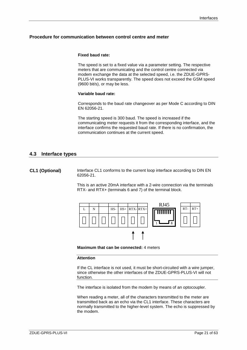
4.3 Interface types
CL1 (Optional) Interface CL1 conforms to the current loop interface according to DIN EN 62056-21.
This is an active 20mA interface with a 2-wire connection via the terminals RTX- and RTX+ (terminals 6 and 7) of the terminal block.
L N HS- HS+ RTX- RTX+ RT- RT+RJ45
Maximum that can be connected: 4 meters
Attention
If the CL interface is not used, it must be short-circuited with a wire jumper, since otherwise the other interfaces of the ZDUE-GPRS-PLUS-VI will not function.
The interface is isolated from the modem by means of an optocoupler.
When reading a meter, all of the characters transmitted to the meter are transmitted back as an echo via the CL1 interface. These characters are normally transmitted to the higher-level system. The echo is suppressed by the modem.
Interfaces
Page 22 of 63 ZDUE-GPRS-PLUS-VI
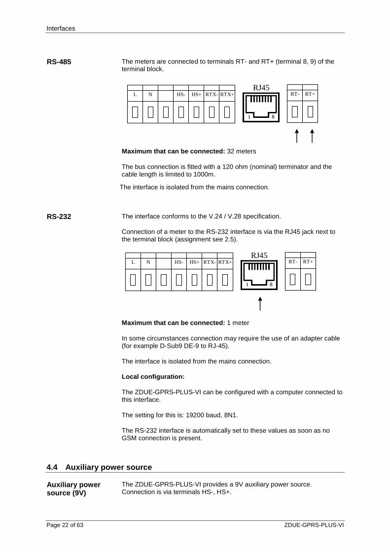
RS-485 The meters are connected to terminals RT- and RT+ (terminal 8, 9) of the terminal block.
L N HS- HS+ RTX- RTX+ RT- RT+RJ45
Maximum that can be connected: 32 meters
The bus connection is fitted with a 120 ohm (nominal) terminator and the cable length is limited to 1000m.
The interface is isolated from the mains connection.
RS-232 The interface conforms to the V.24 / V.28 specification.
Connection of a meter to the RS-232 interface is via the RJ45 jack next to the terminal block (assignment see 2.5).
L N HS- HS+ RTX- RTX+ RT- RT+RJ45
Maximum that can be connected: 1 meter
In some circumstances connection may require the use of an adapter cable (for example D-Sub9 DE-9 to RJ-45).
The interface is isolated from the mains connection.
Local configuration:
The ZDUE-GPRS-PLUS-VI can be configured with a computer connected to this interface.
The setting for this is: 19200 baud, 8N1.
The RS-232 interface is automatically set to these values as soon as no GSM connection is present.
4.4 Auxiliary power source
Auxiliary power source (9V)
The ZDUE-GPRS-PLUS-VI provides a 9V auxiliary power source. Connection is via terminals HS-, HS+.

Interfaces
ZDUE-GPRS-PLUS-VI Page 23 of 63
L N HS- HS+ RTX- RTX+ RT- RT+RJ45
The auxiliary power source is not available in all variants of the ZDUE-
GPRS-PLUS-VI.
The auxiliary power source may not be loaded with more than 100mA.

Operation
Page 24 of 63 ZDUE-GPRS-PLUS-VI
5 Operation
5.1 AT Mode
To enter the AT mode disconnect the device from mains and set the DIP switch (2.3) to „ON“. Connect the device to mains again.
If the AT mode is active, the GSM module inside the ZDUE-GPRS-PLUS-VI can directly be controlled by AT-Befehl entered at the meter interface. By it the ZDUE-GPRS-PLUS-VI can for example be used as a GSM terminal adapter for data connections via the GSM network.
After pushing the service button while the ZDUE-GPRS-PLUS-VI is in the meter mode and switching back into the the AT mode, the meter inferface is setup to:
19200 bit/s, 8N1
Swich into the meter mode to change the bitrate (eg. From 19200 bit/s to 9600 bit/s). Switch back into the AT mode.
If in meter mode after pushing the service nbutton another bitrate (start bit rate) is selected, this bitrate is also vald after switching into the AT mode
In AT-Modus always the character format 8N1 is used.
A remote configuration is not possible in AT mode.
To activate the automatic answer, please enter the AT commad ATS0=1.
Attention
Please take care, that the hardware handshake (RTS/CTS) of the terminal software needs to be switched off.
Attention
Do not modify in any case the baudrate of the GSM engine by AT command!

Operation
ZDUE-GPRS-PLUS-VI Page 25 of 63
5.2 Meter Mode
To enter the meter mode disconnect the device from mains and set the DIP switch 2.3) to „OFF“. Connect the device to mains again.
In the meter mode the ZDUE-GPRS-PLUS-VI accepts automatically incoming calls from the central station and connects transparently the connected meters with the central station. The start bitrate at the meter interfaces is set by parameters to a fix value. The meter which communicates and the central station exchange directly the data, i.e. the ZDUE-GPRS-PLUS-VI just passes through the data between central station and meter.
If EN 62056-21 mode C is activated, the ZDUE-GPRS-PLUS-VI adapts the bitrate, but does not modify the data content.
The ZDUE-GPRS-PLUS-VI can be configured remotely via the GSM connection using configuration commands in accordance to DIN EN 62056-21.
5.3 Controlling according to EN62056-1
Control characteristics
The ZDUE-GPRS-PLUS-VI controls the communication between the control centre and the meters that are connected to the ZDUE-GPRS-PLUS-VI in accordance with protocol EN 62056-21 (Annex A):
in A/C mode,
in data readout and programming mode
including data saving (receiving) and acknowledgement.
The starting baud rate and the data format can be set for the following interfaces: CL1 (Current Loop interface), RS-232, RS-485
Please note that these meter interface settings apply equally for all interfaces.
In mode C-Operation the baud rate is changed over according to the baud rate ID contained in the acknowledge telegram of the control centre.
Detecting the end of a communication cycle
When reading data, the end of a communication cycle is detected when
>= 3 seconds no meter data is received (Mode A/C timeout)
the sequence ‘CR LF ETX‘ is detected (Mode C regular end)
In programming mode, the end of a communication cycle is detected when
a ‘Break‘ telegram is detected (Mode A/C break).
When a communication cycle is completed, the connection is terminated and the baud rate of the serial interface driver of the meter interfaces is reset to the parameterised start value.
Operation
Page 26 of 63 ZDUE-GPRS-PLUS-VI
Regular connection termination
Termination of connection after transfer timeout:
The ZDUE-GPRS-PLUS-VI terminates a regular data connection after the end of the transfer timeout. What this means is: For an existing connection, if no data transfer takes place between the control centre and the ZDUE-GPRS-PLUS-VI or the meters connected to the ZDUE-GPRS-PLUS-VI within the specified timeout (default: 99 seconds), then the ZDUE-GPRS-PLUS-VI terminates the connection.
Termination of connection by the control centre:
The control centre can itself terminate a connection at any time.

Configuration
ZDUE-GPRS-PLUS-VI Page 27 of 63
6 Configuration
Security settings
Password
Data format and transmission speed of the meter interfaces
The most important configurable settings and functions
GSM module reset
6.1 Configuration by software
Configuration is performed with the software that is used for operation of the control centre or a configuration software (e.g. Dr. Neuhaus ZDUEset). Parameterisation commands are transmitted to the ZDUE-GPRS-PLUS-VI with the aid of this software.
The software commands are described starting on page 33.
The parameterisation commands can be transmitted to the ZDUE-GPRS-PLUS-VI via the GSM network (remote configuration) or directly via the RS-232 interface (local configuration).
Remote configuration via the GSM network
Remote configuration is performed by the control centre, which transmits parameterisation commands to the ZDUE-GPRS-PLUS-VI via the GSM network. Transmission takes place according to DIN EN 62056-21 with BCC secured protocol.
The parameterisation commands must be transmitted explicitly to the address of the ZDUE-GPRS-PLUS-VI.
The following device address is preset at the factory: 99999999
The device address is configurable. It can contain up to 16 characters; numbers and letters are permitted.
Local configuration The device can also be configured with the aid of a computer that is connected via its COM port directly to the RS-232 interface of the ZDUE-GPRS-PLUS-VI.
Precondition:
No GSM connection exists between ZDUE-GPRS-PLUS-VI and control centre.
GSM offline status: Settings of the RS-232 interfac e
As soon as no GSM connection exists, the RS-232 interface is set by default to the following setting:
19200 baud 8 data bits, No Parity, 1 stop bit

Configuration
Page 28 of 63 ZDUE-GPRS-PLUS-VI
Make sure that on the configuration computer that is connected the settings of the COM port being used agree with this, and switch off all flow controls (hardware (RTS/CTS), XON-XOFF).
If the computer connected to the RS-232 interface transmits prompting telegrams with the device address of the ZDUE-GPRS-PLUS-VI (default: 99999999), the ZDUE-GPRS-PLUS-VI responds exactly as if it received the prompting telegram from the remote control centre via the GSM network.
During local configuration via the RS-232 interface the ZDUE-GPRS-PLUS-VI does not accept any calls from the GSM network.
GSM online status: Settings of the RS-232 interface
As soon as a GSM connection is established, the RS-232 interface switches to the bitrate and data format being configured for the meter mode Factory default is::
300 bit/s, 7E1, Mode C
The settings of the RS-232 interface for the GSM online status are configurable
Attention
Please note that the RS-232 interface is only used if something is connected to the current loop (it has at least one meter connected or a wire jumper between the two current loop terminals RTX- and RTX+). In this case the current loop LED must light up (see 2.1).
6.2 Parameters
The following table provides an overview of the basic parameter classes contained in the ZDUE-GPRS-PLUS-VI. These classes are assigned to numbers, which must also be specified in parameterisation commands.
Class
Permitted access types (R=Read/W=Write)
Summer/Winter time changeover times (imple-mented for compatibility reasons only, see 6.3.1)
54 R/W
Operating parameters 79 R/W
Parameters can only be written by writing a complete class (i.e. an offset and length must also be specified with ‘0000‘ in a parameterisation command).
When a class is expanded the new parameters must be appended in order to ensure downward compatibility.

Configuration
ZDUE-GPRS-PLUS-VI Page 29 of 63
Each parameter class includes a range that is reserved for possible expansions. Parameter expansions that are covered by these reserved ranges do not lead to any incompatibility between different firmware versions. If the expansion space is not sufficient, a new parameter class must be created. This likewise does not lead to any incompatibility, because a command to set/read this new parameter class from an older firmware will be acknowledged with ERROR. The reserved parameter ranges are filled in with ‘0‘ (0x30) during communication.
6.3 Parameter classes
In the following the parameters are sorted by classes and shown in the same way as their notation in parameterisation commands. The respective factory configuration is highlighted in bold . The specifications Offset, Len and Values (ASCII) have the following meanings
Offset Contains the relative address of a parameter within the
parameter class, relative to the class structure. Len Reflects the number of ASCII characters that are
necessary to depict the parameter during communication. For strings only the number of ASCII characters defined with ‘String Length‘ is significant (decimal-coded); any string range that is not used must be filled in.
Values (ASCII) Contains permissible values (ranges) for the individual parameters during reading (W1 command) and reading by means of an R3 command.
6.3.1 Parameter class 54
This class is implemented only for compatibility reasons. In other models it specifies the changeover times of the clock from summer time to standard time and from standard time to summer time. However, because the ZDUE-GPRS-PLUS-VI does not have a real-time clock, the parameter class 54 has no significance for operation of the ZDUE-GPRS-PLUS-VI. The parameters of this class are read-only.
6.3.2 Parameter class 79
This class describes the general operating parameters of the ZDUE-GPRS-PLUS-VI. It is defined as an open class, i.e. data sets that are longer than what is defined here are accepted. The non-specified values are ignored in evaluation by the device. When the parameters are read only the specified values are output.
Length of the class 79 data set: 124 bytes
Class 79
Parameters Offset Len Values (ASCII) Description
String length Power supply company identification
0 2 ‘01‘ .. ‘16‘ Factory configuration: ‘08‘
Power supply company identification
2 16 ‘ ‘ .. ‘~‘, (0x20..0x7E)
‘00000000‘ / Power supply company identification of the
Configuration
Page 30 of 63 ZDUE-GPRS-PLUS-VI
Class 79 Parameters
Offset Len Values (ASCII) Description
ZDUE-GPRS-PLUS-VI in the accounting data set.
String length of device address (IEC address)
18 2 ‘01‘ .. ‘16‘ Factory configuration: ‘08‘
Device address ZDUE-GPRS-PLUS-VI
20 16 (‘0‘ .. ‘9‘, ‘a‘ .. ‘z‘, ‘A‘ .. ‘Z‘)
‘99999999‘
String length of set password 36 2 ‘00‘ .. ‘16‘ Factory configuration: ‘08‘
Set password 38 16 ‘ ‘ .. ‘~‘ (20h .. 7Eh) without ‘(‘ , ‘)‘
‘00000000‘
Control centre password active 54 1 ‘0‘ No password protection ‘1‘ Password without callback String length of control centre password
55 2 ‘00‘ .. ‘16‘ Length of the control centre password
Control centre password 57 16 ‘ ‘ .. ‘~‘ (20h .. 7Eh)
Factory configuration: empty
String length of communication ID
73 2 ‘01‘ .. ‘16‘ Factory configuration: ‘15‘
Communication ID 75 16 ‘ ‘ .. ‘~‘ (20h .. 7Eh)
‘1KGL923390R0003 ‘
Data format to meter interface 91 1 ‘0‘ 7 data bits, Even Parity, 1 stop bit
‘1‘ 8 data bits, No Parity, 1 stop bit ‘2‘ 8 data bits, Even Parity, 1 stop
bit Mode C monitoring 92 1 ‘0‘ Meter changeover, external
meters according to IEC61107 as per Mode C is monitored
‘1‘ Purely transparent data operation with fixed baud rate acc. to start baud rate.
Transfer timeout [seconds] 93 2 ‘10‘ to ‘99‘ 10 to 99 seconds factory configuration: ‘99‘
Call answering delay 95 2 ‘01‘ .. ‘15‘ is ignored (always '01' ) Start baud rate 97 1 ‘0‘ 300 baud ‘1‘ 600 baud ‘2‘ 1200 baud ‘3‘ 2400 baud ‘4‘ 4800 baud ‘5‘ 9600 baud ‘6‘ 19200 baud ‘7‘ 38400 baud ‘8‘ 57600 baud (optional) Bearer service 98 2 ‘00‘ Autobauding, ‘07‘ 9600bps(V.32), ‘08‘ 14400bps(V.34), ‘09‘ 9600bps(V.110), ‘10‘ 14400bps(V.110) Data saving/compression 100 1 ‘0‘ RLP ‘1‘ non-RLP Country code 101 2 ‘00‘ Reserve, not in use
Configuration
ZDUE-GPRS-PLUS-VI Page 31 of 63
Class 79 Parameters
Offset Len Values (ASCII) Description
Daily watchdog 103 1 ‘0‘ activated, the device notices the watchdog
‘1‘ no daily watchdog activated Time for daily watchdog 104 4 ‘2100‘ The watchdog interval starts
daily at this time, relative to the device time
Interval for watchdog 108 1 ‘0‘ every 24 hours ‘1‘ watchdog every 12 hours ‘2‘ watchdog every 6 hours ‘3‘ watchdog every 3 hours ‘4‘ watchdog every 2 hours ‘5‘ watchdog every 1 hour Data format to control centre1 109 1 ‘0‘ Data format 7E1 (simulated)
‘1‘ Data format 8N1 String length of PIN 110 1 ‘0‘ .. ‘9‘ Factory configuration: ‘4‘ PIN2 111 9 (‘0‘ .. ‘9‘) Factory configuration: ‘0000‘ Operator Set Mode 120 1 ‘0‘ Automatic:
roaming permitted ‘1‘ Manual:
no roaming permitted! ‘4‘ Manual / Automatic:
Roaming permitted, but GSM module is if necessary stopped cyclically (Operator Set Delay) in order to check into the home network (GSM Net ID = first 5 digits of the IMSI).
Operator Delay Set 121 2 ‘15‘ .. ‘99‘ Interval [in minutes] for module request ‘Operator Select‘, if the parameterised and actual operator are different.
Cyclical query of the call forwarding
123 1 ‘0‘ Query of the call forwarding is active
‘1‘ Query of the call forwarding is passive
1 In the reception path the ZDUE-GPRS-PLUS-VI evaluates all characters in the data format 7N. This applies to Mode C monitoring and the addressing and communication with the ZDUE-GPRS-PLUS-VI (address "99999999"). The set data format is used in the transmission path to the control centre (regardless of the application interface). A consequence of this function is that it does not matter for the parameterisation of the ZDUE-GPRS-PLUS-VI which data format is set at the control centre or in the modem. 2 As long as the device has the status "PIN without errors", the PIN is changed accordingly both in the device and on the SIM. The change is performed in service operation immediately after the transfer command for parameters. In CSD operation the PIN is saved on the SIM and in the device immediately after it is applied. The new PIN is saved in the device parameters only after the PIN has been successfully changed on the SIM.
Configuration
Page 32 of 63 ZDUE-GPRS-PLUS-VI
6.4 Register data set of the ZDUE-GPRS-PLUS-VI
6.4.1 General
The ZDUE-GPRS-PLUS-VI contains a short set for register data. Output is made using the DIN EN62056-21 protocol. The register data set is structured according to the following table.
EDIS identifier Field length Format Function 1-1:F.F 8 Hexadecimal Error status 1-1:0.0.0 16 (def. 8) Character string Power supply company identification 1 1-1:0.2.0 8 Character string Firmware version of the ZDUE-GPRS-PLUS-VI 1-1:0.9.1 6 hhmmss Time 1-1:0.9.2 6 YYMMDD Date 1-1:C.91.0 15 Character string Firmware version of the GSM module 129-72:23.7.0 15 Character string Current IP address in GPRS operation3
The register data set of the ZDUE-GPRS-PLUS-VI receives the values for time and date that have previously been written with the corresponding set command. If no time or no date has been set yet, or if the device was deenergised, then "0000000" is output as the time and/or date respectively.
Example: Accounting data of the ZDUE-GPRS-PLUS-VI
1-1:F.F (00000005) Error status
1-1:0.0.0 (12345678) Power supply company ID
1-1:0.2.0 ( 4.016) Firmware version of the ZDUE
1-1:0.9.1 (135224) Time (hhmmss)
1-1:0.9.2 (110326) Date (yymmdd)
1-1:C.91.0 (REVISION 01.002) Firmware version of GSM module
129-72:23.7.0 () [own IP address]3
!
T
3 This register is only relevant for GPRS operation in the ZDUE-GPRS-PLUS-VI (see Section 7.4.4). If the ZDUE-GPRS-PLUS-VIis not operated in GPRS mode, it does not contain any value (empty brackets). If the ZDUE-GPRS-PLUS-VI is operated in GPRS mode, but it has not received any IP address from the provider, then the register is given the value "000.000.000.000".

Configuration
ZDUE-GPRS-PLUS-VI Page 33 of 63
6.4.2 Format of the error status
The value is the hexadecimal representation of a 32-bit number that is composed of the following status bits (in brackets is the bit no. in the operation status word, see the section Status commands):
Bit 0 (Bit 08): Power return
Bit 1 (Bit 09): reserved "0"
Bit 2 (Bit 10): Parameter reloaded
Bit 8 (Bit 04): Parameter checksum error
Bit 16 (Bit 05): Parameter read/write error
Bit 17 (Bit 06): reserved "0"
Bit 18 (Bit 07): reserved "0"
Bit 24 (Bit 00): reserved "0"
Bit 25 (Bit 01): reserved "0"
Bit 26 (Bit 02): reserved "0"
6.5 Communication commands according to DIN EN 6205 6-21
The following sections document the commands supported by the ZDUE-GPRS-PLUS-VI. The data set elements it contains are described in the following.
The command descriptions use symbolic data set elements (e.g. for time stamps). Their structure is the same for all command categories.
1. Time stamp ZS7:
yhhmmss
y = time zone (0=winter time, 1=summer time) hh = hour (00..23) mm = minute (00..59) ss = second (00..59)
2. Time stamp DS7:
yYYMMDD
y = time zone (0=winter time, 1=summer time) YY = year (00..99) MM = month (01..12) DD = day (01..31)
3. Set password: String with max. 16 characters, with the exception of the character '(', ')', '/', '!' or empty string

Configuration
Page 34 of 63 ZDUE-GPRS-PLUS-VI
6.5.1 Error messages
In unusual circumstances the ZDUE-GPRS-PLUS-VI answers a command with an error message: <STX>(ERRORnn)<ETX><BCC>
The following error numbers ‘nn‘ can be generated by the ZDUE-GPRS-PLUS-VI in this case:
Error number (nn) Error 00 Invalid command (data set structure, content) 01 Unknown command (command ID, command type ID) 02 03 04 Invalid class 05 06 07 08 09 10 11 Invalid time/date (impermissible values) 12 13 14 Serial number has already been set [W1-
S96(20)(<data>)]
6.5.2 Set password
For the execution of various commands, the transfer of a set password (as a 2nd data set) is necessary. Depending on the parameterisation, the following cases can arise in communication between ZDUE-GPRS-PLUS-VI and control centre:
No set password parameterised in the ZDUE-GPRS-PLUS-VI (string length = 0): In this case the ZDUE-GPRS-PLUS-VI will not perform any evaluation of the transmitted set passwords (all password-protected commands can be executed!). In this case, the request to transmit the password (P0 operand) when programming mode is activated may be answered with the password command (P1 command, password as desired). The control centre can, however, alternatively also continue the communication with the transfer of a different permissible VDEW command.

Configuration
ZDUE-GPRS-PLUS-VI Page 35 of 63
Set password parameterised in the ZDUE-GPRS-PLUS-VI (default: ‘00000000‘) All of the passwords transmitted by the control centre must be the same as the ones that were parameterised, otherwise the communication will be terminated by the ZDUE-GPRS-PLUS-VI by means of a break command. The request to transmit the password (P0 operand) when programming mode is activated must be answered with the password command (P1 command). The direct transmission of a different VDEW command is not permitted.
6.5.3 Parameterisation commands
The setting and reading of the parameters is performed via W1/R3 commands (ASCII-coded characters).
The class is used to select the individual parameter segments; the command parameters ‘offset‘ and ‘length‘ can in general be used to access individual parameter or parameter ranges. This is, however, not supported by the ZDUE-GPRS-PLUS-VI; the classes can only be read or written completely (‘offset‘ and ‘length‘ of the class equal to ‘0000‘).
W1 commands: 1. Write class (completely)
Command format: <SOH>W1<STX>C<class> 00000000(<data>) (set password)<ETX><BCC>
Example: Setting the parameters of the subgroup parameter class 79 to the following values:
Power supply company identification: ‘12345678’ Device address: ‘74747474’ Set password: ‘18871887’ Control centre password act.: ‘0’ Control centre password: ‘PW0’ Communication ID: ‘1KGL923390R0003’ Data format to meter: ‘1’ Mode C monitoring: ‘1’ Transfer timeout: ‘99’ ... (The other parameters correspondingly)
LS /?99999999!<CR><LF>
ZDUE /ABB61KGL923390R0003<CR><LF>
LS <ACK>061<CR><LF>
ZDUE <SOH>P0<STX>(00000001)<ETX><BCC>
LS <SOH>P1<STX>(00000000)<ETX><BCC>
ZDUE <ACK>
LS <SOH>W1<STX>C7900000000(0812345678000000000874747 4740000000008188718870000000000PW00000000000000151KG L923390R00030119901600000021000140000000001150)(000000 00)<ETX><BCC>
ZDUE <ACK>

Configuration
Page 36 of 63 ZDUE-GPRS-PLUS-VI
After this command is carried out, the data are initially stored in the volatile memory of the ZDUE-GPRS-PLUS-VI. In order to transfer them to non-volatile memory, the parameter transfer command W1P01() (see Section 6.5.4) must be executed.
R3 commands: 1. Read class in partial blocks
Command format: <SOH>R3<STX>C<class> 00000000( )<ETX><BCC>
Reply format: <STX>oooo(<data set>)[<EOT> | <ETX>]<BCC>
oooo = Offset (ASCII characters hexadecimal- coded)
<data set> = data of the class (max. 64 ASCII characters per partial block)
Example: Reading of class 79 with offset ‘0000‘, length ‘0000‘ (reading of the operating parameters -> multiple partial blocks required):
LS <CR><LF>
ZDUE /ABB61KGL923390R0003<CR><LF>
LS <ACK>061<CR><LF>
LS <CR><LF>
ZDUE <SOH>P0<STX>(00000001)<ETX><BCC>
LS <SOH>P1<STX>(00000000)<ETX><BCC><CR><LF>
ZDUE <ACK>
LS <SOH>R3<STX>C7900000000()<ETX>,<CR><LF>
ZDUE <STX>0000(0800000000000000000899999999000000000 80000000000000000003PW00000)<EOT><BCC>
LS <ACK><CR><LF>
ZDUE <STX>0040(000000000151KGL923390R000300099015000000 21000040000000001150)<ETX><BCC>
6.5.4 Parameter transfer command
In order for newly written parameters to be transferred at a specific point in time, the following command is defined.
Executing this command causes the data of the previously transmitted command "Write class" to be transferred to the non-volatile memory. The old parameters remain active before this command is executed.
If the data are read before transfer by means of this command, the old values will be output!
The transmission of a break deletes the data set temporarily in the device via class write commands. This way faulty "Write class" commands can be undone, so long as the W1 command defined here has not been transmitted. Moreover, the temporary data are discarded by a disconnect or the occurrence of an inactivity timeout.
Command format: <SOH>W1<STX>P01()(set password)<ETX><BCC>

Configuration
ZDUE-GPRS-PLUS-VI Page 37 of 63
6.5.5 Time/date commands
The time and date commands have no function in the ZDUE-GPRS-PLUS-VI. They are implemented for reasons of compatibility with other devices and control centre programs.
The reading of the time and/or date from the ZDUE-GPRS-PLUS-VI makes available the values that were written to the device previously with the commands Set time and/or Set date. These data are saved in the device only in volatile memory, and thus are no longer available after the power supply is disconnected.
If no time is set, "0000000" is returned as the time; if no date is set, "0070101".
Setting the time:
Command format: <SOH>W5<STX>0.9.1(ZS7)(set password) <ETX> <BCC>
Setting the date:
Command format:
<SOH>W5<STX>0.9.2(DS7)(set password) ETX> <BCC>
Reading the time:
Command format: <SOH>R5<STX>0.9.1()<ETX><BCC>
Reply format: <STX>0.9.1(ZS7)<ETX><BCC>
Reading the date:
Command format: <SOH>R5<STX>0.9.2()<ETX><BCC>
Reply format: <STX>0.9.2(DS7)<ETX><BCC>

Configuration
Page 38 of 63 ZDUE-GPRS-PLUS-VI
6.5.6 Status commands
Events and error messages are recorded in an "operation status word" in the ZDUE-GPRS-PLUS-VI. This is stored in volatile RAM, and is thus lost in the event of a power failure. The status word can be read from the device in order to determine the current operating status.
Bit in status
word Indicated fault state / event
Bit 0 Reserved
Bit 1 Reserved
Bit 2 Reserved
Bit 3 Reserved
Bit 4 Parameter checksum faulty (EEPROM)
Bit 5 EEPROM read/write error
Bit 6 Reserved
Bit 7 Reserved
Bit 8 Power return
Bit 9 Reserved
Bit 10 Reserved
Bit 11 Reserved
Bit 12 Reserved
Bit 13 Reserved
Bit 14 Reserved
Bit 15 Reserved
Additional status information that can be read from the ZDUE:
GSM field strength
GSM network operator ID (e.g. 26201 for T-Mobile)
GSM location area ID
GSM cell ID
IMEI (International Mobile station Equipment Identity): Serial number of the GSM module
IMSI (International Mobile Subscriber Identity): ID number of the SIM card
These value are queried from the ZDUE-GPRS-PLUS-VI via service command (see 6.5.7).
The ZDUE-GPRS-PLUS-VI enables the reading and resetting of the status word. During reading the highest-value bit is transmitted first; each bit is represented by an ASCII character ‘0‘ or ‘1‘.
Read status word:
Command format: <SOH>R3<STX>S70()<ETX><BCC>
Response: <STX>S70(b16b15b14 ...... b00)<ETX><BCC>
bnn : ‘0‘ = event/status has not occurred / inactive
‘1‘ = event/status has occurred / active

Configuration
ZDUE-GPRS-PLUS-VI Page 39 of 63
Example: Bit 8 (power return) is set in the status word.
LS /?99999999!<CR><LF>
LS <CR><LF>
ZDUE /ABB61KGL923390R0003<CR><LF>
LS <ACK>061<CR><LF>
ZDUE <SOH>P0<STX>(00000001)<ETX><BCC>
LS <SOH>P1<STX>(00000000)<ETX><BCC><CR><LF>
ZDUE <ACK>
LS <SOH>R3<STX>S70()<ETX><BCC><CR><LF>
ZDUE <STX>S70(0000000100000000)<ETX><BCC>
LS <SOH>B0<ETX><BCC><CR><LF>
Reset the status word:
Command format: <SOH>W1<STX>S70()<ETX><BCC>
6.5.7 Service commands
W1 commands:
Reset parameters to factory configuration:
This command is used to load the factory parameters. All customer-specific settings are overwritten.
Command format: <SOH>W1<STX>S98( )<ETX><BCC>
The overwritten parameters are saved in non-volatile memory. The device is then automatically rebooted.
This command is also permitted via the network (GSM interface, GPRS).
This command is executed immediately after receipt (without transmitting an additional break).
The manufacturer passwords and the manufacturer device addresses are not reset by this command.
Remote reset of the ZDUE-GPRS-PLUS-VI
This command provokes a warm restart of the device. The command leads to a watchdog reset followed by a restart of the firmware. No changes are made to the parameters.
Command format: <SOH>W1<STX>S92( ) (<set password>)<ETX> <BCC>
Response: <ACK>
This command is also permitted via the GSM interface

Configuration
Page 40 of 63 ZDUE-GPRS-PLUS-VI
Write PIN
This command sets the PIN in the device to the new value. The PIN on the card is not changed. Any PIN fault status that is present is cleared by this command.
Command format: <SOH>W1<STX>S93(<PIN_Len><PIN>)(<set password>) <ETX><BCC>
Response: <ACK>
The parameters have the following meaning here:
PIN_Len: Length of the PIN
PIN: PIN to be set
Set password: Set password parameterised in the ZDUE-GPRS-PLUS-VI.
This command is also permitted via the GSM interface.
R3 commands: Read parameter checksum
Command format: <SOH>R3<STX>S61( )<ETX><BCC>
Response: <STX>S61(cccc)<ETX><BCC>
cccc : Hex-coded 16-bit parameter checksum
This command is also permitted for the GSM interface.
Read firmware version of the ZDUE
Command format: <SOH>R3<STX>S63( )<ETX><BCC>
Reply (example): <STX>S63(ZDUE_PLUS_V_V4.017)<ETX><BCC>
This command is also permitted for the GSM interface.
Read firmware version of the GSM module
Command format: <SOH>R3<STX>S64( )<ETX><BCC>
Reply (example): <STX>S64(REVISION 01.002)<ETX><BCC>
This command is also permitted for the GSM interface.
Read version of the booter
Command format: <SOH>R3<STX>S96(14)<ETX><BCC>
Reply (example): <STX>S96(14)(<data>)<ETX><BCC>
This command is also permitted for the GSM interface.

Configuration
ZDUE-GPRS-PLUS-VI Page 41 of 63
Read position of the DIP switch/parameter status
Command format: <SOH>R3<STX>S96(15)<ETX><BCC>
Reply (example): <STX>S96(15)(ccccp)<ETX><BCC>
The parameters have the following meaning here:
cccc : Hex-coded 16-bit output p : Parameter status flag: 0 : User parameterisation active 1 : Default parameterisation active
This command is also permitted for the GSM interface.
Read GSM operating/module parameters:
Command format: <SOH>R3<STX>S65( )<ETX><BCC>
Reply (example): <STX>S65(dB)(Net-ID)(location)(Cell ID) (IMEI) (IMSI) <ETX><BCC>
The parameters have the following meaning here:
dB GSM field strength (3-digit, decimally coded, e.g.: ‘075’ => -75dBm, ‘na’ => not available)
Net ID Network ID of the GSM network operator (max. 6 digits, e.g.: ‘26202’),
Location GSM Location Area ID (max. 4-digit, hex-coded),
Cell ID GSM Cell D (max. 4 digits, hex-coded),
IMEI Serial number of the GSM module (International Mobile station Equipment Identity, max. 20 digits),
IMSI ID number of the SIM card (International Mobile station Equipment Identity, max. 20 digits).
This command is also permitted for the GSM interface.
Example (reply): <STX>S65(075)(26202)(019B)(6434)(357042000459777) (262023800175922)<ETX>
Configuration
Page 42 of 63 ZDUE-GPRS-PLUS-VI
Read unique serial number :
Command format: <SOH>R3<STX>S96(20)<ETX><BCC>
Reply (example): <STX>S96(20)( <date>;<Ser-no.>;<Lot no.>)<ETX><BCC>
The parameters have the following meaning here:
Date: Date in the format "YYYYMMDD" (e.g.: 20060830)
Ser. Number Max.12-digit serial no. (ASCII characters), leading zeros allowed
Lot number Max.34-digit lot no. (ASCII characters), leading zeros allowed
This command is also permitted for the GSM interface.

GPRS Modes
ZDUE-GPRS-PLUS-VI Page 43 of 63
7 GPRS Modes
In GPRS mode it is possible, as an alternative to communication via CSD, to establish a data connection via the GPRS network to the ZDUE-GPRS-PLUS-VI and the meters connected to it.
In this case the ZDUE-GPRS-PLUS-VI functions as an IP server to which an IP connection must be established from a client (e.g. a control centre).
Attention
In order to be able to operate the ZDUE-GPRS-PLUS-VI in GPRS mode, a SIM card enabled for GPRS must be used. Please consult your GSM provider if necessary.
7.1 Configuration
Configuration options
In addition to the configuration options of the ZDUE-GPRS-PLUS-VI in CSD mode, the ZDUE-GPRS-PLUS-VI in GPRS mode can be parameterised via an IP connection opened by a client.
Remote configuration via the GSM network
As in the ZDUE-GPRS-PLUS-VI, see Remote configuration via the GSM network, p. 27).
Local configuration As in the ZDUE-GPRS-PLUS-VI , see Local configuration, p. 27.
Remote configuration via GPRS (fixed IP service)
Configuration is performed using parameterisation software (control centre, configuration tool (e.g. Dr. Neuhaus ZDUEset, etc.). This transmits the parameterisation commands to the ZDUE-GPRS-PLUS-VI via the GPRS network. Transmission likewise takes place according to DIN EN 62056-21 with BCC secured protocol.
The parameterisation commands must be transmitted explicitly to the address of the ZDUE-GPRS-PLUS-VI. The following device address is preset at the factory: 99999999
The device address is configurable. It contains 16 characters; numbers and letters are permitted.

GPRS Modes
Page 44 of 63 ZDUE-GPRS-PLUS-VI
7.2 Behaviour for the GPRS dial-in
Provided that the parameterisation is correct, normally the device dials into the GPRS network automatically and then sets up the IP server, so long as GPRS mode is activated in class 82.
For example, faults in the GSM network or at the GPRS provider can cause the log-in and dial-in attempts of the ZDUE-GPRS-PLUS-VI to fail. To prevent the device from trying to establish a connection to the GPRS network continuously (and in some cases incurring costs in the process), the ZDUE-GPRS-PLUS-VI possesses two timers and a counter that can be used to control its behaviour in the event of such faults. These parameters are contained in parameter class 82 (see 7.4.3):
Counter: Number of dialling attempts to GPRS service before module reset
Timer 1: Connection timeout for a failed GPRS login attempt
Timer 2: Waiting time after x failed GPRS login attempts
Here the ZDUE-GPRS-PLUS-VI proceeds in two steps. If a GPRS login attempt fails, the number of login attempts defined in Counter are repeated at certain intervals (Timer 1), until Timer 2 elapses, after which the device carries out a module reset and the login process starts again from the beginning.
GPRS Modes
ZDUE-GPRS-PLUS-VI Page 45 of 63
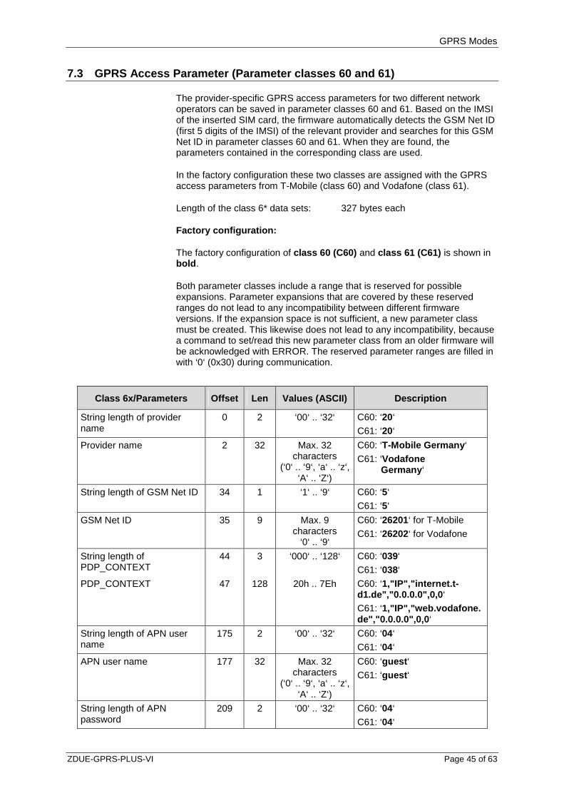
7.3 GPRS Access Parameter (Parameter classes 60 and 61)
The provider-specific GPRS access parameters for two different network operators can be saved in parameter classes 60 and 61. Based on the IMSI of the inserted SIM card, the firmware automatically detects the GSM Net ID (first 5 digits of the IMSI) of the relevant provider and searches for this GSM Net ID in parameter classes 60 and 61. When they are found, the parameters contained in the corresponding class are used.
In the factory configuration these two classes are assigned with the GPRS access parameters from T-Mobile (class 60) and Vodafone (class 61).
Length of the class 6* data sets: 327 bytes each
Factory configuration:
The factory configuration of class 60 (C60) and class 61 (C61) is shown in bold .
Both parameter classes include a range that is reserved for possible expansions. Parameter expansions that are covered by these reserved ranges do not lead to any incompatibility between different firmware versions. If the expansion space is not sufficient, a new parameter class must be created. This likewise does not lead to any incompatibility, because a command to set/read this new parameter class from an older firmware will be acknowledged with ERROR. The reserved parameter ranges are filled in with ‘0‘ (0x30) during communication.
Class 6x/Parameters Offset Len Values (ASCII) Description
String length of provider name
0 2 ‘00‘ .. ‘32‘ C60: ‘20‘
C61: ‘20‘
Provider name 2 32 Max. 32 characters
(‘0‘ .. ‘9‘, ‘a‘ .. ‘z‘, ‘A‘ .. ‘Z‘)
C60: ‘T-Mobile Germany ‘
C61: ‘Vodafone Germany ‘
String length of GSM Net ID 34 1 ‘1‘ .. ‘9‘ C60: ‘5‘
C61: ‘5‘
GSM Net ID 35 9 Max. 9 characters
‘0‘ .. ‘9‘
C60: ‘26201‘ for T-Mobile C61: ‘26202‘ for Vodafone
String length of PDP_CONTEXT
44 3 ‘000‘ .. ‘128‘ C60: ‘039‘ C61: ‘038‘
PDP_CONTEXT 47 128 20h .. 7Eh
C60: ‘1,"IP","internet.t-d1.de","0.0.0.0",0,0 ‘
C61: ‘1,"IP","web.vodafone. de","0.0.0.0",0,0 ‘
String length of APN user name
175 2 ‘00‘ .. ‘32‘ C60: ‘04‘
C61: ‘04‘
APN user name 177 32 Max. 32 characters
(‘0‘ .. ‘9‘, ‘a‘ .. ‘z‘, ‘A‘ .. ‘Z‘)
C60: ‘guest ‘
C61: ‘guest ‘
String length of APN password
209 2 ‘00‘ .. ‘32‘ C60: ‘04‘
C61: ‘04‘

GPRS Modes
Page 46 of 63 ZDUE-GPRS-PLUS-VI
Class 6x/Parameters Offset Len Values (ASCII) Description
APN password 211 32 Max. 32 characters
(‘0‘ .. ‘9‘, ‘a‘ .. ‘z‘, ‘A‘ .. ‘Z‘)
C60: ‘guest ‘
C61: ‘guest ‘
String length of dial-in string 243 2 ‘00‘ .. ‘32‘ C60: ‘08‘
C61: ‘08‘
Dial-in string 245 32 Max. 32 characters
(‘0‘ .. ‘9‘, ‘a‘ .. ‘z‘, ‘A‘ .. ‘Z‘)
C60: ‘*99***1#‘ C61: ‘*99***1#‘
DNS1 277 15 ‘0‘ .. ‘9‘ and ‘.‘ C60: ‘193.254.160.001‘
C61: ‘139.007.030.125‘
DNS2 292 15 ‘0‘ .. ‘9‘ and ‘.‘ C60: ‘194.025.002.131‘
C61: ‘139.007.030.126‘
Reserve for parameter expansions
307 20 TBD TBD
GPRS Modes
ZDUE-GPRS-PLUS-VI Page 47 of 63
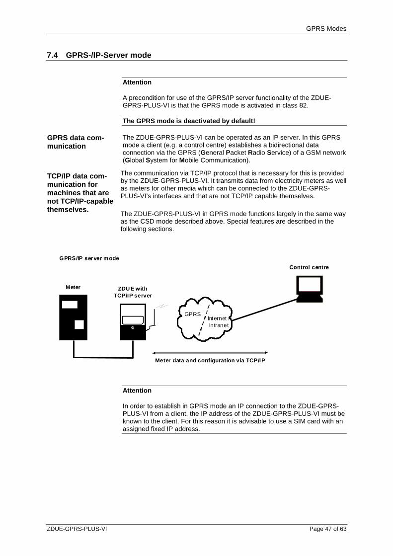
7.4 GPRS-/IP-Server mode
Attention
A precondition for use of the GPRS/IP server functionality of the ZDUE-GPRS-PLUS-VI is that the GPRS mode is activated in class 82.
The GPRS mode is deactivated by default!
GPRS data com-munication
The ZDUE-GPRS-PLUS-VI can be operated as an IP server. In this GPRS mode a client (e.g. a control centre) establishes a bidirectional data connection via the GPRS (General Packet Radio Service) of a GSM network (Global System for Mobile Communication).
TCP/IP data com-munication for machines that are not TCP/IP-capable themselves.
The communication via TCP/IP protocol that is necessary for this is provided by the ZDUE-GPRS-PLUS-VI. It transmits data from electricity meters as well as meters for other media which can be connected to the ZDUE-GPRS-PLUS-VI’s interfaces and that are not TCP/IP capable themselves. The ZDUE-GPRS-PLUS-VI in GPRS mode functions largely in the same way as the CSD mode described above. Special features are described in the following sections.
GPRS
Control centre
Meter data and configuration via TCP/IP
Internet /Intranet
GPRS/IP server mode
ZDU E withTCP/IP server
Meter
Attention
In order to establish in GPRS mode an IP connection to the ZDUE-GPRS-PLUS-VI from a client, the IP address of the ZDUE-GPRS-PLUS-VI must be known to the client. For this reason it is advisable to use a SIM card with an assigned fixed IP address.

GPRS Modes
Page 48 of 63 ZDUE-GPRS-PLUS-VI
Dialling into the GPRS network
The connection to the GPRS provider is established automatically after the device is restarted, so long as the GPRS mode is activated in class 82.
To successfully establish the connection, the GPRS access data must be configured in the parameter classes 60 and 61:
Provider (selection of the GPRS network operator, e.g. T-D1, Vodafone)
PDP_Context (access parameters of the GPRS network operator)
USER (login name in the GPRS network)
PASSWORD (login password in the GPRS network)
Dial-in string (not used)
DNS1 (primary Domain Name Server in the GPRS network; optional)
DNS2 (secondary Domain Name Server in the GPRS network; optional)
In addition, the timing behaviour in the event of problems with the GPRS dial-in can be set via class 82.
Attention
Please note that data packets are exchanged even when a connection is (re-) established, when an attempt to connect to a remote station is made (e.g. server is switched off, wrong destination address, etc.), and to maintain a connection. Please especially note this when using networks which are subject to charges!
Setting up the IP server
Like dialling-in to the GPRS network, the IP server is set up automatically when GPRS mode is activated. The following characteristics of the IP server must be defined in class 82:
GPRS function (must be set in order for the device to work in GPRS mode)
Server port 1 (port at which the server waits for incoming IP connection requests; server port 2 is not considered)
Optionally the access authorisation can be limited in class 82:
Check source IP address of the client (the source IP address of a connection request is evaluated)
Source IP addresses 1 to 5 (valid source addresses of a connection request)
Check source port of the client (the source port of a connection request is evaluated)
Source ports 1 to 5 (valid source ports of a connection request)
GSM data communication
As a substitute (e.g. in case of failure of the GPRS connection) the ZDUE-GPRS-PLUS-VI in GPRS mode can accept also CSD calls (CircuitSwitchedData calls) from a remote station, thus providing communication via the GSM network.
In this case the behaviour for data transmission to any other desired modem in the GSM or fixed network is the same as described above.
GPRS Modes
ZDUE-GPRS-PLUS-VI Page 49 of 63
Changeover between GPRS and GSM operation
Manual changeover between GPRS operation and GSM operation is not necessary. GSM data calls (CSD) are accepted if
GPRS mode is deactivated, but the device is checked into the GSM network
the device is logged into the GPRS network
the IP server is set up, but there is no active IP connection
CSD calls are rejected if
a CSD connection already exists
an active IP connection has been established (independent of the data flow)
In order to accept the GSM data call the GPRS connection is terminated. When the GSM data call is complete, the GSM data call is restarted, the GPRS connection is re-established and the IP server is set up again
Remote configuration via GSM data connection
Remote configuration of the ZDUE-GPRS-PLUS-VI in GPRS mode is possible via GPRS as well as via GSM connection.
Attention
For time-critical applications there can be limitations for GPRS transmissions. Although the transmission in the GPRS network generally only lasts a few 100s of milliseconds, due to the packet-switched infrastructure of the GPRS network individual data packets may take quite a bit longer to arrive, i.e. up to several seconds. This can also lead to problems when time-critical control centre software is used if it expects replies within a certain time after commands are sent out.
7.4.1 Access protection
The ZDUE-GPRS-PLUS-VI in GPRS mode accepts exactly one active IP connection at a time. If there is already an active IP connection to the ZDUE-GPRS-PLUS-VI, further connection requests are rejected by the device.
Furthermore, the ZDUE-GPRS-PLUS-VI offers the possibility of regulating the group of authorised clients. Two different mechanisms can be activated independently of each other for this purpose:

GPRS Modes
Page 50 of 63 ZDUE-GPRS-PLUS-VI
Source IP check In parameter class 82, up to five IP addresses can be stored for the source IP check. Only IP connection requests that have one of these IP addresses as the source address will be accepted. If no match is determined for the address, the ZDUE-GPRS-PLUS-VI rejects the connection request.
Precondition: The source IP check in parameter class 82 must be activated; by default no IP check is performed.
Source port check In parameter class 82, up to five port numbers can be stored for the source port check. Only IP connection requests that have one of these port numbers as the as the source port number will be accepted. If no match is determined for the port, the ZDUE-GPRS-PLUS-VI rejects the connection request.
Precondition: The source port check in parameter class 82 must be activated; by default no port check is performed.
7.4.2 Function indicators
In the GPRS mode, the function indicators behave the same as in the CSD mode; A existingTCP/IP connection is not indicated.
7.4.3 Parameters
The following table provides an overview of the parameter classes contained in the ZDUE-GPRS-PLUS-VI additionally for GPRS mode.These classes are assigned to numbers, which must also be specified in parameterisation commands.
Class
Permitted access types (R=Read/W=Write)
Provider classes 60, 61 R/W
GPRS operating parameters 82 R/W
Parameters can only be written by writing a complete class (i.e. an offset and length must also be specified with ‘0000‘).

GPRS Modes
ZDUE-GPRS-PLUS-VI Page 51 of 63
Parameter class 82
Length of the class 82 data set: 208 bytes
Factory configuration: The factory configuration of class 82 is shown in bold .
This class describes the GPRS parameters of the ZDUE-GPRS-PLUS-VI. The class is defined as an open class, i.e. data sets that are longer than what is defined here are accepted. The non-specified values are ignored in evaluation by the device. When the parameters are read only the specified values are output.
Class 82/Parameters Offset Len Values (ASCII) Description
GPRS function is active 0 1 ‘0‘ or ‘1‘ ‘0‘: GPRS function is switched off ‘1‘: GPRS function is switched on Def.: ‘0‘
Server port 1 at which the device receives data
1 5 5 characters ‘0‘ .. ‘9‘
Port number at which the server ‘listens‘ Def.: ‘26864‘
Server port 2 at which the device receives data
6 5 5 characters ‘0‘ .. ‘9‘
Port number at which the server ‘listens‘ Def.: ‘00000‘4
Check source IP of the communication
11 1 ‘0‘ or ‘1‘ ‘0‘: IP checking is switched off ‘1‘: IP checking is switched on Def.: ‘0‘
Check source port of the communication
12 1 ‘0‘ or ‘1‘ ‘0‘: Port checking is switched off ‘1‘: Port checking is switched on Def.: ‘0‘
Source IP no. 1 for permitted access
13 15 ‘0‘ .. ‘9‘ and ‘.‘ Source IP of a potential communication partner Def.: ‘000.000.000.000‘5
Source port no. 1 for permitted access
28 5 5 characters ‘0‘ .. ‘9‘
Source port of a potential communication partner Def.: ‘00000‘6
Source IP no. 2 for permitted access
33 15 ‘0‘ .. ‘9‘ and ‘.‘ Source IP of a potential communication partner Def.: ‘000.000.000.000‘
Source port no. 2 for permitted access
48 5 5 characters ‘0‘ .. ‘9‘
Source port of a potential communication partner Def.: ‘00000‘
4 If a '00000' is defined for the server port, the server function is not activated. The second port number is not supported at present. It should be classified as a reserve. 5 If checking of the source IP is activated, the source IP of the external communication partner must match completely. 6 If checking of the source port is activated, the source port of the external communication partner must match completely.

GPRS Modes
Page 52 of 63 ZDUE-GPRS-PLUS-VI
Class 82/Parameters Offset Len Values (ASCII) Description
Source IP no. 3 for permitted access
53 15 ‘0‘ .. ‘9‘ and ‘.‘ Source IP of a potential communication partner Def.: ‘000.000.000.000‘
Source port no. 3 for permitted access
68 5 5 characters ‘0‘ .. ‘9‘
Source port of a potential communication partner Def.: ‘00000‘
Source IP no. 4 for permitted access
73 15 ‘0‘ .. ‘9‘ and ‘.‘ Source IP of a potential communication partner Def.: ‘000.000.000.000‘
Source port no. 4 for permitted access
88 5 5 characters ‘0‘ .. ‘9‘
Source port of a potential communication partner Def.: ‘00000‘
Source IP no. 5 for permitted access
93 15 ‘0‘ .. ‘9‘ and ‘.‘ Source IP of a potential communication partner Def.: ‘000.000.000.000‘
Source port no. 5 for permitted access
108 5 5 characters ‘0‘ .. ‘9‘
Source port of a potential communication partner Def.: ‘00000‘
Connection test via ping activated
113 1 ‘0‘ or ‘1‘ ‘0‘: Ping function is switched off ‘1‘: Ping function is switched on7 Def.: ‘0‘
Time interval for ping test in minutes
114 4 ‘0000‘ to ‘9999‘ A cyclical ping is performed on one or more URLs in the specified cycle. Def.: ‘0030‘
IP address 1 for ping test 118 15 ‘0‘ .. ‘9‘ and ‘.‘ Destination IP of a potential communication partner for a ping8 e.g.: ‘062.109.255.003‘ Def.: ‘000.000.000.000‘
IP address 2 for ping test 133 15 ‘0‘ .. ‘9‘ and ‘.‘ Destination IP of a potential communication partner for a ping e.g.: ‘062.109.255.003‘ Def.: ‘000.000.000.000‘
IP address 3 for ping test 148 15 ‘0‘ .. ‘9‘ and ‘.‘ Destination IP of a potential communication partner for a ping e.g.: ‘062.109.255.003‘ Def.: ‘000.000.000.000‘
IP address 4 for ping test 163 15 ‘0‘ .. ‘9‘ and ‘.‘ Destination IP of a potential communication partner for a ping e.g.: ‘062.109.255.003‘ Def.: ‘000.000.000.000‘
7 No ping monitoring function is implemented at present 8 No ping monitoring function is implemented at present
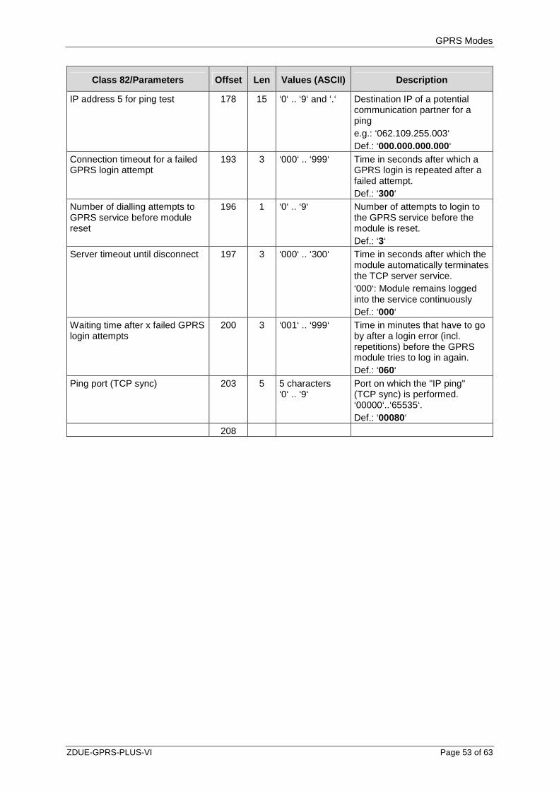
GPRS Modes
ZDUE-GPRS-PLUS-VI Page 53 of 63
Class 82/Parameters Offset Len Values (ASCII) Description
IP address 5 for ping test 178 15 ‘0‘ .. ‘9‘ and ‘.‘ Destination IP of a potential communication partner for a ping e.g.: ‘062.109.255.003‘ Def.: ‘000.000.000.000‘
Connection timeout for a failed GPRS login attempt
193 3 ‘000‘ .. ‘999‘ Time in seconds after which a GPRS login is repeated after a failed attempt. Def.: ‘300‘
Number of dialling attempts to GPRS service before module reset
196 1 ‘0‘ .. ‘9‘ Number of attempts to login to the GPRS service before the module is reset. Def.: ‘3‘
Server timeout until disconnect 197 3 ‘000‘ .. ‘300‘ Time in seconds after which the module automatically terminates the TCP server service. ‘000‘: Module remains logged into the service continuously Def.: ‘000‘
Waiting time after x failed GPRS login attempts
200 3 ‘001‘ .. ‘999‘ Time in minutes that have to go by after a login error (incl. repetitions) before the GPRS module tries to log in again. Def.: ‘060‘
Ping port (TCP sync) 203 5 5 characters ‘0‘ .. ‘9‘
Port on which the "IP ping" (TCP sync) is performed. ‘00000‘..‘65535‘. Def.: ‘00080‘
208

GPRS Modes
Page 54 of 63 ZDUE-GPRS-PLUS-VI
7.4.4 Register data set in GPRS mode
General
The register data set in GPRS mode is the same as in CSD mode. When GPRS mode is activated, the IP address currently assigned to the device is output in register 129-72:23.7.0 (see also Section 6.4)
Example: Accounting data of ZDUE-GPRS-PLUS-VI
1-1:F.F(00000005) Error status
1-1:0.0.0(12345678) Power supply company identification
1-1:0.2.0( 4.016) Firmware version of the ZDUE
1-1:0.9.1(135224) Time (hhmmss)
1-1:0.9.2(110326) Date (yymmdd)
1-1:C.91.0(Revision 01.002) Firmware version of GSM module
129-72:23.7.0(29.9.18.87) [own IP address]
!
T
Format of the error status
The error status format is described in Section 6.4.2.
7.4.5 Communication commands according to DIN EN 62 056-21
The ZDUE-GPRS-PLUS-VI in GPRS mode supports the same communication commands as in CSD mode. There are also GPRS-specific commands; these are listed in the following.
Parameterisation commands
The three parameter classes 60, 61 and 82 additionally contained in the ZDUE-GPRS-PLUS-VI for GPRS mode are configured according to the parameterisation of the ZDUE-GPRS-PLUS-VI standard classes (see 6.5.3) and saved to non-volatile memory in the device using the parameter transfer command (see 6.5.4).

GPRS Modes
ZDUE-GPRS-PLUS-VI Page 55 of 63
Service commands
R3 commands:
1. Reading GPRS operating parameters:
Command format: <SOH>R3<STX>S96(12)<ETX><BCC>
Reply format: <STX>S96(12)(LocalIP)(NetMask)(Gateway)(DNS1)(DNS2) <ETX><BCC>
The parameters have the following meaning here:
LocalIP IP address currently assigned to the device. If the device currently has no address assigned to it, "000.000.000.000" is output.
NetMask This value remains empty
Gateway This value remains empty
DNS1 Current DNS1
DNS2 Current DNS2
Example (reply): <STX>S96(12)(172.20.233.0)()()(139.007.030.125)(139.007.030.126)<ETX><BCC>
This command is also permitted via the GSM interface.
When GPRS mode is deactivated this command is unknown and will be rejected with an error message:
Reply in case of error: <ETX>(ERROR01)<ETX><BCC>

GPRS Modes
Page 56 of 63 ZDUE-GPRS-PLUS-VI
7.5 GPRS-IP-Telemetry mode
Attention
To use the GPRS-/IP-Telemetry funktion of ZDUE-GPRS-PLUS-VI it is required, that the GPRS mode in parameter class 70 is activated. This setting takes priority over the GPRS-/IP server mode (parameter class 82)
By default the GPRS-IP-Telemetry mode is NOT activa ted.
In GPRS-IP-Telemetry mode, as soon as a connection to internet or intranet via GPRS is available, the ZDUE-GPRS-PLUS-VI establishes an IP telemetry connection in accordance to E DIN 43863-4 to a selected IP-T master. Therefore a corresponding account must be configured at the IP-T master (e.g. Dr. Neuhaus TAINY SwitchingCenter V3). The login is made by using login name and password.
GPRS
Control station
Meter data and configuration via IP-Telemetry connection
Internet /Intranet
GPRS-IP-Telemetry mode
ZDUE asIP-Telemetry-Client
Meter
IPT-Master, e.g. TAINY SwitchingCenter
The control station is also connected to the IP-Telemetry master. All the communication between control station and ZDUE-GPRS-PLUS-VI is transferred via the IP-Telemetry master.
The ZDUE-GPRS-PLUS-VI provides the opportunity to define a secondary IP-Telemetry master. If the connection to an IP-Telemetry master cannot be established (e.g. master not reachable) or is refused by the master (e.g. invalid user name/password combination), the other master can be used as an alternative by the ZDUE-GPRS-PLUS-VI.
The primary and secondary IP-Telemetry master may also reject a login attempt for load balancing reasons, provided this service is activated within the respective TAINY SwitchingCenter. In this case the rejecting IP-Telemetry master reroutes the ZDUE-GPRS-PLUS-VI by sending the IP address of an alternative IP-Telemetry master to the device. This IP address is independent from the server settings of the ZDUE-GPRS-PLUS-VI.
7.5.1 Function indicators
In the GPRS-IP-Telemetry mode, the function indicators behave the same as in the CSD mode; An existing IP-Telemetry connection is not indicated.
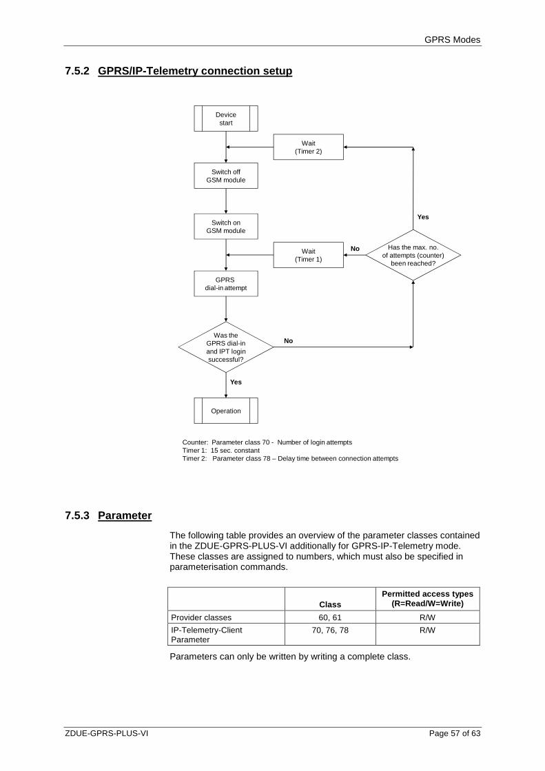
GPRS Modes
ZDUE-GPRS-PLUS-VI Page 57 of 63
7.5.2 GPRS/IP-Telemetry connection setup
Devicestart
Switch offGSM module
Switch onGSM module
GPRS dial-in attempt
Was theGPRS dial-inand IPT loginsuccessful?
Operation
Wait(Timer 2)
Wait(Timer 1)
Has the max. no.of attempts (counter)
been reached?
Yes
No
No
Yes
Counter: Parameter class 70 - Number of login attemptsTimer 1: 15 sec. constantTimer 2: Parameter class 78 – Delay time between connection attempts
7.5.3 Parameter
The following table provides an overview of the parameter classes contained in the ZDUE-GPRS-PLUS-VI additionally for GPRS-IP-Telemetry mode. These classes are assigned to numbers, which must also be specified in parameterisation commands.
Class
Permitted access types (R=Read/W=Write)
Provider classes 60, 61 R/W
IP-Telemetry-Client Parameter
70, 76, 78 R/W
Parameters can only be written by writing a complete class.
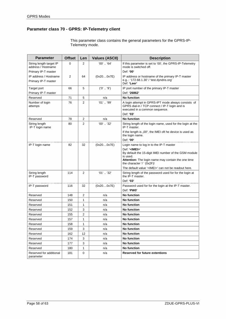
GPRS Modes
Page 58 of 63 ZDUE-GPRS-PLUS-VI
Parameter class 70 - GPRS: IP-Telemetry client
This parameter class contains the general parameters for the GPRS-IP-Telemetry mode.
Parameter Offset Len Values (ASCII) Description String length target IP address / Hostname
Primary IP-T master
0 2 ‘00‘ .. ‘64‘ If this parameter is set to ‘00‘, the GPRS-IP-Telemetry mode is switched off.
Def: ‘00‘
IP address / Hostname
Primary IP-T master
2 64 (0x20....0x7E) IP address or hostname of the primary IP-T master e.g..: ‘172.68.1.30’ / ‘test.dyndns.org’ Def: ‘Leer‘
Target port
Primary IP-T master
66 5 (‘0‘ .. ‘9’) IP port number of the primary IP-T master
Def: ‘26862’
Reserved 71 5 n/a No function
Number of login attemps
76 2 ‘01‘ .. ‘99‘ A login attempt in GPRS-IPT mode always consists of GPRS dial-in / TCP connect / IP-T login and is executed in a common sequence.
Def: ‘03‘
Reserved 78 2 n/a No function
String length IP-T login name
80 2 ‘00‘ .. ‘32‘ String length of the login name, used for the login at the IP-T master.
If the length is „00“, the IMEI oft he device is used as the login name.
Def: ‘00‘
IP-T login name
82 32 (0x20....0x7E) Login name to log in to the IP-T master
Def: ‘<IMEI>’ By default the 15-digit IMEI number of the GSM module is used. Attention: The login name may contain the one time the character ‘/ ‘ (0x2F)!
The default value ‘<IMEI>’ can not be readout here.
String length IP-T password
114 2 ‘01‘ .. ‘32‘ String length of the password used for for the login at the IP-T master.
Def: ‘03‘
IP-T password
116 32 (0x20....0x7E) Password used for for the login at the IP-T master.
Def: ‘PW0’
Reserved 148 2 n/a No function
Reserved 150 1 n/a No function
Reserved 151 1 n/a No function
Reserved 152 3 n/a No function
Reserved 155 2 n/a No function
Reserved 157 1 n/a No function
Reserved 158 1 n/a No function
Reserved 159 3 n/a No function
Reserved 162 12 n/a No function
Reserved 174 3 n/a No function
Reserved 177 3 n/a No function
Reserved 180 1 n/a No function
Reserved for additional parameter
181 0 n/a Reserved for future extentions
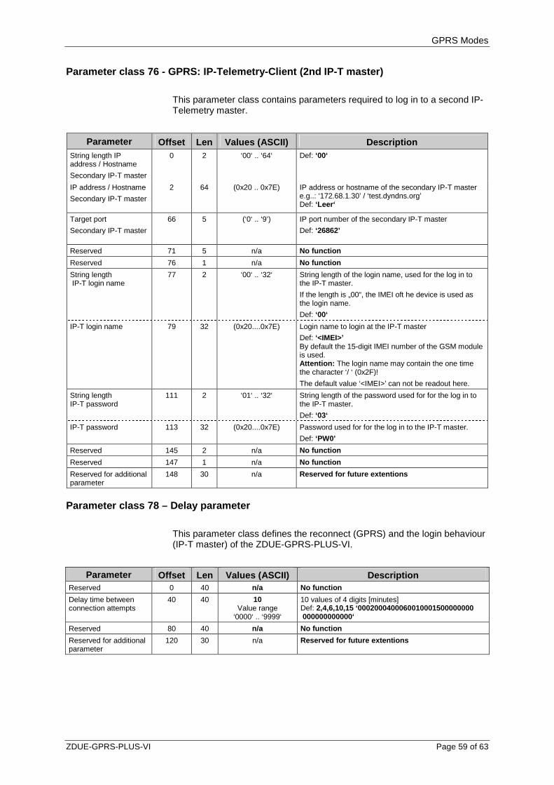
GPRS Modes
ZDUE-GPRS-PLUS-VI Page 59 of 63
Parameter class 76 - GPRS: IP-Telemetry-Client (2nd IP-T master)
This parameter class contains parameters required to log in to a second IP-Telemetry master.
Parameter Offset Len Values (ASCII) Description
String length IP address / Hostname
Secondary IP-T master
0 2 ‘00‘ .. ‘64‘ Def: ‘00‘
IP address / Hostname
Secondary IP-T master
2 64 (0x20 .. 0x7E) IP address or hostname of the secondary IP-T master e.g..: ‘172.68.1.30’ / ‘test.dyndns.org’ Def: ‘Leer‘
Target port
Secondary IP-T master
66 5 (‘0‘ .. ‘9’) IP port number of the secondary IP-T master
Def: ‘26862’
Reserved 71 5 n/a No function
Reserved 76 1 n/a No function
String length IP-T login name
77 2 ‘00‘ .. ‘32‘ String length of the login name, used for the log in to the IP-T master.
If the length is „00“, the IMEI oft he device is used as the login name.
Def: ‘00‘
IP-T login name
79 32 (0x20....0x7E) Login name to login at the IP-T master
Def: ‘<IMEI>’ By default the 15-digit IMEI number of the GSM module is used. Attention: The login name may contain the one time the character ‘/ ‘ (0x2F)!
The default value ‘<IMEI>’ can not be readout here.
String length IP-T password
111 2 ‘01‘ .. ‘32‘ String length of the password used for for the log in to the IP-T master.
Def: ‘03‘
IP-T password
113 32 (0x20....0x7E) Password used for for the log in to the IP-T master.
Def: ‘PW0’
Reserved 145 2 n/a No function
Reserved 147 1 n/a No function
Reserved for additional parameter
148 30 n/a Reserved for future extentions
Parameter class 78 – Delay parameter
This parameter class defines the reconnect (GPRS) and the login behaviour (IP-T master) of the ZDUE-GPRS-PLUS-VI.
Parameter Offset Len Values (ASCII) Description
Reserved 0 40 n/a No function
Delay time between connection attempts
40 40 10 Value range
‘0000‘ .. ‘9999‘
10 values of 4 digits [minutes] Def: 2,4,6,10,15 ‘0002000400060010001500000000 000000000000‘
Reserved 80 40 n/a No function
Reserved for additional parameter
120 30 n/a Reserved for future extentions

GPRS Modes
Page 60 of 63 ZDUE-GPRS-PLUS-VI
7.5.4 Register data set in GPRS mode
General
As being described in Section 7.4.4.
Format of the error status
The error status format is described in Section 6.4.2.
7.5.5 Communication commands according to DIN EN 62 056-21
The ZDUE-GPRS-PLUS-VI in GPRS-IP-Telemetry mode supports the same communication commands as in CSD mode. There are also GPRS-specific commands; these are listed in the following.
Parameterisation commands
The three parameter classes 70, 76 and 78 additionally contained in the ZDUE-GPRS-PLUS-VI for GPRS-IP-Telemetry mode are configured according to the parameterisation of the ZDUE-GPRS-PLUS-VI standard classes (see 6.5.3) and saved to non-volatile memory in the device using the parameter transfer command (see 6.5.4).
Service commands
R3 commands: 1. Reading GPRS operating parameters
Command format: <SOH>R3<STX>S96(12)<ETX><BCC>
Reply format: <STX>S96(12)(LocalIP)(NetMask)(Gateway)(DNS1)(DNS2) <ETX><BCC>
The parameters have the following meaning here:
LocalIP IP address currently assigned to the device. If the device currently has no address assigned to it, "000.000.000.000" is output.
NetMask This value remains empty
Gateway This value remains empty
DNS1 Current DNS1
DNS2 Current DNS2

GPRS Modes
ZDUE-GPRS-PLUS-VI Page 61 of 63
Example (reply): <STX>S96(12)(172.20.233.0)()()(139.007.030.125)(139.007.030.126)<ETX><BCC>
This command is also permitted via the GSM interface.
When GPRS mode is deactivated this command is unknown and will be rejected with an error message:
Reply in case of error: <ETX>(ERROR01)<ETX><BCC
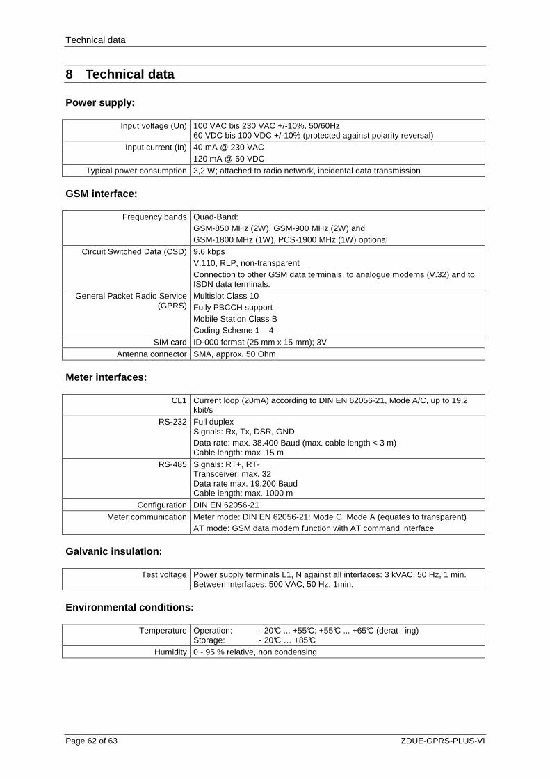
Technical data
Page 62 of 63 ZDUE-GPRS-PLUS-VI
8 Technical data
Power supply:
Input voltage (Un) 100 VAC bis 230 VAC +/-10%, 50/60Hz 60 VDC bis 100 VDC +/-10% (protected against polarity reversal)
Input current (In) 40 mA @ 230 VAC 120 mA @ 60 VDC
Typical power consumption 3,2 W; attached to radio network, incidental data transmission
GSM interface:
Frequency bands Quad-Band: GSM-850 MHz (2W), GSM-900 MHz (2W) and GSM-1800 MHz (1W), PCS-1900 MHz (1W) optional
Circuit Switched Data (CSD) 9.6 kbps V.110, RLP, non-transparent Connection to other GSM data terminals, to analogue modems (V.32) and to ISDN data terminals.
General Packet Radio Service (GPRS)
Multislot Class 10 Fully PBCCH support Mobile Station Class B Coding Scheme 1 – 4
SIM card ID-000 format (25 mm x 15 mm); 3V Antenna connector SMA, approx. 50 Ohm
Meter interfaces:
CL1 Current loop (20mA) according to DIN EN 62056-21, Mode A/C, up to 19,2 kbit/s
RS-232 Full duplex Signals: Rx, Tx, DSR, GND Data rate: max. 38.400 Baud (max. cable length < 3 m) Cable length: max. 15 m
RS-485 Signals: RT+, RT- Transceiver: max. 32 Data rate max. 19.200 Baud Cable length: max. 1000 m
Configuration DIN EN 62056-21 Meter communication Meter mode: DIN EN 62056-21: Mode C, Mode A (equates to transparent)
AT mode: GSM data modem function with AT command interface
Galvanic insulation:
Test voltage Power supply terminals L1, N against all interfaces: 3 kVAC, 50 Hz, 1 min. Between interfaces: 500 VAC, 50 Hz, 1min.
Environmental conditions:
Temperature Operation: - 20°C ... +55°C; +55°C ... +65°C (derat ing) Storage: - 20°C … +85°C
Humidity 0 - 95 % relative, non condensing
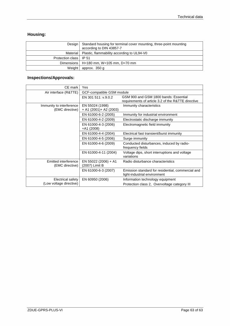
Technical data
ZDUE-GPRS-PLUS-VI Page 63 of 63
Housing:
Design Standard housing for terminal cover mounting, three-point mounting according to DIN 43857-7
Material Plastic, flammability according to UL94-V0 Protection class IP 51
Dimensions H=180 mm, W=105 mm, D=70 mm Weight approx. 350 g
Inspections/Approvals:
CE mark Yes
GCF-compatible GSM module Air interface (R&TTE) EN 301 511: v.9.0.2 GSM 900 and GSM 1800 bands: Essential
requirements of article 3.2 of the R&TTE directive EN 55024 (1998) + A1 (2001)+ A2 (2003)
Immunity characteristics
EN 61000-6-2 (2005) Immunity for industrial environment EN 61000-4-2 (2009) Electrostatic discharge immunity EN 61000-4-3 (2006) +A1 (2008)
Electromagnetic field immunity
EN 61000-4-4 (2004) Electrical fast transient/burst immunity EN 61000-4-5 (2006) Surge immunity EN 61000-4-6 (2009) Conducted disturbances, induced by radio-
frequency fields
Immunity to interference (EMC directive)
EN 61000-4-11 (2004) Voltage dips, short interruptions and voltage variations
EN 55022 (2006) + A1 (2007) Limit B
Radio disturbance characteristics Emitted interference (EMC directive)
EN 61000-6-3 (2007) Emission standard for residential, commercial and light-industrial environment
Electrical safety (Low voltage directive)
EN 60950 (2006)
Information technology equipment Protection class 2, Overvoltage category III