zakres programowania rejestratora kd7 - lumel.com.pl do pobrania/kd8/kd8... · kd connect program...
TRANSCRIPT
SCREEN RECORDER
KD8
USER'S MANUAL
2
CONTENTS
1. INTRODUCTION…………………………………………………………….………... 4 1.1 Recorder applications ..................................................................................…... 4 1.2 Recorder features ......................................................................................……... 4 2. GENERAL INFORMATION.............................................................................…. 5 2.1 Warning and information signs ..................................................................……... 5 2.2 Safety of service ...................................................................................…..…….. 5 2.2.1 Remarks concerning the recorder installation...........................................…....… 5 2.2.2 Precautions in the scope of ESD protection……………………………………..…. 6 3. RECORDER PREPARATION TO WORK......................................................….. 7 3.1 Unpacking ...............................................................................................…….…. 7 3.2 Installation in a panel ……................................................................................… 8 3.3 Operating conditions of the recorder…….........................................................… 8 4. RECORDER CONSTRUCTION…….................................................................... 9 4.1 LCD screen with touch panel …….................................................................….. 9 4.2 CompactFlash memory card, USB interface, LED diode................................….. 10 4.3 Terminal plate ..............................................................................................……. 11 4.3.1 Connection of analog signals…….. .................. .............................................…. 12 4.3.1.1 Programmable measuring inputs AI 1..6 .................................................…..... 12 4.3.1.2 Alarms AL 1...12 and binary inputs BI 1..8 ..........................................… 13 4.3.1.3 Interfaces RS485 Modbus Slave)........................................................................ 13 4.3.2 Recorder supply (a.c. or d.c.) ....................................................................…...… 14 5. GRAPHICAL SIGNS ON THE RECORDER SCREEN ……….......................…. 14 5.1 Status bar ............................................................................................................ 14 5.2 Measuring views…............................................................................................… 14 5.3 Service menu ....................................................................................................... 15 5.4 Information messages. …. .................................................................................. 15 5.5 Dialogues.............................................................................................................. 16 6. STARTING THE RECORDER..........................................................................… 16 6.1 Context menu …………………………………………………………………............ 17 6.2 Entry into the recorder parameter configuration , “KD8 control panel “ windows 19 7. CONFIGURING THE RECORDER................................................………….…… 20 7.1 General settings ........................................................................................……… 20 7.2 Modbus Slave configuration................................................................................. 21 7.3 KD8 security......................................................................................................... 22 7.4 System information .........................................................................................… 23 7.5 CF Card………………………………………………………………………………. 24 7.6 Configuration, visualization and archiving of the channel group…………………. 24 7.7 Analog and binary inputs ….. .............................................................................. 26 7.7.1 Programming analog inputs AL1…AL16 …………………………………………. 26 7.7.2 Alarm (A1 i A2) in analog input configuration…………..………………………….. 31 7.7.3 Binary input BI1..BI8 configuration ………………...........................................….. 35 7.7.4 Common parameters for binary inputs ………………….……….………………… 36 7.8 Programming of measuring groups ……………….……………………………… 36 7.8.1 Programming of group parameters………………………………………………. 36 7.8.2 Digital view of the channel group…………………………………………………….. 39 7.8.3 Linear chart of the channel group………………………………...…………………. 40 7.8.4 View of the channel group in the bargraph form………………….………………. 42 7.8.5 Analog view of the channel group......................…………………..…………….... 43 7.8.6 Statistic view of the channel group………………………………….………………. 44 7.8.7 Enabling/disabling the automatic screen switching.................................……… 45 7.9 Zoom scale function of the signal (measuring magnifier)………………….……. 46 7.10 Selection of the data file format (digital signature)…………………….………….. 47 7.11 Edition of the user’s name and access password for settings……………….…… 48
3
7.12 Event logs…………………………………………...……………………………………. 48 7.12.1 Review and service of event logs............................................................................ 49 7.12.2 Programming of event logs……………………………………………………………... 50 7.13 Edition of user’s messages……………………………………………………………... 51 7.14 Exit from the recorder configuration….…………………….………………….…….... 53 8. SELECTED ELEMENTS OF THE RECORDER CURRENT SERVICE.................. 54 8.1 CompactFlash memory card ……...................................................................……. 54 8.1.1 Information about the CF memory card................................................................... 54 8.1.2 Formatting the CF card.....................................................................................…… 54 8.1.3 Data storage on the CF card (card storage capacity)……………………..........…... 55 8.1.4 Visualization of the CF card state on the screen …….........................................… 57 8.1.5 Review and erasing of files from the CF card.......................................................... 57 8.1.6 Removal/replacement of the CF card, storage of archive data……………............ 58 8.2 Review of archived data ……………………………………………………………….. 59 8.3 Calibration of the touch screen ……………………………………………………….. 60 8.4 Updating of the recorder software …………………………………………………….. 61 8.5 Service of data stored on the CF card, visualization ………………………………... 62 9. PROGRAMS ON PC.........................................................................……............... 63 9.1 KD Connect program............................................................................................. 63 9.1.1 Installation of drivers for the KD8 recorder .........................................................… 63 9.1.2 Installation of the KD Connect program ............................................................…. 64 9.1.3 Program service....................................................................................................... 65 9.2 KD8 Setup program................................................................................................. 69 9.2.1 Installation................................................................................................................ 69 9.2.2 Program service………………………………………………………………………….. 69 9.3 KD Check program …….......................................................................................... 71 9.4 KD Archive program………………………………………………………………..……. 72 10. TECHNICAL DATA ................................................................................................ 73 11. ORDER CODES............................................................................……...........……. 76 12. MAINTENANCE AND GUARANTEE…………….……….………………………….. 77

4
1. INTRODUCTION
1.1 RECORDER APPLICATIONS
The KD8 screen recorder is applied as a data acquisition station in measuring and control systems.
It finds application to measure, visualize and supervise technical process parameters in various
industrial branches, e.g. pharmacy, food, chemical and papermaking industries.
It can be also used as an autonomous measuring and recording device.
The KD8 screen recorder is adapted to measure voltage, current, temperature, resistance changes
and other quantities converted into a signal or electrical parameter. All processes suitable for a
measuring system can be realized in this recorder: measurement of input signals and their
conversion, visualization and archiving of data, signalling and communication with the
environment.
Converted measuring data are stored in the internal memory and on the CompacFlash card.
1.2. RECORDER FEATURES
LCD TFT 5.7” colour screen, 320 x 240 pixels, with a touch panel for the recorder service,
Exchangeable CompactFlash external memory card with capacity from 16 MB up to 4 GB,
Communication interfaces: USB 1.1 Device, RS-485 Modbus Slave,
Measuring inputs for the direct connection of thermocouples, voltage, current and resistance,
Alarms, binary inputs,
Operator messages,
Digital signature for archived data, stored in text or binary format,
Linearization of sensor characteristics,
Programmable current, voltage and resistance inputs,
Copying of parameter setting between channels,
Programming of recorder parameters,
Programming of screens and choice of screen configurations,
Storage of data in the internal 6 MB buffer with data support (for before damage and after
damage states)
Determination of the set of data for the current exposition on the screen,
Choice of the time zone, automatic change of summer/winter time.
Note: The updating of the KD8 recorder software is accessible on the page:
http://www.lumel.com.pl

5
2. GENERAL INFORMATION
2.1 Warning and information signs
One or more of presented symbols can be used in the recorder.
Caution: one must pay attention to the description in the
recorder user’s manual.
Terminal of the protection lead
Earth terminal
Protection of sensitive electrostatic systems (ESD)
2.2 Safety of service
The KD8 recorder fulfils requirements related to safety of electrical measuring instruments for
automation, acc. to EN 61010-1 standard and requirements concerning the resistance against
interference occurring in industrial environment acc. to EN 61000-6-2 and EN 61000-6-4 standards.
The connection of supply, communication interfaces and measuring signals, and the use of
equipment inconsistent with the description included in the present user’s manual and standards as
above can cause serious weakening of the recorder protection against interference.
A switch or a circuit - breaker should be located near the device, easy accessible by the
operator and suitable marked.
2.2.1 Remarks concerning the recorder installation
Various sources of interference occurring in practice interact with the recorder in a continuous
or impulse way from the supply network side (as the result of the action of other devices) and also
overlap on the measured signal or auxiliary circuits of the recorder.
In particular, strong impulse interference is dangerous for the operation of devices since they
can cause sporadic erroneous measurement results or accidental operations of alarms, despite of the
use of suitable filters in the recorder. The level of this interference should be reduced to a value
lower than the resistance threshold of the recorder, first of all through a suitable installation of the
recorder in the object.
In this scope, it is recommended to observe following recommendations:
Do not supply recorders from networks near devices generating high impulse interference in the
supply network and do not use common grounding circuits with them,
Use network filters for the group of recorders servicing the same object,

6
Use metallic shields in the shape of tubes or braids to lead supplying wires (phase, zero), in
which one can also lead the earth conductor and eventually network wires supplying contacts
of alarm relays of the given recorder,
Lead individually connections of binary input circuits in shields as above, by means of twisted
wires,
Lead individually connections of communication interface circuits in shields as above and by
means of twisted wires,
Wires leading measuring signals for each measuring recorder channel should be twisted in pairs,
and for resistance sensors in 3-wire connection, twisted of wires of the same length, cross-
section and resistance, and led in shields as above. Wires leading measuring signals to the same
recorder can be led in the same shield ( if it is possible),
All shields should be earthed unilaterally near the recorder,
One must avoid a common earth conductor with other devices,
Apply the general principle, that wires (group of wires) leading different signals should be led in
the longest possible distance between them and crossings of such groups of wires made at a 90°
angle,
Set on the supply cable (near the recorder) a ferrite filter STAR-TEC 74271132 being in the
recorder accessory set.
One must remember that in the building installation a switch or a circuit-breaker should be
installed near the recorder, easy accessible by the operator and suitably marked.
Before removing the recorder housing, one must switch the supply off and disconnect measuring
circuits.
All operations concerning installation, commissioning as well as maintenance must be carried
out by qualified skilled personnel, and national regulations for the prevention of accidents must
be observed.
Protections ensuring the recorder safety may be less effective in case of an exploitation contrary
with producer's indications and principles of a good engineering practice.
2.2.2. Precautions in the scope of ESD protection
Semiconductor elements or packages used in the recorder design and marked with the sign as
above, can become damaged in result of electrostatic discharges (ESD).
In order to prevent this, one must observe following recommendations during service works.
Disassemble instruments only in the area protected against electrostatic discharges,
Use conductive materials to dissipate electrostatic charges in the working area,
Use only anti electrostatic packings to store electronic elements and packages,
Do not touch elements and packages with hands,
Do not keep materials susceptible to generate electrostatic charges in the working area.
CAUTION: Repairs and modifications in the recorder equipment
shoul should be carried out by authorized service workshops
or with the manufacturer.

7
3. RECORDER PREPARATION TO WORK
The recorder with accessories is delivered in packing fulfilling requirements of environment
protection regulations.
The recorder in the packing can be transported and stored in the temperature:
-20 ....+60ºC (-4 ...140ºF).
3.1 Unpacking
Taking the KD8 recorder out from the shipping packing
The data plate with the version code, factory number and supply parameters are placed on the
recorder housing. Before unpacking, check the conformity of the recorder version with the order.
Take recorder accessories out from the packing.
1. User’s manual (printed version or on a CD disk) 1 pc
2. 4 GB CF memory card 1 pc
3. Mounting brackets 4 pcs
4. Ferrite core 1 pc
5. USB cable 1.8m (shielded) 1 pc
6. Seal (KD8 housing– panel) 1 pc
7. Set of plugs 1)
1 set
8. CDR disk 2)
1 pc
3
LUMEL S.A.
5
1
6 7
4
8 9
10
2

8
9. Current test links
3 or 6 pcs
10. Keys 2 pcs
11. Guarantee card 1 pc
1) The set is accommodated to the ordered recorder version
2) Following documents are recorded on the CDR: user’s manual of the KD8 recorder,
KD CONNECT program for the communication with KD8 through the USB interface,
KD CHECK program to check the digital signature in archive files, USB drivers for the KD8
recorder and, according to the order version, KD8 SETUP and KD ARCHIVE programs with
user’s manuals to service these programs.
3.2 Installation in a panel
Put the seal from standard accessories on the housing (see section 3.1.). After mounting the
recorder into the panel, the seal protects the part behind the panel against the influence of risks
appearing from the frontal part of the panel, resulting from the IP65 protection degree.
The recorder is fixed to the panel by means of four screwed mounting brackets from the
recorder accessories (see section 3.1.).
Basic fixing and panel cut-out dimensions are presented above.
3.3. Operating conditions of the recorder
The recorder can work at ambient temperature: 0...+50ºC (32 ...122ºF) and max.75% of relative
air humidity without condensation.
9
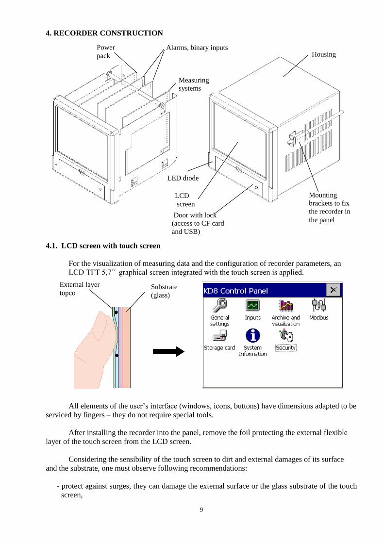
4. RECORDER CONSTRUCTION
4.1. LCD screen with touch screen
For the visualization of measuring data and the configuration of recorder parameters, an
LCD TFT 5,7” graphical screen integrated with the touch screen is applied.
All elements of the user’s interface (windows, icons, buttons) have dimensions adapted to be
serviced by fingers – they do not require special tools.
After installing the recorder into the panel, remove the foil protecting the external flexible
layer of the touch screen from the LCD screen.
Considering the sensibility of the touch screen to dirt and external damages of its surface
and the substrate, one must observe following recommendations:
- protect against surges, they can damage the external surface or the glass substrate of the touch
screen,
Housing
Mounting
brackets to fix
the recorder in
the panel
Power
pack
Measuring
systems
Alarms, binary inputs
LCD
screen
Door with lock
(access to CF card
and USB)
LED diode
Substrate
(glass)
External layer
topco
10
- protect against fluids, grease and aggressive chemical agents,
- touch only with fingers; do not use hard and sharp objects which can damage the flexible
surface of the touch screen,
- clean softly with a cotton cloth impregnated with a detergent destined to clean LCD monitors
(not containing alcohol, petrol or ammonia ) or by using water with soap,
- observe the given temperature range of the recorder operation.
Since there is the possibility of a memory effect symptom occurrence on screens of LCD type (after
a prolonged display of a constant figure), the blanking of the screen after a 15-minute continuous
work is set in the recorder as a standard, without touching the screen.
The renewed activation of the screen follows after touching it.
The blanking time can be changed or this function can be disabled (see section 7.1)
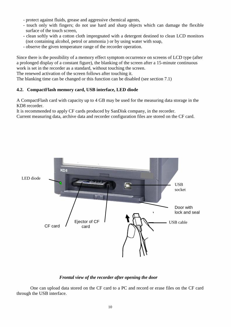
4.2. CompactFlash memory card, USB interface, LED diode
A CompactFlash card with capacity up to 4 GB may be used for the measuring data storage in the
KD8 recorder.
It is recommended to apply CF cards produced by SanDisk company, in the recorder.
Current measuring data, archive data and recorder configuration files are stored on the CF card.
Frontal view of the recorder after opening the door
One can upload data stored on the CF card to a PC and record or erase files on the CF card
through the USB interface.
Door with lock and seal
CF card Ejector of CF card
USB
socket
USB cable
LED diode

11
To connect the computer to the recorder through USB socket, use delivered in standard
accessories, the shielded USB AM-BM cable of 1.8 m long or another similar one of 5 m long (the
USB bus operates correctly without amplification at the distance up to 5 m).
In order that the KD8 recorder was seen in a PC with MS Windows operating system and
serviced through USB, one must install drivers and the KD Connect program from the delivered
CDR being in the recorder accessories (for description and program installation (see section 9.1 ) .
The LED diode placed on the left side of the door signals the recorder operating conditions:
Green colour of the diode – the recorder is set working, normal operating conditions
Red colour of the diode – signals the storage of data on CompactFlash
memory card. In these operating conditions,
one must not take out the card from the seat
risk of loss of measuring data!
4.3 Terminal plate
Programmable, universal
measuring channels
Alarms, binary inputs
Link for
current Suplly a.c.or d.c. range (AI 1)
Temperature sensor
Link for
current
range (AI 6)
Interface RS485
12
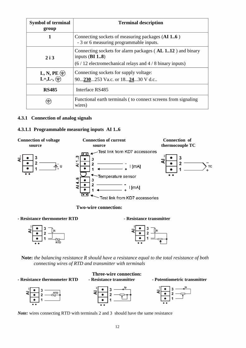
Symbol of terminal
group
Terminal description
1 Connecting sockets of measuring packages (AI 1..6 )
- 3 or 6 measuring programmable inputs.
2 i 3
Connecting sockets for alarm packages ( AL 1..12 ) and binary
inputs (BI 1..8)
(6 / 12 electromechanical relays and 4 / 8 binary inputs)
L, N, PE
L+,L-,
Connecting sockets for supply voltage:
90...230...253 Va.c. or 18...24...30 V d.c..
RS485 Interface RS485
Functional earth terminals ( to connect screens from signaling
wires)
4.3.1 Connection of analog signals
4.3.1.1 Programmable measuring inputs AI 1..6
Connection of voltage Connection of current Connection of
source source thermocouple TC
Two-wire connection:
- Resistance thermometer RTD - Resistance transmitter
Note: the balancing resistance R should have a resistance equal to the total resistance of both
connecting wires of RTD and transmitter with terminals
Three-wire connection: - Resistance thermometer RTD - Resistance transmitter - Potentiometric transmitter
Note: wires connecting RTD with terminals 2 and 3 should have the same resistance

13
Table 1, Thermocouples : Colour codes
Type of
thermo-
couple
Material
British
standard
BS
USA
standard
ASTM
German
standard
DIN
French
standard
NFE
International
standard
IEC 584-3
T Cu-CuNi + white - blue * blue
+ blue - red * blue
+ red - brown * brown
+ yellow - blue * blue
+ brown - white * blue
J Fe-CuNi + yellow - blue * black
+ white - red * black
+ red - blue * blue
+ yellow - grey * grey
+ black - white * blue
K NiCr-NiAl + brown - blue * red
+ yellow - red * yellow
+ red - green * green
+ yellow - purplish red * yellow
+ green - white * blue
R
S Pt-Rh13Pt Pt-Ph10Pt
+ white - blue * green
+ black - red * green
+ red - white * white
+ yellow - green * green
+ orange - white * blue
B Pt-Ph30Pt Use copper wires
+ grey - red * grey
+ red - grey * grey
Use copper wires
N NiCrSi- NiSi
+ orange - blue * orange
+ orange. - red * brown
+ orange - red * brown
+ orange - red * brown
+ pink - white * blue
E NiCr-CuNi + brown - blue * brown
+ brown - red * brown
+ red - grey * grey
+ yellow - purple * purple
+ brown - white * blue
4.3.1.2 Alarms AL 1..32 and binary inputs BI 1..16
- Connection to terminals of the alarm system with electromechanical relays AL1..12
Alarms with electromechanical relays (REL.) are available
with normally open contacts (NO), (see section 11: Order
codes).
.
- Connection of the control signal to terminals of the binary input system BI 1..8
Binary inputs BI1..8 are controlled by a
signal:
0 V d.c. – inactive binary input or
+ 5… 24 V d.c. – active binary input.
4.3.1.3 Interface RS485 (Modbus Slave)
The RS-485 interface enables the readout of analog input values, binary
inputs and the state of alarms from the recorder.

14
4.3.2 Recorder supply (AC or DC)
5. GRAPHICAL SIGNS ON THE RECORDER SCREEN
5.1 Status bar
5.2. Measuring views
Range overflow in the channel over the
upper limit, alarm state in the channel.
Range overflow in the channel under the
lower limit
Signaling of the alarm occurrence in the
recorder.
Caution: The recorder must be earthed
or zeroed.
The CF card in the recorder is partially filled
Information about the opening possibility of
the Context Menu, by the screen pressure in
any place.
Name of the group of logic
channels opened on the screen
Lack of CF card in the
recorder
Exceeded of 90% capacity
of the CF card
Review of archived data
Alarm in the recorder
Date
Time
The automatic switching
of screens is enabled
15
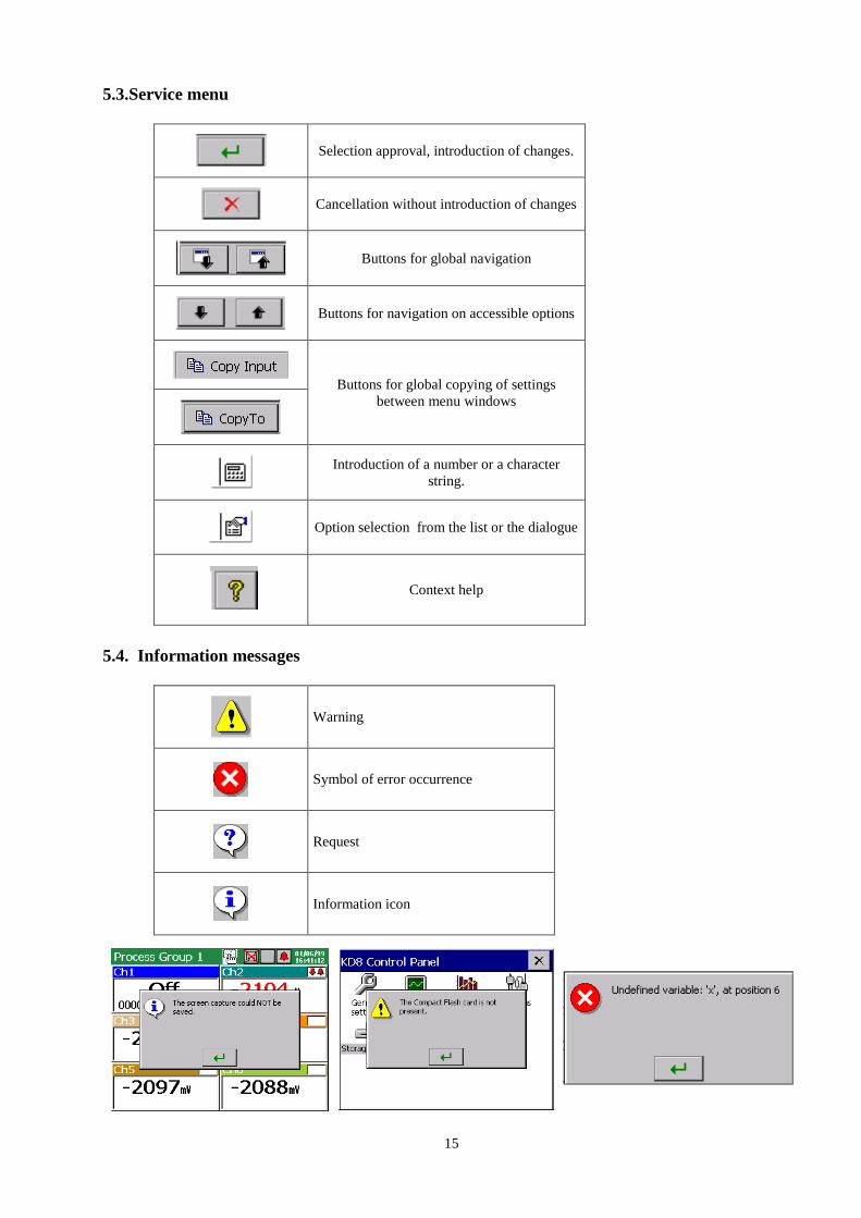
5.3.Service menu
Selection approval, introduction of changes.
Cancellation without introduction of changes
Buttons for global navigation
Buttons for navigation on accessible options
Buttons for global copying of settings
between menu windows
Introduction of a number or a character
string.
Option selection from the list or the dialogue
Context help
5.4. Information messages
Warning
Symbol of error occurrence
Request
Information icon

16
5.5. Dialogues
- Selection:
Single: Multiple:
- Introduction of numbers
- Introduction of a character string (small and capital letters, numbers and special characters,
password)
Small and capital letters
Numbers and special characters: Password (replaced by dots):
6. STARTING THE RECORDER
After connecting the supply, the start screen appears with the producer’s logo.
The logo is displayed during the time necessary for the initialization of recorder processes.
Next, the screen of data visualization appears, which was displayed at the last recorder
disconnection from the network.
Touching the screen in any place brings the Context Menu up.
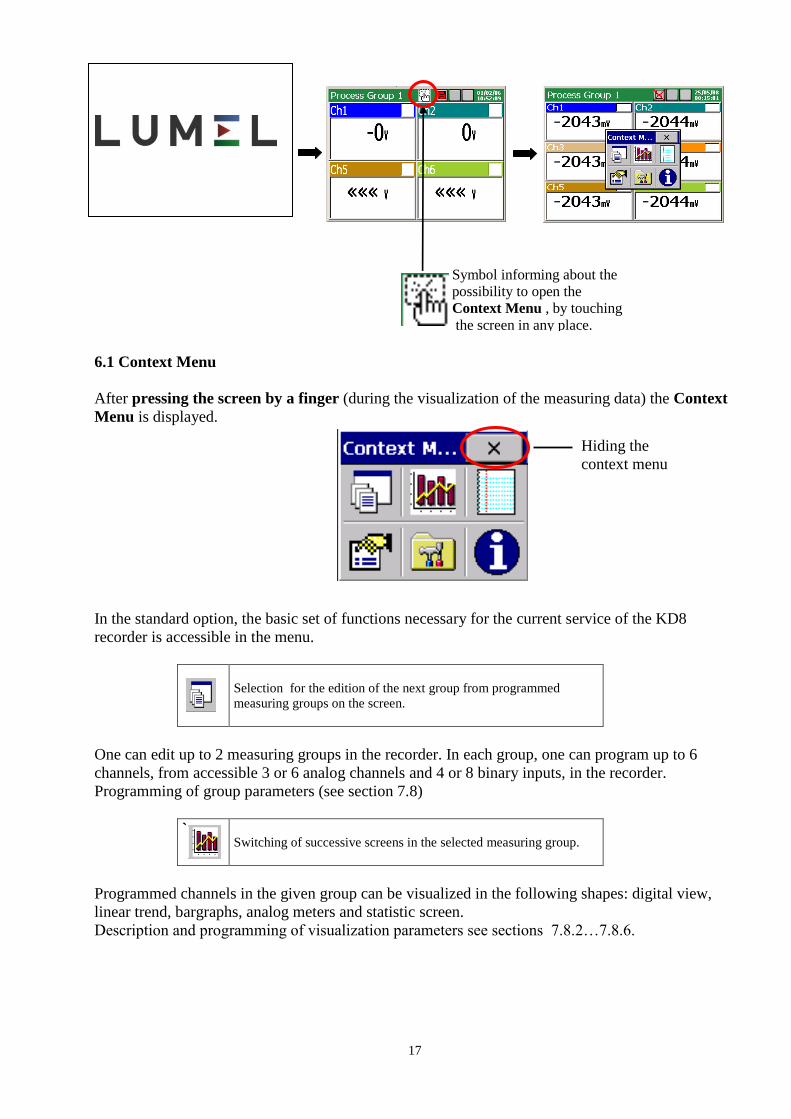
17
Symbol informing about the
possibility to open the
Context Menu , by touching
the screen in any place.
6.1 Context Menu
After pressing the screen by a finger (during the visualization of the measuring data) the Context
Menu is displayed.
In the standard option, the basic set of functions necessary for the current service of the KD8
recorder is accessible in the menu.
Selection for the edition of the next group from programmed
measuring groups on the screen.
One can edit up to 2 measuring groups in the recorder. In each group, one can program up to 6
channels, from accessible 3 or 6 analog channels and 4 or 8 binary inputs, in the recorder.
Programming of group parameters (see section 7.8)
`
Switching of successive screens in the selected measuring group.
Programmed channels in the given group can be visualized in the following shapes: digital view,
linear trend, bargraphs, analog meters and statistic screen.
Description and programming of visualization parameters see sections 7.8.2…7.8.6.
Hiding the
context menu

18
Switching of the alarm and the audit log view.
Information concerning events occurring during the recorder work is stored in logs
(see section 7.12)
Caution: After exceeding the log capacity, the oldest events are overwritten in the view.
Opening of the service options accessible for the selected screen
type.
The window with systemic information from the KD8 control panel is accessible from the context
menu.
Opening of the system information window from the control panel.
Following options are accessible for screens: digital, bargraphs, analog, and statistic.
- turn on/off the switching of screens (automatic switching), see section 7.8.7,
- recording of archive data on CF, see section.8.1.3,
- removal of the CF card, see section 8.1.6,
- confirmation of alarms, see section 7.7.2
- operator’s messages, see section 7.13
Following options are accessible for the linear screen:
- time scale (for the screen),
- visualized signals,
- zoom signals, see section 7.9,
- transition to the archive mode, see section 8.2,
- turning on/off the switching of screen, see section 7.8.7,
- storage of archive data on CF, see section 8.1.6,
- removal of the CF card, see section 8.1.6.
- confirmation of alarms, see section 7.7.2
- operator’s messages, see section 7.13
For each logs (alarms and audits) following options are accessible:
- Reset this log / Reset all logs / Filter by groups…
- Confirmation of alarms, see section 8.5.2
Opening of the KD8 Control Panel window with programming
options of the recorder KD8 parameters.
- transition to the configuration of recorder parameters in the “KD8 Control Panel “window,
see section 6.2.
19
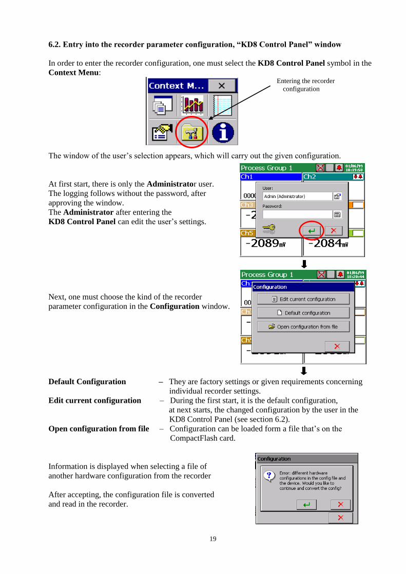
6.2. Entry into the recorder parameter configuration, “KD8 Control Panel” window
In order to enter the recorder configuration, one must select the KD8 Control Panel symbol in the
Context Menu:
The window of the user’s selection appears, which will carry out the given configuration.
At first start, there is only the Administrator user.
The logging follows without the password, after
approving the window.
The Administrator after entering the
KD8 Control Panel can edit the user’s settings.
Next, one must choose the kind of the recorder
parameter configuration in the Configuration window.
Default Configuration – They are factory settings or given requirements concerning
individual recorder settings.
Edit current configuration – During the first start, it is the default configuration,
at next starts, the changed configuration by the user in the
KD8 Control Panel (see section 6.2).
Open configuration from file – Configuration can be loaded form a file that’s on the
CompactFlash card.
Information is displayed when selecting a file of
another hardware configuration from the recorder
After accepting, the configuration file is converted
and read in the recorder.
Entering the recorder
configuration

20
The KD8 Control Panel appears.
It is the initial point for carrying out the full
configuration of the KD8 recorder.
7. CONFIGURING THE RECORDER
The KD8 Control Panel is the window in which we obtain the direct access to the KD8
operating menu:
- general settings of the recorder, see section 7.1
- configuration of channels, see section 7.7
- configuration of alarms A1 and A2 in analog measuring channels, see section 7.6.
- setting of visualization and archiving parameters, see section 7.6
- configuration of event logs (alarms and audits), see section 7.12
- setting of RS485 interface parameters, see section 7.2,
- service of the CF card, review of files, see section 8.1
- read out of information about the recorder, see section 7.4
- setting of access principles to recorder configuration changes , see section 7.3
Note: 1. In descriptions of the KD8 Control Panel menu, exemplary data are written in italics.
2. During the recorder configuration, the measurement and data storage is carried according to
existing settings. When we enter new settings, after accepting changes, a break in storage,
initialization of changes and starting of recording with new data follows. Only in case of the date
change, the change is immediately introduced and the storage lasts acc. to the new setting.
7.1 General settings
After pressing the icon,
the configuration of general parameters is
displayed: recorder description, selection of
the menu language, setting of the date and time,
selection of the temperature unit, capacity of the
event log (audits), time of screen blanking, setting
of screen brightness. The procedure of the touch
screen calibration is also accessible (see section 7.1).

21
Programming menu of general settings:
Basic
Device ID: KD8
Description edition
Device description: Screen
Recorder
Description edition
Language: English
Selection:
- Polish, Russian, English, Italian,
French, Romanian, German,
Portuguese (Brazil)
Time and date: 12:00:00
(24/01/08)
- Time setting:
- Selection of the time zone
- Setting of the automatic time change
(summer/winter)
Temperature unit: ºC
LCD screen
Screen saver:
15 min.
Selection: - Disabled
- 5,10,15,30 min.
- 1,6,12 hours
LCD backlight: 100% Setting of the screen brightness
Touch screen
calibration:
See section 8.3
CompactFlash Selection: fast formatting of CF card/full formatting of CF card
Logs
Audit log size:
Alarm log size:
50
50
Edition of the
parameter value
Other Operator messages:
MSG1…
Choice:
- Choice and edition of
messages MSG1..10
7.2 Modbus Slave configuration
After pressing the icon, the
configuration window of the Modbus
communication protocol is showed.
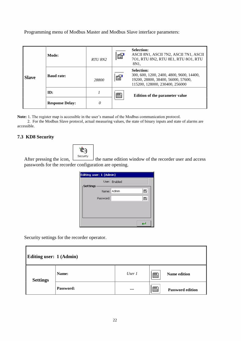
22
Programming menu of Modbus Master and Modbus Slave interface parameters:
Slave
Mode:
RTU 8N2
Selection:
ASCII 8N1, ASCII 7N2, ASCII 7N1, ASCII
7O1, RTU 8N2, RTU 8E1, RTU 8O1, RTU
8N1,
Baud rate:
28800
Selection:
300, 600, 1200, 2400, 4800, 9600, 14400,
19200, 28800, 38400, 56000, 57600,
115200, 128000, 230400, 256000
ID: 1
Edition of the parameter value
Response Delay: 0
Note: 1. The register map is accessible in the user’s manual of the Modbus communication protocol.
2. For the Modbus Slave protocol, actual measuring values, the state of binary inputs and state of alarms are
accessible.
7.3 KD8 Security
After pressing the icon, the name edition window of the recorder user and access
passwords for the recorder configuration are opening.
Security settings for the recorder operator.
Editing user: 1 (Admin)
Settings
Name: User 1
Name edition
Password: ....
Password edition
23
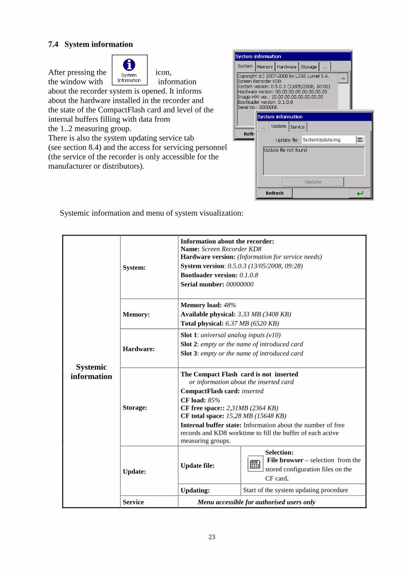
7.4 System information
After pressing the icon,
the window with information
about the recorder system is opened. It informs
about the hardware installed in the recorder and
the state of the CompactFlash card and level of the
internal buffers filling with data from
the 1..2 measuring group.
There is also the system updating service tab
(see section 8.4) and the access for servicing personnel
(the service of the recorder is only accessible for the
manufacturer or distributors).
Systemic information and menu of system visualization:
Systemic
information
System:
Information about the recorder: Name: Screen Recorder KD8
Hardware version: (Information for service needs)
System version: 0.5.0.3 (13/05/2008, 09:28)
Bootloader version: 0.1.0.8
Serial number: 00000000
Memory:
Memory load: 48%
Available physical: 3.33 MB (3408 KB)
Total physical: 6.37 MB (6520 KB)
Hardware:
Slot 1: universal analog inputs (v10)
Slot 2: empty or the name of introduced card
Slot 3: empty or the name of introduced card
Storage:
The Compact Flash card is not inserted or information about the inserted card
CompactFlash card: inserted
CF load: 85%
CF free space:: 2,31MB (2364 KB)
CF total space: 15,28 MB (15648 KB)
Internal buffer state: Information about the number of free
records and KD8 worktime to fill the buffer of each active
measuring groups.
Update: Update file:
Selection:
File browser – selection from the
stored configuration files on the
CF card.
Updating: Start of the system updating procedure
Service Menu accessible for authorised users only

24
7.5. CF card
After pressing the icon,
when the CF card is inserted,
the file browser window is opened.
When there is no card, suitable
message appears.
7.6. Configuration, visualization and archiving of the channel group
After pressing the icon,
the window of programming and visualization
of 1 or 2 groups of channels is opening.
One must define the group name, select 1..6 from
accessible 7 or 14 channels in KD8 (3 or 6 analog
inputs and 4 or 8 binary inputs) and program
visualization parameters and data archive (see section 7.8).
Programming menu of the selected group of channels:
Edited group: Selection of the group:
1 (Process Group 1) ... 4 (Process Group 4)
General
Group:
enabled Selection:
disabled / enabled
Settings:
Name:
Process Group 4
Name edition
Channels: 1,2,3,4,5,6
Selection:
Select for the given
group 1...6 channels
from accessible in
the recorder up to 14
channels
(AI1..6 i BI1..8)
Archive
time:
0 min., 10 sec.,
0 ms
Selection:
Choice and edition of
time base of time base
parameters
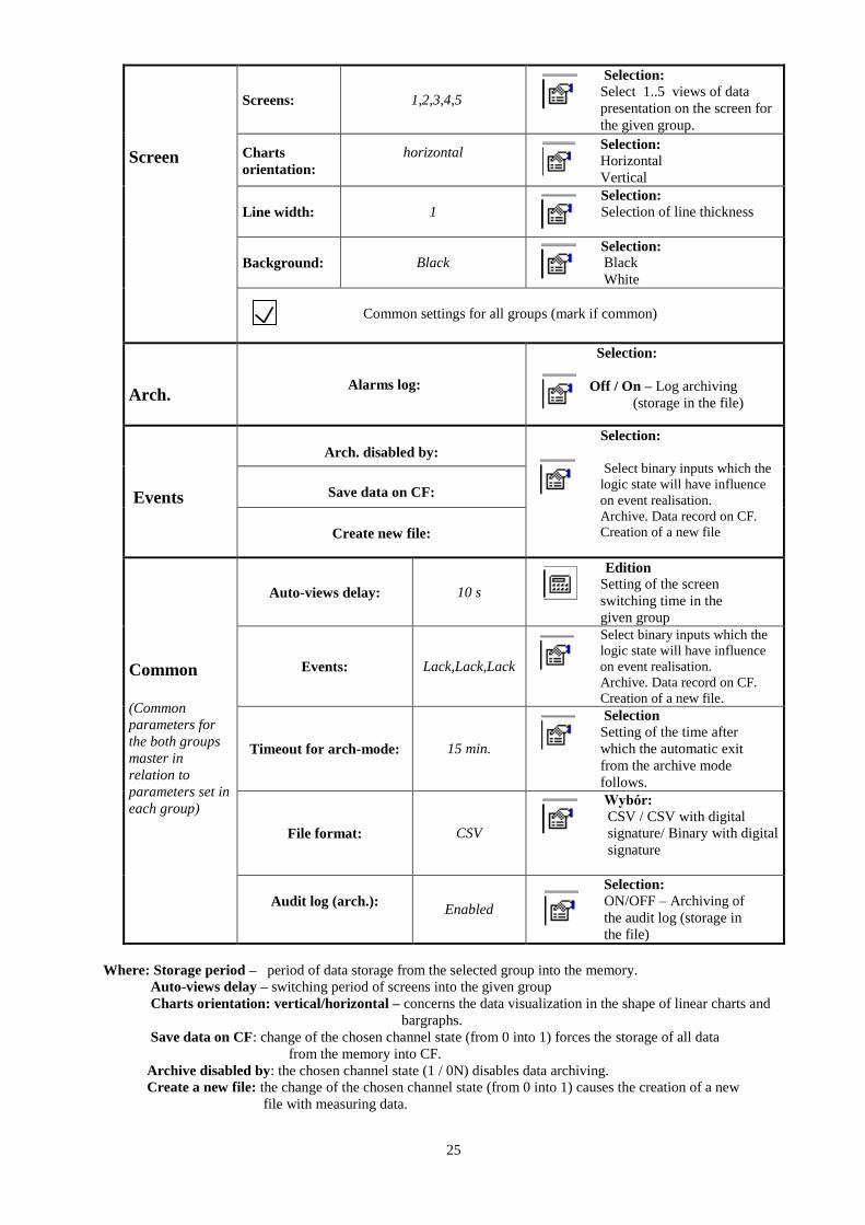
25
Screen
Screens: 1,2,3,4,5
Selection:
Select 1..5 views of data
presentation on the screen for
the given group.
Charts
orientation:
horizontal
Selection:
Horizontal
Vertical
Line width:
1
Selection:
Selection of line thickness
Background:
Black
Selection:
Black
White
Common settings for all groups (mark if common)
Arch. Alarms log:
Selection:
Off / On – Log archiving
(storage in the file)
Events
Arch. disabled by:
Selection:
Select binary inputs which the
logic state will have influence
on event realisation.
Archive. Data record on CF.
Creation of a new file
Save data on CF:
Create new file:
Common
(Common
parameters for
the both groups
master in
relation to
parameters set in
each group)
Auto-views delay:
10 s
Edition
Setting of the screen
switching time in the
given group
Events:
Lack,Lack,Lack
Select binary inputs which the
logic state will have influence
on event realisation.
Archive. Data record on CF.
Creation of a new file.
Timeout for arch-mode:
15 min.
Selection
Setting of the time after
which the automatic exit
from the archive mode
follows.
File format:
CSV
Wybór:
CSV / CSV with digital
signature/ Binary with digital
signature
Audit log (arch.):
Enabled
Selection:
ON/OFF – Archiving of
the audit log (storage in
the file)
Where: Storage period – period of data storage from the selected group into the memory.
Auto-views delay – switching period of screens into the given group
Charts orientation: vertical/horizontal – concerns the data visualization in the shape of linear charts and
bargraphs.
Save data on CF: change of the chosen channel state (from 0 into 1) forces the storage of all data
from the memory into CF.
Archive disabled by: the chosen channel state (1 / 0N) disables data archiving.
Create a new file: the change of the chosen channel state (from 0 into 1) causes the creation of a new
file with measuring data.
26
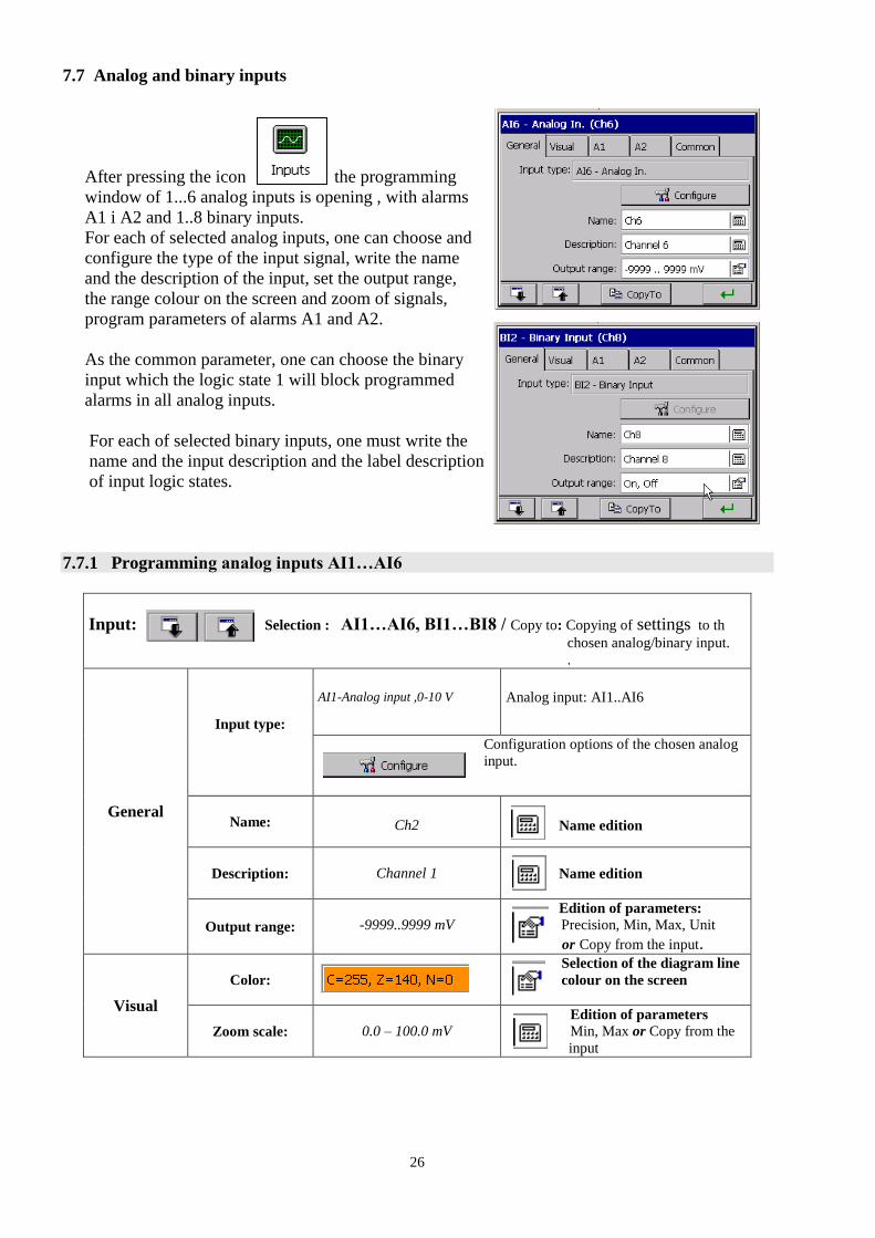
7.7 Analog and binary inputs
After pressing the icon , the programming
window of 1...6 analog inputs is opening , with alarms
A1 i A2 and 1..8 binary inputs.
For each of selected analog inputs, one can choose and
configure the type of the input signal, write the name
and the description of the input, set the output range,
the range colour on the screen and zoom of signals,
program parameters of alarms A1 and A2.
As the common parameter, one can choose the binary
input which the logic state 1 will block programmed
alarms in all analog inputs.
For each of selected binary inputs, one must write the
name and the input description and the label description
of input logic states.
7.7.1 Programming analog inputs AI1…AI6
Input: Selection : AI1…AI6, BI1…BI8 / Copy to: Copying of settings to th
chosen analog/binary input.
.
General
Input type:
AI1-Analog input ,0-10 V
Analog input: AI1..AI6
Configuration options of the chosen analog
input.
Name:
Ch2
Name edition
Description:
Channel 1
Name edition
Output range:
-9999..9999 mV Edition of parameters:
Precision, Min, Max, Unit
or Copy from the input.
Visual
Color:
Selection of the diagram line
colour on the screen
Zoom scale:
0.0 – 100.0 mV Edition of parameters
Min, Max or Copy from the
input

27
Alarm:
A1 / A2
Alarm type: Min
Selection:
Disabled, Min, Max, Range On, Range Off
Alarm value:
2.00
Edition of the parameter value
Alarm hyst.:
Value; 0.00;
0 sec.
Type:
Percentage, Value,
Percentage Off, Value Off
Percentage:
Edition of the
parameter value
Hyst. value:
Edition of the
parameter value
Time:
Edition of the
parameter value
Alarm controls:
Accept; None,
Disabled
Confirm type: Selection:
None, Latch, Accept
Alarm disabled by:
Selection:
None,
Binary Inputs
Input control: Selection:
Enabled/Disabled
Alarm log:
Enabled Selection:
On/Off – storage of the alarm in the log file
Common Alarms disabled
by:
Lack Selection:
Lack, Binary inputs BI1..BI8
Output range: - During measurement of the input quantity, the proportional output value in limits defined by this
parameter is displayed on the screen.
Zoom scale: - During the display of the analog screen (linear chart), after opening the context menu
and selecting the option: Zoom scale in it, the selected channel is displayed on the analog
screen, in limits defined by this parameter (see chapter 7.9)
Parameters common for all channels (can be globally modified through the change of each of them in
any channel):
Alarms disabled by: - The activation follows if the selected source will be in the logic state 1.
7.7.1.1 Selection and configuration of an input for a channel.
Configuration: AI8 – Analog inputs
General
Type of input
signal: Voltage
Selection of signal
type
Range: -9999…9999
Range edition
28
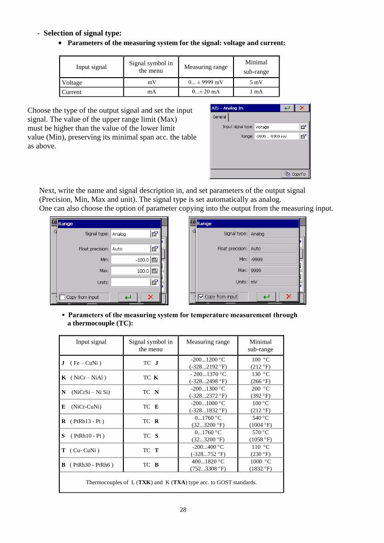
- Selection of signal type:
Parameters of the measuring system for the signal: voltage and current:
Input signal Signal symbol in
the menu Measuring range
Minimal
sub-range
Voltage mV 0... ± 9999 mV 5 mV
Current mA 0...± 20 mA 1 mA
Choose the type of the output signal and set the input
signal. The value of the upper range limit (Max)
must be higher than the value of the lower limit
value (Min), preserving its minimal span acc. the table
as above.
Next, write the name and signal description in, and set parameters of the output signal
(Precision, Min, Max and unit). The signal type is set automatically as analog.
One can also choose the option of parameter copying into the output from the measuring input.
(2 nowe
Parameters of the measuring system for temperature measurement through
a thermocouple (TC):
Input signal Signal symbol in
the menu
Measuring range Minimal
sub-range
J ( Fe – CuNi ) TC J -200...1200 C
(-328...2192 F)
100 C
(212 F)
K ( NiCr – NiAl ) TC K - 200...1370 C
(-328...2498 F)
130 C
(266 F)
N (NiCrSi – Ni Si) TC N -200...1300 C
(-328...2372 F)
200 C
(392 F)
E (NiCr-CuNi) TC E -200...1000 C
(-328...1832 F)
100 C
(212 F)
R ( PtRh13 - Pt ) TC R 0...1760 C
(32...3200 F)
540 C
(1004 F)
S ( PtRh10 - Pt ) TC S 0...1760 C
(32...3200 F)
570 C
(1058 F)
T ( Cu- CuNi ) TC T -200...400 C
(-328...752 F)
110 C
(230 F)
B ( PtRh30 - PtRh6 ) TC B 400...1820 C
(752...3308 F)
1000 C
(1832 F)
Thermocouples of L (TXK) and K (TXA) type acc. to GOST standards.

29
After selecting the signal type, set the upper (Max)
and lower (Min) limit of the input signal. The value
of the upper range limit (Max) must be higher than
the value of the lower limit value (Min), preserving
its minimal span acc. the table as above.
Cold junction compensation:
Defines the way of the thermocouple cold junction
- Internal (ACJC): Sets the self-acting cold
junction compensation by the temperature
sensor placed on the measuring package.
- External: the temperature of cold junction,
23ºC set as a standard, can be changed.
Next, write the name and signal description in, and set parameters of the output signal
(Precision, Min, Max and unit). The signal type is set automatically as analog.
One can also choose the option of parameter copying into the output from the measuring input.
Parameters of the measuring system for temperature measurement through a resistance
thermometer (RTD)
Input signal Signal symbol in
the menu
Measuring range Minimal
sub-range
Resistance thermometer (RTD):
Pt 100 Pt 100 - 200...850 C
(-328...1562 F)
50 C (122 F)
Pt 500 Pt 500 - 200...850 C
(-328...1562 F)
Pt 1000 Pt 1000 - 200...850 C
(-328...1562 F)
Ni 100 Ni 100 - 60...180 C
(-76...356 F)
Ni 90,26 Ni 90,26 (P1) - 50...150 C
(-58...302 F)
Cu 100 Cu 100 -50... 180 C
(-58...356 F)
Thermometer resistances PT and Cu (GR21, 50P, 100P, 50M,100M) type acc. to
GOST 6651-78 and GOST6651-94 standards.
After selecting the signal type, set the upper (Max)
and lower (Min) limit of the input signal. The value
of the upper range limit (Max) must be higher than
the value of the lower limit value (Min), preserving
its minimal span acc. the table as above.
30
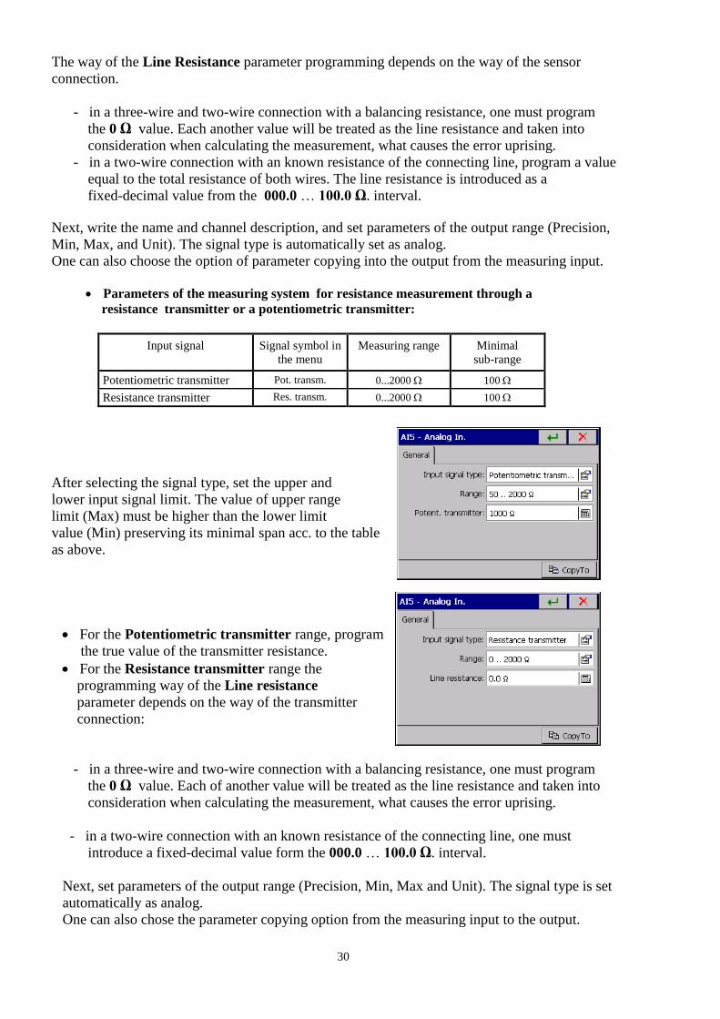
The way of the Line Resistance parameter programming depends on the way of the sensor
connection.
- in a three-wire and two-wire connection with a balancing resistance, one must program
the 0 Ω value. Each another value will be treated as the line resistance and taken into
consideration when calculating the measurement, what causes the error uprising.
- in a two-wire connection with an known resistance of the connecting line, program a value
equal to the total resistance of both wires. The line resistance is introduced as a
fixed-decimal value from the 000.0 … 100.0 Ω. interval.
Next, write the name and channel description, and set parameters of the output range (Precision,
Min, Max, and Unit). The signal type is automatically set as analog.
One can also choose the option of parameter copying into the output from the measuring input.
Parameters of the measuring system for resistance measurement through a
resistance transmitter or a potentiometric transmitter:
Input signal Signal symbol in
the menu
Measuring range Minimal
sub-range
Potentiometric transmitter Pot. transm. 0...2000 100
Resistance transmitter Res. transm. 0...2000 100
After selecting the signal type, set the upper and
lower input signal limit. The value of upper range
limit (Max) must be higher than the lower limit
value (Min) preserving its minimal span acc. to the table
as above.
For the Potentiometric transmitter range, program
the true value of the transmitter resistance.
For the Resistance transmitter range the
programming way of the Line resistance
parameter depends on the way of the transmitter
connection:
- in a three-wire and two-wire connection with a balancing resistance, one must program
the 0 Ω value. Each of another value will be treated as the line resistance and taken into
consideration when calculating the measurement, what causes the error uprising.
- in a two-wire connection with an known resistance of the connecting line, one must
introduce a fixed-decimal value form the 000.0 … 100.0 Ω. interval.
Next, set parameters of the output range (Precision, Min, Max and Unit). The signal type is set
automatically as analog.
One can also chose the parameter copying option from the measuring input to the output.
31
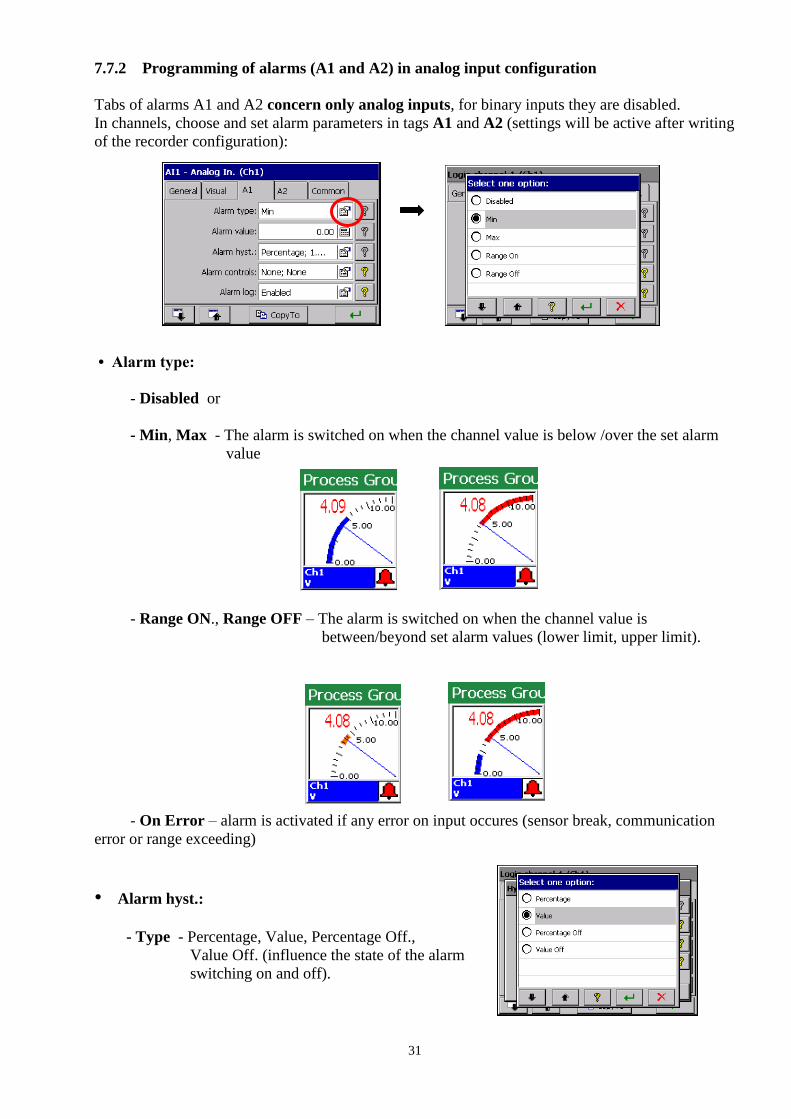
7.7.2 Programming of alarms (A1 and A2) in analog input configuration
Tabs of alarms A1 and A2 concern only analog inputs, for binary inputs they are disabled.
In channels, choose and set alarm parameters in tags A1 and A2 (settings will be active after writing
of the recorder configuration):
• Alarm type:
- Disabled or
- Min, Max - The alarm is switched on when the channel value is below /over the set alarm
value
- Range ON., Range OFF – The alarm is switched on when the channel value is
between/beyond set alarm values (lower limit, upper limit).
- On Error – alarm is activated if any error on input occures (sensor break, communication
error or range exceeding)
• Alarm hyst.:
- Type - Percentage, Value, Percentage Off.,
Value Off. (influence the state of the alarm
switching on and off).

32
Percentage (for type Percentage and Percentage Off)
– edition of values in percentage of the
channel range.
Hyst. value (for type Value and Value Off)
– edition of values in channel range units
(positive values)
Time
(hysteresis value in time units)
– edition of values
After programming the alarm hysteresis, valuable or in percentage, and temporary higher
than zero, the action of the alarm follows when both conditions are fulfilled simultaneously.
Fig. 1 Functional diagram of the value Off alarm type.

33
Fig. 2 Functional diagram of the Value On alarm type.
Fig. 3 Functional diagram of the MAX alarm type taking in consideration the
hysteresis of Value and Time type
Alarm controls:
34
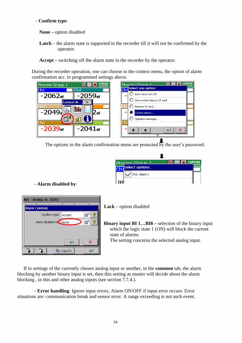
- Confirm type:
None – option disabled
Latch – the alarm state is supported in the recorder till it will not be confirmed by the
operator.
Accept – switching off the alarm state in the recorder by the operator.
During the recorder operation, one can choose in the context menu, the option of alarm
confirmation acc. to programmed settings above.
The options in the alarm confirmation menu are protected by the user’s password.
- Alarm disabled by:
Lack – option disabled
Binary input BI 1…BI8 – selection of the binary input
which the logic state 1 (ON) will block the current
state of alarms.
The setting concerns the selected analog input.
If in settings of the currently chosen analog input or another, in the common tab, the alarm
blocking by another binary input is set, then this setting as master will decide about the alarm
blocking , in this and other analog inputs (see section 7.7.4.).
- Error handling: Ignore input errors, Alarm ON/OFF if input error occurs. Error
situations are: communication break and sensor error. A range exceeding is not such event.

35
Storage in the log
Disabled/Enabled – Storage of alarm
messages in the alarm log.
7.7.3 Configuration of BI1…BI8 binary input parameters
The signal type of the output channel is set automatically as binary and will be visualized and
archived in this form.
Write the name and channel description in the General tab and the description of output logic states
1 and 0 of the channel (as standard, it is ON and OFF). Programming of alarm parameters in
disabled (A1 and A2 tabs).
Parameters set in the selected channel in the Common tab concern all remaining channels.
In each of other channel, they can be modified.

36
7.7.4 Common parameters for binary inputs
In the Common Binary Input tab, one can choose
the binary input 1...8 which the logic state 1 (ON)
will block the current state of all alarms in
measuring inputs.
It is a common setting (master) for all analog measuring
inputs. It can be changed in the level of each another
analog input.
7.8. Programming of measuring groups
For the visualization and analysis of measuring data related e.g. with the defined technological
process, one can connect channels in 1..2 measuring groups (each with 1 .. 6 channels) for which
an individual set of parameters is chosen.
After selecting in the KD8 Control Panel window the icon , the window of channel
group edition is open.
7.8.1 Programming of group parameters
For each edited group of channels
( KD8 Control Panel → Visualization and Archiving
→ Edited group) in the General tab, one can select
1...6 channels (analog and binary inputs) presentation
from 14 accessible (for executions with 6
measuring inputs and 8 binary inputs),
channels in the recorder, write the group name
and set the time base for the group.
Selection of the
group Parameter copying for
other groups
do innych grup
Channel selection
for the group
group
Edition of the
group name
nazwy grupy
Setting of the
time base
Enabling/Disabling of
the group
37
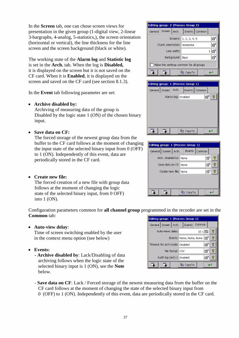
In the Screen tab, one can chose screen views for
presentation in the given group (1-digital view, 2-linear
3-bargraphs, 4-analog, 5-statistics,), the screen orientation
(horizontal or vertical), the line thickness for the line
screen and the screen background (black or white).
The working state of the Alarm log and Statistic log
is set in the Arch. tab. When the log is Disabled,
it is displayed on the screen but it is not saved on the
CF card. When it is Enabled, it is displayed on the
screen and saved on the CF card (see section 8.1.3).
In the Event tab following parameter are set:
Archive disabled by:
Archiving of measuring data of the group is
Disabled by the logic state 1 (ON) of the chosen binary
input.
Save data on CF:
The forced storage of the newest group data from the
buffer to the CF card follows at the moment of changing
the input state of the selected binary input from 0 (OFF)
to 1 (ON). Independently of this event, data are
periodically stored in the CF card.
Create new file:
The forced creation of a new file with group data
follows at the moment of changing the logic
state of the selected binary input, from 0 OFF)
into 1 (ON).
Configuration parameters common for all channel group programmed in the recorder are set in the
Common tab:
Auto-view delay:
Time of screen switching enabled by the user
in the context menu option (see below)
Events:
- Archive disabled by: Lack/Disabling of data
archiving follows when the logic state of the
selected binary input is 1 (ON), see the Note
below.
- Save data on CF: Lack / Forced storage of the newest measuring data from the buffer on the
CF card follows at the moment of changing the state of the selected binary input from
0 (OFF) to 1 (ON). Independently of this event, data are periodically stored in the CF card.

38
The analog output value of the channel higher than zero is
interpreted in KD8 as a logic state (ON) of the given channel.
- Create new files: Lack/New files with data of measuring groups will be created at the moment
of chanching the logic state of the selected binary input from 0 (OFF) into 1 (ON).
Output time from the archive: The set time of automatic output from archive data review, in
case when the user forgot to close it. The time is counted from the last pressure of the button in
the context menu.
File format: Selection of the format which measuring data on the CF card will be stored in,
CSV with the digital signature or CSV without the digital signature (see section 7.10)
Audit log: When it is Enabled it is displayed on the screen (see section 7.12) and saved on the
CF card. When it is set as Disabled it is displayed on the screen, but it is not saved on the CF
card.
Parameters in the Common tab can be modified from the level of each other measuring group.
Each from channel groups can be disabled. Measuring data from particular groups are stored in the
CF memory card of 8 MB capacity, in the format *.csv or binary.
The text file in format *.csv is serviced by the Excel program, and the binary file can be reviewed in
the KD Archive program (see section 9.4).
Structure of the channel group file stored in CF card, with measuring data:
Year, Month, Day Hour, Minute, Second, Group symbol File name
During the display of measuring data, one can switch screen views manually through successive
pressures of the view icon in the Context Menu. One can also in the option window enable the
previously (see above) programmed automatic cycle of their switching.

39
Information about the current recorder operation state are displayed on recorder screens, actual
measurement value, alarm information, range overflows, sensor breaks, lack of data, and on
statistics and bargraph screens, information about minimal and maximal measurement values in the
current session period of the recorder operation.
7.8.2 Digital view of channel group.
The type and the alarm value, in the given channel, can be read out in the KD8 Control Panel, in
the menu of the Input icon.
Manually switching
of screens
Enabling of screen
automatic switching
Signalling of alarm occurrence in the recorder
Min type of alarm in the logic channel 2
Alarm typu Min w 2 kanale logicznym
Overflow of the lower measuring range limit
Alarm of Max type
Overflow of the upper measuring range
limit, alarm of Max type in the channel
Przekroczenie górnej granicy zakresu
pomiarowego, alarm typu Max w kanale
Signal of logic type
Break of the measuring sensor
pomiarowego
40
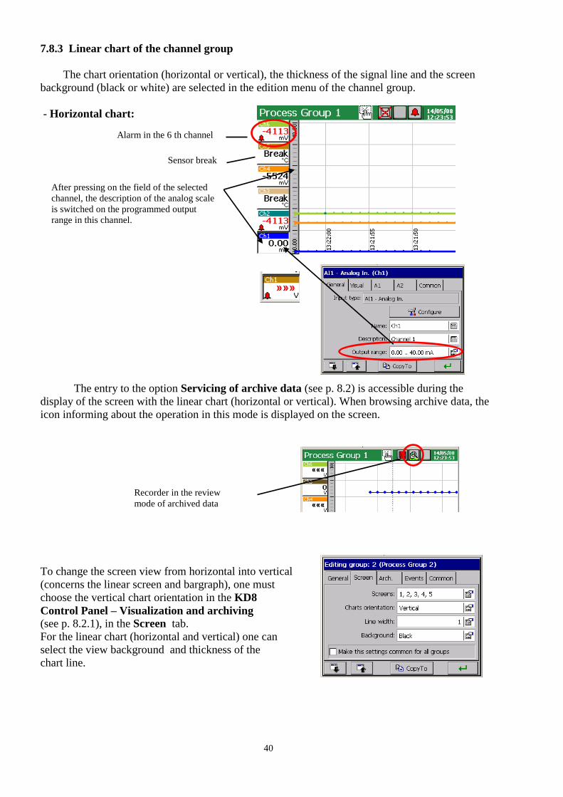
7.8.3 Linear chart of the channel group
The chart orientation (horizontal or vertical), the thickness of the signal line and the screen
background (black or white) are selected in the edition menu of the channel group.
- Horizontal chart:
The entry to the option Servicing of archive data (see p. 8.2) is accessible during the
display of the screen with the linear chart (horizontal or vertical). When browsing archive data, the
icon informing about the operation in this mode is displayed on the screen.
To change the screen view from horizontal into vertical
(concerns the linear screen and bargraph), one must
choose the vertical chart orientation in the KD8
Control Panel – Visualization and archiving
(see p. 8.2.1), in the Screen tab.
For the linear chart (horizontal and vertical) one can
select the view background and thickness of the
chart line.
Alarm in the 6 th channel
After pressing on the field of the selected
channel, the description of the analog scale
is switched on the programmed output
range in this channel.
Sensor break
Recorder in the review
mode of archived data
41
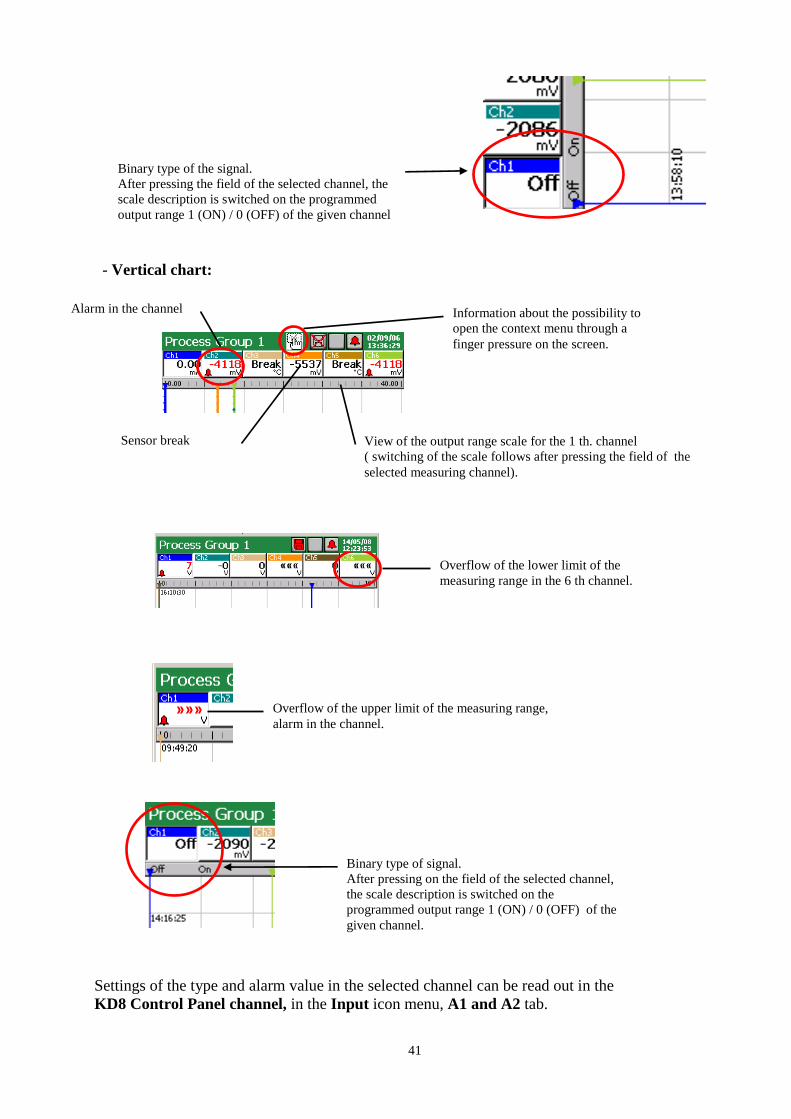
- Vertical chart:
Settings of the type and alarm value in the selected channel can be read out in the
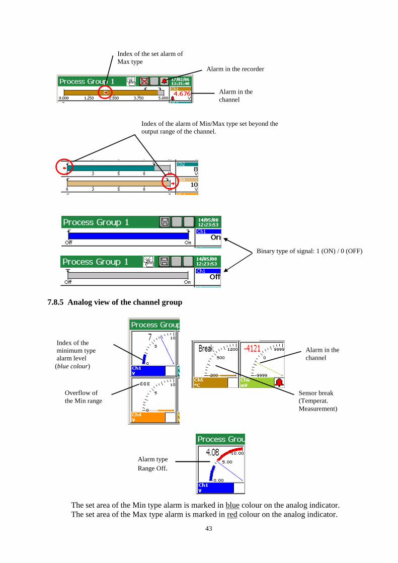
KD8 Control Panel channel, in the Input icon menu, A1 and A2 tab.
Binary type of the signal.
After pressing the field of the selected channel, the
scale description is switched on the programmed
output range 1 (ON) / 0 (OFF) of the given channel
Overflow of the upper limit of the measuring range,
alarm in the channel.
Binary type of signal.
After pressing on the field of the selected channel,
the scale description is switched on the
programmed output range 1 (ON) / 0 (OFF) of the
given channel.
Sensor break
Information about the possibility to
open the context menu through a
finger pressure on the screen.
View of the output range scale for the 1 th. channel
( switching of the scale follows after pressing the field of the
selected measuring channel).
Alarm in the channel
Overflow of the lower limit of the
measuring range in the 6 th channel.
42
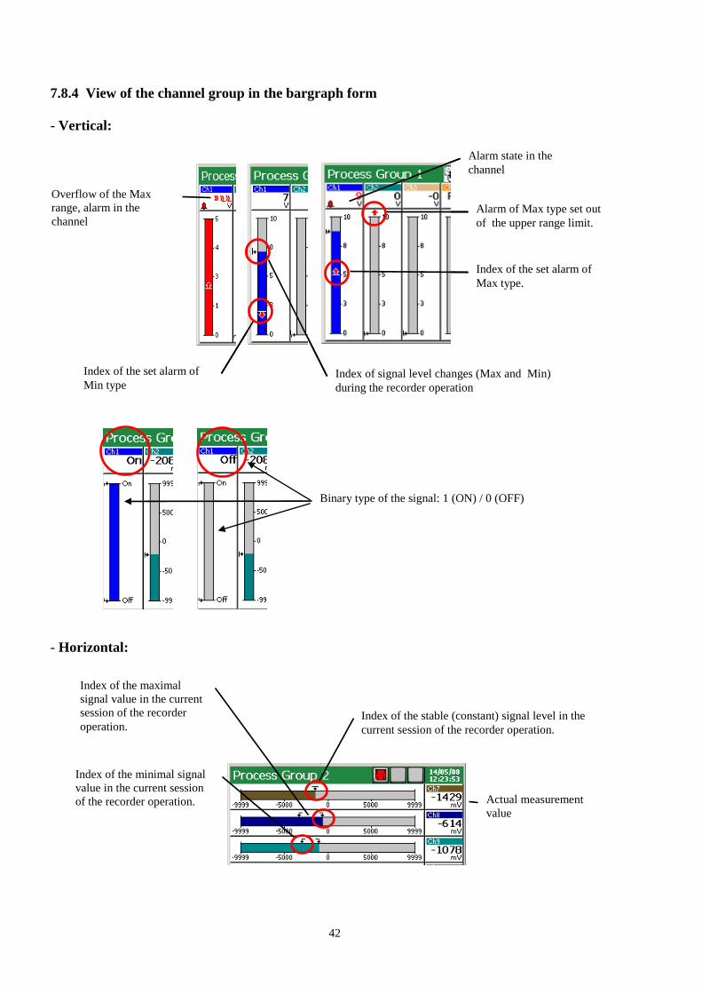
7.8.4 View of the channel group in the bargraph form
- Vertical:
- Horizontal:
Index of the set alarm of
Max type
Index of the set alarm of
Min type
Alarm state in the
channel
Index of signal level changes (Max and
Min) during the recorder operation.
Alarm of Max type set
beyond the upper range
limit of output channel.
Index of the set alarm of
Max type.
Index of the set alarm of
Min type
Alarm state in the
channel
Overflow of the Max
range, alarm in the
channel
Index of signal level changes (Max and Min)
during the recorder operation
Alarm of Max type set out
of the upper range limit.
Binary type of the signal: 1 (ON) / 0 (OFF)
Index of the stable (constant) signal level in the
current session of the recorder operation.
Index of the minimal signal
value in the current session
of the recorder operation.
Index of the maximal
signal value in the current
session of the recorder
operation.
Actual measurement
value
43
7.8.5 Analog view of the channel group
The set area of the Min type alarm is marked in blue colour on the analog indicator.
The set area of the Max type alarm is marked in red colour on the analog indicator.
Sensor break
(Temperat.
Measurement)
Index of the
minimum type
alarm level
(blue colour)
Overflow of
the Min range
Alarm in the
channel
Alarm type
Range Off.
Index of the set alarm of
Max type
Alarm in the
channel
Alarm in the recorder
Index of the alarm of Min/Max type set beyond the
output range of the channel.
Binary type of signal: 1 (ON) / 0 (OFF)

44
7.8.6 Statistic view of the channel group
On the statistic screen following values are displayed: minimal and maximal values of the measured
signal in the current session period of the recorder operation, mean values, current signal value, is
signalled and the messages about the range overflow, sensor break, current alarm state, messages
about the range overflow and sensor breaks, the alarm state in the recorder and the given measuring
channel is also signalled.
Binary type of the signal
Value min. / max of the
signal in the channel
Current signal value,
alarm state in the channel
Mean value of the
signal
sygna
Alarm state in the
recorder
Current signal state of
binary type
Overflow of Max range
Index of the programmed
Max type alarm level.
(red colour)
Overflow of Max range,
alarm enabled in the channel
Dot indexes of measuring range
overflow: Max (red) and Min (blue)
Max alarm type enabled
Binary type of signal: 1 (ON) / 0 (OFF)
45
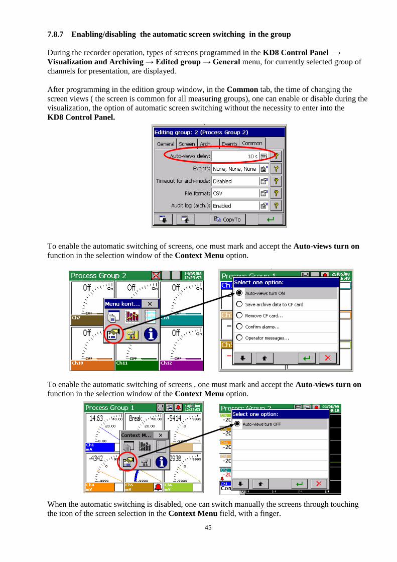
7.8.7 Enabling/disabling the automatic screen switching in the group
During the recorder operation, types of screens programmed in the KD8 Control Panel →
Visualization and Archiving → Edited group → General menu, for currently selected group of
channels for presentation, are displayed.
After programming in the edition group window, in the Common tab, the time of changing the
screen views ( the screen is common for all measuring groups), one can enable or disable during the
visualization, the option of automatic screen switching without the necessity to enter into the
KD8 Control Panel.
To enable the automatic switching of screens, one must mark and accept the Auto-views turn on
function in the selection window of the Context Menu option.
To enable the automatic switching of screens , one must mark and accept the Auto-views turn on
function in the selection window of the Context Menu option.
When the automatic switching is disabled, one can switch manually the screens through touching
the icon of the screen selection in the Context Menu field, with a finger.
46
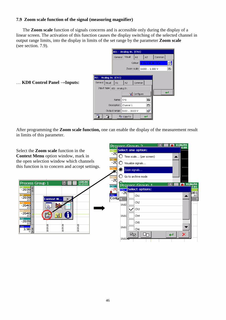
7.9 Zoom scale function of the signal (measuring magnifier)
The Zoom scale function of signals concerns and is accessible only during the display of a
linear screen. The activation of this function causes the display switching of the selected channel in
output range limits, into the display in limits of the set range by the parameter Zoom scale
(see section. 7.9).
… KD8 Control Panel →Inputs:
After programming the Zoom scale function, one can enable the display of the measurement result
in limits of this parameter.
Select the Zoom scale function in the
Context Menu option window, mark in
the open selection window which channels
this function is to concern and accept settings.

47
The display switching of the measurement
result of selected channels follows on the view
in limits defined by the parameter Zoom scale
(Channel (n) Visual)
To enable the Zoom scale function, one must in the option window of the Context menu,
during the display of the linear screen, select again the function Zoom scale for signals and in the
Select options window, disable marked previously channels (through tapping the screen by a finger
in the given channel field ).
7.10 Selection of the measuring data file format (digital signature)
One can select the CSV data format or CSV with digital signature in the Archive and
Visualization Edited group (n) Common File format menu: CSV, CSV with digital
signature, Binary with digital signature.
Data stored in binary format can be reviewed only
in the KD Archive program (see section 9.4).
The digital signature in the “enciphered” information enabling to check the likelihood of stored data
in the “CSV with digital signature” or data stored in binary format “Binary with digital signature”.
After selecting the format of file storage “CSV with digital signature” at every defined number of
measurement series (data block), a 128 bit “digital signature” is stored in the file. Each, even an
incidental change of data will be signalled during the file check by the KD Check program
(see section 9.3).
Output range of the 3 th channel
3 th channel , Zoom scale is enabled
48
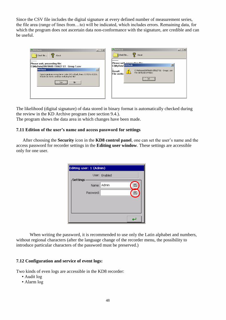
Since the CSV file includes the digital signature at every defined number of measurement series,
the file area (range of lines from…to) will be indicated, which includes errors. Remaining data, for
which the program does not ascertain data non-conformance with the signature, are credible and can
be useful.
The likelihood (digital signature) of data stored in binary format is automatically checked during
the review in the KD Archive program (see section 9.4.).
The program shows the data area in which changes have been made.
7.11 Edition of the user’s name and access password for settings
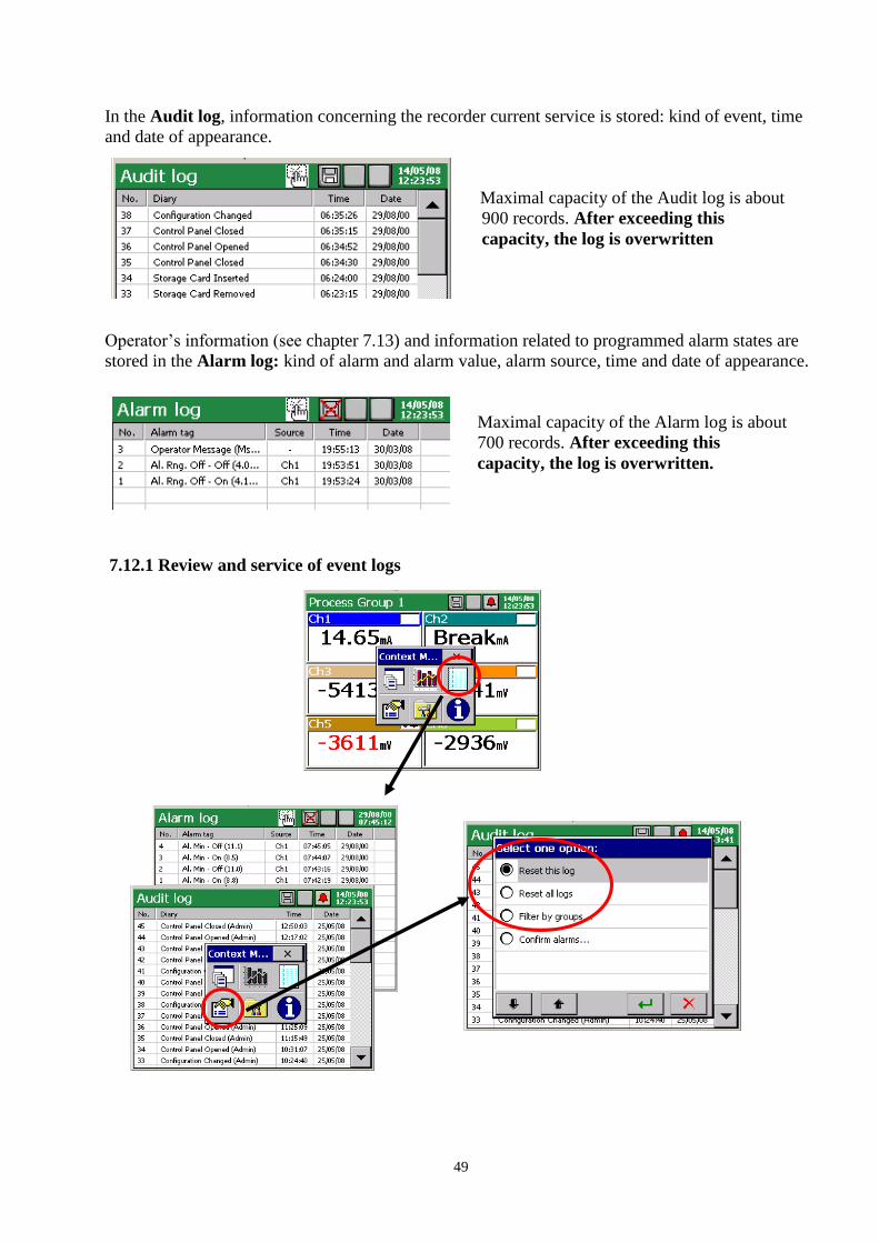
After choosing the Security icon in the KD8 control panel, one can set the user’s name and the
access password for recorder settings in the Editing user window. These settings are accessible
only for one user.
When writing the password, it is recommended to use only the Latin alphabet and numbers,
without regional characters (after the language change of the recorder menu, the possibility to
introduce particular characters of the password must be preserved.)
7.12 Configuration and service of event logs:
Two kinds of even logs are accessible in the KD8 recorder:
Audit log
Alarm log
49
In the Audit log, information concerning the recorder current service is stored: kind of event, time
and date of appearance.
Maximal capacity of the Audit log is about
900 records. After exceeding this
capacity, the log is overwritten
Operator’s information (see chapter 7.13) and information related to programmed alarm states are
stored in the Alarm log: kind of alarm and alarm value, alarm source, time and date of appearance.
Maximal capacity of the Alarm log is about
700 records. After exceeding this
capacity, the log is overwritten.
7.12.1 Review and service of event logs
50
After pressing the screen, during the visualization of measuring data, the Context menu is
displayed.
The pressure of the icon causes the view appearance of one of the event log and switching
the successive views of other logs.
The pressure of the icon during the review of one of the log causes the display, after the
previous confirmation of the user’s password (if it was programmed), the screen of the service
option of the given log: Reset this log / Reset all logs / Filter by groups, filtration of data related
to the selected group.
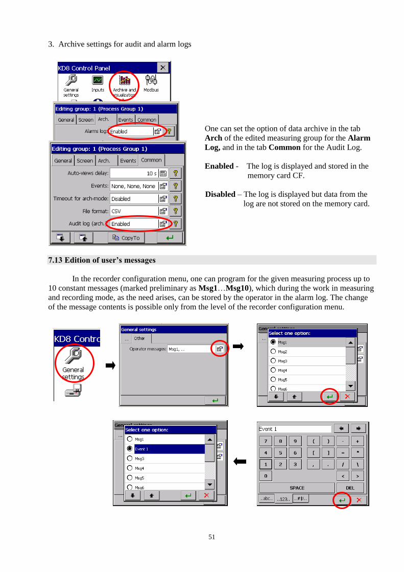
7.12.2 Programming of event logs
1. Setting of the last records number to logs (Audit and Alarm) shown on the recorder screen.
2. Setting the write of events in the alarm log (enabled/disabled)
A1 /A2/ in the tab of alarms of the analog input AI 1..6.
When selecting the record option: Disabled – messages will not appear in the log.
When selecting the record option: Enabled – messages will be displayed in the log.
51
3. Archive settings for audit and alarm logs
One can set the option of data archive in the tab
Arch of the edited measuring group for the Alarm
Log, and in the tab Common for the Audit Log.
Enabled - The log is displayed and stored in the
memory card CF.
Disabled – The log is displayed but data from the
log are not stored on the memory card.
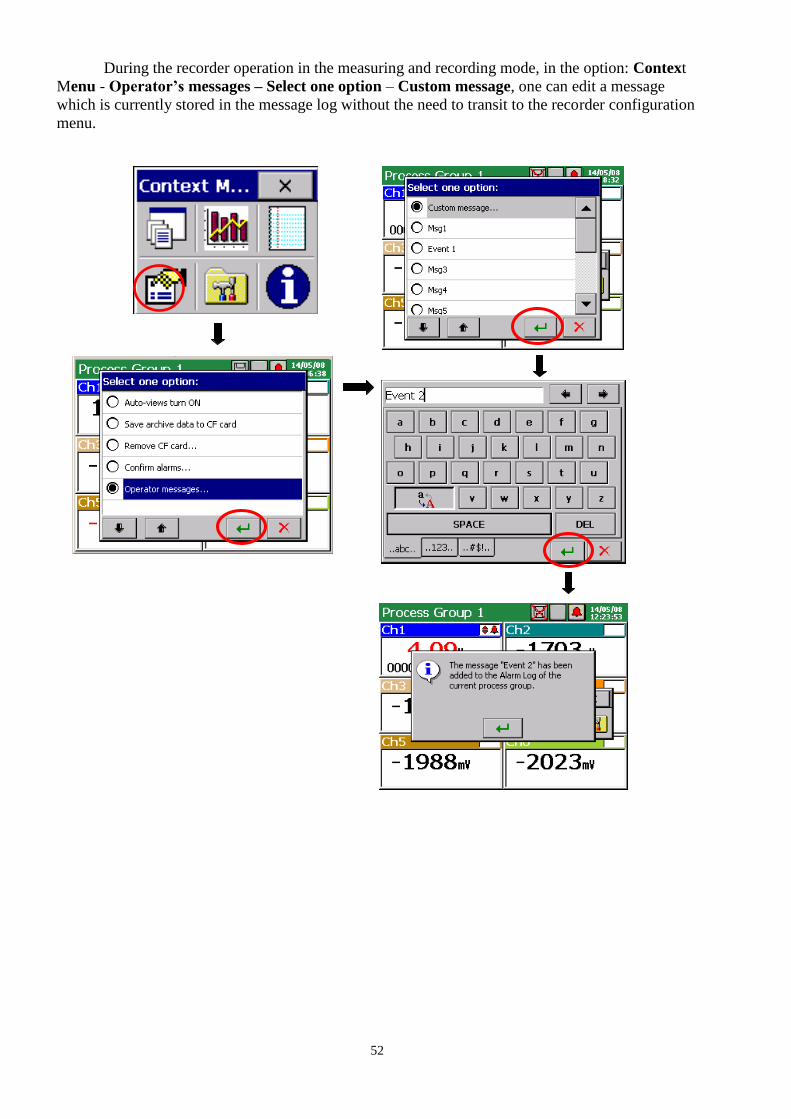
7.13 Edition of user’s messages
In the recorder configuration menu, one can program for the given measuring process up to
10 constant messages (marked preliminary as Msg1…Msg10), which during the work in measuring
and recording mode, as the need arises, can be stored by the operator in the alarm log. The change
of the message contents is possible only from the level of the recorder configuration menu.
52
During the recorder operation in the measuring and recording mode, in the option: Context
Menu - Operator’s messages – Select one option – Custom message, one can edit a message
which is currently stored in the message log without the need to transit to the recorder configuration
menu.
53
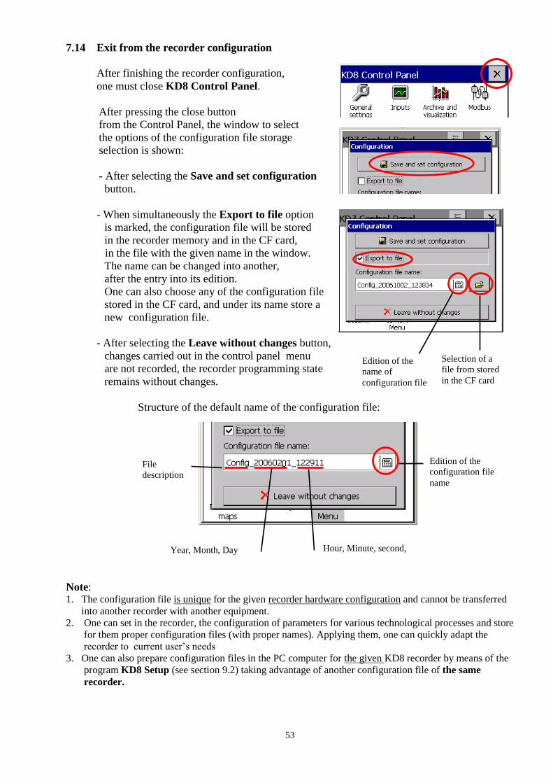
7.14 Exit from the recorder configuration
After finishing the recorder configuration,
one must close KD8 Control Panel.
After pressing the close button
from the Control Panel, the window to select
the options of the configuration file storage
selection is shown:
- After selecting the Save and set configuration
button.
- When simultaneously the Export to file option
is marked, the configuration file will be stored
in the recorder memory and in the CF card,
in the file with the given name in the window.
The name can be changed into another,
after the entry into its edition.
One can also choose any of the configuration file
stored in the CF card, and under its name store a
new configuration file.
- After selecting the Leave without changes button,
changes carried out in the control panel menu
are not recorded, the recorder programming state
remains without changes.
Structure of the default name of the configuration file:
Note: 1. The configuration file is unique for the given recorder hardware configuration and cannot be transferred
into another recorder with another equipment.
2. One can set in the recorder, the configuration of parameters for various technological processes and store
for them proper configuration files (with proper names). Applying them, one can quickly adapt the
recorder to current user’s needs
3. One can also prepare configuration files in the PC computer for the given KD8 recorder by means of the
program KD8 Setup (see section 9.2) taking advantage of another configuration file of the same
recorder.
Edition of the
configuration file
name
Year, Month, Day Hour, Minute, second,
File
description
Selection of a
file from stored
in the CF card
Edition of the
name of
configuration file
54
8. SELECTED ELEMENTS OF THE KD8 RECORDER CURRENT SERVICE
8.1 CompactFlash memory card
For the data storage in the KD8 recorder, one can use CompactFlash memory cards with a
capacity from 16 MB up to 4 GB. It is recommended to use CompactFlash cards from
SanDisk® company.
8.1.1 Information about the CF memory card.
After selecting in the KD8 Control Panel window, the icon in the
System information – CompactFlash tab, the information is given about the lack of the memory
card in the recorder or when it is inserted into the recorder, data about the current filling state of the
card, free place to store and total card capacity.
8.1.2 Formatting the CF card
After selecting the icon in the KD8 Control Panel, in the CompactFlash tab of the
General Settings window, one can choose options of formatting functions:
Quick format of CF card or Full format of CF card.
After confirming the selection, the formatting procedure of the CompactFlash memory card will
begin.

55
QUICK FORMAT OF THE PC CARD – deletes all files from the card, but does not scan
the card for damaged sectors. Quick formatting options must be selected when the card has
been already formatted and we have the certainty that it is not damaged.
FULL FORMAT OF THE CF CARD – deletes all files from the card and prepare the card
to store information in it. This is followed by the check of the actual card state, physical and
logic division of the card area into sectors, appropriate markings are given to them and a file
system is created.
During the CF card formatting, the LED diode on the frontal plate changes its color from
green into red .
8.1.3 Data storage on the CF memory card (card storage capacity)
During the recorder operation, when measuring data are stored in the recorder memory, the LED
diode placed on the KD8 frontal panel, lights in green. When data from the recorder memory are
reproduced on the CF card, the LED diode placed on the KD8 frontal plate changes the colour from
green into red.
During data recording on the CF card, one must not pull it out from the
recorder. The removal of the card can cause an irreversible loss of all
data stored on the memory card.
One can remove the card only after finishing the data storage on
it (green colour of the LED diode).
Data are stored on the CF card in successive files, each file has a capacity allowing to open in Excel
program. Files are generated separately for each channel group.
When introducing changes in the recorder configuration, all data from the buffer (stored in it at the
original configuration) are rewritten into the hereto open files of channel groups and new data,
obtained already after introducing changes in the configuration, are stored in new open files of
groups.
After exceeding 90% of the CF card capacity storage level (when the icon on the KD8 screen
has the red colour).
It is recommended to transfer data from the memory card to the PC computer as fast as possible,
format the card or replace for another, not recorded and formatted
LED diode

56
- Rough time of the full CF card storage
Depending on:
- rated CF card capacity
- parameters of data storage (storage period, number of groups, number of channels in the group,
data storage format: textual, binary).
Card
capacity
Number
of
groups
Number of
active
channels in
the group
Storage
period
Time of the card filling (hours/days)
Textual format Binary format
Hours Days Hours Days
512 MB 4 6
1 s 560 22 1800 76
5 s 2800 116 9200 380
10 s 5600 230 18000 760
1 min 33800 1400 110000 4600
1GB 4 6
1 s 1120 44 3600 152
5 s 5600 230 18400 760
10 s 11200 460 36000 1520
1 min 67600 2800 220000 9200
After exceeding the nominal capacity of the CF card, measuring data will be
stored in the KD8 buffer. During the data storage into the internal buffer,
one must replace the CF card by another, formatted card. If the card is not
replaced on time after filling the buffer, data will be overwritten.
The minimal working time of the recorder after which the buffer filling follows, is equal
ca 8.5 hours, for 2 measuring groups of 6 channels, each which a 1 sec. storage period.
Note: Using The Program KD Connect, one can copy data in the PC, from the
inserted CF card in the recorder and delete files.
During the recorder write, data from each measuring group are stored in the KD8 buffer.
Data are not currently recorded to the file in the CF card for the reason of possibility to a quick
damage of the card. The period of data recording from the given measuring group in the CF card is
the multiple of the programmed storage period for this group and can last even several months.
Considering that in the meantime, the access to the CF card with stored all current measuring data
on it is needed, before its extraction from the KD8 recorder, one must start the option
Save archive data to CF card – Then follows the rewrite of the current buffer contents on the CF
card. If there is the need, these data were automatically rewritten on the CF card, e.g. in the defined
interval of time then, one can apply the event Save data on CF.
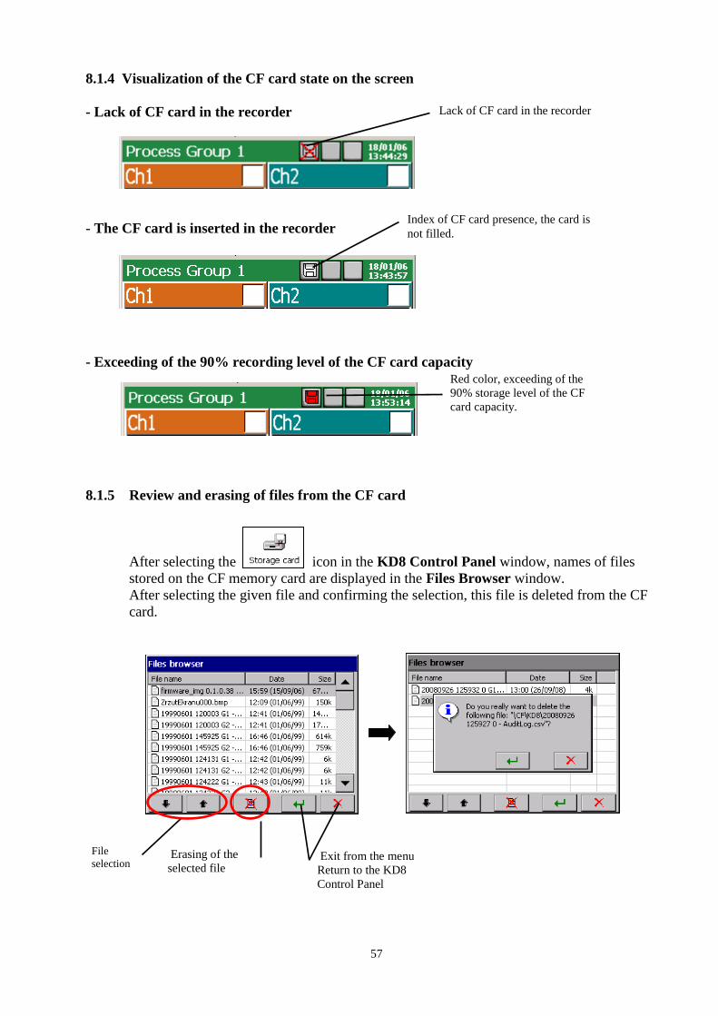
57
8.1.4 Visualization of the CF card state on the screen
- Lack of CF card in the recorder
- The CF card is inserted in the recorder
- Exceeding of the 90% recording level of the CF card capacity
8.1.5 Review and erasing of files from the CF card
After selecting the o icon in the KD8 Control Panel window, names of files
stored on the CF memory card are displayed in the Files Browser window.
After selecting the given file and confirming the selection, this file is deleted from the CF
card.
Lack of CF card in the recorder
Index of CF card presence, the card is
not filled.
Red color, exceeding of the
90% storage level of the CF
card capacity.
File
selection Erasing of the
selected file
Kasowanie
wybranego pliku
Exit from the menu
Return to the KD8
Control Panel

58
If the card is not inserted into the recorder or is
not formatted, a message informing about its
lack is displayed
8.1.6 Removal/replacement of the CF card, storage of archive data
In order to take out safely the CF card from the recorder (without the loss of measuring data), one
must open the Context menu window, (by pressing the screen with a finger), press the
icon of the option selection in it, and mark Remove CF card in the Select one option
open window.
After selecting this option, the complement of data will be made
automatically on the card with new data assembled (stored) in
the internal buffer (it is not necessary to select the Save archive
data to CF before choosing the Remove CF card option) and
next, the storage on the card will be locked till the acceptation
time of the displayed message. Before the message acceptation,
one can replace the card for a new one.
The removal of a CF card without the previous execution of described
above procedures can cause the loss of all measuring data.
The option Save archive data to CF card forces the rewriting of the newest data from the recorder
internal memory (data buffer) on the CF card. After rewriting these archive data on the CF card, the
storage to the buffer follows acc. to current settings
Taking in consideration the guaranteed life time of the CF card by
its producer, it is not recommended to use too often the Archive
data write on the card.

59
8.2 Review of archived data
The review option menu of archive data stored in the buffer is available after switching the screen
view into linear in the Context Menu, opening the selection window of currently available options
and selecting Go to archive mode in it.
In the archive mode, after tapping the icon or the screen in any place, the Archive
review mode (arrows of slow and fast scrolling of the chart and the option icon for servicing
archive data).
Following archive servicing options are available in the Select one option window:
- selection of the time scale for the archive chart,
- selection of visualized channels on the archive screen,
- enabled/disabled Zoom scale parameter (set up in the menu: …KD8 Control Panel→Inputs
– Channel 1..14 →Visual →Zoom scale )
- setting of time stamp parameters on the archive screen,
- enabled/disabled sampling points ( - points corresponding to the data storage time )
- end of the archive review and exit to the visualization window of current measuring data.
Fast/slow scrolling of the
screen in relation to set up
time stamp.
Opening of option
window for
archive service
Time
stamp
Archive
review mode
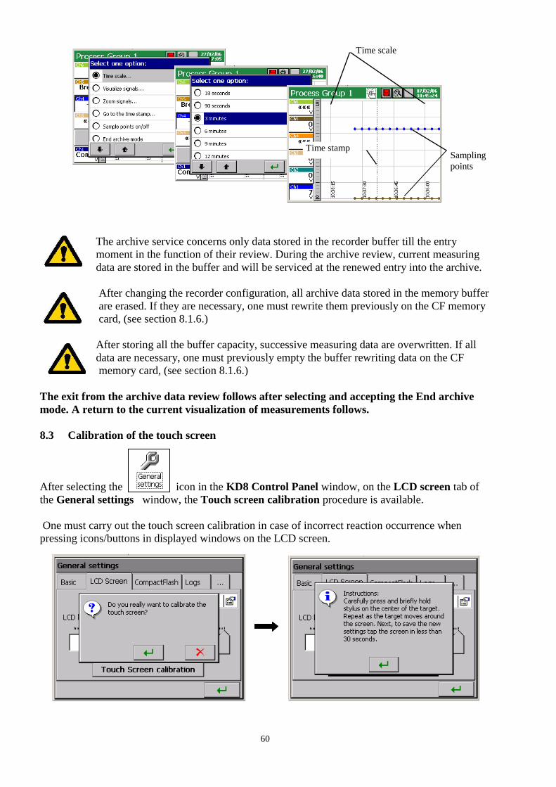
60
The archive service concerns only data stored in the recorder buffer till the entry
moment in the function of their review. During the archive review, current measuring
data are stored in the buffer and will be serviced at the renewed entry into the archive.
After changing the recorder configuration, all archive data stored in the memory buffer
are erased. If they are necessary, one must rewrite them previously on the CF memory
card, (see section 8.1.6.)
After storing all the buffer capacity, successive measuring data are overwritten. If all
data are necessary, one must previously empty the buffer rewriting data on the CF
memory card, (see section 8.1.6.)
The exit from the archive data review follows after selecting and accepting the End archive
mode. A return to the current visualization of measurements follows.
8.3 Calibration of the touch screen
After selecting the icon in the KD8 Control Panel window, on the LCD screen tab of
the General settings window, the Touch screen calibration procedure is available.
One must carry out the touch screen calibration in case of incorrect reaction occurrence when
pressing icons/buttons in displayed windows on the LCD screen.
Sampling
points
Time stamp
Time scale
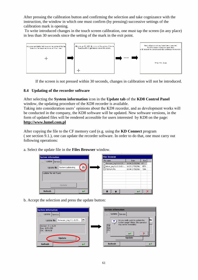
61
After pressing the calibration button and confirming the selection and take cognizance with the
instruction, the window in which one must confirm (by pressing) successive settings of the
calibration mark is opening.
To write introduced changes in the touch screen calibration, one must tap the screen (in any place)
in less than 30 seconds since the setting of the mark in the exit point.
If the screen is not pressed within 30 seconds, changes in calibration will not be introduced.
8.4 Updating of the recorder software
After selecting the System information icon in the Update tab of the KD8 Control Panel
window, the updating procedure of the KD8 recorder is available.
Taking into consideration users’ opinions about the KD8 recorder, and as development works will
be conducted in the company, the KD8 software will be updated. New software versions, in the
form of updated files will be rendered accessible for users interested by KD8 on the page:
http://www.lumel.com.pl
After copying the file to the CF memory card (e.g. using the KD Connect program
( see section 9.1.), one can update the recorder software. In order to do that, one must carry out
following operations:
a. Select the update file in the Files Browser window.
b. Accept the selection and press the update button:
….

62
b. After confirming the selection, the update begins and after its end, a message confirming its
fulfilment is displayed.
Recorder's configuration is converted automatically after updating firmware (by saving
automatically to file before update and automatically restoring it from file after update).
During the system update, one must not turn the recorder off and must not
take the CompactFlash out.
8.5 Service of data stored on the CF card, visualization
Measuring data, separately for each group of channels, are stored in textual files *.CSV with or
without the digital signature or in binary format with digital signature (see section 8.3). To check
the digital signature in the data file, the KD Check program is destined (see section 9.3.).
The likelihood (digital signature) of data stored in the binary format is automatically
checked during their scrolling and visualization in the KD Archive program (see section 9.4)
The limitation of the file capacity to 8 MB enables the direct review and visualization of data stored
in the textual format *.CSV, e.g. in the Excel program or OpenOffice Calc.
Data from the memory card can be recopied to a PC computer using the memory card reader
servicing cards of CompactFlash type or taking advantage from features of the KD Connect
program added to each delivered recorder.
The KD Connect program is destined for the communication between the PC computer and the
KD-Series recorder by means of the USB interface. It enables to carry out the following operations:
1) copying files from the CompactFlash card, directly from the recorder on the PC
computer (e.g. data files, screen dumps)
2) uploading of files from the PC computer on the CompactFlash card in the recorder
(e.g. file with the updated KD8 software)
ID of the logic channel
in the group G1

63
3) removal of accumulated files from the CompactFlash card in the recorder,
4) collection of current systemic information of the KD8 recorder (among others: system
version, current configuration, level of CompactFlash card fulfilling)
The KD8 Setup program (see section 9.2) enables to prepare in the PC a configuration file for the
KD8 recorder. The appearance and service of the KD8 Setup program are the same as to the
recorder service menu described in the user’s manual. But one must take notice of occurring
differences:
To service the KD8 Setup program, the mouse and computer keyboard are used.
Dialogues of file selection allow to review the contents of computer disks.
The language of the KD8 Setup program is compatible with the language of the last edited
configuration.
The appearance of dialogue windows highly depends on the system personalization (as e.g.:
the size of the system font).
The result of work with the KD8 Setup program is the configuration file for a recorder of a defined
hardware configuration (kind and number of cards, settlement of slots).
9. PROGRAMS ON PC
9.1 KD Connect Program
The KDConnect program is destined for the communication between the PC computer and the
KD-Series recorders by means of the USB interface.
The KD Connect program enables to carry out the following operations:
copying of files from the CompactFlash card, directly from the recorder into the PC
computer (e.g. data files, screen dumps),
uploading of files from the PC computer into the CompactFlash card in the recorder
(e.g. a file with the KD8 software update)
deletion of stored files in the recorder CompactFlash,
sampling of current systemic information of the KD8 recorder (among others, system
version, current configuration, degree of the CompactFlash filling)
9.1.1 Installation of drivers for the KD8 recorder
One must install the driver in order to see correctly the KD8 touch screen recorder under the
operating system MS Windows:
1. After connecting the recorder with the USB cable (delivered in the KD8 accessory set) to
the free port in the computer, information about the detection of a new hardware appears in
the computer.
Next, the creator to detect the new hardware will be started.
2. Please insert the CD disk delivered with the KD8 recorder into the CD-ROM drive.
3. (This point concerns the XP system with SP2) When asking: “Can the Windows system
be connected with the WEB page .....” mark the option “ No, not this time”
4. The dialogue “Creator of hardware updating” appears.
5. Select the option “Install the software automatically” and click “Next”.
6. Select the found driver from the list and press “Next” to install the driver by the creator.
When the creator inform about the lack of driver compatibility tests with Windows, answer
“Continue…”. Next, click the button “End”.

64
After the correct driver installation (a restart of the system is not required) one can transit to the
installation of the program delivered with the KD8 screen recorder.
Select the directory with the KDConnect program on the accompanied CD and start the
KDConnect_install.exe program. The program installation creator will be started. One must
proceed in compliance with instructions displayed on the screen.
9.1.2 Installation of the KD Connect program
Program requirements:
Operating system: MS Windows 2000 or a newest one,
Installed dedicated drivers for KD8 recorders,
About 3 MB of free capacity in the hard disk,
Other requirements equal to requirements makes demands of the operating systems
The program installation is typical for applications destined for the MS Windows environment. The
program installation is in the annexed CD disk, in the “KD Connect” directory.
To begin the installation, one must start the Setup program being in the indicated directory.
After selecting the language used during the installation, the window of the installation creation is
opening.
Next, proceed acc. to appearing messages on the screen.
After carrying out the installation, a window appears informing about its end.
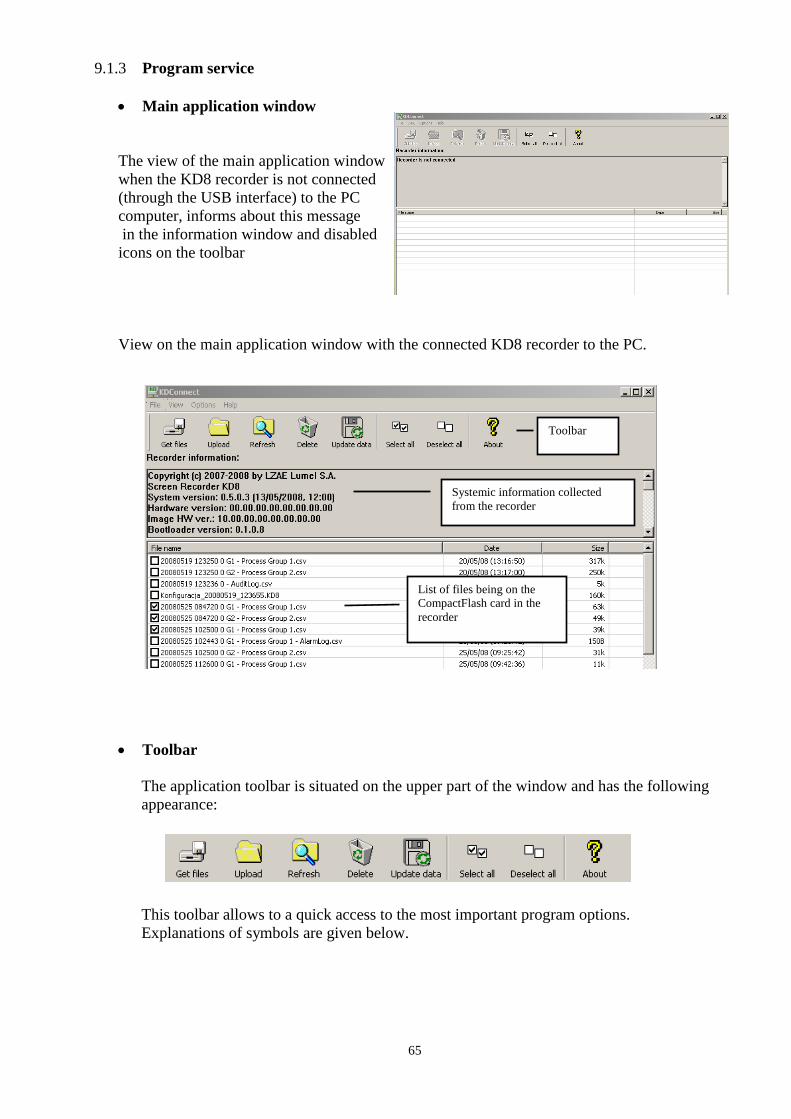
65
9.1.3 Program service
Main application window
The view of the main application window
when the KD8 recorder is not connected
(through the USB interface) to the PC
computer, informs about this message
in the information window and disabled
icons on the toolbar
View on the main application window with the connected KD8 recorder to the PC.
Toolbar
The application toolbar is situated on the upper part of the window and has the following
appearance:
This toolbar allows to a quick access to the most important program options.
Explanations of symbols are given below.
List of files being on the
CompactFlash card in the
recorder
Toolbar
Systemic information collected
from the recorder
66
Call of the collection option of marked files from the recorder into the
PC computer.
Upload the file from the PC computer into the CompactFlash installed
in the recorder.
Renewed collection of basic data from the recorder (systemic
information and the list of files).
Removal of marked files from the CompactFlash card installed in the
recorder.
Storage of all current measuring data from the buffer into CF
Selects all files on the list of files
Deselects all files on the list of files
Shows the program information window.
Program settings (Application menu Options Settings... )
Program options allow to change the application language. The selection of the language as
Default means the application start in the language consistent with the language of the
operating system if it is serviced by this program. Otherwise, the language of the application
is English.
Collecting function of files from the recorder (Application menu files Collect
marked files... )
To collect defined files from the recorder, one must mark them on the list of files (in the
square, next to the file name, the tick of marking appears).

67
Next, one must call the option Get selected files.... from the application menu.
or from the toolbar:
The window appears with the selection of the path for files recording in the PC computer:
After confirming the in-coming path, the copying of files begins.
To collect the defined file and start it with a default servicing program, one can click twice
on the file name.
The function of uploading files to the recorder ( Application menu Files Upload
files ...) .
The option allows to upload any file from the PC computer into the CompactFlash card installed
in the recorder. The command can be selected from the application menu.
or from the toolbar:
Marked file for
collecting
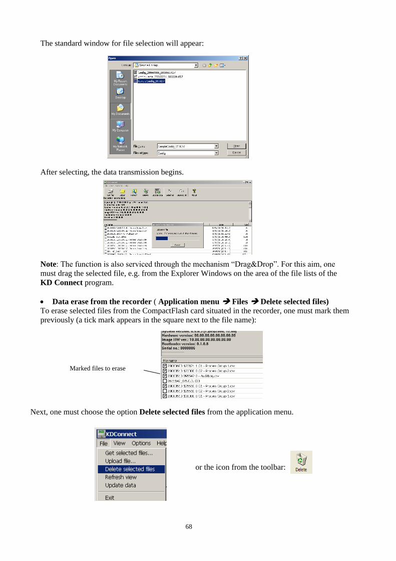
68
The standard window for file selection will appear:
After selecting, the data transmission begins.
Note: The function is also serviced through the mechanism “Drag&Drop”. For this aim, one
must drag the selected file, e.g. from the Explorer Windows on the area of the file lists of the
KD Connect program.
Data erase from the recorder ( Application menu Files Delete selected files)
To erase selected files from the CompactFlash card situated in the recorder, one must mark them
previously (a tick mark appears in the square next to the file name):
Next, one must choose the option Delete selected files from the application menu.
or the icon from the toolbar:
Marked files to erase
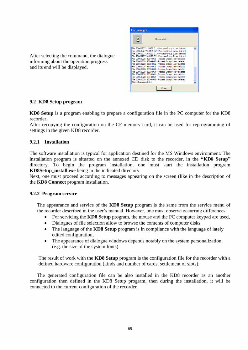
69
After selecting the command, the dialogue
informing about the operation progress
and its end will be displayed.
9.2 KD8 Setup program
KD8 Setup is a program enabling to prepare a configuration file in the PC computer for the KD8
recorder.
After recopying the configuration on the CF memory card, it can be used for reprogramming of
settings in the given KD8 recorder.
9.2.1 Installation
The software installation is typical for application destined for the MS Windows environment. The
installation program is situated on the annexed CD disk to the recorder, in the “KD8 Setup”
directory. To begin the program installation, one must start the installation program
KD8Setup_install.exe being in the indicated directory.
Next, one must proceed according to messages appearing on the screen (like in the description of
the KD8 Connect program installation.
9.2.2 Program service
The appearance and service of the KD8 Setup program is the same from the service menu of
the recorder described in the user’s manual. However, one must observe occurring differences:
For servicing the KD8 Setup program, the mouse and the PC computer keypad are used,
Dialogues of file selection allow to browse the contents of computer disks,
The language of the KD8 Setup program is in compliance with the language of lately
edited configuration,
The appearance of dialogue windows depends notably on the system personalization
(e.g. the size of the system fonts)
The result of work with the KD8 Setup program is the configuration file for the recorder with a
defined hardware configuration (kinds and number of cards, settlement of slots).
The generated configuration file can be also installed in the KD8 recorder as an another
configuration then defined in the KD8 Setup program, then during the installation, it will be
connected to the current configuration of the recorder.

70
- On the KD8 recorder side
a. Record the current KD8 configuration file on the CompactFlash card
Mark the option Export to file in the output dialogue from the KD8 Control Panel and give
the appropriate name to the file (or remain the proposed name). Next, store the
configuration. (option: Save and set configuration)
b. Upload the recorded configuration file to the PC computer by means of one of the recorder
communication interfaces. One can do this by means of the USB interface program and the
KD8 Connect program (see section 9) or through the Ethernet interface.
- On the PC computer side
a. Start the KD8 Setup program, call the context menu (tap on the area of the recorder
screen), and next press the input icon in order to configure the recorder.
b. The logging dialogue appears. One must transit into the configuration dialogue.
c. During the first configuration, one can select the only available option: Open configuration
from file. The standard dialogue of the Windows system appears to open files. One must
select the previously saved configuration file.
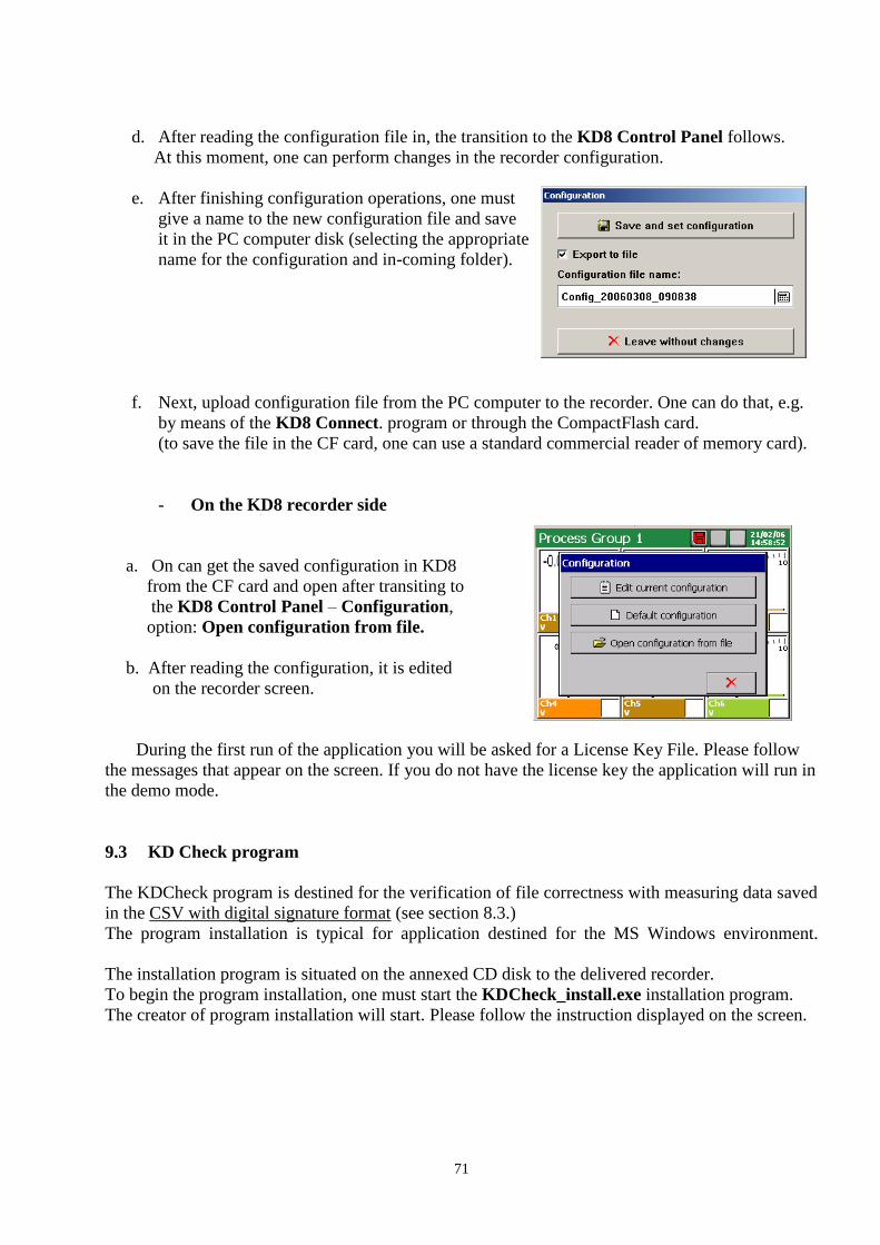
71
d. After reading the configuration file in, the transition to the KD8 Control Panel follows.
At this moment, one can perform changes in the recorder configuration.
e. After finishing configuration operations, one must
give a name to the new configuration file and save
it in the PC computer disk (selecting the appropriate
name for the configuration and in-coming folder).
f. Next, upload configuration file from the PC computer to the recorder. One can do that, e.g.
by means of the KD8 Connect. program or through the CompactFlash card.
(to save the file in the CF card, one can use a standard commercial reader of memory card).
- On the KD8 recorder side
a. On can get the saved configuration in KD8
from the CF card and open after transiting to
the KD8 Control Panel – Configuration,
option: Open configuration from file.
b. After reading the configuration, it is edited
on the recorder screen.
During the first run of the application you will be asked for a License Key File. Please follow
the messages that appear on the screen. If you do not have the license key the application will run in
the demo mode.
9.3 KD Check program
The KDCheck program is destined for the verification of file correctness with measuring data saved
in the CSV with digital signature format (see section 8.3.)
The program installation is typical for application destined for the MS Windows environment.
The installation program is situated on the annexed CD disk to the delivered recorder.
To begin the program installation, one must start the KDCheck_install.exe installation program.
The creator of program installation will start. Please follow the instruction displayed on the screen.
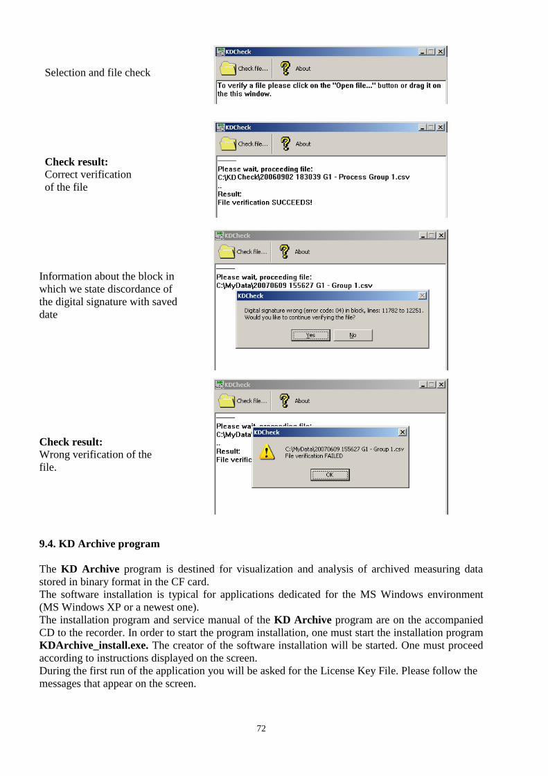
72
Selection and file check
Check result:
Correct verification
of the file
Information about the block in
which we state discordance of
the digital signature with saved
date
Check result:
Wrong verification of the
file.
9.4. KD Archive program
The KD Archive program is destined for visualization and analysis of archived measuring data
stored in binary format in the CF card.
The software installation is typical for applications dedicated for the MS Windows environment
(MS Windows XP or a newest one).
The installation program and service manual of the KD Archive program are on the accompanied
CD to the recorder. In order to start the program installation, one must start the installation program
KDArchive_install.exe. The creator of the software installation will be started. One must proceed
according to instructions displayed on the screen.
During the first run of the application you will be asked for the License Key File. Please follow the
messages that appear on the screen.

73
10. TECHNICAL DATA
Programmable measuring system: - number of measuring channels: 3 or 6
- input resistance 10 M (U, TC); =100 (I)
- sampling rate 350 ms (for 1 measuring place)
- measuring accuracy according to the table 1
- additional measuring error with the ≤ 1ºC
automatic temperature compensation
of the thermocouple reference cold junctions
- isolation between measuring places 100 V d.c.
- isolation measuring place-housing 500 V d.c.
Measuring ranges (universal measuring inputs) / Measuring accuracy:
Table 1
Input signal Signal symbol
in the menu
Measuring range /
Measuring accuracy (%)
Minimal sub-range /
Measuring accuracy (%)
1 2 3 4 5 6
Voltage mV 0... ± 9999 mV 0.15 5 mV 0.25
Current mA 0...±20 mA 0.15 1 mA 0.25
Thermocouple (TC): J ( Fe - CuNi )1) TC J -200...1200 C 0.1 100 C 1
K ( NiCr - NiAl ) 1) TC K - 200...1370 C 0.1 130 C 0.7
N (NiCrSi – Ni Si) 1) TC N -200...1300 C 0.1 200 C 0.5
E (NiCr-CuNi) 1) TC E -200...1000 C 0.1 100 C 1
R ( PtRh13 - Pt ) 1) TC R 0...1760 C 0.2 540 C 0.3
S ( PtRh10 - Pt ) 1) TC S 0...1760 C 0.2 570 C 0.3
T ( Cu- CuNi ) 1) TC T -200...400 C 0.1 110 C 0.9
B ( PtRh30 – PtRh6 ) 1) TC B 400…1820 C 0.2 1000 C 0.3
L (GOST) 2) TC TXK(GOST) -200 800 0.1 90 C 0.3
K (GOST) 2) TC TXA(GOST) -200 1370 0.1 130 C 0.7
Resist. thermometer (RTD): Pt 100 3) Pt 100 - 200...850 C 0.15
50 C
0.25
Pt 5003) Pt 500 - 200...850 C 0.3 0.5
Pt 10003) Pt 1000 - 200...850 C 0.3 0.5
Ni 1003) Ni 100 - 60...180 C 0.15 0.25
Ni 90,26 Ni 90,26 (P1) - 50...150 C 0.15 0.25
Cu 1003) Cu 100 -50...180 C 0.15 0.25
GR.21(GOST’78) 4) GR.21(GOST’78) -260…1100 C 0.15 0.25 GR.21 (GOST’94) 5) GR.21 (GOST’94) -260…1100 C 0.15 0.25 50P (GOST’78) 4) 50P (GOST’78) -260…1100 C 0.15 0.25 50P (GOST’94) 5) 50P (GOST’94) -260…1100 C 0.15 0.25 100P (GOST’78) 4) 100P (GOST’78) -260…1100 C 0.15 0.25
100P (GOST’94) 5) 100P (GOST’94) -200…200C 0.15 0.25 50M (GOST’78) 4) 50M (GOST’78) -200…200C 0.15 0.25 50M (GOST’94) 5) 50M (GOST’94) -200…200C 0.15 0.25 100M (GOST’78) 4) 100M (GOST’78) -200…200C 0.15 0.25 100M (GOST’94) 5) 100M (GOST’94) -200…200C 0.15 0.25
Potentiometric transmitter Pot. Trans. 0...2000 0.15 100 0.25
Resistance transmitter Res. Trans. 0...2000 0.15 100 0.25
1) Characteristics of thermocouples: acc. to EN 60584-1
2) Characteristics of thermocouples: acc. to GOST R 8.585-2001
3) Characteristics of resistance thermometers: acc. to EN 60751+A2
4) Characteristics of resistance thermometers: acc. to GOST 6651-78
5) Characteristics of resistance thermometers: acc. to GOST 6651-94
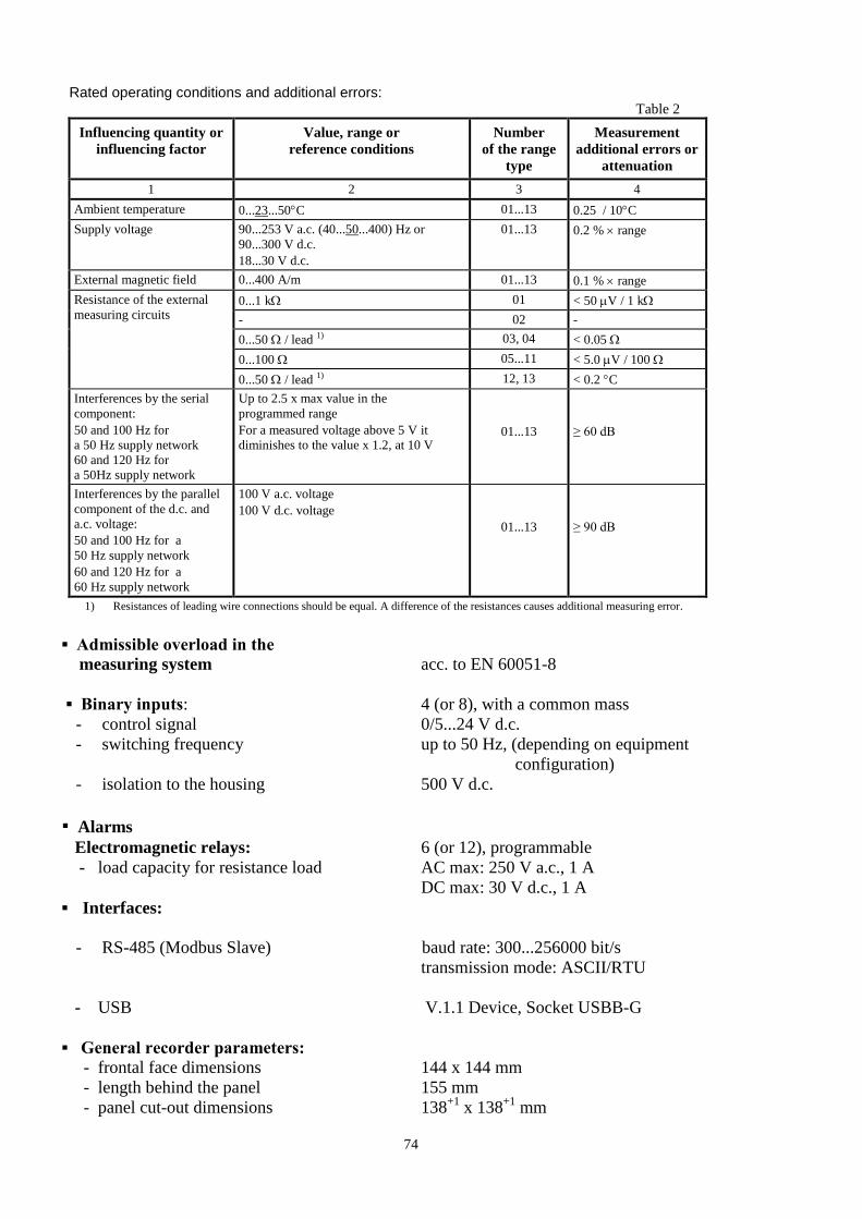
74
Rated operating conditions and additional errors:
Table 2
Influencing quantity or
influencing factor
Value, range or
reference conditions
Number
of the range
type
Measurement
additional errors or
attenuation
1 2 3 4
Ambient temperature 0...23...50C 01...13 0.25 / 10C
Supply voltage 90...253 V a.c. (40...50...400) Hz or
90...300 V d.c.
18...30 V d.c.
01...13 0.2 % range
External magnetic field 0...400 A/m 01...13 0.1 % range
Resistance of the external
measuring circuits 0...1 k 01 < 50 V / 1 k
- 02 -
0...50 / lead 1) 03, 04 < 0.05
0...100 05...11 < 5.0 V / 100
0...50 / lead 1) 12, 13 < 0.2 C
Interferences by the serial
component:
50 and 100 Hz for
a 50 Hz supply network
60 and 120 Hz for
a 50Hz supply network
Up to 2.5 x max value in the
programmed range
For a measured voltage above 5 V it
diminishes to the value x 1.2, at 10 V
01...13
≥ 60 dB
Interferences by the parallel
component of the d.c. and
a.c. voltage:
50 and 100 Hz for a
50 Hz supply network
60 and 120 Hz for a
60 Hz supply network
100 V a.c. voltage
100 V d.c. voltage
01...13
≥ 90 dB
1) Resistances of leading wire connections should be equal. A difference of the resistances causes additional measuring error.
Admissible overload in the
measuring system acc. to EN 60051-8
Binary inputs: 4 (or 8), with a common mass
- control signal 0/5...24 V d.c.
- switching frequency up to 50 Hz, (depending on equipment
configuration)
- isolation to the housing 500 V d.c.
Alarms
Electromagnetic relays: 6 (or 12), programmable
- load capacity for resistance load AC max: 250 V a.c., 1 A
DC max: 30 V d.c., 1 A
Interfaces:
- RS-485 (Modbus Slave) baud rate: 300...256000 bit/s
transmission mode: ASCII/RTU
- USB V.1.1 Device, Socket USBB-G
General recorder parameters:
- frontal face dimensions 144 x 144 mm
- length behind the panel 155 mm
- panel cut-out dimensions 138+1
x 138+1
mm
75
- weight ca. 2 kg
- tightening value of recorder
mounting brackets 0.2 Nm
- colour graphical screen LCD 5.7” of TFT type, 320 x 240 pixels
with a touch screen
- external data carrier CompactFlash up to 4GB
- memory of the internal buffer (flash) 6 MB
- working temperature 0...23...50 ºC
- related air humidity < 75% (without condensation)
- supply voltage 90...230...253 V a.c.
Power consumption (max) < 30 VA
Housing protection class:
- from frontal side IP65, acc. to EN 60529
- from terminal side IP20, acc. to EN 60529
Operational safety: acc. to EN 61010-1
- installation category II
- pollution level 2
Electromagnetic compatibility:
- noise emissions acc. to EN 61000-6-4
- noise immunity acc. to EN 61000-6-2

76
11. ORDER CODES
SCREEN RECORDER KD8 - X X X X XX X Measuring inputs: 3 programmable measuring inputs 1
6 programmable measuring inputs 2
Alarms and measuring inputs: without alarms and binary inputs 0
alarms + binary inputs 1) 1
Supply: 90...253V a.c., 90...300 V 1
18...30 V d.c. 2
Programs to service the recorder from a PC: Programs: KD Connect, KD Check 1
Programs: KD Connect, KD Check, KD Archive, KD8 Setup 2
Executions: standard 00
custom-made 2) XX
Acceptance tests: without an extra quality inspection certificate 8
with an extra quality inspection certificate 7
with calibration certificate 4
according to user’s agreemenets X
1) For each 3 measuring inputs, a package with 6 alarms and 4 binary inputs is installed.
2) After agreeing with the manufacturer
Accessories:
- 4 GB CF card ...............................0923-611-191
77
12. MAINTENANCE AND GUARANTEE
The KD8 recorder does not require any periodical maintenance.
In case of some incorrect operations:
1. After the dispatch date and within the period stated in the guarantee card
One should return the instrument to the Manufacturer’s Quality Inspection Dept.
If the instrument has been used in compliance with the instructions, the
Manufacturer warrants to repair it free of charge.
The disassembling of the housing causes the cancellation of the granted guarantee.
2. After the guarantee period:
One should send the instrument to repair it in an authorized service workshop.
Spare parts are available for the period of five years from the date of purchase.
Our policy is one of continuous improvement and we reserve the
right to make changes in design and specifications of any products
as engineering advances or necessity requires and revise the above
specifications without notice.

78
KD8-09G/1