ysi i n c o r p o r a t e d - equipco: rentals, sales, … · ysi i n c o r p o r a t e d ysi model...
TRANSCRIPT

YSI i n c o r p o r a t e d
YSI MODEL 6500YSI MODEL 6500YSI MODEL 6500YSI MODEL 6500 Environmental Process MonitorEnvironmental Process MonitorEnvironmental Process MonitorEnvironmental Process Monitor Operations Manual


i
CONTENTSCONTENTSCONTENTSCONTENTS
Page Section 1 INTRODUCTION 1 1.1 6500 Monitor Features 1 1.2 How to Use This Manual 2 Section 2 INSTALLATION 3 2.1 Unpacking and Inspection 3 2.2 Selecting an Installation Location 3 2.3 Installing the Sonde 7 2.4 Installing the 6500 Monitor 9 2.5 Wiring Instructions 11 2.5.1 Sonde Connections 11 2.5.2 AC Power Connections 13 2.5.3 Relays and Output Wiring 14 2.5.4 Grounding Information 15 2.5.5 Safety Issues 15 2.5.6 Lightning and Surge Protection 15 2.6 Sealants, Desiccant and Securing the Monitor 16 2.7 Installation Check List 17 Section 3 SYSTEM SETUP 19 3.1 System Configuration 19 3.2 6-Series Sonde Setup 20 3.3 6500 Monitor Setup 23 3.3.1 Calibration setup 24 3.3.2 Display setup 26 3.3.3 Relays 29 3.3.4 4-20 mA channel setup 31 3.3.5 Modbus Setup 32 3.3.6 Change Sonde Address 33 3.3.7 System Status 35 Section 4 CALIBRATION 37 4.1 General Calibration Tips 37 4.2 Field Calibration Using the 6500 Monitor 40 4.3 6500 calibration Warning and Error Messages 42 Section 5 PROPER USE AND CARE OF THE 6500 MONITOR SYSTEM 43 5.1 Deciding How to Use Your Monitoring System 43 5.2 Quality Assurance 47 5.2.1 Sonde Maintenance and Deployment Site 48 5.2.2 Calibration Checks 49 5.2.3 Recommended Quality Assurance Protocol 49 5.2.4 Recommended Monthly Maintenance of DO Probe 51 5.2.5 Recommended Cleaning of the 6500 Enclosure 52

ii
Section 6 TROUBLESHOOTING 53 6.1 Communication Problems 53 6.2 6500 Menu Choice Problems 55 6.3 Calibration Error Messages 56 6.4 Sensor Accuracy and Repeatability Problems 56 6.5 Alarm Function Problems 57 6.6 4-20 mA Loop Output Problems 58 Section 7 WARRANTY AND SERVICE INFORMATION 59 Appendix A SPECIFICATIONS 63 Appendix B HEALTH AND SAFETY 65 Appendix C REQUIRED NOTICE 73 Appendix D ACCESSORIES 75 Appendix E SOLUBILITY AND PRESSURE/ALTITUDE TABLES 99 Appendix F ADVANCED CALIBRATION SETUP 103 Appendix G INDEX 105
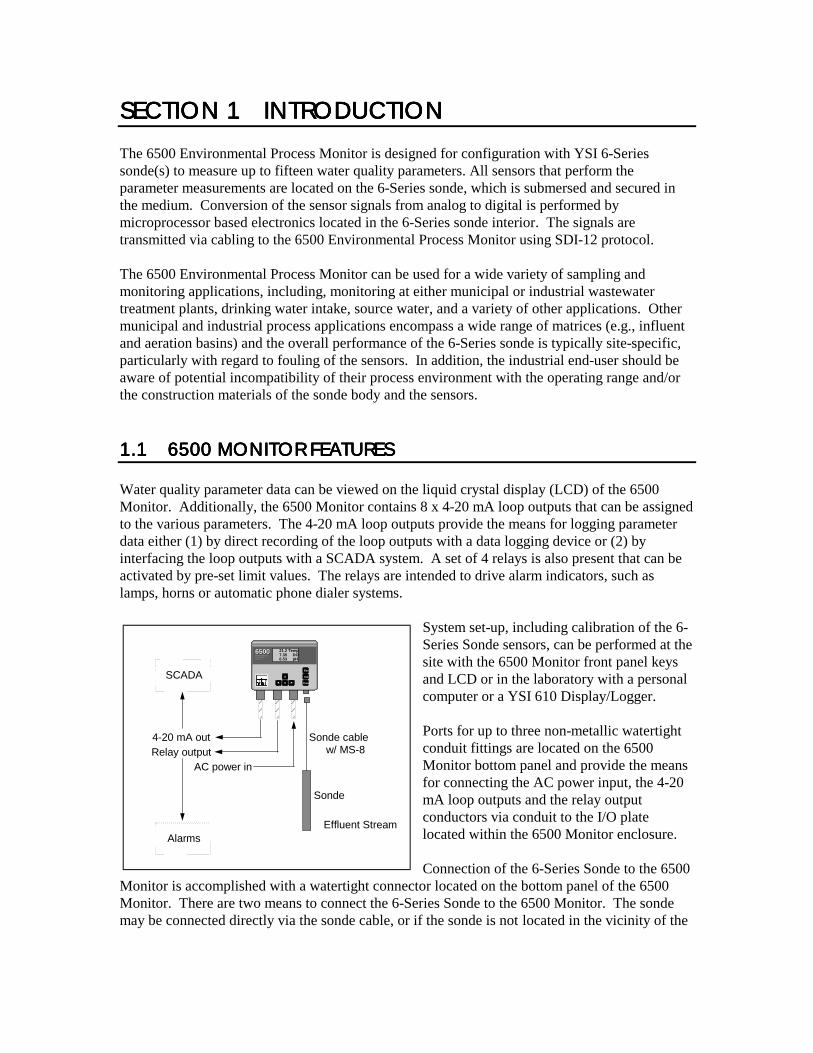
SECTION 1SECTION 1SECTION 1SECTION 1 INTRODUCTIINTRODUCTIINTRODUCTIINTRODUCTION ON ON ON The 6500 Environmental Process Monitor is designed for configuration with YSI 6-Series sonde(s) to measure up to fifteen water quality parameters. All sensors that perform the parameter measurements are located on the 6-Series sonde, which is submersed and secured in the medium. Conversion of the sensor signals from analog to digital is performed by microprocessor based electronics located in the 6-Series sonde interior. The signals are transmitted via cabling to the 6500 Environmental Process Monitor using SDI-12 protocol. The 6500 Environmental Process Monitor can be used for a wide variety of sampling and monitoring applications, including, monitoring at either municipal or industrial wastewater treatment plants, drinking water intake, source water, and a variety of other applications. Other municipal and industrial process applications encompass a wide range of matrices (e.g., influent and aeration basins) and the overall performance of the 6-Series sonde is typically site-specific, particularly with regard to fouling of the sensors. In addition, the industrial end-user should be aware of potential incompatibility of their process environment with the operating range and/or the construction materials of the sonde body and the sensors. 1.11.11.11.1 6500 MONITOR FEA6500 MONITOR FEA6500 MONITOR FEA6500 MONITOR FEATURESTURESTURESTURES Water quality parameter data can be viewed on the liquid crystal display (LCD) of the 6500 Monitor. Additionally, the 6500 Monitor contains 8 x 4-20 mA loop outputs that can be assigned to the various parameters. The 4-20 mA loop outputs provide the means for logging parameter data either (1) by direct recording of the loop outputs with a data logging device or (2) by interfacing the loop outputs with a SCADA system. A set of 4 relays is also present that can be activated by pre-set limit values. The relays are intended to drive alarm indicators, such as lamps, horns or automatic phone dialer systems.
System set-up, including calibration of the 6-Series Sonde sensors, can be performed at the site with the 6500 Monitor front panel keys and LCD or in the laboratory with a personal computer or a YSI 610 Display/Logger. Ports for up to three non-metallic watertight conduit fittings are located on the 6500 Monitor bottom panel and provide the means for connecting the AC power input, the 4-20 mA loop outputs and the relay output conductors via conduit to the I/O plate located within the 6500 Monitor enclosure. Connection of the 6-Series Sonde to the 6500
Monitor is accomplished with a watertight connector located on the bottom panel of the 6500 Monitor. There are two means to connect the 6-Series Sonde to the 6500 Monitor. The sonde may be connected directly via the sonde cable, or if the sonde is not located in the vicinity of the
Enter
Esc
Cal
65006500ENVIRONMEN TALENVIRONMEN TALMONITORINGMONITORINGSYSTE MSYSTE M
21.2 Temp7.35 DO6.53 pH
4-20 mA outRelay output
AC power in
Sonde cablew/ MS-8
Effluent Stream
Sonde
Alarms
SCADA
Introduction Section 1
YSI Incorporated 6500 Environmental Process Monitor 2
6500 Monitor installation, an optional YSI #6508 Junction Box may be used with customer-supplied cabling. With the optional Breakout Box (YSI #6504), the 6500 Environmental Process Monitor can be used with multiple sondes. The 6500 Monitor is designed for indoor or outdoor use, and features a watertight enclosure. An optional weather shield (YSI # 6505) is also available. Other optional accessories include several different mounting kits for the sondes and 6500 Monitor. See Appendix D, Accessories, for more information. 1.21.21.21.2 HOHOHOHOW TO USE THIS MANUALW TO USE THIS MANUALW TO USE THIS MANUALW TO USE THIS MANUAL The manual is organized to let you quickly understand how to install and operate the 6500 Monitor system. However, it cannot be stressed too strongly that informed and safe operation is more than just knowing which buttons to push. An understanding of the principles of operation, installation, calibration techniques, system setup and maintenance is necessary to obtain accurate and meaningful results. Before you begin to use the 6500 Environmental Process Monitor, it is strongly recommended that you thoroughly read and understand the YSI 6-Series Sonde Manual. The sonde manual will be referenced in several parts of the 6500 Manual. Before using the sonde with the 6500 Monitor, you must: ! Install the dissolved oxygen membrane ! Install the probes ! Learn how to access sonde software ! Calibrate the sensors ! Learn how to take readings If you are using multiple sondes, each sonde must have a different address (name) and each sonde must be named separately. Assigning the names are done by accessing the sonde software and entering System Setup from the Main Menu. From the System Setup, then enter SDI-12 Address. A character (0-9 and A-F) may be assigned to each sonde that you are using, but each sonde MUST have a different name. For more information about the other functions of the System Setup, see the 6-Series Sonde Operations Manual, Section 2. Included with this manual is a laminated Field Operation Guide that allows quick and convenient reference to 6500 operation, maintenance and troubleshooting at the installation site. This guide references sections of the basic manual when more detailed information is needed.

2.1 UNPACKING AND I2.1 UNPACKING AND I2.1 UNPACKING AND I2.1 UNPACKING AND INSPECTIONNSPECTIONNSPECTIONNSPECTION Inspect the outside of the shipping carton for damage. If damage is detected, contact the carrier immediately. Remove the instrument from the shipping container. Be careful not to discard any parts or supplies. Confirm that all items on the packing list are present. Inspect all assemblies and components for damage. The basic 6500 Environmental Process Monitor is shipped with the following major components. ! 6500 Monitor and mounting hardware ! 6506 Desiccant Kit ! 065926 Conduit Fittings (3) ! 065921 Industrial Encapsulant (sealer for conduit fittings) ! 065927 Knockout Plugs (2) ! 065902 Operations Manual ! 065979 Field Operation Guide If you ordered a 6-Series Sonde and/or reagents, these may be shipped separately. For optional accessories information see Appendix D, Accessories. If any parts are damaged or missing, contact your factory representative immediately. If you do not know from which dealer your 6500 Environmental Process Monitor was purchased, refer to Section 7, Warranty and Service Information. Check the monitor for any obvious external damage. Save the original packing cartons and materials. Carriers typically require proof of damage due to mishandling. Also, if it is necessary to return the monitor, you should pack the equipment in the same manner it was received. Once the system is installed and working, maintaining original cartons and packing material is less critical. If the monitor, sonde and associated components match the packing list and the components appear to be in satisfactory condition, proceed to the installation sections below.
WARNING! To avoid severe personal injury or damage to the equipment, installation, operation and service should be performed by qualified personnel who are thoroughly familiar with the entire contents of this manual.
2.2 SELECTING AN IN2.2 SELECTING AN IN2.2 SELECTING AN IN2.2 SELECTING AN INSTALLATION LOCATIONSTALLATION LOCATIONSTALLATION LOCATIONSTALLATION LOCATION The 6500 Monitoring System is an on-line continuous measurement tool that can provide valuable insight into your facility’s operation and performance. As with any instrument of this type, proper installation is the first important step to ensure you are provided with reliable
SECTION 2SECTION 2SECTION 2SECTION 2 INSTALLATIINSTALLATIINSTALLATIINSTALLATIONONONON

Installation Section 2
YSI Incorporated 6500 Environmental Process Monitor 4
performance and accurate data. Installation of the monitor and sonde should be carefully planned in advance to obtain the most effective and accurate utilization of the equipment. Two major components make up the 6500 Environmental Monitoring System: the 6500 Monitor and the 6-Series Sonde that contains the sensors. The sonde is a multi-parameter sensor device that must be placed in a representative sampling location to monitor desired water quality parameters in the flow stream. Since the 6500 Monitor may be located considerable distance from the sonde, a specialized Breakout box and/or Junction Box may be required for your installation, see Appendix D for Accessories information. See Figures 2 and 3 for diagrams of the two most common installation configurations.
CHOOSING A SONDE LOCCHOOSING A SONDE LOCCHOOSING A SONDE LOCCHOOSING A SONDE LOCATIONATIONATIONATION
The sonde installation will be determined by the site necessary to obtain water quality readings which are representative of the bulk flow stream. A suitable location should take a number of physical and chemical factors into consideration: # The sonde must be located in the flow stream where level fluctuations will not expose the
sensing probes to the atmosphere. The sonde sensors must remain submersed at all times during the monitoring.
# The sonde must be placed in a well mixed, free flowing area of the process stream. The flow
stream should be representative of the process flow being monitored. For example, if effluent flow is being analyzed, do not place the sonde ahead of a tank or an area that provides for extended detention time of the effluent desired for monitoring.
# Ideally, the sonde should be placed at least three (3) feet away from the sidewall and at least
two (2) feet submersed. For most flow channels, midstream and mid-depth would be the most representative area for the sonde location.
# Ideally, the sonde should be placed at an angle within 450 of vertical and directed with the
flow direction (see Figure 1). This location will provide for the least stress on the support arm holding the sonde while minimizing opportunity to collect debris. Placement against the flow stream or perpendicular to the flow stream also provides accurate monitoring, but inspection and cleaning may be required more frequently due to increased collection of debris.

Installation Section 2
YSI Incorporated 6500 Environmental Process Monitor 5
Figure 1 Sonde orientation
If the sonde is to be utilized in monitoring for results of chemical feeds and resulting chemical reactions, sufficient downstream mixing and reaction time should be provided prior to insertion of the sonde for monitoring. If pH adjustment is necessary, the sonde location should provide for sufficient mixing and reaction time upstream of the location. Thus, if you question the ideal location for monitoring, check your installation by manually testing upstream and downstream of the sondes proposed location. It may prove that you can utilize “less-than-ideal” sonde location in the flow stream, but take advantage of the location supports for mounting, proximity to the monitor or other factors that may facilitate the installation. The flow stream should be as free as possible of debris (e.g., algae) which could collect on the sonde and cause erroneous readings. Remember that this is an on-line device that is measuring actual conditions in real time. Composite sampling for pH, for example, will not match on-line monitoring. Therefore, pH values recorded by the chart recorder and/or plant control system connected to the 6500 Environmental Monitoring System cannot be averaged to equal the pH of the composite sample.
CHOOSING A MONITOR LCHOOSING A MONITOR LCHOOSING A MONITOR LCHOOSING A MONITOR LOCATIONOCATIONOCATIONOCATION
The sonde is a primary device that measures conditions in the flow stream and transmits a low voltage signal to the 6500 Monitor. The sonde is attached to a cable that is equipped with a “military grade” watertight connection to the monitor or optional breakout box. Several optional accessories are available from YSI to make the 6500 Monitor extremely versatile. The YSI #6502 Breakout Box is an enclosure for the connections interface between the sonde cable(s) and customer supplied wiring and conduit which enables the sensor connection to the monitor to be extended up to 250 feet. The YSI #6503 Breakout Box is the same as #6502, but is also CE compliant for European users. The YSI #6504 Breakout Box is similar to the above description, but can also handle two sondes. These Breakout Boxes makes it possible to install the monitor in a location and environment different than the sonde(s). A YSI #6508
Stream
SondeNot drawnto scale.
Installation Section 2
YSI Incorporated 6500 Environmental Process Monitor 6
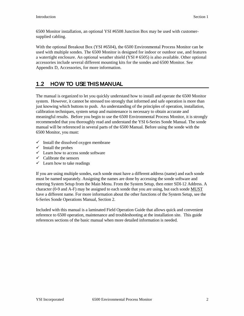
Junction Box is also needed if the 6500 Monitor is installed with multiple sondes, or if a single sonde is farther than 6 feet away. Note: The 6500 Monitor is provided with a weatherproof enclosure that will withstand most environmental conditions with no compromise to system performance. An optional Weather Shield (YSI #6505) is available for added protection from the elements. Figure 2 Monitor installed using sonde cable
Enter
Esc
Cal
65006500ENVIRONMENTALENVIRONMENTALMONITORINGMONITORINGSYSTE MSYSTE M
21.2 Temp7.35 DO6.53 pH
AC
Sonde
StreamNot drawn to scale.
6500 Monitor
Locating the monitor near the sonde will have advantages since in-situ (on-line) calibration can be more easily facilitated under this arrangement. For example, a recently calibrated, hand-held dissolved oxygen meter and probe can be placed next to the sonde and readings compared between the monitor and the hand-held meter. In addition, operator checks to verify accuracy and determine the frequency of calibration for water quality measurement in the flow stream can be easily carried out with a variety of hand-held manual readings at the time of inspection by the operator if the monitor is conveniently located. Two sondes, #6920 and #600XLM, have logging capability. These two sondes are able to store recorded data into their memory, which then can be downloaded into a PC or Display/Logger. If the 6500 cannot be connected to a system such as a SCADA, data can still be recorded using one of these two sondes. The 6500 itself does not record data; it only displays real-time monitoring.
Installation Section 2
YSI Incorporated 6500 Environmental Process Monitor 7
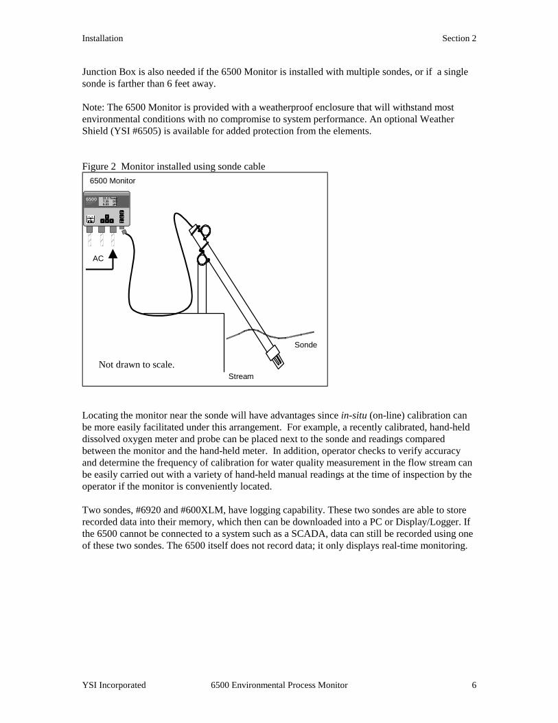
Figure 3 Remote location of monitor relative to sonde
Enter
Esc
Cal
65006500ENVIRONMENTALENVIRONMENTALMONITORINGMONITORINGSYSTE MSYSTE M
21.2 Temp7.35 DO6.53 pH
sonde cablew/ MS-8
Stream
Sonde
Breakout Box
Conduit &
65076’ Patch cable
w/ MS-8
customer-supplied3-conductor cable250’ Maximum
Junction Box 6508
6500 Monitor
Not drawn to scale.
AC
YSI also provides a means for convenient and accurate bench calibration of the sonde. Refer to the Sonde Manual for bench calibration procedures. Bench calibration allows the operator to easily disconnect the sonde from the monitor and then reconnect the sonde to a laboratory computer or terminal device (YSI 610 display/logger). Under this protocol, the sonde can be fully checked in a user-friendly environment, recalibrated and then redeployed. If the sonde is equipped with a bulkhead connector rather than an integral cable, bench calibration is used. If locating the monitor near the sonde is not possible due to environmental conditions and/or accessibility, bench calibration provides a very good alternative to on-line calibration. Although the monitor is suitable for outdoor use, it should be located in an area where temperature extremes, vibrations, electromagnetic and radio frequency interference are minimal. Select an installation location that is at least two (2) feet from any high voltage conduit. Avoid mounting on severely vibrating structures. Be sure the monitor can be fully opened and serviced at its installed location by maintenance personnel. Be sure the site has easy access for operating personnel.
2.32.32.32.3 INSTALLING THE SINSTALLING THE SINSTALLING THE SINSTALLING THE SONDEONDEONDEONDE After you have chosen suitable sites for the monitor and sonde, proceed with the installation as described below. Avoid routing sonde cabling near wiring associated with rotating machinery and/or equipment involving electrical switching or regulation. Consider placing sonde cabling in grounded metallic conduit if unstable readings appear due to electromagnetic interference.

Installation Section 2
YSI Incorporated 6500 Environmental Process Monitor 8
RAIL MOUNT OPTION RAIL MOUNT OPTION RAIL MOUNT OPTION RAIL MOUNT OPTION
The sonde can be mounted in a number of different configurations, but a rail mount with a fabricated bracket is recommended. A rail mount kit is also available from YSI, #6511 for 600 series sondes, and 6512 for 6820/6920 sondes. See Appendix D, Accessories for more information. Figures 4 and 5 show the two common connection layouts and short and long-range wiring of the monitor to the sonde. Figure 4 Direct connection
Enter
Esc
Cal
65006500ENVIRONMEN TALENVIRONMEN TAL
MONITORINGMONITORING
SYSTE MSYSTE M
21.2 Temp7.35 DO6.53 pH
4-20 mA outRelay output
AC power in
sonde cablew/ MS-8
Stream
Sonde
Alarms
SCADA
Installation Section 2
YSI Incorporated 6500 Environmental Process Monitor 9
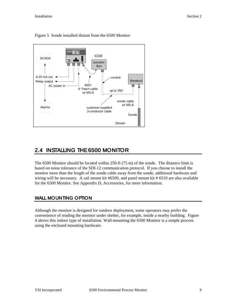
Figure 5 Sonde installed distant from the 6500 Monitor
2.4 INSTALLING THE 2.4 INSTALLING THE 2.4 INSTALLING THE 2.4 INSTALLING THE 6500 MONITOR6500 MONITOR6500 MONITOR6500 MONITOR The 6500 Monitor should be located within 250-ft (75 m) of the sonde. The distance limit is based on noise tolerance of the SDI-12 communication protocol. If you choose to install the monitor more than the length of the sonde cable away from the sonde, additional hardware and wiring will be necessary. A rail mount kit #6509, and panel mount kit # 6510 are also available for the 6500 Monitor. See Appendix D, Accessories, for more information.
WALL MWALL MWALL MWALL MOUNTING OPTION OUNTING OPTION OUNTING OPTION OUNTING OPTION
Although the monitor is designed for outdoor deployment, some operators may prefer the convenience of reading the monitor under shelter, for example, inside a nearby building. Figure 4 shows this indoor type of installation. Wall-mounting the 6500 Monitor is a simple process using the enclosed mounting hardware.
6508Enter
Esc
Cal
65006500ENVIRONMEN TALENVIRONMEN TALMONITORINGMONITORINGSYSTE MSYSTE M
21.2 Temp7.35 DO6.53 pH
4-20 mA outRelay output
AC power in
Junction Box
sonde cablew/ MS-8
Stream
Sonde
Breakout
up to 250 ‘
conduit
65076’ Patch cable
w/ MS-8
customer-supplied3-conductor cable
Alarms
SCADA
Installation Section 2
YSI Incorporated 6500 Environmental Process Monitor 10
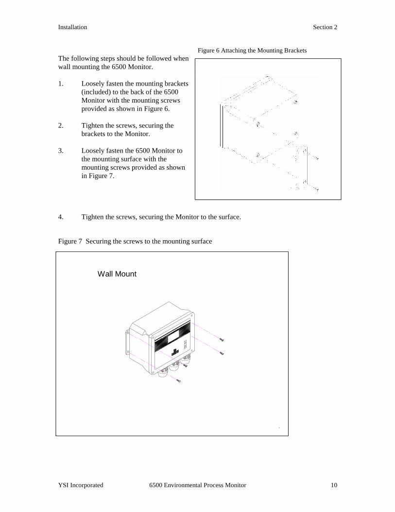
Figure 6 Attaching the Mounting Brackets The following steps should be followed when wall mounting the 6500 Monitor. 1. Loosely fasten the mounting brackets
(included) to the back of the 6500 Monitor with the mounting screws provided as shown in Figure 6.
2. Tighten the screws, securing the
brackets to the Monitor. 3. Loosely fasten the 6500 Monitor to
the mounting surface with the mounting screws provided as shown in Figure 7.
4. Tighten the screws, securing the Monitor to the surface. Figure 7 Securing the screws to the mounting surface
Wall Mount
Installation Section 2
YSI Incorporated 6500 Environmental Process Monitor 11
2.52.52.52.5 WIRING INSTRUCTIWIRING INSTRUCTIWIRING INSTRUCTIWIRING INSTRUCTIONSONSONSONS
WARNING! A qualified electrician should perform wiring.
Do not make connections while power is applied. Disconnect power before proceeding. This particular phase of the installation will vary considerably depending on the distance between the sonde and monitor and on which outputs you use in your particular configuration. In the simplest configuration in which the sonde is connected using the sonde cable and neither the relay outputs nor the 4-20 mA current loop outputs are used, only AC power wiring is required. The sonde connects to the monitor by the MS-8 sonde cable connector, which is pre-wired. The end connection of the cable is a military-style 8-pin connector (MS-8). If, however, the monitor is more than the length of the sonde cable away from the sonde and either of the outputs is wired to alarms or a SCADA system, additional wiring is required. Below are wiring instructions for all parts of the 6500 Environmental Process Monitoring system. The 6500 Monitor has one MS-8 connector and three conduit openings in the bottom of the monitor housing which will accommodate ¾ inch conduit fittings. From a front view, the 2 conduit openings on the left are for the four relay outputs and the eight 4-20 mA outputs. The conduit opening on the right should be used for the AC power supply cable. The MS-8 connector is used to interface with the sonde cable in the close range system layout, or in the long distance wiring layout, the optionally-supplied 6 foot (1.8 m) patch cable (YSI #6507) to the #6508 Junction Box. Refer back to Figure 3 to review the configuration options.
IMPORTANT! It is essential that all sensor wiring be run in a separate conduit from power wiring.
2.5.12.5.12.5.12.5.1 SONDE CABLE COSONDE CABLE COSONDE CABLE COSONDE CABLE CONNECTIONS (SDINNECTIONS (SDINNECTIONS (SDINNECTIONS (SDI----12 12 12 12 COMMUNICATIONS LINK)COMMUNICATIONS LINK)COMMUNICATIONS LINK)COMMUNICATIONS LINK)
The sonde is equipped with a detachable or non-detachable cable. This connector plugs directly into the 6500 Monitor when the 6500 Monitor is within range of the sonde cable. This configuration is shown in Figure 2. In remote sonde installations the 6500 Monitor uses a standard MS-8 connection to interface with the 6-ft (1.8 m) Patch Cable (YSI #6507) that will run to the #6508 Junction Box. The customer is advised to supply rigid conduit and 18 AWG or heavier shielded multi-conductor cable to connect between the local junction box and the remote 6502 Breakout Box at the sonde installation site. The cable from the Junction Box should be landed to TB-1 in the Breakout Box. The MS-8 connector for sonde hookup is pre-wired to TB-2 and TB-3.
Installation Section 2
YSI Incorporated 6500 Environmental Process Monitor 12
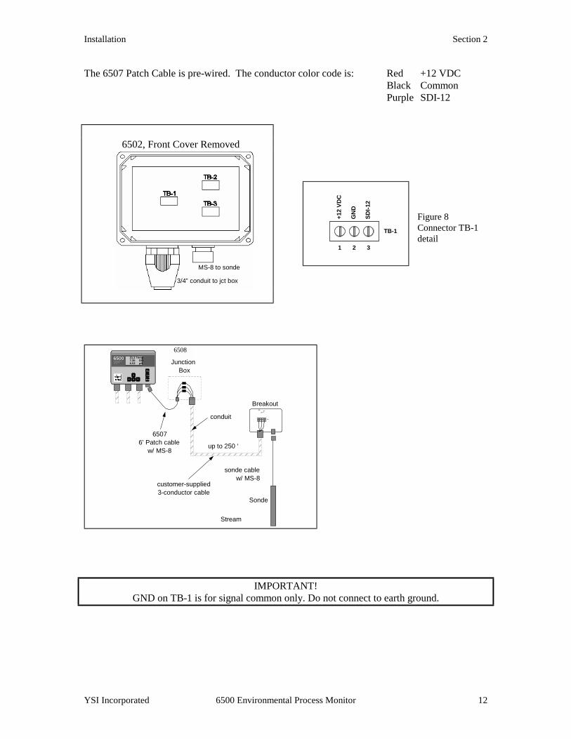
The 6507 Patch Cable is pre-wired. The conductor color code is: Red +12 VDC Black Common Purple SDI-12
Figure 8 Connector TB-1 detail
6508
Enter
Esc
Cal
65006500ENVIRONMEN TALENVIRONMEN TALMONITORINGMONITORINGSYSTE MSYSTE M
21.2 Temp7.35 DO6.53 pH Junction
Box
sonde cablew/ MS-8
Stream
Sonde
Breakout
up to 250 ‘
conduit
65076’ Patch cable
w/ MS-8
customer-supplied3-conductor cable
1 32
+12VDC
GND
SDI-12
TB-1
IMPORTANT! GND on TB-1 is for signal common only. Do not connect to earth ground.
6502, Front Cover Removed
MS-8 to sonde
3/4” conduit to jct box
1 32
+12
VDC
GN
D
SDI-1
2
TB-1

Installation Section 2
YSI Incorporated 6500 Environmental Process Monitor 13
2.5.2 AC POWER INPU2.5.2 AC POWER INPU2.5.2 AC POWER INPU2.5.2 AC POWER INPUT WIRINGT WIRINGT WIRINGT WIRING The 6500 Monitor has a switching power supply and can operate on 100 to 240 VAC power. When you remove the front panel of the 6500 Monitor, take care not to drop the cover since it is not hinged to the Monitor. Refer to figure 8 for power installation. Connect AC power to TB1-1, L1 and L2. Connect ground wire to one of the three 10-32 grounding screws using a lug (not provided). To meet compliance with UL3010, EN61010 and CSA1010, install a power switch on the AC load line external to the 6500 Monitor (Note: AC on/off power switch is not included with the 6500 Monitor package).
CAUTION! The sensitivity and stability of the monitor will be impaired if the input wiring is not grounded. Do not apply power to the Monitor until all electrical connections are verified and secure. Figure 10 6500 Terminal Connections (6500 Cover Removed)
RS485 forModbus
RS232 for Modbus andsoftware upgrades
Single 12-pin connectorfor relay outputs
AC Powerconnector
8-pin connectors (2)for 4-20 mA outputs
Relays (4)...soldered to PCB
L1 L2
GroundingScrews (10-32)
B- A-GN
Installation Section 2
YSI Incorporated 6500 Environmental Process Monitor 14
Use the following precautions from UL 508 as a guide to safety for personnel and property. $ AC connections and grounding must be in compliance with UL 508 and/or local electrical
codes. $ The metal stiffener provides support and proper electrical continuity between conduit
fittings. $ This type 4/4X enclosure requires a conduit hub or equivalent that provides watertight
connection, REF UL 508-26.10. $ Watertight fittings/hubs that comply with the requirements of UL 514B are to be used. $ Conduit hubs are to be connected to the conduit before the hub is connected to the enclosure,
REF UL 508.26.10. $ If the metal support plate is not used, plastic fittings must be used to prevent structural
damage to the Monitor. Also, the appropriate grounding lug and AWG conductor must be used with the plastic fittings. When using plastic connectors and non-metallic liquid-tight conduit note that the maximum conduit run length is 6 feet, REF NEC351-23-b3.
2.5.3 RELAY OUTPUT 2.5.3 RELAY OUTPUT 2.5.3 RELAY OUTPUT 2.5.3 RELAY OUTPUT WIRINGWIRINGWIRINGWIRING The four (4) output relay connections are made to terminals 1 through 12 of TB-2. Relays may be wired normally open (N.O.) or normally closed (N.C.). Use appropriate wire in terms of gauge and insulation to adequately handle the voltage and current being switched by the relays. See Appendix A, Specifications, for relay specifications. Do not use power at TB-1 as a source for any of the relays in the 6500 system. Remember that relays are intended to activate alarms, phone dialers and similar devices. The relays are not intended to switch heavy loads.
4444----20 MA CURRENT LOOP20 MA CURRENT LOOP20 MA CURRENT LOOP20 MA CURRENT LOOP OUTPUT WIRING OUTPUT WIRING OUTPUT WIRING OUTPUT WIRING
The eight (8) 4-20 mA current output connections are made to TB3-1 through TB3-16. Use Belden cable #8164 (4-conductor), #8168 (8-conductor) or equivalent between the 6500 Monitor and the SCADA or recorder site.
RS232 AND RS485 TERMRS232 AND RS485 TERMRS232 AND RS485 TERMRS232 AND RS485 TERMINALSINALSINALSINALS
The RS232 port is used for 6500 Monitor software updates and optional Modbus interface. The RS485 port can also be used for an optional Modbus interface. Neither of these connectors is involved in the installation of the 6500 system.
Installation Section 2
YSI Incorporated 6500 Environmental Process Monitor 15
2.5.4 GROUNDING INF2.5.4 GROUNDING INF2.5.4 GROUNDING INF2.5.4 GROUNDING INFORMATIONORMATIONORMATIONORMATION This section contains important installation information regarding grounding of the 6500 Monitor and 6-Series Sonde. The sonde is powered by the 6500 Monitor or by batteries (depending on which sonde you have chosen) and will be operated with a “floating” ground reference. This requires that the sonde not be individually grounded. Grounding the sonde individually will cause a “ground loop”; i.e. one conductor of the sonde output grounded common to both the sonde and the meter. Grounding the sonde will cause significant performance problems with the sensors and likely result in erroneous readings.
IMPORTANT! Do not ground the sonde body.
2.5.52.5.52.5.52.5.5 SAFETY SAFETY SAFETY SAFETY IIIISSUESSSUESSSUESSSUES The electrical system must be grounded to avoid possible electrical shock or damage to the equipment.
WARNING! Turn off all power and assure power “lockout” before servicing to avoid contact with electrically powered circuits. To avoid possible electrical shock, do not touch other circuit components when making adjustments to the 6500 Monitor circuit board. Disconnect external power to the unit before connecting or disconnecting wiring.
2.5.6 LIGHTNING AND2.5.6 LIGHTNING AND2.5.6 LIGHTNING AND2.5.6 LIGHTNING AND SURGE PROTECTION SURGE PROTECTION SURGE PROTECTION SURGE PROTECTION Surge protectors are strongly recommended to protect from secondary surges and lightning on outdoor installations. Surge suppression devices should be located on the AC line supplying power to the 6500 Monitor and any signal lines connecting the 6500 Monitor to alarms, a SCADA or other data collecting device. AC line voltage surge suppressors protect field equipment on any AC line to ground from damage due to electrical transients induced in the interconnecting power lines from lightning discharges and other high voltage surges. The unit should include noise filtering, common mode

Installation Section 2
YSI Incorporated 6500 Environmental Process Monitor 16
and normal mode suppression and nanosecond reaction time. Surge suppressors should be internally fused to remove the load if the unit is overloaded or the internal protection fails. Signal line suppressors protect 4-20 mA DC current loops, low voltage signals and relay outputs from damage due to electrical transients induced in the signal lines from lightning discharges or nearby electrical devices. Signal line suppressors should be installed at each end of an analog loop. Relay outputs should be protected at the receiver end. Signal line suppressors should consist of a three-element gas tube followed by metal oxide varistors and suppressor diodes. The protective elements should be matched such that high-energy surge voltages trigger the gas surge arrester, while low energy or surge voltages affect the MOV’s and suppressor diodes. Lightning protection devices should be located as close to the sonde and monitor as possible and wired in accordance with the National Electric Code in approved watertight enclosures. If the distance between the sonde and the 6500 Monitor is less than 100 feet, only one protector per line is needed, otherwise lightning protection should be installed at both ends of the wiring runs.
IMPORTANT NOTICE This or any other installation procedure can not protect against a direct lightning strike. YSI Incorporated cannot accept liability for damage due to lightning or secondary surges.
2.62.62.62.6 SEALANTS, DESICCSEALANTS, DESICCSEALANTS, DESICCSEALANTS, DESICCANTS AND SECURING THANTS AND SECURING THANTS AND SECURING THANTS AND SECURING THE MONITORE MONITORE MONITORE MONITOR Since the 6500 Monitor, Breakout Box(s) and/or Junctions Box will likely be subjected to environmental conditions that promote formation of condensation, it is very important to follow the instructions below before securing the cover to your unit(s). This will prevent damage to the electronic components within the Monitor and extend the life of the monitoring system. Enclosed with shipment of every 6500 Environmental Monitoring System is industrial encapsulant (conduit sealer), in a cartridge for your convenience. After all wiring is complete apply the sealant to the conduit openings from the inside of the 6500 Monitor, Breakout Box and/or Junction Box if applicable. This will help prevent moisture from entering the inside of the 6500 Monitor from conduit that was used for AC power cable or signal cables. Note: If any of the conduit fittings were not used in the installation, remove the fitting and replace with a 3/4” knockout plug provided with the unit. Two knockout plugs are provided. Also enclosed with the 6500 Monitor is a box of desiccant packs. After all wiring is completed and sealant applied, place two desiccant packs inside, near the bottom right of the Monitor before securing the cover. This desiccant will consume any moisture captured during the closure to provide a low humidity environment within the Monitor. To complete the installation secure the cover of the 6500 Monitor using the four mounting screws that you removed while doing the wiring operations. Note that the cover contains a captured rubber gasket that provides the weatherproofing. Make certain that the gasket is in place and not damaged. Check to make certain that the large blue ribbon cable is not trapped in
Installation Section 2
YSI Incorporated 6500 Environmental Process Monitor 17
the gasket channel before inserting the screws. When securing the screws, take care not to cross thread. The screws are stainless steel, and the receiving threads are brass. Do not over-tighten!
IMPORTANT! Anytime the 6500 cover is removed, replace the desiccant packs with new packs.
Anytime the 6500 front panel is removed, place it on top of the 6500 Monitor or secure it so that the blue ribbon cable does not bear the weight of the cover.
2.7 INSTALLATION CH2.7 INSTALLATION CH2.7 INSTALLATION CH2.7 INSTALLATION CHECK LISTECK LISTECK LISTECK LIST # Inspect packaging for damage # Verify that all components are included # Determine optimum mounting location for 6-Series Sonde based on process parameters being
measured # Determine optimum mounting location for 6500 Monitor # Determine preferred sonde location and fabricate mounting plate if necessary # Mount the sonde # Determine preferred monitor mounting location # If monitor is not located near sonde, mount junction box for the patch cable near the monitor # If monitor is not located near sonde, mount breakout box near the sonde deployment site # Make wiring connections for sonde # Make wiring connections for relays # Make wiring connections for 4-20 mA loops # Make wiring connections for AC power, including an AC power switch external to the unit # Apply industrial capsulant to conduit fittings # Insert desiccant pack(s) into 6500 Monitor # Reinstall front cover to 6500 and, if necessary, the 6502, 6504 or 6508 # Verify that all wiring connections are secure and that the sonde is properly located in the
flow stream # Recheck grounding and surge protection installations # Connect calibrated sonde to mounting fixture and place in stream # Connect sonde cable to 6500 or 6502 or 6504 # Allow sonde circuitry and sensors to warm up for several minutes before checking readings

Installation Section 2
YSI Incorporated 6500 Environmental Process Monitor 18
SECTION 3 SECTION 3 SECTION 3 SECTION 3 SYSTEM SESYSTEM SESYSTEM SESYSTEM SETUPTUPTUPTUP This section is designed to quickly familiarize you with the hardware and software components of the 6500 Monitor, the 6-Series Sonde and the overall system. You will learn about cable connections and basic communication between the 6-Series Sonde and the 6500 Monitor. Diagrams, menu flow charts and basic written instructions will guide you through basic hardware and software setup. For the first time user, we encourage the reading and understanding of the 6-Series Sonde Operations Manual, with regard to the specific sonde that you own, before proceeding with the 6500 Monitor setup. Before you begin 6500 Monitor Setup, you must setup the sondes: ! Install the dissolved oxygen membrane ! Install the sonde’s probes ! Learn how to access sonde software ! Calibrate the sonde sensors ! Learn how to take readings with the sonde These instructions are in the 6-Series Sonde Operations Manual, which was provided with your sonde, Section 2. Successful completion of the above list is essential for you to continue on to Section 3 of the 6500 Environmental Process Monitor Operations Manual. 3.13.13.13.1 SYSTEM CONFIGURASYSTEM CONFIGURASYSTEM CONFIGURASYSTEM CONFIGURATIONTIONTIONTION The most common configuration for the system which you have purchased involves direct interaction of the 6500 Monitor with the 6-Series Sonde, but there are also ways in which you may configure the 6-Series Sonde with various computers or handheld data displays. The latter configurations are primarily used when setting up and calibrating your sensors in the laboratory. If you calibrate your sensors in the laboratory while the sonde is disconnected from the 6500 Monitor, you should make certain that you have all of the components you need to make your system work. See your sonde manual for other possible configurations.
System Setup Section 3
YSI Incorporated 6500 Environmental Process Monitor 20
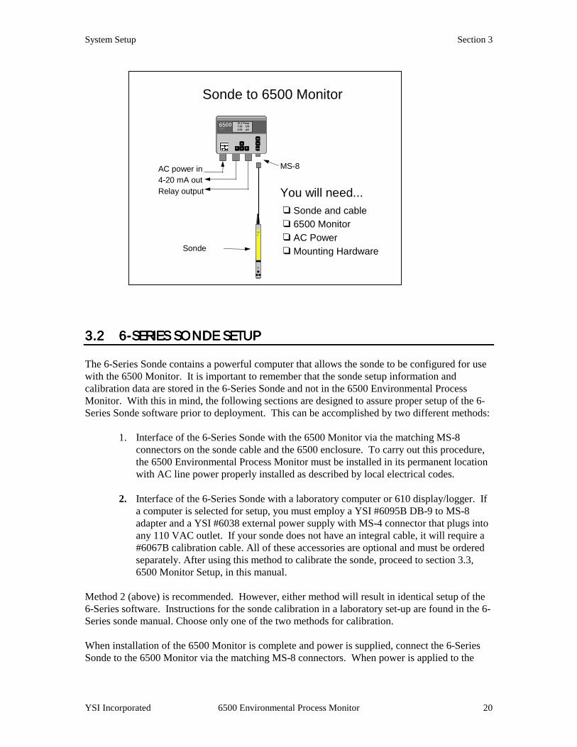
3.23.23.23.2 6666----SERIES SONDE SSERIES SONDE SSERIES SONDE SSERIES SONDE SETUP ETUP ETUP ETUP The 6-Series Sonde contains a powerful computer that allows the sonde to be configured for use with the 6500 Monitor. It is important to remember that the sonde setup information and calibration data are stored in the 6-Series Sonde and not in the 6500 Environmental Process Monitor. With this in mind, the following sections are designed to assure proper setup of the 6-Series Sonde software prior to deployment. This can be accomplished by two different methods:
1. Interface of the 6-Series Sonde with the 6500 Monitor via the matching MS-8 connectors on the sonde cable and the 6500 enclosure. To carry out this procedure, the 6500 Environmental Process Monitor must be installed in its permanent location with AC line power properly installed as described by local electrical codes.
2. Interface of the 6-Series Sonde with a laboratory computer or 610 display/logger. If
a computer is selected for setup, you must employ a YSI #6095B DB-9 to MS-8 adapter and a YSI #6038 external power supply with MS-4 connector that plugs into any 110 VAC outlet. If your sonde does not have an integral cable, it will require a #6067B calibration cable. All of these accessories are optional and must be ordered separately. After using this method to calibrate the sonde, proceed to section 3.3, 6500 Monitor Setup, in this manual.
Method 2 (above) is recommended. However, either method will result in identical setup of the 6-Series software. Instructions for the sonde calibration in a laboratory set-up are found in the 6-Series sonde manual. Choose only one of the two methods for calibration. When installation of the 6500 Monitor is complete and power is supplied, connect the 6-Series Sonde to the 6500 Monitor via the matching MS-8 connectors. When power is applied to the
MS-8
Sonde
600
Sonde to 6500 Monitor
You will need...❑ Sonde and cable❑ 6500 Monitor❑ AC Power❑ Mounting Hardware
Enter
Esc
Cal
65006500ENVIRONMENTALENVIRONMENTAL
MONITORINGMONITORING
SYSTEMSYSTEM
21.2 Temp7.35 DO6.53 pH
AC power in4-20 mA outRelay output
System Setup Section 3
YSI Incorporated 6500 Environmental Process Monitor 21
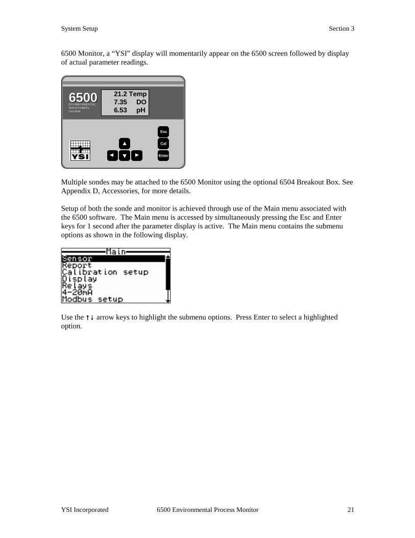
6500 Monitor, a “YSI” display will momentarily appear on the 6500 screen followed by display of actual parameter readings.
Multiple sondes may be attached to the 6500 Monitor using the optional 6504 Breakout Box. See Appendix D, Accessories, for more details. Setup of both the sonde and monitor is achieved through use of the Main menu associated with the 6500 software. The Main menu is accessed by simultaneously pressing the Esc and Enter keys for 1 second after the parameter display is active. The Main menu contains the submenu options as shown in the following display.
Use the ↑↑↑↑↓↓↓↓ arrow keys to highlight the submenu options. Press Enter to select a highlighted option.
Enter
Esc
Cal
65006500ENVIRONMENTALENVIRONMENTALMONITORINGMONITORINGSYSTEMSYSTEM
21.2 Temp 7.35 DO6.53 pH
System Setup Section 3
YSI Incorporated 6500 Environmental Process Monitor 22
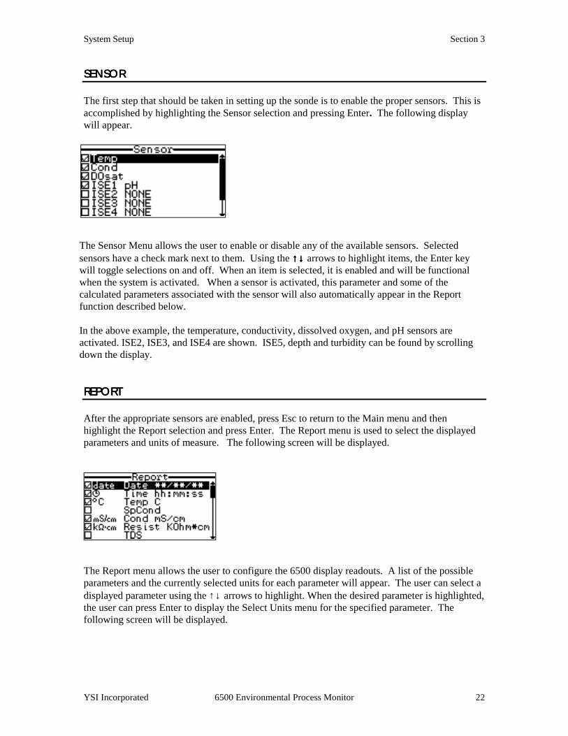
SENSORSENSORSENSORSENSOR The first step that should be taken in setting up the sonde is to enable the proper sensors. This is accomplished by highlighting the Sensor selection and pressing Enter. The following display will appear.
The Sensor Menu allows the user to enable or disable any of the available sensors. Selected sensors have a check mark next to them. Using the ↑↑↑↑↓↓↓↓ arrows to highlight items, the Enter key will toggle selections on and off. When an item is selected, it is enabled and will be functional when the system is activated. When a sensor is activated, this parameter and some of the calculated parameters associated with the sensor will also automatically appear in the Report function described below. In the above example, the temperature, conductivity, dissolved oxygen, and pH sensors are activated. ISE2, ISE3, and ISE4 are shown. ISE5, depth and turbidity can be found by scrolling down the display. REPORTREPORTREPORTREPORT After the appropriate sensors are enabled, press Esc to return to the Main menu and then highlight the Report selection and press Enter. The Report menu is used to select the displayed parameters and units of measure. The following screen will be displayed.
The Report menu allows the user to configure the 6500 display readouts. A list of the possible parameters and the currently selected units for each parameter will appear. The user can select a displayed parameter using the ↑↓ arrows to highlight. When the desired parameter is highlighted, the user can press Enter to display the Select Units menu for the specified parameter. The following screen will be displayed.
System Setup Section 3
YSI Incorporated 6500 Environmental Process Monitor 23
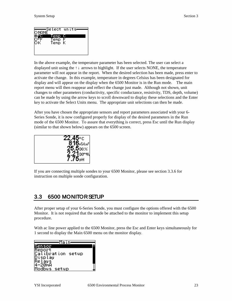
In the above example, the temperature parameter has been selected. The user can select a displayed unit using the ↑↓ arrows to highlight. If the user selects NONE, the temperature parameter will not appear in the report. When the desired selection has been made, press enter to activate the change. In this example, temperature in degrees Celsius has been designated for display and will appear on the display when the 6500 Monitor is in the Run mode. The main report menu will then reappear and reflect the change just made. Although not shown, unit changes to other parameters (conductivity, specific conductance, resistivity, TDS, depth, volume) can be made by using the arrow keys to scroll downward to display these selections and the Enter key to activate the Select Units menu. The appropriate unit selections can then be made. After you have chosen the appropriate sensors and report parameters associated with your 6-Series Sonde, it is now configured properly for display of the desired parameters in the Run mode of the 6500 Monitor. To assure that everything is correct, press Esc until the Run display (similar to that shown below) appears on the 6500 screen.
If you are connecting multiple sondes to your 6500 Monitor, please see section 3.3.6 for instruction on multiple sonde configuration. 3.33.33.33.3 6500 MONITOR SET6500 MONITOR SET6500 MONITOR SET6500 MONITOR SETUP UP UP UP After proper setup of your 6-Series Sonde, you must configure the options offered with the 6500 Monitor. It is not required that the sonde be attached to the monitor to implement this setup procedure. With ac line power applied to the 6500 Monitor, press the Esc and Enter keys simultaneously for 1 second to display the Main 6500 menu on the monitor display.

System Setup Section 3
YSI Incorporated 6500 Environmental Process Monitor 24
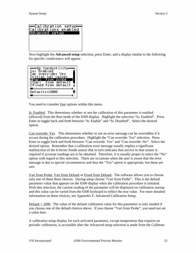
3.3.13.3.13.3.13.3.1 CALIBRATION SECALIBRATION SECALIBRATION SECALIBRATION SETUPTUPTUPTUP Highlight the Calibration setup selection and press Enter. The following screen will be displayed.
The Calibration Setup submenu presents two items: (1) Calibrations enabled is a list of all possible sensor calibrations that can either be enabled or disabled with regard to calibration from the Run mode. (2) Advanced setup is a selection that allows the user to choose whether calibration errors can be overridden and defines the default calibration value that will appear on the display during the calibration protocol. Highlight the Calibration enabled selection, press Enter, and the following screen will be displayed.
Once a calibration is selected as indicated by the check mark, that sensor may be calibrated using the Cal key during the Run mode. The user can select and deselect items using the ↑↑↑↑↓↓↓↓ arrows to highlight and press Enter to toggle selections on and off. In the example shown above, the parameters specific conductance, DO % air saturation, DO mg/L (dissolved oxygen in mg/L concentration units) can be calibrated during the Run mode of the 6500. This selection will NOT allow calibration of conductivity or salinity even if these readings appear on the display. Press Esc to return to the Calibrate setup menu.
System Setup Section 3
YSI Incorporated 6500 Environmental Process Monitor 25
Next highlight the Advanced setup selection, press Enter, and a display similar to the following for specific conductance will appear.
You need to consider four options within this menu. Is: Enabled. This determines whether or not the calibration of this parameter is enabled (allowed) from the Run mode of the 6500 display. Highlight the selection “Is: Enabled”. Press Enter to toggle back and forth between “Is: Enable” and “Is: Disabled”. Select the desired option. Can override: Yes. This determines whether or not an error message can be overridden if it occurs during the calibration procedure. Highlight the “Can override: Yes” selection. Press Enter to toggle back and forth between “Can override: Yes” and “Can override: No”. Select the desired option. Remember that a calibration error message usually implies a significant malfunction of the 6-Series Sonde sensor that in turn indicates that service to that sensor is required if accurate readings are to be obtained. Therefore, it is usually proper to select the “No” option with regard to this selection. There are occasions when the user is aware that the error message is due to special circumstances and thus the “Yes” option is appropriate, but these are rare. Vari from Probe, Vari from Default or Fixed from Default. The software allows you to choose only one of these three choices. During setup choose “Vari from Probe”. This is the default parameter value that appears on the 6500 display when the calibration procedure is initiated. With this selection, the current reading of the parameter will be displayed on calibration startup and this value can be varied from the 6500 keyboard to reflect the true value. For more detailed information on these choices, see Appendix F, Advanced Calibration Setup. Default = 1000. The value of the default calibration value for this parameter is only needed if you choose one of the default choices above. If you choose “Vari from Probe”, you need not set a value here. A calibration setup display for each activated parameter, except temperature that requires no periodic calibration, is accessible after the Advanced setup selection is made from the Calibrate
System Setup Section 3
YSI Incorporated 6500 Environmental Process Monitor 26
setup menu. To view other parameters, use the right and left arrow keys to scroll horizontally between parameters using the scroll bar at the bottom of the screen (see screen above). Use the descriptions above to set each of the 4 options for these other parameters. After configuring your sensor calibrations as described above, press Esc to return to the Main menu.
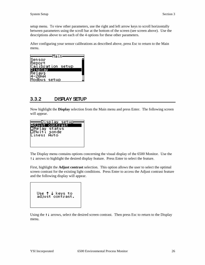
3.3.23.3.23.3.23.3.2 DISPLAY SETUPDISPLAY SETUPDISPLAY SETUPDISPLAY SETUP Now highlight the Display selection from the Main menu and press Enter. The following screen will appear.
The Display menu contains options concerning the visual display of the 6500 Monitor. Use the ↑↑↑↑↓↓↓↓ arrows to highlight the desired display feature. Press Enter to select the feature. First, highlight the Adjust contrast selection. This option allows the user to select the optimal screen contrast for the existing light conditions. Press Enter to access the Adjust contrast feature and the following display will appear.
Using the ↑↑↑↑↓↓↓↓ arrows, select the desired screen contrast. Then press Esc to return to the Display menu.

System Setup Section 3
YSI Incorporated 6500 Environmental Process Monitor 27
Tip: There is an alternate Adjust contrast feature. From the Run display screen, press and hold the Cal key while using the ↑↑↑↑↓↓↓↓ arrow keys to change contrast. This may be especially useful if bright sun or low light conditions make the display screen difficult or impossible to read. Now highlight Relay status. This feature can be enabled and disabled by toggling the Enter key. If enabled a check mark will appear in the box and the display in the Run mode will contain a bar at the bottom of the screen with symbols that indicate whether the relays are presently active as defined by the current sensor value. An example is shown in the following Run screen.
If a relay is active, the symbol will be spinning as is simulated above for relays 2 and 4. If the relay is inactive, the symbols will be stationary as shown above for relays 1 and 3. If the overall feature is disabled in the Display mode (no checkmark in the box), then no relay display will appear on the Run display screen. However, if relays are being controlled by the 6500 system, it is usually a good idea to activate this feature during setup. After making your choice, press Esc to return to the Display menu.
Now highlight the Lines selection and press Enter. The following screen will be displayed.
Four selections are possible from the Display setup menu: Auto, 2, 3 and 4 lines per screen. Highlight the desired item with the up and down arrow keys and press Enter to toggle it on. Only one choice is allowed. If you select one of the numbered options, then only that number of parameters will appear simultaneously on the screen during the Run mode. However, it is always possible to view the non-displayed parameters by scrolling up or down with the arrow keys while viewing the Run display screen. The lower the number, the larger the character size will be for the displayed
System Setup Section 3
YSI Incorporated 6500 Environmental Process Monitor 28
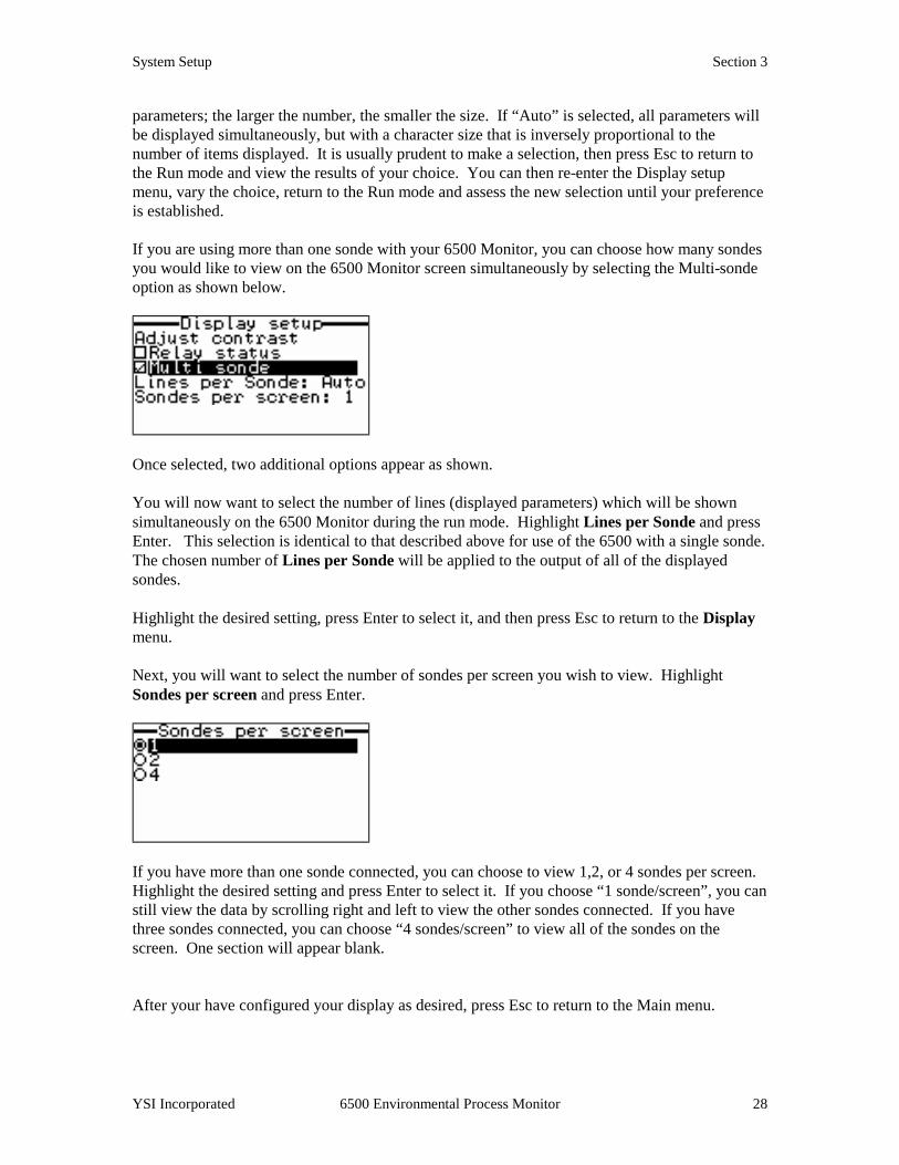
parameters; the larger the number, the smaller the size. If “Auto” is selected, all parameters will be displayed simultaneously, but with a character size that is inversely proportional to the number of items displayed. It is usually prudent to make a selection, then press Esc to return to the Run mode and view the results of your choice. You can then re-enter the Display setup menu, vary the choice, return to the Run mode and assess the new selection until your preference is established. If you are using more than one sonde with your 6500 Monitor, you can choose how many sondes you would like to view on the 6500 Monitor screen simultaneously by selecting the Multi-sonde option as shown below.
Once selected, two additional options appear as shown. You will now want to select the number of lines (displayed parameters) which will be shown simultaneously on the 6500 Monitor during the run mode. Highlight Lines per Sonde and press Enter. This selection is identical to that described above for use of the 6500 with a single sonde. The chosen number of Lines per Sonde will be applied to the output of all of the displayed sondes. Highlight the desired setting, press Enter to select it, and then press Esc to return to the Display menu. Next, you will want to select the number of sondes per screen you wish to view. Highlight Sondes per screen and press Enter.
If you have more than one sonde connected, you can choose to view 1,2, or 4 sondes per screen. Highlight the desired setting and press Enter to select it. If you choose “1 sonde/screen”, you can still view the data by scrolling right and left to view the other sondes connected. If you have three sondes connected, you can choose “4 sondes/screen” to view all of the sondes on the screen. One section will appear blank. After your have configured your display as desired, press Esc to return to the Main menu.
System Setup Section 3
YSI Incorporated 6500 Environmental Process Monitor 29
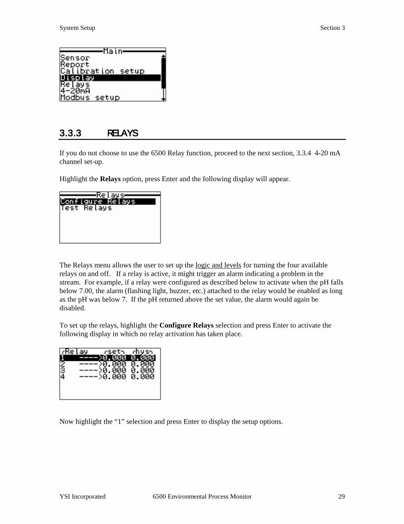
3.3.33.3.33.3.33.3.3 RELAYSRELAYSRELAYSRELAYS If you do not choose to use the 6500 Relay function, proceed to the next section, 3.3.4 4-20 mA channel set-up. Highlight the Relays option, press Enter and the following display will appear.
The Relays menu allows the user to set up the logic and levels for turning the four available relays on and off. If a relay is active, it might trigger an alarm indicating a problem in the stream. For example, if a relay were configured as described below to activate when the pH falls below 7.00, the alarm (flashing light, buzzer, etc.) attached to the relay would be enabled as long as the pH was below 7. If the pH returned above the set value, the alarm would again be disabled. To set up the relays, highlight the Configure Relays selection and press Enter to activate the following display in which no relay activation has taken place.
Now highlight the “1” selection and press Enter to display the setup options.

System Setup Section 3
YSI Incorporated 6500 Environmental Process Monitor 30
First highlight the “Para:” selection and then press Enter to choose the parameter with which the first relay will be associated from the displayed list. Highlight the desired parameter, in the example shown below temperature in degrees Celsius, and press Enter. Then press Esc to return to the above menu. Now highlight the “Is:” selection and use the Enter key to toggle between “above” and “below”. When the proper selection has been made, press Enter to confirm it (“above” in the example”). Next highlight the “Set point=“ selection and press Enter. Use the up and down arrows on the keyboard to adjust the parameter value to the point where the relay will be activated (18 C in the example) and press Enter to confirm the selection. With the above setup, the first relay will be enabled (and its associated alarm will be active) whenever the temperature is above 18 C. The “Hysteresis” (dead band) serves to eliminate relay “chatter” around the set point.
To set up the remaining three available relays, scroll horizontally with the right and left arrows in the screen shown directly above to access the Relay setup menu for the additional menus and then configure them from this display as described above. Press Esc to return to the Configure Relays menu as shown below. Conditions are now set for all four relays.
In the above example, Relay 1 will be enabled if the temperature is above 18 C, Relay 2 will be enabled if DO is less than 5.00 mg/L, Relay 3 will be enabled if specific conductance is greater than 2 mS/cm, and Relay 4 will be enabled if the pH is less than 7.00.

System Setup Section 3
YSI Incorporated 6500 Environmental Process Monitor 31
After the relays have been set as desired, press Esc to return to the Main menu.
3.3.3.3.3.43.43.43.4 4444----20 MA CHANNEL20 MA CHANNEL20 MA CHANNEL20 MA CHANNEL SETUP SETUP SETUP SETUP If you do not choose to use the 6500 4-20 mA function, proceed to the next section. To enter the 4-20 menu press Enter after highlighting “4-20 mA”, then choose “Configure 4-20mA” and press Enter again. If you will be transmitting data from the sonde via your 6500 to a SCADA system or other analog data collection device in the form of 4-20 mA signals, you will need to set the limits of this output for any or all of the eight available channels. To do so, highlight the “4-20mA” selection and press Enter. The following display will appear.
Now highlight the desired channel and press Enter to activate the display of the specific channel of interest. Channel 1 is shown below.
First, choose the parameter which will be associated with the selected 4-20 mA channel by highlighting the “Para:” selection and pressing Enter to display a list of available parameters. Using the up and down arrow keys, select the desired parameter and then press Enter to confirm the selection (temperature in degrees Celsius in the example). Next, highlight the “4mA level=“ selection and press Enter. Using the arrow keys, enter the desired value for the low limit of the range and press Enter to confirm the value (0 C in the example). Press Esc to return to the above menu. Finally, highlight the “20mA level=“ selection and enter the desired value for the high limit of the range using the arrow keys. Press Enter to confirm the value (30 C in the example).

System Setup Section 3
YSI Incorporated 6500 Environmental Process Monitor 32
Other 4-20 mA channels can be activated (and then set up) by scrolling horizontally in the above menu using the right and left arrow keys. Alternatively, you may return to the Channel menu, highlight the desired channel number (see below), and set up the limits as described above.
Channel 1 Set Channels 1-4 Set After the 4-20 mA channels have been configured to your specifications, press Esc to return to the Main menu.
3.3.5 MODBUS 3.3.5 MODBUS 3.3.5 MODBUS 3.3.5 MODBUS SETUPSETUPSETUPSETUP Please see section 5.1 for a more complete description of the Modbus system implementation. To begin setup of the Modbus, highlight the Modbus setup option on the Main menu and press Enter.
The following screen will appear.
System Setup Section 3
YSI Incorporated 6500 Environmental Process Monitor 33
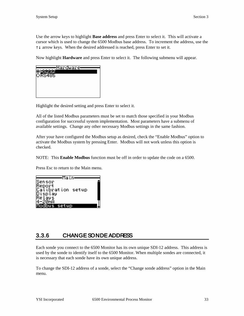
Use the arrow keys to highlight Base address and press Enter to select it. This will activate a cursor which is used to change the 6500 Modbus base address. To increment the address, use the ↑↑↑↑↓↓↓↓ arrow keys. When the desired addressed is reached, press Enter to set it. Now highlight Hardware and press Enter to select it. The following submenu will appear.
Highlight the desired setting and press Enter to select it. All of the listed Modbus parameters must be set to match those specified in your Modbus configuration for successful system implementation. Most parameters have a submenu of available settings. Change any other necessary Modbus settings in the same fashion. After your have configured the Modbus setup as desired, check the “Enable Modbus” option to activate the Modbus system by pressing Enter. Modbus will not work unless this option is checked. NOTE: This Enable Modbus function must be off in order to update the code on a 6500. Press Esc to return to the Main menu.
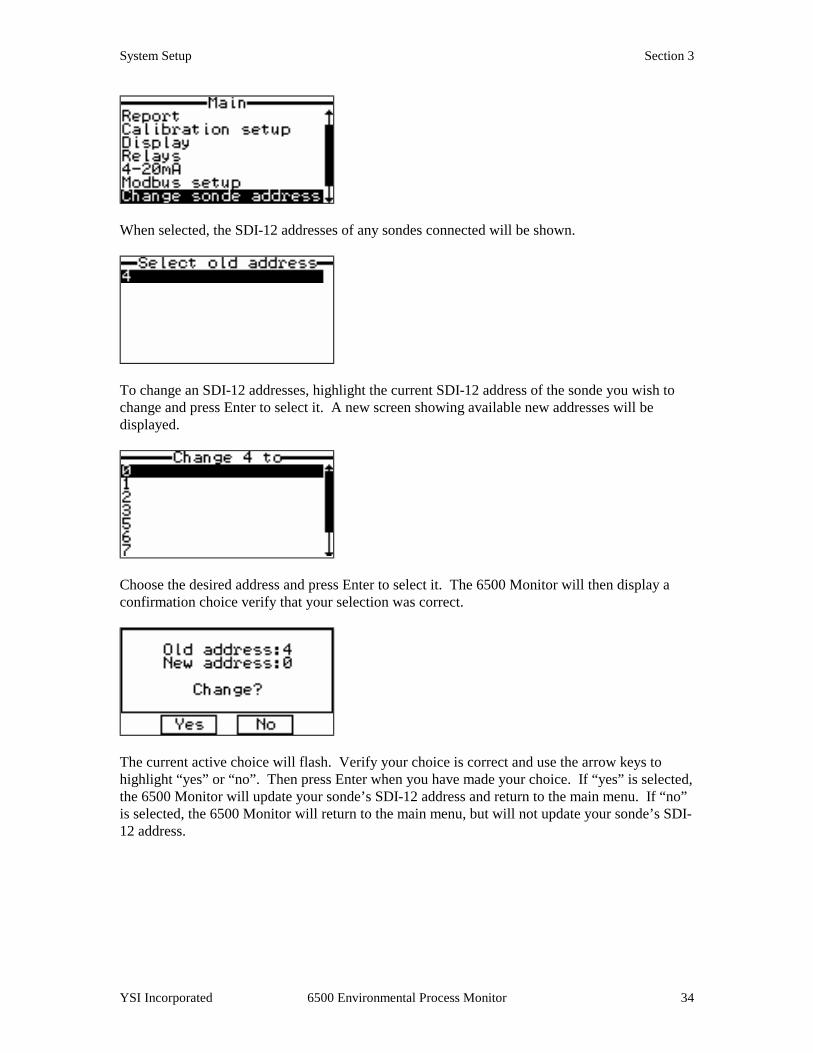
3.3.6 CHANGE3.3.6 CHANGE3.3.6 CHANGE3.3.6 CHANGE SONDE ADDRESS SONDE ADDRESS SONDE ADDRESS SONDE ADDRESS Each sonde you connect to the 6500 Monitor has its own unique SDI-12 address. This address is used by the sonde to identify itself to the 6500 Monitor. When multiple sondes are connected, it is necessary that each sonde have its own unique address. To change the SDI-12 address of a sonde, select the “Change sonde address” option in the Main menu.
System Setup Section 3
YSI Incorporated 6500 Environmental Process Monitor 34
When selected, the SDI-12 addresses of any sondes connected will be shown.
To change an SDI-12 addresses, highlight the current SDI-12 address of the sonde you wish to change and press Enter to select it. A new screen showing available new addresses will be displayed.
Choose the desired address and press Enter to select it. The 6500 Monitor will then display a confirmation choice verify that your selection was correct.
The current active choice will flash. Verify your choice is correct and use the arrow keys to highlight “yes” or “no”. Then press Enter when you have made your choice. If “yes” is selected, the 6500 Monitor will update your sonde’s SDI-12 address and return to the main menu. If “no” is selected, the 6500 Monitor will return to the main menu, but will not update your sonde’s SDI-12 address.
System Setup Section 3
YSI Incorporated 6500 Environmental Process Monitor 35
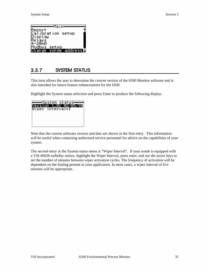
3.3.73.3.73.3.73.3.7 SYSTEM STATUSSYSTEM STATUSSYSTEM STATUSSYSTEM STATUS This item allows the user to determine the current version of the 6500 Monitor software and is also intended for future feature enhancements for the 6500. Highlight the System status selection and press Enter to produce the following display.
Note that the current software version and date are shown in the first entry. This information will be useful when contacting authorized service personnel for advice on the capabilities of your system. The second entry in the System status menu is “Wiper Interval”. If your sonde is equipped with a YSI #6026 turbidity sensor, highlight the Wiper Interval, press enter, and use the arrow keys to set the number of minutes between wiper activation cycles. The frequency of activation will be dependent on the fouling present in your application. In most cases, a wiper interval of five minutes will be appropriate.

System Setup Section 3
YSI Incorporated 6500 Environmental Process Monitor 36
SECTION 4SECTION 4SECTION 4SECTION 4 CALIBRATIOCALIBRATIOCALIBRATIOCALIBRATIONNNN In this section, you will learn how to calibrate the 6-Series Sonde sensors using the 6500 Monitor (field calibration) as the interface device. You will also learn how to view your data on a computer display.
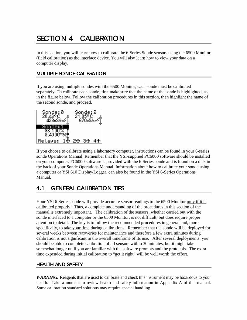
MULTIPLE SONDE CALIBMULTIPLE SONDE CALIBMULTIPLE SONDE CALIBMULTIPLE SONDE CALIBRATRATRATRATIONIONIONION
If you are using multiple sondes with the 6500 Monitor, each sonde must be calibrated separately. To calibrate each sonde, first make sure that the name of the sonde is highlighted, as in the figure below. Follow the calibration procedures in this section, then highlight the name of the second sonde, and proceed.
If you choose to calibrate using a laboratory computer, instructions can be found in your 6-series sonde Operations Manual. Remember that the YSI-supplied PC6000 software should be installed on your computer. PC6000 software is provided with the 6-Series sonde and is found on a disk in the back of your Sonde Operations Manual. Information about how to calibrate your sonde using a computer or YSI 610 Display/Logger, can also be found in the YSI 6-Series Operations Manual.
4.14.14.14.1 GENERAL CALIBRATGENERAL CALIBRATGENERAL CALIBRATGENERAL CALIBRATION TIPSION TIPSION TIPSION TIPS Your YSI 6-Series sonde will provide accurate sensor readings to the 6500 Monitor only if it is calibrated properly! Thus, a complete understanding of the procedures in this section of the manual is extremely important. The calibration of the sensors, whether carried out with the sonde interfaced to a computer or the 6500 Monitor, is not difficult, but does require proper attention to detail. The key is to follow the recommended procedures in general and, more specifically, to take your time during calibrations. Remember that the sonde will be deployed for several weeks between recoveries for maintenance and therefore a few extra minutes during calibration is not significant in the overall timeframe of its use. After several deployments, you should be able to complete calibration of all sensors within 30 minutes, but it might take somewhat longer until you are familiar with the software prompts and the protocols. The extra time expended during initial calibration to “get it right” will be well worth the effort.
HEALTH AND SAFETYHEALTH AND SAFETYHEALTH AND SAFETYHEALTH AND SAFETY
WARNING: Reagents that are used to calibrate and check this instrument may be hazardous to your health. Take a moment to review health and safety information in Appendix A of this manual. Some calibration standard solutions may require special handling.
Laboratory and Field Calibration Section 4
YSI Incorporated 6500 Environmental Process Monitor 38
CONTAINERS NEEDED TOCONTAINERS NEEDED TOCONTAINERS NEEDED TOCONTAINERS NEEDED TO CALIBRATE A SONDE CALIBRATE A SONDE CALIBRATE A SONDE CALIBRATE A SONDE
The calibration cup that comes with your sonde serves as a calibration chamber for all calibrations. You need to visually observe the turbidity calibration to insure that no air bubbles are trapped near the optics and that standards are homogeneous. If you are using the 6026 “wiping” turbidity probe, you should visually verify proper movement of the wiper mechanism. Turbidity must be calibrated with the probe guard on the sonde. Instead of the calibration cup, you may use laboratory glassware to perform calibrations. If you do not use a calibration cup that is designed for the sonde, you are cautioned to do the following: ❑ Perform all calibrations with the Probe Guard installed. This protects the probes from possible
physical damage. ❑ Use a ring stand and clamp to secure the sonde body to prevent the sonde from falling over.
Much laboratory glassware has convex bottoms. ❑ Insure that all sensors are immersed in calibration solutions. Many of the calibrations factor in
readings from other probes (e.g., temperature probe). The top vent hole of the conductivity sensor must also be immersed during calibrations.
TIPS FOR GOOD CTIPS FOR GOOD CTIPS FOR GOOD CTIPS FOR GOOD CALIBRATIONSALIBRATIONSALIBRATIONSALIBRATIONS
1. If you use the Calibration Cup for dissolved oxygen (DO) calibration,
make certain to loosen the seal to allow pressure equilibration before calibration. The DO calibration is a water-saturated air calibration.
2. The key to successful calibration is to insure that the sensors are
completely submersed when calibration values are entered. Use recommended volumes when performing calibrations.
3. For maximum accuracy, use a small amount of previously used
calibration solution to pre-rinse the sonde. You may wish to save old calibration standards for this purpose.
4. Fill a bucket with ambient temperature water to rinse the sonde between
calibration solutions. 5. Have several clean, absorbent paper towels or cotton cloths available to
dry the sonde between rinses and calibration solutions. Shake the excess rinse water off of the sonde, especially when the probe guard is installed. Dry off the outside of the sonde and probe guard. Making sure that the sonde is dry reduces carry-over contamination of calibrator solutions and increases the accuracy of the calibration.

Laboratory and Field Calibration Section 4
YSI Incorporated 6500 Environmental Process Monitor 39
6. You do not need to remove the probe guard to rinse and dry the probes between calibration solutions. The inaccuracy resulting from simply rinsing the probe compartment and drying the outside of the sonde is minimal.
7. For the 600R, 600XL and 600XLM, remove the stainless steel weight
from the bottom of the sonde by turning the weight counterclockwise. When the weight is removed, the calibration solutions have access to the sensors while displacing a minimal amount of fluid in the calibration cup. This also reduces the amount of liquid that is carried between calibrations.
8. Make certain that port plugs are installed in all ports where probes are
not installed. It is extremely important to keep these electrical connectors dry.
RECOMMENDED VOLUMES RECOMMENDED VOLUMES RECOMMENDED VOLUMES RECOMMENDED VOLUMES FOR USE WITH THE CALFOR USE WITH THE CALFOR USE WITH THE CALFOR USE WITH THE CALIBRATION CUPIBRATION CUPIBRATION CUPIBRATION CUP
Follow these instructions to use the calibration cup for calibration procedures ! Ensure that a gasket is installed in the gasket groove of the calibration cup bottom cap, and
that the bottom cap is securely tightened. Note: Do not over-tighten as this could cause damage to the threaded portions of the bottom cap and tube.
! Remove the probe guard, if it is installed. ! Remove the o-ring, if installed, from the sonde. ! Inspect the installed gasket on the sonde for obvious defects and if necessary, replace it with
the extra gasket, supplied. ! Screw cup assembly into place on the threaded end of sonde and securely tighten. Note: Do
not over tighten as this could cause damage to the threaded portions of the bottom cap and tube.
! Sonde calibration can be accomplished with the sonde upright or upside down. A separate
clamp and stand, such as a ring stand, is required to support the sonde in the inverted position.
! To calibrate, follow the procedures in the next section, Calibration Procedures. The
approximate volumes of the reagents are specified below for both the upright and upside down orientations.
When using the Transport/Calibration Cup for dissolved oxygen calibration, make certain that the vessel is vented to the atmosphere by loosening the bottom cap or cup assembly, depending on orientation, and that approximately 1/8” of water is present in the cup.
Laboratory and Field Calibration Section 4
YSI Incorporated 6500 Environmental Process Monitor 40
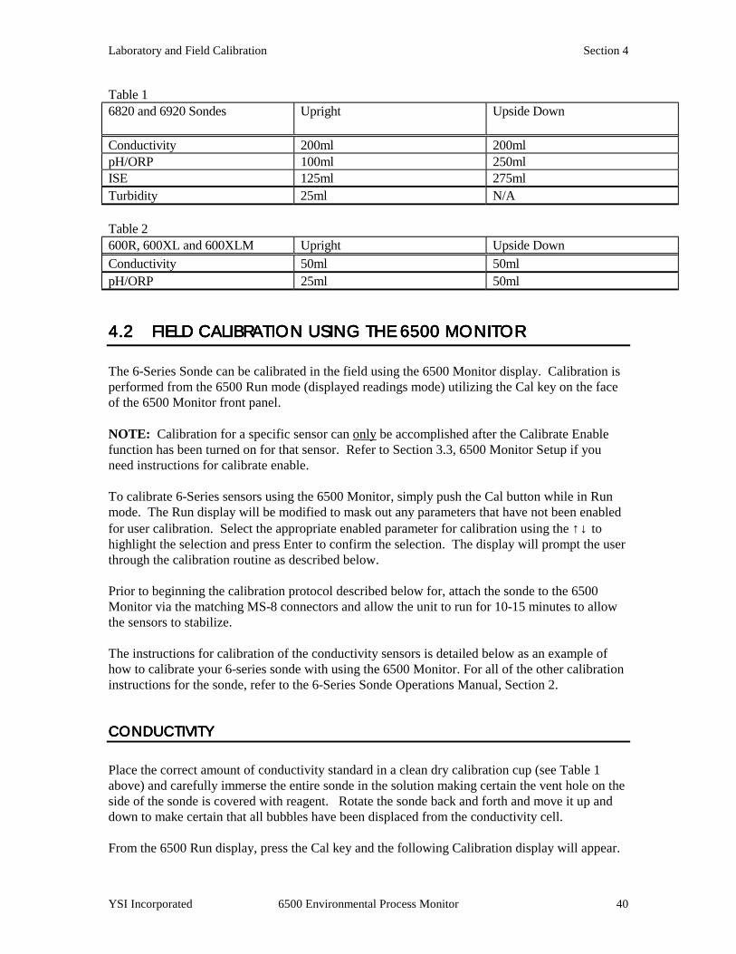
Table 1 6820 and 6920 Sondes
Upright Upside Down
Conductivity 200ml 200ml pH/ORP 100ml 250ml ISE 125ml 275ml Turbidity 25ml N/A Table 2 600R, 600XL and 600XLM Upright Upside Down Conductivity 50ml 50ml pH/ORP 25ml 50ml
4.24.24.24.2 FIELD CALIBRATIOFIELD CALIBRATIOFIELD CALIBRATIOFIELD CALIBRATION USING THE 6500 MONN USING THE 6500 MONN USING THE 6500 MONN USING THE 6500 MONITOR ITOR ITOR ITOR The 6-Series Sonde can be calibrated in the field using the 6500 Monitor display. Calibration is performed from the 6500 Run mode (displayed readings mode) utilizing the Cal key on the face of the 6500 Monitor front panel.
NOTE: Calibration for a specific sensor can only be accomplished after the Calibrate Enable function has been turned on for that sensor. Refer to Section 3.3, 6500 Monitor Setup if you need instructions for calibrate enable. To calibrate 6-Series sensors using the 6500 Monitor, simply push the Cal button while in Run mode. The Run display will be modified to mask out any parameters that have not been enabled for user calibration. Select the appropriate enabled parameter for calibration using the ↑↓ to highlight the selection and press Enter to confirm the selection. The display will prompt the user through the calibration routine as described below. Prior to beginning the calibration protocol described below for, attach the sonde to the 6500 Monitor via the matching MS-8 connectors and allow the unit to run for 10-15 minutes to allow the sensors to stabilize. The instructions for calibration of the conductivity sensors is detailed below as an example of how to calibrate your 6-series sonde with using the 6500 Monitor. For all of the other calibration instructions for the sonde, refer to the 6-Series Sonde Operations Manual, Section 2.
CONDUCTIVITYCONDUCTIVITYCONDUCTIVITYCONDUCTIVITY
Place the correct amount of conductivity standard in a clean dry calibration cup (see Table 1 above) and carefully immerse the entire sonde in the solution making certain the vent hole on the side of the sonde is covered with reagent. Rotate the sonde back and forth and move it up and down to make certain that all bubbles have been displaced from the conductivity cell. From the 6500 Run display, press the Cal key and the following Calibration display will appear.
Laboratory and Field Calibration Section 4
YSI Incorporated 6500 Environmental Process Monitor 41
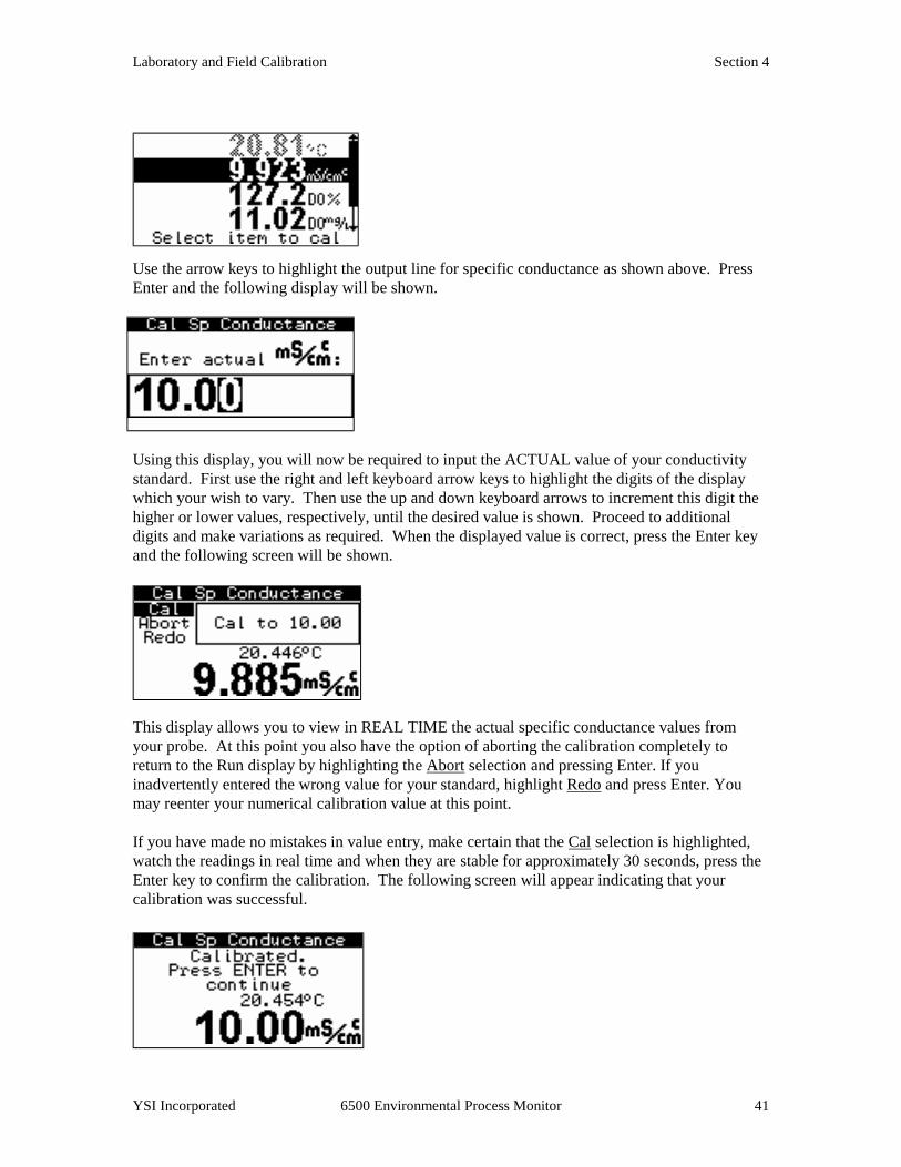
Use the arrow keys to highlight the output line for specific conductance as shown above. Press Enter and the following display will be shown.
Using this display, you will now be required to input the ACTUAL value of your conductivity standard. First use the right and left keyboard arrow keys to highlight the digits of the display which your wish to vary. Then use the up and down keyboard arrows to increment this digit the higher or lower values, respectively, until the desired value is shown. Proceed to additional digits and make variations as required. When the displayed value is correct, press the Enter key and the following screen will be shown.
This display allows you to view in REAL TIME the actual specific conductance values from your probe. At this point you also have the option of aborting the calibration completely to return to the Run display by highlighting the Abort selection and pressing Enter. If you inadvertently entered the wrong value for your standard, highlight Redo and press Enter. You may reenter your numerical calibration value at this point. If you have made no mistakes in value entry, make certain that the Cal selection is highlighted, watch the readings in real time and when they are stable for approximately 30 seconds, press the Enter key to confirm the calibration. The following screen will appear indicating that your calibration was successful.
Laboratory and Field Calibration Section 4
YSI Incorporated 6500 Environmental Process Monitor 42
Now simply press the Enter key to return to the Calibration display and proceed to calibration of the other sensors using the same basic procedures as described above for specific conductance.
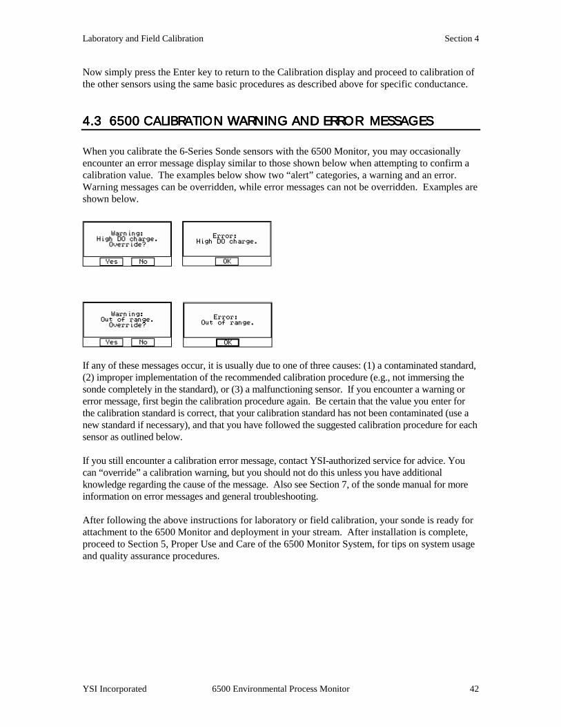
4.3 6500 CALIBRATIO4.3 6500 CALIBRATIO4.3 6500 CALIBRATIO4.3 6500 CALIBRATION WARNING AND ERROR N WARNING AND ERROR N WARNING AND ERROR N WARNING AND ERROR MESSAGES MESSAGES MESSAGES MESSAGES When you calibrate the 6-Series Sonde sensors with the 6500 Monitor, you may occasionally encounter an error message display similar to those shown below when attempting to confirm a calibration value. The examples below show two “alert” categories, a warning and an error. Warning messages can be overridden, while error messages can not be overridden. Examples are shown below.
If any of these messages occur, it is usually due to one of three causes: (1) a contaminated standard, (2) improper implementation of the recommended calibration procedure (e.g., not immersing the sonde completely in the standard), or (3) a malfunctioning sensor. If you encounter a warning or error message, first begin the calibration procedure again. Be certain that the value you enter for the calibration standard is correct, that your calibration standard has not been contaminated (use a new standard if necessary), and that you have followed the suggested calibration procedure for each sensor as outlined below. If you still encounter a calibration error message, contact YSI-authorized service for advice. You can “override” a calibration warning, but you should not do this unless you have additional knowledge regarding the cause of the message. Also see Section 7, of the sonde manual for more information on error messages and general troubleshooting. After following the above instructions for laboratory or field calibration, your sonde is ready for attachment to the 6500 Monitor and deployment in your stream. After installation is complete, proceed to Section 5, Proper Use and Care of the 6500 Monitor System, for tips on system usage and quality assurance procedures.
SECTION 5SECTION 5SECTION 5SECTION 5 PROPER USEPROPER USEPROPER USEPROPER USE AND CARE OF THE 650 AND CARE OF THE 650 AND CARE OF THE 650 AND CARE OF THE 6500 0 0 0 SYSTEMSYSTEMSYSTEMSYSTEM
You are now ready to use your system to monitor the water quality of your stream by simultaneously measuring key parameters such as temperature, dissolved oxygen, conductivity, and pH. Within this section are tips, precautions and protocol for quality assurance.
5.1 DECIDING HOW TO5.1 DECIDING HOW TO5.1 DECIDING HOW TO5.1 DECIDING HOW TO USE YOUR MONITORING USE YOUR MONITORING USE YOUR MONITORING USE YOUR MONITORING SYSTEM SYSTEM SYSTEM SYSTEM
VISUAL DISPLAY AND LVISUAL DISPLAY AND LVISUAL DISPLAY AND LVISUAL DISPLAY AND LOGGING CAPABILITYOGGING CAPABILITYOGGING CAPABILITYOGGING CAPABILITY
In the simplest configuration, the 6500 environmental process monitoring system may be used as a convenient, weatherproof visual display of parameters associated with your stream. Readings can be taken at desired time intervals and manually recorded to a notebook. These readings can be later transferred to a computer spreadsheet to help track process conditions, or use the data in compliance reporting. Two sondes, #6920 and #600XLM, have logging capability. These two sondes are able to store recorded data into their memory, which then later can be downloaded into a PC or Display/Logger. If the 6500 can not be connected to a system such as SCADA, data can still be recorded using one of these two sondes. See the 6-Series Sonde Operations Manual for more details.
ACTIVATING ALARMSACTIVATING ALARMSACTIVATING ALARMSACTIVATING ALARMS
Alternatively, if you have the required equipment, you may choose to use one of the advanced features of the 6500 system, relay activation. You can program set points for desired parameters and use up to four relays to activate visual or audible warnings regarding parameters that have fallen out of a specified range.
INTEGRATION WITHINTEGRATION WITHINTEGRATION WITHINTEGRATION WITH A SCADA A SCADA A SCADA A SCADA
If you have a SCADA system or other data collection device, the 4-20 mA loop output feature may be used to track real-time values of key parameters from the 6-Series Sonde even though the monitor/sonde deployment site is hundreds of meters away. There are eight 4-20 channels, allowing you to use more than one type of reporting unit for the four sensors available in the 6-Series Sonde. For example, you may choose to monitor dissolved oxygen in % air saturation and mg/L concentration along with temperature, conductivity, total dissolved solids, and pH.

Proper Use and Care of the 6500 Section 5
YSI Incorporated 6500 Environmental Process Monitor 44
IMPLEMENTATION OF MOIMPLEMENTATION OF MOIMPLEMENTATION OF MOIMPLEMENTATION OF MODBUS SYSTEMDBUS SYSTEMDBUS SYSTEMDBUS SYSTEM
The 6500 Modbus system can be implemented if your application requires digital data management of one or many parameters on a single data channel. This system involves a simple interface between the 6500 Monitor and a Programmable Logic Controller (PLC). Configuration of the PLC should be done only by programmers and engineers with PLC experience. The following section provides basic information for the programmer who is involved in 6500/Modbus set up. Additional advice on implementing the 6500 Modbus system can be obtained by contacting YSI Customer Service. The interaction between the PLC and the 6500 is simple. The PLC writes to and reads from the 6500 using just two of the dozens of Modbus commands. The 6500 makes use of the Modbus register system to transfer data. It will respond to two Modbus commands, “Read Holding Registers” and “Preset Multiple Registers”. All other Modbus commands are unsupported and ignored if given. The 6500 supports both RS-232 and RS-485 communications protocols. Labeling of RS-485 channels sometimes varies. When the 6500 transmits through the RS-485 port, it drives channel A high and channel B low during the active state, and in the idle state drives channel A low and channel B high. There are 4 main register areas to deal with the parameters: • Parameter type • Parameter status • IEEE floating point parameter data • Scaled integer parameter data First, the PLC writes to the parameter type registers to indicate which parameter measurements it wants. Programmers can enable and disable these sonde parameters by writing to these registers using the "Preset Multiple Register" command. Each parameter and unit is identified by a specific code available from the YSI master sensor list. The data must then be read from the 6500 by the PLC. The 6500 maintains a current set of data in the holding registers. Use the "Read Holding Registers" command to obtain the most recent set of data from sondes connected to the 6500. Each parameter from each sonde is stored in a different register (or register pair). Programmers may choose from two sets of data registers: one contains a set of IEEE floating point data, and the other contains a set of scaled integer data. The 6500 also maintains parameter status information in another set of registers. These registers contain information regarding the status of the parameters in each register. These can also be read using the “Read Holding Registers” command. Each of these areas is 15 registers long, except for the floating point data area which is 15 register pairs long. The first register (or register pair for the floating point data) in each area corresponds to the first parameter, the second corresponds to the second parameter, etc. In general if you attempt to read from a reserved or unused area, the 6500 will return a value of “0”.

Proper Use and Care of the 6500 Section 5
YSI Incorporated 6500 Environmental Process Monitor 45
The following table shows the register areas defined in the 6500: Address Read/Write Description 1-128 Unused 129-143 Read/Write Parameter type
The PLC must write to this area to tell the 6500 what parameters it wants. Up to 15 parameters can be written here. After the last parameter the PLC must write a “0”. For example to instruct the 6500 to provide depth in feet followed by temp in C the following should be written: 129: 23 (code for depth in feet) 130: 1 (code for temp in C) 131: 0 (tells the 6500 that this is the end of the list)
144-256 Unused 257-271 Read only Parameter status
The PLC can read back the values in these registers to check the status of the parameters. The value in register 257 corresponds to the parameter type in register 129 and so on. The meaning of the returned value is: 0 – The parameter is enabled in the sonde and actively functioning. 1 – The parameter type is set to 0 (code for end of list). 2 – The parameter requested is not currently available in the sonde.
272-384 Unused 385-414 Read only IEEE floating point parameter data
This is the actual parameter data in floating point form. Two registers are used for each value to make up the 32 bits required for a 4 byte IEEE floating point number. The value in register pair 385:386 corresponds to the parameter type in register 129 and so on. It is highly recommended that this be used rather than the scaled integer format. There several reasons for this: • It’s easier to use since the numbers aren’t scaled. For
example a temp C value of 22.34 would be transmitted as is, rather than as a converted value such as 7234.
• There is no implied range of values for a parameter. Using scaled values forces a limit to the range of possible values that a given parameter can take on.
• The maximum resolution of the data can be transferred. 415-640 Unused
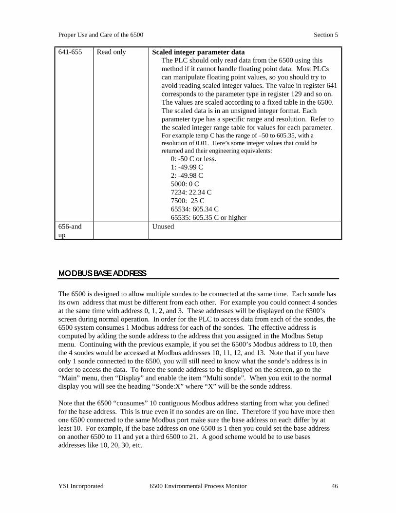
Proper Use and Care of the 6500 Section 5
YSI Incorporated 6500 Environmental Process Monitor 46
641-655 Read only Scaled integer parameter data The PLC should only read data from the 6500 using this method if it cannot handle floating point data. Most PLCs can manipulate floating point values, so you should try to avoid reading scaled integer values. The value in register 641 corresponds to the parameter type in register 129 and so on. The values are scaled according to a fixed table in the 6500. The scaled data is in an unsigned integer format. Each parameter type has a specific range and resolution. Refer to the scaled integer range table for values for each parameter. For example temp C has the range of –50 to 605.35, with a resolution of 0.01. Here’s some integer values that could be returned and their engineering equivalents:
0: -50 C or less. 1: -49.99 C 2: -49.98 C 5000: 0 C 7234: 22.34 C 7500: 25 C 65534: 605.34 C 65535: 605.35 C or higher
656-and up
Unused
MODBUS BASE ADDRESSMODBUS BASE ADDRESSMODBUS BASE ADDRESSMODBUS BASE ADDRESS
The 6500 is designed to allow multiple sondes to be connected at the same time. Each sonde has its own address that must be different from each other. For example you could connect 4 sondes at the same time with address 0, 1, 2, and 3. These addresses will be displayed on the 6500’s screen during normal operation. In order for the PLC to access data from each of the sondes, the 6500 system consumes 1 Modbus address for each of the sondes. The effective address is computed by adding the sonde address to the address that you assigned in the Modbus Setup menu. Continuing with the previous example, if you set the 6500’s Modbus address to 10, then the 4 sondes would be accessed at Modbus addresses 10, 11, 12, and 13. Note that if you have only 1 sonde connected to the 6500, you will still need to know what the sonde’s address is in order to access the data. To force the sonde address to be displayed on the screen, go to the “Main” menu, then “Display” and enable the item “Multi sonde”. When you exit to the normal display you will see the heading “Sonde:X” where “X” will be the sonde address. Note that the 6500 “consumes” 10 contiguous Modbus address starting from what you defined for the base address. This is true even if no sondes are on line. Therefore if you have more then one 6500 connected to the same Modbus port make sure the base address on each differ by at least 10. For example, if the base address on one 6500 is 1 then you could set the base address on another 6500 to 11 and yet a third 6500 to 21. A good scheme would be to use bases addresses like 10, 20, 30, etc.

Proper Use and Care of the 6500 Section 5
YSI Incorporated 6500 Environmental Process Monitor 47
MODBUS SETUP MENUMODBUS SETUP MENUMODBUS SETUP MENUMODBUS SETUP MENU
This menu is accessed from the main menu under “Modbus setup”. Menu item Item description Enable Modbus This item must be “checked” to enable Modbus.
Note: this item must be off in order to update the code on a 6500. Address The effective Modbus address is the value you set here plus the sonde
address. Hardware Select from RS232 or RS485 Format Select from ASCII or RTU Baud rate Select from 300, 600, 1200, 2400, 4800, 9600, and 19200 Data bits Select from 7 or 8. Note that in RTU mode you must select 8. Stop bits Select from 1 or 2. This only affects the data transmitted from the 6500.
Data sent to the 6500 from the PLC can be 1 or 2 stop bits. Parity Select from None, Odd or Even. Valid Messages Displays the number of correctly formatted Modbus messages the 6500
has received. This value increments to 65535 then rolls back to 0. This item has been put here to help in troubleshooting problems. If the PLC and the 6500 are setup correctly you should see this number increment every time the PLC talks to the 6500.
Param peek Brings you to a menu that shows the values set in the Parameter Type area. The values shown are not the integer value written, but rather the 6500’s translation into a real label. For example if the PLC wrote as above the values 23,1, and 0 then this menu would show the 2 items feet and temp C. This menu is provided to give you some feedback that you have correctly set the values in the Parameter Type area. All possible sonde addresses are shown, even if they are not on line. You can navigate to each by pressing the left and right arrow keys.
Please note that setup and calibration of sondes cannot be done through a Modbus interface. This sonde interaction must be performed through a direct ‘6500 to sonde’ interface.
5.2 QUALITY ASSURAN5.2 QUALITY ASSURAN5.2 QUALITY ASSURAN5.2 QUALITY ASSURANCECECECE Whatever method you choose to use with the 6500 monitor system, it is important to remember that the quality of data with regard to your stream will be heavily dependent on three factors directly related to the 6-Series Sonde: ! Proper attention to detail of and general maintenance at the physical deployment site of your
sonde. ! A well-defined quality assurance program that is carried out on a regular basis to assure that the
6-Series Sonde sensors are performing properly. ! Proper periodic calibration and maintenance of the specific sensors within the 6-Series Sonde.
Proper Use and Care of the 6500 Section 5
YSI Incorporated 6500 Environmental Process Monitor 48
The following sections are designed to help you in these important areas by providing maintenance tips for the overall sonde deployment, help in implementing a quality assurance protocol, and suggested service methods and intervals for the sonde sensors.
5.2.1 SONDE MAINTEN5.2.1 SONDE MAINTEN5.2.1 SONDE MAINTEN5.2.1 SONDE MAINTENANCE AT THE DEPLOYMEANCE AT THE DEPLOYMEANCE AT THE DEPLOYMEANCE AT THE DEPLOYMENT SITENT SITENT SITENT SITE
ALGAE AND DEBRIS AS ALGAE AND DEBRIS AS ALGAE AND DEBRIS AS ALGAE AND DEBRIS AS THE MAJOR PROBLEMTHE MAJOR PROBLEMTHE MAJOR PROBLEMTHE MAJOR PROBLEM
The problem most likely to be encountered with regard to the overall sonde deployment in municipal wastewater effluent is fouling from algae (and occasionally other debris) passed through from the clarifier of your treatment system. These algae will inevitably collect on any object immersed in the outfall stream, and, unless periodically removed, can seal off the probe compartment of the sonde. Once algal build-up occurs, it isolates the sensor environment from the bulk effluent. Thus, even though the sensors themselves may be relatively free of fouling and may be performing correctly within the isolated probe compartment, the readings may be non-representative with regard to the water that is exiting your treatment plant. To avoid, or at least minimize, this problem, it will be necessary to periodically remove the algae from the sonde. This may require the complete removal of the unit from the effluent stream and “hands on” removal of the fouling. Removal of the sonde is easier if it has been installed using an optional sonde mounting kit. See Appendix D, Accessories, for more information.
MINIMIZING THE EFFECMINIMIZING THE EFFECMINIMIZING THE EFFECMINIMIZING THE EFFECT OF ALGAE AND DEBRIT OF ALGAE AND DEBRIT OF ALGAE AND DEBRIT OF ALGAE AND DEBRISSSS
The collection of algae on your sonde and the frequency of cleaning can be minimized by the overall deployment configuration and the way in which the sonde is attached to the strut. As outlined in Section 2, Installation, it is preferable to angle the sonde with (rather than against) the current of the stream. This configuration will maximize the chances that much of the algae will be swept free of the sonde rather than collecting. Remember that no matter what precautions you take, debris will still collect on the sonde and the fouling will have to be removed by periodic cleaning. Cleaning will be easier if the method of mounting allows for easy removal and replacement of the sonde. A little extra time spent on implementing a good mounting arrangement using the optional sonde mounting kits will save a lot of time in subsequent cleaning operations. See Appendix D, Accessories for more information. The frequency with which you will have to remove fouling from your sonde varies with the water being monitored and with the physical arrangement of the sonde, but the need for cleaning can usually be ascertained by visual inspection. You can do no harm by excess cleaning, so it is best to err on the side of caution, removing and cleaning the sonde if any significant fouling is even suspected.

Proper Use and Care of the 6500 Section 5
YSI Incorporated 6500 Environmental Process Monitor 49
5.2.2 CALIBRATION C5.2.2 CALIBRATION C5.2.2 CALIBRATION C5.2.2 CALIBRATION CHECKSHECKSHECKSHECKS The sensors associated with the 6-Series Sonde are of high quality and should exhibit excellent performance in your application in excess of the warranty period. However, the dissolved oxygen, pH, and conductivity sensors will inevitably show some drift during deployment due to natural chemical changes to the reagents in the probes, physical changes of the electrodes, minor fouling of the sensor surfaces, or all of these factors. Noisy sensor readings (especially for the conductivity and dissolved oxygen sensors) signal the need for specific maintenance procedures. With these factors in mind, it will be imperative for you to establish and carry out regular checks of the quality of your sensor readings in order to assure that they are performing within their specifications, particularly if you are using the readings in compliance reporting. We recommend that you carry out the following quality assurance program WEEKLY during the initial use of your 6500 system. After several weeks of this program, you should be able to ascertain if this frequency is appropriate for your application. If only minimal drift is observed, then the frequency of implementing the protocol can be decreased. The procedure is relatively simple and should take only about 20 minutes to complete. Normally, the quality assurance measurements and recalibration can be carried out at the deployment site using the 6500 Monitor to assess the drift and to recalibrate if necessary. This method may not require the removal of the sonde from the water, greatly facilitating redeployment and shortening the downtime of the instrument. However, there are some circumstances in which the sonde should be removed to the laboratory and interfaced with a PC or 610 data logger for quality assurance procedures. For example, the pH sensor should never be exposed for more than a few minutes to subfreezing air temperatures, so under these conditions, an evaluation of the sensors in the field would likely cause damage to a key sensor and should be done in the laboratory instead.
5.2.35.2.35.2.35.2.3 RECOMMENDED Q RECOMMENDED Q RECOMMENDED Q RECOMMENDED QUALITY ASSURANCE PROUALITY ASSURANCE PROUALITY ASSURANCE PROUALITY ASSURANCE PROTOCOLTOCOLTOCOLTOCOL 1. Take the following items to the deployment site:
-bucket of clean water -the small brush supplied with the 6-Series Sonde -the calibration/storage vessel supplied with the 6-Series Sonde -pH 7 buffer and another pH buffer (usually pH 4 or pH 10) of your choice -latex gloves
2. Before going to the site, determine the current local barometric pressure reading. 3. Remove the sonde from the stream and the sonde guard from the probe compartment. 4. Manually remove any gross debris from the sensors and then rinse carefully in a bucket of
clean water, being very careful not to damage the sensors. 5. Using the small brush provided with the sonde, repeatedly scrub the two conductivity
channels. After brushing is complete, rinse the sensor with clean water by immersion in or spraying with clean water.
Proper Use and Care of the 6500 Section 5
YSI Incorporated 6500 Environmental Process Monitor 50
6. While the sonde guard is removed, inspect the dissolved oxygen membrane for obvious holes
or tears and the silver anodes for excessive darkening. Do not remove the membrane at this time.
7. Replace the sonde guard. 8. Place the sonde in enough pH 7 buffer to immerse the pH probes. Wait about 3 minutes for
the sensor to stabilize in the new medium and record the reading shown on the 6500 Monitor display. The deviation from pH 7 will reflect the sensor drift during the deployment period.
9. Activate the 2-point pH calibration protocol from the 6500 display and recalibrate the
instrument using the two buffers as described in Section 2, Sondes, of the 6-Series Sonde Operations Manual.
10. Rinse the sonde with water and place in the vented storage bottle containing about 1/8 inch
(3 mm) of water. Make sure that the dissolved oxygen sensor is not immersed in the water. 11. Wait about 5 minutes for temperature equilibration and then record the dissolved oxygen
reading in percent air saturation as shown on the 6500 display. The deviation from the current barometer reading will reflect the sensor drift during the deployment period.
12. If the dissolved oxygen readings show minimal drift (within about 5 % of the correct value)
and are stable, proceed with step #12. If excessive drift is noted or the readings are jumpy, remove the membrane and resurface the sensor as described in Section 2, Sondes, of the 6-Series Sonde Operations Manual. Then reinstall new electrolyte and a new membrane and proceed, allowing a 10-15 minute break-in period before actually implementing a new calibration.
13. Activate the DO % calibration protocol from the 6500 display and recalibrate the instrument
to the current local barometric pressure. 14. Replace the sonde in the stream and continue monitoring. NOTE: The procedure does not include quantitative data taken with regard to either the temperature or conductivity sensors. The temperature sensor only fails in very rare circumstances and, when it does, the temperature readings will seem unreasonable for the current conditions. In the unlikely event that the temperature sensor shows unusual and/or jumpy readings, the # 6560 conductivity/temperature (or the 600R sonde) will need to be checked by authorized service personnel. No user service is possible. For the conductivity sensor, drift is usually minimal except as caused by build-up of debris in the cell. Once this is cleaned out as described in Step 4 of the above protocol, the sensor almost always yields accurate readings again with no recalibration needed. However, if you wish to check your conductivity calibration, place the sonde in a known standard being sure that the top vent hole is completely covered. If significant drift has occurred, recalibrate the sensor as described in Section 2, Sondes, of the 6-Series Sonde Operations Manual.

Proper Use and Care of the 6500 Section 5
YSI Incorporated 6500 Environmental Process Monitor 51
ALTERNATIVE QUALITY ALTERNATIVE QUALITY ALTERNATIVE QUALITY ALTERNATIVE QUALITY ASSURANCE PROTOCOL (ASSURANCE PROTOCOL (ASSURANCE PROTOCOL (ASSURANCE PROTOCOL (QUICK CHECK ANQUICK CHECK ANQUICK CHECK ANQUICK CHECK AND D D D ADJUSTMENT)ADJUSTMENT)ADJUSTMENT)ADJUSTMENT)
An alternative, complementary type of quality assurance program to that described above for the 6-Series sensors can be carried out by comparing the current dissolved oxygen and pH readings shown on the 6500 display with those taken by recently-calibrated single parameter instruments. For dissolved oxygen, the probe of a handheld DO instrument similar to the YSI Model 55 can be placed in the stream near the 6-Series Sonde and the reading recorded. If a comparison of the readings from the recently-calibrated DO meter and the 6500 indicates a drift of the deployed instrument, the 6500/6-Series system can be recalibrated to reflect the DO meter reading using the 6500 interface at the site. Note, however, that this comparison should only be used in a reset of the calibration if the 6-Series Sonde has been cleaned of all algae and other debris prior to the determination. If a gross variation is observed between the two instruments (> 1 mg/L), it is usually a sign that maintenance is required on the 6-Series DO sensor. For pH, a similar field calibration adjustment can be made using a YSI Model 60 or 63 field pH meter. Alternatively, a sample of the stream can be taken to the laboratory for evaluation of the true pH. After this value is determined, you should immediately return to the deployment site and, leaving the 6-Series Sonde in the water, perform a single point pH calibration using the 6500 interface and inputting the laboratory pH as the calibration value. It is important to remember, however, that this “adjustment” of DO and pH values to those determined by recently calibrated single parameter instruments should only be used to compensate for minor drifts. It is not a substitute for the detailed quality assurance procedure outlined above which confirms proper sensor function and which should always be performed on a regular basis.
5.2.45.2.45.2.45.2.4 RECOMMENDED MORECOMMENDED MORECOMMENDED MORECOMMENDED MONTHLY MAINTENANCE OFNTHLY MAINTENANCE OFNTHLY MAINTENANCE OFNTHLY MAINTENANCE OF THE DO THE DO THE DO THE DO PROBEPROBEPROBEPROBE
The YSI polargraphic Rapid Pulse dissolved oxygen probe installed in the 6-Series Sonde is a Clark-type sensor in which the reduction of oxygen at the gold cathode is accompanied by a corresponding oxidation of a silver anode to silver chloride (AgCl). This natural deposition of AgCl will be seen initially as a slight darkening of one of the silver surfaces on the probe face with no compromise in sensor accuracy. Eventually, however, the AgCl coating will become so thick that it will affect the function of the sensor, usually resulting in erroneously low and noisy DO readings.
IMPORTANT! Periodic resurfacing of the DO sensor is required in order to obtain accurate sensor output.
Our experience in water quality monitoring suggests that DO readings will begin to deteriorate from this electrochemical action after about 30 days under the continuous operation associated with the 6500 system. With this in mind, we recommend that users of the 6500/6-Series system establish a regular monthly schedule of sensor resurfacing as described in Section 5, Proper Use and Care of the 6500 Monitor System, even if no problems are evident. The resurfacing
gold cathode
silver anodes
Face of DO Probe

Proper Use and Care of the 6500 Section 5
YSI Incorporated 6500 Environmental Process Monitor 52
procedure is easy to carry out and takes only about 20 minutes, including the recommended break-in prior to recalibration of the sensor.
5.2.55.2.55.2.55.2.5 RECOMMENDED CLEANINGRECOMMENDED CLEANINGRECOMMENDED CLEANINGRECOMMENDED CLEANING OF THE 6500 MONITOR OF THE 6500 MONITOR OF THE 6500 MONITOR OF THE 6500 MONITOR AND AND AND AND ACCESSORIESACCESSORIESACCESSORIESACCESSORIES
Clean the 6500 Monitor and accessories as needed. Dampen a cloth with warm water and wipe the outside of the unit. You may use mild detergent with water, if necessary. Do not use acid-based, alkali-based or organic solvent-based solvents (e.g., acetone, alcohol, etc.).

SECTION 6SECTION 6SECTION 6SECTION 6 TROUBLESHOTROUBLESHOTROUBLESHOTROUBLESHOOTINGOTINGOTINGOTING The following section is designed to identify and correct the most common problems that you might encounter when using your 6500/6-Series system in a stream. Included are symptoms that involve: ♦ Communication between the 6500 Monitor and the 6-Series Sonde ♦ Enabling/disabling menu choices on the 6500 display screen ♦ Calibration Error Messages ♦ Sensor accuracy and repeatability problems related to either physical deployment or sensor
malfunction ♦ Alarm functionality ♦ 4-20 mA current loop functionality For additional troubleshooting information with regard to the sonde and its sensors, consult Section 7 of the manual supplied with your 6-Series Sonde.
6.1 COMMUNICATION P6.1 COMMUNICATION P6.1 COMMUNICATION P6.1 COMMUNICATION PROBLEMSROBLEMSROBLEMSROBLEMS Symptom: The 6500 shows no display (with or without the sonde connected). Possible Cause and Suggested Action: The contrast of your display might have been altered and/or is inappropriate for the present lighting conditions. Press and hold the Cal key while using the up and down arrow keys to alter the contrast. If this does not result in the appearance of a display, AC power may not be supplied to the 6500 from the main’s line. First, make sure that the AC circuit is active. Check switch boxes and breakers. If not active, activate it. If power is being supplied but no display is present, the power lead connection to the box may be loose.
WARNING! Turn off the power to the 6500 before proceeding with the check.
We recommend that the following tests should be carried out only by a qualified electrician or electronic engineer due to the danger of electric shock.
Loosen the 4 screws that attach the front cover to the 6500 Monitor enclosure. Swing the front cover to the left, leaving the ribbon cable attached. Examine the power connection on the top right of the box and make sure that the AC input wires are securely attached to the connector and that the connector is firmly plugged into the board. After proper connections have been assured, replace the
Troubleshooting Section 6
YSI Incorporated 6500 Environmental Process Monitor 54
front cover and reapply AC power to the unit. If a display still does not appear, turn off the power and consult authorized service for advice. Symptom: No sensor display appears when the 6-Series Sonde is connected to the 6500 Monitor -- only the message “No sonde on line” is present at the bottom of the screen. Possible Cause and Suggested Action: The sonde communication software may not be configured correctly. First, turn off the AC power to the 6500 monitor and then turn it on again. If the sensor display is still not present, it is possible that your 6-Series Sonde will have to be reconfigured while attached to a computer or 610 data logger. This reconfiguration can be easily done at the site if you have a 610 data logger. If this item is not available, you will need to remove the sonde from the deployment site and connect it to a computer with PC6000 software. This will require the following interface hardware: 6095B adapter and 6038 power supply as described in Section 3, System Setup, of this manual. If you are using a 610 data logger, connect the sonde to the logger, turn on the 610 power, and highlight the “Communications” selection. Press Enter and then highlight the “Smart Terminal” selection to display the menus of the 6-Series Sonde. In the “System” selection, activate Comm Setup and make certain that the “Auto baud” selection is activated (There will be a dot next to the choice if it is active). If the selection is not active, press Enter to activate it. Then press Esc repeatedly to return to the sonde menu selections. Next, activate the “Advanced” selection and then its submenu “Setup” selection. Make certain that both “AutoSleepRS232” and “AutoSleepSDI12” are not active. If they are active (as indicated by a dot next to the selection), highlight the item and press Enter to deactivate it. Now press Esc repeatedly to return to the 610 Main menu. Detach the sonde from the 610 and reconnect it to the 6500 Monitor. If using a computer with PC6000 to check the configuration of the 6-Series Sonde, activate the Main sonde menu according to the instructions in Section 3.2, 6-Series Sonde Setup, of this manual. Enter the “System” submenu and then the “Comm setup” submenu by pressing the appropriate number selections. Make certain that “Auto baud” is enabled. If it is not, press Enter to activate it and then press Esc repeatedly to return to the sonde Main menu. Enter the “Advanced” submenu and then the “Setup” submenu. Make certain that both “AutoSleepRS232” and “AutoSleepSDI12” are not active. If they are active (as indicated by a dot next to the selection), highlight the item and press Enter to deactivate it. Now press Esc repeatedly to return to the sonde Main menu. Detach the sonde from the computer and reconnect it to the 6500 Monitor. If the sensor display is still not present on the 6500 Monitor screen after sonde reconfiguration, consult authorized service for advice. Symptom: When multiple sondes are connected, a series of alarm beeps sound and a loss of system functionality occurs. Possible Cause and Suggested Action: This problem is most likely caused by a communication problem between your sondes and the 6500 Monitor. Each sonde you connect to the 6500 Monitor has its own unique SDI-12 address. This address is used by the sonde to identify itself to the 6500 Monitor. When multiple sondes are connected, it is necessary that each sonde have its own

Troubleshooting Section 6
YSI Incorporated 6500 Environmental Process Monitor 55
unique address. A conflicting address will cause the described communication errors between the 6500 monitor and the conflicting sondes. This problem is characterized by repeated alarm sounds and loss of 6500 Monitor functionality. If this error condition occurs, disconnect all sondes from the 6500 Monitor and proceed as outlined below. It is possible to remedy this problem by changing a conflicting SDI-12 addresss. Connect a single sonde to the 6500 Monitor and change the SDI-12 address by using the “Change sonde address” option in the Main menu (please refer to section 3.3.6). It is recommended that you begin SDI-12 addressing at address 0 and increment for each additional sonde that is connected. This will ensure that no conflicting addresses exist. Once the desired address is chosen, press Enter to select it. The sonde has now been given a new SDI-12 address. Disconnect the re-addressed sonde and connect the second sonde. Repeat the address change process, ensuring that a unique address is assigned each time. Once all your sondes are re-addressed, you can reconnect them all and proceed with your setup. Also, be sure that any future sondes connected to the 6500 monitor are assigned a unique SDI-12 address before including them in a multi-sonde configuration.
6.2 6500 MENU CHOIC6.2 6500 MENU CHOIC6.2 6500 MENU CHOIC6.2 6500 MENU CHOICE PROBLEMSE PROBLEMSE PROBLEMSE PROBLEMS Symptom: After plugging in the 6-Series sonde, sensor values appear on the 6500 display, but the default selections are not those desired. Possible Cause and Suggested Action: The proper sensors and parameters have not been configured properly in the sonde software. Press the Esc and Enter keys simultaneously for 1 second to enter the 6500 Main menu. Use the “Sensor” and “Report” selections to configure your displayed parameters as described in Section 3, System Setup, of this manual. Use the “Display” selection to configure the character size of your display as described in Section 3. When the desired selections have been completed, press Esc from the Main menu to return to the Run display. Symptom: After pressing the Cal key from the Run display, the parameter you desire to calibrate is “shaded out” and cannot be highlighted with the up and down arrow keys. Possible Cause and Suggested Action: User-calibration of this parameter has not been activated. With supervisory permission, the calibration can be enabled from the Main menu. Press the Esc and Enter keys simultaneously for 1 second to enter the 6500 Main menu. Highlight the “Calibrate setup” selection and then the “Calibrations enabled” selection. Finally, highlight the parameter you desire to calibrate and use the Enter key to toggle on the ability to calibrate. If the calibration is activated, a check mark will appear in the box next to the parameter. Press Esc repeatedly to return to the Run display and proceed with the calibration. NOTE: Temperature can not be calibrated and will remain shaded on the 6500 display screen.

Troubleshooting Section 6
YSI Incorporated 6500 Environmental Process Monitor 56
6.3 CALIBRATION ERR6.3 CALIBRATION ERR6.3 CALIBRATION ERR6.3 CALIBRATION ERROR MESSAGESOR MESSAGESOR MESSAGESOR MESSAGES Symptom: When attempting to confirm a dissolved oxygen sensor calibration, an error message appears which indicates “High DO Charge”. Possible Cause and Suggested Action: This message indicates a malfunction in the DO sensor that is generally due to the roughness of the electrodes on the surface of the probe face. The charge associated with the DO sensor must be in the range 25 to 100 or the error message will appear when calibration is attempted. If this error message is encountered, remove the probe guard from the sonde and resurface the DO probe according to the instructions in Section 2, Sondes, of the 6-Series Sonde Operations Menu.. After resurfacing the probe, activate the DO charge parameter and confirm that the value is within the acceptable range. After resurfacing, allow the sensor to run for at least 5 minutes before making a final evaluation of the charge value. If the charge value is in the acceptable range after resurfacing, proceed with the calibration protocol. If resurfacing according to the instructions does not result in a lowering of the charge, contact YSI authorized service for advice. Symptom: When attempting to confirm a dissolved oxygen, pH, or conductivity sensor calibration, an error message appears which indicates “Out of Range”. Possible Cause and Suggested Action: This message indicates that the output of the sensor being calibrated does not conform to the normal range for this parameter. This problem could be due to either a malfunctioning sensor or to a calibration solution that is out of specification. If this error message is encountered, first assure that your pH buffers and conductivity standards have not been contaminated and that your DO sensor is in air (DO % Cal) or in a solution of known dissolved oxygen concentration (DO mg/L). Also be certain that you have entered the correct value for the calibration solution. If the calibration error message continues to occur, contact authorized service to determine whether the sensor in question needs to be replaced.
6.4 SENSOR ACCURACY6.4 SENSOR ACCURACY6.4 SENSOR ACCURACY6.4 SENSOR ACCURACY AND REPEATABILITY P AND REPEATABILITY P AND REPEATABILITY P AND REPEATABILITY PROBLEMSROBLEMSROBLEMSROBLEMS Symptom: After extended deployment, any or all of the activated sensor readings seem unreasonable or noisy. Possible Cause and Suggested Action: The sonde probe compartment may have been fouled with algae or other debris creating an isolated environment which is not representative of the bulk stream. Remove the sonde from the stream completely and manually clean the sonde and sensors. Replace in the stream and note if the readings return to reasonable values.
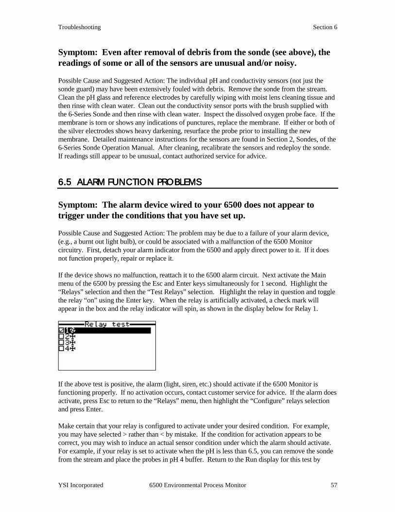
Troubleshooting Section 6
YSI Incorporated 6500 Environmental Process Monitor 57
Symptom: Even after removal of debris from the sonde (see above), the readings of some or all of the sensors are unusual and/or noisy. Possible Cause and Suggested Action: The individual pH and conductivity sensors (not just the sonde guard) may have been extensively fouled with debris. Remove the sonde from the stream. Clean the pH glass and reference electrodes by carefully wiping with moist lens cleaning tissue and then rinse with clean water. Clean out the conductivity sensor ports with the brush supplied with the 6-Series Sonde and then rinse with clean water. Inspect the dissolved oxygen probe face. If the membrane is torn or shows any indications of punctures, replace the membrane. If either or both of the silver electrodes shows heavy darkening, resurface the probe prior to installing the new membrane. Detailed maintenance instructions for the sensors are found in Section 2, Sondes, of the 6-Series Sonde Operation Manual. After cleaning, recalibrate the sensors and redeploy the sonde. If readings still appear to be unusual, contact authorized service for advice.
6.5 ALARM FUNCTION 6.5 ALARM FUNCTION 6.5 ALARM FUNCTION 6.5 ALARM FUNCTION PROBLEMSPROBLEMSPROBLEMSPROBLEMS Symptom: The alarm device wired to your 6500 does not appear to trigger under the conditions that you have set up. Possible Cause and Suggested Action: The problem may be due to a failure of your alarm device, (e.g., a burnt out light bulb), or could be associated with a malfunction of the 6500 Monitor circuitry. First, detach your alarm indicator from the 6500 and apply direct power to it. If it does not function properly, repair or replace it. If the device shows no malfunction, reattach it to the 6500 alarm circuit. Next activate the Main menu of the 6500 by pressing the Esc and Enter keys simultaneously for 1 second. Highlight the “Relays” selection and then the “Test Relays” selection. Highlight the relay in question and toggle the relay “on” using the Enter key. When the relay is artificially activated, a check mark will appear in the box and the relay indicator will spin, as shown in the display below for Relay 1.
If the above test is positive, the alarm (light, siren, etc.) should activate if the 6500 Monitor is functioning properly. If no activation occurs, contact customer service for advice. If the alarm does activate, press Esc to return to the “Relays” menu, then highlight the “Configure” relays selection and press Enter. Make certain that your relay is configured to activate under your desired condition. For example, you may have selected > rather than < by mistake. If the condition for activation appears to be correct, you may wish to induce an actual sensor condition under which the alarm should activate. For example, if your relay is set to activate when the pH is less than 6.5, you can remove the sonde from the stream and place the probes in pH 4 buffer. Return to the Run display for this test by

Troubleshooting Section 6
YSI Incorporated 6500 Environmental Process Monitor 58
pressing Esc until the actual sensor readings appears on the screen. View the readings on the display to make certain that the pH is close to the correct value (pH 4) and is indeed less than 7. If the alarm does not activate under the induced condition, contact authorized service for advice.
6.6 46.6 46.6 46.6 4----20 MA CURRENT20 MA CURRENT20 MA CURRENT20 MA CURRENT LOOP OUTPUT PROBLEM LOOP OUTPUT PROBLEM LOOP OUTPUT PROBLEM LOOP OUTPUT PROBLEMSSSS Symptom: 4-20 mA output values at the SCADA or recorder are suspicious or inconsistent with the scale you have set in the 6500 setup menu. Possible Cause and Suggested Action: The problem may be related to the 6500 circuitry, the wiring and/or the SCADA controller. Use the diagnostics menu in the 6500 Monitor to check the outputs of the 4-20 mA outputs. Start checking at the SCADA and work back to the 6500 Monitor. By starting with the SCADA input you may avoid the need to remove the front cover of the 6500 Monitor, which is often installed outside. Activate the Main menu of the 6500 by pressing the Esc and Enter keys simultaneously for 1 second. Highlight the “4-20 mA” selection and then the “Test 4-20” selection. An example display is shown below. The values shown should be the current 4-20 values for each of the active current loops. Using an ammeter verify that these readings are the same as those at the input of the SCADA controller. If they do not agree, the problem may be in the wiring or wiring connections.
Alternatively, you may highlight particular loops, one at a time, (e.g., loop 4 shown above), then enter a value of your choice. One approach is to test each loop output using 4, 12, and 20 mA signals to simulate the 0%, 50% and 100% scale of the specific parameter assigned to that loop. Then follow the procedure above to test the mA values at the input of the SCADA.
WARNING! To proceed you need to remove the cover of the 6500 Monitor, which exposes AC power
connections. A qualified electrician should perform the test below. If the wiring and input connections check okay, focus on the output connector of the 6500 Monitor. To do this use the “Test 4-20” menu to observe or assign values, then carefully remove the 6500 front cover using the 4 screws that secure it. Take care not to drop the cover and be sure to leave the blue ribbon cable connected if you want to refer back to the display. Next unplug the 4-20 mA output connector (see Figure 2.14 to locate this connector if necessary). Using an ammeter, verify that the 4-20 mA values agree with the values you read or assign. If these do not agree, the problem may be in the 6500 circuitry. Contact YSI authorized service for advice. See Section 7, Warranty and Service, for specific contact information.
SECTION 7 WARRANSECTION 7 WARRANSECTION 7 WARRANSECTION 7 WARRANTY AND SERVICE TY AND SERVICE TY AND SERVICE TY AND SERVICE INFORMATION INFORMATION INFORMATION INFORMATION The YSI 6500 Environmental Process Monitor and 6502/6503 Breakout Boxes are warranted for two years from date of purchase by the end user against defects in materials and workmanship. All cables are warranted for one year from date of purchase by the end user against defects in material and workmanship. The warranty period for chemicals and reagents is determined by the expiration date printed on their labels. Within the warranty period, YSI will repair or replace, at its sole discretion, free of charge, any product that YSI determines to be covered by this warranty. To exercise this warranty, write or call your local YSI representative, or contact YSI Customer Service in Yellow Springs, Ohio. Send the product and proof of purchase, transportation prepaid, to the Authorized Service Center selected by YSI. Repair or replacement will be made and the product returned, transportation prepaid. Repaired or replaced products are warranted for the balance of the original warranty period, or at least 90 days from date of repair or replacement. LIMITATION OF WARRANTY
This Warranty does not apply to any YSI product damage or failure caused by (i) failure to install, operate or use the product in accordance with YSI’s written instructions, (ii) abuse or misuse of the product, (iii) failure to maintain the product in accordance with YSI’s written instructions or standard industry procedure, (iv) any improper repairs to the product, (v) use by you of defective or improper components or parts in servicing or repairing the product, or (vi) modification of the product in any way not expressly authorized by YSI. THIS WARRANTY IS IN LIEU OF ALL OTHER WARRANTIES, EXPRESSED OR IMPLIED, INCLUDING ANY WARRANTY OF MERCHANTABILITY OR FITNESS FOR A PARTICULAR PURPOSE. YSI’s LIABILITY UNDER THIS WARRANTY IS LIMITED TO REPAIR OR REPLACEMENT OF THE PRODUCT, AND THIS SHALL BE YOUR SOLE AND EXCLUSIVE REMEDY FOR ANY DEFECTIVE PRODUCT COVERED BY THIS WARRANTY. IN NO EVENT SHALL YSI BE LIABLE FOR ANY SPECIAL, INDIRECT, INCIDENTAL OR CONSEQUENTIAL DAMAGES RESULTING FROM ANY DEFECTIVE PRODUCT COVERED BY THIS WARRANTY.
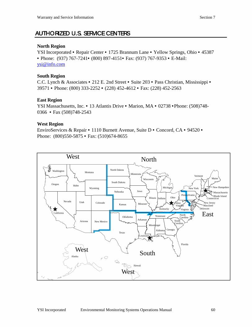
Warranty and Service Information Section 7
YSI Incorporated Environmental Monitoring Systems Operations Manual 60
AUTHORIZED U.S. SERVAUTHORIZED U.S. SERVAUTHORIZED U.S. SERVAUTHORIZED U.S. SERVICE CENTERSICE CENTERSICE CENTERSICE CENTERS North Region YSI Incorporated • Repair Center • 1725 Brannum Lane • Yellow Springs, Ohio • 45387 • Phone: (937) 767-7241• (800) 897-4151• Fax: (937) 767-9353 • E-Mail: [email protected] South Region C.C. Lynch & Associates • 212 E. 2nd Street • Suite 203 • Pass Christian, Mississippi • 39571 • Phone: (800) 333-2252 • (228) 452-4612 • Fax: (228) 452-2563 East Region YSI Massachusetts, Inc. • 13 Atlantis Drive • Marion, MA • 02738 •Phone: (508)748-0366 • Fax (508)748-2543 West Region EnviroServices & Repair • 1110 Burnett Avenue, Suite D • Concord, CA • 94520 • Phone: (800)550-5875 • Fax: (510)674-8655
Washington
Oregon
California
Nevada
Idaho
Montana
Utah
Arizona New Mexico
Colorado
Wyoming
North Dakota
South Dakota
Nebraska
Kansas
Oklahoma
Texas
Minnesota
Iowa
Missouri
Arkansas
Louisiana
Wisconsin
Illinois
Kentucky
Tennessee
Mississippi
Alabama
Florida
Georgia
SouthCarolina
Indiana Ohio
Michigan
NorthCarolina
Pennsylvania
Virginia
WestVirginia
Maine
New Hampshire
Vermont
New York
Massachusetts
Rhode IslandConnecticut
New JerseyMaryland
Alaska
Hawaii
West North
East
SouthWest
West
Delaware
Warranty and Service Information Section 7
YSI Incorporated Environmental Monitoring Systems Operations Manual 61
INTERNATIONAL SERVICINTERNATIONAL SERVICINTERNATIONAL SERVICINTERNATIONAL SERVICE CENTERSE CENTERSE CENTERSE CENTERS
YSI Incorporated •••• Repair Center •••• 1725 Brannum Lane •••• Yellow Springs, Ohio •••• 45387 •••• Phone: (937) 767-7241•••• E-Mail: [email protected] Lynchford House • Lynchford Lane • Farnborough • Hampshire • GU146LT • Phone: (44-1252) 514711 • Fax: (44-1252) 511855 • Tlx: 858210 Sakura – Building 6-5-6-13 • Shinjuku, Shinjuku-ku, Tokyo • 160 • Phone: (81-3) 5360-3561 • Fax: (81-3) 5360-3565

Warranty and Service Information Section 7
YSI Incorporated Environmental Monitoring Systems Operations Manual 62
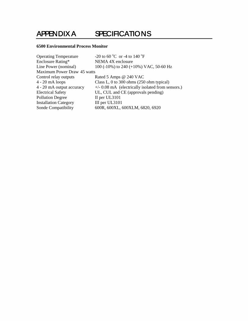
APPENDIX AAPPENDIX AAPPENDIX AAPPENDIX A SPECIFICSPECIFICSPECIFICSPECIFICATIONSATIONSATIONSATIONS 6500 Environmental Process Monitor Operating Temperature -20 to 60 oC or -4 to 140 oF Enclosure Rating* NEMA 4X enclosure Line Power (nominal) 100 (-10%) to 240 (+10%) VAC, 50-60 Hz Maximum Power Draw 45 watts Control relay outputs Rated 5 Amps @ 240 VAC 4 - 20 mA loops Class L, 0 to 300 ohms (250 ohm typical) 4 - 20 mA output accuracy +/- 0.08 mA (electrically isolated from sensors.) Electrical Safety UL, CUL and CE (approvals pending) Pollution Degree II per UL3101 Installation Category III per UL3101 Sonde Compatibility 600R, 600XL, 600XLM, 6820, 6920

Specifications Appendix A
YSI Incorporated 6500 Environmental Process Monitor 64
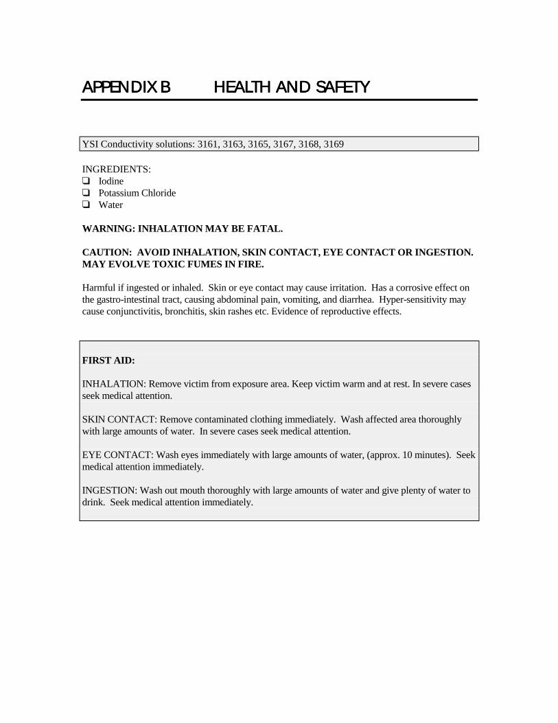
APPENDIX BAPPENDIX BAPPENDIX BAPPENDIX B HEALTH AHEALTH AHEALTH AHEALTH AND SAFETYND SAFETYND SAFETYND SAFETY
INGREDIENTS: ❑ Iodine ❑ Potassium Chloride ❑ Water WARNING: INHALATION MAY BE FATAL. CAUTION: AVOID INHALATION, SKIN CONTACT, EYE CONTACT OR INGESTION. MAY EVOLVE TOXIC FUMES IN FIRE. Harmful if ingested or inhaled. Skin or eye contact may cause irritation. Has a corrosive effect on the gastro-intestinal tract, causing abdominal pain, vomiting, and diarrhea. Hyper-sensitivity may cause conjunctivitis, bronchitis, skin rashes etc. Evidence of reproductive effects.
YSI Conductivity solutions: 3161, 3163, 3165, 3167, 3168, 3169
FIRST AID: INHALATION: Remove victim from exposure area. Keep victim warm and at rest. In severe cases seek medical attention. SKIN CONTACT: Remove contaminated clothing immediately. Wash affected area thoroughly with large amounts of water. In severe cases seek medical attention. EYE CONTACT: Wash eyes immediately with large amounts of water, (approx. 10 minutes). Seek medical attention immediately. INGESTION: Wash out mouth thoroughly with large amounts of water and give plenty of water to drink. Seek medical attention immediately.

Health and Safety Appendix B
YSI Incorporated 6500 Environmental Process Monitor 66
pH 4 INGREDIENTS: ❑ Potassium Hydrogen Phthalate ❑ Formaldehyde ❑ Water pH 7 INGREDIENTS: ❑ Sodium Phosphate, Dibasic ❑ Potassium Phosphate, Monobasic ❑ Water pH 10 INGREDIENTS: ❑ Potassium Borate, Tetra ❑ Potassium Carbonate ❑ Potassium Hydroxide ❑ Sodium (di) Ethylenediamine Tetraacetate ❑ Water CAUTION - AVOID INHALATION, SKIN CONTACT, EYE CONTACT OR INGESTION. MAY AFFECT MUCOUS MEMBRANES. Inhalation may cause severe irritation and be harmful. Skin contact may cause irritation; prolonged or repeated exposure may cause Dermatitis. Eye contact may cause irritation or conjunctivitis. Ingestion may cause nausea, vomiting and diarrhea.
YSI pH 4.00, 7.00, and 10.00 Buffer Solutions: 3821, 3822, 3823
FIRST AID: INHALATION - Remove victim from exposure area to fresh air immediately. If breathing has stopped, give artificial respiration. Keep victim warm and at rest. Seek medical attention immediately. SKIN CONTACT - Remove contaminated clothing immediately. Wash affected area with soap or mild detergent and large amounts of water (approx. 15-20 minutes). Seek medical attention immediately. EYE CONTACT - Wash eyes immediately with large amounts of water (approx. 15-20 minutes), occasionally lifting upper and lower lids. Seek medical attention immediately. INGESTION - If victim is conscious, immediately give 2 to 4 glasses of water and induce vomiting by touching finger to back of throat. Seek medical attention immediately.
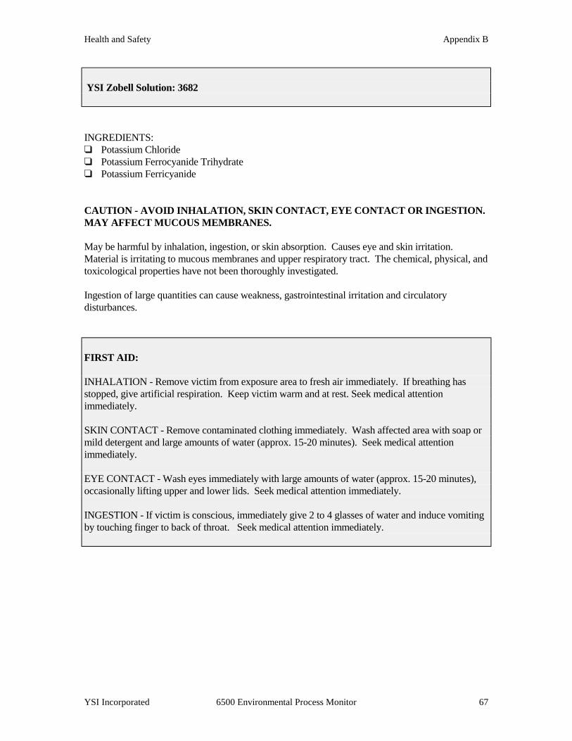
Health and Safety Appendix B
YSI Incorporated 6500 Environmental Process Monitor 67
INGREDIENTS: ❑ Potassium Chloride ❑ Potassium Ferrocyanide Trihydrate ❑ Potassium Ferricyanide CAUTION - AVOID INHALATION, SKIN CONTACT, EYE CONTACT OR INGESTION. MAY AFFECT MUCOUS MEMBRANES. May be harmful by inhalation, ingestion, or skin absorption. Causes eye and skin irritation. Material is irritating to mucous membranes and upper respiratory tract. The chemical, physical, and toxicological properties have not been thoroughly investigated. Ingestion of large quantities can cause weakness, gastrointestinal irritation and circulatory disturbances.
YSI Zobell Solution: 3682
FIRST AID: INHALATION - Remove victim from exposure area to fresh air immediately. If breathing has stopped, give artificial respiration. Keep victim warm and at rest. Seek medical attention immediately. SKIN CONTACT - Remove contaminated clothing immediately. Wash affected area with soap or mild detergent and large amounts of water (approx. 15-20 minutes). Seek medical attention immediately. EYE CONTACT - Wash eyes immediately with large amounts of water (approx. 15-20 minutes), occasionally lifting upper and lower lids. Seek medical attention immediately. INGESTION - If victim is conscious, immediately give 2 to 4 glasses of water and induce vomiting by touching finger to back of throat. Seek medical attention immediately.
Health and Safety Appendix B
YSI Incorporated 6500 Environmental Process Monitor 68
INGREDIENTS: ❑ Ammonium Chloride ❑ Lithium Acetate Dihydrate ❑ Sodium Azide (trace) ❑ Hydrochloric acid CAUTION - AVOID INHALATION, SKIN CONTACT, EYE CONTACT OR INGESTION. MAY AFFECT MUCOUS MEMBRANES. May be harmful by ingestion or skin absorption. May cause eye and skin irritation. The chemical, physical, and toxicological properties have not been thoroughly investigated. Ingestion of large quantities of lithium salts can affect the central nervous system producing symptoms ranging from dizziness to collapse. It may also cause kidney damage, nausea, and anorexia. Note that the ingestion of harmful quantitites form the solutions is considered unlikely given the low concentration of lithium and the volumes likely to be handled.
YSI Ammonium Standard Solutions: 3841, 3842, and 3843
FIRST AID: INHALATION - Remove to fresh air. If not breathing, give artificial respiration. If breathing is difficult, give oxygen. Call a physician. SKIN CONTACT - Remove contaminated clothing immediately. Wash affected area with soap or mild detergent and large amounts of water (approx. 15-20 minutes). EYE CONTACT - Wash eyes immediately with large amounts of water (approx. 15-20 minutes), occasionally lifting upper and lower lids. Seek medical attention immediately. INGESTION - Immediately rinse out mouth with large quantities of water. If reagent was swallowed, give 2 glasses of water and seek medical attention immediately.
Health and Safety Appendix B
YSI Incorporated 6500 Environmental Process Monitor 69
INGREDIENTS ❑ Potassium Nitrate ❑ Magnesium Sulfate ❑ Gentamycin Sulfate (Trace) CAUTION - AVOID INHALATION, SKIN CONTACT, EYE CONTACT OR INGESTION. May be harmful by ingestion or skin absorption. May cause eye and skin irritation. The chemical, physical, and toxicological properties have not been thoroughly investigated.
YSI Nitrate Standard Solutions: 3885, 3886, and 3887
FIRST AID: INHALATION - Remove to fresh air. If not breathing, give artificial respiration. If breathing is difficult, give oxygen. Call a physician. SKIN CONTACT - Remove contaminated clothing immediately. Wash affected area with soap or mild detergent and large amounts of water (approx. 15-20 minutes). EYE CONTACT - Wash eyes immediately with large amounts of water (approx. 15-20 minutes), occasionally lifting upper and lower lids. Seek medical attention immediately. INGESTION - Immediately rinse out mouth with large quantities of water. If irritation occurs or reagent was swallowed, seek medical attention immediately.

Health and Safety Appendix B
YSI Incorporated 6500 Environmental Process Monitor 70
INGREDIENTS ❑ Styrene divinylbenzene copolymer spheres The material is not volatile and has no known ill effects on skin, eyes, or on ingestion. Therefore, no special precautions are required when using the standards. General precautions should be adopted as required with all materials to minimize unnecessary contact. Note, however, that the chemical, physical, and toxicological properties have not been thoroughly investigated.
YSI Turbidity Standards: 3845, 3846, 3487, 6072, and 6073
FIRST AID: SKIN CONTACT - Remove contaminated clothing. Wash affected area with soap or mild detergent and water. EYE CONTACT - Wash eyes immediately with large amounts of water (approx. 15-20 minutes), occasionally lifting upper and lower lids. If irritation occurs, seek medical attention immediately. INGESTION - Rinse out mouth with large quantities of water. If irritation occurs or reagent was swallowed, seek medical attention as a precaution.

Health and Safety Appendix B
YSI Incorporated 6500 Environmental Process Monitor 71
INGREDIENTS ❑ Calcium Sulfate and Calcium Chloride CAUTION - AVOID INHALATION, SKIN CONTACT, EYE CONTACT OR INGESTION. MAY AFFECT MUCOUS MEMBRANES.
YSI Replacement Desiccant 065802
FIRST AID: SKIN CONTACT - Flush with water. EYE CONTACT - . Flush with water. If irritation continues, obtain medical attention. INGESTION - If patient is conscious, induce vomiting. Obtain medical attention.

Health and Safety Appendix B
YSI Incorporated 6500 Environmental Process Monitor 72

APPENDIX CAPPENDIX CAPPENDIX CAPPENDIX C REQUIREDREQUIREDREQUIREDREQUIRED NOTICE NOTICE NOTICE NOTICE The Federal Communications Commission defines this product as a computing device and requires the following notice. This equipment generates and uses radio frequency energy and if not installed and used properly, may cause interference to radio and television reception. It has been type tested and found to comply with the limits for a Class A or Class B computing device in accordance with the specification in Subpart J of Part 15 of FCC Rules, which are designed to provide reasonable protection against such interference in a residential installation. However, there is no guarantee that interference will not occur in a particular installation. If this equipment does cause interference to radio or television reception, which can be determined by turning the equipment off and on, the user is encouraged to try to correct the interference by one or more of the following measures: ❑ Reorient the receiving antenna ❑ Relocate the computer with respect to the receiver ❑ Move the computer away from the receiver ❑ Plug the computer into a different outlet so that the computer and receiver are on different
branch circuits. If necessary, the user should consult the dealer or an experienced radio/television technician for additional suggestions. The user may find the following booklet, prepared by the Federal Communications Commission, helpful: "How to Identify and Resolve Radio-TV Interference Problems". This booklet is available from the U.S. Government Printing Office, Washington, D.C. 20402, Stock No.0004-000-00345-4.

Required Notice Appendix C
YSI Incorporated 6500 Environmental Process Monitor 74
APPENDIX DAPPENDIX DAPPENDIX DAPPENDIX D ACCESSORACCESSORACCESSORACCESSORIES IES IES IES The following components come standard with the purchase of the YSI 6500 Environmental Monitoring System: ! 6500 Monitor ! Mounting Flange Kit ! 6506 Desiccant Kit ! 065921 Industrial Encapsulant (conduit sealer cartridge) ! 065926 Conduit Fittings (3) ! 065927 Knockout Plugs (2) ! 065902 Instruction Manual ! 065979 Field Operation Guide OPTIONAL ACCESSORIESOPTIONAL ACCESSORIESOPTIONAL ACCESSORIESOPTIONAL ACCESSORIES FOR 6500 MONITOR FOR 6500 MONITOR FOR 6500 MONITOR FOR 6500 MONITOR ♦ 6502 Breakout Box – for one sonde up to 250 feet away from the 6500 Monitor ♦ 6503 CE Breakout Box – for one sonde up to 250 feet away from the 6500 Monitor- CE approved ♦ 6504 Breakout Box – For multiple sondes up to 250 feet away from the 6500 Monitor ♦ 6505 Weather Shield – Additional protection from the elements ♦ 6507 Patch Cable, 6 feet (1.9 meters) ♦ 6508 Junction Box – Required when the distance between the Breakout Box and 6500 Monitor
is greater than 6 feet ♦ 6509 Rail Mount Kit – Mounting the 6500 Monitor, 6502, 6503, 6504 Breakout Box, and 6508
Junction Box to a railing ♦ 6510 Panel Mount Kit – Mounting the 6500 Monitor to a panel ♦ 6511 Sonde Mount Kit – Mounting the 600 series sondes ♦ 6512 Sonde Mount Kit – Mounting the 6820/6920 OPTIONAL ACCESSORIESOPTIONAL ACCESSORIESOPTIONAL ACCESSORIESOPTIONAL ACCESSORIES FOR 6 FOR 6 FOR 6 FOR 6----SERIES SONDESSERIES SONDESSERIES SONDESSERIES SONDES See the YSI 6-Series Operations Manual for list of reagents and optional accessories associated with the sonde.
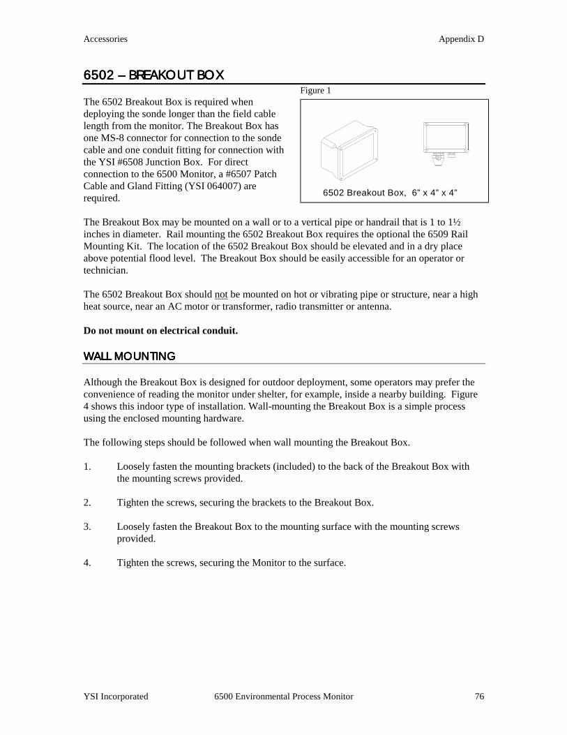
Accessories Appendix D
YSI Incorporated 6500 Environmental Process Monitor 76
6502 6502 6502 6502 –––– BREAKOUT BOX BREAKOUT BOX BREAKOUT BOX BREAKOUT BOX Figure 1
The 6502 Breakout Box is required when deploying the sonde longer than the field cable length from the monitor. The Breakout Box has one MS-8 connector for connection to the sonde cable and one conduit fitting for connection with the YSI #6508 Junction Box. For direct connection to the 6500 Monitor, a #6507 Patch Cable and Gland Fitting (YSI 064007) are required.
The Breakout Box may be mounted on a wall or to a vertical pipe or handrail that is 1 to 1½ inches in diameter. Rail mounting the 6502 Breakout Box requires the optional the 6509 Rail Mounting Kit. The location of the 6502 Breakout Box should be elevated and in a dry place above potential flood level. The Breakout Box should be easily accessible for an operator or technician.
The 6502 Breakout Box should not be mounted on hot or vibrating pipe or structure, near a high heat source, near an AC motor or transformer, radio transmitter or antenna. Do not mount on electrical conduit. WALL MOUNTING WALL MOUNTING WALL MOUNTING WALL MOUNTING Although the Breakout Box is designed for outdoor deployment, some operators may prefer the convenience of reading the monitor under shelter, for example, inside a nearby building. Figure 4 shows this indoor type of installation. Wall-mounting the Breakout Box is a simple process using the enclosed mounting hardware.
The following steps should be followed when wall mounting the Breakout Box. 1. Loosely fasten the mounting brackets (included) to the back of the Breakout Box with
the mounting screws provided. 2. Tighten the screws, securing the brackets to the Breakout Box. 3. Loosely fasten the Breakout Box to the mounting surface with the mounting screws
provided. 4. Tighten the screws, securing the Monitor to the surface.
6502 Breakout Box, 6” x 4” x 4”
Accessories Appendix D
YSI Incorporated 6500 Env
RAIL MOUNTING RAIL MOUNTING RAIL MOUNTING RAIL MOUNTING 1. Securely fasten both mounting brackets (included with the 6502) to the back of the 6502
Breakout Box, with the mounting screws provided. 2. Fasten the top and bottom of the 6502, with installed brackets, to the rail using the u-bolts,
plates, lock-washers, and nuts. 3. Ensure that all hardware is tightened. WIRING INSTRUCTIONSWIRING INSTRUCTIONSWIRING INSTRUCTIONSWIRING INSTRUCTIONS IMPORTANT! It is essential that all sensor wiring be run in a separate conduit from power wiring. The simplest configuration is where the sonde is within 250-feet (75 m) of the 6500 Monitor, the Breakout Box is within 6-ft (1.8 m) of the 6500, neither the relay outputs nor the 4-20 mA current loop outputs are used, and only AC power wiring is required. The sonde is connected to the Breakout Box by the MS-8 connectors, which are pre-wired. The Breakout Box is connected to the 6500 with the optional 6-foot (1.8 m) Patch Cable (YSI #6507). If, however, the 6500 Environmental Process Monitor is more than 6-ft (1.8 m) from the Breakout Box and any of the outputs are wired to alarms or a SCADA system, additional wiring and the 6508 Junction Box may be required. Below are wiring instructions for connection of the 6502 Breakout Box, and sondes to the 6500 Environmental Process Monitor.
Following the installation and wirifitting if used, must be sealed usinsupplied with the 6500 Environme
WARNING! A qualified electrician should perform all Wiring. Do not make connections while power is applied.
Disconnect power before proceeding.
IMPORTANT! ng of the YSI #6502 Breakout Box, the conduit g the Industrial Encapsulant and instructions ntal Monitoring System.
ironmental Process Monitor 77
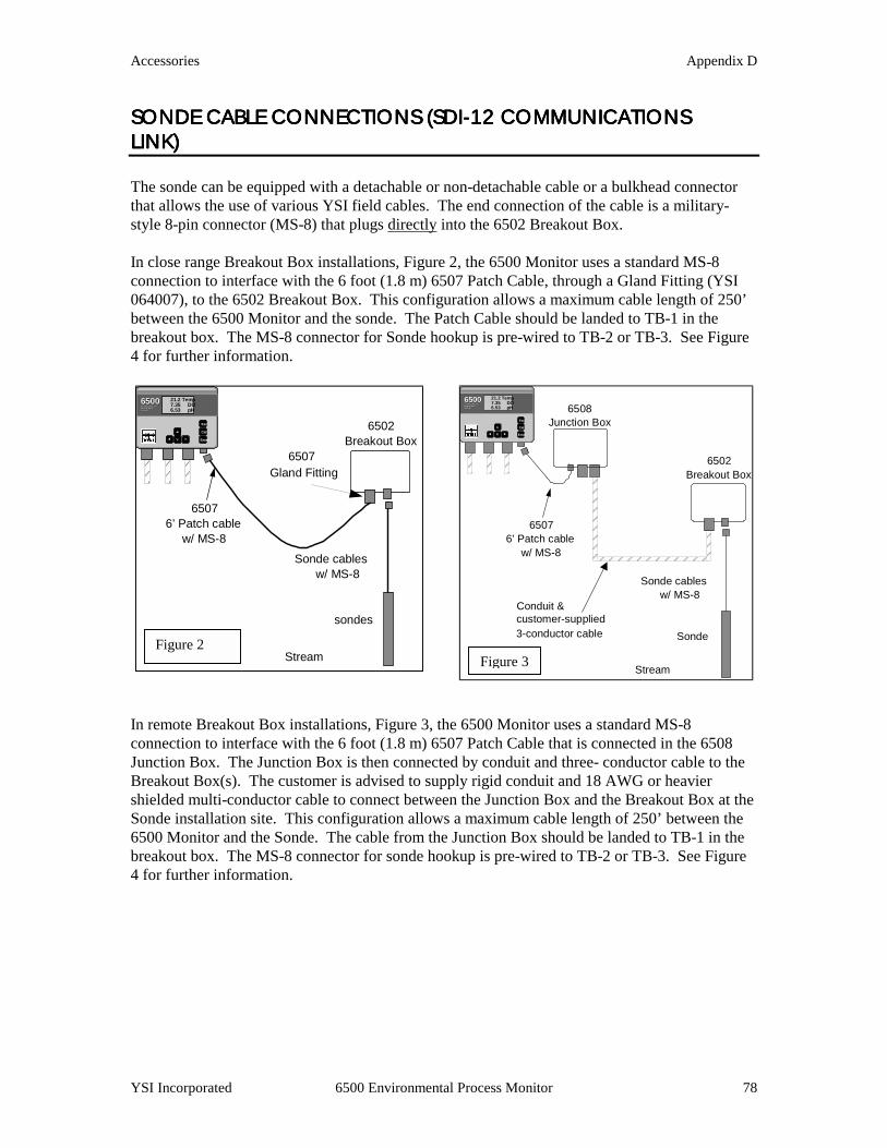
Accessories Appendix D
YSI Incorporated 6500 Environmental Pr
SONDE CABLE CONNSONDE CABLE CONNSONDE CABLE CONNSONDE CABLE CONNECTIONS (SDIECTIONS (SDIECTIONS (SDIECTIONS (SDI----12 COMM12 COMM12 COMM12 COMMUNICATIONS UNICATIONS UNICATIONS UNICATIONS LINK)LINK)LINK)LINK) The sonde can be equipped with a detachable or non-detachable cable or a bulkhead connector that allows the use of various YSI field cables. The end connection of the cable is a military-style 8-pin connector (MS-8) that plugs directly into the 6502 Breakout Box. In close range Breakout Box installations, Figure 2, the 6500 Monitor uses a standard MS-8 connection to interface with the 6 foot (1.8 m) 6507 Patch Cable, through a Gland Fitting (YSI 064007), to the 6502 Breakout Box. This configuration allows a maximum cable length of 250’ between the 6500 Monitor and the sonde. The Patch Cable should be landed to TB-1 in the breakout box. The MS-8 connector for Sonde hookup is pre-wired to TB-2 or TB-3. See Figure 4 for further information.
In remote Breakout Box installations, Figure 3, the 65connection to interface with the 6 foot (1.8 m) 6507 PJunction Box. The Junction Box is then connected bBreakout Box(s). The customer is advised to supply shielded multi-conductor cable to connect between thSonde installation site. This configuration allows a m6500 Monitor and the Sonde. The cable from the Junbreakout box. The MS-8 connector for sonde hookup4 for further information.
Enter
Esc
Cal
65006500ENVIRON MEN TALENVIRON MEN TALMO NITO RIN GMO NITO RIN GSYSTE MSYSTE M
21.2 Temp7.35 DO6.53 pH
65076’ Patch cable
w/ MS-8Sonde cables
w/ MS-8
Stream
sondes
6502Breakout Box
6507Gland Fitting
Enter
Esc
Cal
65006500ENVIRONMENTALENVIRONMENTALMONITORINGMONITORINGSYSTE MSYSTE M
21.2 Temp7.35 DO6.53 pH
Junction Box 6508
Sonde cablesw/ MS-8
Sonde
6502Breakout Box
Conduit &
65076’ Patch cable
w/ MS-8
customer-supplied3-conductor cable
Figure 2
Figure 3ocess Monitor 78
00 Monitor uses a standard MS-8 atch Cable that is connected in the 6508
y conduit and three- conductor cable to the rigid conduit and 18 AWG or heavier e Junction Box and the Breakout Box at the aximum cable length of 250’ between the ction Box should be landed to TB-1 in the is pre-wired to TB-2 or TB-3. See Figure
Stream
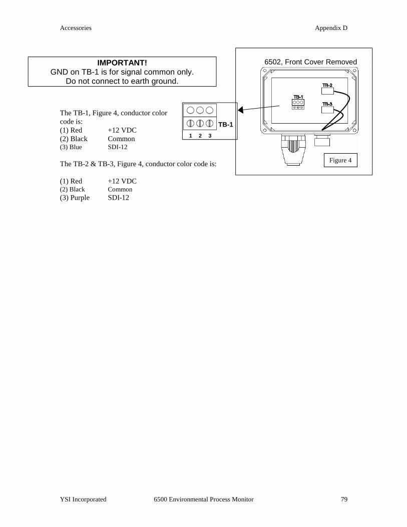
Accessories Appendix D
YSI Incorporated 6500 Environmental Process Monitor 79
The TB-1, Figure 4, conductor color code is: (1) Red +12 VDC (2) Black Common (3) Blue SDI-12 The TB-2 & TB-3, Figure 4, conductor color code is: (1) Red +12 VDC (2) Black Common (3) Purple SDI-12
6502, Front Cover Removed
(2) MS-8 to Sonde
3/4” conduit to Jct. Box
IMPORTANT! GND on TB-1 is for signal common only.
Do not connect to earth ground.
1 32
TB-1
Figure 4
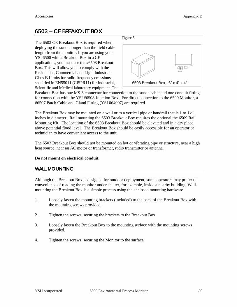
Accessories Appendix D
YSI Incorporated 6500 Environmental Process Monitor 80
6503 6503 6503 6503 –––– CE BREAKOUT B CE BREAKOUT B CE BREAKOUT B CE BREAKOUT BOXOXOXOX Figure 5 The 6503 CE Breakout Box is required when deploying the sonde longer than the field cable length from the monitor. If you are using your YSI 6500 with a Breakout Box in a CE applications, you must use the #6503 Breakout Box. This will allow you to comply with the Residential, Commercial and Light Industrial Class B Limits for radio-frequency emissions specified in EN55011 (CISPR11) for Industrial, Scientific and Medical laboratory equipment. The Breakout Box has one MS-8 connector for connection to the sonde cable and one conduit fitting for connection with the YSI #6508 Junction Box. For direct connection to the 6500 Monitor, a #6507 Patch Cable and Gland Fitting (YSI 064007) are required.
The Breakout Box may be mounted on a wall or to a vertical pipe or handrail that is 1 to 1½ inches in diameter. Rail mounting the 6503 Breakout Box requires the optional the 6509 Rail Mounting Kit. The location of the 6503 Breakout Box should be elevated and in a dry place above potential flood level. The Breakout Box should be easily accessible for an operator or technician to have convenient access to the unit.
The 6503 Breakout Box should not be mounted on hot or vibrating pipe or structure, near a high heat source, near an AC motor or transformer, radio transmitter or antenna. Do not mount on electrical conduit.
WALL MOUNTING WALL MOUNTING WALL MOUNTING WALL MOUNTING Although the Breakout Box is designed for outdoor deployment, some operators may prefer the convenience of reading the monitor under shelter, for example, inside a nearby building. Wall-mounting the Breakout Box is a simple process using the enclosed mounting hardware. 1. Loosely fasten the mounting brackets (included) to the back of the Breakout Box with
the mounting screws provided. 2. Tighten the screws, securing the brackets to the Breakout Box. 3. Loosely fasten the Breakout Box to the mounting surface with the mounting screws
provided. 4. Tighten the screws, securing the Monitor to the surface.
6503 Breakout Box, 6” x 4” x 4”

Accessories Appendix D
YSI Incorporated 6500 Environmental Process Monitor 81
RAIL MOUNTING RAIL MOUNTING RAIL MOUNTING RAIL MOUNTING 1. Securely fasten both mounting brackets
(included with the 6502) to the back of the 6502 Breakout Box as shown in Figure 6, with the mounting screws provided.
2. Fasten the top and bottom of the 6502, with
installed brackets, to the rail using the u-bolts, plates, lock-washers, and nuts as shown in Figure 7.
Ensure that all hardware is tightened.
Figure 6
Figure 7

Accessories Appendix D
YSI Incorporated 6500 Environmental Process Monitor 82
6504 6504 6504 6504 –––– BREAKOUT BOX BREAKOUT BOX BREAKOUT BOX BREAKOUT BOX The 6504 Breakout Box is required when deploying more than one sonde from the 6500 Monitor (see Figures 8 & 9). The Breakout Box has two MS-8 connectors for connection to the sonde cables and one conduit fitting for connection with the YSI #6508 Junction Box. For direct connection to the 6500 Monitor, a #6507 Patch Cable and Gland Fitting (YSI 064007) are required.
The Breakout Box may be mounted on a wall or to a vertical pipe or handrail that is 1 to 1½ inches in diameter. Rail mounting the 6504 Breakout Box requires the optional 6509 Rail Mounting Kit. The location of the 6504 Breakout Box should be elevated and in a dry place above potential flood level. The Breakout Box should be easily accessible for an operator or technician to have convenient access to the unit.
The 6504 Breakout Box should not be mounted on hot or vibrating pipe or structure, near a high heat source, near an AC motor or transformer, radio transmitter or antenna. Do not mount on electrical conduit. WALL MOUNTINGWALL MOUNTINGWALL MOUNTINGWALL MOUNTING 1. Loosely fasten the mounting brackets (included) to the back of the Breakout Box with
the mounting screws provided. 2. Tighten the screws, securing the brackets to the Breakout Box. 3. Loosely fasten the Breakout Box to the mounting surface with the mounting screws
provided. 4. Tighten the screws, securing the Monitor to the surface. RAIL MOUNTINGRAIL MOUNTINGRAIL MOUNTINGRAIL MOUNTING 1. Securely fasten both mounting brackets (included with the 6504) to the back of the 6504
Breakout Box as shown in Figure 8, with the mounting screws provided. 2. Fasten the top and bottom of the 6504, with installed brackets, to the rail using the u-
bolts, plates, lock-washers, and nuts as shown in Figure 9.
Figure 8
Figure 9

Accessories Appendix D
YSI Incorporated 6500 Env
3. Ensure that all hardware is tightened. WIRING INSTRUCTIONSWIRING INSTRUCTIONSWIRING INSTRUCTIONSWIRING INSTRUCTIONS IMPORTANT! It is essential that all sensor wiring be run in a separate conduit from power wiring. The simplest configuration is where the sondes are within 250-feet (75 m) of the 6500 Monitor, the Breakout Box is within 6-ft (1.8 m) of the 6500, neither the relay outputs nor the 4-20 mA current loop outputs are used, and only AC power wiring is required. The sondes are connected to the Breakout Box by the MS-8 connectors, which are pre-wired. The Breakout Box is connected to the 6500 with the optional 6-foot (1.8 m) Patch Cable (YSI #6507). If, however, the 6500 Environmental Process Monitor is more than 6-ft (1.8 m) from the Breakout Box and any of the outputs are wired to alarms or a SCADA system, additional wiring and the 6508 Junction Box may be required. Below are wiring instructions for connection of the 6504 Breakout Box, and sondes to the 6500 Environmental Process Monitor. SONDE CABLE CONNECTISONDE CABLE CONNECTISONDE CABLE CONNECTISONDE CABLE CONNECTIONS (SONS (SONS (SONS (S The Sonde can be equipped with a detachthat allows the use of various YSI field cstyle 8-pin connector (MS-8) that plugs d In close range Breakout Box installationsconnection to interface with the 6 foot (1064007), to the 6504 Breakout Box. Thibetween the 6500 Monitor and the Sondebreakout box. The MS-8 connectors for Figure 12 for further information.
Following the installation and wirifitting if used, must be sealed usinsupplied with the 6500 Environme
WARNING! Wiring should be performed by a qualified electrician.
Do not make connections while power is applied. Disconnect power before proceeding.
IMPORTANT! ng of the YSI #6504 Breakout Box, the conduit g the Industrial Encapsulant and instructions ntal Monitoring System.
ironmental Process Monitor 83
DDDDIIII----12 COMMUNICATIONS 12 COMMUNICATIONS 12 COMMUNICATIONS 12 COMMUNICATIONS LINK)LINK)LINK)LINK)
able or non-detachable cable or a bulkhead connector ables. The end connection of the cable is a military-irectly into the 6504 Breakout Box.
, Figure 10, the 6500 Monitor uses a standard MS-8 .8 m) 6507 Patch Cable, through a Gland Fitting (YSI s configuration allows a maximum cable length of 250’ (s). The Patch Cable should be landed to TB-1 in the Sonde hookups are pre-wired to TB-2 and TB-3. See
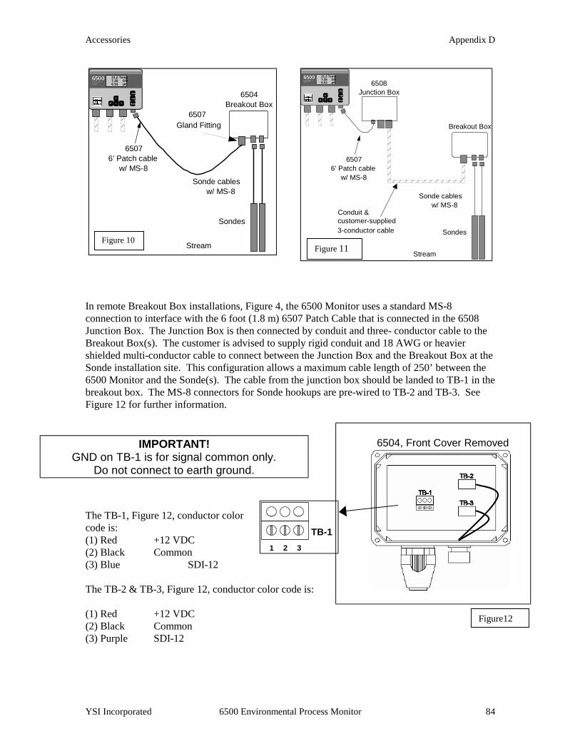
Accessories Appendix D
YSI Incorporated 6500 Environmental Process Monitor 84
In remote Breakout Box installations, Figure 4, the 6500 Monitor uses a standard MS-8 connection to interface with the 6 foot (1.8 m) 6507 Patch Cable that is connected in the 6508 Junction Box. The Junction Box is then connected by conduit and three- conductor cable to the Breakout Box(s). The customer is advised to supply rigid conduit and 18 AWG or heavier shielded multi-conductor cable to connect between the Junction Box and the Breakout Box at the Sonde installation site. This configuration allows a maximum cable length of 250’ between the 6500 Monitor and the Sonde(s). The cable from the junction box should be landed to TB-1 in the breakout box. The MS-8 connectors for Sonde hookups are pre-wired to TB-2 and TB-3. See Figure 12 for further information.
The TB-1, Figure 12, conductor color code is: (1) Red +12 VDC (2) Black Common (3) Blue SDI-12 The TB-2 & TB-3, Figure 12, conductor color code is: (1) Red +12 VDC (2) Black Common (3) Purple SDI-12
Enter
Esc
Cal
65006500ENVIRON MEN TALENVIRON MEN TALMO NITO RIN GMO NITO RIN GSYSTE MSYSTE M
21.2 Temp7.35 DO6.53 pH
65076’ Patch cable
w/ MS-8Sonde cables
w/ MS-8
Stream
Sondes
6504Breakout Box
6507Gland Fitting
Enter
Esc
Cal
65006500ENVIRONMENTALENVIRONMENTALMONITORINGMONITORINGSYSTE MSYSTE M
21.2 Temp7.35 DO6.53 pH
Junction Box 6508
Sonde cablesw/ MS-8
Stream
Sondes
Breakout Box
Conduit &
65076’ Patch cable
w/ MS-8
customer-supplied3-conductor cable
6504, Front Cover Removed
(2) MS-8 to Sonde
3/4” conduit to Jct. Box
IMPORTANT! GND on TB-1 is for signal common only.
Do not connect to earth ground.
1 32
TB-1
Figure 10 Figure 11
Figure12
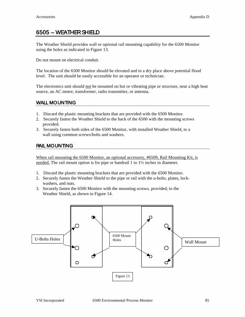
Accessories Appendix D
YSI Incorporated 6500 Environmental Process Monitor 85
6505 6505 6505 6505 –––– WEATHER WEATHER WEATHER WEATHER SHIELD SHIELD SHIELD SHIELD The Weather Shield provides wall or optional rail mounting capability for the 6500 Monitor using the holes as indicated in Figure 13. Do not mount on electrical conduit. The location of the 6500 Monitor should be elevated and in a dry place above potential flood level. The unit should be easily accessible for an operator or technician. The electronics unit should not be mounted on hot or vibrating pipe or structure, near a high heat source, an AC motor, transformer, radio transmitter, or antenna. WALL MOUNTINGWALL MOUNTINGWALL MOUNTINGWALL MOUNTING 1. Discard the plastic mounting brackets that are provided with the 6500 Monitor. 2. Securely fasten the Weather Shield to the back of the 6500 with the mounting screws provided. 3. Securely fasten both sides of the 6500 Monitor, with installed Weather Shield, to a wall using common screws/bolts and washers. RAIL MOUNTINGRAIL MOUNTINGRAIL MOUNTINGRAIL MOUNTING When rail mounting the 6500 Monitor, an optional accessory, #6509, Rail Mounting Kit, is needed. The rail mount option is for pipe or handrail 1 to 1½ inches in diameter. 1. Discard the plastic mounting brackets that are provided with the 6500 Monitor. 2. Securely fasten the Weather Shield to the pipe or rail with the u-bolts, plates, lock- washers, and nuts. 3. Securely fasten the 6500 Monitor with the mounting screws, provided, to the Weather Shield, as shown in Figure 14.
Figure 13
Wall Mount U-Bolts Holes 6500 Mount Holes

Accessories Appendix D
YSI Incorporated 6500 Environmental Process Monitor 86
Figure 14

Accessories Appendix D
YSI Incorporated 6500 Environmental Process Monitor 87
6508 6508 6508 6508 –––– JUNCTION BOX JUNCTION BOX JUNCTION BOX JUNCTION BOX The 6508 Junction Box is required when the distance between the 6500 Monitor and the Breakout Box(s) is more than 6-feet (1.8 m). The Breakout Box has two conduit fittings, one for the conduit connection with the Breakout Box and one for the Gland Fitting for the 6507 Patch Cable. The 6508 may be mounted on a wall or mounted to vertical pipe or handrail (1 to 1½ inches in diameter). Rail mounting the 6508 Junction Box requires using the enclosed mounting hardware and the optional 6509 Rail Mounting Kit. The location of the 6508 Junction Box should be elevated and in a dry place above potential flood level. The unit should be easily accessible for an operator or technician. The 6508 Junction Box should not be mounted on hot or vibrating pipe or structure, near a high heat source, near an AC motor or transformer, radio transmitter or antenna. Do not mount on electrical conduit. WALL MOUNTINWALL MOUNTINWALL MOUNTINWALL MOUNTINGGGG 1. Loosely fasten the mounting brackets (included) to
the back of the Breakout Box with the mounting screws provided.
2. Tighten the screws, securing the brackets to the Breakout Box. 3. Loosely fasten the Breakout Box to the mounting surface with the mounting screws
provided. 4. Tighten the screws, securing the Monitor to the surface. RAIL MOUNTINGRAIL MOUNTINGRAIL MOUNTINGRAIL MOUNTING 1. Securely fasten both mounting brackets (included with the 6508) to the back of the 6508
Junction Box with the mounting screws (included) as shown in Figure 15. 2. Fasten the top and bottom of the 6508, with installed brackets, to the rail with the u-bolts,
plates, lock-washers, and nuts as shown in Figure 16. 3. Ensure that all hardware is tightened.
Figure 15
Figure 16
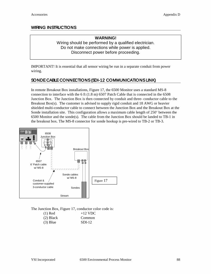
Accessories Appendix D
YSI Incorporated 6500 Environmental Process Monitor 88
WIRING INSTRUCTIONSWIRING INSTRUCTIONSWIRING INSTRUCTIONSWIRING INSTRUCTIONS
WARNING! Wiring should be performed by a qualified electrician.
Do not make connections while power is applied. Disconnect power before proceeding.
IMPORTANT! It is essential that all sensor wiring be run in a separate conduit from power wiring. SONDE CABLE CONNECTISONDE CABLE CONNECTISONDE CABLE CONNECTISONDE CABLE CONNECTIONS (SDIONS (SDIONS (SDIONS (SDI----12121212 COMMUNICATIONS LINK COMMUNICATIONS LINK COMMUNICATIONS LINK COMMUNICATIONS LINK)))) In remote Breakout Box installations, Figure 17, the 6500 Monitor uses a standard MS-8 connection to interface with the 6 ft (1.8 m) 6507 Patch Cable that is connected in the 6508 Junction Box. The Junction Box is then connected by conduit and three- conductor cable to the Breakout Box(s). The customer is advised to supply rigid conduit and 18 AWG or heavier shielded multi-conductor cable to connect between the Junction Box and the Breakout Box at the Sonde installation site. This configuration allows a maximum cable length of 250’ between the 6500 Monitor and the sonde(s). The cable from the Junction Box should be landed to TB-1 in the breakout box. The MS-8 connector for sonde hookup is pre-wired to TB-2 or TB-3.
The Junction Box, Figure 17, conductor color code is:
(1) Red +12 VDC (2) Black Common (3) Blue SDI-12
Enter
Esc
Cal
65006500ENVIRONMENTALENVIRONMENTALMONITORINGMONITORINGSYSTE MSYSTE M
21.2 Temp7.35 DO6.53 pH
Junction Box 6508
Sonde cablesw/ MS-8
Stream
Sondes
Breakout Box
Conduit &
65076’ Patch cable
w/ MS-8
customer-supplied3-conductor cable
Figure 17
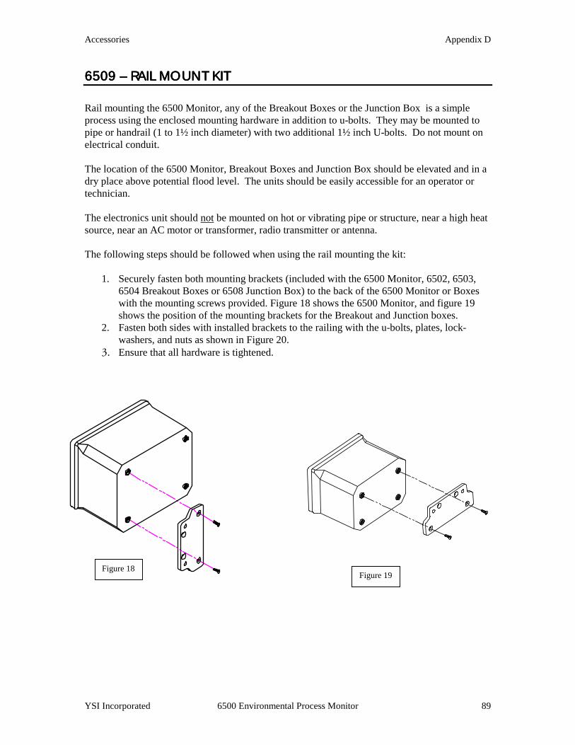
Accessories Appendix D
YSI Incorporated 6500 Environmental Process Monitor 89
6509 6509 6509 6509 –––– RAIL MOUNT KI RAIL MOUNT KI RAIL MOUNT KI RAIL MOUNT KITTTT Rail mounting the 6500 Monitor, any of the Breakout Boxes or the Junction Box is a simple process using the enclosed mounting hardware in addition to u-bolts. They may be mounted to pipe or handrail (1 to 1½ inch diameter) with two additional 1½ inch U-bolts. Do not mount on electrical conduit. The location of the 6500 Monitor, Breakout Boxes and Junction Box should be elevated and in a dry place above potential flood level. The units should be easily accessible for an operator or technician. The electronics unit should not be mounted on hot or vibrating pipe or structure, near a high heat source, near an AC motor or transformer, radio transmitter or antenna. The following steps should be followed when using the rail mounting the kit:
1. Securely fasten both mounting brackets (included with the 6500 Monitor, 6502, 6503, 6504 Breakout Boxes or 6508 Junction Box) to the back of the 6500 Monitor or Boxes with the mounting screws provided. Figure 18 shows the 6500 Monitor, and figure 19 shows the position of the mounting brackets for the Breakout and Junction boxes.
2. Fasten both sides with installed brackets to the railing with the u-bolts, plates, lock-washers, and nuts as shown in Figure 20.
3. Ensure that all hardware is tightened.
Figure 18 Figure 19
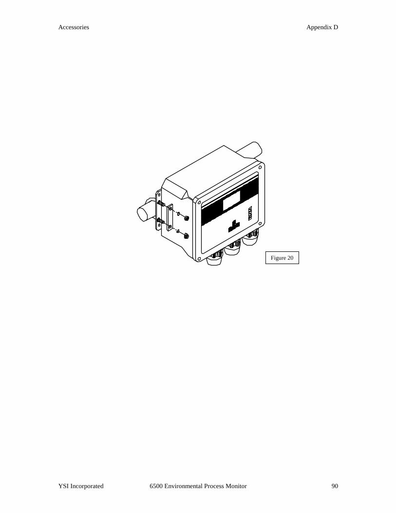
Accessories Appendix D
YSI Incorporated 6500 Environmental Process Monitor 90
Figure 20
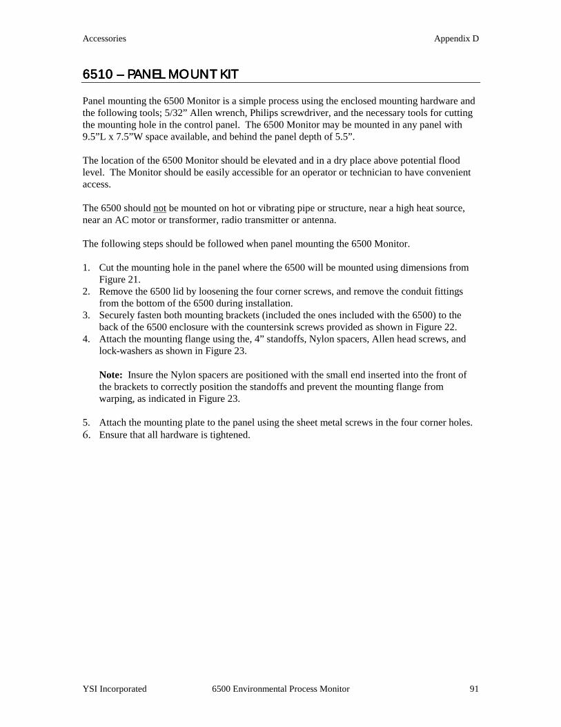
Accessories Appendix D
YSI Incorporated 6500 Environmental Process Monitor 91
6510 6510 6510 6510 –––– PANEL MOUNT K PANEL MOUNT K PANEL MOUNT K PANEL MOUNT KITITITIT Panel mounting the 6500 Monitor is a simple process using the enclosed mounting hardware and the following tools; 5/32” Allen wrench, Philips screwdriver, and the necessary tools for cutting the mounting hole in the control panel. The 6500 Monitor may be mounted in any panel with 9.5”L x 7.5”W space available, and behind the panel depth of 5.5”. The location of the 6500 Monitor should be elevated and in a dry place above potential flood level. The Monitor should be easily accessible for an operator or technician to have convenient access. The 6500 should not be mounted on hot or vibrating pipe or structure, near a high heat source, near an AC motor or transformer, radio transmitter or antenna. The following steps should be followed when panel mounting the 6500 Monitor. 1. Cut the mounting hole in the panel where the 6500 will be mounted using dimensions from
Figure 21. 2. Remove the 6500 lid by loosening the four corner screws, and remove the conduit fittings
from the bottom of the 6500 during installation. 3. Securely fasten both mounting brackets (included the ones included with the 6500) to the
back of the 6500 enclosure with the countersink screws provided as shown in Figure 22. 4. Attach the mounting flange using the, 4” standoffs, Nylon spacers, Allen head screws, and
lock-washers as shown in Figure 23.
Note: Insure the Nylon spacers are positioned with the small end inserted into the front of the brackets to correctly position the standoffs and prevent the mounting flange from warping, as indicated in Figure 23.
5. Attach the mounting plate to the panel using the sheet metal screws in the four corner holes. 6. Ensure that all hardware is tightened.

Accessories Appendix D
YSI Incorporated 6500 Environmental Process Monitor
Figure 21
Figure 22
Countersink Screws92
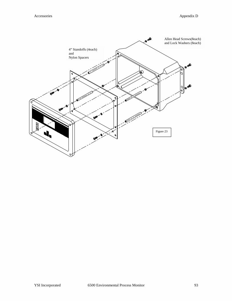
Accessories Appendix D
YSI Incorporated
Allen Head Screws(8each) and Lock Washers (8each)
4” Standoffs (4each) and Nylon Spacers
6500 Environmental Process Monitor 93
Figure 23

Accessories Appendix D
YSI Incorporated 6500 Environmental Process Monitor 94
6511 6511 6511 6511 –––– SONDE MOUNT K SONDE MOUNT K SONDE MOUNT K SONDE MOUNT KIT FOR 6OO SERIES SOIT FOR 6OO SERIES SOIT FOR 6OO SERIES SOIT FOR 6OO SERIES SONDESNDESNDESNDES The 6511 Sonde Mount Kit enables a 600 Series Sonde to be deployed in a permanently mounted two-inch schedule 40 PVC tube, which is not included in kit, approximately 10 feet in length. The tube is mounted to 1-1½” diameter railing by included brackets and u-bolts. The sonde will be deployed by gently sliding it down the tube, where it will rest on a stop cap at the end of the tube. The probes and probe guard will protrude through a hole in the stop cap at the end of the tube. The 6511 Kit should not be mounted on hot or vibrating pipes or structures, or near high heat sources, AC motors or transformers, radio transmitters or antennas. Do not mount on electrical conduit. Avoid routing Sonde cabling near wiring associated with rotating machinery and/or equipment involving electrical switching or regulation. Consider placing Sonde cables in grounded metallic conduit if unstable readings appear due to electromagnetic interference. The following steps should be followed when rail mounting the 6511 Sonde Mount Kit. 1. Using the Stop Cap as a guide, see Figure 24, position the adapter on the sonde so that the
probes, ports, and guard will protrude through stop cap when deployed, and securely tighten set screws. Note: Do not over-tighten the set screws or damage to the sonde body or adapter may occur.
2. Attach the stop cap to the end of
the PVC pipe using PVC cement, as per instructions on cement can label, ensuring that the stop cap is positioned straight and the pipe is fully inserted.
3. Loosely fasten two 1½” u-bolts
on each mounting plate to the railing, orientated as shown in Figure 25. 4. Loosely attach the 2” u-bolts to the mounting plates, orientated as shown in Figure 25. 5. Slide the uncapped end of the PVC pipe up through the 2” u-bolts until there is
approximately 1” of the PVC pipe above the upper mounting plate, and tighten 2” u-bolts. Note: Do not over tighten u-bolts or deformation of the PVC pipe may occur.
Schedule 40 PVC
Stop
Guard & Probe
Figure 23
Figure 24
Port & Guard
Stop Cap
Adapter Set Screw

Accessories Appendix D
YSI Incorporated 6500 Environmental Process Monitor 95
6. Tighten all remaining u-bolts to secure pipe.
7. Connect cable to the
Sonde and slowly slide the Sonde down the pipe until it rests on the Stop Cap.
8. Connect the cable to the
6500 Environmental Process Monitor or Breakout box. Figure 25
2” U-Bolts
Mounting Plates
1.5” U-Bolts
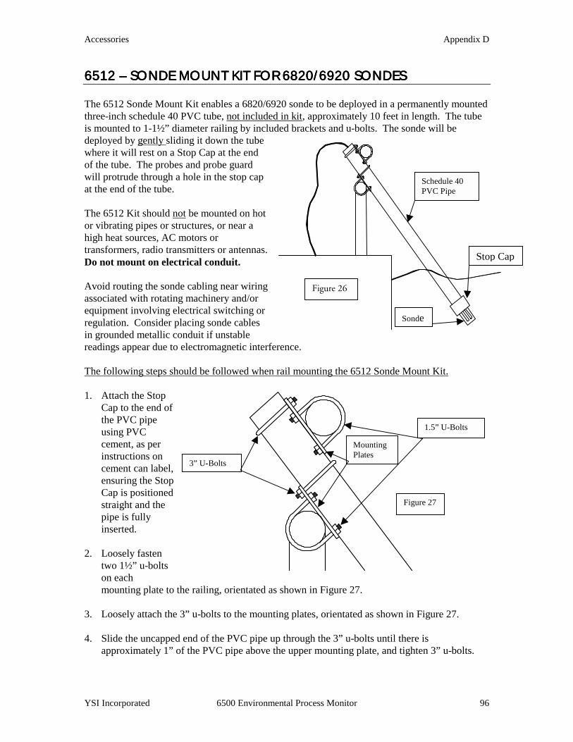
Accessories Appendix D
YSI Incorporated 6500 Environmental Process Monitor 96
6512 6512 6512 6512 –––– SONDE MOUNT K SONDE MOUNT K SONDE MOUNT K SONDE MOUNT KIT FOR 6820/6920 SONIT FOR 6820/6920 SONIT FOR 6820/6920 SONIT FOR 6820/6920 SONDESDESDESDES The 6512 Sonde Mount Kit enables a 6820/6920 sonde to be deployed in a permanently mounted three-inch schedule 40 PVC tube, not included in kit, approximately 10 feet in length. The tube is mounted to 1-1½” diameter railing by included brackets and u-bolts. The sonde will be deployed by gently sliding it down the tube where it will rest on a Stop Cap at the end of the tube. The probes and probe guard will protrude through a hole in the stop cap at the end of the tube. The 6512 Kit should not be mounted on hot or vibrating pipes or structures, or near a high heat sources, AC motors or transformers, radio transmitters or antennas. Do not mount on electrical conduit. Avoid routing the sonde cabling near wiring associated with rotating machinery and/or equipment involving electrical switching or regulation. Consider placing sonde cables in grounded metallic conduit if unstable readings appear due to electromagnetic interference. The following steps should be followed when rail mounting the 6512 Sonde Mount Kit. 1. Attach the Stop
Cap to the end of the PVC pipe using PVC cement, as per instructions on cement can label, ensuring the Stop Cap is positioned straight and the pipe is fully inserted.
2. Loosely fasten
two 1½” u-bolts on each mounting plate to the railing, orientated as shown in Figure 27.
3. Loosely attach the 3” u-bolts to the mounting plates, orientated as shown in Figure 27. 4. Slide the uncapped end of the PVC pipe up through the 3” u-bolts until there is
approximately 1” of the PVC pipe above the upper mounting plate, and tighten 3” u-bolts.
Schedule 40 PVC Pipe
Stop Cap
Sonde
Figure 26
Figure 27
3” U-Bolts
Mounting Plates
1.5” U-Bolts
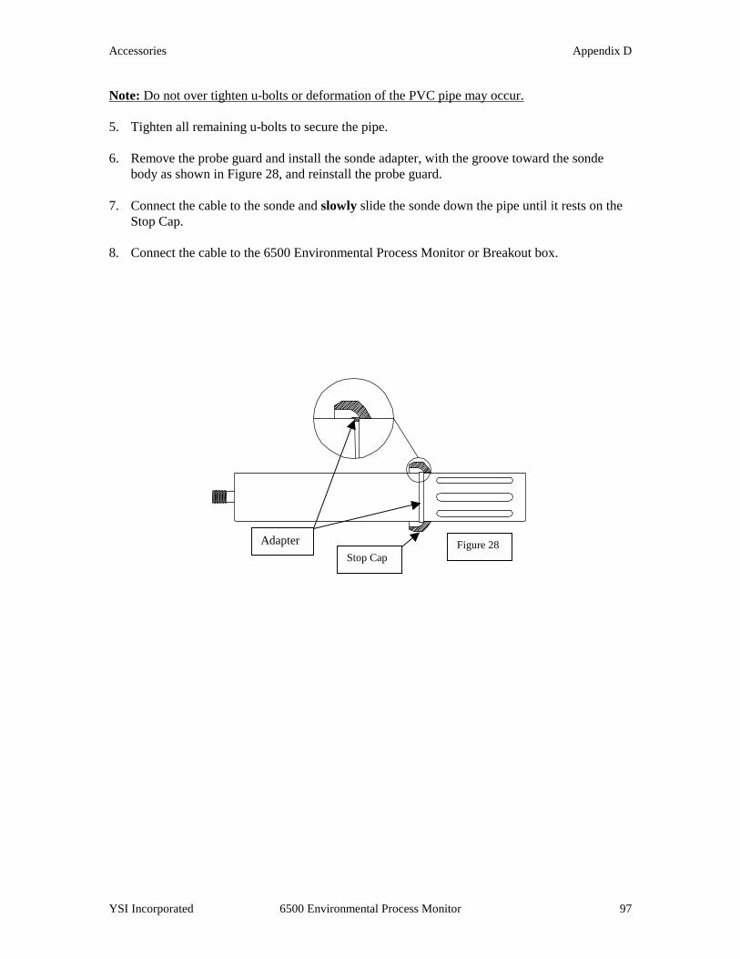
Accessories Appendix D
YSI Incorporated 6500 Environmental Process Monitor 97
Note: Do not over tighten u-bolts or deformation of the PVC pipe may occur. 5. Tighten all remaining u-bolts to secure the pipe. 6. Remove the probe guard and install the sonde adapter, with the groove toward the sonde
body as shown in Figure 28, and reinstall the probe guard. 7. Connect the cable to the sonde and slowly slide the sonde down the pipe until it rests on the
Stop Cap. 8. Connect the cable to the 6500 Environmental Process Monitor or Breakout box.
Figure 28 Stop Cap
Adapter

Accessories Appendix D
YSI Incorporated 6500 Environmental Process Monitor 98
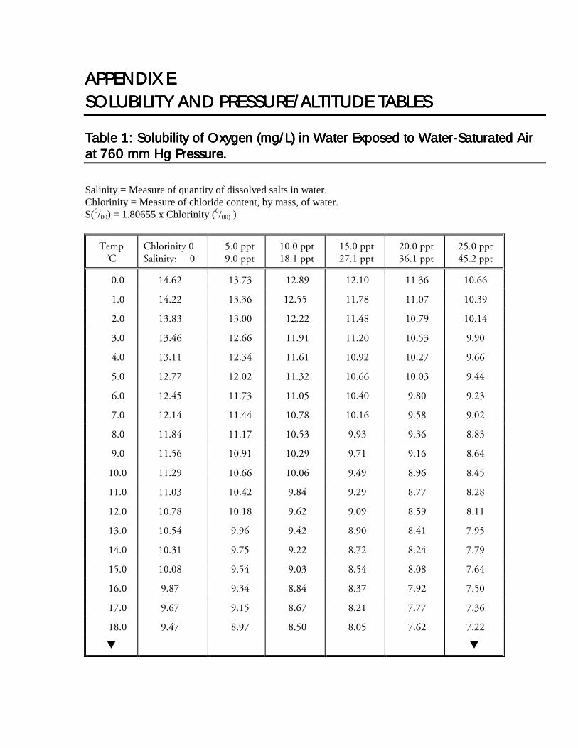
APPENDIX EAPPENDIX EAPPENDIX EAPPENDIX E SOLUBILITY AND PRESSSOLUBILITY AND PRESSSOLUBILITY AND PRESSSOLUBILITY AND PRESSURE/ALTITUDE TABLES URE/ALTITUDE TABLES URE/ALTITUDE TABLES URE/ALTITUDE TABLES
Table 1: Solubility of Oxygen (mg/L) in Water Exposed to WaterTable 1: Solubility of Oxygen (mg/L) in Water Exposed to WaterTable 1: Solubility of Oxygen (mg/L) in Water Exposed to WaterTable 1: Solubility of Oxygen (mg/L) in Water Exposed to Water----Saturated Air Saturated Air Saturated Air Saturated Air at 760 mm Hg Pressure.at 760 mm Hg Pressure.at 760 mm Hg Pressure.at 760 mm Hg Pressure.
Salinity = Measure of quantity of dissolved salts in water. Chlorinity = Measure of chloride content, by mass, of water. S(0/00) = 1.80655 x Chlorinity (0/00) )
Temp oC
Chlorinity 0 Salinity: 0
5.0 ppt 9.0 ppt
10.0 ppt 18.1 ppt
15.0 ppt 27.1 ppt
20.0 ppt 36.1 ppt
25.0 ppt 45.2 ppt
0.0 14.62 13.73 12.89 12.10 11.36 10.66
1.0 14.22 13.36 12.55 11.78 11.07 10.39
2.0 13.83 13.00 12.22 11.48 10.79 10.14
3.0 13.46 12.66 11.91 11.20 10.53 9.90
4.0 13.11 12.34 11.61 10.92 10.27 9.66
5.0 12.77 12.02 11.32 10.66 10.03 9.44
6.0 12.45 11.73 11.05 10.40 9.80 9.23
7.0 12.14 11.44 10.78 10.16 9.58 9.02
8.0 11.84 11.17 10.53 9.93 9.36 8.83
9.0 11.56 10.91 10.29 9.71 9.16 8.64
10.0 11.29 10.66 10.06 9.49 8.96 8.45
11.0 11.03 10.42 9.84 9.29 8.77 8.28
12.0 10.78 10.18 9.62 9.09 8.59 8.11
13.0 10.54 9.96 9.42 8.90 8.41 7.95
14.0 10.31 9.75 9.22 8.72 8.24 7.79
15.0 10.08 9.54 9.03 8.54 8.08 7.64
16.0 9.87 9.34 8.84 8.37 7.92 7.50
17.0 9.67 9.15 8.67 8.21 7.77 7.36
18.0 9.47 8.97 8.50 8.05 7.62 7.22
! !
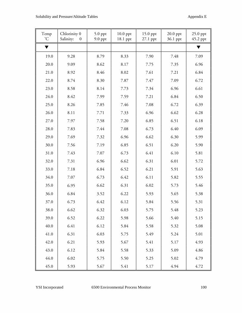
Solubility and Pressure/Altitude Tables Appendix E
YSI Incorporated 6500 Environmental Process Monitor 100
Temp oC
Chlorinity 0 Salinity: 0
5.0 ppt 9.0 ppt
10.0 ppt 18.1 ppt
15.0 ppt 27.1 ppt
20.0 ppt 36.1 ppt
25.0 ppt 45.2 ppt
! !
19.0 9.28 8.79 8.33 7.90 7.48 7.09
20.0 9.09 8.62 8.17 7.75 7.35 6.96
21.0 8.92 8.46 8.02 7.61 7.21 6.84
22.0 8.74 8.30 7.87 7.47 7.09 6.72
23.0 8.58 8.14 7.73 7.34 6.96 6.61
24.0 8.42 7.99 7.59 7.21 6.84 6.50
25.0 8.26 7.85 7.46 7.08 6.72 6.39
26.0 8.11 7.71 7.33 6.96 6.62 6.28
27.0 7.97 7.58 7.20 6.85 6.51 6.18
28.0 7.83 7.44 7.08 6.73 6.40 6.09
29.0 7.69 7.32 6.96 6.62 6.30 5.99
30.0 7.56 7.19 6.85 6.51 6.20 5.90
31.0 7.43 7.07 6.73 6.41 6.10 5.81
32.0 7.31 6.96 6.62 6.31 6.01 5.72
33.0 7.18 6.84 6.52 6.21 5.91 5.63
34.0 7.07 6.73 6.42 6.11 5.82 5.55
35.0 6.95 6.62 6.31 6.02 5.73 5.46
36.0 6.84 3.52 6.22 5.93 5.65 5.38
37.0 6.73 6.42 6.12 5.84 5.56 5.31
38.0 6.62 6.32 6.03 5.75 5.48 5.23
39.0 6.52 6.22 5.98 5.66 5.40 5.15
40.0 6.41 6.12 5.84 5.58 5.32 5.08
41.0 6.31 6.03 5.75 5.49 5.24 5.01
42.0 6.21 5.93 5.67 5.41 5.17 4.93
43.0 6.12 5.84 5.58 5.33 5.09 4.86
44.0 6.02 5.75 5.50 5.25 5.02 4.79
45.0 5.93 5.67 5.41 5.17 4.94 4.72

Solubility and Pressure/Altitude Tables Appendix E
YSI Incorporated 6500 Environmental Process Monitor 101
Table 2: Calibration Values Table 2: Calibration Values Table 2: Calibration Values Table 2: Calibration Values for Various Atmospheric Pressures and Altitudesfor Various Atmospheric Pressures and Altitudesfor Various Atmospheric Pressures and Altitudesfor Various Atmospheric Pressures and Altitudes
PRESSURE ALTITUDE CALIBRATION VALUE
Inches Hg mm Hg Millibars Feet Meters Percent Saturation 30.23 768 1023 -276 -84 101 29.92 760 1013 0 0 100 29.61 752 1003 278 85 99 29.33 745 993 558 170 98 29.02 737 983 841 256 97 28.74 730 973 1126 343 96 28.43 722 963 1413 431 95 28.11 714 952 1703 519 94 27.83 707 942 1995 608 93 27.52 699 932 2290 698 92 27.24 692 922 2587 789 91 26.93 684 912 2887 880 90 26.61 676 902 3190 972 89 26.34 669 892 3496 1066 88 26.02 661 882 3804 1160 87 25.75 654 871 4115 1254 86 25.43 646 861 4430 1350 85 25.12 638 851 4747 1447 84 24.84 631 841 5067 1544 83 24.53 623 831 5391 1643 82 24.25 616 821 5717 1743 81 23.94 608 811 6047 1843 80 23.62 600 800 6381 1945 79 23.35 593 790 6717 2047 78 23.03 585 780 7058 2151 77 22.76 578 770 7401 2256 76 22.44 570 760 7749 2362 75 22.13 562 750 8100 2469 74 21.85 555 740 8455 2577 73 21.54 547 730 8815 2687 72 21.26 540 719 9178 2797 71 20.94 532 709 9545 2909 70 20.63 524 699 9917 3023 69 20.35 517 689 10293 3137 68 20.04 509 679 10673 3253 67 19.76 502 669 11058 3371 66

Solubility and Pressure/Altitude Tables Appendix E
YSI Incorporated 6500 Environmental Process Monitor 102
Table 3: ConverTable 3: ConverTable 3: ConverTable 3: Conversion Factors for Feet/Meters, Celsius/Fahrenheit, mg/L/ppmsion Factors for Feet/Meters, Celsius/Fahrenheit, mg/L/ppmsion Factors for Feet/Meters, Celsius/Fahrenheit, mg/L/ppmsion Factors for Feet/Meters, Celsius/Fahrenheit, mg/L/ppm
TO CONVERT FROM TO EQUATION
Feet Meters Multiply by 0.305
Meters Feet Multiply by 3.28
Degrees Celsius Degrees Fahrenheit 5/9×(oF-32)
Degrees Fahrenheit Degrees Celsius 9/5×(oC)+32
Milligrams per liter (mg/L) Parts per million (ppm) Multiply by 1
Table 4. Conversion Factors for Common Units of PressureTable 4. Conversion Factors for Common Units of PressureTable 4. Conversion Factors for Common Units of PressureTable 4. Conversion Factors for Common Units of Pressure
kilo Pascals mm Hg millibars inches H20 PSI inches Hg
1 atm 101.325 760.000 1013.25 406.795 14.6960 29.921 1 kiloPascal 1.00000 7.50062 10.0000 4.01475 0.145038 0.2953 1 mmHg 0.133322 1.00000 1.33322 0.535257 0.0193368 0.03937 1 millibar 0.100000 0.750062 1.00000 0.401475 0.0145038 0.02953 1 inch H20 0.249081 1.86826 2.49081 1.00000 .0361 0.07355 1 PSI 6.89473 51.7148 68.9473 27.6807 1.00000 2.0360 1 inch Hg 3.38642 25.4002 33.8642 13.5956 0.49116 1.00000 1 hectoPascal 0.100000 0.75006 1.00000 0.401475 0.0145038 0.02953 1 cm H20 0.09806 0.7355 9.8 x 10⁻⁷ 0.3937 0.014223 0.02896
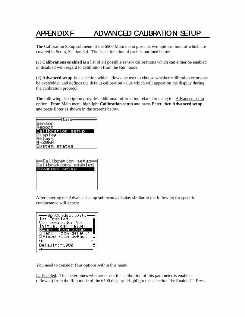
APPENDIX FAPPENDIX FAPPENDIX FAPPENDIX F ADVANCEDADVANCEDADVANCEDADVANCED CALIBRATION SETUP CALIBRATION SETUP CALIBRATION SETUP CALIBRATION SETUP The Calibration Setup submenu of the 6500 Main menu presents two options, both of which are covered in Setup, Section 3.4. The basic function of each is outlined below. (1) Calibrations enabled is a list of all possible sensor calibrations which can either be enabled or disabled with regard to calibration from the Run mode. (2) Advanced setup is a selection which allows the user to choose whether calibration errors can be overridden and defines the default calibration value which will appear on the display during the calibration protocol. The following description provides additional information related to using the Advanced setup option. From Main menu highlight Calibration setup and press Enter, then Advanced setup and press Enter as shown in the screens below.
After entering the Advanced setup submenu a display similar to the following for specific conductance will appear.
You need to consider four options within this menu. Is: Enabled. This determines whether or not the calibration of this parameter is enabled (allowed) from the Run mode of the 6500 display. Highlight the selection “Is: Enabled”. Press
Advanced Calibration Setup Appendix F
YSI Incorporated 6500 Environmental Process Monitor 104
Enter to toggle back and forth between “Is: Enable” and “Is: Disabled”. Select the desired option. Can override: Yes. This determines whether or not an error message can be overridden if it occurs during the calibration procedure. Highlight the “Can override: Yes” selection. Press Enter to toggle back and forth between “Can override: Yes” and “Can override: No”. Select the desired option. Remember that a calibration error message may indicate a significant malfunction of the 600 Sonde sensor which in turn indicates that service to that sensor is required if accurate readings are to be obtained. Therefore, it is usually proper to select the “No” option with regard to this selection. There are occasions when the user is aware that the error message is due to special circumstances and thus the “Yes” option is appropriate, but these are rare. Generally, calibration errors should only be overridden after consulting with YSI authorized service personnel. Vari from Probe, Vari from Default or Fixed from Default. The software allows you to choose only one of these three choices. This choice defines the default parameter value which appears on the 6500 display when the calibration procedure is initiated. During setup choose “Vari from Probe”. With this selection, the current reading of the parameter will be displayed on calibration startup and this value can be varied from the 6500 keyboard to reflect the true value. The other two selections offer the user flexibility for special circumstances. If “Vari from Default” is selected, then the default value (which can be entered on the final line of this submenu display) will appear on calibration initiation for this parameter. You might select this option if you always calibrate specific conductance at approximately 10 mS/cm, and then “10.0” mS/cm (10,000 uS/cm) will appear on the screen when calibration of this parameter begins. As with the “Vari from Probe” option, you can modify the value on the screen using the 6500 arrow keys to reflect the true specific conductance. Note, however, that the benefit is usually slight compared to using the actual sensor reading under “Vari from Probe”. You would consider choosing “Fixed form Default” if you always calibrate specific conductance at 10 uS/cm and are certain that this is the true value. In this case 10 mS/cm (10,000 uS/cm) will appear on the screen for the calibration protocol and you will not be able to change this value from the 6500 arrow keys. Default = 1000. The value of the default calibration value for this parameter is only needed if you choose either the “Vari from Default” or “Fixed from Default” options above. In the example shown 1000 shows up as the default value. Depending on units, this could represent 1000 uS/cm, for example. If you choose “Vari from Probe”, you need not set a value here. To view other parameters and set up their associated calibration choices, use the right and left arrow keys to scroll horizontally between parameters using the scroll bar at the bottom of the screen (see screen above). Use the descriptions above to set each of the 4 options for these other parameters. After configuring your sensor calibrations as described above, press Esc to return to the Main menu of the 6500 Monitor.

APPENDIX GAPPENDIX GAPPENDIX GAPPENDIX G INDEXINDEXINDEXINDEX 4 4-20 MA Current Loop Output Problems 58 4-20 MA Current Loop Output Wiring 14 6 6-Series Sonde Setup 20
Sensor 22 Report 22
6500 Calibration Waning and Error Messages 42 6500 Menu Choice Problems 55 6500 Monitor Features 1 6500 Monitor Setup 23
Calibration Setup 24 Display Setup 26 4-20 MA Channel Setup 31 Multiple Sonde Setup 28 Relays 29 System Status 35
6502 Breakout Box 76 Wall Mounting 76 Rail Mounting 77 Wiring Instructions 77 Sonde Cable Connections 78 6503 Breakout Box 80 Wall Mounting 80 Rail Mounting 81 6504 Breakout Box 82 Wall Mounting 82 Rail Mounting 82 Wiring Instructions 83 Sonde Cable Connections 83 6505 Weather Shield 85 Wall Mounting 85 Rail Mounting 85 6508 Junction Box 87 Wall Mounting 87 Rail Mounting 87 Wiring Instructions 88 Sonde Cable Connections 88 6509 Rail Mount Kit 89 6510 Panel Mount Kit 91 6511 Sonde Mount Kit for 600 Series Sondes 94 6512 Sonde Mount Kit for 6820/6920 Sondes 96
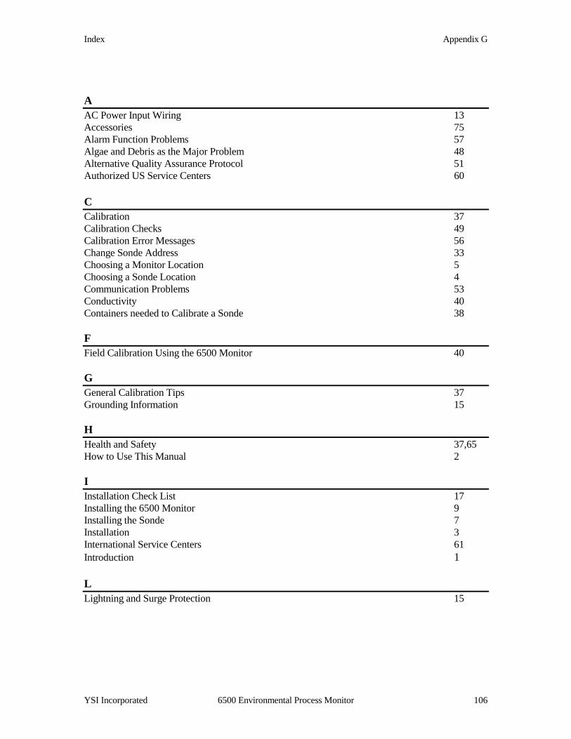
Index Appendix G
YSI Incorporated 6500 Environmental Process Monitor 106
A AC Power Input Wiring 13 Accessories 75 Alarm Function Problems 57 Algae and Debris as the Major Problem 48 Alternative Quality Assurance Protocol 51 Authorized US Service Centers 60 C Calibration 37 Calibration Checks 49 Calibration Error Messages 56 Change Sonde Address 33 Choosing a Monitor Location 5 Choosing a Sonde Location 4 Communication Problems 53 Conductivity 40 Containers needed to Calibrate a Sonde 38 F Field Calibration Using the 6500 Monitor 40 G General Calibration Tips 37 Grounding Information 15 H Health and Safety 37,65 How to Use This Manual 2 I Installation Check List 17 Installing the 6500 Monitor 9 Installing the Sonde 7 Installation 3 International Service Centers 61 Introduction 1 L Lightning and Surge Protection 15

Index Appendix G
YSI Incorporated 6500 Environmental Process Monitor 107
M Minimizing the effect of algae and debris 48 Modbus Implementation 44 Modbus Setup 32,47 Multiple Sonde Calibration 37 Multiple Sonde Problems 54 Multiple Sonde Setup 28,33 O Optional Accessories for the 6500 Monitor 75 Optional Accessories for 6-Series Sonde 75 P Proper Use and Care of the 6500 System 43 Q Quality Assurance 47 R Rail Mount Option 8 Recommended Cleaning of the 6500 Monitor and Accessories 52 Recommended Monthly Maintenance of the DO Probe 51 Recommended Quality Assurance Protocol 49 Recommended Volumes for use with the Calibration Cup 39 Relay Output Wiring 14 Required Notice 73 RS232 and RS485 Terminals 14 S Safety Issues 15 Sealants, Dessicants and Securing the Monitor 16 Selecting an Installation Location 3 Sensor Accuracy and Repeatability Problems 56 Solubility and Pressure/Altitude Tables 99 Sonde Cable Connections 11 Sonde Maintenance at the Deployment Site 48 Specifications 63 System Configuration 19 System Setup 19 T Tips for Good Calibration 38 Troubleshooting 53
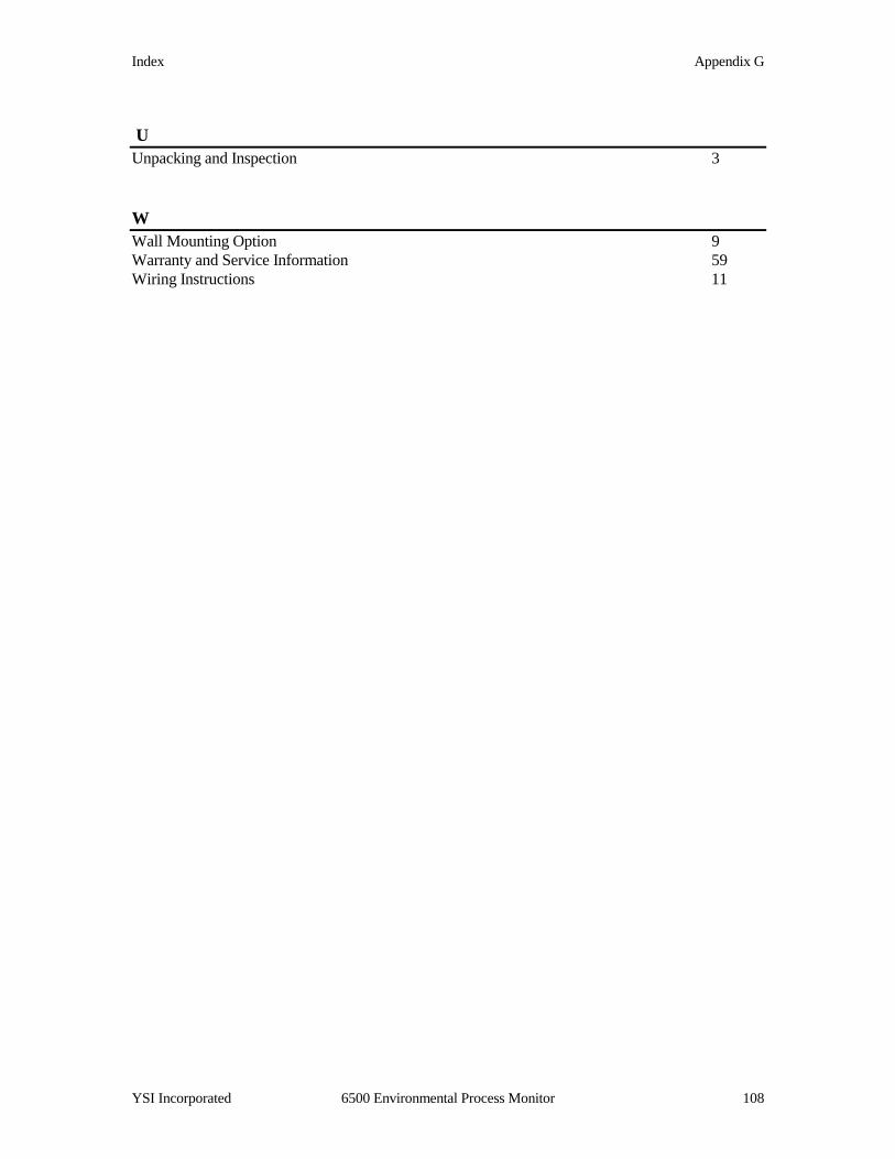
Index Appendix G
YSI Incorporated 6500 Environmental Process Monitor 108
U Unpacking and Inspection 3 W Wall Mounting Option 9 Warranty and Service Information 59 Wiring Instructions 11

YSI, Incorporated 6500 Environmental Process Monitor 109
Item # 065902 DRW # A65902E
August 1999
1725 Brannum Lane Yellow Springs, Ohio 45387 USA (800) 897-4151 (937) 767-7241 FAX (937) 767-9353
E-mail: [email protected] Website: http://www.YSI.com