ysi 650 sonde – introduction · web viewc port is for the optical chlorophyll sensor (model ysi...
TRANSCRIPT
YSI 6600 Sonde
Instruction Manual
Version 1
1

Contents
YSI 6600 Sonde...........................................................................................4Introduction - What is a Sonde?...................................................................................4What parameters does the sonde measure?................................................................4Important Points to Remember.....................................................................................5Initial Setup...................................................................................................................6
Installing Batteries in the Sonde............................................................................6Installing Sensors..................................................................................................7
Optical Sensors.................................................................................................9Regular Sensors................................................................................................9
Installing Probe Guard or Calibration Cup...........................................................10
YSI 650 MDS Display Unit.........................................................................11Installing Batteries in the 650 Display Unit.................................................................11Connecting the Sonde to the YSI 650 Display Unit....................................................11Initial Setup.................................................................................................................13
Communication between the 650 display unit and the sonde.................................15Main Menu..............................................................................................................16
System setup.......................................................................................................16Date and Time.................................................................................................16Barometer Calibration......................................................................................17The Power Sonde Option.................................................................................18
Sonde menu........................................................................................................19
Calibrating Sonde Sensors.........................................................................19Calibrating a clean or new sonde...............................................................................20
Supplies required....................................................................................................20Calibration Instructions...........................................................................................20
1. Dissolved Oxygen...........................................................................................202. Depth...............................................................................................................213. Conductivity and Temperature........................................................................214. pH....................................................................................................................235. Oxidation Reduction Potential (ORP)..............................................................246. Chlorophyll......................................................................................................257. Turbidity...........................................................................................................26
Calibration Sheet....................................................................................................28Logging data – setting up the calibrated sonde to be deployed.................................29
After a Sonde Deployment – Retrieving the sonde, downloading the data and checking for drift..................................................................................30
Sonde retrieval...........................................................................................................30Downloading Water Quality Data from the Sonde to a Computer..............................30After deployment check for drift..................................................................................32
Supplies needed to check for drift:..........................................................................33
2

Instructions - checking for drift................................................................................331. Turbidity and DO.............................................................................................332. Conductivity and Temperature........................................................................343. pH....................................................................................................................344. Oxidation Reduction Potential.........................................................................345. Depth...............................................................................................................34
Cleaning the Sonde....................................................................................................35Re-Calibration and Re-deployment............................................................................35Sensor Storage...........................................................................................................35Quality Control............................................................................................................35
References.................................................................................................35
Please see the video associated with this manual for visual demonstrations of the procedures presented in this manual. The video times associated with the different manual sections are as follows:
0:03 An Introduction to the YSI Sonde (pg.4)0:24 Installing batteries in the 650 Display Unit (pg.11)2:38 Installing batteries in the Sonde (pg.6)5:34 Installing sensors and removing plugs (pg.7)6:50 The Bulkhead (pg.8)8:13 Installing Optical Sensors (pg.9)10:07 Installing Regular Sensors (pg.9)13:30 Installing Probe Guard and Calibration Cup (pg.10)14:52 Connecting the Sonde to the 650 MDS Display Unit (pg.11)17:23 Calibrating Dissolved Oxygen (pg.20)22:34 Calibrating Depth (pg.21)24:16 Calibrating Conductivity and Temperature (pg.21)33:32 Calibrating pH (pg.23)44:54 Calibrating ORP (pg.24)47:51 Calibrating Chlorophyll (pg.25)49:47 Calibrating Turbidity (pg.26)
3

YSI 6600 Sonde
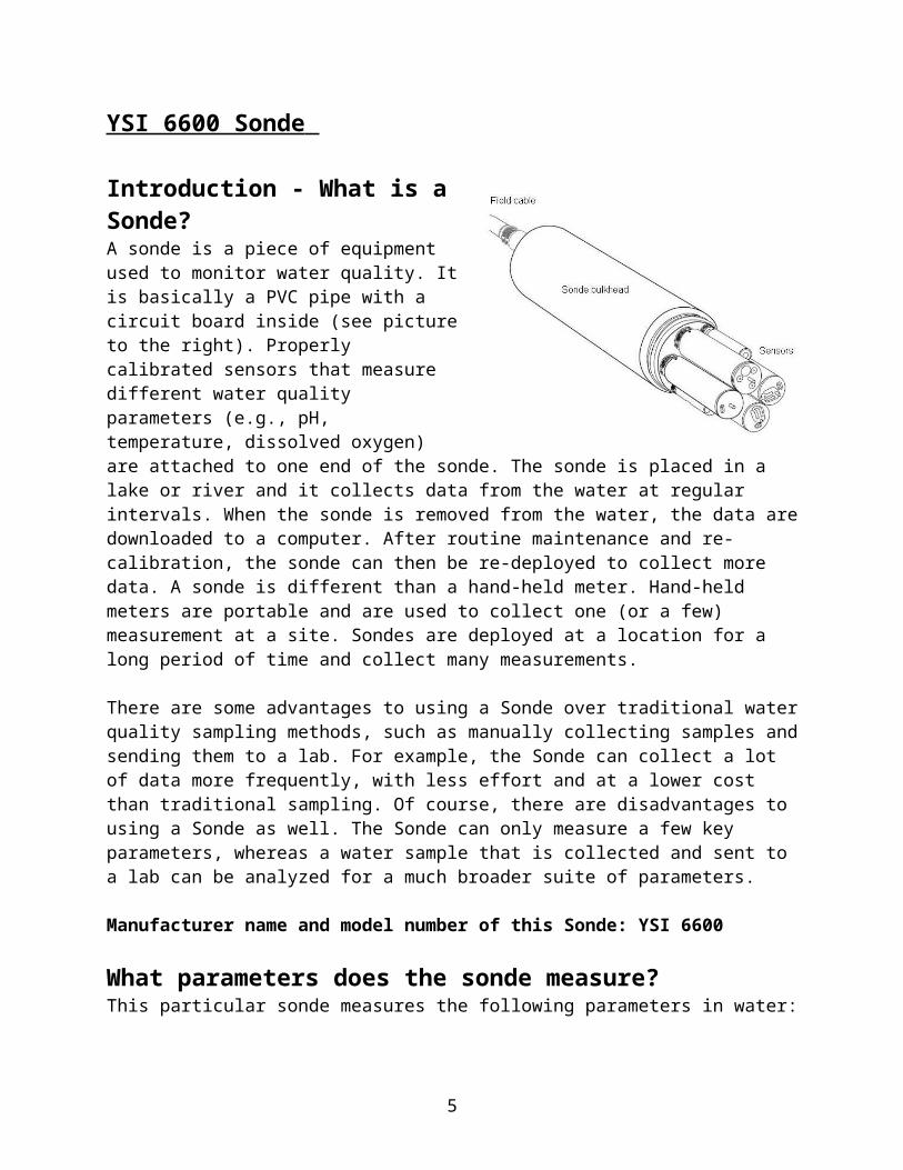
Introduction - What is a Sonde?A sonde is a piece of equipment used to monitor water quality. It is basically a PVC pipe with a circuit board inside (see picture to the right). Properly calibrated sensors that measure different water quality parameters (e.g., pH, temperature, dissolved oxygen) are attached to one end of the sonde. The sonde is placed in a lake or river and it collects data from the water at regular intervals. When the sonde is removed from the water, the data are downloaded to a computer. After routine maintenance and re-calibration, the sonde can then be re-deployed to collect more data. A sonde is different than a hand-held meter. Hand-held meters are portable and are used to collect one (or a few) measurement at a site. Sondes are deployed at a location for a long period of time and collect many measurements.
There are some advantages to using a Sonde over traditional water quality sampling methods, such as manually collecting samples and sending them to a lab. For example, the Sonde can collect a lot of data more frequently, with less effort and at a lower cost than traditional sampling. Of course, there are disadvantages to using a Sonde as well. The Sonde can only measure a few key parameters, whereas a water sample that is collected and sent to a lab can be analyzed for a much broader suite of parameters.
Manufacturer name and model number of this Sonde: YSI 6600
What parameters does the sonde measure? This particular sonde measures the following parameters in water:
1) Temperature (in degrees Celcius)2) Conductivity3) pH4) Oxidation/Reduction Potential (ORP)5) Dissolved Oxygen6) Turbidity7) Chlorophyll
For general background information on these parameters and why it is important for us to measure them, please see the attached Water Quality Fact Sheets.
4
Important Points to Remember
1) The electronics inside the Sonde are easily damaged by water!!! It is very important that water and other solutions are NEVER allowed to enter the PVC body of the sonde. Ensure that all sensors, plugs and the cap that covers the cable port are properly installed at all times.
2) It is very important to maintain the rubber O-rings on the sensors and caps. Whenever a sensor, plug or cap is removed for cleaning or servicing, dirt on these O-rings should be cleaned away gently. Before sensors, plugs, or caps are replaced, put a little dab of Krytox (included with the Sonde) on the O-rings (just use enough so that it appears shiny, NOT goopy). O-rings should be replaced every one to two years to ensure they keep a good watertight seal.
3) Make sure the batteries inside the sonde have sufficient charge before deployment (see discussion of calculated sonde battery life on page 27 of this manual). The sonde cannot collect data without battery power.
4) The end of the optical dissolved oxygen sensor must always be stored in a moist environment when it is not in use. If it is detached from the sonde, it should be stored with a moist sponge inside its flexible plastic black cap.
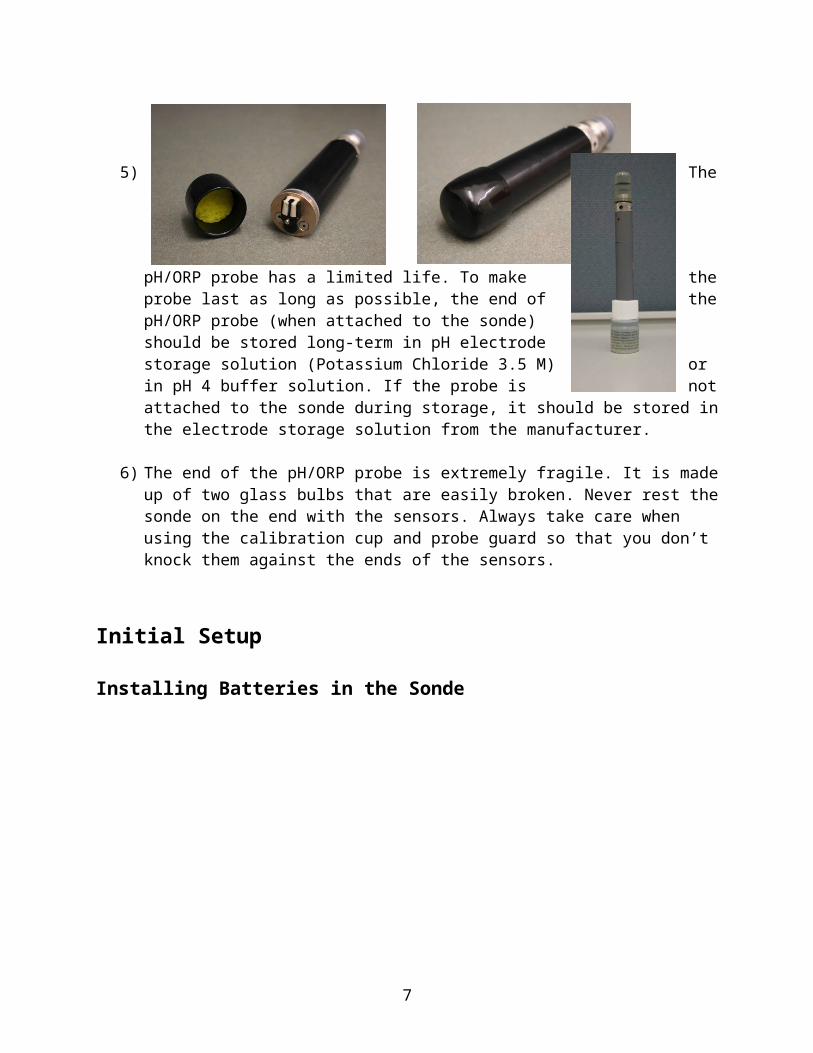
5) The pH/ORP probe has a limited life. To make the probe last as long as possible, the end of the
pH/ORP probe (when attached to the sonde) should be stored long-term in pH electrode storage solution (Potassium Chloride 3.5 M) or in pH 4 buffer solution. If the probe is not attached to the sonde during storage, it should be stored in the electrode storage solution from the manufacturer.
6) The end of the pH/ORP probe is extremely fragile. It is made up of two glass bulbs that are easily broken. Never rest the sonde on the end with the sensors. Always take care when using the calibration cup and probe guard so that you don’t knock them against the ends of the sensors.
5

Initial Setup
Installing Batteries in the Sonde
Batteries provide the power for the sonde to collect and store data when it is deployed in the water. Make sure that the sonde contains fresh batteries before it is deployed or no data will be collected! This sonde takes 8 C type alkaline batteries. Carry spare batteries.
Step 1) Using the hex tool, loosen the battery lid screws.
Step 2) Remove the lid and install the batteries as shown to the left. Ensure that they have the proper orientation.
Step 3) Before replacing the lid, it is important to ensure that the orange O-ring is seated completely within the groove on the underside of the lid. Press around all its edges to make sure it is not popping out of the groove anywhere along its length. Small retaining tabs along the O-ring help keep it inside the groove. There is a detailed description of how to properly seat this orange O-ring on pages 2-19 to 2-20 of the YSI instruction manual. Do not lubricate the orange O-ring, but make sure it is clean.
Step 4) Make sure that the black O-rings that encircle the lid are completely clean. No dirt
should be present on or under any of these O-rings. Apply a small amount of Krytox to the black O-rings so that they are shiny.
6
Step 5) Put the lid back on the battery compartment in the orientation showed to the left and tighten the screws until snug. Do not
overtighten the screws!
If the batteries have been properly installed, the voltage should read 12.0 volts or higher in the sonde Status Menu. Remove batteries from the sonde when not in use (i.e., for long-term storage). The battery compartment of this sonde has a lid with a round pressure-release safety valve. In the highly unlikely event that the batteries should malfunction and de-gas, this valve will release any pressure building up in the battery compartment. If the valve ever opens, the battery compartment lid must be replaced with a new one from the manufacturer before the sonde can be used again.
Installing Sensors
To prepare the sonde for calibration and data collection, you need to install probes (also called sensors) into the ports on the sonde bulkhead. When initially received from the manufacturer, there are screw-in plugs in the ports to protect the port connections from damage. Do not discard these plugs! Save all plugs for future use.
Step 1: Remove plugs from ports
Plugs are removed by inserting the long end of the installation tool into the holes in the plug tops and gently unscrewing. The installation tool can be found in the maintenance kit (YSI 6570).
**Always remove plugs and sensors from the sonde with that end of the sonde pointed towards the ground or floor (i.e., oriented as in the picture below).** If there is water present on the sensors or plugs, removing them as they are pointed down will allow water to drain away and prevent any flow of water up into the electrical connections inside the ports.
7

Step 2: Install Sensors
This sonde has two different types of ports capable of accepting sensors:
Optical ports There are four optical ports on this sonde labelled as O, B, C and T. O port is for the optical Dissolved Oxygen sensor (model YSI 6150)C port is for the optical Chlorophyll sensor (model YSI 6136)T port is for the optical Turbidity sensor (model YSI 6025)B port currently has no optical sensor, so it is Blank for now
Regular portsThere are two regular ports. They are not labeled, but they are different:1) The 6-pin port is for the Temperature/Conductivity sensor (model YSI 6560)2) The 4-pin port is for the pH/Oxidation Reduction Potential sensor (model YSI 6569)
8

Before inserting any sensor, ensure that the port is free of moisture! Use a clean lint-free cloth to dry if necessary.
Ensure that the O-ring on the sensor you are inserting is completely clean of dirt. Dirt will allow a path for water to enter the electronics of the Sonde when it is deployed.
Apply a very light sheen of Krytox to the clean O-ring right before the sensor is installed to keep it in good shape. Optical Sensors: Install the optical sensors before you install the regular sensors.
Step 1) Insert the sensor into the appropriate port and gently rotate until the pins of the connectors are aligned.
Step 2) Slowly finger-tighten the nut down toward the bulkhead. **During this step, be careful not to cross thread the nuts! If you meet resistance while finger-tightening, STOP, back out and begin the process again!**
Step 3) Finish tightening using the short end of the installation tool so that the seal is waterproof. Do not overtighten. When tightened properly, it is normal for there to still be a 1-2 mm gap between the nut of the optical sensor and the body of the bulkhead.
9

Regular Sensors: Install after the optical sensors.
Step 1) Insert the sensor into the appropriate port and gently rotate until the pins of the connectors are aligned.
Step 2) Push the sensor inward so that it seats in the port snugly. Slowly finger-tighten the nut down toward the bulkhead. **During this step, be careful not to cross thread the nuts! If you meet resistance while finger-tightening, STOP, back out and begin the process again!**
Step 3) Use the long end of the installation tool to tighten the nut an additional quarter turn until snug. Do not overtighten. When tightened properly, there should be no space between the nut of the regular sensor and the body of the bulkhead.
Installing Probe Guard or Calibration Cup
The probe guard protects the sensors during deployment and allows water to flow over the sensors. Once all the probes are correctly installed and calibrated, screw the guard onto the sonde by aligning the threads and turning clockwise until the guard is securely attached.
10

The calibration cup is used during sensor calibration and for long-term storage when the sonde is not in use. It is a solid plastic cup. The calibration cup is installed in exactly the same way as the probe guard.
YSI 650 MDS Display Unit
The YSI 650 MDS display unit is an instrument that allows the user to tell the sonde what parameters to measure and how often to make water quality measurements when it is deployed in water. The display unit is also used during calibration of the sonde.
Installing Batteries in the 650 Display Unit
11

The YSI 650 display unit requires 4 C type batteries. Change the batteries in a dry environment. Carry spare batteries.
Step 1) Loosen the 4 screws on the battery compartment lid using a screwdriver and remove the lid completely. **Notice the four small holes on the lid. Barometric Pressure is read through these four holes. Never cover them with tape or stickers or push anything through these holes (e.g., pins).**
Step 2) Insert the batteries between the clips, being sure that the orientation is correct. A foam pad on the back of the lid will help to hold the batteries in place when the lid is put back on.
Step 3) Re-install the battery lid and tighten the screws. Do not overtighten.
Connecting the Sonde to the YSI 650 Display Unit
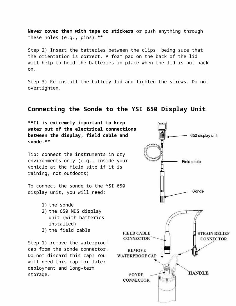
**It is extremely important to keep water out of the electrical connections between the display, field cable and sonde.**
Tip: connect the instruments in dry environments only (e.g., inside your vehicle at the field site if it is raining, not outdoors)
To connect the sonde to the YSI 650 display unit, you will need:
1) the sonde2) the 650 MDS display unit
(with batteries installed)3) the field cable
Step 1) remove the waterproof cap from the sonde connector. Do not discard this cap! You will need this cap for later deployment and long-term storage.
Step 2) connect the field cable to the sonde connector. There is a guide
12

inside the connection that ensures that the pins are properly lined up. Rotate the cable gently until the guide engages.
Step 3) Tighten the connector by turning clockwise. When connected properly, only two threads should be visible!
Step 4) Attach the strain relief connector to the metal handle and close the connector’s opening.
Step 5) At its other end, the field cable plugs directly into the 650 display module using an 8-pin connector. Line up the guides and pins inside the connector. Be careful not to cross-thread. Gently turn the nut clockwise until it clicks to lock the connector in place. Attach the second strain relief connector to the display unit.
Initial Setup
Your particular community’s sonde and 650 display unit have settings that are identical to those in all the other sondes and display units purchased by ENR for the other communities in the NWT. If all the communities work with the same instruments, settings and operating instructions, the water quality data generated at the different sites will be consistent and comparable. This will help to evaluate all the water quality data once it is collected. It is important for you to be able to access and understand these settings but under normal operation, they should not need to be changed. Here is a description of how to access the settings:
13

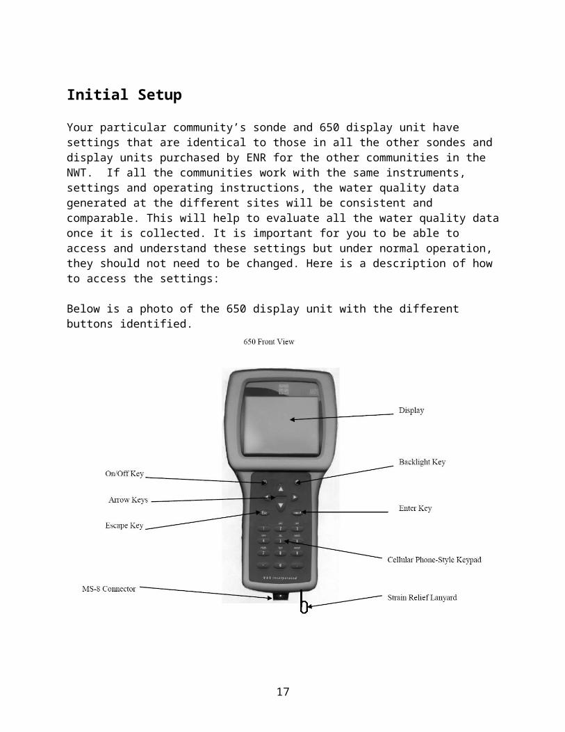
Below is a photo of the 650 display unit with the different buttons identified.
The Arrow Keys are used to move up and down through the different selections in the menus. The Enter key is used to confirm a selected menu item. The Escape (ESC) key is used to return to the previous screen you were at in the menu. The number buttons are used to enter words and data (for example site names). The following guide indicates the number of times you need to press each number button to access individual capital and lower case letters to spell out site names:
14
If you are finding that the screen is difficult to read, you can make the screen either darker or lighter by holding down the Backlight key and pressing either the up arrow (to darken) or the down arrow key (to lighten).
15

Communication between the 650 display unit and the sonde
Note: Make sure only two threads of the communications communications connector are visible once the cable has been attached. If more than two threads are showing after attaching the cable, water WILL get into the connection and potentially cause harm to the connector.
When physically connected together using the field cable, the 650 display unit and sonde can exist in two different communication states.
1) In the first state, the display unit is connected electronically to the sonde and basically “talking to” it. In this state, the small picture in the bottom right hand corner of the 650 display is a picture of the sonde. In this communication state, you can calibrate the sonde and change sonde settings.
2) In the second state, the display unit is not connected electronically to the sonde and is not “talking to it”. In this case, the icon in the bottom right hand corner of the 650 display will be the 650 display itself.
16
For the next few sections, we are just setting up the basic display unit itself, so we do not need to be connected to the sonde. When you are working with the instrument, make sure it is in the communication state you desire by checking the icon in the corner. Main Menu
After physically connecting the sonde to the display unit (as described in the previous sections), turn on the YSI 650 display unit using the green power button. Notice that in this picture you can see that we are not “talking” to the sonde. You will see the following Main Menu:
System setup
Date and Time
To set or change the date and time in the YSI 650 display unit:
Step 1: Select System setup from the main menu
17

Step 2: Select Date & time
Step 3: Select d/m/y as the date display formatStep 4: Ensure there is a check mark beside 4 digit yearStep 5: Enter the current date in the format d/m/yStep 6: Enter the current time.
**Note that it is critical that you keep track of the time zone the data is collected in and whether or not the time of the instrument was changed when the clocks are put forward and back for local daylight savings! Without good field records, it is very difficult to determine when data has been collected.**
Barometer Calibration
There is an option under System setup called Calibrate Barometer. The barometer in the 650 display unit should only ever be calibrated using local barometric pressure (i.e., pressure that has not been corrected for sea level). Local weather service barometric
18

pressure is often corrected to sea level and is therefore not the same as the true local barometric pressure value required by this instrument. New instruments are programmed to measure true local pressure and should remain stable for a long time before requiring re-calibration. If you do need to calibrate the barometer:
Step 1) Determine the local uncorrected barometric pressure. If there is no true, local laboratory barometer reading available, a weather service reading (in mm of Hg) that has been corrected to sea level can be “uncorrected” according to the following formula:
True BP = [sea-level corrected BP] – [2.5 x (local altitude in ft above sea level/100)]
Step 2) From the main menu, select System Setup then Calibrate BarometerStep 3) Input the local barometric pressure using the keypadStep 4) Press the enter key
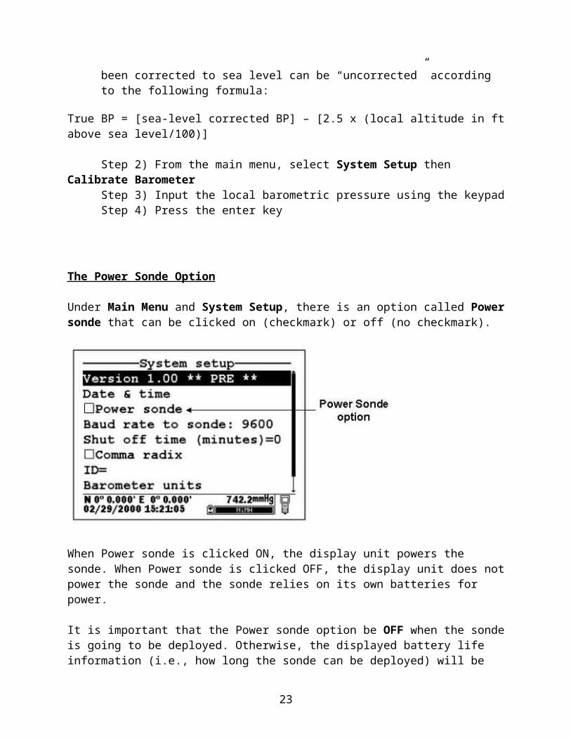
The Power Sonde Option
Under Main Menu and System Setup, there is an option called Power sonde that can be clicked on (checkmark) or off (no checkmark).
When Power sonde is clicked ON, the display unit powers the sonde. When Power sonde is clicked OFF, the display unit does not power the sonde and the sonde relies on its own batteries for power.
It is important that the Power sonde option be OFF when the sonde is going to be deployed. Otherwise, the displayed battery life information (i.e., how long the sonde can be deployed) will be incorrect and it is possible that the sonde will not be powered and will not store data when deployed. It is best to just ensure that both the display unit
19

and sonde have good batteries in them at all times and leave the Power sonde option OFF (no checkmark) at all times.
Sonde menu
Now that we have set up the 650 display unit, it is time to connect the display unit electronically to the sonde. From the 650 Main menu, select Sonde menu. A box with the word “connecting” will appear quickly and then disappear. The small picture in the bottom right hand corner of the 650 display will change to show a picture of the sonde. You are now in the menu system for the sonde. In this series of menus, you can calibrate the sonde and change sonde settings. You will now see the following menu:
The first screen you will see is the Main menu for the sonde. Do not confuse this menu with the main menu for the 650 display unit. Orient yourself using the icon in the bottom right corner if necessary. You can exit the sonde menu system from this screen by pressing the escape key. The sonde will disconnect electronically and you will be returned to the main menu of the 650 display unit.
Calibrating Sonde Sensors
Calibration is an important process that helps the user ensure that the sonde sensors are measuring properly and generating accurate water quality data. We basically have to train the sensors so that they ‘know’ how to measure the parameters we are
20

interested in. Calibration requires solutions (called standards) with known levels of the chemical parameters we will be measuring. We calibrate one sensor at a time. The sonde sensors are immersed in the standards (one standard at a time), and the verified concentration of the chemical that is present is input into the instrument. This way, the instrument can link the signal it is measuring to the proper, known concentration. Then, when the instrument measures an unknown level of the same parameter in the lake or river being studied, it uses the calibration information to calculate the concentration of the chemical in the water. It is critical that the sonde be calibrated before each deployment.
Calibrations of the different parameters measured by this sonde can involve using one single standard (a one point calibration) or 2 standards (a 2-point calibration)
Calibrating a clean or new sonde
Supplies required -Standard (approximate volume required)
-De-ionized water (~ 4 L) -Conductivity standard 1413 μS/cm (=1.413 mS/cm) (500 mL)-pH 7 standard (500 mL) -pH 10 standard (500 mL)-Turbidity standard 0 NTU (500 mL)-Turbidity standard 126 NTU (500 mL) **Note that this turbidity standard has two values depending on the YSI sensor being used. The NWT sondes are using turbidity sensor model YSI 6136. Therefore, the second turbidity standard value that you will need to input is 126 NTU**-ORP standard (Zobell’s solution; 500 mL)
-Calibration worksheet (located at the end of this section)-Sonde maintenance kit-Protective gloves – wear these during all calibration steps
Calibration Instructions
1. Dissolved Oxygen
**Note: Before dissolved oxygen calibration, make sure ODO sat % L and ODO mg/L are turned on under Sonde Menu, Report.**
Step 1) Add a few mL of de-ionized water to the calibration cup.
Step 2) Screw the calibration cup onto the sonde, only engaging a few threads so air can diffuse into calibration cup. Do not tighten the cup completely onto the sonde. Be
21

sure there are no water droplets on the dissolved oxygen sensor or on the temperature sensor. Ensure these two sensors are not submerged in water.
Step 3) From the Sonde menu select Calibrate, press enter.
Step 4) Select Optic-O Dissolved Oxy, press enter.
Step 5) Select ODOsat %, press enter.
Step 6) Select 1 point, press enter.
Step 7) Enter the barometric pressure reading at the bottom right corner of the screen and press enter. Record the barometric pressure reading on the calibration sheet.
Step 8) After allowing the dissolved oxygen reading to stabilize for 5-15 minutes, record the pre-calibration value in mg/L and in % L (local) on the calibration worksheet.
Step 9) Highlight CALIBRATE and press enter to calibrate the dissolved oxygen sensor (% saturation) to 100%.
Step 10) Record the post-calibration dissolved oxygen in mg/L and % L (Local) on the calibration worksheet. Press enter to continue. Press Escape until you return to the main sonde menu.
Step 11) Record the ODO Gain value (located under Sonde Menu, Advanced, Cal Constants) on the calibration worksheet. This value should fall between 0.75 – 1.25. If it doesn’t meet this criteria the DO disc is probably old and in need of replacement. Press Escape to return to the main menu.
Step 12: Empty the calibration cup and rinse with DI water.
2. Depth
Step 1) Make certain the depth sensor is in air and not immersed in any solution.
Step 2) From the Sonde menu select Calibrate, press enter.
Step 3) Select Pressure-Abs, press enter.
Step 4) Input 0.00 and press enter.
Step 5) Wait 30 seconds until the readings have stabilized. Record the pre-calibration depth reading on the calibration sheet.
22
Step 6) Press enter to confirm the calibration.
Step 7) Record the post-calibration depth reading on the calibration sheet.
Step 8) Press enter to continue and then escape to return to the main menu.
3. Conductivity and Temperature
Step 1) Rinse the sensors and calibration cup once with de-ionized water.
Step 2) Rinse the sensors and calibration cup 3 times with conductivity solution (1413 μS/cm = 1.413 mS/cm at 25 ºC).
Step 3) Screw the calibration cup onto the end of the inverted Sonde (i.e., sensors should be pointing to ceiling).
Step 4) Fill the calibration cup with conductivity standard (1413 μS/cm =1.413 mS/cm at 25 ºC) so that the conductivity probe and the temperature sensor are completely submersed into the calibration solution (i.e., past the vent hole). Rotate the sonde to ensure that there are no air bubbles inside any part of the conductivity sensor. Wait a minute before moving to the next step to allow the temperature to stabilize.
Step 5) From the Sonde menu select Calibrate and press enter.
Step 6) Select Conductivity and press enter.
Step 7) Select SpCond (specific conductance) and press enter.
Step 8) Use the keypad to enter the known concentration of the conductivity standard (in mS/cm at 25 ºC). For example, 1.413 mS/cm. Press Enter to confirm your input. The values of all the sensors will appear on the screen and will change as the readings stabilize.
Step 9) Record the pre-calibration value of conductivity in μS/cm.
Step 10) Highlight CALIBRATE. Once the temperature reading is stable and the conductivity reading is stable, press Enter.
Step 11) Record the post-calibration conductivity value in μS/cm on the calibration worksheet. Record the temperature value in ºC from the sonde on the calibration worksheet.
Step 12) Record the conductivity cal constant on the calibration worksheet. You can find the conductivity cal constant under Sonde Menu, Advanced, Cal Constants. It should fall between 4.55 - 5.45 and not vary from the historical value more than 0.1
23

(look back at previous calibration sheets to determine the historical value). If the value doesn’t meet these criteria, the calibration standard may be off!! Try another bottle of calibration standard. If the constant is still off, DO NOT DEPLOY this sensor, and contact ENR for support.
Step 13) Turn the sonde back to normal orientation. Remove the calibration cup and add a thermometer to the solution and allow the reading to stabilize. Record the temperature value from the thermometer in ºC in the box for “temperature standard” on the calibration worksheet.
Step 14) Empty the calibration cup. Rinse all the sensors and the calibration cup thoroughly with de-ionized water before calibrating the next parameter.
4. pH **Note: pH requires a 2-point calibration** **Note: Before pH calibration, make sure pH in millivolts is turned on under Sonde Menu, Report.**
Step 1) Rinse the sensors and calibration cup once with de-ionized water. Step 2) Rinse the sensors and calibration cup with pH 7 solution, repeat this step two more times for a total of 3 rinses with pH 7 solution.
Step 3) With the sonde inverted, fill the calibration cup with pH 7 solution to immerse the pH bulb and the temperature sensor on the conductivity probe.
Step 4) From the Sonde menu select Calibrate, press enter.
Step 5) Select ISE1 pH, press enter.
Step 6) Select 2- Point, press enter.
Step 7) Input the value of the pH 7 solution at your calibration temperature (from the table on the standard bottle) at the prompt and press enter. For example, if you are calibrating at 20 ºC, the input value would be 7.02. Press enter. The values of all the sensors will appear on the screen and change as they stablilize.
Step 8) Record the pre-calibration reading in pH units on the calibration sheet.
Step 9) When the pH reading does not change significantly for 30 seconds, press enter. The calibration will be accepted.
24
Step 10) Record post-calibration reading in pH units and the post-calibration pH millivolts on the calibration sheet. The pH millivolts value should be between -50 mV and +50 mV. Press enter to continue.
Step 11) Return the sonde to normal orientation. Empty the calibration cup. Rinse the sensors and calibration cup once with de-ionized water.
Step 12) Rinse the sensors and calibration cup three times with pH 10 solution.
Step 13) With the sonde inverted, fill the calibration cup with pH 10 solution to immerse the pH bulb and the temperature sensor on the conductivity probe.
Step 14) Input the value of the pH 10 solution at your calibration temperature (from the table on the standard bottle) at the prompt and press enter. For example, if you are calibrating at 20 ºC, the input value would be 10.06. Press enter. The values of all the sensors will appear on the screen and change as they stablilize.
Step 15) Record the pre-calibration reading in pH units
Step 16) When the pH reading does not change significantly for 30 seconds, press enter. The calibration will be accepted.
Step 17) Record post-calibration reading in pH units and the post-calibration pH millivolts on the calibration sheet. The pH millivolts value should be between 165 mV and 180 mV below the pH 7 mV reading. If the difference is less than 165 mV or more than 180 mV, the reference solution inside the probe may be too old. DO NOT DEPLOY this pH probe. The lifespan of reference solution inside the pH sensor is only 1.5-2 years! Press enter to continue and escape to return to the main menu.
Step 18) Return the sonde to normal orientation. Empty the calibration cup and rinse the sensors and calibration cup with de-ionized water.
5. Oxidation Reduction Potential (ORP)
**Note: Calibrate ORP after calibrating pH**
Step 1) Prepare the Zobell calibration solution according to the instructions on the bottle: Open the bottle and add 125 mL of de-ionized water to the dry powder. The solution has a shelf life of 6 months once mixed.
Step 2) Rinse the sensors and calibration cup with de-ionized water and then some of the Zobell solution. We have already completed these steps
Step 3) Pour the Zobell solution into the calibration cup and immerse the pH/ORP sensor and the temperature sensor in the solution.
25

Step 4) From the Sonde menu select Calibrate, press enter.
Step 5) Select ISE2 ORP, press enter.
Step 6) Enter the value of the ORP solution in millivolts at the calibration temperature. See the table in the instruction manual. For example, if we are calibrating at 20 degrees C, the value to enter will be 237.5 mV. Enter this value and press enter.
Step 7) Monitor the stabilization of the ORP and temperature readings. Once they are stable for approximately 30 seconds, record the pre-calibration ORP value in millivolts on the calibration worksheet. If the probe is functioning within specifications, the ORP reading should be within the range of 221-241 millivolts at normal ambient temperature.
Step 8) Press enter to confirm the calibration and record the post-calibration ORP value in millivolts on the calibration worksheet.
Step 9) Press enter to continue and escape to return to the main menu.
Step 10) Return the sonde to normal orientation, empty the calibration cup and rinse the sensors and calibration cup with de-ionized water.
6. Chlorophyll
Step 1) Rinse the sensors and calibration cup thoroughly with deioinized water. Submerge the chlorophyll sensor in de-ionized water.
Step 2) From the Sonde menu select Calibrate, press enter.
Step 3) Select Optic C -Chlorophyll, press enter.
Step 4) Select Chl RFU Zero, press enter.
26
Step 5) Input the Chl RFU value of 0 at the prompt and press enter.
Step 6) When the readings have stabilized, record the pre-calibration chlorophyll reading on the calibration sheet. Press enter to confirm the calibration and zero the sensor.
Step 7) Record the post-calibration chlorophyll reading on the calibration sheet. Press any key to return to the Calibrate menu. Press enter to continue.
Step 8) Grab samples must be collected near the sonde at certain times during deployment and the Chlorophyll content determined in a lab. Note the exact dates and times that these samples are collected. These samples will allow the relative readings collected by the sonde to be expressed as real Chlorophyll concentrations.
7. Turbidity
**Note: turbidity requires at 2-point calibration** **Note: turbidity must be calibrated with the sonde in the upright position.**
Step 1) Ensure that the sensors and surroundings have been cleaned and are free of debris from past deployments. Any solid particles will contaminate the standards during the calibration and cause the instrument to collect incorrect data.
Step 2) Pour enough of the 0 NTU standard slowly into the calibration cup (avoiding bubbles) so that the end of the turbidity sensor is submerged (a few mm). Engage only one thread when screwing the calibration cup onto the sonde to keep the sensor face as far away as possible from the calibration cup bottom. The calibration cup itself is a source of interference.
Step 3) Reduce the lighting in room and wrap a black bag around the cup.
Step 4) From the Sonde menu select Calibrate, press enter.
Step 5) Select Optic T – Turbidity-6136, press enter
Step 6) Select 2-Point, press enter
Step 7) Input the value 0 NTU at the prompt, press enter. The screen will display readings.
Step 8) Activate the sensor wiper 1-2 times by pressing 3-Clean Optics.
Step 9) When the readings have stabilized, Record the pre-calibration turbidity reading for 0 NTU on the calibration worksheet.
27

Step 10) Press enter to confirm the first calibration and record the post-calibration value for 0 NTU on the calibration worksheet.
Step 11) Press enter to continue.
Step 12) Empty the cup and rinse the cup and sensors with DI water. Dry both the calibration cup and the turbidity sensor. Compressed air is handy for this step.
Step 13) Pour enough of the 126 NTU standard slowly into the calibration cup (avoiding bubbles) so that the end of the turbidity sensor is submerged (a few mm). Engage only one thread when screwing the calibration cup onto the sonde to keep the sensor face as far away as possible from the calibration cup bottom. The calibration cup itself is a source of interference. **Note that this turbidity standard has two values depending on the YSI sensor being used. The NWT sondes use turbidity sensor model YSI 6136. Therefore, the second turbidity standard value that you will need to input is 126 NTU**
Step 14) Reduce lighting in room and wrap black bag around calibration cup or jar.
Step 15) Input the value 126 NTU at the prompt, press enter. The screen will display readings.
Step 16) Activate the sensor wiper 1-2 times by pressing 3-Clean Optics.
Step 17) When the readings have stabilized, record the pre-calibration turbidity reading for 126 NTU on the calibration worksheet. Step 18) Press enter to confirm the second calibration and record the post-calibration value for 126 NTU on the calibration worksheet.
Step 19) Empty the cup and rinse with DI water.
28

Calibration Sheet
Date/Time Sonde Checked by Location Time since last calibration
Parameter Standard Used
After Deployment Reading (if applicable)
Before Calibration Reading
After Calibration Reading
Barometric Pressure (mmHg) sondeTemperature (ºC) (sonde)
Cle
an S
onde
Cal
ibra
te
Temperature (ºC) (thermometer reading) thermometer
Specific Conductance (µS/cm) 0 1413
Dissolved Oxygen % L (local) mg/L
pH4 7 10
Turbidity (NTU) 0 123
Oxidation Reduction Potential (ORP) Zobells Chlorophyll DI water
Depth (m)0 - in air 1 m - in water
Comments
YSI DETAILS **VERY IMPORTANT TO FILL THIS CHART IN!!**Parameter value acceptable rangeconductivity cell constant 5.0 ± 0.45 & not more than ±0.1 from historical record
ODO gain value should be between 0.75 - 1.25
pressure offset -14.7 ± 6 (non-vented)
pH mV buffer 7 0 MV ±50
pH mV buffer 10 -177 from pH 7 mV
span b/w pH4-7 mV 165 to 180 mV
span b/w pH7-10 mV -165 to -180 mV
Maintenance Record Sensor Completed (Y, N, N/A) TaskBatteries changed If not, battery voltage: ___________
29
Logging data – setting up the calibrated sonde to be deployed
This instrument can log (store) data in two locations:
1) YSI 650 display unit 2) The sonde
Option 2 (logging to the sonde) is the option used for long-term deployments (i.e., the sonde is not attached to the display unit and is put into a river or lake to collect several weeks worth of data). For these NWT ENR sondes, we will be logging data continuously at a set time interval (every 15 minutes) to the memory within the sonde.
To set up logging and deploy the sonde:
Step 1) Make sure that the sonde is not being powered by the 650 (650 main menu, system setup, the box for power sonde from 650 should NOT be checked). The sonde must be powered by its own batteries.
Step 2) From the sonde Main menu, select Run
Step 3) Select Unattended
Step 4) On the Unattended setup menu, the settings should read as follows:Interval = 00:15:00Start date = enter the date of deployment in dd/mm/yyStart time = enter the approximate time of deployment as the start timeDuration days = number of days of deployment (note: must be less than battery life, below!)File = Enter a name for the file here. Site = Enter the site name hereBat volts = Battery voltage will show here (e.g., 12.7 Volts)Bat life = Battery Life (days). Take note of this value!! This is the calculated battery life (days) based on the battery voltage and the number of measurements that will be taken (given the 15 minute sampling interval). With new batteries, the programming will display a bat life of approximately 85 days. This is only an estimate and assumes a temperature of 20ºC. The actual battery life may be several weeks less than this estimate, so keep this in mind when deciding when to retrieve and download the sonde. When the batteries run out of power, the sonde will stop logging data. Proceed to step 6 only if your sonde has already been calibrated. If not, calibrate the sonde prior to deployment!
Step 5) Select Start Logging and press enter to begin data collection.
Step 6) Disconnect the 650 and ensure that the cap is covering the electronics port where the field cable was removed. Make sure only two threads of the communications communications connector are visible once the grey cap has been installed correctly. If
30

more than two threads are showing after installing the cap, water WILL get into the connection and potentially cause harm to the connector.
Step 7) Deploy the sonde in the river or lake being studied. Make sure that it is well attached to a raft, a buoy, shore, or preferably a combination!
After a Sonde Deployment – Retrieving the sonde, downloading the data and checking for drift
Sonde retrieval
Upon arriving at the sonde, take note of site conditions such as temperature, precipitation in last 24 hours, flow, color of water, unusual odors, siltation, material in bottom of river, and any other observation you deem important. Record all this information in your field book.
Remove the sonde from the water body. If the sonde is still logging data, hook up the field cable and 650 display unit and connect to the Sonde Menu. Select Run, Unattended Sample, and then Stop Logging. Return to the lab.
Downloading Water Quality Data from the Sonde to a Computer
Step 1) Install the EcoWatch software on your computer. Do this by placing the CD in your computer’s CD drive. An InstallShield Wizard will automatically start on mostcomputers. Follow the prompts to complete the installation.
Step 2) Clear any debris from the bulkhead connector cap. If there is water present, dry the electrical connections thoroughly before attempting any connections!! Remove the cap and connect the calibration cable (YSI 6067; pictured below) to the sonde and to your computer’s com port. CAUTION: The 6067 calibration cable is for laboratory use only - it is not waterproof and should never be submersed!
31

Step 3) Select the EcoWatch icon on your computer desktop and open the software.
Step 4) Click Comm on the toolbar
Step 5) Click Sonde on the drop down menu that appears
Step 6) Select the appropriate com port that the 6067 calibration cable it plugged into and click OK.
Step 5) A terminal interface window (like that shown below) will appear. If only a # shows up in the window, type menu and press enter. The screen should now appear as shown below. This is the main menu screen.
Step 5) Type 3-File to view data handling options.
32

All data files stored in the sonde have a .dat extension. The file with the .glp extension contains the calibration record of the sonde.
Step 7) Type 3-Quick Upload to transfer the entire last logged data file to your computer.
Step 8) Type 2 – Comma & “ “ Delimited. The data file (filename.txt) will now be transferred to the C:\ECOWIN\DATA subdirectory of your computer.
Step 9) After the file transfer is complete, Type 0 to return to the main menu.
Step 10) Type 3- File to return to the File menu
Step 11) Type 2- Upload
Step 12) Type the number associated with the .glp file.
Step 13) Type 2 – Comma & “ “ Delimited. The .glp file (as a .txt file) will now be transferred to the C:\ECOWIN\DATA subdirectory of your computer.
Step 14) Confirm that the data and calibration files have been transferred to the computer and that they contain data. To view data or glp files in excel spreadsheet format, change the .txt file extension to .csv and open with excel.
The 6600 sondes and 650 display units have a special type of memory called “Flash memory”. Flash memory has an advantage because any recorded data is not lost if batteries die or the instrument malfunctions. However, a disadvantage is that you cannot delete individual data files from this type of memory. You must delete (reformat) the entire memory chip to get back space in the memory once data has been downloaded.
Step 15) Select 6-Delete all files to remove all files from the sonde flash disk memory. It is critical not to use this option until all data (.dat) and calibration (.glp) files from sonde memory have been transferred to your computer.
Every time you download data from the sonde and you are sure that it has been transferred entirely and properly to your computer, erase the flash memory in the sonde and 650 display unit so that the maximum amount of memory is available for the next deployment.
After deployment check for drift
After a deployment, it is important to see if the accumulation of algae and dirt on the sonde (fouling) has caused the calibration of the sonde to change (this is called drift). Drift affects the data collected during the deployment and must be accounted for. This check for drift will be done by measuring standards as soon as the sonde has been
33

taken out of the river or lake and returned to the lab. It is important not to clean the sonde until these checks have been completed! It is also important not to rinse the sensors too much during these steps to get an accurate measurement of the fouling effect.
Supplies needed to check for drift:
-Standard (volume required)-De-ionized water (4 L)-Turbidity standard 0 NTU (500 mL)-pH 7 (500 mL)-pH 10 (500 mL)-Conductivity standard 1413 μS/cm (500 mL)-Zobell’s solution (500 mL)
-Calibration sheet-Sonde maintenance kit-Protective gloves – wear these during all steps
Instructions - checking for drift
1. Turbidity and DO
Step 1) Put de-ionized water (0 NTU) into the calibration cup so that only a few mm of the turbidity sensor are in contact with the water with sonde (right-side-up).
Step 2) Screw the YSI onto the calibration cup only engaging a few threads so air can diffuse into calibration cup.
Step 3) Activate the turbidity wiper, reduce lighting in room and wrap black garbage bag over calibration cup to reduce lighting.
Step 4) Record the turbidity reading on the calibration sheet under “after deployment reading”.
Step 5) Remove the bag. Pour out the 0 NTU standard until there are just a few mL left in the calibration cup. Ensure that the DO sensor and temperature sensor do not have water droplets on them. They should both be dry and neither should be submerged in the standard. Re-attach the calibration cup, engaging only a few threads so that air can diffuse into the cup. Wait 5-10 minutes until the air in the cup saturates with water. After allowing the dissolved oxygen reading to stabilize, record the value in mg/L and % on the calibration sheet under “after deployment reading”.
Step 6) Remove the sonde from the calibration cup and discard the water.
Step 7) Dry the calibration cup with lint-free cloth (i.e., Kim Wipe).
34

2. Conductivity and Temperature
Step 1) Screw the calibration cup onto the YSI and invert it (sensors pointing to ceiling).
Step 2) Fill the calibration cup with specific conductivity standard (1413 μS/cm) so that the conductivity sensor and the temperature sensor are submersed into the calibration solution.
Step 3) Record the value of conductivity in μS/cm under “after deployment reading”.
Step 4) Remove the calibration cup cap and add a thermometer to the solution and allow reading to stabilize.
Step 5) Record thermometer reading on worksheet under temperature - standard.
3. pH
Step 1) Rinse the pH sensor only once with small amount of pH 7 solution.
Step 2) With the sonde inverted, fill the calibration cup with pH 7 solution to immerse the pH sensor and the temperature sensor (on the conductivity probe).
Step 3) Record the pH reading on the calibration sheet under “after deployment reading”.
Step 4) Rinse the sensors and cup with a small amount of water.
4. Oxidation Reduction Potential
Step 1) Rinse the pH/ORP sensor with a small amount of Zobell’s solution.
Step 2) Fill the calibration cup with Zobell’s solution to immerse the pH/ORP sensor and the temperature sensor (on the conductivity probe). Record the ORP reading in millivolts on the calibration sheet under “after deployment reading”.
5. Depth
Step 1) Record the pre-clean depth reading in air on the calibration sheet under “after deployment reading”
35

**Do not re-use any of the standards used above to check for drift for any future sonde calibrations. They have been contaminated by the algae, dirt and grime present on the retrieved sonde!**
Cleaning the Sonde
After checking the after-deployment readings, clean the sonde according to the manufacturer’s recommendation. Use mild dish soap, a soft toothbrush and the wire brush provided in the maintenance kit. Rinse thoroughly with clean water after cleaning. After cleaning, ensure all sensors are properly rinsed with de-ionized water.
Re-Calibration and Re-deployment
Calibrate the freshly cleaned sonde as described above in the calibration section. Set up logging and re-deploy the sonde in the water body being studied.
Sensor Storage
It is recommended to keep the sensors attached to the sonde after installation rather than removing them unnecessarily for storage. The optical dissolved oxygen sensor should always be stored wet. The pH/ORP probe has a limited life and should be stored in pH electrode storage solution (Potassium Chloride 3.5 M) or in pH 4 buffer solution. pH 4 buffer solution is fine for long-term storage of all the other probes as well.
Quality Control
Collect triplicate grab samples for lab analysis at the beginning, middle and end of every field season. The lab analyses will provide a comparison for the data being collected by the sonde. Every time a sonde is collected, downloaded, calibrated and re-deployed, take one water sample for lab analysis.
References
These instructions have been assembled and reproduced (with modifications) from: YSI incorporated 6-Series Mutiparameter Water Quality Sondes - User manual
YSI incorporated 6-Series Sonde - Quick Start Guide
YSI incorporated Calibration, Maintenance & Troubleshooting Tips For YSI 6-Series Sondes & Sensors
36

YSI incorporated YSI 650 MDS Multiparameter Display System Operations Manual
Environment Canada (Yellowknife) - YSI Calibration Instructions - no drift and YSI drift and calibration instructions V2.
Please see the video associated with this manual for visual demonstrations of the procedures presented in this manual. The video times associated with the different manual sections are as follows:
0:03 An Introduction to the YSI Sonde (pg.4)0:24 Installing batteries in the 650 Display Unit (pg.11)2:38 Installing batteries in the Sonde (pg.6)5:34 Installing sensors and removing plugs (pg.7)6:50 The Bulkhead (pg.8)8:13 Installing Optical Sensors (pg.9)10:07 Installing Regular Sensors (pg.9)13:30 Installing Probe Guard and Calibration Cup (pg.10)14:52 Connecting the Sonde to the 650 MDS Display Unit (pg.11)17:23 Calibrating Dissolved Oxygen (pg.20)22:34 Calibrating Depth (pg.21)24:16 Calibrating Conductivity and Temperature (pg.21)33:32 Calibrating pH (pg.23)44:54 Calibrating ORP (pg.24)47:51 Calibrating Chlorophyll (pg.25)49:47 Calibrating Turbidity (pg.26)
37