your partner for future machining - canamera machine tools · the machine can be used for milling,...
TRANSCRIPT

Machine Tool Manufacturer
Yo u r p a r t n e r f o r f u t u r e m a c h i n i n g

football fi elds could be built on the TOS VARNSDORF grounds
30
subsidiariescompanies aroundthe world
10
employees
481
year of establishing TOS VARNSDORF
1903
machine accuracyin the order of hundredsof a millimeter
0.01
machines sold between 1941 and 2016
19,494
annual Company turnover in 2016
52.9 mil €
ds
e
mio
ai

1WHT 110 (C )
About the Company
PRECISE TOOL MACHINE MANUFACTURER
TOS VARNSDORF a.s., established in Varnsdorf, Czech Republic, has a long tradition in manufacturing machine tools. The Company was founded already in 1903 under the name Strojírny Arno Plauert and since then, it has grown into a large industry company renowned throughout the world.
The Company specialises in development, manufacturing and sales of machine tools complemented by a wide range of services. The Company possesses its own design group, which ensures the machine design, and a strong production base for manufacturing the machines.
The production programme consists of the three groups of products: table-type machine tools for universal purposes and a powerful machining of the workpieces from 5 to 30 t, large table-type machines of the WRD type for the most demanding technological operations, and modern machining centres that utilise the state-of-the-art technologies with the most progressive, modern tools allowing for application of the automatic tool or palette change as well as integration in the automatic manufacturing systems.
The services we off er with these products range from the off er of training for the operation and programming of the machines and preparation of the technological studies and quotations, to consultancies, e.g., regarding the machine location in the workshop or the production of the machine basement. The Company possesses a strong service team to ensure any requirements of the warranty and post-warranty service.
The Company also provides services in the form of cooperation bids (custom machining, measuring, and chemical/heat treatment of engineering products).
7 production halls = 32,776 m2 481 employees
2016 turnover = 52.9 mil. EUR A high technicallevel of our productswas acknowledgedin 1996 when the Companywas awarded Quality Management System certifi cation in compliance with ISO 9001 including re-certifi cation to ISO 9001:2008 performed at the beginning of 2010.

Machine Centres
2 TOS VARNSDORF a . s .
WHT 110 (C)
The new high-performance WHT 110 is a horizontal machine tool suitable for the most demanding operations that require precise drilling, gear cutting, turning operations or milling. WHT 110 machines may be designed as machining centres with a wide choice of accessories, e.g., automatic change of technological palettes, tools, special accessories, turning tables, and a range of other options that will satisfy the needs of the most demanding applications in areas such as the aerospace industry, power industry, mining industry, oil industry, and engineering industry. These „multi-tasking“ machines are suitable both for single-piece and batch production.
Y
X
Z
W
Machine confi guration
• WHT 110 S – so called. „small“ machine version with a rotary table, rotation speed of working spindle up to 4,000 rpm.See the parameter table on page 8 for the axis ranges.
• WHT 110 L – so called. „large“ machine version with a rotary table, rotation speed of working spindle up to 4,000 rpm.See the parameter table on page 8 for the axis ranges.
• WHT 110 C (S / L) – machining centre-like machine version (automatic palette and special accessory change, fully covered) with rotation of working spindle speed up to 6,000 rpm.
• WHT 110 machines are equipped with a primary spindle with a diameter of 110 mm

3WHT 110 (C )
Key Machine Features
2
13
4
5
6
7
Maximum machine dimensions: X – 3 000 mm, Y – 2 000 mm a Z – 2 500 mm
1 Linear guideways in X, Y and Z axes ensure a high accuracy and strength of the guide with a very low friction coeffi cient.
5
The basic parts of the frame (tables, palettes, longitudinal and transverse beds) are made of the highest quality grey cast iron of Czech origin.
6
High feed speeds in X, Y, Z axes: 25,000 mm/min and 40,000 mm/min
7
Two types of central headstocks: 4,000 rpm, 28 kW, 1,200 Nm6,000 rpm, 31 kW, 1,375 Nm
2
Thermal compensation of the machine3
A wide choice of clamping devices. Rotary table with capacity up to 6,000 kg.
Up to 4 automatically changeable palettes.
Carousel table with a diameter of 1,600 mm and 320 rpm.
4
Multiple machine utilizationThe machine can be used for milling, boring, gear cutting, turning operations, toothed gear manufacturing, and 5-axis machining.
Maximum machine automatization Automatic changing of the tools, special accessories, and technological palettes.
Machine Centres
4 TOS VARNSDORF a . s .
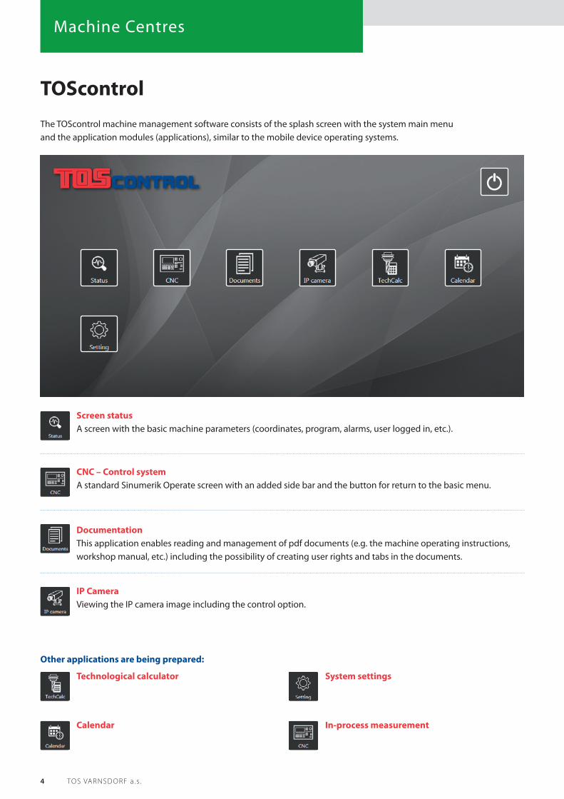
TOScontrol
Screen status A screen with the basic machine parameters (coordinates, program, alarms, user logged in, etc.).
CNC – Control system A standard Sinumerik Operate screen with an added side bar and the button for return to the basic menu.
Documentation This application enables reading and management of pdf documents (e.g. the machine operating instructions, workshop manual, etc.) including the possibility of creating user rights and tabs in the documents.
IP Camera Viewing the IP camera image including the control option.
Other applications are being prepared:
Technological calculator
Calendar
System settings
In-process measurement
The TOScontrol machine management software consists of the splash screen with the system main menu and the application modules (applications), similar to the mobile device operating systems.
5WHT 110 (C )
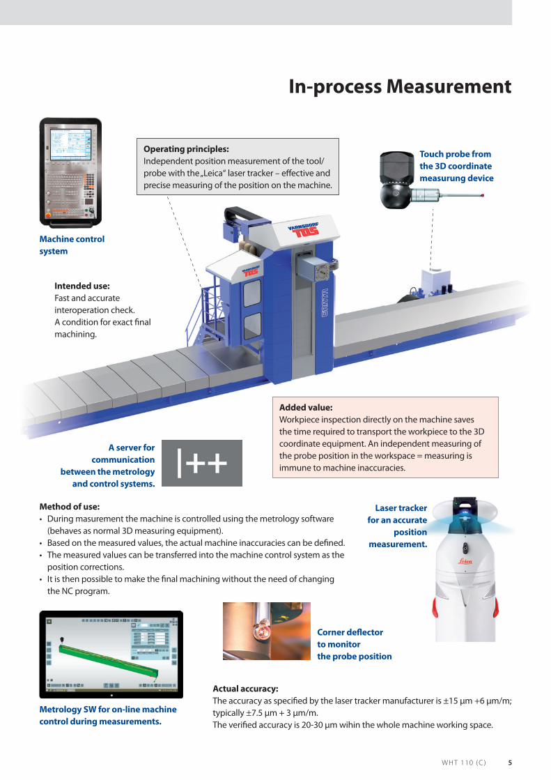
In-process Measurement
Operating principles:Independent position measurement of the tool/probe with the „Leica“ laser tracker – eff ective and precise measuring of the position on the machine.
Method of use:• During masurement the machine is controlled using the metrology software
(behaves as normal 3D measuring equipment).• Based on the measured values, the actual machine inaccuracies can be defi ned.• The measured values can be transferred into the machine control system as the
position corrections.• It is then possible to make the fi nal machining without the need of changing
the NC program.
Machine control system
Actual accuracy:The accuracy as specifi ed by the laser tracker manufacturer is ±15 μm +6 μm/m; typically ±7.5 μm + 3 μm/m.The verifi ed accuracy is 20-30 μm wihin the whole machine working space.
Intended use:Fast and accurate interoperation check. A condition for exact fi nal machining.
Added value:Workpiece inspection directly on the machine saves the time required to transport the workpiece to the 3D coordinate equipment. An independent measuring of the probe position in the workspace = measuring is immune to machine inaccuracies.
A server for communication
between the metrology and control systems.
Laser tracker for an accurate
position measurement.
Metrology SW for on-line machine control during measurements.
Touch probe from the 3D coordinate measurung device
Corner defl ector to monitor the probe position

Machine Centres
6 TOS VARNSDORF a . s .
Machhine frameBasic heavy machine parts (tables, palettes, longitudinal and transverse
beds) are casted from grey iron. The machine column is designed as a twin-shell casting also made of grey iron with an optimised
structure.
Machhine frameBasic heavy m
beds) area tw
CounterbalancingThe headstock weight is compensated hydromechanically (using a hydraulic cylinder) with use of a standalone hydraulic power unit.
WHT 110 (C)

7WHT 110 (C )
Central headstockThe WHT 110 machine is equipped with a central core headstock. This solution is optimum in respect to a uniform thermal and mechanical loading of the machine frame. The spindle is driven from a standardised gear case connected to the main motor. Two mechanical spindle speed ranges are shifted electromechanically. The travelling spindle is sliding in the hollow spindle.
X, Y, Z and W axis drivesThe linear axes are driven by standalone actuators with embedded belt gears and ball screws with a large pitch. The X and Z axes are
driven from the ball screws with rotating ball nuts. The Y and W axis are driven from the rotating ball screws.
Travelling group guidesAll the linear trvelling machine groups in the X, Y and Z axes are guided
in the pre-loaded compact rolling linear guideways. The travelling spindle is sliding in the hollow spindle. The table is supported
on a large radial-thrust cylindrical roller bearing with high capacity and rigidity.
Automatic change of technological palettesConceptually, the palette change equipment is based on the automatic change of the technological palettes between the stationary stowage stations and the palette clamping base on the machine. The palettes are handled using a rotary palette manipulator.
X, Y, Z aThe linebelt ge
drivena
TravellingAll the l
in th
WHT 110 (C)

Machine Centres
8 TOS VARNSDORF a . s .
TECHNICAL PARAMETERS – BASIC MACHINE PARAMETERS
Machine type WHT 110 S WHT 110 L WHT 110 SC WHT 110 LC
Headstock
Working spindle diameter mm 112
Spindle taper ISO 50
Working spindle speed range 1 rpm 10 – 4 000 10 – 6 000
Main motor nominal power S1 kW 28 31
Nominal torque on the spidle S1 Nm 1 200 1 375
Spindle stroke W mm 650
Column
Headstock vertical travel, Y mm 1 250 1 600 1 250 1 600
Longitudinal column adjustment Z mm 1 500 2 500 1 500 2 500
Rotary table
Transverse table travel, X mm 1 500 2 500 1 500 2 500
Max. workpiece weight kg 6 000
Table clamping area dimesions mm 1 250 x 1 250 1 250 x 1 600 1 250 x 1 250 1 250 x 1 600
Feeds
Feed and rapid traverse ranges – X, Y, Z mm/min 25 000 40 000
Feed and rapid traverse ranges – W mm/min 20 000
Feed and rapid traverse ranges – B 1/min 3
Basic machine equipment:
– Chip conveyor • •
– Machine operator covering • •
– X-axis covering • •
– Modifi cation for the manual change of the manually adjusted miling heads •
– Remote diagnostics • •
– Complete machine enclosure (including the machine operator covering) •
– Automatic tool change AVN 40 •
– Modifi cation for the automatic change of the milling heads (UPPT) •
– CHZ tool cooling (via the external nozzles) •
Basic horizotal table type machines or centres are available in two versions – S (small) and L (large). Each version has its pre-defi ned parameters (see the table) and equipment. It is possible to only select from the range of options (e.g. milling heads, face plates, etc.).

9WHT 110 (C )
OPTIONAL MACHINE VERSIONS
Machine type WHT 110 WHT 110 C
Headstock
Working spindle diameter mm 112
Spindle taper ISO 50
Working spindle speed range 1 rpm 10 – 4 000 10 – 4 000 10 – 6 000
Main motor nominal power S1 kW 28 28 31
Nominal torque on the spidle S1 Nm 1 200 1 200 1 375
Primary spindle travel W mm 650
Column
Headstock vertical travel, Y mm 1 250, 1 600, 2 000*
Longitudinal column adjustment Z mm 1 500, 2 000, 2 500
Rotary table
Transverse table travel, X mm 1 500, 2 000, 2 500, 3 000
Max. workpiece weight kg 6 000
Table clamping area dimesions mm 1 250 x 1 250, 1 250 x 1 600
Turning table
Traverse table travel, X mm 1 500, 2 000, 2 500, 3 000
Max. workpiece weight (max. palette load) kg 6 000 (4 000)
Table clamping area dimensions mm Ø 1 600
Automatic palette change
Transverse table travel, X mm 1 500, 2 000, 2 500, 3 000
Max. palette load kg 4 000
Palette clamping area mm 1 250 x 1 250, 1 250 x 1 600
Max. number of palettes ks 2 to 4
Automatic tool change
Number of pockets – circular type magazine ks 20
Number of pockets – chain type magazine ks 40, 60, 80
Number of pockets – rack type magazine ks 100+
Max. tool diameter
– with the magazine fully occupied mm 125
– with the free adjacent positions mm 300
Max. tool length mm 500
Tool change time s 10
* Only for WHT 110

Machine Centres
10 TOS VARNSDORF a . s .
Machine covering
Covering basic version: the bed, column and operator‘s place covers
Protective covering of the workspace: the bed, colum and operator‘s position covers and workspace protective covering that includes a removable sheet metal cab
„C“ cover: the beds, the column, the machine operator‘s station, and the workspace covering
along the X and Z axes
Horizontal machine tool
A complete covering of the machining centre. In addition to the covering, a chip washing option or the workspace exhaustion can be specifi ed.
Horizontal machining centre
Optional version
Machine covers with the automatic tool change: bed, column, operator‘s place and automatic tool change
covers

11WHT 110 (C )
Technology examples

Accessories
12 TOS VARNSDORF a . s .
Milling heads and face plates
HUI 50HUI 50, a milling head, is automatically indexed in both planes with an incerement of 2.5° and ensures a higher effi ciency of rotating the head spindle against the machine system of coordinates.
• Number of axes: 2• Rotation speed
(rpm)): 3 000• Power (kW): 32• Torque (Nm): 1 000• Positioning: index 2,5°• Weight (kg): 440
02,5°
HUR 50HUR 50, a universal milling head with manual positioning, consists of three compact attached basic parts that may be rotated one against another to achieve the required position of the primary spindle. The angle can be set with an increment of 0.1° with use of the circumferential vernier-fi tted scales. The setting dowels are used to position the head parts in one of the eight basic positions (4x90° in the vertical split plane, 2x180° in the inclined split plane).
• Number of axes: 2• Rotation speed
(rpm): 3 000• Power (kW): 20• Torque (Nm): 1 000• Positioning: manual• Weight (kg): 330
HPR 50HPR 50, a rectangular manual head, consists of two compact attached basic parts that may be rotated one against another to achieve the required position of the primary spindle.
• Number of axes: 1• Rotation speed
(rpm): 3 000• Power (kW): 25• Torque (Nm): 1 200• Positioning: manual• Weight (kg): 200
HOIL 50HOIL 50, an orthogonal, automatically indexed light head uses the same basic design as the HOI 50 head.
• Number of axes: 2• Rotation speed
(rpm): 3 500• Power (kW): 25• Torque (Nm): 1 000• Positioning: index 1°• Weight (kg): 450
2
00x 1°
D‘Andrea Face plate• Max. boring diameter: 1 000/1 250/ 1 400 mm• Plate size: 500 /600 /800 mm• Feed range: 160 /200 /250 mm• Boring accuracy: 0,01 mm• Positioning: automatic

Accessories
13WHT 110 (C )
Automatic Tool Change (ATC)It consists of a chain-type or a rack-type magazine, a manipulator on the column or on the rack, and the manipulator with the swivelling two-arm grabber. The tools are searched using the coded pockets in the magazine.
The device allows automatic changing of the tools in the milling heads both horizontally and vertically.
The number of pockets can be selected according to the customer‘s needs.
Chain-type magazine Rack-type magazine
Accessories
14 TOS VARNSDORF a . s .
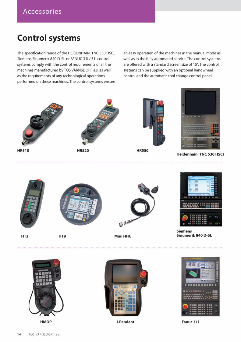
Control systemsThe specifi cation range of the HEIDENHAIN iTNC 530 HSCI, Siemens Sinumerik 840 D-SL or FANUC 31i / 31i control systems comply with the control requirements of all the machines manufactured by TOS VARNSDORF a.s. as well as the requirements of any technological operations performed on these machines. The control systems ensure
an easy operation of the machines in the manual mode as well as in the fully automated service. The control systems are off ered with a standard screen size of 15“. The control systems can be supplied with an optional handwheel control and the automatic tool change control panel.
HT2 HT8 Mini HHU
HMOP I-Pendant
HR520 HR550HR510Heidenhain iTNC 530 HSCI
Siemens Sinumerik 840 D-SL
Fanuc 31i

Accessories
15WHT 110 (C )
Other accessories and servicesPICK UP systemA special accessory support rack is used for stacking the special technological accessories and its changing with use of the PICK-UP system. Its design (the number of storage positions, way of stacking, etc.) is based on the caustomer‘s individual needs.
For table type machines, it is possible to choose one of two column cover designs: with the swivelling door or the roll-up door. It is also possible to specify an optional column that is attached and fi xed to the rotary table, or a column that is attached to the swivelling arms on the rotary table, or a column mounted on the concrete fl oor at the machine; this solution may also be applied to the WHT 110 C machining centres.
Clamping devicesClamping devices are used for horizontal boring mills as a special technological accessory. They are used for clamping the workpieces.
Clamping blocks: UK 500 – UK 3 000

Accessories
16 TOS VARNSDORF a . s .
Tool coolingTwo tool cooling methods can be applied to the machines produced in TOS VARNSDORF: tool cooling with use of adjustable nozzles (CHZ) or internal axial tool cooling (CHOV). The axial cooling can also be used with the milling head attached.
ProbesVarious probes can be selected for each control system.
Chip conveyorThe chip conveyor is provided with each version of the machine as a standard part of delivery.

Components
17WHT 110 (C )
Other componentsLubricating systemAn automatic total loss lubrication system with a central lubricating unit ensures lubrication of the travelling group sliding guideways and the ball nuts in the feed drives. The spindle drive gear lubrication in the headstock is ensured by an automatic oil circulating lubrication system.
Power suppliesThe electrical equipment is primarily located in the four-piece electrical cabinet. It includes the control system basic module as well as the feed drive control and the spindle drive control with all the supply, switching and circuit breaking devices. The electrical equipment consists of the products of renowned manufacturers.
Linear guidewaysThis concept ensures a high accuracy and rigidity of the guideways as well as a low friction coeffi cient. It also allows using high travel speeds and ensures a long lifetime. Individual linear guideways are located at the positions with the highest load and force transmission. Due to the profi led rail design the carriage can absorb the forces both in vertical and horizontal directions. Machines equipped with linear guides can be fi tted with a direct measuring system integrated into the linear guide.
Hydraulic unitThe pressure oil for lubrication of the guideways is supplied from the lubrication unit located together with a hydraulic unit in a separate cabinet.

Human Resources:Tel.: +420 412 351 123E-mail: [email protected]
TOS VARNSDORF a.s.Říční 1774407 47 VarnsdorfCzech RepublicTel.: +420 412 351 203Fax: +420 412 351 269E-mail: [email protected]
Marketing and Advertising:Tel.: +420 412 351 216E-mail: [email protected]
Service:Tel.: +420 412 351 230E-mail: [email protected]
Cooperation:Tel.: +420 412 351 406E-mail: [email protected]
WORLDWIDE
02-2
017
The data and parameters mentioned in this catalogue are not binding. The manufacturer reserves the right to change them without notifi cation.