your motor speed control solutions provider - brushless … · your motor speed control solutions...
TRANSCRIPT

Your Motor Speed Control Solutions Provider
RoHS CompliantRoHS Compliant
P.O. Box 10, 5000 W. 106th Street, Zionsville, Indiana 46077Phone: (317) 873-5211 FAX: (317) 873-1105
www.dartcontrols.comISO 9001:2000 REGISTERED RoHS Compliant
All information contained in this catalog is intended to be correct, however information and data in this catalog are subject to change without notice. Dart Controls, Inc. (DCI) makes no warranty of any kind with regard to this information or data. Further, DCI is not responsible for any omissions or errors or consequential damage caused by the user of the product. DCI reserves the right to make manufacturing changes which may not be included in this catalog.
Since 1963, Dart Controls hasbeen designing and manufacturingvariable speed drives, controls,and accessor ies for electr ic motors in our Zionsville, Indiana
facility.Our Mission is to be
the company you want to do business with.We pursue this goal bycontinuously seeking waysto improve our quality, efficiency, and services,while maintaining our
commitment to our customers, e m p l o y e e s , sha r eho l d e r s and suppliers.
A l w a y s seek ing ways to provide total value through innovation Dart recently expanded by adding a new Engineering andR&D facility.
Over the last decade Darthas al so implemented theconcepts of leanmanufacturing.Through the use of lean tool ssuch as StandardWork, Kanban, K a i z en , J I T,Visual Control Sy s t ems andPoka-Yoke (error proofing) we continue to improve and refine our processes and practices.
The benefit to our customersis a reduction to their inventorymade possible by our flexible support systemsallowing us toreliably deliver
any size order with an extremely fast turnaround.DART DELIVERS! PUT US TO THE TEST
Dart Delivers What You Want…When You Need It!
2
TABLE OF CONTENTS PAGE
SCR DC SPEED CONTROLS (1/50–3 Horsepower) 4–12 500 Series 250 Series 130 Series 125 Series 15 Series
VOLTAGE SIGNAL ISOLATOR 13 VSI Series
PWM DC SPEED CONTROLS 14–15 DPW Series
DIGITAL DC SPEED CONTROLS (1/50–2 Horsepower) 16–21 MD Series MD plus Series MD II Series
DIGITAL & ANALOG CONTROL SYSTEMS (open/closed loop) 22–27 Accu-Set Series Accu-Set II Series DP4 Series MSC38A Series
FIELD PROGRAMMABLE DIGITAL TACHOMETERS 28–29 DM8000 Series
DC BRUSHLESS MOTOR SPEED CONTROLS 30–31 700/Commutrol Series
BATTERY OPERATED MOTOR SPEED CONTROLS 32–33 65 Series
VARIABLE AC VOLTAGE SUPPLIES 34 55AC Series and AC03 Series
SPEED SENSORS 35–38 PU-E Pick-up Series Optical Pick-up Series CF Pick-up Series MPU-A Pick-up Series
DEFINITION OF TERMS 39
STANDARD STOCK DC MOTORS (1/4–2.0 Horsepower) 40–41 Stock DC Motors
APPLICATION HIGHLIGHTS 42–47
3www.dartcontrols.com
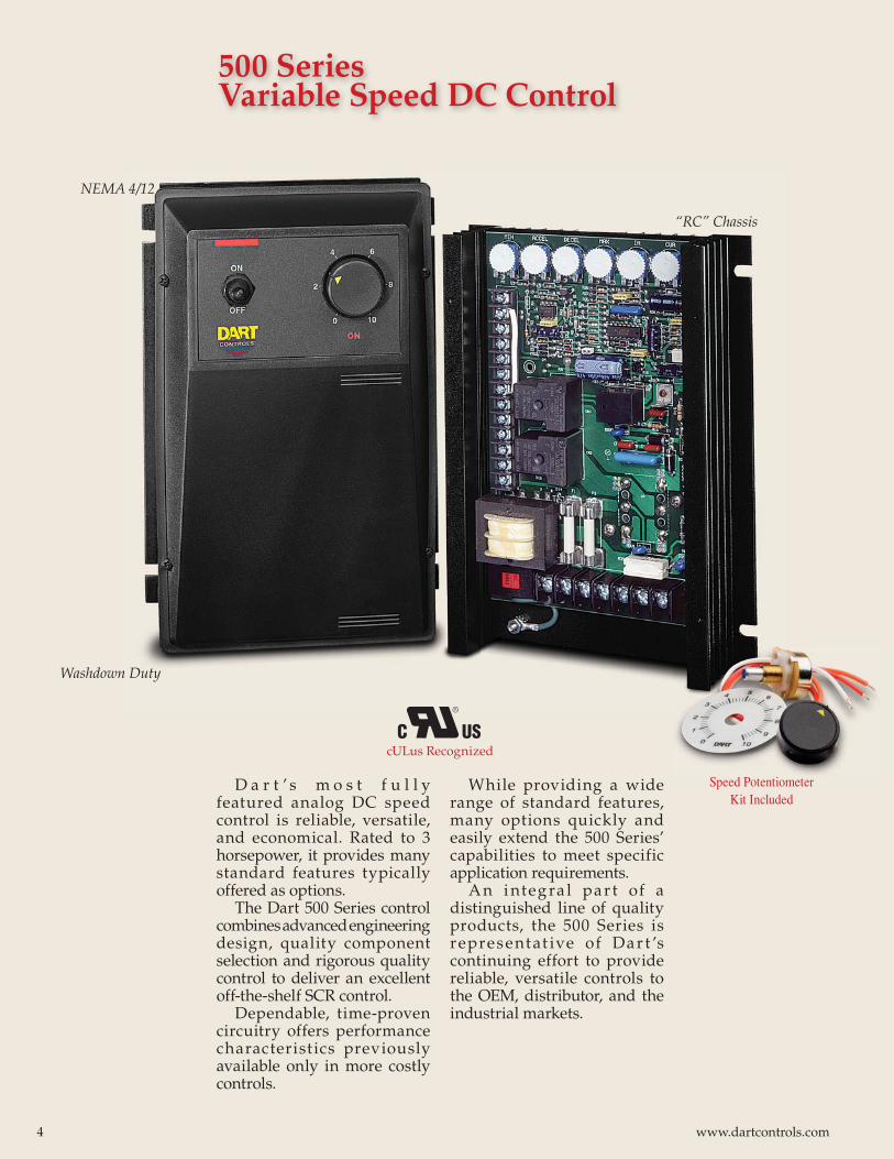
D a r t ’ s m o s t f u l l y featured analog DC speed control is reliable, versatile, and economical. Rated to 3 horsepower, it provides many standard features typically offered as options.
The Dart 500 Series control combines advanced engineering design, quality component selection and rigorous quality control to deliver an excellent off-the-shelf SCR control.
Dependable, time-proven circuitry offers performance characteristics previously available only in more costly controls.
While providing a wide range of standard features, many options quickly and easily extend the 500 Series’ capabilities to meet specific application requirements.
A n i nteg ra l par t of a distinguished line of quality products, the 500 Series is representat ive of Dar t ’s continuing effort to provide reliable, versatile controls to the OEM, distributor, and the industrial markets.
Washdown Duty
“RC” Chassis
NEMA 4/12
500 Series Variable Speed DC Control
Speed Potentiometer Kit Included
cULus Recognized
4 www.dartcontrols.com
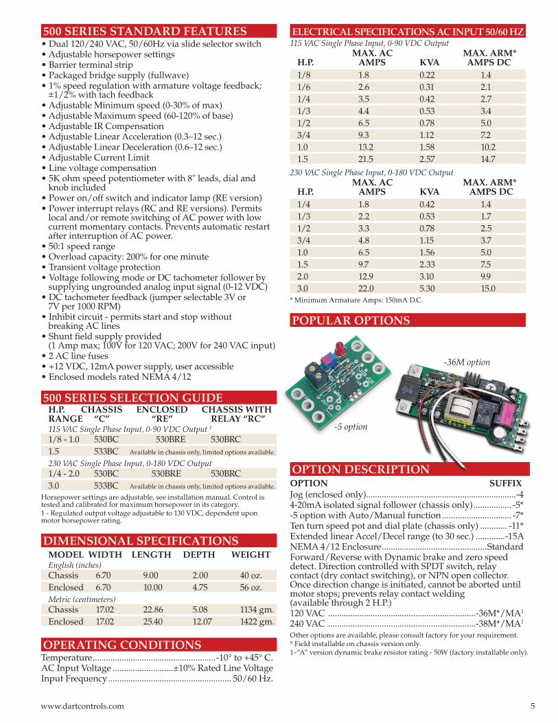
-5 option
-36M option
500 SERIES STANDARD FEATURES• Dual 120/240 VAC, 50/60Hz via slide selector switch• Adjustable horsepower settings• Barrier terminal strip• Packaged bridge supply (fullwave)• 1% speed regulation with armature voltage feedback;
±1/2% with tach feedback• Adjustable Minimum speed (0-30% of max)• Adjustable Maximum speed (60-120% of base)• Adjustable IR Compensation• Adjustable Linear Acceleration (0.3–12 sec.)• Adjustable Linear Deceleration (0.6–12 sec.)• Adjustable Current Limit• Line voltage compensation• 5K ohm speed potentiometer with 8" leads, dial and knob included• Power on/off switch and indicator lamp (RE version)• Power interrupt relays (RC and RE versions). Permits local and/or remote switching of AC power with low current momentary contacts. Prevents automatic restart after interruption of AC power.• 50:1 speed range• Overload capacity: 200% for one minute• Transient voltage protection• Voltage following mode or DC tachometer follower by supplying ungrounded analog input signal (0-12 VDC)• DC tachometer feedback (jumper selectable 3V or 7V per 1000 RPM)• Inhibit circuit - permits start and stop without breaking AC lines• Shunt fi eld supply provided (1 Amp max; 100V for 120 VAC; 200V for 240 VAC input)• 2 AC line fuses• +12 VDC, 12mA power supply, user accessible• Enclosed models rated NEMA 4/12
500 SERIES SELECTION GUIDE H.P. CHASSIS ENCLOSED CHASSIS WITH RANGE “C” “RE” RELAY “RC” 115 VAC Single Phase Input, 0-90 VDC Output 1
1/8 - 1.0 530BC 530BRE 530BRC 1.5 533BC Available in chassis only, limited options available.
230 VAC Single Phase Input, 0-180 VDC Output 1/4 - 2.0 530BC 530BRE 530BRC 3.0 533BC Available in chassis only, limited options available.
Horsepower settings are adjustable, see installation manual. Control is tested and calibrated for maximum horsepower in its category.1 - Regulated output voltage adjustable to 130 VDC, dependent upon motor horsepower rating.
DIMENSIONAL SPECIFICATIONS MODEL WIDTH LENGTH DEPTH WEIGHT English (inches) Chassis 6.70 9.00 2.00 40 oz. Enclosed 6.70 10.00 4.75 56 oz.
Metric (centimeters) Chassis 17.02 22.86 5.08 1134 gm.
Enclosed 17.02 25.40 12.07 1422 gm.
OPERATING CONDITIONSTemperature .......................................................-10° to +45° C.AC Input Voltage ...........................±10% Rated Line VoltageInput Frequency ....................................................... 50/60 Hz.
ELECTRICAL SPECIFICATIONS AC INPUT 50/60 HZ 115 VAC Single Phase Input, 0-90 VDC Output MAX. AC MAX. ARM* H.P. AMPS KVA AMPS DC 1/8 1.8 0.22 1.4 1/6 2.6 0.31 2.1 1/4 3.5 0.42 2.7 1/3 4.4 0.53 3.4 1/2 6.5 0.78 5.0 3/4 9.3 1.12 7.2 1.0 13.2 1.58 10.2 1.5 21.5 2.57 14.7
230 VAC Single Phase Input, 0-180 VDC Output MAX. AC MAX. ARM* H.P. AMPS KVA AMPS DC 1/4 1.8 0.42 1.4 1/3 2.2 0.53 1.7 1/2 3.3 0.78 2.5 3/4 4.8 1.15 3.7 1.0 6.5 1.56 5.0 1.5 9.7 2.33 7.5 2.0 12.9 3.10 9.9 3.0 22.0 5.30 15.0
* Minimum Armature Amps: 150mA D.C.
POPULAR OPTIONS
OPTION DESCRIPTIONOPTION SUFFIXJog (enclosed only)...................................................................-44-20mA isolated signal follower (chassis only) ................. -5*-5 option with Auto/Manual function ............................... -7*Ten turn speed pot and dial plate (chassis only) ............ -11*Extended linear Accel/Decel range (to 30 sec.) .............-15ANEMA 4/12 Enclosure ...............................................StandardForward/Reverse with Dynamic brake and zero speeddetect. Direction controlled with SPDT switch, relay contact (dry contact switching), or NPN open collector. Once direction change is initiated, cannot be aborted until motor stops; prevents relay contact welding (available through 2 H.P.)120 VAC ..................................................................-36M*/MA1
240 VAC ..................................................................-38M*/MA1
Other options are available, please consult factory for your requirement.* Field installable on chassis version only.1–“A” version dynamic brake resistor rating - 50W (factory installable only).
5www.dartcontrols.com
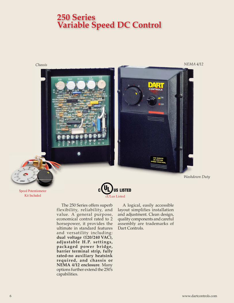
The 250 Series offers superb f lexibility, reliability, and value. A general purpose, economical control rated to 2 horsepower, it provides the ultimate in standard features and versatility including: dual voltage (120/240 VAC), adjustable H.P. set t ings, packaged power br idge, barrier terminal strip, fully rated-no auxiliary heatsink required, and chassis or NEMA 4/12 enclosure. Many options further extend the 250’s capabilities.
A logical, easily accessible layout simplifies installation and adjustment. Clean design, quality components and careful assembly are trademarks of Dart Controls.
250 Series Variable Speed DC Control
Chassis
Washdown Duty
NEMA 4/12
cULus Listed
Speed Potentiometer Kit Included
6 www.dartcontrols.com
ELECTRICAL SPECIFICATIONS AC INPUT 50/60 HZ120 VAC Single Phase Input, 0-90 VDC Output MAX. AC MAX. ARM* H.P. AMPS KVA AMPS DC 1/50 0.5 0.06 0.4 1/20 1.0 0.12 0.8 1/8 2.0 0.24 1.6 1/4 3.5 0.42 2.7 1/3 4.4 0.53 3.4 1/2 6.5 0.78 5.0 3/4 9.3 1.12 7.2 1 13.2 1.58 10.2
240 VAC Single Phase Input, 0-180 VDC Output MAX. AC MAX. ARM* H.P. AMPS KVA AMPS DC 1/4 1.8 0.42 1.4 1/3 2.2 0.53 1.7 1/2 3.3 0.78 2.5 3/4 4.8 1.15 3.7 1 6.5 1.56 5.0 1 1/2 9.7 2.33 7.5 2 12.9 3.10 9.9For dual voltage 250 series, use table for the input voltage you are using.* Minimum Armature Amps: 150mA D.C.
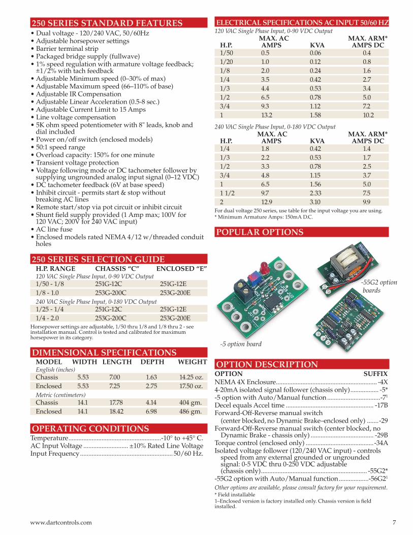
POPULAR OPTIONS
250 SERIES STANDARD FEATURES• Dual voltage - 120/240 VAC, 50/60Hz• Adjustable horsepower settings• Barrier terminal strip• Packaged bridge supply (fullwave)• 1% speed regulation with armature voltage feedback; ±1/2% with tach feedback• Adjustable Minimum speed (0–30% of max)• Adjustable Maximum speed (66–110% of base)• Adjustable IR Compensation• Adjustable Linear Acceleration (0.5-8 sec.)• Adjustable Current Limit to 15 Amps• Line voltage compensation• 5K ohm speed potentiometer with 8" leads, knob and dial included• Power on/off switch (enclosed models)• 50:1 speed range• Overload capacity: 150% for one minute• Transient voltage protection• Voltage following mode or DC tachometer follower by supplying ungrounded analog input signal (0–12 VDC)• DC tachometer feedback (6V at base speed)• Inhibit circuit - permits start & stop without breaking AC lines• Remote start/stop via pot circuit or inhibit circuit• Shunt fi eld supply provided (1 Amp max; 100V for 120 VAC; 200V for 240 VAC input)• AC line fuse• Enclosed models rated NEMA 4/12 w/threaded conduit holes
250 SERIES SELECTION GUIDE H.P. RANGE CHASSIS “C” ENCLOSED “E” 120 VAC Single Phase Input, 0-90 VDC Output 1/50 - 1/8 251G-12C 251G-12E 1/8 - 1.0 253G-200C 253G-200E
240 VAC Single Phase Input, 0-180 VDC Output 1/25 - 1/4 251G-12C 251G-12E 1/4 - 2.0 253G-200C 253G-200E
Horsepower settings are adjustable, 1/50 thru 1/8 and 1/8 thru 2 - see installation manual. Control is tested and calibrated for maximum horsepower in its category.
DIMENSIONAL SPECIFICATIONS MODEL WIDTH LENGTH DEPTH WEIGHT English (inches) Chassis 5.53 7.00 1.63 14.25 oz. Enclosed 5.53 7.25 2.75 17.50 oz.
Metric (centimeters) Chassis 14.1 17.78 4.14 404 gm. Enclosed 14.1 18.42 6.98 486 gm.
OPERATING CONDITIONSTemperature ........................................................-10° to +45° C.AC Input Voltage ........................... ±10% Rated Line VoltageInput Frequency ........................................................ 50/60 Hz.
OPTION DESCRIPTIONOPTION SUFFIXNEMA 4X Enclosure ............................................................. -4X4-20mA isolated signal follower (chassis only) ................. -5* -5 option with Auto/Manual function ................................-71
Decel equals Accel time ..................................................... -17BForward-Off-Reverse manual switch (center blocked, no Dynamic Brake–enclosed only) .......-29Forward-Off-Reverse manual switch (center blocked, no Dynamic Brake - chassis only) ...................................... -29BTorque control (enclosed only) .........................................-34AIsolated voltage follower (120/240 VAC input) - controls speed from any external grounded or ungrounded signal: 0-5 VDC thru 0-250 VDC adjustable (chassis only) ................................................................ -55G2*-55G2 option with Auto/Manual function ..................-56G21
Other options are available, please consult factory for your requirement.* Field installable1–Enclosed version is factory installed only. Chassis version is fi eld installed.
-5 option board
-55G2 option boards
7www.dartcontrols.com
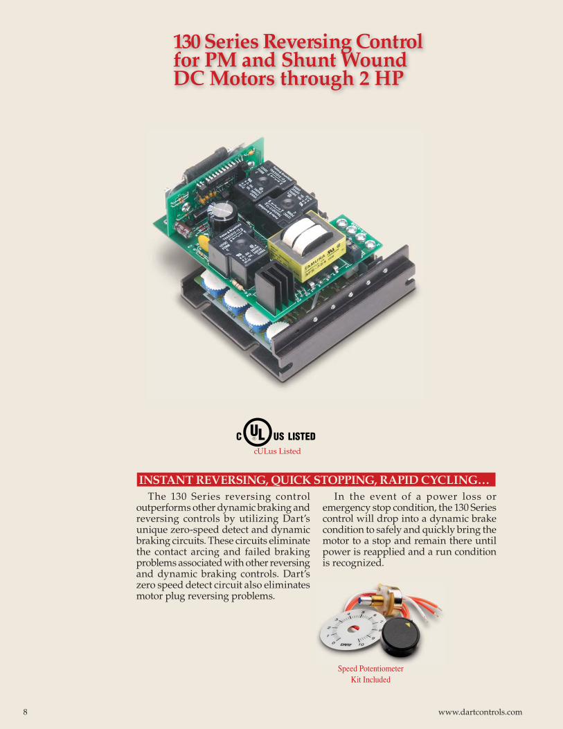
The 130 Series reversing control outperforms other dynamic braking and reversing controls by utilizing Dart’s unique zero-speed detect and dynamic braking circuits. These circuits eliminate the contact arcing and failed braking problems associated with other reversing and dynamic braking controls. Dart’s zero speed detect circuit also eliminates motor plug reversing problems.
In the event of a power loss or emergency stop condition, the 130 Series control will drop into a dynamic brake condition to safely and quickly bring the motor to a stop and remain there until power is reapplied and a run condition is recognized.
INSTANT REVERSING, QUICK STOPPING, RAPID CYCLING…
130 Series Reversing Control for PM and Shunt Wound DC Motors through 2 HP
cULus Listed
Speed Potentiometer Kit Included
8 www.dartcontrols.com
4.063
130 SERIES STANDARD FEATURES• Adjustable horsepower settings• Barrier terminal blocks• Full wave bridge supply• Adjustable Min speed (0-30% of max)• Adjustable Max speed (60-100% of base)• Adjustable IR compensation• Adjustable current limit• Fixed accel (0.5 sec); or 6 sec “soft start” w/(-K) option• Line voltage compensation• 5K speed pot with 8" leads, dial and knob included• 50:1 speed range• Overload capacity: 200% for one minute• Transient voltage protection• Shunt fi eld supply provided (1 Amp max; 100V for 120 VAC input or 200V for 240 VAC input)• Onboard dynamic brake resistor• Automatic dynamic braking on power loss• 1% speed regulation with armature voltage feedback
130 SERIES MODEL NUMBERS AND RATINGS INPUT OUTPUT CYCLE MODEL VOLTAGE HP RANGE AMPS DC RATE130LC12 120 VAC 1/15-1/8 1.2 3 C/MIN130LC100 120 VAC 1/8-1/2 5.5* 3 C/MIN130HC12 120 VAC 1/15-1/8 1.2 UP TO 30 C/MIN130HC100 120 VAC 1/8-1.0 10.0 UP TO 30 C/MIN132LC25 240 VAC 1/25-1/4 1.2 3 C/MIN132LC200 240 VAC 1/8-1.0 5.5** 3 C/MIN132HC25 240 VAC 1/25-1/4 1.2 UP TO 30 C/MIN132HC200 240 VAC 1/4-2.0 10.0 UP TO 30 C/MIN
* Up to 10 amps continuous output current at 1 Hp 90VDC with suitable external heat sink. ** Up to 10 amps continuous output current at 2 Hp 180VDC with suitable external heat sink.
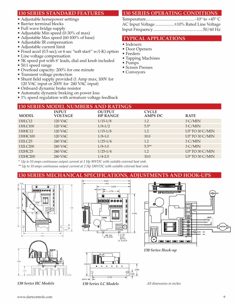
130 SERIES MECHANICAL SPECIFICATIONS, ADJUSTMENTS AND HOOK-UPS
130 Series Hook-up
130 Series LC Models
130 SERIES OPERATING CONDITIONSTemperature ............................................... -10° to +45° CAC Input Voltage ..................±10% Rated Line VoltageInput Frequency ................................................50/60 Hz
TYPICAL APPLICATIONS• Indexers• Door Openers• Feeders• Tapping Machines• Pumps• Screen Presses• Conveyors
All dimensions in inches130 Series HC Models
9www.dartcontrols.com
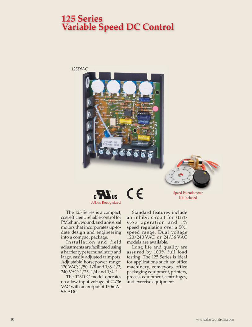
The 125 Series is a compact, cost effi cient, reliable control for PM, shunt wound, and universal motors that incorporates up-to-date design and engineering into a compact package.
I n st a l lat ion a nd f ie ld adjustments are facilitated using a barrier type terminal strip and large, easily adjusted trimpots. Adjustable horsepower range: 120 VAC; 1/50–1/8 and 1/8–1/2; 240 VAC; 1/25–1/4 and 1/4–1.
The 123D-C model operates on a low input voltage of 24/36 VAC with an output of 150mA–5.5 ADC
Standard features include an inhibit circuit for start-s top op erat io n a nd 1% speed regulation over a 50:1 speed range. Dual voltage 120/240 VAC or 24/36 VAC models are available.
Long life and quality are assured by 100% full load testing. The 125 Series is ideal for applications such as: offi ce machinery, conveyors, office packaging equipment, printers, process equipment, centrifuges, and exercise equipment.
125 Series Variable Speed DC Control
125DV-C
Speed Potentiometer Kit Included
cULus Recognized
10 www.dartcontrols.com
-2A option
-5 option
125 SERIES STANDARD FEATURES• Dual Voltage 120/240 VAC or 24/36 VAC, 50/60Hz• Adjustable horsepower settings• Barrier terminal strip• Full wave bridge supply• 1% speed regulation with armature voltage feedback; ±1/2% with tach feedback• Adjustable Minimum speed (0–30% of max)• Adjustable Maximum speed (60–110% of base)• Adjustable IR Compensation• Adjustable Current Limit• Fixed Acceleration (0.5 sec.)• Line voltage compensation• 5K ohm speed potentiometer with 8" leads, dial & knob included• 50:1 speed range• Overload capacity: 200% for one minute• Transient voltage protection• Voltage following mode or DC tachometer follower by supplying ungrounded analog input signal (0–12 VDC)• DC tachometer feedback (6V at base speed)• Inhibit circuit–permits start & stop without breaking AC lines• Shunt fi eld supply provided (1 Amp max; 100V for 120 VAC; 200V for 240 VAC input) 125 SERIES SELECTION GUIDE H.P. RANGE MODEL INPUT OUTPUT
150mA - 5.5ADC 123D-C 24/36 VAC 0-20/30 VDC1/50 - 1/8 120 VAC 0-90 VDC1/25 - 1/4 240 VAC 0-180 VDC1/8 - 1/2* 120 VAC 0-90 VDC1/4 - 1.0* 240 VAC 0-180 VDC
* With suitable external heatsink. UL rating for output amps can be increased from 5.5 amps DC to 10.0 amps DC.Horsepower settings are adjustable - see installation manual. Control is tested and calibrated for maximum horsepower in its category.
OPERATING CONDITIONSTemperature ........................................................-10° to +45° C.AC Input Voltage ............................±10% Rated Line VoltageInput Frequency ........................................................ 50/60 Hz.
ELECTRICAL SPECIFICATIONS AC INPUT 50/60 HZ120 VAC Single Phase Input, 0-90 VDC Output MAX. AC MAX. ARM*H.P. AMPS KVA AMPS DC1/50 0.5 0.06 0.41/20 1.0 0.12 0.81/8 2.0 0.24 1.61/4 3.5 0.42 2.71/3 4.4 0.53 3.41/2 6.5 0.78 5.0
240 VAC Single Phase Input, 0-180 VDC Output MAX. AC MAX. ARM*H.P. AMPS KVA AMPS DC1/4 1.8 0.42 1.41/3 2.2 0.53 1.71/2 3.3 0.78 2.53/4 4.8 1.15 3.71 6.5 1.56 5.0
* Minimum Armature Amps: 150mA DC
DIMENSIONAL SPECIFICATIONS MODEL WIDTH HEIGHT DEPTH WEIGHT English (inches) Chassis 3.63 4.25 1.30 8 oz. Metric (centimeters)Chassis 9.20 10.80 3.30 227 gm.
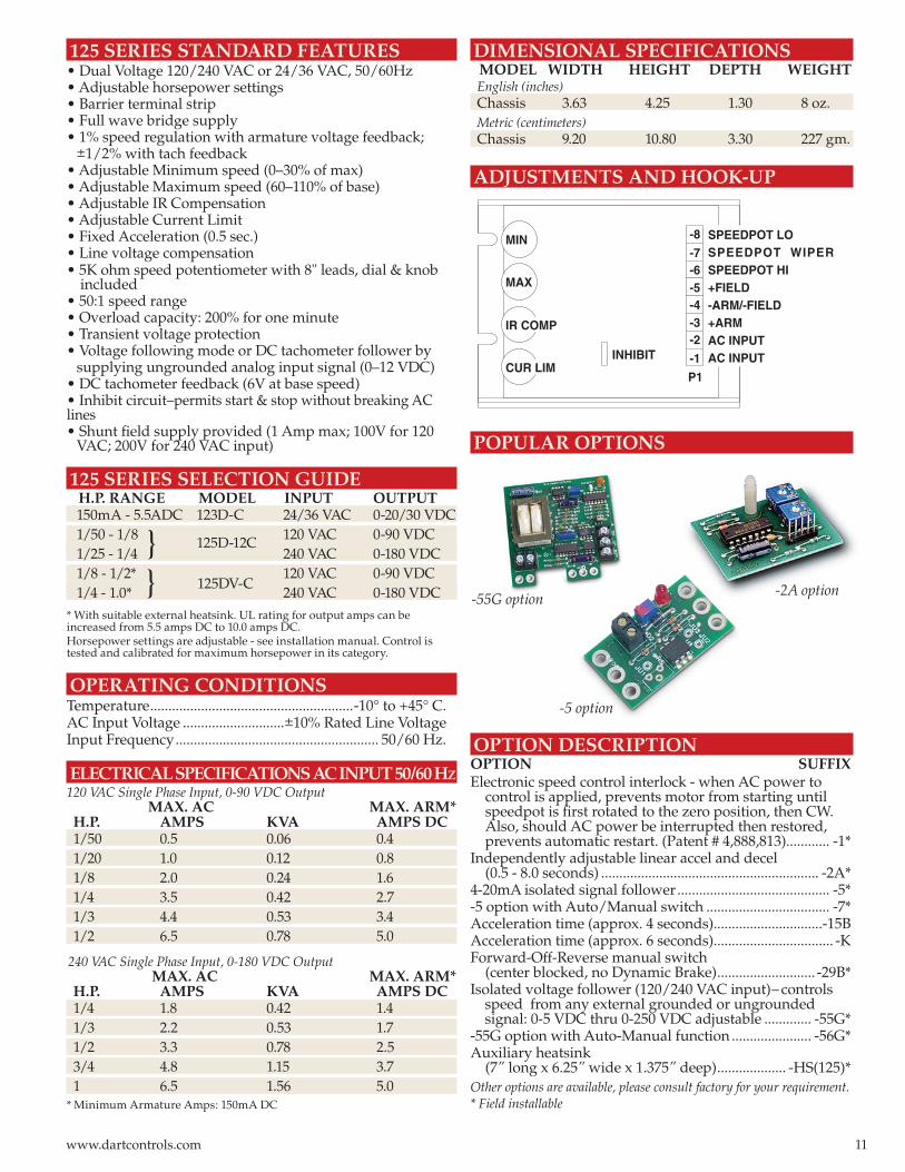
ADJUSTMENTS AND HOOK-UP
POPULAR OPTIONS
OPTION DESCRIPTIONOPTION SUFFIXElectronic speed control interlock - when AC power to control is applied, prevents motor from starting until speedpot is fi rst rotated to the zero position, then CW. Also, should AC power be interrupted then restored, prevents automatic restart. (Patent # 4,888,813)............ -1*Independently adjustable linear accel and decel (0.5 - 8.0 seconds) ............................................................ -2A*4-20mA isolated signal follower .......................................... -5*-5 option with Auto/Manual switch .................................. -7*Acceleration time (approx. 4 seconds)..............................-15BAcceleration time (approx. 6 seconds)................................. -KForward-Off-Reverse manual switch (center blocked, no Dynamic Brake) ........................... -29B*Isolated voltage follower (120/240 VAC input)– controls speed from any external grounded or ungrounded signal: 0-5 VDC thru 0-250 VDC adjustable ............. -55G*-55G option with Auto-Manual function ...................... -56G*Auxiliary heatsink (7” long x 6.25” wide x 1.375” deep) ................... -HS(125)*Other options are available, please consult factory for your requirement.* Field installable
SPEEDPOT LOSPEEDPOT WIPERSPEEDPOT HI+FIELD-ARM/-FIELD+ARMAC INPUTAC INPUT
MAX
MIN
IR COMP
CUR LIMP1
-1
-2-3-4-5-6-7
-8
INHIBIT
}}
125D-12C
125DV-C-55G option
11www.dartcontrols.com
DV2A
2.500 +/-.050
2.055.240
.216
.592
.140
.318 .178
.203
2.126
.377 DIA.(1 HOLE)
2.326
.230
.750
1.261
CL.140 DIA.
(2 PLACES)
1 HOUSING
(SIDE PROFILE)
2 HOUSING
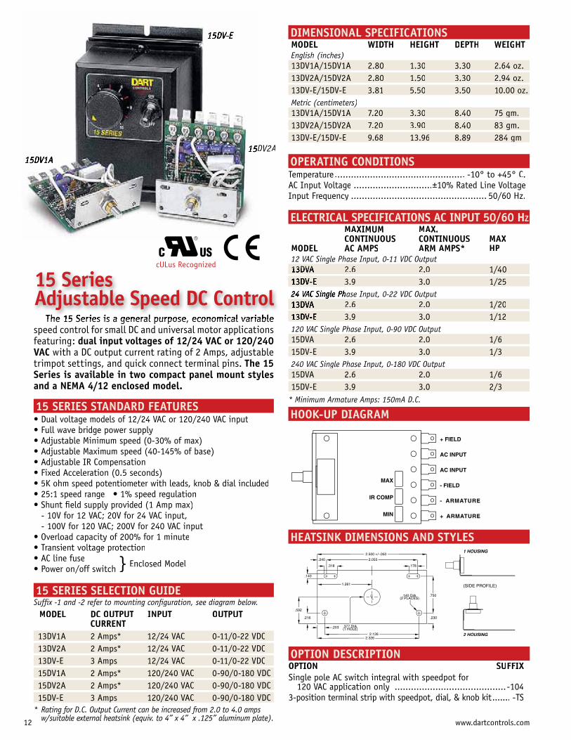
The 15 Series is a general purpose, economical variablespeed control for small DC and universal motor applications featuring: dual input voltages of 12/24 VAC or 120/240VAC with a DC output current rating of 2 Amps, adjustable trimpot settings, and quick connect terminal pins. The 15Series is available in two compact panel mount stylesand a NEMA 4/12 enclosed model.
15 SERIES STANDARD FEATURESDual voltage models of 12/24 VAC or 120/240 VAC input
15 SERIES SELECTION GUIDESuffix -1 and -2 refer to mounting configuration, see diagram below.
MODEL DC OUTPUT IT NPUT OT UTPUTCURRENT
p / /13DV1A 2 Amps* 12/24 VAC 0-11/0-22 VDCp / /13DV2A 2 Amps* 12/24 VAC 0-11/0-22 VDCp / /13DV-E 3 Amps 12/24 VAC 0-11/0-22 VDCp / /15DV1A 2 Amps* 120/240 VAC 0-90/0-180 VDCp / /15DV2A 2 Amps* 120/240 VAC 0-90/0-180 VDCp / /15DV-E 3 Amps 120/240 VAC 0-90/0-180 VDC
* Rating for D.C. Output Current can be increased from 2.0 to 4.0 amps w/suitable external heatsink (equiv. to 4” x 4” x .125” aluminum plate).
DIMENSIONAL SPECIFICATIONSMODEL WIDTH HEIGHT DEPTH WEIGHTEnglish (inches)
/13DV1A/15DV1A 2.80 1.30 3.30 2.64 oz./13DV2A/15DV2A 2.80 1.50 3.30 2.94 oz./13DV-E/15DV-E 3.81 5.50 3.50 10.00 oz.
Metric (centimeters)/13DV1A/15DV1A 7.20 3.30 g8.40 75 gm./13DV2A/15DV2A 7.20 3.90 g8.40 83 gm./13DV-E/15DV-E 9.68 13.96 g8.89 284 gm
OPERATING CONDITIONSTemperature................................................AC Input Voltage .............................±Input Frequency .................................................. 50/60 Hz.
ELECTRICAL SPECIFICATIONS AC INPUT 50/60 HZMAXIMUM MAX.CONTINUOUS CONTINUOUS MAX
MODEL AC AMPS ARM AMPS* HP12 VAC Single Phase Input, 0-11 VDC Output13DVA 2.6 2.0 /1/40
3.9 3.0 /1/25hase Input, 0-22 VDC Output2.6 2.0 /1/20
13DV E 3.9 3.0 /1/12120 VAC Single Phase Input, 0-90 VDC Output 15DVA 2.6 2.0 /1/615DV-E 3.9 3.0 /1/3240 VAC Single Phase Input, 0-180 VDC Output15DVA 2.6 2.0 /1/615DV-E 3.9 3.0 /2/3
* Minimum Armature Amps: 150mA D.C.
HOOK-UP DIAGRAM
HEATSINK DIMENSIONS AND STYLES
OPTION DESCRIPTIONOPTION SUFFIXSingle pole AC switch integral with speedpot for
120 VAC application only .........................................-1043-position terminal strip with speedpot, dial, & knob kit....... -TS
15 Series Adjustable Speed DC Control
+ FIELD
AC INPUT
AC INPUT
- FIELD
- ARMATURE
+ ARMATURE
MAX
IR COMP
MIN
} Enclosed Model
cULus Recognized
12 www.dartcontrols.com
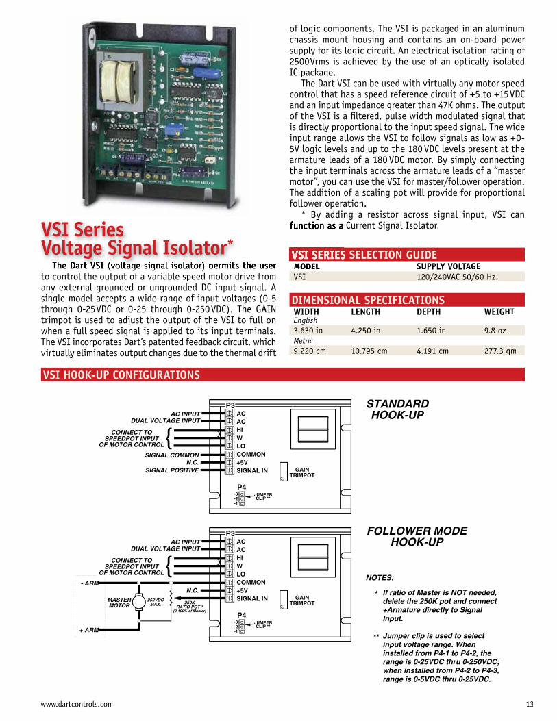
of logic components. The VSI is packaged in an aluminumchassis mount housing and contains an on-board power supply for its logic circuit. An electrical isolation rating of 2500Vrms is achieved by the use of an optically isolated IC package.
The Dart VSI can be used with virtually any motor speed
and an input impedance greater than 47K ohms. The output of the VSI is a filtered, pulse width modulated signal that is directly proportional to the input speed signal. The wide
5V logic levels and up to the 180 VDC levels present at thearmature leads of a 180 VDC motor. By simply connecting the input terminals across the armature leads of a “master motor”, you can use the VSI for master/follower operation. The addition of a scaling pot will provide for proportional follower operation.
* By adding a resistor across signal input, VSI can Current Signal Isolator.
VSI SERIES SELECTION GUIDE MODEL SUPPLY VOLTAGE VSI / /120/240VAC 50/60 Hz.
DIMENSIONAL SPECIFICATIONS WIDTH LENGTH DEPTH WEIGHT English 3.630 in 4.250 in 1.650 in 9.8 oz Metric
g 9.220 cm 10.795 cm 4.191 cm 277.3 gm
VSI HOOK-UP CONFIGURATIONS
The Dart VSI (voltage signal isolator) permits the user to control the output of a variable speed motor drive fromany external grounded or ungrounded DC input signal. Asingle model accepts a wide range of input voltages (0-5 through 0-25VDC or 0-25 through 0-250VDC). The GAIN trimpot is used to adjust the output of the VSI to full onwhen a full speed signal is applied to its input terminals.The VSI incorporates Dart’s patented feedback circuit, whichvirtually eliminates output changes due to the thermal drift
AC INPUTDUAL VOLTAGE INPUT
CONNECT TOSPEEDPOT INPUT
OF MOTOR CONTROL
SIGNAL COMMONN.C.
SIGNAL POSITIVE
If ratio of Master is NOT needed,delete the 250K pot and connect+Armature directly to SignalInput.
Jumper clip is used to selectinput voltage range. Wheninstalled from P4-1 to P4-2, therange is 0-25VDC thru 0-250VDC;when installed from P4-2 to P4-3,range is 0-5VDC thru 0-25VDC.
STANDARDHOOK-UP
P3ACACHIWLOCOMMON+5VSIGNAL IN
P4-3-2-1
JUMPERCLIP **
GAINTRIMPOT
FOLLOWER MODEHOOK-UP
{
*
**
NOTES:
250VDCMAX.
MASTERMOTOR 250K
RATIO POT *(0-100% of Master)
- ARM
+ ARM
AC INPUTDUAL VOLTAGE INPUT
CONNECT TOSPEEDPOT INPUT
OF MOTOR CONTROL
N.C.
P3ACACHIWLOCOMMON+5VSIGNAL IN
P4-3-2-1
JUMPERCLIP **
GAINTRIMPOT
{
VSI Series Voltage Signal Isolator*
13www.dartcontrols.com
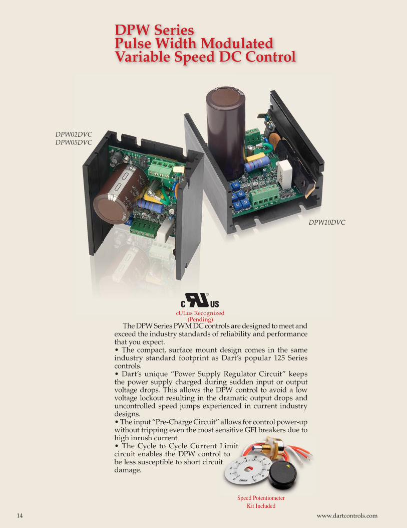
DPW Series Pulse Width Modulated Variable Speed DC Control
DPW02DVCDPW05DVC
DPW10DVC
2DVC5DVC
DPW10D
The DPW Series PWM DC controls are designed to meet and exceed the industry standards of reliability and performance that you expect. • The compact, surface mount design comes in the same industry standard footprint as Dart’s popular 125 Series controls. • Dart’s unique “Power Supply Regulator Circuit” keeps the power supply charged during sudden input or output voltage drops. This allows the DPW control to avoid a low voltage lockout resulting in the dramatic output drops and uncontrolled speed jumps experienced in current industry designs.• The input “Pre-Charge Circuit” allows for control power-up without tripping even the most sensitive GFI breakers due to high inrush current• The Cycle to Cycle Current Limit circuit enables the DPW control to be less susceptible to short circuit damage.
Limit l tot
Speed Potentiometer Kit Included
cULus Recognized (Pending)
14 www.dartcontrols.com
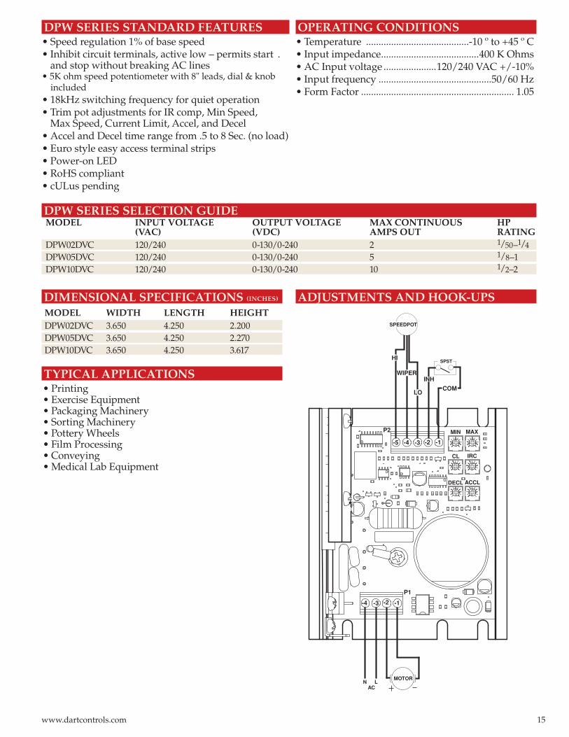
DPW SERIES STANDARD FEATURES• Speed regulation 1% of base speed • Inhibit circuit terminals, active low – permits start . and stop without breaking AC lines• 5K ohm speed potentiometer with 8" leads, dial & knob included• 18kHz switching frequency for quiet operation• Trim pot adjustments for IR comp, Min Speed, Max Speed, Current Limit, Accel, and Decel• Accel and Decel time range from .5 to 8 Sec. (no load)• Euro style easy access terminal strips• Power-on LED• RoHS compliant • cULus pending
SPST
SPEEDPOT
MOT OR L N
AC
P2
-1 -5 -3 -4
P1
-1 -2 -3 -4
-2
MIN MAX
CL IRC
DECL ACCL
WIPER
LO
HI
COM
INH
DPW SERIES SELECTION GUIDE MODEL INPUT VOLTAGE OUTPUT VOLTAGE MAX CONTINUOUS HP (VAC) (VDC) AMPS OUT RATING DPW02DVC 120/240 0-130/0-240 2 1/50–1/4
DPW05DVC 120/240 0-130/0-240 5 1/8–1 DPW10DVC 120/240 0-130/0-240 10 1/2–2
OPERATING CONDITIONS• Temperature .........................................-10 º to +45 º C• Input impedance .......................................400 K Ohms• AC Input voltage .....................120/240 VAC +/-10%• Input frequency .............................................50/60 Hz• Form Factor ............................................................. 1.05
DIMENSIONAL SPECIFICATIONS (INCHES)
MODEL WIDTH LENGTH HEIGHTDPW02DVC 3.650 4.250 2.200DPW05DVC 3.650 4.250 2.270DPW10DVC 3.650 4.250 3.617
TYPICAL APPLICATIONS• Printing• Exercise Equipment• Packaging Machinery• Sorting Machinery• Pottery Wheels• Film Processing• Conveying• Medical Lab Equipment
ADJUSTMENTS AND HOOK-UPS
15www.dartcontrols.com
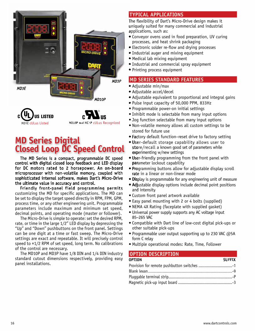
TYPICAL APPLICATIONSThe flexibility of Dart’s Micro-Drive design makes it uniquely suited for many commercial and industrial applications, such as:
processes, and heat shrink packaging
MD SERIES STANDARD FEATURES
stored for future use
re/recall a known good set of parameters while erimenting w/new settings
ameter lockout capability
e in a linear or non-linear mode
and intensity
85–265 VAC
other suitable pick-ups
form C relay
OPTION DESCRIPTIONOPTION SUFFIXProvision for remote pushbutton switches ............................-1Blank lexan......................................................................-9Pluggable terminal strip.....................................................-PMagnetic pick-up input board .............................................-3
Fr iendly front panel f ield programming permits customizing the MD for specific applications. The MD can be set to display the target speed directly in RPM, FPM, GPM, process time, or any other engineering unit. Programmableparameters include maximum and minimum set speed,decimal points, and operating mode (master or follower).
The Micro-Drive is simple to operate: set the desired RPM, rate, or time in the large 1/2” LED display by depressing the“Up” and “Down” pushbuttons on the front panel. Settings can be one digit at a time or fast sweep. The Micro-Drivesettings are exact and repeatable. It will precisely control speed to ±1/2 RPM of set speed, long term. No calibrationsof the control are necessary.
The MD10P and MD3P have 1/8 DIN and 1/4 DIN industrystandard cutout dimensions respectively, providing easy panel installations.
MD Series Digital Closed Loop DC Speed Control
MD3E cULus Listed cULus Recognized
16 www.dartcontrols.com
TachIte ValPage TachItem
ValuPage
3.622"
3.622
HOUSING DEPTH 4.625"
HOUSING DEPTH 4.625"
PANEL CUT-OUT
PANEL CUT-OUT
1.770"
MD3P
MD10P
MICRO-DRIVE
ENTER
MICRO-DRIVE
ENTER
CONTROLS
4.000"4.000"
.140" x 2
.140" x 4
0.885"
3.622"
0.811"
2.000"
CONTROLS
N
L
N
L
PICK-UP MOUNTEDTO MOTOR SHAFTblack
white
red
P1-1
P1-2
P1-3
P1-4
P1-5
P1-6
P1-7
P1-8
MDPMASTER
MOTOR
-ARM
+ARM
COMMON
+5VDC
SIGNAL
**INHIBIT
(Mounts on rotatingend shaft with 10-32
tapped hole, 1/2" deep)P1-9
P1-10
P1-11
P1-12
} Form CRelay Output(Programmable)
Alarm Output - Normally Open
Alarm Output - Common
Alarm Output - Normally Closed
**Jog Input
* For AC inputs utilizing two hot lines, both inputs should be protected with appropriately sized fuses or circuit breakers.
** P1-8 & P1-12 user input may be programmedfor a number of functions. Including (jog, inhibit, etc.)
COM (P1-5)
User Input 1
-A
+A
COM
+5V
S1
S2
NO
C
NC
IN1
P1-1
P1-2
P1-3
P1-4
P1-5
P1-6
P1-7
P1-8
P1-9
P1-10
P1-11
P1-12
MDPFOLLOWER
MOTOR
-ARM+ARM
**INHIBIT
} Form CRelay Output(Programmable)
Alarm Output - Normally Open
Alarm Output - Common
Alarm Output - Normally Closed
* For AC inputs utilizing two hot lines, both inputs should be protected with appropriately sized fuses or circuit breakers.
** P1-8 & P1-12 user input may be programmedfor a number of functions. Including (jog, inhibit, etc.)
COM (P1-5)
User Input 1
FOLLOWER PICK-UPMOUNTED TO
MOTOR SHAFTblack
white
red
(Mounts on rotatingend shaft with 10-32
tapped hole, 1/2" deep)
COMMON
+5VDC
SIGNAL 1SIGNAL 2
-A
+A
COM
+5V
S1
S2
NO
C
NC
IN1
black
white
AC INPUT
AC INPUT
MD10P = 7.5 Amp*MD3P = 15 Amp*
FUSE }85-265VAC
AC INPUT
AC INPUT
MD10P = 7.5 Amp*MD3P = 15 Amp*
FUSE }85-265VAC
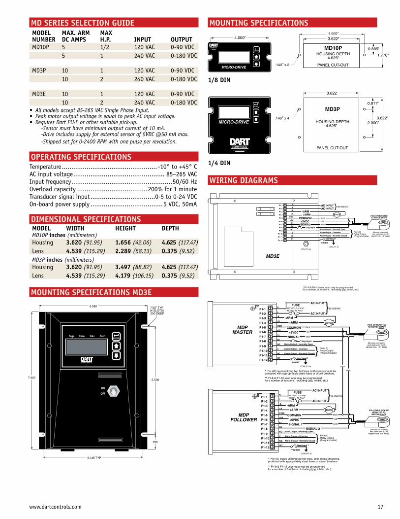
MD SERIES SELECTION GUIDE
MODEL MAX. ARM MAX NUMBER DC AMPS H.P. INPUT OUTPUT MD10P 5 1/2 120 VAC 0-90 VDC 5 1 240 VAC 0-180 VDC
MD3P 10 1 120 VAC 0-90 VDC 10 2 240 VAC 0-180 VDC
MD3E 10 1 120 VAC 0-90 VDC 10 2 240 VAC 0-180 VDC
-Sensor must have minimum output current of 10 mA. -Drive includes supply for external sensor of 5VDC @50 mA max. -Shipped set for 0-2400 RPM with one pulse per revolution.
OPERATING SPECIFICATIONSTemperature ..................................................AC input voltage ................................................ 85–265 VACInput frequency .....................................................50/60 HzOverload capacity .....................................Transducer signal input ..................................0-5 to 0-24 VDC On-board power supply ......................................5 VDC, 50mA
DIMENSIONAL SPECIFICATIONS MODEL WIDTH HEIGHT DEPTH MD10P inches (millimeters) Housing 3.620 (91.95) 1.656 (42.06) 4.625 (117.47) Lens 4.539 (115.29) 2.289 (58.13) 0.375 (9.52) MD3P inches (millimeters) Housing 3.620 (91.95) 3.497 (88.82) 4.625 (117.47) Lens 4.539 (115.29) 4.179 (106.15) 0.375 (9.52) MOUNTING SPECIFICATIONS MD3E
MOUNTING SPECIFICATIONS
WIRING DIAGRAMS
5.500
.750
5.125 TYP.
7/32" TYP.(4 SLOTS).350 DEEP
5.530
ON
OFF
7.400
CONTROLS
ENTERTachItem ValuPage
P1-12
P1-11
P1-4
P1-5
P1-6
P1-7
P1-8
P1-9
P1-10
P1-3
P1-2
P1-1
PICK-UP MOUNTEDTO MOTOR SHAFT
AC INPUTAC INPUT
black
white
red
MD3E
COMMON+5VDCSIGNAL
*INHIBIT
(Mounts on rotatingend shaft with 10-32
tapped hole, 1/2" deep)
} 85-265VAC
} Form CRelay Output(Programmable)
Alarm Output - Normally Open
Alarm Output - Common
Alarm Output - Normally Closed
*Jog Input
* P1-8 & P1-12 user input may be programmedfor a number of functions. Including (jog, inhibit, etc.)
COM (P1-5)
User Input 1
N
L
-A
+A
COM
+5V
S1
S2
NO
C
NC
IN1
-ARM+ARM MOTOR
Ground Lug
1/8 DIN
1/4 DIN
17www.dartcontrols.com
STANDARD FEATURES• 1/50 to 2.0 HP range• Universal power supply supports 85-265 VAC input• 1/8 or 1/4 DIN panel mount with NEMA 4X faceplate, or NEMA 4 stand-alone enclosure• Front panel fi eld-programming (with lock-out jumper)• Target and actual speed can be any engineering unit of measure• Two alarm relay outputs (form C, 5 Amp @ 250 VAC)• Large 1/2˝ LED display• Master/Follower modes• Displays set point or actual running speed• Adjustable PID settings
AVAILABLE OPTIONS• Custom faceplates for your Brand Name• Pluggable euro-style terminal strip• Provision for Remote Up/Down pushbutton switches
OPERATING SPECIFICATIONSAmbient Temp .............................................-10º to +45º CLine Input Frequency ........................................50/60 HzOverload Capacity .............................200% for 1 minuteTransducer Input .................................... 0-5 to 0-24 VDCOn-board transducerPower Supply ..............................................5 VDC, 50mA4-20mA input/output accuracy ............................... ± 1%
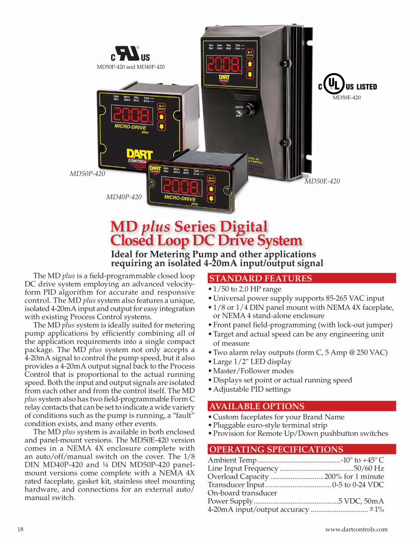
MD plus Series Digital Closed Loop DC Drive System
The MD plus is a fi eld-programmable closed loop DC drive system employing an advanced velocity-form PID algorithm for accurate and responsive control. The MD plus system also features a unique, isolated 4-20mA input and output for easy integration with existing Process Control systems.
The MD plus system is ideally suited for metering pump applications by effi ciently combining all of the application requirements into a single compact package. The MD plus system not only accepts a 4-20mA signal to control the pump speed, but it also provides a 4-20mA output signal back to the Process Control that is proportional to the actual running speed. Both the input and output signals are isolated from each other and from the control itself. The MD plus system also has two fi eld-programmable Form C relay contacts that can be set to indicate a wide variety of conditions such as the pump is running, a “fault” condition exists, and many other events.
The MD plus system is available in both enclosed and panel-mount versions. The MD50E-420 version comes in a NEMA 4X enclosure complete with an auto/off/manual switch on the cover. The 1/8 DIN MD40P-420 and ¼ DIN MD50P-420 panel-mount versions come complete with a NEMA 4X rated faceplate, gasket kit, stainless steel mounting hardware, and connections for an external auto/manual switch.
MD50P-420MD50E-420
MD40P-420
Ideal for Metering Pump and other applications requiring an isolated 4-20mA input/output signal
MD50E-420
MD50P-420 and MD40P-420
18 www.dartcontrols.com
MD plus SERIES SELECTION GUIDE MODEL MAX. ARM MAX NUMBER DC AMPS H.P. INPUT OUTPUTMD40P-420 5 ½ 120 VAC 0-90 VDC 5 1.0 240 VAC 0-180 VDC
MD50P-420 10 1.0 120 VAC 0-90 VDC 10 2.0 240 VAC 0-180 VDC
MD50E-420 10 1.0 120 VAC 0-90 VDC 10 2.0 240 VAC 0-180VDC
DIMENSIONS (INCHES) MODEL WIDTH HEIGHT DEPTH MD40P-420 (1/8 DIN)Housing 3.620 1.656 4.625Lens 4.539 2.289 0.375
MD50P-420 (1/4 DIN)Housing 3.620 3.497 4.625Lens 4.539 4.179 0.375
MD50E-420 (NEMA 4 enclosed)Same dimensions as MD3E on catalog page 17
APPLICATIONSThe MD plus system is ideal in many process
applications requiring a closed-loop DC variable speed drive with an isolated 4-20mA input and output.
Typical applications include:• Waste water treatment• Chemical metering processes• Laboratory mixing equipment• Industrial auger/mixing equipment• Polymer injection processes
ASP40-420The ASP40-420 is also available for applications that
require a closed-loop digital interface with a 4-20mA input/output and programmable relay outputs, but already have an existing AC or DC drive in the system.
See your Dart Representative for details or call Dart Controls at 317-873-5211.
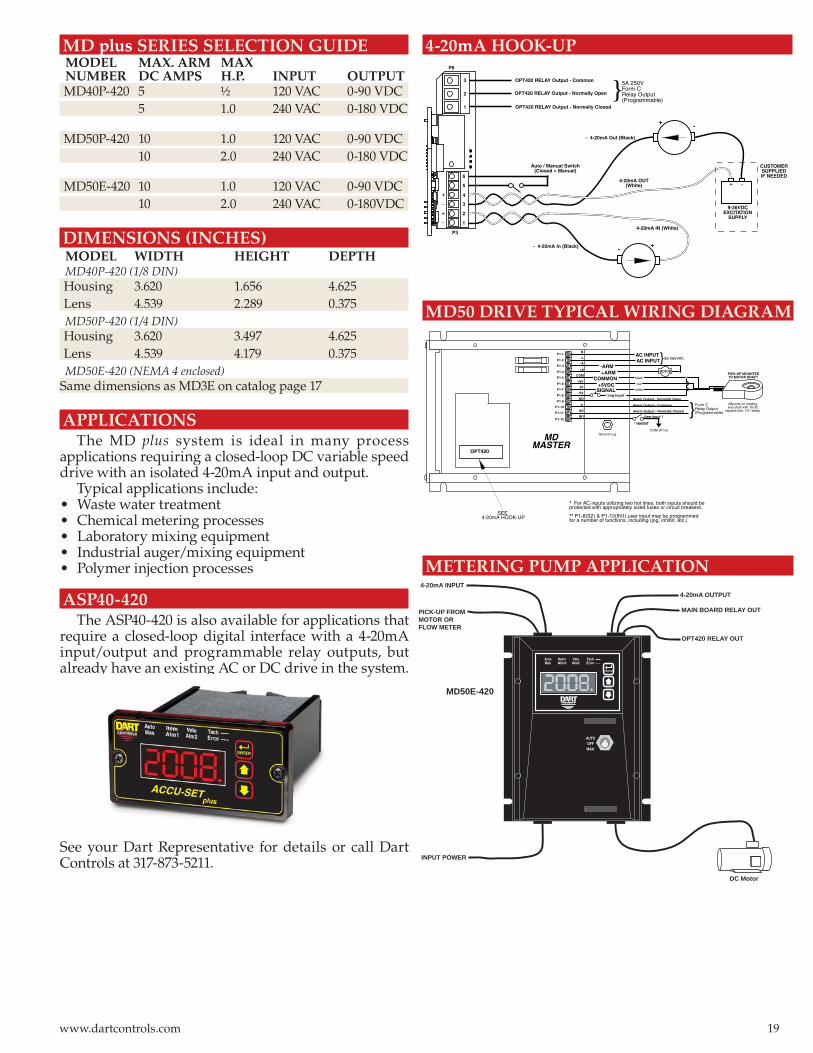
METERING PUMP APPLICATION
4-20mA HOOK-UP
MD50 DRIVE TYPICAL WIRING DIAGRAM
DC Motor
INPUT POWER
PICK-UP FROMMOTOR ORFLOW METER
4-20mA INPUT4-20mA OUTPUT
MAIN BOARD RELAY OUT
OPT420 RELAY OUT
MD50E-420
AUTOOFF
CONTROLS
ENTER
TachItem ValuAutoAlm1 Alm2Man Error ---
MAN
P1-12
P1-11
P1-4
P1-5
P1-6
P1-7
P1-8
P1-9
P1-10
P1-3
P1-2
P1-1
PICK-UP MOUNTED TO MOTOR SHAFT
AC INPUTAC INPUT
black
white
red
MDMASTER
COMMON +5VDC
SIGNAL
**INHIBIT
(Mounts on rotating end shaft with 10-32
tapped hole, 1/2" deep)
}85-265VAC
} Form C Relay Output (Programmable)
Alarm Output - Normally Open
Alarm Output - Common
Alarm Output - Normally Closed
*Jog Input
COM (P1-5)
User Input 1
N
L
-A
+A
COM
+5V
S1
S2
NO
C
NC
IN1
-ARM +ARM MOTOR
Ground Lug
* For AC inputs utilizing two hot lines, both inputs should be protected with appropriately sized fuses or circuit breakers.
** P1-8(S2) & P1-12(IN1) user input may be programmedfor a number of functions, including (jog, inhibit, etc.)
OPT420
SEE 4-20mA HOOK-UP
}5A 250VForm CRelay Output(Programmable)
OPT420 RELAY Output - Normally Open
OPT420 RELAY Output - Common
OPT420 RELAY Output - Normally Closed
Auto / Manual Switch(Closed = Manual)
4-20mA OUT(White)
- 4-20mA Out (Black)
4-20mA IN (White)
- 4-20mA In (Black)
P3
P6
+ -
9-36VDCEXCITATION
SUPPLY 1
2
3
4
5
6
+
-
+
-
1
2
3
CUSTOMERSUPPLIEDIF NEEDED
+-
+-
19www.dartcontrols.com
STANDARD fEATURES• Compact 1/8 or 1/4 DIN sturdy aluminum housing for panel mounting; or NEMA 4/12 enclosure• Microprocessor based; utilizes powerful 16-bit Motorola C68HC11• Field Programmable operating parameters• Displays actual or desired speed directly in RPM, FPM, process time, or other engineering units• P-I-D digital closed loop control; gains setable for optimum system performance; Fast settling time• Accuracy ±1/2 RPM of set speed• Master/Follower operation• Variety of pick-up inputs; Hall-Effect, Photoelectric, or any TTL; control accepts up to 1.2 million pulses/min. max• Non-volatile memory retains speed setting and all field programmable parameters• Internal A/D interface permits using potentiometer, 4 to 20mA or 0 to +5 VDC signal in lieu of digital pick-up signal or to control target speed, current program or frequency generator output• Inhibit circuit permits start and stop without breaking AC lines; pre-selecting speed, or simultaneous start-up of multiple control units• Up/down pushbuttons for set points - slow-fast sweep; front panel lockout prevents accidental setting changes• Self-contained power supply for transducer (+5V, 25mA)• Transient voltage protection• Exclusive user assignable outputs - to drive relays, alarms, etc. Can be activated by any combination of conditions; upper speed limit exceeded, etc.• Independent frequency generator allows units to produce own leader frequency.• European style terminal strip• G.E. Lexan™ membrane seals faceplate from environment• Multi-mode of operation allows multiple constants, settings, and upper/lower limits. Up to six different configurations can be selected from the front panel via the up/down pushbutton switches
PROgRAMMINg fEATURES• All programming from front panel “Menu Driven”• User selectable “programming protect” prevents unauthorized access• LED function indicators• Programmable parameters include: - Lower/upper limits for speed setting - Accel/decel 0 to 30 seconds for 0-1000 RPM change - Pick-up pulses per revolution - P-I-D gain settings - Constants to allow display in desired user engineering units - rate or time - Decimal point or colon - “Stall detector” time-out for annunciation and shutdown - Multiple programs permit up to six different desired set-ups to be programmed - Selectable display blanking point - Operation mode (master rate, master time, standard follower, Network Follower) - Unit address for multiple control networking - Selectable serial communication rate - Front panel lockout for speed setting and/or program changes - Numerous other features
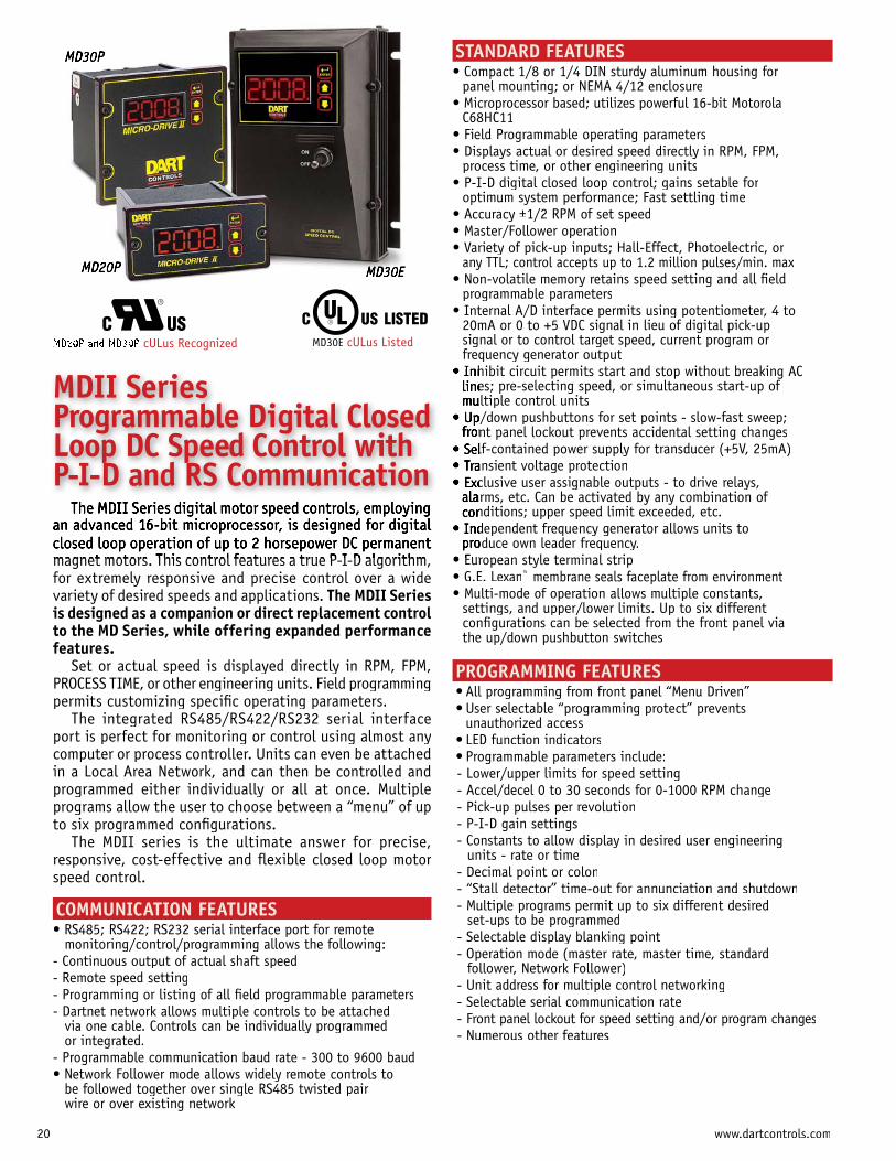
magnet motors. This control features a true P-I-D algorithm, for extremely responsive and precise control over a wide variety of desired speeds and applications. The MDII Series is designed as a companion or direct replacement control to the MD Series, while offering expanded performance features.
Set or actual speed is displayed directly in RPM, FPM, PROCESS TIME, or other engineering units. Field programming permits customizing specific operating parameters.
The integrated RS485/RS422/RS232 serial interface port is perfect for monitoring or control using almost any computer or process controller. Units can even be attached in a Local Area Network, and can then be controlled and programmed either individually or all at once. Multiple programs allow the user to choose between a “menu” of up to six programmed configurations.
The MDII series is the ultimate answer for precise, responsive, cost-effective and flexible closed loop motor speed control.
COMMUNICATION fEATURES• RS485; RS422; RS232 serial interface port for remote
monitoring/control/programming allows the following:- Continuous output of actual shaft speed- Remote speed setting- Programming or listing of all field programmable parameters- Dartnet network allows multiple controls to be attached
via one cable. Controls can be individually programmed or integrated.
- Programmable communication baud rate - 300 to 9600 baud• Network Follower mode allows widely remote controls to
be followed together over single RS485 twisted pair wire or over existing network
MD30E
MD30P
MD20P
• Inhibit circuit permits start and stop without breaking AC lines; pre-selecting speed, or simultaneous start-up of multiple control units• Up/down pushbuttons for set points - slow-fast sweep; front panel lockout prevents accidental setting changes• Self-contained power supply for transducer (+5V, 25mA)• Transient voltage protection• Exclusive user assignable outputs - to drive relays, alarms, etc. Can be activated by any combination of conditions; upper speed limit exceeded, etc.• Independent frequency generator allows units to produce own leader frequency.• European style terminal strip
The MDII Series digital motor speed controls, employing an advanced 16-bit microprocessor, is designed for digital closed loop operation of up to 2 horsepower DC permanent magnet motors. This control features a true P-I-D algorithm,
MDII Series Programmable Digital Closed Loop DC Speed Control with P-I-D and RS Communication
MD30E cULus ListedMD20P and MD30P cULus Recognized
20 www.dartcontrols.com
5.500
.750
5.125 TYP.
7/32" TYP(4 SLOTS).350 DEEP
5.530
ON
OFF
7.400
CONTROLS
ENTERTachItem ValuPage
3.622"
HOUSING DEPTH 4.625"
PANEL CUT-OUT
.885"MD20P
MICRO-DRIVE II
ENTER
CONTROLS
4.000"
TachItem ValuPage
4.000"
Dia .140" x 2
1.770"
PICK-UP MOUNTEDTO MOTOR SHAFT
AC INPUT
AC INPUT
black
white
red
P1-1
P1-2
P1-3
P1-4
P1-5
P1-6
P1-7
P1-8
* MD20P = 7.5 Amp MD30P = 15 Amp
FUSE*
MOTOR
-ARM
+ARM
COMMON
+5VDC
SIGNAL 1
OPTIONALINHIBITSWITCH
(Mounts on rotatingend shaft with 10-32
tapped hole, 1/2" deep)P1-9
P1-10
P1-11
P1-12
} 85-265VAC
UNUSED
UNUSED
UNUSED
UNUSED
COM (P1-5)
MDII SERIES SELECTION GUIDE
MODEL MAX. ARM MAXNUMBER DC AMPS H.P. INPUT OUTPUT MD20P 5 1/2 120 VAC 0-90 VDC 5 1 240 VAC 0-180 VDC
MD30P 10 1 120 VAC 0-90 VDC 10 2 240 VAC 0-180 VDC
MD30E 10 1 120 VAC 0-90 VDC 10 2 240 VAC 0-180 VDC
• All models accept 85-265 VAC Single Phase Input.• Peak motor output voltage is equal to peak AC input voltage.• Requires Dart PU-E or other suitable pick-up. -Sensor must have minimum output current of 10 mA. -Drive includes supply for external sensor of 5VDC @25 mA max. -Shipped set for 0-2400 RPM with one pulse per revolution.
OPTION DESCRIPTIONOPTION SUFFIXAuto-Off-Manual control for 4-20mA or 0-5 VDC analog signal input (MD30E only) .................................................-7Magnetic pick-up input board ...............................................-3Blank Lexan (MD20P, MD30P) ..............................................-9Pluggable terminal strip .........................................................-P
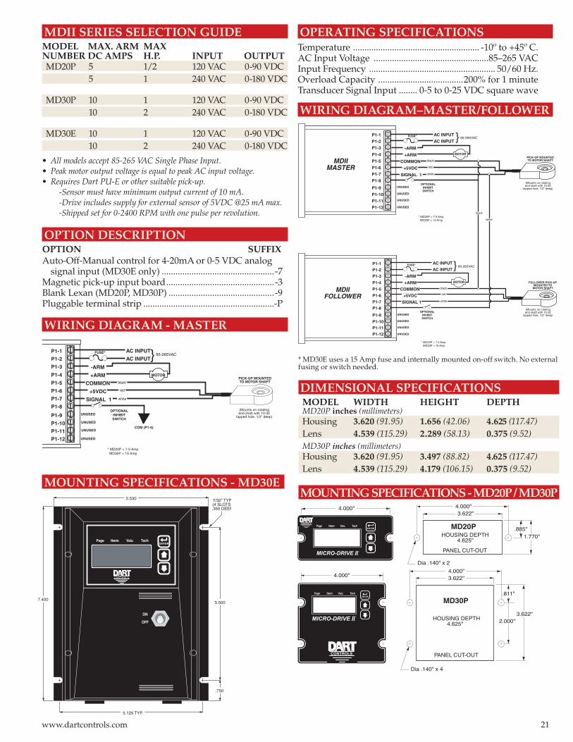
WIRING DIAGRAM - MASTER
WIRING DIAGRAM–MASTER/FOLLOWER
* MD30E uses a 15 Amp fuse and internally mounted on-off switch. No external fusing or switch needed.
DIMENSIONAL SPECIFICATIONS MODEL WIDTH HEIGHT DEPTH MD20P inches (millimeters) Housing 3.620 (91.95) 1.656 (42.06) 4.625 (117.47) Lens 4.539 (115.29) 2.289 (58.13) 0.375 (9.52) MD30P inches (millimeters) Housing 3.620 (91.95) 3.497 (88.82) 4.625 (117.47) Lens 4.539 (115.29) 4.179 (106.15) 0.375 (9.52)
MOUNTING SPECIFICATIONS - MD20P / MD30P
OPERATING SPECIFICATIONSTemperature ....................................................... -10º to +45º C.AC Input Voltage ..................................................85–265 VACInput Frequency ....................................................... 50/60 Hz.Overload Capacity .....................................200% for 1 minuteTransducer Signal Input ........ 0-5 to 0-25 VDC square wave
MOUNTING SPECIFICATIONS - MD30E
3.622"
HOUSING DEPTH 4.625"
PANEL CUT-OUT
MD30P
3.622"MICRO-DRIVE II
ENTER
TachItem ValuPage
4.000"4.000"
Dia .140" x 4
.811"
2.000"
CONTROLS
PICK-UP MOUNTEDTO MOTOR SHAFT
AC INPUT
AC INPUT
black
white
red
P1-1
P1-2
P1-3
P1-4
P1-5
P1-6
P1-7
P1-8
MDIIMASTER
* MD20P = 7.5 Amp MD30P = 15 Amp
FUSE*
MOTOR
-ARM
+ARM
COMMON
+5VDC
SIGNAL 1
OPTIONALINHIBITSWITCH
(Mounts on rotatingend shaft with 10-32
tapped hole, 1/2" deep)
(Mounts on rotatingend shaft with 10-32
tapped hole, 1/2" deep)
P1-9
P1-10
P1-11
P1-12
} 85-265VAC
UNUSED
UNUSED
UNUSED
UNUSED
P1-1
P1-2
P1-3
P1-4
P1-5
P1-6
P1-7
P1-8
P1-9
P1-10
P1-11
P1-12
MDIIFOLLOWER
AC INPUT
AC INPUTFUSE*
MOTOR
-ARM
+ARM
UNUSED
UNUSED
UNUSED
FOLLOWER PICK-UPMOUNTED TO
MOTOR SHAFTblack
white
red
COMMON
+5VDC
SIGNAL 1
} 85-265VAC
UNUSED
* MD20P = 7.5 Amp MD30P = 15 Amp
OPTIONALINHIBITSWITCH
white
black
21www.dartcontrols.com

and precise, digital closed loop motor speed control. Anon-board microprocessor with non-volatile memory coupledwith sophisticated internal software makes Dart’s Accu-Setthe ultimate in accuracy and control.
Target speeds are displayed directly in RPM, FPM, GPM, process time, or any other engineering unit of measure.Friendly front-panel field programming permits customizing
maximum and minimum set speed, decimal points or colon, operating mode (master or follower), and the constant which takes into account motor gear ratios.
The Accu-Set is simple to operate… just set thedesired RPM, rate, or time in the large 1/2” LED display ”by depressing the “up-down” pushbuttons, one digit at a time or fast sweep. The Accu-Set settings are exact andrepeatable. It will precisely control speed to a remarkable ±1/2 RPM of set speed, long term.
The panel mount unit is easy to install in the industry standard cutout dimensions of 1/8 DIN. All wiring connects directly to a European style terminal strip through the easyaccess rear panel.
TYPICAL APPLICATIONSDart’s Accu-Set design is ideal for providing the same
precise closed loop control and digital readout as the MDSeries Micro-Drive in new or retro-fit applications that use an AC, DC, or Brushless DC motor drive system.
OPERATING SPECIFICATIONSTemperature...........................................AC input voltage.........................................85–265 VACInput frequency ............................................ 50/60 HzTransducer signal input..........................0-5 to 0-24 VDC On-board power supply.............................. 5 VDC, 50mA(for external sensors)
Display adjustable for intensity, decimal point positions, and zero blanking
User can program all configurations through easy-to-use front panel pushbutton switches
New universal power supply will support any AC input voltage from 85 to 265 VAC
Accu-Set Series Digital Closed Loop Inter-face for Improved AC or DC Drive System Performance
E t ll l
22 www.dartcontrols.com
TachIte ValPage TachItem
ValuPage
3.622"
HOUSING DEPTH 4.625"
PANEL CUT-OUT
1.770"
ASP10
MICRO-DRIVEACCU-SET
ENTER
CONTROLS
4.000"4.000"
.140" x 2
0.885"
ASP CONFIGURATIONS
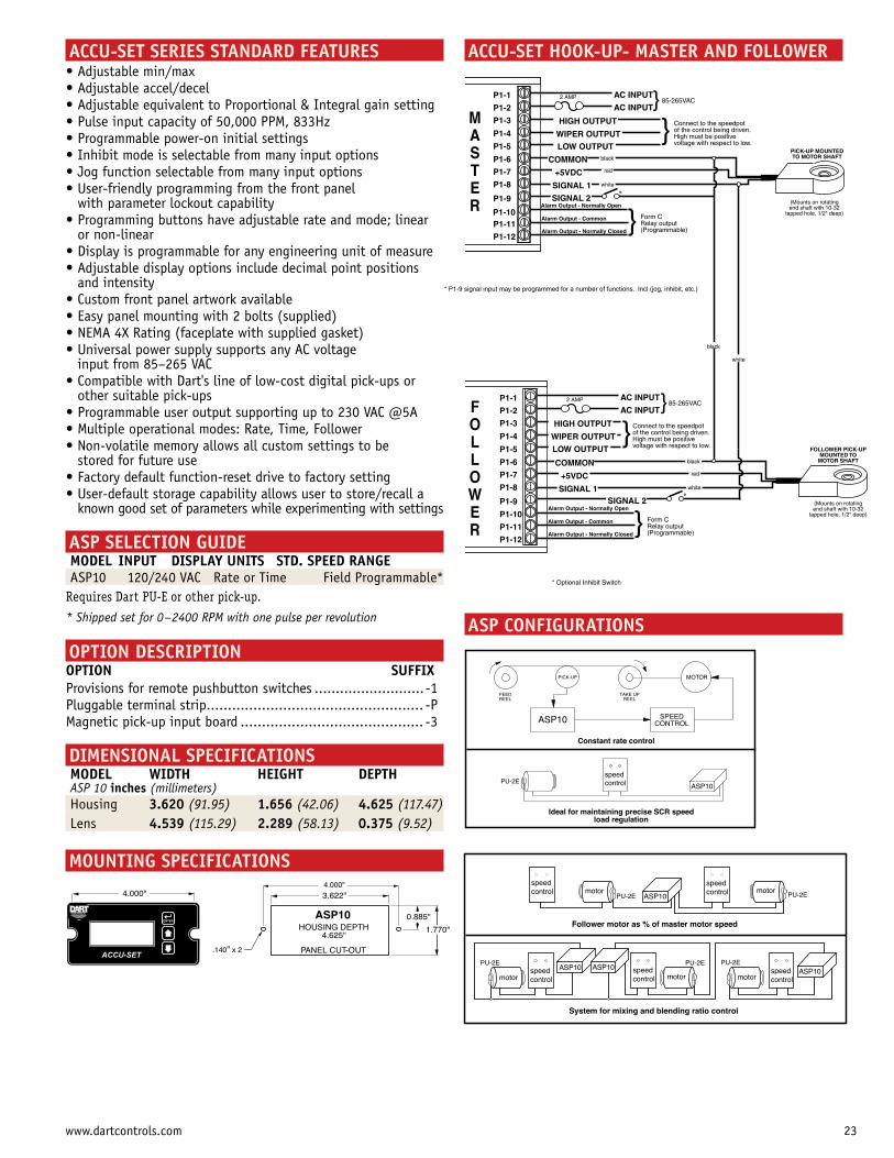
ACCU-SET HOOK-UP- MASTER AND FOLLOWERACCU-SET SERIES STANDARD FEATURES
with parameter lockout capability
or non-linear
and intensity
input from 85–265 VAC
other suitable pick-ups
stored for future use
known good set of parameters while experimenting with settings
ASP SELECTION GUIDE MODEL INPUT DISPLAY UNITS STD. SPEED RANGE ASP10 120/240 VAC Rate or Time Field Programmable*
Requires Dart PU-E or other pick-up.
* Shipped set for 0–2400 RPM with one pulse per revolution
OPTION DESCRIPTIONOPTION SUFFIXProvisions for remote pushbutton switches ..........................-1Pluggable terminal strip................................................... -PMagnetic pick-up input board ........................................... -3
DIMENSIONAL SPECIFICATIONS MODEL WIDTH HEIGHT DEPTH ASP 10 inches (millimeters) Housing 3.620 (91.95) 1.656 (42.06) 4.625 (117.47) Lens 4.539 (115.29) 2.289 (58.13) 0.375 (9.52)
MOUNTING SPECIFICATIONS
motorspeedcontrol ASP10
PU-2E
Ideal for maintaining precise SCR speed load regulation
Constant rate control
PICK-UP MOTOR
TAKE UP REEL
FEED REEL
ASP10 SPEEDCONTROL
motorspeedcontrol
ASP10PU-2Emotor
PU-2E
speedcontrol
motorspeedcontrol motor
speedcontrol motor
speedcontrol
ASP10PU-2EPU-2EPU-2E ASP10
Follower motor as % of master motor speed
System for mixing and blending ratio control
ASP10
PICK-UP MOUNTEDTO MOTOR SHAFT
AC INPUT
AC INPUT
black
white
red
P1-1
P1-2
P1-3
P1-4
P1-5
P1-6
P1-7
P1-8
ASPASTER
2 AMP
HIGH OUTPUT
WIPER OUTPUT
COMMON
+5VDC
SIGNAL 1
(Mounts on rotatingend shaft with 10-32
tapped hole, 1/2" deep)
P1-9
P1-10P1-11
P1-12
} 85-265VAC
} Form CRelay output(Programmable)
Alarm Output - Normally Open
Alarm Output - Common
Alarm Output - Normally Closed
* P1-9 signal input may be programmed for a number of functions. Incl (jog, inhibit, etc.)
P1-1
P1-2
P1-3
P1-4
P1-5
P1-6
P1-7
P1-8
P1-9
P1-10
P1-11
P1-12
ASPOLLOWER
* Optional Inhibit Switch
FOLLOWER PICK-UPMOUNTED TO
MOTOR SHAFTblack
white
red
(Mounts on rotatingend shaft with 10-32
tapped hole, 1/2" deep)
white
COMMON
+5VDC
SIGNAL 1SIGNAL 2
SIGNAL 2*
LOW OUTPUT} Connect to the speedpot
of the control being driven.High must be positivevoltage with respect to low.
} Form CRelay output(Programmable)
Alarm Output - Normally Open
Alarm Output - Common
Alarm Output - Normally Closed
AC INPUT
AC INPUT2 AMP
HIGH OUTPUT
WIPER OUTPUT
}85-265VAC
LOW OUTPUT}Connect to the speedpot
of the control being driven.High must be positivevoltage with respect to low.
*
black
M A S T E R
F O L L O W E R
23www.dartcontrols.com

ACCU-SET II SERIES STANDARD FEATURES
MC68HC11
process time, or other engineering units
±1/2 RPM of set speed
programmable parameters
signal or to control target speed, current program or frequency generator output
of multiple control units
front panel lockout prevents accidental setting changes
alarms, etc. Can be activated by any combination of
produce own leader frequency.
G.E. Lexan™ membrane seals faceplate from environment
settings, and upper/lower limits. Up to six different configurations can be selected from the front panel via the up/down pushbutton switches
PROGRAMMING FEATURES”
unauthorized access
- Lower/upper limits for speed setting- Accel/decel 0 to 30 seconds for 0-1000 RPM change- Pick-up pulses per revolution- P-I-D gain settings- Constants to allow display in desired user engineering units– rate or time- Decimal point or colon- “Stall detector” time-out for annunciation and shutdown- Multiple programs permit up to six different desired set-ups to be programmed- Selectable display blanking point- Operation mode (master rate, master time, standard follower, network follower)- Unit address for multiple control networking- Selectable serial communication rate- Front panel lockout for speed setting and/or program changes- Numerous other features
to provide: LED display of set or actual speed, closed loop motor speed control, Master or Follower modes, andSerial communications.
The Accu-Set II Series is a companion control to the Accu-Set Series, while offering significantly improvedperformance. This control features a true P-I-D algorithm, for extremely responsive and precise control over a widevariety of desired speeds and applications.
Set or actual speed is displayed directly in RPM, FPM,Process Time, or other engineering units. Field programmingpermits customizing specific operating parameters.
The integrated RS485/RS422/RS232 serial interfaceport is perfect for monitoring or control using almost anycomputer or process controller. Units can even be attached in a Local Area Network, and can then be controlled andprogrammed either individually or all at once. Multiple programs allow the user to choose between a “menu” of up to six programmed configurations.
The Accu-Set II Series is ideally suited for commercial or industrial applications, including system up-grades.
COMMUNICATION FEATURES
monitoring/control/programming allows the following:- Continuous output of actual shaft speed- Remote speed setting- Programming or listing of all field programmable
parameters- Dartnet network allows multiple controls to be attached
via one cable. Controls can be individually programmed or integrated.
- Programmable communication baud rate for 300 to 9600 baud
- Network Follower mode allows widely remote controls tobe followed together over single RS485 twisted pair wireor over existing network
Accu-SetII Series Digital Closed Loop System for Use with Conventional AC Frequency or DC Drives
24 www.dartcontrols.com
PU-2E PU-2E
motorspeedcontrol motor
speedcontrol motor
speedcontrol
ASP20PU-2EPU-2EPU-2E ASP20
Follower motor as % of master motor speed
System for mixing and blending ratio control
ASP20
motorspeedcontrol ASP20
PU-2E
Ideal for maintaining precise SCR speed load regulation
Constant rate control
PICK-UP MOTOR
TAKE UP REEL
FEED REEL
ASP20 SPEEDCONTROL
speedcontrol motor
speedcontrol ASP20
motor
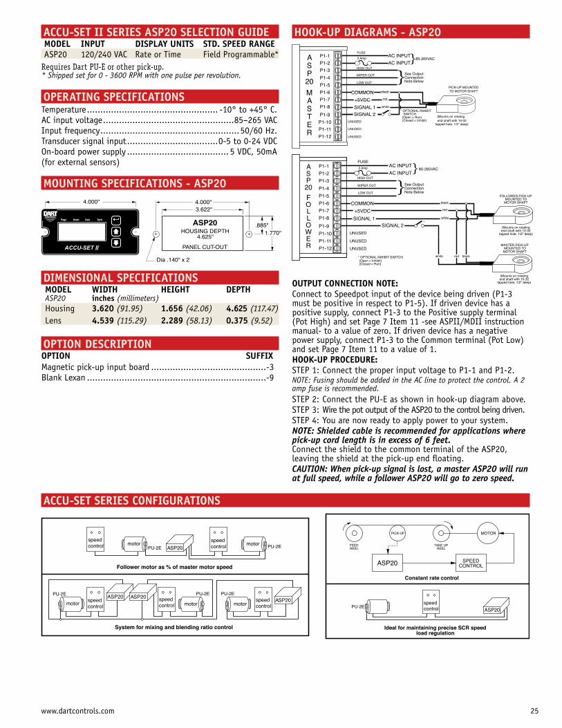
}See OutputConnectionNote Below
HIGH OUT
WIPER OUT
LOW OUT
P1-1
P1-2
P1-3
P1-4
P1-5
P1-6
P1-7
P1-8
P1-9
P1-10
P1-11
P1-12
AC INPUT
AC INPUT2 Amp
FUSE
FOLLOWER PICK-UPMOUNTED TO
MOTOR SHAFTblack
white
red
(Mounts on rotatingend shaft with 10-32
tapped hole, 1/2" deep)
MASTER PICK-UPMOUNTED TO
MOTOR SHAFT
(Mounts on rotatingend shaft with 10-32
tapped hole, 1/2" deep)
blackwhite red
COMMON
+5VDC
SIGNAL 1
}85-265VAC
SIGNAL 2
* OPTIONAL INHIBIT SWITCH (Open = Inhibit)(Closed = Run)
*
UNUSED
UNUSED
UNUSED
ASP20
FOLLOWERMICRO-DRIVEACCU-SET II
CONTROLS
4.000"
TachItem ValuPage
3.622"
HOUSING DEPTH 4.625"
PANEL CUT-OUT
.885"ASP20
4.000"
Dia .140" x 2
1.770"
HOOK-UP DIAGRAMS - ASP20ACCU-SET II SERIES ASP20 SELECTION GUIDE MODEL INPUT DISPLAY UNITS STD. SPEED RANGE ASP20 120/240 VAC Rate or Time Field Programmable*Requires Dart PU-E or other pick-up.* Shipped set for 0 - 3600 RPM with one pulse per revolution.
OPERATING SPECIFICATIONSTemperature .................................................AC input voltage .................................................85–265 VACInput frequency ....................................................50/60 Hz.Transducer signal input ..................................0-5 to 0-24 VDC On-board power supply ...................................... 5 VDC, 50mA(for external sensors)
MOUNTING SPECIFICATIONS - ASP20
DIMENSIONAL SPECIFICATIONS MODEL WIDTH HEIGHT DEPTH ASP20 inches (millimeters) Housing 3.620 (91.95) 1.656 (42.06) 4.625 (117.47) Lens 4.539 (115.29) 2.289 (58.13) 0.375 (9.52)
OPTION DESCRIPTIONOPTION SUFFIXMagnetic pick-up input board ...........................................-3Blank Lexan ...................................................................-9
ACCU-SET SERIES CONFIGURATIONS
PICK-UP MOUNTEDTO MOTOR SHAFT
AC INPUT
AC INPUT
black
white
red
P1-1
P1-2
P1-3
P1-4
P1-5
P1-6
P1-7
P1-8
2 Amp
FUSE
COMMON
+5VDC
SIGNAL 1
(Mounts on rotatingend shaft with 10-32
tapped hole, 1/2" deep)
P1-9
P1-10
P1-11
P1-12
}85-265VAC
SIGNAL 2
}See OutputConnectionNote Below
HIGH OUT
WIPER OUT
LOW OUT
* OPTIONAL INHIBIT SWITCH
(Open = Run)(Closed = Inhibit)
*
UNUSED
UNUSED
UNUSED
ASP20
MASTER
OUTPUT CONNECTION NOTE:Connect to Speedpot input of the device being driven (P1-3 must be positive in respect to P1-5). If driven device has a positive supply, connect P1-3 to the Positive supply terminal (Pot High) and set Page 7 Item 11 -see ASPII/MDII instruction manual- to a value of zero. If driven device has a negative power supply, connect P1-3 to the Common terminal (Pot Low) and set Page 7 Item 11 to a value of 1.HOOK-UP PROCEDURE:STEP 1: Connect the proper input voltage to P1-1 and P1-2.NOTE: Fusing should be added in the AC line to protect the control. A 2 amp fuse is recommended.STEP 2: Connect the PU-E as shown in hook-up diagram above.STEP 3: Wire the pot output of the ASP20 to the control being driven.STEP 4: You are now ready to apply power to your system.NOTE: Shielded cable is recommended for applications where pick-up cord length is in excess of 6 feet. Connect the shield to the common terminal of the ASP20, leaving the shield at the pick-up end floating.CAUTION: When pick-up signal is lost, a master ASP20 will run at full speed, while a follower ASP20 will go to zero speed.
25www.dartcontrols.com
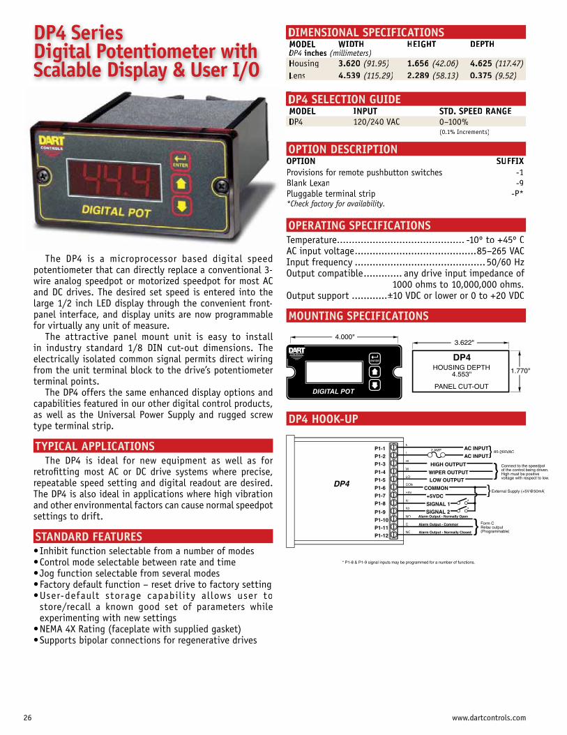
DIMENSIONAL SPECIFICATIONSMODEL WIDTH HEIGHT DEPTHDP4 inches (millimeters)Housingg 3.620 (91.95)( ) 1.656 (42.06)( ) 4.625 (117.47)( )Lens 4.539 ( )(115.29) 2.289 ( )(58.13) 0.375 ( )(9.52)
DP4 SELECTION GUIDEMODEL INPUT STD. SPEED RANGE
OPTION DESCRIPTIONOPTION SUFFIXProvisions for remote pushbutton switches -1Blank Lexan -9Pluggable terminal strip -P**Check factory for availability.
OPERATING SPECIFICATIONSTemperature...........................................AC input voltage.........................................85–265 VACInput frequency ............................................50/60 HzOutput compatible............. any drive input impedance of
1000 ohms to 10,000,000 ohms.Output support ............±
MOUNTING SPECIFICATIONS
DP4 HOOK-UP
3.622"
HOUSING DEPTH 4.553"
PANEL CUT-OUT
1.770"
DP4
DIGITAL POT
ENTER
CONTROLS
4.000"
DP4 Series Digital Potentiometer with Scalable Display & User I/O
The DP4 is a microprocessor based digital speed potentiometer that can directly replace a conventional 3-wire analog speedpot or motorized speedpot for most AC and DC drives. The desired set speed is entered into thelarge 1/2 inch LED display through the convenient front-panel interface, and display units are now programmable for virtually any unit of measure.
The attractive panel mount unit is easy to install in industry standard 1/8 DIN cut-out dimensions. Theelectrically isolated common signal permits direct wiringfrom the unit terminal block to the drive’s potentiometer terminal points.
The DP4 offers the same enhanced display options andcapabilities featured in our other digital control products, as well as the Universal Power Supply and rugged screwtype terminal strip.
TYPICAL APPLICATIONSThe DP4 is ideal for new equipment as well as for
retrofitting most AC or DC drive systems where precise,repeatable speed setting and digital readout are desired. The DP4 is also ideal in applications where high vibration and other environmental factors can cause normal speedpotsettings to drift.
STANDARD FEATURES
store/recall a known good set of parameters while experimenting with new settings
AC INPUT
AC INPUTP1-1
P1-2
P1-3
P1-4
P1-5
P1-6
P1-7
P1-8
DP4
2 AMP
HIGH OUTPUT
WIPER OUTPUT
COMMON
+5VDC
SIGNAL 1
P1-9
P1-10
P1-11
P1-12
} 85-265VAC
} Form CRelay output(Programmable)
Alarm Output - Normally Open
Alarm Output - Commonp
Alarm Output - Normally Closedp y
* P1-8 & P1-9 signal inputs may be programmed for a number of functions.
SIGNAL 2*
LOW OUTPUT} Connect to the speedpot
of the control being driven.High must be positivevoltage with respect to low.
*
}External Supply (+5V@50mA)
N
L
HI
W
LO
COM
+5V
S1
S2
NO
C
NC
26 www.dartcontrols.com
Cascade Out
MasterSpeedpot
Cascade In Cascade In
Common Common Common
MSC # 1 MSC # 3MSC # 2
approx. 5K
SPEEDPOT HI+ ARMATURE- ARMATURE+ FIELD- FIELDSPARESPAREAC INPUTAC INPUT
SPEEDPOT LOSPEEDPOT WIPER
RATIOCONTROL
HIGH
WIPER
LOW
FROMMSC
CONTROL UNIT(i.e. 500, 250, 125 SERIES
250KOHM
10K-
incr
ease
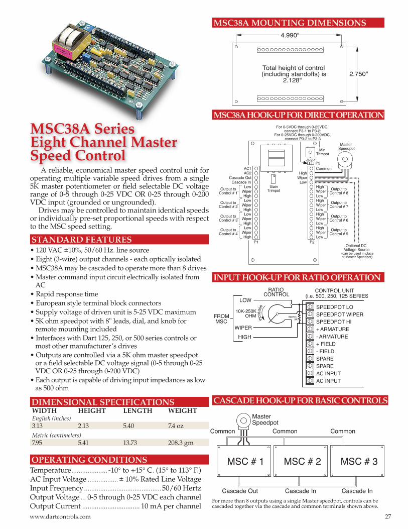
MSC38A MOUNTING DIMENSIONS
MSC38A HOOK-UP FOR DIRECT OPERATION
INPUT HOOK-UP FOR RATIO OPERATION
A reliable, economical master speed control unit for operating multiple variable speed drives from a single 5K master potentiometer or fi eld selectable DC voltage range of 0-5 through 0-25 VDC OR 0-25 through 0-200 VDC input (grounded or ungrounded).
Drives may be controlled to maintain identical speeds or individually pre-set proportional speeds with respect to the MSC speed setting.
STANDARD FEATURES• 120 VAC ±10%, 50/60 Hz. line source• Eight (3-wire) output channels - each optically isolated• MSC38A may be cascaded to operate more than 8 drives• Master command input circuit electrically isolated from AC• Rapid response time• European style terminal block connectors• Supply voltage of driven unit is 5-25 VDC maximum• 5K ohm speedpot with 8" leads, dial, and knob for remote mounting included• Interfaces with Dart 125, 250, or 500 series controls or most other manufacturer’s drives• Outputs are controlled via a 5K ohm master speedpot or a fi eld selectable DC voltage signal (0-5 through 0-25 VDC OR 0-25 through 0-200 VDC)• Each output is capable of driving input impedances as low as 500 ohm
DIMENSIONAL SPECIFICATIONS WIDTH HEIGHT LENGTH WEIGHTEnglish (inches) 3.13 2.13 5.40 7.4 ozMetric (centimeters)7.95 5.41 13.73 208.3 gm
OPERATING CONDITIONSTemperature .................... -10° to +45° C. (15° to 113° F.)AC Input Voltage .................± 10% Rated Line VoltageInput Frequency ...........................................50/60 HertzOutput Voltage ... 0-5 through 0-25 VDC each channelOutput Current ................................ 10 mA per channel
CASCADE HOOK-UP FOR BASIC CONTROLS
For more than 8 outputs using a single Master speedpot, controls can be cascaded together via the cascade and common terminals shown above.
Total height of control(including standoffs) is
2.128"2.750"
4.990"
CommonHighWiperLowHighWiperLowHighWiperLowHighWiperLowHighWiperLow
MinTrimpot
GainTrimpot
MasterSpeedpot
Output toControl # 8
Output toControl # 7
Output toControl # 6
Output toControl # 5
P2P1
AC1AC2
Cascade OutCascade In
LowWiperHighLow
WiperHighLow
WiperHighLow
WiperHigh
Output toControl # 1
Output toControl # 2
Output toControl # 3
Output toControl # 4
P3
For 0-5VDC through 0-25VDC,connect P3-1 to P3-2;
For 0-25VDC through 0-200VDC,connect P3-2 to P3-3
HighWiper
Low
Optional DCVoltage Source
(can be used in placeof Master Speedpot)
-3-2-1
A li bl i l t d t l
MSC38A SeriesEight Channel MasterSpeed Control
27www.dartcontrols.com
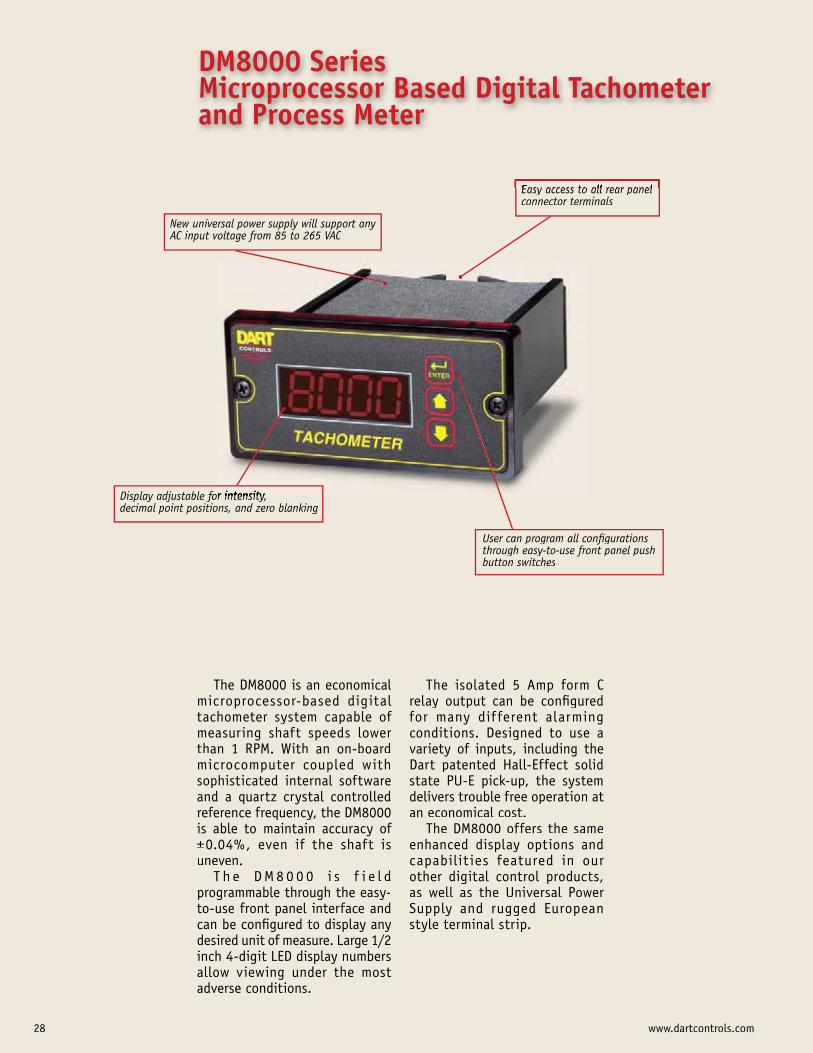
New universal power supply will support any AC input voltage from 85 to 265 VAC
Display adjustable for intensity, decimal point positions, and zero blanking
User can program all configurations through easy-to-use front panel push button switches
Easy access to all rear panel connector terminals
The DM8000 is an economical microprocessor-based digital tachometer system capable of measuring shaft speeds lower than 1 RPM. With an on-board microcomputer coupled withsophisticated internal software and a quartz crystal controlledreference frequency, the DM8000is able to maintain accuracy of ±uneven.
T h e D M 8 0 0 0 i s f i e l d programmable through the easy-to-use front panel interface and can be configured to display anydesired unit of measure. Large 1/2inch 4-digit LED display numbers allow viewing under the most adverse conditions.
The isolated 5 Amp form C relay output can be configured for many dif ferent alarming conditions. Designed to use a variety of inputs, including the Dart patented Hall-Effect solidstate PU-E pick-up, the system delivers trouble free operation at an economical cost.
The DM8000 offers the sameenhanced display options and capabilit ies featured in our other digital control products, as well as the Universal Power Supply and rugged European style terminal strip.
DM8000 Series Microprocessor Based Digital Tachometer and Process Meter
28 www.dartcontrols.com
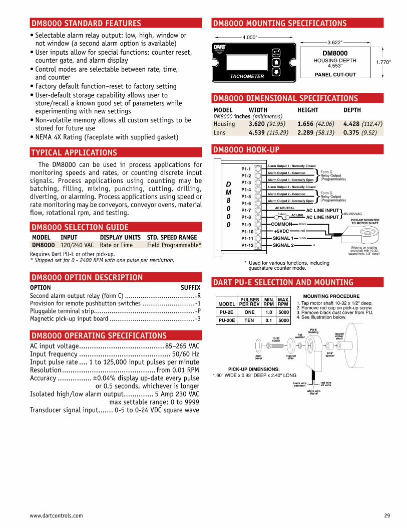
DM8000 MOUNTING SPECIFICATIONSDM8000 STANDARD FEATURES
not window (a second alarm option is available)
counter gate, and alarm display
and counter
store/recall a known good set of parameters while experimenting with new settings
stored for future use
TYPICAL APPLICATIONSThe DM8000 can be used in process applications for
monitoring speeds and rates, or counting discrete input signals. Process applications using counting may be batching, filling, mixing, punching, cutting, drilling, diverting, or alarming. Process applications using speed or rate monitoring may be conveyors, conveyor ovens, material flow, rotational rpm, and testing.
DM8000 SELECTION GUIDE
MODEL INPUT DISPLAY UNITS STD. SPEED RANGE DM8000 120/240 VAC Rate or Time Field Programmable*Requires Dart PU-E or other pick-up.* Shipped set for 0 - 2400 RPM with one pulse per revolution.
DM8000 OPTION DESCRIPTIONOPTION SUFFIXSecond alarm output relay (form C) ....................................-RProvision for remote pushbutton switches ...........................-1Pluggable terminal strip....................................................-PMagnetic pick-up input board ............................................-3
DM8000 OPERATING SPECIFICATIONSAC input voltage ........................................ 85–265 VACInput frequency ........................................... 50/60 HzInput pulse rate .... 1 to 125,000 input pulses per minuteResolution ............................................ from 0.01 RPMAccuracy ................ ± or 0.5 seconds, whichever is longerIsolated high/low alarm output .............. 5 Amp 230 VAC max settable range: 0 to 9999Transducer signal input ....... 0-5 to 0-24 VDC square wave
DART PU-E SELECTION AND MOUNTING
DM8000 DIMENSIONAL SPECIFICATIONS
MODEL WIDTH HEIGHT DEPTH DM8000 inches (millimeters)Housing 3.620 (91.95) 1.656 (42.06) 4.428 (112.47)Lens 4.539 (115.29) 2.289 (58.13) 0.375 (9.52)
DM8000 HOOK-UP
P1-1
P1-2
P1-3
P1-4
P1-5
P1-6
P1-7
P1-8
P1-9
P1-10
P1-11
P1-12
Alarm Output 1 - Normally Closed
Alarm Output 1 - Common
Alarm Output 1 - Normally Open
AC LINE INPUT
AC LINE INPUT}85-265VAC
}Form CRelay Output(Programmable)
Alarm Output 2 - Normally Closed
Alarm Output 2 - Common
Alarm Output 2 - Normally Open}Form CRelay Output(Programmable)
AC NEUTRAL
AC LINE5 Amp
PICK-UP MOUNTEDTO MOTOR SHAFTblack
white
red
COMMON
+5VDC
SIGNAL 1
(Mounts on rotatingend shaft with 10-32
tapped hole, 1/2" deep)
SIGNAL 2 *
* Used for various functions, including quadrature counter mode.
DM8000
black wirecommon
white wiresignal
red wire+5 volts
PULSES MIN. MAX.MODEL PER REV RPM RPM
PU-2E ONE 1.0 5000
PU-20E TEN 0.1 5000
MOUNTING PROCEDURE1.2.3.4.
Tap motor shaft 10-32 x 1/2" deep.Remove red cap on pick-up screw.Remove black dust cover from PU.See illustration below.
PICK-UP DIMENSIONS:1.60" WIDE x 0.93" DEEP x 2.40" LONG
dust cover
10-32 screw
magnet disc
flat washer
PU-E bearing
3/16" spacer
tapped motor shaft
TACHOMETER
ENTER
CONTROLS
4.000"
HOUSING DEPTH 4.553"
PANEL CUT-OUT
1.770"
DM8000
3.622"
29www.dartcontrols.com
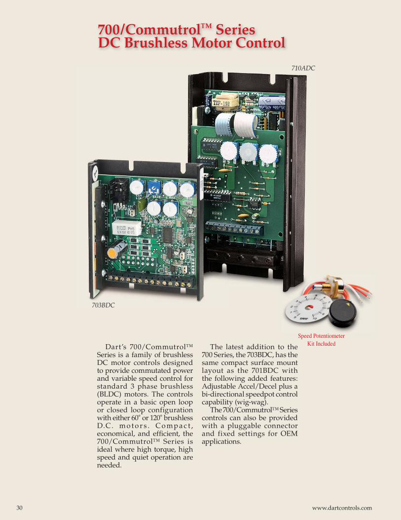
Dart’s 700/Commutrol™ Series is a family of brushless DC motor controls designed to provide commutated power and variable speed control for standard 3 phase brushless (BLDC) motors. The controls operate in a basic open loop or closed loop configuration with either 60˚ or 120˚ brushless D.C. m o t o r s . C o m p a c t , economical, and effi cient, the 700/Commutrol™ Series is ideal where high torque, high speed and quiet operation are needed.
The latest addition to the 700 Series, the 703BDC, has the same compact surface mount layout as the 701BDC with the following added features: Adjustable Accel/Decel plus a bi-directional speedpot control capability (wig-wag).
The 700/Commutrol™ Series controls can also be provided with a pluggable connector and fixed settings for OEM applications.
700/CommutrolTM Series DC Brushless Motor Control
703BDC
710ADC
Speed Potentiometer Kit Included
30 www.dartcontrols.com
5KΩ SPEEDPOT
F/R-B
+B
HI W LO
+5VGND
1S
5 AMPNORMAL
BLOWFUSE
ON/OFFSWITCH
white
P1
2S3S
orangered
-1 -2 -3 -4 -5 -6 -7 -8 -9 -10 -11-12 -13 -14
Φ3
Φ1
Φ2
BLDCMOTOR
-3-2-1
P5
-3-2-1
P2
-1-2-3
P3
P7
NOTE: P5 ONLY USED ON703BDC CONTROL
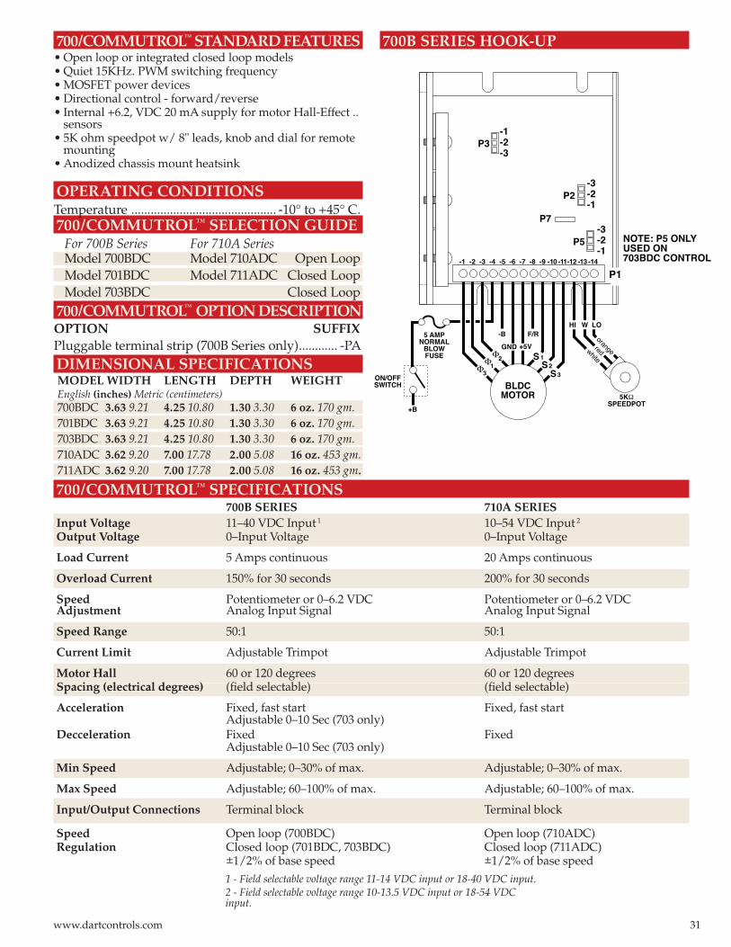
700/COMMUTROLTM
STANDARD FEATURES• Open loop or integrated closed loop models• Quiet 15KHz. PWM switching frequency• MOSFET power devices • Directional control - forward/reverse• Internal +6.2, VDC 20 mA supply for motor Hall-Effect .. sensors• 5K ohm speedpot w/ 8" leads, knob and dial for remote mounting• Anodized chassis mount heatsink
OPERATING CONDITIONSTemperature ............................................. -10° to +45° C.700/COMMUTROL™ SELECTION GUIDE For 700B Series For 710A Series Model 700BDC Model 710ADC Open Loop Model 701BDC Model 711ADC Closed Loop Model 703BDC Closed Loop700/COMMUTROLTM
OPTION DESCRIPTIONOPTION SUFFIXPluggable terminal strip (700B Series only) ............ -PADIMENSIONAL SPECIFICATIONSMODEL WIDTH LENGTH DEPTH WEIGHT English (inches) Metric (centimeters) 700BDC 3.63 9.21 4.25 10.80 1.30 3.30 6 oz. 170 gm.701BDC 3.63 9.21 4.25 10.80 1.30 3.30 6 oz. 170 gm.703BDC 3.63 9.21 4.25 10.80 1.30 3.30 6 oz. 170 gm.710ADC 3.62 9.20 7.00 17.78 2.00 5.08 16 oz. 453 gm.711ADC 3.62 9.20 7.00 17.78 2.00 5.08 16 oz. 453 gm.
700/COMMUTROL™ SPECIFICATIONS 700B SERIES 710A SERIESInput Voltage 11–40 VDC Input 1 10–54 VDC Input 2 Output Voltage 0–Input Voltage 0–Input Voltage
Load Current 5 Amps continuous 20 Amps continuous
Overload Current 150% for 30 seconds 200% for 30 seconds
Speed Potentiometer or 0–6.2 VDC Potentiometer or 0–6.2 VDCAdjustment Analog Input Signal Analog Input Signal
Speed Range 50:1 50:1
Current Limit Adjustable Trimpot Adjustable Trimpot
Motor Hall 60 or 120 degrees 60 or 120 degreesSpacing (electrical degrees) (fi eld selectable) (fi eld selectable)
Acceleration Fixed, fast start Fixed, fast start Adjustable 0–10 Sec (703 only)Decceleration Fixed Fixed Adjustable 0–10 Sec (703 only)
Min Speed Adjustable; 0–30% of max. Adjustable; 0–30% of max.
Max Speed Adjustable; 60–100% of max. Adjustable; 60–100% of max.
Input/Output Connections Terminal block Terminal block
Speed Open loop (700BDC) Open loop (710ADC)Regulation Closed loop (701BDC, 703BDC) Closed loop (711ADC) ±1/2% of base speed ±1/2% of base speed
1 - Field selectable voltage range 11-14 VDC input or 18-40 VDC input.2 - Field selectable voltage range 10-13.5 VDC input or 18-54 VDC input.
700B SERIES HOOK-UP
31www.dartcontrols.com
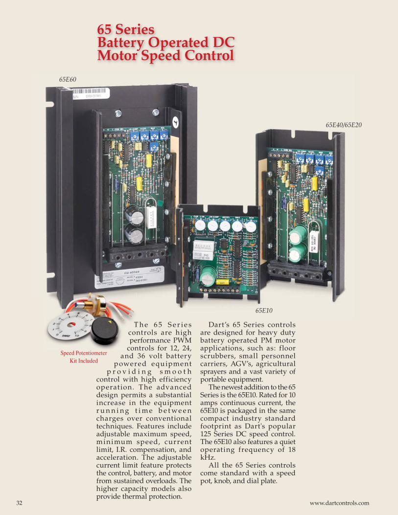
65 Series Battery Operated DC Motor Speed Control
T h e 6 5 S e r i e s controls are high performance PWM
controls for 12, 24, and 36 volt battery
powered equipment p r o v i d i n g s m o o t h
control with high efficiency operat ion. The advanced design permits a substantial increase in the equipment r u n n i n g t i m e b e t we e n charges over conventional techniques. Features include adjustable maximum speed, minimum speed, current limit, I.R. compensation, and acceleration. The adjustable current limit feature protects the control, battery, and motor from sustained overloads. The higher capacity models also provide thermal protection.
Dart’s 65 Series controls are designed for heavy duty battery operated PM motor applications, such as: floor scrubbers, small personnel carriers, AGV’s, agricultural sprayers and a vast variety of portable equipment.
The newest addition to the 65 Series is the 65E10. Rated for 10 amps continuous current, the 65E10 is packaged in the same compact industry standard footprint as Dart's popular 125 Series DC speed control. The 65E10 also features a quiet operating frequency of 18 kHz.
All the 65 Series controls come standard with a speed pot, knob, and dial plate.
65E60
65E40/65E20
65E10
Tconpe
conSpeed Potentiometer
Kit Included
32 www.dartcontrols.com
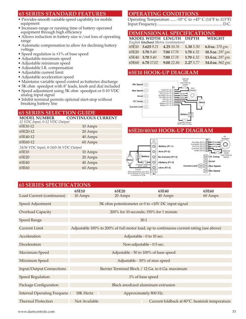
65 SERIES SPECIFICATIONS 65E10 65E20 65E40 65E60Load Current (continuous) 10 Amps 20 Amps 40 Amps 60 Amps
Speed Adjustment 5K ohm potentiometer or 0 to +10V DC input signal
Overload Capacity 200% for 10 seconds; 150% for 1 minute
Speed Range 30:1
Current Limit Adjustable 100% to 200% of full motor load, up to continuous current rating (see above)
Acceleration Adjustable - 0 to 10 sec.
Deceleration Non-adjustable - 0.5 sec.
Maximum Speed Adjustable - 50 to 100% of base speed
Minimum Speed Adjustable - 30% of max speed
Input/Output Connections Barrier Terminal Block / 12 Ga. to 6 Ga. maximum
Speed Regulation 1% of base speed
Package Confi guration Black anodized aluminum extrusion
Internal Operating Frequency 18K Hertz Approximately 800 Hz.
Thermal Protection Not Available Current foldback at 80°C. heatsink temperature
65 SERIES STANDARD FEATURES • Provides smooth variable speed capability for mobile equipment• Increases range or running time of battery operated equipment through high effi ciency• Allows reduction in battery size w/out loss of operating range• Automatic compensation to allow for declining battery voltage• Speed regulation is ±1% of base speed• Adjustable maximum speed• Adjustable minimum speed• Adjustable I.R. compensation• Adjustable current limit• Adjustable acceleration speed• Maintains variable speed control as batteries discharge• 5K ohm speedpot with 8" leads, knob and dial included• Speed adjustment using 5K ohm speedpot or 0-10 VDC analog input signal• Inhibit terminal permits optional start-stop without breaking battery line
65 SERIES SELECTION GUIDE MODEL NUMBER CONTINUOUS CURRENT 12 VDC Input, 0-12 VDC Output 65E10-12 10 Amps 65E20-12 20 Amps 65E40-12 40 Amps 65E60-12 60 Amps 24/36 VDC Input, 0-24/0-36 VDC Output 65E10 10 Amps 65E20 20 Amps 65E40 40 Amps 65E60 60 Amps
OPERATING CONDITIONSOperating Temperature ...... -10° C to +45° C (14°F to 113°F)Input Frequency .................................................................. D.C.
DIMENSIONAL SPECIFICATIONS MODEL WIDTH LENGTH DEPTH WEIGHT English (inches) Metric (centimeters) 65E10 3.625 9.21 4.25 10.76 1.30 3.30 6.0 oz. 170 gm. 65E20 3.70 9.40 7.00 17.78 1.70 4.32 10.5 oz. 297 gm. 65E40 3.70 9.40 7.00 17.78 1.70 4.32 13.4 oz. 297 gm. 65E60 6.70 17.02 9.00 22.86 2.27 5.77 34.0 oz. 962 gm.
65E10 HOOK-UP DIAGRAM
Max Speed
Accel
Min Speed
Current Limit
I.R. Comp.
Inhibit (P1-9)Common (P1-8)Pot Low (P1-7)
Pot Wiper (P1-6)Pot High (P1-5)
-Arm (P1-4)+Arm (P1-3)
+Battery (P1-2)-Battery (P1-1)
P1 5KWSpeedpot
WhiteRed
Orange
OptionalInhibit
(see hook-upbelow)
Battery
Motor
Customer suppliedSPST switch or relay
65E20/40/60 HOOK-UP DIAGRAM
+
-
+
-
Battery
Caution:Motor and battery wire mustbe a minimum of 12 ga. and
a maximum of 6 ga.
Pot High (P2-1)Pot Wiper (P2-2)
Pot Low (P2-3)Common (P2-4)
Inhibit (P2-5)
+Arm (P1-5)
+Battery (P1-4)
No Connect (P1-3)
-Arm (P1-2)
-Battery (P1-1)
5K Speedpot
OrangeRed
White
Current Limit Max Speed
Accel
I.R. Comp.
Min Speed
Motor
OptionalInhibit
(see hook-upbelow)
Customer suppliedSPST switch
++
P1
P2
33www.dartcontrols.com
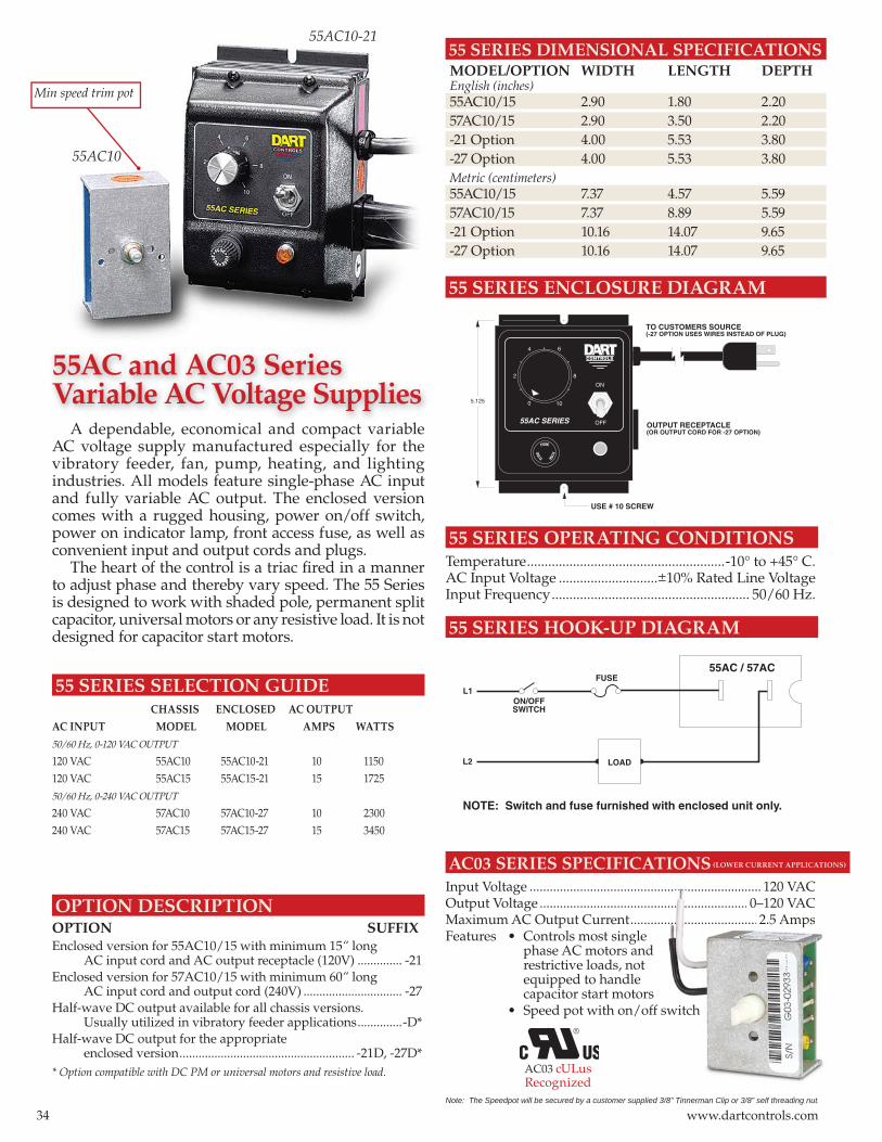
55 SERIES DIMENSIONAL SPECIFICATIONS MODEL/OPTION WIDTH LENGTH DEPTH English (inches) 55AC10/15 2.90 1.80 2.20 57AC10/15 2.90 3.50 2.20 -21 Option 4.00 5.53 3.80 -27 Option 4.00 5.53 3.80 Metric (centimeters) 55AC10/15 7.37 4.57 5.59 57AC10/15 7.37 8.89 5.59 -21 Option 10.16 14.07 9.65 -27 Option 10.16 14.07 9.65
55 SERIES ENCLOSURE DIAGRAM
55 SERIES OPERATING CONDITIONSTemperature ........................................................-10° to +45° C.AC Input Voltage ............................±10% Rated Line VoltageInput Frequency ........................................................ 50/60 Hz.
55 SERIES HOOK-UP DIAGRAM
A dependable, economical and compact variable AC voltage supply manufactured especially for the vibratory feeder, fan, pump, heating, and lighting industries. All models feature single-phase AC input and fully variable AC output. The enclosed version comes with a rugged housing, power on/off switch, power on indicator lamp, front access fuse, as well as convenient input and output cords and plugs.
The heart of the control is a triac fi red in a manner to adjust phase and thereby vary speed. The 55 Series is designed to work with shaded pole, permanent split capacitor, universal motors or any resistive load. It is not designed for capacitor start motors.
55 SERIES SELECTION GUIDE CHASSIS ENCLOSED AC OUTPUT
AC INPUT MODEL MODEL AMPS WATTS
50/60 Hz, 0-120 VAC OUTPUT 120 VAC 55AC10 55AC10-21 10 1150120 VAC 55AC15 55AC15-21 15 172550/60 Hz, 0-240 VAC OUTPUT 240 VAC 57AC10 57AC10-27 10 2300240 VAC 57AC15 57AC15-27 15 3450
OPTION DESCRIPTIONOPTION SUFFIXEnclosed version for 55AC10/15 with minimum 15“ long AC input cord and AC output receptacle (120V) .............. -21Enclosed version for 57AC10/15 with minimum 60“ long AC input cord and output cord (240V) ............................... -27Half-wave DC output available for all chassis versions. Usually utilized in vibratory feeder applications ..............-D*Half-wave DC output for the appropriate enclosed version ....................................................... -21D, -27D** Option compatible with DC PM or universal motors and resistive load.
55AC10
55AC10-21
8
ON
OFF
0 10
2
4 6
55AC SERIES
FUSE
FUSE
FUSE
TO CUSTOMERS SOURCE(-27 OPTION USES WIRES INSTEAD OF PLUG)
OUTPUT RECEPTACLE(OR OUTPUT CORD FOR -27 OPTION)
USE # 10 SCREW
5.125
��������
LOAD
FUSE
ON/OFFSWITCH
L1
L2
55AC / 57AC
NOTE: Switch and fuse furnished with enclosed unit only.
Min speed trim pot
55AC and AC03 SeriesVariable AC Voltage Supplies
AC03 SERIES SPECIFICATIONS (LOWER CURRENT APPLICATIONS)
Input Voltage ..................................................................... 120 VACOutput Voltage .............................................................. 0–120 VACMaximum AC Output Current ......................................2.5 AmpsFeatures • Controls most single phase AC motors and restrictive loads, not equipped to handle capacitor start motors • Speed pot with on/off switch
Note: The Speedpot will be secured by a customer supplied 3/8” Tinnerman Clip or 3/8” self threading nut.
..... ......................... ...................... 120 VAC
................. ................... 0–120 VAC
...................... ........ .....................2.5 Amps
switch
/8” Tinnerman Clip or 3/8” self threading nut.
AC03 cULus Recognized
34 www.dartcontrols.com
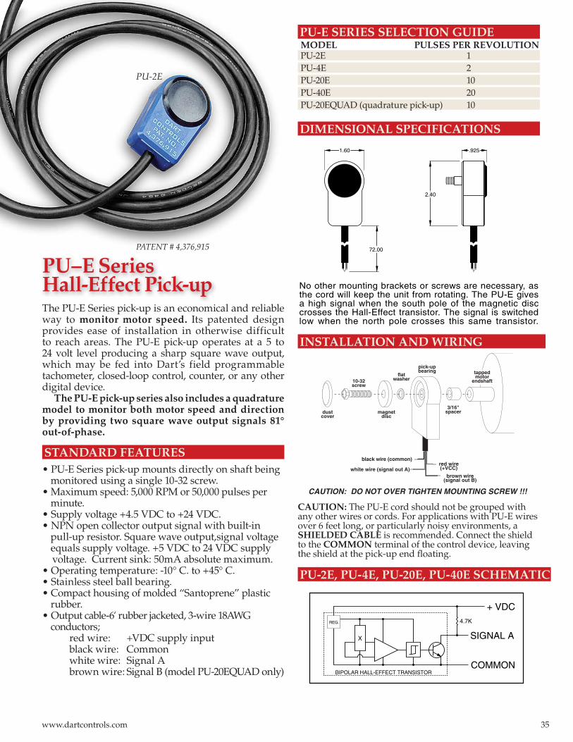
dustcover
10-32screw
magnetdisc
flatwasher
pick-upbearing
3/16"spacer
black wire (common)
white wire (signal out A)red wire(+VCC)
tappedmotor
endshaft
CAUTION: DO NOT OVER TIGHTEN MOUNTING SCREW !!!
brown wire(signal out B)
PU-E SERIES SELECTION GUIDE MODEL PULSES PER REVOLUTION PU-2E 1 PU-4E 2 PU-20E 10 PU-40E 20 PU-20EQUAD (quadrature pick-up) 10
DIMENSIONAL SPECIFICATIONS
The PU-E Series pick-up is an economical and reliable way to monitor motor speed. Its patented design provides ease of installation in otherwise difficult to reach areas. The PU-E pick-up operates at a 5 to 24 volt level producing a sharp square wave output, which may be fed into Dart’s field programmable tachometer, closed-loop control, counter, or any other digital device.
The PU-E pick-up series also includes a quadrature model to monitor both motor speed and direction by providing two square wave output signals 81° out-of-phase.
STANDARD FEATURES• PU-E Series pick-up mounts directly on shaft being monitored using a single 10-32 screw.• Maximum speed: 5,000 RPM or 50,000 pulses per minute.• Supply voltage +4.5 VDC to +24 VDC.• NPN open collector output signal with built-in pull-up resistor. Square wave output,signal voltage equals supply voltage. +5 VDC to 24 VDC supply voltage. Current sink: 50mA absolute maximum.• Operating temperature: -10° C. to +45° C.• Stainless steel ball bearing.• Compact housing of molded “Santoprene” plastic rubber.• Output cable-6‘ rubber jacketed, 3-wire 18AWG conductors; red wire: +VDC supply input black wire: Common white wire: Signal A brown wire: Signal B (model PU-20EQUAD only)
PU-2E, PU-4E, PU-20E, PU-40E SCHEMATIC
PU-2E
PATENT # 4,376,915
CAUTION: The PU-E cord should not be grouped with any other wires or cords. For applications with PU-E wires over 6 feet long, or particularly noisy environments, a SHIELDED CABLE is recommended. Connect the shield to the COMMON terminal of the control device, leaving the shield at the pick-up end fl oating.
INSTALLATION AND WIRING
72.00
2.40
1.60 .925
No other mounting brackets or screws are necessary, asthe cord will keep the unit from rotating. The PU-E givesa high signal when the south pole of the magnetic disccrosses the Hall-Effect transistor. The signal is switchedlow when the north pole crosses this same transistor.
BIPOLAR HALL-EFFECT TRANSISTOR
X
REG.
SIGNAL A
+ VDC
COMMON
4.7K
PU–E SeriesHall-Effect Pick-up
35www.dartcontrols.com
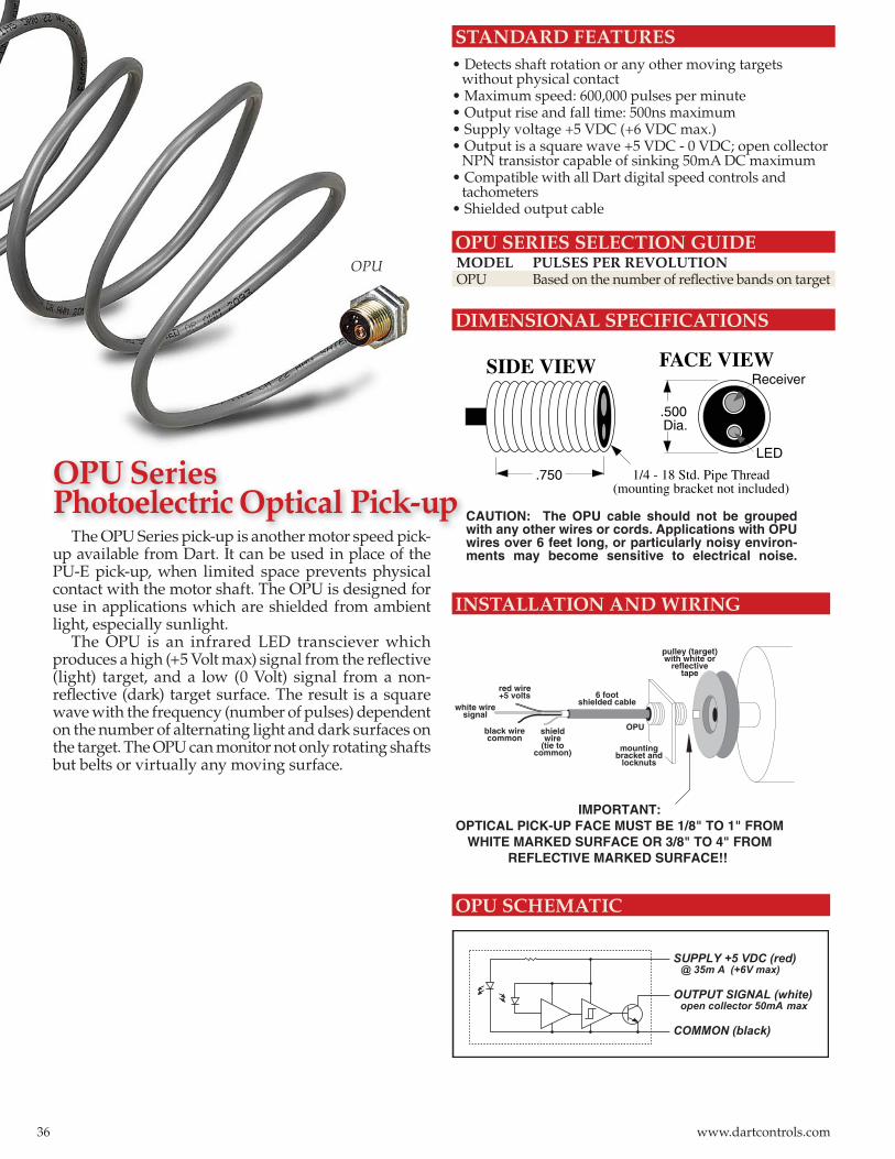
STANDARD FEATURES• Detects shaft rotation or any other moving targets without physical contact• Maximum speed: 600,000 pulses per minute• Output rise and fall time: 500ns maximum• Supply voltage +5 VDC (+6 VDC max.)• Output is a square wave +5 VDC - 0 VDC; open collector NPN transistor capable of sinking 50mA DC maximum• Compatible with all Dart digital speed controls and tachometers• Shielded output cable
OPU SERIES SELECTION GUIDE MODEL PULSES PER REVOLUTION OPU Based on the number of refl ective bands on target
DIMENSIONAL SPECIFICATIONS
The OPU Series pick-up is another motor speed pick-up available from Dart. It can be used in place of the PU-E pick-up, when limited space prevents physical contact with the motor shaft. The OPU is designed for use in applications which are shielded from ambient light, especially sunlight.
The OPU is an infrared LED transciever which produces a high (+5 Volt max) signal from the refl ective (light) target, and a low (0 Volt) signal from a non-refl ective (dark) target surface. The result is a square wave with the frequency (number of pulses) dependent on the number of alternating light and dark surfaces on the target. The OPU can monitor not only rotating shafts but belts or virtually any moving surface.
OPU SCHEMATIC
INSTALLATION AND WIRING
OPU
CAUTION: The OPU cable should not be grouped with any other wires or cords. Applications with OPU wires over 6 feet long, or particularly noisy environ-ments may become sensitive to electrical noise.
FACE VIEWSIDE VIEW
.500Dia.
.750 1/4 - 18 Std. Pipe Thread(mounting bracket not included)
Receiver
LED
OUTPUT SIGNAL (white)
SUPPLY +5 VDC (red)
COMMON (black)
open collector 50mA max
@ 35m A (+6V max)
IMPORTANT:OPTICAL PICK-UP FACE MUST BE 1/8" TO 1" FROM
WHITE MARKED SURFACE OR 3/8" TO 4" FROMREFLECTIVE MARKED SURFACE!!
black wirecommon
white wiresignal
red wire+5 volts
shield wire
(tie to common)
6 foot shielded cable
pulley (target) with white or
reflective tape
mountingbracket and
locknuts
OPU
h k h d k
OPU SeriesPhotoelectric Optical Pick-up
36 www.dartcontrols.com
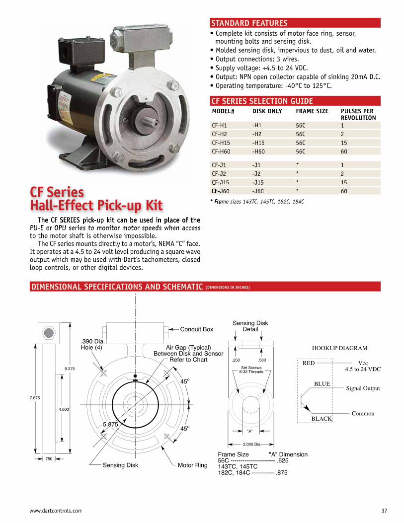
45o
Air Gap (Typical)Between Disk and Sensor
Refer to Chart
Sensing Disk Motor Ring
.390 Dia.Hole (4)
45o
5.875
Conduit Box
Set Screws8-32 Threads
"A"
2.000 Dia.
.250 .500
Sensing DiskDetail
4.000
7.875
9.375
.750Frame Size "A" Dimension56C ---------------------- .625143TC, 145TC182C, 184C ----------- .875
Vcc4.5 to 24 VDC
RED
Signal Output
Common
BLUE
BLACK
HOOKUP DIAGRAM
STANDARD FEATURES
mounting bolts and sensing disk.
Output: NPN open collector capable of sinking 20mA D.C.
CF SERIES SELECTION GUIDEMODEL# DISK OK NLY FRAME SIZE PULSES PER
REVOLUTIONCF-H1 -H1 56C 1CF-H2 -H2 56C 2CF-H15 -H15 56C 15CF-H60 -H60 56C 60
CF-J1 -J1 * 1CF-J2 -J2 * 2CF-J15 -J15 * 15
J60 -J60 * 60
ame sizes 143TC, 145TC, 182C, 184C
PU-E or OPU series to monitor motor speeds when access to the motor shaft is otherwise impossible.
The CF series mounts directly to a motor’s, NEMA “C” face. It operates at a 4.5 to 24 volt level producing a square wave output which may be used with Dart’s tachometers, closedloop controls, or other digital devices.
DIMENSIONAL SPECIFICATIONS AND SCHEMATIC (DIMENSIONS IN INCHES)
CF Series Hall-Effect Pick-up Kit
37www.dartcontrols.com
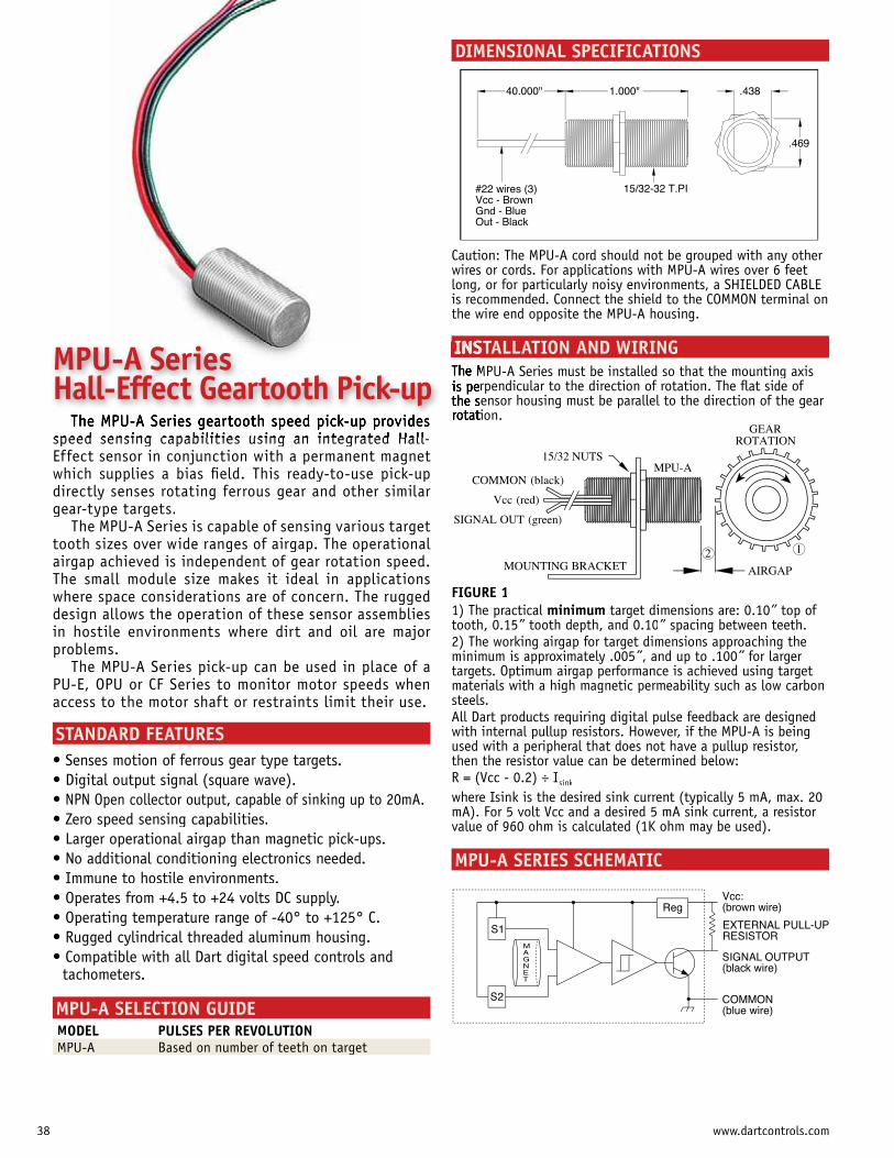
GEARROTATION
COMMON (black)
Vcc (red)
SIGNAL OUT (green)
MPU-A15/32 NUTS
MOUNTING BRACKET AIRGAP
2 1
.469
1.000"40.000" .438
15/32-32 T.PI#22 wires (3)Vcc - BrownGnd - BlueOut - Black
DIMENSIONAL SPECIFICATIONS
speed sensing capabilities using an integrated Hall-Effect sensor in conjunction with a permanent magnetwhich supplies a bias field. This ready-to-use pick-updirectly senses rotating ferrous gear and other similar gear-type targets.
The MPU-A Series is capable of sensing various target tooth sizes over wide ranges of airgap. The operational airgap achieved is independent of gear rotation speed. The small module size makes it ideal in applications where space considerations are of concern. The ruggeddesign allows the operation of these sensor assemblies in hostile environments where dirt and oil are major problems.
The MPU-A Series pick-up can be used in place of aPU-E, OPU or CF Series to monitor motor speeds whenaccess to the motor shaft or restraints limit their use.
STANDARD FEATURES
NPN Open collector output, capable of sinking up to 20mA.
tachometers.
MPU-A SELECTION GUIDEMODEL PULSES PER REVOLUTIONMPU-A gBased on number of teeth on target
FIGURE 11) The practical minimum target dimensions are: 0.10” top of ”tooth, 0.15” tooth depth, and 0.10” ” spacing between teeth.”2) The working airgap for target dimensions approaching theminimum is approximately .005”, and up to .100” for larger ”targets. Optimum airgap performance is achieved using target materials with a high magnetic permeability such as low carbonsteels. All Dart products requiring digital pulse feedback are designed with internal pullup resistors. However, if the MPU-A is beingused with a peripheral that does not have a pullup resistor, then the resistor value can be determined below:R = (Vcc - 0.2) ÷ Isink
where Isink is the desired sink current (typically 5 mA, max. 20mA). For 5 volt Vcc and a desired 5 mA sink current, a resistor value of 960 ohm is calculated (1K ohm may be used).
MPU-A SERIES SCHEMATIC
Caution: The MPU-A cord should not be grouped with any other wires or cords. For applications with MPU-A wires over 6 feetlong, or for particularly noisy environments, a SHIELDED CABLEis recommended. Connect the shield to the COMMON terminal onthe wire end opposite the MPU-A housing.
INSTALLATION AND WIRINGMPU-A Series must be installed so that the mounting axisrpendicular to the direction of rotation. The flat side of ensor housing must be parallel to the direction of the gear ion.
SIGNAL OUTPUT(black wire)
Vcc:(brown wire)
COMMON(blue wire)
MAGNET
S1
S2
Reg
EXTERNAL PULL-UPRESISTOR
MPU-A Series Hall-Effect Geartooth Pick-up
38 www.dartcontrols.com
DEFINITION OF TERMS1. ADJUSTABLE CURRENT LIMITING (TORQUE LIMITING) This feature permits the operator to adjust the maximum current the motor will draw. This in effect limits the maximum torque the motor will produce.2. ADJUSTABLE LINEAR ACCELERATION Allows the operator to adjust the amount of time it takes the motor to come up from stop to the maximum speed setting. This available in time spans up to 12 seconds (model dependent), with longer times available as special items.3. ADJUSTABLE MINIMUM AND MAXIMUM SPEED This feature allows the operator to set the minimum and maximum speeds that the motor is to operate. The main speed dial then adjusts the speed between this range. 4. BASIC TYPE OF LOAD The three basic types of loads, (constant torque, variable torque, and constant horsepower) can be accommodated with Dart controllers when properly selected.5. CHASSIS MOUNT (LESS ENCLOSURE)Open construction for mounting in the customers existing enclosures or control consoles.6. COGGINGSpeed change as a result of armature coils entering and leaving magnetic fields. 7. CONSTANT HORSEPOWER This type of load requires constant horsepower throughout the speed range and the torque increases as the speed decreases. For all constant
lowest operating speed determines the horsepower of the drive. 8. CONSTANT TORQUE By far the most common of loads. Torque remains constant throughout the speed range while the horsepower required decreases in direct proportion from maximum to minimum speed. In all constant torque applications, the drive is selected based on the maximum horsepower required by the driven equipment at its maximum speed.9. CONTROL BY REMOTE SIGNAL Remote signal controls take the form of voltage or current signals in
controls are available both electrically isolated and non-isolated. It is important therefore to indicate if the remote signal is not electrically isolated from the power source (grounded). 10. CONTROLLED (TIMED) ACCELERATION This feature will accelerate the motor to the set speed in a given length of time.11. DUTY-CYCLEThe relation between the operating time and the rest time of a motor. A motor which continues to operate after it has reached its normal operating (steady) temperature is operating under continuous duty conditions. One which never reaches a steady temperature but is permitted to cool between operations is operating under intermittent duty conditions. 12. DYNAMIC BRAKING A way of stopping a brush-type motor by first disconnecting the power source. The rotating motor then becomes a generator which is connected to a resistor. The energy of rotation is then dissipated as heat in the resistors. 13. HORSEPOWER OR TORQUE REQUIRED If the horsepower or torque for a given application is not known, it can usually be calculated using of the following methods:HORSEPOWER= Force (lbs) x Feet per minute 33,000HORSEPOWER= Torque (in-lbs) x RPM 63,025HORSEPOWER= Torque (ft-lbs) x RPM 5,252
63,025 x HP RPM
5,252 x HP RPMFEET/MINUTE = 262 x Dia. of wheel (inches) x RPM14. IR COMPENSATION This function compensates for the resistance change in the armature due to load changes and also increases the speed regulation range.
15. JOGGING This feature provides a means of inching the motor using a single button. The jog feature is available only when a separate remote station is used (i.e. Start-Stop). A run jog selector is provided along with the jog button itself. 16. LINE VOLTAGE COMPENSATION Holds the motor speed constant when the line voltage fluctuates over a range of ±17. MULTI-MOTOR CONTROL OR MASTER OVERRIDE This is accomplished by one of two ways, namely: A) A master control which controls each individual control and its associated motor. Using this method the master control sets the maximum speed that can be set on the individual unit, maintaining the ratio. B) Connecting more than one motor to an individual control. Satisfactory results are limited to specific applications using this arrangement. Consult the applications department before specifying this system. 18. PLUG REVERSAL A method of changing the rotation of a motor by reversing connection polarity as the motor runs. This is not recommended for DC motors – it can damage the control and motor and reduce their life. 19. POTENTIOMETER SPEED INDICATOR This feature provides a means of speed indication by monitoring the voltage on the speed set control. This meter is accurate to the degree
is used where a meter is desired. 20. PRE-SET SPEED A selected speed may be set when the control is not in operation. The motor will then accelerate to the pre-set speed when the switch is turned on. 21. PUSHBUTTON SPEED CONTROL Permits the selection of speed settings via pushbuttons. 22. REVERSING, ELECTRICAL (AUTOMATIC) Utilizes relays and/or solid state circuitry to automatically provide dynamic
speed. Direction is controlled with a SPDT switch, relay contacts (dry contact switching), or NPN open collector.23. REVERSING, MANUAL The manual reverse incorporates a switch to reverse the polarity of the armature leads. The switch is constructed so that the leads cannot be reversed without going through a neutral or brake position. 24. SPEED ADJUSTMENT POTENTIOMETER The standard speed control is a single turn, 300° potentiometer is available. 25. SPEED RANGE The speed range is defined as the ratio of minimum to maximum speed where the speed regulation published is obtained. The motor speed is always adjustable to zero. 26. SPEED REGULATION Defined as the change in motor RPM from NO LOAD TO FULL LOAD, and expressed as a percentage of base speed. For close regulation a tachometer generator feedback system or digital closed loop control is suggested.27. TACHOMETER FEEDBACK This feature includes the tachometer mounted on the opposite end of the motor. Extremely close regulation is available with tachometer feedback.
28. TACHOMETER FOLLOWER Permits the speed control to be controlled by a remote tachometer. The speed control maximum trim pot then adjusts the maximum speed at which the motor will run. Note: The tachometer (customer mounted) must run at the speed the motor to be controlled runs.29. TACHOMETER SPEED REGULATION This feature normally used in conjunction with Tachometer Feedback (item 27) includes the tachometer mounted on the end shaft of the motor and
The standard meter scale is 3.5 inches. 30. VARIABLE TORQUE AND HORSEPOWER Although encountered considerably less often than constant torque, this type load should be recognized as having an increase in horsepower that varies as the square or cube of the increase in speed. With this type of load the horsepower and torque required increases at a greater rate than the increases in driver speed. As with the constant torque load drive the variable torque and the horsepower load drive should be reflected for the maximum horsepower required by the driven equipment at its maximum speed.
39www.dartcontrols.com
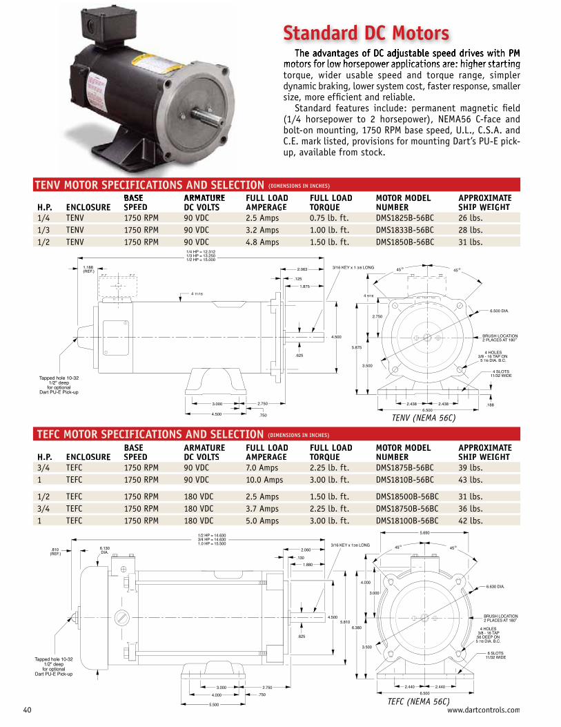
o
Tapped hole 10-32 1/2" deep
for optional Dart PU-E Pick-up
4.500
3.000 2.750
.750
.625
4.500
1.875
2.063
.125
1/4 HP = 12.312 1/3 HP = 13.250 1/2 HP = 15.000
4 11/16
1.188 (REF.)
5.875
4 9/16
2.750
3.500
2.438 2.438
6.500.188
4 SLOTS11/32 WIDE
BRUSH LOCATION2 PLACES AT 180
4 HOLES3/8 - 16 TAP ON 5 7/8 DIA. B.C.
6.500 DIA.
o45 o453/16 KEY x 1 3/8 LONG
TENV MOTOR SPECIFICATIONS AND SELECTION (DIMENSIONS IN INCHES)
BASE ARMATURE FULL LOAD FULL LOAD MOTOR MODEL APPROXIMATEH.P. ENCLOSURE SPEED DC VOLTS AMPERAGE TORQUE NUMBER SHIP WEIGHT/ p1/4 TENV 1750 RPM 90 VDC 2.5 Amps 0.75 lb. ft. DMS1825B-56BC 26 lbs./ p1/3 TENV 1750 RPM 90 VDC 3.2 Amps 1.00 lb. ft. DMS1833B-56BC 28 lbs./ p1/2 TENV 1750 RPM 90 VDC 4.8 Amps 1.50 lb. ft. DMS1850B-56BC 31 lbs.
TEFC MOTOR SPECIFICATIONS AND SELECTION (DIMENSIONS IN INCHES)
BASE ARMATURE FULL LOAD FULL LOAD MOTOR MODEL APPROXIMATEH.P. ENCLOSURE SPEED DC VOLTS AMPERAGE TORQUE NUMBER SHIP WEIGHT/ p3/4 TEFC 1750 RPM 90 VDC 7.0 Amps 2.25 lb. ft. DMS1875B-56BC 39 lbs.
p1 TEFC 1750 RPM 90 VDC 10.0 Amps 3.00 lb. ft. DMS1810B-56BC 43 lbs.
/ p1/2 TEFC 1750 RPM 180 VDC 2.5 Amps 1.50 lb. ft. DMS18500B-56BC 31 lbs./ p3/4 TEFC 1750 RPM 180 VDC 3.7 Amps 2.25 lb. ft. DMS18750B-56BC 36 lbs.
p1 TEFC 1750 RPM 180 VDC 5.0 Amps 3.00 lb. ft. DMS18100B-56BC 42 lbs.
TENV (NEMA 56C)TENV (NEMA 56C)
o
Tapped hole 10-32 1/2" deep
for optional Dart PU-E Pick-up
.625
4.500
6.380
3.500
2.440 2.440
6.500
6 SLOTS11/32 WIDE
BRUSH LOCATION2 PLACES AT 180
4 HOLES 3/8 - 16 TAP .56 DEEP ON 5 7/8 DIA. B.C.
6.630 DIA.
o45 o453/16 KEY x 13/8 LONG
5.810
2.750
.750
3.000
4.000
5.500
4.000
3.000
5.690
1.880
2.060
.130
1/2 HP = 14.630 3/4 HP = 14.630 1.0 HP = 15.500
.810(REF.)
6.130 DIA.
TEFC (NEMA 56C)
motors for low horsepower applications are: higher startingtorque, wider usable speed and torque range, simpler dynamic braking, lower system cost, faster response, smaller size, more efficient and reliable.
Standard features include: permanent magnetic field(1/4 horsepower to 2 horsepower), NEMA56 C-face andbolt-on mounting, 1750 RPM base speed, U.L., C.S.A. and C.E. mark listed, provisions for mounting Dart’s PU-E pick-up, available from stock.
Standard DC Motors
40 www.dartcontrols.com)
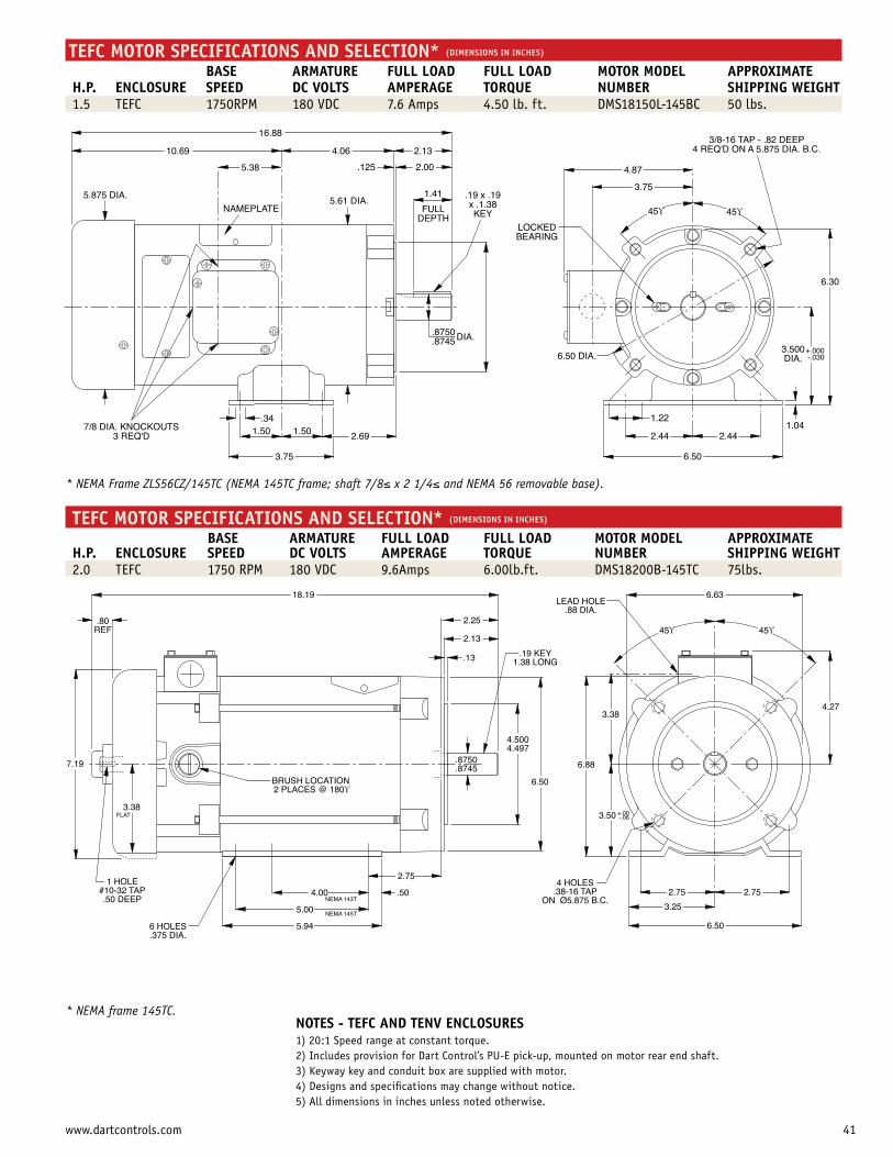
TEFC MOTOR SPECIFICATIONS AND SELECTION* (DIMENSIONS IN INCHES)
BASE ARMATURE FULL LOAD FULL LOAD MOTOR MODEL APPROXIMATEH.P. ENCLOSURE SPEED DC VOLTS AMPERAGE TORQUE NUMBER SHIPPING WEIGHT1.5 TEFC 1750RPM 180 VDC 7.6 Amps 4.50 lb. ft. DMS18150L-145BC 50 lbs.
* NEMA Frame ZLS56CZ/145TC (NEMA 145TC frame; shaft 7/8≤ x 2 1/4≤ and NEMA 56 removable base).
TEFC MOTOR SPECIFICATIONS AND SELECTION* (DIMENSIONS IN INCHES)
BASE ARMATURE FULL LOAD FULL LOAD MOTOR MODEL APPROXIMATEH.P. ENCLOSURE SPEED DC VOLTS AMPERAGE TORQUE NUMBER SHIPPING WEIGHT2.0 TEFC 1750 RPM 180 VDC 9.6Amps 6.00lb.ft. DMS18200B-145TC 75lbs.
* NEMA frame 145TC.
3/8-16 TAP - .82 DEEP4 REQ'D ON A 5.875 DIA. B.C.
4.87
3.75
45ϒ 45ϒ
6.50 DIA.
LOCKEDBEARING
.19 x .19x .1.38KEY
2.44 2.44
6.50
1.221.04
6.30
3.500DIA.
+.000-.030
3.75
2.691.501.50.34
7/8 DIA. KNOCKOUTS3 REQ'D
5.875 DIA.
10.69
.8750
.8745 DIA.
5.61 DIA.
5.38
2.13
2.00
4.06
.125
16.88
NAMEPLATE
1.41
FULLDEPTH
18.19
.80REF
7.19
3.38FLAT
1 HOLE#10-32 TAP.50 DEEP
6 HOLES.375 DIA.
4.00
BRUSH LOCATION2 PLACES @ 180ϒ
4.5004.497
5.00
5.94
.50
2.75
.8750
.8745
6.50
NEMA 145T
NEMA 143T
2.13
2.25
.13 .19 KEY1.38 LONG
6.88
3.38
3.50 +.00-.06
4 HOLES.38-16 TAP
ON Ø5.875 B.C.
6.63LEAD HOLE
.88 DIA.
45ϒ 45ϒ
4.27
2.752.75
3.25
6.50
NOTES - TEFC AND TENV ENCLOSURES 1) 20:1 Speed range at constant torque.2) Includes provision for Dart Control’s PU-E pick-up, mounted on motor rear end shaft.3) Keyway key and conduit box are supplied with motor.4) Designs and specifications may change without notice.5) All dimensions in inches unless noted otherwise.
41www.dartcontrols.com
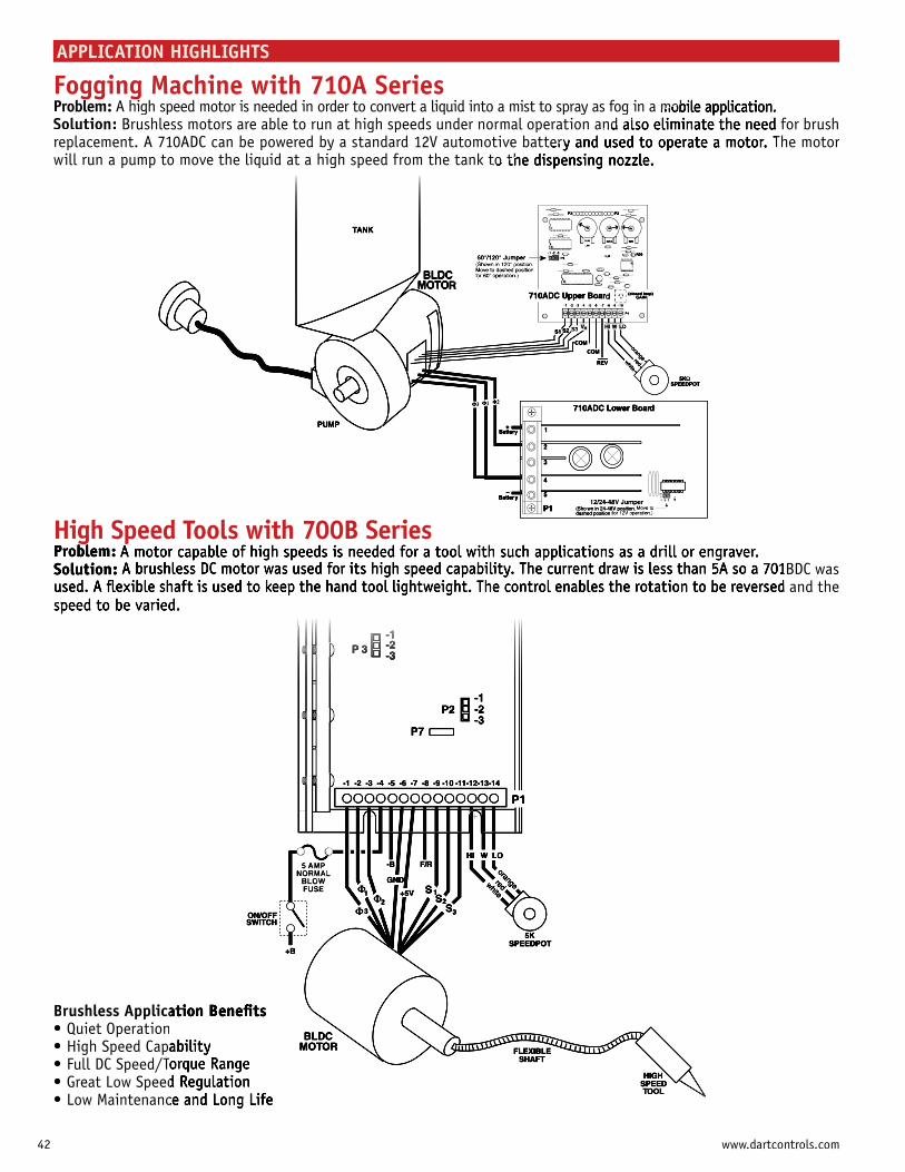
APPLICATION HIGHLIGHTS
High Speed Tools with 700B Series1BDC wasd and the
Fogging Machine with 710A SeriesProblem: A high speed motor is needed in order to convert a liquid into a mist to spray as fog in a mobile application.Solution: Brushless motors are able to run at high speeds under normal operation and also eliminate the need for brushreplacement. A 710ADC can be powered by a standard 12V automotive battery and used to operate a motor. The motor will run a pump to move the liquid at a high speed from the tank to the
Brushless Applica
42 www.dartcontrols.com

TachItem
ValuPageENTER
DIGITAL
AlarmRev FwdNeg
AC Drive
H
WL
Alarm Output
DP4
TachItem
ValuPageENTER
DIGITAL POT
AlarmRev FwdNeg
Regenerative DC Drive orother Reversing Drives
+10H
WL -10
Alarm Output
DP4
Digital Potentiometer (DP4)/ AC Drive Combination
Using the DP4 with an AC drive adds flexibility and capability to the system. The DP4 has a NEMA 4X rated faceplate and comes complete with a gasket kit allowing it to be mounted in a NEMA 4X panel. The large 1/2” LED display has an adjustable intensity display that can easily be read from across a large room. The relay output of the DP4 can be configured to control the direction of the AC drive, so both speed and direction can be controlled from the up/down arrows on the faceplate.
APPLICATION HIGHLIGHTS
Digital Potentiometer (DP4)/ Regen Drive Combination
The DP4 can control both the speed and direction of a regenerative DC drive. The output of the DP4 can be
direction, 0V corresponds to stop, and -10 VDC corresponds to full speed in the reverse direction.
The DP4 can also control the direction of a non regenerative reversing drive. The relay alarm output can be configured to switch the directional reference contact of a reversing drive. This flexibility allows the DP4 to be used on a wide range of motor control applications.
43www.dartcontrols.com
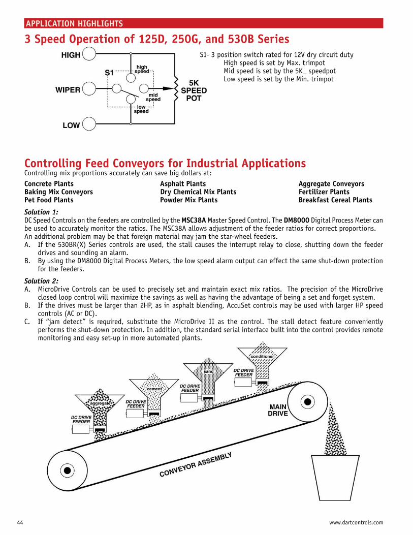
APPLICATION HIGHLIGHTS
3 Speed Operation of 125D, 250G, and 530B SeriesS1- 3 position switch rated for 12V dry circuit duty High speed is set by Max. trimpot Mid speed is set by the 5K_ speedpot Low speed is set by the Min. trimpot
Controlling Feed Conveyors for Industrial ApplicationsControlling mix proportions accurately can save big dollars at:Concrete Plants Asphalt Plants Aggregate ConveyorsBaking Mix Conveyors Dry Chemical Mix Plants Fertilizer PlantsPet Food Plants Powder Mix Plants Breakfast Cereal Plants
Solution 1:DC Speed Controls on the feeders are controlled by the MSC38A Master Speed Control. The DM8000 Digital Process Meter can be used to accurately monitor the ratios. The MSC38A allows adjustment of the feeder ratios for correct proportions. An additional problem may be that foreign material may jam the star-wheel feeders.A. If the 530BR(X) Series controls are used, the stall causes the interrupt relay to close, shutting down the feeder drives and sounding an alarm.B. By using the DM8000 Digital Process Meters, the low speed alarm output can effect the same shut-down protection for the feeders.
Solution 2:A. MicroDrive Controls can be used to precisely set and maintain exact mix ratios. The precision of the MicroDrive closed loop control will maximize the savings as well as having the advantage of being a set and forget system. B. If the drives must be larger than 2HP, as in asphalt blending, AccuSet controls may be used with larger HP speed controls (AC or DC). C. If “jam detect” is required, substitute the MicroDrive II as the control. The stall detect feature conveniently performs the shut-down protection. In addition, the standard serial interface built into the control provides remote monitoring and easy set-up in more automated plants.
44 www.dartcontrols.com
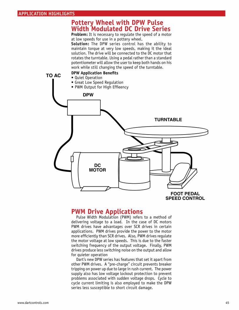
APPLICATION HIGHLIGHTS
PWM Drive ApplicationsPulse Width Modulation (PWM) refers to a method of
delivering voltage to a load. In the case of DC motors PWM drives have advantages over SCR drives in certain applications. PWM drives provide the power to the motor more efficiently than SCR drives. Also, PWM drives regulate the motor voltage at low speeds. This is due to the faster switching frequency of the output voltage. Finally, PWM drives produce less switching noise on the output and allow for quieter operation
Dart’s new DPW series has features that set it apart from other PWM drives. A “pre-charge” circuit prevents breaker tripping on power up due to large in rush current. The power supply also has low voltage lockout protection to prevent problems associated with sudden voltage drops. Cycle to cycle current limiting is also employed to make the DPW series less susceptible to short circuit damage.
Pottery Wheel with DPW Pulse Width Modulated DC Drive SeriesProblem: It is necessary to regulate the speed of a motor at low speeds for use in a pottery wheel.Solution: The DPW series control has the ability to maintain torque at very low speeds, making it the ideal solution. The drive will be connected to the DC motor that rotates the turntable. Using a pedal rather than a standard potentiometer will allow the user to keep both hands on his work while still changing the speed of the turntable.DPW Application Benefits
45www.dartcontrols.com
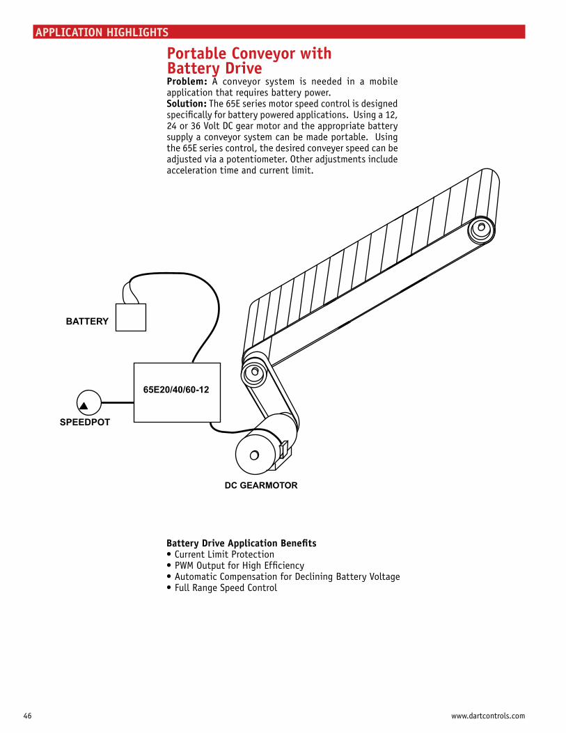
APPLICATION HIGHLIGHTS
Portable Conveyor with Battery DriveProblem: A conveyor system is needed in a mobile application that requires battery power.Solution: The 65E series motor speed control is designed specifically for battery powered applications. Using a 12, 24 or 36 Volt DC gear motor and the appropriate battery supply a conveyor system can be made portable. Using the 65E series control, the desired conveyer speed can be adjusted via a potentiometer. Other adjustments include acceleration time and current limit.
Battery Drive Application Benefits
46 www.dartcontrols.com
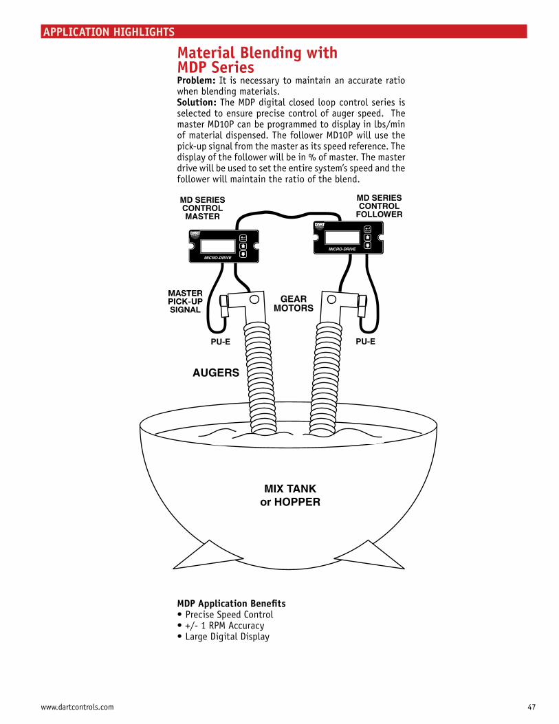
APPLICATION HIGHLIGHTS
Material Blending with MDP SeriesProblem: It is necessary to maintain an accurate ratio when blending materials.Solution: The MDP digital closed loop control series is selected to ensure precise control of auger speed. The master MD10P can be programmed to display in lbs/min of material dispensed. The follower MD10P will use the pick-up signal from the master as its speed reference. The
drive will be used to set the entire system’s speed and the follower will maintain the ratio of the blend.
MDP Application Benefits
47www.dartcontrols.com
A CUSTOMER-DRIVEN COMPANY
Accent on ProductDar t is the most responsive
manufacturer of controls anywhere. We listen to our customers’ needs and respond with the control product that best fits their special requirements.
For product and applicat ion assistance, please contact us.
controls for AC line voltage to three horsepower
controls
systems
and time
© 2008 Dart Controls, Inc. 508-5M LTMSCAT11
Accent on ServiceDa r t ha s r e f ined i t s l e an
manufacturing process to be able to schedule production runs in multiple quantities and models.
We can promise shipment the same day on standard products and within five days for specials.
major cities, U.S.A., Canada, and selected overseas countries.
states and Canada.
Dart Controls Headquarters Contacts:Customer Service
(317) 733-2133 ext. [email protected] and shipment information, order placement, and warranty.
Sales Department
(317) [email protected]
Application Support
(317) 733-2133 ext. [email protected] information and application assistance.
Technical Support
(317) 733-2133 ext. 465 or ext. [email protected]
Customer Feedback
(317) [email protected]
Manufacturer of High Quality Motor Speed Controls and Accessories Since 1963.
P.O. Box 105000 W. 106th StreetZionsville, Indiana 46077Phone: (317) 873-5211FAX: (317) 873-1105
For the most recent updates on Dart product innovations, see our website at:
www.dartcontrols.com
Available From: