ylua0078 - 0158 style a 60 hz, ylua0248 - 0498 style a 50
TRANSCRIPT

WIRING New Release Form 150.73-W1 (809)
R-410A
AIR-COOLED SCROLL CONDENSING UNITS
AIR-COOLED SCROLL CONDENSING UNITS
YLUA0248 - YLUA0498 STYLE A (50 Hz) 70 - 135 TON (245-475 KW)YLUA0078 - YLUA0158 STYLE A (60 Hz) 80 - 160 TON (281-522 KW)
JOHNSON CONTROLS2
Form 150.73-W1 (809)
This equipment is a relatively complicated apparatus. During installation, operation, maintenance or service, individuals may be exposed to certain components or conditions including, but not limited to: refrigerants, oils, materials under pressure, rotating components, and both high and low voltage. Each of these items has the potential, if misused or handled improperly, to cause bodily injury or death. It is the obligation and responsibility of operating/service personnel to identify and recognize these inherent hazards, protect themselves, and proceed safely in completing their tasks. Failure to comply with any of these requirements could result in serious damage to the equipment and the property in
IMPORTANT!READ BEFORE PROCEEDING!
GENERAL SAFETY GUIDELINES
which it is situated, as well as severe personal injury or death to themselves and people at the site.
This document is intended for use by owner-authorized operating/service personnel. It is expected that this individual possesses independent training that will enable them to perform their assigned tasks properly and safely. It is essential that, prior to performing any task on this equipment, this individual shall have read and understood this document and any referenced materials. This individual shall also be familiar with and comply with all applicable governmental standards and regulations pertaining to the task in question.
SAFETY SYMBOLSThe following symbols are used in this document to alert the reader to areas of potential hazard:
CAUTION identifies a hazard which could lead to damage to the machine, damage to other equipment and/or environmental pollution. Usually an instruction will be given, together with a brief explanation.
NOTE is used to highlight additional information which may be helpful to you.
DANGER indicates an imminently hazardous situation which, if not avoided, will result in death or serious injury.
WARNING indicates a potentially hazardous situation which, if not avoided, could result in death or se-rious injury.
External wiring, unless specified as an optional connection in the manufacturer’s product line, is not to be connected inside the micro panel cabinet. Devices such as relays, switches, transducers and controls may not be installed inside the panel. no external wiring is al-lowed to be run through the micro panel. All wiring must be in accordance with Johnson Controlspublished specifications and must be performed only by qualified Johnson Controls personnel. Johnson Controls will not be responsible for damages/problems resulting from improper connections to the controls or application of improper control signals. Failure to follow this will void the manufacturer’s warranty and cause serious damage to property or injury to persons.

Form 150.73-W1 (809)
3JOHNSON CONTROLS
In complying with Johnson Controls policy for continuous product improvement, the information contained in this document is subject to change without notice. While Johnson Controls makes no commitment to update or provide current information automatically to the manual owner, that information, if applicable, can be obtained by contacting the nearest Johnson Controls Service office.
List of figuresfig. 1 – eLementary Wiring Diagram, sht 1 ................................................................................8fig. 2 – eLementary Wiring Diagram, sht 2 ..............................................................................10fig. 3 – eLementary Wiring Diagram, sht 3 ..............................................................................12fig. 4 – eLementary Wiring Diagram, sht 6 ..............................................................................14fig. 5 – eLementary Wiring Diagram, sht 14 ............................................................................16fig. 6 – eLementary Wiring Diagram, sht 16 ............................................................................18fig. 7 – connection Diagram, sht 1 ............................................................................................20fig. 8 – connection Diagram, sht 2 ............................................................................................22fig. 9 – connection Diagram, sht 3 ............................................................................................24fig. 10 – connection Diagram, sht 5 ............................................................................................26fig. 11 – connection Diagram, sht 6 .............................................................................................28fig. 12 – connection Diagram, sht 7 ............................................................................................30
changeaBiLity of this DocumentIt is the responsibility of operating/service personnel to verify the applicability of these documents to the equipment in question. If there is any question in the mind of operating/service personnel as to the applicability of these documents, then prior to working on the equipment, they should verify with the owner whether the equipment has been modified and if current literature is available.

JOHNSON CONTROLS4
Form 150.73-W1 (809)
ELECTRICAL NOTES AND LEGEND
DESIGNATION DESCRIPTIONACC ACCESSORY
- ADIS DISPLAY BOARD
- AMB MICRO BOARD
- BAMB AMBIENT
- BDAT DISCHARGE AIR TEMPERATURE
- BDP DISCHARGE PRESSURE
- BECT ENTRING CHILLED TEMPERATURE
- BLCT LEAVING CHILLED TEMPERATURENOT FITTED ON REMOTE EVAP UNITS
-BMP MOTOR PROTECTOR COMPRESSOR
- BSP SUCTION PRESSURE
- CPF CAPACITOR POWER FACTOR
- ECH CRANKCASE HEATER
- EEH EVAPORATOR HEATER
- EHRH HEAT RECOVERY HEATER
- EPH PUMP HEATER
- EXT EXTERNAL TO CONTROL PANEL
- F FUSE
- FHP HIGH PRESSURE CUTOUT
- FSC FAN SPEED CONTROLLER
- FSI FAN SPEED INHIBIT TWO SPEEDFAN OPTION ONLY
GND GROUND
G/Y GREEN / YELLOW
J PLUG BOARD CONNECTOR
- K CIRCUIT BOARD RELAY
- KF FAN CONTACTOR LINE(INCLUDING COIL SUPPRESSOR)
- KFH FAN CONTACTOR HIGH SPEED(INCLUDING COIL SUPPRESSOR)
- KFL FAN CONTACTOR LOW SPEED(INCLUDING COIL SUPPRESSOR)
- KFOL FAN OVERLOAD
- KFS RELAY FAN SPEED
- KH HEATER RELAY
- KM COMPRESSOR CONTACTOR (INCLUD-ING COIL SUPPRESSOR)
- KCR CONTROL RELAY
- KP PUMP CONTACTOR PART(INCLUDING COIL SUPPRESSOR)
- KT RELAY TIMER
- M COMPRESSOR MOTOR
DESIGNATION DESCRIPTION- MF MOTOR FAN
- MP MOTOR PUMP
NU NOT USED
PE PROTECTIVE EARTH
PWM PULSE WIDTH MODULATION TEMP RE-SET or REMOTE UNLOAD 2nd STEP
- QCB CIRCUIT BREAKER
- QMMSC MANUAL MOTOR STARTER COMPRESSOR
- QMMSP MANUAL MOTOR STARTER PUMP
- QSD SWITCH DISCONNECT
R RESISTOR
RED RED
RP RUN PERMISSIVE
RU REMOTE UNLOAD 1st STEP
SCH THERMOSTAT CRANKCASE HEATER
SCR SCREEN
- SF FLOW SWITCH
- SKP KEYPAD
- SOA SWITCH OFF AUTO
- SZT ZONE THERMOSTAT
- T TRANSFORMER
- TC TRANSFORMER CURRENT
- UBR BRIGDE RECFIFIER
- WHT WHITE
- XP PLUGS BETWEEN POW./MICRO.SECTION
- XTBC TERMINAL BLOCK CUSTOMER
- XTBF TERMINAL BLOCK FACTORY
- YESV EVAPORATOR SOLENOID VALVE
- YHGSV HOT GAS SOLENOID VALVE (INCLUDING COIL SUPPRESSOR)
- YLLSVLIQUID LINE SOLENOID VALVE FIELD MOUNTED AND WIRED ON REMOTE EVAP. UNITS
- ZCPR COMPRESSOR
NB NOTE WELL {SEE NOTE}
WIRING AND ITEMS SHOWN THUS ARE STANDARD YORK ACCESSORIES
WIRING AND ITEMS SHOWN THUS ARE NOT SUPPLIED BY YORK
ITEMS THUS ENCLOSED FORM A COM-PONENTS OR SETS OF COMPONENTS
035-21966-101 REVG

Form 150.73-W1 (809)
5JOHNSON CONTROLS
035-21966-101 REVG
ELECTRICAL NOTES AND LEGEND (CONTINUED)
GENERAL
a. This drawing is based on IEC symbols.
b. Field wiring to be in accordance with the relevant electrical code as well as all other applicable codes and specifications.
C. all sources of supply shown on this diagram to be taken from one main isolator, not shown or supplied by YORK.
d.Green and yellow wire is used for earth, multi-colored cable used for low voltage. Red wire used for aC Control, blue wire for neutral, black wire for aC and dC power. Orange wire should be used for interlock control wiring supplied by external source.
E.Legend designation depicts component abbreviations. Number prefix located, if applicable, on schematic circuit, refers to system thereon, E.G. = 1-FHP2 refers to high pressure cutout no 2 on system no 1.
F.
all wiring to control section voltage free contacts requires a supply provided by the customer maximum voltage 120 volts. The customer must take particular care when deriving the supplies for the voltage free terminals with regard to a common point of isolation. Thus, these circuits when used must be fed via the common point of isolation the voltage to these circuits is removed when the common point of isolation to the unit is opened. This common point of isolation is not supplied by YORK. The YORK voltage free contacts are rated at 100va. all inductive devices {relays} switch by the YORK voltage free contacts must have their coil suppressed using standard R/C suppressors.
G. Customer voltage free contacts connected to terminal 13 must be rated at 30V 5ma.
H.No controls {relays etc.} Should be mounted in any section of the control panel. additionally, control wiring not connected to the YORK control panel should not be run through the panel. If these precautions are not followed, electrical noise could cause malfunctions or damage to the unit and its controls.
I 120/14.3 -(Signal Input) i.e. 120 is wire # and 14.3 refers to sht. 14 column 3
Notes
1Refer to installation commissioning operation and maintenance manual for customer connections and customer connection notes, non compliance to these instructions will invalidate unit warranty.
2Wiring and components for compressor 3 only fitted when unit has 3 compressors on the system. 1-BMP3 is replaced by a link across terminals 134 & 135. 2-BMP3 is replaced by a link across terminals 234 & 235.
3 When not fitted 1-FHP2 is replaced by a link across terminals 132 & 139. 2-FHP2 is replaced by a link across terminals 232 & 239.
4 Fitted on units with hot gas bypass option.
5 EMS option is wired as shown.
6 This wiring must be used for old display 031-0110-000.
7 Network connection point.
8 Printer port.
9 Remote emergency stop can be wired between terminal L and 5 after removing link.
10 Power factor correction accessory. Power factor correction fitted to each compressor contactor.
11Not fitted on compressors with internal motor protection. For system 1 terminals 132 & 133, 133 & 134 and 134 & 135 are linked. For system 2 terminals 232 & 233, 233 & 234 and 234 & 235 are linked.
12 Only fitted on systems with 3 or 4 fans.
13 Only fitted on systems with 4 fans.
14 Only fitted on systems with 5 fans.
15 Only fitted on systems with 6 fans.
16 Input switch disconnect (standard on CE units) or circuit breaker option replaces input terminal block.
17 Input switch disconnect & individual system circuit breaker option replaces input terminal block.
18 115V control circuit requires a 115V supply unless control circuit transformer -T2 & -F3 are fitted (standard on CE units).
19For optional hydro kit. Heater -EPH is fitted and wired as shown. On single pump -KP1, -QMMSP1 & -MP1 are fitted & wired as shown. On two pump hydro kits -KP2, -QMMSP2 & -MP2 are also fitted and wired as shown.
20 Current measurement option wired as show.
21 Only fitted on systems with single speed fans.
22 Only fitted on systems with two speed fans.
23 Optional compressor manual motors starters (standard on CE units).
24 See sheet 3 of connection diagram for power input options.
25 alternate connections shown for different two speed motor types.
26 Only fitted on systems with a maximum of 4 fans.
27 220/230V units require a separate fuse for units w/4 or more fans per system.
28 Low ambient kit -FSC for fan -MF1 is only fitted on systems with less than 4 fans.

JOHNSON CONTROLS6
Form 150.73-W1 (809)YLAA WIRING
29 Only fitted on YLUA0098.
30 Only fitted on YLUA0095, 0098 & 0148.
31 Input dual point circuit breaker option replaces input terminal block.
32 Field installed on remote evaporator units.
33 Fitted on units with single phase motors only
34 Fitted on units with low ambient option only
35 Only fitted on units with an acoustic kit
36 Only fitted on heat recovery units
37 Only fitted on condensing units
38 Omitted on condensing units
ELECTRICAL NOTES AND LEGEND (CONTINUED)

THIS PAGE INTENTIONALLY LEFT BLANK
1

JOHNSON CONTROLS8
Form 150.73-W1 (809)
WIRING DIAGRAMS
FIG. 1 – ELEMENTARY WIRING DIAGRAM, SHT 1
ELEMENTARY WIRING DIAGRAMS
035-21583-101 REV D035-21583-101 REV D

Form 150.73-W1 (809)
9JOHNSON CONTROLS
035-21583-101 REV D

JOHNSON CONTROLS10
Form 150.73-W1 (809)
FIG. 2 – ELEMENTARY WIRING DIAGRAM, SHT 2
035-21583-102 REVD035-21583-102 REV D

Form 150.73-W1 (809)
11JOHNSON CONTROLS
035-21583-102 REVD

JOHNSON CONTROLS12
Form 150.73-W1 (809)
FIG. 3 – ELEMENTARY WIRING DIAGRAM, SHT 3LD13992A
035-21583-103 REV. B035-21583-103 REV B

Form 150.73-W1 (809)
13JOHNSON CONTROLS
LD13993A
1

JOHNSON CONTROLS14
Form 150.73-W1 (809)
WIRING
LD13238FIG. 4 – ELEMENTARY WIRING DIAGRAM, SHT 6
035-21583-106 REVA035-21583-106 REV A

Form 150.73-W1 (809)
15JOHNSON CONTROLS
LD13239

JOHNSON CONTROLS16
Form 150.73-W1 (809)
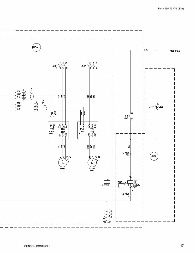
FIG. 5 – ELEMENTARY WIRING DIAGRAM, SHT 14
035-21583-114 REV D
Form 150.73-W1 (809)
17JOHNSON CONTROLS

JOHNSON CONTROLS18
Form 150.73-W1 (809)
FIG. 6 – ELEMENTARY WIRING DIAGRAM, SHT 16
035-21583-116_rev -035-21583-116 REV -

THIS PAGE INTENTIONALLY LEFT BLANK

JOHNSON CONTROLS20
Form 150.73-W1 (809)
FIG. 7 – CONNECTION DIAGRAM, SHT 1
035-21589-101 REVC035-21589-101 REV C
CONNECTION WIRING DIAGRAMS

Form 150.73-W1 (809)
21JOHNSON CONTROLS
035-21589-101 REVC
JOHNSON CONTROLS22
Form 150.73-W1 (809)
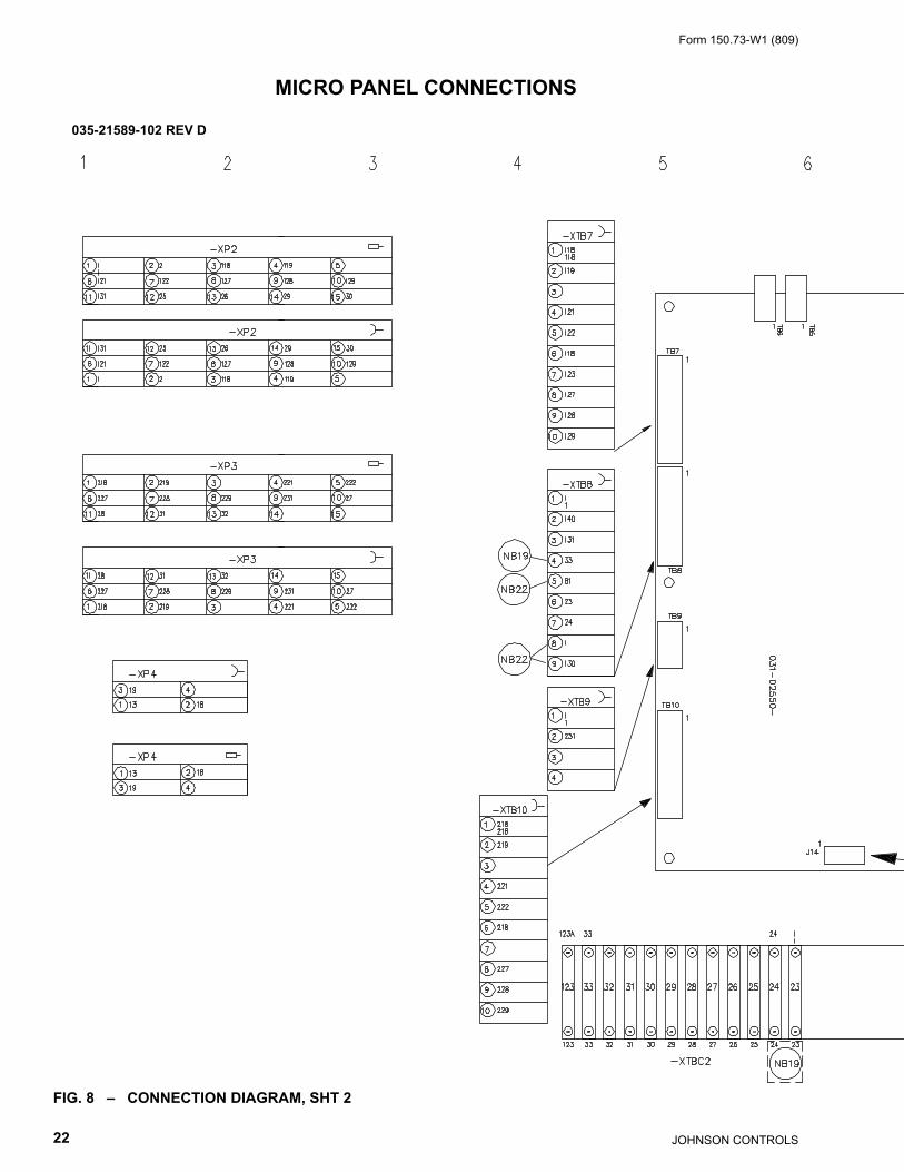
FIG. 8 – CONNECTION DIAGRAM, SHT 2
MICRO PANEL CONNECTIONS
035-21589-102 REVD035-21589-102 REV D

Form 150.73-W1 (809)
23JOHNSON CONTROLS
035-21589-102 REVD

JOHNSON CONTROLS24
Form 150.73-W1 (809)
POWER OPTIONS
FIG. 9 – CONNECTION DIAGRAM, SHT 3
LD13234A
035-21589-103 REVB035-21589-103 REV B

Form 150.73-W1 (809)
25JOHNSON CONTROLS
LD13901

JOHNSON CONTROLS26
Form 150.73-W1 (809)
FIG. 10 – CONNECTION DIAGRAM, SHT 5
035-21589-105 REVA035-21589-105 REV A

Form 150.73-W1 (809)
27JOHNSON CONTROLS
035-21589-105 REVA

JOHNSON CONTROLS28
Form 150.73-W1 (809)
FIG. 11 – CONNECTION DIAGRAM, SHT 6
035-21589-106 REVE035-21589-106 REV E

Form 150.73-W1 (809)
29JOHNSON CONTROLS
035-21589-106 REVE

JOHNSON CONTROLS30
Form 150.73-W1 (809)
FIG. 12 – CONNECTION DIAGRAM, SHT 7
035-21589-107 REV A035-21589-107 REV A

Form 150.73-W1 (809)
31JOHNSON CONTROLS
035-21589-107 REV A

©2009 Johnson Controls, Inc. P.O. Box 423, Milwaukee, WI 53203www.johnsoncontrols.com
Printed in USA 150.73-W1 (809)New Release