yiannis mouzouris and john e. scharer- modeling of profile effects for inductive helicon plasma...
TRANSCRIPT

8/3/2019 Yiannis Mouzouris and John E. Scharer- Modeling of Profile Effects for Inductive Helicon Plasma Sources
http://slidepdf.com/reader/full/yiannis-mouzouris-and-john-e-scharer-modeling-of-profile-effects-for-inductive 1/9
152 IEEE TRANSACTIONS ON PLASMA SCIENCE, VOL. 24 , NO 1, FEBRUARY 1996
ffects for Inductive
asma SourcesYiannis Mouzouris and John E. Scharer, Member, IEEE
Abstract-A computer code for modeling existing and new
helicon sources for materials processing has been developed.
The Nagoya type-111, helical, and Stix coil antennas have been
modeled to study and examine plasma density and temperature
profile effects on power absorption of a small fraction ( n f e / n eN
5%) of fast electrons (T,+,* N 40 eV) which provide ionization
of the neutral gas in the experiment, and bulk (T,,1,, N 3 eV)
electron distributions in an argon gas. The “ANTENA” computer
code, originally written by B. McVey to study ion cyclotron waves,
was modified and used to study and model helicon sources. Acollisional model that includes radial density and temperature
profiles was added to the code to study the effect of collisions on
the heating mechanisms. The competing effects of collisional and
Landau damping heating mechanisms have been investigated in
detail, and results indicate that collisions playan mportant roleinthe plasma absorption profile at high densities (ne2 1013emp3).
The radio frequency wave absorption profiles are sensitive to the
plasma density and temperature profiles. The partial-turn helix
antenna, that solely excites them = +1 azimuthal mode, is found
to be more efficient in coupling the power to an assumed plasma
profile than the Nagoya type-111. The Stix coil is also found to be
promising due to its on-axis peaking of the wave heating fields.
I. INTRODUCTION
LASMA etching has been one of the key technologiessince 1970 [l] for the fabrication of semiconductor inte-
grated circuits and microelectronic devices. A recent reviewpaper [2] shows that the conventional capacitively coupled
RF discharge plasma source does not appear to satisfy allthe etching requirements for the ultra large scale integration(ULSI) (> lo6 devicedcircuit) technology. Therefore, it is nec-
essary to search for other plasma sources. Electron cyclotron
resonance (ECR), inductively coupled planar, and heliconsources are examples of plasma sources that can overcomethe limitations of the RF capacitively coupled discharges.These sources operate at low pressures ( 5 5 mtorr) (allowinganisotropic etching), high densities (higher etch rates), andprovide reasonable uniformity. Helicon sources, which havea higher ionization efficiency and flux density, are easier tooperate due to their higher radiation resistance and readilymatched input impedance. They can sometimes be operatedin weaker magnetic fields (Bo 50-100 G) than resonant
ECR sources (Bo 1 kG). Magnetic fields up to 2 kG havebeen employed in experiments [3]-[6] for fundamental helicon
plasma source and wave studies.
Manuscript received January 30, 1995; revised November 24, 1995. Thiswork was supported by the Graduate School of the University of Wisconsin-Madison, and in part by AFOSR Grant F49620-94-1-0054,
The authors are with th e Department of Electrical and Computer Engineer-ing, University of Wisconsin, Madison, WI 53706 USA.
Publisher Item Identifier S 0093-3813(96)02193-5.
In 1970, Boswell [7] found that a high-density plasma couldbe produced by the excitation of helicon waves in a cylindrical
plasma. Experiments done by Boswell and his group show thatpeak densities on the order of 4 x lo1’ cmp3 in an argon gas
could be produced with only 600 W of 8 MHz power in a 5-cm radius tube. Shoji et al. [6] used helical coils to excite them = +1 or m = -1 azimuthal mode separately, depending
on the direction of the static magnetic field. They obtained a
higher plasma density cmp3) with the m = $1 mode
than with the m = -1 mode.
Chen [SI has suggested Landau damping of the heliconwave as a possible mechanism for efficient energy transferbetween the fast ionizing electrons and the wave. Experimentalevidence of Landau damping on bulk slow electrons andprimary fast electrons at lower densities has been presentedby Komori [4], Chen [5], and Loewenhardt [9], [lo]. Komorialso showed that collisional damping ‘is significant at high
densities (ne2 x 10I2 ~ m - ~ )nd plays an important role
in transferring the energy to the electrons. In particular, he
shows that both Landau and collisional damping processes areimportant in the density range of ne M 10I2- x cmP3.
In this paper, modeling of helicon sources has been studiedwith the aid of the computer code “ANTENA” [Ill, [12]that models the radio frequency antenna-plasma interaction.This code calculates the three-dimensional (3-D) electromag-
netic plasma fields in a one-dimensional (1-D) cylindrical hotmagnetized plasma surrounded by an RF inductive coil. Wehave modified this code to study and analyze helical antennas,
along with the Nagoya type-I11 and m = 0 Stix coil, for
the plasma absorption profile of high-density plasma sources
in the lower hybrid frequency range. These antennas cancouple into a helicon mode wave propagating at frequenciesnear the lower hybrid frequency. We examine cases wherethe frequency is in the neighborhood of the lower hybridfrequency with an objective of obtaining a broad core heatingprofile. The “ANTENA” code treats the bulk fast and slowwaves that propagate in the column subject to the inductiveantenna spectrum and radial plasma boundary conditions. We
will focus and study wave-particle physics that take place in
the source region, where the RF power is coupled from theantenna to the plasma. In this region, the magnetic field isassumed to be uniform, and therefore, the code can be appliedto accurately describe the antenna-plasma coupling.
An introduction to the physics of the “ANTENA” code, aswell as the spatial current distribution of the modeled antennas,is presented in Section 11. In Section 111,we discuss modelingresults of existing and new helicon sources, obtained from the“ANTENA” code. Section IV describes the conclusions.
0093-3813/96$05.00 0 99 6 IEEE ,
8/3/2019 Yiannis Mouzouris and John E. Scharer- Modeling of Profile Effects for Inductive Helicon Plasma Sources
http://slidepdf.com/reader/full/yiannis-mouzouris-and-john-e-scharer-modeling-of-profile-effects-for-inductive 2/9
MOUZOURIS AN D SCHARE R INDUCTIVE HELICON PLASMA SOURCES 153
Full Turn Loop Nagoya Type-I11
a = plasma radiusb = antenna radiusc = conducting tube radius
Fractional Helix Integral Helix (1 urn)
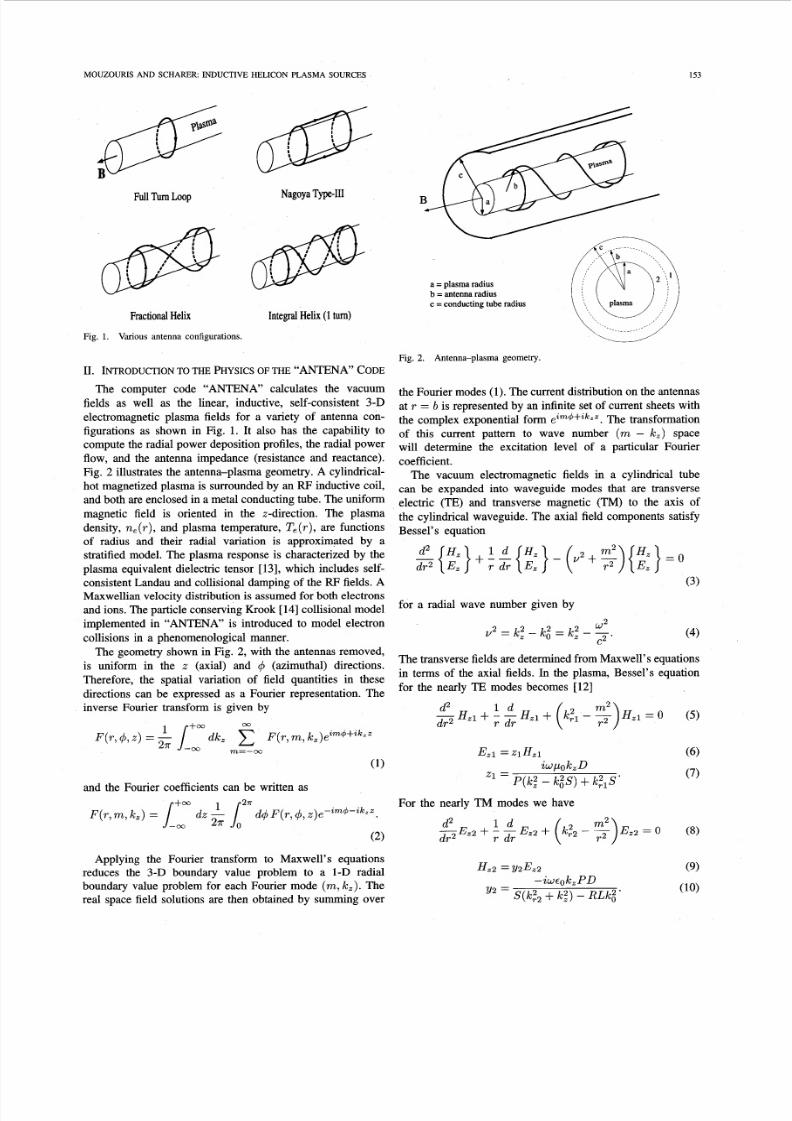
Fig. 1. Various antenna configurations.
Fig. 2. Antenna-plasma geometry.
11. INTRODUCTION TO THE PHYSICS OF T H E “ANTE”’ C O D E
The computer code “ANTENA” calculates the vacuum
fields as well as the linear, inductive, self-consistent 3-D
electromagnetic plasma fields for a variety of antenna con-
figurations as shown in Fig. 1. It also has the capability tocompute the radial power deposition profiles, the radial power
flow, and the antenna impedance (resistance and reactance).Fig. 2 illustrates the antenna-plasma geometry. A cylindrical-
hot magnetized plasma is surrounded by an RF nductive coil,
and both are enclosed in a metal conducting tube. The uniform
magnetic field is oriented in the z-direction. The plasma
density, ne T ) , and plasma temperature, Te(r),re functionsof radius and their radial variation is approximated by astratified model. The plasma response is characterized by the
plasma equivalent dielectric tensor [131, which includes self-consistent Landau and collisional damping of the RF ields. AMaxwellian velocity distribution is assumed for both electronsand ions. The particle conservingKrook [14] collisional modelimplemented in “ANTENA” is introduced to model electron
collisions in a phenomenological manner.
The geometry shown in Fig. 2, with the antennas removed,
is uniform in the z (axial) and 4 (azimuthal) directions.Therefore, the spatial variation of field quantities in these
directions can be expressed as a Fourier representation. The
inverse Fourier transform is given by
and the Fourier coefficients can be written as
Applying the Fourier transform to Maxwell’s equationsreduces the 3-D boundary value problem to a 1-D radialboundary value problem for each Fourier mode (m , ,) . Thereal space field solutions are then obtained by summing over
the Fourier modes (1). The current distribution on the antennas
at r = b is represented by an infinite set of current sheets withthe complex exponential form eim++ikzz.The transformation
of this current pattern to wave number (m - k z ) spacewill determine the excitation level of a particular Fourier
coefficient.The vacuum electromagnetic fields in a cylindrical tube
can be expanded into waveguide modes that are transverse
electric (TE) and transverse magnetic (TM) to the axis of
the cylindrical waveguide. The axial field components satisfy
Bessel’s equation
I d H ,
${z}; & { E , } - U 2 +
$){z} (3)
for a radial wave number given by
(4)
The transverse fields are determined from Maxwell’s equations
in terms of the axial fields. In the plasma, Bessel’s equation
for the nearly TE modes becomes [12]
For the nearly TM modes we have
d 2 I d-E,2r 2 + --r Ez2 +

8/3/2019 Yiannis Mouzouris and John E. Scharer- Modeling of Profile Effects for Inductive Helicon Plasma Sources
http://slidepdf.com/reader/full/yiannis-mouzouris-and-john-e-scharer-modeling-of-profile-effects-for-inductive 3/9
154 EE E TRANSACTIONS ON PLASMA SCIENCE, VOL. 24, NO. 1, FEBRUARY 1996
The radial wavenumbers k , l , k,a are defined by
Sk:2 + k,2,[k,”(S+ P ) - k,2(SP+ RL)]
+ P ( k 2 - k ; ) ( g - k ; L ) = 0. (11)
The plasma is represented by the well-known elements of
the “Stix” equivalent dielectric tensor [131
S - i D
t‘= b’ ;] (12)
where the component P includes both collisional and Landaudamping effects, and is given by
(14)w + u, + nw,,
k , v,5% =
where 2 s the plasma dispersion function tabulated by Fried
and Conte [15]
ImC>O
and
a = species (electrons, ions, etc.),Ip, = = plasma frequency,
w,, = ‘aB = cyclotron frequency,ma
‘U = /% = thermal velocity,
U , = collision frequency for species a.
Returning to (l), the smaller root ( k , ~ ) s assigned to thenearly transverse electric modes and the larger root ( k , 2 ) to
the nearly transverse magnetic modes. The total axial plasmafields are given by
H, = Hzi + y2&2 (15)
E, =ziH,i + E a 2 . (16)
The axial components H , l ( r ) and E,a(r) each separately
satisfy Bessel’s equation, and the transverse plasma fields
E,, E4 ) H, ) H+ are determined from the axial components.The above general solutions are solved by imposing boundaryconditions at the interface between the three regions shownin Fig. 2.
At the conducting tube radius r = c, the tangential compo-nents of the electric field must vanish
E4 = E, = 0.
Across the plasma-vacuum boundary at r = a, the tangentialcomponentsof the electric and magnetic fields are continuous.
That is
E; x E $ ) E,“ = E:
HZ = H g ) H,” = H,”
where the superscript v denotes vacuum, and p the plasmaregion. Across the current sheet at r = b, the tangential
components of the electric field are continuous and those of
the magnetic field are discontinuous, according to Ampere’slaw. Therefore, we can write
H,” - HE = J+
Hi - H j = J ,
where regions 1 and 2 are shown in Fig. 2.
A . Current Distribution on the Antennas
The current distribution characterizing the antennas shownin Fig. 1 is calculated in this section. Due to the uniformity ofthe geometry in the qb and z directions, the spatial variation ofthe current distribution of the antennas can be represented by
an infinite set of current sheets with the complex exponentialform ezm4+zLzz. he m - k , spectrum of the antennas, thatis, the Fourier coefficients of the current density, can be
applied directly since the current distribution is contained ina cylindrical surface of constant radius.
Assuming the current density of the antennas to besolenoidal (V . J = 0), we need to determine only the
azimuthal current density since the axial current density canbe calculated from the m - k , transform of the continuityequation. That is
(17)
The above low-frequency approximation of a stationary cur-rent distribution for the antennas (V .J = 0) implies that the
electrostatic fields due to the free charge on the antennas areeffectively shielded from the plasma and can be neglected.
1) Fractional Helix Coil: The fractional or partial-turn he-
lical antenna is diagrammed in Fig. 1. The fractional helix inthe limit of straight helical windings models the Nagoya type-IIIcoil. The current distribution is expressed in terms of deltaand heaviside functions
m
b k&(m, k , ) = - - -J4(m, k , ) .
. [U+(Q, 7r + e ) - U+ ( -7r + 8, B ) ] + s
’ [U$(-“ - e , -0 ) - U+ ( -Q , . i r - e) ]
z + -1 3
whereL = length of the coil,
i = T Z = (180”) (number of helical turns).
8/3/2019 Yiannis Mouzouris and John E. Scharer- Modeling of Profile Effects for Inductive Helicon Plasma Sources
http://slidepdf.com/reader/full/yiannis-mouzouris-and-john-e-scharer-modeling-of-profile-effects-for-inductive 4/9
MOUZOURIS AN D S CH A RER INDUCTIVE HELICON PLASMA SOURCES 155
The delta function is used to constrain the flow of the current
to radius T = b. The heaviside function u,[A(w/2)] is defined
as
w w W
U, (-2,p) = U, (f p)W W
1 for -- < z < + - (19)2 2= I otherwise.
The m - k , transform is determined from (2)
I . (20)e i (k ,L /2 )e im8 - - i ( k ,L /2 )e - im8
The fractional helix reduces to the Nagoya type-I11 case whenI 9 = 0.
111. HELICON OURCE MODELINGESULTS
A. ModiJications of the “AiVTENA” Code
The “ANTENA” code, written by McVey [ll], [12], wasprogrammed in FORTRAN language on the CRAY CTSScomputer system, to study ICRF (ion cyclotron range offrequencies) heating of magnetic fusion plasmas. We haveported the code from the CRAY facilities to our UNIX-basedworkstations using the graphics package PlPlot.
We decreased the cylindrical shell width and checked con-vergence (typically 800 radial points) for 2.5- and 5.0-cm radiistratified plasma density and temperature profiles. This allows
us to study the propagation of helicon waves in the frequencyrange, f N 1-30 MHz, which exhibit short wavelengths in theradial profile ( X l 2 1 mm). A typical run with 800 strata
(radial points) describing the stratified plasma density andtemperature profiles and assuming only one azimuthal moderequires about five minutes of run time on an IBM RS/6000model 370 workstation.
Helical coils, such as the fractional and integral helix shownin Fig. 1 have been analyzed and added to the code to examine
different types of helicon sources. The Stix coil [13], [16],which consists of an array of full-turn loops separated by adistance of X/2 and having alternative current flow directions,has been also modeled. Connecting two loops by a straighthorizontal wire provides a more accurate description of theStix coil. The Stix coil with the horizontal wire connection canalso excite other modes in addition to the m = 0 mode. Wehave found that the contribution to the radiation resistance of
the m = +1 and higher order modes is negligible compared tothe m = 0 mode, and thus we will focus on the model having
only the two full-turn loops for the description of the Stix coil.
B. Antenna Coupling
The antennas diagrammed in Fig. 1 were modeled to pri-marily excite m = $1 and m = 0 azimuthal modes forplasma production. The Nagoya type-I11 [17] and the helicalcoils primarily excite the m = +1, and the Stix coil, due toits azimuthal uniformity, primarily excites the m = 0 mode.
2.0
h 1.5ZNv
w“ 1.0
0.5
0.0
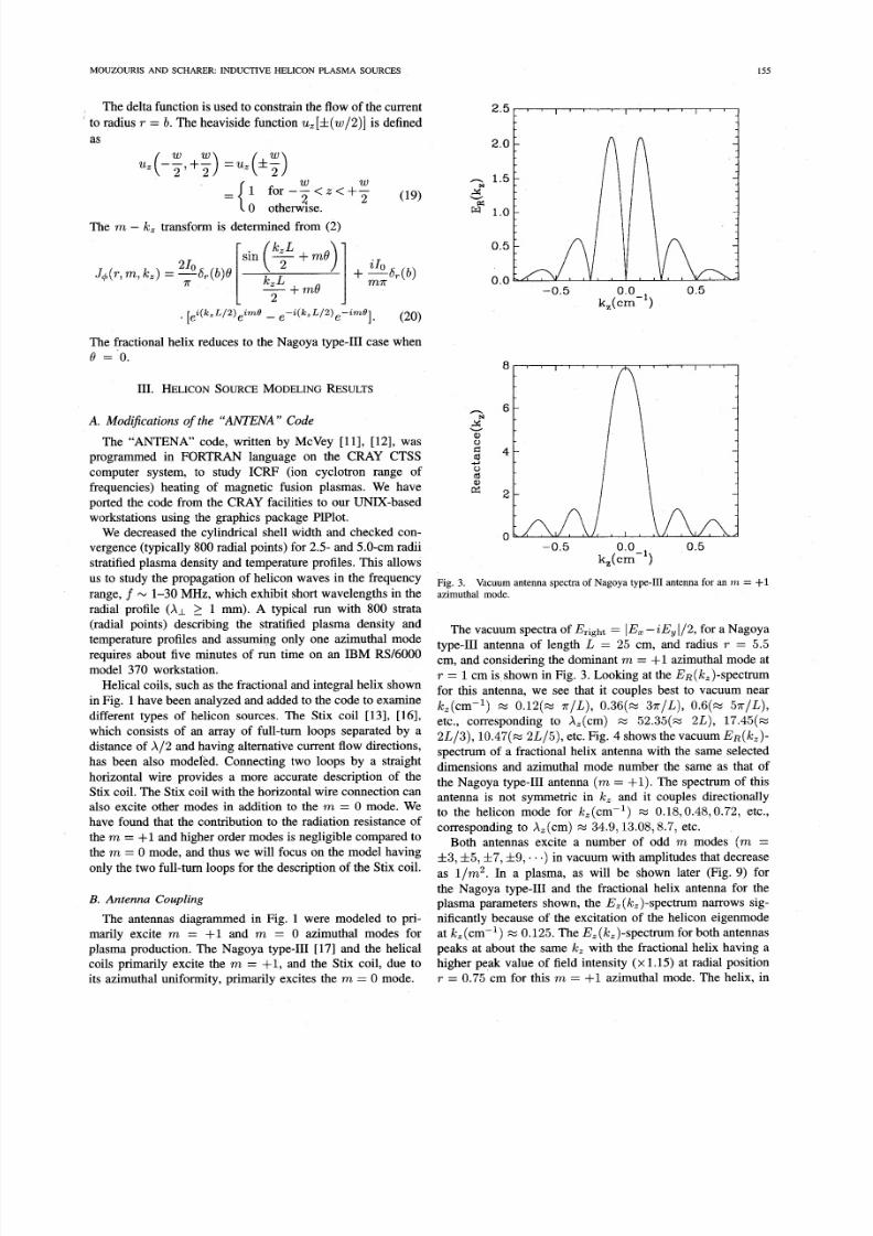
Fig. 3.
azimuthal mode.Vacuum antenna spectra of Nagoya type-I11 antenna for an m = +1
The vacuum spectra of Bright = IE, - Ey /2, for a Nagoyatype-I11 antenna of length L = 25 cm, and radius T = 5.5
cm, and considering the dominant m = +1 azimuthal mode atT = 1cm is shown in Fig. 3. Looking at the ER(lc,)-spectrumfor this antenna, we see that it couples best to vacuum nearIc,(cm-’) M 0 . 1 2 ( ~ r /L ) , 0 , 3 6 ( ~ 7r/L), 0 . 6 ( ~ .rr/L),
etc., corresponding to X,(cm) M 5 2 . 3 5 ( ~2L), 17.45(%2L/3) , 10 .4 7( ~L/5), etc. Fig. 4 shows the vacuum ER(^,)-spectrum of a fractional helix antenna with the same selecteddimensions and azimuthal mode number the same as that ofthe Nagoya type-I11 antenna (m = f l ) .The spectrum of thisantenna is not symmetric in k , and it couples directionallyto the helicon mode for k,(cm-l) M 0.18,0.48,0 .72, etc.,
corresponding to X,(cm)M
34.9,13.08,8.7, etc.Both antennas excite a number of odd m modes (m =
f 3 , 5 ,f7,.9,. . ) in vacuum with amplitudes that decrease
as l/m2. In a plasma, as will be shown later (Fig. 9) forthe Nagoya type-I11 and the fractional helix antenna for theplasma parameters shown, the E, (Ic,)-spectrum narrows sig-nificantly because of the excitation of the helicon eigenmodeat k,(cm-l) M 0.125. The E,(k,)-spectrum for both antennaspeaks at about the same k , with the fractional helix having ahigher peak value of field intensity (x 1.15) at radial positionT = 0.75 cm for this m = +1 azimuthal mode. The helix, in

8/3/2019 Yiannis Mouzouris and John E. Scharer- Modeling of Profile Effects for Inductive Helicon Plasma Sources
http://slidepdf.com/reader/full/yiannis-mouzouris-and-john-e-scharer-modeling-of-profile-effects-for-inductive 5/9
156 IEEE TRANSACTIONS ON PLASMA SCIENCE, VOL. 24, NO. 1, FEBRUARY 1996
Fig. 4.azimuthal mode.
Vacuum antenna spectra of fractional helix antenna for an m = +I
contrast to the Nagoya type-111, is strongly asymmetric in itsE,(k,) spectra in plasma.
The “ANTENA” code has the capability of computing the
radiation resistance and reactance of the inductive antennasshown in Fig. 1. The power transfered to the plasma can be.
written as
(21)
The impedance of the antenna is then written as
(22)
whereRA =
R, =
RL =
X A = antenna reactance.
The radiation resistance and the quality factor Q are im-portant parameters in determining the efficiency of couplingpower to the plasma. Radiated power contributes to the realpart of the antenna impedance whereas power stored in thenear field is represented by the reactive part of the impedance.
R, + RL = antenna resistance,radiation resistance of the antenna,skin loss resistance of the antenna,
TABLE I
IMPEDANCEND QUALITY FACTORQ p ) FOR VARIOUS NTENNASN A
PARABOLIC PLASMADENSITYROFILE n , ( r ) = n,o(l - ./u)~) AN D
Teo-fast= 40 eV, Te~-s low 3 eV, f = 7 MHz)
UNIFORMEMPERATUREROFILEBo = 70 0 G, n , ~ 2 x ~ m - ~ ,
A n t e n n a R e s i s t a n c e R e a ct a nc e Q p = w L / R
(0 ) (0 )
Nagoya type I11 1.36 7.70 5.66Fraction al helix 2.54 7.87 3.10
Stix 0.24 2.12 8.83
TABLE I1
IMPEDANCEND QUALITY FACTORQ p ) FOR VARIOUS NTENNASN A PLASMA
DENSITY ROFILEOFTHEORM e(?-) n,o(l - ./a)’))” AN D
Teo-fast= 40 eV ,Te~-s low 3 eV, f = 7 MHz)
UNIFORM EMPERATUREROFILEBo = 70 0 G, ne0 = 2 x ~ m - ~ ,
A n t e n n a R e s i s t a n c e R e a ct a nc e Q, = w L / R
(Q ) ( 0 )Nagoya type I11 0.72 10.10 14.02
Fraction al helix 2.11 10.20 4.83
Stix 0.14 2.17 15.17
TABLE I11
IMPELM” AND QUALITYACTORQ p ) OR VARIOUS ANTENNASN A PLASMA
DENSITY P R O F I L E O F T H E FORM ne (? )= I z ,o ( l - AND
UNIFORM EMPERATUREROFILEBo = 70 0 G,n,0 = 2 x c m P 3 ,
Teo-fast= 40 e V , T e o - s l o w = 3 e V , f = 7 MHz)
A n t e n n a R e s i s t a n c e R e a c t an c e 0, w L / Rr
( 0 ) (Q )
Nagoya type I11 0.35 11.30 32.28
Fr&tional helix 1.73 11.40 6.59
Stix 0.10 2.23 21.44
The overall quality factor, Q, can be determined from the
plasma Qp = wL/R, calculated from “ANTENA’ and resultsare shown in Tables 1-111, and the external matching network
Qc. That is, 1/Q = l /Q, + l /Qc .
The radiation resistance of the fractional helix, the Nagoyatype-HI antenna, and the Stix coil for three types of plasmadensity profiles was computed by integrating over all the
azimuthal mode numbers m. Tables 1-111 summarize these
results when both collisional and Landau damping processesare included. The antenna is centered at z = 0 cm, with length
L = 25 cm and radius T = 5.5 cm. The helical antenna has
a much higher value of radiation resistance and lower quality
factor than the Nagoya type-I11 for all three plasma profilesmodeled. Therefore, this antenna is more easily matched to anexternal generator and efficiently couples power to the plasma.
The higher radiation resistance of the helical antenna alsoallows efficient power coupling to the plasma with minimalskin effect losses on the coil structure. The impedance ofthe Stix coil (m = 0) was also computed. The Stix coilexcites a low-amplitude E, (k,)-spectrum compared to theother antennas as we will discuss later. It has the smallest
radiation resistance and also a large reactance which results in
a very large value of the quality factor Q. Therefore, it is it
more difficult to match the input power from the RF sourceto the antenna.
8/3/2019 Yiannis Mouzouris and John E. Scharer- Modeling of Profile Effects for Inductive Helicon Plasma Sources
http://slidepdf.com/reader/full/yiannis-mouzouris-and-john-e-scharer-modeling-of-profile-effects-for-inductive 6/9
MOUZOURIS AN D S CH A RER INDUCTIVE HELICON PLASMA SOURCES 157
1.4
1.2
4 1.0
E“ 0.8
3.r(
cue,
ed+ 0.6
’ .4
0.2 10.0 I I
I
20.0 40.0 60.0 80.0 100.0
z(cm)
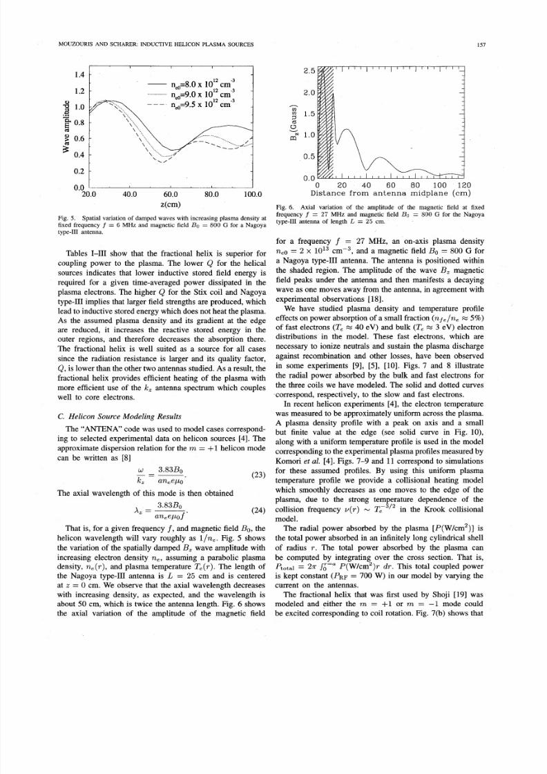
Fig. 5. Spatial variation of damped waves with increasing plasma density atfixed frequency f = 6 MHz and magnetic field Bo = 800 G for a Nagoyatype-I11 antenna.
Tables 1-111 show that the fractional helix is superior for
coupling power to the plasma. The lower Q for the helicalsources indicates that lower inductive stored field energy isrequired for a given time-averaged power dissipated in theplasma electrons. The higher Q for the Stix coil and Nagoyatype-I11 implies that larger field strengths are produced, whichlead to inductive stored energy which does not heat the plasma.As the assumed plasma density and its gradient at the edgeare reduced, it increases the reactive stored energy in theouter regions, and therefore decreases the absorption there.
The fractional helix is well suited as a source for all cases
since the radiation resistance is larger and its quality factor,Q, is lower than the other two antennas studied.As a result, thefractional helix provides efficient heating of the plasma with
more efficient use of the k , antenna spectrum which coupleswell to core electrons.
C. Helicon Source Modeling Results
The “ANTENA” code was used to model cases correspond-ing to selected experimental data on helicon sources [4]. The
approximate dispersion relation for the m = +1 helicon modecan be written as [8]
w - 3.83B0
k z aneepo’
-~The axial wavelength of this mode is then obtained
3.83B0A =
aneeP0.f ’
That is, for a given frequency f , nd magnetic field Bo, thehelicon wavelength will vary roughly as l /ne . Fig. 5 showsthe variation of the spatially damped B, wave amplitude with
increasing electron density n e , assuming a parabolic plasmadensity, ne(r) , nd plasma temperature T,(r). The length ofthe Nagoya type-I11 antenna is L = 25 cm and is centeredat z = 0 cm. We observe that the axial wavelength decreaseswith increasing density, as expected, and the wavelength isabout 50 cm, which is twice the antenna length. Fig. 6 showsthe axial variation of the amplitude of the magnetic field
2 .5
2.0
-)
1.52” 1. 00v
0. 5
0.00 2 0 40 60 80 100 12 0
Distance from antenna midplane (cm)
Fig. 6. Axial variation of the amplitude of the magnetic field at fixedfrequency f = 27 MHz and magnetic field Bo = 800 G for the Nagoyatype-I11 antenna of length L = 25 cm .
for a frequency f = 27 MHz, an on-axis plasma density
ne0 = 2 x 10¹³ cmP3, and a magnetic field Bo = 800 G for
a Nagoya type-I11 antenna. The antenna is positiQned withinthe shaded region. The amplitude of the wave B, magnetic
field peaks under the antenna and then manifests a decayingwave as one moves away from the antenna, in agreement withexperimental observations [181.
We have studied plasma density and temperature profileeffects on power absorption of a small fraction (n~ f , /n , 5%)
of fast electrons (T , = 40 eV) and bulk (T , % 3 eV) electrondistributions in the model. These fast electrons, which are
necessary to ionize neutrals and sustain the plasma discharge
against recombination and other losses, have been observedin some experiments [9], [5], [lo]. Figs. 7 and 8 illustratethe radial power absorbed by the bulk and fast electrons forthe three coils we have modeled. The solid and dotted curvescorrespond, respectively, to the slow and fast electrons.
In recent helicon experiments [4], the electron temperaturewas measured to be approximately uniform across the plasma.A plasma density profile with a peak on axis and a smallbut finite value at the edge (see solid curve in Fig. lo),along with a uniform temperature profile is used in the model
corresponding to the experimental plasma profiles measured byKomori et al. [4]. Figs. 7-9 and 11 correspond to simulationsfor these assumed profiles. By using this uniform plasmatemperature profile we provide a collisional heating modelwhich smoothly decreases as one moves to the edge of theplasma, due to the strong temperature dependence of the
collision frequency v ( r ) - T13’2 in the Krook collisional
model.The radial power absorbed by the plasma [P(W/cm2)] isthe total power absorbed in an infinitely long cylindrical shell
of radius T . The total power absorbed by the plasma canbe computed by integrating over the cross section. That is,
Ptotal 27r si=”P(W/cm2)r d r . This total coupled poweris kept constant (PRF 700 W) in our model by varying thecurrent on the antennas.
The fractional helix that was first used by Shoji [19] wasmodeled and either the m = +1 or m = -1 mode couldbe excited corresponding to coil rotation. Fig. 7(b) shows that

8/3/2019 Yiannis Mouzouris and John E. Scharer- Modeling of Profile Effects for Inductive Helicon Plasma Sources
http://slidepdf.com/reader/full/yiannis-mouzouris-and-john-e-scharer-modeling-of-profile-effects-for-inductive 7/9
IEEE TRANSACTIONS ON PLASMA SCIENCE, VOL. 24, NO . 1, FEBRUARY 1996
601 6 I I I I I I I I I ' I I I I 1 I I I I I I I
AN
E0\z=a
W
radius (em)
(a)
radius (em)
100, ' ' ' ' I ' ' I I " " " " " ' 4
20
0
0.0 0.5 1.0 1.5 2. 0 2.5
-
_ _ - -,.----; , I , , , ~
radius (cm)
(b )
Fig. 7. Radial power absorbed by the bulk (solid curve) and fast (dottedcurve) electrons for a fractional helix antenna, due to Landau and collisionaldamping of the helicon waves for the m = +1 mode and frequency f =7 MHz. (a) Low density ( n , ~ 1 x 10" ~ m - ~ , B o 25 0 G). (b) Highdensity ( n , ~ 2 x c m P 3 , B o = 700 G).
this antenna couples to a broad ( m= fl) plasma absorptionprofile at high densities ( n , ~ 2 x cmP3) in agreement
with the experiments done by Komori [4].The Stix coil [13], [16] has a heating profile and an
electric field E d ( k Z ) pectrum as shown in Figs. 8(b) and9(c). The model shows that the m = 0 azimuthal mode
fields provide substantial core heating. It also suggests that
the power absorbed by the plasma for all three antennas used
is, in part, due to Landau damping of the wave which heats
the fast electrons. This is illustrated in Fig. 9(a)-(c), wherethe E,(k,)-spectrum at the radial position T = 0.75 cmpeaks at about w/ k ,v t h M
a,here the Landau damping
rate is maximized. These fast electrons absorb the RF power
preferentially at the edge for high on-axis densities ( n , ~
2 x i o x 3 cmp3).I ) Collisional Effects on the Power Absorbed D ue to
u(ne,Te) rojile Effects: The competing effects of Landauand collisional damping of the helicon waves which heat
the electrons have been investigated in the density rangeof ne M 5 x 1O1O - 5 x ~ m - ~ .radial density and
temperature-dependent collision frequency, v(r) N ne
were added to the "ANTENA" code.
2o o
NEA 100
0 " " " '
0.0 0.5 1.0 1.5 2.0 2 5radius (cm)
(b )
Fig. 8. Radial power absorbed by the bulk slow (sohd cu rve) and fast (dottedcurve) electrons due to Landau and collisional damping of the helicon wavesfor the m = +1 mode and Bo = 70 0 G,ne 0 = 2 x ~ m - ~ ,= 7MHz. (a) Nagoya type-I11 antenna. (b) Stix coil antenna.
We have modeled low- and high-plasma density regimes asshown in Fig. 7. We fixed the frequency at f = 7 MHz andvaried the magnetic field Bo to keep the ratio & /ne , and
therefore the helicon axial wavelength X I, [see (24)] constant.
This axial wavelength is in the range between 10 and 60 cmfor the parameters used in our model, The fractional helixantenna with dimensions as described earlier was used toexcite the m = +1 mode. Fig. 7 illustrates that both Landauand collisional damping processes occur in this density range.
At low densities, as illustrated in Fig. 7(a), most of the RF
power is absorbed by the small fraction of fast electrons viaLandau damping of the helicon wave. As the plasma densityincreases, the absorption by the bulk slow electrons due to
collisional damping becomes dominant and the collisionaldamping rate becomes larger than that due to the Landau
process. At high densities (ne 2 cmP3), collisionaldamping is the dominant heating mechanism in these 3-4 eVplasmas, but a small Landau absorption on fast electrons exists.
We have modeled various plasma density profiles according
to the two-parameter dependent curve ne ( r ) = neo(l-( r / ~ ) ' ) ~ ,o examine their effect on the power absorption.
Various pairs of the parameters (s,t ) , assuming a uniformtemperature profile, are shown in Fig. 10(a). The model whichincludes both Landau and collisional heating mechanisms
8/3/2019 Yiannis Mouzouris and John E. Scharer- Modeling of Profile Effects for Inductive Helicon Plasma Sources
http://slidepdf.com/reader/full/yiannis-mouzouris-and-john-e-scharer-modeling-of-profile-effects-for-inductive 8/9
M O U Z O U R I S A N D S C H A R E R I N D U C T I V E H E L I C O N P L A S M A S O U R C E S 159
2.0 - 7 7
1.5nsN1.0
w"
0.5
0.0
w"0.5
0.0
2*o.5*c)
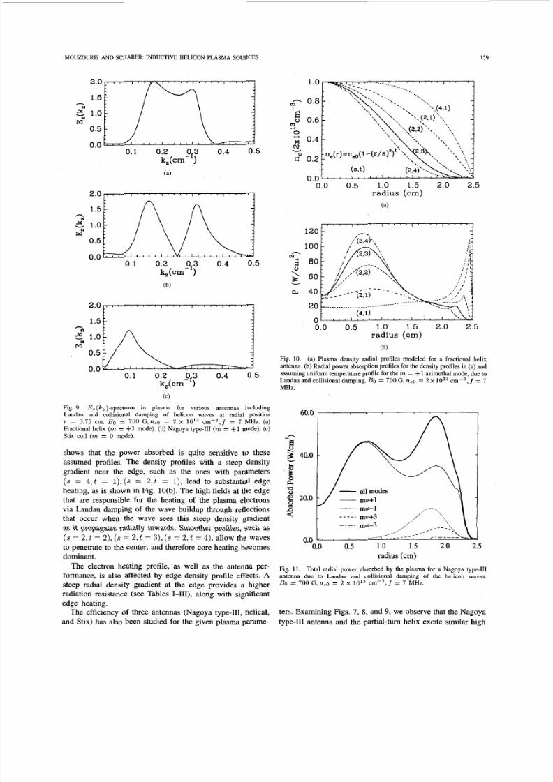
Fig. 9. E,(k,)-s pectr um in plasma for various antennas includingLandau and collisional damping of helicon waves at radial positionT = 0.75 cm . Bo = 70 0 G,ne0 = 2 x 10l3 ~ m - ~ , f 7 MHz. (a)Fractional helix ( m = +1 mode). (b) Nagoya type-I11 (m = $1 mode). (c)
Stix coil ( m = 0 mode).
shows that the power absorbed is quite sensitive to theseassumed profiles. The density profiles with a steep densitygradient near the edge, such as the ones with parameters
(s = 4 , t = l ) , s = 2 , t = l ) , ead to substantial edgeheating, as is shown in Fig. lO(b). The high fields at the edgethat are responsible for the heating of the plasma electronsvia Landau damping of the wave buildup through reflectionsthat occur when the wave sees this steep density gradient
as it propagates radially inwards. Smoother profiles, such as(s = 2 , t = 2 ) , s = 2 , t = 3) , ( s = 2 , t = 4 ) , allow the wavesto penetrate to the center, and therefore core heating becomesdominant.
The electron heating profile, as well as the antenna per-formance, is also affected by edge density profile effects. A
steep radial density gradient at the edge provides a higherradiation resistance (see Tables I-111), along with significantedge heating.
The efficiency of three antennas (Nagoya type-111, helical,and Stix) has also been studied for the given plasma parame-
1 o
m 0.8
0.62
';c 0.4
I
0
cvW6" 0.2
0. 008.0 0.5 1.0 1.5 2.0 2.5
radius (cm)
(a)
100
N E 8060
-
Wa 40
20
n0.0 0. 5 1.0 1.5 2.0 2.5
radius (cm)
(b)
Fig. 10. (a) Plasma density radial profiles modeled for a fractional helixantenna. (b) Radial power absorption profiles for the density profiles in (a) andassuming uniform temperature profile for the m = +1 azimuthal mode, due to
Landau and collisional damping. Bo = 700 G,ne0 = 2 x 10¹³ ~ m - ~ ,= 7
MHz.
60.0
h"EY3 40.0
b3n"
'I?g 20.0
s
W
c
0.00.0 0.5 1o 1.5 2.0 2.5
radius (cm)
Fig. 11. Total radial power absorbed by the plasma for a Nagoya type-I11antenna due to Landau and collisional damping of the helicon waves.Bo = 700 G, neo = 2 x l o i 3 c m P 3 , f = 7 MHz.
ters. Examining Figs. 7, 8, and 9, we observe that the Nagoya
type-I11 antenna and the partial-tum helix excite similar high
8/3/2019 Yiannis Mouzouris and John E. Scharer- Modeling of Profile Effects for Inductive Helicon Plasma Sources
http://slidepdf.com/reader/full/yiannis-mouzouris-and-john-e-scharer-modeling-of-profile-effects-for-inductive 9/9
160 IEEE TRANSACTIONS ON PLASMA SCIENCE, VOL. 24, NO. 1, FEBRUARY 1996
E,(k,)-spectra for the m = +1 azimuthal mode and have
similar radial profiles for the absorbed power, with the helical
antenna providing a higher amplitude of the power absorbed
by the electrons near the axis due to its higher radiationresistance. The Stix coil which excites a relatively loweramplitude E,(k,)-spectrum for the dominant m = 0 mode,provides a narrow but substantial radial heating profile.
We also show in Fig. 11 that the Nagoya type-III antennaexcites a number of azimuthal m modes. These higher ordermodes heat the plasma primarily near the edge. The fractionalhelix antenna excites only the m = +1 mode and reduces the
edge heating process.
IV. S U M M A RY A N D CO N CL U S IO N S
The computer code “ANTENA” was used to study andmodel helicon sources. The Nagoya type-III, the partial-tuumhelix, and the Stix coil antenna were modeled to examinethe plasma absorption profile in the lower hybrid frequencyrange. The Stix coil, which excites the m = 0 mode, heats theplasma primarily in the center. This RF coil structure shouldbe considered together with the helix and the Nagoya type-IB
helicon plasma sources. The partial-turn helix and the Nagoya
type-I11 coils excite the m = fl mode, the dominant modefor this frequency range (f = 1-30 MHz). We have included
a small fraction ( n f e / n , 5 % ) of fast electrons (T,-f,,40 eV) in the model and have shown that these fast electronsabsorb most of the RF power via Landau damping at lo w
densities (ne 5 1OI2 cmP3).The partial-tum helix is found to be more efficient in
coupling the power to the plasma than the Nagoya type-IDfor our assumed plasma profiles. This is due to its negligible
excitation of higher order (m > 3 ) modes which raise the
reactance of the source and increase the edge heating effects,higher radiation resistance of the partial-turn helix antenna,and lower quality factor, Qp, of this plasma source. Thehelix also provides an improved directionality (more launchedwave power in one direction from the source) of the k, -
spectrum.We have added a radially varying collision frequency model
[v(ne(r),e(r))]o the code to study the effects and impor-tance of the collisional and Landau damping heating mech-
anisms. The Krook collisional model shows that collisionsplay an important role in plasma production, and is thedominant electron heating mechanism at high densities (ne2
cmP3). We find that electron heating profiles are verydependent on the plasma and collisional profiles. Plasma
density profiles with a steep gradient at the edge lead tosubstantial edge heating. Smoother profiles allow the wavesto penetrate and dissipate their energy in the center, whichis comparable to experimental observations. In future work,we plan to examine the influence of a small fraction of fastelectron beams which have been observed experimentally on
helicon wave power absorption.
ACKNOWLEDGMENT
The authors would like to thank B. McVey for providinga copy of his computer code “ANTENA,” along with his
helpful comments and suggestions. We are also grateful to
M. Bettenhausen for many valuable discussions.
REFERENCES
[ l ] D. M. Manos and D. L. Flamm, Plasma Etching. A n Introduction. Ne w
York: Academic, 1989.[2] M. A. Lieben nan and R. A. Gottscho, “Design of high density plasmasources for materials processing,” University of Califomia, Berkeley,Rep. UCBERL M93/3, 1993.
[3] R. W. Boswell, “Very efficient plasma generation by whistler wavesnear the lower hvbrid freauencv,” Plasma Phvs. Controlled Fusion, vol.26(10), pp. 1147-1162, f984.-
141 A. Komori, T. Shoii. K. Mivamoto. J. Kawai, and K. K awai, “Helicon_waves and efficient plasma production,” Phys. Fluids B, vol. 3(1), pp._893-898, 1991.
151 F. F. Chen and C. D. Decker, “Electron acceleration in helicon sources,’’_P l a s m Phys. Controlled Fusion, vol. 34(4), pp. 635-640, 1992.
[6] T. Shoji, Y. Sakawa, S. Nakazawa, K. Kadota, and T. Sato, “Plasmaproduction by helicon waves,” Plasma Sources Sci. Technol., vol. 2(1 l),pp. 5-10, 19 93.
[7] R. W. Boswell, “Plasma production using a standing helicon wave,”Phys. Lett., vol. 33A(7), pp. 457 45 8, 1970.
[8] F. F. Chen, “Plasma ionization by helicon waves,” Plasma Phys.Controlled Fusion, vol. 33(11), pp. 339-364, 1991.
[9] P. K. Loew enhardt, B. D. Blackwell, R. W. Boswell, G. D. Conway, andS. M. Hamherger, “Plasma production in a toroidal heliac by helicon
waves,” Phys. Rev. Lett., vol. 67(20), pp. 2792-2794, 1991.[lo ] P. K. Loewe nhardt, B. D. Blackwell, and S. M. Hamberger, “Production
of fast electrons in a prototype heliac by helicon wav es,” Phys. Plasmas,
[ l l ] B . D. McVey, “Antena user guide,” Plasma Fusion Ctr., MIT, Rep.
PFC/RR-84-13, 1984.[12] ~, “ICRF antenna coupling theory for a cylindrically stratified
plasma,” Plasma Fusion Ctr., MIT, Rep. PFCIRR-84-12, 1984.[13] T. H. Stix, Waves in Plasmas.[14] P. L. Bhatnagar, E. P. Gross, and M. Krook, “A model for collision
processes in gases. I. Small amplitude processes in charged and neutralone-component systems,” Phys . Rev., vol. 94(3), pp. 51 1-522, 1954.
1151 B. D. Fried and S. D. Conte, The Plasma Dispersion Function. Ne w
vol. 1(4), pp. 875-880, 1994.
New Yo rk Amer. Inst. Phys., 1992.
. .York: Academic, 1961.
r161 J. C. Hosea and R. M. Sinclair, “Ion cyclotron wave generation in the-model C stellarator,” Phys. Fluids, vol.- 13(3), pp. 7011711 , 19 70.
[17] K. Watari et al., “Radio-frequency plugging of a high density plasma,”
Phys. Fluids, vol. 21(11), pp. 2076-2081, 1978.[18] I. Sudit, private communication, 1995.[I91 T. Shoji, IPPJ Annu. R ev., Nagoya Univ., Rep. 63, 1986.
Yiannis Mouzouris was born in Limassol, Cyprus,on May 7, 1969. He received the B.S. and M.S.degrees in electrical engineering from the Universityof Wisconsin, Madison, in 1992 and 1994, respec-tively. He is presently pursuing the Ph.D. degree at
the University of Wisconsin-Madison.
His research interests include modeling of high-density plasma sources for materials processing andI C W wave heating in tokamak plasmas.
John E. Scharer (M’90) received the B.S., M.S., and Ph.D. degrees inelectrical engineering from the University of Califomia, Berkeley, in plasmaphysics.
He is a Professor in the Department of Electrical and Computer Engineering,University of Wisconsin, Madison. He has spent research sabbaticals at the
CEA Fontenay-aux-Roses, France, in 1970, and at the JET tokamak at Culham,
England, in 1983. He has been active with graduate students and scientists intheoretical, computational, and experim ental research in the areas of linear and
nonlinear plasma waves, laser-formed plasma, and heating of fusion plasmasand lasers. He also teaches and carries out research in the areas of plasma RF
sources for materials processing and Cerenkov amplifiers.Dr. Scharer is a member of Tau Beta Pi, the American Physical Soc iety, and
the Center for Plasma Theory and Computation at the University of Wisconsin.