yeh hsin 690458 finaljournal
DESCRIPTION
ÂTRANSCRIPT

1
AIRS T U D I O
HSIN YEH690458
SEM 2, 2015

2

3
CONTENT
PART A. CONCEPTUALISATION A.1 DESIGN FUTURINGA.2 DESIGN COMPUTATIONA.3 COMPOSITION/GENERATIONA.4 CONCLUSIONA.5 LEARNING OUTCOMESA.6 ALGORITHMIC SKETCHES
INTRODUCTION
PART B. CRITERIA DESIGN B.1 RESEARCH FIELDB.2 CASE STUDY 1.0B.3 CASE STUDY 2.0B.4 TECHNIQUE: DEVELOPMENTB.5 TECHNIQUE: PROTOTYPEB.6 TECHNIQUE: PROPOSALB.7 LEARNING OBJECTIVES & OUTCOMESB.8 ALGORITHMIC SKETCHES
PART C. DETAILED DESIGNC.1 DESIGN CONCEPTC.2 TECTONIC ELEMENTS & PROTOTYPESC.3 FINAL DETAIL MODELC.4 LEARNING OBJECTIVES & OUTCOMES
p.6-11p.12-15p.16-19p.20p.21p.22-27
p.30-35p.36-45p.46-57p.58-75p.76-87p.88-101p.102-105p.106-115
p.118-133p.134-143p.144-153p.154-157

4
Design is my passion, as I love how existing conditions can be improved and become more desirable through creativity and de-sign. I am interested in connection between human and nature, sustainable design, and meditative space. These qualities are ev-
ident in the works I’ve done.
This journal aims to form an argument for a digitally designed architecture. Digital design is changing the field of architecture from design process through to construction. More complex structures can be easily assembled with the aid of accurate robots and machines, as done in the Dunescape by SHoP architects. New form-finding technique, such as parametric design, opens up new possibilities of architectural expression. Computer programs ex-pand the geometry and structural possibilities of architecture with its accurate calculation & modeling, and automatic generation.
My technical skills include:- fluent use of autoCAD, photoshop & indesign
- some experience in Rhino- limited skill in Grasshopper
HSIN YEH
INTRODUCTION

5
Fig.1Secret Pavilion
Studio Earth 2015by Hsin Yeh
Fig.2Natural Shelter
Studio Water 2014by Hsin Yeh
Fig.3Dunescape
MoMA 2000by SHoP Architects
http://www.archnewsnow.com

6
7
A.1 DESIGN FUTURING

8
Wendy is covered with nylon fabric treated with ti-tania nanoparticle spray, which neutralises air pol-lutants when illuminated by the sun. The spike form of Wendy maximises the surface area illuminated by the sun, therefore, maximises the capacity of clean-ing the air. The structure includes water system and fans to provide water, mists, and cool air to keep the people comfortable and entertained in hot weather.2 Wendy is an active and untraditional built forms that improves and creates an ecological environment around itself, providing shelter, comfort, and fun to its inhabitants.
Wendy is a spike form that experiments how built forms can expand into creating ecological and so-cial affects. The natural environment is damaged by unsustainable actions, which endanger the quality of living in our future. Therefore, innovative projects like Wendy have been designed to explore possible solutions to the environmental issues. The Young Ar-chitects Program at MoMA is an annual competition that challenges architects to produce an outdoor in-stallation that provides shade, seating, and water as well as addressing issues of sustainability and recy-cling.1 As the winner of the 2012 YAP, Wendy offers a new perspective that architectural projects can ac-tively improve the quality of our environment through collaboration with advanced technology.
HWKN, 2012MOMA PS1 Young Architect Program
WHAT IS WENDY?
W E N D Y
1. “Wendy by HWKN,” MoMA PS1: YAP, retrieved July 31, 2015, http://momaps1.org/yap/view/15.2. “Warm-up to Wendy!” HWKN - HOLLWICH KUSHNER, retrieved July 31, 2015, http://hwkn.com/WENDY.
Fig.1

9
that collaboration between architecture and scienceproduces solution to complex environmental prob-lems, such as air quality, and encourages others to apply advanced technology into their design. For example, the Hy-Fi by The Living (YAP 2014 win-ning project), which used biotechnology-designed bricks made of corn stalks combined with mushroom root material to construct a 100% compostable, energy-free, and carbon-free pavilion.4 The project changes the patterns of living of people by provid-ing an unusual shelter that engages people to experi-ence and relate with. Through innovative technology and performance-driven design, new alternatives for pro-active environmental architectures are opened up for more exploration.
The relationship between Wendy and its users is a friendly one. The phrases used to promote the proj-ect, such as “Have you met Wendy?”3 express the fa-miliarity of people’s attitude toward Wendy. The per-sonifying name, Wendy, makes the project relatable to its users as a friendly object. Although the project is temporary, people who have visited Wendy were offered a friendly and comfortable experience, which is a valuable achievement in architecture.
RELATIONSHIP WITH USERS
CONTRIBUTION Wendy is an unique project with uncommon archi-tectural form and innovative concept. It opens up the possibility to consider architecture as a creator, rather than a container, of environment. It also exemplifies
3. “Wendy by HWKN,” The Creatorsproject, retrieved August 1, 2015, http://thecreatorsproject.vice.com/videos/iwendyi-by-hwkn.4. “Hi-Fy,” The Living, retrieved August 1, 2015, http://thelivingnewyork.com/hy-fi.htm.
Fig.2
Fig.3
Fig.1-3 Image source: http://hwkn.com/WENDY

10
Magnus Larsson has teamed up with Soil Interac-tions Lab at UC-Davis to create a 6,000 kilometre long artificial dune to prevent the spreading of desert and provide refugee shelters. The desertification of Sahara is an urgent environmental issue that endan-gers the lives of people, animals, and plants across the area. Water conservation, soil management, agri-culture, forestry, and many other attempts have been ventured to resist desertification. The Dune offers an alternative and possibly more holistic solution by in-corporating biotechnology with advanced machine in the making of its structure.
The Dune project mimics the natural dune shape in the desert and is formed by flushing a bacteria, Bacil-lus Pasteurii, into the land, which will turn the loose sand into solid sandstone.1 By simply inserting the bacteria studied at UC-Davis, sand is solidified into a habitable structure, creating an anti-desertification by the desert itself.
WHAT DOSE DUNE DO?
Apart from soil management, the dune also allows water harvesting and thermal comfort within the structure, as there is a temperature difference be-tween the exterior and interior. This allows people to grow plants to prevent desertification, develop agri-culture, and permanently live at their homeland. All of these prevent massive migration, famine, and wars.2
1. “Sand/Stone,” BLDG/BLOG, retrieved August 1, 2015, http://bldgblog.blogspot.com.au/2009/04/sandstone.html.2. “Dune,” Magnus Larsson, retrieved August 1, 2015, http://www.magnuslarsson.com/architecture/dune.asp.3. “Sand/Stone,” BLDG/BLOG.

11
D U N EMagnus Larsson
Sahara Desert, North Africa
The Dune also relates to the surrounding environment as its shape, derived from tafoni, supports the natural process of aggregation by wind. Tafoni is, as Lars-son writes, “a cavernous rock structure that formally ties the project back to notions of aggregation and erosion,3” and it is porous with largest surface area. This means it supports water conservation and allow aggregation of sand on the structure (see Fig.2).
The Dune project is still at planning stage, and the possible construction method is injecting the bacte-ria through piles down into the sand, which is similar to building with an oversized 3D printer. 24 hours af-ter the injection, the skeleton structure of solidified sandstone is formed, and then another one week is Required for saturating the sand enough to be
Larsson’s Dune project has given a new perspective that architecture can be a physical solution to envi-ronmental and social problems. The project consid-ers more than one aspects of problems - not just the land, but also the animals, plants, and people. Lives that may otherwise be affected by desertification can be saved inside the inhabitable dunes. The soil for-mation with bacteria and the injection piles offer new ideas to the field of construction. As Larsson has stated about the Dune, “while designed to visually seduce, dune is not primarily a formal exercise, but a social, ecological, cultural one.5” Architecture of the future may be more active in responding to problems, and be more functional than formal.
Fig.1
Fig.3Fig.2
CONSTRUCTION
inhabitable.4 Although the project is bold and unre-alised, it exemplifies the possibility of building with biotechnology and digital machine. This new way of building is effective, accurate, and labour-saving.
4. “Sand/Stone,” BLDG/BLOG.5. “Magnus Larsson sculpts the Saharan desert with bacteria,” Design-boom, retrieved August 2, 2015, http://www.designboom.com/architec-ture/magnus-larsson-sculpts-the-saharan-desert-with-bacteria/.v
Fig.1-3 Image source: http://www.designboom.com/architecture/magnus-larsson-sculpts-the-saharan-des-ert-with-bacteria/

12

13
A.2 DESIGN COMPUTATION

14
Architectural design has changed since the evolvement of compu-tation in design process. Computers are capable of doing rational and more tedious tasks that require accuracy and consistency, which are difficult for humans to do when exposed to too much in-formation or worked for too long. The use of computing opens up alternative design and construction methods that applies to both communicational and technological parts of the design process.
Computers are capable of storing large amount of in-formation, which can be easily categorised by program-ming. This allows computers to search for, compare, or evaluate certain information much faster than the human minds. This is very useful in the three stages of design stated in Kalay’s “Architecture’s New Me-dia: Principles, Theories, and Methods of Comput-er-Aided Design” (2004) - problem analysis, solution synthesis, and evaluation.1 The efficiency of processing information is particularly important in evidence- and performance-oriented designing, such as the ICD/ITKE Research Pavilion of 2011 for its structural analysis.2 The design team at the University of Stuttgart facilitate design, development, and realisation within one digital system, which allows them to repeatedly read and ex-periment the load transfer of the structure.
Fig.1
Fig.2
1. Yehuda E. Kalay, Architecture’s New Media: Principles, Theories, and Methods of Computer-Aided Design (Cambridge, MA: MIT Press, 2004), 10.2. “ICD/ITKE Research Pavilion 2011,” University of Stuttgart - ICD, retrieved August 6, 2015, http://icd.uni-stuttgart.de/?p=6553.3. “Nine Elms Bridge,” Studio Roland Snooks, retrieved August 6, 2015, http://www.rolandsnooks.com/#/nine-elms/.
Fig.1-2 Image source: http://icd.uni-stuttgart.de/?p=6553

15
With the aid of computers, the accuracy and efficiency of design process has increased to produce better solutions for the complex problems of the modern world. Computer has transformed from merely an instru-ment for realising design to a medium that logically generates design. This relates to the preceding archi-tectural theory of moving from representation to using logical approach as the principle of form generation.5 Computational design re-defines architecture by providing new possibilities for form-finding and alternative approach to solving issues.
Computers also allow people to focus more on the creative part of design. The information presented by the computers, such as a 3D digital model, give designers the ability to explore different solutions easily, while the computer process technical works. The programming of computers also generated new forms that were impossible or too complicated to realise by human. This way of using calculation or rule as the principle element of form-finding is called parametric design. The structure of Nine Elms Bridge by Roland Snooks is generated by parametric program, which means an underlining rule automatically forms the design of the bridge.3 The hybrid bridge provides immersive space for pedestrian and cyclers, while the form of the bridge reflects tree branches of the surrounding landscape.
Computers can also replace human labour and per-form construction with ultimate accuracy. For exam-ple, the Gantenbein Vineyard Facade by Gramazio Kohler Architects was entirely constructed by ro-bots for the brick-layering of the facades.4 Bricks are layered in certain positions and angles in order to achieve the digitally designed pattern, which would be impossible if built by human hands. The precision of the robots saved time and labour for human, as well as creating structures that were impossible be-fore the digital age.
Fig.3
Fig.4
4. “Gantenbein Vineyard Facade, Fl酲ch, Switzerland, 2006,” Gramazio Kohler Architects, retrieved August 7, 2015, http://www.gramaziokohler.com/web/e/projekte/52.html.5. Rivka Oxman, Theories of the Digital in Architecture (London; New York: Routledge, 2014), pp. 1–10 (pp.1)
Image source: http://www.rolandsnooks.com/#/nine-elms/
Image source: http://www.gramaziokohler.com/web/e/projekte/52.html

16

17
A.3 COMPOSITION/GENERATION
18
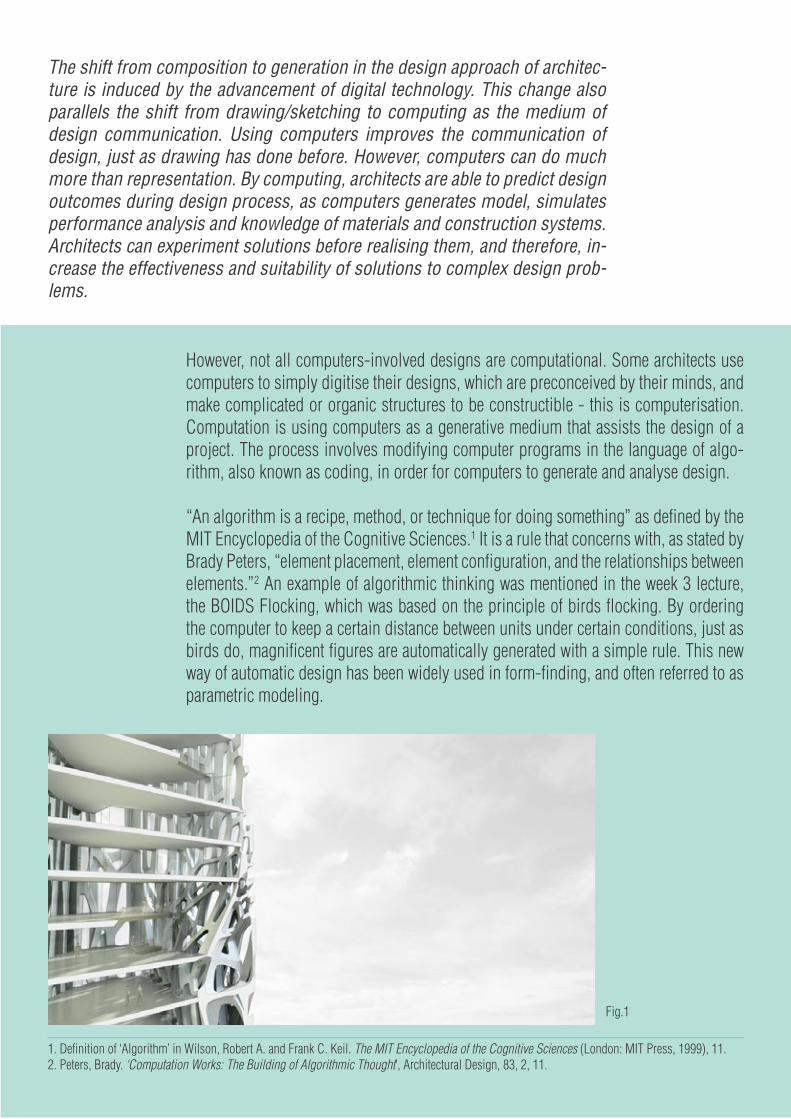
However, not all computers-involved designs are computational. Some architects use computers to simply digitise their designs, which are preconceived by their minds, and make complicated or organic structures to be constructible - this is computerisation. Computation is using computers as a generative medium that assists the design of a project. The process involves modifying computer programs in the language of algo-rithm, also known as coding, in order for computers to generate and analyse design.
“An algorithm is a recipe, method, or technique for doing something” as defined by the MIT Encyclopedia of the Cognitive Sciences.1 It is a rule that concerns with, as stated by Brady Peters, “element placement, element configuration, and the relationships between elements.”2 An example of algorithmic thinking was mentioned in the week 3 lecture, the BOIDS Flocking, which was based on the principle of birds flocking. By ordering the computer to keep a certain distance between units under certain conditions, just as birds do, magnificent figures are automatically generated with a simple rule. This new way of automatic design has been widely used in form-finding, and often referred to as parametric modeling.
The shift from composition to generation in the design approach of architec-ture is induced by the advancement of digital technology. This change also parallels the shift from drawing/sketching to computing as the medium of design communication. Using computers improves the communication of design, just as drawing has done before. However, computers can do much more than representation. By computing, architects are able to predict design outcomes during design process, as computers generates model, simulates performance analysis and knowledge of materials and construction systems. Architects can experiment solutions before realising them, and therefore, in-crease the effectiveness and suitability of solutions to complex design prob-lems.
Fig.1
1. Definition of ‘Algorithm’ in Wilson, Robert A. and Frank C. Keil. The MIT Encyclopedia of the Cognitive Sciences (London: MIT Press, 1999), 11.2. Peters, Brady. ‘Computation Works: The Building of Algorithmic Thought’, Architectural Design, 83, 2, 11.

19
The Fibrous Tower by Roland Snooks is a building with a shell facade made of series of intersecting and twisting branches. The design was first parametrically modeled to the form desired by the designer, then struc-tural details and connections with internal floors were worked through. The result is a in-situ concrete shell that provides shading, enclosed balconies, offices, and structural support of the entire building, while being vi-sually interested and unique.3
The Abu-Dhabi Performing Arts Centre by the Zaha Hadid Architects is also paramet-rically modeled. The structure is very iconic and serves as a symbol for organism. The unique and organic form of the structure is complex and creates round interior space for theatres while maintaining its aesthetic.4
Computation allows the architect to work out the building structure and performance, before the construction, which is very helpful for project such as the Fibrous Tower. Parametric modeling is able to create new forms unimaginable by human minds, as seen in both projects addressed here. However, connecting a paramet-ric structure to the physical environment, such as landscape and space arrangement, is more difficult than generating it. Computers allow changes to be made easily to the design. Yet, the new architectural forms of parametric design are for sure more complex to accommodate useful space than compositional architecture.
The shift of design approach from composition to generation relates to the change of medium for design. Parametric modeling redefine architecture as it can help designers to achieve more complex and unprece-dented design, and provides analysis and evaluation along the design process. This design approach is an alternative to composition, and with its complex nature, may be more suitable for solving complex issues.
Fig.2
Fig.3 Fig.4
3. “Fibrous Tower,” Studio Roland Snooks, retrieved August 12, 2015, http://www.rolandsnooks.com/#/fibrous-tower/.4. “Abu Dhabi Performing Arts Centre,” Zaha Hadid Architects, retrieved August 12, 2015, http://www.zaha-hadid.com/architecture/abu-dhabi-perform-ing-arts-centre/.
Fig.3-4 Image source: http://www.zaha-hadid.com/architecture/abu-dhabi-performing-arts-centre/
Fig.1-2 Image source: http://www.rolandsnooks.com/#/fibrous-tower/
20
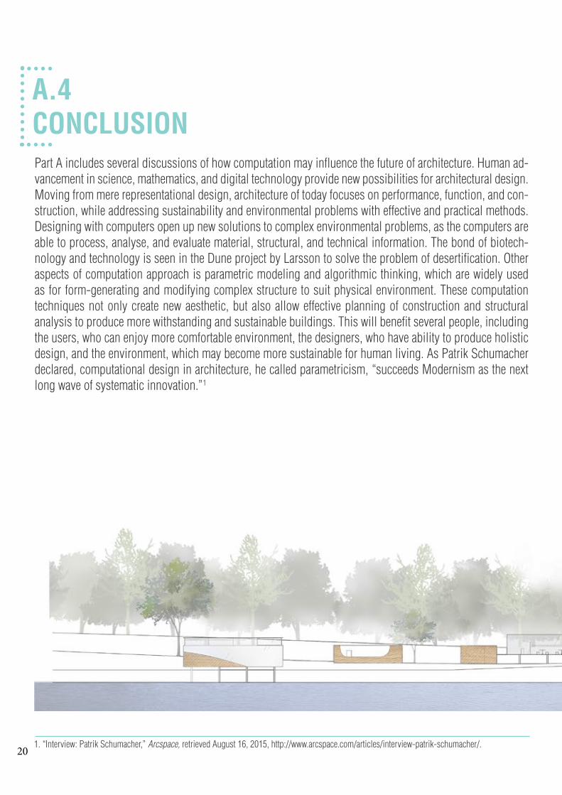
A.4CONCLUSIONPart A includes several discussions of how computation may influence the future of architecture. Human ad-vancement in science, mathematics, and digital technology provide new possibilities for architectural design. Moving from mere representational design, architecture of today focuses on performance, function, and con-struction, while addressing sustainability and environmental problems with effective and practical methods. Designing with computers open up new solutions to complex environmental problems, as the computers are able to process, analyse, and evaluate material, structural, and technical information. The bond of biotech-nology and technology is seen in the Dune project by Larsson to solve the problem of desertification. Other aspects of computation approach is parametric modeling and algorithmic thinking, which are widely used as for form-generating and modifying complex structure to suit physical environment. These computation techniques not only create new aesthetic, but also allow effective planning of construction and structural analysis to produce more withstanding and sustainable buildings. This will benefit several people, including the users, who can enjoy more comfortable environment, the designers, who have ability to produce holistic design, and the environment, which may become more sustainable for human living. As Patrik Schumacher declared, computational design in architecture, he called parametricism, “succeeds Modernism as the next long wave of systematic innovation.”1
1. “Interview: Patrik Schumacher,” Arcspace, retrieved August 16, 2015, http://www.arcspace.com/articles/interview-patrik-schumacher/.
21
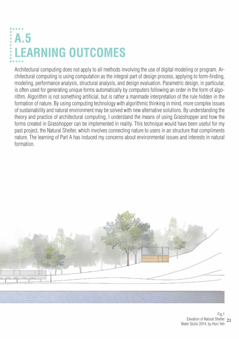
A.5LEARNING OUTCOMESArchitectural computing does not apply to all methods involving the use of digital modeling or program. Ar-chitectural computing is using computation as the integral part of design process, applying to form-finding, modeling, performance analysis, structural analysis, and design evaluation. Parametric design, in particular, is often used for generating unique forms automatically by computers following an order in the form of algo-rithm. Algorithm is not something artificial, but is rather a manmade interpretation of the rule hidden in the formation of nature. By using computing technology with algorithmic thinking in mind, more complex issues of sustainability and natural environment may be solved with new alternative solutions. By understanding the theory and practice of architectural computing, I understand the means of using Grasshopper and how the forms created in Grasshopper can be implemented in reality. This technique would have been useful for my past project, the Natural Shelter, which involves connecting nature to users in an structure that compliments nature. The learning of Part A has induced my concerns about environmental issues and interests in natural formation.
Fig.1Elevation of Natural Shelter
Water Stufio 2014, by Hsin Yeh

22

23
A.6 ALGORITHMIC SKETCHES

24
LOFTING & STAGE CAPTURE
VORONOI & POPULATE 3D

25
Taking out the polysurfaces created by voronoi 3D is useful for form finding.
Twisting the curves of a loft tube to cre-ate unexpected form.

26
TRANSFORM
A mesh is projected onto a plane as curves, and the curves are lofted to trans-form the mesh into a layered structure.

27
CURVE
A loft surface is transformed into multiple curves to create a light structure that is different to the solid original loft.

28

29
A1:-“Dune,” Magnus Larsson, retrieved August 1, 2015, http://www.magnuslarsson.com/architecture/dune.asp.-“Hi-Fy,” The Living, retrieved August 1, 2015, http://thelivingnewyork.com/hy-fi.htm.-“Magnus Larsson sculpts the Saharan desert with bacteria,” Designboom, retrieved August 2, 2015, http://www.design-boom.com/architecture/magnus-larsson-sculpts-the-saharan-desert-with-bacteria/.v-“Sand/Stone,” BLDG/BLOG, retrieved August 1, 2015, http://bldgblog.blogspot.com.au/2009/04/sandstone.html.-“Warm-up to Wendy!” HWKN - HOLLWICH KUSHNER, retrieved July 31, 2015, http://hwkn.com/WENDY.-“Wendy by HWKN,” The Creatorsproject, retrieved August 1, 2015, http://thecreatorsproject.vice.com/videos/iwendyi-by-hwkn.-“Wendy by HWKN,” MoMA PS1: YAP, retrieved July 31, 2015, http://momaps1.org/yap/view/15.
A2:-“Gantenbein Vineyard Facade, Fl酲ch, Switzerland, 2006,” Gramazio Kohler Architects, retrieved August 7, 2015, http://www.gramaziokohler.com/web/e/projekte/52.html.-“ICD/ITKE Research Pavilion 2011,” University of Stuttgart - ICD, retrieved August 6, 2015, http://icd.uni-stuttgart.de/?p=6553.-“Nine Elms Bridge,” Studio Roland Snooks, retrieved August 6, 2015, http://www.rolandsnooks.com/#/nine-elms/.-Rivka Oxman, Theories of the Digital in Architecture (London; New York: Routledge, 2014), pp. 1–10 (pp.1)-Yehuda E. Kalay, Architecture’s New Media: Principles, Theories, and Methods of Computer-Aided Design (Cambridge, MA: MIT Press, 2004), 10.
A3:-“Abu Dhabi Performing Arts Centre,” Zaha Hadid Architects, retrieved August 12, 2015, http://www.zaha-hadid.com/archi-tecture/abu-dhabi-performing-arts-centre/.-Definition of ‘Algorithm’ in Wilson, Robert A. and Frank C. Keil. The MIT Encyclopedia of the Cognitive Sciences (London: MIT Press, 1999), 11.-“Fibrous Tower,” Studio Roland Snooks, retrieved August 12, 2015, http://www.rolandsnooks.com/#/fibrous-tower/.-Peters, Brady. ‘Computation Works: The Building of Algorithmic Thought’, Architectural Design, 83, 2, 11.
A4:-“Interview: Patrik Schumacher,” Arcspace, retrieved August 16, 2015, http://www.arcspace.com/articles/interview-patr-ik-schumacher/.
PART A REFERENCES:

30

31
B.1RESEARCH FIELD

32
TESSELATION PRECEDENTSThe initial concept for the design proposal is a structure for plants to grow onto. Therefore, the field of re-search is tesselation, as this technique creates vacant spaces on a base structure that plants can potentially grow into and fill the spaces.
Throughout the research, it also becomes clear that porous effect on light-feel/thin stuctural/grid is very effective in producing a unique, delicate, and intrigued feeling to a design. This will be discussed with the three projects of tesselation I have selected for this section.
The project I chose to iterate for B.2 Case Study 1 is the Voussoir Cloud as the caternary lines are inter-esting for form and structural design. The technique of tesselation, using lightweight and porous material, from all three projects also influenced the design of my proposal.

33
The Voussoir Cloud is made of 3-dimensional wedged petals, which connect to one another to form 5 columns. Extending from each column, the petals become larger and eventually con-struct several vaults at the top of the structure. The design team used digital hanging chain models and form finding technique to refine the profile lines into pure caternaries. The petals represented ‘voussoirs’, traditional wedge-shape stone used to construct arch, but reverse the heavy impression of voussoirs by using folded thin wood laminates as the material. The Vossoir Cloud demonstrates the method to create archi-tectural structural with light material and porous elements.
IwamotoScott
V O U S S O I R C L O U D

34
Transformer is a lightweight, layered, and light-re-sponsive structure that has active-shading function with the potential to be incorporated into building envelope. The quad-shape, polystyrene petals are attached to the lightweight, but rigid polycarbonate strucutal grid. Sensors on the petals interpret light data and deliver message to the motors to alter the petals in closing or opening motions to achieve optimised shading. Transformer is an example of lightweight, transformable, and porous structure that can provide efficient shading, while being structurally stable.
I.M.A.D.E
T R A N S F O R M E R

35
POLY.lux is constructed a number of thin flat elements, which created three tunnels hanging from the roof. The form naturally occurred by pull of gravity force. There are more than 1400 bat-tery-powered LED lights attached to the pieces, and lighten up the structure. The POLY.lux is a design that aims to provide sensory experience to passer-bys with its thin material, porous de-sign, and delicate lighting.
SOFTlab
P O L Y . l u x

36

37
B.2CASE STUDY 1

38
SPECIES 1
Offset of anchor points at bottomZ force
Offset of anchor points at bottomZ force
Offset of anchor points at bottomZ force
Offset of anchor points at bottomZ force

39
SPECIES 2
Specie 1 ---> Specie 2- Base curve is changed from rectangle to circle.- Lofting curves are offset - Anchor points changed
Offset of circle curveZ forceRest length
Offset of circle curveZ forceRest length
Offset of circle curveZ forceRest length
Offset of circle curveZ forceRest length
Offset of circle curveZ forceRest length
Offset of circle curveZ forceRest length

40
SPECIES 3
Specie 2 ---> Specie 3- Number of points increase- Change of anchor points
Offset of circle curveZ forceRest lengthNumber of points
Offset of circle curveZ forceRest lengthNumber of points
Offset of circle curveZ forceRest lengthNumber of points
Offset of circle curveZ forceRest lengthNumber of points
Offset of circle curveZ forceRest lengthNumber of points
Offset of circle curveZ forceRest lengthNumber of points
41
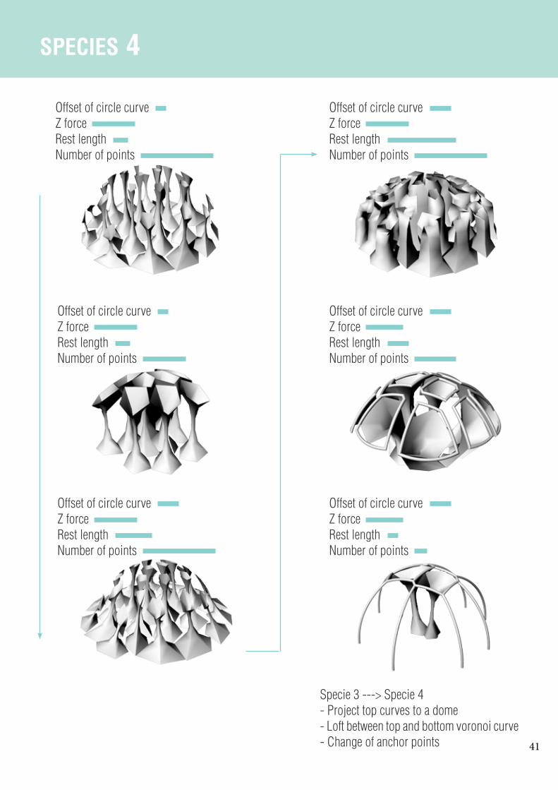
SPECIES 4
Specie 3 ---> Specie 4- Project top curves to a dome- Loft between top and bottom voronoi curve- Change of anchor points
Offset of circle curveZ forceRest lengthNumber of points
Offset of circle curveZ forceRest lengthNumber of points
Offset of circle curveZ forceRest lengthNumber of points
Offset of circle curveZ forceRest lengthNumber of points
Offset of circle curveZ forceRest lengthNumber of points
Offset of circle curveZ forceRest lengthNumber of points
42
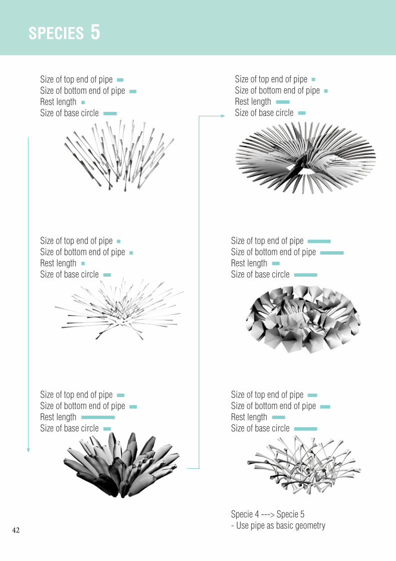
SPECIES 5
Size of top end of pipeSize of bottom end of pipeRest lengthSize of base circle
Specie 4 ---> Specie 5- Use pipe as basic geometry
Size of top end of pipeSize of bottom end of pipeRest lengthSize of base circle
Size of top end of pipeSize of bottom end of pipeRest lengthSize of base circle
Size of top end of pipeSize of bottom end of pipeRest lengthSize of base circle
Size of top end of pipeSize of bottom end of pipeRest lengthSize of base circle
Size of top end of pipeSize of bottom end of pipeRest lengthSize of base circle

43
SPECIES 6
Specie 6- continue from Specie 4
Size of top voronoi cellSize of bottom voronoi cellRest lengthNumber of points
Size of top voronoi cellSize of bottom voronoi cellRest lengthNumber of points
Size of top voronoi cellSize of bottom voronoi cellRest lengthNumber of points

44
SELECTION CRITERIAThe proposal for my design is a structure for plants to grow onto it and create a unique form that combines the structure and the plants’ body. When creating the iterations, I was trying to achieve forms that are easy for plants to grow into. I also experimented with forms that are possible to become a shelter for people. Therefore, the criteria for selecting successful iterations of this exercise is a form that is porous / web-like, continuous, and creates shelter space.
Four outcomes from the iterations are selected and extrapolated...

45
SELECTED OUTCOMES
This structure has a distorted web structure that forms good base for plants to grow and fill up the vacant spaces. The base is circular, and when some pillars are added under, the circular edge create some shelter from sunlight.
The web-like structure has a unique form and very porous. This gives plants many possible routes to grow. There are not much shleter pro-vided, but the form is a good inspiration for fur-ther development.
This structure has a lighter appearance than the others as it is supported by several thin pipes. These pipes provide routes for plants to connect at the two main structures in the middle. There is no shelter, but the connections between each part is interesting for further development.
These mushroom-like tubes have expanding tops, which provide some shelter from sunlight. There are spaces in between each tube, so peo-ple can walk between and get close to plants growing on the tubes. Web pattern can be later implemented onto the tubes’ surface to make them suitable for plants growth.

46

47
B.3CASE STUDY 2

48
Freeland Buck, 2008Vienna, Austria
T E C H N I C O L O U R B L O O M
Fig. 1archinect.com
www.freelandbuck.com1. “Technicolour Bloom,” Freeland Buck, retrieved 18 September 2015, http://www.freelandbuck.com/Projects/TechnicolorBloom.2. Ibid.
MIDPOINT MIDPOINT
MIDPOINT
1/4 1/4
1/4 3/4
3/43/4
Diagram

49Fig. 2
Technicolour Bloom uses parametrical design and standard fabrication technique to produce a dou-bly-curved architectural form. 1400 unique pieces of flat plywood panels, which are partly colour-sprayed, are used for constructing this kaleidoscopic installation at Silver Gallery, Vienna.1 There are two layers of exact pattern, one on top of the other, to create a three-dimensional sense of the pattern.
The project intends to give new possibility to topological surface by incorporating traditional architectural parameters (structure, aperture, and material), to the doubly-curved geometry.2
The use of parametric design enables the complex pattern to be implemented onto the curved surface easily. The pattern, although appears complex, is based on a simple rule using conventional drawing parameter, as shown in the diagram below. The project is successful in showing new possibility of what parametric design can achieve. The collaboration between computation and construction also successfully create a mythical experience for people when interacting with Technicolour Bloom.
50
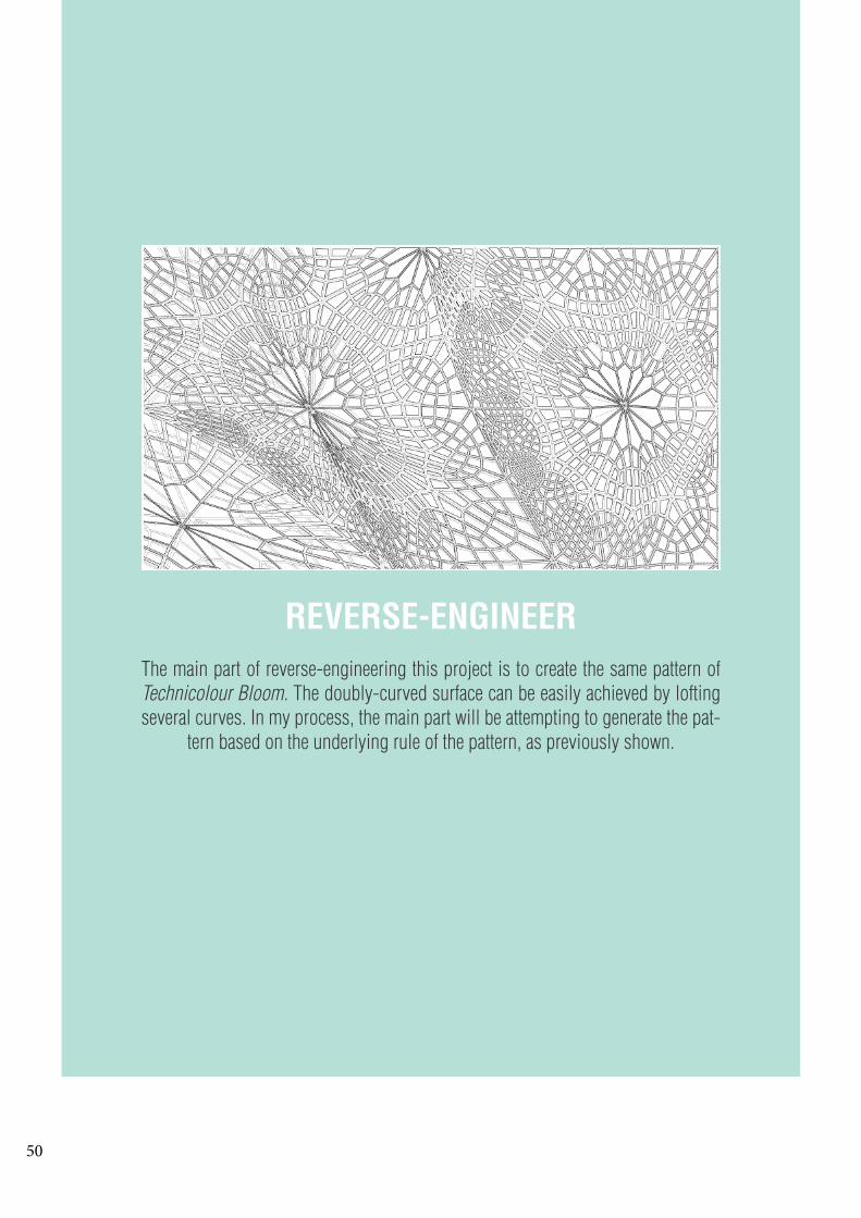
REVERSE-ENGINEERThe main part of reverse-engineering this project is to create the same pattern of Technicolour Bloom. The doubly-curved surface can be easily achieved by lofting several curves. In my process, the main part will be attempting to generate the pat-
tern based on the underlying rule of the pattern, as previously shown.

51
1. Lofting several curves for the bottom layer.
2. Lofting several curves for the upper layer.
3. Using Lunchbox to create tri-angles on a rectangle surface, and then create quadrangles inside the triangles.
4. Using Lunchbox to create tri-angles on a rectangle surface, and then use VORONOI to generate similar effect as the quadragles.
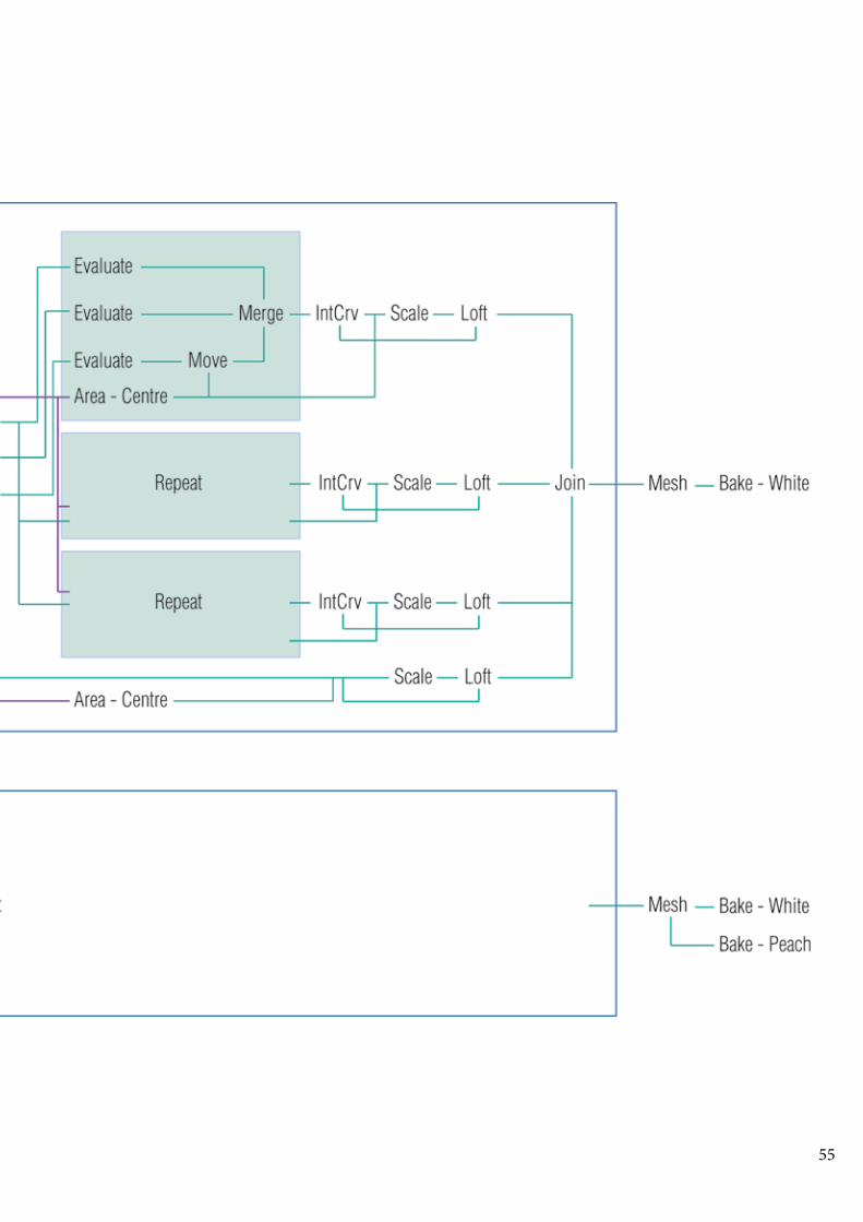
5. Using Lunchbox to create trian-gles and quadrangles inside the triangles on the surface. Using LIST ITEM to select each of the three lines that make up the tri-angles. Use EVALUATE to select points at 1/4 and 3/4 on each line. Use AREA to figure out the cen-tre point at each triangle, and use MERGE and INTCRV to link cen-tre with other two points to draw desired curve. Repeat this three times.GET THE PATTERN !!

52
7. Change the base surface of the pattern in step 5 to the loft surface in step 2. This attempt successful-ly incorporates the pattern to the curved surface.
6. PROJECT the pattern in step 5 to loft surface in step 2 in the at-tempt to incorporate the pattern to the surface. The result was distort-ed and some curves are missing.
8. OFFSET each curve a few distance away from the original, and LOFT the offsetted and original curves to transform the pattern’s lines into flat frames. This is repeated four times, separately for each group of curves - each line of the triangles and the line of the quadrangles. Both upper and bottom layers gone through this process.

53
9. Bake the lower layer with peach material colour, and then copy it by offsetting a little bit upward and make this copied layer white. This is to achieve the effect of spraying inner side of the lower layer peach, while the outer side remains white, as done in the construction of the project.
10. Bake the upper layer with white material.

54
PROCESS DIAGRAM
55

56
Fig. 3www.christofgaggl.com
This outcome can be further de-veloped by changing the basic surface to a flatter topographical surface or a sphere to extend the ability to project pattern gener-ated by using DELAUNAUY or VORONOI, which is restricted to planar surface, onto the more regular surface.

57
The outcome depicts the essence of the original project, and explores the effect created by repeating a simple pattern on two overlpping layers.
However, the outcome pattern could have been more accurate to the original pattern if the hexa-gon can be further divided into 12 segments rather than just 6 segments. The method to achieve this was not figured out, as every attempt would restrict, in later stage, the ability to draw curves between 1/4 points, 3/4 points and centre points of each triangle. Another difference is that the lower layer of the original project is in white and peach on either faces, but in the reverse-en-gineered outcome, two layers are baked, one in white and one in peach, and placed closely to create similar effect. This may be resolved by extruding the lower layer in rhino to create a solid and render each face in white and peach.
The reverse-engineered outcome is successful in creating pattern using the same underlying rule as the original pattern. The outcome also achieve the aim of the original project, which is to give new possibility to topological surface by incorporating traditional architectural parameters (structure, aperture, and material). Parametric design has enables the ability for designers to create forms and pattern that would be too complicated to produce or even imagined in the past.
OUTCOME & ORIGINAL

58

59
B.4TECHNIQUE: DEVELOPMENT

60
SPECIES 1
Triangular panel - U: 8, V: 15Curve group 1 - Crv1: 0.75, Crv2: 0.25Curve group 2 - Crv1: 0.25, Crv3: 0.75Curve group 3 - Crv2: 0.75, Crv3: 0.25IntCrv Degree: 1Curve offset: 0.8Hexagon curve offset: 0.9Quadrangle subdivide: 1Amplitude - B: 0.39
Triangular panel - U: 6, V: 10Curve group 1 - Crv1: 0.5, Crv2: 0.5Curve group 2 - Crv1: 0.5, Crv3: 0.5Curve group 3 - Crv2: 0.5, Crv3: 0.5IntCrv Degree: 3Curve offset: 0.8Hexagon curve offset: 0.9Quadrangle subdivide: 1Amplitude - B: 0.39
Triangular panel - U: 6, V: 10Curve group 1 - Crv1: 0.2, Crv2: 0.8Curve group 2 - Crv1: 0.8, Crv3: 0.2Curve group 3 - Crv2: 0.2, Crv3: 0.8IntCrv Degree: 3Curve offset: 0.9Hexagon curve offset: 0.9Quadrangle subdivide: 2Amplitude - B: 2
Triangular panel - U: 6, V: 10Curve group 1 - Crv1: 0.75, Crv2: 0.25Curve group 2 - Crv1: 0.25, Crv3: 0.75Curve group 3 - Crv2: 0.75, Crv3: 0.25IntCrv Degree: 3Curve offset: 0.9Hexagon curve offset: 0.9Quadrangle subdivide: 2Amplitude - B: 2

61
Triangular panel - U: 8, V: 12Curve group 1 - Crv1: 1, Crv2: 0.5Curve group 2 - Crv1: 0.5, Crv3: 1Curve group 3 - Crv2: 1, Crv3: 0.5IntCrv Degree: 3Curve offset: 0.9Hexagon curve offset: 0.9Quadrangle subdivide: 2Amplitude - B: 3
Triangular panel - U: 8, V: 12Curve group 1 - Crv1: 0.7, Crv2: 0.3Curve group 2 - Crv1: 0.3, Crv3: 0.7Curve group 3 - Crv2: 0.7, Crv3: 0.3IntCrv Degree: 3Curve pipe radius: 1Hexagon curve offset: 0.95Quadrangle subdivide: 1Amplitude - B: 1.2
Triangular panel - U: 8, V: 12Curve group 1 - Crv1: 0.3, Crv2: 0.3Curve group 2 - Crv1: 0.3, Crv3: 0.4Curve group 3 - Crv2: 0.3, Crv3: 0.4IntCrv Degree: 3Curve offset: 0.9Quadrangle subdivide: 1Amplitude - B: 1.2

62
SPECIES 2
Triangular panel - U: 10, V: 10Triangular frame scale: 0.95Curve group 1 - Crv1: 0.7, Crv2: 0.3Curve group 2 - Crv1: 0.7, Crv3: 0.5Curve group 3 - Crv2: 0.3, Crv3: 0.5IntCrv Degree: 3Curve offset: 0.5Amplitude - B: 0.97
Triangular panel - U: 10, V: 10Quadrangle frame scale: 0.7Curve group 1 - Crv1: 1, Crv2: 1Curve group 2 - Crv1: 0, Crv3: 0Curve group 3 - Crv2: 0, Crv3: 1IntCrv Degree: 1Pipe radius: 1.5Amplitude - B: 0.97
Triangular panel - U: 10, V: 10Quadrangle frame scale: 0.7, N:2Curve group 1 - Crv1: 1, Crv2: 1Curve group 2 - Crv1: 0, Crv3: 0Curve group 3 - Crv2: 0, Crv3: 1IntCrv Degree: 1Pipe radius: 1.5Amplitude - B: 0.97
Triangular panel - U: 10, V: 10Quadrangle frame scale: 0.85Curve group 1 - Crv1: 1, Crv2: 1Curve group 2 - Crv1: 0, Crv3: 0Curve group 3 - Crv2: 0, Crv3: 1IntCrv Degree: 3Pipe radius: 1Amplitude - B: 0.97

63
Triangular panel - U: 10, V: 10Quadrangle frame scale: 0.85Curve group 1 - Crv1: 1, Crv2: 1Curve group 2 - Crv1: 0, Crv3: 0Curve group 3 - Crv2: 0, Crv3: 1IntCrv Degree: 1Pipe radius: 1Amplitude - B: 0.97
Triangular panel - U: 10, V: 10Quadrangle frame scale: 0.8Curve group 1 - Crv1: 1, Crv3: 1Curve group 2 - Crv1: 0, Crv3: 0Curve group 3 - Crv2: 0, Crv3: 1Curve group 4 - Crv3: 0, Crv4: 1IntCrv Degree: 3Pipe radius: 1Amplitude - B: 2
Triangular panel - U: 10, V: 10Quadrangle frame scale: 0.8Curve group 1 - Crv1: 0, Crv3: 0Curve group 2 - Crv1: 1, Crv3: 0Curve group 3 - Crv2: 0, Crv3: 1Curve group 4 - Crv3: 0, Crv4: 1IntCrv Degree: 3Pipe radius: 1Amplitude - B: 1

64
SPECIES 3
Triangular panel - U: 3, V: 5Quadrangle N: 2Curve group 1 - Crv1: 0.5, Crv2: 0, Crv3: 0Curve group 2 - Crv1: 0, Crv2: 0, Crv4: 0.5Curve group 3 - Crv2: 0, Crv3: 0.5, Crv4:0IntCrv Degree: 3Scale of curves: 0.97
Triangular panel - U: 3, V: 5Quadrangle N: 2Curve group 1 - Crv1: 0.2, Crv2: 0.4, Crv3: 0Curve group 2 - Crv1: 0.2, Crv2: 0.4, Crv4: 0Curve group 3 - Crv2: 1, Crv3: 1, Crv4:1IntCrv Degree: 3Curve pipe radius: 1
Triangular panel - U: 3, V: 5Quadrangle N: 2Curve group 1 - Crv1: 1, Crv2: 0.5, Crv3: 1Curve group 2 - Crv1: 0, Crv2: 1, Crv4: 0Curve group 3 - Crv2: 0, Crv3: 1, Crv4:1IntCrv Degree: 3Curve pipe radius: 1
Triangular panel - U: 3, V: 5Quadrangle N: 2Curve group 1 - Crv1: 0.5, Crv2: 0, Crv3: 1Curve group 2 - Crv1: 0.5, Crv2: 0, Crv4: 1Curve group 3 - Crv2: 0, Crv3: 1, Crv4:1IntCrv Degree: 3Curve pipe radius: 1

65
Triangular panel - U: 3, V: 5Quadrangle N: 2Curve group 1 - Crv1: 0.5, Crv2: 0.5, Crv3: 1Curve group 2 - Crv1: 0.5, Crv2: 0, Crv4: 1Curve group 3 - Crv2: 1, Crv3: 1, Crv4:1Curve group 4 - Crv1: 1, Crv2: 0.5, Crv4:1IntCrv Degree: 3Curve frame scale: 0.99
Triangular panel - U: 3, V: 5Quadrangle N: 2Curve group 1 - Crv1: 0.8, Crv2: 0.5, Crv3: 1Curve group 2 - Crv1: 0.5, Crv3: 1, Crv4: 0.5Curve group 3 - Crv2: 0.5, Crv3: 1, Crv4: 0.5Curve group 4 - Crv1: 0.9, Crv2: 0.5, Crv4:1IntCrv Degree: 1Pipe radius: 1
Triangular panel - U: 3, V: 5Quadrangle N: 2Curve group 1 - Crv1: 0.8, Crv2: 0.5, Crv3: 1Curve group 2 - Crv1: 0, Crv3: 0, Crv4: 0Curve group 3 - Crv2: 1, Crv3: 0.5, Crv4: 0.5Curve group 4 - Crv1: 0.9, Crv2: 0.5, Crv4:1IntCrv Degree: 1Pipe radius: 1

66
SPECIES 4
Hexagon cells - U: 4, V:3Curve group 1 - Crv1: 0.5, Crv2: 0, Crv3: 1Curve group 2 - Crv1: 0, Crv3: 1, Crv4: 1Curve group 3 - Crv2: 1, Crv3: 1, Crv4: 1Curve group 4 - Crv1: 1, Crv2: 1, Crv4:1IntCrv Degree: 1Pipe radius: 1
Hexagon cells - U: 4, V:3Curve group 1 - Crv1: 0.7, Crv2: 1, Crv3: 1Curve group 3 - Crv2: 0.5, Crv3: 0, Crv4: 0.7Curve group 4 - Crv1: 0, Crv2: 0, Crv4: 0IntCrv Degree: 3Curve frame scale: 0.97
Hexagon cells - U: 4, V:3Curve group 1 - Crv1: 0, Crv2: 1, Crv5: 1Curve group 3 - Crv2: 0.5, Crv3: 0, Crv4: 0.7Curve group 4 - Crv1: 0, Crv2: 0, Crv4: 0.7IntCrv Degree: 1Curve frame scale: 0.97
Hexagon cells - U: 4, V:3Curve group 1 - Crv1: 0, Crv2: 1, Crv4: 0.7, Crv5: 0Curve group 3 - Crv1: 0, Crv3: 0, Crv4: 0, Crv5: 0.5Curve group 4 - Crv1: 0, Crv2: 0, Crv4: 0.9IntCrv Degree: 3Curve frame scale: 0.97

67
Hexagon cells - U: 4, V:3Curve group 1 - Crv1: 0, Crv2: 0.4, Crv3: 1, Crv4: 1, Crv5: 1Curve group 4 - Crv1: 1, Crv2: 1IntCrv Degree: 1Curve frame scale: 0.97
Hexagon cells - U: 4, V:3Curve group 1 - Crv1: 0.5, Crv2: 0, Crv3: 0.7, Crv5: 0IntCrv Degree: 3Curve frame scale: 0.97
Hexagon cells - U: 4, V:3Curve group 1 - Crv3: 0, Crv4: 0, Crv5: 1IntCrv Degree: 1Curve frame scale: 0.97

68
SPECIES 5
Triangular panel - U: 5, V: 5Quadrangle N: 1Curve group 1 - Crv1: 0.75, Crv2: 0.25, Crv3: 1IntCrv Degree: 1Pipe radius: 1
Triangular panel - U: 5, V: 5Quadrangle N: 1Curve group 1 - Crv1: 0.75, Crv2: 0.25, Crv3: 1IntCrv Degree: 1Pipe radius: 1Quadrangle curve pipe radius: 1
Triangular panel - U: 5, V: 5Quadrangle N: 1Curve group 1 - Crv1: 0, Crv2: 0, Crv3: 0.5IntCrv Degree: 1Pipe radius: 1
Triangular panel - U: 5, V: 5Quadrangle N: 1Curve group 1 - Crv1: 0, Crv2: 0, Crv3: 0.5IntCrv Degree: 1Pipe radius: 1Quandrangle pipe radius: 1

69
Triangular panel - U: 2, V: 2Quadrangle N: 2Curve group 1 - Crv1: 0, Crv2: 0, Crv3: 0.5Curve group 1 - Crv1: 0.5, Crv2: 0.5, Crv3: 0.5IntCrv Degree: 1Pipe radius: 1Quadrangle pipe radius: 1
Triangular panel - U: 2, V: 2Quadrangle N: 1Curve group 1 - Crv1: 1, Crv2: 0.8, Crv3: 1Curve group 1 - Crv1: 0, Crv2: 0, Crv3: 0.5Arc for curvePipe radius: 1
Triangular panel - U: 2, V: 2Quadrangle N: 1Curve group 1 - Crv1: 0, Crv2: 0, Crv3: 0Curve group 1 - Crv1: 1, Crv2: 0, Crv3: 1Arc for curvePipe radius: 1
The selection criteria of successful iterations from these iterations is the plasticity of the pattern. This indicates that the rule behind the pattern formation has more potential of producing complex pattern than other iterations.
The selected iterations are Species 2.1, Specices 2.5, and Species 5.6, which are marked by frames.
SELECTION CRITERIA

70
SPECIES 6
Curve group 1 - Crv1: 0, Crv2: 1, amp B:0.97 ->IntCrvCurve group 2 - Crv1: 0.5, Crv3: 0.5, amp B:0.97->IntCrvCurve group 3 - Crv2: 0.5, Crv3: 0.5, amp B:0.97->IntCrvEval: 0.7TriA - U:10, V:10
Species 6 is based on Species 2.1.
Curve group 1 - Crv1: 0.5, Crv2: 0.5, amp B:0.97 ->IntCrvCurve group 2 - Crv1: 0.5, Crv3: 0.5, amp B:0.97->IntCrvCurve group 3 - Crv2: 0.5, Crv3: 0.5, amp B:0.97->IntCrvCurve group 4 - Crv1: 0.3, Crv2: 0.7, amp B:0.4 ->IntCrvCurve group 5 - Crv1: 0.7, Crv3: 0.3, amp B:0.4->IntCrvCurve group 6 - Crv2: 0.3, Crv3: 0.7, amp B:0.4->IntCrvEval: 0.7TriA - U:10, V:10
Curve group 1 - Crv1: 0.5, Crv2: 0.5, amp B:0.8 ->IntCrvCurve group 2 - Crv1: 0.5, Crv3: 0.5, amp B:0.8->IntCrvCurve group 3 - Crv2: 0.5, Crv3: 0.5, amp B:0.8->IntCrvCurve group 4 - Crv1: 0.5, Crv2: 0.5, amp B:0.4 ->IntCrvCurve group 5 - Crv1: 0.5, Crv3: 0.5, amp B:0.4->IntCrvCurve group 6 - Crv2: 0.5, Crv3: 0.5, amp B:0.4->IntCrvEval: 0.5TriA - U:10, V:10

71
Curve group 1 - Crv1: 0.5, Crv2: 0.5, amp B:1.7 ->IntCrvCurve group 2 - Crv1: 0.5, Crv3: 0.5, amp B:1.7->IntCrvCurve group 3 - Crv2: 0.5, Crv3: 0.5, amp B:1.7->IntCrvCurve group 4 - Crv1: 0.5, Crv2: 0.5, amp B: 2->IntCrvCurve group 5 - Crv1: 0.5, Crv3: 0.5, amp B: 2->IntCrvCurve group 6 - Crv2: 0.5, Crv3: 0.5, amp B: 2->IntCrvEval: 0.5TriA - U:10, V:10
Curve group 1 - Crv1: 0.7, Crv2: 0.3, amp B:1.2 ->IntCrvCurve group 2 - Crv1: 0.3, Crv3: 0.7, amp B:1.2->IntCrvCurve group 3 - Crv2: 0.7, Crv3: 0.3, amp B:1.2->IntCrvCurve group 4 - Crv1: 0.3, Crv2: 0.7, amp B:1.5->IntCrvCurve group 5 - Crv1: 0.7, Crv3: 0.3, amp B:1.5->IntCrvCurve group 6 - Crv2: 0.3, Crv3: 0.7, amp B:1.5->IntCrvEval: 0.5TriA - U:10, V:10

72
SPECIES 7
Curve group 1 - Crv1: 1, Crv2: 0.3, amp B:0.97 ->IntCrvCurve group 2 - Crv1: 0, Crv3: 0.3, amp B:0.97->IntCrvCurve group 3 - Crv2: 0.7, Crv3: 0.7, amp B:0.97->IntCrvTriA - U:10, V:10
Species 7 is based on Species 2.5.
Curve group 1 - Crv1: 0.6, Crv2: 0.6, amp B:0.97 ->IntCrvCurve group 2 - Crv1: 0.4, Crv3: 0.4, amp B:0.97->IntCrvCurve group 3 - Crv2: 0.4, Crv3: 0.6, amp B:0.97->IntCrvCurve group 4 - Crv1: 0.7, Crv2: 0.3, amp B:0.97 ->IntCrvCurve group 5 - Crv1: 0.3, Crv3: 0.3, amp B:0.97->IntCrvCurve group 6 - Crv2: 0.7, Crv3: 0.7, amp B:0.97->IntCrvTriA - U:10, V:10
Curve group 1 - Crv1: 0.6, Crv2: 0.6, amp B:0.97 ->IntCrvCurve group 2 - Crv1: 0.4, Crv3: 0.4, amp B:0.97->IntCrvCurve group 3 - Crv2: 0.4, Crv3: 0.6, amp B:0.97->IntCrvCurve group 4 - Crv1: 0.9, Crv2: 0.1, amp B:0.97 ->IntCrvCurve group 5 - Crv1: 0.1, Crv3: 0.1, amp B:0.97->IntCrvCurve group 6 - Crv2: 0.9, Crv3: 0.9, amp B:0.97->IntCrvTriA - U:10, V:10

73
Curve group 1 - Crv1: 0.5, Crv2: 0.5, amp B:0.97 ->IntCrvCurve group 2 - Crv1: 0, Crv3: 0.5, amp B:0.97->IntCrvCurve group 3 - Crv2: 0, Crv3: 0, amp B:0.97->IntCrvCurve group 4 - Crv1: 0.7, Crv2: 0.3, amp B:0.97 ->IntCrvCurve group 5 - Crv1: 0.3, Crv3: 0.3, amp B:0.97->IntCrvCurve group 6 - Crv2: 0.7, Crv3: 0.7, amp B:0.97->IntCrvTriA - U:10, V:10
Curve group 1 - Crv1: 0.5, Crv2: 0.5, amp B:0.97 ->IntCrvCurve group 2 - Crv1: 0, Crv3: 0.5, amp B:0.97->IntCrvCurve group 3 - Crv2: 0, Crv3: 0, amp B:0.97->IntCrvCurve group 4 - Crv1: 0.2, Crv2: 0.8, amp B:0.97 ->IntCrvCurve group 5 - Crv1: 0.3, Crv3: 0.2, amp B:0.97->IntCrvCurve group 6 - Crv2: 0.7, Crv3: 0.8, amp B:0.97->IntCrvTriA - U:10, V:10

74
SPECIES 8
Curve group 1 - Crv1: 0.5, Crv2: 0.8, Crv3: 0 ->ArcCurve group 2 - Crv1: 0, Crv2: 1, Crv3: 0.1 ->IntCrv D = 3Pipe radius: 1TriC - U:2, V:2Quad N:1
Species 8 is based on Species 5.6.
Curve group 1 - Crv1: 0.4, Crv2: 0.6, Crv3: 0 ->ArcCurve group 2 - Crv1: 0.8, Crv2: 0.2, Crv3: 0 ->ArcPipe radius: 1TriC - U:2, V:2Quad N:1
Curve group 1 - Crv1: 0.3, Crv2: 0.7, Crv3: 0 ->ArcCurve group 2 - Crv1: 0.9, Crv2: 0.1, Crv3: 0 ->ArcCurve group 3 - Crv1: 0.6, Crv2: 0.4, Crv3: 0 ->ArcPipe radius: 1TriC - U:2, V:2Quad N:1

75
Curve group 1 - Crv1: 0.9, Crv2: 0.1, Crv3: 1 ->ArcCurve group 2 - Crv1: 0.8, Crv2: 0.2, Crv3: 1->ArcCurve group 3 - Crv1: 0.7, Crv2: 0.3, Crv3: 1->ArcCurve group 4 - Crv1: 0.6, Crv2: 0.4, Crv3: 1->ArcPipe radius: 1TriC - U:2, V:2Quad N:1
Curve group 2 - Crv1: 0, Crv2: 0, Crv3: 0->ArcCurve group 3 - Crv1: 0, Crv2: 1, Crv3: 1->ArcPipe radius: 1TriC - U:2, V:2Quad N:1

76

77
B.5TECHNIQUE: PROTOTYPES

78
PROTOTYPE RESEARCH
Fig.1
ICD/ITKE Research Pavilion 2014-2015, ICD/ITKEThe pavilion is digitally designed based on the analysis of the web building process of diving bell water spider (Agy-roneda Aquatica).1 The underlying rule of the water spider’s web proves to be material efficient and stable. The pavilion is fabricated by stiffening a flexible pnuematic formwork with carbon-fiber reinforcement from the inside.2
Fig. 2
1. “ICD/ITKE Research Pavilion 2014-2015,” University Stuttgart, retrieved 18 September 2015, http://icd.uni-stuttgart.de/?p=12965.2. Ibid.
http://icd.uni-stuttgart.de/?p=12965

79
Fig.3
The Hive UK Pavilion Milan 2015,BDP & Wolfgang ButtressThe Hive is part of the UK Pavilion at Expo Milan 2015. The connecting rods of the structure is no thicker than a finger to create a very delicate sense.3 The structure was based on the construction of bee hive, which is able to carry the weight.4 The rods are interlocked with each other and LED lights are attached.
Fig.4
3. “Expo milan 2015: inside the hive with wolfgang buttress at the UK pavilion,” Designboom, retieved 18 September, http://www.designboom.com:8080/architecture/uk-pavilion-expo-milan-2015-wolfgang-buttress-interview-05-05-2015/.4. Ibid.
www.designboom.com

80
JOINTS RESEARCH
Sqirl Cafe Canopy 2012, Freeland BuckThe canopy are made of individual curved strips, which are only hung from its outer edge and connect-ed with each other at inner edge.5 This creates a single, interconnected structure that can be hung to create a canopy.
5. “Sqirl Cafe Canopy,” Freeland Buck, retrieved 18 September 2015, http://www.freelandbuck.com/Projects/SqirlCanopy
Fig. 5
Fig. 6 http://www.freelandbuck.com/Projects/SqirlCanopy

81
Possible Mediums Kite 2014, Freeland BuckThe project is a 48 cubic foot space frame was rein-vented using the tetrahedral kite concept developed by Alexander Graham Bell. The frame is supported by light material that connects with each other at the joint shown in Fig. 8. The frame is a 3-dimensional volume that project 2-dimensional image as it turns in air.6
Fig. 7
Fig. 8
6. “Possible Mediums Kite,“ Freeland Buck, retieved 18 September 2015, http://www.freelandbuck.com/Projects/PossibleMediumsKite
http://www.freelandbuck.com/Projects/PossibleMediumsKite

82
JOINTS RESEARCH
F13bLUR.ma, Callie Friesenhahn & Elijah WoodThe project is a canopy providing shadow and inco-porated with the surrounding trees. The canoopy has a freeform, which is divided into hexagons and con-structed by a repetitive structural system. Hexagon glass panels are connected by steel plates with each other and supported to ground by steel studs.7
7. “F13bLUR-ma,“ Behance, retrieved 30 September 2015, https://www.behance.net/gallery/13606197/F13bLUR-ma

83
Qualitative Industrialization Gen_Ex.ll, Christopher IrelandThe project is a canopy surrounding several trees, as well as providing allocated space for each tree. The structure was first based on curves that define the fundamental forms of the canopy, which are a series of profile lines. Then, grids are developed over those basic lines guiding the form.8
8. ”Qualitative Industrialization: Gen_Ex. II,” Behance, retrieved 30 September 2015, https://www.behance.net/gallery/7800737/Qualitative-Indus-trialization-Gen_Ex-II

84
PROTOYPING
Incorporate pattern from reverse-engineering onto the surface developed from case study 1
Lofting the curves with their offsetted parts.

85
Lofting the curves with their offsetted parts.
Baking the frames created from loft.

86
Extract one part of the prototype, and MAKE2D in rhino to generate flat drawing of the pattern.
Separate each triangle frame and prepare each piece ready for laser cutter.
PRODUCING JOINTS

87
When the prototype is pushed in, the struc-ture transformed according to the force.
When the prototype is pressed from the top, the structure becomes flat. Hence the material and structure make the prototype flexible to change.
The lightweight and porous structure from B.1 Research on tessela-tion designs have informed the final decision to produce a thin, rigid, and porous prototype for my proposal

88

89
B.6TECHNIQUE: PROPOSAL

90
SITE: COLLINGWOOD CHILDREN’S FARM
CARPARK
ABBOTTSFORD CONVENT
FARM CAFE

91
SITE:- people visit the farm to be close to nature- the Farm Cafe is a social space where most people go and stay- users are mostly family with children and adult groups
CHOSEN SITE: THE OPEN AREA AT THE BACK OF THE FARM CAFE
REASON:- the cafe is a social space that encourage people to engage with the design proposal- the cafe provide reasons of people staying longer: food, shelter, seats
DESIGN BRIEF:- a web structure for plants to grow into to emphasise the power and
beauty of plant growth
92
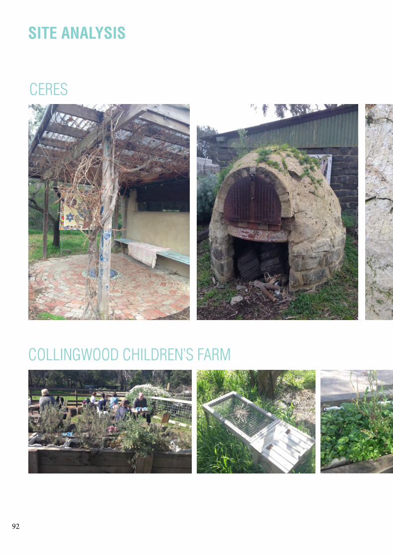
SITE ANALYSIS
CERES
COLLINGWOOD CHILDREN’S FARM

93
- power of plant growth, such as climb-ing a post, breaking concrete structure
INSPIRATIONS
- existing planting at site, a variety of planting methods suitable to different types of plants
DESIGN CONCEPT:- a web structure for plants to grow into to emphasise the pow-er and beauty of plant growth- provide shelter for people- a playful space for children, even adult to get in and enjoy

94

95
The design proposal is a network structure that allows plants to grow into its form, as well as create shelter for the people at the Collingwood Children’s Farm. It is to be situated at the open area of the Farm Cafe. Its function is providing space for plant growth within a human environment, potentially for the cafe staff to grow edible plants for their menu, and pro-vide shelter and entertainment for visitors.
TO INTERACTTO SEETO TOUCHSHELTERPLANT GROWTHNETWORK
P L A N T - N E T

96
HUMAN ENGAGEMENT
People can get into the structure and be really close with plants, to see and experience the beauty of plant growth, which the Children’s Farm emphasised.

97
Shelter are provided by the structure, and interesting shad-ows may be created under sunlight.

98
RETHINKING AFTER FEEDBACKS
The initial design concept of my proposal is to create a network structure that provides both shelter and space for plant growth. The main objective of the concept is to emphasise the power/beauty of plant growth, which was inspired by the natural surrounding of the site at the Collingwood Children’s Farm and CERES. The design is a canopy or a pavilion that aims to create opportunities for people to view, touch, and learn about the plants. This will be achieved by designing the pavilion to provide shelter and shading to draw people’s attention, as well as making the network and structure of the design in a way that signify the characteristics of plant growth.
1) What are the form and pattern of the net-work informed by?A: The emphasis of the design is power/beauty of plant growth. Therefore, I decide the form and pat-tern will be inspired by the way plant climbs and tangles the material. The form needs to be of reasonable height for plant to grow to. The pattern can be informed by the natural form of plants or a desir-able pattern that creates interesting shading effect.
THE SITEThe site at the Farm Cafe of the Collingwood’s Chil-dren’s Farm is located in an environment largely oc-cupied by human-implemented planting. There are human, animal, and vegetation activities, which are brought together by the farm’s function - a place for people to interact with and learn about animals, plants, and the ecosystem. The design proposal will evolve into part of the site by showcasing plant growth in a different way. Hence, providing opportunity and stim-ulus for people-nature interaction.
Drawing from the feedback of interim presentation, there are several questions about the design proposal that require answers.
How will the design evolve with the site, the clients, and the people.
THE CLIENTSThe clients of the design proposal are the plants to be grew onto the structure, and the Farm Cafe. Idealy, the intention is to grow edible plants that are useful to the cafe’s menu. This way, the design not only showcases plants, but also provides space for the cafe’s ingre-dients. Alternatively, the clients could be other plants that the Collingwood’s Children’s Farm already or wish es to plant.
2) How will the structure react to plant growth? And, what material is able to achieve this?A: The prototype 01 in part B.5 has an interesting flexibility due to the etched, instead of cut, edges between each face. This flexibility can highlight the strength of plant growth by reacting to the twisting, bending, and pulling forces of plants. The material to achieve this effect needs to be light and plastic, so it can be easily modified without fracture.

99
THE CLIENTSThe clients of the design proposal are the plants to be grew onto the structure, and the Farm Cafe. Idealy, the intention is to grow edible plants that are useful to the cafe’s menu. This way, the design not only showcases plants, but also provides space for the cafe’s ingre-dients. Alternatively, the clients could be other plants that the Collingwood’s Children’s Farm already or wish es to plant.
3) How to ensure and predict the effectiveness of shading?A: In order to ensure the pavilion/canopy has effective and intriguing shading, a method of predicting and analysing shading is required. The tutors from interim presentation have suggested using Ladybug, a plug-in for Grasshopper, to produce solar analysis of the design. Also, the effect of shading can be predicted by using render in Rhino.
2) How will the structure react to plant growth? And, what material is able to achieve this?A: The prototype 01 in part B.5 has an interesting flexibility due to the etched, instead of cut, edges between each face. This flexibility can highlight the strength of plant growth by reacting to the twisting, bending, and pulling forces of plants. The material to achieve this effect needs to be light and plastic, so it can be easily modified without fracture.
PEOPLE
PAVILION
PLANT
THE PEOPLEThe people who will encounter the design are those visiting the farm and eating at the cafe. The pavilion aims to bring plants and people together in order to create interaction between them. Therefore, the pavil-ion may evolve into an installation for entertainment for adults and children, a shelter from the sun, and a interesting structure to be viewed at.

100

101

102
103
B.7LEARNING OBJECTIVES &
OUTCOMES

104
Objective 1The brief of my design proposal: a structure suitable for plant growth, has provided direction and limitation to my decision when using parametric tool, Grasshopper, for form finding in the iter-ations of Case Study 1 & 2. I was manily focusing on creating web-like, porous, or expandable form that will be useful inspirations to my design proposal.
Objective 2The techniques I learned from the tutorial videos for Grasshopper have increased my ability to produce more interesting forms using parametric tools in com-plex/simple logic. For B.2, B.3, & B.4, I was able to understand the logic of the scripts and alter them accordingly.
Objective 5The open-ended brief of studio Air al-lowed me to draft my brief according to my own interest and research. B.1 Research Field provided the foundation of my design brief, and through out the iterations and reverse-engineering, I was able to narrow down the outcomes I in-tended to achieve.
Objective 6After understanding the tools and appli-cation of parametric design, I was able to analyse the concepts, techniques, and design of contemporary architectural projects. This enables the critical analy-sis in B.1 Research Field and selection of a project for B.3 Case Study 2.
B.1 B.2 B.3

105
Objective 3I learned about the knowledge of using Rhino, Grasshopper, and various 3D me-dia, such as the laser cutter, card cutter, and 3D printer, through the exercise of iterations, reverse-engineering, and pro-totyping. This skills widen the possible design solutions I can use for my project.
Objective 4In my understanding, the name of this studio, AIR, encompass meanings of flu-id form, transformable structure, and at-mosphere of surroundings. The paramet-ric tool, Grasshopper, has enabled me to achieve these qualities in form-finding, as the logic of the script can be easily changed to suit various requirements and limitations of a brief.
Objective 7I have developed foundational knowl-edge about computational geometry, data structures and types of program-ming through the process of iterations and reverse-engineering. I needed to re-search for solution when I faced trouble with the programming. Websites, such as food4rhino and Grasshopper3d, are useful to find plug-in and solutions in parametric programming.
Objective 8Now that I have learned the advantages, disadvantages and area of application of parametric programming, I have im-proved my capability to achieve certain desired forms through parametric pro-gramming. This capability was what makes my B.2, B.3, B.4, and B.5 possi-ble.
B.3 B.5 B.4

106

107
B.8ALGORITHMIC SKETCHES

108
GEODESIC ON SPHERE

109
VORONOI LINES FROM 3D OBJECT
110
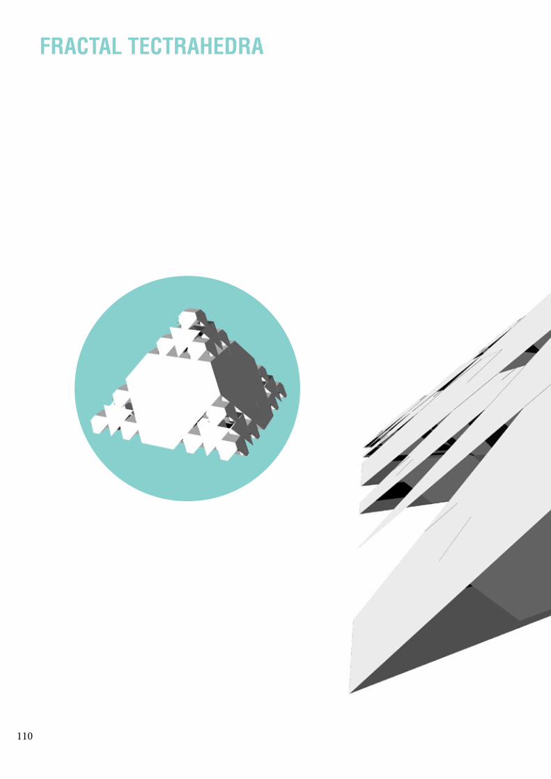
FRACTAL TECTRAHEDRA

111

112
EVALUATING FIELDS

113
GRAPHING SECTION PROFILES

114
GRAPHING SECTION PROFILES BAKE

115

116

117
B3:-“Technicolour Bloom,” Freeland Buck, retrieved 18 September 2015, http://www.freelandbuck.com/Projects/Technicolor-Bloom.
B5:-“Expo milan 2015: inside the hive with wolfgang buttress at the UK pavilion,” Designboom, retieved 18 September, http://www.designboom.com:8080/architecture/uk-pavilion-expo-milan-2015-wolfgang-buttress-interview-05-05-2015/.-“ICD/ITKE Research Pavilion 2014-2015,” University Stuttgart, retrieved 18 September 2015, http://icd.uni-stuttgart.de/?p=12965.-“Possible Mediums Kite,“ Freeland Buck, retieved 18 September 2015, http://www.freelandbuck.com/Projects/Possible-MediumsKite-“Sqirl Cafe Canopy,” Freeland Buck, retrieved 18 September 2015, http://www.freelandbuck.com/Projects/SqirlCanopy-“F13bLUR-ma,“ Behance, retrieved 30 September 2015, https://www.behance.net/gallery/13606197/F13bLUR-ma-”Qualitative Industrialization: Gen_Ex. II,” Behance, retrieved 30 September 2015, https://www.behance.net/gal-lery/7800737/Qualitative-Industrialization-Gen_Ex-II
PART B REFERENCES:

118

119
C.1DESIGN CONCEPT

120
COLLABORATIONOF FOUR PROJECTS
FEATURES:
FEEDBACKS:
- Complex pattern created by repetition of simple ge-ometry.- Script knowledge of generating pattern by drawing curves through specific points.- Script knowledge of form finding with Kangaroo.- Concept: through a network structure, to express the power and beauty of plant growth and engage people with it.
- To have a clear reason of what the pattern and form of the network are inspired from.- To think about a more suitable material, and develop a construction method.- To test shading effect with analysing software, such as Ladybug.
PLANT-NET HSIN YEH BE.DIGHT YULIANA WIDJAJA
FEATURES:
FEEDBACKS:
- Strong design concept to redesign the fishway at the Dights Falls.- Script knowledge of generating form with sphere collides.- Concept: to enhance the appearance of the fishway and encourage more human engagement with it.
- To have a controal over the form finding technique to get a desirable form.- To think about how the functions of the existing fish-way is incoporated into the new design.

121
HEXAGON JAMES GIBBS NET TOWER TINGRU LIU
FEATURES:
FEEDBACKS:
- Based off of a Canopy Project in Toronto, created to imitate nature and the process of walking through a forest.- Script knowledge of generating pattern by listing points on hexagons and drawing through the points.- Concept: a series of shelters designed in modular parts and placed in certain way so nature would grow around and into them.
- To have a stronger and more specific concept.- To develop more depth into designing.
FEATURES:
FEEDBACKS:
- an interactive structure suspended above water & ground.- with simple but strong network structure capable of carrying weight.- Script knowledge of creating pattern with weaver-bird.- light-weight material (Lycra) makes it possible for the installation to suspend on surrounding trees.
- To have a more specific reason on the choice of site.- To provide testing of the strength and pressure of the structure with software.

122
FINALISEDCONCEPT
MERRI CREEK
DIGHTS FALLS
The site and concept of our finalised project is based on Yuliana’s project, which is to redesign the existing fishway at the Dights Falls.
The form finding technique of her design was em-ployed. The pattern-gen-erating technique of Hsin and James is applied.
The concept of engaging people with the site’s water and vegetation is derived from projects of Hsin, Jams, and Tingru.
The existing fishway was built in 2012 to enable fish migration from down-stream to upstream.
A timber structure was built to provide water to the Mel-bourne Flour Milling Company.
The timber weir was broken thus require new structure.
The original timber piles were capped by concrete, replac-ing the timber deck.
1940 19681895
COMBINED IDEA
THE FISHWAY

123
TO CREATE A NEW FISHWAY BASED ON THE ENGINEERING METHOD OF THE EXIST-ING FISHWAY.
THE NEW DESIGN WILL HAVE A MORE AESTHETIC & ORGANIC APPEARANCE THAT TRANS-FORM THE FISHWAY INTO AN ATTRACTION FOR PEOPLE TO VIEW AND EXPERIENCE.
THE NEW DESIGN WILL ALSO INCORPORATE THE FUNCTIONS OF THE EXISTING ONE INTO ITS NEW STRUCTURE.
Melbourne Water constructed a rock fishway to allow fish to move around the weir.
The rock fishway was replaced by a more effective vertical slot fishway.
1993 2012 2015
?
CONCEPT
“Dights Falls weir and fishway construction (Yarra River, Abbotsford)”, Melbourne Water, retrieved on 30 October 2015, http://www.melbournewater.com.au/whatwedo/projectsaroundmelbourne/pages/dights-falls-weir-and-fishway-construction.aspx
EXISTING

124
RESIDENTIAL
ROAD
ATTRACTIONS WATER
VEGETATION
MERRI CREEK YARRA RIVER
UPSTREAMDOWNSTREAM
ABBOTSFORD CONVENT
COLLINGWOODCHILDREN’SFARM
DIGHTS FALL
HUMAN ACCESS
CAPITAL CITY TRAIL
N
SITE &CLIENT
AUSTRALIAN GRAYLING are a native migratory fish that live in coastal rivers and streams from as North as Grose River in NSW to Hopkins River in western Victoria and in Tasmania.
They sprawn in freshwater and the hatched larvae drift downstream to-ward saltwater or the sea. After six months, the young Grayling need to migrate back to freshwater in the upstream to complete their life cycle.
THE AIM OF THE FISHWAY is to assist the Australian Grayling migrate back to upstream at the Dights Falls, where the weir is a barrier to fish migration.
THE AIM OF OUR PROJECT is to provide the same func-tion of the existing fishway, but with a more comprehensive and attrac-tive structure that: 1) Incorporate fishway function within the design of the new form, 2) enhance the human expereince at the Dights Falls as a tourist attraction.
PEOPLE come to the region of the site for recreation at various lo-cations: the Abbotsford Convent anf the Collingwood Children Farm. The Dights Fall is also accessible by the Capital City Trail. The fishway provides opportunity for people to learn about the migration of Aus-tralian Grayling. People can also enjoy viewing the complex and curly form of the new fishway.

125
RESIDENTIAL
ROAD
ATTRACTIONS WATER
VEGETATION
MERRI CREEK YARRA RIVER
UPSTREAMDOWNSTREAM
ABBOTSFORD CONVENT
COLLINGWOODCHILDREN’SFARM
DIGHTS FALL
HUMAN ACCESS
CAPITAL CITY TRAIL
N

126
CONSTRUCTION DIAGRAM
TECHNIQUEDIAGRAM

127

128
FORM FINDING
The outline of a section of the Yarra River at the Dights Falls is used as a starting point to find a suitable contour for our design.
A final form is selected because of its complex, yet clear and distinct curls.
ITERATIONS
OUTLINE
PARAMETERS:- Anchor points- Radius of sphere collides- Strength of sphere collides

129
The outline is altered to follow the topograpphy of the site, so the design merges with the site contour.
A final form is selected because of its complex, yet clear and distinct curls.

130
FINAL DESIGN
SITE MODELViewing from south-east
TO INTERACT
TO SEE
TO TOUCH
AESTHETIC
ENGAGING HUMAN
COMPLEX PATTERN

131
SITE MODELViewing from south-east
HUMAN PERSPECTIVEViewing from north-west

132
HOW IT WORKS
FISH PERSPECTIVE
SECTION

133
WATER PIPESWITH HOLES
CURVED COMPARTMENTS
ROCKS TO ADD SURFACE ROUGHNESS
TO ADD WALL ROUGHNESS TO
SLOW DOWN WATER

134

135
C.2TECTONIC ELEMENTS &
PROTOTYPES

136
PROTOTYPE DEVELOPMENT
THE PROTOTYPE DEMONSTRATES THE CURLED PART ON THE TOP EDGE OF THE FISHWAY.

137
PROTOTYPE IS TRANSFORMED INTO MESH OF TRIANGULAR FACES WITH PATTERN APPLIED ON THEM.
THE PATTERN IS CREATED BY DRAWING CURVES THROUGH THE SELECTED POINTS.

138
PROTOTYPE CONSTRUCTION
THE OUTER EDGE OF THE PROTOTYPE IS BLACK AND THE INNER PART IS IN WHITE TO EMPHASISE THE CURVED FORM OF ITS EDGES.
139
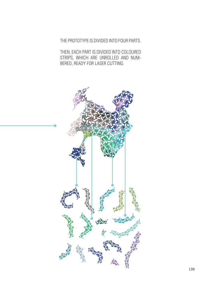
THE PROTOTYPE IS DIVIDED INTO FOUR PARTS.
THEN, EACH PART IS DIVIDED INTO COLOURED STRIPS, WHICH ARE UNROLLED AND NUM-BERED, READY FOR LASER CUTTING.

140
TESTING JOINTS
STAPLES RIVETS
JOIN
TSAP
PEAR
ANCE

141
RIVETS EYELETS

142
CONSTRUCTINGPROTOTYPE
PROCESS
Each strip is joined to the other by riveting the holes on the joining pieces of each triangle.
The strips are numbered, and each of them connects to another strip in a specific way. During the process, we need to relate the nimbered strups to the strips in the rhino file to find the exact way they join.

143
The most succesful joints were rivets because they are stronger than staples and eyelets. Rivets also hold the strips together tighter than eyelets. This creates a more resolved model.
RIVETS
The strips join in small groups, and then each group is connected in the end to create the final model.

144

145
C.3FINAL DETAIL MODEL

146
SITE MODEL

147
SECTIONMODEL

148
DETAILMODEL

149
A POSSIBLE WEARPIECE ON BODY

150
DETAILMODEL in site

151
THE MODEL BLENDS INTO NATURE

152
DETAILMODEL in site

153

154

155
C.4LEARNING OBJECTIVES

156

157
FEEDBACKSTHE FEEDBACKS FROM THE FINAL PRESENTATION WERE:
- TO PRODUCE CLEARER DIAGRAMS TO EXPLAIN HOW OUR DESIGN IS MORE EFFECTIVE OR DESIRABLE THAN THE EXISTING FISHWAY.
- TO RETHINK THE MATERIAL OF CONSTRUCTION IN REALITY
- TO MAKE SURE OUR DESIGN INCORPORATES THE FUNCTIONS OF THE EXISTING FISHWAY
LEARNING OBJECTIVESThe design project is about an architecture that is functional and site specific. It is more about addressing issues and responding to the existing conditions of the site in relation to specific clients, such as plants, fishes, water, and other animals. The complexity of this project requires the use of parametric tool to generate certain forms, which can be generate with parameters of the site, such as water level, distances, and sun path.
For the final project, I was able to use parametric tools to generate form that is suitable to the specific water depth and topography of the site. I also used the knowledge of scripting pattern from part B to create complex pattern, which mimics water waves, and applied it to the final project.
REFERENCES“Dights Falls weir and fishway construction (Yarra River, Abbotsford)”, Melbourne Water, retrieved on 30 October 2015, http://www.melbournewater.com.au/whatwedo/projectsaroundmelbourne/pages/dights-falls-weir-and-fishway-construction.aspx