yasnac i80m - milwaukee makerspacewiki.milwaukeemakerspace.org/_media/equipment/mitsuura_ra1f... ·...
TRANSCRIPT

YASNAC i80MCNC SYSTEM FOR MACHINING CENTERS
APPENDIX
Before initial operation read these instructions thoroughly, and retain for future reference
YASUAWA

This appendix is a supplement to the YASNAC i80M Instruction
Manual, Connection Manual and Service Manual.
Detailed data necessary for supplementary explanations
of the list of alarms, parameters and settings that appear in
these manuals are included in this supplement.
Use this manual as supplementary data for those who are
engaged in designing NC machine tools and in operation and
maintenance of machines.
— C O N T E N T S —
1 . A D D R E S S C H A R A C T E R """"" """".. "... ".""" .""" O.""o--oo-"---o ---oo-"-o"o"--" "-""" .-""" --oo- """ 3
2 . F U N C T I O N C H A R A C T E R . . . . . . . . . . . . . . . . . . . . . . . . . . . . . . . . . . . . . . . . . . . . . . . . . . . . . . . . . . . . . . . . . . . . . 4
3 . T A P E C O D E . . . . . . . . . . . . . . . . . . . . . . . . . . . . . . . . . . . . . . . . . . . . . . . . . . . . . . . . . . . . . . . . . . . . . . . . . . . . . . . . . . . . . . . . . .5
4. TAPE FORMAT C"""" "" OO"O. C"" O"""" "" C."." "--"" -o--" ""-----o ---"" """" ---oo-----o-""" ""o" -"-o" ""o-"-"-" 7
5 . D A T A S E T T I N G R A N G E """"" """. "... O". OO"""""""O".". "" C"". "". "". """". """"" "". C. C"""" o-"" --oooo 8
6 . C O M M A N D V A L U E R A N G E ." O"""" """"" -""". ""-" OO. "". """"" S"--4"--""oooooo "----"-"--""-"-"-- 9
7 . A L A R M . . . . . . . . . . . . . . . . . . . . . . . . . . . . . . . . . . . . . . . . . . . . . . . . . . . . . . . . . . . . . . . . . . . . . . . . . . . . . . . . . . . . . . . . . . . . . . . . 11
7.1 NUMBERING OF THE ALARM NUMBERS . . . . . . . . . . . . . . . . ..$ . . . . . . . . . . . . . . . . ..O. 11
7.2 ALARM NUMBER TABLE ."""" ."""" ."""" """"" "" OS.. -."... O"""" """"" .OOI". "O" O"""" """o" o-o-o 12
8. G CODE OO""""C"" ..".. C. 000"""0"""""0"" ".""" "". """"" """"" "".." oo"--"-o--<o----+ "---" "o-o--" "oo-" o"'--""" 119
9. P A R A M E T E R "." O".. "".".. " . . .. OOO.COOO""""S"" "OO""O""".CCCCC ."""" oo------"o ---------" ----- o---oo "-" 121
9.1 PARAMETER NUMBER LIST . ..o.. ooc..oocc . . ..."""""""""""""""""""""""""""""""""""""""" 121
9.2 PARAMETER NUMBER TABLE .o . . . . . . ..c . . ..o . . . ..-o" """""""""""""""""""""""""""""" 131
1 0 . S T A N D A R D lNPUT/OUTPUT D I A G N O S I S . . . . . . . . . . . . . . . . . . . . . . . . . . . . . . . . . . . . . . . 319
10.1 STANDARD INPUT/OUTPUT DIAGNOSIS NUMBER LIST ““””””.””.”” 319
10.2 INPLTT SIGNAL PLC+NC . . . . . . . . . . . . . . . . . . . . . . . . . . . . . . . . . . . . . . . . . . . . . . . . . . . . . . . . . . . . . . . 32010.3 OUTPUT SIGNAL NC+PLC . . . . . . . . . . . . . . . ,.. .$,,,,,,,,.. ,, .,.,.,,..,,,, . . . . . . . . . . . . . . . 328
–2–

1. ADDRESS CHARACTER
Address
A
B
c
D
E
F
G
H
I
J
K
L
M
N
o
P
Q
R
s
T
u
v—
w
x
Y
z
B: Basic0: Option
Meaning i Classi f icat ion
Rotating axis around the axis parallel to the X–axis o
Rotating axis around the axis parallel to the Y–axis o
Rotating axis around the axis parallel to the Z–axis o—
Tool radius offset number B, O
Microprogram characters and canned cycle feed o
Cutting feedrate B
Set–up function B, O
Tool offset number B
X coordinate of circular center, radius when cutting circle B, O
Y coordinate of circular center, cutting allowance when cutting B, Ocircle
Z coordinate of circular center B
Number of repetitions B, O
Auxiliary function B
Sequence number B
Program number B
Dwell time, specifications for G1O tool offset numberSpecification of program number at a subprogram, and sequence
Bo
number
Depth of cut and amount of shift of canned cycle o
Radius at point R of canned cycleSpecifications for G1O tool offset amount
O, B
Spindle function B
Tool function B
Additional axis parallel to the X– axis o
Additional axis parallel to the Y–axis o
Additional axis parallel to the Z–axis and new initial point of ocanned cycle
X–axis coordinate value and dwell time B
Y– axis coordinate value B
Z–axis coordinate value B
–3–

2. FUNCTION CHARACTER
E 1A Code
Blank
BS
Tab
C R
SP
ER
Uc
LC
2–4–5 Bit
2–4–7 Bit
+
o t o 9
a t o z
I
Del
.
Parametersetting
*
=
[
1
0
$
@
?
Note:
ISO Code Meaning Remarks
NulError in significant section of EIA and disregardedin 1S0
BS Disregard
HT Disregard
LF/NL End of block (EOB)
CR Disregard
SP Space
% Rewind stop
Up shift
Down shift
( Control out (Comments start) EIA is a
) Control in (Comments end) special code
+ Disregard, microprogram operator— Minus sign, microprogram operator
o to9 Numbers
Ato Z Address code
/ Optional block skipMicroprogram character
DEL Disregard (Including All Mark)
. Decimal point
# ] Sharp (Variable) I* Asterisk (Multiplication operator)—— I Equal sign I
( Large left parenthesis
1 I Large right ~arenthesis I EIA is a
For microprogram comments special code
$ For microprogram comments
@ For microprogram comments
? For microprogram comments
For microprogram comments
1. All codes other than the above in the significant information section become errors.2. Information sandwiched between the control out and control in codes become meaningless.3. Tape code (EIA/ISO) can be specified with setting #0004 DO.
–4–

3. TAPE CODE
EIA DataCtiaracter
1S0 Data8 ‘1 6 5 4 0 3 2 1 8 7 6 5 4 0 3 2 1
0 0 0 0 0 0
0 0 1 0 0 0 0 00 0 2 0 0 0 0 0
0 0 0 0 3 0 0 0 0 00 0 4 0 0 0 0 0
0 0 0 0 5 0 0 0 0 00 0 0 0 6 0 0 0 0 0
0 0 0 0 7 0 0 0 0 0 0 00 8 0 0 0 0 0
0 0 0 0 9 010 0 0 0
0 0 0 0 a A o 0 0I
o 0 0 0 b B o 0 00 0 0 0 0 0 c c o 0 0 0 00 0 0 0 d D o 0 00 0 0 0 0 0 e E o 0 0 00 , 0 0 0 0 0 f F o 0 0 0 00 0 0 0 0 0 g G o 0 0 0 00 0 0 0 h H o 0 00 0 0 0 0 0 i I o 0 0 0 00 0 0 0 0 j J o 0 0 0 0
10] Iol Iol lo\ k K 101 ]Olol 10]0(-) o 0 1 0 1 T. ( - l o 101010- .
0 0 0 0 m M o 0 0 0 00 0 0 0 n N o 0 0 0 00 0 0 0 0 0 0 0 0 0 0 0 00 0 0 0 0 0 P P o 0 00 0 0 0 Q Q o 0 0 0 00 0 0 0 r R o 0 0 0 0
0 0 0 0 s s o 0 0 0 00 0 0 0 t T o 0 0 0 00 0 0 0 u u o 0 0 0 0
0 0 0 0 v v o 0 0 0 0
0 0 0 0 w w o 0 0 0 0 0 00 0 0 0 0 0 x x o 0 0 0 0
!Iolololol Y Y Iol lo\olol o
0 010 101 z z o Io lolo 101I 1 I
o Blank NUL o
0 0 0 0 BS o 0 0
–5–

3. TAPE CODE (Cent’d)
EIA Data 1S0 DataCharacter
8 7 6 5 4 0 3 2 1 8 7 6 5 4 0 3 2 10 0 0 0 0 0 Tab HT o 0 0
0 0 CR L F / N L o 0 0— CR o 0 0 0 0
0 0 S P o 0 0
0 0 0 0 ER % o 0 0 0 00 0 0 0 0 0 Uc —
o 0 0 0 0 0 LC —
o 0 0 — ( o 0 0
0 0 0 . ) o 0 0 0 0
0 0 0 0 + o 0 0 0 0
0 0 — o 0 0 0 0
0 0 0 0 0 0 0 0 0 0
0 0 0 0 / o 0 0 0 0 0 0
0 0 0 0 0 0 0 0 Del D E L o 0 0 0 0 0 0 0 0
0 0 0 0 0 0 0 0 0 All Mark o 0 0 0 0 0 0 0 0
Note 2 # o 0 0 0 0
0 0 0 0 * o 0 0 0 0
0 0 0 0 —. 0 0 0 0 0 0 0
0 0 0 0 [ o 0 0 0 0 0 0
0 0 0 0 1 0 0 0 0 0 0 0
0 0 0 0 $ 0 0 0
0 0 0 0 0 0 @ o 0 00 o 0 0 0 0 ? o 0 0 0 0 0 0
0 0 0 0 . 0 0 0 0 0
0 0 0 0 0 0 0 0 0
t value for parameter #4108 o 0 0 0 0
Set value for parameter #4109 . 0 0 0
Set value for parameter #4144 < 0 0 0 0 0
Set value for parameter #4145 > 0 0 0 0 0 0 0
Set value for parameter #4146 o 0 0 0 0 0 0
w00
00
Se
Note :1. The EIAcode of character ‘#–?” is generally not defined. Theabove codeis
used in this system as a temporary code.2. The EIAcode of character “#” can be specified with parameter #4100.
–6–

4. TAPE FORMAT
No.
1
2
3
4
5
6
9
10
11
12
13
14
15
16
17
Output (mm) Output (in. )Address B : Basic
Input (mm) Input (in. ) Input (mm) Input (in. ) 0 : ‘Ption,
Program number I 05 I 05 IB
Sequence number N5 N5 B—.G Function G3 G3 B
Coordinate word Linear axis a+63i
a+54i
a+63 I a+54 I BRotating axis b+63 a+63 b+63 b+63 o
Feed per minute IF601F411F601F511B
Feed per minute multiplied by1/10 F61 I F42
1F61 I F52 I B
S Function I S5 I S5 jB
I T2 I T2 IBT Function I I
t T4 T4 BI I I
M Function M3 M3 B
Tool offset number I H4 or D4 I H4 or D2 IB
B Function B3 B3 o
Dwell P63 P63 B
Program number specification P5 P5 B
Sequence number specification P5 I P5 IB
Number of repetitions L9 L9 B
Note : ,-., -.r-. r-. r-. r- . ,-. r-.,-.“a~63” indicates x ~:.;:.;:.;:.;:.;:.;. :.;:.;:.;.~Address representing coordinate
–7–

5. DATA SETTING RANGE
Item
Minimum input unit
Max, stroke (distance fromreference point )
Amount of tool offset and toolradius
Minimum amount of step/handlefeed
-
Rapid traverse rate---- — — - - - - - - — - - - - - —-- - -—-- -
Manual jog speed-- —------ —----- — — ---- —----—
Speed of F.
Upper limit of cutting feed——----— —----- ——---— —--- —— --
Dry run speed
Stored pitch error compensationand setting range of stored strokelimit and No. 2–4 reference point
Amount of backlash compensation
-Amount of work coordinatesystem shift
Output for screw (mm) I Output for screw (in. )
Input (mm) Input (in. ) Input (mm) Input (in. )
0.001 or 0.0001 or 0.001 or 0.0001 or0.01 mm 0.001 in. 0.01 mm 0.001 in.
f 999999.999 mm. I * 99999+9999 in.
o to f 999.999 0 to i 99.9999 0 to t 999.999 0 to i 99.9999mm in. mm in.
0.001 mm 0.0001 in. 0.001 mm 0.0001 in.
0.001 mm 0.0001 in. 0.001 mm 0.0001 in.
0.001 mm1
0.0001 in
1 to 240000 mm/min I 0.1 to 24000.0 in. /rein
1 to 240000 mm/min I 0.1 to 24000.0 in. /rein
O to i 999999.999 mm O to 99999.9999 in.
(O : Reference point)
*32767 pulse *32767 pulse
O to f 127 pulse I O to *127 pulse1
0 to L32767 pulse O to *32767 pulse
o to * 9999.999 0 to t 999.9999 0 to *9999.999 o to * 999.9999mm in. mm in.
Note : 1 pulse= Minimum output unit.
–8–

6. COMMAND VALUE RANGE—
No
—1
2
3
4
5
6
9
10
11
12
13
14
15
16
17—
Output (mm) Output (in. )Address
Input (mm) Input (in. ) Input (mm) Input (in. )
Program number o 1 to 99999 1 to 99999 1 to 99999 1 to 99999
Sequence number N 1 to 99999 1 to 99999 1 to 99999 1 to 99999
G Function I G \ Oto999 \ o to 999 I o to 999 I o to 999
coordinate Linear axis ~ 999999.999 mm + 39370+.787” in, f 999999.999 mm t 999999.999 in.
word Rotating axis t 999999.999 deg i 999999.999 deg t 999999.999 deg k 999999.999 deg
Max. accumulated command value t 999999.999 mm t 999999.999 in. i 999999.999 m m t 999999.999 in.
Feed per minute1
F1
1 to 240000 0.1 to 9448.87 1 to 609600 0.1 to 24000.0mm/min in. /rein mm/min in. /rein
Feed per minute F 0.1 to 240000.0 0.01t09448.81 0.1 to 609600.00 0.01 to 24000.00multiplied by 1/10 mm/min in. /rein mm/min in. /rein
S Function S5 o to 99999 0 to 99999 0 to 99999 0 to 99999
I T2 I Oto99 I oto99 I o t o 9 9 I oto99T Function
I T4 I O to 9999 I o to 9999 I o to 9999 I o to 9999t 1
M Function M o to 999 0 to 999 0 to 999 0 to 999
H o to (1199) o to (1199) o to(l199)Tool offset number
o to (1199)
D o to (1199) o to (1199) o to (1199) o to (1199)
B Function B o to 999 0 to 999 0 to 999 0 to 999
Dwell P o to 999999.999$ ‘ o to 999999.999 s o to 999999.999 s o to 999999.999 s
Program number P 1 to 99999specification 1 to 99999 1 to 99999 1 to 99999
Sequence number P 1 to 99999specification 1 to 99999 1 to 99999 1 to 99999
Number of repetitions I L I l t o999999999 I l t o999999999 I lto999999999 I lto999999999
–9–

( OUTLINE OF ALARM NO. )
ktZ-AXIS
I IDIR. I kh
X-AD IR
● #ooo–- #0499Edit/operation-related error
● #looo–#lo99Program error
“ #9000 –#9049
(Example)#oo12ILLEGAL CHARA-CTER :There are unusablecharacters other thanISO/EIA code withPS-232C during tapeoperation.#lo90MEMORY ERROR(SET) :Setting area totalcheck error#9010TH ERROR :TH parity error duringtape 1/0 collation
● #2000 –#2199Machine-relatederror
● #5000– #5999Sequence error
(Example)#2061ZR AREA ERROR(x) :Reference pointreturn area error( x )#2190MACHINEUNREADY :Machine set-up notready
Ril
~
● #3000 –#3299Emergency stopfor servo andspindle,CPU monitor
(Example)#3041PULSE EXCEED (X) :Error pulse exceed (X)#3270POWER OFF ERROR(KEEP MEM) :Data error when thepower is turned OFF( mainly system error)
Memory checkerror, watchdogtimer error, offline error
. BAT display(Example)#8000ROM ERROR :ROM check error#8001RAM ERROR :RAM check error
Note : When an alarm occurs, the alarm number and message will be displayed on thelower left part of the CRT. Refer to the pertinent itern in the Service Manual to cope withthe situation when an alarm occurs.
–lo–

7. ALARM
7.1 NUMBERING OF THE ALARM NUMBERS
Number
0000to
0049
0050to
0099
0100to
0499
1000to
1099
2000to
2199
3000to
3299
5000to
5999
8000
8;9
9000
9:9
None
[
BATdisplayBAT. AXI!
None
(Warningmessage
Details
3diting and operation–related?rrors that occur even in BG
3diting and operation–related?rrors that do not occur evenn BG
Program error
Program errorDNC, CMOS total etc.
Machine–related errorsDT, reference point return,machine preparation completein position, etc.
Servo, spindle axis relatedESP, CPU mutual monitoring
PLC ladder message user-macro alarm message
Memory check errorWatchdog timer errorOffline error
Errors that occur with BGoperation (Basically same as0000–0049)
Battery errorEncoder alarm
When key operation error andediting error are lit.
stop
Block stop
Block stop
Block stop
Block stop
Coastingstop orimmediatestop
Immediat~stop ,Servo off
Block stop
Immediat[stop ,Servo off
Not stop
Not stop
Not stop
output \ Reset , method, remarks
Input erroralarm
Reset
Input error Reset. However, power OFFalarm with 0050 and 0051
Input erroralarm
Reset
Input erroralarm
Reset
Reset after clearing cause.
AlarmHowever, MRDY is automaticreset with first OFF– ON ofpower supply.
Reeet after clearing cause.Alarm However, SV OFF automati-
cally reset only with SV ON
AlarmCorrect cause, then reset.Otherwise, just reset.
=
Exclusive maintenance screen
BG error Soft keyoutput Reset or just reset.
I
None Replace battery
I
Warning Next key operation
–11–

7.2 ALARM NUMBER TABLE
Alarm No.
#oooo
#oool
#ooo2
#ooo3
#ooo4
#ooo5
#0006
#ooo7
#0008
#ooo9
Contents
. . . . .
.
. . . . .
. . . . . . . . . . . . . . . . . . . . . . . . . . . . . . . . . . . . . . .
. . .
–12–

Alarm No. Contents
THERROR (TP)
#oolo TH parity error during tape operation.
I TV ERROR (TP)l------------------------------"`---""---""""--`"-"""`'"""""--"""-'"-""""-"-----'
#ool 1 TV parity error during tape operation.
ILLEGAL CHARACTER (TP)
#oo12 There are unusable characters other than lSO/EIA code with RS–232Cduring tape operation.
1 BLOCK LENGTH ERROR. . . . . . . . . . . . . . . . . . . . . . . . . . . . . . . . . . . . . . . . . . . . . . . . . . . . . . . .
#oo13 One block over capacity (128 characters) was detected during tapeoperation 1.
DATA SET READY DOWN. .
#oo14 Data set ready signal is not response in tape operation.
t-------------------------
NUMERIC DATA OVERFLOW
#oo15 Input data digits overflow in tape operation (Beyond 9 characters).
RS – 232C ERROR (CH SELECT)
#0016 RS–232C interface transmission abnormal.Parity error occurs.
RS–232C ERROR (OVER RUN)
#oo17 RS–232C interface overrun error.(Improper protocol setting or transmission error).
RS – 232C ERROR (CH SELECT). . . . . .
#0018 Error in selection of RS–232C interface circuit.
RS–232C ERROR (FRAMING)
#oo19 RS–232C interface framing error.(Improper stop-bit setting or transmission error).
–13–

7.2 ALARM NUMBER TABLE (Cent’d)
Alarm No. I Contents
RS– 232C ERROR (API– 1 ). . . . . . . . . . . . . . . . . . . . . . . . . . . . . . . . . . . . . . . . . . . .#oo20 Line specified is already open.
RS–232C ERROR (APL-2). . . . . . . .
#oo21 Line specified is not open.
RS–232C ERROR (APL-3)
#oo22 Dual coil not being used in the correct combination.
RS–232C ERROR (APL-4)
#0023 Transmission was not conducted during the specified time.
RS–232C ERROR (APL-5)
#0024 Transmission or receiving start processing not conducted.
RS–232C ERROR (APL--6). . . . . . . . . . . . . . . . . . . . . . . . . ------ ----#0025 Error in specified parameter.
I
. . . . . . . . . . . . . . . . . . . . . ------ . . . . . . ------ ------ . ------ ------ . ------ ------ ------ ------ ------#0026
#0027. . . . . . . . . . . . . . . . . . . . . . . . . . . . . . . . . . . . . . . . . . . . . . . . . . . . . . . . . . . . . . . . . . . . . . . . . . . . . . . . . . . . . . . . . . . . . . . . . . . . . . . . . . . . .
#0028
#0029
I
–14–

Alarm No. Contents
. . . . . . . . . . . . . . . . . . . . . . . . . . . . . . . . . . . . . . . . . . . . . . ------ ------ ------ ------ .- ..-. ------ ------ ------ ------ ------#oo30
#oo31
#0032
#oo33
#oo34
. . . . . . . . . . . . . . . . . . . . . . . . . . . . . . . . . . . . . . . . . . . . . . . . . . . . . . . . . . . . . . . . . . . . . . . . . . . . . . . . . . . . .#oo35
#0036
#oo37
#0038
#oo39
–15–

7.2 ALARM NUMBER TABLE (Cent’d)
Alarm No.
#oo40
#oo41
#0042
#oo43
#oo44
#oo45
#0046
#oo47
#0048
#oo49
Contents
. . . . . . . . . . . . . . . . . . . . . . . . . . . . . . . . . . . . .
. . . . . . . . . . . . . . . . . .
. . . . . . . . . . . . . . . . . .
. . . . . . . . . . . . . . . . . . . . . . . . . . . . . . . . . . . . . . . . . . . .
. . . . . . . . . . . . . . . . . . . . . . . . . . . . . . . . . . . . . . . . . . . . . . . . . . . . . . . . . . . . .
–16–

Alarm No. I Contents
POWER OFF PM SET
#oo50 A parameter was set that will not be effective unless power is turnedof f ,
PROG GEN Pm SET
#oo51 A parameter was set that will not be effective unless a program areais generated.
#0052
#oo53
#oo54
#oo55
#0056
l - - - - - - - - - - - - - - - - - - - - - - - - - - - - - - - - - - - - - - - - - - - - - - - - - - - - - - - - - - - - - - - - - - - - - - - - - - - - - - - -#oo57
#0058
. . .
#oo59
–17–

7.2 ALARM NUMBER TABLE (Cent’d)
Alarm No.
#0060
#0061
#0062
#0063
#0064
#0065
#oo66
#0067
#oo68
#0069
Contents
EXTERNAL (DATA). . . . . . . . . . . . . . . . . . . . . . . . . . . . . . . . . . . . . . . . . . . . . . . . . . . . . . . . . . . . . . . . . . . . . . . . . . . . . . . .rhere is a data specification error with external data input.
EXTERNAL (NO PROG)
Program specified with external work number search cannot be found.
. . . . . . . . . . . . . . . . . . . . . . . . . . . . . . . . . . . . . . . . . . . . . . . . . . . . . . . . . . . . . . . . . . . . . . . . . . . . . . . . . .
–18–
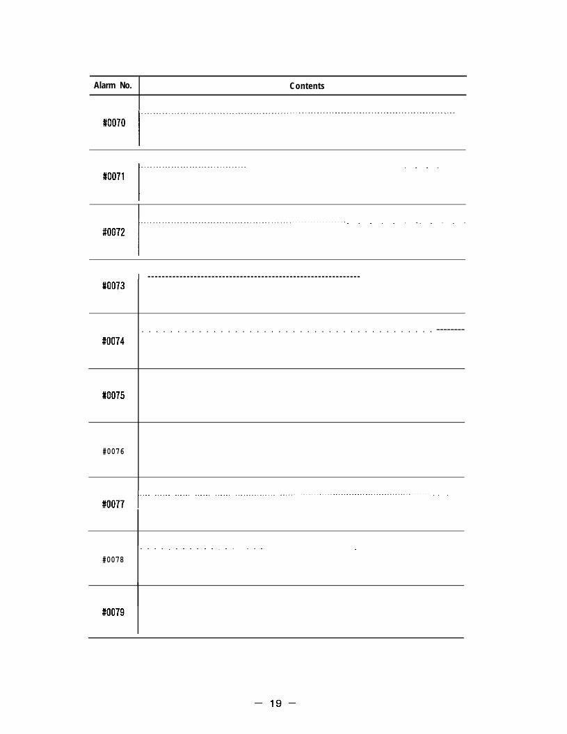
Alarm No. Contents
. . . .
. . . . . . . . . . . .
l - - - - - - - - - - - - - - - - - - - - - - - - - - - - - - - - - - - - - - - - - - - - - - - - - - - - - - - - - - - -#oo73
. . . . . . . . . . . . . . . . . . . . . . . . . . . . . . . . . . . . . . . . . --------#oo74
#oo75
#0076
l""'" ''""-" """-"" -"-""" """""" """-"-""-""-"-" """`-" """"""-""""""-""-""-"""--""""-""-"-"""----""""" . . . . . . .#oo77
. . . . . . . . . . . . . . . . . .#0078
.
–19–

7.2 ALARM NUMBER TABLE ( Cent’d)
Alarm No. Contents
l - - - - - - - - - - - - - - - - - - - - - - - - - - - - - - - - - - - - - - - - - - - - - - - - - - - - - - - - - - - - - - - - - - - - - - - - - - - - - - - - - - - - - - -#0081
. . . . . . . . . . . . . . . . . . . . . . . . . . . . . . . . . . . . . . . . . . . .
. . . . . . . .#0084
l - - - - - - - - - - - - - - - - - - - - - - - - - - - - - - - - - - - - - - - - - - - - - - - - - - - - - - - - - - - - - - - - - - - - - - - - - - -#0085
#oo86
#0087. . .
l-------------------------------------------------------------------------------------#oo88
#0089
–20–

Alarm No. Contents
#oo90
#oo91
. . . . . . . . . . . . . . . . . . . . . . . . . . . . . . . . . . . . . . . . . . . . . . . . . . . . . . . . . . .#0092
#oo93
#oo94
#oo95
. . . . . . . . . . . . . . . . . . . . . . . . . . . . . . . . . . . . . . . . . . . . . . . . . . . . . . . . . . . . . . . . . . . . . . . . . . . . . . . .#0096
#oo97
#0098
. . . . . . . . . . . . . . . . . . . . . . . . . . . . . . .#oo99
–21–

7.2 ALARM NUMBER TABLE (Cent’d)
Alarm No. I Contents
#oloo
1 BLOCK DATA OVERFLOW. . . . . . . . . . . . . . . . . . . . . . . . . . . . . . . . . . . . . . . . . . . . . . .Overflow of 1 block buffer capacity. (128 characters )
#ol 01
#ol 02
#olo3
#ol 04
ADDRESS/DATA Ml SUSE. . . . . . . . . . . . . . . . . . . . . . . . . . . . . . . . . . . . . . . . . . . . . . . . . . . . . . . . . . . . . . . . . . . . . . . . . . . . . . . . . . . . . . . . . . . . . .:~;:jre no data after the address, or command was for data without
““”—,. “ MISUSE
. . . . . . . . .Address/data not being used correctly.
UNUSABLE CHARACTER
Command is for characters that cannot be used in the significantinformation section.
NUMERIC DATA OVERFLOW. . . . . . . . .
Numeric value input data overflow. (characters being exceeded)
I UNUSABLE AXIS1--. -----. ------------------------------""--"""------"""""-'"""""""""-"-"-""""'"---""""""-""-"
#ol 05 Command is for an undefined axis.
#0106
#olo7
#0108
DOUBLE ADDRESS
Command is over two times for the same address in one block.
“ ( “, “ ) “ ERROR
lest is “ ( “.) “ is used without “ ( ~.
T h e r e i s n o ” ) - f o r “ ( .
#olo9
–22–

Alarm No. ! Contents
#ollo
—
#oIll
#ol12
MULTI PLE M CODE . .Command is for multiple Mcodes although there is no one blockmultiple command option.
M CODE DIGITS OVER
Number of M digit comands is excessive.
M91 FORMAT ERROR . . .P is not specified in the M91 block .
#ol13
#ol14
#ol 15
#0116
INTERNAL M C~AND ERROR
There is error in internal M code command.
M90/M91 CmAND ERROR
Comand M90 or M91 was used although it was unavailable.
Ml 91 FORMAT ERROR
Input command M191 contains an error.
M93 COMMAND ERROR
Command M93was used although itwas unavailable. (Option is notset.)
. . . . . . . . . . . . . . . . . . . . . . . . . . . . . . . . . . . . . . . . . . . . . . . . . . ---------- . . . . . . . . . . . . . . . --------------- ---------------
#ol17
I
#0118. . . . . . . . . . . . . . . . . . . . . . . . . . . . . . . . . . . . . . . . . . -------- ---------- ---------- ---------- . . -------- ---------- . .
. . . . . . . . . . . . ..- --------------- --------------- --------------- --------------- --------------- --------------- ““
#ol19
–23–

7.2 ALARM NUMBER TABLE (Cent’d)
Alarm No.
#o120
#o121
#o122
#01 23
#01 24
#0125
#0126
#0127
#0128
#0129
Contents
M, S, T CANNOT CHNR.
~omand was for M, S, T in a block in which M, S, T cannot bespec i f i ed.
UOC~ETION CWND
There is no K2/30 completion comand in memory operation.
MIRROR IMAGE, ERROR
Command was for G in a mirror image inwhich a mirror image cannot beused, or a mirror image is ON in a mirror image prohibited mode.
–24–

Alarm No. I Contents
MULTI PLE S CODE
#o130 Command was for multiple S codes when there were no multiple Scontrol options.
S C O D E D I G I T S O V E R
#o131 Command of the number of Sdigits was excessive.
#0132
#o133
#o134
#ol 35
#0136
I
. .
#ol 37
.#01 38
. . . . . . . . . . . . . .
#ol 39 ““””
–25–

7.2 ALARM NUMBER TABLE (Cent’d )
Alarm No. I Contents
T CODE DIGITS OVER
#o140 The T digit commands are excessive.
#o141
#0142 I
#o143
I B CODE DIGITS OVERl.-------------- . . ..----------- ..------- .--------- "-""" """-""""-"""""""""""""""""--"""--""--"--""""""-'
#0144 ]More digits than permitted were specified for Code B.
#o145
l--"" -"`"" """"" """"" """--- """------ """-----" """""-"""""""""-""-"""""-"""""""`----""""""""""""#0146
#o147
#0148
#o149
1
–26–

Alarm No. Contents
MAX OFFSET NO. OVER
#o150 Offset number is too large.
I OFFSET NO. ERROR IN H/Dl -----------------------------------------------------------------------------------------------
#o151 Off set number during H/D changeover is too I a rge,
NO. H WAND .#0152 No command for offset number H.
#o153
#ol 54
#o155. . . . . .
#01 56
. . . .
#ol 57
#0158
#ol 59
–27–

7.2 ALARM NUMBER TABLE ( Cent’d)
Alarm No.
#0160
#0161
#0162
#01 63
#0164
#0165
#o166
#01 67
#o168
#01 69
Contents
INUSABLE G CODE
:mand is for an option comanding an unusable G code.
IWTCH G CODE
:ommand is for a G code that cannot be used in combined form with~ne block.
.ACK OF ADDRESS
Iequi red address specification is lacking.
–28–

Alarm No. Contents
UNUSABLE G CODE IN CYCLE
#o170 Comand was for a G code unusable in a canned cycle.
G70–G72 USED IN NON CANNED CYCLE
#o171 G70–G72 was used in other than a canned cycle.
I
I R–POINT IN BACK BORING1------------------””” """"" """"" """"" `"""" "`-'""-"-"""""""""""-"""-"""""""-""""""-"-""""`"
#0172 Returns to R–point in G77 (back boring cycle).
#o173
G73/G83 C~AND ERROR (Q= I = O). . . . . . . . . . . . . . . . . . . . . . . . . . . . . . . . . . . . . . . . . . . . . . . . . . ---------#o174 There is no command for Qor I inG73/G83, or the command was for
G73/G83 in the 0=1=0 s t a t e .
G70–G72 ADDRESS CMAND ERROR. . . . . . . . . . . . . . . . -------------- --------------- --------------- -------
#o175 Specified address for command G70, G71, or G72 is invalid.
. . . . . . . . . . . . . . . . . . . . . . . . . . . . . . . . . . . --------- ---------- . . . . . . . . . . ---------- . . . . . . . . . . ---------- --------
#01 76
.
#o177
. . . . . . . . . . . . ..- . . . . . . . . . . . . . . . --------------- --------------- . . . . . . . . . . . . . . . --------------- ---------------
#0178
#o179. . . . . . . . . . . . . . . . . . . . . . . . . . . . . . . . . . . . . . . . . . . . . . . . . . . . . . . . . . . . . . . . . . . . . . . . . . . . . . . . . . . . . . . . . . . . . . . . . . . . . . . . . . . . .
–29–

7.2 ALARM NUMBER TABLE (Cent’d )
Alarm No.
#0180
#01 81
#0182
#0183
#01 84
#0185
#ol 86
#01 87
#ol 88
#0189
Contents
?ADIUS C~START UP ERROR
Is in ARC mode with MOO, 01, 02, 30 and with no shift within3]Iocks during start up of tool radius compensation.
?ADIUS ~END ERROR. . . . . . . . . . . . . . . . . . . . . .
1s in ARC mode at end of tool radius compensation.
JNUSABLE G C~AND IN CMP~DE
;ommand is for an unusable G code in tool radius compensation.
NRFACE UNMATCH IN ~ MODE
;orrection plane was changed over during tool radius compensation or~ominand was for an arc other than the correction plane.
RADIUS MCAL ERROR
Intersection cannot be obtained in tool radius compensation.
REVERSE CMAND IN CMF’~DE. . . . . . . . . . . . . . . . . . . . . . . . . . . . . . . . . . . . . . . . . . . . . . . . . . . . . .Comand is forretrogression of tool radius compensation or a shapeapproaching this.
ILL MACRO CWND I N CMP=
Command was for a system variable that could not be read during toolradius compensation.
CMP INTERFERENCE CHECK ALARM
Interference check was started during tool radius compensation.
CMP INTERFERENCE CHECK ERROR
Automatic interference correction is not being conducted durradius compensation.
ng tool
W ABNORMAL ERROR . . . . .=sation mode abnormal or no output data during data output (logic
* This” alarm normally does not occur.
–30–

Alarm No. Contents
RADIUS O IN CIRCULAR
#o190 Command is for a radius O circle in the arc command.
TOO MANY AXES IN CIRCULAR
#o191 The command is for more than three axes in the arc.The command is for axes exceeding those helically possible.
1
CANNOT DECIDE CIRCULAR SURFACE
#0192 Cannot decide plane from the assigned arc command.Command is for anarc with more than 4axes.
I RADIUS R C~AND ERRORl.----- . . ..-. ---- . . ..----------- .----- .-------- ..-------------------.-----"""""""""'""""""
#o193 Unable to obtain the center from the R command.
OFFSET IN CIRCULAR ~DE
#o194 Command is for tool length offset and tool position offset in thecircular mode.
#o195
#0196
#o197
I
. . . . . . . . . . . . . . . --------------- --------------- --------------- . . . . . . . . . . . . . . . . . . . . . . . . . . . . . . ---------------#0198
#o199
–31–

7.2 ALARM NUMBER TABLE (Cent’d )
Alarm No.
#0200
#0201
#0202
#0203
#0204
#0205
#0206
#0207
#0208
#0209
Contents
P NO. MAX OVER ING1O. . . . . . . . . . . . . . . . . . . . . . . . . . . . . . . . . . . . . . . . . . . . . . . . . . . . . . . . . . . . . . . . . . . . . . . . .Number specifying P is too large in the offset program input.
G1O FORMAT ERROR
The amount of offset is too great at the offset program input or thereis an error in one of the program formats.
PNO. MAX OVER ING1O 02
P is too large in G1O (I2 (work coordinate shift program input).
. . . . . . . . . . . . . . . . . . . . . . . . . . . . . . . . . . . . . . . . . . . . . . . . . . . . . . . . . . . . . . . . . . . . .
. . . . . . . . . . . . . . . . . . . . . . . . . . . . . . . . . . . . . . . . . . . . . . . . . . . . . . . . . . . . . .
. . . . . . . . . . . . . . . . . . . . . . . . . . . . . . . . . . . . . . . . . .
I
. . . . . . . . . . . . . . . . . . . . . . . . . . . . . . . . . . . . . . . . . . . . . . . . . . . . . . .
–32–

Alarm No, I Contents
CONSTANT DATA OUT OF RANGE
#021 o Constant exceeds limit range in microprogram.
UNMATCH G67 COhTvlAND
#021 1 Too many G67 cancel codes.
MACRO FORMAT ERROR
#021 2 Error in format.
UNDEF I NED # NO.
#0213 Value not defined as variable No. being used.
ILL LEFT SIDE # NO.. . . . . . . . . . . . . . . . . . . . . . . . . . . . . . .
#0214 Variable of the assignment statement is a variable in which assignmentis prohibited.
[ ] LIMIT OVER
#0215 Multiplicjtyof brackets exceeds the upper limit.
—MACRO CALL LIMIT OVER
#0216 Multipl icityof macro call exceeds the upper limit,
DO-END FORMAT ERROR
#0217 DO-END do not correspond 1 to 1.
[ 1 UNMATCH
#021 8 The number of brackets do not correspond correctly.
DO-END NO. OUT OF RANGE
#021 9 DO not within the range of lSm=3withm.
–33–

7.2 ALARM NUMBER TABLE (Cent’d )
Alarm No.
#0220
#0221
#0222
#0223
#0224
#0225
#0226
#0227
#0228
#0229
Contents
~TO NO. FORMAT ERROR. . . . . . . . . . . . . . . . . . .rhe n of GOTO n exceeds the comand range or n cannot be found.
)DIVIDE IN MACRO
)ivided with O in macro.
?OOT VALUE NEGATIVE
Iegative number is in the root sign.
‘LOATING DATA OUT OF RANGE
‘Ioating decimal point data exceed the permissible range.
:66–M99 PROG ERROR
bismove comand sent by modal call (G66) during M99 return.
MACRO SYSTEM ERROR
Overflow of operation stock.
ASIN, ACOS, LN, SORT ERROR
Exceeded area with ASIN, ACOS, LN or SORT functions.
TRANSFORMATION DATA OVERFLOW
Overflow occurred during integral conversion.
BCD INPUT DATA OVERFLOW
Input data overflowing in BCD function.
BIN FORMAT ERROR
Error in formatting with the BIN function.
–34–

Alarm No. Contents
EXP OUTPUT DATA OVERFLOW
#0230 Overflow occurred with EXP function.
1
1“--”””””””””””””””””””””””””””””””””’”-””””. . . .. . . . . . . . . . . . . . . . . . . . . . .
#0231
—
#0235
#0236
l------------------ . . . ..----- . ..------ . ..---- .-. ----- . ..---------""""""-""----""""-----"""""-"----"""-'#0237
.#0238
.
#0239
–35–

7.2 ALARM NUMBER TABLE (Cent’d)
Alarm No. ] Contents
#0240
ZR UNREADY
Reference point return of axes with G29 and G30 commands not complete.
#0241
#0242
#0243
#0244
#0245
ZR DISABLE
Reference point return of axis with G28 command is invalid.
. . . . . . . . . . . . . . . .
#0246
. . . . . . . . . . . . . . . . . . . . . . . . . . . . . . . . . . . . . . . . . . . . . .#0247
I. . . . . . . . . . . . . . . . . . . . . . . . . . . . . . . . . . .
#0248
#0249
–36–

Alarm No. Contents
UNUSABLE CODE IN SOLID TAP
#0250 Comand issued for code not usable with solid tap..
#0253l`-""-"""""-""""'"-'"'"--"""""""""""""""""""""--"-"--""""""-----""''"""""-""""""""""""-'--"-"-""""""""I
. . . . . . . . . . . . . . . . . . . .#0254
C– AX I S CWAND FOR SPl NDLE
#0255 C–axis command was used for spindle in spindle control mode.
SPINDLE CHNDFOR C – A X I S
#0256 Scomand was used for spindle in C–axis control mode.
. . . . . . . . . . . . . . . . . . . . . . . . . . . . . . . . . . . . . . . . . . . . . . . . . .#0257
#0258
#0259
–37–

7.2 ALARM NUMBER TABLE (Cent’d)
Alarm No.
#0260
#0261
#0262
#0263
#0264
#0265
#0266
#0267
#0268
#0269
Contents
SUBPRO, MACRO CALLING ERROR. . . . . . . . . . . . . . . . . . . . . . . . . . . . . . . . . . . . . . . . .There is noPor Cl speci f icat ion in the M98 b lock . There isno Pspecification in the G65/G66 and G25 blocks. Simultaneous command ofG25 and M98/M99.
SUBPRO C A L L L I M I T O V E R
Multipl icityof M98SUBPR0 and G25 calling exceeded the limit.
NO CALLED PROGRAM
Program No. or sequence No. not found when caM99, G65, G66, G25, G, Mor T.
SEARCH AFTER READ SUB/MACRO
Iing program with M98,
. . . . . . . . . . . . .Tried to start after reading SUBPRO and MACRO CALL and executingADDRESS SEARCH. .
PROGRAM COPY M99 USED
M99 was used in program to be copied.
. . . . . . . . . . . . . . . . . . . . . . . . . . . . . . . . . . . . . . . . . . . . . . . . . . . . . . . . . . . . . . . . . . . . . . . . . . . . . . . . .
. . . . . . . . . . . . . . . . . . . . . . . . . . . . . . . . . . . . . . . . . . . . . . . . . . . . . . . . . . . . . . . . . . . . . . . . . .
–38–

Alarm No. Contents
#0270
CORNER OVERRIDE G CODE ERROR
No,l or J command. No command for both I and J. Command is for anaxis other than the X—and Y—axes.
#0272
. . . . . . . . .
#0273
#0274
#0275
. . . . . .
UNUSABLE G CUND DURING PROGRAM INTERRUPT. . . . . . . . . . . . . . . . . . . . . . . . . . . . . . . . . . ------- ---------- ---------- ---------- ---------- ---------- --------Input cmand is unusable during program interrupt.
#0276
#0277
#0278
#0279
. .
–39–

7.2 ALARM NUMBER TABLE (Cent’d)
Alarm No.
#0280
#0281
#0282
#0283
#0284
#0285
#0286
#0287
#0288
#0289
Contents
UNUSABLE G CODE IN SCALING
Command is for an unusable G code in the scaling mode.
SCALING FORMAT ERROR
Error inG500r G51 block format, or scaling factor is O.
. . . . . . . . . . . . . . . . . . . . . . . . . . . . . . . . . . . . . . . . . . . . . . . . . . . . . . . . . . . .
. . . . . . . . . . . . . . . . . . . . . . . .
COMBINATION FUNCTION ERROR. . . . . . . . . . . . . . . . . . . . . . . . . . . . . . . . . . . . . . . . . . . . . . . . . . . . . . . . . . .Mirror image, scaling, and/or coordinate rotation functions areset or canceled in inappropriate order.
. . . . . . . . . . . . . . . . . . . . . . . . . . . . . . . . . . . . . . . . . . . .
. . . . . . . . . . . . . . . . . . . . . . . . . . . . . . . . . . . . . . . . . . . . . . . . . . . . . . . . . . .
–40–

Alarm No.
#0290
—
#029
#0292
#0293
#0294
#0295
#0296
#0297
#0298
#0299
Contents
%0 No. NOT FOUND AT PRN
sequence No. not found when restarting program.
COORDINATE SHIFT AT PRN
lperat ion changing the coordinate system was conducted when restartingthe program (G50/G92, G54–G59 executed with MDl command, ORG>perat ion)
ml ~VED AT PRN
4xis moved with intervention of MDl when restarting program.
. .
–41–

7.2 ALARM NUMBER TABLE (Cent’d )
Alarm No. Contents
LIFE CTRL NOT GROUPING. . . . . . . . . . . . . . . . . . . . . . . . . . . . . . . . . . . . . . . . . . . . . . . . . . . . . . . . . . . . . . . . . . . . . . . . .
#0301 No tool in specified tool group is registered.
ILIFE CTRL (ALL SKIP)
. . . . . . . . . . . . . . . . . . . . . . . . . . . . . . . . . . . . . . . .#0302 All tools unspecified tool group were skipped.
#0303
I
#0304
#0305
. . . . . . . . . . . . . . . . . . . . . . . . . . . . . . . . . . . . . . . . . . . . . . . . . . . . . . . . . . . . . . . . .#0306
. . . . . . . . . . . . . . . . . . . . . . . . . . . . . . . . . . . . . . . . . . . . . . . . . . . . . . . . . . . . . . . . . . . . . . . . . .#0307
I
#0309
–42–

Alarm No. Contents
#0310
ROTATION G COOE MISUSE
Command was for unusable G code in coordinate rotation mode, or wasfor G68 during radius offset.
ROTATION FORMAT ERROR
#031 1 Error inG680r G69 command block format.
#031 2
. . . . . . . . . . . . . . . . . . . . . . . . . . . . . . . . . . . . . . . . . . . . . . . . . . . . . . . . . . . . . . . . . . . . . . .#0313
I
#0314
I. . . . . . . . . . . . . . . . . . . . . . . . . . . . . . . . . . . . . . . . . . . . . . . . . . . . . . . . . . . . . . . . . . . . . . . . . . . . . . . . . . . . . . . . .
#0315
#0316
#0317
. . . . . . . . . . . . . . . . . . . . . . . . . . . . . . . . . . . . . . . . . . . . . . . . . . . . . . . . . . .
. . . . . . . . . . . . . . . . . . . . . . . . . . . . . . . . . . . . . . . . . . . . . . . . . . . . . . . . . . . . . . . . . . . . . . . . . . . . . . . . . . . . . . . . .
#031 8
l---------------------------------------------------------------------------------------------------------#0319
–43–

7.2 ALARM NUMBER TABLE (Cent’d )
Alarm No.
#0320
#0321
#0322
#0323
#0324
#0325
#0326
#0327
#0328
#0329
Contents
NORK COORDINATE FORMAT ERROR. . . . . . . . . . . . . . . . . . . . . . . . . . . . . . . . . . . . . . . . . . . .Work coordinate not usable in G54–G59 $ work coordinate shift wasselected, or command is for G54—G59 in the circle mode.
.OCAL COORDINATE FORMAT ERROR
.ocal coordinate system set when work coordinate not in set state.
;53 ERROR
353 set under unusable G53 condition.
. . . . . . . . . . . .
. . . . . . . . . . . . . . . . .
–44–

Alarm No. Contents
#0330
#0331
#0332
#0333
. . . . . . . . . . . . . . . . . . . . . . . . . . . . . . . . . . . . . . . . .
#0334
#0335
. . . . . . . . . . . . . . . . . . . . . . . . . . . . . . . . . . . . . . . . . . . . . . . . . .#0336
–45–

7.2 ALARM NUMBER TABLE (Cent’d )
Alarm No. Contents
D> RCWND lNG12/G13
#0360 Command was for radius R < correction D when cutting circle.
PLANE lNG12/G13
#0361 Command is for other than G17 plane when cutting circle.
I FORMAT ERROR. . . . . . . . . . . . . . . . . . . . . . . . . . . . . . . . . . . . . . . . . . . . . . . . . . . . . . . . . . . . . . . . . . . . . . . . . .#0362 True circle cutting format error.
UNUSABLE GCODE IN G45–G48
#0365 Cmand was for unusable G when correcting with G45–G48.
#0366
#0367
. . . . . . . . . . . . . . . . . . . . . . . . . . . . . . . ------ ------ . . . . . . ------ ------ ------ ------ . . . . . . ------ . . . . . . . . . .
#0368
#0369
–46–

Alarm No. Contents
F C~AND= O
#0370 F is lacking in the cutting comand.
#0371
. . . . . . . . . . . . . . . . . . . . . . . . . . . . . . . . . . . . . . . . . . . . . . . . . . . . . . . . . . . . . . . . . . . . . . . . . .#0372
I. . . . . . . . . . . . . . . . . . . . . . . . . . . . . . . . . . . . . . . . . . . . . . . . . . .
#0374
I. . . . . . . . . . . . . . . . . . . . . . . . . . . . . . . . . . . . . . . . . . . . . . . . . . . . . . . . . . . . . . . . . . . . . . . . . . . . . .
#0375
#0376
#0377
#0378
. . . . . . . . . . . . . . . . . . . . . . . . . . . . . . . . . . . . . . . . . . . . . . . . . . . . . . . . . . ------ . ----- ------ ------ . . . . . .#0379
–47–

7.2 ALARM NUMBER TABLE (Cent’d )
Alarm No.
#0380
#0381
#0382
#0383
#0384
#0385
#0386
#0387
#0388
#0389
Contents
AXiSCANNOTC~AND (1)
An axis command is in the G04, G20, G21 block.
AXIS CANNOT C-D (2). . . . . . . . . . . . . . . . . . . . . . . . . . . . . . . . . . . . . . . . .An axis command is in the G1O, G22, G23 block.
S–OT CO MM A N D E R R O R
Several areas among 3rd to5th areas were selected.
. . . . . . . . . . . . . . . . . . . . . . . . . . . .
. . . . . . . . . . . . . . . . . . . . . . . . .
. . . . . .
–48–

Alarm No. Contents
#0390
PROGRAM O NUMBER NOT FOUND. . .
Program to be executed was not found.
PROGRAM BEING READ
#0391 Program to be executed was being loaded.
#0392
#0393
PROGRAM BEING EDITED
Program to be executed was being edited.
SEQUENCE NUMBER NOT FOUND. . . .
Specified sequence number was neither M98Q command or G25.
#0394
#0395
IMPOSSIBLE REQUEST DURING MEM/TAPE OPERAT 10N
Change to memory/tape mode and cycle start was requested intape/memory mode.
#0396
CANNOT RETURNIN TAPE/DIRECT
An attempt to return to the main program was made by programinterruption during TAPE/DIRECT operation.
] INTERRUPT ACTION (TAPE/DIRECT)l----------------------- .---------------- .------------ .-------- """"" ""--" """"" --""" """"" """"" ""-"--"
#0397 I Interference was made so that re–execution would be impossible.
#0398
. . . .#0399
. . . . . . . . . . . . . .
–49–

7.2 ALARM NUMBER TABLE (Cent’d)
Alarm No.
#0400
#0401
#0402
#0403
#0404
#0405
#0406
#0407
#0408
#0409
Contents
)N~R FIGURE OVER
)number with 5-digit or more is commanded.
tNMER FIGURE OVER
I number with 5-digit or more is comanded.
> NMER FIGURE OVER. . . . . . . . . . . . . . . . . . . . . . . . . .
> number with 5-digit or more is comanded.
. . . . . . . . . . . . . . . . . . . . . . . . . . . . . . . . .
. . . . . . . . . . . . . . . . . . . . . . . . . . . . . . . . . . . . . . . . . . . . . . . . . . . . .
–50–

Alarm No. Contents
#041 o
ZR UNREADY (X)
#041 1 Reference point return incomplete. (X–axis)
ZR UNREADY (Y)
#0412 Reference point return incomplete. (y–axis)
1----------------------------------------ZR UNREADY (Z)
#0413 Reference point return incomplete. (z-axis)
ZR UNREADY (4)
#0414 Reference point return incomplete. (4th–axis)
ZR UNREADY (5)
#041 5 Reference point return incomplete. (5th–axis)
#0416 I
#041 7
–51–

7.2 ALARM NUMBER TABLE (Cent’d )
Alarm No.
#0420
#0421
#0422
#0423
#0424
#0425
#0426
#0427
#0428
#0429
Contents
DEFERENCE POINT RETURN ERROR (X)
(–axis has not returned to reference point after comand G27.
EFERENCE POINT RETURN ERROR (Y)
f–axis has not returned to reference point after command G27.
?EFERENCE POINT RETURN ERROR (Z)
~–axis has not returned to reference point after comand Ci27.
?EFERENCE POINT RETURN ERROR (4)
!th axis has not returned to reference point after command G27.
?EFERENCE POINT RETURN ERROR (5). . . . . . . . . . . . .
jth axis has not returned to reference point after command G27.
. . . . . . . .
–52–

Alarm No. Contents
l.--- .----------- .-.. -... ----... -- . . ..------- ..-----.-.-.--.....---------""-"`"""""-"--#0430
#0432
#0433I
#0434
#0437
l--------------------- ..---------------- ..----- ...-------------"-""-"""--"--""""""--""""""""-#0438
#0439. .
–53–

7.2 ALARM NUMBER TABLE (Cent’d)
Alarm No.
#0490
#0491
#0492
#0493
#0494
#0495
#0496
#0497
#0498
#0499
Contents
NO SKIP SIGNAL (1) RECEIVED
Skip signal (1) not receivable inG31 b lock .
. . . . . . . . . . . . . . .
SKIP SIGNAL (1) DISABLE
Disable of skip signal (1) when executing G31.
. . . . . . . . . . . . . . . . . . . . . . . . . . . . . . . . . . . .
. . . . . . . . . . . . . . . . . . . . .
. . . . . . .
–54–

Alarm No. I Contents
DNC TlfiiE OUT
#1 000 DNC t imeout error .
DNC DR–L I NE ERROR
#lool DNCDR line error.
DNC PACKET LENGTH ERROR. . . . . . . . . . . . . . . . . . . . . . . . . . . . . . . . . . . . . . . . . . . . . . . . . . . . . . . . . . . . . . . . . . .
#loo2 DNC packet length abnormal.
DNCLSI ERROR. . . . . . . . . . . . . . . . . . . . . . . . . . . . . . . . . . . . . . . . . . . . . . . . . . . . .
#1 003 DNC 8251 error.
DNC CHECK S~ ERROR
#1 004 DNC Check sum error.
DNC CHND ERROR
#1 005 DNC Comand error.
DNCHISPEED~DE ERROR
#1 006 DNChigh speed cutting mode error.
DNC Cm I CATION MODULE DIAGNOSIS ERROR
#1 007 DNC communication module diagnosis error.
DNC CPU ERROR
#1 008 DNC CPU error.
DNC 51 ERROR
#1 009 DNC51 error.
–55–

7.2 ALARM NUMBER TABLE (Cent’d )
Alarm No.
#lolo
#loll
#lo12
#lo13
#lo14
#lo15
#1016
#lo17
#1018
#lo19
Contents
. .
–56–

Alarm No. Contents
SEQUENCE ERROR O
#1 080 Sequence error O. Block stops.
#1081
#1082
. . . . . . . . . . . . . . . . . . . . . . . . . . . . . . . . . . . . . . . .#1 083
. . . . . . . . . . . . . . . . . . . . . . . . . . . . . . . . . . . . . . . . . . . . . . . . . . . . . . . . . . . . . . . . . . .#1 084
#l 085
. . . . . . . . . .#lo86
#1 087
#1 088
#l 089
–57–

7.2 ALARM NUMBER TABLE ( Cent’d)
Alarm No. I Contents
MEMORY ERROR (SET)
#1 090 Setting area total check error.
MEMORY ERROR (PRM)
#lo91 Parameter area total check error.
MEMORY ERROR (KEEP MEM)
#1 092 Keep memory area total check error.
MEMORY ERROR (OFS). . . . . . . . . . . . . . . . . . . .
#1 093 Offset and work coordinate shift area total check error.
MEMORY ERROR (MACRO)
#1 094 Macro variable area total check error.
~MORY ERROR (PROGRAM)
#1 095 Processing progr”am area total check error.
MEMORY ERROR (TOOL LIFE)
#1 096 Tool life management area total check error.
#1 097
#1 098
OVER TEMP
#1 099 Temperature in panel abnomal.
–58–

Alarm No. I Contents
#2000
#2001
#2002
OT (X)
Over – travel. (X – axis)
.oT..(y.) . . . . . . . . . . . . . . . . . . . . . . . . . . . . . . . . . . . . . . . . . . . . . . . . . . . . . . . . . . . . . . . . . . . . . . . . . . . . . . . . . . . . . . . . . . . . . . . . . .Over–travel. (Y – axis)
#2003.oT..(z) . . . . . . . . . . . . . . . . . . . . . . . . . . . . . . . . . . . . . . . . . . . . . . . . . . . . . . . . . . . . . . . . . . . . . . . . . . . . . . . . . . . . . . . . . . . . . . . . . .Over –travel. (Z – axis)
#2004
OT (4)
Over– travel. (4th – axis)
#2005
OT (5)
Over–travel. (5th–axis)
#2006 l---`""--"--"""""""""""-`--"""-"'""""""--""""""-"""""'""""`""`"""-"""""""""""-"""""'""""""-"""""--"-"-`""""
#2007. . . . . . . . . . . . . . . . . . . . . . . . . . . . . . . . . . . .
#2008l"'"""""""-""--""-""""-`"""`"""""""""""""""""""-"""""""""""`""""""""""""""""""""""""""""-"-"-""""""""""`"""'I
#2009
–59–

7.2 ALARM NUMBER TABLE (Cent’d)
Alarm No. I Contents
#2010
S–OT1 (X). . . . . . . . . . . . . . . . . . . . . . . . . . . . . . .
#201 1 Stored stroke limit. First area. (X–axis)
S–OT1 ( Y ). . . . . . . . . . . . . . . . . . . .
#2012 Stored stroke limit, First area. (Y–axis)
S–OT1 ( Z )
#2013 Stored st roke l imi t . F i rs t area . (Z–axis)
S–OT1 ( 4 )
#2014 Stored st roke l imi t . F i rs t area . (4 th–axis)
S–OT1 (5). . .
#201 5 Stored stroke limit. First area. (5th–axis)
I
#2016
. . . . .#201 7
#2018
#2019
–60–

Alarm No. I Contents
#2020
S–0T2 (X). . . . . . . . . . . . . . . . . . . . . . . . . . . . . . . . . . . . . . . . . . . . . . . . . . . . . . . . . . . . . .
#2021 Stored stroke limit. Outside second area. (X–axis)
S–0T2 (Y)
#2022 Stored stroke limit. Outside second area. (Y–axis)
IS–0T2 (Z). . . . . .. . . . . . . . . . . . . . . . . . . . . . . . . . . . . . . . . . .
#2023 Stored stroke limit. Outside second area. (z–axis)
S–0T3 ( X )
#2024 Stored stroke limit. Outside third area. (X–axis)
S–0T3 (Y) ‘
#2025 Stored stroke limit. Outside third area. (Y–axis)
S–0T3 (Z). . . . . . . . . . . . . . . . . . . . . . . . . . . . . . . . . . . . . . . . . . . . . . . . . . . . . . . . . . . . . . . . . . . . . . . . . . . . . . . . . .
#2026 Stored stroke limit. Outside third area. (Z–axis)
S–0T4 ( X )
#2027 Stored stroke limit. Outside fourth area. (X–axis)
S–0T4 ( Y )
#2028 Stored stroke limit. Outside fourth area. (Y–axis)
S–0T4 (Z)
#2029 Stored stroke limit. Outside fourth area. (Z–axis)
–61–

7.2 ALARM NUMBER TABLE (Cent’d )
Alarm No.
#2030
#2031
#2032
#2033
#2034
#2035
#2036
#2037
#2038
#2039
Contents
. . . . . . . . . . . . . . . . . . . . .
3–0T5 (X). . . . . . . . . . . . . . . . . . . . . . . . . . . .$tored stroke limit. Outside fifth area. (X–axis)
;–0T5 (Y). . . . . . . . . . . . . . . . . . . . . . . . . . . . . . . . . . . . . . . . . .Stored stroke limit. Outside fifth area. (Y–axis)
;–0T5 ( Z ). . . . . . . .
stored stroke limit. Outside fifth area. (Z–axis)
. . . . . . . . .
. . . . . . . . . . . . . . . . . . . . . . . . . . . . . . .
. . . . . . . . . . . . . . . . . . . . . . . . . . . . . . . . . . . . . . . . ---------- . . . ---------- ---------- ----
–62–

Alarm No. I Contents
#2040
S–0T2 (INSIDE)
Stored stroke limit. Inside second area.
#2041
#2042
S–0T3 (INSIOE)
Stored stroke limit. Inside third area.
S–0T4 ( INSIDE)
Stored stroke limit. Inside fourth area.
S–0T5 ( INSIDE). . . . . . . . . . . . . . . . . . . . . . . . . . . . . . . . . . . . . . . . .
#2043 Stored st roke l imi t . Ins ide f i f th area .
#2044
#2045
. . . . . . .
#2046
#2047
l"""""-"""--""""""`""""""--"""-""-""""""""""----"""""-""""---""""""-"""--"-""""""-`--"--""-""----"". . . . . .
#2048
I
#2049
–63–

7.2 ALARM NUMBER TABLE (Cent’d)
Alarm No.
#2050
#2051
#2052
#2053
#2054
#2055
—
#2056
#2057
#2058
#2059
Contents
. . . . . . . . .
\. . . . . . . . . . . . . . .
–64–

Alarm No. I Contents
ZR ERROR UNDER MANUAL SKIP MODE
#2060 Reference point return (low–speed type) was executed during manualskip B (measuring).
ZR AREA ERROR (X). . . . . . . . . . . . . . . . . . . . . . . . .
#2061 Reference point return area error. (X–axis)
ZR AREA ERROR (Y)
#2062 Reference point return area error. (Y–axis)
ZR AREA ERROR (Z)
#2063 Reference point return area error. (Z–axis)
ZR AREA ERROR (4). . . . . . . . . . . . . . . . . . . . . . . . . . . . . .
#2064 Reference point return area error. (4th–axis)
IZR AREA ERROR (5)
. . . . . . . . . . . . . . . . . . . . . . . . . . . . . . . . . . . . . . . .#2065 Reference point return area error. (5th–axis)
.
#2067
–65–

7.2 ALARM NUMBER TABLE (Cent’d )
Alarm No.
#2070
Contents
TOUCH AX NOT RET
Measurement was made without retracting the contact axis after comple-tion of measurement by manual skip (A/B).
ZR POSITION ERROR (X). .
#2071 Reference point return position error. (X–axis)
] ZR POSITION ERROR (Y)l ----------------------------------------------------------------------------------------------------
#2072 Reference point return posit ion error. (Y–axis)
#2073
ZR POSITION ERROR (Z)
Reference point return position error. (Z–axis)
#2074
ZR POSITION ERROR (4)
Reference point return position error. (4th–axis)
ZR POSITION ERROR (5)
#2075 Reference point return position error. (5th–axis)
#2076
#2077
#2078
#2079
–66–

Alarm No. Contents
#2080
ZR DECLS ERROR (X)
#2081 Deceleration LS goes OFF-ON again after going ON once at thereference return point. (X–axis)
Z R ECLS ERROR (Y)
#2082 Decelerat ion LSgoes OFF-oNaga in after going ON once at thereference return point. (Y–axis)
I ZR DECLS ERROR (Z)l.-. -.----- .-. --------- .-. ------ .------ .-------------- ..------.-------------.-----"""""""---"""""""
#2083 Decelerat ion LSgoes OFF-oNaga in after going ON once at thereference return point. (Z—axis)
ZR DECLS ERROR (4). . . . . .
#2084 Decelerat ion LSgoes OFF-oN again after going ON once at thereference return point. (4th–axis)
IZRDECLS ERROR ( 5 )l---... ------ ..--------------------------------"""""""""---"""""""--""""""""-""---"""""""--""-"
#2085 Decelerat ion LSgoes OFF-oNaga in after going ON once at thereference return point. (5th–axis)
#2086
#2087
#2088
. . . . . . . ..- . ---------- ---------- ---------- ---------- ---------- . --------- ---------- ------- . . .
#2089
–67–

Alarm No. I Contents
7.2 ALARM NUMBER TABLE ( Cent’d )
#2090
ZR PRM ERROR (X)
#2091 Parameter setting is such that Pull back operation is compulsory atthe reference return point. (X–axis)
ZR PRM ERROR (Y)
#2092 Parameter setting is such that Pull back operation is compulsory atthe reference return point. (Y–axis)
ZR PRM ERROR (Z)
#2093 Parameter setting is such that Pull back operation is compulsory atthe reference return point. (Z–axis)
ZR PRM ERROR (4)
#2094 Parameter setting is such that pull back operation is compulsory atthe reference return point. (4th–axis)
ZR PRM ERROR (5)
#2095 Parameter setting is such that Pull back operation is compulsory atthe reference return point. (5th–axis)
#2096
#2097
#2098
. . . . . . . . . . . . . . . . . . . . . . . . . . . . . . . . . . . . . ---------- ---------- ---------- ---------- ---------- ---------- ---
#2099
–68–

Alarm No. I Contents
#21 00
P–SET ERROR (X). . . . . . . . .
#2101 P–SET error. (X–axis)
P–SET ERROR (Y)
#21 02 P–SET error. (Y–axis)
P–SET ERROR (Z)
#21 03 P–SET error. (Z–axis)
P–SET ERROR (4)
#21 04 P–SET error. (4th–axis)
P–SET ERROR (5)
#2105 P–SET error. (5th–axis)
l"""-""" """""" ""--"" --"""" "-"""" '"-""" `-""-" """---""" """""" """-`" """""" "-""-" --"""" "-"-"" ""-"" . . . .#21 06
L#2109
–69–

7.2 ALARM NUMBER TABLE (Cent’d)
Alarm No.
#21 10
#21 11
#21 12
#21 13
#2114
#2115
#2116
#2117
#2118
#21 19
Contents
.
. . . . . . . . . . . . . . . . . . .
–70–

Alarm No. I Contents
#2131
#2132
#21 33
ABSO POS CHECK ERROR (X)
The difference between the positions when the power supply of theabsolute position detecting function is turned on and when the powersupply is turnd off at the previous time is large.
ABSO POS CHECK ERROR (Y)
The difference between the positions when the power supply of theabsolute position detecting function is turned on and when the powersupply is turned off at the previous time is large.
ABSO POS CHECK ERROR (Z). . . . . . . . . . . . . .
The difference between the positions when the power supply of theabsolute position detecting function is turned on and when the powersupply is turned off at the previous time is large.
#2134
‘ ABSO POS CHECK ERROR (4)
The difference between the positions when the power supply of theabsolute position detecting function is turned on and when the powersupply is turned off at the previous time is large.
#21 35
I ABSO POS CHECK ERROR (5)1--------------------------------------------------------------------"---------------------"------------"-----------"-------"-
The difference between the positions when the power supply of theabsolute position detecting function is turned on and when the powersupply is turned off at the previous time is large.
#21 36
#2137
#2139
–71–

7.2 ALARM NUMBER TABLE (Cent’d )
Alarm No.
#2160
#2161
#2162
#2163
#21 64
#21 65
#2166
#2167
#21 68
#2169
Contents
.
DETACHED AXIS SERVO ON (X)
Detachment input went on when servo was on. (X–axis)
DETACHED AXIS SERVO ON (Y)
Detachment input went on when servo was on. (Y–axis)
DETACHED AXIS SERVO ON (Z)
Detachment input went on when servo was on. (Z–axis)
DETACHED AXIS SERVO ON (4). . . . . . .Detachment input went on when servo was on. (4th–axis)
DETACHED AX 1 S SERVO ON (5)
Detachment input went on when servo was on. (5th–axis)
–72–

Alarm No. I Contents
#21 70
AXIS DETACHED STATUS UNMATCH (X)
#2171 Detachment input went off when X– axis was disconnected. (X-axis)
AXIS DETACHED STATUS UNMATCH (Y)
#21 72 Detachment input went off when Y–axis was disconnected. (Y-axis)
I AXIS DETACHED STATUS UNMATCH (Z)l------------------------"--"---"--""-"""-""-""""""""""""""'
#21 73 Detachment input went off when Z– axis was disconnected. (Z-axis)
I AXIS DETACHED STATUS UNMATCH (4)l - - - - - - - - - - - - - - - - - - - - - - - - - - - - - - - - - - - - - - - - - - - - - - - - - - - - - - - - - - - - - - - - - - - - - - - - - - - - - - - - - - - - - - - -
#2174 Detachment input went off when 4th axis was disconnected. (4th-axis)
AXIS DETACHED STATUS UNMATCH (5)
#2175 Detachment input went off when 5th axis was disconnected. (5th-axis)
#2176
#2177
—- 1
#21 78
#21 79
–73–

7.2 ALARM NUMBER TABLE [Cent’d )
Alarm No.
#2180
#2181
#2182
#2183
#21 84
#21 85
#2186
#2187
#2188
#2189
Contents
SEQUENCE ERROR 1. . . .
Sequence error 1. Coasting stop.
. . . . . . . . . . . . .
C–AXIS SWITCHING ERROR (Cl)
Request for switching changed during change to C–axis control mode.
C–AXISSERVO OFF SWITCHING ERROR (Cl)
C–axis servo off request was issued while C–axis was changedafter valid indexing of C—axis.
C–AXISSWITCHING PROGRAM EXECUTION ERROR (Cl) . .C–axis switching request was issued while program was executed.
–74–

Alarm No. I Contents
MACH I NE UNREADY. . . . . . . . . . . . . . . . . . . . . . . . . . . . . . . . . . . . . .
#2190 Machine not ready.
I SOLID TAP SPINDLE LOOP-ON ERROR (1)l - - - - - - - - - - - - - - - - - - - - - - - - - - - - - - - - - - - - - - - - - - - - - - - - - - - - - - - - - - - - - - - - - - - - - - - - - - - - - - - - - - - - - - - - - - - - - - - - -
#2191 SLPC input went off during spindle position loop–on sequence ofG93.
#2192
. . . . . . . . . . . . . . . . . . . . . . . . . . . . . . . . . . . . . . .
l---------------------------------------------------------------------------------------------------#21 94
. . . . . . . . . . . . . . . . . . . . . . . . . . . . . . . . . . . . . . . . . . . . . . . . . . . . . . . . . . . . . . . . .
#21 96
–75–

7.2 ALARM NUMBER TABLE (Cent’d)
Alarm No.
#3000
#3001
#3002
#3003
#3004
#3005
#3006
#3007
#3008
#3009
Contents
SERVO OFF
Servo power not ready.
NC UNREADY
NC not ready.
EMERGENCY STOP. . . . . . . . . . . . . . . . .Emergency stop not ready.
. . . . . . . . . . . . . . . . . . . . . . . . .
. . . . . . . . . . . . . . . . . . . . . . . . . . . . .
. . . . . . . . . . . . . . . . . . . . . . . . . .
–76–

Alarm No. I Contents
#3010
UNFINISHED PROG GEN
Processing program memory not initialized.
#3011
UNSUITABLE PROG KMORY
Processing program expansion memory and memory when power is turnedon do not match when initializing.
#3012
#301 3
UNSUITABLE AXIS PRM.
Axis configuration parameter and physical shaft configuration do notmatch.
#301 4
. . . . . . . . . . . . . . . . . . . . . . . . . . . . . . . . . . . . . . . . . . . . . . . . . . . . . . . . . . .#3016
l - - - - - - - - - - - - - - - - - - - - - - - - - - - - - - - - - - - - - - - - - - - - - - - - - - - - - - - - - - - - - - - - - - - - - - - - - - - - - - - - - - - - -#301 7
#3018
#3019
–77–

7.2 ALARM NUMBER TABLE (Cent’d)
Alarm No.
#3020
#3021
#3022
#3023
#3024
#3025
#3026
#3027
#3028
#3029
Contents
–78–

Alarm No. I Contents
#3030
l . . . . . . . . . . . . . . . . . . . . . . . . . . . . . . . . . . . . . . . . . . . . . . . . . . . . . . . . . . . . . . . . . . . . . . . . . . . . . . . . . . . . . . . . . . . . . . . . . . . . . . . . .#3031
#3032 l-----"-"----""""-"--`-""""""""-"'""""--"-""""-""-"--""-"-"""""""""""""""""-"""""""-"--"""""""""""""""-""
#3033l-""----"""--"-"""------"""""""--""""""""-""-""`"""'""""--""-""-"-"---"--"--"-"""--""-""""""""----"""""I
#3034
I. . . . . . . . . . . . . . . . . . . . . . . . . . . . . . . . . . . . . . . . . . . . . . . . . . . . . . . . . . . . . . . . . . . . . . . . . . .
#3037
. . . . . . . . . . . . . . . . . . . . . . . . . . . . . . . . . . . . . . . . . . . . . . . . . . . . . . . . . . . . . . . . . . . . . . . . . . . . . . . . . . . . . . . . . . . . . .#3038
. . . . . . . . . . . . . . . . . . . . . . . . . . . . . . . . . . . . . . . . . . . . . . . . . . . . . . . . . . . . . . . . . . . . . . . . . . . . . . . . . . . .#3039
–79–

7.2 ALARM NUMBER TABLE (Cent’d)
Alarm No. I Contents
. . . . . . . . . .#3040
ERROR PULSE EXCEED (X). . . . . . . . . . . . . . . . . . . . . . .
#3041 Error pulse excessive. (X–axis)
ERROR PULSE EXCEED (Y)
#3042 Error pulse excessive. (Y–axis)
ERROR PULS EXCEED (Z). . . . . .
#3043 Error pulse excessive. (Z–axis)
ERROR PULSE EXCEED (4). . . . . . . . . . . . . . . . . . . . . . . . . .
#3044 Error pulse excessive. (4th–axis)
ERROR PULSE EXCEED (5)
#3045 Error pulse excessive. (5th–axis)
. . . . . . . . . . . . . . . . .#3048
#3049
–80–

Alarm No. Contents
#3050
IERROR PULSE EXCEED (S1 )
. . . . . . . . . . . . . . . . . . . . . . . . . . . . . . . . . . . . . . . . . . . . . . . . . . . . . . . ----------#3051 Error pulse excessive. (S1–axis)
l - - - - - - - - - - - - - - - - - - - - - - - - - - - - - - - - - - - - - - - - - - - - - - - - - - - - - - - - - - - - - - - - - - - - - - - - - - - - - - -#3052
i--------------------------------"---"--"---""""""""`-""""-"---"-"""""`"""'"""-`--"""""""""""
l------------- "-""' -"""" ---"" """`" -""-" "-"-" --`-" -"""" """-- """"" """"" "-----" -"""" """---"#3056
#3057
#3058
#3059
–81–

7.2 ALARM NUMBER TABLE (Cent’d)
Alarm No.
#3060
#3061
#3062
#3063
#3064
#3065
#3066
#3067
#3068
#3069
Contents
OL (OTHER)
Overload. Ceiling resistance.
:..!x! . . . . . . . . . . . . . . . . . . . . . . . . . . . . . . . . . . . . . . . . . . . . . . . . . . . . . . . . . . . . . . . . . . . . . . . . . . . . . . . . . . . . . . . . . . . . . . . . . .Overload. (X–axis)
!..(y) . . . . . . . . . . . . . . . . . . . . . . . . . . . . . . . . . . . . . . . . . . . . . . . . . . . . . . . . . . . . . . . . . . . . . . . . . . . . . . . . . . . . . . . . . . . . . . . . . .Overload. (Y–axis)
OL (z)
Overload. (Z–axis)
OL (4)
Overload. (4th–axis)
OL (5) . . . . . . . . . . . . . . . . . . . .Overload. (5th–axis)
. . . . . . . . . . . . . . . . . . . . . . . .
–82–

Alarm No.
#3070
#3071
#3072
#3073
Contents
. . . . . . . . . . . . . . . . . . . . . . . . . . . . . . . . . . . . . . . . . . . . . . .
l-------------------------------------------------""---"--------"`--""--"""`""""-""""""""`""""""#3074
#3075
#3076
. . . . . . . . . . . . . . . . . . . . . . . . . . . . . . . . . . . . . . . . . . . . . . . . . . . . . . . . . . . . . .
.
#3077
#3078
–83–

7.2 ALARM NUMBER TABLE (Cent’d )
Alarm No. I ContentsI
#3080
PG ERROR (X)
#3081 PG open circuit. (X–axis)
I PG ERROR (Y)l--------------" ""---" """"" ""-"" """"" ""`"" """"" """""""""""""""""-"""""""""""-""""""""""""---""""
#3082 PG open circuit. (Y–axis)
l . . . . . . . . . . . . . . . . . . . . . . . . . . . . . . . . . . . . . . . . . . . . . . . . . . . . . . . . . ..-FGERROR ( Z )
#3083 PG open c i r c u i t . ( Z – a x i s )
PG ERROR (4).
#3084 ffi open circuit. (4th–axis)
I PG ERROR (5)l---------------------------------"-""""""""""-"-"""--"""--""""""""-"""-"""""""""-"--"""""""""""-"'
#3085 PG open circuit. (5th–axis)
. . . .
#3086
#3087
I
#3088
.
#3089

Alarm No. ContentsI
I. . . . . . . . . . . . . . . . . . . . . . . . . . . . . . . . . . . . . . . . . . . .
#3090
PG ERROR (S1 )
#3091 ~ open circuit. (S1 –axis)
I
#3092
z""""""""'""""""""""""""""""""""""""""""`""-"""""""""""""-"-"""""""""-"""-"""1-----------------
#3096
#3097 l""-"-"""-"""-"---"---"--"-""---""""--`"-----"----"""""""""""""----"""""""--"""""""""""`""""""`""""""""""
#3098
. . . . . .#3099
–85–

7.2 ALARM NUMBER TABLE (Cent’d)
Alarm No.
#3100
#3101
#3102
#31 03
#31 04
#31 05
#31 06
#31 07
#3108
#31 09
Contents
*RVO ALARM (X)
%rvopack alarm. (X–axis)See servo alarm screen for explanation.
SERVO ALARM (Y)
Servopack alarm. (Y–axis)be servo alarm screen for explanation.
3ERV0 ALARM (Z)
brvopack alarm. (Z–axis)be servo alarm screen for ex~lanation.
IRVO ALARM (4)
krvopack alarm. (4th–axis)be servo alarm screen for explanation.
%RVO ALARM (5)
krvopack alarm. (5th–axis)ke servo alarm screen for explanation.
. . . .
–86–

Alarm No. I Contents
. . . . . . . . . . . . . . . . . . . . . . . . . . . . . . . . . . . . . . . . . . . . . . . . . . . . . . . . . . . . . . . . . . .#31 10
SERVO CM. ALARM (X). . . . . . . . . . . . . . . . . . . . . . . . . . . . . . . . . . . . . . . . . . . . . . . . . . . . . . . . . . . . . . . . . . . . . . . . . . . . . . . . . . . . . . . . . . . . . . . . . . . . . . . .
#31 11 Servo pack communication error. (X–axis)
SERVO CU. ALA~ (Y)
#3112 Servo pack communication error. (Y–axis)
SERVO CM. ALARM (Z). . . . . . . . . . . . . . . . . . . . . . . . . . . . . . . . . . . . . . . . . . . . . . . . . . . . . . . . . . . . . . . . . . . . . . . . . . . . . . . . . .
#3113 Servo pack communication error. (Z–axis)
SERVO COM. ALARM (4)
#3114 Servo pack communication error. (4th–axis)
SERVO COM. ALARM (5)
#31 15 Servo pack communication error. (5th–axis)
–87–

7.2 ALARM NUMBER TABLE (Cent’d)
Alarm No.
#3120
#3121
#31 22
#31 23
#31 24
#31 25
#31 26
#31 27
#31 28
#31 29
Contents
0s (x)
Dverspeed. (X– axis)
DS ( Y )
Dverspeed. (Y–axis)
)s (z)
)verspeed. (Z–ax is )
)s (4) . .)verspeed. (4 th–axis )
Js (5). . . . . . . . . . . . . . . . . . . . . . . . . . . . . . . . . . . . . . . . . . . . . . . . . ---------- ---------- ---------- ---------- ---------- ---lverspeed. (5 th–axis )
. .
. . . . . . . . . . . . . . . . . . . . . . . . . . . . . . . . . . . . . . . . ---------- ---------- ---------- ---------- ---------- .----’
–88–

Alarm No. Contents
#3130
. .#31 32
I. . . . . . . . . . . . . . . . . . . . . .
#3133
. . . . . .#31 34
#3135
#31 36
–89–

7.2 ALARM NUMBER TABLE (Cent’d)
Alarm No. I Contents
. . . . . . . . . . . . . . . . . . . . . ---------- .#31 40
OVERRUN PREVENTION (X). . . . . . . . . . . . . . . . . . . . . . . . . . . . . . . . .
#3141 Servo axis overrun detection. (X–axis)
OVERRUN PREVENTION (Y)
#3142 Servo axis overrun detection. (Y–axis)
OVERRUN PREVENTION (Z)
#3143 Servo axis overrun detection. (Z–axis)
I
OVERRUN PREVENTION (4) . . . . .#31 44 Servo axis overrun detection. (4th–axis)
OVERRUN PREVENTION (5) . .#3145 Servo axis overrun detection. (5th–axis)
l---------------------------------------------------------------------#3146
#3147
. . . . . . . ------ ------ ------ ------ ------ ------ ------ ------ ------ ------ ------ ------ ------#3148
I
. .#3149
–90–

Alarm No. Contents
#31 50
#31 51
. . . . . .#3152
+"-"--"""""`""""-""---""--"""""""""""""""""""""""""""""""""""""----""-"--"""---"--"----. . . . . .
#3153
. . . . . . . . . . . . . . . . . . . . . . . . . . . . . . . . . . . . . . . . . . . . . . . . . . . . . . . . . . . . . . . . . . . . . . . . . . .#31 54
. . . . . . . . . . . . . . . . . . . . . . . . . . . . . . . . . . . . . . . . . . . . . . . . . . . . . . . . . . . . . . . . . . . . . . . . . . . . . . . . . . . . . . . . . . . . . . . . . . .#31 57
#31 58
#3159
–91–

7.2 ALARM NUMBER TABLE ( Cent’d )
Alarm No.
#3160
#31 61
#31 62
#3163
#31 64
#31 65
#3166
#3167
#3168
#3169
Contents
ABSO ERROR (X)
Malfunction detection of absolute value encoder. (X–axis)
ABSO ERROR (Y)
Malfunction detection of absolute value encoder. (Y–axis)
ABSO ERROR (Z). .
Malfunction detection of absolute value encoder. (Z–axis)
ABSO ERROR (4)
Malfunction detection of absolute value encoder. (4th–axis)
ABSO ERROR (5)
Malfunction detection of absolute value encoder. (5th–axis)
. . . . .
. . . . .
. . .
. . . .
–92–

I
Alarm No, I Contents
#3170
ENCODER UNMATCH (X)
#3171 Improper parameter setting of encoder type. (X–axis)
ENCODER UNMATCH (Y)
#3172 Improper parameter setting of encoder type. (Y– axis)
ENCODER UNMATCH (Z)
#3173 Improper parameter setting of encoder type. (Z–axis)
ENCODER UNMATCH (4)
Improper parameter setting of encoder type. (4th – axis)#31 74
ENCODER UNMATCH (5)
#3175 Improper parameter setting of encoder type. (5th – axis)
#3176
Il . . . . . . . . . . . . . . . . . . . . . . . . . . . . . . . . . . . . . . . . . . . . . . . . . . . . . . . . . . . . . . . . . . . . . . . . . . . . . . . . . . . . . . . . . . . . . . . . . . . . . . . . . . .
#3177
#3178
#31 79
–93–
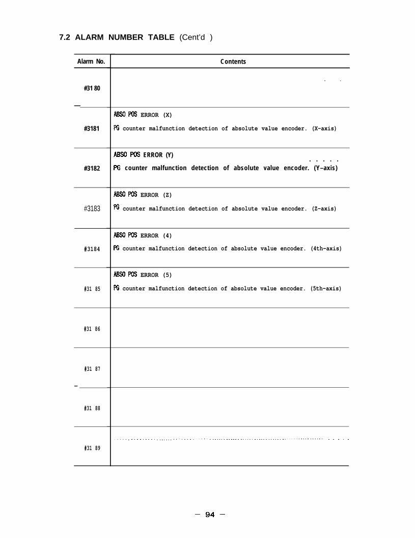
7.2 ALARM NUMBER TABLE (Cent’d )
Alarm No.
#31 80
—
#3181
#3182
#3183
#3184
#31 85
#31 86
#31 87
—
#31 88
#31 89
Contents
. .
ABSOPOS ERROR (X)
PG counter malfunction detection of absolute value encoder. (X–axis)
ABSOPOS ERROR (Y). . . . .
PG counter malfunction detection of absolute value encoder. (Y–axis)
ABSOPOS ERROR (Z)
PG counter malfunction detection of absolute value encoder. (Z–axis)
ABSOPOS ERROR (4)
PG counter malfunction detection of absolute value encoder. (4th–axis)
ABSOPOS ERROR (5)
PG counter malfunction detection of absolute value encoder. (5th–axis)
. . . . . . . . . . . . . . . . ------ . . . . . . . . . . . . . . ------ ------ ------ ------ ------ ------ ------ ------ . . . . .
–94–

Alarm No. Contents
. . . . . . . . . .#3190
. . . . . . . . . . . . ------ . . . . . . . . . . . . . . . . . . . . . . . . . . . . . . . . ------ . . . . . . . . . . . . . . . . .#3191
. . . . . . . . . . . . . . . . . . . . . . . . . . . . . . . . . . . . . . . . . . . . . . . . . . . . . . ------ . . . . . . . . . . . . . ------#31 92
. . . . . . . . .
. . . . . . . . . . . . . . . . . . . . . . . ------ ------ . . . . . . ------ ------ ------ ------ ------ ------ ------ ------#3193
. . . . . .#31 94
#3195
#3197
l-----------------------------.--.-------------------`-""-"--""""-'"""""""""-""-""""-------#3198
–95–

7.2 ALARM NUMBER TABLE (Cent’d)
Alarm No.
#3200
#3201
#3202
#3203
#3204
#3205
#3206
#3207
#3208
.—
#3209
Contents
. . . . . . . . . . . . . . . . . . . . . . . . . . . . . . . . . . . . . . . . . . . . . . . . . . . . .
. . . . . . . . . . . . . . . . . . . . . . . . . . . . . . . . . . . . . . . . . . . . . . . . . . . . . . . . . . . . . . .
. . . . . . . . . . . . . . . . . . . . . . . . . . . . . . . . . . . . .
. . . . . . . . . . . . . . . . . . . . . . . . . . . . . . . . . . . . . . . . . . . . . . . . . . . . . . . . . . . . . . . . . . . . . . . .
. . . . . . . . . . . . . . . . . . . . . . . . . . . . . . . . . . . . . . . . . . . . . . . . . . . . . . . . . . . . . . . . . . . . . . . . .
–96–
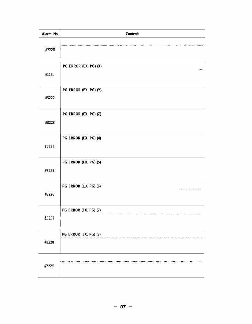
Alarm No. I Contents
PG ERROR (EX. PG) (X). . . . . . .
#3221
PG ERROR (EX. PG) (Y)
#3222
PG ERROR (EX. PG) (Z)
#3223
PG ERROR (EX. PG) (4)
#3224
PG ERROR (EX. PG) (5)
#3225
PG ERROR (EX. PG) (6)
#3226. . . . . . . . . . . . . . . . . . .
PG ERROR (EX. PG) (7)}-------------------------------------------------------------------------------------------------------------------------
PG ERROR (EX. PG) (8). . . . . . . . . . . . . . . . . . . . . . . . . . . . . . . . . . . . . . . . . . . . . . . . . . . . . . . . . . . . . . . . . . . . . . . . . . . . . . . . . . . . . . . . . . . . . . . . . . . . . . . .
#3228
–97–

7.2 ALARM NUMBER TABLE (Cent’d )
Alarm No.
#3240
#3241
#3242
#3243
#3244
#3245
#3246
#3247
#3248
#3249
Contents
*OUENCE ERROR 2
Sequence error 2. Servo off.
.
.
–98–

Alarm No. Contents
#3250
#3252
#3253 l"-------"""""""""""""""--'""---""---"-"""""""""-"""""--"""`-""---"""`"""-""""-"""-""--""""'""""""""""I
#3254
l------------" '--"` --"`" ""-"" "-""" """"` """'` """"` """"" "-"-""""""""""""'""-"""""""""""""""""""-'""`""""#3255
#3257
#3259
–99–

7.2 ALARM NUMBER TABLE (Cent’d )
Alarm No.
#3260
#3261
#3262
#3263
#3264
#3265
#3266
#3267
#3268
#3269
Contents
=–INTEX SYNC ERROR. . . . . . . . . . . . . . . . . . . . . . . . . . . . . . . . . . . . . . . . . . . . . . ------ ------ ------W–INTEX synchronization error.
W–W SYNC ERROR
~–m synchronization error.
M–MG SYNC ERROR
W–M synchronization error.
W–PLC SYNC ERROR
W–~C synchronization error.
ffi-AX I S SYNC ERROR
M–AXIS synchronizat ion er ror .
ACGC SYNC ERROR
ACGC synchronization error.
UNC SYNC ERROR
ONC synchronization error.
. . . . . . . . . . . . . . . . . . . . . . . . . . . . . . . . . . . . . . . . . . . . . . . . . . . . . . . . . . . . . . . . . . . . . . . . . . . .
– 100 –

Alarm No. I Contents
POWER OFF ERROR (KEEP MEM)
#3270 Data error which is principally a system error when power is turnedo f f .
IPOWER O F F E R R O R ( T O O L L I F E)l----- .-------- .-... ------- . ..---- . . ..---- .-.. ---.....--------"""""""""""""""""""""----"""""""-
#3271 I~;a error which is principally a system error when power is turned
1---------------------------------------POWER OFF ERROR (MACRO)
#3272 Data error which is principally a system error when power is’turnedoff.
POWER OFF ERROR (WORK MEM)l-. -------. --------------- """" -"--" "-"-" -----" -""" -"""""""""""""""""""""-----"-"""""""'""""""`'-
#3273
#3274
Data error which is principally a system error when power is turnedo f f .
POWER OFF ERROR (PRMRAM). . .
Power off during editting breaks down the program.Error is released by power off/on operation after deleting thedestructive program.
PROGRAM CHECK REQUIRED
#3275 Program check is required after power on because of the power offduring editting.
#3276
. .
#3277
#3278
#3279
– 101 –

7.2 ALARM NUMBER TABLE ( @nt’d)
Alarm No. Contents
#3280
AXIS ERROR 1
#3281 AXIS error 1.
I
AXIS ERROR 2
#3282 AXIS error 2.
AXIS ERROR 3
#3283 AXIS error 3.
I MIS ERROR 41------------------------------ ---. ----------" """"" '""""-"-""-""""""---"""""""""---""'""""--"""-"
#3284 AXIS error 4.
AXIS ERROR 5
#3285 AXIS error 5.
i
#3286
#3287
. . . . . . . . . . . . ..- --------------- --------------- --------------- .#3288
. . . . . . . . . . . . . . . . . . . . . . . . . . . . . . --------------- --------------- -----
#3289
– 1 0 2 –

Alarm No. Contents
#3290
#3291
#3292
#3293
#3294
#3295
. . . . . . . . . . . . . . . . . . . . . . . . . . . . . . . . . . . . . . . . . . . . . . . . . .#3296
#3297
#3298
. . . . . . . . .#3299
. . . . . . . . . . . . . . . . . . . . . . . . . . . . . . . . . . . . . . . . . . . . . . . . . . . . . . . . . . . . . . . . . . . . . .
– 103 –

7. 2 ALARM NUMBER TABLE (Cent’d)
Alarm No.
#3300
#3301
#3302
#3303
#3304
#3305
#3306
#3307
#3308
#3309
Contents
OVERCUF4RENT ( X )
Overcurrent occurred in servo pack main circuit. (X–axis)
OVERCURRENT (Y). . . . . . . . . . . . .Overcurrent occurred in servo pack main circuit. (Y–axis)
OVERCURRENT (Z)
Overcurrent occurred in servo pack main circuit. (Z–axis)
OVERCURRENT (4)
Overcurrent occurred in servo pack main circuit. (4th axis)
OVERCURRENT (5)
Overcurrent occurred in servo pack main circuit. (5th axis)
. . . . . .
. . . .
– 1 0 4 –

Alarm No. Contents
. . . . .#331 o
MCCB TRIP (X)
#331 1 Servo pack MCCB was tripped. (X–axis)
MCCB TRIP (Y)
#331 2 Servo pack MCCB was tripped. (Y–axis)
MCCB TRIP (Z)
#3313 Servo pack MCCB was tripped. (Z–axis)
MCCB TRIP (4).
#3314 Servo pack MCCB was tripped. (4th axis)
—. —MCCB TRIP (5)
#331 5 Servo pack MCCBwas tripped. (5th axis)
. . . . . . . . . . . . . . . . . . . . . . . . . . . . . . . ------ ------ ------ ------ ------ ------ ------ ------ ------ --#3316
.—
. . . . . . . . . . . . . . . . . ------ ------ ------ ------ ------ ------ ------ -- .--’ ------ ------ ------ ------ ------#331 7
. . . . . . . . . . . . . . . . . . . . . . . . . . . . . . ---------- ---------- ---#3318
#331 9
– 1 0 5 –

7.2 ALARM NUMBER TABLE (Cent’d )
Alarm No.
#3320
#3321
#3322
#3323
#3324
#3325
#3326
#3327
#3328
#3329
Contents
. .
REGENERATIVE ERROR (X)
Error occurred in servo pack regenerative reSiStOr. (x–axis)
REGENERATIVE ERROR (Y)
Error occurred in servo pack regenerative resistor. (Y—axis)
REGENERATIVE ERROR (Z)
Error occurred in servo pack regenerat
REGENERATIVE ERROR (4)
Error occurred in servo pack regenerat
v e r e s i s t o r . ( Z – a x i s )
ve res is tor . (4 th ax is )
REGENERATIVE ERROR (5;
Error occurred in servo pack regenerative resistor. (5th axis)
. . .
. .
– 106 –

Alarm No. ] Contents
#3330
OVERVOLTAGE (X). . . . . . . . . . . . . . . . . . . . . . . . . . . . . . . . . . . . .
#3331 Servo pack main circuit DC voltage is abnormally high. (X–axis)
OVERVOLTAGE (Y). . . . . .
#3332 Servo pack main circuit DC voltage is abnormally high. (Y–axis)
P"""""'"""""""'""""""""""""""'"""""""""""`"""""""""""""--"-"--"Servo pack malnclrcutt DC v o l t a g e is abnormal lyhtgh. ( Z – a x i s )
OVERVOLTAGE (4)
#3334 Servo pack main circuit DC voltage is abnormally high. (4th axis)
OVERVOLTAGE (5)
#3335 Servo pack main circuit DC voltage is abnormally high. (5th axis)
#3337
. . . . . .#3338
#3339
– 1 0 7 –

7.2 ALARM NUMBER TABLE (Cent’d)
Alarm No.
#3340
#3341
#3342
#3343
#3344
#3345
#3346
#3347
#3348
#3349
C o n t e n t s -
UNDERVOLTAGE (X)
Servo pack main circuit DC voltage is abnormally low. (X–axis)
U N D E R V O L T A G E ( Y ). . . . . . . . . . . . . . . . . . . . . . . . --%rvopackm ain circuit DC voltage is abnormally low. (Y–axis)
UNDERVOLTAGE (Z)
Servo pack main circuit DC voltage is abnormally low. (Z–axis)
UNDERVOLTAGE (4) . . . .Servo pack main circuit DC voltage is abnormally low. (4th axis)
UNDERVOLTAGE (5) . . . . .Servo pack main circuit DC voltage is abnormally low. (5th axis)
– 1 0 8 –

Alarm No. I Contents
#3350
#3351
HEAT SINK OVERHEAT (X)
servo pack heat sink was overheated. (X–axis)
#3352
#3353
HEAT SINK OVERHEAT (Y)
Servo pack heat sink was overheated. (Y–axis)
HEAT SINK OVERHEAT (Z). .
%rvopackh eat s ink was overheated. (Z–ax is )
#3354
HEAT SINK OVERHEAT (4)
Servo pack heat sink was overheated. (4th axis)
#3355
HEAT SINK OVERHEAT (5)
Servo pack heat sink was overheated. (5th axis)
#3356
#3357
. . . . . . . . . . . . . .
. . . . . . . . . . .
#3358
#3359
– 1 0 9 –

7.2 ALARM NUMBER TABLE (Cent’d )
Alarm No. I Contents
#3360
---*:*!LE.!!FEN.Jx)- . . . . . . . . -------#3361 Break in current command cable between YASNAC and servo pack.
( X – a x i s )
t–––––CURRENT CWANDCABLEBRDKEN (Y)l . . - - - - - - - - - - - - - - - - - - - - - - - - - - - - - - - - - - - - -
#3362 Break in current comand cable between YASNAC and servo pack.( Y – a x i s )
‘“--:;-””””””’”””””””’””””’””””””””””’””””””””Break !n current command cable between YASNAC and servo pack.
CURRENT CNAND CABLE BROKEN (4)
#3364 Break in current comand cable between YASNAC and servo pack.(4th axis)
I C U R R E N T CMAND CABLE BROXEN (5 )l-.. ------------------ .--. ------ . ..------ """"" """"" "'"""""""`""""""-"""""""""""""""""""""""""""""""
#3365 Break in current comand cable between YASNAC and servo pack.(5th axis)
#3366
—.
#3367. . . . . . . . . . . . . . . . . . . . . . . . . . . . . . . . . . . . . . . . . . . . . . . . . . . . . . . . . . . . . . . . . . . . . . . . . . . . . . . . . . . . . . . . . . . . .
#3368
#3369
–llo–
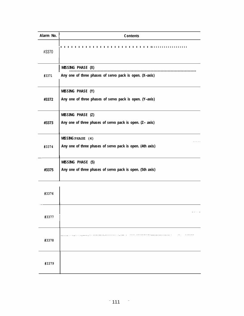
Alarm No. I ContentsI
I. . . . . . . . . . . . . . . . . . . . . . . . . .. . . . . . . . . . . . . . . . . .
#3370
I MISSING PHASE (X)l - - - - - - - - - - - - - - - - - - - - - - - - - - - - - - - - - - - - - - - - - - - - - - - - - - - - - - - - - - - - - - - - - - - - - - - - - - - - - - - - - - - - - - - - -
#3371 Any one of three phases of servo pack is open. (X–axis)
MISSING PHASE (Y)
#3372 Any one of three phases of servo pack is open. (Y–axis)
MISSING PHASE (Z)
#3373 Any one of three phases of servo pack is open. (Z– axis)
MISSING PHASE (4) . . . . .#3374 Any one of three phases of servo pack is open. (4th axis)
—MISSING PHASE (5)
#3375 Any one of three phases of servo pack is open. (5th axis)
#3376
—
. . . . .
#3377 I
. . . . . . . . . . . . . . . . . . . . . . . . . . . . . . . . . . . . . . . . . . . . . . . . . . . . . . . . . . . . . . . . . . ------------ ------------ ------------
#3378
#3379
– 111 –

7.2 ALARM NUMBER TABLE (Cent’d)
Alarm No. Contents
#8000
SYSTEM VERSION UNMATCH
#8002 ROM version number of C~ is not match.
#8003
#8004
——
#8007
I
– 1 1 2 –

Alarm No. Contents
l--------------------------------------------------------------#9000
#9001
#9002
. . . . . . . . . . . . . . . . . . . . . . . . . . . . . . . . . . . . . . . . .#9003
. . . . . .
#9004
#9005l"""""""""" -""""""" -"-"""""""" -""-"-""""""" -""""""" -------""""""""""" ---""-""""""""" --"-""-""---""
. . .
1
#9007
I. . .#9008. . . . . . . . . . . . . . . . . . . .
#9009. . . . . . . . . . . . . . . . . . . . . . . . . . . . . . . . . . . . . . . . ------- ------- . .
– 113–

7.2 ALARM NUMBER TABLE (Cent’d )
Alarm No. I Contents
TH ERROR
#9010 TH Parity.
TV ERROR
#901 1 TV Parity.
I ILLEGAL CHARACTERl------------ ..-... -.------- .---. ---------- .------ .--. -------------------------------.--------'
#9012 There are characters that cannot be used other than as lSO/EIA codewith RS–232C.
1 BLOCK LENGTH ERROR
#9013 One block over capacity (128 characters) was detected in RS–232C.
DATA SET READY DOWN. .
#9014 No response from DATA SET READY signal in RS–232C.
NMRIC DATA OVERFLOW
#9015 Numerical value overflow of input data. (exceeds 9 characters)
RS–232C ERROR (SIGNAL LEVEL) . . .
#9016 RS–232C interface transmission abnormal.
RS–232C ERROR (OVER RUN)
#9017 Over 10 characters read after RS–232C interface stop code OUT.
RS–232C ERROR (CH SELECT)
#9018 Error in se lect ion of RS–232C inter face c i rcui t .
I RS-232C ERROR (FRAMING)l---. --------. -----------------------. ---"" --""' """" --"-" """"" "---" """-" -`""' "-"" --""" """"" """--""
#9019 Error in RS–232C interface framing.(Improper stop-bit setting or transmission error.)
– 114–

Alarm No. I Contents
#9020
#9021
RS–232C ERROR (APL– 1 )
Specified Iinewas already open.
RS–232C ERROR (APL– 2)
Specified line is still not Open..
l---------------------------------------------------------------------RS– 232C ERROR (APL– 3)
#9022 Correct combination of dual core is not being used.
RS–232C ERROR (APL–4)
#9023 Transmission was not conducted during the specified time.
#9024
#9025
RS– 232C ERROR (APL– 5)
Sending or receiving start processing not conducted.
RS– 232C ERROR (APL– 6)
Error in specified parameter.
#9026
#9027 l"`""""""""--"-""""""""-"""-'""""""'""""""""--""""""""""---"-"-"--"--""-"--""""""""""""""""""-""""
#9028
.
#9029
–115–

7.2 ALARM NUMBER TABLE (Cent’d )
Alarm No.
#9030
—
#9031
#9032
#9033
#9034
#9035
#9036
#9037
#9038
#9039
Contents
. . . . . . . . . . . . . . . . . . . . . . . . . . . . . . .
. . . . . . . . . . . . . . . . . . . . . . . . . . . . . . . . . . . . . . . . . . . . . . . . . . . . . . . . . . . . . . . . . . . . . . . . . . .
. . . . . . . . . . . . . .
–116–

Alarm No. Contents
#9040
#9041
#9042
. . . . .#9043
#9044
#9045
#9046
#9047
#9048
#9049

7.2 ALARM NUMBER TABLE (Cent’d )
Alarm No.
#9050
#9051
#9052
#9053
#9054
#9055
#9056
#9057
#9058
#9059
Contents
. . . . . . . . . . . . . . . . . . . . . . . . . . . . . .
. . . . . . . . . . . . . . . . . . . . . . . . . . . . . . . . . . . . . . . .
. . . . . . . . . . . . . . . . . . . . . . . . . . . . . . . . . . . . . . . . . . . . . . . . . . . . . .
. . . . . . . . . . . . . . . . . . . . . . . . . . . . . . . . . . . . . . . . . . . . .
. . . . . . . . . . . . . . . . . . . . . . . . . . . . . . . . . . . . . . . . . . . . . . . . . . . . . . . . . . . . . . . . . .
. . . . . . . . . . . . . . . . . . . . . . . . . . . . . . . . . . . . . . . . . . . . . . . . . . . . . . . . . .
– 118–

8. G CODEB : BasicO : Option
G CODE
GOO qGO1 T
G02
G03
G04G06G09
G1O
G12G13G17\G18G19G20G21G22G23G25G27G28G29G30G31G40 7G41G42G43 \G44 \G49 \G45G46G47
G 4 8G50 q—.G51
G52 ‘—
G53G54G55G56G57G58G59
Group Function Classification
Positioning (Rapid feed) BLinear interpolation B
01 Circular interpolation CW,Helical interpolation CW B, O
Circular interpolation CCW,Helical interpolation CCW B, O
Dwell BError detect off positioning BExact step B
* Tool offset amountSetting of work coordinate shift amount
B, O
Circle cutting CW oCircle cutting CCW oXY plane specification B
02 ZX Plane specification BYZ plane specification B
06INCH input specification BMM input specification B
04 Stroke limit ON oStroke limit OFF oProgram copy oReference point return check BReference point return B
*Return from reference point BSecond, third and fourth reference point returns B, OSkip function oTool radius offset cancel o
07 Tool radius offset, left oTool radius offset, right oTool length offset in + direction B
08 Tool length offset in – direction BTool length offset cancel BTool position offset extension BTool position offset reduction B
*Tool position offset double extension BTool position offset double reduction B
15 Scaling OFF oScaling ON oReturn to reference coordinate system,12 local coordinate system
o
* Machine coordinate system specification oShift to Work Coordinate System 1 BShift to Work Coordinate System 2 0Shift to Work Coordinate System 3 0
12Shift to Work Coordinate System 4 0Shift to Work Coordinate System 5 0Shift to Work Coordinate System 6 0
–119–

B : BasicC : Option
G CODE
G60G61G6F—G65G66G67 7G68G69 qG70G71G72G73G74676G77G80 -G81G82G83G84G85G86G87G88G89G90 \G91 ‘G92G93G94 qG98 ‘G99
G106G181G182G183G184G185G186G187G188G189
Group Function Classification
01 Unidirectional positioning oExact Stop mode B
13 Exact Stop mode cancel B* Simple call of microprogram o
Microprogram modal call o14
Microprogram modal call cancel oCoordinate rotation ON o
18 Coordinate rotation OFF o
}
Fixed09 F
FF
q0. 1. The symbol ~ indicates code will be selected automatically when power is
switched ON or when reset.2. The symbol ~ indicated code will be selected automatically when power is
switched ON.3. If more than one ~ or ~ is liste~ for a single group, one of the codes
marked as such is selected according to parameter setting.
– 12Q –

9. PARAMETER
9.1 PARAMETER NUMBER LIST
No
1
2
3
4
5
6
7
8
9
Classification Datatype Parameter No. symbol Valid with Remarkspower off
Bit #oooo to #oo99
Byte #oloo to #olo9jetting-related
Word #0400 to #0429 with
D Word #0800 tO #0939 with
%xis system control-related Bit #looo to #lo99 #lo20 to #lo99
I
Axis control Byte #lloo to #1399 #1300 to #1399
Servo Word #1400 to #1799 with #1600 to #1799
Spindle D Word #1800 to #1859 with #1820 to #1859
?eed-related Bit #2000 to #2019
[
Speed, acceleration Byte #2100 to #2139
Screw/tap Word #2400 to #2649 #2600 to $2649
Handle D Word #2800 to #2899 #2870 to #2899
Iuman I/F communications-related Bit #3000 to #3009
[
Editing/tape input Byte #3100 to #3109
Display Word #3400 to #3459 with
Communication/DNC D Word #3800 to #3859 with
Program/Automatic operation-related Bit #4000 to #4039
[
Program /autmatic operation Byte #4100 to #4199Canned cycleCorrection/coordinate system Word #4400 to #4599 with
Home position return/macro D Word #4800 to #4899 with
Input-output/Automatic support-related Bit #5000 to #5019 #5010 to #5019
[
1/0 Byte #5100 to #5109PLCSkip Word #5400 to #5449 with
TLM D Word #5800 to #5809 with
Machine support safety/maintenance- ‘ i t #6000 to #6009related Byte #6100 to #6149
[
Stroke check Word #6400 to #6479 with #6450 to #6479Pitch error D Word #6800 to #6949 with
Bit #7000 to #7099 Byte also possible.PLC ladder, keep memory-related Byte and word
Byte #7100 to #7999 possible.
Bit #8000 to #8009
Byte #8100 to #8119Other
Word #8400 to #8429 with
D Word #8800 to #8829 with
Word #9000 to #9511
– 121 –

9.1 PARAMETER NUMBER LIST (Cent’d)
Parameter number Index (Alphabetical order)
The axes parameters below are represented by X–axis parameter numbers.
(A)
Absolute value encoder (X-axis). #1044 (D4)Accel/decel speed constant of regular cutting (X-axis to 5th axis). #2501
Accel/decel speed constant when thread cutting/tapping (X-axis to 5th axis). #2511
Addition of amount of work coordinate shift correction. #0007 (D3)
Added axis be disregarded ? #6000 (D6)
Accel/decel speed time constant (main axis). #2471
Advance read stop M code. #4400
Alarm occur if cycle starts without returning to reference point once afterswitching on the power. #4018 (DO)
Alarm occur when starting, without resetting after program editing operation ? #4001 (D7)Amount of movement per motor revolution (X-axis to 5th axis). #1821Amount of override in G60(X-axis to 5th axis). #4461Amount of return with G73. #0870Amount of return with G83. #0871Amount of TLM bias. #0806Automatic axis naming system. #1142Automatic coordinate setting (X-axis to 5th axis). #4006 (DO)Automatic coordinate system setting value during inches input. #4811
Automatic coordinate system setting value during millimeters input(X-axis to 5th axis). #4801
Automatic handle offset possible, area. #2003 (Dl)
Automatic mode HANDLE OFFSET switch. #0005 (D3)
Automatic series of all axes names. #1169
Auxiliary function lock switch. #0000 (D5)
Axis display name. #lloo
Axis removal specification (X-axis to 5th axis). #6006 (DO)
(B]
Backlash sub offset. #1701
Backlash offset. (X-axis to 5th axis) #1551
Block delete switch. #0000 (D3)
Buzzer sound (Operator panel). #0007 (D7)
[c]
CallCallCallCallCall
M code (1 to 24) of M code macro. #4504
program No. (1 to 24) of G code macro. #4840
program No. (1 to 24) of M code macro. #4864
specification of B code macro (1 to 24). #4890
specification (1 to 24) of T code macro (1 to 24). #4889
Change point of correction amount.Changeover point of correction direction.
#4013 (D2)#4013 (Dl)
– 1 2 2 –

Check of speed matching signal(lst axis to 5th axis).Circle cutting speed in high speed section.Clearing of program No. when switching on the power.Code conversion of ISO code during tape input.Coordinate value when SKIP signal operating (lst axis to 9th axis).Corner block division.Correction startup and cancel operation.Count in parenthesis of TV check.Cutting feed linear accel/decel speed constant (X-axis to 5th axis).Cutting accel/decel speed bias (X-axis to 5th axis).Cycle start signal.
(D]
Data type of external data input.Delay time before checking spindle speed attainment signal (SAGR).Detection of GOO error in solid tap.Direction of rotation of servo control system motor.Display lock switch.‘Drift correction (X-axis).DRY RUN switch.Dry run during thread cutting.Dry run of rapid traverse command.Dual time of G76/G77.
( E )
Edit, display and output of part program of program numbers 9000 to 9999.Editing inhibit switch.EF signal output with G81.Effective command system (Ist axis to 5th axis).EOB code with CR during 1S0 code output.Error allowable range when specifying circular R.Error cut during emergency stop input (X-axis).Error detect ON area (X-axis to 5th axis).Error detect ON area during loop control.Error detection at end of dwell execution.Executing stroke check first inhibited area? (X-axis to 5th axis).Expansion address P or J in work coordinate setting.External timer display.
#1058 (DO)#2862#3005 (Dl)#3005 (D5)#0811#4013 (D5)#4013 (DO)#0004 (D2)#2581#2821#5000 (DO)
#5001 (DO)#1540#4015 (D5)#1030 (D7)#oooo (D6)#lo45 (D6)#0000 (D2)#2000 (Dl)#2000 (DO)#4017 (D3)
#3004 (DO)#0000 (D7)#4016 (DO)#1004 (DO)#ooo4 (D6)#4820#1044 (D2)#1321#1331#4015 (D3)#6002 (DO)#4012 (D7)#3001 (DO)
– 123 –

9.1 PARAMETER NUMBER LIST (Cent’d)#
[ F )
F1 digit speed(Fl to F9).F1 digit switch.Feed during tape output.Feed override signal (Point A).Feedrate (O to 31 )corresponding to the JOG feedrate selection switch positionFeedrate during skip function.Feedrate during skip function.Feedrate filter time constant (X-axis to 5th axis).First step of rapid traverse accel/decel speed time constant.(X-axis to 5th axis).Followup processing in servo OFF input (X-axis).Form correction coefficient (01 to 09, 11 to 19).F speed unit setting with 1/10.
( G ]
G code default value (When switching on power or resetting).
G code (1 to 24) macro call.G45 to G48 correction No. command code.G60 unidirectional positioning direction (X-axis to 5th axis).G76/G77 dwell time.Gear No. for spindle loop control.
[ H ]
Handle multiplying factor X 100 selection multiplying factor.Handle accel/decel speed constant (X-axis to 5th axis).High speed/low speed changeover of automatic reference point return.High speed automatic start in high speed rewind.High speed mode operation address name (4th axis to 5th axis).Hole pattern of EIA code used in user macro.
[1)
In-position wait with the GOO and GO1 + GOO command.Input device specification.Input port specification.Input unit mm/inch.Intermediate pot display.Internal M code of initial state (When switching on power or resetting).Internal system number switch setting.
Internal toggle switch.Interruption check function (radius compensation).Is alarm to be set when executing move command other than G28 withoutconducting reference point return ?Is alarm to be set when cycle starts without reference point return?Is change of amount of work coordinate shift to be immediately valid?
#0820#ooo5 (D6)#0004 (D4)#2000 (D4)#2400#2001 (DO)#2001 (Dl)#2591
#2461#1044 (D3)#1801#2004 (DO)
#4000 (DO)#4480#4011 (Dl)#4014 (DO)#0400#1260
#2003 (D7)#2561#4003 (D7)#4008 (D7)#1201#4100
#4015 (D4)
#0010 (DO)#0009 (DO)#0007 (DO)#3001 (D5)#4001 (DO)#olo9#5001 (Dl)#4013 (D3)
#4004 (DO)
#4001 (D6)#4012 (DO)
– 1 2 4 –

( J ]
JOG feedrate parameter numerical value multiplying factor.
[ M )
M Code when outputting with G84.M05 output at the bottom of the hole of G74, G84.M05 output prior to M19 output with G76/G77.Machine lock switch.Macro interlock editing, display and output (O 8000 level)Macro interlock edit inhibit (O 8000 level).Macro interlock edit inhibit (O 9000 level).Make JOG speed of rotating axis 1/10 of linear axis?Make valid immediately when amount of offset changes?Manual 2nd reference point return switch.Manual absolute function (relative to increment commands).Manual absolute switch.Manual movement amount (Reset, reference point return, G92, key setup, etc.).Manual reference point return switch.Maximum cutting feedrate (rotation axis).Maximum cutting feed speed (linear axis).Maximum feedrate of F1 digit(Fl to F9) command.Maximum feedrate of handle linear spindle.Maximum feedrate of the handle rotating spindle.Maximum rotation relative to 10V spindle command.Maximum spindle speed in spindle solid tap.Measuring method of TLM.Minimum input X 10.Minute circular skip value.Mirror image (X-axis to 5th axis).Mirror image applied to intermediate point with G28 command during mirrorimage operation ?Motor revolutions during spindle GRS input.Motor revolutions during spindle GSC input.MST processing when changing mode.Multiple relative to spindle error area rapid traverse rate.Multiplying factor of handle feed X 100.Multiplying factor setting of feedback pulse (X-axis).
#2432
#4016 (D2)#4016 (D3)#4017 (Dl)#0000 (Dl)#0020 (DO)#0021 (DO)#0022 (DO)
#2000 (D7)#4010 (DO)#0005 (Dl)#4011 (D7)#0000 (D4)#4011 (D6)#0005 (DO)#2810#2800#2865#2860#2861#1415#1416#6008 (DO)#1000 (DO)#4450#ooo2
#4001 (D2)#1413#1412#4009 (D7)#1351#2459#1044 (DO)
– 125 –

9.1 PARAMETER NUMBER LIST (Cent’d)
[N]
Negative direction of external deceleration (X-axis to 5th axis).Number of high speed mode operation control axes.Number of pulses per revolution of PG (X-axis to 5th axis).Number of teeth of Gear A on the spindle side usable in solid tap.Number of teeth of the intermediate gear of Gear B usable solid tap.Number of teeth of the spindle intermediate gear of Gear A usable in solid tap.Number of teeth on the motor side of Gear A usable in solid tap.Number of teeth on the motor side of Gear B usable in solid tap.Number of valid servo axes.Number of valid spindle axes.Number of teeth of the motor intermediate gear of Gear A usable in solid tap.Numerical value of program number.
[0]
Offset of automatic mode handle.One graduation feed speed change of F1 digit specified manual pulse generator.Operating mode specification of high speed mode operation.Operation expression of direct input operation of work piece measurement value.Optional stop switch.Output device specification.Output of leading O when high order variable of D’PRINT function is O.Output port specification.
[P]
Peak value display of synchronous error of the spindle and Z–axis duringsolid tap.Pitch dwell time (Canned cycle G73).Pitch dwell time of G83.Pitch error offset incremental/absolute.Pitch error offset interval (X-axis to 5th axis).Pitch error offset multiplying factor (X-axis to 5th axis).Pitch error end memory No. (X-axis to 5th axis).Pitch error reference point memory No. (X-axis to 5th axis).Pitch error start memory No. (X-axis to 5th axis).Pitch error valid/invalid (X-axis to 5th axis).Playback switch.Position at which JOG feedrate parameter is increased 10 times.Position at which JOG feedrate parameter value is reduced to 1/10.Positioning operation of canned cycle (GOO or GO1).Positive direction of external deceleration (X-axis to 5th axis).Preset of work coordinate shift (When power switched on).Preset of work coordinate shift (When reference point return is completed).
#5004 (DO)#1200#1831#1841#1515#1511#1513#1514# 1300#1301 (DO)#1512#3005 (D2)
#2002 (DO)
#2111#4160#4010 (D2)#0001 (DO)#0010 (D4)#4009 (D2)#0009 (D4)
#4015 (D6)#4017 (D4)#0401#6001 (DO)#6801#6101#6411#6421#6401#6000 (DO)#0005 (D5)#2433#2434#4016 (Dl)#5002 (DO)#4001 (D3)#4001 (D4)
– 126 –

[ P ]
Processing during interruption check (diameter correction).Processing interruption point return switch.Processing when O number already exists during tape load.ProgramProgramProgram
(R]
end of end M code during tape load.restart approach speed.restart switch.
Rapid feedrate of external deceleration.Rapid traverse override rate (FO to F2).Rapid traverse rate (X-axis to 5th axis).Rapid traverse rate until completion of first reference point return afterswitching on the power.Reference point position (2nd to 4th).Reference point return (X-axis to 5th axis).Reference point return approach speed (X-axis to 5th axis).Reference point return creep speed (X-axis to 5th axis).Reference point return direction (X-axis to 5th axas).Reference point return travel distance (X-axis to 5th axis).Reset operation of macro common variable #100 to #299.Reset output when emergency stop input is ON.Return to setup point.Rewind of NC program with a rewind signal.Rewind with M30 when RS232C YASNAC standard tape reader is connectedRS232C general purpose inputRS232C general purpose inputRS232C general purpose input
RS232C general purpose inputRS232C general purpose inputRS232C general purpose inputRS232C general purpose inputRS232C general purpose input
NC intrinsic data control (First).control-code control (First ).bit length (First).BPS setting (First).DR line control (First).parity bit (First).RTS control (First).stop bit (First ).
RS232 C general purpose output bit length (Second).RS232C general purpose output BPS setting (Second).RS232C general purpose output control-code control (Second).RS232C general purpose output DR line control (Second).RS232C general purpose output NC intrinsic data control (Second).RS232C general purpose output parity bit (Second).RS232C general purpose output RTS control (Second).RS232C general purpose output stop bit (Second).
#4013 (D4)#0005 (D2)#3005 (DO)#3005 (D3)#4015 (D7)#0005 (D7)
#2444#2447#2801
#2000 (D6)#6811#4022 (DO)#2521#2531#4002#4451#4009 (Dl)#5000 (D2)#0005 (D4)#5000 (Dl)#4008 (Dl)#0012 (D7)#0012 (DO)#0011 (D4)#0011 (DO)#0012 (D2)#0011 (D5)#0012 (Dl)#0011 (D3)#0013 (D4)#0013 (DO)#0014 (DO)#0014 (D2)#oo14 (D7)#0013 (D5)#0014 (Dl)#0013 (D3)
– 1 2 7 –

9.1 PARAMETER NUMBER LIST (Cent’d)
[s]
S code macro call specification (1 to 24)S output symbol (M03/M04).Saving of D code when resetting.Saving of H code during reference point return when resetting.Scaling multiplying factor setting (numerator).Scaling multiplying factor setting (denominator).Segment type of high speed mode operation.Sequence number setting of break point.Servo control system linear axis/rotating axis (X-axis).Servo control system servo control (X-axis).Servo power ON.Servo spindle No. for solid tap.Shift angle during G76 and G77 commands.Shift speed of canned cycle G76 and G77.Significant number of systems.Single block in a user macro program.Single block switch.SKIP signal ON.SKIP signal polarity.SKIP signal valid/invalid.Slot spindle information (Ist to 6th).Solid tap return speed multiplying factor.Solid tap servo axis interrupt in-position width.Solid tap synchronization correction parameter.Specified section end code of operating mode of high speed mode operation.Specified section start code of operating mode of high speed mode operation.Speed during skip operation.Speed in relation to cutting feed of external deceleration.Spindle display name.Spindle feed back pulse multiple setting.Spindle gear range maximum rotations.Spindle gear range minimum rotation clamp.Spindle gear range motor maximum rotation clamp.Spindle indexing confirmation timer.Spindle indexing creep speed.Spindle indexing during loop control.Spindle indexing start speed.Spindle indexing stop confirmation rotations.
#4888#1001 (DO)#4010 (D6)#4010 (D7)#0803#0804#4167#0801#lo30 (D6)#1030 (D5)#5012 (DO)#1241#0805#2864#1318#0007 (Dl)#0000 (DO)#0007 (D2)#5011 (DO)#5010 (DO)#1020 (DO)#1252#1500#1502#4164#4161#2440#2445#1127#lo53#1404#1400#1408#1220#2546#1053 (D2)#2541#1225
– 128 –

[sj
Spindle matching check when changing from rapid feed to cutting feed.Spindle No. for solid tap.Spindle output sequencer loop.Spindle override percentage.Spindle override when executing G84, G74 tab cycle.Spindle override 100% clamp when tapping.Spindle position loop gain.Spindle rotation parameter multiple X 10.Spindle servo control system PG (main axis).Spindle servo control system servo control (main axis).SSTP polarity when spindle S command input-output is O.START LOCK swich.Stored stroke limit inhibited area.Stored stroke limit inside/outside inhibited.Stored stroke limit minus (X-axis to 5th axis).Stored stroke limit plus (X-axis to 5th axis).Stored stroke limit switch axis No. (2nd to 5th).Stored stroke limit valid/invalid. (2nd to 5th). ,Stroke monitor (X-axis).Symbol of incremental input of amount of work coordinate shift.
[ T )
Tape code output (ISO/EIA).TG (X-axis).TH check during 1S0 code input.TH check during ISO code output.Threading cutting variable speed bias (X-axis to 5th axis).Time from clearing of base block to release of brake when servo power isswitched on.Time from falling of emergency stop to base block OFF.Time from sending M, S, T codes to sending of MF, SF, and TF .Title display first line.Title display multiplying factor.Title display second line.Title display start position.TLM bottom level.Tool pot display No..TV Check.Types of rapid traverse overrides.
(u]
Universal position display by coordinate settings.Unslotted servo spindle (Ist to 6th).Upper limit check of offset value.
#1000 (D7)#1240#1003 (D2)#looo (D6)#4017 (D2)#4017 (D2)#1417#1002 (DO)#1039 (Dl)#1039 (D5)#1000 (D5)#0001 (Dl)#0831#0008 (D4)#6911#6901#6111#0008 (Dl)#1044 (D5)#4012 (Dl)
#0004 (DO)#1044 (D7)#0004 (D3)
#0004 (D5)#2831
#5400#5401#5410#3400#3420#3410#3421#0807#3422#0004 (Dl)#2000 (D3)
#3000 (DO)#lo20 (D6)#4010 (D3)

9.1 PARAMETER NUMBER LIST (Cent’d)
[ v )
Value input to system variable #5001–when executing G31 Skip. #4009 (DO)
[w]
When stroke checking with rotating axis (X-axis to 5th axis). #6004 (DO)
Word display of tool pot. #3001 (D6)
Work coordinate shift ( During reference point return when power is switched on). #4143Write of keep memory word. #5001 (D7)
(z]
Z-AXIS NEGI,ECT switch. #0001 (D2)
– 1 3 0 –

9.2 PARAMETER NUMBER TABLE
Parameter No. N A M E
ml#oooo INHET D L K T AFLT A8ST BDTT DRNT MLKT SBKT
(Bit No. 7 6 5 4 3 2 1 o )
m O : Edit inhibit switch OFF.1: Edit inhibit switch ON.
m O : Display lock switch OFF.1: Display lock switch ON.
m O : Auxiliary function lock switch OFF .1: Auxiliary function lock switch ON.
m O : Manual absolute switch OFF.1: Manual absolute switch ON.
m O : Block delete switch OFF.1: Block delete switch ON.
m O : Dry run switch OFF.1: Dry run switch ON.
m O : Machine lock switch OFF.1: Machine lock switch ON.
m O : Single block switch OFF.1: Single block switch ON.
~● ✍ Effective for #5001 D, =1.
Parameter No. N A M E
mlZNGT STLKT OPST
(Bit No. 7 6 5 4 3 2 1 0)
m O : Z-axis neglect switch OFF.1: Z-axis neglect switch ON.
m O : Start lock switch OFF.1: start lock switch ON.
m O : optional stop switch OFF.1: optional stop switch ON.
qc - Effective for #5001 Dl =1.
– 131 –

9.2 PARAMETER NUMBER TABLE (Cent’d)
Parameter No. N A M E
01#ooo2 M15 M14 MIZ MIY M I X
( B i t No. 7 6 5 4 3 2 1 o )
m O : Mirror image 5 external input.1: Mirror image 5 ON.
m O : Mirror image 4 external input.1: Mirror image 4 ON.
m O : Mirror image Z external input.1: Mirror image Z ON.
m O : Mirror image Y external input.1: Mirror image Y ON.
m O : Mirror image X external input.1: Mirror image X ON.
q@- Effective for #5001 D 1 = 1
Parameter No. N A M E
ml DTCHS5 DTCHS4
(Bit No. 7 6 5 4 3 2 1 0)
m O : Uses external input for 5th axis detachment selection.1: 5th axis detachment selection ON.
O : Uses external input for 4th axis detachment selection.DTCHS4 1: 4th axis detachment selection ON.
*● ✍ Effective for #5000 D, = 1
– 132 –

Parameter No. N A M En#ooo4
(Bit No.
1/0 datasetting forport 1
I ISOEOB ISOPO FEED ISOPI TVCNT TVCHK ISOEIA
7
mm
m
0 :
1:
0 :1 :
0 :
1 :
0 :1 :
0 :1 :
0 :1 :
0 :1 :
0 :1 :
6 5 4 3 2 1 0)
Outputs EOB as CR and LF when outputting 1S0 code.Outputs EOB as LF when outputting 1S0 code.
Adds TH check when outputting ISO code by YE tapereader.
TH check not added when outputting 1S0 code by YEtape reader.
Feed not added when outputting tape.Feed added when outputting tape.
TH check executed when inputting 1S0 code.TH check not executed when inputting 1S0 code.
Items in parenthesis not counted in TV chdck.Items in parenthesis counted in TV check.
TV check not executed.TV check executed.
Outputs tape code with 1S0.Outputs tape code with EIA.
When NC data specific control is not provided at 1/0 verifica-tion, the values of #0004 and #0006 are determined as thefollowing bit values, disregarding the parameter values.
o NC data specific control parameter (1: Provided, O: Notprovided)
1st port input #0012 (d7); 2nd port input #0017 (d7)1st port output #0014 (d7); 2nd port output #0019 (d7)
(1) Input #0004(all) to (d3) =0
#0006(2) output #ooo4
[{(all) , (d2), (d4)> (d7)} ‘O, {(d5), (d6)} = 11#0006
– 1 3 3 –

9.2 PARAMETER NUMBER TABLE (Cent’d)
Parameter No. N A M E
D#ooo5
(Bit No.
Parameter
B(Bit No.
1/0 datasettingfor port
SPNT FIT PLBKT HOFST CPRNT ZRN2T ZRNTI
7 6 5 4 3 2 1 o )
m O : Program restart switch OFF.1: Program restart switch ON.
mO : F1 digit switch OFF.1: F1 digit switch ON.
mO : Playback switch OFF.1: Playback switch ON.
0;;
mO : Automatic mode handle offset switch OFF.1: Automatic mode handle offset switch ON.
mO : Machining interrupt point return switch OFF.1: Machining interrupt point return switch ON.
mO : Manual 2nd reference point return switch OFF.1: Manual 2nd reference point return switch ON.
mO : Manual reference point return switch OFF.1: Manual reference point return switch ON.
q@- Effective for #5000 D 1 = 1
No. N A M E
ISOEOB2 ISOP02 FEED2 ISOP12 TVCNT2 TVCHK2 ISOEIA2
7 6 5 4 3 2 1 0)
0°:1 :
1 :
ISOP02 ] ::
Outputs EOB as CR and LF when outputting in ISOcode.
Outputs EOB as LF when outputting in 1S0 code.
Adds TH check bit when outputting in 1S0 code..4dds no TH check bit when outputting in 1S0 code,
Feed not added when outputting tape.Feed added when outputting tape.
TH check executed when inputting 1S0 code.TH check not executed when inputting 1S0 code.
Items in parentheses not counted in TV check.Items in parentheses counted in TV check.
TV check not executed.TV check executed.
Outputs tape code in 1S0.Outputs tape code in EIA.
– 1 3 4 –

Parameter No. N A M E
01#ooo7 BUZON PRMOOUT TAPDSP TLCNTE WSTCHG SK IPON UMSBK INCHMM
(Bit No. 7 6 5 4 3 2 1 o )
m O : Does not emit sound from operator panel buzzer.1: Emits sound from operator panel buzzer.
m O : Outputs data O when outputting parameters.1 : Outputs data O when outputting parameters.
m O : Data not displayed on screen at tape 1/0 collation.1: Data displayed on screen at tape 1/0 collation.
m O : Life management executed at T command.1: Life management not executed at T command.
m O : Work coordinate shift correction amount not added.1: Work coordinate shift correction amount added.
m O : Alarm occurs if skip signal does not go ON until endof skip function block movement.
1: NO Alarm if skip signal does not go ON until end ofskip function block movement.
m O : Operation command and control command in the usermacro program do not stop in a single block.
1: operation command and control command in the usermacro program stop in a single block .
=O : Changes input unit to millimeters.1: Changes input unit to inches.
q@- Reset is required.
– 1 3 5 –

9.2 PARAMETER NUMBER TABLE (Cent’d)
Parameter No. N A M E
ml SLT510 SLT410 SLT310 SLT210 SLT5 SLT4 SLT3 SLT2
(Bit No. 7 6 5 4 3 2 1 o )
Parameter No.
Internal inhibit of 5th stored stroke limit.External inhibit of 5th stored stroke limit.
Internal inhibit of 4th stored stroke limit.External inhibit of 4th stored stroke limit.
Internal inhibit of 3th stored stroke limit.External inhibit of 3th stored stroke limit.
Internal inhibit of 2th stored stroke limit.External inhibit of 2th stored stroke limit.
Invalidates 5th stored stroke limit.Validates 5th stored stroke limit.
Invalidates 4th stored stroke limit.Validates 4th stored stroke limit.
Invalidates 3rd stored stroke limit.Validates 3rd stored stroke limit.
Invalidates 2nd stored stroke limit.Validates 2nd stored stroke limit.
N A M E
ml TLNUM2 TLNUM1 OUTPORT INPORT
(Bit No. 7 6 5 4 3 2 1 0)
\ D7 D6 Group Tool
Number of o 0 128 2Tool Control o 1 64 4Groups and 1 0 32 8Tools 1 1 16 16
B O : Specifies1: Specifies
1st port (FC200) as the output port.2nd port (FC903 ) as the output port.
m O : Specifies 1st port (FC200) as the Input port.1 : Specifies 2nd port ( FC903) as the Input port.
– 136 –

Parameter
m(Bit No.
No. N A M E
0DEV3 ODEV2 ODEV1 ODEVO IDEV3 IDEV2 IDEV1 IDEVO
J 6 5 4 3 2 1 0)
Equipmentallocationfor port 1
Parameter
m
(Bit No.
General-purpose;nptit formatfor port 1
w
I IDEV2 I
\D7 D6 D5 D4o 0 0 0 RESERVE
output o 0 0 1 YE Tape puncherdevice o 0 1 0 General purpose RS–232Cspecifica- 0 0 1 1tion : : : : Unused
i ; i 1
IInputdevicespecifica-tion
I
)3 D2 D1 DO0 0 0 0 RESERVE 10 0 0 1 YE Tape readero 0 1 0 General purpose RS–232Co 0 1 1: : : : Unused1 1 1 1
No. N A M E
IRSPB1 IRSPBO IRSBL IRSSTB IRSBPS2 IRSBPS1 IRSBPSO
7 6 5 4 3 2 1 o )
Sets bit length to 7 bits.Sets bit length to 8 bits.
Uses 1 bit for stop bit.Uses 2 bit for stop bit.
BPSsetting
– 1 3 7 –

9.2 PARAMETER NUMBER TABLE (Cent’d)
Parameter No. N A M E
mlIRSNC IRSDR IRSRTS IRSDCC
(Bit No 7 6 5 4 3 2 1 o ).
First port
~no :
IRSNC ~ :
General-purposeinput controlfor port 1
[0 .IRSDCC ::
Parameter No.
Does not conduct intrinsic control of NC data.Conducts intrinsic control of NC data.
Does not check DR line.Checks DR line.
Not control RTS.Controls RTS.
Not control control code with RS-232C,Controls control code with RS-232C.
N A M E
ml ORSPB1 ORSPBO ORSBL ORSSTB ORSBPS2 ORSBPS1 ORSBPSO
(Bit No. 7
Second port
General-purposeoutput formatfor port 1
ww
o :1 :
10 :1 :
0 :1 :
6 5 4 3 2 1 o )
D6 D5
Parityo 0 No parity check
bito 1 Even number check1 0 Odd number check
Sets bit length to 7 bits.Sets bit length to 8 bits.
Sets stop bit as 1 bit.Sets stop bit as 2 bits.m2 lDO
0 0 0001010
100110300600
– 1 3 8 –

Parameter No. N A M E
m I“’’”’cl ORSIDR ORSRTS ORSDCC
(Bit No. 7 6 5 4 3 2 1 o )
Does not counduct characteristic control of NC data.Conducts characteristic control of NC data.
General-purposeoutput controlfor port 1
DR line check not executed.DR line check executed.
Parameter No.
M(Bit No.
Equipmentallocationfor port 2
Does not conduct RTS control.Controls RTS.
Does not control control code with RS-232C,Controls control code with RS-232C.
N A M E
ODEV32 ODEV22 ODEV12 ODEV02 IDEV32 IDEV22 IDEV12 IDEV02
7 6 5 4 3 2 1 0 )
m \ D7 D6 D5 D4o 0 0 0 RESERVEo 0 0 1 YE tape puncher
output o 0 ~ o General-purposeinterface RS-232Cequipment o 0 ~ ~
; Not usedi i : 1
rInputequipment
33~D21DllDOlo 0 0 0 RESERVE 10 0 0 1 YE tape readero 0 ~ o General-purpose
Interface RS-232Co 0 : 1
. . : Not usedi 1 1 1
– 1 3 9 –

9.2 PARAMETER NUMBER TABLE (Cent’d)
Parameter No. N A M E
m(Bit No.
General-purposeinput formatfor port 2
IRS2PB1 IRS2PB0 IRS2BL IRS2STB IRS2BPS2 IRS2BPS1 IRS2BPS0
7 6 5 4 3 2 1 0)
Parameter No.
D6 D5o 0 No parity check
Paritybit
o 1 Even parity1 0 Odd parity
Bit length is 7 bits.Bit length is 8 bits.
Stop bit length is 1 bit.Stop bit length is 2 bits.
\D2 D1 DOo 0 0 1000 0 1 1100 1 0 300
BPS o 1 1 600setting 1 0 0 1200
1 0 1 2400111/0/ 4800111111 9600
N A M E—
ml IRS2NC IRS2DR IRS2RTS IRS2DCC
(Bit No. 7 6 5 4 3 2 1 0)
General-purposeinput controlfor port 2
NC data eigenvalue control not executed.NC data eigenvalue control executed.
DR line check not executed.DR line check executed.
TRS control not executed.TRS control executed.
Control code not controlled by RS-232C interface.Control code controlled by RS-232C interface.
– 140 –

Parameter No. N A M E
w(Bit No.
General-purposeoutput formatfor port 2
ORS2PB1 ORS2PB0 ORS2BL OR S2STB ORS2BPS2 ORS2BPS1 ORS2BPS0
7 6 5 4 3 2 1 0)
Parameter No.
Bit length is 7 bits.Bit length is 8 bits.
Stop bit length is 1 bit.Stop bit length is 2 bits.
~D2 D1 DOo 0 0 1000 0 1 1100 1 0 300
BPS o 1 1 600setting 1 0 0 1200
1 0 1 24001 1 0 48001 1 1 9600
N A M Em 10’S2”’CI ORS21DR ORS2RTS ORS2DCC
(Bit No. 7 6 5 4 3 2 1 o )
General-purposeoutput controlfor port 2
[0ORS2NCC
I1
o :1 :
0 :1 :
0 :1 :
0 :1 :
0 :1 :
0 :1 :
0 :1 :
0 :1 :
NC data eigenvalue control not executed.NC data eigenvalue control executed.
DR line check not executed.DR line check executed.
TRS control not executed.TRS control executed.
Control code not controlled by RS-232C interface.Control code controlled by RS-232C interface.
– 141 –

9.2 PARAMETER NUMBER TABLE (Cent’d )
Parameter No. N A M E
- ml Unusable Unusable Unusable Unusable U M 08000
(Bit No. 7 6 5 4 3 2 1 0)
w“’1 :
Parameter No.
Used by the system. Must be set to O.
Used by the system. Must be set to O.
Used by the system. Must be set to O.
Used by the system. Must be set to O.
Edit, display and output operation between 08000 and08999,
Inhibits edit, display and output operation between 08000and 08999.
N A M E
ml Unusable Unusable Unusable Unusable u M08000E
(Bit No. 7 6 5 4 3 2 1 0)
Unusable ;:
Used by the system. Must be set to O.
Used by the system. Must be set to O.
Used by the system. Must be set to O.
Used by the system. Must be set to O.
Edit operation between 08000 and 08999 can be executed.Inhibits edit operation between 08000 and 08999.
– 1 4 2 –

Parameter No. N A M E
=1 Unusable Unusable Unusable Unusable u M09000E
(Bit No. 7 6 5 4 3 2 1 o )
O : Used by the system. Must be set to O.B,:
O : Used by the system. Must be set to O.-,:
0: Used by the system. Must be set to O.-,:
0: Used by the system. Must be set to O.-,,
=O : Editing operations from 09000 to 09999 are available.1: Editing operations from 09000 to 09999 are inhibited.
Parameter No. N A M E
m~(Bit No. 7 6 5 4 3 2 1 o )
– 1 4 3 –

9.2 PARAMETER NUMBER TABLE (Cent’d)
Parameter No. N A M E
m~(Bit No. 7 6 5 4 3 2 1 0)
– 144 –

Parameter No. N A M E
=1 NCDEV COMDEV COMDR 1(Bit No. 7 6 5 4 3 2 1 o )
Paraineter No.
Assigns printer for NC equipment tape operation device.Assigns communication module for NC equipment tapeoperation device.
Assigns RS-232C for communication module.Assigns RS-422 for communication module.
Monitors DR signal by communication module.
N A M E
ml COMPBI COMPBO COMBL COMSTB COMBPS2 COMBPS1 COMBPSO
(Bit No.
Communicationmodule RS-232Cformat
7 6
I I
ml— )
5 4 3 2 1 0)
~6 D5
Parityo 0 No parity check
bito 1 Even parity1 0 Odd parity
Bit length is 7 bits.Bit length is 8 bits.
Stop bit length is 1 bit.Stop bit length is 2 bits.
-
D2 1 DO0 0 0
BPS0 0 10 1 0
setting ~ , ,A1200240048009600
;66 19200
– 1 4 5 –

PARAMETER NUMBER TABLE (Cent’d )
Parameter No. N A M Em(Bit No.
Communication]module RS-422format
COMPB1 COMPBO COMBL COMSTB COMBPS2 COMBPS1 COMBPSO
7 6 5 4 3 2 1 o )
ICOMBPS21
ICOMBPSOI
D6 D5
Parityo 0 No parity check
bit o 1 Even parity1 0 Odd parity
Bit length is 7 bits.Bit length is 8 bits.
Stop bit length is 1 bit.Stop bit length is 2 bits.
mD2D1D00 0 0
BPS0 0 10 1 0
setting ~11B1200240048009600
19200
Parameter No.
– 146 –

mmB
m
I #olo4 I
mm
I1
Time-out setting for DNC operation protocol 2Set value 1 represents 1 second.Range : 0 to 15
1Time until alarm 9023 (APL4 error) occursSetting : 1= 1s, O= 480ms, 255 = waiting infinitively.Setting range :0 to 255
1
IManual skip measurement point monitorSetting range :0 to 6
T This parameter is for monitoring a value, not for setting.
Setting of the internal system number switch : ‘O” , “l”Setting range : 0, 1
– . 1 4 7 –

9.2 PARAMETER NUMBER TABLE (Cent’d)
Parameter No.
m
mI #0403 I
mmI #0406 I
mmI #0409 II I
I I
G76, G77 dwell time hole opening canned cycleSetting : 1 = 1 ms Setting range : 0 to 32767
I IG73, G83 pitch dwell timeSetting : 1 = 1 ms Setting range : 0 to 32767
I I
[I 1
– 148 –

Parameter No.
mm
I
Point 1
Point 2A
I Point 3 I
Point 4 I
I Point 5 I
Point 6 IManual skip contact direction monitorRange : Varies according to bit data as follows :
N A M E
z+ Y+ x +
7 6 5 4 3 2 1 0
z- Y- x -
14 13 12 11 10 9 8
This parameter is for monitoring a value, not forsetting.
– 1 4 9 –

9 . 2 PARAMETER NUMBER TABLE (Cent’d )
Parameter No.
Sequence No. setting 1 of brake pointSetting range : 1 to 99999
m
I I
Sequence No. setting 2 of brake pointSetting range : 1 to 99999
Multiplying factor setting (numerator) of scalingMultiplying factor = #0803 / #0804Seting range : 1 to 99999
Multiplying factor setting (denominator) of scalingMultiplying factor = #0803 / #0804Setting range : 1 to 99999
m
Amount of tool length measuring biasSetting : 1=0.001 mm or 0.001 inch Setting range : 0 to +999999999
m
I #0809 I
I #0810 I
Tool length measurement bottom levelSetting : 1 = 0.001 mm or 0.0001 inchSetting range : 0 to t999999999
– 1 5 0 –

I Y-axis I
Coordinate value when skip signal is operatingSetting : 1 = Minimum input unitSetting range :0 to *999999999
m I Z-axis I
m I 5th axis I
1I I
I #0820 I
mm I F3 I
I F4 ISpeed when F 1 digit commandSetting : When millimeter retrieval 1 = 0.1 mm/min.
When inch retrieval 1 = 0.01 in./min.Setting range : 0 to 2400000
I F5 I
I F6 I
mm
– 151 –

9.2 PARAMETER NUMBER TABLE (Cent’d)
Parameter No.
mStorke limit inhibit area (#0831 to #0854).Setting : 1 = Minimum detecting unitSetting range :0 to &999999999
2nd inhibit area
I #0831 I
m
I Y -axis , min. \
mI X - a x i s , tnax. I
m I Y-axis , max. \
] Z-axis,tnax. I
3rd inhibit area
mmm I X-axis,max. I
mm
4th inhibit area
m
– 1 5 2 –

parameter No.
EI #0855 I
I #0856 I
m
B
m
I #0863 I
I #0864
mm
\ Z-axis,rnax. I
I Z-axis, min. I
5th inhibit area
I -1
I I
I I
– 1 5 3 –

9.2 PARAMETER
Parameter No.mn#0869
TABLE (Cent’d )
mReturn amount of G73Setting : 1 = 0.001 mm or 1 = 0.0001 inchSetting range : 0 to 999999999
mI I
I #0873 I
mmmm
1 I
Return amount of G83Setting :1 = 0.001 mm or 1 = 0.0001 inchSetting range : 0 to 999999999
I I
Return amount of G184/G174Setting : 1=0.001 mm or 0.0001 inchSetting range :0 to 999999999
I I
I 1
– 1 5 4 –

Parameter No.
ml Point 1 X-axis 1
mlPoint 1 Y-axis
1
ml Point 1 Z-axis 1
mlPoint 2 X-axis 1
mlPoint 2 Y-axis 1
mlPoint 2 Z-axis 1
ml Point 3 X-axis 1
mlPoint 3 Y-axis
1
ml Point 3 Z-axis 1
ml Point 4 X-axis 1
– 1 5 5 –

9.2 PARAMETER NUMBER TABLE (Cent’d)
Parameter No.
Point4 Y-axis
Point 4 Z-axis
I #0932 I I Point5 X-axis I
I Point5 Y-axis I
mI #0935 I
m
Point 5 Z-axis
Point6 X-axis
I Point 6 Y-axis I
Point 6 Z-axis
Manual skip position data monitorRange : 0 to *999999999Set value 1 represents 0.001 mm or 0.0001 inch.
q● . This parameter is for monitoring a value, not for
setting.
– 1 5 6 –

Parameter No. N A M E
m 1“’’”1 SSTPAB SACTSW SREVMD 10IN
(Bit No. 7 6 5 4 3 2 1 o )
B“:1 :
m“:1 :
Parameter No.
SAGR not checked when changing from rapid traverseto cutting feed.
SAGR checked when changing from rapid traverse tocutting feed.
Outputs O with SSTP “O” spindle S command O input.Outputs O with SSTP “ 1” spindle S command O input.
Displays value calculated from command S for spindleactual r/rein indication.
Displays feedback from spindle motor for spindleactual r/rein indication.
Applies no override to spindle r/rein output.Applies override to spindle r/rein output.
Sets input to minimum input unit.Sets input to 10 times the minimum input unit.
N A M E
ml SIDAS1 S1DAS2
(Bit No. 7 6 5 4 3 2 1 0)
m– 1 5 7 –

9 . 2 PARAMETER NUMBER TABLE (Cent’d)
Parameter No. N A M E
ml GPRM1
(Bit No. 7 6 5 4 3 2 1 o )
m O : Multiplying factor ( X 1) of spindle revolutionsparameter.
1: Multiplying factor ( X 10) of spindle revolutionsparameter.
q● - This parameter determines the unit increment for
the following parameters : #1400 to #1411, #1415,and #1416.
Parameter No. N A M E
ml SILDA 1(Bit No. 7 6 5 4 3 2 1 ~)
O : With spindle D/A sequencer loop.=1; wi~ho~t spindle D/A s~q~~~~~, 100P.
– 1 5 8 –

Parameter No. NAME
01#lo19 SPAXO SVAXO EAX30 EAX20 IEAX 10
(Bit No.
Slot axison FC260
L-_Jl,
6 5 4 3 2
~ D7 D63rd slot o 0 Without slotaxis o 1 Spindleinformation 1 0 Servo axis
m O: 3rd axis invalid.1: 3rd axis valid.
m O : 2nd axis invalid.1: 2nd axis valid.
m O: 1st axis invalid.1: 1st axis valid.
I o )
Parameter No. N A M E
ml SPAXI SVAX1 EAX31 EAX211
EAXII1
(Bit No.
1st slotaxisinformation
7 6 5 4 3 2
w t
D7 D6
First slot o 0 Without slotaxis o 1 Spindleinformation 1 () Servo axis
m O : 1st slot axis information 3rd axis invalid.1: 1st slot axis information 3rd axis valid.
m O : 1st slot axis information 2nd axis invalid,1: 1st slot axis information 2nd axis valid.
.m O : 1st slot axis information Ist axis invalid.O : 1st slot axis information 1st axis valid.
1 0 )
– 1 5 9 –

9 . 2 PARAMETER NUMBER TABLE (Cent’d)
Parameter No. N A M E
ml SPAX2 SVAX2 EAX32 EAX22 EAX12
(Bit No. 7 6
2nd slot 0;:axisinformation 0;;
5 4 3 2
ID71D61
2nd slot
H
O 0 Withaxis 01si n f o r m a t i o n 1 () s
1 0 )
m O : 2nd slot axis information 3rd axis invalid.1: 2nd slot axis information 3rd axis valid.
m O : 2nd slot axis information 2nd axis invalid.1 : 2nd slot axis information 2nd axis valid.
m O : 2nd slot axis information 1st axis invalid.1 : 2nd slot axis information 1st axis valid.
Parameter No. N A M E
ml SPAX3 SVAX3 EAX33 EAX23 EAX13
(Bit No. 7 6 5 4 3 2 1 0)
3rd slotaxisinformation
I SPAX3 I
m O : 3rd slot axis information 3rd axis invalid.1 : 3rd slot axis information 3rd axis valid.
m O : 3rd slot axis information 2nd axis invalid.1 : 3rd slot axis information 2nd axis valid.
[m O : 3rd slot axis information 1st axis invalid.1: 3rd slot axis information 1st axis valid.
– 160 –

No.Parameter
m(Bit No.
4th slotaxis
N A M E
SPAX4 SVAX4 EAX34 EAX24 EAX14
Parameter No.
6
10 :1 :
0 :1 :
0 :1 :
5 4 3 2
B7 D64th slot o 0 Without slotaxis o 1 Spindleinformation 1 () Servo axis
O : 4th slot axis information 3rd axis invalid.1: 4th slot axis information 3rd axis valid.
O : 4th slot axis information 2nd axis invalid.1: 4th slot axis information 2nd axis valid.
O : 4th slot axis information 1st axis invalid.1: 4th slot axis information 1st axis valid.
N A M E
1 o )
I #1024 II .
m
m
I
– 161 –

9.2 PARAMETER NUMBER TABLE (Cent’d)
Parameter No. N A M E
m [ 1’0’ I ““T I lEPGR lEPG1
l A P R M lVCNT
(Bit No. 7 6 5 4 3 2 1 o )
m“’1 :
Parameter No
X-axis servo-controlled motor revolution directionNORMAL.
X-axis servo-controlled motor revolution directionREVERSE.
Uses linear axis as X-axis servo control.Uses rotating axis as X-axis servo control.
X-axis separate type PG reverse connection is disabled.X-axis separate type PG reverse connection is enabled.
X-axis separate type PG is disabled.X-axis separate type PG is enabled.
Speed loop auto setting is disabled.Speed loop auto setting is enabled.
PI speed loop control method is used.1P speed loop control method is used.
N A M Em I 2’0’ I 2“” I 2EPGR 2EPG3
2APRM 2VCNT
( B i t No. 7 6 5 4 3 2 1 0)
m“’1 :
Y-axis servo control form motor revolution directionNORMAL.
Y-axis servo control form motor revolution directionREVERSE.
Uses linear axis as Y-axis servo control.Uses rotating axis for Y-axis servo control.
Y-axis separate type PG reverse connection is disabled.Y-axis separate type PG reverse connection is enabled.
Y-axis separate type PG is disabled,Y-axis separate type PG is enabled.
Speed loop auto setting is disabled.Speed loop auto setting is enabled.
PI speed loop control method is used.1P speed loop control method is used.
– 162 –

Parameter No. N A M E
m I ““T I ““T I 3EPGR I 3EPG 3APRM 3VCNT
(Bit No. 7 6 5 4 3 2 1 0)
m“1 :
Parameter No.
Z-axis servo control form motor operating directionNORMAL.
Z-axis servo control form motor operating directionREVERSE .
Uses linear axis for Z-axis servo control.Uses rotating axis for Z-axis servo control.
Z-axis separate type PG reverse connection is disabled.Z-axis separate type PG reverse connection is enabled.
Z-axis separate type PG is disabled.Z-axis separate type PG is enabled.
Speed loop auto setting is disabled,Speed loop auto setting is enabled.
PI speed loop control method is used.1P speed loop control method is used.
N A M Em I 4R”T I 4L’RT I 4CAX I 4EPGR I 4EPG 4APRM, 4VCNT
(Bit No. 7 6 5 4 3 2 1 0)
1 :
m “1 :
4th axis servo control form motor operating directionNORMAL.
4th axis servo control form motor operating directionREVERSE.
Uses linear axis as 4th axis servo control.Uses rotating axis as 4th axis servo control.
Uses 4th axis for servo axis.Uses 4th axis for spindle-united C-axis.
4th axis separate type PG reverse connection isdisabled.4th axis separate type PG reverse connection is enabled.
4th axis separate type PG is disabled.4th axis separate type PG is enabled:
Speed loop auto setting is disabled.Speed loop auto setting is enabled.PI speed loop control method is used.1P speed loop control method is used.
– 163 –

9.2 PARAMETER NUMBER TABLE (Cent’d )
Parameter
m(Bit No.
Parameter
m
m
No. N A M E
5ROT 5LIRT 5CAX 5EPGR 5EPG 5APRM 5VCNT
7 6 5 4 3 2 1 0)
mo’
1 :
mo:1 :
No.
5th axis servo control form motor operating directionNORMAL.
5th axis servo control form motor operating directionREVERSE.
Uses linear axis as 5th axis servo control form.Uses rotating axis as 5th axis servo control form.
Uses 5th axis forUses 5th axis for
5th axis separatedisabled.5th axis separate
5th axis separate5th axis separate
servo axis.spindle-united C-axis.
type PG reverse connection
type PG reverse connection
type PG is disabled.type PG is enabled.
Speed loop auto setting is disabled.Speed loop auto setting is enabled.
PI speed loop control method is used.1P speed loop control method is used.
N A M E
is
is enabled.
I
– 1 6 4 –

‘Parameter
(Bit No.
Parameter
I #lo40 I
mmm
No, N A M E
SIROT SIDSB SIPGB SIPGA
7
m
No.
o :1 :
0 :1 :
0 :
1 :
0 :1 :
0 :1 :
1
0 :1 :
6 5
Uses normalUses spindle
4
spindle.combined
3 2 1 o )
with C-axis.
Conducts spindle servo control of spindle servo controlform.
Does not conduct spindle servo control of spindleservo control form.
N A M E
– 1 6 5 –

9.2 PARAMETER NUMBER TABLE (Cent’d)
Parameter No. N A M E
ml FORAX1 ABS1 SOFF1 ERCU1 EXABS1
(Bit No. 7 6 5 4 3 2 1 o )
X-axis rotating axis infinite length control not available.X-axis rotating axis infinite length control available.
X-axis absolute encoder not provided.X-axis absolute encoder provided.
No followup processing during servo-off input.Conducts followup processing during servo-off input.
No error cutting during emergency stop input.Conducts error cutting during emergency stop input.
Motor PG absolute encoder.Separately-mounted PG absolute encoder.
Parameter No. N A M E
El FORAX2 ABS2 SOFF2 ERCU2 EXABS2
(Bit No. 7 6 5 4 3 2 1 0)
m O : Y-axis rotating axis infinite length control not available.1: Y-axis rotating axis infinite length control available.
m O : Y-axis absolute encoder not provided.1: Y-axis absolute encoder provided.
m O : No followup processing during servo-off input.1: Conducts followup processing during servo-off input.
m O : No error cutting during emergency stop input.1 : Conducts error cutting during emergency stop input.
B O : Motor PG absolute encoder.1: Separately-mounted PG absolute encoder.
0;;
– 1 6 6 –

Parameter No. N A M E
ml# 1046 FORAX3 ABS3 SOFF3 ERCU3 EXABS3
(Bit No. 7 6 5 4 3 2 1 0)
Z-axis rotating axis infinite length control not available.Z-axis rotating axis infinite length control available.
Z-axis absolute encoder not provided.Z-axis absolute encoder provided.
No followup processing during servo-off input.Conducts followup processing during servo-off input.
No error cutting during emergency stop input.Conducts error cutting during emergency stop input.
Motor PG absolute encoder.Separate-mounted absolute encoder.
Parameter No. N A M E
ml FORAX4 ABS4 SOFF4 ERCU4 EXABS4
(Bit No. 7 6 5 4 3 2 1 0)
0;;H O: 4th axis rotating axis infinite length control not available.
1: 4th axis rotating axis infinite length control available.
4th axis absolute encoder not provided.4th axis absolute encoder provided.
No followup processing during servo-off input.Conducts followup processing during servo-off input.
No error cutting when emergency stop input.Conducts error cutting when emergency stop input.
Motor PG absolute encoder.Separate-mounted absolute encoder.
– 1 6 7 –

9.2 PARAMETER NUMBER TABLE (Cent’d )
Parameter No. N A M E
ml#1048 FORAX5 ABS5 SOFF5 ERCU5 EXABS5
(Bit No. 7 6 5 4 3 2 1 o )
m O : 5th axis rotating axis infinite length control not available.1: 5th axis rotating axis infinite length control available.
m O : 5th axis absolute encoder not provided.1: 5th axis absolute encoder provided.
O : No followup processing during servo-off input.m’1: Conducts followup processing during servo-off input.
m O : No error cutting during emergency stop input.1 : Conducts error cutting when emergency stop is input.
m O : Motor PG absolute encoder.1 : Separately-mounted PG absolute encoder.
Parameter No.
m~
ml#lo50
– 1 6 8 –

Parameter
m(Bit No.
Parameter
mI #lo55 II I
I I
I #lo57 I
No. N A M E
CINDXC1 LINDXS1 MULSIB MULSIA
7
I
I II
I
No.
6
0 :1 :
0 :1 :
0 :1 :
0 :1 :
0 :1 :
0 :
1 :
1
5 4 3 2 1 0)
C-axis indexing conducted at C-axis change.C-axis indexing not conducted at C-axis change.
Spindle indexing not conducted during spindle loopcontrol.Spindle indexing conducted during spindle loop control.
D1 JDo
Spindle feedback o 0 ‘ 1
pulse o 1 x 2multiplying 1 0 x 4factor setting 1 1 x 8
– 169 –

9.2 PARAMETER NUMBER TABLE (Cent’d)
Parameter
m
mm
No.
I
– 1 7 0 –
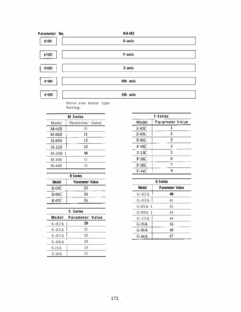
N A M EParameter
m
No.
X-axis
Y-axisB
Z-axis
I 4th axisIm
5th axismServo axis motor typeSetting:
M Series F Series
w
Model Parameter Value
M-03B 10
M-20B I 14
M-30B 15
M-44B 16
R Series
Model Parameter Value G Series
Model Parameter Value
G-02A I 40
G-03A I 41
G-05A I 42S Series G-09A I 43
M o d e l \ P a r a m e t e r V a l u e G-13A I 44S-02A \ 20
S-03A I 21
S-05A I 22
S-08A I 23
S-15A 24
S-30A 25
– 171 –

9.2 PARAMETER NUMBER TABLE (Cent’d)
Special Motor
Model I Parameter Value
S-07HS I 251
D-09HS11 \ 252
S-1OHS I 253
Parameter
m(Bit No.
D Series
Model Parameter Value
D-05E 50
D-1OE 51
D-15E 52
D-22E 53
D-37E 54
N A M E
7
I
[
[ II
I
6 5 4 3 2 1 0)
o :1 :
0 :1 :
0 :1 :
0 :
0 :
0 :
0 :
0 :
– 172 –

Parameter No. N A M Emmm
mEncoderSetting:
mm
I X-axis I
Y-axis
I Z-axis I
I 4th axis I
I 5th axis I
type
Type Parameter ValueLinear Scale o15-bit ABS 115-bit ABS (for Rotation Axis) 217-bit ABS 38,192 pulse new INC 1125,000 pulse new INC 1830,000 pulse new INC 19For C-Axis (360,000 Pulses) 23
X-axis 1I Y-axis I
I Z-axis I
mm
I 4th axis I
I 5th axis I
ExternaltypeSetting:
Type Parameter ValueLinear Scale o
encoder 15-bit ABS 115-bit ABS (for Rotation Axis) 217-bit ABS 38,192 pulse new INC 1125,000 pulse new INC 1830,000 pulse new INC 19For C-Axis (360,000 Pulses) 23
Spindle ISpindle encoder T y p etype
P a r a m e t e r V a l u e
Setting: 1024 Pulse INC (for Spindle) 21
– 1 7 3 –

PARAMETER NUMBER TABLE (Cent’d )
Parameter No.
mm
mmmmmmmm
N A M E
Ito
[
Set the axes disp]ay name by converting ASCII code to decimal notation.X-axis : #lioo iO #1102Y - a x i s : #llo3 to #llo5Z-axis : #1106 to #1108Set any of the following.4th axis : #1109 to #lIll5th axis : #1112 to #1114 }
Set as X : 8 8 0 0 0 0Set as Y : 890000Set as Z : 900000
Set any of the following.U:850(Jflfi---V: 860000W: 870000A: 650000B: 660000C: 670000
* Set servo axis automatic system axes name for#1149 to #1156.
I
II I
1 I
– 1 7 4 –

Parameter No. N A M Emmmm
wm
mmI #1159 I
I I
Set spindle display name by converting ASCII code to decimal notation.Set as follows : #1127 83
#1128 00#1129 00
*● ✍ Set spindle automatic system axes name for #1169 to
#1171.
I I
Set automatic system axes names in ASCII code.X-axis : #1142 to #1144 Set as X : 880000Y-axis : #1145 to #1147 Set as Y : 890000Z-axis : #1148 to #1150 Set as Z : 900000Set any of the followin~.4th axis : #1151 to #ll;35th axis : #1154 to #1156 } Set any of the following.
U: 850000V: 860000W: 870000A: 650000B: 660000C: 670000
name for #1100 to #lq* - Set servo axis indication 14.
– 1 7 5 –

9 . 2 PARAMETER NUMBER TABLE (Cent’d)
Parameter No. N A M Emm
I
mSet the automatic system spindle nameto decimal notation.
#1169 83#l17000#1171 00
by converting ASCII code
q*- Set spindle indication name for #1127 to #1129.
mmmmm
mmmI #1181 I
m
II I
I 1
I I
– 1 7 6 –

Parameter No. N A M E
m~
– 177 –

PARAMETER NUMBER TABLE (Cent’d)
Parameter
m
m
mmmmmmmmmmm
No. N A M E
INumber of control axes during high speed mode operation.Setting : 3 = 3 axes, 4 = 4 axes, 5 = 5 axesSetting range : 3 to 5
Additional 4th axis
Additional 5th axis
Input the address name of the axes addedduring high speed mode operation by convert-ing ASCII code to decimal notation.Set any one of the following.
U: 850000V: 860000W: 870000A: 650000B: 660000C: 670000
I I
1 I
I I
1 1
I 1
– 178 –

Parameter No, N A M E
mmm
w
I #1223 I
m
I #1 226 I
I #1229 I
m
I
I J
Spindle index confirmation timer.Setting : l = 4 m sSetting range : 1 to 225
I 1
Spindle indexing stop confirmation revolutions.Setting : 1=1 rpmSetting range : 1 to 255
1 1
Spindle indexing stop confirmation revolution at selection of spindle gearSetting :1 = 1 rpmSetting range :1 to 255
I I
B-axis.
– 1 7 9 –

9.2 PARAMETER NUMBER TABLE (Cent’d )
Parameter No. N A M E
mmmmmmmmm
mmn#1 244
mm
I
Spindle for solld tap.Setting range : 1
Servo axis for solld tap.Setting : 1 = X-axis
2 = Y-axis3 = Z-axis4 = 4th axis5 = 5th axis
Setting range “ 1 to 5
– 180 –

Parameter No. N A M E
mmmmmm
mmmmmI #1259 I
Solid tap return speed multiplying factor.Setting : 1 = 0.1 timeSetting range : 1 to 255
I I
I
Spindle loop control gear A.Setting range : 0 to 4
mSpindle loop control gear B.Setting range :0 to 4
\ #1263 I
– 181 –

9 . 2 PARAMETER NUMBER TABLE (Cent’d)
Parameter No. N A M E
m
I #1301 I
m
mmm
I I
– 1 8 2 –

Parameter
mmmmm
mI #1317 I
I #1318 I
mm
mmmm
I 1
I
1
To use the system, always set “1”.
To use the system, always set “1”.
I X-axis I
I Z-axis I
I 4th axis I
Error detect–ON area.Setting : 1 = Minimum detecting unitSetting range : 0 to 255
– 1 8 3 –

PARAMETER NUMBER TABLE (Cent’d )
Parameter No. N A M E
mm1 I
mmmm I
Error detect–ON area during spindle loop control.Setting : 1 = Minimum detecting unitSetting range : 0 to 255
mError detect-ON area during spindle loop control at spindle gear B selected.Setting : 1= Minimum detecting unitSetting range :0 to 255
m
mmm\ #1338
I
I
– 1 8 4 –

Parameter No. N A M E
mmB
mmmmmmB
mm
mI #1354 \
m
I
Multlplylng factor relatlve to spindle servo area rapid traverse rate.Setting : 1 = 1 %Setting range : 0 to 200
1
– 1 8 5 –

TABLE (Cent’d )9.2 PARAMETER
Parameter No.
mmm I Gear range 2 I Minimum spindle revolutions clamp,
Setting : 1 = 1 rpm/10 rpmSetting range : 0 to 30000
(Determined by #1002 DO)
mn#1404 I Gear range 1 I
Maximum spindle revolutions clamp.I J
Setting : 1 = 1 rpm/10 rpmSetting range : 0 to 30000
(Determined by #1002 DO)m [ Gear range 3 I
mm
[ Gear range 2 I MaximumSetting : 1
spindle motor revolutions.= 1 rpm/10 rpm by #1002 DO)
ions
m Setting range : 0 to 30000
range 1
I Gear range 3 I
mGear
Spindle motor I Gear range 2 Gear range 3II , Gear range 4
oDeration command I
1 Ov L.._._-l___._’_.__ .-.J ----------
o
r
Spindle revolut(rpm)
#1411- #1407
##1400
– 1 8 6 –

Parameter No. N A M E
m
I #1414 I
mm
I #1418 I
m
1 SOR
Spindle motor r/rein at spindle orientation (SOR) inputSetting : 1 = 1 r/reinSetting range : 0 to 32767
GRO 1Motor revolutions when spindle (GRO) is input.Setting : 1 = 10/32767 VSetting range : 0 to 32767
Spindle indexing origin position.Setting : 360/4096 degSetting range : 0 to 4096
Revolutions with 10V solid tap command.Setting : 1 = 1 rpm or 10 rpm (Determined by #1002 DO)Setting range : 0 to 32767
1Maximum revolutions of solid tap spindle.Setting : 1 = 1 rpm or 10 rpm (Determined by #1002 DO)Setting range : 0 to 32767
ISolid tap spindle position loop gain.Setting : 1 = 0.001 [S-’1Setting range : 0 to 32767
Revolutions in solid tap command 10V when spindle gear B is selected.Setting : 1=1 rpm or 10 rpm (depending on setting of #1002 DO)Setting range :0 to 32767
Maximum revolutions of solid tap spindle when spindle gear B is selected.Setting :1 = 1 rpm or 10 rpm (depending on setting of #1002 DO)Setting range :0 to 32767
– 1 8 7 –

9.2 PARAMETER NUMBER TABLE (Cent’d )
Parameter
B
mmI #1503 I
MmI #1506 II I
mm
No. N A M E
Spindle loop gain of solid tap when spindle gear B is selected.Setting : 1=0.01 [S -’lSetting range :0 to 32737
Solid tap servo shaft retraction in–position width.Setting : 1 = Minimum command unitSetting range : 0 to 32767
I Feedback side K1 I
Solid tap servo shaft synchronous correction parameter (Kl).Setting range : –32767 to 32767
Reference side K2
Solid tap servo shaft synchronous correction parameter (K2).Setting range : –32767 to 32767
I I
[ I
II I
I I
I 1
Number of teeth of gear A on the spindle side for spindle loopcontrol during solid tap.Setting : 1 = 1 toothSetting range : 0 to 32767
– 1 8 8 –

Parameter No. N A M E
mNumber of teeth of the spindle intermediate gear of gear A used forspindle loop control during solid tap.Setting : 1 = 1 toothSetting range : 0 to 32767
- Number of teeth on the motor side if there is no intermediate& gear.
Number of teeth of the intermediate gear of gear A used for spindleloop control during solid tap.Setting : 1 = 1 toothSetting range : 0 to 32767
- Will be O when there is no intermediate gear.
m
~Number of teeth on the motor side d gear A used for spindle loopcontrol during solid tap.Setting : 1 = 1 toothSetting range : 0 to 32767
@Will be O when there is no intermediate gear.
~Number of teeth of gear B on the spindle side for spindle loop controlduring solid tap.Setting,: 1=1 toothSetting range :0 to 32767
Number of teeth of the spindle intermediate gear of gear B used forspindle loop control during solid tap.Setting : 1=1 toothSetting range :0 to 32767
eNumber of teeth on the motor side if there is no intermediate gear.
~Number of teeth of the intermediate gear of gear B used for spindle loop.control during solid tap.Setting : 1=1 toothSetting range :0 to 32767
*a- Will be O when there is no intermediate gear.
– 1 8 9 –

PARAMETER NUMBER TABLE (Cent’d )
Parameter No. N A M E
m
I #1518 I
mmm
B
mmmmm
Number of teeth on the motor side of gear B used for spindle loop controlduring solid tap.Setting : 1=1 toothSetting range :0 to 32767
-Will be O when there is no intermediate gear.
~
Delay time when checking spindle speed attainment signal (SAGR).Setting : l=lmsSetting range : 0 to 32767
I I
1
I I
I
X ax[s 1Y-axis
– 1 9 0 –

Parameter No. N A M E
mm
mmI I
mmmI #1581 I
1 Z-axis
I 4th axis I
5th axis
Backlash offset amountSetting : 1 = 1 U mSetting range : 0 to 32767
L X-axis position loop gain (KP)
Setting : 1 = 0.01 (1/s)Setting range : 1 to 20000
IX-axis speed loop gain (K,)
Setting : 1 = 0.1 (1/s)Setting range : 1 to 32767
X-axis speed loop integral time constant (Ti )
mSetting : 1 = 0.1 msSetting range : 1 to 32767
m
X-axis speed FF gain (K.~f~)
Setting : 1 = l%Setting range : 1 to 100
I
– 191 –

9.2 PARAMETER NUMBER TABLE (Cent’d)
Parameter
m
mmm
m
No. N A M E
X-axis axial torsion filter time constant (T. )
Setting : 1 = 0.01 msSetting range : 1 to 32767
Scale factor for X-axis monitor board signal selection
Setting : See the following table.Setting range : 1 to 32767
Table CH1 (D/Al) and CH2 (D/A2) Output Signal Select ionand Output Scale Factor
Value of #1589 0111213 1024 ] 1025 \ 1026 \ 1027Signal
CH1 Output NameTorque instruction Motor r/rein.
(D/Al ) Scale ~ z ~ 8 ~ 2 ~ 8FactorSignal
CH2 Output Name Speed instruction
(D/A2) Scale ~ 2 ~ 8 ~ 2 ~ 8Factor
I Y-axis position loop gain (KP)
setting : 1 = 0.01 (1/S)
Setting range : 1 to 20000
Y-axis speed loop gain (K, ) I
m
Setting : 1 = 0.1 (1/s)Setting range : 1 to 32767
I Y-axis speed looP integral time constant (~i ) I
Setting : 1 = 0.01 msSetting range : 1 to 32767
– 192 –

Parameter No. N A M E
m
mmm
Y-axis speed FF gain (K.~~/)
Setting: 1= l%Setting range : 1 to 100
I I
1 (Y-axis axial torsion filter time constant (Tfi)
Setting : 1 = 0.01 msSetting range : 1 to 32767
1 I
Scale factor for Y-axis monitor board signal selection
Setting : See the following table.Setting range : 1 to 32767
Table CH1 (D/Al ) and CH2 (D/A2) Output Signal Select ionand Output Scale Factor
Value of. #1599 0111213 1024 I 1025 I 1026 I 1027Signal
CH1 Output Name Torque instruction Motor r/rein.
(D/Al ) Scale ~ z 4 ~ ~ 2 4 8Factor I-..Signal
CH2 Output NameSpeed instruction
(D/A2) Scale ~ z 4 g ~ 2 4 8Factor
Z-axis position loop gain (Kp)
Setting : 1 = 0.01 (1/S)
Setting range : 1 to 20000
Z-axis speed looP gain (K”)
Setting : 1 = 0.1 (1/s)Setting range : 1 to 32767
Z-axis speed loop integral time constant (Ti )
Setting : 1 = 0.01 msSetting range : 1 to 32767
– 1 9 3 –

9.2 PARAMETER NUMBER TABLE (Cent’d )
Parameter No. N A M E
I #1603 I
m
m
m
Z-axis speed FF gain (K, fff)
Setting : 1 = lxSetting range : 1 to 100
Z-axis axial torsion filter time constant (T. )
Setting : 1 = 0.01 msSetting range : 1 to 32767
Scale factor for Z-axis monitor board signal selection
Setting : See the following table.Setting range : 1 to 32767
Table CH1 (DIA1) and CH2 (D/A2) Output Signal Select ionand Output Scale Factor
Value of #1609 0111213 1024 I 1025 \ 1026 ] 1027Signal
CH1 Output Name Torque instruction Motor r/rein.
(D/Al ) Scale ~ z 4 ~ ~ 2 4 8FactorSignal
CH2 Output NameSpeed instruction
(D/A2) Scale ~ 2 4 g ~ 2 4 8Factor
– 1 9 4 –

Parameter No. N A M E
ml 4th axis position looP 9ain (Kj)
Setting : 1 = 0.01 (1/s)Setting range : 1 to 20000
ml 4th axis speed looP gain (K,)
Setting : 1 = 0.1 (1/s)Setting range : 1 to 32767
ml 4th axis speed loop. integral time constant (T, )
Setting : 1 = 0.01 msSetting range : 1 to 32767
ml 4th axis speed FF gain (K, fff)
Setting : 1 = l%Setting range : 1 to 100
ml 4th axis axial torsion filter time oonstant (T. )
Setting : 1 = 0.01 msSetting range : 1 to 32767
– 1 9 5 –

9.2 PARAMETER NUMBER TABLE (Cent’d)
Parameter No. N A M Em
m
m
m
mmmm
Scale factor for 4th axis monitor board signal selection
Setting : See the following table.Setting range : 1 to 32767
Table CH1 (D/Al ) and CH2 (D/A2) Output Signal Select ionand Output Scale Factor
Value of #1619 01112]3 1024 ] 1025 I 102611027Signal
CHI Output Name Torque instruction Motor r/rein.
(D/Al ) Scale ~ z 4 ~ ~ 2 4 ~FactorSignal
CH2 Output NameSpeed instruction
(D/A2) Scale ~ z 4 ~ ~ 2 4 gFactor
I 5th axis position looP gain (Kj)
Setting : 1 = 0.01 (1/s)Setting range : 1 to 20000
5th axis speed looP gain (K,)
Setting : 1 = 0.1 (1/s)Setting range : 1 to 32767
5th axis speed looP integral time constant (Ti)
Setting : 1 = 0.01 msSetting range : 1 to 32767
[
5th axis speed FF gain (K, fff)
Setting : 1 = lxSetting range : 1 to 100
5th axis axial torsion filter time constant (T. )I
Setting : 1 = 0.01 ms
Setting range : 1 to 32767
– 1 9 6 –

Parameter No. N A M E
I #1628 I
m
n#1671
m
mm
I Scale factor for 5th axis monitor board signal selection I
Setting : See the following table.Setting range : 1 to 32767
Table CH1 (D/Al) and CH2 (D/A2) Output Signal Selectionand Output Scale Factor
Value of #1629 Oll]2\3 1024 I 1025 ] 1026 ] 1027Signal
CH1 Output Name Torque instruction Motor r/rein.
(D/Al ) Scale ~ ~ a ~ ~ z a ~FactorSignal
CH2 output Name Speed instruction
(D/A2) Scale ~ z a ~ ~ z a ~Factor
I Y–axis I
Torque limit value (+)Setting : 1 = 1%Setting range : 1 to 32767
– 1 9 7 –

PARAMETER NUMBER TABLE (Cent’d)
Parameter No. N A M E
mmB
mmmm
\ X-axis I
I Y-axis I
I 4thaxis I
I 5thaxis I
I #1701 I
mmm
Torque limit value (-)Setting : 1 = 1%Setting range : –32767 to –1
I Z-axis I
\ 4th axis I
Backlash offsetSetting : 1 = 1 pulse (Minimum detecting unit)Setting range : 1 to 32767
-b - Minimum detection unit = L/PGo Where,
L = Displacement per rotation of F motor(determined by #1821 and after)
PG = Number of pulses per rotation of PG(determined by #1071 and after)
– 1 9 8 –

Parameter
mNo. N A M E
mmmm
mmmmm
m
I X-axis I
I Z-axis I
I 5th axis I
time constant1 = 0.01 m s
Setting range : 1 to 32767
BacklashSetting :
m
– 1 9 9 –

PARAMETER NUMBER TABLE (Cent’d )
Parameter No. N A M E
mmmmmmmm
M
n#1805
mmmmI #1810 I
X-axis form compensation coefficient 1
Y-axis form compensation coefficient
Z-axis form compensation coefficient
4th axis form compensation coefficient
5th axis form compensation coefficient
Form compensation coefficient.Setting : 1=0.001 timeSetting range : 0 to 32767Correction constant of followup error relative to servo axiscommand.
I I
– 2 0 0 –

Parameter
mI #1812 I
wmI #1815 I
m
m
m
m
I
I X-axis I
I Y-axis I
I 4th axis I
I #1825 I I 5th axis I
mmm
Amount of movement per motor revolution.Setting : 1 = Minimum detecting unit or 0.001 degSetting range : 0 to 999999999
– 201 –

9.2 PARAMETER NUMBER TABLE (Cent’d)
Parameter No. N A M E
I #1829 I
mmmmmm
mmmmmmI #1843 I
1
I Y-axis I
I Z-axis ILoad inertia (GD2/4)Setting : 1 = 0.01 kg-cm’Setting range : 0 to 32767
I 1
I X-axis I
I Y-axis I
I Z-axis I
4th axis I
– 2 0 2 –

Parameter No. N A M E
m
mm
mmmH
mmmB
[5th axis
Linear scale minimum detection unit (for linear scale typeexternal PG )Setting : 1 = 0.001 u m (0.000001 deg)Setting range : 0 to 999999999Number of pulses generated by external PG per motor rotation(for rotary encoder type external PG)Setting : 1 = 1 pulseSetting range : 0 to 999999999
I
I
– 2 0 3 –

9.2 PARAMETER NUMBER TABLE (Cent’d)
Parameter No. N A M E
ELROTJOG ZRNRPD FOVAB PRDOV SCRDRN RPDDRN
(Bit No. 7 6 5 4 3 2 1 0)
m“1 :
m’:1 :
m“1 :
Jog speed of rotating shaft is not made 1/10 of linearaxis.
Jog speed of rotating shaft is made 1/10 of linear axis.
Uses rapid feed until completion of reference pointreturn after powr is switched on.
Uses jog until completion of reference point return afterpower is switched on.
Feed override signal is valid at “ 1” (NC contact).Feed override signal is valid at “O” (NC contact).
Sets rapid feed override to the 4 steps of FO, 25, 50 and100% .
Sets rapid feed override to the 6 steps of FO, Fl, F2, 25,50, 100%.
Dry run is valid during tapping.Dry run is invalid during tapping.
Makes dry run invalid in rapid feed command.Makes dry run valid in rapid feed command.
– 2 0 4 –

Parameter No. N A M E
m(Bit No.
Parameter
m(Bit No.
SKPFEO
7 6 5 4 3 2 1 0)
O : Feeding speed complies with F code when a skip= function.
1: Sets feeding speed to parameter speed when a skipfunction.
No. N A M E
HOFS5 HOFS4 HOFS3 HOFS2 HOFS1
7 6 5 4 3 2 1 0)
Invalidates 5th axis Auto mode handle offset.Validates 5th axis Auto mode handle offset.
Invalidates 4th axis Auto mode handle offset.Validates 4th axis Auto mode handle offset.
Invalidates Z-axis Auto mode handle offset.Validates Z-axis Auto mode handle offset.
Invalidates Y-axis Auto mode handle offset.Validates Y-axis Auto mode handle offset.
Invalidates X-axis Auto mode handle offset.Validates X-axis Auto mode handle offset.
– 2 0 5 –

9.2 PARAMETER NUMBER TABLE (Cent’d)
Parameter No. N A M E
m I’P””’l HOFSMV1
(Bit No. 7 6 5 4 3 2 1 o )
=0:1 :
0;;
Parameter No.
Sets multiplying factor to 100 when selecting handlemultiplying factor of 100.
Uses multiplying factor set by the parameter whenselecting a handle multiplying factor of 100 (#2459).
Enables Auto mode handle offset other than whenexecuting a rapid feed command.
Enables Auto mode handle offset only duringinterpolation.
N A M E
ml FFEED
(Bit No. 6 5 4 3 2 1 0)
no :
0 :01,
0 :01:
0 :01..
0 :01:
0 :0 1 ” :
0 :01,
mlO: Feedrate will be F5 at mm/min when 0.001m input
and F4. 1 at inch/rein when 0.0001 in input.1: Feedrate will be F5. 1 at mm/min when 0.001m input
and F4. 2 at inch/rein when 0.0001 in input.
– 206 –
Parameter No. N A M E
(Bit No. 7 6 5 4 3 2 1 o )
– 2 0 7 –

9.2 PARAMETER NUMBER TABLE (Cent’d)
Parameter No. N A M Em
mm
m
mm
II I
I I
I
I
– 2 0 8 –

Parameter No.
m
mmmm
] F1 at l-digit specification \
I F2 at l-digit specification \
] F3 at l-digit specification ]
] F4 at l-digit specification ]
[ F5 at l-digit specification I
I II F6 at l-digit specification I
F7 at l-digit specification
I F8 at l-digit specification
F9 at l-digit specification
A M E
Change in traverse speedwhen the manual pulsegenerator is turned onegraduation under l-digitspecification.Setting : 1 = 0.1 mm/
rein/pulseSetting range : 0 to 255
– 2 0 9 –

9.2 PARAMETER NUMBER TABLE (Cent’d)
Parameter No. N A M EmFI
I Jog feedrate of switch position O I
Jog feedrate of switch position 1
m I Jog feedrate of switch position 2 I
Jog feed rate of switch position 3mm Jog feed rate of switch position 4
I 1
I Jog feedrate of switch position 5 I
I Jog feedrate of switch position 6 I
m I Jog feedrate of switch position 7
m I Jog feedrate of switch position 8 I
m Jog feedrate of switch position 91
Jog feedrate of switch position 10mm Jog faedrate of switch position 11
m [Jog feedrate of switch position 12
1Jog feedrate of switch position 13mJog feedrate of switch position 14
Imm Jog feedrate of switch position 15
Jog feed rate of switch position 16
Jog feedrate of switch position 17
– 2 1 0 –

Parameter
m
No. N A M E
Jog feedrate of switch position 18
I #2419 I Jog feed rate of switch position 19
I Jog feedrate of switch position 20 I
Jog feed rate of switch position 21
H
I Jog feedrate of switch position 22 I
Jog feed rate of switch position 23
I #2424 I
Hmmm
Jog feedrate of switch position 24
Jog feedrate of switch position 25
Jog feedrate of switch position 26
Jog feedrate of switch position 27
Jog feedrate of switch position 28
Jog feedrate of switch position 29
Jog feedrate of switch position 30
Jog feedrate of switch position 31
Feedrate corresponding to the jog feedrate selection switch position.Setting : 1 = 1 mm/min, 1 = 0.1 in. /rein, or 1 = 1 deg/minSetting range : 0 to 32767
– 2 1 1 –

9.2 PARAMETER NUMBER TABLE (Cent’d)
Setting example
Parameter Manual continuous feedrate (mm/min)Switch #2432 = O #2432 = O #2432 = 10 #2432 = 10position No. Set value #2433 = O #2433 = O #2433 = 25 #2433 = 25
#2434 = O #2434 = 10 #2434 = O #2434 = 10
0 #2400 o 0 0 0 01 #2401 1 1 0.1 1 0.12 #2402 2 2 0.2 2 0.2
3 #2403 4 4 0.4 4 0.4
4 #2404 6 6 0.6 6 0.6
5 #2405 8 8 0.8 8 0.8
6 #2406 10 10 1.0 10 1.0
7 #2407 12 12 1.2 12 1.2
8 #2408 15 15 1.5 15 1.5
9 #2409 20 20 2.0 20 2.010 #2410 25 25 25 25 25—.—11 #2411 30 30 30 30 30
12 #2412 40 40 40 40 40——13 #2413 50 50 50 50 50—14 #2414 60 60 60 60 60
15 #2415 80 80 80 80 80
16 #2416 100 100 100 100 100
17 #2417 120 120 120 120 120
18 #2418 150 150 150 150 150
19 #2419 200 200 200 200 200
20 #2420 250 250 250 250 250
21 #2421 300 300 300 300 300
22 #2422 400 400 400 400 400
23 #2423 500 500 500 500 500
24 #2424 600 600 600 600 600
25 #2425 800 800 800 8000 8000
26 #2426 1000 1000 1000 10000 10000
27 #2427 1200 1200 1200 12000 12000
28 #2428 1500 1500 1500 15000 15000
29 #2429 2000 2000 2000 20000 20000
30 #2430 2500 2500 2500 25000 25000
31 #2431 3000 3000 3000 30000 30000
Standard Special settingsetting
– 2 1 2 –

Parameter No. N A M E
m~Sets numerical value of jog feedrate parameter to x lo and x 100.Setting : 1 = 1 multiplyingSetting range : 1, 10, 100
m~Specifies switch position from which to multiply under #2432 + O.Setting range : 0 to 31
Position specification to multiply the jog feedrate parameternumerical value b y 1/10.If #2433 and #2434 are set simultaneously, #2434 has a priority.Setting range : 0 to 31
1
Speed during execution of skip.Setting : I = 1 mm/min, 1 = 0.1 in. /rein, or 1 = 0.001 deg/minSetting range : 0 to 32767
I I r I
I 1 1 1I #2443 I I II I I I
r I
Speed in relation to rapid traverse external deceleration.Setting : 1 = 1 mm/min, 1 = 0.1 in. /rein, or 1 = 0,001 deg/minSetting range : 0 to 32767
Speed in relation to external deceleration of feedrate.Setting : 1 = 1 mm/min, 1 = 0.1 in. /rein, or 1 = 0.001 deg/minSetting range : 0 to 32767
– 213 –

9.2 PARAMETER NUMBER TABLE (Cent’d )
Parameter No. N A M E
mm
m
H
I #2453 I
m
m
I FO speedJ
Rapid traverse rate overrideAt #2000 D3 = OSetting : 1= lmm/min, 1=0.1 in/rein or 1= deg/minSetting range :0 to 32767At #2000 D3 = 1Setting : 1= lxSetting range :0 to 100
_ S e t t i n g
1
Rapid traverse rate override.: 1 = 1 mm/min, 1 = 0.1 in. /rein, or
m ‘e’’in’r:~o”y::;:;:in
I I
I
I
Multiplying factor of 100 times handle feed.Setting : 1 = X 1Setting range : 0 to 32767
– 214 –

Parameter No, N A M E
I #2460 I
mI #2462 I
I 5th axis I
(v)
SPEED
Rapid feeddetermined#2801 to #28~5
rateby —
.
Accel/decel speed constant for 1st stage rapid feed.S e t t i n g : l = l m s Multiplesof4Setting range: 4t032767
. . . ----- .
Rapid feed accel/decel speedconstant determined by #2461 to #2465
TIME (t)
– 2 1 5 –

9.2 PARAMETER NUMBER TABLE (Cent’d)
Parameter No. N A M E
B
B
n#2479
B
B
B
B
Spindle
Spindle accel/decel speed time constant.Setting : 1 = 1 ms Multiples of 4Setting range : 4 to 32767
Spindle accel/decel speed time coustant when spindle gear B is selected.Setting : 1= lms Multiples of 4Setting range :4 to 32767
I I
I
1
I I
– 216 –

Parameter No. N A M E
– 2 1 7 –

9.2 PARAMETER NUMBER TABLE (Cent’d )
Parameter
m
mmm
No.
I Y-axis I
/ 4th axis I
m
N A M E
i
Accel/decel speed constant for normal cutting.Setting : I=lmsSetting range : 0 to 32767
JTANGENT
\A
#2800 “
r’ T
{#25ol to #25C15 During normal cutting
#2511 to #2515 When tapping screw
#2821 to #2825 Normal cutting accel/decel speed bias#2831 to #2835 Accel/decel speed bias when tapping screw
– 2 1 8 –

Parameter No. N A M E
n#251 1
I #2512 I
mn#2514
k
I Z-axis IAccel/decel speed timethread and tapping.Setting : 1 = 1 ms
constant
Setting range : 0 to 32767
when cutting
– 219 –

PARAMETER NUMBER TABLE (Cent’d )
Parameter No. N A M E
I X-axis I
I Y-axis I
I 4th axis \I Reference point return approach speed.
Setting : 1 = 1 mm/min, 1 = 0.1 in. /rein, or1 = 0.001 deg/min
Setting range : 0 to 32767
Rapid feed
v(#2801 to#2805) Approach speed
#2521 t0#2525)
(#2531 t0#2535)
Travel distance#4451 to#4455)
Speed sequence
Deceleration LS
-------Origin point signal
II1III11
signal
. Reference point return direction: #4002 DOtoD4Reference point return valid/invalid:#4022 DOt0D5
– 2 2 0 –

Parameter No N A M E
m
mI X-axis I
I Z-axis I
m
m
B
I 5th axis I
Reference point return creep speed.Setting : 1 = 1 mm/min, 1 = 0.1 in. /rein, or
1 = 1 deg/min.Setting range : 0 to 32767
I 1
Spindle index starting speed.Setting : 1 = 1 rpmSetting range : 1 to 32767
Spindle index starting speed when spindle gear B is selected.Setting : 1=1 rpmSetting range :1 to 32767
Spindle index creeping speed.Setting : 1 = 1 rpmSetting range : 1 to 32767
I #2547 I
Spindle index creeping speed when spindle gear B is selected.Setting : 1=1 rpmSetting range :1 to 32767
– 221 –

9.2 PARAMETER NUMBER TABLE (Cent’d)
Parameter No. N A M E
m
mm
mB
mm
I
I
Handle accel/decel speed constant.Setting : 1 = 1 ms Multiples of 4Setting range : 4 to 32767
– 2 2 2 –

Parameter No. N A M E
I 1 I II
I I L I
I 1 I f
I I I I
Cutting feed accelerationSetting : 1 = 0.001 m/s2 Multiples of 4Setting range :125 to 32767
mlX-axis
Cutting feed accel/decel S-curve degreeSetting range : 1 to 6
I 1 I I
– 2 2 3 –

9.2 PARAMETER NUMBER TABLE (Cent’d)
Parameter
m
I #2592 I
m I Z-axis I
I #2594 I I 4th axis I
I 5th axis I
Rapid traverse accel/decel S-curve degreeSetting range : () to 20
m
mI #2803 I
Cutting feed maximum speed. (Linear axis)Setting : 1 = 1 mm/min or 1 =0.1 in./minSetting range
~
I 4thaxis I
Rapid traverse rate.Setting : 1 = 1 mm/min, 1 = 0.1 in. /rein
1 = 1 deg/minSetting range : 0 to 240000
or
I 5th axis I
– 2 2 4 –

Parameter
m
I #281 1 I
B
m
B
F
No. N A M E
Maximum cutting feed speed (rotation axis)Setting : 1 = 1 deg/min.Setting range : 0 to 240000
I
1
I Z-axis I
I 4th axis I
I 5th axis I
Cutting feed accel/decel speed bias.Setting : 1 = 1 mm/min, 1 = 0.1 in. /rein, or
1 = 1 deg/minSetting range : 0 to 240000
– 2 2 5 –

9.2 PARAMETER NUMBER TABLE (Cent’d)
Parameter No. N A M E
I #2830 I
mu
I #2833 I \ Z-axis I
I 4th axis II I
I #2862 I
B
Accel/decel speed bias when tapping.Setting : 1 = 1 mm/min, 1 = 0.1 in. /rein, or.
1 = 1 deg/minSetting range :0 to 240000
Maximum feed speed of handle linear axis.Setting : 1 = 1 mm/min or 1 = 0.1 in./minSetting range : 0 to 240000
Maximum feeding speed of handle rotating axis.setting : 1 = 1 deg/minSetting range : 0 to 240000
Speed in circle cutting high speed section.Setting : 1 = 1 mm/min or 1 = 0.1 in. /reinSetting range : 0 to 240000
Lag pulses cramping value for handle.Setting : 1 = 1 pulseSetting range : 0 to 240000
* Clamping process is not executed when “O” is set.
IShift speed of canned cycle G76 and G77.Setting : 1 = 1 mm/min or 1 = 0.1 in. /reinSetting range : 0 to 240000
– 2 2 6 –

Parameter No. N A M Em~Maximum feedrate of F1 digit (F1–F4) command.Setting : 1 = 1 mm/min, 1 = 0.1 in. /mm, or 1 = 1 deg/minSetting range : 0 to 240000
Maximum feedrate of F1 digit (F5–F9) command.Setting : 1 = 1 mm/min, 1 = 0.1 in. /mm, or 1 = 1 deg/minSetting range : 0 to 240000
) 1 , 1
1 1 I 1
I I 1 I
I 1 I 1
, 1 ,
I1 I I I
I
I I I I
IL I I I
, I
II I I I
– 2 2 7 –

9.2 PARAMETER NUMBER TABLE (Cent’d)
Parameter No. N A M E
ml POSCHG3 POSCHG2 POSCHG1 ZOFSNEG
(Bit No. 7 6 5 4 3 2 1 o )
1:
m“’
Workpiece coordinate system is used to display positionson program check screen.
Mechanical coordinate system is used to displaypositions on program check screen.
Workpiece coordinate system is used to display positionson offset screen.
Mechanical coordinate system is used to displaypositions on offset screen.
Mechanical coordinate system is used to displaypositions on workpiece shift screen and displacementscreen.
Workpiece coordinate system is used to display positionson workpiece shift screen and displacement screen.
Offset value is added at Z-axis current position display.Offset value is not added at Z-axis current positiondisplay.
– 2 2 8 –

Parameter No. N A M E
mlSTPDSPW TPDSPW MPTDSP TM06 SETUP ETMDSp
(Bit No. 7 6 5 4 3 2 1 o )
m O : Subtool word display is ineffective.1 : Subtool word display is effective.
m O : Word display of tool pot invalid.1: Word display of tool pot valid.
=O : Intermediate pot display on ATC screen is ineffective.1 : Intermediate pot display on ATC screen is effective.
m O : If T command and M06 command are in the sameblock, T command takes precedence.
1: If T command and M06 command are in the sameblock, M06 command takes precedence.
O : Setup menu screen is effective.0.SET U P 1 . Setup menu screen is ineffective.
O : External timer display invalid.0 .‘TM ‘Sp 1. External timer display valid.
Parameter No. N A M E
=1 SRCH2 SRCH 1 ABSINC2 ABSINC1 INPSEL MDISTRT MDIRST MDIKEP
(Bit No. 7 6 5 4 3 2 1 o )
BO : Operation process address search is made by binary.1: Operation process address search is made by character.
m O : Editing process address search is made by binary.1: Editing process address search is made by character.
O : Offset display input is fixed to absolute input.0 .ABSINC2 1 . offset display input is f ixecl to incremental inPUt.
O : Work shift display input is fixed to absolute input.0 .ABSINC1 1 . Work shift display input is fixed to incremental input.
m O : Work shiftloffset display is switched by soft keys.I : Work shift/offset display is switched bY #3000(D4 “Ds)”
O : MDI operation starts from current cursor position.0 .MD lSTR~ 1 . MDI operation starts from beginning of MDI program.
O : Panel reset and external reset clears MDI buffer.MDIRST 1 : panel reset or external reset does n~t clear MDI buffer.
m O : If M02 or M30 is specified, MDI buffer is cleared whenMDI operation is completed.
1: If M02 or M30 is specified, MDI buffer is not clearedwhen MDI operation is completed.
– 2 2 9 –

9.2 PARAMETER NUMBER TABLE (Cent’d)
Parameter No. N A M E
mlATCOSP RUNSEL EDPWOF INTDSP3 INTDSP2 DSPSEL1 DSPSELO
(Bit No. 7 6 5 4 3 2 1 0)
0;A T C D S P :
m“:1 :
m “ ’1:
m
ATC display setting is made by byte +byte.ATC display setting is made by word.
Does not display spindle tool and next tool in operationprocess program display.
Displays spindle tool and next tool in operation processprogram display.
Can reset an alarm confirmation requested program.Resets an alarm confirmation requested program aftertroubleshooting.
Input setting at power ON is to be absolute input.Input setting at power ON is to be incremental input.
Preparation process display at power ON is to be workcoordinate system job.Preparation process display at power ON is to be tool job.
——————_ D1 DOo 0 4-position screen
Power-onInitial Screen
o 1 Program check screen
Selection 1 0 Editing screen1 1 4-position screen
– 2 3 0 –

Parameter No. N A M E
ml EDTLOCK2 Unusable U M09000
(Bit No. 7 6 5 4 3 2 1 o )
=0’1 :
Enables work coordinate system, work shift value or offsetto be changed.
Disables work coordinate system, work shift value or offsetto be changed.
Used by the system. Must be set to O.
Edit, display and punchoutnumbers 09000 to 09999.Edit, display and punchout09000 to 09999.
possible of program
inhibit of program numbers
– 231 –

9.2 PARAMETER NUMBER TABLE (Cent’d )
Parameter No. N A M E
01#3005 ONOALT CLNO ONOCHG M02M99 PRGNO PONON MERSIN
(Bit .No. 7 6 5 4 3 2 1 o )
m“1 :
m“1 :
B’:1:
m’:1 :
m“1 :
m“1:
Does not change registered O-number when O-number in the program is changed in editing display.Changes registered O-number when O-number in theprogram is changed in editing display.
Code “:” of 1S0 codes not converted to “O” during tapeinput.
Code “:” of 1S0 codes converted to “O” during tapeinput.
No automatic edit for O number when program’ rename,copy and store are executed.
Edits automatically for O number when programrename, copy and store are executed.
Does not consider completed M code (M02,M30,M*99)as program end when loading tape.
Considers completed M code (M02,M03,M*99) asprogram end when loading tape.
Considers program No. as a numerical value followingo.
Cqnsiders program No. as the numerical valuefollowing O or N.
Clears program number after power is switched on.Does not clear program number after power isswitched on.
Warning issued if there is already a O when loading atape.
Erases program and writes if there is already a O whenloading a tape.
q*- l.If NC data peculiar control is not provided at 1/0 verifica-
tion, #3005 DO and D2 to D5 are all treated as “O”disregarding parameter values.
2.NC data peculiar control parameter (l: Provided, O: Not pro-vided)1st port input #0012 D7 1st part output #0014 D72nd port input #0017 D7 2nd port output #0019 D7
– 2 3 2 –

Parameter No. N A M E
mlCOMPRT3 COMPRT2 COMPRT1 CARA DNCBUF2 DNCBUF1 COMERR NCDEV
(Bit No. 7 6 5 4 3 2
B7 D6 D5Communi- ,0 0 0 protocol 1cation o 0 1 Protocol 2Module o 1 0 Protocol 3Protocol o 1 1 Protocol 4
m O : Control character not sent1 : Control character sent
mytes 1
1 o )
Parameter No.
NC alarm occurs at communication module error.NC alarm does not occur at communication moduleerror.
Tape operation device is selected by input from 1/0 port.Tape operation device is selected by setting.
N A M E
01#3007 COMBUF COMERR
(Bit No. 7 6 5 4 3 2 1 0)
0:COMERR :
Communication module does not buffer 150 bytes ofDAT binary data after WAT command.
Communication module buffers 150 bytes of DATbinary data after WAT command.
As usual.Only TIME OUT ERROR is not output at #3006 D1 = 1.
– 2 3 3 –

9.2 PARAMETER NUMBER TABLE (Cent’d)
Parameter No. N A M E
ml Unusable Unusable
6
0:1 :
0 :1 :
0 :1 :
0:1 :
0 :1 :
0 :1 :
0 :1 :
0 :1 :
5
For system use.Always set O.
For system use.Always set O.
4 3 2 1 0)
Parameter No. N A M E
m~
DNC high-speed cutting data start character specificationSetting : ASCII code character can be set for each
parameter #3106, #3107, and #3108.
– 2 3 4 –

Parameter
m
m
mI #3409 I
No. N A M E
First title display line when power is switched on.Setting : Convert ASCII code to decimal from first character and
set.Setting example : YASKAWA : Y#3400 = 89 YASNAC : Y#3410
A#3401 = 65 A#3411S #3402 = 85 S #3412K#3403 = 75 N#3413A#3404 = 65 A#3414W#3405 = 87 c#3415
= 89= 65= 85= 78= 65= 67
A#3406 = 65 #3416 = 00#3407 = 00 #3418 = 00#3408 = 00 #3419 = 00#3409 = 00
T YASKAWA >
YASNAC
\ JCRT DISPLAY
– 2 3 5 –

9.2 PARAMETER NUMBER TABLE (Cent’d )
Parameter No. N A M E
mmmmm
m
m
1Set second line of title display by the same procedure as in #3400 to#3409 when switching on power.
Place the multiplying factor of the first line in the first digit(Range 1 to 3).Place the multiplying factor of the 2nd line in the second digit(Range 1 to 3).Uses hexadecimal for the 2 digit value and sets this value afterconverting to decimal value.(Setting example) Set 12 H = 18 when the first line is x 2 and thesecond line is x 1.
– 2 3 6 –

Parameter No. N A M E
m~Title display.Place the first line starting position in the 1st and 2nd digits(Range 1 to 39).Place the second line starting position in the 3rd and 4th digits(Range 1 to 39).Uses hexadecimal for the 2 digit value and sets this value afterconverting to decimal value.(Setting example) Setting example of 10th character on the firstline and the 12th character on the second line.Set OCOAH = 3082
m~Tool pot display start No.Setting : Keep memory numberSetting range : 7000 to 7999
m~Tool pot display end No.Setting : Keep memory numberSetting range : 7000 to 7999
m~ATC display magazine tool numberSetting : Keep memory numberSetting range : 7000 to 7999
m~ATC display spindle tool numberSetting : Keep memory numberSetting range : 7000 to 7999
m~ATC display weight pot tool numberSetting : Keep memory numberSetting range : 7000 to 7999
Subtool pot display start numberSetting : Keep memory numberSetting range : 7000 to 7999
– 2 3 7 –

9.2 PARAMETER NUMBER TABLE (Cent’d)
Parameter No. N A M E
a#3428
m
ISubtool pot display end numberSetting : Keep memory numberSetting range : 7000 to 7999
1
Communication module RDI command PLC keep memorynumberSetting : Keep memory numberSetting range : 7000 to 7999
ICommunication module SDO command PLC keep memorynumberSetting : Keep memory numberSetting range : 7000 to 7999
– 2 3 8 –

Parameter No. N A M E
m
B
B
F
m
Spindle forward run M-code No. for drawingSetting range :0 to 999
Spindle reverse run M-code No. for drawingSetting range :0 to 999
ISpindle stop M – code No. for drawingSetting range :0 to 999
Spindle constant position stop M – code No. for drawingSetting range :0 to 999
Tool replacement M – code No. for drawingSetting range :0 to 999
Constant ON M – code No. for drawingSetting range :0 to 999
Constant OFF M – code No. for drawingSetting range :0 to 999
Average time required for M – code command for drawingSetting :1 = lmsSetting range :0 to 65535
[Average time required for S – code command for drawingSetting :1 = lmsSetting range :0 to 65535
Average time required for T– code command for drawingSetting :1 = lmsSetting range :0 to 65535
– 2 3 9 –

9.2 PARAMETER NUMBER TABLE (Cent’d)
Parameter No. N A M E
mm
r II #3827 I
mI #3829 I
m
m
0
0
Always set O to use the system.
oI J
I
I o IAlways set O to use the system.
Io
– 2 4 0 –

Parameter No. N A M E
mmmmm
m
mm
I #3846 I
B
I #3848 I
m
Io
Always set O to use the system.
o
0
Always set O to use the system.
o
0
Always set O to use the system.
o
0
Always set O to use the system.
Io
0
Always set O to use the system.
o
0Always set O to use the system.
o
0
Always set O to use the system.
o
0
Always set O to use the system.
– 241 –

9.2 PARAMETER NUMBER
Parameter No.
mmm
m
TABLE (Cent’d)
N A M E
o I
I o IAlways set O to use the system.
I o I
I o IAlways set O to use the system.
I I
I
– 2 4 2 –

Parameter No. N A M E
ml RSTG03 RSTG02 POG08B POG08A PONG04 PONG03 RSTGO1
(Bit No. 7 6 5 4 3 2 1 o )
m“’1 :
m“’1 :
Sets the G code of the 03 group in accordance with #4000D1 when resetting.
Sets the G code of the 03 group as the G code of thecommand immed iately prior when resetting.
Sets the G code of the 02 group as G17 when resetting.Sets the G code of the 02 group as the G code of thecommand immediately prior when resetting.
\ D41D31
}
G code of the 08 group
=
O 0 G49O 1 G43when power is switched on.1 0 G44
Sets G code of 04 group as G98 when power is switched on.Sets G code of 04 group as G99 when power ii switched on.
Sets G code of 03 group as G90 when power is switched on.Sets G code of 03 group as G91 when power is switched on.
Sets G code of 01 group as GOO when power is switched onand when reetting.
Sets G code of 01 group as GO1 when power is switched onand when resetting.
– 2 4 3 –

9.2 PARAMETER NUMBER TABLE (Cent’d)
Parameter No. N A M E
mlEOTSTLK ZRNILK ZRNG54 PONG54 MIRG28 PONM97 PONM95
(Bit No. 7 6 5 4 3 2 1 o )
m O : Displays alarm when execution of program is startedafter editing without resetting.
1 : No alarm when execution of program is started afterediting without resetting.
m O : Whether an alarm (0411 to 0415) occurs depends on #4018 DOto D4 when cycle is started without conducting all axesreference point return after turning on power.
1: Alarm not displayed when cycle is started without conductingall axes reference point return after turning on power
m O : Does not preset work coordinate system shift whenZRN complete.
1: Presets work coordinate system shift when ZRNcomplete.
(G54 to G59 specified reference parameter is #4143)
m O : Does not preset work coordinate system shift whenpower is turned on.
1 : Presets work coordinate system shift after power isturned on.
(G54 to G59 specification is #4143)
m O : Sets mirror image at the intermediate point of G28when M95 when power is turned on and when resetting.
1: Mirror image not set at the intermediate point of G28when M95 when power is turned on and when resetting.
m O : Initializes M96 (around circle) when power is turnedon and when resetting.
1 : Initializes M97 (linear) when power is turned on andwhen resetting.
m O : Initializes M94 (mirror image on) when power isturned on and when resetting.
1 : Initializes M95 (mirror image off) when power isturned on and when resetting.
– 2 4 4 –

Parameter No. N A M E
01#4002 ZRDR5 ZRDR4 ZRDR3 ZRDR2 ZRDRI
(Bit No. 7 6 5 4 3 2 1 o )
m O : 5th axis reference point return direction plus .1 : 5th axis reference point return direction minus.
m O : 4th axis reference point return direction plus .1 : 4th axis reference point return direction minus.
m O : Z-axis reference point return direction plus.1 : Z-axis reference point r~turn direction minus .
m O : Y-axis reference point return direction plus.1 : Y-axis reference point return direction minus.
m O : X-axis reference point return direction plus.1: X-axis reference point return direction minus.
Parameter No. N A M E
ml AZRNHS MZRNHS
(Bit No. 7 6 5 4 3 2 1 0)
m O : Sets auto reference point return to high speed formafter the second time the power is turned on.
1: Sets auto reference point return to low speed formafter the second time the power is turned on.
m O : Sets manual reference point return to high speed formafter the second time the power is turned on.
1 : Sets manual reference point return to low speed formafter the second time the power is turned on.
– 2 4 5 –

9.2 PARAMETER NUMBER TABLE (Cent’d)
Parameter No. N A M E
ml MVILK5 MVILK4 MVILK3 MVILK2 MVILK1
(Bit No, 7 6 5 4 3 2 1 0)
m O : Alarm not set when move command other than G28is executed without once conducting manual or autoreference point return after turning on the 5th axispower supply.
1: Alarm set when move command other than G28 isexecuted without once conducting manual or autoreference point return after turning on the 5th axispower supply,
MVILK4 0 : Alarm not set when a move command other than G28is executed without once conducting manual or autoreference point return after the 4th axis power isturned on.
1 : Alarm set when a move command other than G28 isexecuted without once conducting manual or autoreference point return after the 4th axis power supplyis turned on.
m O : Alarm not set when a move command other than G28is executed without once conducting manual or autoreference point return after turning on the Z-axispower supply.
1: Alarm set if a move command other than G28 isexecuted without once conducting manual or autoreference point return after turning on the Z-axispower supply.
m O : Alarm not set if a move command other than G28 isexecuted without once conducting manual or automaticreference point return after turning on the Y-axispower supply.
1: Alarm set if a move command other than G28 isexecuted without once conducting manual and autoreference point return after turning. on the Y-axispower supply.
m O : Alarm not set when a move command other than G28without once conducting manual or auto referent pentreturn after turning on the X-axis power supply.
1: Set alarm when a move command other than G28 isexecuted without once conducting manual or autoreference point return after turning on the X-axispower supply.
– 2 4 6 –

Parameter
(Bit No. 7
I
I
6 5 4 3 2 1 o )
o :1 :
0 :1 :
0 :1 :
0 :1 :
0 :1 :
0 :1 :
0:1:
0:1 :
– 2 4 7 –

9.2 PARAMETER NUMBER TABLE (Cent’d)
Parameter No. N A M E
01#4006 AUTSUP5 AUTSUP4 AUTSUP3 AUTSUP2 AUTSUPI
(Bif No. 7 6 5 4 3 2 1 0)
1 :
m“’1 :
m“’1 :
Invalidates 5th axis autocoordinate system setting.
Validates 5th axis auto ‘ Reference parametercoordinate system setting. Auto coordinate mmInvalidates 4th axis auto system set valuecoordinate system setting. #4801 to #4805
Validates 4th axis auto Auto coordinate inchcoordinate system setting. system set value
Invalidates Z-axis auto < #4811 to #4815coordinate system setting.
Validates Z-axis autocoordinate system setting.
Invalidates Y-axis autocoordinate system setting.
Validates Y-axis autocoordinate system setting.
Invalidates X-axis autocoordinate system setting.
Validates X-axis autocoordinate system setting.
– 2 4 8 –

Parameter No. N A M E
m~( B i t No. 7 6 5 4 3 2 1 o )

9.2 PARAMETER NUMBER TABLE (Cent’d)
Parameter No. N A M E
m l“s’”’l M30RWD2 M30RWD1 RSTRWD
(Bit No. 7 6
= 0’1 :
m 0’1 :
5 4 3 2 1 0)
Auto start not at high speed when a high speed rewind.High speed auto start when a high speed rewind.
Does not rewind at M30 when a second RS-232CYASNAC standard tape reader is connected.
Rewinds at M30 when a second RS-232C YASNACstandard tape reader is connected.
Does not rewind at M30 when the first RS-232CYASNAC standard tape reader is connected.
Rewinds at M30 when the first RS-232C YASNACstandard tape reader is connected.
Return execution pointer to beginning of program whenresetting externally or from panel.
Do not return execution pointer to beginning of programwhen resetting externally or from panel.
– 2 5 0 –

Parameter No. N A M E
m IMCHMSTIDPRINT CVSAVE G31SKP
(Bit No. 7 6 5 4 3 2 1 0)
m O : MST is forced to end without FHLT lighting whenchanging to MANUAL mode during auto operation.
1: FHLT lights and MST is saved when changing toMANUAL mode during auto operation.
m O : Space is output for the leading O when the high ordervariable of the DPRINT function is a O.
1: Space is not output for the leading O when the highorder variable of the DPRINT function is a O.
m O : Microprogram common variables #100 to #299 become<blanks> with reset operation.
1: Microprogram common variables #100 to #299 do notbecome <blanks> with reset operation.
mO : Inputs current value in system variable #5061 to #5065 when
executing G31 skip.
1: Does not input command value in system variable #5061 to#5065 when executing G31 skip.
– 251 –
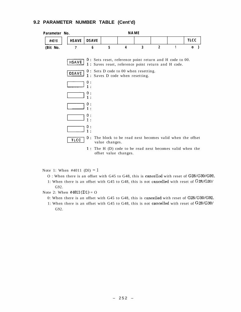
9.2 PARAMETER NUMBER TABLE (Cent’d)
Parameter No. N A M E
ml HSAVE DSAVE TLCC
(Bit No. 7 6 5 4 3 2 1 o )
Note 1: When #4011 (Dl)
Sets reset, reference point return and H code to 00.Saves reset, reference point return and H code.
Sets D code to 00 when resetting.Saves D code when resetting.
The block to be read next becomes valid when the offsetvalue changes.
The H (D) code to be read next becomes valid when theoffset value changes.
=1
O : When there is an offset with G45 to G48, this is cancelled with reset of G28/G30/G92.1: When there is an offset with G45 to G48, this is not cancelled with reset of G28/G30/
G92.Note 2: When #4011 (Dl) = O
0: When there is an offset with G45 to G48, this is cancelled with reset of G28/G30/G92.1: When there is an offset with G45 to G48, this is not cancelled with reset of G28/G30/
G92.
– 2 5 2 –

Parameter No. N A M E
01#401 1 MABIN MANINC MANAXS G45HD
(Bit No. 7 6 5 4 3 2 1 o )
Manual absolute function not disregarded relative toincremental commands.
Disregards manual absolute function relative toincremental commands.
Manual absolute valid when there is an axis commandin a block in which no incremental amount is generated.
Maunal absolute invalid when there is an axis commandin a block in which no incremental amount is generated.
Maunal absolute valid when there is no axis commandin a block in which incremental amount is generated.
Manual absolute invalid when there is no axis commandin a block in which incremental amount is generated.
G45 to G48 offset number command is possible withD code only.
G45 to G48 offset number command is possible withH code only.
– 2 5 3 –

9.2 PARAMETER NUMBER TABLE (Cent’d)
Parameter No. N A M E
m[G54PJ CMPCX3 WSTSGN WSTQIK
(Bit No. 7 6 5 4 3 2 1 o )
m O : Sets “J” as the work coordinate system settingexpansion address.
1 : Sets “P” as the work coordinate system settingexpansion address.
m O : Tool radius offset C startup cancel specification I.1: Tool radius offset C startup cancel specification X3.
m O : Inverts incremental input code to work coordinate systemshift amount.
1 : Does not invert incremental input code to work coordi-nate system shift amount.
m O : Becomes valid from the next command when theamount of work coordinate system shift is changed.
1 : Becomes valid from the next block when the amount ofwork coordinate system shift is changed.
– 2 5 4 –

Parameter No. N A M E
mlNKCHK KCHK CM PCOFS CM PCDIR CMPCAB
(Bit No. 7 6
1 :
=0’1 :
B“1 :
5 4 3 2 1 0)
Corrects automatically with interference check.Sets alarm with interference check.
Without interference check function .With interference check function.
Change in amount of compensation is valid at theterminal point.
Change in amount of compensation is valid at thestarting point.
Changes direction of compensation (G41/G42) atintersections.
Changes direction of compensation (G41/G42) atthe start and end.
Uses B type compensation method for startup andcancel operations.
Uses A type compensation method for startup andcancel operations.
– 2 5 5 –

9.2 PARAMETER NUMBER TABLE (Cent’d )
Parameter No. N A M E
ml G60DR5 G60DR4 G60DR3 G60DR2 G60DR1
(Bit No. 7 6 5 4 3 2 1 0)
m O : Unidirectional positioning direction of 5th axis G60 plus.1 : Unidirectional positioning direction of 5th axis G60 minus.
m O : Unidirectional positioning direction of 4th axis G60 plus.1 : Unidirectional positioning direction of 4th axis G60 minus.
m O : Unidirectional positioning direction of Z-axis G60 plus.1 : Unidirectional positioning direction of Z-axis G60 minus.
O : Unidirectional positioning direction of Y-axis G60 plus.a.’60D ’2 1 “ Unidirectional positioning directiorl of Y-axis G60 minus.
m O : Unidirectional positioning direction of X-axis G60 plus.1 : Unidirectional positioning direction of X-axis G60 minus.
Parameter No. N A M E
ml PRTSPD SERHLD ERDSTAP ERDGOO DWLER PSETON G02RCHK PRSSW
(Bit No. 7 6 5 4 3 2 1 0)
IPRTSPDI
ISERHLDI
mlERDGOOl
m
m
o:1 :
0 :
1 :
0:1 :
0 :
1 :
0:1 :
0:1 :0 :1 :
0 :1 :
Sets program restart approach speed to JOG again.Sets program restart approach speed to rapid traverse.
Does not display peak value of synchronous error ofspindle and Z-axis during solid tap.
Display peak value of synchronous error of spindle andZ-axis during solid tap.
Sets GOO error detect to OFF during solid tap.Sets GOO error detect to ON during solid tap.
Sets to IN – POSITION WAIT with GOO and GO1 ~ GOOcommands.
Does not set to IN – POSITION WAIT with GOO andGol ~ GOO commands.
Sets error detect to OFF when dwell execution ends.Sets error detect to ON when dwell execution ends.
PSET is not waited for at exit from shape offset mode.PSET is waited for at exit from shape offset mode.
Does not check circular arc radius allowance.Check circular arc radius allowance.
Enters program restart mode by 1/0.Enters program restart mode by soft keys.
– 2 5 6 –

Parameter No. N A M E
01#4016 CANTP2 CANTP1 CANGOO
I(Bit No. 7 6 5 4 3 2 1 0)
m O : Reverses spindle without outputting M05 at the bottomof the hole in canned cycles G74 and G84.
1: Reverses spindle by outputting M05 at the bottom of the. hole in canned cycles G74 and G84.
m O : Sets M output in canned cycles G74 and G84 as inversionof M code prior to the canned cycle.
1: Sets M output in canned cycles G74 and G84 as G74 : M03and G84 : M04.
O : Sets GOO as the positioning operation of the canned= cyc~e
1: Sets positioning operation of the canned cycle to thecurrently selected 01 group code (GOO or GO1 ).
– 2 5 7 –

9.2 PARAMETER NUMBER TABLE (Cent’d)
Parameter No. N A M E
ml PITDWL G76DWL TPOVR G76M05
(Bit No. 7 6 5 4 3 2 1 o )
O : Pitch dwell time #401 invalid.PITDWL 1: Pitch dwell time #401 valid.
O : G76/G77 dwell time #400 invalid.G76DW L 1 1: G76/G77 dwell time #400° valid.
m O : Spindle override during execution of G74 and G84 tabcycle is fixed during initial read.
1: Spindle override during execution of G74 and G84 tabcycle is 100% fixed.
m O : Does not output M05 before outputting M19 with G76/G77.1: Outputs M05 before outputting M19 with G76/G77.
– 2 5 8 –
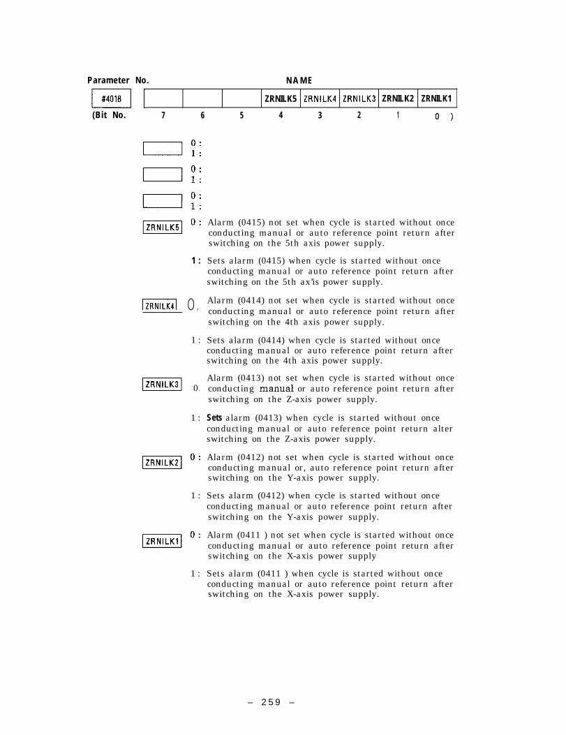
Parameter No. N A M E
mlZRNILK5 ZRNILK4 ZRNILK3 ZRNILK2 ZRNILK1
(Bit No. 7 6 5 4 3 2 1 0)
1 :
m 0’
1 :
m 0’
1 :
1 :
m’:1 :
Alarm (0415) not set when cycle is started without onceconducting manual or auto reference point return afterswitching on the 5th axis power supply.
Sets alarm (0415) when cycle is started without onceconducting manual or auto reference point return afterswitching on the 5th ax’is power supply.
Alarm (0414) not set when cycle is started without onceconducting manual or auto reference point return afterswitching on the 4th axis power supply.
Sets alarm (0414) when cycle is started without onceconducting manual or auto reference point return afterswitching on the 4th axis power supply.
Alarm (0413) not set when cycle is started without onceconducting manual or auto reference point return afterswitching on the Z-axis power supply.
Sets alarm (0413) when cycle is started without onceconducting manual or auto reference point return alterswitching on the Z-axis power supply.
Alarm (0412) not set when cycle is started without onceconducting manual or, auto reference point return afterswitching on the Y-axis power supply.
Sets alarm (0412) when cycle is started without onceconducting manual or auto reference point return afterswitching on the Y-axis power supply.
Alarm (0411 ) not set when cycle is started without onceconducting manual or auto reference point return afterswitching on the X-axis power supply
Sets alarm (0411 ) when cycle is started without onceconducting manual or auto reference point return afterswitching on the X-axis power supply.
– 2 5 9 –

9.2 PARAMETER NUMBER TABLE (Cent’d )
Parameter No. N A M E
(Bit No. 7 6 5 4 3 2 1 o )
– 2 6 0 –

Parameter No. N A M E
ml SMCRO MMCRO MPRM BMCRSBK Unusable Unusable Unusable
(Bit No. 7 6 5 4 3 2 1 o )
m“’1 :
mo:1 :
When multiple S is commanded to the same block in Scode macro, the 2nd S command and beyond becomesnormal S code.
When multiple S is commanded to the same block in Scode macro, the 2nd S command and beyond becomesargument.
When multiple M is commanded to the same block in Mcode macro, the 2nd M command and beyond becomesnormal M code.
When multiple M is commanded to the same block in Mcode macro, the 2nd M command and beyond becomesargument.
No argument is specified in M code macro program.Argument is specified in M code macro program.
Validates single-block switch at execution of B macro.Invalidates single-block switch at execution of B macro.
Always set O to use system.
Always set O to use system.
Always set O to use system.
– 261 –

9.2 PARAMETER NUMBER TABLE (Cent’d)
Parameter No. N A M E
(Bit No. 7 6 5 4 3 2 1 0)
Parameter No. N A M E
mlZRNE5 ZRNE4 ZRNE3 ZRNE2 ZRNE1
(Bit No. 7 6 5 4 3 2 1 o )
m O : 5th axis reference point return invalid (Alarm 241 occurs).1: 5th axis reference point return valid.
m O : 4th axis reference point return invalid (Alarm 241 occurs).1: 4th axis reference point return valid.
m O : Z-axis reference point return invalid (Alarm 241 occurs).1 : Z-axis reference point return valid.
m O : Y-axis reference point return invalid (Alarm 241 occurs).1: Y-axis reference point return valid.
O : X-axis reference point return invalid (Alarm 241 occurs).ml:x.axis reference point return valid.
– 2 6 2 –

Parameter No. N A M E
m~(Bit No. 7 6 5 4 3 2 1 o )
Parameter No. N A M E
ml PLBK5 PLBK4 PL8K3 PLBK2 PLBK1
(Bit No. 7 6 5 4 3 2 1 o )
m O : 5th axis playback write-in invalid.1: 5th axis playback write-in valid.
m O : 4th axis playback write-in invalid.1: 4th axis playback write-in valid.
m O : Z-axis playback write-in invalid.1: Z-axis playback write-in valid.
n O : Y-axis playback write-in invalid.p L B K 2 1 : Y-axis playback write-in valid.
m O : X-axis playback write-in invalid.1: X-axis playback write-in valid.
– 2 6 3 –

9.2 PARAMETER NUMBER TABLE (Cent’d )
Parameter No. N A M E
ml PLBKT PLBKS PLBKF
(Bit No.
Parameter No.
\ #4026 I
7 6 5 4 3
0: Playback T write-in invalid.1 : Playback T write-in valid.
O : Playback S write-in invalid.1: Playback S write-in valid.
O : Playback F write-in invalid.1: Playback F write-in valid.
o:1 :
0:1 :
0:1 :
0:1 :
0:1 :
N A M E
2 1 o )
\ #4028 I1 I
– 2 6 4 –

Parameter
I #4029 I
(Bit No.
Parameter
mm
No. N A M E
TLSKP OFSHD
7
1
[
I
Im
No.
6
0:1 :
0 :1 :
0 :1 :
0 :1 :
0 :1 :
0 :1 :
0 :
1 :
0 :1 :
5 4 3
Makes currently selected toolby tool life control.
Makes specified tool group inlife control.
Use offsetUse offset
2 1 0)
group in the skipped state
the skipped state by tool
memory for H/D in common,memory for H/D separately.
N A M E
– 2 6 5 –

9.2 PARAMETER NUMBER TABLE (Cent’d)
Parameter No. NAME.
EIA code punch pattern #
EIA code punch pattern [ I
EIA code punch pattern ]
EIA code punch pattern * I
EIA code punch pattern = I
EIA code punch pattern (
I EIA code punch pattern ) I
m I EIA code punch pattern ,
m
m
m
EIA oode punch pattern ‘ I
I EIA oode punch pattern “ IHole patternof special character EIAused inuser macro.Setting: Considers hole pattern in binary andconverts thisto
decimal value.
Tool life management group command T-number offset.Setting : T command value–#4110 x 1000 = tool life management
groupExample : When 1 is set for #4110, TIOO1 to TIoI5 are used as tool
life management T commands.Setting range : 0 to 9
mm
– 2 6 6 –

Parameter No. N A M E
ml
– 2 6 7 –

9.2 PARAMETER NUMBER TABLE (Cent’d )
Parameter No. N A M E
mm
mm
mm
mCoordinate system specification when conducting work coordinatesystem shifts during reference point return when power is switchedon.Setting range : 54 to 59
mm
I E 1A code punch pattern < I
[EIA code punch pattern >
I EIA code punch pattern ; IEIA code punch for special characters used in macro programSetting : Decimal value converted from binary value represented by
punch pattern
– 2 6 8 –

Parameter
B
mmmm
I #4157 I
m
Mmm
No. N A M E
I I
I I
I I
[
Specification of high speed operating mode.Setting : 0: Unconverted
1 : Conversion in specified sections2: Automatic conversion
Setting range : 1 to 2
High speed conversion start command code (input with ASCII)when the operating mode of high speed mode operation isconverted for specified sections.(Example)
HON #4161 72#4162 79#4163 78
– 2 6 9 –

9.2 PARAMETER NUMBER TABLE (Cent’d)
Parameter No. N A M E
m
I #4167 I
Mm
mI #4173 I
mI #41 75 I
mmm
‘ High speed conversion end command code (input with ASCII)when the operating mode of high speed mode operation isconverted for specified sections.
> (Example)HOF #4164 72
#4165 79) #4166 70
I
Segment type of high speed mode operationSetting : 1 lms
2 2ms4 4ms
Setting range : 4
J
– 2 7 0 –

Parameter No. N A M E
m~
– 271 –

9.2 PARAMETER NUMBER TABLE (Cent’d )
Parameter No. N A M Emmm
I
I I
1 I
m
Hmm
I (3) I
Ml “) 1
I (8) I
m I “) I
mI I
mmm
I (lo) I
Advance read stop M code.Setting range : 0 to 999
I
– 2 7 2 –

Parameter No. N A M E
mmm
Hmm
I I
1
I
I I
L I
I
1I I
I 1
I
L ,
– 2 7 3 –

9.2 PARAMETER NUMBER TABLE (Cent’d )
Parameter No. N A M E
J
H
mm
m
mmI #4448 I
mm
I 1I
II I
I I
Minute circular skip value of nose R andSetting : 1 = Minimum input unit.Setting range : 0 to 32767
diameter compensation.
– 2 7 4 –

Parameter No.
mmI Z-axis I
I #4454 I \ 4thaxis I
I #4455 II I
m
Reference point return travel distance.Setting : 1 = 0.001 mm, 0.0001 in or 0.001 degSetting range : 0 to 32767
I 5th axis I
Override at G60.Setting : 1 = O.001.mm, 0.0001 in or 0.001 degSetting range : 0 to 32767
I J
I
– 2 7 5 –

----- -——— —- —- — ,— . .9.2 PARAMETER NUMBER
Parameter No.
TABLE (Cent’dJ
N A M E
mmmm
I (5) I
I (6) I
I (7) I
I (8) I
I #4489 I I (lo) I
G code macro call.Setting range : 1 to 999
– 2 7 6 –

Parameter No.
I #4490 I I (11) I
I #4492 I
I googs I I (14) II #4494 j I (15) I
m I (16) I
#4496 I
m I (18) I
mm
I (19) I
I II #4501 I
G code macro call.Setting range : 1 to 999
– 2 7 7 –

9.2 PARAMETER NUMBER TABLE (Cent’d)
I #4506 I
mmI #4509 I I (6) I
mmm
mm
I (10) I
I (13) I
m
N A M E
M code macro call.Setting range : 1 to 999
– 2 7 8 –

Parameter No.
m
I #4522 I
m
m
H
mmmB
Hm
I (18) I
I (20) I
I (22) I
M code macro call.Setting range : 1 to 999
J
– 2 7 9 –

9.2 PARAMETER NUMBER TABLE (Cent’d)
Parameter No. N A M E
I I
IM I I
I Y-axis I
Reference point return phase C shift amountSetting 1 =0.001 mm, 0.000 in or 0.001 degSetting range : –32767 to 32767
I 5th axis I
I #4800 I
I X-axis I
mAutomatic coordinate system setting valuewhen inputting in mm.
Setting :1 = Minimum input unit of millimeter systemSetting range : 0 to *999999999
D#4803
m ] 4th axis I
I 5th axis I
I 84810 I
B
I Y-axis IAutomatic coordinate system setting valuewhen inputting in inch.Setting : 1 = Minimum input unit of inch systemSetting : 0 to *999999999
\ Z-axis I
m I 4th axis I
m I 5thaxis I
– 2 8 0 –

Parameter No. N A M E
Allowable range in circular setting.
I #4821 I
B
I #4830 I
H
Setting : 1 = Minimum input unitSetting range : 0 to t 999999999
I I
I I
I I
I I
II I
I I
1 I
I 1
I
– 281 –

9.2 PARAMETER NUMBER
Parameter No.
TABLE (Cent’d )
N A M E
m
I #4847 I
I (1) I
I (6) I
I (7 ) I
I (9) I
G code macro call programSetting range : 1 to 99999
– 2 8 2 –

Parameter No.
I #4854 I 1 (15) I
——
——
I #4863 I I (24) I
G code macro call program No.Setting range : 1 to 99999
– 2 8 3 –

9.2 PARAMETER NUMBER TABLE (Cent’d)
Parameter No. N A M E
m
I I
mmmm M code macro call program No.
Setting range : 1 to 99999I (8) I
m I (9) I
I (10) I
m I (11) I
I (13) I
I (14) I
I (15) I
– 2 8 4 –

Parameter No.
mm
m
HI #4888 \
I #4895 I
mI (18) I
I (19) I
I (20) I
I (22) I
I (23) I
I (24) I
N A M E
M code macro call program No.Setting range : 1 to 99999
S code macro call specification.Setting range : 0 or called program number
T code macro call specification.Setting range : 0 or called program number
B code macro call specification.Setting range : 0 or called program number
– 2 8 5 –

9.2 PARAMETER NUMBER TABLE (Cent’d )
Parameter No. N A M E
I #4898 I
m
I
– 2 8 6 –

Parameter
m(Bit No.
No. N A M E
ESPRST RWDOUT STUD
7 6 5 4 3 2 1 0)
m“’1 :
m“’1 :
Parameter No.
RST output not set to ON when ESP input is ON.Sets RST to ON when ESP input is ON.
Outputs rewind when setting NC program to rewind bymeans of reset and rewind signals.
Outputs rewind when setting NC program to rewind bymeans of reset and rewind signals.
Cycle start is valid when the cycle start signal changesfrom “o” t o “ 1 ” .
Cycle start is valid when the cycle start signal changesf r o m “1” t o ‘ O ” .
N A M E
ml EXDBND
(Bit No. 7 6 5 4 3 2 1 0)
o:1 :
0 :1 :
0:1 :
0 :1 :
0 :1 :
0 :1 :
0 :1 :
0: Sets data type of external data input as BIN.1: Sets data type of external data input as BCD.
– 2 8 7 –

9.2 PARAMETER NUMBER TABLE (Cent’d )
Parameter No. N A M E
ml(Bit No. 7 6 5 4 3 2 1 0)
Parameter No. N A M E
m~(Bit No. 7 6 5 4 3 2 1 o )
– 288 –

Parameter No. N A M E
m~(Bit No. 7 6
Parameter No.
5 4
N A M E
3 2 1 0)
(Bit No. 7 6 5 4 3 2 1 0)

9.2 PARAMETER NUMBER TABLE (Cent’d )
Parameter
\ #5006 \
m
m
No. N A M E
Parameter No. N A M E
I #5010 I
( B i t No.
SK IPSEL FC230 DINMON SK IPE1
7
lsKIpSELl
m
I
m
6
0:1 :
0 :1 :
0 :
1 :
0 :1 :
0 :1 :
0 :1 :
0 :1 :
0 :1 :
5 4 3 2
Enable manual skip function.Enable skip B function.
Uses FC230B for motion monitor module.Uses FC230 for motion monitor module.
Turns on the sensor by changing direction“o” to “l”.
Turns on the sensor by changing direction“l” to “o”.
1st skip signal invalid.1st skip signal valid.
1 o )
monitor from
monitor from
– 2 9 0 –

Parameter No. N A M E
ml SKIPD1
(Bit No. 7 6 5 4 3 2 1 0)
m O : 1 st skip signal valid when changed from “ 1” to “O”.1: 1 st skip signal valid when changed from “O” to “1”.
Parameter No. N A M E
mlESVON
(Bit No. 7 6 5 4 3 2 1 0)
O : Servo power goes on when the POWER INPUT button ism ,,,,.,..
1: Servo power is turned on by an ~ternal input.
– 291 –

9.2 PARAMETER NUMBER TABLE (Cent’d)
Parameter
\ #5013 ]
( B i t No.
Parameter
[ #5015 I
I #5016 I
m
No. N A M E
OFSSEL OFSXY
No.
o:1:
0:1 :
0 :1 :
0 :1 :
0 :1 :
0 :
1 :
0 :1 :
0 :
1 :
6 5
Validateseffective.
4 3 2 1 0)
TLM when both offset printer and TLM are ,
Validates offset printer when both offset printer and TLMare effective.
Tool measurement at X-axispresetter.
Tool measurement at Y-axispresetter.
N A M E
direction in offset
direction in offset
– 2 9 2 –

Parameter
mm
mm
Time from base block cancellation to brake release after servopower is turned on.Setting : l=lmsSetting range : 0 to 32767
/ Y-axis I
\ 5th axis I
Time from falling of ESPSetting : I=lmsSetting range : 0 to 32767
to OFF of base block.
mTime from sending of M, S, T code to sending of MF, SF and TF.Setting : 1 = 1 ms (Input multiple of 4)Setting range : 0 to 32767
I [
m
mH 1
– 2 9 3 –

9.2 PARAMETER NUMBER TABLE (Cent’d)
Parameter No. N A M E
m
mmm
I J
Software switch input keep memory starting No.Setting range :7000 to 7999
Software switch output keep memory starting No.Setting range :7000 to 7999
Program restart switch keep memory No.Setting range :7000 to 7999
1 I
Manual skip signal keep memory No.Setting range :7000 to 7999
– 2 9 4 –

Parameter No. N A M E
BIPIT5 PIT4 PITZ PITY P I T X
(Bit No. 7 6 5 4 3 2 1 0)
m O : Pitch error invalid (5th axis).1: Pitch error valid (5th axis).
m O : Pitch error, invalid (4th axis).1: Pitch error valid (4th axis).
m O : Pitch error invalid (Z-axis).1: Pitch error valid (Z-axis).
m O : Pitch error invalid (Y-axis).1: Pitch error valid (Y-axis).
m O : Pitch error invalid (X-axis).1: Pitch error valid (X-axis).
Parameter No. N A M E
mlPERlAB
(Bit No. 7 6 5 4 3 2 1 0)
Incremental setting of pitch error offset amount.Absolute setting of pitch error offset amount.
– 2 9 5 –

9.2 PARAMETER NUMBER TABLE (Cent’d)
Parameter No. N A M E
WISTL5 ST L4 STL3 STL2 STL1
(Bit No. 7 6 5 4 3 2 1 0)
m O : Checks 5th-axis 1st inhibit area stored stroke limit.1: 5th-axis 1st inhibit area stored stroke limit not checked.
m O : Checks 4th axis 1st inhibit area stored stroke limit.1: 4th axis 1st inhibit area stored stroke limit not checked.
m O : Checks Z-axis 1st inhibit area stored stroke limit.1: Z-axis 1st inhibit area stored stroke limit not checked.
m O : Checks Y-axis 1st inhibit area stored stroke limit.1: Y-axis 1st inhibit area stored stroke limit not checked.
m O : Checks X-axis Ist inhibit area stored stroke limit.1: X-axis 1st inhibit area stored stroke limit not checked.
Parameter No. N A M E
m~(Bit No. 7 6 5 4 3 2 1 o )
– 2 9 6 –

Parameter No. N A M E
ml RSTL5 RSTL4 RSTL3 RSTL2 RSTL1
(Bit No. 7 6 5 4 3 2 1 0)
m O : No stroke check when 5th axis rotating.1 : Stroke checked when 5th axis rotating.
m O : No stroke check when 4th axis rotating.1: Stroke checked when 4th axis rotating.
m O : No stroke check when Z-axis rotating.1 : Stroke checked when Z-axis rotating.
m O : No stroke check when Y-axis rotating.1 : Stroke checked when Y-axis rotating.
m O : No stroke check when X-axis rotating.1 : Stroke checked when X-axis rotating.
Parameter No. N A M E
ml(Bit No. 7 6 5 4 3 2 1 0)
– 2 9 7 –

9.2 PARAMETER NUMBER TABLE (Cent’d)
Parameter No. N A M E
01#6006 DTCH5 DTCH4 DTCHZ DTCHY DTCHX
(Bit No. 7 6 5 4 3 2 1 o )
m O : OFF when 5th axis detached.1: ON when 5th axis detached.
m O : OFF when 4th axis detached.1: ON when 4th axis detached.
m O : OFF when Z-axis detached.1: ON when Z-axis detached.
m O : OFF when Y-axis detached.1: ON when Y-axis detached.
m O : OFF when X-axis detached.1: ON when X-axis detached.
Parameter No. N A M E
m~(Bit No. 7 6 5 4 3 2 1 o )
– 2 9 8 –

Parameter
m(Bit No.
Parameter
m(Bit No.
No. N A M E
ITLMTYP
5 4 3 2 1 o )
m“’1 :
TLM measurement considered measurement of amountof movement.
TLM measurement considered measurement of residualamount.
N A M E
I7 6 5 4 3 2 1 0)
– 299 –

PARAMETER NUMBER TABLE (Cent’d)
Parameter No. N A M E
mm I X-axis I
Mm Pitch error offset multiplying factor.
Setting range : 0 to 3I Z-axis I
mm I 5th axis I
1mm I (1) I
1 = X-axis2 = Y-axis3 = Z-axis
2nd stroke limit check axis No.Setting range : 0 to 3I #6112 I I (2) I
m I (3) I
1 = X-axis2 = Y-axis3 = Z-axism 3rd stroke limit check axis No.
Setting range : 0 to 3
m
1 = X-axis2 = Y-axis3 = Z-axis
4th stroke limit check axis No.Setting range : 0 to 3m I (2) I
m
– 3 0 0 –

Parameter No.
P I
II I I
I I
II 1 I J
I 1 1 I
I1 I I I
I
– 301 –

9.2 PARAMETER NUMBER TABLE (Cent’d )
Parameter No. N A M EmII #6139 I
m I I
I X-axis I
mm I Z-axis I Pitch error start memory No.
m I 4th axis I
m I 5th axis I
Setting example of pitch error start memory No.
Parameter #
#6000 DO to#6000 D4
#6801 to #6805
#6001 DO
#6421 to #6425
#6411 to #6415
#6401 to #6405
Poooo to P1151
#6101 to #6105
Details, remarksNo. Item Axis
Pitch erroroffset
“O” = Invalid“1” = ValidXtop
Intercal ofoffset
ABS/INC
Over 10000“1”=1 PulseXtop
/“O” = Incremental setting“1” = Absolute wtting
Origin point No.of offset Xtop
Max. point ofOffst Xtop —
Min. point ofoffset Xtop
1 to *127“l” = 1 PulseXtop
lto3“1” = Tool life xale
Scale ofoffset Xtop
– 3 0 2 –

( Setting example )
A write example of pitch error offset in the X-axis is shown below.
PITCH ERROROFFSET(PULSES)
REFERENCEPOINT
2-
1-
11 ~,,,0 f*X-axi
-1 -
-2 -
AbsoluteSetting
() +1 +1 –2 –1 0 +1 +1 +1 +2 +2
Offset mentalSetting –1 o +3 –1 –1 o +1 o () +1 o
OffsetParameter at 0000 OOQ1 0002 0003 0004 0005 0006 0007 CQ08 0009 N1OEach Point
Example of Writing to X-axis
– 3 0 3 –

9.2 PARAMETER NUMBER TABLE (Cent’d)
When conditions are as follows in the diagram, the parameters will be set as
shown below.
Conditions
Offset interval : 10000 pulse
ABC/INC : Incremental
Offset points of X-axis : 100 points
< parameter setting > Offset amount parameter of each point
X–axis
Note :
Origin point No. of offset Poooo –1 7#6421 I 5 Poool o
Min. point of POO02 +3
offset POO03 –1POO04 –1
Max. point of offset POO05 o
#6411 \ 99POO06 +1POO07 o
I offset interval
~
POO08 oPOO09 +1Poolo o
ABSIINC Setting
~:
PO098Write in the offset of reference PO099point for each axis so that itbecomes O.
PO1OO -
::
“
– 3 0 4 –

< Pitch error setting example of rotating axis ~
When the offset interval is 45000 pulses (each rotation divided into 8 parts) as shown in the
diagram, each parameter is set as follows.
Max. point o f
Po 16 .
compe=””t
Origin point No. and alsoPol 50
<
.L, ==cion O.(l) Min. point of compensation
?~t?~6) P0151l . ( l )
56(1)
s.(l)w~:P0155
4 . ( 1 )~ Amount of offset of INC setting.
Amount of offset of ABS setting.
Offset amount parameter of
Origin point No.each point
offset Parameter ABS setting INC setting
~
7
P0150 o 0
Min. point of P0151 1 1offset P0152 2 1~ P0153 3 1Max. point ofoffset P0154 4 1
~
\
P0155 5 1
P0156 6 1
Interval of offset P0157 o - 6
~
– 3 0 5 –

9.2 PARAMETER NUMBER TABLE (Cent’d )
Parameter No. N A M E
n#6410 I
mPitch error end memory No.
mm ] 5th exis I
I #6420 I
I Y-axis I
Reference point memory No. with pitch erroroffset.
I #6423 I
mm
IHm
I 1
– 3 0 6 –

Parameter No. N A M E
I #6439 I
mm
Hmm
I I
I1
I I
I 1I
I
1
1
I X-axis I
I Z-axis I
H
Pitch error offset interval.Setting : 1 = 0.001 mm, 0.0001 in. or 0.001 degSetting range : 0 to 999999999
– 3 0 7 –

PARAMETER NUMBER TABLE (Cent’d )
Parameter No. N A M E
m I
mI #6812 I
2nd reference point position.Setting : 1 = 0.001 mm, 0.0001 in. or 0.001 degSetting range : 0 to t999999999m
I 4th axis I
m
mmm I Y-axis I
3rd reference point position.Setting : 1 = 0.001 mm, 0.0001 in. or 0.001 degSetting range : 0 to *999999999
m I 5th axis I
I
m I X-axis I
I #6832 I
4th reference point position.Setting : 1 = 0.001 mm, 0.0001 in. or 0.001 degSetting range : 0 to *999999999
mI #6834 I
m
– 3 0 8 –

Parameter No. N A M E
n#6840
I #6841 I
I I
\ #6844 I
B
HI #6847 \
Length direction reference value Xo in offset presettermeasurement.Setting : 1 =O.OOlmm or O. 0001 in.Setting range : 0 to i 999999999
Radius direction reference value Zo in offset presettermeasurement.Setting : 1 = 0.001 mm or 0.0001 in.Setting range : 0 to t999999999
I z- 1
Probe radius for work presetter measurement.Setting : 1 = 0.001 mm or 0.0001 in.Setting range : 0 to *999999999
Work setter measurement possible retraction amount.Setting : 1 = 0.001 mm or O.0001 in.Setting range : 0 to +999999999
Work setter measurement separation amount.Setting : 1 = 0.001 mm or 0.0001 in.Setting range : 0 to +999999999
– 3 0 9 –

9.2 PARAMETER NUMBER TABLE (Cent’d )
Parameter No. N A M E
m
I #6863 I
X-axis
I Y-axis I
Z-axis
4th axis
5th axis
Pitch error offset stroke (maximum)Setting : 1 = 0.001 mm or 0.001 degSetting range : 0 to *999999999
X-axis I
I
Y-axis
Z-axis I
4th axis I5th axis I
Pitch error offset stroke (minimum)Setting : 1 = 0.001 mm or 0.001 degSetting range : 0 to *999999999
1 X-axis I
Y-axis II #6883 I
mm
Z-axis
4th axis
5th axis
Pitch error offset reference positionSetting : 1 = 0.001 mm or 0.001 degSetting range : 0 to *999999999
– 3 1 0 –

Parameter
m
m
mm
m
No. N A M E
I X-axis I
I X-axis II I
Stroke limit plus.Setting: 1 = 0.001 mm, 0.0001 in. or 0.001 degSetting range : 0 to t999999999
I #6912 ] I Y-axis I
mI 4th axis I
Stroke limit minus.Setting : 1 = 0.001 mm, 0.0001 in.Setting range : 0 to k999999999
or 0.001 deg
– 311 –

9.2 PARAMETER NUMBER TABLE (Cent’d)
Parameter No. NAME
ml#8000 ZRNST8 ZRNST7 ZRNST6 ZRNST5 ZRNST4 ZRNSTZ ZRNSTY ZRNSTX
(Bit No. 7 6 5 4 3 2 1 0 )
Referencepoint settingcompleted axes
H O: Absolute position detecting function 8th axis reference point not completed.1: Absolute position detecting function 8th axis reference point completed.
H O: Absolute position detecting function 7th axis reference point not completed.1: Absolute position detecting function 7th axis reference point completed,
-0: Absolute position detecting fmction Cth axis reference point not completed.1: Absolute position detecting function Gth axis reference point completed.
m O: Absolute position detecting function 5ti axis reference point not completed.1: Absolute position detecting function 5ti axis reference point completed.
m O: Absolute position detecting function 4tb axis reference point not completed.1: Absolute position detecting function 4th axis reference point completed.
m O: Absolute position detecting function Z-axis reference point not completed.1: Absolute position detecting function Z.axis reference point completed.
m O: Absolute position detecting function Y-axis reference point not completed.1: Absolute position detecting function Y-axis reference point completed.
=O: Absolute position detecting function X-axis reference point not completed.1: Absolute position detecting function X-axis reference point completed.
Parameter No. NAME
ml POSER8 POSER7 POSER6 POSER5 POSER4 POSERZ POSERY POSERX
(Bit No. 7 6 5 4 3 2 1 0 )
O: Absolute position detecting function 8th axis reference point setting not provided
( - 1: Absolute position detecting function 8th axis reference point setting provided.
m O: Absolute position detecting function 7th axis reference point setting not provided.1: Absolute position detecting function 7th axis reference point setting provided.
m O: Absolute position detecting function dtb axis reference point setting not provided.1: Absolute position detecting function Gti axis reference point setting provided.
Position ImO: Absolute position detecting function 5ti axis reference point setting not provided.1: Absolute Position detecting fwction 5th axis reference point setting provided.
shiftedstatas
O: Absolute position detecting function 4ti axis reference point setting not provided.m -
1 :’Absolute position detecting function 4tb axis reference point setting provided.
m O: Absolute position detecting function Z-axis reference point setting not provided.1: Absolute position detecting function Z-axis reference point setting provided.
m O: Absolute position detecting function Y-axis reference point setting not provided.1: Absohrte position detecting function Y-axis reference point setting provided.
[m O: Absolute position detecting function X-axis reference point setting not provided.1: Absolute position. detecting ftiction X-axis reference point setting Provided.
– 3 1 2 –

Parameter No. NAME
ml#8002 ZRSET1 ZRSETO
(Bit No. 7
I
I
I
m
H
o:1:
0:1:
)
6
0:1:
0:1:
0:1:
0:1:
0:1:
0:1:
Absolutepositiondetectingfunctionreferencepoint settingmethod
5 4 3 2 1 0 )
31 DO
o 0 Manual low-speed type reference pointreturn method
o ~ Floating machine reference point manualsetting method
~ o Machine reference position fixed referencer)oint setting method
1 1 Automatic reference point setting method
I Y-axis I
I Z-axis I
[ 4th axis I
m
Reference point shift fine adjusting amountSetting : 1=0.001 mm or 0.001 degSetting range : – 32768 to 32767
313 –

PARAMETER NUMBER TABLE (Cent’d )
Parameter
HMm
B
mml Position shift limiting value at power ON
Z–axis Setting : 1=0.001 mm or 0.001 degSetting range :0 to 32767
mm
B
mB
B
– 3 1 4 –

Parameter No. N A M E
mB
m
H
mm
1 I
I
I X-axis I
] 4th axis I
Current loop cut-off frequency offset valueSetting : 1=1 HzSetting range : – 500 to +500
I J
– 3 1 5 –

PARAMETER NUMBER TABLE (Cent’d)
N A M EParameter No.
m I Y-axis II I
m Phase U current offset valueSetting range : — 500 to +500I I
] 4th axis I
m
mm I X-axis I
I I
m I Y-axis I
Phase V current offset valueSetting range : – 500 to +500
Z–axis
m 1 ,
mm
– 316 –

— .Parameter
m
I #8463 I
mB
m
m
B
m
No. N A M E
1X-axis
Y-axis I
Z-axis
4th axis
I5th axis
Servopack format parameterSetting range : 0 to 7
-, - Set “O” when analog AMP is used.
~
\ Z-axis I
I 5th axis I
Machine position at power OFFSetting : 1=0.001 mm or 0.001 degSetting range :0 to *999999999
1 I
I ,
– 317 –

PARAMETER NUMBER
‘b’
E
N A M E
Offset value at reference point settingSetting : 1=1 pulseSetting range :0 to +999999999
II X-axis I
I Z-axis I
m/ 5th axis I
Reference point shift valueSetting : 1=0.001 mm or 0.001 degSetting range :0 to t999999999
I I
– 318 –
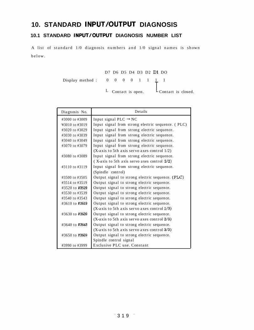
10. STANDARD lNPUT/OUTPUT DIAGNOSIS
10.1 STANDARD lNPUT/OUTPUT DIAGNOSIS NUMBER LIST
A list of standard 1/0 diagnosis numbers and 1/0 signal names is shown
below.
D7 D6 D5 D4 D3 D2 D1 DO
Display methed : 0 0 0 0 1 1 1 1
L Contact is open. I Contact is closed.
Diagnosis No. Details
#3000 to #3009 Input signal PLC + NC‘#3010 to #3019 Input signal from strong electric sequence. ( PLC)#3020 to #3029 Input signal from strong electric sequence.#3030 to #3039 Input signal from strong electric sequence.#3040 to #3049 Input signal from strong electric sequence.#3070 to #3079 Input signal from strong electric sequence.
(X-axis to 5th axis servo axes control 1/2)#3080 to #3089 Input signal from strong electric sequence.
( X-axis to 5th axis servo axes control 2/2)#3110 to #3119 Input signal from strong electric sequence.
(Spindle control)#3500 to #3505 Output signal to strong electric sequence. (PLC)#3514 to #3519 Output signal to strong electric sequence.#3520 to #3529 Output signal to strong electric sequence.#3530 to #3539 Output signal to strong electric sequence.#3540 to #3543 Output signal to strong electric sequence.#3610 to #3619 Output signal to strong electric sequence.
(X-axis to 5th axis servo axes control 1/3)#3630 to #3639 Output signal to strong electric sequence.
(X-axis to 5th axis servo axes control 2/3)#3640 to #3643 Output signal to strong electric sequence.
(X-axis to 5th axis servo axes control 3/3)#3650 to #3659 Output signal to strong electric sequence.
Spindle control signal#3990 to #3999 Exclusive PLC use. Constant
– 3 1 9 –

10.2 INPUT SIGNAL PLC+NC
Diagnosis No. (D7 D6 D5 D4 D3 D2 D1 DO)
#3000 EDT MEM MD I TP STP H JOG RT
Operating mode
‘ 3 0 0 1 ~
#3002 MP4 MP2 MP1 JV16 JV8 JV4 JV2 JV1
-Manual pulse ~ Jog speed specification ~multiplying factorspecification
#3003 ROV4 ROV2 ROV1 *S p ST
~ Rapid traverse -----J ‘ S t o p / S t a r t -
override
#3004 S T L K ERS M R D
Start Exter– Machineinter– nal set–uplock reset complete
#3005 ERR2 ERR1 ERRO EXTC SVON
Servo Decele– Block Time Exter–
OFF ration stop count n alstop power
~ External error ~ON
detected
#3006 A F L MLK DRN PRST DLK ABS SBK
Auxil– Ma– Dry run Pro– Display Manual Singleiary chine gram lock abso– b l o c kfunc– l o c k restart lutetionlock
#3007 F1 R E T T L M 1 EXTCLR E D T L K Z R N 2 Z R N
F1 ~ Tool JExternal Edit 2nd Refer–digit length current lock refer– enceselec– measurement value ence point
tion clear point returnreturn
– 3 2 0 –

Diagnosis No. (D7 D6 D5 D4 D3 D2 D1 DO)
#3008 PLY BAK EWS CTASK BTASK CPRN HOFS
Play– External C task B task Proces– Autoback write–in start start sing mode
signal inter– handleruption offsetpointreturn
#3009 SPST MSKP MSI
Touch Manual Manualsensor skip centeringsignal mode mode
_ Measuring function-
#3010
#301 1 FSED CLR FSED CH FSEDME E C L M EOUT E V E R EINI
~ FS auto editing ~ - E x t e r n a l e d i t o p e r a t i o n ~
#3012 TLCTN TLSKP TLRST
L Tool Iife, management J
#3013
#3014L
#3015
#3016 COM1
Computercommuni-cation
#3017 DSPP3 DSPP2 DSPP1 DSPPO DSPJ 3 DSpJ 2 DSpJ 1 DSpJ O
~ Screen selection ~ ~ Screen selection ~(process number)
~ E . t e r n s . ]
– 321
(job number)
screen change ~
—

10.2 INPUT
Diagnosis
#3018
#3019
#3020
#3021
#3022
SIGNAL PLC+ NC (Cent’d)
No. (D7 D6 D5 D4 03 D2 D1 DO)
DSPCHG DSPF3 DSPF2 DSPF1 DSPFO
Screen ~ Screen selection ~changestrobe
(function number)
External screen change J
[
#3023[
#3024
#3025 TGN7 TGN6 TGN5 TGN4 TGN3 TGN2 TGN1 TGNO
I Tool group No. I
#3026
#3027 I
#3028
– 3 2 2 –

Diagnosis No. (D7 D6 D5 D4 D3 D2 D1 DO)
#3029
#3030 ED7 ED6 ED5 ED4 ED3 ED2 ED1 EDO
~External data input I
#3031 ED15 ED14 ED13 ED12 ED1l EDlO ED9 ED8I External data input~
.
#3032 ED23 ED22 ED21 ED20 ED19 ED18 ED17 ED16I External data input
#3033 ED31 ED30 ED29 ED28 ED27 ED26 ED25 ED24
External data input
#3034 EDCL EDAS2 EDAS1 EDASO EDCD EDSC EDSB EDSAI
L External data input I
#3035
#3036 PINT
Programinterrupt
#3037 1HP7 1HP6 1HP5 1HP4 1HP3 1HP2 lHP1 lHPO
1st manual pulse input ~
#30381
2HP7 2HP6 2HP5 2HP4 2HP3 2HP2 2HP1 2HP0
~ 2nd manual pulse input
#3039 3HP7 3HP6 3HP5 3HP4 3HP3 3HP2 3HP1 3HP0
~ 3rd manual pulse input’~
– 323 –

10.2 INPUT SIGNAL PLC+ NC (Cent’d )
Diagnosis No. (D7 D6 D5 D4 D3 D2 DI DO)
#3040
#3041
#3042
#3043
#3044
Ovc OPT BDT 0V16 0V8 OV4 OV2 Ovl
O v e r – Op– Block ~ Cutting feed override ~ride tional d e l e t ecancel stop
FIN RWDH RWD EOP
M T High Rewind End offunc– speed programtion rewindfinished
BDT9 BDT8 BDT7 BDT6 BDT5 BDT4 BDT3 BDT21
Block delete ~
#30451
#3046 U17 U16 U15 U14 u 13 U12 Ull u 10
I Microprogram input I
#3047 U115 U114 UI13 U112 Ulll Ullo U19 U18
Microprogram input
#3048 U123 U122 U121 U120 U119 U118 U117 U116
I Microprogram input ~
#3049 U131 U130 Ui29 U128 U127 U126 U125 U124
~ Microprogram input I
– 3 2 4 –

X–axis to 5th axis servo axes control 1/2
Diagnosis No. (D7 D6 D5 D4 D3 D2 D1 DO)
#3070
#3071
#3072
#3073
#3074
#3075
#3076
#3077
#3078
#3079
I I I lH51H41HzlHYlHxl
~ Manual handle axis selection ~
I+5 +4 +Z +y +x
~ Manual feed axial direction selection -
-5 -4 - z -Y - x
~ Manual feed axial direction selection -
I *DC5 *DC4 *DCZ *DCY * DCX
~ Reference point return deceleration LS J
*+OT5 *+OT4 *+OTZ *~OTY *+OT)(
~ Overtravel LS ~
I I I I *-0T5 I *-0T4 I *-OTZ I *-OTY I *-OTX I
— O v e r t r a v e l L S ~
* I T 5 *IT4 *ITZ * I T Y * I T X
~ Axis interlock ~
*SV (IF5 *SV 0F4 *SV OFZ *SV OFY @V OFX
~ Servo OFF on each axis ~
– 325 –

10.2 INPUT SIGNAL PLC*NC (Cent’d)
X–axis to 5th axis servo axes control 2/2
Diagnosis No. (D7 D6 D5 D4 D3 D2 D1 DO)
#3080
#3081
#3082
#3083
#3084
#3085
#3086
#3087
#3088
#3089
[ I 2H5 2H4 2HZ 2HY 2HX
~ Znd manual handle axis selection ~
3H5 3H4 3HZ 3HY 3HX
- 3rd manual handle axis selection ~
M15 M 14 MIZ MIY MIX
~Mirror image specification ~
DTCH5 DTCH4~ Axis detach. J
ment specifi-cation
AMLK5 AMLK4 AMLKZ AMLKY AMLKX
~ Machine lock by axis ~
– 3 2 6 –

Spindle control
Diagnosis No. (D7 D6 D5 D4 D3 D2 D1 DO)
#3110
#3111
#31
#31
2
3
#3114
#3115
#3116
#3117
#3118
#3119
GRO SOR SSTP SINV GR4 GR3 GR2 GRI
Gear Constant S corn– S com–~ Spindle gear range ~shift spindle mand mand
s~eed output outputstop inver–
sion
SFIN SAGR SPE SPD SPC SPB SPA
S func– Spindle ~ Spindle override ~tion speedfinish– matchesed
SD17 SD16 SD15 SD14 SD13 SD12 SDI1 SDIO
S command binary ~
SD115 SD114 SD113 SD112 SDI1l SDI1O SD19 SD18I
S command binary ~
SD123 SD122 SD121 SD120 SD119 SD118 SD117 SD116
S command binary ~
STGR3 STGR2 STGR I
~ Solid type spindle~gear selection
CSVONS SPMODES CAXREO
Spindle Spindle C-axisservo control changeon mode request
SLPC SIDX CUT SIDX 1 SIDX INC SIDX
~Spindle ~ S p i n d l e i n d e x i n g —
positionloop mode
,SID7 SID6 SID5 SID4 SID3 SID2 SID1 SIDO
Spindle indexing
SID1l SID1O SID9 SID8
~ Spindle indexing ~
– 3 2 7 –

10.3 OUTPUT SIGNAL NC* PLC
Diagnosis No. (D7 D6 D5
#3500
#3501
#3502
#3503
#3504
#3505
#3506
BGEDES
BG editerroroutput
D4 D3 D2 D1 DO)
WARN S IERS *ESP S RSTS ALMS
warn– Input output output outputing error during during duringoutput output emer– reset alarm
gencystop
LSK EDTS AUTO MAN
output Output Autom.a– Manllalduring during tic modelabel skip edit mode selec–
opera-– selec– tiontion tion output
output
ONPB OHT TO *BALM SSW3 SSW2 S s w l Sswo
~ NC control monitor~ System No. SW ~output monitor output
PWLOST ESP SVALM * B K SVON S
Power Emergency Servo Brake Servolost stop alarm ON ONoutput output output monitor monitor
output output
ES END ER END PRST S FSED MC FSED CE FSED S
‘External data J Output ~ FS automatic edit -
input function during monitor output
complete output programrestart
TLMO
T o o llengthmeasure–mentmodeoutput
SSWS3 SSWS2 Sswsl SswsoL System No. setting monitor J
output
– 3 2 8 –

Diagnosis No. (D7 D6 D5 D4 D3 D2 D1 DO)
#3507 MSKPO EXCLFN
Manual Externalskip Currentmode value
clear
#3508 TLCHA TLCHB
Tool New toolreplace- selectionment signalsignal
#3509
#3510
#351 1I
#3512
#3513
#3514 HOUT3 HOUT2 HOUT1 HIN3 HIN2 HIN1
~ Direct processing signal monitor output—.-.-__I
#3515I
s:;: ;E~; }E;; SETS \EJ; S:J: ss~;sPRST
~ Internal toggle switch monitor output
#3516 SETS S::s SETS SETS SETSSRN EDLK ZRN2 ZRN
Internal toggle switch monitor output
#3517 SETS SETS ;;;s SETS SETSPLBK STLK CPRN HOFS 1~ Internal toggle switch
– 3 2 9 –
monitor outputI

10.3 OUTPUT SIGNAL PLC*NC (Cent’d)
Diagnosis No. (D7 D6 D5 D4 D3 D2 D1 DO)
#3518 SETS SETS SETS SETS SETSM15 M14 MIZ M I Y M I X
L Internal toggle switch monitor output -
#35191
#3520 MA7 M A6 MA5 M A4 MA3 M A2 MA1 MAO
M code output
#3521 M03R M02R MOIR MOOR M A9 M A8L M decode output ~ ~M code ~
output
#3522
#3523
#3524
#3525
#3526
#3527
#3528
– 3 3 0 –
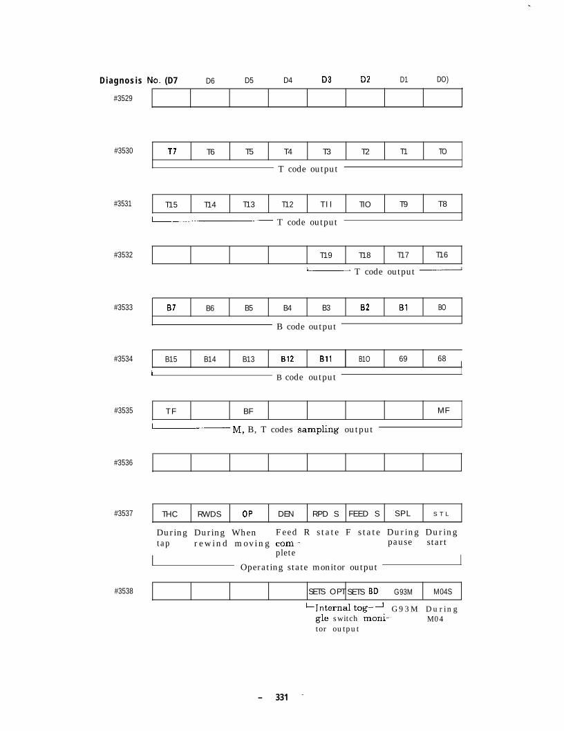
.
Diagnosis No. (D7 D6 D5 D4 D3 D2 D1 DO)
#3529
#3530 T7 T6 T5 T4 T3 T2 T1 TO
T code output
#3531 T15 T14 T13 T12 T l l TIO T9 T8
~ T code output
#3532 T19 T18 T17 T16
~ T code output ~
#3533 B7 B6 B5 B4 B3 B2 B1 BO
B code output
#3534 B15 B14 B13 B12 Bll B1O 69 68I
I B code outputI
#3535 T F BF MF
~ M, B, T codes ~ampling output
#3536
#3537 THC RWDS OP DEN RPD S FEED S S P L S T L
During During When Feed R state F state During Duringtap rewind moving com– pause start
plete
Operating state monitor output
#3538 SETS OPT SETS BD G93M M04S
‘Internal tog– ‘. G93M Duringgle switch monl– M04tor output
– 331 –

10.3 OUTPUT SIGNAL NC+ PLC (Cent’d )
Diagnosis No. (D7 D6 D5 D4 D3 D2 D1 DO)
#3539
#3540
#3541
#3542
#3543
#3544
#3545
#3546
#3547
#3548
#3549
TAP G84S G80SI
-1‘Canned cycle operatingstate mo;itor output
U07 U 06 U 0 5 u 04 u 03 u 02 Uol Uoo
Microprogram output signal
U015 U014 U013 U012 Uoll Uolo U09 U 08
~ Microprogram output signal
U023 U022 U021 U020 U019 UO18 U017 U016
Microprogram output signal
] U031 I U030 I U029 I U028 I U027 I U026 I U025 I U024 ]
~ Microprogram output signalI
Posx Uvx Ovx RGX MCBX Ocx ABSX
I X–axis IAMP alarm J
lo-pHx 10 IREFXl OF X I I II X–axis IAMP alarm
I
POSY U V Y O V Y R G Y MCBY OCY ABSY
I Y--axis IAMP alarmI
lo-pHY 10 IREFYl O F Y [ I I I
Posz Uvz Ovz RGZ MCBZ Ocz ABSZ
I Z--axis IAMP alarmI
O-PHZ OIREFZ OFZ OHZI Z–axis IAMP alarm I
– 3 3 2 –

X–axis to 5th axis servo axes control 1/3
Diagnosis No. (D7 D6 D5 D4 D3 D2 D1 DO)
#3610
#361 1
#3612
#3613
#3614
#3615
#3616
#3617
#3618
#3619
#3629
I I I I I I *OLX \ FUX I SRDXj
~ Servo unit monitor output ~
*(ILY I F U Y I SRDY
i Servo unit monitor output ~
1 *OLZ FUZ SRDZ
L Servo unit monitor output ~
*oL4 FU4 SRD4
~ Servo unit monitor output ~
*OL5 FU5 SRD5I
~ Servo unit monitor output ~
FUP5 FUP4 FUPZ FUPY FUPX
~ Followup monitor output ~
PSET5 PSET4 PSETZ PSETY PSETX
~ In–position state monitor output -
DTCH5S DTCH4S
L Output during -1
axis detachment
I AMLK5S AMLK4S AMLKZS AM LKYS AMLKXS
L Output during machine lock by axisJ
ABSER5 ABSER4 ABSERZ ABSERY ABSERX
L Absolute position detection error output d
– 3 3 3 –
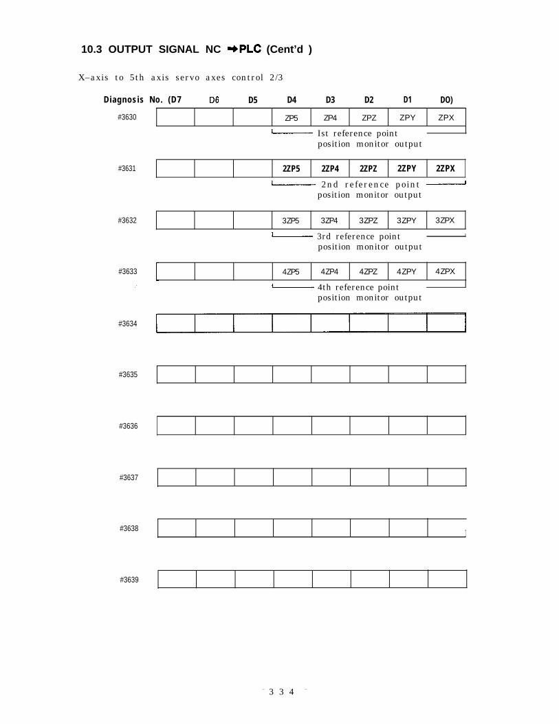
10.3 OUTPUT SIGNAL NC -bPLC (Cent’d )
X–axis to 5th axis servo axes control 2/3
Diagnosis No. (D7 D6 D5 D4 D3 D2 D1 DO)
#3630
#3631
#3632
#3633
/
#3634
#3635
#3636
#3637
#3638
#3639
ZP5 ZP4 ZPZ ZPY ZPX
~ Ist reference pointposition monitor output
2ZP5 2ZP4 2ZPZ 2ZPY 2ZPX
~ 2nd reference point ~position monitor output
3ZP5 3ZP4 3ZPZ 3ZPY 3ZPX
~ 3rd reference point I
position monitor output
1 4ZP5 4ZP4 4ZPZ 4ZPY 4ZPX
~ 4th reference pointposition monitor output
I
– 3 3 4 –

X–axis to 5th axis servo axes control 3/3
Diagnosis No. (D7
#3640~
#3641
#3642
#3643
#3644I
#3645
#3646
#3647
#3648
#3649
– 3 3 5 –

10.3 OUTPUT SIGNAL NC+ PLC (Cent’d )
Spindle control signal
Diagnosis No. (D7 D6 D5 D4 D3
#3650
#3651
#3652
#3653
#3654
#3655
#3656
#3657
#3658
D2” D1 DO)
I GR4S I GR3S I GR2S I GRIS I GRSS
I————— Gear range state output ~ OutputduringGRScontrol
GRCS G96S SINVA
output output outputduring during duringG R C G96 S bina–control control ry in–
version
SF 0s SLPS SIDXO SIDXA
S com- Spindle Spindle LSpindle index Jmand orien– posi– monitor outputsam– tation t i o npling loopoutput monitor
output
AXMODES C A X S
Axis Modecontrol changingmode
Pcs PBS PASI
~ PG signal monitor -
output
1 SD07 SD06 SD05 DS04 SD03 SD02 SDO1 SDOO
~ S specified binary output ~
SD015 SD014 SD013 SD012 SDO1l SDO1O SD09 SD08
~ S specified binary output J
SD023 SD022 SD021 SD020 SD019 SD018 SD017 SDO16
i S specified binary output 1
I SARM7 I SARM6 I SAR-M5 I SARM4 I SARM3 I SARM2 I SARM1 I SARMO I
~ Spindle speed monitor output ~
lsARM151sARM141 sARM131sARM121sARMll lSARMlOl sARM9 \ sARM8 I1 Spindle speed monitor output 1
– 336 –

Diagnosis No. (D7 D6 D5 D4 D3 D2 D1 DO)
#3659 SARM23 SARM22 SARM21 SARM20 SARM19 SARM18 SARM17 SARM16
~ Spindle speed monitor output ~
#3740 LD1-7 LD1-6 LD1-5 LDI-4 LD1-3 LD1-2 LD1-1 LD1-O
~ X-axis load data (L) ~
#3741 LD1-15 ~D1-14 LDI-13 LD1-12 LDI-11 LD1-10 LDI-9 LD1-8
~ X-axis load data (H) ~
#3742 LD2-7 LD2-6 LD2-5 LD2-4 LD2-3 LD2-2 LD2-1 LD2-O
~ Y-axis load data (L) ~
#3743 LD2-15 LD2-14 LD2-13 LD2-12 LD2-11 LD2-10 LD2-9 LD2-8
~ Y-axis load data (H) ~
#3744 LD3-7 LD3-6 LD3-5 LD3-4 LD3-3 LD3-2 LD3-I LD3-O
~ Z-axis load data (L) ~
#3745 LD3-15 LD3-14 LD3-13 LD3-12 LD3-11 LD3-10 LD3-9 LD3-8
~ Z-axis load data (H) ~
#3746 LD4-7 LD4-6 LD4-5 LD4-4 LD4-3 LD4-2 LD4-1 LD4-O
~ 4th axis load data (L)~
#3747 LD4-15 LD4-14 LD4-13 LD4-12 LD4-11 LD4-10 LD4-9 LD4-8
~ 4th axis load data (H)~
#3748 LD5-7 LD5-6 LD5-5 LD5-4 LD5-3 LD5-2 LD5-1 LD5-O
~ 5th axis load data (L)~
#3749 LD5-15 LD5-14 LD5-13 LD5-12 LD5-11 LD5-10 LD5-9 LD5-8
~ 5th axis load data (H)~
– 3 3 7 –

10.3 OUTPUT SIGNAL Nc +PLC (Cent’d )
Constant (D7 D6 D5 D4 D3 D2 D1 DO)
#3990[ I
#3991
#3992
#3993
#$994
#3995
#3996 o 0 0 0 0 0 0 0Constant
#3997 o 0 0 0 0 0 0 0I Constant (
#3998 o 0 0 0 0 0 0 0
Constant
#3999 o 0 0 0 0 0 0 1
I Constant t
– 338 –

YASNAC i80MCNC SYSTEM FOR MACHINING CENTERS
APPENDIX
TOKYO OFFICE Ohtemachl Bldg, l-6-l Ohtemachi, Chiyoda-ku, Tokyo, 100 JapanPhone (03)3284-9111 Telex YASKAWAJ33530 Fax (03)3264-9034SEOUL OFFICE 8th Floor Seoul Center Bldg,91-l, Sogong-Dong, Chung-ku, Seoul, Korea lOO-O7OPhone (02)776-7844 Fax (02)753-2639TAIPEI OFFICE Shen Hsiang Tang Sung Chiang Building 10 F146Sung Chiang Road, Taipei, TaiwanPhone (02) 563-0010, -7732 Fax (02)567-4677YASKAWA ELECTRIC AMERICA, INC.Chicago-Corporate Headquarters 2942 MacArthur Blvd. Northbrook, IL 60062-2028, U.SAPhone (708)291-2340 Fax (708)498-2430Chicago-Technical Center 3160 MacArthur Blvd. Northbrook, lL60062-1917, U.S.A.Phone (708)291-0411 Fax (708)291-1018MOTOMAN INC.805 Uberty Lane Wast Carrollton, OH 45449, U.S.A.Phone (513)847-6200 Fax (513)847-6277YASKAWA ELECTRIC EUROPE GmbHNiederhochstadter Strape 73, 61476 Kronberg-Oberhochstadt, GermanyPhone (06173 )~9380 Telex 415660 YA~ED Fax (06173)66421YASKAWA ELETRICO DO BRASIL COMERCIO LTDA.Rua Conde Do Pinha18-&, Andar Sala51 CEP01501-Sao Paulo-SP, BrasilPhone (Oil) 35-1911 Fax(Oll) 37-7375YASKAWA ELECTRIC (SINGAPORE) PTE. LTD.Head Office : CPF Bldg, 79 Robinson Road # 13-05, Singapore 0106, SINGAPOREPhone 221-7530 Telex (87) 24890 YASKAWARS Fax 224-5854Sewice Center: 221 Henderson Road, #07-20Henderson Building Singapore 0315, SingaporePhone 276-7407 Fax 276-7406YATEC ENGINEERING CORPORATIONShen Hsiang Tang Sung Chiang Building 10 F146Sung Chiang Road, Taipei, TaiwanPhone (02) 563-OO10 Fax (02)567-4677
YYASKAWA ELECTRIC CORPORATION
YASUAWA
TOE-CS43-11 .31 E~ ~qfd in Japan July 1994 90-3 IZ @