yanfeng gage standardsn. gage certification 14 o. third party certification 14 p. gage instructions...
TRANSCRIPT

Yanfeng Global Automotive Interiors Global Supplier Standards Manual
Chapter 2 Tooling & Equipment (December 6, 2017)
Uncontrolled if printed
Yanfeng Gage Standards
Yanfeng and Supplier Managed Gages
This manual is for the intended use of the employees and suppliers of Yanfeng, Inc. and is considered to be a PROPRIETARY DOCUMENT. Any distribution or sharing of this document is prohibited. All copies must be obtained from the Yanfeng Gage Engineer.

1
TABLE OF CONTENTS
Introduction 2
Scope 3
General Requirements 4
Safety and Ergonomic Requirements 5
Quotation Requirements 7
Gage Design Requirements 8 A. Concept Drawing 8 B. Gage Design 8
Gage Build Requirements 10 A. Bases 10 B. Tooling Balls / Tooling Holes 10 C. Risers and Stanchions 10 D. Details 10 E. Removable Details 11 F. Hinged Details 11 G. Locating Pins 11 H. Clamps 11 I. Scribe Lines / Tolerance Bands 11 J. SPC Indicators 12 K. Build Tolerances 12 L. Labeling 13 M. Corrosion Protection 14 N. Gage Certification 14 O. Third Party Certification 14 P. Gage Instructions 15 Q. Function Check 15 R. Measurement Systems Analysis – Gage R study 15 S. Measurement Systems Analysis – Gage R&R study 16 T. Shipping / Transportation 17 U. Preventive Maintenance Instructions 17 V. Gage Records 17 W. Specialty Gaging 18 X. Automated and Semi-Automated Gaging 18
Appendices 19 A. Appendix A – Documents 19 B. Appendix B – Diagrams 40 C. Appendix C – Standard Materials List 69 D. Appendix D – Revision Table 70 E. Appendix E – Reference List 72 F. Appendix F – Glossary of Terms 73

2
Go to Table of Contents
INTRODUCTION
TO OUR GAGE SUPPLIERS The intent of this manual is to define the Yanfeng Global Automotive Interiors requirements for gages and fixtures. It also goes beyond the simple design and build requirements and sets forth other requirements for our Gage / Fixture Suppliers. Since Yanfeng has many customers, it is important to understand that our manual is to be used as a guide in conjunction with our customers’ standards. The intent of this standard is to supersede any customer requirements that are more lenient but to utilize any customer requirements that are more demanding. We understand that all customer requirements are different, but we believe that by using this manual, there will be less confusion and more consistency in designing and building gages for Yanfeng. The intent of this manual IS NOT to dictate the process of HOW to build a gage but to GUIDE you in completing your task. While this manual sets forth certain minimum gage and procedural requirements, it is not intended to be absolute. It is both Yanfeng’s and the Gage Suppliers’ responsibility to continuously improve and to be objective in its approach to any gage program. Therefore, your independent analysis of these requirements and suggested changes or improvements are welcomed. We do ask, however, that any proposed deviation from this manual be approved by the Yanfeng Gage Engineer prior to its incorporation. Your responsibility in our TEAM is a large one. The quality, functionality, value and timeliness of these gages are a direct reflection of your company. You have to not only show the expertise in your field, but also provide invaluable assets like responsiveness, integrity, dependability and ingenuity. These assets are an EXPECTATION and will not be deviated from. Sincerely Doug Stewart Gage Engineer Yanfeng Global Automotive Interiors

3
Go to Table of Contents
SCOPE This Gage Standard applies to all of Yanfeng Global Automotive Interiors - North American and its Gage Suppliers. This Gage Standard establishes requirements for gages and fixtures that are used in conjunction with the inspection, measurement, and evaluation of the part. Such gages and fixtures are Attribute gages, SPC gages, CMM holding fixtures or any combination thereof. Generally, gages and fixtures are defined as: FIXTURE
• A device that is used to hold one or more parts while various operations are performed. For instance, a fixture is used to hold the part while an inspection is performed.
GAGE • An instrument that is used to measure the part. For instance, a gage is a fixture with an Attribute rail or SPC
indicator port attached to it. PLEASE NOTE: The terms fixture and gage are commonly referred to as the same piece of equipment. A fixture and a gage can be the same, but not always. If the measuring instrument is not attached to the holding device, then it is only a fixture [CMM holding fixture], whereas, if the measuring instrument is attached to the holding device [Attribute gage, SPC gage], it becomes a gage.
This Gage Standard does not establish requirements for jigs, assembly fixtures, milling fixtures, assembly nests, headliner tub fixtures, calipers, micrometers and the like. It does, however, provide instructions or guidelines that could be used with these types of equipment. Please note the following terms and their definitions as they are used in this document: Term Definition YF representative Yanfeng Global Automotive Interiors representative Gage Engineer Yanfeng Global Automotive Interiors Gage Engineer Supplier Gage Supplier

4
Go to Table of Contents
GENERAL REQUIREMENTS 1. The Supplier must quote in compliance with the Reliability and Maintainability requirements as stated on the Gage Request for Quote
or the form. If these requirements cannot be met, the Supplier must either “no quote” the job or obtain a written deviation from the YF representative.
2. Receipt of the hardcopy purchase order does not necessarily represent the start date of the work to be completed. The start date will be established when the purchase order number is sent via e-mail (or verbally) or the receipt of the CAD model or prints, whichever is later. The start date plus the quoted timing will establish the gage delivery date. All deviations from the delivery date must be communicated to the Yanfeng team in writing. Only circumstances fully outside of the Supplier's control will be considered as acceptable program delays.
3. All work that is started without a purchase order number and/or CAD model will be the Supplier’s responsibility, if the program is delayed or canceled.
4. The Supplier is responsible for the accuracy of all gages. Work resulting from the use of “out of calibration” equipment or defective processes will be the Supplier’s responsibility and must be corrected without cost to Yanfeng. This includes the equipment and processes for any sub-suppliers. Return to Gage Build Requirements – Section A. Gage Certification, item #1
5. If a gage was used to qualify a part or process and the it was found to be in error (i.e. built or certified with equipment that is out of calibration, a net surface is cut to the wrong side of material, etc.), the Supplier may be charged for prevailing layout cost, air freight part shipment charges, labor charges and/or other charges directly related to the discrepant gage. In addition, if a tool has been modified using a gage that was not dimensionally correct, the Supplier may be charged for the tool work to correct the part. Yanfeng will make every effort to ensure the gages are re-verified within the same parameters (temperature, humidity) as the Supplier. To ensure that equipment changes are not done hastily or needlessly, the YF representative must allow the Supplier to re-verify the gage before any changes are initiated. If there is a question or concern, the YF representative, the Supplier and the Gage Engineer will meet to resolve the issue. Return to Gage Build Requirements – Section A. Gage Certification, item #1.
6. The Supplier is responsible for part to gage clearance issues regardless of when parts are available. If the gage is shipped to Yanfeng prior to part availability, the return shipping cost will be Yanfeng responsibility.
7. All gages must be warranted against manufactures’ defects for the life of the program. Warranty items may consist of substandard materials, poor labeling or any items that may cause bodily injury. Any detail in need of repair or replacement due to operator error, poor maintenance, or overall neglect is not considered warranty items. If a warranty item is in question, it will be brought to the Gage Engineer’s attention and decided upon jointly, between the Gage Engineer, the YF representative, and the Supplier.
8. Throughout the life of the program, the Supplier may be requested to provide a cost breakdown for quoted and/or completed work. The Yanfeng Gage Cost Breakdown form must be used to supply this information.
9. No fixtures will be modified from the original design without the prior consent of the YF representative. 10. If a gage is to be used in a country other than the continental United States, all labeling and documentation must be in English and
the respective native language. The Gage Request for Quote will indicate whether or not international labeling and documentation is required. The YF representative will make the final determination of which specific labels or documents are to be translated. The YF representative will assist in the translations as required.
11. If Yanfeng provides or assists in the development of new or innovative devices or techniques, the Supplier may not disclose this information (verbal or tangible) to anyone outside of Yanfeng without the written permission of the Gage Engineer. This shall prevail for a period of three years after delivery of the gage. All trade secrets and/or patent rights are the property of Yanfeng.
12. A Supplier shall not share any photograph or video images of any Yanfeng gages with anyone outside of Yanfeng without the written permission of the Gage Engineer. All images are the property of Yanfeng.
Go to Glossary of Terms

5
Go to Table of Contents
SAFETY AND ERGONOMIC REQUIREMENTS 1. Every effort must be made to design and manufacture a gage or fixture that is operator friendly. Safety is top priority at Yanfeng and
it must be carried over into the equipment that is purchased. If an ergonomic issue is in question after a fixture is built then the YF representative and Supplier must determine the course of action and financial responsibility. If agreement cannot be made the Gage Engineer will arbitrate.
2. The entire gage must be free of any sharp edges and/or burrs, paying very close attention to the “operators area of movement.” 3. Attention must be given when purchasing or designing and building toggle clamps, hinge drops, and other movable details that can
pinch the operator. Clamps that are free of pinch points must be used whenever possible. 4. Toggle Clamps and hinged drops must have mechanisms installed that prevent free falling onto the operator (handle stops, toggle
clamp lockout, hinge drop lockout). This pertains not only in its built position but also if it will be rotated into a different orientation for inspection purposes.
5. Every effort must be taken to ensure that any removable detail does not exceed 40-lbs. In those circumstances the 40-lb. weight is exceeded, assist devices such as counter balances must be used. Also, considerations must be given to the ease of removal and assembly of these details. Hand cutouts, handles, forklift sleeves or eyebolts must be installed whenever possible.
6. The following weight restrictions apply: • Fixtures < 40 pounds must have two (2) lift handles installed. • Fixtures > 40 pounds but < 65 pounds must have four (4) lift handles installed. • Fixtures > 65 pounds but < 300 pounds must have a dedicated cart or table with casters. • Fixtures > 300 pounds must have eyebolts or forklift sleeves installed.
NOTE: The cart must be designed and fabricated with full and direct support on center of the fixture (center pillar with caster or leveling jack).
7. All lift handles attached to a gage should have a minimum grip length of 4”, a minimum grip width of 1”, and minimum hand access height of 1”.
8. The Supplier must make every effort to incorporate or allow for the following ergonomic information when designing and building a gage:
Operator (See anthropometric chart below)
Gage design Gage efficiency (Operator motion efficiency)
Arm reach Inspection tool placement Task / operation time
Work envelope Proper clearances Operator postures
Arm elevation Mechanisms are easily accessible Operator fatigue
Work forces Mechanisms are operated easily Eliminate unnecessary motions
Motion – bending / twisting Tools / mechanisms can be used by both right and left handed people Minimize operator reaches per cycle
Right hand vs. left hand Working height of gage is 41” Part location on the gage
Anthropometric Measurements
Body Dimension Range of Motion Low – High
Working (standing) elbow height 38 – 47
Maximum frequent arm elevation 50 – 62
Standing eye height 57 – 70
Optimal horizontal work envelope (measured from the center of rotation of the shoulder) 12 – 15
Functional non-extended horizontal reach (measured from the shoulder blade) 25 – 32
Range of Motion figures are in inches.

6
9. The Supplier must make every effort to design and build the gage in a manner that is “operator friendly”. Refer to the Ergonomic Repetition Benchmark Matrix, Ergonomic Force Benchmark Matrix, and the Ergonomic Posture Benchmark Matrix for further clarification. The Supplier may contact the Yanfeng Ergonomics team for clarification.
Go to Glossary of Terms

7
Go to Table of Contents
QUOTATION REQUIREMENTS 1. Each gage quotation must contain the following information:
• Yanfeng program name • Part description • Detailed description of the work to be accomplished. • Any deviations from the quotation. • Itemized cost
– Design – Build – Third Party Certification** – Gage R
• Quotation total cost • Itemized timing
– Design – Build (NOTE: Timing for internal Certification, Third Party Certification and Gage R must be included in
the gage build timing.)
** See Gage Build Requirements – Section B. Third Party Certification, Item #1 for Third Party Certification requirements. 2. The Supplier’s quote must reflect the use of the materials listed in the Standard Materials list. Reference Appendix C. Standard
Material List. 3. If a Supplier intends to use recycled components on the gage, it must be identified on the quote. If it is not noted, the gage must be
built using new components. 4. It is important that the Supplier understands the specific quote requirements at the time of quotation. Cost and timing must reflect
these requirements. Further, any assumptions and/or exceptions that affect cost and timing must be clearly identified on the quotation.
5. When a quotation requires flush and feeler details, sheet metal representations, or part surface representations, aluminum or fixture plank must be used. Overall gage weight and/or detail wear resistance are items to consider when determining which material to use.
6. If a part requires CMM dimensional inspection on the underside of the part, then the part must be held a minimum of nine (9) inches off the base, otherwise it may be held as close to the base as feasibly possible. Return to Gage Design Requirements – Gage Design, Item #9
7. The gage base size must be a minimum of four (4) inches larger on each side than the size of the part as held on the gage. The base type, MIC 6 tooling plate verses cast aluminum, will be determined by the gage size. For parts that require bases bigger than 400 in², a cast aluminum base will be required (a welded steel base may be used with the approval of the YF representative). All other parts will require a MIC 6 tooling plate base. MIC 6 tooling plate bases must be a minimum of one (1) inch thick. In some cases, due to part configuration and/or fixturing requirements, a cast aluminum base smaller than 400 in² may be required. It is the Supplier’s responsibility to ensure that the proper base size and type will be used. If the base is in question, the Supplier must contact the Gage Engineer or YF representative for clarification. Return to Gage Build Requirements – Section A. Bases, item #4
8. If a Supplier chooses to “no quote” a gage or gage program, a 24-hour (or less) response time is required. This includes refusal of a package that is sourced using the Gage Assumptions / Gage Cost Model form.
9. Yanfeng may use the Gage Assumptions / Gage Cost Model form to estimate and source plastic part gages. When this form is used, the Supplier is not required to provide a quote, unless directed by the YF representative. If a cost breakdown is required, the Supplier will breakdown the Gage Cost Model cost vs. the supplier’s quoted cost. The Gage Cost Model will not be used to estimate costs of engineering changes.
Go to Glossary of Terms

8
Go to Table of Contents
GAGE DESIGN REQUIREMENTS A. CONCEPT DRAWING
NOTE: The concept drawing/design will be required on an “as needed” basis as dictated by the YF representative.
1. The Concept drawing is to be drawn on an 8.5" x 11" sheet of paper. 2. The Concept drawing must show the “Gage Intent.” It should reflect the Geometric Dimensioning and Tolerancing (GDT) scheme
and any special requirements reviewed at the quotation meeting. It should show approximate base size, part orientation, location of datums, location and orientation of clamps, location of flush rails / feeler rails, and location of SPC ports. The concept must be labeled with the Yanfeng gage number and gage description.
3. The concept review and approval DOES NOT give the authority to order gage materials. As shown in the Gage Design Requirements – Section B. Gage Design, item #11, approval of the gage design authorizes the ordering of materials and components. If gage materials have been ordered prior to final design approval, and changes are made to the gage design that affect these materials, the material costs for the unusable stock will be absorbed by the Supplier.
Go to Table of Contents B. GAGE DESIGN 1. All gage designs produced for Yanfeng must be computer generated. All designs must be in IGES format, both wire frame and
surface data included. Whenever possible, the fixture must be designed using solid modeling software for proper interpretations during design signoffs.
2. The gage design is intended to be an accurate representation of the gage. It should reflect how the gage will be constructed and must include the basic information such as, base size and type, part orientation, location, size and orientation of all stanchions, details and clamps, size and location of datums, location of flush rails / feeler rails, and location of SPC ports. It must have all necessary section cuts to show detail and any required blow up sections. Also, all internally manufactured “one-of-a-kind” components need to be drawn and dimensioned on the design.
3. Datums that are located on or near parting lines, gates, ejector pins, welds or any similar features must be brought to the attention of the YF representative for correction.
4. All stock items should be commercially purchased whenever possible. 5. All designs must have an isometric view of the gage on the design. 6. All designs must list all parts (assemblies, subassemblies or versions) that can be verified on the gage. Part numbers that are
referenced must be the less finish part number(s) without color designation. 7. All designs will be drawn and dimensioned using the metric system (except Standard English stock sizes) unless otherwise specified
by the YF representative. 8. Each design must have three Tooling balls or two Tooling holes and a Surface Target with start coordinates labeled on the gage
base. If a gage is to be sub-based, these items must be on each base. 9. All datum surfaces and locators must be labeled on the design with the respective GDT datum callout. 10. When a slot or similar feature is used as a Regardless of Feature Size (RFS) 4-way locator, it must be so designed as to allow each
locating feature to move independently. 11. All Pins and Blocks used for part inspection (i.e. go/nogo pin, plug gage, virtual condition pin) must be labeled on the design with
their respective size as well as the calculation(s) used to obtain that size. 12. If the design reflects a coordinate system other than the automotive X, Y, Z system, then the design must be clearly identified with
the appropriate coordinate references (i.e. H, W, L). 13. If the part is to be positioned in a different coordinate system than the CAD model (tool die draw or workline verses body position),
the design must be labeled in a distinct manner with the appropriate rotation points and angles to move to and from the original system. Return to Gage Build Requirements – Section K. Labeling, item #3
14. The design must show the storage locations for removable details or interchangeable details, and loose components (SPC Indicator, GO-NOGO pins, Plug gages). Also, when loose details or components are needed, a general note for tethering of the details is required to be on the design. Return to Gage Build Requirements – Section E. Removable Details, item #1
15. The design must reflect the proper clearance for dimensional layout inspection. Reference Quotation Requirements – Item # 4. 16. The YF representative must approve the initial gage design and subsequent design changes. It is recommended that two reviews
take place – one at or about 50% completion and one at 100% completion. The design does not have to be signed at the 50% review, but must be for the 100% review. The YF representative and the Supplier must sign the final design. Other signatures may be required, as dictated by the customer design standards and/or the YF representative. It is the Supplier’s responsibility to notify the YF representative prior to completing the design to determine who is required to sign the final design.

9
17. Design approval gives the authority for the Supplier to order gage materials. If materials have been ordered prior to final design
approval and changes are made to the gage design that affect these materials, the material costs for the unusable stock will be absorbed by the Supplier. Return to Gage Design Requirements – Section A. Concept Drawing, item #3
18. All design changes must be recorded in a standard change column on the design. 19. All gage details must be confined within the boundaries of the base, including details that move (toggle clamps, hinge drops, etc.) 20. The approved (signed) design is the property of Yanfeng and will be stored at the Supplier. An electronic copy (and hard copy as
required by the YF representative) must be supplied with the gage each time the design is updated. Reference Gage Build Requirements – Section H. Records, Item #2.
21. Yanfeng will supply all CAD models in its native format (CATIA, UNIGRAPHICS, etc.). Every effort will be made to minimize the file size while ensuring all the critical data is supplied. All IGES translation errors or problems are the Supplier’s responsibility.
22. In the event that the customer requires a manual design, items 2 – 14 above and standard gage design practices apply. The original design must be drawn on Mylar and must be neat and legible.
23. Consideration for maximum CMM access must be given when designing the clamp type and location. Horizontal handle or bayonet type clamps should be used when CMM access is a priority.
Go to Glossary of Terms

10
Go to Table of Contents
GAGE BUILD REQUIREMENTS A. BASES 1. It is the Supplier’s responsibility to ensure that the base meets the flatness, parallelism and squareness tolerances as specified
below. The datum scheme for these base measurements is defined as the base bottom as it sits in the horizontal position.
º 0.10 A Per 300 mm2
º 0.20 A Not to exceed over entire base
· 0.10 A Between top and bottom surfaces
Ô 0.15 All machined edges
NOTE: All Tolerances specified are in millimeters. 2. All edges must be machined square and beveled. 3. The base must have the J-Corner identified. 4. All Tooling plate bases smaller than 200 in2 require four (4) jig feet, one at each corner. Bases between 200 in2 and 400 in2 require
five (5) jig feet, one at each corner and one in the center. Bases larger than 400 in2 a cast aluminum base is required. A welded steel base may be used with the approval of the YF representative. Reference Quotation Requirements – Item # 5.
5. Tooling plate bases must be a minimum of 1” thick. 6. Cast aluminum, welded aluminum or steel bases must be stress relieved. 7. All bases must be of uniform thickness. It is the Supplier’s responsibility to inspect the base for uniformity before construction. If the
gage is constructed and the base is found to be varying in thickness, the base will have to be replaced and reconstructed at the expense of the Supplier.
Go to Table of Contents B. TOOLING BALLS / TOOLING HOLES 1. Three (3) Tooling balls or Tooling holes must be located and identified with the start coordinates on the base of the gage. These
features will be used to establish the origin of the fixture for certification and part layout. Reference Gage Build Requirements – Section D. Details, Item #11, for tooling ball requirements as single point net representations (datum target).
2. Tooling ball size will be .500 inch. Tooling hole size will be a minimum of 10 millimeters. 3. Each Tooling ball must have a protective cover. The cover must not interfere with the start coordinate labels. Go to Table of Contents C. RISERS and STANCHIONS 1. The risers and stanchions must be attached to the base securely with a minimum of two (2) dowels and two (2) cap screws unless
specified in the design as a removable detail. Reference Gage Build Requirements – Section E. Removable Details. 2. Risers and stanchions may be relieved or cut away in certain areas to gain access to the part for dimensional inspection. It is the
Supplier’s responsibility to ensure the area(s) that are removed do not affect the integrity or stability of the gage. Go to Table of Contents D. DETAILS 1. All details must be attached to the base securely with dowels and cap screws. It is the Supplier’s responsibility to ensure that the
correct quantities of dowel and cap screws are used. If the quantity is substandard, the Supplier must fix or replace the detail without costs to Yanfeng. Reference GAGE BUILD REQUIREMENTS – Section E. Removable Details for details that are to be built as removable.
2. Details shall not be shimmed during construction. 3. Details used as net surfaces must be made of steel. Steel plates located on aluminum details may be used. 4. Flush rails, feeler rails and sheet metal representations must be constructed of aluminum or fixture plank. Fixture plank must be
sectioned into details no larger than 400 mm in length each. 5. A 6 mm gap distance is to be used, unless otherwise specified by the YF representative customer gage build standards. 6. All net details that net around the area of a hole or cutout in the part must have CMM probe clearances cut into the detail. These
clearances must be a minimum of five (5) mm deep and two (2) mm bigger than the part feature. 7. All loose details (Plug gages, Go/NoGo pins) must be tethered to the gage using chain, Car-Lane cable, or retractable spring-loaded

11
cases with cable lockouts. These chains or cables may be removed if the detail is to be used when the part is scanned. 8. All noncircular plug gages must be keyed for orientation. 9. Unless otherwise specified by the customer, a plug gage located in a bushing and clamped on top will be the method to represent a
screw or fastener pin. 10. When a single point datum target is required, a tooling ball must be used. The associated clamp must be adjusted to not deform the
part. Return to Gage Build Requirements – Section B. Tooling Balls – Item #1 11. Each feeler rail must have an associated go/nogo feeler pin that reflects the proper tolerance. Go to Table of Contents E. REMOVABLE DETAILS 1. All removable details must use hardened bushings and bullet nose dowels. The bushings must be in the detail and the dowels must
be in the mating component. Reference Design Requirements – Section B. Gage Design, item #14. 2. When there are similar removable details used on the same gage, the details must have a unique locating scheme for each. Each
detail and storage location must be clearly labeled or color-coded. Reference Gage Build Requirements – Section C. Risers and Stanchions – Item #1 Reference Gage Build Requirements – Section D. Details – Item #1
Go to Table of Contents F. HINGED DETAILS 1. All hinge drop details must be counterbalanced or have a lock out mechanism installed. This also pertains if the gage will be tipped
90° to inspect the part. 2. All hinge drop details must have rubber stops installed to prevent damage. Go to Table of Contents G. LOCATING PINS 1. All locating pins must be tapered and spring-loaded (RFS pin). The Gage Engineer or YF representative must approve all other pins
(MMC pin, LMC pin). 2. All tapered RFS pins must locate the part approximately at the mid point of the taper. 3. All locating pins must be made of hardened steel. 4. If a locating pin must be locked out to load the part, the lockout mechanism must be positive. For instance, if a detail has an “L”
shaped cut to lockout the locating pin, the cut must have enough lead in to disengage the locating pin and hold it out of position. 5. The locating pin spring pressure must be strong enough to locate the part without distortion when clamped. 6. Spring loaded locating pins must move freely in all directions except the locating direction using graphite lubricant. Go to Table of Contents H. CLAMPS 1. All clamps must have a clamp direction of 90° to the part surface. 2. Clamps that are spring loaded must have a positive lockout mechanism. 3. When clamping over a hole, the clamp foot must be cut to allow access to the hole. 4. When engaging a clamp, it must not interfere with the part or any other detail(s) on the gage. 5. Clamp pressure must be the minimum required to locate the part, but stronger than the opposing spring-loaded features. 6. All clamp pressure feet must be mar-proof. Examples are rubber, neoprene or nylon. If metal clamp feet are required, they must be
free of burrs and sharp edges and have a mar-proof coating. Go to Table of Contents I. SCRIBE LINES / TOLERANCE BANDS 1. All scribe lines and tolerance bands must be scribed or milled into the surface. Painted lines on the surface are not acceptable. 2. All scribe lines and tolerance bands must be identified with a distinct color to ensure good visibility for measurement. If a nominal
line is included in the tolerance band, the nominal line must be contrasting color within the tolerance band. 3. Every effort must be made to minimize or eliminate the effect of the parallax error. 4. As required by the Customer or YF representative, gage bases may have bodylines scribed on them. It is recommended that the
bodylines are scribed every 100 mm for smaller fixtures and 200 mm for larger fixtures. These bodylines must be labeled with the appropriate body coordinate and left hand (-) or right hand (+) signification.
12
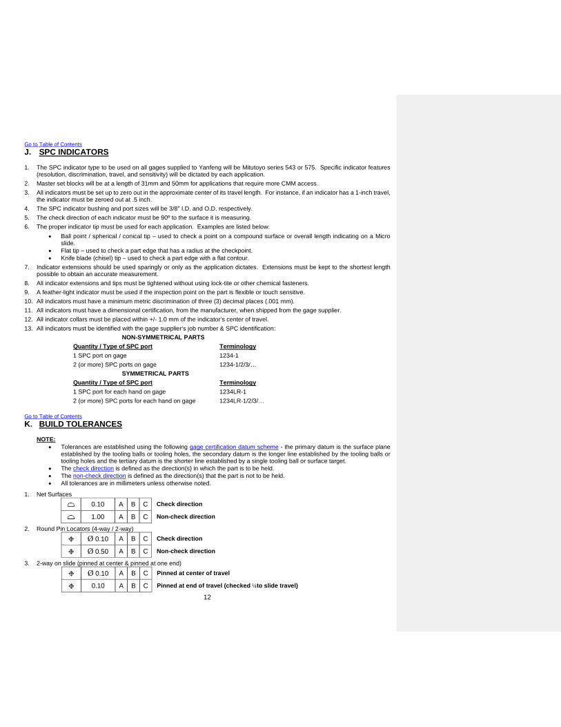
Go to Table of Contents J. SPC INDICATORS 1. The SPC indicator type to be used on all gages supplied to Yanfeng will be Mitutoyo series 543 or 575. Specific indicator features
(resolution, discrimination, travel, and sensitivity) will be dictated by each application. 2. Master set blocks will be at a length of 31mm and 50mm for applications that require more CMM access. 3. All indicators must be set up to zero out in the approximate center of its travel length. For instance, if an indicator has a 1-inch travel,
the indicator must be zeroed out at .5 inch. 4. The SPC indicator bushing and port sizes will be 3/8” I.D. and O.D. respectively. 5. The check direction of each indicator must be 90º to the surface it is measuring. 6. The proper indicator tip must be used for each application. Examples are listed below:
• Ball point / spherical / conical tip – used to check a point on a compound surface or overall length indicating on a Micro slide.
• Flat tip – used to check a part edge that has a radius at the checkpoint. • Knife blade (chisel) tip – used to check a part edge with a flat contour.
7. Indicator extensions should be used sparingly or only as the application dictates. Extensions must be kept to the shortest length possible to obtain an accurate measurement.
8. All indicator extensions and tips must be tightened without using lock-tite or other chemical fasteners. 9. A feather-light indicator must be used if the inspection point on the part is flexible or touch sensitive. 10. All indicators must have a minimum metric discrimination of three (3) decimal places (.001 mm). 11. All indicators must have a dimensional certification, from the manufacturer, when shipped from the gage supplier. 12. All indicator collars must be placed within +/- 1.0 mm of the indicator’s center of travel. 13. All indicators must be identified with the gage supplier’s job number & SPC identification:
NON-SYMMETRICAL PARTS Quantity / Type of SPC port Terminology 1 SPC port on gage 1234-1 2 (or more) SPC ports on gage 1234-1/2/3/… SYMMETRICAL PARTS Quantity / Type of SPC port Terminology 1 SPC port for each hand on gage 1234LR-1 2 (or more) SPC ports for each hand on gage 1234LR-1/2/3/…
Go to Table of Contents K. BUILD TOLERANCES
NOTE: • Tolerances are established using the following gage certification datum scheme - the primary datum is the surface plane
established by the tooling balls or tooling holes, the secondary datum is the longer line established by the tooling balls or tooling holes and the tertiary datum is the shorter line established by a single tooling ball or surface target.
• The check direction is defined as the direction(s) in which the part is to be held. • The non-check direction is defined as the direction(s) that the part is not to be held. • All tolerances are in millimeters unless otherwise noted.
1. Net Surfaces
0.10 A B C Check direction
1.00 A B C Non-check direction
2. Round Pin Locators (4-way / 2-way)
Ø 0.10 A B C Check direction
Ø 0.50 A B C Non-check direction
3. 2-way on slide (pinned at center & pinned at one end)
Ø 0.10 A B C Pinned at center of travel
0.10 A B C Pinned at end of travel (checked ¼to slide travel)

13
4. All other Locators
0.10 A B C Check direction
0.50 A B C Non-check direction
5. Attribute rail – flush and/or feeler [vector check]
0.40 A B C
6. Attribute rail – flush and/or feeler [shank check]
0.40 A B C
7. Sheet metal representation
0.30 A B C
8. SPC port location
0.20 A B C Check direction
Ø 0.50 A B C Non-check direction
9. Scribe lines
0.60 A B C
10. Sight checks (painted)
1.00 A B C
11. Slides
0.10 A B C Entire travel
12. Check pin location (MMC, LMC or VC pin)
Ø 0.15 A B C Check direction
13. Go Pin size
+0.00 / -0.02
14. Nogo Pin size
+0.02 / -0.00
Go to Table of Contents L. LABELING 1. All labeling on the gage must be legible and descriptive. The labeling must be placed in such a manner that it is readable when the
part is on the fixture. Labels may be engraved, printed or stamped. If tags are used, they must be permanently attached to the gage. 2. The following detail types must be labeled on the gage:
• All datums (net surfaces and locators) • Clamp sequence • Flush rail location and offset measurement • Feeler rail location and offset measurement • Go/NoGo pin sizes • Indicator port reference number • Master set block offset measurement • Body line references (appropriate customer references – XYZ or LWH) • Specific measurement locations
3. Tooling balls or tooling holes on the base must be clearly labeled with their respective start coordinates. If there are more than three (3) tooling balls or tooling holes on the base, the three (3) that are used to certify the fixture must be labeled with the word “Origin” next to the coordinate. Coordinates will be assumed to be in body position, but if they are in work line or other, they must be clearly identified with the coordinate system used. Reference Gage Design Requirements, Section B. Gage Design, item #7.
4. Each gage must have a Supplier Identification tag permanently attached to it. Each tag must be labeled with the following information:

14
A. Supplier name, address and phone number B. Supplier job number C. Customer D. Yanfeng Gage Number (84xxxx) E. Gage Description F. Part Revision Level G. Certification date H. Program name(s) and part name(s)
As Required I. Third party source name, address, phone number and certification date J. List of part numbers and names (if gage checks multiple parts)
5. Gage instructions must be affixed to each gage. Reference Gage Build Requirements - Section P. Gage Instructions, item #2. 6. All indicators must be identified with the gage supplier’s job number & SPC identification:
NON-SYMMETRICAL PARTS Quantity / Type of SPC port Terminology 1 SPC port on gage 1234-1 2 (or more) SPC ports on gage 1234-1/2/3/… SYMMETRICAL PARTS Quantity / Type of SPC port Terminology 1 SPC port for each hand on gage 1234LR-1 2 (or more) SPC ports for each hand on gage 1234LR-1/2/3/…
Go to Table of Contents M. CORROSION PROTECTION 1. All steel components must be black oxided. 2. All non-mating surfaces must be painted with the customer-required color. If a color is not specified, blue is to be used. Go to Table of Contents N. GAGE CERTIFICATION 1. It is the Supplier’s responsibility to ensure that the cutter path and certification data are correct. See General Requirements – item
#4 & General Requirements – item #5 for clarification. The accuracy of the gage must be verified using a certified CMM (traceable to a national standard). One of a kind details, like step blocks or thickness feelers, may be certified with traceable hand held equipment (micrometers, calipers). Purchased inspection details and devices (gage pins, scales, indicators) may be certified by including the certification report from the manufacturer. If a report is not sent, the detail must be certified using appropriate means.
2. The Supplier Internal Certification must use a vector check for all net surfaces, sheet metal representations and compound surfaces. A “set two, check one” check may be used on details that represent a one-direction check like a net point, flush rail, or feeler rail. SPC bushing locations must be verified and reported in the check direction but only verified in the non-check direction. Pin size and location and hole size and location must be verified and reported.
3. The number of certification masters developed for each detail is dependent on the size and complexity of the detail. It is the Supplier’s responsibility to develop a sufficient amount of points to demonstrate that the gage is dimensionally correct. As an example, on a typical 25 mm x 25 mm net block, it is recommended that a minimum of five (5) masters be used. There must be enough masters to evaluate any single or combination of elements of size, location, orientation and profile.
4. All gage certifications must include a “road map” of the certification points. 5. All two way locators on a slide, must be certified in the center and at one end of the slide’s full travel. Each location must be pinned
(for certification) and clearly identified on the gage certification. Go to Table of Contents O. THIRD PARTY CERTIFICATION 1. A Third Party Certification is required on all gages that are manufactured by a Supplier who’s certification department IS NOT
accredited to a nationally recognized laboratory or inspection standard (i.e. ISO Guide 25 or ISO Guide 17025). This accreditation must be performed by a duly recognized accreditation body (American Association for Laboratory Accreditation – A2LA or equivalent). Certification to the QS9000 or TE9000 standard DOES NOT supersede this requirement; it is in conjunction with it. Refer to the AIAG QS9000 manual paragraph 4.11.2.b.1 for clarification. This Third Party certification must be performed one of two ways:
• The third party source verifies the certification masters against the CAD model and inspects the gage at the third party facility.
• The third party source develops new certification masters and inspects the gage at the third party facility.

15
Return to Quotation Requirements – item #1 2. It is the Supplier’s responsibility to ensure the accuracy and on time delivery of the Third Party Certification. 3. If the Third Party Certification is found to be discrepant, it is the Supplier’s responsibility to correct it without cost to Yanfeng, up to
and including the internal and Third Party recertification. Go to Table of Contents P. GAGE INSTRUCTIONS 1. All gages must have gage instructions attached to the gage. Also, an electronic copy must be supplied on a CD upon delivery of the
gage. Reference Gage Build Requirements – Section H. - Gage Records, item #2. 2. The gage instructions must be detailed and understandable with references to the gage clearly labeled. They must identify the gage
preparation, loading, clamping, inspection and unloading of the part. The instructions must include all part configurations. They must include a picture of the gage with the appropriate references identified (locators, net surfaces, check points, etc). Return to Gage Build Requirements – Section K. – Labeling, Item #5
Go to Table of Contents Q. FUNCTION CHECK 1. A function check must be performed prior to delivery of the gage. The Supplier may utilize their own completion checklist, but it must
include all the items listed on the gage completion checklist in the appendix. The function check of the gages must consist of the following steps as a minimum:
A. Evaluate the gage against the gage design. B. Function all components on the gage. C. Using the gage instructions, load the part on the gage. D. Identify and remove all interferences. E. Document the results. F. Correct any discrepancies.
2. It is the Supplier’s responsibility to request parts for the function check. If the gage is to be delivered prior to part availability, all items above must be performed, with the exception of items C and D. When parts become available, it is the responsibility of the Supplier to complete the function check.
Go to Table of Contents R. MEASUREMENT SYSTEMS ANALYSIS – Gage R study 1. A Gage Repeatability (Gage R) study must be performed prior to final buyoff and/or delivery of the gage. For engineering changes,
refer to step #6. 2. The inspection points for the Gage R study must be approved by the Yanfeng Gage Engineer or YF representative prior to completing
the study. 3. The Gage R studies must conform to the following:
CMM Holding Fixture or Attribute Gage a. A set of nine (9) Gage R studies must be performed on the CMM; three (3) studies for each set of three (3) points
in each body direction – 3 pts FA, 3 pts CC, and 3 pts FA. CMM/SPC Gage
a. A set of nine (9) Gage R studies must be performed on the CMM; three (3) studies for each set of three (3) points in each body direction – 3 pts FA, 3 pts CC, and 3 pts FA.
b. Each SPC “point on part” coordinate must be performed on the CMM. c. Each SPC port must have a study performed by manually inserting the indicator into the port.
Phase 1 / Phase 2 Design and Build Gage a. For Phase 1, follow CMM Holding Fixture, item a. b. For Phase 2, follow CMM/SPC Gage, items b & c.
4. The Gage R study will use one (1) operator loading one (1) part ten (10) times.
4.1. The Gage R studies must be performed using the CMM as well as manually inserting the indicator(s) into the SPC port(s) as identified in item 4.
4.1.1. CMM HOLDING FIXTURE or ATTIBUTE GAGE A. Obtain one (1) part from the Yanfeng representative. B. Using the CAD model, obtain nine (9) body coordinate points, three in each direction (X, Y, and Z) to show the most
variation in each axis. NOTE: The chosen points must be approved by the Yanfeng Gage Engineer or representative. It is preferred that each point be on an edge to allow the CMM to “shank” check the part, checking only in the primary check direction.
C. Using the gage instructions, load the part on the gage. D. Using a CMM, measure each of the body coordinates. Record the deviation from the master check direction for each

16
coordinate. E. Unload the part. F. Repeat steps C–E until the ten (10) trials are complete. G. Input data into the Gage R form, calculate and analyze the result (MiniTab Type 1 Gage Study is the preferred
method). H. If the study is found to be unacceptable, the Yanfeng Gage Engineer and/or representative and the Supplier must
jointly determine the improvements needed to obtain an acceptable result. 4.1.2. SPC GAGE
A. Obtain one (1) part from the Yanfeng representative. B. Using the gage instructions, load the part on the gage. C. Zero indicator in Master Block. D. Insert indicator into each SPC port and record the measurement(s). E. Unload the part. F. Repeat until all readings, at each SPC location, have been obtained. G. Input data into Gage R form, calculate and analyze the result (MiniTab Type 1 Gage Study is the preferred method). H. If study is found to be unacceptable, the Yanfeng Gage Engineer and/or representative and the Supplier must jointly
determine the improvements needed to obtain an acceptable result. 4.2. Acceptance criteria for the Gage R / Type I gage study will be as follows:
>20% Will not be accepted without approval from the YANFENG representative.
10% - 20% Borderline acceptable. Must investigate cost and timing impact to improve measurement system. Yanfeng representative must approve plan.
0% - 10% Acceptable.
5. The Attribute study will be performed using the CMM Fixture method. Refer to item 3 and 4.1.1.
6. If an engineering change is completed that affects the locating or measurement scheme of the gage, the Measurement Systems Analysis process must be re-verified. If the engineering change is in question, it is the Suppliers’ responsibility to contact the Yanfeng representative for clarification.
7. Completion of the Gage R&R study does not waive the Supplier’s responsibility to repair or adjust the gage (at no cost to Yanfeng) if the Gage R&R study or Attribute study, required for PPAP, is unacceptable. The Yanfeng representative and the Supplier must jointly determine the improvements needed to obtain an acceptable result.
Go to Table of Contents S. MEASUREMENT SYSTEMS ANALYSIS – Gage R&R study 1. A Gage Repeatability and Reproducibility (Gage R&R) study must be performed prior to final buyoff and/or delivery of the gage. For
engineering changes, refer to step #7. 2. Yanfeng will supply a minimum of one (1) operator for this study. The Gage Supplier must obtain approval prior to running the study
without YF representation. 3. The inspection points for the Gage R&R study must be approved by the Yanfeng Gage Engineer or YF representative prior to
completing the study. It is preferred to use the same points from the Gage R study. 4. The Gage R&R studies must conform to the following:
CMM Holding Fixture or Attribute Gage b. A set of nine (9) Gage R studies must be performed on the CMM; three (3) studies for each set of three (3) points
in each body direction – 3 pts FA, 3 pts CC, and 3 pts FA. CMM/SPC Gage
a. A set of nine (9) Gage R&R studies must be performed on the CMM; three (3) studies for each set of three (3) points in each body direction – 3 pts FA, 3 pts CC, and 3 pts FA.
b. Each SPC “point on part” coordinate must be performed on the CMM. c. Each SPC port must have a study performed by manually inserting the indicator into the port.
Phase 1 / Phase 2 Design and Build Gage a. For Phase 1, follow CMM Holding Fixture, item a. b. For Phase 2, follow CMM/SPC Gage, items b & c.
5. The Gage R&R study will use three (3) operators loading ten (10) parts three (3) times each.
5.1. The Gage R&R studies must be performed using the CMM as well as manually inserting the indicator(s) onto the SPC port(s) as identified in item 4.
5.1.1. CMM HOLDING FIXTURE or ATTRIBUTE GAGE I. Obtain ten (10) parts from the Yanfeng representative. J. Using the CAD model, obtain nine (9) body coordinate points, three in each direction (X, Y, and Z) to show the most
variation in each axis. NOTE: The chosen points must be approved by the Yanfeng Gage Engineer or representative. It is preferred that each point be on an edge to allow the CMM to “shank” check the part, checking only in the primary check direction.
17
K. Using the gage instructions, load the part on the gage. L. Using a CMM, measure each of the body coordinates. Record the deviation from the master check direction for each
coordinate. M. Unload the part. N. Repeat steps C–E until the ten (10) trials are complete. O. Input data into the Gage R&R form, calculate and analyze the result (MiniTab Type 2 Gage Study is the preferred
method). P. If the study is found to be unacceptable, the Yanfeng Gage Engineer and/or representative and the Supplier must
jointly determine the improvements needed to obtain an acceptable result. 5.1.2. SPC GAGE
I. Obtain ten (10) parts from the Yanfeng representative. J. Using the gage instructions, load the part on the gage. K. Zero indicator in Master Block. L. Insert indicator into each SPC port and record the measurement(s). M. Unload the part. N. Repeat until all the readings, at each SPC location, have been obtained. O. Input data into Gage R form, calculate and analyze the result (MiniTab Type 2 Gage Study is the preferred method). P. If study is found to be unacceptable, the Yanfeng Gage Engineer and/or representative and the Supplier must jointly
determine the improvements needed to obtain an acceptable result. 5.2. Acceptance criteria for the Gage R / Type I gage study will be as follows:
>20% Will not be accepted without approval from the YANFENG representative.
10% - 20% Borderline acceptable. Must investigate cost and timing impact to improve measurement system. Yanfeng representative must approve plan.
0% - 10% Acceptable.
6. The Attribute study will be performed using the CMM Fixture method. Refer to item 4 and 5.1.1.
7. If an engineering change is completed that affects the locating or measurement scheme of the gage, the Measurement Systems Analysis process must be re-verified. If the engineering change is in question, it is the Suppliers’ responsibility to contact the Yanfeng representative for clarification.
8. Completion of the Gage R&R study does not waive the Supplier’s responsibility to repair or adjust the gage (at no cost to Yanfeng) if the Gage R&R study or Attribute study, required for PPAP, is unacceptable. The Yanfeng representative and the Supplier must jointly determine the improvements needed to obtain an acceptable result.
Go to Table of Contents T. SHIPPING / TRANSPORTATION 1. All gages must be completely protected from the elements when being shipped. 2. All gages must be secured when shipped. 3. Yanfeng will accept full responsibility of the gage when it is delivered and unloaded at Yanfeng receiving location. Go to Table of Contents U. PREVENTIVE MAINTENANCE INSTRUCTIONS 1. All gages must have Preventive Maintenance instructions supplied electronically on the CD upon delivery. 2. The Preventive Maintenance instructions must be detailed and understandable with references to the gage clearly labeled. They
must identify the maintenance instructions, recommended frequency of maintenance, recommended chemicals / solutions to use for maintenance and long-term storage preparation instructions. NOTE: If the chemicals / solutions cannot be purchased “over the counter”, then a hardcopy of the MSDS sheet must be included with the gage upon delivery.
Go to Table of Contents V. RECORDS 1. The Supplier is responsible to provide an itemized Gage Timing chart for each gage from initial kickoff to delivery on a periodic basis.
The report will be due every week but may be modified by the YF representative. Delays in program timing must be reported immediately, first verbally, then on the hardcopy timeline. For gages with total timing of less than three (3) weeks, no timeline is required.
2. The Supplier is responsible to provide two (2) electronic copies of the latest documents and data on a Compact Disk each time the gage is modified*. One copy will be attached to the gage and the other will be delivered to the YF representative. This disk must contain the following:
• Native CAD model

18
• Gage Design • Gage Certification • Gage R and/or Attribute study or studies • Gage Instructions • Gage Preventive Maintenance Instructions • Digital picture of the gage • Any other pertinent documents as required • Final gage timeline - OPTIONAL • Final gage checklist - OPTIONAL
∗ Modified is defined as any change to the fixture or its documents due to a Yanfeng or OEM directed change, repair, correction, etc. All modifications do NOT necessarily constitute a YF representative level change.
Return to Gage Design Requirements – Section B. Gage Design, Item #21 Return to Gage Build Requirements – Section C. Gage Instructions, Item #2 3. The CD jacket must be labeled with the Supplier name, Supplier job number, Yanfeng Tool Number, Gage Description, and revision
level. 4. All documents that require signed approval will be in original hard copy format and kept at the Supplier. Go to Table of Contents W. SPECIALTY GAGING
NOTE: Specialty Gaging is defined as any fixture or gage that employs the use of non-contact or technologically advanced devices used in place of more commonly used analog devices. Examples may include Lasers probes, Vision systems, or Magnetic systems.
1. The Supplier is responsible to prove-out and validate Specialty Gaging using the same methods as a fixture or gage as defined in
this standard. In addition, the Supplier is responsible to verify all software applications and/or written code provided with the gage. This verification is to be performed by testing the input and output relationships and results with a minimum of 3 replications on 10 different parts. This verification study must be documented and supplied with the gage.
2. Specialty gages must meet the YF Special Equipment General Specifications (SEGS) and Special Equipment Safety Specifications (SESS) as well as any applicable industry standards that may not be covered in the SESS and SEGS documents. If aspects of these manuals are in question, contact the YF representative or Capital Equipment Buyer for clarification.
Go to Table of Contents X. AUTOMATED and SEMI-AUTOMATED GAGING
NOTE: Automated Gaging is defined as piece of equipment that is used to assess the acceptability of the part without operator intervention, except for loading and unloading of the part. Semi-Automated Gaging is defined as a piece of equipment that is used to assist the operator in loading, clamping, measurement and/or unloading of the part. Examples for both types of gages may include pneumatic equipment or electronic equipment.
1. Prior to design and build of any Automated Gaging, the YF Representative must complete an Equipment Specification sheet. This
sheet will be used in place of the Gage Request for Quote or Gage Assumptions / Cost Model sheet. The Supplier is responsible to meet all requirements of the Equipment Specification.
2. The Supplier is responsible to prove-out and validate Automated and Semi-Automated Gaging using the same methods as a fixture or gage as defined in this standard. In addition, the Supplier is responsible to verify all software applications and/or written code provided with the gage. This verification is to be performed by testing the input and output relationships and results with a minimum of 3 replications on 10 different parts. This verification study must be documented and supplied with the gage.
3. Automated and Semi-Automated gages must meet the YF Special Equipment General Specifications (SEGS) and Special Equipment Safety Specifications (SESS) as well as any applicable industry standards that may not be covered in the SESS and SEGS documents. If the Supplier is in need of a copy of these manuals or if aspects of these manuals are in question, contact the YF representative or Capital Equipment Buyer for clarification.
4. The Supplier is responsible for dry cycling the Automated and Semi-Automated gaging. This dry cycle will consist of a continuous 20 hours of operation or as defined by the YF representative. The dry cycle results must be documented and supplied with the gage.
Go to Glossary of Terms

19
Go to Table of Contents
APPENDIX A – Documents DESCRIPTION APPENDIX # PAGE # Supplier Internal Certification A1 20
Third Party Certification A2 21
Gage Repeatability Study A3 22
Gage Completion Check List A4 23
Supplier Quotation A5 24
Gage Concept Drawing A6 25
Supplier Identification Tag A7 26
Gage Request for Quote A8 27
Gage Instructions A9 29
Gage Repeatability Study Coordinates A10 30
Gage Cost Breakdown A11 31
Gage Preventive Maintenance Instruction A12 32
Attribute Study A13 33
Gage Timing Chart A14 34
Check Pin and Check Block Calculation A15 35
Ergonomic Repetition Benchmarks matrix A16 36
Ergonomic Force Benchmarks matrix A17 37
Ergonomic Posture Benchmarks matrix A18 38

20
APPENDIX A1. Supplier Internal Certification Return to Gage Build Requirements, Section A. Gage Certification, Item #2. Go to Appendix List Go to Table of Contents
ABC Corporation 123 West 12th Street Somewhere MI 99998 ABC Job#: 1290A
Customer: Yangfeng Automotive Interiors Date Chkd: 04/Mar/00Part Name: GMT236 Overhead Console Chkd By: D. P.
Part Number: 9999998 File: 1290
START COORDINATESX = 3820.000 Y = -580.000 Z = 350.000
Detail No. X Master X Check X Diff Y Master Y Check Y Diff Z Master Z Check Z Diff. Vec. Dev. Chk Type Ln # Pt # Dim. Net Surface - Datum A1
1 2691.010 2690.981 -0.029 -827.998 -827.996 0.002 770.456 770.512 0.056 -0.063 Surf Rd 1 11 2691.010 2690.989 -0.021 -826.552 -826.497 0.055 794.329 794.346 0.017 0.061 Surf Rd 1 21 2702.691 2702.777 0.086 -827.116 -827.108 0.008 783.204 783.202 -0.002 -0.086 Surf Rd 1 31 2713.000 2712.996 -0.004 -827.788 -827.801 -0.013 770.456 770.499 0.043 0.045 Surf Rd 1 41 2713.000 2713.026 0.026 -827.998 -827.996 0.002 794.329 794.361 0.032 0.041 Surf Rd 1 5
Net Surface - Datum A22 3030.000 3030.001 0.001 -827.351 -827.359 -0.008 769.233 769.303 0.070 -0.070 Surf Rd 1 62 3030.000 3029.910 -0.090 -827.265 -827.259 0.006 749.962 749.976 0.014 0.091 Surf Rd 1 72 3042.000 3042.019 0.019 -827.279 -827.261 0.018 758.999 758.999 0.000 -0.026 Surf Rd 1 82 3055.000 3055.003 0.003 -827.198 -827.189 0.009 769.233 769.237 0.004 0.010 Surf Rd 1 92 3055.000 3054.995 -0.005 -827.000 -826.989 0.011 749.922 749.919 -0.003 0.012 Surf Rd 1 10
Net Surface - Datum A33 3262.000 3261.999 -0.001 -858.205 -858.199 0.006 920.000 919.999 -0.001 0.006 Surf Rd 1 113 3262.000 3262.000 0.000 -859.191 -859.215 -0.024 897.999 898.002 0.003 0.024 Surf Rd 1 123 3286.000 3286.000 0.000 -859.676 -859.728 -0.052 898.000 898.007 0.007 -0.052 Surf Rd 1 133 3286.000 3286.006 0.006 -837.471 -837.491 -0.020 920.000 920.000 0.000 0.021 Surf Rd 1 14
Centerline of Hole - Datum A34-WAY PIN 3275.806 3275.811 0.005 -858.726 -858.758 -0.032 911.116 911.200 0.084 0.090 Hole 1 15 6.789
Net Surface - Datum A44 3520.000 3520.009 0.009 -837.558 -837.577 -0.019 975.000 975.003 0.003 0.021 Surf Rd 1 164 3520.000 3520.010 0.010 -837.432 -837.466 -0.034 975.000 975.000 0.000 -0.035 Surf Rd 1 174 3545.000 3544.989 -0.011 -837.337 -837.378 -0.041 950.000 950.073 0.073 0.084 Surf Rd 1 184 3545.000 3545.000 0.000 -837.185 -837.247 -0.062 950.000 950.011 0.011 -0.063 Surf Rd 1 19
Centerline of Hole - Datum A42-Way PIN 3534.555 3534.547 -0.008 -837.471 -837.392 0.079 962.500 962.511 0.011 0.080 Hole 1 20 7.032
EXAMPLE

21
APPENDIX A2. Third Party Certification Return to Gage Build Requirements, Section B. Third Party Certification, Item #1. Go to Appendix List Go to Table of Contents
FCS - Fixture Certification Service1001 Springs Road
Somewhere, MI 99998Office - (810) 123-0987 Fax - (810) 123-7890
FCS Job #: FCS9684Customer: Yanfeng Automotive Interiors Date Chkd: 12/Mar/00
Part Name: GMT236 Overhead Console Chkd By: R. S.Part Number: 9999998 File: FCS9684
START COORDINATESX = 3820.000 Y = -580.000 Z = 350.000
Detail X X X Y Y Y Z Z Z Vec. Chk Ln PtNo. Master Check Diff Master Check Diff Master Check Diff Dev. Type # # Dim.
Net Surface - Datum A11 2691.010 2691.005 -0.005 -827.998 -828.002 -0.004 770.456 770.521 0.065 -0.065 Surf Rd 1 11 2691.010 2690.998 -0.012 -826.552 -826.549 0.003 794.329 794.369 0.040 0.042 Surf Rd 1 21 2702.691 2702.721 0.030 -827.116 -827.191 -0.075 783.204 783.205 0.001 -0.081 Surf Rd 1 31 2713.000 2713.059 0.059 -827.788 -827.816 -0.028 770.456 770.502 0.046 0.080 Surf Rd 1 41 2713.000 2712.961 -0.039 -827.998 -828.009 -0.011 794.329 794.336 0.007 0.041 Surf Rd 1 5
Net Surface - Datum A22 3030.000 3030.058 0.058 -827.351 -827.419 -0.068 769.233 769.230 -0.003 -0.089 Surf Rd 1 62 3030.000 3030.021 0.021 -827.265 -827.305 -0.040 749.962 749.950 -0.012 0.047 Surf Rd 1 72 3042.000 3042.034 0.034 -827.279 -827.276 0.003 758.999 759.002 0.003 -0.034 Surf Rd 1 82 3055.000 3054.953 -0.047 -827.198 -827.191 0.007 769.233 769.190 -0.043 0.064 Surf Rd 1 92 3055.000 3055.035 0.035 -827.000 -827.069 -0.069 749.922 749.921 -0.001 0.077 Surf Rd 1 10
Net Surface - Datum A33 3262.000 3261.976 -0.024 -858.205 -858.210 -0.005 920.000 920.019 0.019 0.031 Surf Rd 1 113 3262.000 3262.000 0.000 -859.191 -859.150 0.041 897.999 898.052 0.053 0.067 Surf Rd 1 123 3286.000 3286.016 0.016 -859.676 -859.678 -0.002 898.000 898.017 0.017 -0.023 Surf Rd 1 133 3286.000 3286.012 0.012 -837.471 -837.416 0.055 920.000 920.009 0.009 0.057 Surf Rd 1 14
Centerline of Hole - Datum A34-WAY PIN 3275.806 3275.798 -0.008 -858.726 -858.715 0.011 911.116 911.112 -0.004 0.014 Boss 1 15 6.789 Net Surface - Datum A4
4 3520.000 3520.023 0.023 -837.558 -837.512 0.046 975.000 975.012 0.012 0.053 Surf Rd 1 164 3520.000 3520.010 0.010 -837.432 -837.500 -0.068 975.000 975.008 0.008 -0.069 Surf Rd 1 174 3545.000 3545.069 0.069 -837.337 -837.307 0.030 950.000 950.003 0.003 0.075 Surf Rd 1 184 3545.000 3545.004 0.004 -837.185 -837.178 0.007 950.000 950.019 0.019 -0.021 Surf Rd 1 19
Centerline of Hole - Datum A42-Way PIN 3534.555 3534.570 0.015 -837.471 -837.432 0.039 962.500 962.498 -0.002 0.042 Boss 1 20 7.032
EXAMPLE

22
APPENDIX A3. Gage Repeatability Study Return to Gage Build Requirements, Section E. Measurement System Analysis, Item #2. Go to Appendix List Go to Table of Contents
Measurement Analysis_ _ _
n X X ( X - X ) ( X - X ) ²1 0.35 0.356 -0.006 0.0000 Date: 2 0.36 0.356 0.004 0.00003 0.34 0.356 -0.016 0.0003 Part Name: 4 0.38 0.356 0.024 0.0006 Characteristic: 5 0.35 0.356 -0.006 0.00006 0.34 0.356 -0.016 0.0003 Gage Name: 7 0.38 0.356 0.024 0.0006 Gage No: 8 0.37 0.356 0.014 0.0002 Gage Type: 9 0.35 0.356 -0.006 0.0000
10 0.34 0.356 -0.016 0.0003 _ Sum of all (X - X) ² = _
TOLERANCE = 1.50 (X - X) ² / 9 =
=
X / =
/ =
GAGE R % = X =
CMM / SPC fixture
0.0002
0.0022
0.01580.0002
3/3/2000
Gage Repeatability Study Sheet
0.0836
5.6%
5.15
GMT 236 Overhead Console
Overall Length
Overhead Console Assembly fixture
849111
100
0.0557
0.0557
0.0158
1.500.084
0.972
EXAMPLE

23
APPENDIX A4. Gage Completion Check List Return to Gage Build Requirements, Section Q. Function Check, Item #1. Go to Appendix List Go to Table of Contents
GAGE #: DESCRIPTION: DATE:
SUPPLIER: 8 PROJECT:
YES NO N/A YES NO N/A
Compact disk X > Move freely X> Math Data X > Protective stops X> Design X > Certification pin attached X
- Approved X> Certification X > Securely fastened X
- Meets specification X > Sharp edges rounded X> 3rd Party certification X
- Meets specification X > Securely fastened X> Gage R X > Sharp edges rounded X
- Meets specification X> Moves freely X
YES NO N/A > No lateral movement X> Lock out pin installed X
> Gage source tag X- Company information X > Operates freely X- Internal job number X > Adequate spring pressure X
> Gage identification X > Properly adjusted X- Gage (tool) description X > Anti-pinch handle stops installed X- Gage (tool) number X > Gravity lock outs installed X- Certification date X > Correct clamp direction X- E/C level X
> Indicator powers up X> Gage Instructions X > Indicator fits zero block and bushings X> J-Corner X > Correct indicator tip installed X> Set up coordinates X > Indicator tip tight X> Certification targets X> Datums X > Moves freely X> Clamp sequence X > No lateral movement X> Flush / feeler rails X > Gravity lock outs installed X> SC points X> Zero block set dimension X > Easy assembly / disassembly X> Scribelines X > Symmetrical details Poke yoked X> Special notes X > Storage area on gage X
YES NO N/A > Plug gages tethered and stored X> Symmetrical plug gages Poke yoked X
> Handles / eye bolts installed X > Plug gages locate easily X> Attribute pin & block details tethered X > Pin / step gages tethered and stored X> Indicator in storage box X > Attribute details function properly X> Gage painted X> Nets black oxided X > Easy to read X> Clamp pads contoured X
> All part versions tested XYES NO N/A > Part nets on gage X
> Gage does not interfere with part X> Pneumatics work properly X > Gage does not distort part when clamped X> Electronics work properly X > Measurement contours match part X> Data collection work properly X > Indicator hit part (all locations) X
Approving Signatures: ABC Corporation Yangeng Automotive Interiors
Joe Smith Foreman John Johnson AQESignature Position Signature Position
Scribelines Scribelines
RESULT
Overhead Console Assembly
Function
ADDITIONAL COMMENTS
ITEM DESCRIPTION RESULT
Identification
Documentation Documentation
ITEM DESCRIPTION
Miscellaneous
Attribute details
Part fit
GAGE CHECK LIST
03/02/00
Spring loaded details
Micro Slides Micro Slides
Stanchions
Net blocks
Indicators
Clamps
Indicators
Hinged details
Removable details
Labeling
Stanchions
Edges had to be rounded on two stanchions - COMPLETE. 2-way clamp needed to be adjusted - COMPLETE. Stanchion on net #2 had to be relieved to eliminate part interference - COMPLETE.
Identification
Labeling
Miscellaneous
Function
Part fit
Attribute details
Removable details
Hinged details
849111
2001 GMT236
AUTOMATED GAGING
MISCELLANEOUS ITEMS
APPEARANCE
DELIVERABLES FUNCTIONALITY
Clamps
Spring loaded details
Net blocks
EXAMPLE

24
APPENDIX A5. Supplier Quotation Return to Quotation Requirements, Item #1. Go to Appendix List Go to Table of Contents
ABC Corporation 123 West 12th Street Somewhere MI 99998 March 30, 2000 Mr. John Johnson Yanfeng Automotive Interiors 921 E 32nd Street Holland, MI 49435 Dear Mr. Johnson: SUBJECT: CMM HOLDING FIXTURE – GMT236 Overhead Console ABC Corporation is pleased to submit this quotation for your approval on the above subject. Our quotation is based on the following assumptions:
Assumptions: - ABC Corporation to construct one (1) CMM holding fixture. - Design will be a computer generated 3D model with views and sections as required. - Customer to supply all CAD models and GDT information. - Fixture will be 180º out of body. - Fixture to include:
• 1 - aluminum tooling plate with 4 jig feet • 4 – U/D net pads • 1 – C/C & F/A 4-way RFS tapered pin • 1 – C/C 2-way RFS tapered pin on a slide
- Design and Build Requirements to meet Yanfeng and OEM gage standard Requirements. - Quote to include internal certification. - Cost and timing as stated in this letter will remain in effect for 60 day from the date of this letter.
Cost Summary: GMT236 Overhead Console
Design (Delivery 2 wks) $ 750.00 Build (Delivery 5 wks) 5200.00 3rd Party Certification 350.00 Gage R & R study 250.00
GRAND TOTAL $ 6550.00 Thank you for giving ABC Corporation the opportunity to provide this quotation. If you have any questions, please feel free to contact me at (110) 123-4567. Sincerely,
Joe Smith Joe Smith Account Representative FN: 330119.doc ABC #330119 cc: R. Thomas C. McPherson
EXAMPLE

25
APPENDIX A6. Gage Concept Drawing Return to Gage Design Requirements, Section A. Concept Drawing, Item #2. Go to Appendix List Go to Table of Contents
Gage Description: GMT236 Bracket Retainer Gage Number: 849999
2-way locator (Datum A2 & C) V. C. Plug gage
6 mm Gap rail
4-way locator (Datum A1 & B)
3 mm Gap w/Nominal scribe
Net pad (Datum A3)
Net pad (Datum A4)
Net pad (Datum A5)
EXAMPLE

26
EXAMPLE
APPENDIX A7. Supplier Identification Tag Return to Gage Build Requirements, Section L. Labeling, Item #4. Go to Appendix List Go to Table of Contents
ABC Corporation123 West 12th Street
Somewhere, MI 99998Office - (810)123-4567Fax - (810)123-7654
ABC Corp.JOB NUMBER: 1290A
Gage NumberPart DescriptionCustomer: General Motors
Eng. Level: Rel.
849999
GMT236 OHC Bracket Retainer

27
APPENDIX A8. Gage Request for Quote (page 1) Return to General Requirements, Item #1. Return to General Requirements, Item #10. Go to Appendix List Go to Table of Contents
Date: Program Name: Program Number: Customer:
Contact: Phone:
Use Gage standards produced by General Motors & Yanfeng
Des
ign
Bui
ld
Cer
tific
atio
n
3rd
Part
y C
ert.
Gag
e R
Gag
e R
&R
3rd
Part
y C
ert.
Des
ign
/ Bui
ld A
ppro
val
CM
M
Attr
ibut
e
SPC
Sket
ch
Prin
t
Mat
h D
ata
Part
GD
&T
Ass
y. D
rw.
Oth
er
1 X X X X X X X X X X2 X X X X X X X X X X X X3456789
1011121314151617181920
*If Yes, describe type of chemical or vibration below:
Program Duration:
Frequency of Use: Shifts per Day:
PROGRAM INFORMATION
5
Mean-Time-Between-Maintenance, (MTBM):
ENVIRONMENTAL CONDITIONS
Operating Temperature: 0% - 100%
No
15 - 30 minutes
Mean-Time-To-Repair, (MTTR): Gage Life:
*Presence of Vibration:
Mean-Time-To-Maintain, (MTTM):
Special Requirements
Mean-Time-Between-Failures, (MTBF):
Production life + 1 year
< 1 week3 - 7 days> 6 months
RELIABILITY and MAINTAINABILITY TARGETS
Operating Humidity:
06/28/17
(616) 844-8413
123452016 236 Overhead Console
09/15/15
Attached Information
General Motors
Doug Stewart
Part Description
Gage Delivery
Date Required
Gage Type
09/15/15
Quote ElementsOEM
Requirements
GAGE REQUEST FOR QUOTE
841999849999
Overhead Console Assembly
Sequ
ence
Part Number
Bracket Retainer
50° - 120°
PROGRAM REQUIREMENTS
No
50k - 100k1 *Presence of Chemical:
2 - 4
Annual Volume:
EXAMPLE

28
APPENDIX A8. Gage Request for Quote (page 2) Return to General Requirements, Item #1. Return to General Requirements, Item #10. Go to Appendix List Go to Table of Contents
Date: Project #:
OrientationNet Pads
QtyDescribe as
required: 1
QtyDescribe as
required:
Length (mm.)
Describe as required: 1010 300 Sunglass bin opening
Length (mm.)
Describe as required: 150 Front edge (2 x 75mm)
Special Requirements:
Gages 1 - 5
2-way Locator (#3)
SPC Point (#1)
NONE Localized blocks (defined below) - gap
Go-Nogo / Plug Gage
#1
Special Features #1
Type:
Type:
Type:
NONE
NONE
SPC Point (#2)
Type: NONE VC - Feature size & location
Attribute Rail #1
Gage Cart Needed:
Part Description: Overhead Console Assembly Bracket Retainer
Part Size in milimeters (approximate)
Length (F/A): 305 355
4-way Locator
2-way Locator (#1)
2-way Locator (#2)
Other (Identify):
Shipping
Attribute Rail #2
Special Features #2 Describe as
required:
Describe as required:
Type:
Distance (miles) from Holland < 500 500 - 1000
JCI Location:
Fountain Inn, SC
YF - (ID Plant)
NONE
Type: Part periphery - gap/flush Internal feature - gap
NONE
Go-Nogo / Plug Gage
#2
Scribe Line
NONE
NONE
NONE
Describe as required:
Type:
Describe as required:
Type:
Describe as required:
Type:
Front edge and interior square feature
1525000
Rotated 180º
4RFS pin for hole
Describe as required:
Describe as required:
RFS pin for hole on slide
NONE
NONE
Cubic milimeters:
Body Position: Quantity:
Type:
Describe as required:
Type:
Describe as required:
Type:
Datum B
Datum C
Type:
6/28/2017 Program Name:
Part Number:
20025
Width (C/C): Depth (U/D):
2016 236 Overhead Console
30515
12345
841999
1624125
In Body
4
Datum B2
Datum B1
MMC pin for slot
NONE
MMC pin for slot
YES
Datum C
NONE
Nominal Line
NO
4-way to edge
NONE
Holland COE
Rear oval opening
GAGE ASSUMPTIONS
849999
NONE
MMC pin for slot
EXAMPLE

29
APPENDIX A9. Gage Instructions Return to Gage Build Requirements, Section E. Measurement System Analysis, Item #2.1.1. Go to Appendix List Go to Table of Contents
GAGE #: GAGE NAME:
E/C LEVEL: Rel E/C DATE: RECERT. FREQ: Bi-Annually
TYPE OF FIXTURE:
GAGE CHECKS PART NUMBER(s):
INSTRUCTIONS:
1
2
3
4
5
6
7
8
9
10
11
12
13
14
Turn the SPC indicator on, place it in the master set block and press the "zero" button.
Place the indicator in the SPC port and record reading.
Place the plug gage into hole. Record results.
Remove the indicator from the SPC port and place it in the storage box.
GAGE OPERATING INSTRUCTIONS849999 GMT236 Overhead Console Bracket Retainer
10/14/99
999998 and 999999
Inspect fixture for damage.
Disengage all clamps.
Load part onto 4-way locator and 2-way locator pins, ensuring part is resting on all nets.
Starting with clamp #1, engage all clamps in sequence.
Open all clamps and remove part.
Turn the SPC indicator off.
Place the plug gage into its storage clip.
Using the Go/Nogo gage, inspect the gap rail at the opening in the part and at the front edge. Record result for each inspection area.
Remove the plug gage and place it in its storage clip.
CMM ATTR SPC
EXAMPLE

30
APPENDIX A10. Gage Repeatability Study Coordinates Return to Gage Build Requirements, Section E. Measurement System Analysis, Item #2.1.1. Go to Appendix List Go to Table of Contents
Z direction - Pt#3
Z direction - Pt#2
Z direction - Pt#1
X direction - Pt#3
X direction - Pt#2
X direction - Pt#1
Y direction - Pt#3
Y direction - Pt#2 Y direction - Pt#1

31
APPENDIX A11. Gage Cost Breakdown Return to General Requirements, Item #8. Go to Appendix List Go to Table of Contents
Date:
Quote #:
Invoice #:
Purchase Order #:
Program Name:
Part Desc: Part Number:
Gage / Fixture Description / Comments:
FUNCTION HOURS x RATE = TOTAL
1 Gage Design 21 55$ 1,155.00$
2 NC Programming 24 55$ 1,320.00$
3 NC Machining 17 55$ 935.00$
4 Assembly 26 55$ 1,430.00$
5 Gage R study 7 55$ 385.00$
6 Gage R&R study 9 55$ 495.00$
7 Internal certification 10 55$ 550.00$
8 Third party certification 15 55$ 825.00$
SUB TOTAL (LABOR): 7,095.00$
MATERIALS TOTAL
9 Gage Base 1,500.00$
10 Gage Components 985.00$
11 Other (define): 300.00$
SUB TOTAL MATERIALS: 2,785.00$
TOTAL GAGE COST: 9,880.00$
Welded Cart
CMM / SPC / Attribute gage. 4 A datums, 4way round bushing and 2way slotted bushing. 6mm gap/flush rail around periphery. 4 SPC ports
OHC Bezel 123456789
COMMENTS
2001 GMT236 OHC
11/24/2000
ABC1234
10/18/1933
M999888
COMMENTS
YANFENG AUTOMOTIVE INTERIORS
Gage Shop:
Contact:
Somewhere, MI 99998
Jim Smith
GAGE COST BREAKDOWN WORKSHEET
123 West 12th Street
ABC Corporation
EXAMPLE

32
APPENDIX A12. Gage Preventive Maintenance Instruction Return to Gage Build Requirements, Section G. Preventive Maintenance instructions, Item #1. Go to Appendix List Go to Table of Contents
GAGE #: GAGE NAME:
E/C LEVEL: Rel E/C DATE: RECERT. FREQ: Bi-Annually
TYPE OF FIXTURE:
GAGE CHECKS PART NUMBER(s):
INSTRUCTIONS: RESP. MAINTENANCE FREQUENCY
TOOLS NEEDED
1 YF Every use None
2 YF Every use None
3 YF End of shift Dust broom, rag, mild soap.
4 YF Once a monthLight oil, silicone
spray, allen wrench.
5YF /
Gage Suppier
Once a month None
6YF /
Gage Suppier
AnnuallyWet / Dry sand
paper, steel wool, light oil.
7 YF AnnuallyPhillips
screwdriver, battery #EV321
8
9
10
Replace batteries in electronic equipment.
GAGE PREVENTIVE MAINTENANCE INSTRUCTIONS849999 GMT236 Overhead Connsole Bracket Retainer
10/14/1999
999998 and 999999
Inspect fixture for damage.
Inspect electronic equipment for damage and ensure it powers up.
Remove all loose debris and wipe clean.
Lubricate moving parts. Ensure all scews and bolts are tight.
Inspect fixture for loose clamps or mechanisms, and wore details.
Remove rust and small scratches.
CMM ATTRSPC

33
APPENDIX A13. Attribute Study Return to Gage Build Requirements, Section E. Measurement System Analysis, Item #3. Go to Appendix List Go to Table of Contents
Gage Name: Part Name: Date:
Gage Number: Part Number: Performed By:
Gage Type: Characteristic: Phone #:
Accept Criteria - GO: 1.50 Reject Criteria - NOGO: 4.50 Units: mm
ATTRIBUTE GAGE R and R RESULTS
PASSPART
1
2
3
4
5
6
7
8
9
10
11
12
13
14
15
16
17
18
19
20
Attribute Gage R&R - Data / Calculation sheet
Go GoGo Go Go GoGo Go
Nogo Nogo Nogo NogoGo Go Go Go
Go Go Go GoGo Go Go Go
Nogo Nogo Nogo NogoNogo Nogo Nogo Nogo
Go Go Go GoGo Go Go Go
Go Go Go GoNogo Nogo Nogo Nogo
Go Go Go GoNogo Nogo Nogo Nogo
Go Go Go GoGo Go Go Go
Go Go Go GoNogo Nogo Nogo Nogo
Nogo Nogo Nogo NogoGo Go Go Go
3/26/2000
JS
1234
APPRAISER A
Overhead Console
9999998
Front Rail Gap
GMT236 Overhead Console
849999
CMM/ATTR
DonAPPRAISER B
JoeTRIAL 1 TRIAL 2 TRIAL 1 TRIAL 2
EXAMPLE

34
APPENDIX A14. Gage Timing Chart Return to Gage Build Requirements, Section H. Records, Item #1. Go to Appendix List Go to Table of Contents
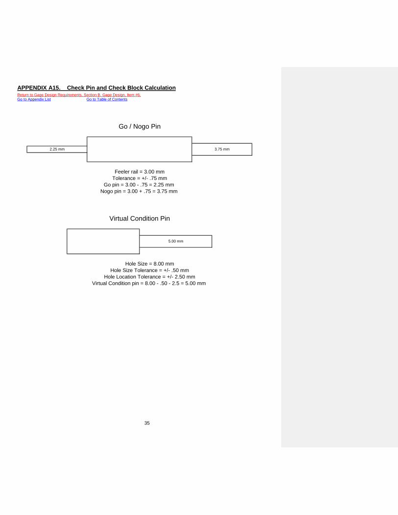
35
APPENDIX A15. Check Pin and Check Block Calculation Return to Gage Design Requirements, Section B. Gage Design, Item #6. Go to Appendix List Go to Table of Contents
Hole Size = 8.00 mm
Hole Location Tolerance = +/- 2.50 mmVirtual Condition pin = 8.00 - .50 - 2.5 = 5.00 mm
Hole Size Tolerance = +/- .50 mm
5.00 mm
Go pin = 3.00 - .75 = 2.25 mm Nogo pin = 3.00 + .75 = 3.75 mm
Feeler rail = 3.00 mm
Virtual Condition Pin
Go / Nogo Pin
2.25 mm 3.75 mm
Tolerance = +/- .75 mm

36
APPENDIX A16. Ergonomic Repetition Benchmarks matrix Return to Safety and Ergonomic Requirements, Item #9. Go to Appendix List Go to Table of Contents
LOW MODERATE HIGH
Leisurely Pace Frequent Pauses
Non-cyclical Tasks
Steady Pace Infrequent Pauses
Rapid Pace No Rest Pauses
Bottleneck Stations High Frequency of Similar Tasks
Repetition Benchmarks
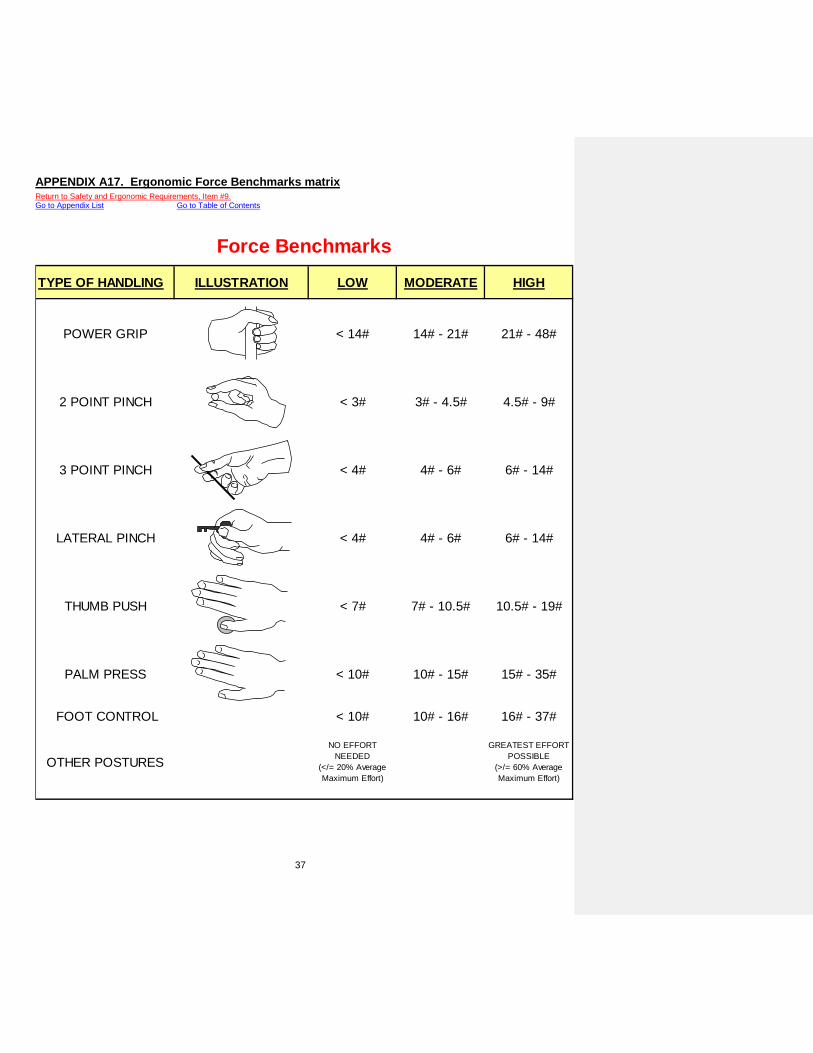
37
APPENDIX A17. Ergonomic Force Benchmarks matrix Return to Safety and Ergonomic Requirements, Item #9. Go to Appendix List Go to Table of Contents
TYPE OF HANDLING ILLUSTRATION LOW MODERATE HIGH
POWER GRIP < 14# 14# - 21# 21# - 48#
2 POINT PINCH < 3# 3# - 4.5# 4.5# - 9#
3 POINT PINCH < 4# 4# - 6# 6# - 14#
LATERAL PINCH < 4# 4# - 6# 6# - 14#
THUMB PUSH < 7# 7# - 10.5# 10.5# - 19#
PALM PRESS < 10# 10# - 15# 15# - 35#
FOOT CONTROL < 10# 10# - 16# 16# - 37#
OTHER POSTURESNO EFFORT
NEEDED (</= 20% Average Maximum Effort)
GREATEST EFFORT POSSIBLE
(>/= 60% Average Maximum Effort)
Force Benchmarks

38
APPENDIX A18. Ergonomic Posture Benchmarks matrix (page 1) Return to Safety and Ergonomic Requirements, Item #9. Go to Appendix List Go to Table of Contents
OR
unsupported
hand/forearm
>15º ULNAR DEVIATED WRIST
NEUTRAL & RELAXED FINGER GRIP
TENSED / AWKWARD FINGER GRIP
TENSED / AWKWARD FINGER GRIP
Posture BenchmarksLow Risk Moderate Risk High Risk
REACH & UNSUPPORTED FOREARM
SUPPORTED or NEUTRAL UPPER ARM
REACHING / SHOULDER <60º FLEXION
REACHING / SHOULDER >60º FLEXION
HAND and
WRIST
0-15º EXTENSION 15 - 30º EXTENSION 0 - 15º FLEXION
30 º EXTENSION >15º FLEXION
0-15º ULNAR DEVIATED WRIST 5-15º ULNAR DEVIATED WRIST
NUETRAL SHOULDERS SLOUCHED / FORWARD SHOULDERS
ASSYMETRICAL / TENSED SHOULDERS
ARM and SHOULDER
RELAXED or SUPPORTED ELBOW
<45º EXTENDED >70º FLEXION ELBOW
<70º FLEXION ELBOW
NEUTRAL or SUPPORTED FOREARM
UNSUPPORTED FOREARM

39
APPENDIX A18. Ergonomic Posture Benchmarks matrix (page 2) Return to Safety and Ergonomic Requirements, Item #9. Go to Appendix List Go to Table of Contents
Posture BenchmarksLow Risk Moderate Risk High Risk
HEAD &
NECK
NUETRAL <15º FLEXION & CHIN IN >15º FLEXION or CHIN PROTRUDED
Torso
RECLINE VERTICAL FLEXED
SYMETRICAL TWISTED BEND / REACH / LIFT
VIEW
ANGLE
15 - 30º <15 or <30º >10 or <35º
VIEW
DISTANCE
15" - 24" TO SCREEN 14" - 16" TO DOCUMENT <16" TO SCREEN 8" - 12" TO SCREEN
OR HIGH RESOLUTION

40
Go to Table of Contents APPENDIX B - Diagrams
DESCRIPTION APPENDIX # PAGE # Toggle Clamp with Handle Stop B1 41
Toggle Clamp with Lock-out Pin B2 42
Hinged Drop Detail with Lock-out Pin B3 43
Minimum CMM Probe Access Distance B4 44
Gage Base Size B5 45
Tooling Ball Labeling B6 46
Go / NoGo Gage and Screw Pin Tethering and Storage B7 47
Removable Detail Tethering and Storage B8 48
Details Overhanging Base B9 49
J-Corner Identification B10 50
Jig Foot Location B11 51
Base Thickness Uniformity B12 52
Hole Clearance for CMM Access B13 53
Bullet Nose Dowel Location B14 54
Locating Pin with Lock-out Pin B15 55
Bayonet Clamp Location to Allow for CMM Access B16 56
Clamp Lock-out Mechanism B17 57
Handle Installation B18 58
Forklift Sleeve Installation B19 59
Datum Scheme for Base Certification B20 60
Gage Certification Datum Set-up B21 61
Check direction / Non-check Direction for Certification B22 62
Fastener Pin Representation B23 63
Eyebolt Installation B24 64
Tooling Ball Origin Identification B25 65
Clamping Direction B26 66
Tooling Hole B27 67
Certification of 2-way on a Slide B28 68

41
APPENDIX B1. Toggle Clamp with Handle Stop Return to Safety and Ergonomic Requirements, Item #4. Go to Appendix List Go to Table of Contents
PINCH POINT
HANDLE STOP
PINCH POINT

42
APPENDIX B2. Toggle Clamp with Lock-out Pin Return to Safety and Ergonomic Requirements, Item #4. Go to Appendix List Go to Table of Contents
CLAMP
LOCK OUT PIN
TETHERING CABLE

43
APPENDIX B3. Hinge Drop Detail with Lock-out Pin Return to Safety and Ergonomic Requirements, Item #4. Return to Build Requirements, Section F. Hinged Details, Item #1. Go to Appendix List Go to Table of Contents
HINGED DETAIL
LOCK OUT PIN
TETHERING CABLE
VIEW IN DIRECTION OF ARROW "A"
HINGED DETAIL
LOCK OUT PIN
TETHERING CABLE

44
APPENDIX B4. Minimum CMM Probe Access Distance Return to Quotation Requirements, Item #4. Go to Appendix List Go to Table of Contents
MIN 9"
PART
BASE
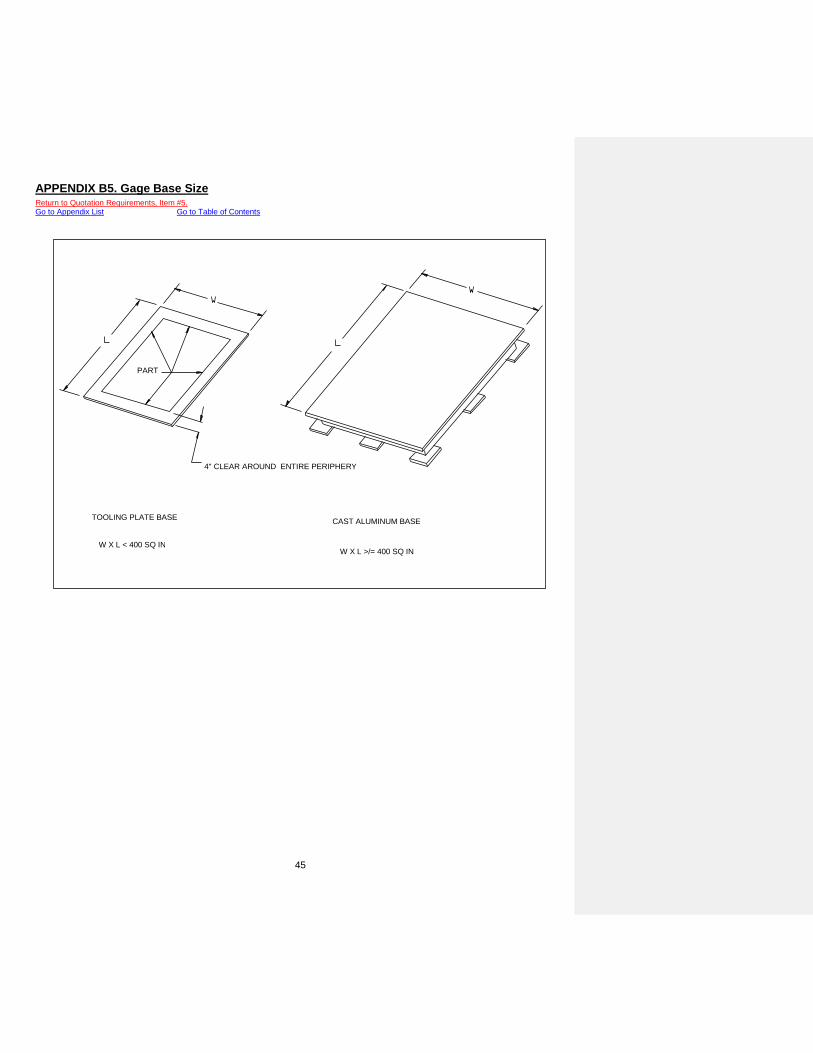
45
APPENDIX B5. Gage Base Size Return to Quotation Requirements, Item #5. Go to Appendix List Go to Table of Contents
CAST ALUMINUM BASE
W X L >/= 400 SQ IN
TOOLING PLATE BASE
W X L < 400 SQ IN
4" CLEAR AROUND ENTIRE PERIPHERY
PART
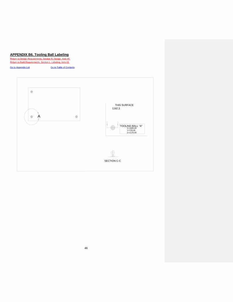
46
APPENDIX B6. Tooling Ball Labeling Return to Design Requirements, Section B. Design, Item #8. Return to Build Requirements, Section L. Labeling, Item #3. Go to Appendix List Go to Table of Contents
A
SECTION C-C
TOOLING BALL "A" X=1600.00 Y=725.00 Z=1175.00
THIS SURFACE 1162.3

47
APPENDIX B7. Go / NoGo Gage and Screw Pin Tethering and Storage Return to Design Requirements, Section B. Gage Design, Item #14. Go to Appendix List Go to Table of Contents
SCREW PIN Go/Nogo GAGE

48
APPENDIX B8. Removable Detail Tethering and Storage Return to Design Requirements, Section B. Gage Design, Item #14. Go to Appendix List Go to Table of Contents
BULLET NOSE DOWEL
WORKING AREA STORAGE AREA
BUSHING BULLET NOSE DOWEL
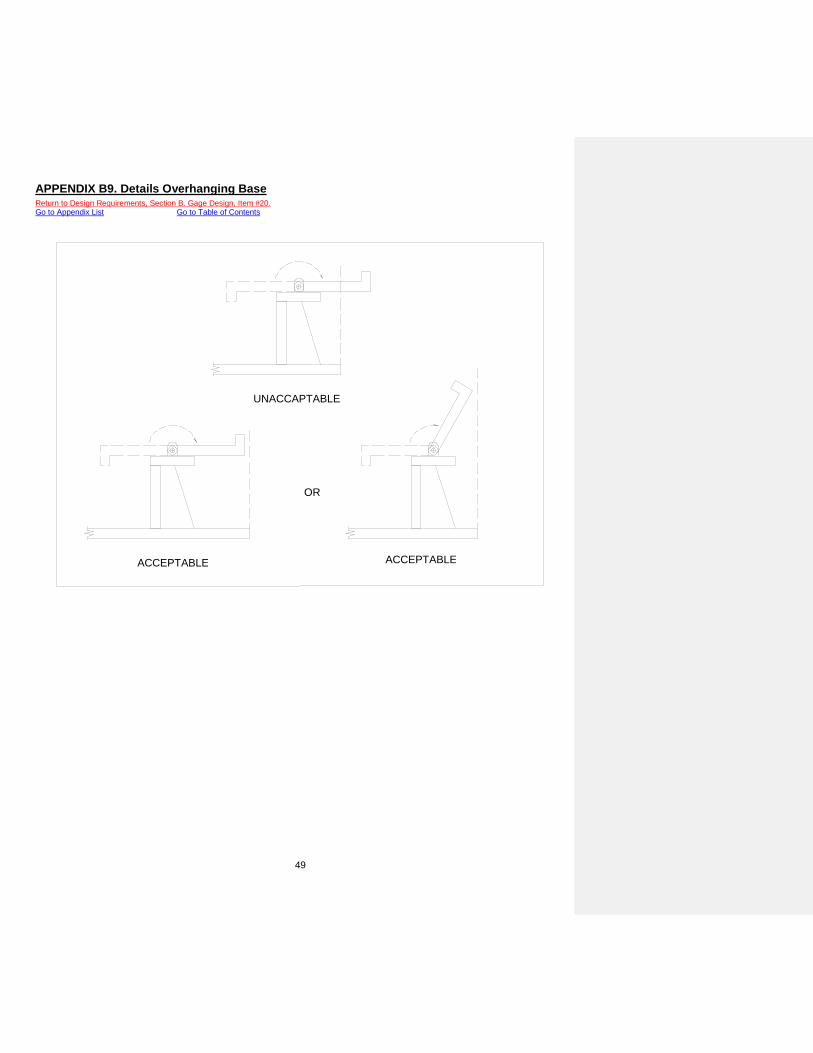
49
APPENDIX B9. Details Overhanging Base Return to Design Requirements, Section B. Gage Design, Item #20. Go to Appendix List Go to Table of Contents
ACCEPTABLE ACCEPTABLE
OR
UNACCAPTABLE

50
APPENDIX B10. J-Corner Identification Return to Build Requirements, Section A. Bases, Item #3. Go to Appendix List Go to Table of Contents
THIS SURFACE 450.0 ΜΜ

51
APPENDIX B11. Jig Foot Location Return to Build Requirements, Section A. Bases, Item #4. Go to Appendix List Go to Table of Contents
< 200 sq. in > 200 sq. in

52
APPENDIX B12. Base Thickness Uniformity Return to Build Requirements, Section A. Bases, Item #6. Go to Appendix List Go to Table of Contents

53
APPENDIX B13. Hole Clearance for CMM Access Return to Build Requirements, Section D. Details, Item #7. Go to Appendix List Go to Table of Contents
PART PART
Clearance

54
APPENDIX B14. Bullet Nose Dowel Location Return to Build Requirements, Section E. Removable Details, Item #1. Go to Appendix List Go to Table of Contents
BULLET NOSE DOWEL
BUSHING BULLET NOSE DOWEL

55
APPENDIX B15. Locating Pin with Lock-out Pin Return to Build Requirements, Section G. Locating Pins, Item #4. Go to Appendix List Go to Table of Contents
WORKING POSITION LOCK 0UT PIN POSITION

56
APPENDIX B16. Bayonet Clamp Location to Allow for CMM Access Return to Build Requirements, Section H. Clamps, Item #1. Go to Appendix List Go to Table of Contents
CLAMPED POSITION UNCLAMPED POSITION
PART PART
DOWEL DOWEL

57
APPENDIX B17. Clamp Lock-out Mechanism Return to Build Requirements, Section H. Clamps, Item #3. Go to Appendix List Go to Table of Contents

58
APPENDIX B18. Lift Handle Installation Return to Safety and Ergonomic Requirements, Item #6. Go to Appendix List Go to Table of Contents
TOTAL GAGE WEIGHT < 65 LBS TOTAL GAGE WEIGHT > 65 LBS < 100 LBS
22-30 INCHES 22-30 INCHES

59
APPENDIX B19. Forklift Sleeve Installation Return to Safety and Ergonomic Requirements, Item #6. Go to Appendix List Go to Table of Contents
OVERALL GAGE WEIGHT > 100 LBS
* - 4” Riser Blocks may be attached to base feet for cart.
Forklift Lifting Area

60
APPENDIX B20. Datum Scheme for Base Certification Return to Build Requirements, Section A. Bases, Item #1. Go to Appendix List Go to Table of Contents
*DATUM "A" REFERENCE
BOTTOM OF JIG FEET
BOTTOM OF BASE
BOTTOM VIEW
* DATUM "A" REFERENCE (WITH JIG FEET) ** DATUM "A" REFERENCE (WITHOUT JIG FEET)

61
APPENDIX B21. Gage Certification Datum Set-up Return to Build Requirements, Section K. Build Tolerances, Note #1. Go to Appendix List Go to Table of Contents

62
APPENDIX B22. Check Direction / Non-check Direction for Certification Return to Build Requirements, Section K. Gage Build Tolerances, Note #2. Return to Build Requirements, Section K. Gage Build Tolerances, Note #3. Go to Appendix List Go to Table of Contents
ROUND LOCATOR (4-WAY) ROUND LOCATOR (2-WAY)
NON-CHECK DIRECTION
NON-CHECK DIRECTION
NON-CHECK DIRECTION
NON-CHECK DIRECTION
NON-CHECK DIRECTION
NON-CHECK DIRECTION
NON-CHECK DIRECTION
CHECK DIRECTION
CHECK DIRECTION CHECK
DIRECTION
DIRECTION CHECK
SPC POINT NET PAD
NET SURFACE
ATTRIBUTE RAIL
DIRECTION CHECK
NET NET NO NO

63
APPENDIX B23. Fastener Pin Representation Return to Build Requirements, Section D. Details, Item #10. Go to Appendix List Go to Table of Contents

64
APPENDIX B24. Eyebolt Installation Return to Safety and Ergonomic Requirements, Item #6. Go to Appendix List Go to Table of Contents

65
APPENDIX B25. Tooling Ball Origin Identification Return to Build Requirements, Section A. Bases, Item #1. Go to Appendix List Go to Table of Contents
Origin
Origin
Origin

66
APPENDIX B26. Clamping Direction Return to Build Requirements, Section H. Clamps, Item #2. Go to Appendix List Go to Table of Contents

67
APPENDIX B27. Tooling Hole and Surface Target Labeling Return to Design Requirements, Section B. Design, Item #8. Return to Build Requirements, Section L. Labeling, Item #3. Go to Appendix List Go to Table of Contents

68
APPENDIX B28. Certification of 2-way on a Slide Return to Build Requirements, Section N. Gage Certification, Item #5. Go to Appendix List Go to Table of Contents
AND
(1 of the 2 selections)
OR

69
Go to Table of Contents
APPENDIX C – STANDARD MATERIAL LIST Return to Quotation Requirements, Item #2.
Material Product Code (grade) Applications*
Aluminum 6061 Details, Flush/feeler rails
Mic 6 Tooling Plate Bases
Steel 1018 Details, Net pads, Sheet metal representations 1020 Details, Net pads, Sheet metal representations
Fixture Plank
MP 1055 Flush / feeler rails, Attribute tub fixtures, Sheet metal representations MP1054 Flush / feeler rails, Attribute tub fixtures, Sheet metal representations
Prolab 65 Flush / feeler rails, Attribute tub fixtures, Sheet metal representations Lab 1000 Flush / feeler rails, Attribute tub fixtures, Sheet metal representations
Ren Shape 450 Flush / feeler rails, Attribute tub fixtures, Sheet metal representations Ren Shape 470 Flush / feeler rails, Attribute tub fixtures, Sheet metal representations
• Applications refer to examples and are not intended to be finite.

70
Go to Table of Contents
APPENDIX D – REVISION TABLE
Level Date Description Release 03/15/02 a. Release for publication.
001 11/07/02 a. Added Gage Supplier signatures to Introduction page. b. Added note to Gage Build Requirements - Section K. Build Tolerance, All tolerances are in
millimeters unless otherwise noted. c. Updated Gage Build Requirements - Section K. Build Tolerances to include the Check pin
location tolerance. d. Updated Gage Build Requirements - Section K. Build Tolerances to include Go and Nogo pin
size tolerances. 002 03/03/04 a. Changed Automotive Systems Group to Automotive Group. 003 05/05/04 a. Added reference to Gage Assumption/Gage Cost Model form in General Requirements #1
and #10. b. Added reference to Gage Assumption/Gage Cost Model form in Quotation Requirements #8. c. Added Quotation Requirements #9, referencing customer cost breakdowns using the Gage
Assumptions / Gage Cost Model form. d. Revised wording of Gage Design Requirements - Section B. Gage Design #16 for
clarification. e. Moved Gage Build Requirements - Section H Clamps #1 to Gage Design Requirements -
Section B. Gage Design #23. Also, reworded entry for clarification. f. Revised wording of Gage Build Requirements - Section D. Details #1 for clarification. g. Revised wording of Gage Build Requirements - Section D. Details #4 for clarification. h. Revised wording of Gage Build Requirements - Section D. Details #5 for clarification. i. Revised wording of Gage Build Requirements - Section I Scribe Lines / Tolerance Bands #1
for clarification. j. Revised wording of Gage Build Requirements - Section I Scribe Lines / Tolerance Bands #2
for clarification. k. Revised wording of Gage Build Requirements - Section J SPC Indicators #2 for clarification. l. Changed Gage Build Requirements - Section K SPC Indicators #3 entry from center of
indicator travel to approximate center of indicator travel. m. Changed Gage Build Requirements - Section K SPC Indicators #8 reference from tips must
be secure to tips must be tightened. n. Revised wording of Gage Build Requirements - Section K SPC Indicators #9 for clarification. o. Revised wording of Gage Build Requirements - Section L Labeling #5 for clarification. p. Revised wording of Gage Build Requirements - Section N Gage Certification #1 for
clarification. q. Revised wording of Gage Build Requirements - Section N Gage Certification #2 for
clarification. r. Changed Gage Build Requirements - Section N Gage Certification #2 entry from one-
direction check like a flush or feeler rail to one-direction check like a net point, flush rail, or feeler rail.
s. Changed Gage Build Requirements - Section O Third Party Certification #3 entry by adding up to and including the internal and Third Party recertification.
t. Changed Gage Build Requirements - Section P Gage Instructions #2 entry from it must include to they must include.
u. Revised wording of Gage Build Requirements - Section Q Function Check #1 for clarification. v. Added Gage Assumption / Gage Cost Model to Appendix A – Documents as Appendix A19.
004 07/25/06 a. Changed all references of Gage Buyer to Gage Engineer. b. Corrected the Quotation Requirements #7 entry by changing the 600 in² reference to 400 in². c. Changed Gage Design Requirements - Section B. Gage Design #8 to include Tooling Holes
and Surface Target. Added Tooling Holes and Surface Target picture to Appendix B – Diagrams as Appendix B27.
d. Added wording to Gage Design Requirements - Section B. Gage Design #19 to include, including details that move (toggle clamps, hinge drops, etc.)
e. Changed Gage Build Requirements - Section B. Tooling Balls to include reference to Tooling Holes.

71
f. Changed Table of Contents Gage Build Requirements – Section B to include Tooling Holes. g. Renumbered Table of Contents. h. Added reference to Gage Build Requirements - Section B. #1 to include Tooling Holes. i. Changed Gage Build Requirements - Section B. #2 to include reference for Tooling Holes
size requirement. j. Changed Gage Build Requirements - Section I. Scribe Lines / Tolerance Bands #4 to have
scribe lines on the gage base as an option, as determined by the Customer or YF Representative.
k. Changed Gage Build Requirements – Section K. Build Tolerances Note #1 to include the reference of tooling holes.
l. Changed Gage Build Requirements – Section L. Labeling #3 to include the reference of tooling holes.
005 12/01/12 a. Added YF Supplier Portal header and footer to cover page.
006 07/29/17
a. Changed all references of Johnson Controls or JCI to Yanfeng Global Automotive Interiors or YF.
b. Updated wording throughout standard. c. Added Gage Build Requirement – Section J. SPC Indicators to include all indicators must
have a minimum metric discrimination of three (3) decimal places (.001 mm). d. Added Gage Build Requirement – Section J. SPC Indicators to include all indicators must
have a dimensional certification, from the manufacturer, when shipped from the gage supplier.
e. Added Gage Build Requirement – Section J. SPC Indicators to include all indicator collars must be placed within +/- 1.0 mm of the indicator’s center of travel.
f. Added Gage Build Requirement – Section J. SPC Indicators to include all indicators must be identified with the gage supplier’s job number & SPC identification:
NON-SYMMETRICAL PARTS Quantity / Type of SPC port Terminology 1 SPC port on gage 1234-1 2 (or more) SPC ports on gage 1234-1/2/3/… SYMMETRICAL PARTS Quantity / Type of SPC port Terminology 1 SPC port for each hand on gage 1234LR-1 2 (or more) SPC ports for each hand on gage 1234LR-1/2/3/…
g. Added Gage Build Requirement – Section K. Build Tolerances to include tolerance for 2-way on slide (pinned at center & pinned at one end)
Ø 0.10 A B C Pinned at center of travel
0.10 A B C Pinned at end of travel (checked ¼to slide travel) h. Added Gage Build Requirement – Section L. Labeling to include all indicators must be
identified with the gage supplier’s job number & SPC identification: i. Added Gage Build Requirement – Section N. Gage Certification to include all two way
locators on a slide, must be certified in the center and at one end of the slide’s full travel. Each location must be pinned (for certification) and clearly identified on the gage certification.
j. Revise Gage Build Requirement – Section R. Measurement System Analysis to make section better defined.
k. Revise Gage Build Requirement – Section R. Measurement System Analysis to make section more clear. Added new requirements for plant representative.
l. Updated Appendix F – Glossary of Terms to include definitions for LMB, MMB, RMB, CC, IC and SC.
007 12/6/17
a. Changed Gage Build Requirement – Section K. Build Tolerances for net pads, in the check direction
0.10 A B C Check Direction
b. Changed Gage Build Requirement – Section K. Build Tolerances for SPC ports, in the check direction
0.20 A B C Check Direction

72

73
Go to Table of Contents
APPENDIX E – REFERENCE LIST
Reference Title Author / Publisher Publish D t ASME Y14.5-1994 Geometric Dimensioning and Tolerancing ASME 1/95
CG Model and Fixture Gage Build Standards CG Model and Fixture Unknown
Chrysler Truck Platform Interior Systems Dimensional Quality Plan DaimlerChrylser Corporation – Truck Platform 6/00
Chrysler AME Gage Standards DaimlerChrylser Corporation 9/98 Chrysler Corporation Checking Fixture Design and Build Standards DaimlerChrylser Corporation 4/93 Ford Vehicle Operations Final Assembly Engineering Tooling Aids –
Design and Build Guidelines Ford Motor Company 2/97
GM Checking Fixture/Gage Standards (PED:114) General Motors 10/01 GM Global Checking Fixture Standards General Motors 9/99
GM Mid/Lux Supplier Development/Quality Part Fixturing Design/Build Standards
General Motors Mid/Lux Division 4/96
ISO Guide 25 Laboratory Certification ISO / IEC 12/90 ISO / IEC 17025 Laboratory Certification ISO / IEC 12/90
Jay Enn Gage Build Standards Jay Enn Corporation 1/97 Yanfeng Athens Plant General Gage Specifications Yanfeng Athens 6/98
Yanfeng Interiors Special Equipment General Specifications Yanfeng Equipment Development Team 5/01
Yanfeng Interiors Special Equipment General Specifications Yanfeng Equipment Development Team 5/01
Yanfeng Thermobond Headliner Substrate Standards Yanfeng Tooling 12/99 Yanfeng Acousticor Headliner Substrate Standards Yanfeng Tooling 10/98
Yanfeng Honda Business Unit Gage and Fixture Criteria Yanfeng Honda BU 4/99 Yanfeng Injection Mold Standards Yanfeng Tooling 1/00
Yanfeng Integration Center Gage (CMM Fixture) Development Criteria Yanfeng Integration Center 3/99 Yanfeng Lakeshore Gage Standards Yanfeng Lakeshore Unknown
Yanfeng Reynosa Plant General Gage Specifications Yanfeng Reynosa 9/99
Measurement Systems Analysis Reference Manual Chrysler/Ford/General Motors Supplier Quality Requirements
Task Force 6/98
MMMA Checking Fixture Tolerance Standard Mazda Motors 5/90 MP Components Gage Build Standards MP Components 1/99
Peterson Jig and Fixture, Inc. Fixture Build Standards Peterson Jig and Fixture Unknown
Quality Systems Requirements - QS9000 Manual Chrysler/Ford/General Motors Supplier Quality Requirements
Task Force 3/98
Quality Systems Requirements – Tooling & Equipment Supplement Chrysler/Ford/General Motors
Tooling and Equipment Representatives
6/98
Supplier Quality Assurance Manual for Parts and Components (Section 17 – Checking Fixtures, Gages and Test Equipment)
Toyota Motor Manufacturing North America, Inc. 3/00

74
Go to Table of Contents
APPENDIX F – GLOSSARY OF TERMS Return to General Requirements Return to Safety and Ergonomics Requirements Return to Quotation Requirements
Return to Gage Design Requirements Return to Gage Build Requirements (Pass cursor over term to read definition.)
2-way locator 4-way locator 90º out of body 180º out of body A2LA Accuracy Analysis of variance (ANOVA)
Anthropometry Appraiser variation (AV)
ASME Y14.5M-1994
ASME Y14.5.1M-1994 Attribute rail Attribute study Base
Bayonet clamp Bias Body position Bullet-nose dowel Bushing Calibration Cartesian coordinate system
Cast aluminum base CC Certification Certification target Clamp Clamping direction Clamp pressure
Concept drawing Contour template Coordinate measuring machine Datum Datum Axis Datum feature Datum point
Datum reference frame Datum surface Datum target Design approval Detail Discrimination Drop template
Equipment variation (EV) Feeler rail Fixture Fixture plank Flatness Flush rail Gage
Gage design Gage R study Gage R&R study Gage instructions Gaging tolerance Geometric
Dimensioning and Tolerancing
Go/NoGo pin
Hinge drop IC IGES I-J-K check Inspection ISO Guide 25 ISO Guide 17025
J corner Jig feet Linearity LMB LMC Maintainability Master set block
Mean Time Between Failures
Mean Time Between
Maintenance
Mean Time to Repair Measurement Measurement
system Measurement
system analysis Measurement system error
Measurement uncertainty Microslide MMB LMC NC machining Net surface Out of calibration
Operator’s area of movement Parallax error Parallelism Part Alignment Part orientation Phase I gage Phase II gage
Pinch point Plug gage Precision Primary datum Profile of a line Profile of a surface QAF
QS9000 Reliability Repeatability (EV) Reproducibility (AV) Resolution RFS RMB
Riser SC Scribe line Secondary datum Set two check one check
Sheet metal Representation
Significant characteristic
Simulated datum Site check SPC indicator SPC port Squareness Stability Stanchion
Start Coordinates Step gage Sub-base TE9000 Tertiary datum Third party certification Toggle clamp
Tooling ball Tooling plate Total variation True position Tulip Vector check Virtual condition
Warranty X-Y-Z coordinate system
Commented [D1]: A 2-way locator is a detail that ...
Commented [D2]: A 4-way locator is a detail that ...
Commented [D3]: 90º out of body defines the part ...
Commented [D4]: 180º out of body defines the part ...
Commented [D5]: American Association for Laboratory ...Commented [D6]: Accuracy is defined as the closeness ...
Commented [D7]: ANOVA is a statistical technique for ...Commented [D8]: The study of the characteristics of ...
Commented [D9]: See Reproducibility.
Commented [D10]: ASME Y14.5M-1994 is a ...
Commented [D11]: ASME Y14.5.1M-1994 describes ...
Commented [D12]: An attribute rail is a gage detail that ...
Commented [D13]: An Attribute study analyzes the ...
Commented [D14]: The base is the foundation for the ...
Commented [D15]: A bayonet clamp is a clamp that is ...Commented [D16]: Bias is the difference between the ...Commented [D17]: Body position refers to the ...
Commented [D18]: A bullet – nose dowel is a hardened ...
Commented [D19]: A bushing is a detail that is ...
Commented [D20]: Calibration is the comparison of a ...Commented [D21]: A three dimensional system ...
Commented [D22]: A cast aluminum base is a type of ...
Commented [D23]: Critical Characteristic. Designates ...Commented [D24]: The gage certification is a ...
Commented [D25]: A certification target is an area on ...Commented [D26]: A clamp is a device that is used to ...Commented [D27]: The clamping direction is the ...
Commented [D28]: The clamp pressure refers to the ...
Commented [D29]: A Concept drawing is a sketch of ...Commented [D30]: A Contour template is a detail that ...
Commented [D31]: A Coordinate Measuring Machine ...
Commented [D32]: A datum is a theoretically exact ...
Commented [D33]: A datum axis is an axis of a part ...
Commented [D34]: A datum feature is a feature on the ...Commented [D35]: A datum point is a single coordinate ...
Commented [D36]: The datum reference frame refers ...
Commented [D37]: A datum surface is an area of the ...Commented [D38]: A datum target is a theoretically ...
Commented [D39]: Design approval is a signature on ...Commented [D40]: A detail is a component of the gage ...
Commented [D41]: Discrimination refers to how finite ...Commented [D42]: A drop template is a detail that is ...
Commented [D43]: See Repeatability.
Commented [D44]: A feeler rail is an attribute rail that ...Commented [D45]: A fixture is defined as a device that ...
Commented [D46]: Fixture plank is a plastic composite ...
Commented [D47]: Flatness is a geometric control of ...Commented [D48]: A flush rail is an attribute rail that ...
Commented [D49]: A gage is defined as an instrument ...
Commented [D50]: A Gage design is a drawing (print) ...Commented [D51]: A Gage R (Repeatability) study ...
Commented [D52]: A Gage R&R (Repeatability & ...
...
...
...
...
...
...
...
...
...