___xxx
TRANSCRIPT
A LEARNING TOOL FOR CELLULAR AIR INTERFACES (GSM, GPRS, UMTS, AND WLAN)
By
OLUFEMI JAMES OYEDAPO
Submitted in partial fulfilment of the requirements for the degree
MAGISTER TECHNOLOGIAE: ELECTRICAL ENGINEERING – TELECOMMUNICATIONS TECHNOLOGY
In the
School of Electrical Engineering French South African Institute in Electronics
FACULTY OF ENGINEERING
TSHWANE UNIVERSITY OF TECHNOLOGY
Supervisor at ENST-Paris: Philippe Martins
TUT Supervisor: Ben Van Wyk
September 2005
DECLARATION “I hereby declare that the dissertation/thesis submitted for the degree M.Tech: Electrical
Engineering- Telecommunications Technology, at Tshwane University of Technology, is
my own original work and has not previously been submitted to any institution of higher
education. I further declare that all sources cited or quoted are indicated and
acknowledged by means of a comprehensive list of references”.
O.J. Oyedapo Copyright© Tshwane University of Technology 2005

DEDICATION
With gratitude to God, I dedicate this work to my wife Beverly, and my children Anjola
and Isaiah.

ACKNOWLEDGEMENT
I would like to thank the French South African Technical Institute in Electronics
(F’SATIE) and the government of île-de-France for the financial support I enjoyed
throughout the period of this programme.
My profound gratitude to Dr Philippe Martins of the INFRES department of Ecole
National Supérieure des Telecommunications (ENST-Paris) for his immeasurable
guidance and supervision; thanks also go to Professor Philippe Godlewski, Professor
Xavier Lagrange and Nicolas Daily whose previous work I benefited from. I also
appreciate the effort of Professor Ben van Wyk and Mr Damien Chatelain for their
directives during the compilation of my periodical reports and the final thesis; I would
like to thank my HOD, Professor Adisa Jimoh and the Dean of the faculty of Engineering
TUT for their support throughout my period of stay in France – God bless you all.

ABSTRACT
One of the difficulties encountered in the teaching of mobile radio networks is to present
in a simple way the interaction and the sequencing of various tasks, which must be
carried out by the mobile station (MS) and the network over the air interface. The
comprehension of these processes is facilitated when they are presented in a visual form
that can be understood in real-time, when the common MS-Network tasks such as voice
call (MS oriented or MS terminated), short message service (SMS) are going on. This
work describes the architecture of the VIGIE (Visualisation and Interpretation of
GSM/GPRS for Institutes & Ecole) software, developed in Java to display the exchanges
of these tasks between the MS and the network. The uniqueness in the architecture of this
tool is revealed in terms of its modularity. Finally the current work done on the
development of the General Packet Radio Service (GPRS) logical screen and the
Downlink Signalling Counter (DSC) graphical screen are described.

CONTENTS DECLARATION……………………………………………………………………i DEDICATION………………………………………………………………………ii ACKNOWLEDGEMENT…………………………………………………………..iii ABSTRACT…………………………………………………………………………iv TABLE OF CONTENT……………………………………………………………..v-vi CHAPTERS 1 INTRODUCTION…………………………………………………………1
1.1 Project Aims...………………………………………………………1-2 1.2 Main Contribution…………………………………………………..2 1.3 Chapters Outline…………………………………………………….2-3
2 LITERATURE REVIEW…………………………………………………4 2.1 Chapter Introduction………………………………………………...4-5 2.2 Review of the GSM and GPRS Principles………………………….5-11 2.3 VIGIE Principle of Operation ………………………………………11 2.3.1 Review of the Architecture………………………………….11-12 2.3.2 Functionalities ………………………………………………13 2.4 VIGIE Architecture ………………………………………………13-16 2.5 Software Description………………………………………………..17-18 2.6 Chapter Conclusion…..……………………………………………..18-19 3 JOURNAL ARTICLE…………………………………………………….20 3.1 Chapter Introduction ……………………………………………….20-22 3.2 Journal Paper Presented ……………………………………………23-35 4 DEVELOPMENT, RESULT AND CONCLUSION…………………….36 4.1 Chapter Introduction………………………………………………..36
4.2 The Concrete Syntax Notation (CSN) ……………………………...36-38 4.3 Coding the DSC Window and the GPRS Resource Allocation
Window……………………………………………………………..38 4.3.1 Writing Java Code for the DSC Window……..……………38-41 4.3.2 Writing the Java Code for the GPRS Resource Allocation Window…………………………………………………….41-48
4.4 Results ……………………………………………………………..48 4.4.1 DSC …………………………………………………….….48-50 4.4.2 GPRS Logical Screen …………………………………...…50-52

4.4.3 Integration with Existing Modules (Windows)……………53-54 4.5 Demonstration of the Tool…………………………………………54-56 4.6 Future Work ……………………………………………….………56 4.7 Final Conclusion ………………………………………….……….57 References……………………………………………………………………….. 58-60
Appendix A GSM ………………………………………………………………61 A1 System Elements………………………………………..…61 A2 Network Architecture and Protocol Layers ………………62-69 A3 GSM Radio Interface……………………………………...69-80 A4 The MS in Communication Mode………………………...80-85 Appendix B GPRS………………………………………………………………86 B1 The GPRS Architecture……………………………………86-89 B2 The Transmission and the signalling Plane………………..89-96 B3 The GPRS Radio Interface………………………………...96-103 B4 GPRS Traffic Cases ………………………………………103-110 B5 Mobility …………………………………………………..110-113 B6 Radio Interface: RLC/MAC Layer ……………………….113-118 Appendix C Sagem OTxxx Series Protocol Specifications………………….119 C1 General Aspect of the Frame of the Trace Mobile………..120-121 C2 The OTR Application Protocol …………………………..121-124 C3 QoS Messages ……………………………………………124-125 C4 The Layer State and Measurement Information Messages.125-126 C5 MAC Information ………………………………………...126-127 Appendix D Decoding of GSM L3, GPRS L3, and RLC/MAC Control
Messages………………………………………………………….128 D1 Decoding of GSM Layer 3 RR Messages ………………...128-138 D2 GPRS Layer 3 and RLC/MAC Control Messages ………..138-153
Appendix E Java code………………………………………………………….154

1
CHAPTER 1
INTRODUCTION In 1996, the development of a software tool called GSMShow to assist in the teaching
and visualization of Global System for Mobile Communications (GSM) protocol over the
air interface was initiated. By 2000 GSMShow was fully developed and functional. The
GSMShow is used on a computer connected via a serial link to a GSM trace mobile. A
trace mobile is similar to any mobile handset in every respect and can be used on any
operational network except that it has the characteristic to send in “rough form” (a
succession of bytes) the messages exchanged between the network and its measurements
and calculations. This software displays in a convivial form the exchanges between the
network and the trace mobile. Users thus see the exchange of these frames from different
points of view; each point of view is what led to the development of different windows
where users can monitor specific behavior of the mobile to the network. The advent of
General Packet Radio Service (GPRS) in 2001 led to the development of a new software
tool called VIGIE by ENST-Paris and ENST-Bretagne. VIGIE is a teaching aid for
mobile networks and its particularly adapted to render comprehensible, the principle of
encapsulation (joint visualization of layers 2 and 3), frequency hopping, management of
timing advance (TA) and power control, logical channels, activation of GPRS sessions
and so on. It also displays the sequencing of messages for various services. This software
is developed in Java, to potentially make it more evolutional than its predecessor
(GSMShow). It supports the GSM/GPRS protocol and also can be to be potentially
interfaced with any trace mobile. In the future, with the development of an adequate
driver, VIGIE will be able to support Enhanced Data rates for GSM Evolution (EDGE),
Universal Mobile Telephone Service (UMTS), or Wireless Local Area Network (WLAN)
protocols.
1.1 Project Aims One of the difficulties encountered in the teaching of mobile radio network protocols and
advanced cellular networks is to present in a simple way the interaction and the

2
sequencing of various tasks, which must be carried out by the Mobile Station (MS) and
the network over the air interface. The comprehension of these processes is facilitated
when they are presented in a visual form that can be understood in real-time, when the
common MS-Network tasks such as voice call (MS oriented or MS terminated), short
message service (SMS) are going on.
This project is aimed at developing software (in Java) for the visualisation of exchange
of protocols between a Mobile Station (trace) and the GSM-GPRS Network and
ultimately integrates it into VIGIE (a legacy software package for protocol visualisation).
This ultimately led to the development of a user interface for the monitoring of radio
resource allocation in GPRS network over the air interface called the GPRS logical
Screen, and the development of Downlink Signalling Counter (DSC) function for the
visual monitoring of cell reselection in a graphical format.
The user interfaces developed were integrated into the existing VIGIE architecture
1.2 Main Contribution One journal paper was published: VIGIE: A Learning Tool for Cellular Interfaces (GSM,
GPRS, UMTS, and WiFi), IPSI BgD Transactions on Internet Research, Special Issue on
E-Education: Concepts and Infrastructure, July 2005, Volume 1, Number 2 (ISSN 1820-
4503), Belgrade – see Chapter 2.
1.3 Chapter Outline In Chapter 2, basic knowledge of the GSM/GPRS system is introduced. More detail can
be found in Appendices A and B. The software’s functionality, description and
architecture are also covered.
Chapter 3 presents the journal paper that was published in the IPSI journal.. The fourth
Chapter outlines the steps and procedures involved in programming in Java, the user
interfaces developed and the final integration into the VIGIE software. It also presents the

3
results with special attention given to the GPRS logical screen and the DSC functionality.
This chapter also deals with the demonstration and the description of the interfaces
developed and future work.
4
CHAPTER 2
LITERATURE REVIEW 2.1 Chapter Introduction In 1982 the Conference of the European administrations of the Postal and
Telecommunications (CEPT) established the Groupe Spéciale Mobile (GSM) and the
aims were to develop Pan-European mobile network, support European roaming and
interoperability in landline, increase system capacity, provide advanced features,
Emphasise on standardization while maintaining supplier independence, and establish
low cost infrastructure and terminals.
By 1986 when the frequency band for GSM had been allocated, CEPT defined the GSM
radio interface as a mix of Time- and Frequency- Division Multiple Access (TDMA and
FDMA) with Frequency Division Duplex (FDD). In other words, channels are divided
both by frequencies (FDMA) and time slots (TDMA) while the uplink and downlink
channel for conversation are in separate frequencies (FDD).
In 1989 CEPT transferred all GSM standardization activities to the European
Telecommunications Standardization Institute (ETSI). ETSI kept the acronym GSM but
changed the official name to Global System for Mobile communications. Commercial
deployment began on a wide scale around 1992.
By 1991, the first GSM was ready to be brought into so-called friendly-user operation.
The same year witnessed the definition of the first derivative of GSM, the Digital
Cellular System 1800 (DCS 1800), which more or less translates the GSM system into
the 1800 MHz frequency range [2].
By 1992, many European countries had operational networks and GSM started to attract
interest worldwide. Time brought substantial technological progress to the GSM
hardware. GSM proved to be a major commercial success for system manufacturers as
well as for network operators [2].
5
ETSI created the third Generation Partnership Project (3GPP) in December 1998 with
other worldwide standard organization bodies. 3GPP is responsible for all GSM technical
specification work which involves the evolved radio access technologies such as GPRS
and Enhanced Data rates for Global Evolution (EDGE).
The following factors contributed to the success of GSM:
The liberalization of the monopoly of telecommunications in Europe during the
1990s and the resulting competition, which consequently lead to lower prices and
more “market”;
The knowledge-base and professional approach within the Groupe Spéciale
Mobile, together with the active cooperation of the industry;
The lack of competition: For example, in the United States and Japan, competitive
standards for mobile services started being defined only after (the success of)
GSM was already established.
With the Universal Mobile Telecommunications System (UMTS) network services being
deployed in France last year, the Japanese NTT DoComo (the first third-generation
mobile communications network based on Wideband- Code Division Multiple Access
(W-CDMA) technology together with the popular and successful I-mode) only the future
will tell which system will prevail as the next-generation of mobile communications.
2.2 Review of GSM and GPRS Principles
GSM utilises a cellular structure. The basic idea of a cellular network is to partition the
available frequency range, to assign only parts of that frequency spectrum to any base
transceiver station (see Figure 2.1), and to reduce the range of a base station in order to
reuse the scarce frequencies as often as possible. One of the main goals of planning is to
reduce interference between different base stations. Apart from the advantage of reusing
frequencies, a cellular network also comes with the following disadvantages:

6
(i) The cost of infrastructure increases as the number of base stations increases.
(ii) All cellular networks require what is called handover; that is as the MS moves
an active call is handed over from one cell to another.
(iii) The network has to be constantly informed of the approximate location of the
MS, even without a call in progress to be able to deliver an incoming call to
that MS.
One of the most important factors to be considered in mobile radio systems is the
frequency spectrum. To be able to make use of the bandwidth effectively, the system is
designed by means of the division of the service into neighbouring zones, or cells, which
in theory have a hexagonal shape. Each of these cells has a Base Transceiver Station
(BTS), which to avoid interference operates on a set of radio channels different from
those of the adjacent cells. This division permits the nonadjacent cells to use the same
frequencies. The grouping of cells that make use of the entire radio spectrum made
available to the operator is referred to as a cluster. The shape of a cell is irregular and is a
function of many constraints, such as the geographical terrain, propagation of the radio
signal in the presence of obstacles, availability of a spot for the BTS, and so on.
The diameter of cells in dense urban areas is often reduced to increase capacity, this is
allowed since the same frequency channels are used in a smaller area. The disadvantage
of using smaller cell diameter is an increase in co channel interference since this leads to
decrease in the distance necessary to reuse the frequencies (i.e. distance between two co
channel cells).
Figure 2.1 shows the basic examples of cluster organisation where a reuse pattern for
seven different frequencies f1 to f7 are shown. These frequencies correspond to beacon
carrier of each cell, on which signalling information is broadcast.

7
Figure 2.1 The GPRS is a packet-based data bearer service for wireless communication services that
is delivered as a network overlay for GSM, Code Division Multiple Access (CDMA) and
TDMA (ANSI-136) networks [4]. It applies a packet radio principle to transfer user data
packets in an efficient way between GSM MSs and external packet data networks. In
packet switching, data is split into packets and are transmitted separately and then
reassembled at the receiving end.
The GPRS is based on GSM communication and is intended to complement its existing
services. It supports the world’s leading packet based Internet communication protocols,
IP (Internet Protocols) and X.25, which enables any existing IP or X.25 applications to
operate over a GSM cellular connection. Its data speeds range from 14.4 kbits/s (using
one radio timeslot) to 115kbit/s (by combining all the 8 timeslots – in theory) and offer
continuous connection to the Internet for mobile phone and computer users. Appendix A
and B extensively covers the GSM and GPRS principles.
Appendix A discusses the general GSM system architecture and its essential
components. Subsection A2 further describes the GSM network architecture, identifying
different interfaces across which protocol exchange takes place. The MS, Base Station
System (BSS) and the Network and Switching Subsystem (NSS) basically forms a GSM
Network.
f5
f4 f1 f7
f6
f3 f2 f6f5
f1 f7f4
f3 f2
Cell Cluster
8
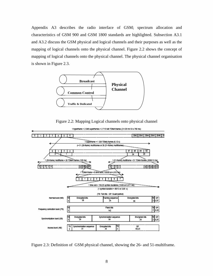
Appendix A3 describes the radio interface of GSM; spectrum allocation and
characteristics of GSM 900 and GSM 1800 standards are highlighted. Subsection A3.1
and A3.2 discuss the GSM physical and logical channels and their purposes as well as the
mapping of logical channels onto the physical channel. Figure 2.2 shows the concept of
mapping of logical channels onto the physical channel. The physical channel organisation
is shown in Figure 2.3.
Figure 2.2: Mapping Logical channels onto physical channel
Figure 2.3: Definition of GSM physical channel, showing the 26- and 51-multiframe.
Broadcast
Common Control
Traffic & Dedicated
Physical Channel

9
Appendix B reviews the GPRS principle, this includes its architecture, the description of
its protocol layers in the transmission and signalling planes (B2 ) with respect to each
interface. Appendix B3 describes the GPRS radio interface, that includes the Packet Data
Channel (PDCH) structure (see the PDCH structure in Figure 2.4) and the GPRS logical
channels. The Mapping of the logical channel on the 52 multiframe structure of GPRS is
highlighted .
Appendix B4 briefly explains the GPRS traffic cases. It describes several procedures
performed by the MS and the Serving GPRS Support Node (SGSN), MS and Gateway
GPRS Support Node (GGSN) before gaining access to the external packet-switching
network. This section also describes cell reselection and mobility in GPRS network.
Appendix B6 takes a closer look at the Radio Link Control/Medium Access Control
(RLC/MAC) block structure; the data block (downlink and uplink) and the control block
structures are described.

10
0 2 7 72 7 72 20 0 0
52-multiframe (240 ms)
Figure 2.4: The PDCH Structure for the GPRS
Appendix C focuses on the study carried out on the protocol specification of the MS,
Sagem OT190 and OT290, the study of this protocol specification is imperative to
understand the frame arrangement of this MS for the decoding of the uplink and the
downlink frames.
The two type of information fields are covered; the QoS information field and MAC
information message field are described. Figure 2.5 shows the general frame format of
the Sagem MS OT190/OT290.
Figure 2.5: General Frame Format of the Trace Mobile [12]
1 TDMA frame=8 TS
B0 B2 B1 B3 B4 B5 B6 B7 B8 B9 B10 B11
0 51
Bn: Radio Block n I: Idle Frames
I I
I
I
STX (1 byte)
Application ID (1 byte)
Total Application Message Length (2 bytes)
Application Message (Total Application Message Length bytes)
FCS (1 byte)
ETX (1 byte)
STX – (Start of Text): 0x02 ETX – (End of Text): 0x03 FCS – Checksum

11
In Appendix D, decoding exercises were carried out on the categories of messages
exchanged between the MS and the network on the air interface. GSM layer 3 RR
messages, GPRS layer 3 RR messages and RLC/MAC control messages were decoded.
This was done to verify and correct (if necessary) the previous work done on VIGIE, to
be familiar with the usage of GSM Technical Specification (TS) documents, which
principles are embedded in the VIGIE software, and to understand the differences in the
Sagem OTR protocols and the GSM TS documents.
Specific messages that were decoded include, RR paging request type 1, RR immediate
assignment, RR system information type 4, RR system information type 3, SM activate
PDP context request, SM activate PDP context accept, GMM Routing area update
request, GMM Routing area update accept, and packet uplink assignment.
2.3 VIGIE Principle of Operation
2.3.1 Review of the Architecture
The idea is that the VIGIE software is used in conjunction with a trace mobile, which is
in turn is connected to the computer via a serial link meant for data and traces. In theory
the trace mobile allows retrieval of all signaling frames (this includes frame headers of
transmitted data during communication). Other information that are transmitted includes
the radio environment information where the trace mobile operates and in particular
reception measurements, and levels of signals transmitted by the neighboring cells.
Information sent by the trace mobile on the serial link is generally divided into two parts.
The information transmitted by the mobile, which has a format that is actually dependent
on the type of trace mobile used (in this case the OTR format. See Appendix C) and on
the other hand the standardized frames (GSM standard) which are transmitted or received
on the air interface of the network. However the reception of these frames is useful only
if the user is able to understand and interpret them. The binary format (of the trace
mobile) is not very friendly and does not emphasize the most significant aspects of the

12
radio resource procedures. VIGIE thus makes it possible to automate this decoding, to
interpret the frames contents and most importantly to have the results in such order that
will facilitate the user to understand the operation of GSM/GPRS system.
Figure 2.6: The Decoding operation of VIGIE with respect to the “raw frames”.
Figure 2.7: Class interaction in VIGIE, indicating transition of frames from trace mobile
to the windows developed.
GUI 1
Mobile Manager
Serial Adapter
Trace Mobile
Interpreter
Dispatcher
GPRS
Serial bufferInterpreter buffer
GUI 2
Trace Reader Trace Writer
Memory
Writes Reads
Writes Reads
Accesses Accesses
Uses UsesUses
Generic Frames
Raw frames or Reports

13
2.3.2 Functionalities
VIGIE learning tool operates in three different modes. The Serial mode requires a serial
connection of the trace mobile to a computer. In this mode, the software stores all the
data (frames and reports) delivered by the trace mobile in real time and records them in
a temporary file. This is done to safeguard all the data for possible future storage so as
to re-launch the saved data for analysis (see Figure 2.7). The step-by-step mode allows
the user to run the previously recorded traces that were saved in the serial mode. Each
time the user prompts, the message is read from the trace file. This mode is
recommended if sequence of a specific task is to be closely monitored. The fixed time
delay mode is similar to the step by step file mode, except that the reading of the file is
done automatically at the rate of one second. In Figure 2.7, the shapes in green colour
represent the hardware parts of VIGIE, while those in white represent the software
portions.
2.4 VIGIE Architecture
GSMShow, which is the predecessor of VIGIE interfaces only with the trace mobiles
using Orbitel serial link protocol and as a result could not support the GPRS mobile radio
protocol that is used by the mobile used in this project. It would have been very difficult
to develop and add a new window that will permit the display of GPRS system
information.
Thus the architecture of VIGIE was conceived to be strongly evolutionary. It must be
able, via a system of drivers to adapt to the protocol used by the trace mobile to
communicate with the computer. It must also be able to present other mobile radio
protocols such as the EDGE and UMTS or the operation of WLAN systems.
The data frames are conveyed between the trace mobile and the computer via the serial
link (see Figure 2.7) which interfaces the trace mobile with the computer. The format of

14
the frames on the serial link depend on the trace mobile used but a system of drivers
makes it possible to translate the incoming frames into a format we referred to as generic.
That format can be used by all the remaining modules within the software architecture.
The driver primarily makes it possible to group raw frames captured by the mobile into
two main groups. The information received from the network such as those transmitted
on the logical channels and the results of the measurements carried out by the mobile (to
be reported back to the network) are referred to as the Frame and Rapport (Report)
respectively.
Report types are further classified as being idle mode or dedicated mode and Frame types
as layer 3 (L3), GSM layer 2 (L2), GPRS, or GPRS Mobility Management – Session
Management (GMM-SM). As shown in Figure 2.7, it is the generic format that is
temporarily saved, which means that it is impossible to view the raw frames coming
directly from the trace mobile in the step-by- step mode. Thus the appearance of a new
type of trace mobile requires only the creation of a driver that corresponds to such trace
mobile. The generic frames are presented in the form of Java serializable objects, which
makes it possible to be recorded in a file format (in this case we used trc extension) in
order to re-launch the saved trace when data to be observed is not in real time mode.
The Java class IHM is the one, from which the method main() is called for launching the
VIGIE software; this class manages all the interactions with the users.
The PortManager permits the configuration of the series connection and the launching of
reception of the flow of bytes on the selected port. This flow is then segmented in
messages by the authority of the abstract class FlowPrser. Then, these messages are
placed at the disposal of a buffer where they can be obtained by using the method
getReady(). Moreover, it is possible to send character strings on the series connection via
the method writeToPort().

15
The FlowParser is an abstract class of which the concrete classes must be able to
segment a flow of bytes in the series frame. The class will accumulate the bytes in a
buffer until a frame series is complete and then will write this frame in another buffer
where another component will be able to recover it.
The SagemGPRSFlowParser is one of the classes that implements FlowParser. It
segments the data flow transmitted by a Sagem mobile of model OT96MGPRS (this also
includes model OT190 and OT290). The protocol used uses flags and field lengths to
delimit the frames and allows a CRC validity check on the series frames.
The MobileManager is an abstract class that implements the decoding of the messages
that are read in the buffer provided by the PortManager to furnish a Trames or Rapport
and to cause an event via a suitable method of the Dispatcher. This abstract class allows
masking the use of mobiles of different models. It is designed to allow an easier
extension of the program.
The class Interpreter mainly contains the Interprete() method which will decode a frame
as transmitted on the radio link while making use of information provided by the protocol
specific to the mobile, such as the direction of the transmission (on the uplink or the
downlink) and the logical channel used, which include Slow Associated Control Channel
(SACCH) data, Broadcast Control Channel (BCCH) report, page report, channel request
report, Access Grant Control Channel (AGCH) report and synchronization report. Other
functions include decoding the content of L3 frames and sort them using protocol
discriminator into Call Control (CC), Mobility Management (MM), Radio Resource
(RR), Session Management (SM) messages, Radio Link Control / Medium Access
Control (RLC/MAC) messages. This class may be used by all the instances of
MobileManager considering that it does not depend on a protocol used by a particular
mobile but only on the GSM TS.
The Dispatcher makes it possible for the decoded frames and reports in idle and
dedicated mode to be progressively distributed as required onto each window upon their

16
arrival. It allows the dynamic addition or removal of frames and reports from
TrameListener or RapportListener; it isolates the source (MobileManager or
TrameFileSender) from the receivers. The Dispatcher increases the reutilisability of the
code.
FrameFileSender is a class that implements the choice of the use of the modes, step-by-
step and fixed time delay, and it becomes the source of the instances of the Trame class.
The two modes of use are:
- For the fixed-time-delay mode (method StartTempo()) starts a thread such that at
every 0.75 s a frame is emitted from the file.
- For the mode step-by-step (method readNext()) where the IHM starts the
transmission of the next frame.
The Window module enables viewing of different parameters/information as sorted by the
Dispatcher. This is the graphic user interface part of VIGIE, where the users actually
interact with the tool. A collection of windows may be considered as a module but they
are independent of each other and they may be used for the treatment of the TrameEvent,
again the modularity of this tool is being revealed in this aspect as a new window may be
developed depending on what is intended to be displayed to the users. This is what led to
the development of the GPRS resource allocation window which was the primary aim of
this project. The general architecture of the VIGIE software is shown in Figure 2.8.
Figure 2.8: Simplified software architecture for VIGIE.

17
2.5 Software Description
On the main Graphical User Interface (GUI) window there are eight different menus that
can be activated (though more could be activated as we develop new screens). On top of
this main window, just below the menus, appears a horizontal bar that displays all the
activities performed by the mobile (measurements, transmission or reception of frames).
At the leftmost base of the main window is the indicator of state, which gives the state of
connection of the trace mobile to the serial ports; this could be connected, not connected
or disconnected. Note that only the connected state is displayed when you are in the serial
mode.
Window Description
The Frame serial window displays all the frames that are exchanged on the serial link in
the raw format. This window is only active when you are in the serial mode. Frames and
Reports window displays the decoded frames in generic format; this window is also
active in the serial mode. Figure 2.9 below shows the how different windows (described
below) looks like in the VIGIE main window.
Dedicated Layer 2 and SACCH window displays all the layer 2 messages on the
dedicated channel or on the SACCH.
GSM Layer 3 Message window displays the messages of layer 3 with or without filtering.
Messages that can be filtered include BCCH System Information, Padding Paging,
measurement Report, SACCH system Information, Paging (all types) and Empty.
Current BTS (Base transceiver station) Configurations window displays various
information of the current cell. If one of the neighbouring cells is displayed in blue, this
means that the BCCH message is being received at this frequency. In the same way
display in green indicates the reception of synchronization message. The edge of the box
indicates the state of the mobile; if displayed in blue, the mobile is in idle mode while red
indicates that the mobile is in active mode. When all the borders of boxes are displayed in
18
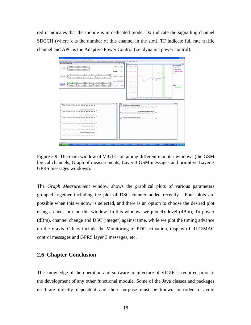
red it indicates that the mobile is in dedicated mode. Dx indicate the signalling channel
SDCCH (where x is the number of this channel in the slot), TF indicate full rate traffic
channel and APC is the Adaptive Power Control (i.e. dynamic power control).
Figure 2.9: The main window of VIGIE containing different modular windows (the GSM logical channels, Graph of measurements, Layer 3 GSM messages and primitive Layer 3 GPRS messages windows). The Graph Measurement window shows the graphical plots of various parameters
grouped together including the plot of DSC counter added recently. Four plots are
possible when this window is selected, and there is an option to choose the desired plot
using a check box on this window. In this window, we plot Rx level (dBm), Tx power
(dBm), channel change and DSC (integer) against time, while we plot the timing advance
on the x axis. Others include the Monitoring of PDP activation, display of RLC/MAC
control messages and GPRS layer 3 messages, etc.
2.6 Chapter Conclusion
The knowledge of the operation and software architecture of VIGIE is required prior to
the development of any other functional module. Some of the Java classes and packages
used are directly dependent and their purpose must be known in order to avoid

19
unnecessary code repetition and to save time. This chapter successfully gave some
background on VIGIE’s principle of operation. Other vital information can be found in
Appendices A and B.

20
CHAPTER 3 JOURNAL PAPER 3.1 Chapter Introduction In the case of a dissertation, several evaluation processes are used. First there is a
colloquium (a public defense of the work done) which is followed by an external
examination of the dissertation. Since the ultimate aim of any post-graduate work is to
contribute to A field, the acceptance of a peer-reviewed journal paper on the work done
for a dissertation can facilitate the external examination process as it shows that the work
done was subjected to a peer review process. It is furthermore a convenient way of
presenting the essence of the contribution and demonstrating that the candidate
understands the process of making knowledge available in the public domain. For this
reason the supervisors for this dissertation recommended presenting the essence of the
work by the inclusion of the journal paper published during the course of the work of
which the bulk was carried out during the nine month period while the candidate was a
visiting student at ENST Paris.
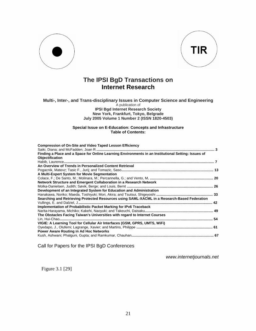
Figure 3.1 and Figure 3.2 give the front matter of the journal in which the published
paper appeared.
21
The IPSI BgD Transactions on Internet Research
Multi-, Inter-, and Trans-disciplinary Issues in Computer Science and Engineering
A publication of IPSI Bgd Internet Research Society
New York, Frankfurt, Tokyo, Belgrade July 2005 Volume 1 Number 2 (ISSN 1820-4503)
Special Issue on E-Education: Concepts and Infrastructure
Table of Contents:
Compression of On-Site and Video Taped Lesson Efficiency Saiki, Diana; and McFadden, Joan R........................................................................................................................ 3 Finding a Place and a Space for Online Learning Environments in an Institutional Setting: Issues of Objectification Habib, Laurence........................................................................................................................................................ 7 An Overview of Trends in Personalized Content Retrieval Pogacnik, Matevz; Tasic F., Jurij; and Tomazic, Saso............................................................................................. 13 A Multi-Expert System for Movie Segmentation Colace, F.; De Santo, M.; Molinara, M.; Percannella, G.; and Vento, M. ................................................................ 20 Network Structure and Emergent Collaboration in a Research Network Molka-Danielsen, Judith; Søvik, Berge; and Louis, Bernt ....................................................................................... 26 Development of an Integrated System for Education and Administration Hanakawa, Noriko; Maeda, Toshiyuki; Mori, Akira; and Tsutsui, Shigeyoshi ......................................................... 33 Searching and Retrieving Protected Resources using SAML-XACML in a Research-Based Federation Vullings, E. and Dalziel, J........................................................................................................................................ 42 Implementation of Probabilistic Packet Marking for IPv6 Traceback Narita-Harayama, Michiko; Kakehi, Naoyuki; and Takeuchi, Daisaku..................................................................... 49 The Obstacles Facing Taiwan’s Universities with regard to Internet Courses Lin, Hui-Chao........................................................................................................................................................... 54 VIGIE: A Learning Tool for Cellular Air Interfaces (GSM, GPRS, UMTS, WiFi) Oyedapo, J., Olufemi; Lagrange, Xavier; and Martins, Philippe ............................................................................. 61 Power Aware Routing in Ad Hoc Networks Kush, Ashwani; Phalguni, Gupta; and Ramkumar, Chauhan................................................................................... 67 Call for Papers for the IPSI BgD Conferences
www.internetjournals.net
Figure 3.1 [29]

22
The IPSI BgD Internet Research Society The Internet Research Society is an association of people with professional interest in the field of the Internet. All members will receive this TRANSACTIONS upon payment of the annual Society membership fee of €50 plus an annual subscription fee of €200 (air mail printed matters delivery).
Member copies of Transactions are for personal use only IPSI BGD TRANSACTIONS ON INTERNET RESEARCH
www.internetjournals.net
Figure 3.2 [29]

23
Abstract—One of the difficulties encountered in the teaching of mobile radio
networks is to present in a simple way the interaction and the sequencing of various
tasks, which must be carried out by the mobile station (MS) and the network over the
air interface. The comprehension of these processes is facilitated when they are
presented in a visual form that can be understood in real-time, when the common MS-
Network tasks such as voice call (MS oriented or MS terminated), short message
service (SMS) are going on. This paper describes the architecture of the VIGIE
(Visualisation and Interpretation of GSM/GPRS for Institutes & Ecole) software,
developed in Java to display the exchanges of these tasks between the MS and the
network. The uniqueness in the architecture of this tool is revealed in terms of its
modularity. Finally the current work done on the development of the General Packet
Radio Service (GPRS) logical screen and the Downlink Signalling Counter (DSC)
graphical screen are described
Index Terms—Air interface, GPRS, and GSM
3.2 Introduction
Between 1996 and 2000 a software tool for the teaching and visualization of Global
System for Mobile Communications (GSM) protocol over the air interface called
GSMShow was developed within the department of Information and Networks of ENST
(Ecole National Superieure des Telecommunications). This software is used on a
computer connected via a serial link to a GSM trace mobile. A trace mobile is similar to
an ordinary mobile station in every aspect and can be used on any operational network
except that it has the characteristic to send in “rough form” (a succession of bytes) the
messages exchanged between the network and its measurements and calculations. The
VIGIE: A Learning Tool for Cellular Air Interfaces (GSM, GPRS, UMTS, WiFi)
Oyedapo, J., Olufemi; Lagrange, Xavier; and Martins, Philippe

24
role of this software is to display in a convivial form the exchanges between the network
and the trace mobile. The user thus sees the exchange of these frames but from different
points of view; each point of view is what led to the development of different windows
where the user can monitor specific behaviour of the mobile to the network or vice-versa.
In 2001, the advent of GPRS led to the development of a new software tool called VIGIE.
This software was developed by ENST-Paris and ENST-Bretagne. VIGIE is a teaching
aid particularly adapted to render comprehensible, the principle of encapsulation (joint
visualization of layers 2 and 3), frequency hopping, management of timing advance (TA)
and power control, logical channels, activation of GPRS sessions and so on. It also makes
it possible to highlight the sequencing of messages for various services. This software is
developed in Java, and the aim is to make it more evolutional than its predecessor
(GSMShow). It is able to support the GSM/GPRS protocol and also to be interfaced with,
potentially any trace mobile. In the future, it will be able to support other protocols such
as Wireless Local Area Network (WLAN), Universal Mobile Telephone Service (UMTS)
or Enhanced Data rates for GSM Evolution (EDGE).
3.3 Principle of Operation
3.3.1 Review Stage
The VIGIE software is intended to be used coupled with a trace mobile, which is
connected to the computer via a serial link. The trace mobile theoretically allows the
retrieval of all signalling frames as well as frame headers of transmitted data during
communication. It also transmits information about the radio environment where it
operates and in particular reception measurements levels of signals transmitted by the
neighbouring cells.
Figure 3.3: Sequential connection of entities interacting during the use of VIGIE software
Air Interface
Raw frame
Serial Link
Frame
exchange

25
The information transmitted by the mobile on the serial link is generally divided into two
parts: the information transmitted by the mobile, which has a format that is actually
dependent on the type of trace mobile used and on the other hand the standardized frames
which are transmitted or received on the radio link. However the reception of these
frames is useful only if the user is able to understand and interpret them. This binary
format is not very convivial and does not emphasize the most significant aspects of the
radio resource procedures. VIGIE thus makes it possible to automate this decoding, to
interpret the frame contents and most importantly to have the results in such order that
will facilitate the user to understand the operation of GSM/GPRS system.
Figure 3.4: VIGIE principle of operation [5].
3.3.2 Functionalities
The VIGIE software consists of three modes of operation. The serial mode requires the
serial connection of the trace mobile to the computer. In this mode, the software stores all
the data (frames and reports) delivered by the trace mobile in real time and records them
in a temporary file. This is done to save all the data for possible future storage so as to re-
launch the saved data for analysis.

26
The file mode step-by-step allows to run the recorded traces that were saved in the serial
mode. Each time the user prompts, the message is read from the trace file; this mode is
recommended if sequence of a specific task is to be closely monitored. The fixed time
delay file mode is similar to the step by step file mode, except that the reading of the file
is done automatically at the rate of 1 second.
3.4 Software Architecture
GSMShow, which is the predecessor of VIGIE interfaces only with the trace mobiles
using Orbitel serial link protocol and as a result could not support the GPRS mobile radio
protocol. It would have been very difficult to develop and add a new screen that will
permit the display of GPRS system information.
Thus the architecture of VIGIE was conceived to be strongly evolutionary. It must be
able, via a system of drivers to adapt to the protocol used by the trace mobile to
communicate with the computer. It must also be able to present other mobile radio
protocols such as the EDGE and UMTS or the operation of WLAN systems.
The data frames are conveyed between the trace mobile and the computer via the serial
link which interfaces the trace mobile with the computer. The format of the frames on
the serial link depend on the trace mobile used, but a system of drivers makes it possible
to translate the incoming frames into a format we referred to as generic. That format can
be used by all the remaining modules within the software architecture.
The driver primarily makes it possible to group raw frames captured by the mobile into
two main groups. The information received from the network such as those transmitted
on the logical channels and the results of the measurements the mobile carried out to
report back to the network: we referred to these formats as the Frame and Report
respectively. We also further identifies Report types (idle mode or dedicated mode) and
frame type - layer 3 (L3), GSM layer 2 (L2), GPRS, and GPRS Mobility Management –
Session Management (GPRS GMM-SM). As shown in Figure 3.3, it is the generic format
that is temporarily saved, which means that it is impossible to view the raw frames

27
coming directly from the trace mobile in the step-by- step mode. Thus the appearance of
a new type of trace mobile requires only the creation of the driver that corresponds to
such trace mobile.
The generic frames are presented in the form of Java serializable objects, which makes it
possible to be recorded in a file format (in this case we used .trc extension) in order to
re-launch the saved trace when data to be observed is not in real time mode. A module we
referred to as the Interpreter makes it possible to further carry out decoding of the frames
and report.
The interpreter decodes the content of L3 frames and sort them using protocol
discriminator into Call Control (CC), Mobility Management (MM), Radio Resource
(RR), Session Management (SM) messages, Radio Link Control / Medium Access
Control (RLC/MAC) messages. The sorting of messages sent on the logical channels,
which include SACCH data, Broadcast Control Channel (BCCH) report, page report,
channel request report, Access Grant Control Channel (AGCH) report and
synchronization report are done by the interpreter.
The Dispatcher makes it possible for the decoded frames and reports in idle and
dedicated mode to be progressively distributed as required onto each window upon their
arrival. It allows us to group together the frames, reports and to display them in a manner
that can be easily understood.
The Window module represents viewing of different parameters/information as sorted by
the Dispatcher; this is the graphic user interface part of VIGIE, where the users actually
interact with the tool. A collection of windows may be considered as a module but they
are independent of each other, again the modularity of this tool is being revealed in this
aspect as a new window may be developed depending on what is intended to be displayed
to the users.

28
Figure 3.5: Simplified software architecture for VIGIE.
3.5 Software Description
On the main Graphical User Interface (GUI) window there are eight different menus that
can be activated (though more could be activated as we develop new screens). On top of
this window, just below the menus, appears a horizontal bar that displays all the activities
performed by the mobile (measurements, transmission or reception of frames). At the
leftmost base of the main window is the indicator of state, which gives the state of
connection of the trace mobile to the serial ports; this could be connected, not connected
or disconnected. Note that only the connected state is displayed when you are in the serial
mode.
Description of the windows: The Frame serial window displays all the frames that are
exchanged on the serial link in the raw format. This window is only active when you are
in the serial mode. Frames and Reports window displays the decoded frames in generic
format; this window is also active in the serial mode.
Dedicated Layer 2 and SACCH window displays all the layer 2 messages on the
dedicated channel or on the SACCH. GSM Layer 3 Message window displays the
messages of layer 3 with or without filtering. Messages that can be filtered include
BCCH System Information, Padding Paging, measurement Report, SACCH system
Information, Paging (all types) and Empty.

29
Current BTS (base transceiver station) Configurations window displays various
information of the current cell. If one of the neighbouring cells is displayed in blue, this
means that the BCCH message is being received at this frequency. In the same way
display in green indicates the reception of synchronization message. The edge of the box
indicates the state of the mobile; if displayed in blue, the mobile is in idle mode while red
indicates that the mobile is in active mode. When all the borders of boxes are displayed in
red it indicates that the mobile is in dedicated mode. Dx indicate the signalling channel
SDCCH (where x is the number of this channel in the slot), TF indicate full rate traffic
channel and APC is the adaptive power control (i.e. dynamic power control).
The Graph Measurement window shows the graphical plots of various parameters we
decided to group together including the plot of DSC counter we added recently. Four
plots are possible when this window is selected, and there is an option to choose the
desired plot using a check box on this window. In this window, we plot Rx level (dBm),
Tx power (dBm), channel change and DSC (integer) against time, while we plot the
timing advance on the x axis.
Figure 3.6: VIGIE main window containing several windows (including the Graph Measure window that contains DSC).
30
3.6 Developing the GPRS Logical Screen
3.6.1 Integrating the DSC into the Graph Measurement Screen
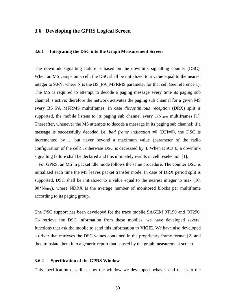
The downlink signalling failure is based on the downlink signalling counter (DSC).
When an MS camps on a cell, the DSC shall be initialized to a value equal to the nearest
integer to 90/N; where N is the BS_PA_MFRMS parameter for that cell (see reference 1).
The MS is required to attempt to decode a paging message every time its paging sub
channel is active; therefore the network activates the paging sub channel for a given MS
every BS_PA_MFRMS multiframes. In case discontinuous reception (DRX) split is
supported, the mobile listens to its paging sub channel every 1/NDRX multiframes [1].
Thereafter, whenever the MS attempts to decode a message in its paging sub channel; if a
message is successfully decoded i.e. bad frame indication =0 (BFI=0), the DSC is
incremented by 1, but never beyond a maximum value (parameter of the radio
configuration of the cell) , otherwise DSC is decreased by 4. When DSC≤ 0, a downlink
signalling failure shall be declared and this ultimately results in cell reselection [1].
For GPRS, an MS in packet idle mode follows the same procedure. The counter DSC is
initialized each time the MS leaves packet transfer mode. In case of DRX period split is
supported, DSC shall be initialized to a value equal to the nearest integer to max (10,
90*NDRX), where NDRX is the average number of monitored blocks per multiframe
according to its paging group.
The DSC support has been developed for the trace mobile SAGEM 0T190 and OT290.
To retrieve the DSC information from these mobiles, we have developed several
functions that ask the mobile to send this information to VIGIE. We have also developed
a driver that retrieves the DSC values contained in the proprietary frame format [2] and
then translate them into a generic report that is used by the graph measurement screen.
3.6.2 Specification of the GPRS Window
This specification describes how the window we developed behaves and reacts to the
31
decoding of each type of RLC/MAC PDU (packet data unit). This window is made up
of labels, text fields as well as graphics. The encoding of RLC/MAC blocks was defined
by the means of concrete syntax notation no 1 (CSN.1). The CSN.1 is a descriptive
language for digital message encoding, which enables the description of the structure of
message down to the bit level, and is particularly useful to describe bit-efficient encoding
[4]. The RLC/MAC specification uses CSN.1 to define the whole of valid blocks which
can be exchanged between the MS and the BTS on the logical channels specific to the
GPRS [3].
The Temporary block flow (TBF) concept: the TBF is a logical connection between the
RR entity at the MS side and the RR entity at the network side to support the
unidirectional transfer of logical link control (LLC) protocol data units over packet data
channel (PDCH) [11]. The TBF exists as much as the transmitter has in memory the data
to transmit, which can correspond to the broadcast of several LLC packets [11]. There are
two types of TBF, the downlink TBF is one in which data flow goes from the network to
the mobile. The mobile returns acknowledgements and measurement to the network.
Here the network sends message of pre-allocation to the MS specifying which blocks to
decode in the slots allocated to it; some of these blocks may not be intended for this MS,
but can carry data for another MS. The final recipient of the block is designated by the
temporary flow identifier (TFI) field included in the block and usually the MS will find
in one of these blocks an allocation for the uplink that will specify which block to
transmit its acknowledgement and measurements.
In the uplink TBF, principal data flow goes from the MS to the network and it is the
network that manages the allocation of the resources on the uplink (it manages the
scheduling between mobiles). The mobile thus listens to “orders” from the network on
the downlink to know which of the slots it can transmit on. These “orders” are identified
by the TFI; it must also listen on the downlink for the acknowledgement of the packets it
transmits. There are two possible allocations on the uplink – dynamic allocation and
static allocation.
32
In dynamic allocation, MS receives an identifier called Uplink State Flag (USF) by slot
which it manages and then listens on the downlink. When it locates its identifier in the
downlink block, it knows it can transmit starting from the following block. In static
allocation, MS receives a message indicating the blocks in which it will be able to
transmit for certain period. This allocation is limited to 128 blocks but can be repeated for
another period; the mobile only knows if the allocation is renewed during
acknowledgement. Thus TBF implies transmission in two directions, which could be
uplink or downlink. It is possible for a mobile to have two TFIs, a TFI uplink and a TFI
downlink, which shows that these two aspects are independent, hence there, could be four
states: TBF not in progress, UPLINK TBF is in progress, DOWNLINK TBF is in
progress and UPLINK TBF and DOWNLINK TBF are in progress.
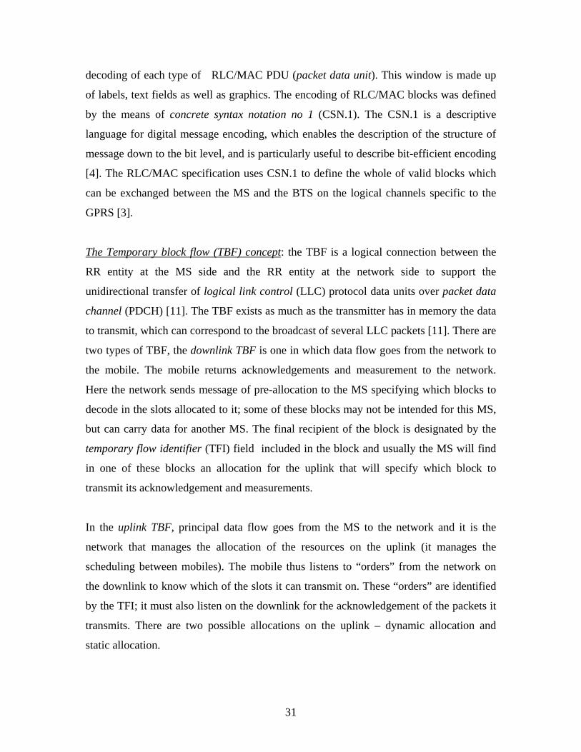
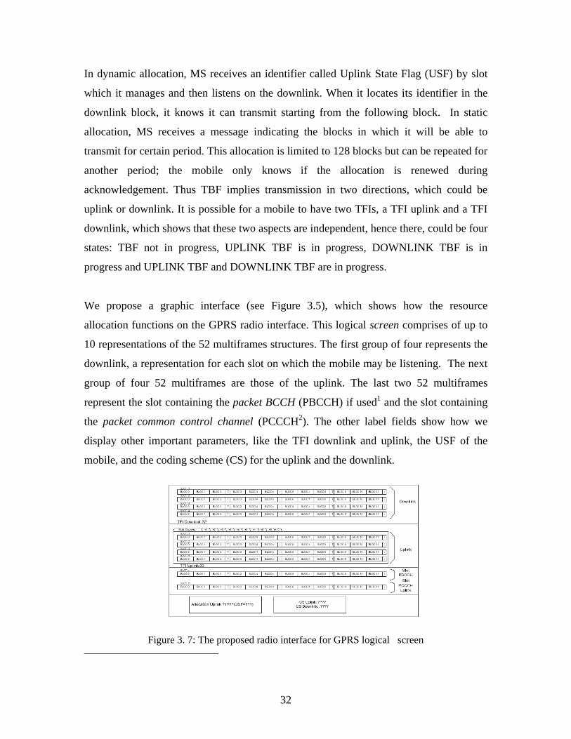
We propose a graphic interface (see Figure 3.5), which shows how the resource
allocation functions on the GPRS radio interface. This logical screen comprises of up to
10 representations of the 52 multiframes structures. The first group of four represents the
downlink, a representation for each slot on which the mobile may be listening. The next
group of four 52 multiframes are those of the uplink. The last two 52 multiframes
represent the slot containing the packet BCCH (PBCCH) if used1 and the slot containing
the packet common control channel (PCCCH2). The other label fields show how we
display other important parameters, like the TFI downlink and uplink, the USF of the
mobile, and the coding scheme (CS) for the uplink and the downlink.
Figure 3. 7: The proposed radio interface for GPRS logical screen

33
3.6.3 Decoding of the Blocks
The specification of how the proposed interfaces must react to the reception of
RLC/MAC blocks is based on their definition in CSN.1. As we have described above, we
wrote the program from the syntax of CSN.1 to create a procedure which is able to
determine if the bit strings subjected to it (procedure) belongs to the set of bit strings
defined by the syntax and which, if necessary, can isolate each sub string named in this
syntax. We thus specify the reactions of our program according to the values of these sub
strings; and if these sub strings would not be present, the program should not have any
reaction relative to its value except if explicitly indicated.
3.7 Conclusion
GSM has evolved over the years, upon which advanced systems such as GPRS, EDGE
and UMTS are based. To understand these advanced systems, however, a good
understanding of the GSM system is necessary. We have proposed and developed
simplified GUIs that will allow the users monitor and understand the sequences of a
various tasks between the MS and the network over the air interface. We finally
demonstrated the modularity in our software architecture by adding another window - the
GPRS radio resources allocation window.
3.8 References [1] Third Generation Partnership Project (3GPP) Technical Specification 05.08,
V6.9.0, Technical Specification Group GERAN ;Digital cellular telecommunications system (Phase 2+) ; Radio subsystem link control (Release 1997), 2000.09, pp.15
[2] Serial link interface Specification for test tools, protocol Version V3.11, Sagem
document, 15 April, 2004. [3] De Wulf, Martin., Lagrange, Xavier., “Specification of the logical channel screen
of Vigie software (GPRS Show)”, ENST Bretagne, version 1.0, May.2002 .

34
[4] Mouly, Michel., “CSN.1 Specification (version 2.0),” [5] Dailly, Nicolas., “ Développement en Java d’une Plate-forme Pédagogique
GSM/GPRS”, MSc. Thesis, Dept. INFRES, ENST-Paris, June.2003. [6] 3GPP Technical Specification, 03.60, Group Services and System Aspects ;
General Packet Radio Service (GPRS) ; Service description ; Stage 2. Version 6.11.0, Release 1997.
[7] 04.07 3GPP Technical Specification, Version 6.5.1 Release 1997, Mobile Radio
Interface Signaling Layer 3;, General Aspects. [8] 04.08. 3GPP Technical Specification, Version 6.21.1 Release 1997, Mobile Radio
Interface Layer 3 Specifications. [9] 04.60. 3GPP Technical Specification, Version 6.14.0 Release 1997, Radio Access
Network; General Packet Radio Service (GPRS); Mobile Station (MS) – Base Station System (BSS) Interface; Radio Link Control/Medium Access Control (RLC/MAC) Protocol.
[10] 05.05. 3GPP Technical Specification, Version 6.8.0, Release 1997, Radio
Transmission and Reception. [11] Seurre, Emmanuel., Savelli, Patrick., Pietri, Pierre-Jean.,“GPRS for Mobile
Internet”, Artech House Publisher, 2003. [12] Lagrange, Xavier., Godlewski, Philippe., Tabbane, Sami., “Réseaux GSM (GSM
Networks)”, 5th Edition, Hermes Science, 2000. [13] Favre, Julien., Foulon, Julien., Lagrange, Xavier., “Creation of the Generic File
Format for the Storage of GSM and GPRS traces for VIGIE Application”, 13.February.2003.
[14] Mouly, M., Pautet, M.B., “The GSM System for Mobile Communications”, Cell
& Sys., Paris, 2000. [15] Heinne, Gunnar., “GSM Networks:Protocols, Terminology, and Implementation”,
Artech House Publishers, Norwood, MA. 1999.

35
[16] Eberspaecher, Jorg., Vogel, Hans-Jorg., “GSM Switching, Services and Protocols”, 2nd Edition, John Wiley & Sons.
1 If the PBCCH is used, only 3 representation of the DOWNLINK multiframe can be used, since PBCCH occupies a DOWNLINK slot, this slot in addition to PBCCH can also transport data for the mobile. 2
Same remark as for the PBCCH slot, but for the UPLINK multiframe.

36
CHAPTER 4
DEVELOPMENT, RESULTS AND CONCLUSION
4.1 Chapter Introduction
This chapter focuses on the work done in this project in terms of the development
(programming in Java), with special attention given to the development of the GPRS
logical screen and DSC functionalities. The programming exercise was preceded by the
manual decoding of GSM and GPRS messages on the air interface. This served as a
debugging exercise to validate and test previously developed modules and verified if they
conformed to the 3GPP TS standards. Several 3GPP TS documents were used to assist in
this decoding exercise. The allocation of radio resources in a GPRS network is presented
with the automation of each of the 12 possible blocks on per slot basis and the DSC
function.
4.2 The Concrete Syntax Notation (CSN). 1
The encoding of RLC/MAC blocks was defined by means of CSN.1 notation created by
Michel Mouly [14]. CSN.1 is a notation intended to describe the binary encoding of a
protocol. The core of this notation more or less inherits, directly the Backus-Naur-Form
(BNF) notation used in particular by the American National Standards Institute (ANSI) to
define the syntax of the C language. The fundamental difference is that the smallest
handled unit is the bit in CSN.1 and a character in the BNF.
CSN.1 makes it possible to define sets of strings of bits. The RLC/MAC specification
uses CSN.1 to define the whole of the valid blocks which can be exchanged between the
MS and the BTS on the logical channels specific to GPRS.

37
Moreover CSN.1 makes it possible to give names to parts of strings of bits correctly
encoded. This makes it possible to easily define the semantic of chains of bits, i.e. the
interpretation of the message.
Figure 4.1: Objects in Packet System Information Type 3 message defined in CSN.1 Figure 4.1 is an example of definition in CSN.1 extracted from packet system
information type 3 (PSI3) message [11]. It is, in fact the definition of the <Cell
Selection struct > object. It can be seen that for each of its fields, a name is specified,
for example there exists 6 bits of BSIC fields. The sign ⏐ represents an alternative.
Consequently a field such as < HCS struct > is optional, it is present if the bit which
precedes its location is a 1. From this example, one can see the fundamental
difference between CSN.1 and the traditional description of packets format (usually
in the forms of grids with a box by bit description). In CSN.1 it is not known where a
field will be before going through all the part of the chains preceding it. CSN.1
induces a decoding of the packets by sequential reading. On the other hand, it allows
very efficient use of the available bits. The description of a protocol that is as
complex as RLC/MAC would not have been possible without such a notation.

38
It can be seen in this example that the concept of set of bit strings is central to this
notation. Object < SI13 PBCCH Location struct > is a set of bit strings which is used
to build more complex object < Cell Selection struct > which is a set of bit strings,
the complex sets being constructed from simpler sets, down to the bit level.
CSN 1 is compilable, which means that it is possible to create a compiler which is
based on the CSN.1 syntax. This will create a program that will be able determine if
chains of bits which one subjects to it (program) belongs to the set of bit strings (any
object described by the notation is a set of bit string), and if necessary, can isolate
each sub-string named in this syntax. This is the principal interest of this notation.
For an extensive description of CSN.1 see [14]. The decoding of RLC/MAC
messages in VIGIE for debugging purposes and the writing of code in Java was done
according to the CSN.1 syntax.
4.3 Coding the DSC Window and the GPRS Resource Allocation
Window
4.3.1 Writing the Java Code for the DSC Window
The Graphe de Mesures (Graph Measurements) window was developed with the DSC
function. Some Java code was reused from different classes, and a few classes were
modified to develop the user interface.
Initially it was impossible to retrieve the DSC values (current and maximum DSC
values) from the trace messages sent by the MS to the PC side. This was later confirmed
that the trace mobile does not send the QoS trace message to which the DSC values
belong.

39
When the code in the Java class that implements the driver for the trace mobile OT 190
was verified, it was discovered that no code wase written that will request the trace
mobile to send the QoS indicator trace messages to which the DSC counter belong and
hence the trace mobile was requested to send the QoS trace messages by a command
from the PC or specifically the DSC QoS information. The following is a sequence of
steps involved in extracting the DSC values:
(1) In the Java class MobileOT190MGPRS.java, a method
(sendStartOTRMessage( )) was written, to describe the building of frame that
the command used to activate the mobile to start sending the QoS indicator
message. Another method (sendStopOTRMessage( )) was used to indicate the
mobile to stop.
sendStopQoSCommand( ) { byte[] packet = new byte[6]; packet[0]=0x20 packet[1]=0x1F; // packet[2]=0x00; // packet[3]=0x00; packet[4]=0x00; packet[5]=0x04; sendOTRMessages(packet); sendStopQoSCommand() { byte[] packet=new byte[6]; packet[0]=0x20; packet[1]=0x1F; packet[2]=0x00; packet[3]=0x00; packet[4]=0x00; packet[5]=0x00; sendOTRMessages(packet);
(2) Method sendOTRMessage (byte [] buffer) makes it possible to send the
command in the predefined OTR format to the mobile (see Figure C.1).

40
(3) The class SagemOT190MGPRSDecoder.java, analyses the information (trace)
messages in generic format. This is done by a method, which processes the
header by checking the type of the trace message sent by the mobile, the
Category that are reply message for QoS and trace message for QoS:
processHeader( );
switch (_Type) { ……….. …………. case 0x01: switch(_Category) { case 0x01: break; case 0x03: _emprint = (Empreinte)qosim_decoder.decode(trame_content, _SubType); break; } break;
(4) Finally a new class was created (SagemOT190MGPRSQoSIM_Decoder.java)
for the decoding of DSC QoS counter. If the type of message is identified as
the “QoS information message” (0x01), and the Category is identified as
“reply message” for QoS (0x01) and “trace message” (0x03), it then proceed
to check the content of the DSC counter trace message, that has a format
shown in Appendix C Figure C.6.
First we checked if the field length matches “0x02” on the 1st byte (note, this
is done by checking the whole byte) if it is true, we proceed to look at the
content of the 2nd and 3rd byte that are maximum DSC and current DSC values
respectively. These values are directed to be printed on the DOS command
line. The values are DSC_max =18, DSC_current=18. These values are only
sent in the idle mode, once the mobile is in the dedicated mode the values
changes to that of RTL.

41
At the end of the coding, the serial frames were decoded to ascertain that the code written
were correct the result of this coding is presented in section 4.4. For the full lines of code
see class SagemOT190M_QoSIM_Decode.java in Appendix E.
4.3.2 The Java Code for the GPRS Resource Allocation Window
The coding of the GPRS Resource Allocation window was done in two steps. Firstly,
the GUI was developed to display all the necessary information needed during uplink
and downlink TBF at the RR entities on the MS side and the BSS side on the air
interface, and secondly the behaviour of the blocks (i.e. how the blocks respond to the
decoded frames and data) were coded.
In developing the GUI for the GPRS Resource Allocation window, different methods
were written for the class named GUIGPRSRadioAlloca.java. This class extends the
class VigieFrame.java in order to conform to the appearance of the remaining
windows in VIGIE (though the dimension of the window was changed). This class
also implements TrameListener.java.
All the methods written within the class GUIGPRSRadioAlloca.java are summarized
below. The full code can be found Appendix E.
Method 1: init3BlocksPlusSlot( )
This method places three blocks at coordinate (x, y) followed by T and i using a
control statement. These are labels whose borders are etched using EtchedBorder.

42
Method 2: initMultiframe( )
Within this method, method 1 was invoked four times again using, control statements
to control the positioning of the T and i slots within this multiframe. This is the
representation of one 52 multiframe.
Method 3: initPanel4Multiframe( )
Within this method, Method 2 was invoked four times this completes the code that
forms the four 52-multiframes for the downlink on a per slot representation. Each 52-
multiframe is labelled from slot 1 – slot 4.
Method 4 : initTabbedPaneUplink( )
Here a loop of ten was created and on each loop method 3 is called and each is placed
in a tabbed pane; this creates the representation by slot of four, each 52-multiframe
structure in ten tabbed panes. This feature is not activated in this project as it is
designed for static allocation on the uplink.
In the constructor of this class ( i.e. GUIGPRSRadioAlloca( )), methods 3 and 4 were
called. For method 3, its argument JLabel[][] indicated that the values it took in was
instantiated as [4][12]. The idea is to be able to reach each of the labels used for the
representation of each block (on each 52-multiframe) in a logical manner. Thus the
first block on the first 52-multiframe is accessed as [0][0], [0][1] and so on.
Similarly, the uplink was instantiated to [4][120] to be able to reach each block in a
logical manner. For the PBCCH and the PCCCH slot, method 3 was invoked with the
argument JLabel[][] labels instantiated as PBCCHlabel = new JLabel [12] and
PCCCHlabel = new JLabel [12] respectively.
The last panel consists of JLabel objects for each of the information displayed. The
GUI window for the GPRS Radio Resource Allocation is shown in section 4.4, Figure
4.6.

43
Coding the Behaviour of the Block and the Information fields
In coding this window, the modular architecture of VIGIE makes it easier to integrate the
class intended for this part of VIGIE. Every class that wants to listen to the transmission
of frames (TrameEvent) and report (RapportEvent) must implement the methods
addTrameListener and addRapportListener from the Dispatcher. These methods are
invoked inside the Java class GUImain.java for all the windows, which takes in the object
of the window concerned. The GPRS radio resource allocation window makes use of the
method, addTrameListener in the GUImain.java as:
_disp.addTrameListener(_winAllocGPRS);
The Dispatcher sends all the frame events that are required to the developed window
(GUGPRSRadioAlloc). And as these frames are sent they have to be processed by this
window, hence we specified what needed to be done to these frames. This led to the
writing of a method processTrameEvent() inside this class, which is unique to this class
in terms of processing these frames as they arrive.
Information Fields – CS, TFI uplink, TFI downlink, USF and CS
First, all the information fields displayed are represented by JLabel- TFI Downlink, TFI
Uplink, USF, CS uplink, CS Downlink. The methods that were used in decoding the
RLC/MAC data for uplink and downlink were reused (extraitBit(), extraitBits(), and
extraitBitCSN()). They were all used to extract a bit in a specified octet and bits in a
specified octet respectively. Inside the processTrameEvent method these methods were
invoked passing in the required arguments that will extract the required values for the
TFIs and the USF. Refer to Appendix E for the code listing.

44
In extracting all the information fields, the following were done in succession of steps
(1) First test if the message is complete and not a repeated message by using the
following syntax:
(trame_courante_decodee.getIncomplet()= =false&&
frame_courante_decodee.getRepetition() = =false )
(2) Next check if the message subType is GPRS and exclude message subType of
GMM/SM :
(sub_type_lu = = 0x1|| sub_type_lu = =0x4)
(3) Then extract the payload for the GPRS RLC/MAC data block, and if
payload = =0,
Start by checking if random access is being performed and test if the data
transmission is on the DOWNLINK GSM 04.60 section 10.2.1[11].
Proceed and make, payload = extraitBits(contenu[0],7,8)
We further decode the TFI in the downlink and the USF. Otherwise if the
transmission is in the UPLINK we decode the TFI in the uplink GSM 04.60
section 10.2.2 [11].
Else if payload = = 1,
The frames are processed to obtain the CS, a new method is re-written, method
decodeCS(), checks the decoded frames from TramDecodee in a CSN.1 format.
Again, check if the frame is complete and not repeated, checked if random access
is being performed, and if the transmission is done in the downlink direction, we
decoded the CS if all these conditions were satisfied according to GSM 04.60
section 10.3.1 [11].

45
Coding of the Blocks
The PBCCH and the PCCCH were not present in the SFR network (French cellular
network) under observation and hence one could not make use of the packet system
information messages sent on PBCCH or PACCH that could be used to perform the
decoding of the blocks.
We rely on the packet uplink and packet downlink assignments to decode these blocks
and display them on the GPRS radio allocation window as developed. The packet uplink
and packet downlink assignments are sent either on the PCCCH or PACCH by the
network to the mobile on uplink and downlink resources respectively.
On the packet downlink assignment message, we decode the
TIMESLOT_ALLOCATION IE, which is a field of 8 bits. Bit 8 indicates the status of
timeslot 0, while bit 7 indicates timeslot 1, and so on. If the bit at any position is 1, that
timeslot is assigned for the resource on the downlink; and if 0, the timeslot is not
assigned, see GSM 04.60 section 11.2.7 and section 12.18 [11]. The excerpt below is a
part of packet downlink assignment message content showing the timeslot allocation
object in red colour [11].
< Packet Downlink Assignment message content > ::= < PAGE_MODE : bit (2) > { 0 | 1 <PERSISTENCE_LEVEL : bit (4) > * 4 } { { 0 < Global TFI : < Global TFI IE > > | 10 < TLLI : bit (32) > } { 0 -- Message escape { < MAC_MODE : bit (2) > < RLC_MODE : bit (1) > < CONTROL_ACK : bit (1) > < TIMESLOT_ALLOCATION : bit (8) > < Packet Timing Advance : < Packet Timing Advance IE > > On the packet uplink assignment message side, the < Dynamic Allocation struc > ::= and
the Timeslot Allocation were decoded, which permits us to know which timeslot(s) is
dynamically assigned for the MS on the downlink, we further decode each of these
timeslot(s) to obtain the USF. If the USF is equal to that of the mobile obtained in the
previous coding of the USF, then that timeslot(s) is allocated for the MS on the uplink.

46
See GSM 04.60 section 11.2.29 [11], the excerpt below is a part of the <Dynamic
Allocation struct >. The timeslot allocation is shown in red colour.
<Dynamic Allocation struct > ::= < Extended Dynamic Allocation : bit (1) > { 0 | 1 < P0 : bit (4) > < PR_MODE : bit (1) > } < USF_GRANULARITY : bit (1) > { 0 | 1 < UPLINK_TFI_ASSIGNMENT : bit (5) > } { 0 | 1 < RLC_DATA_BLOCKS_GRANTED : bit (8) > } { 0 | 1 < TBF Starting Time : < Starting Frame Number Description IE > > } { 0 -- Timeslot Allocation { 0 | 1 < USF_TN0 : bit (3) > } { 0 | 1 < USF_TN1 : bit (3) > } { 0 | 1 < USF_TN2 : bit (3) > } { 0 | 1 < USF_TN3 : bit (3) > } { 0 | 1 < USF_TN4 : bit (3) > } { 0 | 1 < USF_TN5 : bit (3) > } { 0 | 1 < USF_TN6 : bit (3) > } { 0 | 1 < USF_TN7 : bit (3) > } | 1 -- Timeslot Allocation with Power Control Parameters We further verified the above exercise by further decoding the information message field
for MAC information trace messages. Here we decode the information in the 2nd and 3rd
byte (Figure C.7 in Appendix C) of this message and test each bit of each byte the
decoding is similar to the above procedure in section 4.3.1:
If for instance the downlink timeslot allocation is set to”00111000”, it means that
Timeslot 2,3 and 4 are used simultaneously by the mobile station (the timeslots are
contiguous).
To identify the block on which this timeslot is allocated, we locate the frame number
(FN) the on which MAC information is sent. Having obtained this FN we perform a
simple modulo 52 on the FN to get the block number that will be colourized and activated
on the GUI.
A block displayed in GREEN means that such block is reserved for the MS for future use
(reserved for the uplink) and MS shall transmit on this/these block(s), while the block(s)
displayed in RED means MS has just received a message (on the downlink) on this block.

47
On the GUI, note that we have only representation of 4 slots (which of course is the
maximum number of slots available to GPRS); it is however intended to accommodate all
the 8 possible timeslots that could be allocated by displaying the corresponding timeslot
number on the JLabel that was created for the timeslots. In this case timeslot 1 would be
used for timeslot 5 and timeslot 2 for timeslot 6 and so on. The results are shown in the
next chapter. For the full code listing see GUIGPRSRadioAlloca.java in Appendix E.
Figure 4.2 and 4.3 show the DSC functionality before and after integration into the
VIGIE main window. This is done within the Java class GUIMain.java.
Figure 4.2: The “Graph Measurement” window before development
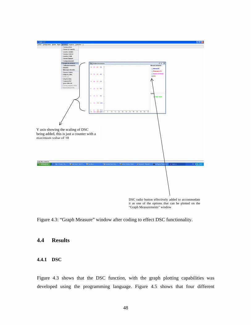
48
Figure 4.3: “Graph Measure” window after coding to effect DSC functionality.
4.4 Results
4.4.1 DSC
Figure 4.3 shows that the DSC function, with the graph plotting capabilities was
developed using the programming language. Figure 4.5 shows that four different
DSC radio button effectively added to accommodate it as one of the options that can be plotted on the “Graph Measurements” window
Y axis showing the scaling of DSC being added, this is just a counter with a maximum value of 18

49
functions can be plotted against time namely the receiver level (power in dBm),
transmission power (of mobile in dBm), timing advance (in bits) and the DSC (in
integer).
For a desired function to be plotted on this graph, the checkbox adjacent to such function
needs to be checked as shown in Figure 4.3 above. The DSC function in this case could
not be plotted due to the behaviour of the trace mobile. The trace MS sends the current
DSC value only if this value changes and the graph plotting function is a listener which
only plots (using drawLine ( ) Java method) when there are two consecutive points to
plot.
However, to prove that the DSC values are being extracted from the MS, they (DSC
values) are queried to be displayed on the command line as shown in Figure 4.4.
Figure 4.4: Display of the current and maximum DSC values on the DOS command window when MS is in communication mode.
Maximum and current DSC values displayed on the DOS command line

50
Figure 4.5: Graph Measure Window, incorporating the DSC plot.
4.4.2 GPRS Logical Screen
The user interface developed using Java shows the specification of the GPRS air interface
in a block of 12 which is made up of 52-multiframes including 4 frames for the PTCCH
and idle frames, as in Figure 4.6
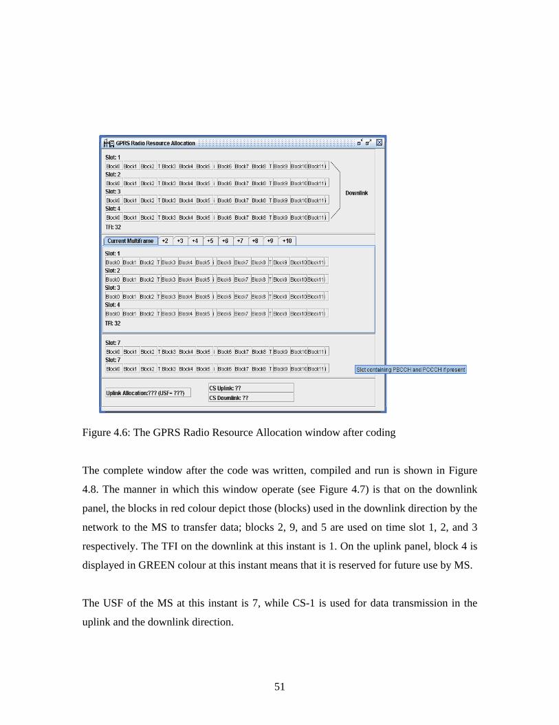
51
Figure 4.6: The GPRS Radio Resource Allocation window after coding
The complete window after the code was written, compiled and run is shown in Figure
4.8. The manner in which this window operate (see Figure 4.7) is that on the downlink
panel, the blocks in red colour depict those (blocks) used in the downlink direction by the
network to the MS to transfer data; blocks 2, 9, and 5 are used on time slot 1, 2, and 3
respectively. The TFI on the downlink at this instant is 1. On the uplink panel, block 4 is
displayed in GREEN colour at this instant means that it is reserved for future use by MS.
The USF of the MS at this instant is 7, while CS-1 is used for data transmission in the
uplink and the downlink direction.

52
Figure 4.7: The GPRS radio resources Allocation Window.
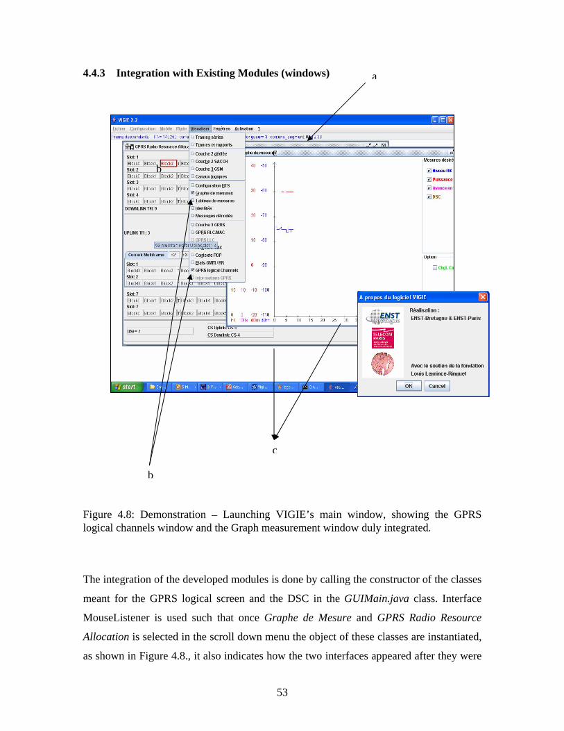
53
4.4.3 Integration with Existing Modules (windows) Figure 4.8: Demonstration – Launching VIGIE’s main window, showing the GPRS logical channels window and the Graph measurement window duly integrated.
The integration of the developed modules is done by calling the constructor of the classes
meant for the GPRS logical screen and the DSC in the GUIMain.java class. Interface
MouseListener is used such that once Graphe de Mesure and GPRS Radio Resource
Allocation is selected in the scroll down menu the object of these classes are instantiated,
as shown in Figure 4.8., it also indicates how the two interfaces appeared after they were
a
cb
b
c
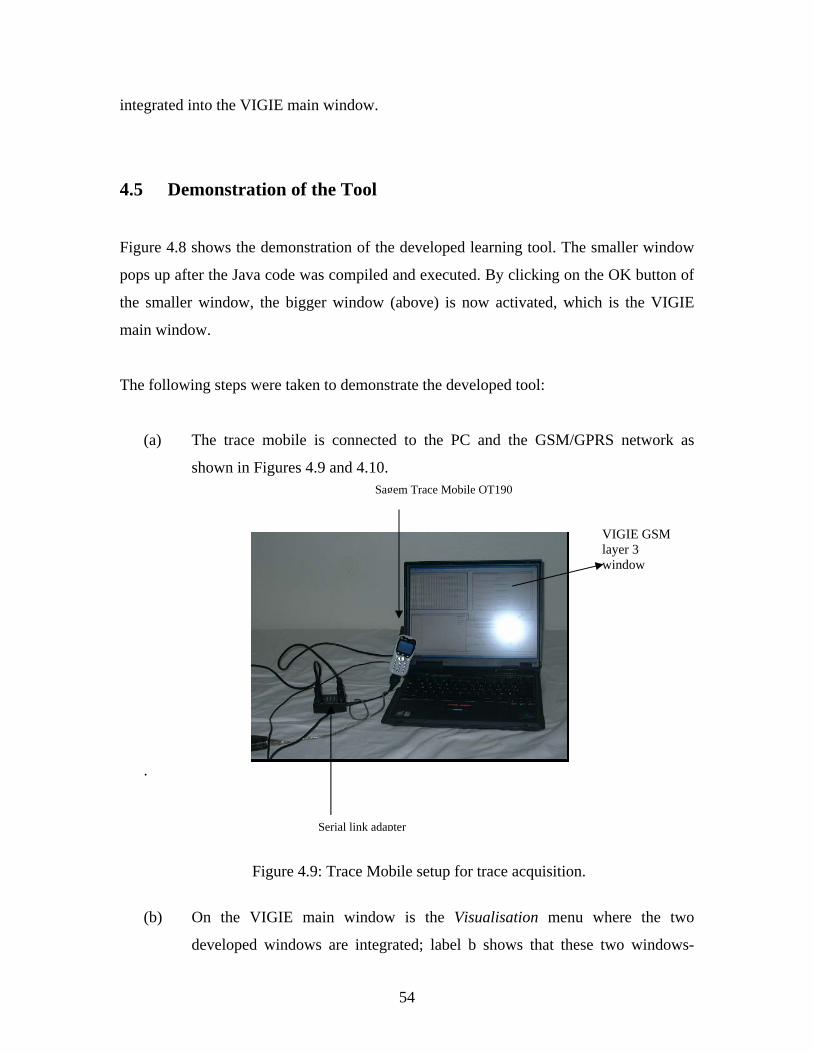
54
integrated into the VIGIE main window.
4.5 Demonstration of the Tool
Figure 4.8 shows the demonstration of the developed learning tool. The smaller window
pops up after the Java code was compiled and executed. By clicking on the OK button of
the smaller window, the bigger window (above) is now activated, which is the VIGIE
main window.
The following steps were taken to demonstrate the developed tool:
(a) The trace mobile is connected to the PC and the GSM/GPRS network as
shown in Figures 4.9 and 4.10.
.
Figure 4.9: Trace Mobile setup for trace acquisition.
(b) On the VIGIE main window is the Visualisation menu where the two
developed windows are integrated; label b shows that these two windows-
VIGIE GSM layer 3 window
Serial link adapter
Sagem Trace Mobile OT190

55
GPRS logical screen and Graphe de mesure (Graph measure) are selected and
displayed. It is possible to display other windows as seen on the Visualisation
menu.
Figure 4.10: Trace Mobile setup for trace acquisition (rear view)
(c) Setup the trace mobile with the correct data parameters as in [28]
(d) Configure the trace mobile as a modem on the Microsoft windows control
panel, using it as a standard 28800 bps Modem on COM1 of the PC and set
the port speed to 57600.
(e) On the Activation menu of VIGIE choose launch
(f) With the “Niveau Rx” and DSC boxes checked, after step (e) the plot of
power level received by the trace MS is plotted against time to show the
concept of power management in the MS. The plot of the DSC will not be
plotted for the reason previously stated. This however can be used to educate
the user, the concept of power management when a voice call is made or
during reception.
Serial link 2 for traces
Serial link 1 for data
56
(g) With the configuration performed in step (d), in the control panel right click
the new connection icon and choose connect; this sets up the PDP context
activation by connecting the trace mobile to the GPRS network (GGSN).
(h) At this instant you can see the panel labelled a (in Figure 4.8 above) showing
the frame content of the messages sent in the uplink or downlink direction, the
frame number (FN), logical channel used, and the length of the segment
transmitted. Again observing this panel, GSM L3 and GPRS L3 windows, the
user can study the types of messages exchanged between the MS and the
GSM/GPRS network and the logical channels that carry these messages.
(i) Using Microsoft internet explorer, open a webpage and observe the GPRS
resource allocation window as shown above. You will notice that each time a
TBF is established the TFI changes in each case which indicate that the
different TFI identified different TBFs. You can monitor also which block(s)
is used for data transfer in the uplink and downlink and on which time slot;
this window will give you the understanding of which RR entities that are
allocated by the network to the MS during TBFs.
4.6 Future Work
Due to modularity of VIGIE especially at the Drivers layer (lower layers) and the
Windows layer (upper layers), it will be possible in the future to develop user
interfaces/logical screens for WiFi and advanced cellular system like UMTS. Presently a
function is being developed to have the traces sent to VIGIE converted into a text file.

57
4.7 Final Conclusion
The user interfaces for the GPRS logical screen and the DSC functionality have been
developed for the Sagem trace mobiles OT 190 and OT 290. The work done in term of
code writing is at the lower and the upper layers of VIGIE (driver and window
respectively).
GSM has evolved over the years, upon which advanced system such as GPRS, EDGE,
and UMTS are based. To understand these advanced systems, a good understanding of
the GSM/GPRS system is necessary.
Having developed the GPRS resource allocation window, the procedures for the
establishment of Uplink and Downlink TBFs can be studied during packet transfer
between the MS and the GPRS network. The sequence of protocol exchanges can be
monitored in real-time; ultimately having access to the frame content sent on Layer 3 on
the air interfaces, including RLC/MAC control messages content. With the DSC function
developed it is possible to visually monitor when the MS declares a handover.
This work has contributed towards the alleviation of the difficulties encountered in the
teaching of mobile network protocols and architectures by presenting the processes
involved in visual form and in real-time (GSM TS standard (3GPP)) in way that can be
easily comprehended by the users.

58
REFERENCES [1] Available [online] http://www.journaldunet.com/0406/040617zz_umts.shtml Access 17/01/2005. [2] Gunnar Heine, 1999, GSM Networks: Protocols, Terminology, and
Implementation, Artech House Publishers, Norwood, MA. [3] Emmanuel Seur, Patric Savelli, Pierre-Jean Pietri, 2003, GPRS for Mobile
Internet, Artech House Publishers, Norwood, Michigan. [4] Usha Communications Technology, June 2000, GPRS whitepaper.
Available [online] http://www.mobilein.com/GPRS.pdf Access 25/01/2005. [5] Hakon Gudding, 2000, Capacity Analysis of GPRS (Revised Edition of
Master Thesis), Department of Electrical Engineering and Telecommunications, Norwegian University of Science & Technology, Norway.
. [6] Yi-Bing Lin, Herman C.H. Rao, Imrich Chlamtac, 2001, General Packet
Radio Service (GPRS): architecture, interfaces, and deployment, Wireless Communication and Mobile Computing Magazine, John Willey & Sons, USA.
[7] Jorma Kilpi, 2004, Spectroscopy of the Um Iterface of GPRS/GSM,
COST/FIT Seminar, Otaniemi, Micronova, Finland. Available [online] http://keskus.hut.fi/tutkimus/cost279/seminaari2004/kilpiCOSTFIT.pdf Access 10/11/2005.
[8] 3rd Generation Partnership Project (3GPP), 2001, GSM TS 23.122: NAS
Functions Related to Mobile Stations (MS) in idle mode, Version 4.1.0 Release 4, 3GPP, Sophia Antipolis, France.
[9] Ericsson AB, 2003, White paper on EDGE- Introduction of high-speed
data in GSM/GPRS Network, Sweden. Available[online] http://www.ericsson.com/technology/whitepapers/edge_wp_technical.pdf
Access 02/01/2005.

59
[10] 3rd Generation Partnership Project, 2002, GSM TS 03.60: Group Services and System Aspects (GPRS) - Service description, Stage 2 Version 6.11.0 Release1997, 3GPP, Sophia Antipolis, France.
[11] 3rd Generation Partnership Project, 2001, GSM TS 04.60: Radio Access
Network; General Packet Radio Service (GPRS); Mobile Station (MS) – Base Station System (BSS) Interface; Radio Link Control/Medium Access Control (RLC/MAC) Protocol, Version 7.9.0 Release 1998, 3GPP, Sophia Antipolis, France.
[12] Sagem SA, 2004, Serial Link Trace Interface Specification for Test Tools
(Protocol Version V3.11, Sagem SA confidential, France.
[13] 3rd Generation Partnership Project, 2000, GSM TS 05.08: Radio Subsystem Link Control Version 6.9.0 Release 1997, 3GPP, Sophia Antipolis, France.
[14] Michel Mouly, 2000, CSN.1 Specification Version 2.0, Cell & Sys
publishers, France. [15] 3rd Generation Partnership Project, 2002, GSM TS 03.22: Functions
related to Mobile Station (MS) in idle mode and group receive mode Version 8.7.0 Release 1999, 3GPP, Sophia Antipolis, France.
[16] 3rd Generation Partnership Project, 2003, GSM TS 04.08: Mobile Radio
Interface Layer 3, Version 6.21.1 Release 1997, 3GPP, Sophia Antipolis, France.
[17] 3rd Generation Partnership Project, 1999, GSM TS 04.07: Mobile Radio
Interface Signalling Layer 3- General Aspects Version 6.5.1 Release 1997, 3GPP, Sophia Antipolis, France.
[18] 3rd Generation Partnership Project, 2001, GSM TS 05.02: Multiplexing
and Multiple Access on the radio path Version 6.10.0 Release 1997, 3GPP, Sophia Antipolis, France.
[19] 3rd Generation Partnership Project, 1999, GSM TS 05.03: Channel
Coding, Version 6.2.1 Release 1997, 3GPP, Sophia Antipolis, France. [20] 3rd Generation Partnership Project, 2003, GSM TS 05.05: Radio
Transmission and Reception, Version 6.8.0. Release 1999, 3GPP, Sophia Antipolis, France.

60
[21] 3rd Generation Partnership Project, 2003, GSM TS 03.08: Organization of Subscriber Data, Version 6.6.0, Release 1997,3GPP, Sophia Antipolis, France.
[22] Julien Foulon and Xavier Lagrange, 2002, Creation of a generic file
format for GSM/GPRS trace storage for the JGSM-Show application, ENST Bretagne, Bretagne, France.
[23] Martin De Wulf and Xavier Lagrange, 2002, Specification of the Logical
channel Screen for VIGIE software Version 1.0, ENST Paris, Paris France. [24] Nicolas Dailly, 2003, Développement en Java d’une Plate-forme
Pédagogique GSM/GPRS (MSc. Thesis), INFRES Department ENST-Paris, France.
[25] Xavier Lagrange, Philippe Godlewski., Sami Tabbane, 2000, Réseaux
GSM (GSM Networks), 5th Edition, Hermes Science, Paris France. [26] M. Mouly, M.B Pautet, ,The GSM System for Mobile Communications,
Cell & Sys., Paris France. [27] Jorg Eberspaecher, Hans-Jorg Vogel, Christian Bettstetter, 2001, GSM
Switching, Services and Protocols, 2nd Edition, John Wiley & Sons Ltd, England.
[28] Sagem SA, 2001, Modem Configuration document for Windows 2000
(MW 95X GPRS) Version 6.0, Sagem publishing, , France. [29] O.J Oyedapo, Xavier Lagrange, and Philippe Martins, 2005, VIGIE: A
Learning Tool for Cellular Air Interfaces (GSM, GPRS, UMTS, WiFi), The IPSI BgD Transaction on Internet Research, Special Issue on E-Education, Volume 1, Number 2, Belgrade.
[30] Richard F. Raposa, 2003, Java in 60 Minutes a day, Willey Publishing,
Inc, Indianapolis, USA. [31] Xilinix Software, Jcreator Text Editor software for running and compiling
Java programs. Available [online] www.jcreator.com Access 25/09/2004.

61
Appendix A: GSM A1 System Elements A1.1 Public Land Mobile Network (PLMN) A Public Land Mobile Network refers to a generic name for all mobile wireless networks that use land based radio transmitters or base stations; it is a network established for the purpose of providing land mobile telecommunication services to the public. It may be considered as an extension of a fixed network such as the Public Switched Telephone Network (PSTN), or an integral part of the PSTN. A1.2 Multiband Mobile Phones Due to the increasing demand on the mobile networks, the mobile stations (MSs) comes in multiband; in densely populated regions, network saturation can be avoided with the multiband MS as they are capable of supporting different frequency bands, which allow the user to communicate in any area at any time. A dual-band phone can operate in two different frequency bands of the same technology, triple-band MS have also come into the market with the support of GSM-900 (900-MHz GSM band), DCS-1800 (1800-MHz GSM band), and PCS-1900 (1900-MHz GSM band). A1.3 The SIM Card One of the remarkable innovations of GSM is that the subscriber’s data is not maintained in the mobile phone. Instead a “smart card”, called a subscriber identity module (SIM) card is used. The SIM is inserted into the phone to allow communications. A user may therefore make telephone calls with a MS that is not his own or has several phones but only one contract. The SIM card is used to keep names and phone numbers, in addition to those that are already kept in the phone’s memory. The SIM card is also used for the protection of the subscriber, by means of a ciphering and authentication code. A1.4 Mobility The GSM system is a cellular system that supports mobility over a large area, and unlike the cordless telephone systems, it offers location, roaming and handover. A1.5 Location Area In the first-generation cellular system, the ability to locate a user is not supported. This means that when a MS is called, the network has to broadcast the notification of this call in all the radio coverage. In GSM groups of cells referred to as location areas (LAs) are defined by the operator. The system is able to identify the LA in which a subscriber is

62
located. In this manner, when a user receives a call, the notification (otherwise known as, paging) is only transmitted in this area. A1.6 Roaming The GSM has the capability to make and receive phone calls to and from other nations as if one had never left home, this is called international roaming. This is possible because bilateral agreements have been signed between the different operators, to allow GSM mobile clients to take advantage of GSM services with same subscription when travelling to different countries as if they had a subscription to the local network. To allow this, the SIM card contains a list of the networks in which a roaming agreement exists. When a subscriber “roams” in a foreign country, the MS automatically starts a search for a network stipulated on the SIM card list. The choice of a network is performed automatically, and if more than one network is given in the list, the choice is based on the order in which the operators appear. This order can be changed by the user; the home PLMN is the network in which the user has subscribed, while the visited PLMN often refers to the PLMN in which the user is roaming. A1.7 Handover When a subscriber moves from one cell to another during a call, the radio link between BTS 1 and MS can be replaced by another link, between BTS 2 and the MS. The continuity of the call can be performed in a seamless way for the user and this is called handover. With respect to dual-band telephones, one interesting feature is called the dual-band handover. It allows the user in an area covered both by the GSM-900 and by the DCS-1800 frequency bands, for instance, to be able to transfer automatically from one system to the other in middle of a call. A1.8 Beacon Channel For each BTS of a GSM network, one frequency channel is used to broadcast general signalling information about this cell. This particular carrier frequency is called a beacon channel, and it is transmitted by the BTS with the maximum power used in the cell, so that every MS in the cell is able to receive it. A1.9 MS in Idle Mode When the MS is not in communication, but still powered on, it is said to be in idle mode. This means that it is in a low consumption mode, but synchronized with the network and able to receive or initiate calls.
A2 GSM Network Architecture & Protocol Layers GSM network relies on several functional entities, which have been specified in terms of functions and interfaces. It involves three main subsystems, each containing functional

63
units and interconnected with the others through a series of standard interfaces. The main parts of GSM network are:
The mobile station (MS), the handheld mobile terminal; The BSS, which is in charge of providing and managing transmission paths
between the mobile stations and NSS machines (i.e. the MSCs) including the management of radio interface between MS and the rest of GSM
The NSS, which manages the communications and connect MS, to the relevant
networks or other MSs. It also handles the database required for mobility management and for subscriber data.
The tasks of the infrastructural part of the BSS are split into two functional entities – the BTS and the BSC; the tasks are summarized in table A1 below:
BTS
BTS
BTS
BTS
Frequency 1
Frequency 2
Frequency 3
Figure A1: Radio coverage per cell

64
VLR- Visitor Location Register AUC- Authentication Centre HLR- Home Location Register BTS- Base Station Transceiver EIR- Equipment Identity Register ADC- Admission Maintenance Centre OMC- Operation Maintenance Centre Interfaces
Um: radio interfaces Abis: standardized open interfaces, with 16 kbit/s user channels A: standardized open interface, with 64 kbit/s user channels as in wired telephone network
Figure A2: GSM system Architecture The MS The MS consists of the mobile equipment (ME) and a SIM. It performs the functions of radio transmission and reception, source and channel coding and decoding (including modulation and demodulation), audio functions (amplifiers, microphone, and earphone), protocols to handle radio functions; power control, frequency hopping, rules for access to radio medium, protocol to handle call control and mobility and finally, it performs security algorithms (encryption techniques). The ME is identified with an international mobile equipment identity (IMEI). The SIM card contains, among other information, the international mobile subscriber identity (IMSI) used to identify the subscriber to the system, and a secret key for authentication. The IMSI and IMEI are independent, thereby allowing personal mobility. The Base Station Subsystem (BSS) The BSS is composed of several base stations controllers (BSCs) and the Base Transceiver Stations (BTSs); these two elements communicate across the Abis interface.

65
The BTS contains the radio transceivers responsible for the radio transmissions with the MS, see table 1 for the summary of functions of BTS and BSC. Table A.1
Functions BTS BSC Management of radio channels x Frequency hopping (FH) x x Management of terrestrial channels x Channel coding & decoding x Rate adaptation x x Encryption and decryption x x Paging x x Uplink signal measurements x Traffic measurement x Handover management x Mapping of terrestrial onto radio channels
x
Several types of BTS exist, the normal BTS, the micro BTS, and the pico BTS. The micro BTS is different from a normal BTS in two ways. First, the range requirements are reduced, and the close proximity requirements are more stringent. Second, the micro BTS is required to be small and affordable in order to allow external street deployment in large numbers. The pico BTS is an extension of the micro BTS concept to the indoor environments. The RF performances of these different BTSs are slightly different. The BSC manages the radio resources for one or more BTSs. It handles the management of the radio resource, and thus performs the following functions: allocation and release of radio channels, frequency hopping, power control algorithms, handover management, choice of encryption algorithm, and monitoring of the radio link. The Network Subsystem (NSS) The central part of the NSS is the mobile switching centre (MSC) and it is responsible for the switching of calls between the mobile users (between different BSCc or towards another MSC) and between mobile and fixed network users. It manages outgoing and incoming calls for various types of networks, such as the PSTN, ISDN, and PDN. The functionality required for the registration and authentication of a user is also managed by the MSC – updating, inter-MSC handovers, and call routing. The communication between the BSS and the MSC is done across the A interface. Associated with the MSC, are two databases, the home location register (HLR) and the visitor location register (VLR) that provides call-routing and roaming capabilities. The HLR contains all the administrative information related to the registered subscribers within the GSM network, which includes the IMSI that unmistakably identifies the

66
subscriber within any GSM network. The MS ISDN number (MSISDN), and the list of services subscribed by the user (such as voice, data service). The HLR also stores the current location of the MS, by means of the address of the VLR in which it is registered. The VLR temporarily keeps the administrative data of the subscriber that are currently located in a given geographical area under its control. Each functional entity may be implemented as an independent unit, but most of the time, the VLR is collocated with the MSC, so that the geographical area controlled by the MSC corresponds to that controlled by the VLR. The MSC contains no information about a particular MSs, but rather, the information is stored in the location registers. There are other two registers used for authentication and security purposes; the equipment identity register (EIR) is a database that contains a list of all valid ME on the network, where each MS is identified by its IMEI. An IMEI is marked as invalid if it has been reported stolen. The authentication centre (AuC) is a protected database that contains a copy of the secret key stored in each subscriber’s SIM card, for authentication and encryption over radio channel. The AuC verifies if a legitimate subscriber has requested a service; it provides the code for both authentication and encryption to avoid undesired violations of the system by third parties. For detail understanding of information information stored in the VLR and mobile subscriber see [21;10-12]. The operations and maintenance centre (OMC) and the network management centre (NMC) are also important entities of the NSS, they perform the functions relative to network management (NM), such as the configuration of the system (locally or remotely), maintenance and tests of the pieces of the equipment, billing, statistics on the performance, and the gathering of information related to subscriber traffic necessary for invoicing and administration of subscribers. The GSM Protocol Layers The Functional Planes The GSM network layers is divided into three sub layers -communication management, (CM) layer, mobility management (MM) layer, radio resource (RR) layer and the lower layer, called the transmission layer. Each layer uses functions provided by the adjacent and provides enhanced functions to the next upper layer.
Figure A.3: Protocol pile in the GSM MS

67
The difference between an interface and protocol is that an interface represents the point of contact between two adjacent entities, and as such it can bear information flow pertaining to several different pairs of entities i.e. several protocols. Each of the GSM interfaces described above typically transports several protocol flows as will be shown later. The RR layer manages the administration of frequencies and channels, guarantees stable link upon handover by providing stable links between MSs and MSCs, it also monitors the broadcasting control channel (BCCH) and the paging channel (PCH), random access channel (RACH) administration, request and assignment of channels, MS power control and synchronization as well as handover. MM layer does the assignment of the temporary mobile subscriber identity (TMSI), MS localization, performs location updating by managing subscriber location data, performs MS authentication (the SIM, HLR and AuC are involved in MM activities), MS identification (attach/detach). The CM controls calls, supplementary services, and SMS by making use of the stable basis provided by the RR and MM layer to provide services. It performs call establishment (from MS, to MS), emergency call management, call termination and dual tone multifrequency (DTMF) signalling and in-call modification. At the bottom lies the basis of any telecommunications system – the transmission plane, which provides transmission means for communication needs of users, provides information transfer between co-operating machines. It is a domain for very short time scale events, from microsecond (e.g. bit modulation) to seconds (for message transmission). Figure A.4 below shows the GSM machines (in the vertical lines) and the functional layers, (shown as horizontal layers of bricks) demarcate protocols, of which can be defined on each of the interfaces.
Figure A.4

68
It shows the GSM machines (in the vertical lines) and the functional layers, (shown as horizontal layers of bricks) demarcate protocols, of which can be defined on each of the interfaces as outlined in Figure A4.The horizontal axis corresponds to spatial distribution with the MS on the leftmost going through various machine to the HLR, the vertical axis corresponds to the functional planes starting from the bottom with the transmission layer and going up through different layers as described above. Considering the stack of protocols on the radio interface (or the Um interface), at the very bottom, all transmission functions use protocols between MS and BTS. The RIL3-RR protocol enables MS and BSC to co-operate for the management of radio resources, this protocol, RIL3-RR also appears on the Abis interface. The upper layer protocols - protocols RIL3-MM and RIL3-CC defines the rules for signalling exchanges between the MS and NSS entities. RIL3-MM and RIL3-CC also appear at the Abis and A interfaces; the BSC and BTS are “transparent” to these signalling exchanges. Inside the NSS, each of the machines has a single interface with signalling system number 7 (SS7) signalling support network. The corresponding stacks of protocols share the same lower layers as in SS7 – the MTP, which is used for signalling transport in the SS7 network. Signalling connection control part (SCCP) offers enhancements to MTP to provide connectionless and connection-oriented network services. The SCCP enhancements to MTP provide a network service which is equivalent to the OSI Network layer 3. SCCP defines signalling exchanges between the BSC and the MSC the transaction capabilities application part (TCAP) enables the deployment of advanced intelligent network services by supporting non-circuit related information exchange between signalling points using the SCCP connectionless service. Non call-related signalling corresponds to many different protocols, which are grouped together in the mobile application part (MAP); as shown in the diagram, MAP/E is the protocol between MSC relay and anchor MSC/VLR and MAP/D is the protocol between anchor MSC/VLR and HLR. The BSS management application part (BSSMAP) supports all of the procedures between the MSC and the BSS that require interpretation and processing of information related to single calls, and resource management. Some of the BSSMAP procedures result in, or are triggered by, Radio Resource (RR) management messages defined in GSM 04.08. The interfaces On the air interface (or the Um Interface) is Layer 1 (the physical layer) and it is related to information transport, which include different physical layer for each interfaces shown above; it is used for user data transmission and for signalling message transmission. LAPDm is a modification of LAPD (link access protocol in the D channel) – data link layer protocol and the modification make it suitable for transmission across the radio interface. It is used to support the transport of information between MS and the network. The difference between LAPD and LAPDm is that the error correction and detection
69
functions are removed from LAPDm protocol because Um is a layer 1 function. Towards the MS radio interface and the MS, layer 3 is divided into 3 sub layers: RR, MM, and CM. The Abis is a standardized open interface, with 16 kbit/s user channels. It is the interface between the BSC and the BTS. The protocol used on layer 2 on Abis is the LAPD, it is an ISDN protocol and it is therefore not described in the GSM recommendations. LAPD has functions for error detection and correction as well as frame delimitation (i.e. insertion of flags at the beginning and end of a frame), at layer 3 most messages, including RR messages, pass the BTS transparently some RR messages however are closely related to the radio equipment and must be handled by BTS; the BTS management (BTSM) entities manage these messages e.g. an RR message is the ciphering message, where the cipher key is sent only to the BTS and not the MS. The signaling over the A interface is done according to the BSSMAP using the network service part of SS7 for transmission. It is a standardized open interface, with 64 kbit/s user channels as in wired telephone network. The CM and the MM layers reside in the MSC (major part of RR resides in the BSC), the protocol used to transfer the CM and MM messages is the BSSMAP; it is also used for direct control of the BSS.
A.3 GSM Radio Interface The radio interface for GSM is standardized for the 900 MHz (GSM900), 1900 MHz (GSM 1900) and 1800 MHz (GSM1800 also called DCS-1800) bands. Currently there are several types of networks in the world using the GSM standard, but at different frequencies. The GSM-900 is the most common in Europe and the rest of the world, its extension is E-GSM, while the DCS 1800 operates in the 1800-MHz band and is used mainly in Europe usually to cover urban areas; it was introduced to avoid saturation problems with the GSM-900. The PCS-1900 is used primarily in North America and the GSM-850 is under development in America. GSM-400 is intended for deployment in Scandinavian countries in the band previously used for the analog Nordic Mobile Telephony (NMT) system. Within the context of this project only the 900 MHz (GSM900) and the 1800 MHz (DCS-1800) will be covered. In the spectrum allocated for cellular mobile communications, the radio channels are identified by absolute frequency channel Number (ARFCN). With the system operating in frequency division duplex (FDD) mode then the channel number is associated with both the uplink and downlink radio channels. Within the GSM900 spectrum ARFCN 1 to 124 are use and there are 374 carriers for the GSM 1800-system. Considering the fixed carrier spacing of 200 kHz, the frequency border spacing adds up to 25 MHz and 75 MHz in the respective GSM systems. The GSM –900 is the most common in Europe and the rest of the world. DCS-1800 operates in the 1,800 MHz band and it is also mainly used in Europe, usually to cover urban areas. It was introduced to

70
avoid saturation problems with GSM-900, see Figure A.5 below. Table A.2 gives the summary on the characteristics on these GSM standards. GSM 900 GSM 1800
Frequency Band 890-915 MHz 935-960 MHz
1710-1785 MHz 1805-1880 MHz
Border Spacing 25 MHz 75 MHz Duplex Spacing 45 MHz 95 MHz Carrier Spacing 200 kHz 200 kHz Carriers 124 374 Timeslot per Carrier 8 8 Multiple Access TDMA/FDMA TDMA/FDMA Typical Cell Range <300m – 35 km <100m – 15 km
Handset Power 0.8 and 8 W 0.25 – 1 W
Table A.2: Characteristics of GSM 900 and GSM 1800 standards
Figure A.5: GSM spectrum allocation The GSM system is based on FDD, which means that the uplink (MS to the network) and downlink (network to MS) are transmitted on different frequency bands. For instance, in the 900-MHz E-GSM band, the block 880-915 MHz is used for transmission from
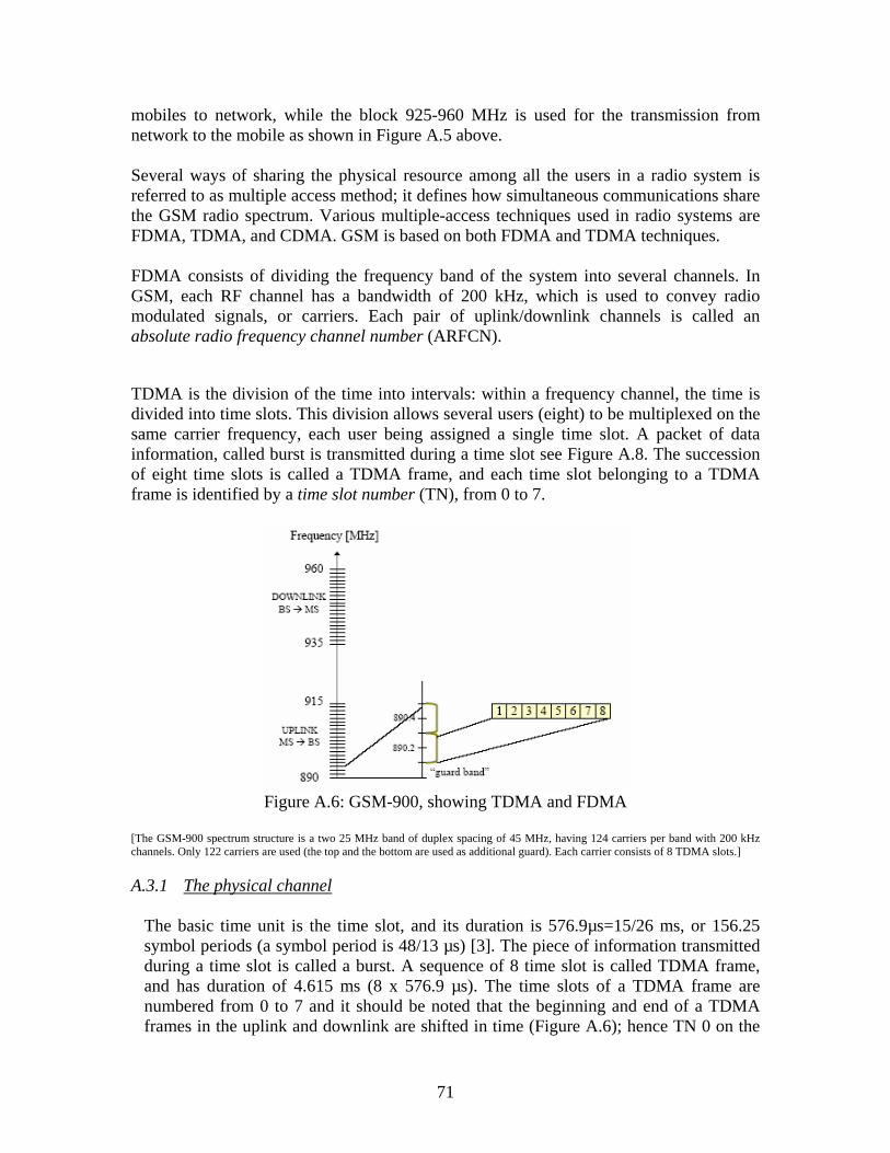
71
mobiles to network, while the block 925-960 MHz is used for the transmission from network to the mobile as shown in Figure A.5 above. Several ways of sharing the physical resource among all the users in a radio system is referred to as multiple access method; it defines how simultaneous communications share the GSM radio spectrum. Various multiple-access techniques used in radio systems are FDMA, TDMA, and CDMA. GSM is based on both FDMA and TDMA techniques. FDMA consists of dividing the frequency band of the system into several channels. In GSM, each RF channel has a bandwidth of 200 kHz, which is used to convey radio modulated signals, or carriers. Each pair of uplink/downlink channels is called an absolute radio frequency channel number (ARFCN).
TDMA is the division of the time into intervals: within a frequency channel, the time is divided into time slots. This division allows several users (eight) to be multiplexed on the same carrier frequency, each user being assigned a single time slot. A packet of data information, called burst is transmitted during a time slot see Figure A.8. The succession of eight time slots is called a TDMA frame, and each time slot belonging to a TDMA frame is identified by a time slot number (TN), from 0 to 7.
Figure A.6: GSM-900, showing TDMA and FDMA
[The GSM-900 spectrum structure is a two 25 MHz band of duplex spacing of 45 MHz, having 124 carriers per band with 200 kHz channels. Only 122 carriers are used (the top and the bottom are used as additional guard). Each carrier consists of 8 TDMA slots.] A.3.1 The physical channel
The basic time unit is the time slot, and its duration is 576.9µs=15/26 ms, or 156.25 symbol periods (a symbol period is 48/13 µs) [3]. The piece of information transmitted during a time slot is called a burst. A sequence of 8 time slot is called TDMA frame, and has duration of 4.615 ms (8 x 576.9 µs). The time slots of a TDMA frame are numbered from 0 to 7 and it should be noted that the beginning and end of a TDMA frames in the uplink and downlink are shifted in time (Figure A.6); hence TN 0 on the

72
uplink corresponds to TN3 in the downlink. This allows some time for the mobile to switch from one frequency to the other. A physical channel is defined as a sequence of TDMA frames, a timeslot number (from 0 to 7) and a frequency. It is bidirectional with the same TN in uplink and in downlink. In order to support cryptographic mechanisms, a long time-structure has been defined, this structure is called a hyperframe and has a duration of 3 hours, 28 minutes, 53 seconds, and 760 ms (or 12,533.76 seconds) [3]. The TDMA frames are numbered within the hyperframe.
The numbering is done with the TDMA frame number (FN) from 0 to 2,715,647. One hyperframe is subdivided into 2,048 superframes, which have duration of 6.12 seconds. The superframe is itself subdivided into multiframes. In GSM, there are two types of multiframes defined, containing 26 or 51 TDMA multiframes. The 26 multiframe has duration of 120 ms, and occupies 26 TDMA frames. This multiframe is used to carry Traffic Channel (TCH), SACCH, and Fast Associated Control Channel (FACCH). The 51 multiframe is made up of 51 TDMA frames. Its duration is 235.4 ms (3,060/13) and it is used to carry BCCH, Common Control Channel (CCCH), and Stand Alone Dedicated Control Channel (SDCCH) (with its associated SACCH). A superframe is composed of twenty-six 51-multiframes, or of fifty-one 26-multiframes, this hierarchical time structure is better summarised in Figure A.8.
1.73 ms
6 7 0 1 2 3 4 5 6 7 0
3 4 5 6 7 0 1 2 3 4 5 200 kHz
Frame= 4.62 ms
45 MHzMS to BS uplink
1
6 7
2
Figure A.7: Uplink and downlink TDMA frames showing 3 timeslots offset
BS to MS Downlink

73
Figure A.8: Time Frames, Time slots and Bursts
There are four different types of bursts used for transmission in GSM. The normal burst (NB) is used to carry data (on traffic channel) and most signalling (on control channel), except for RACH, SCH, and FCCH. It has a total length of 156.25 bits, made up of two 57 bit information bits, a 26 bit training sequence used for equalization, 1 stealing bit for each information block (used for FACCH), 3 tail bits at each end, and an 8.25 bit guard sequence, as shown in Figure A.8. The 156.25 bits are transmitted in 0.577 ms, giving a gross bit rate of 270.833 kbps. The frequency correction burst (FB), is used on the FCCH, and the synchronization burst, (SB) is used on the SCH, have the same length as a normal burst, but a different internal structure, which differentiates them from normal bursts (thus allowing synchronization). The access burst (AB) is shorter than the normal burst, and is used only on the RACH. A.3.2 The GSM Logical Channels The association of radio frequency channel and a time slot yields the pair, ARFCN and TN and this uniquely defines a physical channel on both the uplink and the downlink. On top of the physical channels, logical channels are mapped to convey information of voice, data, and signalling. The signalling information is used in setting up a call, or to adapt the

74
link to rapidly changing radio conditions, and so on. Logical channels can be seen as pipes, each one used for different purpose by the higher of the system. There are two types of logical channels- traffic channels and control channels. Based on their functions, four classes of control channels are defined: broadcast, dedicated, common and associated. A broadcast channel is used by the network (in the downlink only) to send general information to the MSs. A channel is said to be dedicated if only one MS can transmit or receive in the ARFCN-TN defining this channel, and common if it carries information for several mobiles. An associated control channel is allocated to one mobile, in addition to a dedicated channel, and carries signalling for the operation of this channel. The broadcast channels are transmitted on the beacon carrier frequency. The purposes of the beacon are:
• To allow a synchronization in time and frequency of the MSs to the BTS. Synchronization is needed by the MS to access the services of a cell.
• To assist the mobile in estimating the quality of the link during a communication,
by measurements on the received signal from the BTS it is transmitting to, and from the other BTSs on the geographical area. These measurements are used by the network to determine when a handover is necessary and to which BTS this handover should apply.
• To assist the mobile in the selection of a cell during idle mode (i.e. not in
communication, but still synchronized to the network and able to initiate and receive an incoming calls). This selection performed on the basis of the received power measurements made on the adjacent cell’s beacon channels.
• To access the general parameters of the cell needed for the procedures applied by
the MS, or general information concerning the cell, such as its identification, the beacon frequencies of the surrounding cells, or the option supported by the cell.
Table A.3 below shows the logical channels utilized in the GSM system and their purpose. Logical
Channels Abbreviation Uplink/
Downlink Purpose
Broadcast Channel (BCH)
Broadcast control Channel Frequency correction Channel Synchronization Channel
BCCH FCCH SCH
BSS MS BSS MS BSS MS
System Information broadcast Cell frequency synchronization Cell time synchronization and
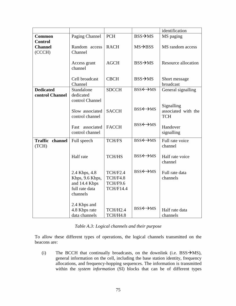
75
identification Common Control Channel (CCCH)
Paging Channel Random access Channel Access grant channel Cell broadcast Channel
PCH RACH AGCH CBCH
BSS MS MS BSS BSS MS BSS MS
MS paging MS random access Resource allocation Short message broadcast
Dedicated control Channel
Standalone dedicated control Channel Slow associated control channel Fast associated control channel
SDCCH SACCH FACCH
BSS MS BSS MS BSS MS
General signalling Signalling associated with the TCH Handover signalling
Traffic channel (TCH)
Full speech Half rate 2.4 Kbps, 4.8 Kbps, 9.6 Kbps, and 14.4 Kbps full rate data channels 2.4 Kbps and 4.8 Kbps rate data channels
TCH/FS TCH/HS TCH/F2.4 TCH/F4.8 TCH/F9.6 TCH/F14.4 TCH/H2.4 TCH/H4.8
BSS MS BSS MS BSS MS BSS MS
Full rate voice channel Half rate voice channel Full rate data channels Half rate data channels
Table A.3: Logical channels and their purpose
To allow these different types of operations, the logical channels transmitted on the beacons are:
(i) The BCCH that continually broadcasts, on the downlink (i.e. BSS MS), general information on the cell, including the base station identity, frequency allocations, and frequency-hopping sequences. The information is transmitted within the system information (SI) blocks that can be of different types

76
according to the information that is carried out. The frequency with which an SI is retransmitted on the BCCH varies with the type of information.
(ii) The FCCH, used by the MS to adjust its local oscillator (LO) to that of the
BTS oscillator, in order to have a frequency synchronization between the MS and the BTS.
(iii) The SCH used by the MS to synchronize in time with the BTS, and to identify
the cell. As shown in Table 2.3 above, the CCCH is composed of four channels; the first three are used for the MS-initiated call or for call paging (notification of an incoming call towards the MS). The RACH is used for the MS access requests to the network for the establishment of a call based on the slotted aloha method. Every time, the MS listens to PCH to determine if it is being paged, if paged it replies on the RACH to request for a signalling channel (AGCH), when MS wants to set up a mobile originating call RACH can also be used to contact the network. MS listens to the PCH to check if the network wants to make contact with it, in case of an incoming call or an incoming short message. Information on PCH is a paging message; it includes MS’s identity number (IMSI). The AGCH is used to allocate some physical resource to a mobile for signalling, following a request on the RACH. The CBCH may be used to broadcast specific news to the mobiles of a cell. The TCH can be of several types based on the services that are accessed by the subscribers-voice or data, with various possible data rates as summarized in Table 2.3. The SDCCH is one of the dedicated control channels used for registration, authentication, call setup and location updating, when call set-up is performed, the MS is told to switch to a TCH. SACCH carries signalling for the TCH or the SDCCH with which it corresponds. Information transmitted on this channel concerns the radio link control (RLC) like the power control on the corresponding TCH or SDCCH, or the time synchronization between the MS and the BTS; On the uplink, MS sends averaged measurement on its own BTS (signal strength and quality) and neighbouring BTS (signal strength) while on the downlink MS receives information concerning transmitting power to use and instructions on the timing advance. The FACCH carries the signalling that must be sent by the network to the MS to notify that handover is occurring. It works in stealing mode – it accesses the physical resources by stealing frames from the TCH.

77
A.3.3 Mapping the Logical Channels onto the Physical Channel
In mapping the TCH and the SACCH on the 26-multiframe, the TCHs, which are bidirectional channels are mapped onto the 26-multiframe. Two types of channels must be distinguished: full-rate and half-rate channels and therefore two different mappings of the TCH are possible:
Figure A.9: Mapping Logical channels onto physical channels
• A full-rate traffic channel (TCH/FS, for full speech) makes use of one time slot per TDMA frame, for each frame of the multiframes, except the frames 12 and 25. The TDMA frame 12 is used to carry the SACCH/FS, and the TDMA frame 25 is an idle frame, which means that no channel is transmitted during this entire TDMA frame.
• A half rate channel (TCH/HS) uses one time slot every two TDMA frames, due to the fact that it carries data from a half-rate voice coder.
Figure A.10: Mapping of a TCH/FS and SACCH/FS on the 26-multiframe
Two half-rate channels can be mapped on the same time slot, as seen in Figure A.11, one using TDMA frames 0, 2, 4, 6, 8, 10, 13, 15, 17, 19, 21, and 23 and the other one using
Broadcast
Common Control
Traffic & Dedicated Control
Physical Channel

78
frames 1, 3, 5, 7, 9, 11, 14, 16, 18, 20, 22, and 24. The SACCH/HS channel associated with the first TCH subchannel is transported on TDMA frame 12, and SACCH/HS associated with the second subchannel is on time slot 25.
Figure A.11: Mapping of a TCH/HS and SACCH/HS on the 26-multiframe A3.4 Radio link Control in GSM Some procedures are involved in order to improve the efficiency of the GSM system by actually adapting the transmission between the mobile and the BTS to the continuously varying radio environment. Propagation Delay Compensation There exists a propagation delay as a result of distance between the MS and BTS, which is equals to d/c seconds, where d is the MS to BTS distance in metres, and c is the speed of light (c = 3 x 10⁸ m.s-1). With no compensation of this delay, the bursts transmitted by two different MSs, in the same TDMA frame on two consecutive slots, could interfere with one another. If for instance, there is an MS (MS1) situated about 25 km away from the BTS, transmitting on time slot 0 of a given channel frequency; another MS2 is located, say, 1 km away from the BTS, and transmitting on time slot 1 of the same frequency. MS2 will experience a very short delay (about 3.33 µs), but the burst on time slot 0, from MS1 will be received by the BTS 83.33 µs after it has been transmitted. This implies that, at the BTS receiver, the burst on time slot 0 will interfere with the beginning of the burst of time slot 1, for a period of about 80 µs. In order to cope with this kind of problem, the network manages a parameter for each mobile called the TA, which represents the transmission delay between the BTS and the MS, added to the delay for the return link. The estimation of this delay is performed by the BTS upon reception of an AB on the RACH. This burst is characterized by a longer guard period (68.25-bit duration or 252 µs) to allow burst transmission from a mobile that

79
does not know the TA at the first access. The received AB allows the BTS to estimate the delay by means of a correlation with the training sequences. The value of the TA is between 0 and 63 symbols periods (i.e., between 0 and 232.615 µs by steps of 48/13 µs), is transmitted on the AGCH. It allows the MS to advance its time base, so that the burst received at the BTS arrives exactly three timeslots after the BTS transmit burst, as shown in Figure A.12. A distance of 35 km between the MS and the BTS is therefore possible- the 232.675 µs allows compensating for a distance of around 70 km, including the forward and return links.
After this first propagation delay the BTS continuously monitors the delay of the NBs sent from Ms on the other logical channels. If the delay changes by more than one symbol period, a new value of the TA is signalled to the MS on the SACCH. The MS Power Control The MS can vary its transmit output power from a maximum defined by its class (ref [3]. section 1.5.6.1), by steps of 2dB. When an MS in communication mode, the MS and BTS measure the received signal strength and quality (based on bit error ratio) and pass the information to the BSC, which ultimately decides if and when the power level should be changed. A command is then sent to the MS on the SACCH. Power control is a difficult mechanism to implement because of possible instability. This arises from having MS in cochannel cells, alternatively increasing their power in response to increased cochannel interference. If for instance, mobile A increases its power because the corresponding BTS receives a cochannel interference caused by mobile B, in another cell. Then the BTS receiving the signal from mobile B might request mobile B to increase its power, and so forth. This is the reason why some coordination is
The uplink burst is advanced by twice the BTS to MS propagation delay
BTS to MS propagation delay
BTS clock
MS clock
7 0 1 2 3 4 5 6 7 0
Uplink burst
Downlink burst
1
4 5 6 7 0 1 2 3 4 5 6 7
2
Figure A.12: Correction of MS transmission timing for propagation delay
TDMA frame N
TDMA frame N

80
required at the BSC level. For access request on the RACH, the MS uses maximum power level defined by the parameter MS_TXPWR_MAX_CCH broadcast by the network. Frequency Hopping The radio environment depends on the radio frequency, in order to avoid important differences in the quality of the channels; a feature called slow frequency hopping (FH) was introduced. The slow FH changes the frequency with every TDMA frame, which also has the effect of reducing the cochannel interference. This capability is optionally used by the operator, and is not necessarily implemented in all the cells of the network, but it must be supported by all MSs. The main advantage of the FH is to provide diversity on one transmission link (especially to increase the efficiency of coding and interleaving for slowly moving MSs) and also to average the quality on all the communications through interference diversity. The principle of slow FH is that every mobile transmits its time slots according to a sequence of frequencies that it derives from an algorithm. The FH sequences are orthogonal inside one cell (i.e., no collisions occur between communications of the same cell) and independent from one cell to a cochannel cell (i.e. a cell using the same set of RF channels or cell allocation). Hopping sequence is derived by the mobile from parameters broadcast at the channel assignment, namely, the mobile allocation (ser of N frequencies on which to hop), the hopping sequence number (HSN) of the cell (which allows different sequences on the cochannel cells), and the index offset (to distinguish the different mobiles of the cell using the same mobile allocation) or mobile allocation index offset (MAIO); based on these parameters and on the FN, the MS is aware which frequency to hop in each TDMA frame. The physical channel supporting the BCCH does not hop. A.4 The MS in Communication Mode MS Cell Synchronization Procedure Before Ms synchronizes to a cell, it first searches for the FB on the FACCH. This allows a first timing synchronization, but ultimately it allows the mobile to adjust its oscillator to be synchronized into the frequency domain with the BTS. This is possible because When an MS is assigned a TCH or SDCCH, during the time slots that are not used for these channels and for the associated SACCH, the MS performs measurements on all the adjacent BCCH frequencies. These measurements are sent to the network by means of the SACCH, and are interpreted by the NSS for the power control and handover procedures. Measurements are performed in each TDMA frame, and are referred to as monitoring, which consists of estimating the receive signal strength on a given frequency. The list of frequencies to be monitored is broadcast on the BCCH, by means of the BCCH allocation (BA) list, which contains up to 32 frequencies. The frequencies are monitored one after

81
the other, and the measured samples are averaged prior to the reporting to the network, on an uplink SACCH block, under form of a value called RXLEV. The MS then measures the received signal strength level from the surrounding cells by tuning and listening to their BCCH carriers; the measurements are reported at every reporting period. For a TCH/FS, the reporting period is 104 TDMA frames (480 ms). It is essential that the MS identify which surrounding BSS is being measured in order to ensure reliable handover. Because of frequency reuse with small cluster sizes, the BCCH carrier frequency may not be sufficient to uniquely identify surrounding cell. The cell in which the MS is situated may have more than one surrounding cell using the same BCCH frequency. It is therefore necessary for the MS to synchronize to and demodulate the BCCH carriers to identify the base station identity code (BSIC) in the SB. In order to do so, the MS uses the idle frames. These frames are termed “search” frames. A window of nine consecutive slots is needed to find the time slot 0 on the BCCH frequency (note that time slot 0 carries the SCH and the FCCH), since the beacon channel are not necessarily synchronized with one another. One other important characteristic to notice is that the SCH and FCCH are mapped onto the 51-multiframe, and that the idle frame of the mobile during communication occurs on the 26 multiframe. Since 26 and 51 are mutually prime numbers, this means a search frame will be available every 26 modulo 51 frame on the beacon channel. For instance, if an idle frame occurs in the frame 0 of the 51 multiframe, the next idle frame will be programmed on frames 26, 1, 27, 2, and so on. Then, after a certain number of search frames, the MS will necessarily decode an FB and SB. A4.1 Ms Operation in Idle Mode In GSM phase 2 recommendations, the idle mode of the MS is described. The idle can be divided into three (3) processes, which are: PLMN selection, cell selection and reselection, and location updates. In idle mode, the MS has no channel of its own but it is:
(i) Required to synchronize in time and frequency to a given cell, selected as the best suitable cell with regards to a set of criteria based on the beacon received by the MS. This is termed “camping onto” a cell. This process of evaluating different cells and choosing the best suitable one is called cell selection, or reselection, if performed again, due to degradation of the link quality with the previously selected cell. During idle mode, the MS continuously measures the radio link quality of the serving and the surrounding cells, so that cell reselection criteria are evaluated periodically.
(ii) Listens to possible incoming calls from the network. The notification of an incoming call is usually known as paging.
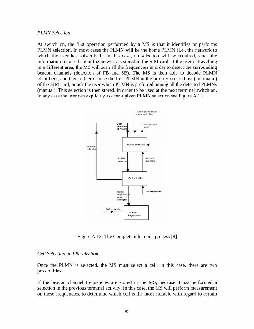
82
PLMN Selection At switch on, the first operation performed by a MS is that it identifies or performs PLMN selection. In most cases the PLMN will be the home PLMN (i.e., the network to which the user has subscribed). In this case, no selection will be required, since the information required about the network is stored in the SIM card. If the user is travelling in a different area, the MS will scan all the frequencies in order to detect the surrounding beacon channels (detection of FB and SB). The MS is then able to decode PLMN identifiers, and then, either choose the first PLMN in the priority ordered list (automatic) of the SIM card, or ask the user which PLMN is preferred among all the detected PLMNs (manual). This selection is then stored, in order to be used at the next terminal switch on. In any case the user can explicitly ask for a given PLMN selection see Figure A.13.
Figure A.13: The Complete idle mode process [8] Cell Selection and Reselection Once the PLMN is selected, the MS must select a cell, in this case, there are two possibilities. If the beacon channel frequencies are stored in the MS, because it has performed a selection in the previous terminal activity. In this case, the MS will perform measurement on these frequencies, to determine which cell is the most suitable with regard to certain

83
criteria. Once the best cell has been selected, the MS performs registration and “camps” on this cell. Note that if the stored frequency list beacon carriers are not detected by the MS, it will perform the PLMN selection again. If it is the first time the PLMN is accessed, the carriers of the system are scanned, in order to detect the beacon channels, and the received signal strength of these channels is added in an ordered list. Once this is achieved, the cell selection can be performed, as in the previous case. In order to speed up the process, a list of the RF channels containing BCCH carriers of the same PLMN is broadcast in the system information messages. When an MS camps on a cell, it can receive paging blocks on the PCH, or even initiate call setup for outgoing calls by sending an AB on the RACH. MS continuously keeps the list of six strongest BCCH carriers, from the radio propagation point of view it is desirable that the MS camp onto a cell with the lowest path loss. The most favourable cell is indicate by the C1 criteria, which is a radio parameter; these criteria compose of the followings (and they are received through BCCH): signal received by MS on beacon frequency, maximum transmitted power of the MS and some parameters specific to the cell. The parameter C1 is given by C1 = (A – Max. (B, 0)) A = Received Level Average – P1 B = P2 - Maximum RF power of MS {all values expressed in dB} [Large value on parameter A indicates a strong signal on the downlink; a large value on parameter B indicates a weak MS compared to the allowed power in the cell] Where
P1 = RXLEV_ACCESS_MIN (The minimum allowed RXLEV for an MS to access that cell)
P2 = MX_TXPWR_MAX_CCH (Max. transmission power MS is allowed to use on RACH)
In order for a cell reselection to take place, one of the following events must have occurred:
A cell’s C1 must be higher than any other C1 of any other cell found by the MS within the same Location Area (LA)
There is a downlink signalling failure (i.e., the success rate of the MS decoding signalling blocks drops too low).
These parameters are broadcasted by the cell

84
Cell’s C1 must be higher than the C1 of any other cell found by the MS in different LAs of the same PLMN
Criterion C1 for the cell must be higher than 0 The cell camped on has been barred for access A random access attempts is still unsuccessful after a given number of repetitions,
specified by a broadcast parameters In cell re-selection, another parameter included to C1 – the parameter is C2; it is used by phase 2 MS for cell re-selection. The following summarises the facts about cell re-selection:
C1 and C2 parameters are used to ensure that MS is camped on the cell with highest probability of successful communication for both uplink and downlink.
To monitor changes in the cell parameters, system information messages must be read at least once every 30 seconds.
The MS attempts to decode BCCH data blocks that contain parameters affecting cell re-selection for each of the six strongest neighbouring BCCH carriers at least every 5 minutes.
The BCCH information is used to calculate C1 and C2 The C1 and C2 values for serving and non-serving cells are regularly calculated
by the MS C2 is defined as C2 = C1 + CELL_RESELECT_OFFSET – TEMPORARY_OFFSET When timer T < PENALTY_TIME C2 = C1 - CELL_RESELECT_OFFSET The timer T is started separately for each cell in the list of the six strongest cells. When the cell is removed from the list, T is reset to 0. Monitoring of the Paging Blocks The logical channel PCH is used to covey paging blocks on the downlink. These blocks are used to notify the MS of an incoming call. In order to conserve MS’s power, a PCH is divided into subchannels, each corresponding to a group of MSs. Each MS will only “listen” to its subchannel and will stay in the sleep mode during other subchannels of the PCH. This is called the discontinuous reception (DRX) mode. The mobile knows in which group it belongs by determining the parameter CCCH_GROUP. It is estimated with an algorithm, which inputs are the mobile IMSI and the parameter BS_CC_CHANS, broadcast on the BCCH. This parameter defines the number of basic physical channels supporting CCCH.

85
Mobiles in a specific CCCH_GROUP will listen for paging messages and make random accesses only on the specific CCCH to which the CCCH_GROUP belongs. The MS is not authorized to use DRX mode of operation while performing the cell-reselection algorithm [3].

86
Appendix B: GPRS
B.1 The GPRS Architecture The GPRS system is based upon the existing GSM infrastructures; it represents an evolution of the standard, which allows data transmission in packet mode and providing higher throughputs as compared with the circuit-switched mode. This evolution is usually presented under the designation of 2.5G to point out that it is a transition technology between 2G and 3G [3]. Figure B.1 shows the evolution of standards towards 3G without full explanation; this is intentionally avoided because the emphasis is not on the evolution of standards but rather to show how GPRS fits in the migration towards 3G.
Figure B.1: Evolution of standards towards 3G showing GPRS [4] The packet switched GPRS (Releases 1998 and 1999) service can co-exist with the circuit switched GSM service and therefore, it can utilise the existing GSM physical nodes [5] (see Figure 1). GPRS however, is an enhancement over the GSM and adds some nodes in the network to provide the packet switched services. These network nodes are called GSNs (GPRS Support Nodes) and are responsible for the routing and delivery of the data packets to and from the MS and external packet data networks (PDN) - these are the Gateway GPRS Support Node (GGSN) and the Supporting GPRS Support Node (SGSN). With the introduction of GGSN and SGSN into GPRS network, the subnetwork formed by these GGSN and SGSN is called the GPRS core network. In order to reuse GSM nodes new interfaces have been defined between the GSM network nodes and the different elements of GPRS core network. The GPRS logical architecture, showing different entities and interfaces are shown in Figure B.2 below:
GSM
HSCSD
GPRS
EDGE
3G

87
Figure B.2: GPRS General Architecture showing signalling and data transfer interfaces
B1.1 The GPRS Entities Mobile Station (MS) The MS is a combination of mobile terminal (MT) and terminal equipment (TE); it is however possible that MT and TE be in the same piece of equipment (e.g. smart phone, communicator, or even some present GPRS phones), or in a separate devices like a regular GPRS-phone connected to a handheld computer or a laptop. Three MS-classes have been identified, which are Class A, class B, and class C. Class A supports simultaneous communication in circuits-switched mode and another one in packet-switched (PS) mode – supports simultaneous attach, activation and monitoring. It is capable of detecting in idle mode an incoming call in circuit or packet switched mode. Class B detects an incoming call in circuit-switched (CS) mode or in packet-switched mode during the idle mode but cannot support them simultaneously. The packet and circuit calls are performed sequentially. However signalling such as attach and activation can be simultaneous – i.e. GPRS connection shall not be cleared down (deactivated) due to the invocation of GSM –traffic. MSs that belong to class C supports either communication in circuit-switched mode or in packet-switched mode, but are not capable of simultaneous support in both modes. It is not capable of simultaneously detecting the incoming calls in circuit-switched mode and packet-switched mode during idle mode. This implies that a class C MS can either be configured as a circuit-switched mode or packet-switched mode.
E
TE MT BSS+PCU SGSN GGSN PDN TE
Other PLMN
GGSN
MSC/VLR HLR
SMS-GMSC SMS-IWMSC
SM-SC
SGSN
HLR
C Gd
Gr
D
Gc Gi
Gn
Gf Gp Gn
Gs
R
A
Um Gb
Signalling Interface
Signalling and Data Transfer Interface
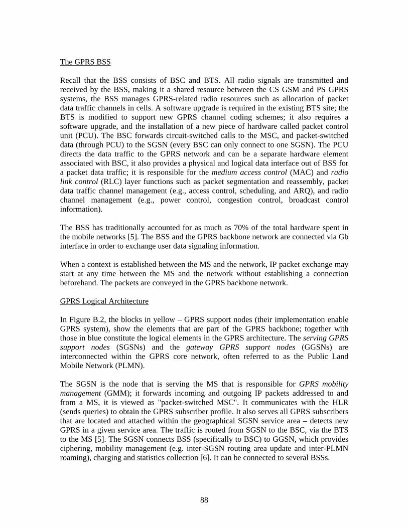
88
The GPRS BSS Recall that the BSS consists of BSC and BTS. All radio signals are transmitted and received by the BSS, making it a shared resource between the CS GSM and PS GPRS systems, the BSS manages GPRS-related radio resources such as allocation of packet data traffic channels in cells. A software upgrade is required in the existing BTS site; the BTS is modified to support new GPRS channel coding schemes; it also requires a software upgrade, and the installation of a new piece of hardware called packet control unit (PCU). The BSC forwards circuit-switched calls to the MSC, and packet-switched data (through PCU) to the SGSN (every BSC can only connect to one SGSN). The PCU directs the data traffic to the GPRS network and can be a separate hardware element associated with BSC, it also provides a physical and logical data interface out of BSS for a packet data traffic; it is responsible for the medium access control (MAC) and radio link control (RLC) layer functions such as packet segmentation and reassembly, packet data traffic channel management (e.g., access control, scheduling, and ARQ), and radio channel management (e.g., power control, congestion control, broadcast control information). The BSS has traditionally accounted for as much as 70% of the total hardware spent in the mobile networks [5]. The BSS and the GPRS backbone network are connected via Gb interface in order to exchange user data signaling information. When a context is established between the MS and the network, IP packet exchange may start at any time between the MS and the network without establishing a connection beforehand. The packets are conveyed in the GPRS backbone network. GPRS Logical Architecture In Figure B.2, the blocks in yellow – GPRS support nodes (their implementation enable GPRS system), show the elements that are part of the GPRS backbone; together with those in blue constitute the logical elements in the GPRS architecture. The serving GPRS support nodes (SGSNs) and the gateway GPRS support nodes (GGSNs) are interconnected within the GPRS core network, often referred to as the Public Land Mobile Network (PLMN). The SGSN is the node that is serving the MS that is responsible for GPRS mobility management (GMM); it forwards incoming and outgoing IP packets addressed to and from a MS, it is viewed as "packet-switched MSC". It communicates with the HLR (sends queries) to obtain the GPRS subscriber profile. It also serves all GPRS subscribers that are located and attached within the geographical SGSN service area – detects new GPRS in a given service area. The traffic is routed from SGSN to the BSC, via the BTS to the MS [5]. The SGSN connects BSS (specifically to BSC) to GGSN, which provides ciphering, mobility management (e.g. inter-SGSN routing area update and inter-PLMN roaming), charging and statistics collection [6]. It can be connected to several BSSs.

89
The GGSN provides gateway between the GPRS network and packet data networks (PDN) – IP and X.25. It is a router that forwards the incoming packets from the external PDN to the SGSN of the addressed MS [3]. It is connected with SGSNs via an IP-based GPRS backbone network [5]. It maintains routing information to tunnel the PDU to the SGSNs GGSN deals with session management, specifically the connection towards the external networks [5]. The HLR is a database that contains, among other things, packet domain subscription data and routing information. The MSC/VLR coordinates the setting up of calls to and from GSM users and manages GSM mobility. The MSC is not directly involved in the GPRS network. It forwards circuit-switched paging for the GPRS-attached MSs to the SGSN when Gs interface is present [3]. Usually, the node is denoted MSC/VLR since the MSC and the VLR usually reside in the same physical node The EIR is a database that contains terminal identities. The short message service gateway MSC (SMS-GMSC) and the short message service interworking MSC (SMS-IWMSC) are not changed for GPRS use. There is a new interface to the SGSN, however, in order to enable GPRS MSs to send and receive SMS over GPRS radio channels [5]. Since SMS over GPRS still is a store-and-forward service, the SMS-GMSC and the SMS-IWMSC are directly connected to the SMS-centre, where messages are either dropped or eventually routed to the respective destinations [5]. The authentication centre (AuC) is an extension to the HLR (often in the same physical node); and it contains all the information required to protect subscriber’s identity [6: 77-92]. Radio interface is inherently open for unauthorized access, hence authentication keys are given to users from the AuC every time they open a GSM or GPRS connection; this ultimately leads to prevention of potential fraud and eavesdropping of a conversation or data transmission. Authentication algorithms and encryption code are stored in the AuC and strict rules apply for access to this information [6]. B2 The Transmission and the Signalling Planes
The protocol layers have been split into two planes. The transmission plane, is mainly used for the transfer of user data, and associated control procedure like flow control and error handling. On the other hand, there is the signalling plane, used for the control and support of the transmission plane functions as well as routing and mobility management. B2.1 The Transmission Plane In contrast to GSM, the GPRS protocol stack for the transmission plane contains a new layer that deals with data traffic or user data transfer. Figure B.3 below illustrates the layered protocol structure between the MS and the GGSN. The protocols used on each of the interface, shall be addressed.
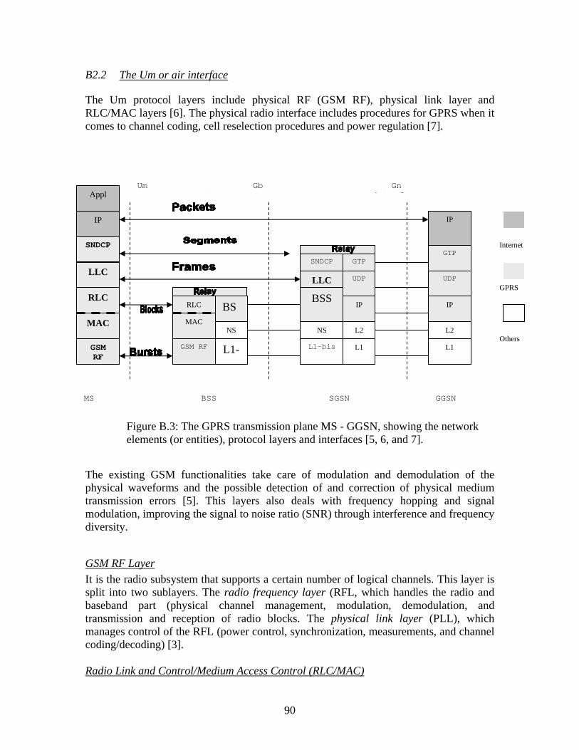
90
B2.2 The Um or air interface The Um protocol layers include physical RF (GSM RF), physical link layer and RLC/MAC layers [6]. The physical radio interface includes procedures for GPRS when it comes to channel coding, cell reselection procedures and power regulation [7].
The existing GSM functionalities take care of modulation and demodulation of the physical waveforms and the possible detection of and correction of physical medium transmission errors [5]. This layers also deals with frequency hopping and signal modulation, improving the signal to noise ratio (SNR) through interference and frequency diversity.
GSM RF Layer It is the radio subsystem that supports a certain number of logical channels. This layer is split into two sublayers. The radio frequency layer (RFL, which handles the radio and baseband part (physical channel management, modulation, demodulation, and transmission and reception of radio blocks. The physical link layer (PLL), which manages control of the RFL (power control, synchronization, measurements, and channel coding/decoding) [3]. Radio Link and Control/Medium Access Control (RLC/MAC)
Appl
IP
SNDCP
LLC
RLC
MAC
GSM RF
RLC
GSM RF
MAC
L1-
NS
BS
L1-bis L1
NS L2
BSSIP
LLC UDP
SNDCP GTP
L1
L2
IP
UDP
GTP
IP
MS BSS SGSN GGSN
Um Gb Gn i t f
Internet
GPRS
Others
Figure B.3: The GPRS transmission plane MS - GGSN, showing the network elements (or entities), protocol layers and interfaces [5, 6, and 7].

91
RLC/MAC are considered to be part of the same sublayer, the RLC/MAC layer provides services for information transfer over the GPRS physical layer; its functions include backward error correction procedures enabled by the selective retransmission of erroneous blocks . RLC deals with block segmentation and reassembling of LLC data packets, buffering and retransmission with backward error correction. RLC provides a reliable link between the MS and the BSS. MAC controls the access signalling and RLC blocks from different users onto the GSM physical. Channel access (scheduling, queuing, contention, and resolution), PDCH multiplexing, and power control are some of the functions of the MAC layer [6]. As shown in Figure B.4, the RLC data block is given a MAC header and a block check sequence (BCS) to form a radio block. In turn convolutional coding is applied to the radio block with a few additional tail bits, forming a coded radio block with a fixed length of 456 bits. The amount of information-bits in this standard transmission unit varies, depending on the coding scheme the physical radio interface is using in each case (CS-1 to CS-4 gives 181 to 428 bits respectively).
Figure B.4: The RLC block and radio block [5] RLC blocks that are erroneously received by the MS or BTS are retransmitted by a selective admission request (ARQ) protocol. On the same sub layer, the MAC function controls the access signalling (request and grant) procedures for the radio channel, as well as the mapping of segmented frames onto the GSM channel. In other words, it distributes all the data traffic and control signalling on the physical radio interface.
The Channel Coding Scheme Four different channel coding schemes (CS) are defined in the GPRS specifications. Each of these coding schemes incorporates a different level of data integrity checks (error correction overhead) to data transmitted over the radio interface. The GPRS user data is sent on radio blocks encoded with one of these four channel coding schemes; they are commonly labelled CS-1 to CS-4.
Convolutional Coding
MAC Header RLC Header Information bits BCS Tail
Coded radio block of 456 bits (181, 268, 312 or 428 information bits)
RLC Data Block
Radio Block

92
Consider a fixed channel capacity; there is an inverse relation between the amount of actual data that can be transmitted and the amount of data integrity assurance. Basically, the channel can either be used to transfer data itself or error checks on the respective data. The different error coding procedures from varying sizes of the radio blocks, which produces four progressive data rates as listed in table one below. It must be clear that these data rates are only valid for the radio-layer, and that the data rates on the application layer will be somewhat less due to packet-overhead.
Channel Coding Scheme
Data bits in Radio Block
Data Rates per Time-slot kb/s on Radio-layer
Maximum data rate per 8 time-slots kb/s
CS-1 181 9.05 72.4 CS-2 268 13.4 107.2 CS-3 312 15.6 124.8 CS-4 428 21.4 171.2
Table B.1: Parameters associated with GPRS coding schemes [5]
Figure B.5: GPRS Data Rate on RLC Layer [9] The higher the data rates, the higher the required signal-to-noise ratio (SNR). In good channel conditions with high SNR (low interference and high spectrum efficiency), any of the four schemes could be used. In this case the channel coding schemes with the least channel protection (CS-4) will yield the highest throughput. When interference is high on the other hand, the coding scheme with the highest amount of channel protection will achieve the highest throughput (CS-1), due to extensive error coding which causes fewer retransmissions.
kbps
5
10
15
20
25
CS 1 CS 2 CS 3 CS 4
9.05
13.4
15.6
21.4
Used for all control channels, except PRACH and PTCCH/U
All CSs can be used for PDTCH

93
It is the base station that calculates which channel coding scheme that should be used for each GPRS connection and it important to note that it is only for extremely good link radio conditions that CS-4 is feasible, since it incorporates no error protection. B2.3 The Gb Interface The Gb interface supports data transfer in the transmission plane. It is located between the SGSN and the BSS, and allows many users to be multiplexed over the same physical resource. Unlike GSM A interface where the resources of a circuit switched connection are dedicated to a user throughout the whole session, GPRS Gb interface only allocates resources to a user during the periods when data are actually delivered [6]. As shown in Figure B.3, the Gb interface protocols from the highest to the lowest include subnetwork-dependent convergence protocol (SNDCP), logical link control (LLC), BSS GPRS protocol (BSSGP) and network service (NS). BSSGP The NS (Network Service) transports BSS (base station system) GPRS protocol PDUs between a BSS and an SGSN (serving GPRS support node). The primary functions of the BSSGP include:
Provision by an SGSN to a BSS of radio related information used by the RLC/MAC function (in the downlink).
Provision by a BSS to an SGSN of radio related information derived from the RLC/MAC function (In the uplink).
Provision of functionality to enable two physically distinct nodes, an SGSN and a BSS, to operate node management control functions.
It conveys routing and QoS related information for the BSS (i.e. between BSS and SGSN) [3]; i.e. it transmits data packets and routing information.
It also enables the SGSN and BSS to operate node management control functions [6].
NS
It transports BSSGP PDUs and is based on a frame relay connection between the BSS and SGSN
The Gb link Layer 2 establishes Frame relay virtual circuits between virtual circuits between SGSN and BSS
On these virtual circuits, the NS transport BSSGP PDUs between BSS and an SGSN [6]
A relay function is implemented in the SGSN to relay the packet data protocol (PDP) PDUs between the Gb and Gn interfaces.
The interfaces between MS and SGSN (see Figure B.3) are:

94
SNDCP
The SNDCP above LLC performs multiplexing of data coming from different sources to be sent across LLC [4]
It maps the IP protocol to the underlying network. It provides other functions such as compression and segmentation of network
layer messages [3].
LLC
It provides a highly reliable logical link that is independent of the underlying radio interface protocols to allow introduction of alternative radio solutions with minimum changes to the GPRS internal network (e.g. EDGE)[5,6]
Provides also, a highly reliable ciphered logical link [5]. It establishes a logical link between a MS and SGSN.
B2.4 The Gn/Gp Interface The Gn interface is located between two GSNs (SGSN or GGSN) within the same PLMN, while the Gp interface is between two GSNs in different PLMNs. The Gn/Gp interface is used for the transfer of packets between the SGSN and the GGSN in the transmission plane. Gn/Gp interface support the following protocols:
GPRS tunnelling protocol (GTP), tunnels user data between the SGSN and GGSN in the GPRS backbone network
GTP operates on top of user data protocol (UDP) over IP. The layers L1 and L2 of the Gn interfaces are not specified in the GSM/GPRS standard [3]
UDP carries the GTP PDUs in the GPRS core network for protocols that do not
need a reliable data link (e.g., IP)
Internet Protocol (IP) is used for routing user data and control signalling within the GPRS backbone network.
B2.5 The Signalling Plane The signalling plane consists of protocols for control and support of the transmission plane functions. It controls both the access connections to the GPRS network (e.g., GPRS-attach and GPRS detach) and the attributes of an established network access connection (e.g., activation of PDP address). It manages the routing of information for a dedicated network connection in order to support user mobility and controls the assignment of network resources. B2.5.1 Protocols Between MS and SGSN

95
The protocols in the signalling plane between the MS and the SGSN are the GPRS mobility management (GMM) and session management (SM). GMM/SM The GMM protocol supports mobility management functionalities such as GPRS attach, GPRS detach, security, RA update, and location update. The SM protocol supports functionalities such ad PDP context activation, PDP context modification, and PDP context deactivation. B2.5.2 Protocols Between Two GSNs In the signalling plane the Gn/Gp interfaces are used for the transfer of signalling between the GSNs in the GPRS backbone; Figure B.7 below shows the signalling plane between two GSNs, which is made up of the following protocols: The GTP for the control plane (GTP-C), tunnels the signalling messages between SGSNs and GGSNs, and between SGSNs in the GPRS core network. The UDP transfers signalling messages between GSNs. [21] provide detail information concerning information stored in GGSN and SGSN.
RLC
GSM RF
MAC
L1-
NS
BSS
MS BSS SGSN
Um Gb
GSM RF
RLC
LLC
GMM/ SM
MAC
L1 - bis
BSSGP
LLC
GMM/ SM
NS
Figure B.6: The GPRS signalling plane – MS – SGSN [3]
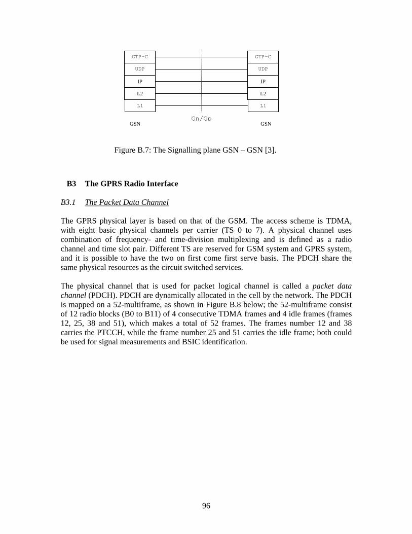
96
B3 The GPRS Radio Interface
B3.1 The Packet Data Channel The GPRS physical layer is based on that of the GSM. The access scheme is TDMA, with eight basic physical channels per carrier (TS 0 to 7). A physical channel uses combination of frequency- and time-division multiplexing and is defined as a radio channel and time slot pair. Different TS are reserved for GSM system and GPRS system, and it is possible to have the two on first come first serve basis. The PDCH share the same physical resources as the circuit switched services. The physical channel that is used for packet logical channel is called a packet data channel (PDCH). PDCH are dynamically allocated in the cell by the network. The PDCH is mapped on a 52-multiframe, as shown in Figure B.8 below; the 52-multiframe consist of 12 radio blocks (B0 to B11) of 4 consecutive TDMA frames and 4 idle frames (frames 12, 25, 38 and 51), which makes a total of 52 frames. The frames number 12 and 38 carries the PTCCH, while the frame number 25 and 51 carries the idle frame; both could be used for signal measurements and BSIC identification.
L1
IP
UDP
GTP-C
L2
L1
IP
UDP
GTP-C
L2
GSN GSN Gn/Gp
Figure B.7: The Signalling plane GSN – GSN [3].

97
0 2 7 72 7 72 20 0 0
52-multiframe (240 ms)
FigureB.8: The PDCH Structure for the GPRS B3.2 Packet Data Logical Channel GPRS, like GSM uses concept of logical channel mapped on top of the physical channels (i.e. they are carried within the physical channel). A logical channel refers to the flow of information between entities for a particular purpose. Two types of logical channels have been introduced, namely traffic channels and control channels. Three subtypes of control channels have been defined for GPRS: broadcast, common control, and associated. In addition, the GSM common control channels (BCCH, CCCH, and RACH) may be used to access the network and establish packet transfer. The different packet data logical channels and their respective tasks are summarized in Table B.2 below: Table B.2: GPRS Logical Channels
Group Logical Channels Functions Direction Packet Data Traffic Channel
PDTCH (Packet Data Traffic Channel)
Data Traffic MS BSS
Packet Broadcast Control Channel (PBCCH)
PBCCH (Packet Broadcast Control Channel)
Broadcast Control
MS BSS
Packet Common Control Channel (PCCCH)
PRACH (Packet Random Access Channel) PAGCH (Packet Access Grant Channel) PPCH (Packet Paging
Random Access Access Grant Paging
MS BSS MS BSS MS BSS
1 TDMA frame=8 TS
B0 B2 B1 B3 B4 B5 B6 B7 B8 B9 B10 B11
0 51
Bn: Radio Block n I: Idle Frames
I I
I
I

98
Channel) PNCH (Paging Notification Channel)
Multicast or Notification for PTM-M on PCCCH
MS BSS
Packet Dedicated Control Channel (PDCCH)
PACCH (Packet Associated Control Channel) PTCCH (Packet Timing Advance Control Channel)
Associated Control / resource assignment Timing Advance Control
MS BSS MS BSS
The Packet Data Traffic Channel (PDTCH) PDTCH is used to transfer user data during uplink or downlink packet transfer. The PDTCH is a unidirectional channel, either uplink (PDTCH/U) for a mobile-originated packet transfer or downlink (PDTCH/D) for a mobile-terminated packet transfer. A PDTCH is a resource allocated on one physical channel by the network for user data transmission. Packet Broadcast Control Channel (PBCCH) The presence of PBCCH in a cell is optional. PBCCH broadcasts information relative to the cell in which the MS camps and information on the neighbour cells. This information is used by the MS in order to access the network. When there is no PBCCH in the cell, the information needed by the MS to access the network for a packet transfer is broadcast on PBCCH. Packet Common Control Channel (PCCCH) The PCCCH is present in a cell only if the PBCCH is present in the cell. When it is not present, the common control signalling for GPRS is handled on the GSM CCCH. PCCCH is composed of packet random access channel (PRACH), used for random access, packet paging channel (PPCH), used for paging, and packet access grant channel (PAGCH), used for access grant. The PRACH is used by the MS to initiate uplink access to the network. The PPCH is used by the network to page the MS in order to establish a downlink packet transfer. The PAGCH is used by the network to assign radio resources to the MS for a packet transfer. Packet Dedicated Control Channel (PDCCH) The PDCCH is composed of the packet associated control channel (PACCH) and the packet timing advance control channel (PTCCH). The PACCH is unidirectional channel that is used to carry signalling during uplink or downlink packet transfer. The uplink PACCH carries signalling from the MS to the network and the downlink PACCH carries
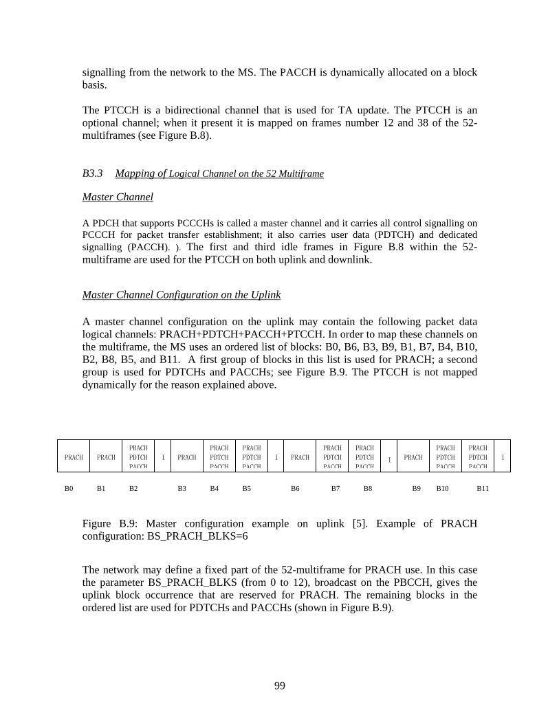
99
signalling from the network to the MS. The PACCH is dynamically allocated on a block basis. The PTCCH is a bidirectional channel that is used for TA update. The PTCCH is an optional channel; when it present it is mapped on frames number 12 and 38 of the 52-multiframes (see Figure B.8). B3.3 Mapping of Logical Channel on the 52 Multiframe
Master Channel A PDCH that supports PCCCHs is called a master channel and it carries all control signalling on PCCCH for packet transfer establishment; it also carries user data (PDTCH) and dedicated signalling (PACCH). ). The first and third idle frames in Figure B.8 within the 52-multiframe are used for the PTCCH on both uplink and downlink.
Master Channel Configuration on the Uplink A master channel configuration on the uplink may contain the following packet data logical channels: PRACH+PDTCH+PACCH+PTCCH. In order to map these channels on the multiframe, the MS uses an ordered list of blocks: B0, B6, B3, B9, B1, B7, B4, B10, B2, B8, B5, and B11. A first group of blocks in this list is used for PRACH; a second group is used for PDTCHs and PACCHs; see Figure B.9. The PTCCH is not mapped dynamically for the reason explained above. Figure B.9: Master configuration example on uplink [5]. Example of PRACH configuration: BS_PRACH_BLKS=6 The network may define a fixed part of the 52-multiframe for PRACH use. In this case the parameter BS_PRACH_BLKS (from 0 to 12), broadcast on the PBCCH, gives the uplink block occurrence that are reserved for PRACH. The remaining blocks in the ordered list are used for PDTCHs and PACCHs (shown in Figure B.9).
PRACH
PRACH
PRACH
PDTCH
PACCH
I
PRACH
PRACH
PDTCH
PACCH
PRACH
PDTCH
PACCH
I
PRACH
PRACH
PDTCH
PACCH
PRACH
PDTCH
PACCHI
PRACH
PRACH
PDTCH
PACCH
PRACH
PDTCH
PACCH
I
B0 B1 B2 B3 B4 B5 B6 B7 B8 B9 B10 B11

100
Master Channel Downlink Configuration A master configuration for the downlink may contain one of the following packet data logical channel combinations:
PBCCH+PCCCH+PDTCH+PACCH+PTCCH; PCCCH+PDTCH+PACCH+PTCCH (PCCCH=PAGCH+PPCH)
The mapping of logical channels on the radio blocks is based on the ordered list B0, B6, B3, B9, B1, B7, B4, B10, B2, B8, B5, and B11. The first block B0 is reserved for PBCCH. If more blocks are allocated for PBCCH (up to four radio blocks per 52-multiframe), then the PBCCH follows the ordered list of blocks (B6, B3, and B9). The next radio blocks in the ordered list are reserved for PAGCH, and the remaining blocks are sued for PPCH, PAGCH, PDTCH, and PACCH. The BCCH gives information on the PDCH that carries PBCCH; the following parameters are then broadcast on the PBCCH to indicate the mapping of master channel:
BS_PBCCH_BLKS is the number of blocks (1 to 4) reserved for the PBCCH within the 52-multiframe
BS_PAG_BLKS_RES is the number of blocks (0 to 12) reserved for PCCCH within the 52-multiframe where PPCH and PBCCH are excluded; if a reserved occurrence is not used by a PAGCH block, then it may be used by a PDTCH or PACCH block.
(a) Master channel supporting both PCCCH and PBCCH, with BS_PBCCH_RES=4 and BS_PAG_BLKS_RES=5
(b) Master channel supporting PCCCH but not PBCCH, with BS_PBCCH_RES=4 and BS_PAG_BLKS_RES=5
Figure B.10: Master channel configuration example on downlink [3]
PBCCH
PAGCH
PDTCH
PACCH
PAGCH
PDTCH
PACCH
I
PBCCH
PAGCH
PDTCH
PACCH
PPCH I
PBCCH
PAGCH
PDTCH
PACCH
PPCH I
PBCCH
PAGCH
PDTCH
PACCH
PPCH I
B0 B1 B2 B3 B4 B5 B6 B7 B8 B9 B10 B11
PDTCH
PACCH
PAGCH
PDTCH
PACCH
PAGCH
PDTCH
PACCH
I
PDTCH
PACCH
PAGCH
PDTCH
PACCH
PPCH
I
PDTCH
PACCH
PAGCH
PDTCH
PACCH
PPCH I
PDTCH
PACCH
PAGCH
PDTCH
PACCH
PPCH
I
B0 B1 B2 B3 B4 B5 B6 B7 B8 B9 B10 B11

101
Slave Channel Configuration for the Uplink Other PDCH that do not support PCCCHs are called slave PDCH; they carry only user data and dedicated signalling. A slave configuration for the uplink can contain the following packet data logical channels: PDTCH+PACCH+PTCCH. A PDTCH (data) or PACCH (signalling) block may occur on any uplink radio block. Slave Channel Configuration for the Downlink A downlink slave configuration is the same as for the uplink. B3.3.1 RR Management Principles B3.3.1.1 RR Operating Modes At the RR level, the MS behaviour is dependent on two operating RR states. These states are packet idle mode and packet transfer mode allows the RR activities of the MS to be characterized. Packet Idle Mode In the idle mode, no radio resources are allocated. Leaving packet idle mode occurs when upper layer request the transfer of uplink data requiring the assignment of uplink resources from the network. It also occurs at the time of reception of a downlink resource assignment command from the network for a downlink transfer. In downlink transfer, the MS switches from packet idle mode to packet transfer mode when it receives the downlink assignment command from the network. In the case of uplink transfer, the MS leaves packet idle mode when it requests the assignment of uplink resources to the network; switching to packet transfer mode is not instantaneous- the MS switches to packet transfer mode only when it has been uniquely identified at the network side, hence there is a period between packet idle mode and packet transfer mode during which the MS is in a transitory state. In packet idle mode, the MS listens to its PCH and the CBCH, this last one is the PBCCH when present in a cell or else it is the BCCH. Packet Transfer Mode When MS is in the packet transfer mode, it is clearly identified at the network side and uplink or/and downlink radio resources are allocated. Switching from packet transfer mode to packet idle mode occurs when the network releases all downlink and uplink resources. This transition can also occur in the case of an abnormal condition during packet transfer mode (e.g. radio link failure) or when the MS decides on a cell reselection toward a new cell.
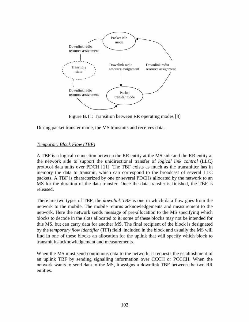
102
Figure B.11: Transition between RR operating modes [3] During packet transfer mode, the MS transmits and receives data. Temporary Block Flow (TBF) A TBF is a logical connection between the RR entity at the MS side and the RR entity at the network side to support the unidirectional transfer of logical link control (LLC) protocol data units over PDCH [11]. The TBF exists as much as the transmitter has in memory the data to transmit, which can correspond to the broadcast of several LLC packets. A TBF is characterized by one or several PDCHs allocated by the network to an MS for the duration of the data transfer. Once the data transfer is finished, the TBF is released. There are two types of TBF, the downlink TBF is one in which data flow goes from the network to the mobile. The mobile returns acknowledgements and measurement to the network. Here the network sends message of pre-allocation to the MS specifying which blocks to decode in the slots allocated to it; some of these blocks may not be intended for this MS, but can carry data for another MS. The final recipient of the block is designated by the temporary flow identifier (TFI) field included in the block and usually the MS will find in one of these blocks an allocation for the uplink that will specify which block to transmit its acknowledgement and measurements. When the MS must send continuous data to the network, it requests the establishment of an uplink TBF by sending signalling information over CCCH or PCCCH. When the network wants to send data to the MS, it assigns a downlink TBF between the two RR entities.
Packet idle mode
Transitory state
Packet transfer mode
Downlink radio resource assignment
Downlink radio resource assignment
Downlink radio resource assignment
Downlink radio resource assignment

103
In the uplink TBF, principal data flow goes from the MS to the network and it is the network that manages the allocation of the resources on the uplink (it manages the scheduling between mobiles). The mobile thus listens to “orders” from the network on the downlink to know which of the slots it can transmit on. These “orders” are identified by the TFI; it must also listen on the downlink for the acknowledgement of the packets it transmits. There are two possible allocations on the uplink – dynamic allocation and static allocation. In dynamic allocation, MS receives an identifier called uplink state flag (USF) by slot which it manages and then listens on the downlink. When it locates its identifier in the downlink block, it knows it can transmit starting from the following block. In static allocation, MS receives a message indicating the blocks in which it will be able to transmit for certain period. This allocation is limited to 128 blocks but can be repeated for another period; the mobile only knows if the allocation is renewed during acknowledgement. Thus TBF implies transmission in two directions, which could be uplink or downlink. It is possible for a mobile to have two TFIs, a TFI uplink and a TFI downlink, which shows that these two aspects are independent, hence there, could be four states: TBF not in progress, UPLINK TBF is in progress, DOWNLINK TBF is in progress and UPLINK TBF and DOWNLINK TBF are in progress.
B4 GPRS Traffic Cases B4.1 GPRS Attach GPRS attach is a procedure performed between the MS and the SGSN. In order to access the GPRS services, an MS performs an IMSI attach for GPRS services to signal its presence to the network in this case the MS informs the SGSN that it enters the GPRS network; this will not be performed automatically when the MS is switched on, the subscriber will have to request the MS to perform the procedure. . During the attach procedure, the MS provides its identity, either a temporary identifier or packet temporary mobile station identity (P-TMSI) previously allocated by the SGSN, or an IMSI identifier when P-TMSI is not valid. When MS is GPRS-attached, an MM context is established between the MS and the SGSN. This means that information related to this MS (i.e., IMSI, P-TMSI, cell identity, and RA) is stored in the SGSN. A GPRS-attached MS is localized by the network at least RA level am may be paged at any moment in the GMM STANDBY state. The GPRS attach procedure is presented in Figure B.12 below:

104
Figure B.12: GPRS Attach The RA is a group of cells in which GPRS paging is performed, it is smaller or equal to the GSM Location Area; if an MS has changed an SGSN service Area since the last update procedure the HLR will be informed by the SGSN and the information concerning the subscriber can be fetched from the old SGSN. An GPRS-Attached MS is not yet ready for data transfer ,in order for any data transfer to take place the MS must be logged on to some computer network and this requires the MS to perform PDP Context Activation procedure B4.2 PDP (Packet Data Protocol)-Context Activation A PDP context specifies access to an external packet-switching network; within GPRS, the PDP context activation is a procedure performed between the MS and the SGSN. In the first definition of GPRS this is only MS-initiated. A PDP context is handled by the MS, SGSN, and GGSN and is identified by a MS’s PDP address within these entities. Several PDP contexts can be activated at the same time within a given MS. The MS is always GPRS-attached before PDP context negotiation. The MS must provide the GPRS network with the Access Point Name (APN) describing the external network that should be contacted. The APN is a domain name. As a result of PDP context activation:
The subscriber’s user name and password will be verified by the accessed computer network
A dynamic IP-address will be allocated to the MS by the accessed computer network, the reference of GGSN, and the requested QoS.
A virtual connection (tunnel) is identified by a Tunnel Identity (TID) will be established between the SGSN and GGSN.
2
3
BSCHLR
SGSN
SGSN
EIR AUC
1, 2, 3, 4,5
‘old’
1. Attach Request (MS-SGSN)
2. Authentication (SGSN-MS)

105
(a) (b)
Figure B.13: (a) Functional PDP state model and (b) PDP context activation procedure [10]
B4.3 Cell Reselection Cell selection can be controlled either autonomously by the MS or by the network; it is based on the measurements performed by the MS. The network can order that these measurements be reported periodically. Three cell reselection modes have been defined [6: 77-92] as shown below: The GPRS cell reselection mode for a GPRS-attached MS is given by the network control mode (NETWORK_CONTROL_ORDER parameter), which is broadcast on the BCCH or PBCCH. The mobile behaviour is determined by both its GMM state and the network control mode. Whatever the value of the network control mode, when the MS is in GMM STANDBY state, it performs autonomous cell reselection and does not send measurement to the network. In GMM READY state, the MS performs cell reselection according to the network control mode.
Two criteria are defined for autonomous cell reselection:
(i) One is based on the (C1, C2) criteria, which corresponds to the GSM cell-reselection criteria.
(ii) The other one is based on the (C’1, C31, C32) criteria, which has been introduced for GPRS
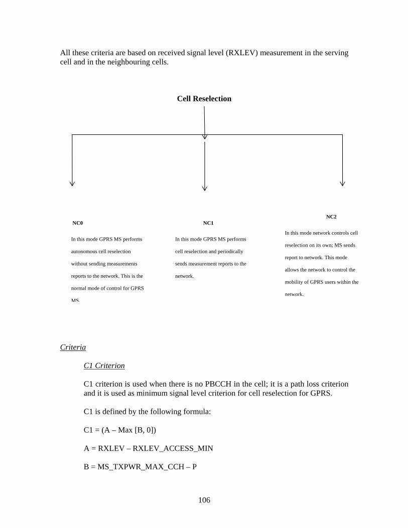
106
All these criteria are based on received signal level (RXLEV) measurement in the serving cell and in the neighbouring cells.
Criteria
C1 Criterion C1 criterion is used when there is no PBCCH in the cell; it is a path loss criterion and it is used as minimum signal level criterion for cell reselection for GPRS. C1 is defined by the following formula: C1 = (A – Max [B, 0]) A = RXLEV – RXLEV_ACCESS_MIN B = MS_TXPWR_MAX_CCH – P
NC2
In this mode network controls cell
reselection on its own; MS sends
report to network. This mode
allows the network to control the
mobility of GPRS users within the
network.
NC0
In this mode GPRS MS performs
autonomous cell reselection
without sending measurements
reports to the network. This is the
normal mode of control for GPRS
MS.
NC1
In this mode GPRS MS performs
cell reselection and periodically
sends measurement reports to the
network.
Cell Reselection

107
Where RXLEV – RXLEV_ACCESS_MIN = Minimum RXLEV at the MS to access the cell MS_TXPWR_MAX_CCH = Maximum transmit power level allowed to the MS when accessing the cell P = Maximum RF output power of the MS (Specific to the MS)
What is A? A is a reception margin; MS is allowed to enter the cell if its RXLEV is higher than RXLEV_ACCESS_MIN, this implies that A>0, if A>0 the mobile is in cell coverage and the downlink is good enough, if A<0, the MS is outside the cell coverage
What is B? B is MS transmission capability margin; if B<0, the transmission capabilities of the MS are sufficient. If MS is in cell coverage where A>0, the cell can be selected. If B>0 and A – B>0, the MS transmission capabilities are compensated by the reception margin and the cell is selected; with B>0 and A – B<0, the MS transmission are not compensated, and the MS cannot select the cell, hence the path selection criteria that is satisfied is C1>0
C’1 Criterion C’1 is the same as the C1 criterion, except that the GPRS specific parameters are used
instead C’1 = (A – Max [B, 0])
A = RXLEV – GPRS_RXLEV_ACCESS_MIN B = GPRS_MS_TXPWR_MAX_CCH – P
C2 Criterion The C2 criterion is used for cell ranking in the GSM cell-reselection process. It is computed as follows: If T < PENALTY_TIME C2 = C1 + CELL_RESELECT_OFFSET – TEMPORARY_OFFSET
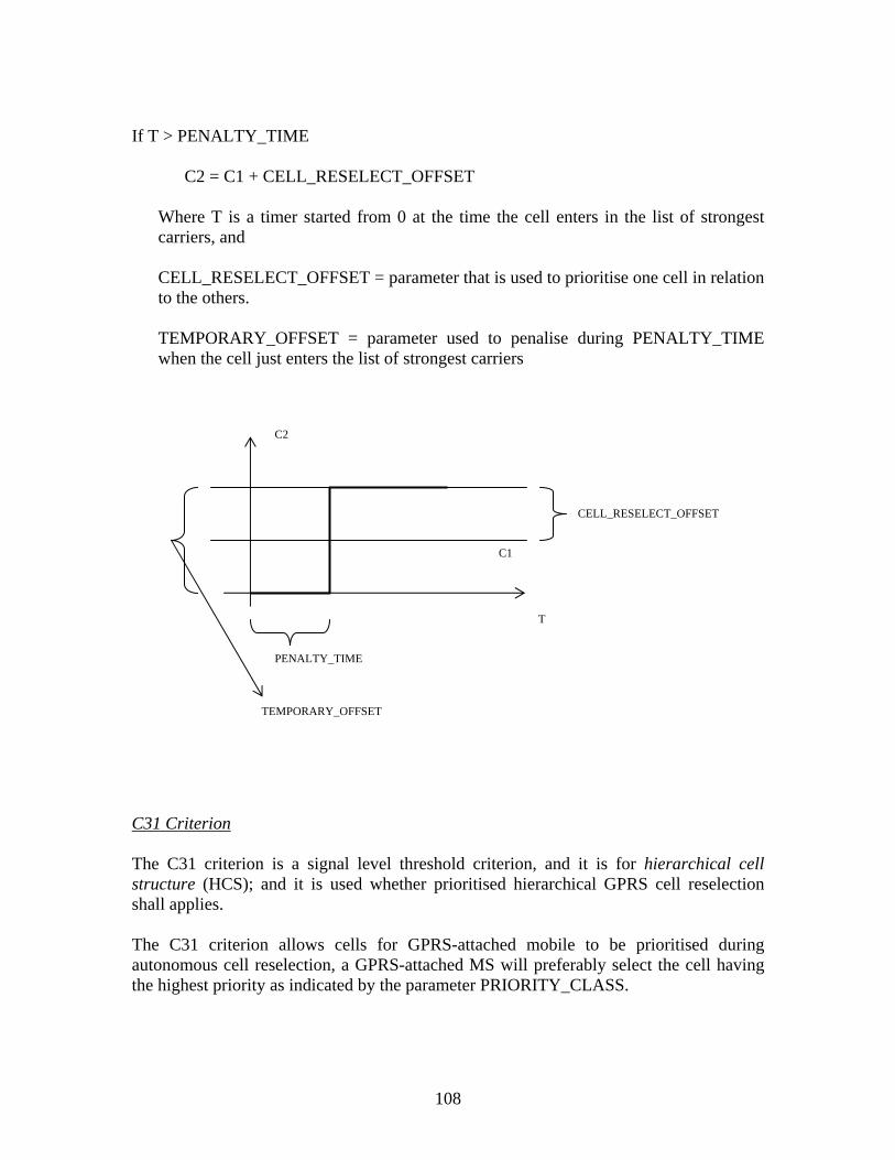
108
If T > PENALTY_TIME C2 = C1 + CELL_RESELECT_OFFSET
Where T is a timer started from 0 at the time the cell enters in the list of strongest carriers, and CELL_RESELECT_OFFSET = parameter that is used to prioritise one cell in relation to the others. TEMPORARY_OFFSET = parameter used to penalise during PENALTY_TIME when the cell just enters the list of strongest carriers
C31 Criterion The C31 criterion is a signal level threshold criterion, and it is for hierarchical cell structure (HCS); and it is used whether prioritised hierarchical GPRS cell reselection shall applies. The C31 criterion allows cells for GPRS-attached mobile to be prioritised during autonomous cell reselection, a GPRS-attached MS will preferably select the cell having the highest priority as indicated by the parameter PRIORITY_CLASS.
CELL_RESELECT_OFFSET
C2
C1
PENALTY_TIME
TEMPORARY_OFFSET
T
109
A sufficient RXLEV in the cell (HCS_THR parameter) is required for it to belong within the highest-priority class (if the signal level becomes too low, a determination of lowest priority is made). The C31 criterion contains a time-based offset, which can be used to penalise a cell belonging to another priority level as the serving cell during GPRS_PENALTY_TIME.
C31 criteria for the serving (s) and neighbour (n) cells are defined by the following formula:
C31 (s) = RXLEV(s) – HCS_THR(s) If PRIORITY_CLASS (n) = PRIORITY_CLASS(s) Then C31 (n) = RXLEV (n) – HCS_THR (n) If PRIORITY_CLASS (n) ≠PRIORITY_CLASS(s) If T < GPRS_PENALTY_TIME C31 (n) = RXLEV (n) – HCS_THR (n) – GPRS_TEMPORARY_OFFSET If T ≥ GPRS_PENALTY_TIME C31 (n) RXLEV (n) – HCS_THR (n) Where,
HCS_THR = signal threshold for applying HCS GPRS reselection (HCS_THR is
signalled on the PACCH by the serving cell)
GPRS_PENALTY_TIME = the duration for which the temporary offset GPRS_TEMPORARY_OFFSET is applied
T = a timer that is started from 0 at the time the cell enters in the list of strongest carriers. C32 Criterion The cell-ranking criterion parameter (C32) is used to select cells among those with the sale priority and is defined for the serving cell and the neighbour cells by: C32 (s) = C’1 (s) If PRIORITY_CLASS (n) = PRIORITY_CLASS(s) If T < GPRS_PENALTY_TIME

110
C32 (n) = C1 (n) + GPRS_RESELECT_OFFSET (n) – GPRS_TEMPORARY_OFFSET If T ≥ GPRS_PENALTY_TIME C32 (n) = C1 (n) + GPRS_RESELECT_OFFSET (n) If PRIORITY_CLASS (n) ≠ PRIORITY_CLASS(s)
C32 (n) = C1 (n) + GPRS_RESELECT_OFFSET (n) All the GPRS cell-reselection parameters described in this section are broadcast on the PBCCH carrier of the serving cell The cell-reselection parameters used for calculation of the (C1, C2) criteria are broadcast on the BCCH carriers of the serving cell and the BCCH carriers of the neighbouring cells. B5 Mobility
B5.1 RA A PLMN network supporting GPRS is divided into RAs, and each RA is defined by the operator of the PLMN network and may contain one several cells. A LA is a group of one or several RAs. The RA defines a paging area for GPRS, while the LA defines the paging area for incoming circuit-switched calls [3]. When a network receives an incoming call for a MS not localized at cell level but localized at RA level, it broadcasts a paging on every cell belonging to this RA. Figure B.14 illustrate RA concept. If a MS moves to a new LA, it also moves to anew RA. Each RA is identified by a routing area identifier (RAI), which is made up of a location area identifier (LAI) and a routing area code (RAC). The LAI identifies the LA, with the mobile country code (MCC) indicating the PLMN country, the mobile network code (MNC) identifying PLMN network in this country, and the location area code (LAC) identifying the LA, see Figure B.14. The RAI of each RA is broadcast on all cells belonging to this RA. In this manner, the MS is able to detect a new RA by comparing the RAI it had previously saved with the one broadcast in the new cell, and then to signal to the network its RA change. When an MS attached for circuit and packet services detects a new LA on the serving cell after having changed the cell, it will signal to the network its LA and RA change.

111
Figure B.14: RA concept
Figure B.15: Structure of RAI B5.2 GMM States There are three global states defined for GPRS mobility at the GMM layer level; these are GMM IDLE, STANDBY, and READY that allow for the characterization of the GMM activity of a GPRS MS; Figure B.16 shows the transitions between the three GMM states. They are managed in the MS and in the SGSN for each MS, and the transitions between states are slightly different on the MS and SGSN sides. A GPRS MS is in GMM IDLE state when it is not attached for GPRS service. In this state there is no GPRS mobility context established between the MS and the SGSN; this means that no information related to the MS is stored at SGSN level. In GMM STANDBY and READY states, a GPRS mobility context is established between the MS and the SGSN. A GPRS MS is in GMM STANDBY state when it is attached for GPRS services and its location is known by the network at the cell level.
MCC LAC RAC
LAI
RAI
MNC
BSS
Cell 1 BSS
Cell 3
BSS
Cell 2 BSS
Cell 4
RA 1
BSS
Cell 1 BSS
Cell 3
BSS
Cell 2 BSS
Cell 4
RA 2
Location Area
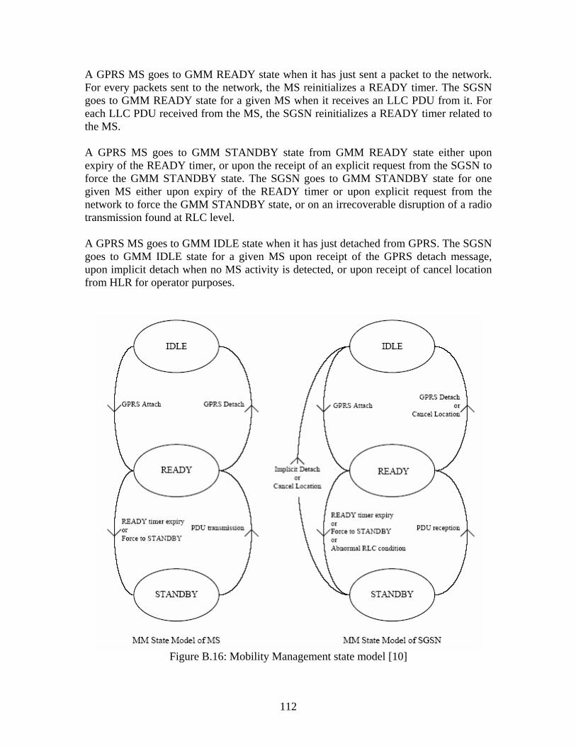
112
A GPRS MS goes to GMM READY state when it has just sent a packet to the network. For every packets sent to the network, the MS reinitializes a READY timer. The SGSN goes to GMM READY state for a given MS when it receives an LLC PDU from it. For each LLC PDU received from the MS, the SGSN reinitializes a READY timer related to the MS. A GPRS MS goes to GMM STANDBY state from GMM READY state either upon expiry of the READY timer, or upon the receipt of an explicit request from the SGSN to force the GMM STANDBY state. The SGSN goes to GMM STANDBY state for one given MS either upon expiry of the READY timer or upon explicit request from the network to force the GMM STANDBY state, or on an irrecoverable disruption of a radio transmission found at RLC level. A GPRS MS goes to GMM IDLE state when it has just detached from GPRS. The SGSN goes to GMM IDLE state for a given MS upon receipt of the GPRS detach message, upon implicit detach when no MS activity is detected, or upon receipt of cancel location from HLR for operator purposes.
Figure B.16: Mobility Management state model [10]
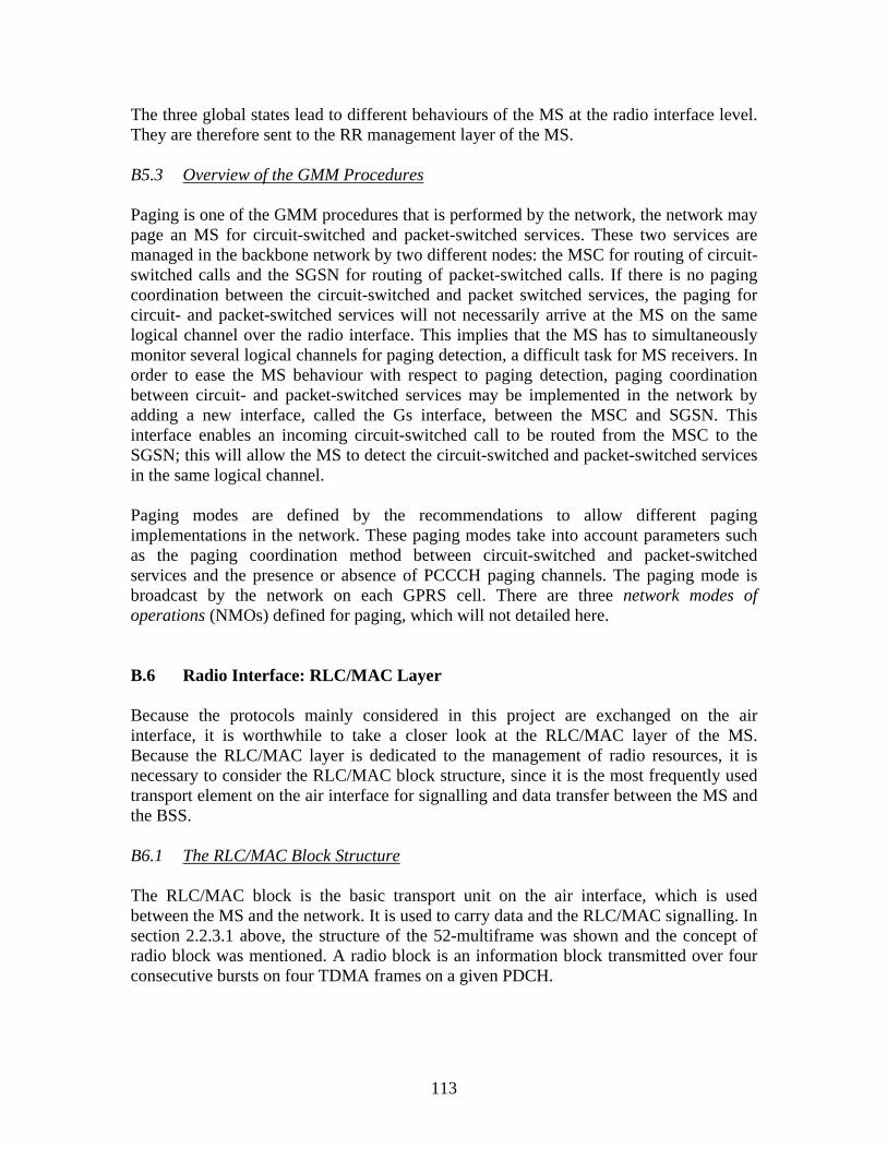
113
The three global states lead to different behaviours of the MS at the radio interface level. They are therefore sent to the RR management layer of the MS. B5.3 Overview of the GMM Procedures Paging is one of the GMM procedures that is performed by the network, the network may page an MS for circuit-switched and packet-switched services. These two services are managed in the backbone network by two different nodes: the MSC for routing of circuit-switched calls and the SGSN for routing of packet-switched calls. If there is no paging coordination between the circuit-switched and packet switched services, the paging for circuit- and packet-switched services will not necessarily arrive at the MS on the same logical channel over the radio interface. This implies that the MS has to simultaneously monitor several logical channels for paging detection, a difficult task for MS receivers. In order to ease the MS behaviour with respect to paging detection, paging coordination between circuit- and packet-switched services may be implemented in the network by adding a new interface, called the Gs interface, between the MSC and SGSN. This interface enables an incoming circuit-switched call to be routed from the MSC to the SGSN; this will allow the MS to detect the circuit-switched and packet-switched services in the same logical channel. Paging modes are defined by the recommendations to allow different paging implementations in the network. These paging modes take into account parameters such as the paging coordination method between circuit-switched and packet-switched services and the presence or absence of PCCCH paging channels. The paging mode is broadcast by the network on each GPRS cell. There are three network modes of operations (NMOs) defined for paging, which will not detailed here. B.6 Radio Interface: RLC/MAC Layer
Because the protocols mainly considered in this project are exchanged on the air interface, it is worthwhile to take a closer look at the RLC/MAC layer of the MS. Because the RLC/MAC layer is dedicated to the management of radio resources, it is necessary to consider the RLC/MAC block structure, since it is the most frequently used transport element on the air interface for signalling and data transfer between the MS and the BSS.
B6.1 The RLC/MAC Block Structure The RLC/MAC block is the basic transport unit on the air interface, which is used between the MS and the network. It is used to carry data and the RLC/MAC signalling. In section 2.2.3.1 above, the structure of the 52-multiframe was shown and the concept of radio block was mentioned. A radio block is an information block transmitted over four consecutive bursts on four TDMA frames on a given PDCH.

114
One RLC data block is mapped is mapped onto one radio block, which is always transmitted on a packet data subchannel (PDTCH). One RLC/MAC control block is transmitted into one radio block on a signalling subchannel (PACCH, PCCCH, and PBCCH). The RLC/MAC control block is used to transmit RLC/MAC control messages, whereas the RLC data block contains data. A MAC header is added at the beginning of each type of radio block. A block check sequence (BCS) for error control detection is added at the end of the radio block. B6.2 RLC Data Block The RLC/MAC block that is used for data transfer consists of a MAC header and an RLC data block. The RLC data block consists of an RLC header, an RLC data unit, and spare bits as shown in Figure B.17. An RLC/MAC block containing an RLC data block may be encoded using any of the available channel coding schemes CS-1, CS-2, CS-3, or CS-4 (see 3GPP TS 05.03). RLC/MAC blocks encoded using CS-1 do not contain spare bits. The size of the RLC data block for each of the channel coding schemes is shown in Table B.3.
Figure B.17: RLC/MAC Structure for Data Transfer [3]
Table B.3: RLC Data Block Size [11]
Channel Coding Scheme
RLC data block size without spare bits (octets)
Number of spare bits
RLC data block size (octets)
CS-1 22 0 22 CS-2 32 7 32 7/8 CS-3 38 3 38 3/8 CS-4 52 7 52 7/8
A block can contain 184, 271, 315, or 431 bits, including the MAC header and the number of spare bits is 0, 7, 3, and 7 for CS1, CS2, CS3, and CS4 channel coding,
MAC header
RLC header
RLC data unit
Spare bits
RLC data block

115
respectively. The spare bits are set to 0 by the sending entity and ignored by the receiving entity. Downlink RLC Data Block
Bit 8 7 6 5 4 3 2 1
Payload Type RRBP S/P USF [17] MAC header PR TFI FBI [18] Octet 1
BSN E [19] Octet 2 Length indicator M E [20] Octet 3 (optional)
.
.
.
[21] . . .
Length indicator M E [22] Octet M (optional) [23] Octet M+1
RLC data
[24] . . .
[25] Octet N-1 [26] Octet N spare spare [27] (if present)
Figure B.18: Downlink RLC Data Block with MAC Header [11]
Figure B.18 above shows the format of the RLC data block with its MAC header for the downlink data transfer; and essentially contains the following elements:
- Payload Type, which indicates the type of data contained in the remainder of the RLC/MAC block; this could be control block or data block.
- Relative reserved block period (RRBP), its value indicates the number of frames that the MS must wait before transmitting an RLC/MAC block.
- Uplink state flag (USF), the USF field is sent in all downlink RLC/MAC blocks and indicates the owner or use of the next uplink radio block on the same time slot. A number of MSs can share a given uplink PDCH, but a single MS transmits on one block at a given time. When resources are allocated, a given USF is reserved for an MS on a given PDCH.
- Supplementary/polling (S/P), the S/P bit is used to indicate whether the RRBP field is valid or not valid. If 0, RRBP field is not valid and if 1, RRBP field is valid.
- Power reduction (PR) indicates power level reduction used by the BTS to transmit the current RLC block. See GSM TS 04.60, section 10.4.10a.
- Temporary flow identity (TFI) identifies the ownership of the block. When resources are allocated, the TFI is used to identify the TBF.
- Final block indicator (FBI) indicates that the downlink RLC data block is the last RLC data block of the downlink TBF.
- Block sequence number (BSN) is the sequence number of the RLC block in the TBF.
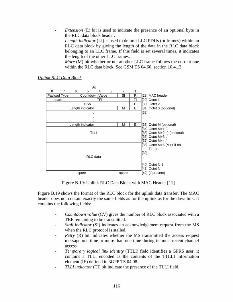
116
- Extension (E) bit is used to indicate the presence of an optional byte in the RLC data block header.
- Length indicator (LI) is used to delimit LLC PDUs (or frames) within an RLC data block by giving the length of the data in the RLC data block belonging to an LLC frame. If this field is set several times, it indicates the length of the other LLC frames.
- More (M) bit whether or not another LLC frame follows the current one within the RLC data block. See GSM TS 04.60, section 10.4.13.
Uplink RLC Data Block
Bit 8 7 6 5 4 3 2 1
Payload Type Countdown Value SI R [28] MAC header spare TFI TI [29] Octet 1
BSN E [30] Octet 2 Length indicator M E [31] Octet 3 (optional)
.
.
.
[32] . . .
Length indicator M E [33] Octet M (optional) [34] Octet M+1 \ TLLI [35] Octet M+2 } (optional) [36] Octet M+3 / [37] Octet M+4 / [38] Octet M+5 (M+1 if no
TLLI)
RLC data [39] .
.
. [40] Octet N-1 [41] Octet N spare spare [42] (if present)
Figure B.19: Uplink RLC Data Block with MAC Header [11]
Figure B.19 shows the format of the RLC block for the uplink data transfer. The MAC header does not contain exactly the same fields as for the uplink as for the downlink. It contains the following fields:
- Countdown value (CV) gives the number of RLC block associated with a TBF remaining to be transmitted.
- Stall indicator (SI) indicates an acknowledgement request from the MS when the RLC protocol is stalled.
- Retry (R) bit indicates whether the MS transmitted the access request message one time or more than one time during its most recent channel access
- Temporary logical link identity (TTLI) field identifies a GPRS user; it contains a TLLI encoded as the contents of the TTLLI information element (IE) defined in 3GPP TS 04.08.
- TLLI indicator (TI) bit indicate the presence of the TLLI field.

117
B6.3 The Control Block The RLC/MAC block used for the transfer of control message consists of a MAC header and an RLC/MAC control blocks, shown below (Figure B.20). The RLC/MAC blocks used for control are encoded using the coding scheme CS-1. The size of the RLC/MAC control block is 22 bytes; the size of the MAC header is 1 byte.
Figure B.20: RLC/MAC block structure for control message [3]
Downlink RLC/MAC Control Block The RLC/MAC control block format for the downlink direction is shown in Figure B.21. It consists of a control message contents field and an optional control header. The MAC header contains the elements as described earlier for downlink RLC data block.
Bit 8 7 6 5 4 3 2 1
Payload Type RRBP S/P USF [43] MAC header RBSN RTI FS AC [44] Octet 1 (optional)
PR TFI D [45] Octet 2 (optional) [46] Octet M
Control Message Contents
[47] . . .
[48] Octet 21 [49] Octet 22
Figure B.21: Downlink RLC/MAC control block format with MAC header [11]
The RLC/MAC header contains the following elements:
- Reduced block sequence number (RBSN), which gives the sequence number of the RLC/MAC control block.
- Radio transaction identifier (RTI), which is used to identify an RLC/MAC control message that has been segmented into two RLC/MAC control blocks.
- Final segment (FS), which indicates whether the RLC/MAC control block contains the FS of the segmented RLC/MAC control message.
- Address control (AC), which indicates the presence of an optional byte containing PR, TFI, and D fields.
MAC header
RLC/MAC control block

118
- Direction (D), which indicates the direction of the TBF identified by the TFI field.
- PR, which indicates the power reduction that has been used by the BTS to transmit the current block.
The control message field contains an RLC/MAC control message. Uplink RLC/MAC Control Block Figure B.22 below shows the format of the RLC/MAC control block for the uplink with its MAC header. The RLC/MAC control block consists of a control contents field
Bit 8 7 6 5 4 3 2 1 [50]
Payload Type spare R [51] MAC header [52] Octet 1 [53] Octet 2 [54] Octet 3
Control Message Contents
[55] . . .
[56] Octet 21 [57] Octet 22
Figure B.22: Uplink RLC/MAC control block together with its MAC header [11] The MAC header contains:
- PT, which indicates the type of data within the block. - R, which indicates whether the MS transmitted the access request
message one time or more than one time during its most recent channel access.
119
Appendix C
Sagem OTxxx Series Protocol Specifications Because the Sagem OT xxx trace mobile has its unique protocol specification, it is necessary to study its protocol specifications and frames arrangement in this series of trace mobile; this form a prelude exercise prior to the coding exercise, which will be explained in the next chapter. The Sagem trace mobiles OT 190 and OT 290 are extensively used during the debugging and the coding/decoding exercise of this project. The major difference between these two trace mobiles lies in the fact that the OT 290 is equipped with a colour screen; but both mobile support GPRS service, equipped with PC trace capabilities and as well as screen trace capabilities. It is imperative to describe, according to the GSM technical specifications (TS) 05.08 what the DSC is. The DSC The downlink signaling failure is based on the downlink signaling counter (DSC). When an MS camps on a cell, the DSC shall be initialized to a value equal to the nearest integer to 90/N; where N is the BS_PA_MFRMS parameter for that cell (see reference 1). The MS is required to attempt to decode a paging message every time its paging sub channel is active; therefore the network activates the paging sub channel for a given MS every BS_PA_MFRMS multiframes. In case discontinuous reception (DRX) split is supported, the mobile listens to its paging sub channel every 1/NDRX multiframes [13]. Thereafter, whenever the MS attempts to decode a message in its paging sub channel; if a message is successfully decoded i.e. bad frame indication =0 (BFI=0), the DSC is incremented by 1, but never beyond a maximum value (parameter of the radio configuration of the cell) , otherwise DSC is decreased by 4. When DSC≤ 0, a downlink signaling failure shall be declared and this ultimately results in cell reselection [13]. For GPRS, an MS in packet idle mode follows the same procedure. The counter DSC is initialized each time the MS leaves packet transfer mode. In case of DRX period split is supported, DSC shall be initialized to a value equal to the nearest integer to max (10, 90*NDRX), where NDRX is the average number of monitored blocks per multiframe according to its paging group.

120
C1 General Aspect of the Frame of the Trace Mobile All the exchanged frames on the serial link between the mobile and the PC is in accordance with Figure C.1 shown below:
Figure C.1: General Frame Format of the Trace Mobile [12] STX – (Start of Text): 0x02 ETX – (End of Text): 0x03 FCS – Checksum
The application ID The application ID field identifies the source or destination application of the message. Application ID field Application 0x00 OTR (Mobile Trace Tool Application) 0x01 AT commands
Total Application message length
Figure C.2: Application message length [12]
STX (1 byte)
Application ID (1 byte)
Total Application Message Length (2 bytes)
Application Message (Total Application Message Length bytes)
FCS (1 byte)
ETX (1 byte)
R High
Total application message length
8 7 6 5 4 3 2 1
Byte 1
Byte 2

121
The application message length is coded 13-bit, which implies that application message length of 8191 bytes is possible.
C2 The OTR Application Protocol
Figure C.3 below shows the general OTR frames structure:
Figure C.3: OTR Frame Structure [12] Identification The identification element identifies the precise type of each exchanged message. It consists of 2 bytes as in Figure C4.
Figure C.4: Identification Element of the OTR Frame Structure [12]
1 2 3 4 5 6 7 8
Identification (2 bytes)
Information Message Field
(variable length, max.:8189 bytes)
Type R
ext
8 7 6 5 4 3 2 1
Category
Res. Sub Type

122
The bit ext. is used in particular in command message to indicate message extension presence; this bit is used:
In GPRS RLC/MAC header command to activate downlink dummy control blocks trace.
In C/I GSM command to define frequency calculation of C/I.
Type The Type field identifies the macro type the message belongs: 0000b: Layer message trace 0001b: Quality of service (QoS) indicator 0010b: Layer state and measurement information (LSMI) 0011b: Forcing message 0100b: Mobile information message 0101b: Control message 0110b: Trace storage
Category This field consists of 2 bits [12]
Category field Signification Direction 000b Command 001b Request
PC side to MS side
010b Reply 011b Trace message 100b Information 101b Error 111b Stored trace message
MS side to PC side
110b Reserved The message categories are defined from OT user point of view as follows:
A command message is sent by the external terminal toward the mobile A request message sent by an external terminal toward the mobile. Its an
information request. It does not alter the mobile state or configuration; it expects a reply category in return.
A trace message is sent by the mobile towards an external terminal. It is a message buffered in order to increase the sequential trace order reliability ( all trace messages are written within the same buffer)

123
A reply message is sent by an MS towards an external terminal. It is sent directly towards the terminal without any buffering: hence there is no there is no notion of sequential order in replies.
An information message is sent by the MS to an external terminal. This message is sent spontaneously to inform user about internal event as “Restitution starting”, etc.
An error message is sent by the MS to an external terminal to inform it about an internal error as: “feature not supported”, “memory full”, etc.
The Sub Type The Sub Type identifies the message meaning within a given type. The sub type is defined over 5 bits. Therefore each type can be sub divided into up to 31 sub types. The 32nd (25 = 32) code, 1F (h), is reserved to indicate an unspecific sub type. Unspecific sub type has different meaning for each type. All the sub types for QoS Information messages and LSMI will are shown below: Quality of service message - 0 0000b : Retransmitted RLC Block Rate - 0 0001b : RLC/MAC Data throughput - 0 0010b : DSC Counter QoS - 0 0011b : RLT Counter QoS - 0 0100b : FER - 0 0101b : EFR state - 0 0110b : DTX state - 0 0111b : RLP Resume Rate - 0 1000b : Handover Counter - 0 1001b : Reserved value - 0 1010b : Retransmitted LLC Frame Rate - 0 1011b : LLC Data throughput - 0 1100b : Total RLC blocks transmitted - 0 1101b : Total LLC frames transmitted - 0 1110b : Downlink RLC BLER (Block Error Rate) - 0 1111b : C/I GSM - 1 0000b : AMR trace (defined in ANNEX B AMR protocol specification) Layer state and measurement information message - 0 0000b : Layer 1 information - 0 0001b : Service state - 0 0010b : Reserved for future use - 0 0011b : MAC information - 0 0100b : RLC information - 0 0101b : RR information
124
- 0 0110b : LLC information - 0 0111b : MM information - 0 1000b : GMM information - 0 1001b : SM information For full description of the Sub Types of preciously described Types, see SAGEM document referenced in the reference section.
Information Message Field This depends on message identification in particular on the type field. The one of the sub objective of this project is to develop the DSC screen, the field for QoS indicator messages, down to the trace message for DSC counter and Layer State and Measurement Information (LSMI) messages will only be considered down to the MAC Information trace message.
C3 QoS Messages
QoS messages are identified are identified by type field set to “0x01”. The QoS messages are sent either upon reception of a command or, if activated, when one of the concerned parameter changes. Command 6 The QoS command messages is sent by the PC to request the trace mobile to send
QoS information messages. 7 The Sub Type field (in the identification field) of QoS command messages shall be
set to “11111b”. 8 The information field for QoS is the same as layer message command [12:22] part of
the referenced document). Each of the following binary values is defined as 2(Sub Type) with the corresponding Sub Type [12:18-19].
The possible values of the configuration bits for QoS messages are: High low 0000 0000 0000 0000 0000 0000 0000 0001b : Retransmitted RLC Block Rate 0000 0000 0000 0000 0000 0000 0000 0010b : RLC/MAC Data throughput 0000 0000 0000 0000 0000 0000 0000 0100b : DSC Counter QoS 0000 0000 0000 0000 0000 0000 0000 1000b : RLT Counter QoS

125
0000 0000 0000 0000 0000 0000 0001 0000b : FER 0000 0000 0000 0000 0000 0000 0010 0000b : EFR state 0000 0000 0000 0000 0000 0000 0100 0000b : DTX state 0000 0000 0000 0000 0000 0000 1000 0000b : RLP Resume Rate 0000 0000 0000 0000 0000 0001 0000 0000b : Activate Handover Counter 0000 0000 0000 0000 0000 0010 0000 0000b : Reset Handover Counter 0000 0000 0000 0000 0000 0100 0000 0000b : Retransmitted LLC Frame Rate 0000 0000 0000 0000 0000 1000 0000 0000b : LLC Data throughput 0000 0000 0000 0000 0001 0000 0000 0000b : Total RLC blocks transmitted 0000 0000 0000 0000 0010 0000 0000 0000b : Total LLC frames transmitted 0000 0000 0000 0000 0100 0000 0000 0000b : Downlink RLC BLER (Block
Error Rate) 0000 0000 0000 0000 1000 0000 0000 0000b : C/I GSM 0000 0000 0000 0001 0000 0000 0000 0000b : AMR trace (defined in ANNEX N° AMR trace specification) Trace messages The general structure of the information field for QoS trace messages is as follows, a more detailed for the DSC counter message is given as well: Figure C.5: General frame structure of the information field for QoS trace Messages [12]
Figure C.6: The DSC counter trace message [12] The DSC trace message is sent only in idle mode.
QoS Information Field Length
QoS Information Field (MSB)
………………….
QoS Information Field (LSB)
Byte 1
Byte 2
…….
Byte n
0x02
Max. DSC Counter
Current DSC Counter
Byte 1
Byte 2
Byte 3
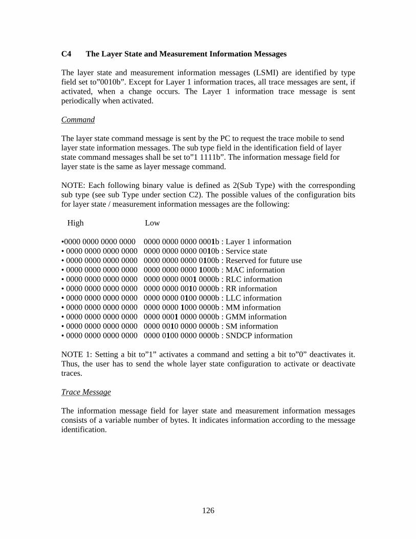
126
C4 The Layer State and Measurement Information Messages
The layer state and measurement information messages (LSMI) are identified by type field set to”0010b”. Except for Layer 1 information traces, all trace messages are sent, if activated, when a change occurs. The Layer 1 information trace message is sent periodically when activated. Command The layer state command message is sent by the PC to request the trace mobile to send layer state information messages. The sub type field in the identification field of layer state command messages shall be set to”1 1111b”. The information message field for layer state is the same as layer message command. NOTE: Each following binary value is defined as 2(Sub Type) with the corresponding sub type (see sub Type under section C2). The possible values of the configuration bits for layer state / measurement information messages are the following: High Low •0000 0000 0000 0000 0000 0000 0000 0001b : Layer 1 information • 0000 0000 0000 0000 0000 0000 0000 0010b : Service state • 0000 0000 0000 0000 0000 0000 0000 0100b : Reserved for future use • 0000 0000 0000 0000 0000 0000 0000 1000b : MAC information • 0000 0000 0000 0000 0000 0000 0001 0000b : RLC information • 0000 0000 0000 0000 0000 0000 0010 0000b : RR information • 0000 0000 0000 0000 0000 0000 0100 0000b : LLC information • 0000 0000 0000 0000 0000 0000 1000 0000b : MM information • 0000 0000 0000 0000 0000 0001 0000 0000b : GMM information • 0000 0000 0000 0000 0000 0010 0000 0000b : SM information • 0000 0000 0000 0000 0000 0100 0000 0000b : SNDCP information NOTE 1: Setting a bit to”1” activates a command and setting a bit to”0” deactivates it. Thus, the user has to send the whole layer state configuration to activate or deactivate traces. Trace Message The information message field for layer state and measurement information messages consists of a variable number of bytes. It indicates information according to the message identification.

127
C5 MAC Information
The information message field for MAC information messages consists of 8 bytes and it is shown in Figure C.7 below:
Figure C.7: Information message field for MAC Information trace message.
VI_LEV_TN and I_LEVEL_TN0 to I_LEVEL_TN7 are reserved for future use; uplink and downlink timeslot allocation bytes are defined like a bitmap. All the description of the fields in this trace message can be found in [12].

128
Appendix D
Decoding of GSM L3, GPRS L3 and RLC/MAC Control Messages D1 Decoding of GSM Layer 3 RR Messages D1.1 Paging Request Type 1
This message is sent on the CCCH by the network to up to two mobile stations. It may be sent to a mobile station in idle mode to trigger channel access. It may be sent to a mobile station in packet idle mode to transfer MM information (i.e. trigger of cell update procedure). The mobile stations are identified by their TMSI/P-TMSI or IMSI. See table 9.22/3GPP TS 04.08. The L2 pseudo length of this message is the sum of lengths of all information elements present in the message except the P1 Rest Octets and L2 Pseudo Length information elements. Message type: PAGING REQUEST TYPE 1
Significance: dual
Direction: network to mobile station
Table 9.22/3GPP TS 04.08: PAGING REQUEST TYPE 1 message content
IEI Information element Type / Reference Presence Format
length
L2 Pseudo Length L2 Pseudo Length M V 1 10.5.2.19 RR management Protocol Discriminator M V 1/2 Protocol Discriminator 10.2 Skip Indicator Skip Indicator M V 1/2 10.3.1 Paging Request Type 1 Message Type M V 1 Message Type 10.4 Page Mode Page Mode M V 1/2 10.5.2.26 Channels Needed for Channel Needed M V 1/2 Mobiles 1 and 2 10.5.2.8 Mobile Identity 1 Mobile Identity M LV 2-9 10.5.1.4 17 Mobile Identity 2 Mobile Identity O TLV 3-10 10.5.1.4 P1 Rest Octets P1 Rest Octets M V 0-17 10.5.2.23

129
Message Content RR PAGING_REQUEST_TYPE_1
15 06 21 00 01 F0 2B 2B 2B 2B 2B 2B 2B 2B 2B 2B 2B 2B 2B 2B 2B 2B 2B
Decoding Hex Binary Decode Information Element Interpretation 15 0001-0101 000101 L2 Pseudo Length Message Length = 5 (no of
octets following this to be interpreted, rest octet not included)
06 0000-0110 0110 0000
Protocol Discriminator Skip Indicator
Radio Resource management message Message not to be ignored
21 0010-0001 00100-001 Message Type PAGING REQUEST TYPE 1 00 0000-0000 0000
0000
Page Mode Channels Needed
Bits (4 3) = 00 Spare Bits (2 1) = 00 Normal Paging 00 = Any Channel
01 0000-0001 00000001 Length of Mobile Identity content = 1
F0 1111-0000 1111 000 0
Mobile Identity
Identity digit = 15 digits (Bits 1-3) = No Identity (Bit 4) = even number of identity
2B 0010-1011 2B 0010-1011 2B 0010-1011 2B 0010-1011 2B 0010-1011 2B 0010-1011 2B 0010-1011 2B 0010-1011 2B 0010-1011 2B 0010-1011 2B 0010-1011 2B 0010-1011 2B 0010-1011 2B 0010-1011 2B 0010-1011 2B 0010-1011 2B 0010-1011
Padding Bits
P1 Rest Octets GSM 04.08 section 10.5.2.23

130
D1.2 Immediate assignment This message is sent on the CCCH by the network to the mobile station in idle mode to change the channel configuration to a dedicated configuration while staying in the same cell or to the mobile station in packet idle mode to change the channel configuration to either an uplink or a downlink packet data channel configuration in the cell. See table 9.18/3GPP TS 04.08. The L2 pseudo length of this message is the sum of lengths of all information elements present in the message except the IA Rest Octets and L2 Pseudo Length information elements.
Message type: IMMEDIATE ASSIGNMENT
Significance: dual
Direction: network to mobile station
Table 9.18/3GPP TS 04.08: IMMEDIATE ASSIGNMENT message content
IEI Information element Type / Reference Presence Format
length
L2 Pseudo Length L2 Pseudo Length M V 1 10.5.2.19 RR management Protocol Discriminator M V 1/2 Protocol Discriminator 10.2 Skip Indicator Skip Indicator M V 1/2 10.3.1 Immediate Assignment Message Type M V 1 Message Type 10.4 Page Mode Page Mode M V 1/2 10.5.2.26 Dedicated mode or TBF Dedicated mode or TBF M V 1/2 10.5.2.25b Channel Description Channel Description C V 3 10.5.2.5 Packet Channel
Description Packet Channel Description
C V 3
10.5.2.25a Request Reference Request Reference M V 3 10.5.2.30 Timing Advance Timing Advance M V 1 10.5.2.40 Mobile Allocation Mobile Allocation M LV 1-9 10.5.2.21 7C Starting Time Starting Time O TV 3 10.5.2.38 IA Rest Octets IA Rest Octets M V 0-11 10.5.2.16

131
Message Content RR IMMEDIATE_ASSIGNMENT 2D 06 3F 10 0F A8 04 78 42 12 01 00 CA 00 33 72 2B 2B 2B 2B 2B 2B 2B Decoding Hex
Binary Decode Information Element Interpretation
2D 00101101 001011 L2 Pseudo Length Message Length = 11 (no of octets to be interpreted, following this. The rest octets not included)
06 00000110 0110 0000
Protocol Discriminator Skip Indicator
Radio Resource management messages Message not to be ignored unless ignored for any other reasons
3F 00111111 00111-111 Message type Immediate Assignment 10 00010000 0000
0001
Page Mode Dedicated Mode or TBF
(bits 2 1) = 00 Normal Paging (bits 4 3) = 00 Spare 1 This message assign a TBF 0 No meaning 0 No meaning 0 Spare
0F 00001111 00001 111
Channel Type and TDMA offset = TCH/F+ACCHs Timeslot Number (TN) = 7. GSM 05.10 section 3.1
A8 10101000 101 0 10 00
04 00000100
Channel Description Training Sequence Code (TSC) = 5
Hopping Channel (H) = 0 Single RF Channel Spare ??? GSM 04.08 section 10.5.2.5 ARFN The ARFN is the combination of these bits (in this octet) with all the bits in the next octet. ⇒ ARFN = 4

132
78 01111000 01111xxx Random Access (RA) Information One phase packet access with request for single timeslot uplink transmission; one PDCH is needed
42 01000010 12 00010010
01000 010000 10010
Request Reference
T1′ = 8 T3 = 16 T2 = 18
01 00000001 00 000001
Timing Advance Spare bits Timing Advance value 48/13 s =3.69 s
00 00000000 Length of mobile allocation content = 0
CA 11001010 00 00000000 33 00110011 72 01110010
Mobile Allocation
2B 00101011 2B 00101011 2B 00101011 2B 00101011 2B 00101011 2B 00101011 2B 00101011
IA Rest Octets
D1.3 RR System Information Type 4
This message is sent on the BCCH by the network giving information on control of the RACH, the location area identification, the cell identity and various other information about the cell. See table 9.33/3GPP TS 04.08. Special requirements for the transmission of this message apply, see 3GPP TS 05.02. The L2 pseudo length of this message is the sum of lengths of all information elements present in the message except the SI 4 Rest Octets and L2 Pseudo Length information elements.
Message type: SYSTEM INFORMATION TYPE 4
Significance: dual
Direction: network to mobile station

133
Table 9.33/3GPP TS 04.08: SYSTEM INFORMATION TYPE 4 message content
IEI Information element Type / Reference Presence Format length L2 Pseudo Length L2 Pseudo Length M V 1 10.5.2.19 RR management Protocol Discriminator M V 1/2 Protocol Discriminator 10.2 Skip Indicator Skip Indicator M V 1/2 10.3.1 System Information Message Type M V 1 Type 4 Message Type 10.4 Location Area Location Area M V 5 Identification Identification 10.5.1.3 Cell Selection Cell Selection Parameters M V 2 Parameters 10.5.2.4 RACH Control
Parameters RACH Control Parameters M V 3
10.5.2.29 64 CBCH Channel Channel description O TV 4 Description 10.5.2.5 72 CBCH Mobile
Allocation Mobile Allocation C TLV 3-6
10.5.2.21 SI 4 Rest Octets SI 4 Rest Octets M V 0-10 10.5.2.35 Message Content RR SYSTEM_INFORMATION_TYPE_4
31 06 1C 02 F8 01 04 4C A5 00 BD 00 00 80 00 43 2B 2B 2B 2B 2B 2B 2B
Decoding
Hex
Binary Decode Information Element
Interpretation
31 00110001 001100 L2 Pseudo Length
Message Length = 12 (no of octets to be interpreted, following this. The rest octets are excluded)
06 00000110 0110 0000
Protocol Discriminator Skip Indicator
Radio Resource management messages Message should not be ignored
1C 00011100 00011-100
Message Type System Information Type 4
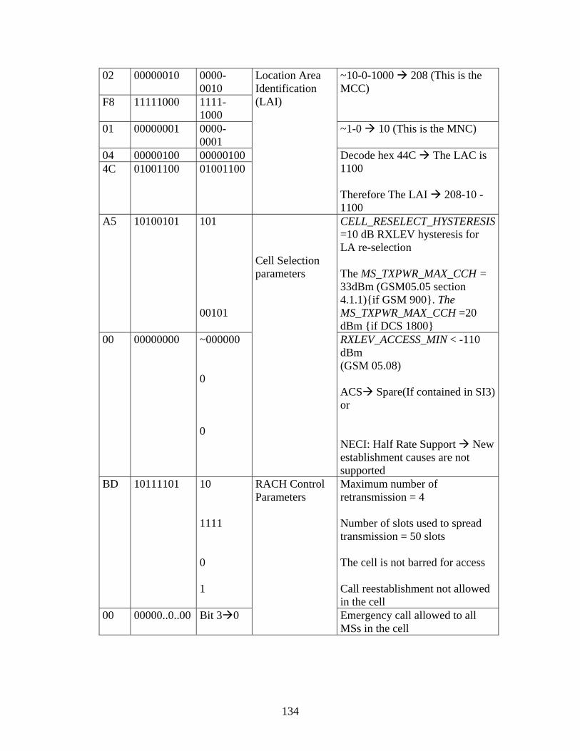
134
02 00000010 0000-0010
F8 11111000 1111-1000
~10-0-1000 208 (This is the MCC)
01 00000001 0000-0001
~1-0 10 (This is the MNC)
04 00000100 000001004C 01001100 01001100
Location Area Identification (LAI)
Decode hex 44C The LAC is 1100 Therefore The LAI 208-10 - 1100
A5 10100101 101 00101
CELL_RESELECT_HYSTERESIS =10 dB RXLEV hysteresis for LA re-selection The MS_TXPWR_MAX_CCH = 33dBm (GSM05.05 section 4.1.1){if GSM 900}. The MS_TXPWR_MAX_CCH =20 dBm {if DCS 1800}
00 00000000 ~000000 0 0
Cell Selection parameters
RXLEV_ACCESS_MIN < -110 dBm (GSM 05.08) ACS Spare(If contained in SI3) or NECI: Half Rate Support New establishment causes are not supported
BD 10111101 10 1111 0 1
Maximum number of retransmission = 4 Number of slots used to spread transmission = 50 slots The cell is not barred for access Call reestablishment not allowed in the cell
00 00000..0..00 Bit 3 0
RACH Control Parameters
Emergency call allowed to all MSs in the cell

135
00 00000000 For bit 1 (of octet above except bit 3, which has been interpreted) up to bit 8 of this octet coded “0”; this implies that access is not barred [Access Control, AC CN bit are all coded “0”]
80 10000000 00 00000000 43 01000011 2B 00101011 2B 00101011 2B 00101011 2B 00101011 2B 00101011 2B 00101011 2B 00101011
SI 4 Rest Octet
D1.4 System information type 3 This message is sent on the BCCH by the network giving information of control on the RACH, the location area identification, the cell identity and various other information about the cell. See table 9.32/3GPP TS 04.08. Special requirements for the transmission of this message apply, see 3GPP TS 05.02. This message has a L2 Pseudo Length of 18.
Message type: SYSTEM INFORMATION TYPE 3
Significance: dual
Direction: network to mobile station
Table 9.32/3GPP TS 04.08: SYSTEM INFORMATION TYPE 3 message content
IEI Information element Type / Reference Presence Format length L2 Pseudo Length L2 Pseudo Length M V 1 10.5.2.19 RR management Protocol Discriminator M V 1/2 Protocol Discriminator 10.2 Skip Indicator Skip Indicator M V 1/2 10.3.1 System Information Message Type M V 1 Type 3 Message Type 10.4 Cell Identity Cell Identity M V 2 10.5.1.1 Location Area Location Area M V 5 Identification Identification 10.5.1.3 Control Channel Control Channel M V 3 Description Description 10.5.2.11 Cell Options Cell Options (BCCH) M V 1 10.5.2.3 Cell Selection Cell Selection Parameters M V 2 Parameters 10.5.2.4

136
RACH Control Parameters RACH Control Parameters M V 3 10.5.2.29 SI 3 Rest Octets SI 3 Rest Octets M V 4 10.5.2.34 Message Content RR SYSTEM_INFORMATION_TYPE_3 49 06 1B 2F 28 02 F8 01 04 4C 68 03 1E 54 A0 05 BD 00 00 88 00 40 4B Decoding Hex
Binary Decode Information Element Interpretation
49 01001001 010010 L2 Pseudo Length Message Length = 18 (no of octets to be interpreted, the L2 pseudo length and the rest octets are excluded.
06 00000110 0110 0000
Protocol Discriminator Skip Indicator
Radio Resource management messages Message received not to be ignored
1B 00011011 00011-011 Message Type System Information Type 3 2F 00101111 28 00101000
~10111100101000 Cell Identity The cell identity (CI) is a 16-bit identifier (2F28) = 12072
02 00000010 0010 0000
F8 11111000 ~1000
The 1st ,2nd and 3rd digit of the MCC are thus decoded (~10-0-1000) from the first & second octets = 208
01 00000001 0001 0000
The MNC 1st and 2nd digit is ~1-0 10
04 00000100 4C 01001100
~10001001100
Location Area Identification (LAI)
The LAC is the combination of 4th and the 5th octet 1100. The LAI is 208-10-1100
68 01101000 0 1 101 000
Control Channel Description
Spare MSs in the cell shall apply IMSI attach and detach procedure Number of blocks reserved for access grant = 5 One basic physical channel used for CCCH, not combined with SDCCHs

137
03 00000011 ~011 4 multiframes period for transmission of PAGING REQUEST messages to the same paging subgroup; i.e. BS_PA_MFRMS= 4
1E 00011110 ~11110
The timeout value for periodic updating is 30 decihours = 180 minutes
54 01010100 0 1 01 0100
Cell Options (BCCH) Spare Power control indicator (PWRC) is set Discontinuous transmission (DTX) MSs shall use uplink discontinuous transmission RADIO_LINK_TIMEOUT times = 20
A0 10100000 101 00000
10 dB RXLEV hysteresis for LA re-selection. The MS_TXPWR_MAX_CCH = 39dBm (GSM05.05 section 4.1.1){if GSM 900}. The MS_TXPWR_MAX_CCH =30 dBm {if DCS 1800}
05 00000101 0 0 000101
Cell Selection Parameters
Spare New establishment cause are not supported Minimum received signal level at the MS required for access to the system = 5 -106 dBm to –105 dBm (GSM 05.08 section 8.1.4)
BD 10111101 10 1111 0 1
Maximum 4 retransmissions Number of slots used to spread transmission = 50 slots Cell is not barred Call reestablishment not allowed in the cell
00 00000000 0
RACH Control Parameters
Bit 3 Emergency call allowed in the cell to all MSs

138
00 00000000 For the Access Control Class N (AC CN), where N =0, 1, 2…15 N is coded “0” No class of MS is barred for access {Table 10.5.68, GSM 04.08}
88 10001000 00 00000000 40 01000000 4B 01001011
SI 3 Rest Octets
D2 GPRS Layer 3 and RLC/MAC Control Messages The following traces were obtained and decoded after performing GPRS attach and initiations of PDP context activation were done.
GPRS Layer 3 Messages D2.1 Activate PDP Context Request This message is sent by the MS to the network to request activation of a PDP context. See table 9.5.1/3GPP TS 04.08.
Message type: ACTIVATE PDP CONTEXT REQUEST
Significance: global
Direction: MS to network
Table 9.5.1/3GPP TS 04.08: ACTIVATE PDP CONTEXT REQUEST message content
IEI Information Element Type/Reference Presence Format Length Protocol discriminator Protocol discriminator
10.2 M V 1/2
Transaction identifier
Transaction identifier 10.3.2
M V 1/2
Activate PDP context request message identity
Message type 10.4
M V 1
Requested NSAPI Network service access point identifier 10.5.6.2
M V 1

139
Requested LLC SAPI LLC service access point identifier 10.5.6.9
M V 1
Requested QoS Quality of service 10.5.6.5
M LV 4
Requested PDP address Packet data protocol address 10.5.6.4
M LV 3 - 19
28 Access point name Access point name 10.5.6.1
O TLV 3 - 102
27 Protocol configuration options
Protocol configuration options 10.5.6.3
O TLV 3 - 253
Message Content
SM ACTIVATE_PDP_CONTEXT_REQUEST
0A 41 05 05 03 03 00 00 02 01 21 28 07 06 77 65 62 73 66 72 27 22 80 C0 23 0B 01 02 00 0B 05 6A 61 6D 65 73 00 80 21 10 01 01 00 10 81 06 00 00 00 00 83 06 00 00 00 00
Decoding Hex
Binary Decode Information Element Interpretation
0A 00001010 1010 0 000
Protocol Discriminator Transaction Identifier
Session Management messages The message is sent from the side that originates T1 T1 value 0 (GSM 04.07 section 11.2.3.1.3)
41 01000001 01000-001 Message Type Activate PDP context request 05 00000101 0000
0101
Network Service Access Point Identifier (NSAPI)
Spare bits (NSAPI value) NSAPI 5
05 00000101 0000 0101
LLC Service Access Point Identifier
Spare (LLC SAPI value) SAPI 5
03 00000011
(Length of quality of service IE) 3

140
03 00000011 00 000 011
Spare (Delay class) Subscribed delay class (Reliability class) Unacknowledged GTP and LLC; Acknowledged RLC, Protected data
00 00000000 000 0 0000
(Precedence class) Subscribed precedence Spare (Peak Throughput) Subscribed peak Throughput
00 00000000 000 00000
Quality of Service
Spare (Mean throughput)Subscribed mean throughput.
02 00000010 00000010 Length of PDP address contents = 2
01 00000001 0000 0001
Spare (PDP type organisation) IETF allocated address
21 00100001 00100001
Packet Data Protocol Address
(PDP type number) This is IPv4 address
28 00101000 00101000 Access point name IEI 07 00000111 Length of access point name
contents = 7 06 00000110 ACK 77 01110111 W 65 01100101 E 62 01100010 B 73 01110011 S 66 01100110
Access Point Name
F
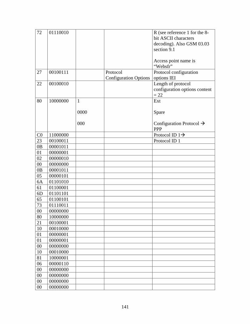
141
72 01110010 R (see reference 1 for the 8-bit ASCII characters decoding). Also GSM 03.03 section 9.1 Access point name is “Websfr”
27 00100111 Protocol Configuration Options
Protocol configuration options IEI
22 00100010 Length of protocol configuration options content = 22
80 10000000 1 0000 000
Ext Spare Configuration Protocol PPP
C0 11000000 Protocol ID 1 23 00100011 Protocol ID 1 0B 00001011 01 00000001 02 00000010 00 00000000 0B 00001011 05 00000101 6A 01101010 61 01100001 6D 01101101 65 01100101 73 01110011 00 00000000 80 10000000 21 00100001 10 00010000 01 00000001 01 00000001 00 00000000 10 00010000 81 10000001 06 00000110 00 00000000 00 00000000 00 00000000 00 00000000

142
83 10000011 06 00000110 00 00000000 00 00000000 00 00000000 00 00000000
D2.2 Activate PDP Context Accept
This message is sent by the network to the MS to acknowledge activation of a PDP context. See table 9.5.2/3GPP TS 04.08. Message type: ACTIVATE PDP CONTEXT ACCEPT
Significance: global
Direction: network to MS
Table 9.5.2/3GPP TS 04.08: ACTIVATE PDP CONTEXT ACCEPT message content
IEI Information Element Type/Reference Presence Format Length Protocol discriminator Protocol discriminator
10.2 M V 1/2
Transaction identifier
Transaction identifier 10.3.2
M V 1/2
Activate PDP context accept message identity
Message type 10.4
M V 1
Negotiated LLC SAPI LLC service access point identifier 10.5.6.9
M V 1
Negotiated QoS Quality of service 10.5.6.5
M LV 4
Radio priority Radio priority 10.5.7.2
M V 1/2
Spare half octet Spare half octet 10.5.1.8
M V 1/2
2B PDP address Packet data protocol address 10.5.6.4
O TLV 4 - 20
27 Protocol configuration options
Protocol configuration options 10.5.6.3
O TLV 3 - 253
Message Content SM ACTIVATE_PDP_CONTEXT_ACCEPT 8A 42 05 03 23 43 1F 04 2B 06 01 21 0A CE 96 10 27 14 80 80 21 10 03 01 00 10 81 06 AC 14 02 0A 83 06 AC 14 02 27

143
Hex
Binary Decode Information Element Interpretation
8A 10001010 1010 1 000
Protocol Discriminator Transaction Identifier
Session Management messages (T1 flag) The message is sent to the side that originates it (T1 value) T1 value 0
42 01000010 Message Type Activate PDP context accept 05 00000101 0000
0101
LLC Service Access Point Identifier
Spare (LLC SAPI value) 5
03 00000011 00000011 Length of QoS 3 23 00100011 00
100 011
Spare (Delay class) Delay class 4 (best effort) (Reliability class) Unacknowledged GTP and LLC; Acknowledged RLC, Protected data
43 01000011 0100 0 011
(Peak throughput) Up to 8 000 octet/s Spare (Precedence class ) Low priority
1F 00011111 000 11111
Quality of Service (QoS)
Spare (Mean throughput) Best effort
04 00000100 0000 0 100
Radio priority
Spare half octet Spare (Radio priority level value) Priority level 4 (lowest)
2B 00101011 101011 Packet data protocol address IEI = 2B
06 00000110 110
Length of PDP address contents= 6
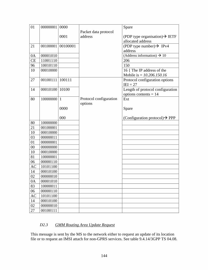
144
01 00000001 0000 0001
Spare (PDP type organisation) IETF allocated address
21 00100001 00100001 (PDP type number) IPv4 address
0A 00001010 (Address information) 10 CE 11001110 206 96 10010110 150 10 00010000
Packet data protocol address
16 { The IP address of the Mobile is = 10.206.150.16
27 00100111 100111 Protocol configuration options IEI = 27
14 00010100 10100 Length of protocol configuration options contents = 14
80 10000000 1 0000 000
Ext Spare (Configuration protocol) PPP
80 10000000 21 00100001 10 00010000 03 00000011 01 00000001 00 00000000 10 00010000 81 10000001 06 00000110 AC 10101100 14 00010100 02 00000010 0A 00001010
Protocol configuration options
83 10000011 06 00000110 AC 10101100 14 00010100 02 00000010 27 00100111
D2.3 GMM Routing Area Update Request
This message is sent by the MS to the network either to request an update of its location file or to request an IMSI attach for non-GPRS services. See table 9.4.14/3GPP TS 04.08.

145
Message type: ROUTING AREA UPDATE REQUEST
Significance: dual
Direction: MS to network
Table 9.4.14/3GPP TS 04.08: ROUTING AREA UPDATE REQUEST message content
IEI Information Element Type/Reference Presence Format Length Protocol discriminator Protocol discriminator
10.2 M V 1/2
Skip indicator Skip indicator 10.3.1
M V 1/2
Routing area update request message identity
Message type 10.4
M V 1
Update type Update type 10.5.5.18
M V 1/2
GPRS ciphering key sequence number
Ciphering key sequence number 10.5.1.2
M V 1/2
Old routing area identification
Routing area identification 10.5.5.15
M V 6
MS Radio Access capability
MS Radio Access capability 10.5.5.12a
M LV 6 - 13
19 Old P-TMSI signature P-TMSI signature 10.5.5.8
O TV 4
17 Requested READY timer value
GPRS Timer 10.5.7.3
O TV 2
27 DRX parameter DRX parameter 10.5.5.6
O TV 3
9- TMSI status TMSI status 10.5.5.4
O TV 1
31 MS network capability MS network capability 10.5.5.12
O TLV 3-4
Message Content GMM ROUTING_AREA_UPDATE_REQUEST (MS-BS)
08 08 50 02 F8 01 04 4C 03 09 14 33 82 29 1D 89 89 28 00 19 50 0D BA 27 08 00
Decoding Hex
Binary Decode Information Element Interpretation
08 00001000 1000 Protocol Discriminator Mobility Management

146
0000
Skip Indicator
messages for GPRS services Message received with this code shall not be ignored
08 00001000 00001000 Message Type Routing area update request 50 01010000 0
000 101
Update Type Ciphering key sequence number
Spare (Update value type) RA updating (key sequence) = 5
02 00000010 0010 0000
MCC digit 1 = 2 MCC digit 2 = 0
F8 11111000 1000 MCC digit 3 = 8 01 00000001 0001
0000
MNC digit 1 = 1 MNC digit 2 = 0
04 00000100 00000100- 4C 01001100 01001100
The LAC = 1100
03 00000011 11
Routing Area Identification
The RAC = 3 09 00001001 MS Radio Access
Capability Length of MS network capability contents = 9
14 00010100 MS network capability value 33 00110011 82 10000010 29 00101001 1D 00011101 89 10001001 89 10001001 28 00101000 00 00000000 19 00011001 00011001 P-TMSI signature IEI = 19 50 01010000 0D 00001101 BA 10111010
P-TMSI signature (P-TMSI signature value) 331194???
27 00100111 100111 DRX parameter IEI 27 08 00001000 1000
SPLIT PG CYCLE CODE = 8 the SPLIT PG CYCLE value
is 8
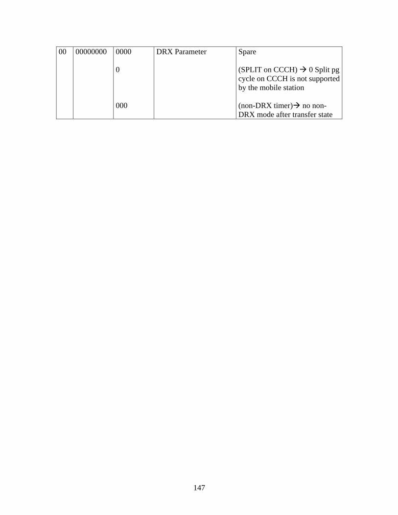
147
00 00000000 0000 0 000
DRX Parameter Spare (SPLIT on CCCH) 0 Split pg cycle on CCCH is not supported by the mobile station (non-DRX timer) no non-DRX mode after transfer state

148
- D2.4 GMM Routing Area Update Accept
This message is sent by the network to the MS to provide the MS with GPRS mobility management related data in response to a routing area update request message. See table 9.4.15/3GPP TS 04.08. Message type: ROUTING AREA UPDATE ACCEPT
Significance: dual
Direction: network to MS
Table 9.4.15/3GPP TS 04.08: ROUTING AREA UPDATE ACCEPT message content
IEI Information Element Type/Reference Presence Format Length Protocol discriminator Protocol discriminator
10.2 M V 1/2
Skip indicator Skip indicator 10.3.1
M V 1/2
Routing area update accept message identity
Message type 10.4
M V 1
Force to standby Force to standby 10.5.5.7
M V 1/2
Update result Update result 10.5.5.17
M V 1/2
Periodic RA update timer GPRS Timer 10.5.7.3
M V 1
Routing area identification Routing area identification 10.5.5.15
M V 6
19 P-TMSI signature P-TMSI signature 10.5.5.8
O TV 4
18 Allocated P-TMSI Mobile identity 10.5.1.4
O TLV 7
23 MS identity Mobile identity 10.5.1.4
O TLV 7-10
26 Receive N-PDU Numbers Receive N-PDU Number list 10.5.5.11
O TLV 4 - 19
17 Negotiated READY timer value
GPRS Timer 10.5.7.3
O TV 2
25 GMM cause GMM cause 10.5.5.14
O TV 2
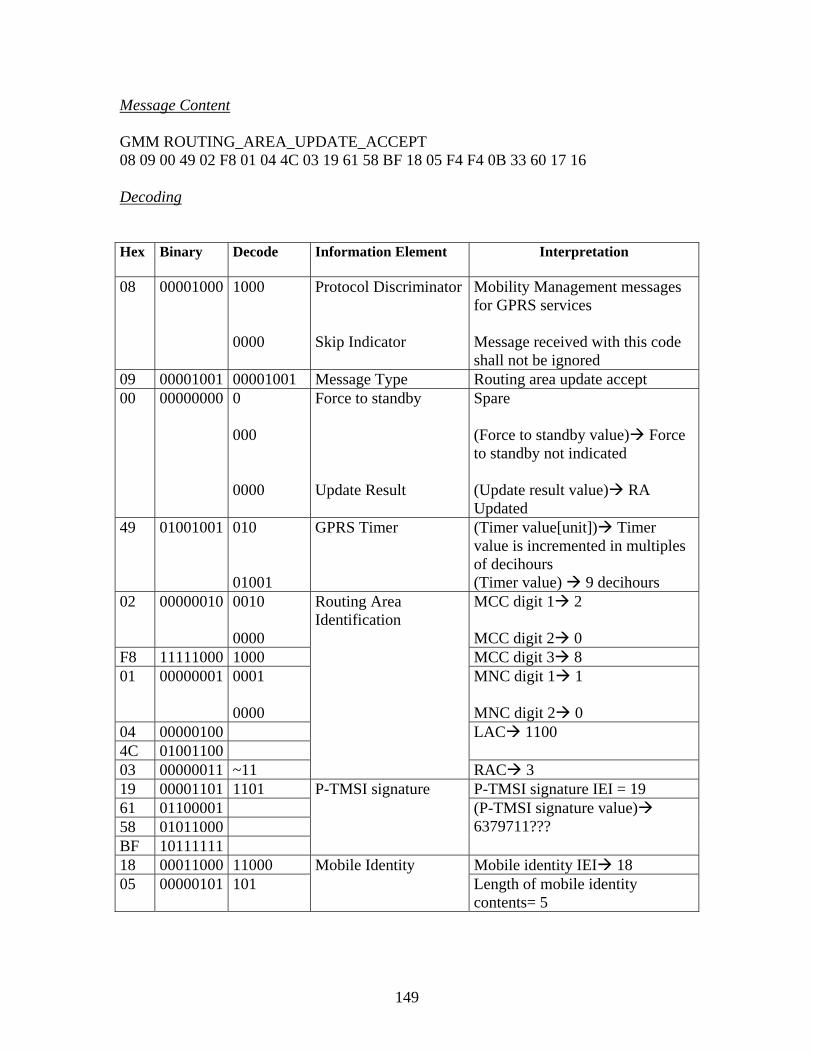
149
Message Content GMM ROUTING_AREA_UPDATE_ACCEPT 08 09 00 49 02 F8 01 04 4C 03 19 61 58 BF 18 05 F4 F4 0B 33 60 17 16 Decoding Hex
Binary Decode Information Element Interpretation
08 00001000 1000 0000
Protocol Discriminator Skip Indicator
Mobility Management messages for GPRS services Message received with this code shall not be ignored
09 00001001 00001001 Message Type Routing area update accept 00 00000000 0
000 0000
Force to standby Update Result
Spare (Force to standby value) Force to standby not indicated (Update result value) RA Updated
49 01001001 010 01001
GPRS Timer (Timer value[unit]) Timer value is incremented in multiples of decihours (Timer value) 9 decihours
02 00000010 0010 0000
MCC digit 1 2 MCC digit 2 0
F8 11111000 1000 MCC digit 3 8 01 00000001 0001
0000
MNC digit 1 1 MNC digit 2 0
04 00000100 4C 01001100
LAC 1100
03 00000011 ~11
Routing Area Identification
RAC 3 19 00001101 1101 P-TMSI signature IEI = 19 61 01100001 58 01011000 BF 10111111
P-TMSI signature (P-TMSI signature value) 6379711???
18 00011000 11000 Mobile identity IEI 18 05 00000101 101
Mobile Identity Length of mobile identity contents= 5

150
F4 11110100 100 0 1111
Type of identity = TMSI/P-TMSI
Even number of identity digits (and also when TMSI/P-TMSI is used)
This is an end mark code which confirms that the number of identity digits is even
Identity digit 1 = 15 F4 11110100 0100
1111
Identity digit 2 = 4 Identity digit 3 = 15
0B 00001011 1011 0000
Identity digit 4 = 11 Identity digit 5 = 0
33 00110011 0011 0011
Identity digit 6= 3 Identity digit 7 = 3
60 01100000 0000 0110
Identity digit 8 = 0 Identity digit 9 = 6
17 00010111 GPRS Timer GPRS Timer IEI 17 16 00010110 000
10110
(Timer value unit) Value is incremented in multiples of 2 seconds Timer value = 22 seconds
RLC/MAC Control Messages
D2.5 Packet Uplink Assignment
This message is sent on the PCCCH or PACCH by the network to the mobile station to assign uplink resources. The mobile station may be addressed by TFI, TQI, or Packet Request Reference depending upon the procedure used. A mobile allocation or reference frequency list received as part of this assignment message shall be valid until new assignment is received or each TBF of the MS are terminated. Message type: PACKET UPLINK ASSIGNMENT
Direction: network to mobile station

151
Classification: non-distribution message PACKET_UPLINK_ASSIGNMENT MS <----------------------------------------------------------- BS
4728 2D 36 71 17 98 02 1A 2B 2B 2B 2B 2B 2B 2B 2B 2B 2B 2B 2B 2B 2B Decoding
Hex
Binary Decoding Field Name Interpretation
47 0100-0111
01
00 0
111
Payload type
RRBP
S/P
USF
RLC/MAC control block without optional octets
GSM TS 04.60 section 10.4.7
RRBP = 0 GSM TS 04.60 section 10.4.5
S/P = 0 RRBP = 0
GSM TS 04.60 section 10.4.4
USF = 7 (FREE) GSM TS 04.60 section 10.4.1
28 0010-1000
001010
00
Message Type
PAGE MODE
Packet Uplink Assignment message
GSM TS 04.60 section 11.2.0.1
Normal Paging
GSM TS 04.60 section 12.20 2D 0010-
1101 0
01<01101>
Persistence Level
Global TFI (Downlink TFI)
Persistence Level is absent GSM TS 04.60 section 12.14
Downlink TFI = 13
36
0011-0110
0 01 1
Message escape CHANNEL_CODING_ COMMAND TLLI_Block_chan_Cod
Message escape GSM TS 04.60 section 11.2.29
MS shall use CS-2 when transmitting data on the
uplink. GSM TS 04.60 section 11.2.29
TLLI_Block_Channel_Coding =1, MS shall use CS as specified by Chan_Coding_Command
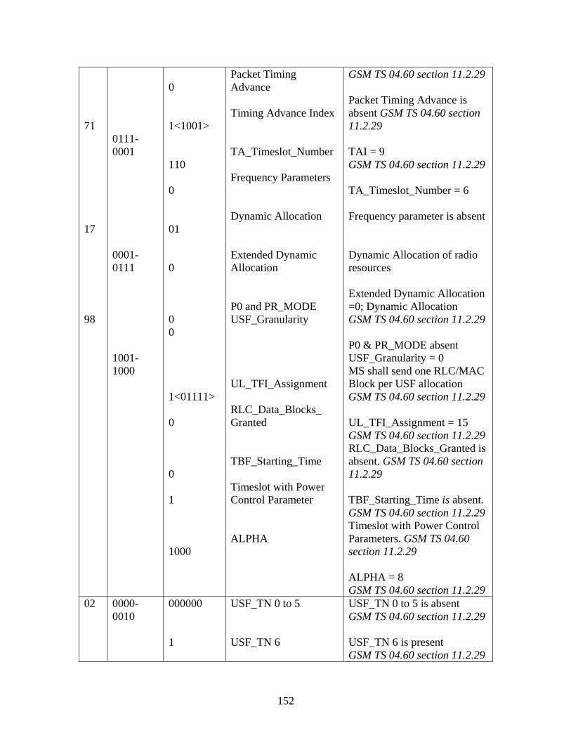
152
71 17 98
0111-0001 0001-0111 1001-1000
0 1<1001> 110 0 01 0 0 0 1<01111> 0 0 1 1000
Packet Timing Advance Timing Advance Index TA_Timeslot_Number Frequency Parameters Dynamic Allocation Extended Dynamic Allocation P0 and PR_MODE USF_Granularity UL_TFI_Assignment RLC_Data_Blocks_ Granted TBF_Starting_Time Timeslot with Power Control Parameter ALPHA
GSM TS 04.60 section 11.2.29 Packet Timing Advance is absent GSM TS 04.60 section 11.2.29 TAI = 9 GSM TS 04.60 section 11.2.29 TA_Timeslot_Number = 6 Frequency parameter is absent Dynamic Allocation of radio resources Extended Dynamic Allocation =0; Dynamic Allocation GSM TS 04.60 section 11.2.29 P0 & PR_MODE absent USF_Granularity = 0 MS shall send one RLC/MAC Block per USF allocation GSM TS 04.60 section 11.2.29 UL_TFI_Assignment = 15 GSM TS 04.60 section 11.2.29 RLC_Data_Blocks_Granted is absent. GSM TS 04.60 section 11.2.29 TBF_Starting_Time is absent. GSM TS 04.60 section 11.2.29 Timeslot with Power Control Parameters. GSM TS 04.60 section 11.2.29 ALPHA = 8 GSM TS 04.60 section 11.2.29
02 0000-0010
000000 1
USF_TN 0 to 5 USF_TN 6
USF_TN 0 to 5 is absent GSM TS 04.60 section 11.2.29 USF_TN 6 is present GSM TS 04.60 section 11.2.29

153
1A 00011010 000 11010
USF_TN6 GAMMA_TN6
USF_TN 6 = 0 GSM TS 04.60 section 11.2.29 GAMMA_TN 6 = 26 (52 dB) GSM TS 04.60 section 11.2.29
2B 2B 2B 2B 2B 2B 2B 2B 2B 2B 2B 2B 2B 2B
0010-1011 0010-1011 0010-1011 0010-1011 0010-1011 0010-1011 0010-1011 0010-1011 0010-1011 0010-1011 0010-1011 0010-1011 0010-1011 0010-1011
0010-1011 0010-1011 0010-1011 0010-1011 0010-1011 0010-1011 0010-1011 0010-1011 0010-1011 0010-1011 0010-1011 0010-1011 0010-1011 0010-1011
Spare bits
Spare bits
154
Appendix E: Java Code The VGIE software tool is made up several Java packages, each of which contains one or more Java classes. To avoid code repetition some of the classes are modified, while the first 2 Java classes are newly created. The following java classes are included on the attached CD.
- GUIGPRSRadioAlloca.java - SagemOT190MGPRS_QoSIM_Decoder.java - MobileManager.java - SagemOT190MGPRSDecoder.java - GUIMain.java - GUIGrapheMesure.java - GraduationY.java - TraceGraphe.java - Constantes.java

155

LIST OF ABBREVIATION A-interface The interface between BSC and MSC ACCH Access Control Channel ADC Admission Maintenance Centre AGCH Access Grant Control Channel ARFCN Absolute Radio Frequency Channel AuC Authentication Centre BCC Base station Colour Code BCCH Broadcast Control Channel BSC Base Station Controller BSIC Base Station Identity Code BSN Backward Sequence Number BSS Base Station Subsystem BSSMAP Base Station Subsystem Mobile Application Part BTS Base Transceiver Station CC Call Control CCCH Common Control Channel CEPT Conference Europeen des Postes et Telecommunications CI Cell Identity CM Connection Management CRC Cyclic Redundancy Check CS Coding Scheme DCS Digital Communication System DRX Discontinuous Reception DSC Downlink Signalling Counter DTMF Dual Tone Multifrequency DTX Discontinuous Transmission EDGE Enhanced Data rates for GSM Evolution EIR Equipment Identity Register ETSI European Telecommunication Standard Institute FAACH Fast Associated Control Channel FCCH Frequency Correction Channel FCS Frame Check Sequence FDD frequency Division Duplex FDMA Frequency Division Multiple Access FH Frequency Hopping FN Frame Number GGSN Gateway GPRS Support Node GMM GPRS Mobility Management GMSK Gaussian Minimum Shift Keying GSM Global System for Mobile communications GPRS General Packet Radio Service GTP gateway Tunnelling Protocol HLR Home Location Register HO Handover

HSN Hoping Sequence Number IMEI International Mobile Equipment Identity IMSI International Mobile Subscriber Identity ITU International Telecommunication Union ISDN Integrated Service Digital Network L2 Layer 2 L3 Layer 3 LAC Location Area Code LAI Location Area Identity LAPD Link Access Protocol D-Channel LLC Logical Link Control LMSI Local Mobile Subscriber Identity LO Local Oscillator LU Location Update MAC Medium Access Control MAP Mobile Application Part MCC Mobile Country Code MM Mobility Management MNC Mobile Network Code MOC Mobile Originating Call MS Mobile Station MT Mobile Terminal MSC Mobile Switching Centre MSCISDN Mobile Switching Centre ISDN MTC Mobile Terminating Call NB Normal Burst NCC Network Colour Code NSS network Switching Subsystem OMC Operation Maintenance Centre OSI Open System Interface PACCH Packet Associated Control Channel PBCCH Packet Broadcast Control Channel PCH Paging Channel PCM Pulse Code Modulation PCS Personal Communication System PCCCH Packet Common Control Channel PCU packet Control Unit PD Protocol Discriminator PDCH Packet Data Channel PDTCH Packet Data Traffic Channel PDU Protocol Data Unit PLMN Public Land Mobile Network PRACH Packet Random Access Channel PSTN Public Switched Telephone Network PS Packet Switching PTCCH Packet Timing Control Channel

RACH Random Access Channel RIL3 Radio Interface Layer 3 RLC radio Link Control RR Radio Resource SACCH Slow Associated Control Channel SAPI Service Access Point Identifier SCH Synchronization Channel SCCP Signaling Connection Control Part SDCCH Standalone Dedicated Control Channel SGSN Serving GPRS Support Node SI System Information SIM Subscriber Identity Module SM Session Management SNR Signal-to-Noise Ration SPC Signalling Point Code SS Supplementary Service SS7 Signalling system number 7 TA Timing Advance TBF Temporary Block Flow TCAP Transaction Capability Application Part TCH Traffic Channel TDMA Time Division Multiple Access TE Terminal Equipment TFI Temporary Flow Identifier TI Tem TMSI Temporary Mobile Subscriber Identity TN Timeslot Number TS Time Slot TRX Transmission USF Uplink State Flag UMTS Universal Mobile Telecommunication System VIGIE Visualisation et Interpreation de GSM/GPRS des Institute et Ecoles VLR Visitor Location Register W-CDMA Wideband Code Division Multiple Access WLAN Wireless Local Area Network