xv international symposium on high voltage engineering...
TRANSCRIPT
Performance of composite insulators without sheds under light pollution
K.L. Chrzan Wroclaw University of Technology, Institute I – 7, 50-370 Wroclaw, Poland
*Email: [email protected]
Abstract: The test of insulators without sheds or
with small sheds number at Glogow pollution station was described. The performance of insulators with different leakage distance and position (horizontal or vertical) under light pollution is studied. The flashovers, leakage currents and surface erosion were monitored. The 75 kV test voltage is 4 kV higher than the maximum phase to ground voltage of 110 kV system. After long term testing the leakage distance of 80 cm was found as withstand distance for horizontal rods and 100 cm for vertical rods. For practical purposes the security factor of 1,3 should be taken into account. Finally, under light pollution the 110 kV composite insulators in horizontal position could be installed in the form of 100 cm long rods without sheds and vertical insulators with terminal distance of 100 cm should have at least two additional sheds.
1 INTRODUCTION
The performance of insulators under heavy industrial, sea or desert conditions was the subject of thorough studies in the past. However, a big progress has been made in environmental protection in many developed countries for the last thirty years. As a result, in heavy contaminated industrial centres of Europe, e.g. Upper Silesia in Poland or Ruhr Basin in Germany the air became quite clean. The best example is the cement industry in Poland. It has reduced 150 times the dust emission for the last 25 years [1].
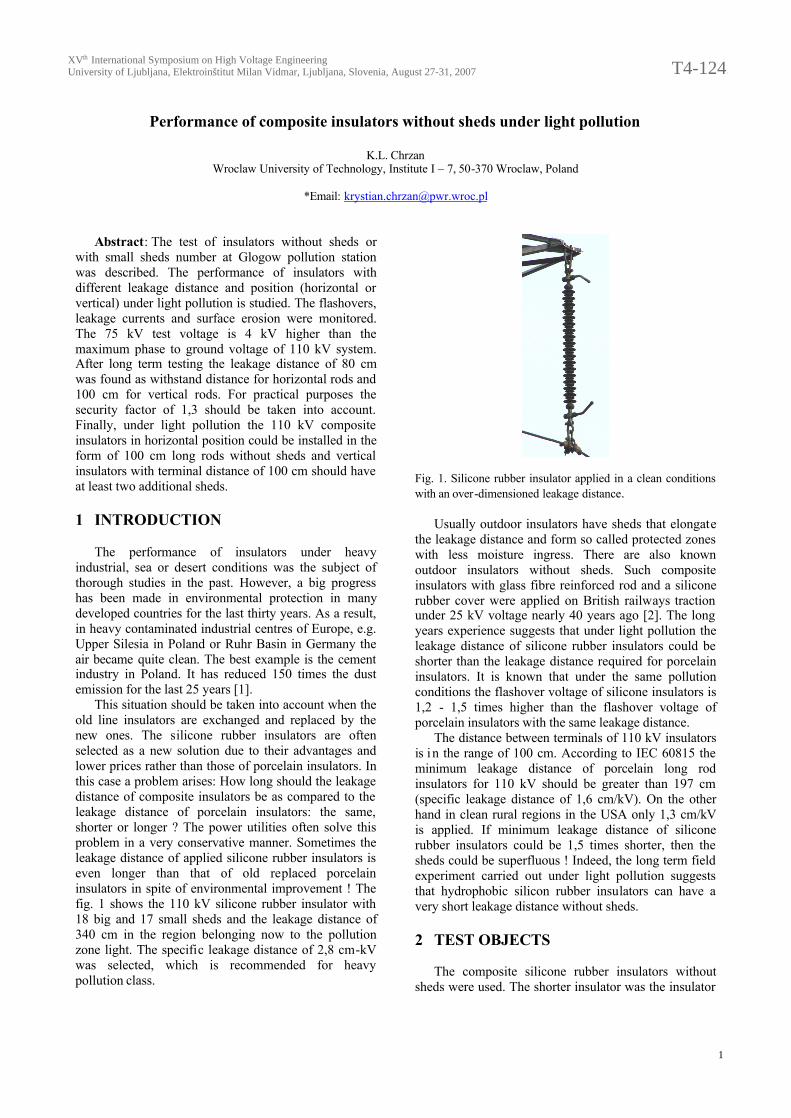
This situation should be taken into account when the old line insulators are exchanged and replaced by the new ones. The silicone rubber insulators are often selected as a new solution due to their advantages and lower prices rather than those of porcelain insulators. In this case a problem arises: How long should the leakage distance of composite insulators be as compared to the leakage distance of porcelain insulators: the same, shorter or longer ? The power utilities often solve this problem in a very conservative manner. Sometimes the leakage distance of applied silicone rubber insulators is even longer than that of old replaced porcelain insulators in spite of environmental improvement ! The fig. 1 shows the 110 kV silicone rubber insulator with 18 big and 17 small sheds and the leakage distance of 340 cm in the region belonging now to the pollution zone light. The specific leakage distance of 2,8 cm-kV was selected, which is recommended for heavy pollution class.
Fig. 1. Silicone rubber insulator applied in a clean conditions with an over-dimensioned leakage distance.
Usually outdoor insulators have sheds that elongate
the leakage distance and form so called protected zones with less moisture ingress. There are also known outdoor insulators without sheds. Such composite insulators with glass fibre reinforced rod and a silicone rubber cover were applied on British railways traction under 25 kV voltage nearly 40 years ago [2]. The long years experience suggests that under light pollution the leakage distance of silicone rubber insulators could be shorter than the leakage distance required for porcelain insulators. It is known that under the same pollution conditions the flashover voltage of silicone insulators is 1,2 - 1,5 times higher than the flashover voltage of porcelain insulators with the same leakage distance.
The distance between terminals of 110 kV insulators is in the range of 100 cm. According to IEC 60815 the minimum leakage distance of porcelain long rod insulators for 110 kV should be greater than 197 cm (specific leakage distance of 1,6 cm/kV). On the other hand in clean rural regions in the USA only 1,3 cm/kV is applied. If minimum leakage distance of silicone rubber insulators could be 1,5 times shorter, then the sheds could be superfluous ! Indeed, the long term field experiment carried out under light pollution suggests that hydrophobic silicon rubber insulators can have a very short leakage distance without sheds.
2 TEST OBJECTS
The composite silicone rubber insulators without sheds were used. The shorter insulator was the insulator
XV International Symposium on High Voltage Engineeringth
University of Ljubljana, Elektroinštitut Milan Vidmar, Ljubljana, Slovenia, August 27-31, 2007 T4-124.pdf
1
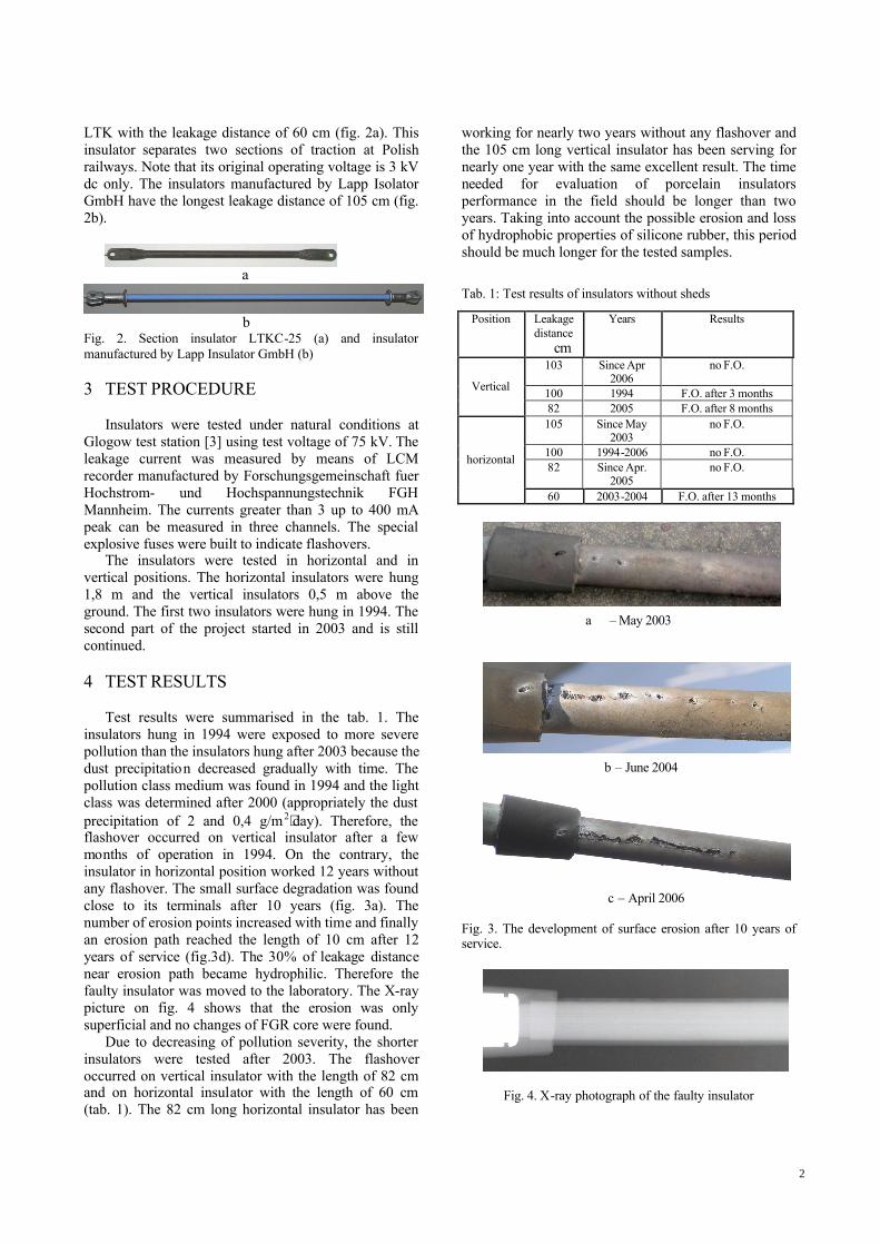
LTK with the leakage distance of 60 cm (fig. 2a). This insulator separates two sections of traction at Polish railways. Note that its original operating voltage is 3 kV dc only. The insulators manufactured by Lapp Isolator GmbH have the longest leakage distance of 105 cm (fig. 2b).
a
b Fig. 2. Section insulator LTKC-25 (a) and insulator manufactured by Lapp Insulator GmbH (b)
3 TEST PROCEDURE
Insulators were tested under natural conditions at
Glogow test station [3] using test voltage of 75 kV. The leakage current was measured by means of LCM recorder manufactured by Forschungsgemeinschaft fuer Hochstrom- und Hochspannungstechnik FGH Mannheim. The currents greater than 3 up to 400 mA peak can be measured in three channels. The special explosive fuses were built to indicate flashovers.
The insulators were tested in horizontal and in vertical positions. The horizontal insulators were hung 1,8 m and the vertical insulators 0,5 m above the ground. The first two insulators were hung in 1994. The second part of the project started in 2003 and is still continued.
4 TEST RESULTS
Test results were summarised in the tab. 1. The
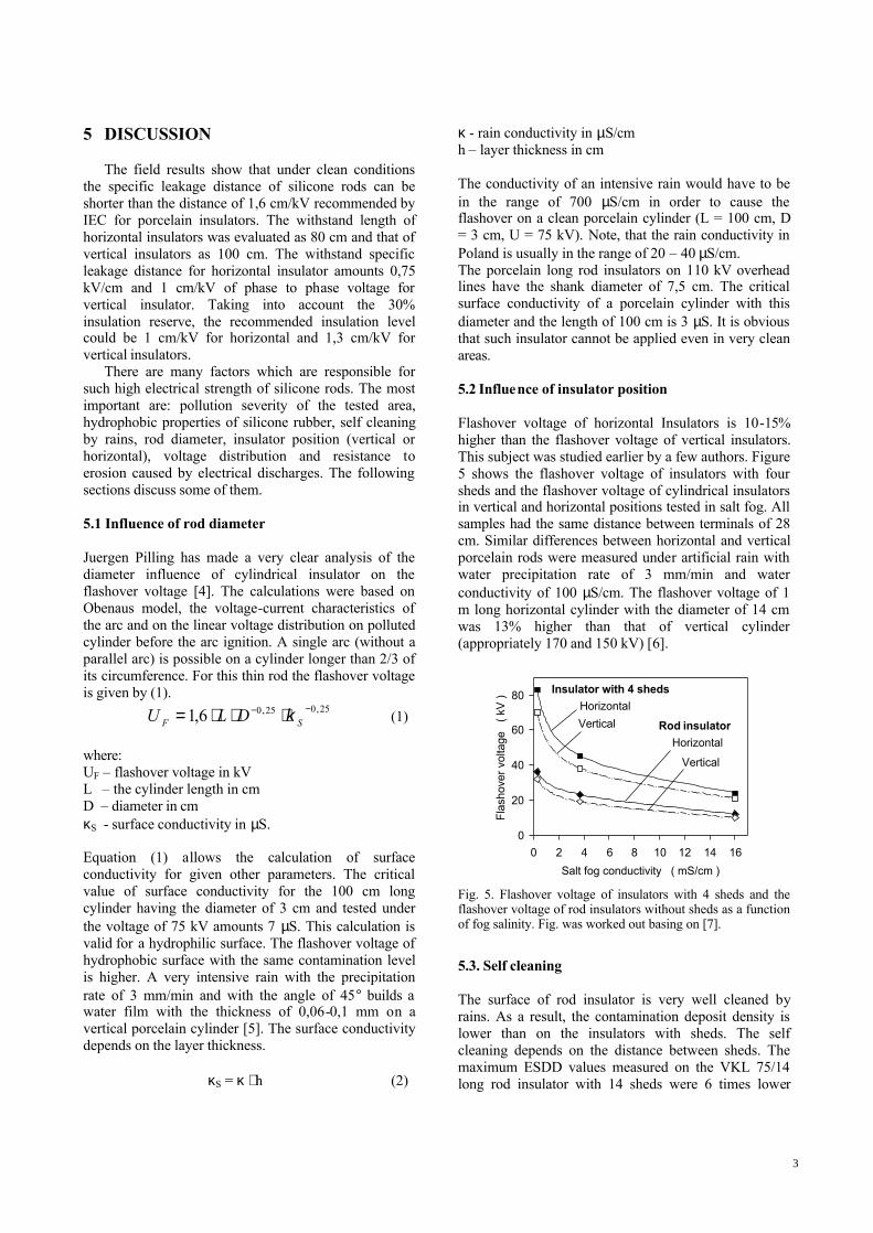
insulators hung in 1994 were exposed to more severe pollution than the insulators hung after 2003 because the dust precipitation decreased gradually with time. The pollution class medium was found in 1994 and the light class was determined after 2000 (appropriately the dust precipitation of 2 and 0,4 g/m2⋅day). Therefore, the flashover occurred on vertical insulator after a few months of operation in 1994. On the contrary, the insulator in horizontal position worked 12 years without any flashover. The small surface degradation was found close to its terminals after 10 years (fig. 3a). The number of erosion points increased with time and finally an erosion path reached the length of 10 cm after 12 years of service (fig.3d). The 30% of leakage distance near erosion path became hydrophilic. Therefore the faulty insulator was moved to the laboratory. The X-ray picture on fig. 4 shows that the erosion was only superficial and no changes of FGR core were found.
Due to decreasing of pollution severity, the shorter insulators were tested after 2003. The flashover occurred on vertical insulator with the length of 82 cm and on horizontal insulator with the length of 60 cm (tab. 1). The 82 cm long horizontal insulator has been
working for nearly two years without any flashover and the 105 cm long vertical insulator has been serving for nearly one year with the same excellent result. The time needed for evaluation of porcelain insulators performance in the field should be longer than two years. Taking into account the possible erosion and loss of hydrophobic properties of silicone rubber, this period should be much longer for the tested samples.
Tab. 1: Test results of insulators without sheds
Position Leakage distance
cm
Years Results
103 Since Apr 2006
no F.O.
100 1994 F.O. after 3 months Vertical
82 2005 F.O. after 8 months 105 Since May
2003 no F.O.
100 1994-2006 no F.O. 82 Since Apr.
2005 no F.O. horizontal
60 2003-2004 F.O. after 13 months
a – May 2003
b – June 2004
c – April 2006
Fig. 3. The development of surface erosion after 10 years of service.
Fig. 4. X-ray photograph of the faulty insulator
2
5 DISCUSSION
The field results show that under clean conditions the specific leakage distance of silicone rods can be shorter than the distance of 1,6 cm/kV recommended by IEC for porcelain insulators. The withstand length of horizontal insulators was evaluated as 80 cm and that of vertical insulators as 100 cm. The withstand specific leakage distance for horizontal insulator amounts 0,75 kV/cm and 1 cm/kV of phase to phase voltage for vertical insulator. Taking into account the 30% insulation reserve, the recommended insulation level could be 1 cm/kV for horizontal and 1,3 cm/kV for vertical insulators.
There are many factors which are responsible for such high electrical strength of silicone rods. The most important are: pollution severity of the tested area, hydrophobic properties of silicone rubber, self cleaning by rains, rod diameter, insulator position (vertical or horizontal), voltage distribution and resistance to erosion caused by electrical discharges. The following sections discuss some of them. 5.1 Influence of rod diameter Juergen Pilling has made a very clear analysis of the diameter influence of cylindrical insulator on the flashover voltage [4]. The calculations were based on Obenaus model, the voltage-current characteristics of the arc and on the linear voltage distribution on polluted cylinder before the arc ignition. A single arc (without a parallel arc) is possible on a cylinder longer than 2/3 of its circumference. For this thin rod the flashover voltage is given by (1).
25,025,06,1 −− ⋅⋅⋅= SF DLU κ (1) where: UF – flashover voltage in kV L – the cylinder length in cm D – diameter in cm κS - surface conductivity in µS. Equation (1) allows the calculation of surface conductivity for given other parameters. The critical value of surface conductivity for the 100 cm long cylinder having the diameter of 3 cm and tested under the voltage of 75 kV amounts 7 µS. This calculation is valid for a hydrophilic surface. The flashover voltage of hydrophobic surface with the same contamination level is higher. A very intensive rain with the precipitation rate of 3 mm/min and with the angle of 45° builds a water film with the thickness of 0,06-0,1 mm on a vertical porcelain cylinder [5]. The surface conductivity depends on the layer thickness. κS = κ ⋅ h (2)
κ - rain conductivity in µS/cm h – layer thickness in cm The conductivity of an intensive rain would have to be in the range of 700 µS/cm in order to cause the flashover on a clean porcelain cylinder (L = 100 cm, D = 3 cm, U = 75 kV). Note, that the rain conductivity in Poland is usually in the range of 20 – 40 µS/cm. The porcelain long rod insulators on 110 kV overhead lines have the shank diameter of 7,5 cm. The critical surface conductivity of a porcelain cylinder with this diameter and the length of 100 cm is 3 µS. It is obvious that such insulator cannot be applied even in very clean areas. 5.2 Influence of insulator position Flashover voltage of horizontal Insulators is 10-15% higher than the flashover voltage of vertical insulators. This subject was studied earlier by a few authors. Figure 5 shows the flashover voltage of insulators with four sheds and the flashover voltage of cylindrical insulators in vertical and horizontal positions tested in salt fog. All samples had the same distance between terminals of 28 cm. Similar differences between horizontal and vertical porcelain rods were measured under artificial rain with water precipitation rate of 3 mm/min and water conductivity of 100 µS/cm. The flashover voltage of 1 m long horizontal cylinder with the diameter of 14 cm was 13% higher than that of vertical cylinder (appropriately 170 and 150 kV) [6].
Salt fog conductivity ( mS/cm )0 2 4 6 8 10 12 14 16
Flas
hove
r vol
tage
( k
V )
0
20
40
60
80 Insulator with 4 shedsHorizontalVertical Rod insulator
Horizontal
Vertical
Fig. 5. Flashover voltage of insulators with 4 sheds and the flashover voltage of rod insulators without sheds as a function of fog salinity. Fig. was worked out basing on [7].
5.3. Self cleaning The surface of rod insulator is very well cleaned by rains. As a result, the contamination deposit density is lower than on the insulators with sheds. The self cleaning depends on the distance between sheds. The maximum ESDD values measured on the VKL 75/14 long rod insulator with 14 sheds were 6 times lower
3

than the maximum ESDD on SWZP4 post insulator with 20 sheds. The DDD ratio of 9 for both insulators was found [8].The contamination deposit density on the rod insulator is therefore at least 10 times lower than on insulators with 20 sheds. 6 CONCLUSIONS
The electrical strength of cylindrical porcelain insulators in horizontal position is 10 – 15% higher than that of porcelain insulators in vertical position. A bit higher difference of 20 – 25% was found for horizontal or vertical silicone rubber rods in field under light pollution conditions.
The withstand specific leakage distance of silicone rubber rods under light pollution is very short and amounts 0,75 cm/kV for horizontal position and 1 cm for vertical position. Taking into account the 30% insulation reserve, the recommended insulation level could be 1 cm/kV for horizontal and 1,3 cm/kV for vertical insulators.
The 110 kV silicone rubber insulators with the basic impulse level BIL of 500 kV (the distance between terminals about 100 cm) with 2 – 3 sheds can be used in light pollution conditions.
6 ACKNOWLEDGMENT
The field test was carried out at Glogow Pollution Test Station. Author thanks the Advisory Board of Glogow Copper Smelting Plant, especially Mr. Andrzej Szydlo and Mr. Jacek Rzepecki for their help in test station maintenance.
7 REFERENCES
[1] K.L. Chrzan, S. Abdi, A. Mekhaldi, Impact of environmental conditions in West Europe, Poland and Algeria on outdoor insulators performance and selection. Int. Symp. On High Voltage Engineering, Lubljana 2007
[2] A.G. Goldring, P.R. Hartshorn, C. Ricketts, W. Robinson, Insulation for highßvoltage ac railwaz electrification in Great Britain, Proc. IEE, vol. 116, August 1969, pp. 1377ß1386
[3] K.L. Chrzan, A. Haddad, Behaviour of insulators and surge arrestersat Glogow pollution test station. 39 th Universities Power Engineering Conference UPEC, Bristol 2004. pp. 193-196, Available: http://ieeexplore.ieee.org/iel5/9986/32065/01491990.pdf
[4] J. Pilling, L. Berndt, M. Khatib, T. Seelig, Der Fremdschichtueberschlag von Isolatoren mit gleichmaessigen Verschmutzung bei Wechselspannung. Wissenschaftliche Berichte der TH Zittau 1235 (1990), pp. 38-41
[5] H. Streubel, Die Berechnung der Regen-Ueberschlag-wechselspannung. Hermsdorfer Technische Mitteilungen, Heft 31, 1971, pp. 974-980
[6] H. Streubel, Zur Entwicklung des Ueberschlages beregneter Isolatoren bei Wechselspannung. Hermsdorfer Technischer Mitteilungen, Heft 22, 1968, pp. 691-695
[7] K.N. Mathes, Performance of simple insulator shapes under heavily contaminated conditions. IEEE Trans. on Electrical Insulation, vol. 7, June 1972, pp. 64-78
[8] K.L. Chrzan, Pollution test station Glogow, twenty years of research, Int. Symposium on High Voltage Engineering, Delft 2003, pp. 2003
4