xs series astm communication specifications - medteh.info · status to neutral status. the sender...
TRANSCRIPT

XS Series ASTM Communication Specifications
Revision 2.5
Revised on December 21, 2012

XS Series ASTM Communication Specifications_Revision 2.5 2/39
Revision History Revision Date Major Contents of Changes 2.2 January 18, 2006 Initial Release Version 2.4 March 22, 2007 Correction of mistake in statement of settable baud rate types
Correction of mistake in communication example Correction of range of QC file number set for requested record from
the mistaken “1 - 40” to the correct “1 - 20” Correction of mistake in description of QC test body number for
requested record Compatibility with ASTM E1381-02 IP message reverted from “Abn_Lympho?” to
“Abn_Lympho/Blasts?” only for North American specification products
Correction of mistake in comment record send/receive example 2.5 April 25, 2012 Output of “PRBC?” added to IP messages (Suspect)

XS Series ASTM Communication Specifications_Revision 2.5 3/39
Table of Contents
1. Scope-----------------------------------------------------------------------------------------------------------------------------4
2. Terminology -------------------------------------------------------------------------------------------------------------------4
3. Communication Specifications-------------------------------------------------------------------------------------------5
3.1 Physical Layer (Hardware)-------------------------------------------------------------------------------------- 6
3.1.1 Connectors ------------------------------------------------------------------------------------------------------- 6
3.1.2 Signal identification level ------------------------------------------------------------------------------------- 6
3.1.3 Connection cable------------------------------------------------------------------------------------------------ 6
3.1.4 Interface parameters------------------------------------------------------------------------------------------- 7
3.1.5 Standard specifications (ASTM E1381-02)---------------------------------------------------------------- 7
3.2 Data Link Layer (Transmission Protocol) ------------------------------------------------------------------ 7
3.2.1. Communication Status ---------------------------------------------------------------------------------------- 7
3.2.2. Establishment Phase ------------------------------------------------------------------------------------------- 8
3.2.3. Transfer Phase -------------------------------------------------------------------------------------------------- 8
3.2.4. Termination Phase -------------------------------------------------------------------------------------------- 10
3.2.5. Timeout ---------------------------------------------------------------------------------------------------------- 10
3.3 Presentation Layer -----------------------------------------------------------------------------------------------11
3.3.1 Messages, Records and Fields------------------------------------------------------------------------------- 11
3.3.2 Communication Protocol------------------------------------------------------------------------------------- 13
3.3.3 Details of Record----------------------------------------------------------------------------------------------- 15
4. Examples of Communication ------------------------------------------------------------------------------------------- 34
4.1. Inquiry of Analysis Order (IPU Host Computer) ----------------------------------------------------34
4.1.1. When making a Batch Inquiry from the work list: ----------------------------------------------------- 34
4.1.2. When making a Real-Time Inquiry in the manual mode analysis:---------------------------------- 34
4.1.3. When making a Real-Time Inquiry in the sampler mode analysis: --------------------------------- 34
4.2. Analysis Information (Host Computer IPU)----------------------------------------------------------35
4.2.1. When an Analysis Order exists: ---------------------------------------------------------------------------- 35
4.2.2. When no Analysis Order exists: ---------------------------------------------------------------------------- 35
4.3. Analysis Results and QC Results (IPU Host Computer)------------------------------------------36
4.3.1. Transmitting Analysis Results: ----------------------------------------------------------------------------- 36
4.3.2. Transmitting QC Result in real-time mode: ------------------------------------------------------------- 37
4.3.3. Transmitting QC Result in a manual batch mode: ----------------------------------------------------- 38
Appendix A. TCP/IP Communication ----------------------------------------------------------------------------------- 39
A.1 Network Interface Layer---------------------------------------------------------------------------------------39
A.2 TCP/IP---------------------------------------------------------------------------------------------------------------39
A.3 Transmission Timing -------------------------------------------------------------------------------------------39
A.4 Transmission Messages ----------------------------------------------------------------------------------------39
(Example) Real-Time Inquiry:-------------------------------------------------------------------------------------------- 39

XS Series ASTM Communication Specifications_Revision 2.5 4/39
1. Scope This document describes the Data Communication Specifications for XS-1000i and XS-800i (hereinafter, describes XS-Series) using ASTM E1394-97, E1381-02.
[Note] ASTM (America Society for Testing and Materials), one of the world largest volunteer non-profit organizations, founded in 1898 for the purpose of creating standard regulations for materials, products and system services. This specification conforms to the following two standards:
ASTM E1381-02: Specifications for low-level protocols to transfer data between clinical laboratory instruments and computer systems.
ASTM E1394-97: Standard specifications for transferring data between clinical instruments and computer systems.
2. Terminology The definition of the terminology used in this document is described in the following.
1) Numerics:
Indicates ASCII codes “0” (30H) through “9” (39H). 2) Alphabet:
Indicates ASCII codes “A” (41H) through “Z” (5AH) and “a” (61H) through “z” (7AH). 3) Alpha-numeric:
Indicates numerical or alphabetical character.

XS Series ASTM Communication Specifications_Revision 2.5 5/39
3. Communication Specifications
Communication specifications are based on a layer protocol. 1. Physical layer
Specifies the sending and receiving of signals between the IPU and the host computer through physical and electrical connections. See the subsequent section, “3.1 Physical Layer (Hardware)”.
2. Data link layer
Specifies the sending and receiving of data by link connections and for each frame between the IPU and the host computer. See the subsequent section, “3.2 Data Link Layer (Transmission Protocol)”.
3. Presentation layer
Specifies the messages that are sent and received by the IPU and the host computer. See the subsequent section, “3.3 Presentation Layer”. Presentation layer Specifies message specifications. Data link layer Specifies link connection and frame specifications. Physical layer Specifies mechanical and electrical specifications.
Caution: The IPU of the XS series supports serial connection and TCP/IP. For serial connection, it conforms to ASTM E1381-02/ASTM E1394-97. For TCP/IP connection, the following two modes are supported as output modes for data formatted according to ASTM 1394-97. 1. ASTM E1381-02 mode Presentation layer conforms to ASTM E1394-97. Data link layer conforms to ASTM E1381-02. Physical layer conforms to IEEE802.3. 2. ASTM E1381-95 mode Presentation layer conforms to ASTM E1394-97. Data link layer conforms to IEEE802.3.
TCP/IP connection
Serial connection ASTM E1381-95 mode *1 ASTM E1381-02 mode *1
Presentation layer ASTM E1394-97 ASTM E1394-97 ASTM E1394-97 Data link layer *2 ASTM E1381-02 IEEE802.3 ASTM E1381-02 Physical layer *2 ASTM E1381-02 IEEE802.3 IEEE802.3
*1: For TCP/IP connections, if the “Format” setting parameter on the IPU host computer is set to “ASTM 1381-02/1394-97”, operation should be performed in ASTM E1381-02 mode. ; if the parameter is set to “ASTM 1381-95/1394-97”, operation should be performed in ASTM E1381-95 mode. *2: IEEE802.3 specifications for the data link layer and physical layer are not stated in this document.

XS Series ASTM Communication Specifications_Revision 2.5 6/39
3.1 Physical Layer (Hardware) 3.1.1 Connectors Although the ASTM standard specifies a DB-25-pin connector for the computer as standard, a DB-9-pin male connector, which is located on the rear of the instrument, is used to communicate.
Table 1: Connector pin assignment Pin No. Signal name Signal direction Remarks
1 NC Not used 2 Receive data RxD To XS from host 3 Transmit data TxD From XS to host 4 Data terminal ready DTR From XS to host Not used in the ASTM 5 Signal ground SG - 6 Data set ready DSR To XS from host Not used in the ASTM 7 Request to send RTS From XS to host Not used in the ASTM 8 Clear to send CTS To XS from host Not used in the ASTM 9 NC Not Used
[Note] The control signals are not used with ASTM specifications. Do not connect unused pins since a permanent damage to the hardware will result.
3.1.2 Signal identification level
Table 2: Signal identification level
Level Data signal Control signal +3V or more Logic “0”, start bit ON -3V or less Logic “1”, stop bit OFF
[Note 1] The ASTM communication will not use these control signals.
3.1.3 Connection cable The IPU uses a cable with a DB-9-pin female connector, in accordance with the following connection chart.
IPUDB-9
TxD
RxD
SG
RTS
CTS
DTR
DSR
NCNC
3
2
5
7
8
4
6
19
Host computerDB-9
3
2
5
7
8
4
6
DB-25
2
3
7
4
5
20
6
TxD
RxD
SG
RTS
CTS
DTR
DSR
XS Series ASTM Communication Specifications_Revision 2.5 7/39
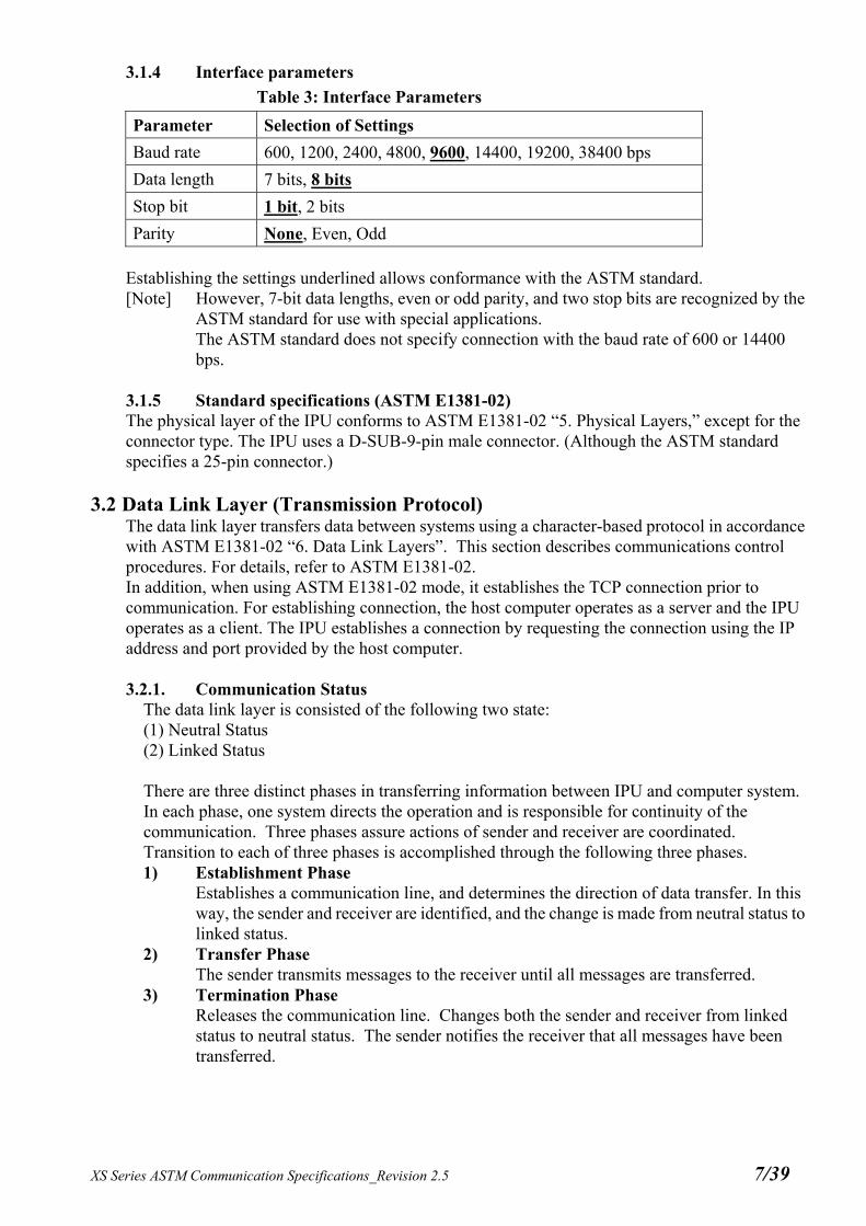
3.1.4 Interface parameters
Table 3: Interface Parameters
Parameter Selection of Settings
Baud rate 600, 1200, 2400, 4800, 9600, 14400, 19200, 38400 bps
Data length 7 bits, 8 bits
Stop bit 1 bit, 2 bits
Parity None, Even, Odd Establishing the settings underlined allows conformance with the ASTM standard. [Note] However, 7-bit data lengths, even or odd parity, and two stop bits are recognized by the
ASTM standard for use with special applications. The ASTM standard does not specify connection with the baud rate of 600 or 14400 bps.
3.1.5 Standard specifications (ASTM E1381-02) The physical layer of the IPU conforms to ASTM E1381-02 “5. Physical Layers,” except for the connector type. The IPU uses a D-SUB-9-pin male connector. (Although the ASTM standard specifies a 25-pin connector.)
3.2 Data Link Layer (Transmission Protocol) The data link layer transfers data between systems using a character-based protocol in accordance with ASTM E1381-02 “6. Data Link Layers”. This section describes communications control procedures. For details, refer to ASTM E1381-02. In addition, when using ASTM E1381-02 mode, it establishes the TCP connection prior to communication. For establishing connection, the host computer operates as a server and the IPU operates as a client. The IPU establishes a connection by requesting the connection using the IP address and port provided by the host computer.
3.2.1. Communication Status
The data link layer is consisted of the following two state: (1) Neutral Status (2) Linked Status There are three distinct phases in transferring information between IPU and computer system. In each phase, one system directs the operation and is responsible for continuity of the communication. Three phases assure actions of sender and receiver are coordinated. Transition to each of three phases is accomplished through the following three phases. 1) Establishment Phase
Establishes a communication line, and determines the direction of data transfer. In this way, the sender and receiver are identified, and the change is made from neutral status to linked status.
2) Transfer Phase The sender transmits messages to the receiver until all messages are transferred.
3) Termination Phase Releases the communication line. Changes both the sender and receiver from linked status to neutral status. The sender notifies the receiver that all messages have been transferred.

XS Series ASTM Communication Specifications_Revision 2.5 8/39
3.2.2. Establishment Phase 1) The sender (IPU) sends an [ENQ] signal to the receiver (host computer). To respond to the
sender, the receiver performs the following action: - Returns an [ACK] signal when communications are enabled. - Returns a [NAK] when communications are disabled. The sender waits for at least 10 seconds before attempting to send an [ENQ] signal again.
2) When both sender and receiver send [ENQ] signals, the host computer must yield control authority to the IPU. - The IPU sends [ENQ] again after 1 second. - The host computer must wait for 20 seconds before sending [ENQ] again.
3.2.3. Transfer Phase During the transfer phase, the sender sends messages to the receiver. The transfer phase continues until all messages have been sent. 1) Messages are sent in multiple frames. Each frame contains a maximum of 64,000
characters* (including frame overhead). If the message is longer than 63,993 characters, it is divided into two or more frames. * When using a serial connection, in order to maintain compatibility with E1381-95, the
maximum number of characters in a record is set to 240 characters. For complete compatibility with E1381-02, it is necessary to set the maximum number of characters in a record to 63,993 characters. For information on the setting method, contact your nearest branch office, sales office, or representative. When using TCP/IP connection, the maximum number of characters is set to 63,993 characters.

XS Series ASTM Communication Specifications_Revision 2.5 9/39
2) Multiple messages cannot be included in a single frame. 3) When the record is within the maximum number of characters, a text frame with the
following format is sent. [STX] [F#] [Text] [ETX] [CHK1] [CHK2] [CR] [LF] If the text is longer than the maximum number of characters, it is divided into 2 or more frames. The intermediate frame text termination code is [ETB], and the final frame text termination code is [ETX], as shown below. [STX] [F#] [Text] [ETB] [CHK1] [CHK2] [CR] [LF] [STX] [F#] [Text] [ETB] [CHK1] [CHK2] [CR] [LF] ... [STX] [F#] [Text] [ETX] [CHK1] [CHK2] [CR] [LF] where:
Code Explanation [STX] Start of a frame [F#] Frame number. One of the numbers 0 to 7 is used, starting with 1 and repeating 2,
3, 4, 5, 6, 7, 0. In case of retransmission, the same frame number is sent. [Text] ASTM E1394-97 records are used. (See the subsequent section, Presentation
layer.) For this reason the codes below will not be used. 0x00 - 0x06, 0x08, 0x0A, 0x0E - 0x1F, 0x7F, 0xFF
[ETB] Control code indicating end of text (for intermediate frame) [ETX] Control code indicating end of text (for final frame) [CHK1], [CHK2]
Expressed by characters “0” - “9” and “A” - “F”. Characters beginning from the character after [STX] and until [ETB] or [ETX] (including [ETB] or [ETX]) are added in binary. The 2-digit numbers, which represent the least significant 8 bits in hexadecimal code, are converted to ASCII characters “0” - “9” and “A” - “F”. The most significant digit is stored in CHK1 and the least significant digit in CHK2.
[CR] [LF] Control codes indicating end of frame
4) If the receiver has successfully received the frame, and is prepared to receive the next frame, receiver responds with [ACK]. After the sender receives [ACK], sender advances the frame number and sends either a new frame or transitions to the termination phase.
5) If the receiver fails to receive the frame and is prepared to receive the same frame again, receiver responds with [NAK]. After sender receives [NAK], sender sends the most recent frame again, using the same frame number. If a total of 6 attempts to send the frame failed, sender transitions to the termination phase and must end sending of the message.

XS Series ASTM Communication Specifications_Revision 2.5 10/39
6) The IPU processes the response of [EOT] from the host computer as [ACK]. (Response of [EOT] from the receiver is usually a request of transmission to the sender. However, IPU does not support this.)
3.2.4. Termination Phase During the termination phase, the status returns to neutral. The sender sends the [EOT] to inform the receiver that the message transmission has been completed. When the sender sends [EOT], sender transitions to neutral status. When the receiver receives [EOT], receiver transitions to neutral status.
3.2.5. Timeout The timer is used to detect a failure to coordinate between the sender and receiver. The timer is used as a mean of recovery for communication line and communication destination device failures. 1) During the establishment phase, the timer is set when the sender sends [ENQ]. Time out
results if a response of [ACK], [NAK], or [ENQ] is not received within 15seconds. After time out, the sender transitions to the termination phase.
2) During the transfer phase, the timer is sets when the sender sends the final character of a
frame. Time out results if no response is received within 15 seconds. After time out, the sender transitions to the termination phase. The receiver sets a 30-second timer when first entering the transfer phase or when responding (either [ACK] or [NAK] ) to a frame. Time out results if the receiver does not receive a frame or [EOT] from the sender within 30 seconds. After time out, the receiver discards the latest incomplete message and transitions to the termination phase.

XS Series ASTM Communication Specifications_Revision 2.5 11/39
3.3 Presentation Layer
3.3.1 Messages, Records and Fields
3.3.1.1. Messages In the presentation layer, all data is transmitted using messages. Messages are composed of record arrays that start with the message header record (H) and end with message termination record (L).
3.3.1.2. Records A record is a series of text, beginning with an ASCII alphabet character referred to as the identifier, and ending with [CR] complete message. Records are end by record delimiter.
Table 4: Records
Record Type Record
Identifier Level Contents
Header Record
H
0
Contains the sender and receiver information
Patient Information Record P 1 Contains the patient information
Inquiry Record
Q
1
Contains test order inquiry information requesting to the host computer
Test Order Record O 2 Contains the test order information
Test Result Record R 3 Contains analysis result information
Comment Record
C
1-4
Contains the specimen comment and patient comment information
Manufacturer Information Record M 1-4 Not used
Scientific Information Record S N/A Not used
Message Terminator Record L 0 Indicates the end of the message
A smaller level number indicates a higher level. A higher-level record contains information that is common to all lower-level records. All levels other than 0 must be located after higher levels. However, the manufacturer information record (not used) and the comment record can be inserted at any level. They are considered to be one level lower than the preceding record. Example of transmission H->P->O->R->L ....... Correct H->R->L ................... Incorrect, because P and O must be transmitted in prior to R.
XS Series ASTM Communication Specifications_Revision 2.5 12/39
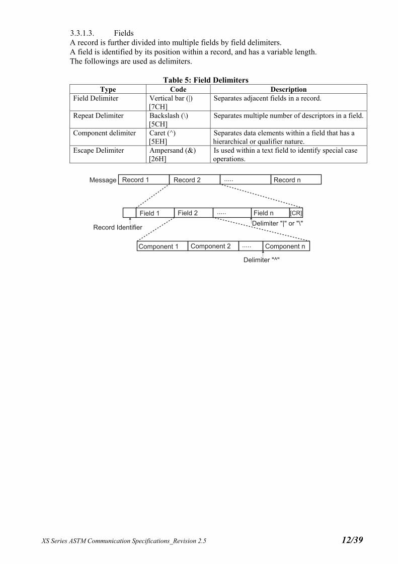
3.3.1.3. Fields A record is further divided into multiple fields by field delimiters. A field is identified by its position within a record, and has a variable length. The followings are used as delimiters.
Table 5: Field Delimiters Type Code Description
Field Delimiter Vertical bar (|) [7CH]
Separates adjacent fields in a record.
Repeat Delimiter Backslash (\) [5CH]
Separates multiple number of descriptors in a field.
Component delimiter Caret (^) [5EH]
Separates data elements within a field that has a hierarchical or qualifier nature.
Escape Delimiter Ampersand (&) [26H]
Is used within a text field to identify special case operations.

XS Series ASTM Communication Specifications_Revision 2.5 13/39
3.3.2 Communication Protocol
3.3.2.1. Analysis Order Inquiry (IPU Host computer)
This protocol is used for XS-Series to inquire to the host computer an analysis order information to obtain the sample information. Inquiry can be made with keyword of either the sample ID No. or the combination of Rack No. and Tube Position No.
Table 6: Analysis Order Inquiry IPU Direction Host Computer ENQ ACK H (Header Record) ACK Q (Request Record) ACK L (Message Terminator Record) ACK EOT
Note: When using the ASTM E1381-95 mode of TCP/IP, handling of ENQ, ACK, and EOT is not performed. See Appendix A.
3.3.2.2. Analysis Information (Host computer IPU)
This protocol is used for the host computer to respond an analysis information against the inquiry made by the IPU. Comment record may be omitted.
Table 7: Analysis Information IPU Direction Host Computer ENQ ACK H (Header Record) ACK P (Patient Record) ACK C (Patient Comment Record) ACK O (Test Order Record) ACK C (Specimen Comment Record) ACK L (Message Terminator Record) ACK EOT
Note: When using the ASTM E1381-95 mode of TCP/IP, handling of ENQ, ACK, and EOT is not performed. See Appendix A.

XS Series ASTM Communication Specifications_Revision 2.5 14/39
3.3.2.3. Analysis Results & QC Data (IPU Host computer)
This protocol is used for the IPU to transmit the analysis results, the QC data in a real-time mode (QC sample No. is QC-xxxxxx and transmitted as similar to the regular sample data), and the QC data in a manual batch mode (selected QC data is output in the QC Chart screen). When the QC data is to be output, the patient record contains nothing, thus an empty patient record is transmitted. Comment record may be omitted.
Table 8: Analysis Results and QC Data IPU Direction Host Computer ENQ ACK H (Header Record) ACK P (Patient Record) ACK C (Patient Comment Record) ACK O (Test Order Record) ACK C (Specimen Comment Record) ACK
R (Result Record) ACK L (Message Terminator Record) ACK EOT
Note: When using the ASTM E1381-95 mode of TCP/IP, handling of ENQ, ACK, and EOT is not performed. See Appendix A.
Repeating the No. of parameters

XS Series ASTM Communication Specifications_Revision 2.5 15/39
3.3.3 Details of Record 3.3.3.1. Header Record
[Example of transmission] IPU Host computer
H|\^&|||XS^00-05^11001^^^^12345678||||||||E1394-97[CR] Host computer IPU
H|\^&|||||||||||E1394-97[CR]
Table 9: Details of Header Record ASTM Field
Field Name IPU Host Host IPU Max. Size (Bytes)
Remarks
7.1.1 Record type H H 1 Fixed 7.1.2 Delimiter definition | \^& | \^& 4 Fixed 7.1.3 Message control ID Not used Not used - 7.1.4 Access password Not used Not used - 7.1.5 Sender name or ID Analyzer name^
Software version^ Analyzer serial No.^^^^
PS code
Not used 8^ 13^
5^^^^ 8
7.1.6 Sender street address
Not used Not used -
7.1.7 Reserved field Not used Not used - 7.1.8 Sender Telephone
No. Not used Not used -
7.1.9 Sender characteristics
Not used Not used -
7.1.10 Receiver ID Not used Not used - 7.1.11 Comment Not used Not used - 7.1.12 Processing ID Not used Not used - 7.1.13 ASTM Version No. E1394-97 E1394-97 8 Fixed 7.1.14 Date and Time of
message Not used Not used -
Detailed Explanation of the fields:
1) 7.1.2 Delimiter definition “| \^&” is used as a fixed character string. No field delimiter is required between 7.1.1 and 7.1.2.
2) 7.1.5 Sender name or ID
Analyzer name is fixed as “XS”, and software version is referred to the software version the XS-Series is working with.

XS Series ASTM Communication Specifications_Revision 2.5 16/39
3.3.3.2. Patient Information Record [Example of transmission] IPU Host computer
P|1|||123456|^Johnson^Thomas||20010820|M|||||^Dr. M||||||||||||^^^West[CR] Host computer IPU
P|1|||100|^Carol^Thomas||20010820|F|||||^Dr. N||||||||||||^^^East[CR]
Table 10: Details of Patient Information Record ASTM Field
Field Name IPUHost HostIPU Max. size (Bytes)
Remarks
8.1.1 Record type P P 1 Fixed 8.1.2 Sequence No. Sequence No. Sequence No. 4 Sequence No. of
records 8.1.3 Practice assigned
patient ID Not used Not used -
8.1.4 Laboratory assigned patient ID
Not used Not used -
8.1.5 Patient ID No. Patient ID Patient ID 16 8.1.6 Patient name ^First name
^Last name ^First name ^Last name
^20 ^20
8.1.7 Mother’s maiden name
Not used Not used -
8.1.8 Birth date YYYYMMDD YYYYMMDD 8 Ex) 20010802 for 2nd of August 2001
8.1.9 Patient sex M, F or U M, F or U 1 Male, Female, or Unknown
8.1.10 Patient race Not used Not used - 8.1.11 Patient address Not used Not used - 8.1.12 Reserved Not used Not used - 8.1.13 Patient telephone No. Not used Not used - 8.1.14 Attending physician
ID ^Physician name ^Physician name ^20
8.1.15 Special field 1 Not used Not used - 8.1.16 Special field 2 Not used Not used - 8.1.17 Patient height Not used Not used - 8.1.18 Patient weight Not used Not used - 8.1.19 Patient’s known or
suspected diagnosis Not used Not used -
8.1.20 Patient active medications
Not used Not used -
8.1.21 Patient diet Not used Not used - 8.1.22 Practice field 1 Not used Not used - 8.1.23 Practice field 2 Not used Not used - 8.1.24 Admission and
discharge dates Not used Not used -
8.1.25 Admission status Not used Not used - 8.1.26 Location ^^^Ward ^^^Ward ^^^20 8.1.27 DRG or AVG Not used Not used - 8.1.28 DRG or AVG 2 Not used Not used - 8.1.29 Patient religion Not used Not used - 8.1.30 Marital status Not used Not used - 8.1.31 Isolation status Not used Not used - 8.1.32 Language Not used Not used - 8.1.33 Hospital service Not used Not used - 8.1.34 Hospital institution Not used Not used - 8.1.35 Dosage category Not used Not used -

XS Series ASTM Communication Specifications_Revision 2.5 17/39
Detailed Explanation of the fields: 1) 8.1.2 Sequence No.
The sequence number starts with 1 and indicates the sequence position in which the record appeared in the message. This number is reset to 1 when a higher-level record appears in the message.
2) 8.1.5 Patient ID No.
The patient ID is a unique patient identification and may contain a maximum of 16 digits of alpha-numerics and a hyphen “-” (2D h).
3) 8.1.6 Patient Name
The first name and the last name may be 20 characters each with consisting of alpha-numerics.
4) 8.1.8 Birth date The birthrate is the date of birth of the patient, and the date format is fixed with “YYYYMMDD”. Here, YYYY indicates the year, MM the month, and DD the day.
5) 8.1.9 Patient Sex
The patient sex is indicated with M, F or U. Here, M indicates male, F female, and U unknown.
6) 8.1.14 Attending Physician ID The attending physician ID may be entered with a maximum of 20 characters of alpha-numerics.
7) 8.1.26 Location
The patient ward name may be entered a maximum of 20 characters of alpha-numerics.

XS Series ASTM Communication Specifications_Revision 2.5 18/39
3.3.3.3. Request Information Record [Example of transmission] IPU Host computer
Q|1| 1^1^^M||||20010905150959[CR] Host computer IPU
Not used
Table 11: Details of Request Information Record ASTM Field
Field Name IPUHost HostIPU Max. Size (Bytes)
Remarks
12.1.1 Record Type Q Not used 1 Fixed 12.1.2 Sequence No. Sequence No. Not used 4 Sequence No. of records12.1.3 Starting Range ID No. Rack No.^
Tube position^ Sample No.^ Sample No. attribute
Not used 6^ 2^
15^ 1
Sample No. attribute is one of followings: M: Manual entry A: Automatic assignment by analyzer B: Barcode reader input
12.1.4 Ending Range ID No.
Not used Not used -
12.1.5 Universal test ID Not used Not used - 12.1.6 Nature of request time
limit Not used Not used -
12.1.7 Beginning request results date and time
YYYYMMDDHHMMSS
Not used 14
12.1.8 Ending request results date and time
Not used Not used -
12.1.9 Requesting physician name
Not used Not used -
12.1.10 Requesting physician telephone No.
Not used Not used -
12.1.11 User field No. 1 Not used Not used - 12.1.12 User field No. 2 Not used Not used - 12.1.13 Requested
information status code
Not used Not used -
Detailed Explanation of the fields:
1) 12.1.2 Sequence No. The sequence number starts with 1 and indicates the sequence position in which the record appeared in the message. This number is reset to 1 when a higher-level record appears in the message.
2) 12.1.3 Starting Range ID No.
Rack No. Up to 6-digit number assigned to the rack. Tube Position No. The sample position number within a rack, and is one of the numbers 01 through
10. Sample ID number Consisted of 15-digit of alpha-numerics and hyphen “-” (2D h). When the
sample ID number is less than 15 digits, spaces are padded to the most significant digits.
Note 1: In the manual mode analysis and in the real-time inquiry, sample ID number is the keyword to
inquire, and both the rack number and the tube position number will not be sent. Note 2: In the batch inquiry using the work list, both the rack number and the tube position number is the
keyword to inquire, and the sample ID number will not be sent.

XS Series ASTM Communication Specifications_Revision 2.5 19/39
Sample No. attribute M Sample ID No. is manually entered. A Analyzer automatically assigned number and is started with “ERR”.
This is used when the ID Read Error occurred. B Barcode reader read number
3) 12.1.7 Beginning request result date and time
The date format is fixed with “YYYYMMDDHHMMSS”. Here, YYYY indicates the year, MM the month, DD the day, HH the hour in the 24-hour system (00-23), MM the minute (00-59), and SS the second (00-59).

XS Series ASTM Communication Specifications_Revision 2.5 20/39
3.3.3.4. Test Order Record [Example of transmission] IPU Host computer
O|1||^^123-4567-890123^B|^^^^WBC\^^^^RBC\···· ^^^^NEUT#|||||||N||||||||||||||F[CR] Host computer IPU
O|1|^^123-4567-890123^C||^^^^WBC\^^^^RBC\····^^^^NEUT#||20010807101000|||||N||||||||||||||Q[CR]
Table 12: Details of Test Order Record
ASTM Field
Field Name IPUHost HostIPU Max. Size
(Bytes)
Remarks
9.4.1 Record type O O 1 Fixed 9.4.2 Sequence No. Sequence No. Sequence No. 4 Sequence No. of records9.4.3 Specimen ID Not used Rack No.^
Tube Position^ Sample No.^ Sample No. attribute
6^ 2^
15^ 1
9.4.4 Instrument specimen ID
Rack No.^ Tube Position^Sample No.^ Sample No. attribute
Not used 6^ 2^
15^ 1
Sample No. attribute is one of the followings: M: Manual entry A: Automatic assignment by the analyzer B: Barcode reader C: Set by the host computer
9.4.5 Universal Test ID ^^^^Parameter ^^^^Parameter ^^^^6 Test Order of each analysis parameter
9.4.6 Priority Not used Not used - 9.4.7 Requested/order date
and time Not used YYYYMMDD
HHMMSS 14
9.4.8 Specimen collection date and time
Not used Not used -
9.4.9 Collection end time Not used Not used - 9.4.10 Collection volume Not used Not used - 9.4.11 Collector ID Not used Not used - 9.4.12 Action code N, Q N, Q 1 N: Normal sample
Q: QC material 9.4.13 Danger code Not used Not used - 9.4.14 Relevant clinical
information Not used Not used -
9.4.15 Date/time specimen received
Not used Not used -
9.4.16 Specimen descriptor Not used Not used - 9.4.17 Ordering physician Not used Not used - 9.4.18 Physician’s
telephone No. Not used Not used -
9.4.19 User field No. 1 Not used Not used - 9.4.20 User field No. 2 Not used Not used - 9.4.21 Laboratory field No.
1 Not used Not used -
9.4.22 Laboratory field No. 2
Not used Not used -
9.4.23 Date/time results reported or last
modified
Not used Not used -
9.4.24 Instrument charge to computer system
Not used Not used -

XS Series ASTM Communication Specifications_Revision 2.5 21/39
ASTM Field
Field Name IPUHost HostIPU Max. Size
(Bytes)
Remarks
9.4.25 Instrument section ID
Not used Not used -
9.4.26 Report type F Y, Q 1 F: Final results (Fixed) Y: No test order Q: Response to inquiry
9.4.27 Reserved field Not used Not used - 9.4.28 Location or ward of
specimen collected Not used Not used -
9.4.29 Nosocomial infection flag
Not used Not used -
9.4.30 Material service Not used Not used - 9.4.31 Material institution Not used Not used -
Detailed Explanation of the fields:
1) 9.4.2 Sequence No. The sequence number starts with 1 and indicates the sequence position in which the record appeared in the message. This number is reset to 1 when a higher-level record appears in the message.
2) 9.4.3 Specimen ID
Rack No. Up to 6-digit number assigned to the rack. Return the same number that was inquired.
Tube Position No. The sample position number within a rack, and is one of the numbers 01 through 10. Return the same number that was inquired.
Sample ID number Consisted of 15-digit of alpha-numerics and hyphen “-” (2D h). The sample ID number starting with “QC” is reserved for the quality control samples. When the sample ID number is less than 15 digits, spaces should be padded to the most significant digits.
Sample No. attribute M Sample ID No. is manually entered. A Automatically assigned number by the analyzer. This number is assigned by
the automatic-increment function, and is used to set the sample number that is started with “ERR”. This is used when the ID Read Error occurred.
B Barcode reader read number. This is used when the sample ID number was read by the ID bar code reader.
C Host computer assigned number. When an inquiry with the keyword of the rack number and the tube position number is received, the host computer assigns the sample No.
Note: In the real-time inquiry with the keyword of the sample number, please return the same sample
number and the sample number attribute that were inquired. In the real-time inquiry with the keywords of the rack number and the tube position number, or in
the batch inquiry from the work list, please return the appointed sample number specified by the rack number and the tube position number, and the sample number attribute “C”.
3) 9.4.4 Instrument Specimen ID Rack No. Rack number that was used to analyze, and is consisted with a 6-digit number.
Rack number will not be sent if analyzed in the manual mode. Tube Position No. The sample position number within a rack, and is one of the numbers 01 through
10. Return the same number that was inquired. Tube position number will not be sent if analyzed in the manual mode.
Sample ID number There are cases that the bar code read error number, QC sample number, or QC file number may be set in addition to the usual 15-digit sample ID No.
Usual sample No. Consisted of 15-digit alpha-numerics and hyphen “-” (2D h). When the sample ID number is less than 15 digits, spaces are padded to the most significant digits.

XS Series ASTM Communication Specifications_Revision 2.5 22/39
Bar code read error No. The most significant 3-digit is fixed with “ERR” and following 12 digits
in maximum with alpha-numerics and hyphen “-” (2D h). QC sample number Up to 11 digits of alpha-numeric and hyphen “-” (2D h) starting with
“QC-”. Spaces are padded to the most significant digits. This QC sample number is used when QC data is output in a real time transmission.
QC File No. Outputs the file No. “1” through “20” or “XbarM”, and is used to output the QC data manually.
Sample No. attribute M Sample ID No. was manually entered. A Automatically assigned number by the analyzer. This number is assigned by
the automatic-increment function, and is used to set the sample number that is started with “ERR”. This is used when the ID Read Error occurred.
B Barcode reader read number. This is used when the sample ID number was read by the ID bar code reader.
C Host computer assigned number. This is used when the sample ID number was assigned by the host computer.
[Note] The manual output of the QC data (QC Chart output) will not send the rack number, tube
position number and Sample number attribute.
4) 9.4.5 Universal Test ID When an order is sent from the host computer to the IPU, set the parameter that is to be ordered. When a multiple parameters are to be set, use a repeat delimiter (\). For example, ^^^^parameter1\^^^^parameter2\^^^^parameter3
Table 13: Abbreviation of Universal Test ID Abbreviated parameter name Parameter name WBC Number of all leucocytes RBC Number of all erythrocytes HGB Hemoglobin concentration HCT Hematocrit value: Erythrocytes ratio of total blood volume MCV Mean erythrocyte volume in total sample MCH Mean hemoglobin volume per RBC MCHC Mean hemoglobin concentration of erythrocytes PLT Number of all platelets NEUT% Neutrophil Percent LYMPH% Lymphocyte Percent MONO% Monocyte Percent EO% Eosinophil Percent BASO% Basophil Percent NEUT# Neutrophil Count LYMPH# Lymphocyte Count MONO# Monocyte Count EO# Eosinophil Count BASO# Basophil Count RDW-SD Calculated distribution width of erythrocytes, standard deviation RDW-CV Calculated distribution width of erythrocytes, coefficient of variationPDW *1 Calculated distribution width of platelets MPV Mean platelet volume P-LCR *1 Platelet- Large Cell Ratio
PCT *1 Plateletcrit When the IPU sends analysis results to the host computer, analyzed parameters are set.

XS Series ASTM Communication Specifications_Revision 2.5 23/39
[Analysis parameters are output (analysis results output, QC data real time output)]
WBC, RBC, HGB, HCT, MCV, MCH, MCHC, PLT, RDW-SD, RDW-CV, PDW*1, MPV, P-LCR*1, PCT*1, NEUT#, LYMPH#, MONO#, EO#, BASO#, NEUT%, LYMPH%, MONO%, EO%, BASO%
[When QC chat parameters are output (QC data manual output)]
WBC, WBC-C, WBC-D, RBC, HGB, HCT, MCV, MCH, MCHC, PLT, RDW-SD, RDW-CV, PDW, MPV, P-LCR, PCT, NEUT#, LYMPH#, MONO#, EO#, BASO#, NEUT%, LYMPH%, MONO%, EO%, BASO%, FSC-X, DIFF-X, DIFF-Y
*1: These parameters are not output if the software is the North American specifications.
5) 9.4.7 Requested/Order data and time Indicates the date and time of the analysis for the inquired sample. The format is pre-fixed as “YYYYMMDDHHMMSS”. Here, YYYY indicates the year, MM the month, DD the day, HH the hour in the 24-hour system (00-23), MM the minute (00-59), and SS the second (00-59).
6) 9.4.12 Action Code
Indicates the contents of the result record sent. N Normal sample Q QC sample
7) 9.4.26 Report Type
Indicates the report type. F Final result (Fixed. The IPU will always output the final results.) Y No test order exists. (Use this when no order exists for the inquiry.) Q Response to the inquiry. (Use this when an order exists for the inquiry.)
Note: When there is no analysis order exists, the analyzer will analyze the sample with a default order.
If “Q” is not set, the analyzer will determine that there is no analysis order.

XS Series ASTM Communication Specifications_Revision 2.5 24/39
3.3.3.5. Result Record [Sending and receiving examples] IPU Host
R|1|^^^^WBC^1|7.80|10*3/uL||N||||||20011116101000[CR] R|2|^^^^RBC^1|4.51|10*6/uL||A||||||20011116101000[CR]
… R|18|^^^^PCT_C(S)?|200|||A||||||20011116101000[CR]
Host IPU Not used
Table 14: Details of Result Record
ASTM Field
Field Name IPUHost HostIPU Max. Size (Bytes)
Remarks
10.1.1 Record type R Not used 1 10.1.2 Sequence No. Sequence No. Not used 4 Sequence No. of records10.1.3 Universal Test ID ^^^^Parameter
^Dilution ratio ^^^Extended order result
Not used ^^^^27 ^1
^^^1
Dilution ratio is one of followings: 1: Non-capillary mode 7: Capillary mode
10.1.4 Data or measurement value
Value Not used -
10.1.5 Units Unit Not used 7 10.1.6 Reference ranges Not used Not used - 10.1.7 Result abnormal
flags L, H, >, N, A, W Not used 1 L: Lower than patient
limit H: Higher than patient limit >: Out of linearity rangeN: Normal A: Analysis error or hardware problem W: Low reliability
10.1.8 Nature of abnormality testing
Not used Not used -
10.1.9 Result status Not used Not used - 10.1.10 Date of change in
instrument normative values
Not used Not used -
10.1.11 Operator identification
Not used Not used -
10.1.12 Date/time test started
Not used Not used -
10.1.13 Date/time test completed
YYYYMMDD HHMMSS
Not used 14
10.1.14 Instrument identification
Not used Not used -
Detailed Explanation of the fields: 1) 10.1.2 Sequence No.
The sequence number starts with 1 and indicates the sequence position in which the record appeared in the message. This number is reset to 1 when a higher-level record appears in the message.
2) 10.1.3 Universal Test ID through 10.1.13 Date/time test completed
Each field will vary depending on the contents to be sent.

XS Series ASTM Communication Specifications_Revision 2.5 25/39
2.1) When analysis data is to be sent, the parameters that have been ordered will be sent.
Table 15: Analysis Parameter List 10.1.3 Universal test ID 10.1.4 Data or 10.1.5 10.1.7 Result 10.1.13 Date/time Parameter name
Dilution ratio
Extended order measurement value *1
Units abnormal flag test completed
WBC 1 or 7 Not used 000.00 10*3/μL L, H, >, N, A or W YYYYMMDDHHMMSSRBC 1 or 7 Not used 00.00 10*6/μL L, H, >, N, A or W YYYYMMDDHHMMSSHGB *3 1 or 7 Not used 000.0 g/dL L, H, >, N, A or W YYYYMMDDHHMMSSHCT 1 or 7 Not used 000.0 % L, H, >, N, A or W YYYYMMDDHHMMSSMCV 1 or 7 Not used 000.0 fL L, H, >, N, A or W YYYYMMDDHHMMSSMCH *3 1 or 7 Not used 000.0 pg L, H, >, N, A or W YYYYMMDDHHMMSSMCHC *3 1 or 7 Not used 000.0 g/dL L, H, >, N, A or W YYYYMMDDHHMMSSPLT 1 or 7 Not used 0000 10*3/μL L, H, >, N, A or W YYYYMMDDHHMMSSNEUT% 1 or 7 Not used 000.0 % L, H, >, N, A or W YYYYMMDDHHMMSSLYMPH% 1 or 7 Not used 000.0 % L, H, >, N, A or W YYYYMMDDHHMMSSMONO% 1 or 7 Not used 000.0 % L, H, >, N, A or W YYYYMMDDHHMMSSEO% 1 or 7 Not used 000.0 % L, H, >, N, A or W YYYYMMDDHHMMSSBASO% 1 or 7 Not used 000.0 % L, H, >, N, A or W YYYYMMDDHHMMSSNEUT# 1 or 7 Not used 000.00 10*3/μL L, H, >, N, A or W YYYYMMDDHHMMSSLYMPH# 1 or 7 Not used 000.00 10*3/μL L, H, >, N, A or W YYYYMMDDHHMMSSMONO# 1 or 7 Not used 000.00 10*3/μL L, H, >, N, A or W YYYYMMDDHHMMSSEO# 1 or 7 Not used 000.00 10*3/μL L, H, >, N, A or W YYYYMMDDHHMMSSBASO# 1 or 7 Not used 000.00 10*3/μL L, H, >, N, A or W YYYYMMDDHHMMSSRDW-SD 1 or 7 Not used 000.0 fL L, H, >, N, A or W YYYYMMDDHHMMSSRDW-CV 1 or 7 Not used 000.0 % L, H, >, N, A or W YYYYMMDDHHMMSSPDW *2 1 or 7 Not used 000.0 fL L, H, >, N, A or W YYYYMMDDHHMMSSMPV 1 or 7 Not used 000.0 fL L, H, >, N, A or W YYYYMMDDHHMMSSP-LCR *2 1 or 7 Not used 000.0 % L, H, >, N, A or W YYYYMMDDHHMMSSPCT *2 1 or 7 Not used 00.00 % L, H, >, N, A or W YYYYMMDDHHMMSS
*1: Data or measurement value indicates the maximum number of digits and placement of the decimal point. *2: These parameters are not output if the software is the North American specifications. *3: When using the Dutch SI unit system, data value and units are output as follows.
Parameter name Data or measurement value Units HGB 000.0 mmol/L MCH 0000 amol MCHC 000.0 mmol/L
a) 10.1.3 Universal Test ID
Parameter name, dilution ratio, and extended order result are output. Parameter name: Parameter name is output. Dilution ratio: “1” indicates either Manual mode, or Sampler mode.
“7” indicates Capillary mode. Extended order result: This is not used.
b) 10.1.4 Data or measurement value Analysis data of calculation parameter is output. When analysis data is subject to the masking due to the hardware problems, analysis data is masked in the same way that is applied to the IPU display. “----” Analysis error or hardware error “++++” Overflow from the display range or internal computer range.
c) 10.1.5 Units Unit for the analysis parameter is output.
d) 10.1.7 Result abnormal flags Abnormal flags of the analysis result are output. L indicates that the result is lower than the normal range. H indicates that the result is higher than the normal range. > indicates that the result is out of the linearity range. N indicates that the result is normal. A indicates that the result is abnormal, such as analysis error or hardware error. W indicates that the result is flagged with a low reliability mark.

XS Series ASTM Communication Specifications_Revision 2.5 26/39
e) 10.1.13 Date/time test completed Indicates the date and time the test was completed. The format is pre-fixed as “YYYYMMDDHHMMSS”. Here, YYYY indicates the year, MM the month, DD the day, HH the hour in the 24-hour system (00-23), MM the minute (00-59), and SS the second (00-59).
2.2) QC Chart data output When QC Chart parameters are output, those parameters that were ordered are output. Each field is set differently
due to the contents of transmission.
Table 16: QC Parameter List 10.1.3 Universal test ID 10.1.4 Data or 10.1.5 10.1.7 Result 10.1.13 Date/time Parameter name
Dilution ratio
Extended order
measurement value *1
Units abnormal flag test completed
WBC 1 Not used 000.00 10*3/μL N or A YYYYMMDDHHMMSSWBC-C 1 Not used 000.00 10*3/μL N or A YYYYMMDDHHMMSSWBC-D 1 Not used 000.00 10*3/μL N or A YYYYMMDDHHMMSSRBC 1 Not used 00.00 10*6/μL N or A YYYYMMDDHHMMSSHGB *2 1 Not used 000.0 g/dL N or A YYYYMMDDHHMMSSHCT 1 Not used 000.0 % N or A YYYYMMDDHHMMSSMCV 1 Not used 000.0 fL N or A YYYYMMDDHHMMSSMCH *2 1 Not used 000.0 pg N or A YYYYMMDDHHMMSSMCHC *2 1 Not used 000.0 g/dL N or A YYYYMMDDHHMMSSPLT 1 Not used 0000 10*3/μL N or A YYYYMMDDHHMMSSNEUT% 1 Not used 000.0 % N or A YYYYMMDDHHMMSSLYMPH% 1 Not used 000.0 % N or A YYYYMMDDHHMMSSMONO% 1 Not used 000.0 % N or A YYYYMMDDHHMMSSEO% 1 Not used 000.0 % N or A YYYYMMDDHHMMSSBASO% 1 Not used 000.0 % N or A YYYYMMDDHHMMSSNEUT# 1 Not used 000.00 10*3/μL N or A YYYYMMDDHHMMSSLYMPH# 1 Not used 000.00 10*3/μL N or A YYYYMMDDHHMMSSMONO# 1 Not used 000.00 10*3/μL N or A YYYYMMDDHHMMSSEO# 1 Not used 000.00 10*3/μL N or A YYYYMMDDHHMMSSBASO# 1 Not used 000.00 10*3/μL N or A YYYYMMDDHHMMSSRDW-SD 1 Not used 000.0 fL N or A YYYYMMDDHHMMSSRDW-CV 1 Not used 000.0 % N or A YYYYMMDDHHMMSSPDW 1 Not used 000.0 fL N or A YYYYMMDDHHMMSSMPV 1 Not used 000.0 fL N or A YYYYMMDDHHMMSSP-LCR 1 Not used 000.0 % N or A YYYYMMDDHHMMSSPCT 1 Not used 00.00 % N or A YYYYMMDDHHMMSSDIFF-X 1 Not used 000.0 ch N or A YYYYMMDDHHMMSSDIFF-Y 1 Not used 000.0 ch N or A YYYYMMDDHHMMSSFSC-X 1 Not used 000.0 ch N or A YYYYMMDDHHMMSS
*1: Data or measurement value indicates the maximum number of digits and placement of the decimal point. *2: When using the Dutch SI unit system, data value and units are output as follows.
Parameter name Data or measurement value Units HGB 000.0 or 000.00 mmol/L MCH 0000 amol MCHC 000.0 mmol/L
Note: The number of digits for HGB in the Dutch SI unit system is set at the time of the software installation.
a) 10.1.3 Universal Test ID Parameter name: QC parameter name is output. Dilution ratio: Fixed to “1”. Extended order result: Not used.
b) 10.1.4 Data or measurement value QC result of each QC parameter is output. When QC result is subject to the masking due to the hardware problems, QC result is masked in the same way that is applied to the IPU display. “----” Analysis error or hardware error “++++” Overflow from the display range or internal computer range.
c) 10.1.5 Units Unit for the QC parameter is output.

XS Series ASTM Communication Specifications_Revision 2.5 27/39
d) 10.1.7 Result abnormal flags Abnormal flag of the QC result is output. N indicates that the result is normal. A indicates that the result is abnormal, such as analysis error or hardware error.
e) 10.1.13 Date/time test completed Indicates the date and time the QC analysis was completed. The format is pre-fixed as “YYYYMMDDHHMMSS”. Here, YYYY indicates the year, MM the month, DD the day, HH the hour in the 24-hour system (00-23), MM the minute (00-59), and SS the second (00-59).

XS Series ASTM Communication Specifications_Revision 2.5 28/39
2.3) Abnormal IP Message output Only those parameter with IP Message is output.
Table 17: Abnormal IP Message List 10.1.3 Universal test ID 10.1.4 Data or 10.1.5 10.1.7 10.1.13 Date/time Parameter name
Dilution ratio
Extended order
measurement value
Units Result abnormal flag
test completed
WBC_Abn_Scattergram Not used Not used Not used Not used A YYYYMMDDHHMMSSNeutropenia Not used Not used Not used Not used A YYYYMMDDHHMMSSNeutrophilia Not used Not used Not used Not used A YYYYMMDDHHMMSSLymphopenia Not used Not used Not used Not used A YYYYMMDDHHMMSSLymphocytosis Not used Not used Not used Not used A YYYYMMDDHHMMSSLeukocytopenia Not used Not used Not used Not used A YYYYMMDDHHMMSSLeukocytosis Not used Not used Not used Not used A YYYYMMDDHHMMSSMonocytosis Not used Not used Not used Not used A YYYYMMDDHHMMSSEosinophilia Not used Not used Not used Not used A YYYYMMDDHHMMSSBasophilia Not used Not used Not used Not used A YYYYMMDDHHMMSSRBC_Abn_Distribution Not used Not used Not used Not used A YYYYMMDDHHMMSSDimorphic_Population Not used Not used Not used Not used A YYYYMMDDHHMMSSAnisocytosis Not used Not used Not used Not used A YYYYMMDDHHMMSSMicrocytosis Not used Not used Not used Not used A YYYYMMDDHHMMSSMacrocytosis Not used Not used Not used Not used A YYYYMMDDHHMMSSHypochromia Not used Not used Not used Not used A YYYYMMDDHHMMSSAnemia Not used Not used Not used Not used A YYYYMMDDHHMMSSErythrocytosis Not used Not used Not used Not used A YYYYMMDDHHMMSSPLT_Abn_Distribution Not used Not used Not used Not used A YYYYMMDDHHMMSSThrombocytopenia Not used Not used Not used Not used A YYYYMMDDHHMMSSThrombocytosis Not used Not used Not used Not used A YYYYMMDDHHMMSS
a) 10.1.3 Universal Test ID Parameter name: IP message is output. Dilution ratio: Not used. Extended order result: Not used.
b) 10.1.4 Data or measurement value Not used.
c) 10.1.5 Units Not used.
d) 10.1.7 Result abnormal flags A indicates that the IP message is flagged.
e) 10.1.13 Date/time test completed Indicates the date and time the analysis was completed. The format is pre-fixed as “YYYYMMDDHHMMSS”. Here, YYYY indicates the year, MM the month, DD the day, HH the hour in the 24-hour system (00-23), MM the minute (00-59), and SS the second (00-59).

XS Series ASTM Communication Specifications_Revision 2.5 29/39
2.4) Suspect IP Message output Only those parameter with Suspect IP message is output when the Q-Flag grade value is within the range.
Table 18: Suspect IP Message List 10.1.3 Universal test ID 10.1.4 Data or 10.1.5 10.1.7 10.1.13 Date/time Parameter name
Dilution ratio
Extended order
measurement value *1
Units Result abnormal flag
test completed
Blasts? Not used Not used 000 Not used A or none YYYYMMDDHHMMSSImmature_Gran? Not used Not used 000 Not used A or none YYYYMMDDHHMMSSLeft_Shift? Not used Not used 000 Not used A or none YYYYMMDDHHMMSSNRBC? Not used Not used 000 Not used A or none YYYYMMDDHHMMSSAtypical_Lympho?*2 Not used Not used 000 Not used A or none YYYYMMDDHHMMSSAbn_Lympho? Not used Not used 000 Not used A or none YYYYMMDDHHMMSSRBC_Agglutination? Not used Not used 000 Not used A or none YYYYMMDDHHMMSSTurbidity/HGB_Interference? Not used Not used 000 Not used A or none YYYYMMDDHHMMSSIron_Deficiency? Not used Not used 000 Not used A or none YYYYMMDDHHMMSSHGB_Defect? Not used Not used 000 Not used A or none YYYYMMDDHHMMSSFragments? Not used Not used 000 Not used A or none YYYYMMDDHHMMSSPRBC?*3 Not used Not used 000 Not used A or none YYYYMMDDHHMMSSPLT_Clumps? Not used Not used 000 Not used A or none YYYYMMDDHHMMSSPLT_Clumps (S)? Not used Not used 000 Not used A or none YYYYMMDDHHMMSS
*1: Data or measurement value indicates the maximum number of digits. *2: On North American specification products, Atypical_Lympho/Blasts? is output. *3: Only output when the version is Ver. 00-20 or later and the license key is valid.
a) 10.1.3 Universal Test ID Parameter name: IP message is output. Dilution ratio: Not used. Extended order result: Not used.
b) 10.1.4 Data or measurement value The Suspect IP message is output when the Q-Flag grade value is 0 to 300.
c) 10.1.5 Units Not used.
d) 10.1.7 Result abnormal flags A indicates that the IP message is flagged.
e) 10.1.13 Date/time test completed Indicates the date and time the analysis was completed. The format is pre-fixed as “YYYYMMDDHHMMSS”. Here, YYYY indicates the year, MM the month, DD the day, HH the hour in the 24-hour system (00-23), MM the minute (00-59), and SS the second (00-59).

XS Series ASTM Communication Specifications_Revision 2.5 30/39
2.5) Action Message output Action message is output.
Table 19: Action Message List 10.1.3 Universal test ID 10.1.4 Data or 10.1.5 10.1.7 10.1.13 Date/time Parameter name
Dilution ratio
Extended order
measurement value
Units Result abnormal flag
test completed
ACTION_MESSAGE_DIFF Not used Not used Not used Not used A YYYYMMDDHHMMSSACTION_MESSAGE_Delta Not used Not used Not used Not used A YYYYMMDDHHMMSS
a) 10.1.3 Universal Test ID
Parameter name: Action message is output. “ACTION_MESSAGE_DIFF” Re-analyze DIFF. “ACTION_MESSAGE_Delta” Delta Check Error Dilution ratio: Not used. Extended order result: Not used.
b) 10.1.4 Data or measurement value Not used.
c) 10.1.5 Units Not used.
d) 10.1.7 Result abnormal flags A indicates that the action message is flagged.
e) 10.1.13 Date/time test completed Indicates the date and time the analysis was completed. The format is pre-fixed as “YYYYMMDDHHMMSS”. Here, YYYY indicates the year, MM the month, DD the day, HH the hour in the 24-hour system (00-23), MM the minute (00-59), and SS the second (00-59).

XS Series ASTM Communication Specifications_Revision 2.5 31/39
2.6) Positive/Error output Positive/Error information is output.
Table 20: Positive and Error Information List 10.1.3 Universal test ID 10.1.4 Data or 10.1.5 10.1.7 10.1.13 Date/time Parameter name
Dilution ratio
Extended order
measurement value
Units Result abnormal flag
test completed
Positive_Diff Not used Not used Not used Not used A YYYYMMDDHHMMSSPositive_Morph Not used Not used Not used Not used A YYYYMMDDHHMMSSPositive_Count Not used Not used Not used Not used A YYYYMMDDHHMMSSError_Func Not used Not used Not used Not used A YYYYMMDDHHMMSSError_Result Not used Not used Not used Not used A YYYYMMDDHHMMSS
a) 10.1.3 Universal Test ID Parameter name: Positive/Error information is output. “Positive_Diff” indicates that any of the Diff values is abnormal. “Positive_Morph” indicates that the cell morphology is abnormal. “Positive_Count” indicates that any of the cell count is abnormal. “Error_Func” indicates an analysis error other than ID read error
occurred. “Error_Result” indicates one of analysis errors “Blood not asp.”, “Short
sample”, or “Low count” occurred. Dilution ratio: Not used. Extended order result: Not used.
b) 10.1.4 Data or measurement value Not used.
c) 10.1.5 Units Not used.
d) 10.1.7 Result abnormal flags A indicates that a Positive or Error is flagged.
e) 10.1.13 Date/time test completed Indicates the date and time the analysis was completed. The format is pre-fixed as “YYYYMMDDHHMMSS”. Here, YYYY indicates the year, MM the month, DD the day, HH the hour in the 24-hour system (00-23), MM the minute (00-59), and SS the second (00-59).

XS Series ASTM Communication Specifications_Revision 2.5 32/39
2.7) Output of File path to image data When image data exists, the file path to the image data is output.
Table 21: Scattergram Information List 10.1.3 Universal test ID 10.1.4 Data or 10.1.5 10.1.7 10.1.13 Date/time Parameter name
Dilution ratio
Extended order
measurement value
Units Result abnormal flag
test completed
SCAT_DIFF Not used Not used File path Not used N YYYYMMDDHHMMSSDIST_RBC Not used Not used File path Not used N YYYYMMDDHHMMSSDIST_PLT Not used Not used File path Not used N YYYYMMDDHHMMSSDIST_WBC Not used Not used File path Not used N YYYYMMDDHHMMSS
a) 10.1.3 Universal Test ID Parameter name: Type of image data set in the “data or measurement value” is output. “SCAT_DIFF” DIFF scattergram image data “DIST_RBC” RBC histogram image data “DIST_PLT” PLT histogram image data “DIST_WBC” WBC histogram image data Dilution ratio: Not used. Extended order result: Not used.
b) 10.1.4 Data or measurement value The file path to the image data is output. The symbol “\” used in the file path is converted to the escape sequence “&R&” and sent. The actual image data is written in the folder “C:\shared\PNG\(date folder)”. Data value is output with the “PNG” and following file path. Date folder is pre-fixed in the “YYYYMMDD” format. The file name is determined by the date (“YYYYMMDD” fixed), the sample ID number, and the image parameter name, as shown in the following example. [Example] “PNG&R&20030930&R&2003_09_30_12_00_1234567890_DIFF.PNG” In this case, the image file is stored in the folder name “C:\shared\PNG\20030930”, with the file name “2003_09_30_12_00_1234567890_DIFF.PNG”.
c) 10.1.5 Units Not used.
d) 10.1.7 Result abnormal flag “N” is always output.
e) 10.1.13 Date/time test completed Indicates the date and time the analysis was completed. The format is pre-fixed as “YYYYMMDDHHMMSS”. Here, YYYY indicates the year, MM the month, DD the day, HH the hour in the 24-hour system (00-23), MM the minute (00-59), and SS the second (00-59).

XS Series ASTM Communication Specifications_Revision 2.5 33/39
3.3.3.6. Comment Record [Example of transmission] IPU Host computer
C|1||patient comments^specimen comments[CR] Host computer IPU
C|1||patient comments^specimen comments[CR]
Table 22: Details of Comment Record ASTM Field
Field Name IPUHost HostIPU Max. Size (Bytes) Remarks
11.1.1 Record type C C 1 11.1.2 Sequence No. Sequence No. Sequence No. 4 Sequence No. of
records 11.1.3 Comment source Not used Not used - 11.1.4 Comment text Comments Comments 100: Patient comments,
or 40: Specimen comments
Patient comments, or Specimen comments
11.1.5 Comment type Not used Not used - Detailed Explanation of the fields:
1) 11.1.2 Sequence No. The sequence number starts with 1 and indicates the sequence position in which the record appeared in the message. This number is reset to 1 when a higher-level record appears in the message.
2) 11.1.4 Comment text
Patient comments: 100 characters or less of alpha-numerics for patient comments. Specimen comments: 40 characters or less of alpha-numerics for specimen comments.
3.3.3.7. Message Terminator Record
[Sending and receiving examples] IPU Host computer
L|1|N[CR] Host computer IPU
L|1|N[CR]
Table 23: Message Terminator Record ASTM Field
Field Name IPUHost HostIPU Max. Size (Bytes)
Remarks
13.1.1 Record type L L 1 Fixed 13.1.2 Sequence No. 1 1 4 Always 1. 13.1.3 Terminator code N N 1 N: Normal termination
XS Series ASTM Communication Specifications_Revision 2.5 34/39
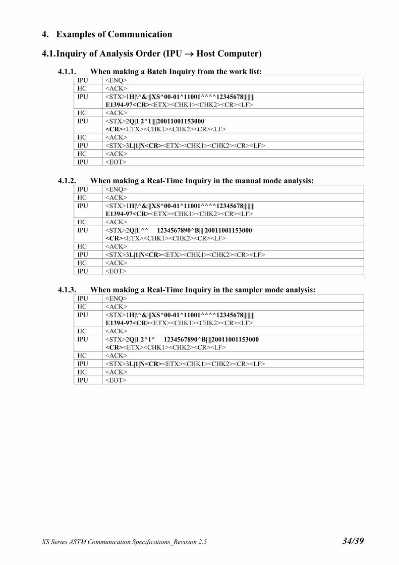
4. Examples of Communication
4.1. Inquiry of Analysis Order (IPU Host Computer)
4.1.1. When making a Batch Inquiry from the work list: IPU <ENQ> HC <ACK> IPU <STX>1H|\^&|||XS^00-01^11001^^^^12345678||||||||
E1394-97<CR><ETX><CHK1><CHK2><CR><LF> HC <ACK> IPU <STX>2Q|1|2^1||||20011001153000
<CR><ETX><CHK1><CHK2><CR><LF> HC <ACK> IPU <STX>3L|1|N<CR><ETX><CHK1><CHK2><CR><LF> HC <ACK> IPU <EOT>
4.1.2. When making a Real-Time Inquiry in the manual mode analysis:
IPU <ENQ> HC <ACK> IPU <STX>1H|\^&|||XS^00-01^11001^^^^12345678||||||||
E1394-97<CR><ETX><CHK1><CHK2><CR><LF> HC <ACK> IPU <STX>2Q|1|^^ 1234567890^B||||20011001153000
<CR><ETX><CHK1><CHK2><CR><LF> HC <ACK> IPU <STX>3L|1|N<CR><ETX><CHK1><CHK2><CR><LF> HC <ACK> IPU <EOT>
4.1.3. When making a Real-Time Inquiry in the sampler mode analysis:
IPU <ENQ> HC <ACK> IPU <STX>1H|\^&|||XS^00-01^11001^^^^12345678||||||||
E1394-97<CR><ETX><CHK1><CHK2><CR><LF> HC <ACK> IPU <STX>2Q|1|2^1^ 1234567890^B||||20011001153000
<CR><ETX><CHK1><CHK2><CR><LF> HC <ACK> IPU <STX>3L|1|N<CR><ETX><CHK1><CHK2><CR><LF> HC <ACK> IPU <EOT>

XS Series ASTM Communication Specifications_Revision 2.5 35/39
4.2. Analysis Information (Host Computer IPU)
4.2.1. When an Analysis Order exists: HC <ENQ> IPU <ACK> HC <STX>1H|\^&|||||||||||E1394-97<CR><ETX><CHK1><CHK2><CR><LF> IPU <ACK> HC <STX>2P|1|||100|^Heisei^Taro||20010820|M|||||^Dr.1||||||||||||^^^WEST
<CR><ETX><CHK1><CHK2><CR><LF> IPU <ACK> HC <STX>3C|1||patient_comments<CR><ETX><CHK1><CHK2><CR><LF> IPU <ACK> HC <STX>4O|1|2^1^ 1234567890^B||^^^^WBC\^^^^RBC\^^^^HGB\^^^^HCT\
^^^^MCV\^^^^MCH\^^^^MCHC\^^^^PLT\^^^^NEUT%\^^^^LYMPH%\ ^^^^MONO%\^^^^EO%\^^^^BASO%\^^^^NEUT#\^^^^LYMPH#\^^^^MONO#\ ^^^^EO#\^^^^BASO#\^^^^RDW-SD\^^^^RDW-CV\^^^^PDW\^^^^MPV\ ^^^^P-LCR\^^<ETB><CHK1><CHK2><CR><LF>
IPU <ACK> HC <STX>5^^PCT||20010807101000|||||N||||||||||||||Q<CR>
<ETX><CHK1><CHK2><CR><LF> IPU <ACK> HC <STX>6C|1||specimen_comments<CR><ETX><CHK1><CHK2><CR><LF> IPU <ACK> HC <STX>7L|1|N<CR><ETX><CHK1><CHK2><CR><LF> IPU <ACK> HC <EOT>
4.2.2. When no Analysis Order exists:
HC <ENQ> IPU <ACK> HC <STX>1H|\^&|||||||||||E1394-97<CR><ETX><CHK1><CHK2><CR><LF> IPU <ACK> HC <STX>2P|1<CR><ETX><CHK1><CHK2><CR><LF> IPU <ACK> HC <STX>3O|1|2^1^ 1234567890^B||||20010910101000|||||||||||||||||||Y<CR>
<ETX><CHK1><CHK2><CR><LF> IPU <ACK> HC <STX>4L|1|N<CR><ETX><CHK1><CHK2><CR><LF> IPU <ACK> HC <EOT>

XS Series ASTM Communication Specifications_Revision 2.5 36/39
4.3. Analysis Results and QC Results (IPU Host Computer)
4.3.1. Transmitting Analysis Results: IPU <ENQ> HC <ACK> IPU <STX>1H|\^&|||XS^00-01^11001^^^^12345678||||||||
E1394-97<CR><ETX><CHK1><CHK2><CR><LF> HC <ACK> IPU <STX>2P|1|||100|^Heisei^Taro||20010820|M|||||^Dr.1||||||||||||^^^WEST
<CR><ETX><CHK1><CHK2><CR><LF> HC <ACK> IPU <STX>3C|1||patient_comments<CR><ETX><CHK1><CHK2><CR><LF> HC <ACK> IPU <STX>4O|1|2^1^ 1234567890^B||^^^^WBC\^^^^RBC\^^^^HGB\^^^^HCT\
^^^^MCV\^^^^MCH\^^^^MCHC\^^^^PLT\^^^^NEUT%\^^^^LYMPH%\ ^^^^MONO%\^^^^EO%\^^^^BASO%\^^^^NEUT#\^^^^LYMPH#\^^^^MONO#\ ^^^^EO#\^^^^BASO#\^^^^RDW-SD\^^^^RDW-CV\^^^^PDW\^^^^MPV\ ^^^^P-LCR\^^<ETB><CHK1><CHK2><CR><LF>
HC <ACK> IPU <STX>5^^PCT|||||||N||||||||||||||Q<CR><ETX><CHK1><CHK2><CR><LF> HC <ACK> IPU <STX>6C|1||specimen_comments<CR><ETX><CHK1><CHK2><CR><LF> HC <ACK> IPU <STX>7R|1|^^^^WBC^1|7.81|10*3/uL||N||||||20010806120000<CR>
<ETX><CHK1><CHK2><CR><LF> HC <ACK> IPU <STX>0R|2|^^^^RBC^1|----|10*6/uL||A||||||20010806120000<CR>
<ETX><CHK1><CHK2><CR><LF> HC <ACK> IPU <STX>1R|3|^^^^HGB^1|20.5|g/dL||W||||||20010806120000<CR>
<ETX><CHK1><CHK2><CR><LF> HC <ACK> IPU <STX>2R|4|^^^^HCT^1|40.3|%||W||||||20010806120000<CR>
<ETX><CHK1><CHK2><CR><LF> HC <ACK> (Omitted) IPU <STX>7R|33|^^^^PLT_Abn_Distribution||||A||||||20010806120000
<CR><ETX><CHK1><CHK2><CR><LF> HC <ACK> IPU <STX>0R|34|^^^^Blasts?|0||||||||||20010806120000<CR>
<ETX><CHK1><CHK2><CR><LF> HC <ACK> IPU <STX>1R|35|^^^^Immature_Gran?|40||||||||||20010806120000
<CR><ETX><CHK1><CHK2><CR><LF> HC <ACK> IPU <STX>2R|36|^^^^Left_Shift?|0||||||||||20010806120000
<CR><ETX><CHK1><CHK2><CR><LF> HC <ACK> IPU <STX>3R|37|^^^^Atypical_Lympho?|0||||||||||20010806120000
<CR><ETX><CHK1><CHK2><CR><LF> HC <ACK> IPU <STX>4R|38|^^^^Abn_Lympho?|10|||A||||||20010806120000
<CR><ETX><CHK1><CHK2><CR><LF> HC <ACK> (Omitted) IPU <STX>4R|46|^^^^ACTION_MESSAGE_Delta||||A<CR><ETX><CHK1><CHK2>
<CR><LF> HC <ACK> IPU <STX>5R|47|^^^^SCAT_DIFF|PNG&R&20010806&R&2001_08_06_12_00_1234567890_
DIFF.PNG|||N||||||20010806120000<CR><ETX><CHK1><CHK2><CR><LF> HC <ACK>

XS Series ASTM Communication Specifications_Revision 2.5 37/39
(Omitted) IPU <STX>5L|1|N<CR><ETX><CHK1><CHK2><CR><LF> HC <ACK> IPU <EOT>
4.3.2. Transmitting QC Result in real-time mode:
IPU <ENQ> HC <ACK> IPU <STX>1H|\^&|||XS^00-01^11001^^^^12345678||||||||
E1394-97<CR><ETX><CHK1><CHK2><CR><LF> HC <ACK> IPU <STX>2P|1<CR><ETX><CHK1><CHK2><CR><LF> HC <ACK> IPU <STX>3O|1||^^ QC-12345678^B|^^^^WBC\^^^^RBC\^^^^HGB\^^^^HCT\
^^^^MCV\^^^^MCH\^^^^MCHC\^^^^PLT\^^^^NEUT%\^^^^LYMPH%\ ^^^^MONO%\^^^^EO%\^^^^BASO%\^^^^NEUT#\^^^^LYMPH#\^^^^MONO#\ ^^^^EO#\^^^^BASO#\^^^^RDW-SD\^^^^RDW-CV\^^^^PDW\^^^^MPV\ ^^^^P-LCR\^^^^<ETB><CHK1><CHK2><CR><LF>
HC <ACK> IPU <STX>4PCT|||||||Q||||||||||||||F<CR>
<ETX><CHK1><CHK2><CR><LF> HC <ACK> IPU <STX>5R|1|^^^^WBC^1|7.58|10*3/uL||N||||||20010806120000<CR>
<ETX><CHK1><CHK2><CR><LF> HC <ACK> IPU <STX>6R|2|^^^^RBC^1|4.49|10*6/uL||N||||||20010806120000<CR>
<ETX><CHK1><CHK2><CR><LF> HC <ACK> IPU <STX>7R|3|^^^^HGB^1|13.3|g/dL||N||||||20010806120000<CR>
<ETX><CHK1><CHK2><CR><LF> HC <ACK> IPU <STX>0R|4|^^^^HCT^1|37.3|%||N||||||20010806120000<CR>
<ETX><CHK1><CHK2><CR><LF> HC <ACK> (Omitted) IPU <STX>5R|33|^^^^SCAT_DIFF|PNG&R&20010806&R&2001_08_06_12_00_123456789
0_DIFF.PNG|||N||||||20010806120000<CR><ETX><CHK1><CHK2><CR><LF> HC <ACK> (Omitted) IPU <STX>1L|1|N<CR><ETX><CHK1><CHK2><CR><LF> HC <ACK> IPU <EOT>

XS Series ASTM Communication Specifications_Revision 2.5 38/39
4.3.3. Transmitting QC Result in a manual batch mode: IPU <ENQ> HC <ACK> IPU <STX>1H|\^&|||XS^00-01^11001^^^^12345678||||||||
E1394-97<CR><ETX><CHK1><CHK2><CR><LF> HC <ACK> IPU <STX>2P|1<CR><ETX><CHK1><CHK2><CR><LF> HC <ACK> IPU <STX>3
O|1||^^1|^^^^WBC\^^^^RBC\^^^^HGB\^^^^HCT\^^^^MCV\^ ^^^MCH\^^^^MCHC\^^^^PLT\^^^^NEUT%\^^^^LYMPH%\^^^^M NO%\^^^^EO%\^^^^BASO%\^^^^NEUT#\^^^^LYMPH#\^^^^MO ONO#\^^^^EO#\^^^^BASO#\^^^^RDW-SD\^^^^RDW-CV\^^^^PD W\^^^^MPV\^^^^P-LCR\^^^^PCT\^^^^DIFF-X\^ <ETB><CHK1><CHK2><CR><LF>
HC <ACK> IPU <STX>4^^^DIFF-Y\^^^^FSC-X|||||||Q||||||||||||||F<CR>
<ETX><CHK1><CHK2><CR><LF> HC <ACK> IPU <STX>5R|1|^^^^WBC^1|7.58|10*3/uL||N||||||20010806120000<CR>
<ETX><CHK1><CHK2><CR><LF> HC <ACK> IPU <STX>6R|2|^^^^RBC^1|4.49|10*6/uL||N||||||20010806120000<CR>
<ETX><CHK1><CHK2><CR><LF> HC <ACK> IPU <STX>7R|3|^^^^HGB^1|13.3|g/dL||N||||||20010806120000<CR>
<ETX><CHK1><CHK2><CR><LF> HC <ACK> IPU <STX>0R|4|^^^^HCT^1|37.3|%||N||||||20010806120000<CR>
<ETX><CHK1><CHK2><CR><LF> HC <ACK> (Omitted) IPU <STX>0L|1|N<CR><ETX><CHK1><CHK2><CR><LF> HC <ACK> IPU <EOT>

XS Series ASTM Communication Specifications_Revision 2.5 39/39
Appendix A. TCP/IP Communication
A.1 Network Interface Layer The network interface conforms to IEEE802.3. Communication is performed by 10Base-T. The RJ45 socket is used in a hub to connect with the IPU of XS. The cable of UTP category 5 should be used for communication.
A.2 TCP/IP
The IP address of the IPU for XS is fixed. The default value is 192.168.28.150. When this value is to be changed, please contact a Sysmex technical representative. The IP address for the host computer can be set using the setting screen in the IPU of XS. This IP address is fixed but can be changed by the setting screen in the IPU. The IP address may be selected other than “192.168.28.*” that is used to communicate with the IPU of the analyzer. The TCP port number of the IPU of XS for host communication is fixed. The default value is 6000. This value may be changed in the IPU setting screen.
A.3 Transmission Timing
Either a real-time transmission upon completion of each analysis, or a batch transmission from the stored data.
A.4 Transmission Messages
• When using ASTM E1381-95 mode: Based on the TCP/IP protocol, records defined by the presentation layer are transmitted to exchange messages. When transmitting, TCP connection has to be established. If not established, the IPU will start communication session in prior to the transmission. Messages exchanged are the records defined in the presentation layer, as listed in the following example.
(Example) Real-Time Inquiry:
IPUHC H|\^&|||XS^00-22^11001^^^^12345678||||||||E1394-97<CR> Q|1|2^1^ 1234567890^B||||20011001153000<CR> L|1|N<CR>
HCIPU H|\^&|||||||||||E1394-97<CR> P|1|||100|^Heisei^Taro||20010820|M|||||^Dr.1||||||||||||^^^WEST<CR> C|1||patient_comments<CR> O|1|2^1^ 1234567890^B||^^^^WBC\^^^^RBC\^^^^HGB\^^^^HCT\ ^^^^MCV\^^^^MCH\^^^^MCHC\^^^^PLT\^^^^NEUT%\^^^^LYMPH%\ ^^^^MONO%\^^^^EO%\^^^^BASO%\^^^^NEUT#\^^^^LYMPH#\^^^^MONO#\ ^^^^EO#\^^^^BASO#\^^^^RDW-SD\^^^^RDW-CV\^^^^PDW\^^^^MPV\ ^^^^P-LCR\^^^^PCT||20010807101000|||||N||||||||||||||Q<CR> C|1||specimen_comments<CR> L|1|N<CR>
Note that <CR> in the above example indicates “0D”, and no carriage return code is placed at the place where the text line is carriage returned in the above example.
• When using ASTM E1381-02 mode: Sending/receiving of the record defined by the presentation layer based on the protocol of 3.2 Data Link Layer (transmission protocol). When receiving or transmitting a signal, it is necessary that the TCP connection has been established. If it has not been established, the IPU automatically starts a session before sending the signal. For examples of messages sent/received, refer to the samples in 4 Examples of Communication. (However, the record division size sent by the IPU for serial connection is different than the size for TCP/IP. See 3.2.3 Transfer Phase.)
[ end of document ]