xp pressure monitor kit 3a1331b - graco inc. · pdf filexp pressure monitor kit 3a1331b eng...
TRANSCRIPT

Instructions-Parts
3A1331BXP Pressure Monitor KitENG
Monitor s pressures to provide ratio assurance on XP plural-component sprayers. Forprofessional use onl y. Not approved for use in explosive atmosphere locations.
Impor tant Safety InstructionsRead all warnings and instructions in this manualand the XP sprayer operation manual.Save these instructions.
Models262940:Line Power Pressure Monitor Kit with Light Tower
262942:Air Turbine Power Pressure Monitor Kit with Light Tower
PROVEN QUALITY. LEADING TECHNOLOGY.

ContentsContentsContentsOverview............................................................ 3
Operating Window ....................................... 3Component Identification..................................... 4
262940 Line Power Kit ................................. 4262942 Air Turbine Kit.................................. 5User Interface .............................................. 6
Installation.......................................................... 7Location ...................................................... 7Install Air Solenoid ....................................... 7Install Electronics Box and LCM.................... 8Install Pressure Transducers ........................ 8Connect Air Hoses and Cables ..................... 9
Startup............................................................... 9Shutdown........................................................... 9Advisories and Alarms ........................................ 10
Clear Alarms................................................ 10View Current Alarms .................................... 10View Error Log............................................. 11Error Codes................................................. 12
Repair................................................................ 15
Replace LCM Tear Off Sheet ........................ 15Replace Switch Fuses.................................. 15Replace Filter Element ................................. 15Replace Alternator or Turbine
Cartridge........................................ 16
Notes ............................................................... 17
Parts.................................................................. 18
Appendix A— User Interface Display ................... 22Setup Mode Details...................................... 22
Set Password........................................ 24Run Mode Details ........................................ 25
Circulation Mode Active ......................... 25Spray Mode Active ................................ 25Alarm Active ......................................... 25Deviation Active .................................... 26
Information Screen....................................... 26
Appendix B - Breakout ModuleConnections.......................................... 27
Accessories........................................................ 28
Technical Data ................................................... 29
Graco Standard Warranty.................................... 30
2 3A1331B

OverviewOverviewOverview
Topics Covered in this Chapter
♦ Operating Window
The purpose of the pressure monitor kit is toshutdown the sprayer if abnormal pressure conditionsare detected to prevent spraying material that is notmixed on ratio.
Two pressure transducers are added to read the Aand B fluid pressures in the outlet manifold and sendthe readings back to the Local Control Module (LCM).
When your sprayer pressures indicate that it may beoff ratio, the air solenoid shuts off the air supply tothe proportioner motor. The light tower will indicatean alarm has occurred, and the alarm code willbe on the LCM display. For more information seeAdvisories and Alarms, page 10.
The following alarms can occur:
• Pressure A Disconnected
• Pressure B Disconnected
• Air Solenoid Disconnected
• Pressure A High
• Pressure B High
• Differential Pressure (A>B)
• Differential Pressure (B>A)
OperatingOperatingOperating WindowWindowWindow
BelowBelowBelow MinimumMinimumMinimum SpraySpraySpray PressurePressurePressure
The air motor is allowed to automatically operate inCirculation Mode with a yellow light anytime the fluidpressures are below the minimum spray pressure.This allows for loading the system and circulating thefluids without alarms or shutdowns.
AboveAboveAbove MinimumMinimumMinimum SpraySpraySpray PressurePressurePressure
When the control sees the fluid pressures above theminimum spray pressure for 3–30 seconds, and thepressures are balanced within the pre-set limits, itwill automatically start the monitor mode, and thegreen light on the light tower will change to solidon. If the control does not see balanced pressureswithin 30 seconds of going above the minimum spraypressure, it will alarm and shut off the air motor. Thedefault minimum spray pressure is 2000 psi (14 MPa,138 bar). Enter Setup Mode to change the minimumspray pressure as necessary.
MaximumMaximumMaximum SpraySpraySpray PressurePressurePressure
The control will alarm and shutdown if it sees either Aor B above the maximum working pressure of 7250psi (50 MPa, 500 bar). Enter Setup Mode to reducethe maximum allowable pressure set point.
3A1331B 3
ComponentComponentComponent IdentificationIdentificationIdentification
Topics Covered in this Chapter
♦ 262940 Line Power Kit♦ 262942 Air Turbine Kit♦ User Interface
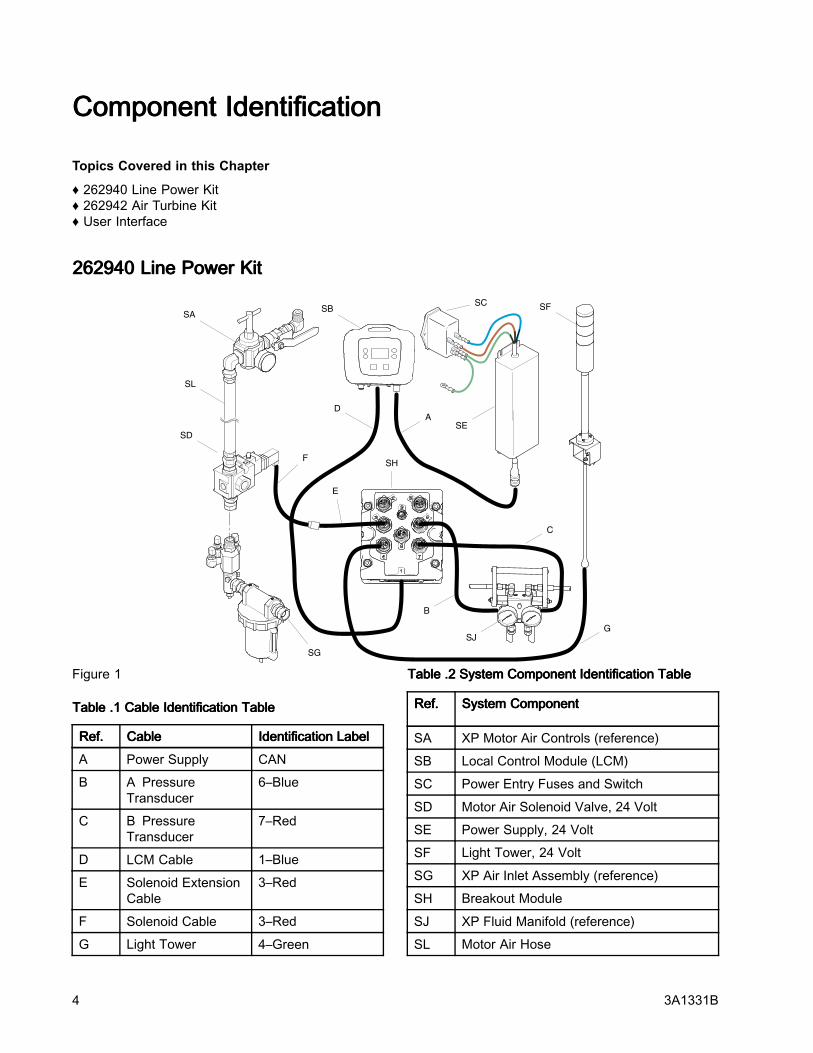
262940262940262940 LineLineLine PowerPowerPower KitKitKit
SA
SD
SG
SB
SE
SFSC
F
DA
SJ
SH
C
B
G
SL
E
Figure 1
TableTableTable .1.1.1 CableCableCable IdentificationIdentificationIdentification TableTableTable
Ref.Ref.Ref. CableCableCable IdentificationIdentificationIdentification LabelLabelLabel
A Power Supply CAN
B A PressureTransducer
6–Blue
C B PressureTransducer
7–Red
D LCM Cable 1–Blue
E Solenoid ExtensionCable
3–Red
F Solenoid Cable 3–Red
G Light Tower 4–Green
TableTableTable .2.2.2 SystemSystemSystem ComponentComponentComponent IdentificationIdentificationIdentification TableTableTable
Ref.Ref.Ref. SystemSystemSystem ComponentComponentComponent
SA XP Motor Air Controls (reference)
SB Local Control Module (LCM)
SC Power Entry Fuses and Switch
SD Motor Air Solenoid Valve, 24 Volt
SE Power Supply, 24 Volt
SF Light Tower, 24 Volt
SG XP Air Inlet Assembly (reference)
SH Breakout Module
SJ XP Fluid Manifold (reference)
SL Motor Air Hose
4 3A1331B
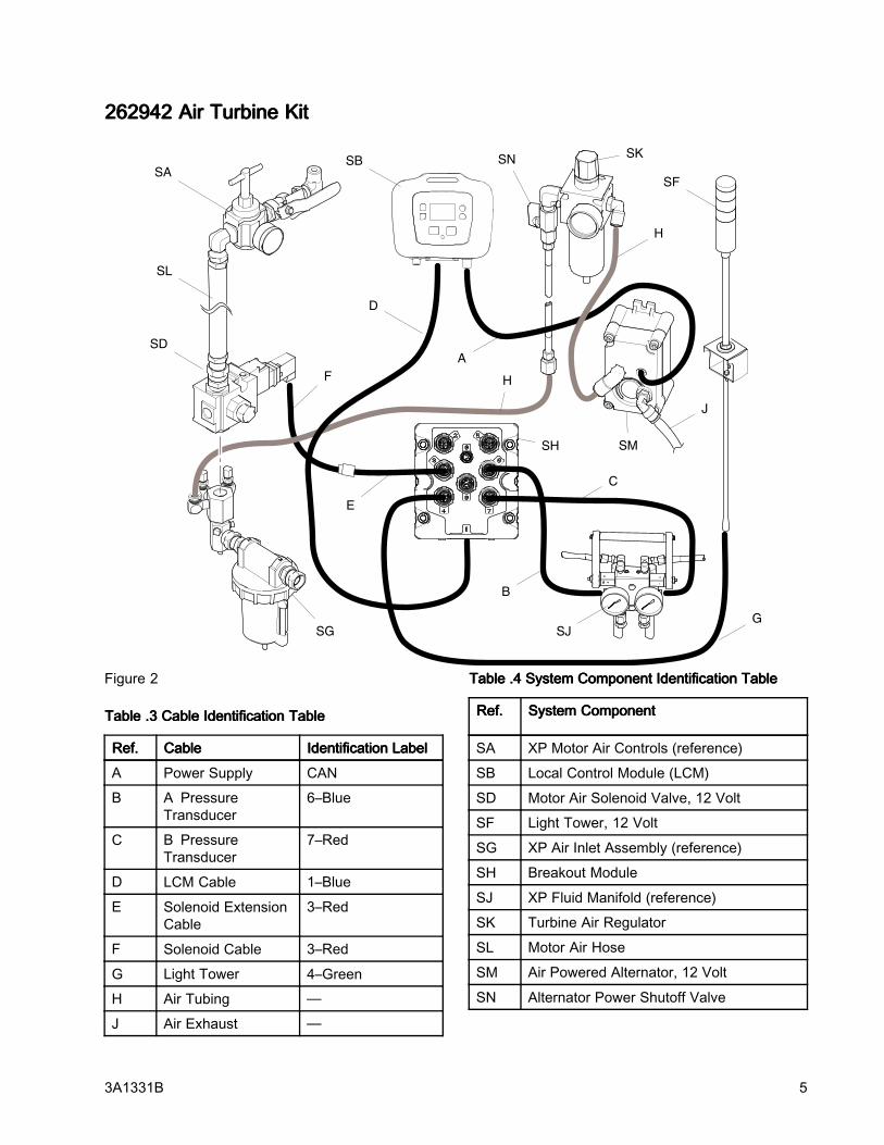
262942262942262942 AirAirAir TurbineTurbineTurbine KitKitKit
SA
SD
SG
SB
SF
F
D
SJ
SH
C
B
G
SL
J
H
SN
E
A
H
SM
SK
Figure 2
TableTableTable .3.3.3 CableCableCable IdentificationIdentificationIdentification TableTableTable
Ref.Ref.Ref. CableCableCable IdentificationIdentificationIdentification LabelLabelLabel
A Power Supply CAN
B A PressureTransducer
6–Blue
C B PressureTransducer
7–Red
D LCM Cable 1–Blue
E Solenoid ExtensionCable
3–Red
F Solenoid Cable 3–Red
G Light Tower 4–Green
H Air Tubing —
J Air Exhaust —
TableTableTable .4.4.4 SystemSystemSystem ComponentComponentComponent IdentificationIdentificationIdentification TableTableTable
Ref.Ref.Ref. SystemSystemSystem ComponentComponentComponent
SA XP Motor Air Controls (reference)
SB Local Control Module (LCM)
SD Motor Air Solenoid Valve, 12 Volt
SF Light Tower, 12 Volt
SG XP Air Inlet Assembly (reference)
SH Breakout Module
SJ XP Fluid Manifold (reference)
SK Turbine Air Regulator
SL Motor Air Hose
SM Air Powered Alternator, 12 Volt
SN Alternator Power Shutoff Valve
3A1331B 5

UserUserUser InterfaceInterfaceInterface
Figure 3
TableTableTable .5.5.5 LCMLCMLCM ButtonButtonButton FunctionsFunctionsFunctions
ButtonButtonButton FunctionFunctionFunction
Mode Select between Run and SetupModes.
Spray Start and stop the air motor. Themotor will stay on indefinitely ifpressures are below minimumspray pressure. Monitor modewill start within 30 seconds if thepressures are above the minimumspray pressure and no errors exist.All errors are ignored for up to thefirst 30 seconds. Default is 2000psi (138 MPa, 138 bar)
ArrowsUp/Down
Navigate up or down within ascreen or to a new screen.
Soft keys activate the mode oraction represented by the icon nextto each soft key.
See Table 2 for soft key icons andactions.
Top Soft Key: Edit data, acceptedited data, or move right within anumber field.
Soft Keys
Bottom Soft Key: Enter a screen,exit a screen, or cancel edited data.
NOTICENOTICENOTICETo prevent damage to soft key buttons, do notpress the buttons with sharp objects such as pens,plastic cards, or fingernails.
TableTableTable .6.6.6 DisplayDisplayDisplay SoftSoftSoft KeyKeyKey IconsIconsIcons
IconIconIcon FunctionFunctionFunction
Enter Screen In screens that have editable fields,press to access the fields andmake changes.
Exit Screen In screens that have editable fields,press to exit edit mode.
Enter In screens that have editable fields,press to make data selections orto enter changes.
Right In screens that have editable fields,press to move to the right while ina field.
Cancel Cancel a selection or edited data.Returns to the original data.
Clear ErrorLog
Clear entire error log..
6 3A1331B

InstallationInstallationInstallation
Topics Covered in this Chapter
♦ Location♦ Install Air Solenoid♦ Install Electronics Box and LCM♦ Install Pressure Transducers♦ Connect Air Hoses and Cables
Shutdown the XP Sprayer before installing yourpressure monitor kit. Follow the ShutdownShutdownShutdown andPressurePressurePressure ReliefReliefRelief ProcedureProcedureProcedure in the XP Sprayeroperation manual. All electrical wiring must bedone by a qualified electrician and comply with alllocal codes and regulations.
The procedures in this section are specific to eachcomponent of the pressure monitor kit. For sprayerinstallation instructions, refer to the XP70 SprayerOperation manual.
LocationLocationLocation
These pressure monitoring kits are not approvedfor use in hazardous atmosphere locations.
Installing this kit on a XP Sprayer that is EXapproved, voids the approval. The EX mark shouldbe removed from the machine ID plate when thiskit is installed.
NOTICENOTICENOTICEDo not store a XP Sprayer with a pressure monitorkit outside in the rain. Use protective bag 16J717to prevent damage to the electronic components,used with the pressure monitor kit, when storedoutside.
InstallInstallInstall AirAirAir SolenoidSolenoidSolenoid
1. Disconnect the upper swivel and remove themotor air line from the lower air manifold.
NoteNoteNote
On early XP sprayers, to remove theexisting air hose, it may be necessary toremove the air filter assembly from theXP and put it in a vice. New models XPsprayers have an additional hose union.
2. For the turbine powered kit 262942, remove aplug from the air manifold and install the 5/16 in.x 4 ft (1.2 m) air hose.
Figure 4
3. Connect the air solenoid valve and new motorair hose to the air inlet assembly. Ensure thatthe air solenoid valve cable faces the back ofthe machine.
3A1331B 7

InstallInstallInstall ElectronicsElectronicsElectronics BoxBoxBox andandand LCMLCMLCM
Early XP carts have two mounting holes and new XPcarts have three mounting holes. Complete steps 1and 2 to drill a third mounting hole for the pressuremonitor kit. Complete step 2 if you have a new XPcart.
1. EarlyEarlyEarly XPXPXP cartscartscarts withwithwith twotwotwo mountingmountingmounting holesholesholes
a. Use two screws (61) and two nuts (62) tomount the electronics box to the top of thecart.
b. Use a marker to mark the bracket’s thirdmounting hole.
c. Loosen the nuts (62) below the cart shelf andremove the screws (61), and box bracket.Center punch and drill a 5/16 in. hole in thetop of the cart.
2. NewNewNew XPXPXP cartscartscarts withwithwith threethreethree mountingmountingmounting holes.holes.holes.
a. Use three screws (61) and three nuts (62) tomount the box bracket to the cart.
b. For power supply kits, install the appropriatepower supply cord(s). US, European, andAustralia/Asia cord adapters are supplied.See Technical Data, page 29.
Early XP Cart InstallationFigure 5
InstallInstallInstall PressurePressurePressure TransducersTransducersTransducers
1. Remove plugs from the circulation manifold.
NoteNoteNote
Keep plugs if you will ever remove thepressure monitor kit.
2. Connect pressure transducer (4), with blue#6 label, with black o-ring (13) to the A sideof the circulation manifold. Connect pressuretransducer (4), with red #7 label, with black o-ring(13) to the B side of the circulation manifold.Tighten to 40–50 ft-lb (54–67 N•m) beforeapplying fluid pressure. Pressure Transducers
Figure 6
8 3A1331B

ConnectConnectConnect AirAirAir HosesHosesHoses andandand CablesCablesCables
Reference 262940 Line Power Kit, page 4 and262942 Air Turbine Kit, page 5 for air hose andcable connections.
Use tie wraps provided to secure hose and cables.For turbine kit 262942, route exhaust hose down cartleg and secure.
• 262942: Secure solenoid cable (F) to air hoseswith tie wrap. Route exhaust hose (J) down theinside of the cart leg and secure with tie wrap.
• 262940: Route solenoid cable (F) behind the airhose and secure with tie wrap.
StartupStartupStartup
1. Refer to your XP Sprayer Operation manual forsprayer startup instructions.
NoteNoteNote
The pressure monitor kit modifies XPsprayers. However, the operationprocedures from the XP sprayerOperation manual still apply.
2. Turn on power.
a. For 262940: Turn on power switch (9)located on the electronics box.
b. For 262942: Open ball valve (22) locatedoutside of the electronics box.
3. Wait for the power up screen to complete. TheCirculation Mode screen will display. The lighttower will briefly flash green, yellow, and red toverify the lights before staying on yellow. Wait forthe run screen to appear.
4. Set system parameters before spraying.These can be changed as necessary.
Press to enter Setup Mode. For
more information and default settings, seeSetup Mode Details, page 22.
5. In Circulation Mode, all alarms are disabledexcept for the air solenoid detection, pressuresensor failure, and high pressure alarms.
NoteNoteNote
In Manual Bypass Mode you can stillspray when one pressure transducerfails, but the control no longer monitorsthe pressures and will not shut off thesprayer. This is for emergency only.
a. To enter Manual Bypass Mode, set theminimum spray pressure equal to themaximum spray pressure on setup screen2. In Manual Bypass Mode, the system cannever get into Spray Mode. The event codeEVC1 is displayed on the information screenand logged in the error log. The yellow lightis always on and all alarms are ignored.
b. To exit Manual Bypass Mode, set themimimum spray pressure and maximumspray pressure to different spray pressures.Event code EVC0 will log in the error logwhen Bypass Mode is disabled.
6. Press to start the air motor. The red LEDwill turn on and the motor will start. Only spraywhen the green light on the light tower is on. Formore information about the LCM run screens,see Run Mode Details, page 25.
ShutdownShutdownShutdown
1. Press . The red LED will turn off and themotor will stop.
2. Turn off the power switch or ball valve on theoutside of the electronics box.
3A1331B 9

AdvisoriesAdvisoriesAdvisories andandand AlarmsAlarmsAlarms
Topics Covered in this Chapter
♦ Clear Alarms♦ View Current Alarms♦ View Error Log♦ Error Codes
There are three types of errors that can occur. Errorsare indicated by the light tower as well as on thedisplay.
Alarms indicated by , require immediateattention; therefore, the control disables the air motorand the Information screen automatically displays.
Deviations, indicated by , require attention, butnot immediately.
Advisories, indicated by , do not requireattention. Therefore, if a deviation or advisory occur,
the system continues running and ordisplays next to the operation mode field.
The following table explains the error type that isassociated with the particular light tower LED.
LightLightLight TowerTowerTowerLEDLEDLED
DescriptionDescriptionDescription
Green Solid System is powered up andmonitoring pressure.
Yellow Solid In Circulation Mode or Manual
Bypass Mode
YellowFlashing
A deviation exists
Red Solid An alarm exists and the system
shuts down
ClearClearClear AlarmsAlarmsAlarms
Fore more information about the alarms, seeInformation Screen, page 26.
To clear an error:
1. Press to clear the alarm.
2. Press to restart the air motor.
ViewViewView CurrentCurrentCurrent AlarmsAlarmsAlarms
From the Run screen, press to navigateto the Information screen. The Information screendisplays current alarms or advisories.
Figure 7
10 3A1331B

ViewViewView ErrorErrorError LogLogLog
Setup Screen 3 is the error log screen. It displays themost recent error on the top of the list with the pastthree errors below it. This screen displays a list ofadvisory or alarm error codes and the time the erroroccurred since the kit was powered on.
3A1331B 11

ErrorErrorError CodesCodesCodes
CodeCodeCode IconIconIcon CodeCodeCode NameNameName LightLightLight TowerTowerTowerCodeCodeCode
CauseCauseCause SolutionSolutionSolution
AlarmsAlarmsAlarms
Ran out of B sidematerial.
Refill hopper orchange drum.
Cavitating B sidepump.
Warm material or addfeed pressure.
B material leaking. Follow pumptroubleshooting inXP70 Sprayer manual.
No mix manifold Bside restriction.
Add restriction to Bside on mix manifoldto balance pressures.
A side hose is toosmall.
Change to larger hosesize.
J4AXJ4AXJ4AX Differential Pressure(A>B)
Red Solid
Improperconfiguration.
Adjust setpoints onsetup screens. SeeSetup Mode Details,page 22.
Ran out of A sidematerial.
Refill hopper orchange drum.
Cavitating A sidepump.
Warm material or addfeed pressure.
A material leaking. Follow pumptroubleshooting inXP70 Sprayer manual.
Too much restrictionon mix manifold B siderestriction.
Reduce restriction to Bside on mix manifold.
* Bside hose is toosmall.
Change to largerdiameter hose size.
* No B side offset incontrol setup.
Adjust B side offsetin setup screens ifB normally runs at ahigher pressure thanA. See Setup ModeDetails, page 22.
J4BXJ4BXJ4BX Differential Pressure(B>A)
Red Solid
Improperconfiguration.
Adjust setpoints onsetup screens. SeeSetup Mode Details,page 22.
Broken cable. Replace transducer.P6AXP6AXP6AX Pressure ADisconnected
Red Solid
Disconnected cable. Connect cable.
12 3A1331B
CodeCodeCode IconIconIcon CodeCodeCode NameNameName LightLightLight TowerTowerTowerCodeCodeCode
CauseCauseCause SolutionSolutionSolution
AlarmsAlarmsAlarms
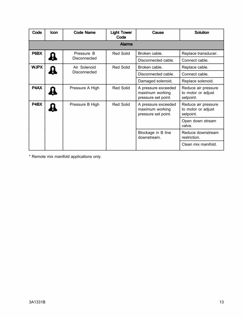
Broken cable. Replace transducer.P6BXP6BXP6BX Pressure BDisconnected
Red Solid
Disconnected cable. Connect cable.
Broken cable. Replace cable.
Disconnected cable. Connect cable.
WJPXWJPXWJPX Air SolenoidDisconnected
Red Solid
Damaged solenoid. Replace solenoid.
P4AXP4AXP4AX Pressure A High Red Solid A pressure exceededmaximum workingpressure set point.
Reduce air pressureto motor or adjustsetpoint.
Reduce air pressureto motor or adjustsetpoint.
A pressure exceededmaximum workingpressure set point.
Open down streamvalve.
Reduce downstreamrestriction.
P4BXP4BXP4BX Pressure B High Red Solid
Blockage in B linedownstream.
Clean mix manifold.
* Remote mix manifold applications only.
3A1331B 13

CodeCodeCode IconIconIcon CodeCodeCode NameNameName LightLightLight TowerTowerTowerCodeCodeCode
CauseCauseCause SolutionSolutionSolution
DeviationsDeviationsDeviations
Ran out of B sidematerial.
Refill hopper orchange drum.
Cavitating B sidepump.
Warm material or addfeed pressure.
B material leaking. Follow pumptroubleshooting inXP70 Sprayer manual.
No mix manifold Bside restriction.
Add restriction to Bside on mix manifoldto balance pressures.
J3AXJ3AXJ3AX Differential Pressure(A>B)
YellowFlashing
A side hose is toosmall.
Change to larger hosesize.
Ran out of A sidematerial.
Refill hopper orchange drum.
Cavitating A sidepump.
Warm material or addfeed pressure.
A material leaking. Follow pumptroubleshooting inXP70 Sprayer manual.
Too much restrictionon mix manifold B siderestriction.
Reduce restrictionto GB side on mixmanifold.
* B side hose toosmall.
Change to larger hosesize.
J3BXJ3BXJ3BX Differential Pressure(B>A)
YellowFlashing
* No B side offset incontrol setup.
Add B side offset insetup screen.
EventsEventsEvents andandand AdvisoriesAdvisoriesAdvisories
EERXEERXEERX Under Minimum SprayPressure, Circulation,
Loading
Yellow Under minimum spraypressure.
Normal for circulationmode.
EVC0EVC0EVC0 Manual Bypass ModeEnabled and Logged.Minimum Pressure =Maximum Pressure
Yellow
Manual Bypass Mode
Reset minimumspray pressure andmaximum spraypressure in Setup
Mode.
EVC1EVC1EVC1 — Manual Bypass ModeDisabled and Logged
— Event log only —
ELCXELCXELCX—
Control Power UpTimer set to zero
in Log
—Event log only —
* Remote mix manifold applications only.
14 3A1331B

RepairRepairRepair
Topics Covered in this Chapter
♦ Replace LCM Tear Off Sheet♦ Replace Switch Fuses♦ Replace Filter Element♦ Replace Alternator or Turbine Cartridge
For system specific repair procedures, refer to yourXP Sprayer instructions-parts manual.
ReplaceReplaceReplace LCMLCMLCM TearTearTear OffOffOff SheetSheetSheet
The LCM is supplied with 10 protective tear off sheetsthat prevent spray material from covering the LCMdisplay.
1. Peel away the dirty protective sheet.
2. Install a new protective sheet (68) on the LCMdisplay.
Figure 8
ReplaceReplaceReplace SwitchSwitchSwitch FusesFusesFuses
ForForFor 262940262940262940 only.only.only.
1. Remove power inlet cord (55 or 57).
2. Pry off small plastic cover above cord inlet.
3. Pull fuses (63) out of power switch. Replace andreassemble.
Figure 9
ReplaceReplaceReplace FilterFilterFilter ElementElementElement
There is a 5 micron air filter used with the regulatoron the alternator power kit 262942. Check the filtermonthly and replace element as needed.
1. Close main air shutoff valve on air supply lineand on unit. Depressurize air line.
2. Remove box cover (30).
3. Press silver tab in, twist bowl to the left, and pulldown off of the regulator.
4. Remove and replace element.
5. Screw filter bowl on securely until the tab clicks.
Figure 10
3A1331B 15

ReplaceReplaceReplace AlternatorAlternatorAlternator ororor TurbineTurbineTurbineCartridgeCartridgeCartridge
ForForFor 262942262942262942 only.only.only.
Turbine alternator cartridge 257147 (34e) can bereplaced in alternator 262579 (34).
1. Turn off air supply.
2. Close ball valve (22).
3. Remove box cover (30).
Figure 11
4. Disconnect the alternator power supply cable (A)from the LCM (21). Disconnect ground wire (Z).
5. Disconnect air tube (40) from the alternator (34).
6. Remove two screws (15) to remove alternatorfrom the box (1).
7. Remove four screws (34d) to separate alternatorhousings.
8. Disconnect turbine cartridge ribbon connector(34e) from board (AB).
9. Replace gasket (34a) if damaged. Place betweenhousings before securing with screws (34d).
10. Reassemble.
NoteNoteNote
• Lightly lubricate turbine o-ring beforeinstalling turbine in housing.
• Align ribbon connector and firmly pressthe cartridge into the top housing.
• Connect turbine to 3–pin connector onmain circuit board.
• Torque housing screws evenly to 18in.-lbs (2 N•m).
• Reassemble into control box (1).
A
Z
Figure 12
34d
34a
34e
AB
Z
Figure 13
16 3A1331B

NotesNotesNotes
3A1331B 17

PartsPartsParts
262940262940262940 LineLineLine PowerPowerPower PressurePressurePressure MonitorMonitorMonitor KitKitKit
Apply sealant to all non-swiveling pipe threads.
* Already included on new XP model sprayers.
18 3A1331B

Ref.Ref.Ref. PartPartPart DescriptionDescriptionDescription Qty.Qty.Qty.
1 262457 BOX, weldment assembly 1
2 — BRACKET, top mount 1
3 15M293 POWERSUPPLY, 24VDC,2.5A, 60W, gnd wire
1
4 15M669 SENSOR, pressure, fluidoutlet
2
5 15X472 LIGHT TOWER, m12 1
6 — BRACKET, mounting,assembly
1
7 258999 MODULE, LCM, breakout 1
8 157785 SWIVEL 2
9 121254 SWITCH, power, 120V 1
11 102410 SCREW, cap, sch 4
12 100016 WASHER, lock 1
13 121399 O-RING 012, solventresistant
2
14 189930 LABEL, caution 1
15 104371 SCREW,cap sch 10X.375 4
16 104472 SCREW, cap; 10–32 x 1.5 4
17 110755 WASHER, plain 1
18 — SCREW, countersunk,6-32 x .38
2
20 110047 HOSE, coupled, 18 in.(457.2 mm)
1
21 24H286 MODULE, LCM; includes21a
1
21a 16G728 TOKEN, PM software; notshown
1
25 121253 KNOB, display adjustment 1
26 119992 NIPPLE, 3/4 x 3/4 npt 1
27 111530 MUFFLER 1
28 16G901 VALVE, 24VDC, internalpilot, 3/4
1
Ref.Ref.Ref. PartPartPart DescriptionDescriptionDescription Qty.Qty.Qty.
29 15T859 CABLE, assembly, DB25,10 ft (3 m)
1
30 — COVER, box 1
31 102063 WASHER, lock, ext 1
32 108865 SCREW, cap, button hd 1
33 121806 CABLE, solenoid 1
43 122030 CABLE, GCA, M12-5P 1
47 16H323 GROMMET, one slit 1
53 120206 MUFFLER, sintered, dia1/8
1
55 116281 CORD SET, IEC320(M-F),6 ft (1.8 m)
1
56 195551 RETAINER, plug, adapter 1
57 245202 CORD, SET, USA, 10 ft (3m), 13 AMP, 120V
1
58 242001 CORD SET, adapter,Europe; 8 in. (20 mm)
1
59 242005 CORD SET, adapter,Australia-Asia; 8 in. (20mm)
1
61 113796 SCREW, flanged, hex hd 3
62 115942 NUT, hex, flange head 3
63 121261 FUSE, 250V / 1.2A 2
65 114606 PLUG, hole 1
67 113783 SCREW, 1/4–20, pn hd 4
68 16H378 SHIELD, membrane, LCM(pack of 10)
1
69 114225 TRIM, edge protection; 0.6ft (0.18 m)
1
70 16J685 LABEL, error codes 1
Replacement Danger and Warning labels, tags,and cards are available at no cost.
3A1331B 19

262942262942262942 AirAirAir TurbineTurbineTurbine PressurePressurePressure MonitorMonitorMonitorKitKitKit
Apply sealant to all non-swiveling pipe threads.
* Already included on new XP model sprayers.
20 3A1331B
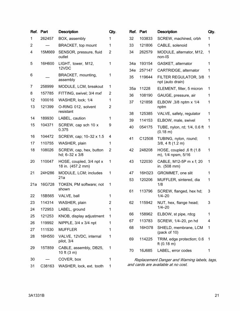
Ref.Ref.Ref. PartPartPart DescriptionDescriptionDescription Qty.Qty.Qty.
1 262457 BOX, assembly 1
2 — BRACKET, top mount 1
4 15M669 SENSOR, pressure, fluidoutlet
2
5 16H600 LIGHT, tower, M12,12VDC
1
6 — BRACKET, mounting,assembly
1
7 258999 MODULE, LCM, breakout 1
8 157785 FITTING, swivel; 3/4 mxf 2
12 100016 WASHER, lock; 1/4 1
13 121399 O-RING 012, solventresistant
2
14 189930 LABEL, caution 1
15 104371 SCREW, cap sch 10 x0.375
9
16 104472 SCREW, cap; 10–32 x 1.5 4
17 110755 WASHER, plain 1
18 108026 SCREW, cap, hex, buttonhd; 6–32 x 3/8
2
20 110047 HOSE, coupled, 3/4 npt x18 in. (457.2 mm)
1
21 24H286 MODULE, LCM; includes21a
1
21a 16G728 TOKEN, PM software; notshown
1
22 15B565 VALVE, ball 1
23 114314 WASHER, plain 2
24 172953 LABEL, ground 1
25 121253 KNOB, display adjustment 1
26 119992 NIPPLE, 3/4 x 3/4 npt 1
27 111530 MUFFLER 1
28 16H550 VALVE, 12VDC, internalpilot, 3/4
1
29 15T859 CABLE, assembly, DB25,10 ft (3 m)
1
30 — COVER, box 1
31 C38163 WASHER, lock, ext. tooth 1
Ref.Ref.Ref. PartPartPart DescriptionDescriptionDescription Qty.Qty.Qty.
32 103833 SCREW, machined, crbh 1
33 121806 CABLE, solenoid 1
34 262579 MODULE, alternator, M12,non-IS
1
34a 193154 GASKET, alternator 1
34e 257147 CARTRIDGE, alternator 1
35 119644 FILTER REGULATOR, 3/8npt (auto drain)
1
35a 11228 ELEMENT, filter, 5 micron 1
36 108190 GAUGE, pressure, air 1
37 121858 ELBOW ,3/8 nptm x 1/4nptm
1
38 125385 VALVE, safety, regulator 1
39 114153 ELBOW, male, swivel 1
40 054175 TUBE, nylon, rd; 1/4, 0.6 ft(0.18 m)
1
41 C12508 TUBING, nylon, round;3/8, 4 ft (1.2 m)
1
42 248208 HOSE, coupled ,6 ft (1.8m), 1/4 npsm, 5/16
1
43 122030 CABLE, M12-5P m x f; 20in. (508 mm)
1
47 16H323 GROMMET, one slit 1
53 120206 MUFFLER, sintered, dia1/8
1
61 113796 SCREW, flanged, hex hd;1/4–20
3
62 115942 NUT, hex, flange head;1/4–20
3
66 158962 ELBOW, st pipe, rdcg 1
67 113783 SCREW, 1/4–20, pn hd 4
68 16H378 SHIELD, membrane, LCM(pack of 10)
1
69 114225 TRIM, edge protection; 0.6ft (0.18 m)
1
70 16J685 LABEL, error codes 1
Replacement Danger and Warning labels, tags,and cards are available at no cost.
3A1331B 21

AppendixAppendixAppendix A—A—A— UserUserUser InterfaceInterfaceInterface DisplayDisplayDisplay
Topics Covered in this Chapter
♦ Setup Mode Details♦ Run Mode Details♦ Information Screen
SetupSetupSetup ModeModeMode DetailsDetailsDetails
Setup mode screens enable user to view or modifysystem configuration data. User can set:
• Units of pressure
• Differential pressure warning value
• Differential pressure alarm value
• High pressure limit value
• Minimum spray pressure value
• Normal B pressure offset value
SetupSetupSetup ScreenScreenScreen 111
Setup screen 1 enables users to set units ofmeasurement that will display on other screens,differential warning and differential alarm.Additionally, this screen displays the softwarenumber and version. Refer to the following table formore information.
IconIconIcon FunctionFunctionFunction
Warning Pressure
Adjust the differential pressuredeviation setpoint.
Default: 400 psi
Range: 0–2000 psiAlarm Pressure
Adjust the differential pressure alarmsetpoint.
Default: 600 psi
Range: 0–2000 psi
22 3A1331B

SetupSetupSetup ScreenScreenScreen 222
Setup screen 2 enables users to set the high spraypressure alarm limit value, minimum spray pressurevalue and B pressure offset. Refer to the followingtable for more information.
IconIconIcon FunctionFunctionFunction
High Pressure Limit
Adjust the high pressure limit.
Default: 7250 psi (14 MPa, 138 bar)
Range: 0-7250 psi (50 MPA, 500bar) maximum
Minimum Spray Pressure Limit
Adjust the lower spray pressure limit.
Default: 2000 psi (14 MPa, 138 bar)
Range: 0-7250 psi (50 MPA, 500bar) maximum
B Side Pressure Offset
Adjust offset pressure for remotemix manifold applications when theB pressure is normally different thanthe A pressure.
Default: 0 psi
Range: -999 to 999 psiPassword
The setup screens can be protectedby a password to restrict theiraccessibility. To set the password,see Set Password, page 24.
Range: 0-9999
SetupSetupSetup ScreenScreenScreen 333
Setup screen 3 enables users to scroll through allerrors and clear the entire error log. The error log willdisplay the most recent error on the top of the list withthe past three errors below it. Refer to the followingtable for more information.
IconIconIcon FunctionFunctionFunction
Error Number
The first column lists the errornumber. Once the system hasmore than the maximum errorsallowed, then the oldest error will beover-written.
Maximum: 99Error Code
The second column lists the errorscodes. See Error Codes, page 12.
Maximum: 99Time
The third column shows the timethat the error occurred. The timewill always start at 0:00 when thesystem is powered up. This time willbe logged as code ELCX.
Format: Hours : Minutes
Maximum: 999 : 59Reset
Press the Reset icon to clear theentire error log.
3A1331B 23

SetSetSet PasswordPasswordPassword
NoteNoteNote
When the password is “0000,” the setupscreens can be accessed without enteringa password.
1. Navigate to setup screen 2.
2. Press to access fields to make changes.
3. Press to navigate to the password field.
Press to edit data.
4. Press and to increment ordecrement to the desired digits of the password.
5. Press to accept the password or press
to cancel.
6. Press to exit edit mode.
NoteNoteNote
The password screen is shown whenthe setup screens are accessed and thepassword function has been enabled bychanging the 0000 password.
Figure 14
If you set and forget the password, pleasecontact Graco Technical Assistance for a defaultpassword.
24 3A1331B

RunRunRun ModeModeMode DetailsDetailsDetails
There are four Run Screens: Circulation ModeActive, Spray Mode Active, Alarm Active, andDeviation Active.
CirculationCirculationCirculation ModeModeMode ActiveActiveActive
If the user needs to spray with one of the above errorsactive, set the Lower Spray Pressure Limit equalto the High Pressure Alarm Limit to enter ManualBypass Mode. Only use Manual Bypass Mode foremergency operation. The control no longer monitorsthe pressures and will not shut off the sprayer.
IconIconIcon SystemSystemSystem StatusStatusStatus
Indicates that you are in CirculationMode and the fluid pressure is belowthe Lower Spray Pressure Limit.
All alarms are disabled except for AirSolenoid Detection, High PressureA, and High Pressure B alarms. Theyellow light on the light tower will besolid on.
This screen will also be used when inManual Bypass Mode.
NoteNoteNote
All alarms and deviationsare ignored in Bypass Mode.You will be allowed to spraybad material. The yellowlight will be solid on.
SpraySpraySpray ModeModeMode ActiveActiveActive
When the pressure first gets above the lower spraypressure limit, the user has 30 seconds to balancethe system differential pressure so it is less that thedifferential pressure deviation and alarm limits. Thenthe system will automatically go into Spray mode andstart monitoring all alarms and deviations.
IconIconIcon SystemSystemSystem StatusStatusStatus
Indicates that you are in spraymode, at least one of the pumps haspressure greater than the lower spraypressure limit, and the differentialpressure is less that the differentialpressure deviation setpoint.
The green light on the light tower willbe solid on.
AlarmAlarmAlarm ActiveActiveActive
IconIconIcon SystemSystemSystem StatusStatusStatus
Indicates that there is an activealarm.
The red light on the light tower will besolid on and the system is disabled.
3A1331B 25

DeviationDeviationDeviation ActiveActiveActive
IconIconIcon SystemSystemSystem StatusStatusStatus
Indicates that there is an activedeviation.
The yellow light on the light tower willbe flashing.
The air to the motor is on. Once thedeviation condition no longer existsit automatically generates the SprayMode Active Run Screen
InformationInformationInformation ScreenScreenScreen
The information screen is only available when analarm, deviation, or advisory is active. It showsthe active alarm code and the A and B pressureconditions at the time of the alarm, if applicable.
If the alarm condition occurs while on the run screenthe information screen is automatically generated.
The red light on the light tower will be solid on. Referto the following table for more information
IconIconIcon SystemSystemSystem StatusStatusStatus
Indicates that there is an activealarm.
The red light on the light tower will besolid on and the system is disabled.
Indicates that there is an activedeviation.
The yellow light on the light tower willbe flashing.
Indicates that there is an activeadvisory.
The yellow light on the light tower willbe solid on.
Active Alarm Code
See Error Codes, page 12.
26 3A1331B

AppendixAppendixAppendix BBB --- BreakoutBreakoutBreakout ModuleModuleModule ConnectionsConnectionsConnections
LCMLCMLCM PowerPowerPowerCableCableCable 111———BlueBlueBlue
PinPinPin DescriptionDescriptionDescription PinPinPin NumberNumberNumber
M12Connector, 5pin, Female, Acode
Shield 1
PhoenixContact PartNumber1694224
Power (12 V or24 V)
2
Ground 3
CAN + 4
CAN - 5
SolenoidSolenoidSolenoid AirAirAirConnectorConnectorConnector 333 ———RedRedRed
PinPinPin DescriptionDescriptionDescription PinPinPin NumberNumberNumber
M12Connector, 5pin, Female, Acode
Solenoid AirDigital Output
4
PhoenixContact PartNumber1542761
Not Used 2
Not Used 1
Digital OutputGround
3
Not Used 5
LightLightLight TowerTowerTowerConnectorConnectorConnector 4—4—4—GreenGreenGreen
PinPinPin DescriptionDescriptionDescription PinPinPin NumberNumberNumber
M12Connector, 5pin, Female, Acode
Lamp 1 GreenDigital Output
4
PhoenixContact PartNumber1542761
Lamp 2 YellowDigital Output
2
Not Used 1
Digital OutputGround
3
Lamp 3 RedDigital Output
5
AAA PressurePressurePressureTransducerTransducerTransducer 6—6—6—BlueBlueBlue
PinPinPin DescriptionDescriptionDescription PinPinPin NumberNumberNumber
M12Connector, 5pin, Female, Bcode
PressureDifferentialAnalog Input+
4
PhoenixContact PartNumber1543650
PressureDifferentialAnalog Input-
2
PressurePower (5 volt)
1
PressureGround
3
Shield Analog 5
3A1331B 27
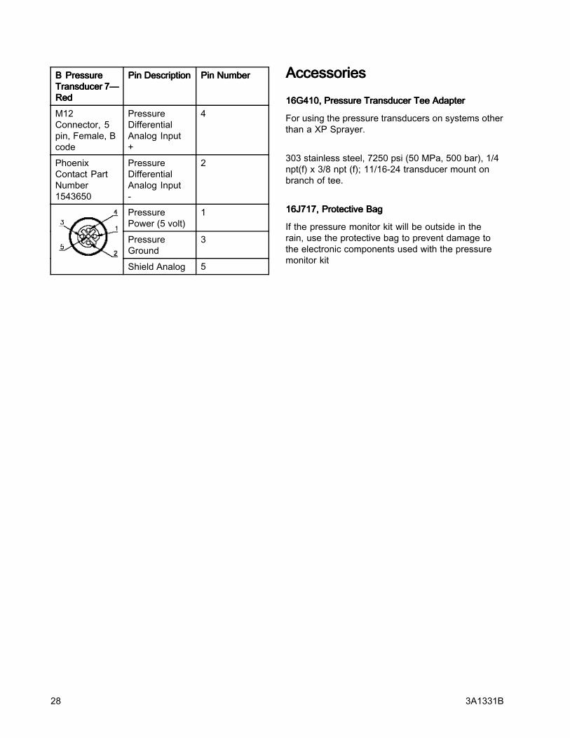
BBB PressurePressurePressureTransducerTransducerTransducer 7—7—7—RedRedRed
PinPinPin DescriptionDescriptionDescription PinPinPin NumberNumberNumber
M12Connector, 5pin, Female, Bcode
PressureDifferentialAnalog Input+
4
PhoenixContact PartNumber1543650
PressureDifferentialAnalog Input-
2
PressurePower (5 volt)
1
PressureGround
3
Shield Analog 5
AccessoriesAccessoriesAccessories
16G410,16G410,16G410, PressurePressurePressure TransducerTransducerTransducer TeeTeeTee AdapterAdapterAdapter
For using the pressure transducers on systems otherthan a XP Sprayer.
303 stainless steel, 7250 psi (50 MPa, 500 bar), 1/4npt(f) x 3/8 npt (f); 11/16-24 transducer mount onbranch of tee.
16J717,16J717,16J717, ProtectiveProtectiveProtective BagBagBag
If the pressure monitor kit will be outside in therain, use the protective bag to prevent damage tothe electronic components used with the pressuremonitor kit
28 3A1331B

TechnicalTechnicalTechnical DataDataData
PressurePressurePressure TransducersTransducersTransducers
Fluid pressure range: 50-7250 psi (3-500 bar)
PowerPowerPower requirementsrequirementsrequirements forforformodelmodelmodel 262940:262940:262940:
Voltage: 90-260 VAC
Frequency: 50-60 Hz
Phase: 1
Amps: 1
CompressedCompressedCompressed airairairrequirementsrequirementsrequirements forforfor modelmodelmodel262942:262942:262942:
Minimum air supplypressure
40 psi (2.75 bar)
Maximum air supplypressure
150 psi (10.3 bar)
Air Consumption 6 scfm
Turbine air pressureset point (pre-set insidebox)
25 psi (1.72 bar)
Certification:Certification:Certification: CE*
* When an Electrostatic Discharge (ESD) is appliedto the display, the screen might clear. Turn the powersupply off and on, or turn the turbine off and on.
3A1331B 29

GracoGracoGraco StandardStandardStandard WarrantyWarrantyWarrantyGraco warrants all equipment referenced in this document which is manufactured by Graco and bearing itsname to be free from defects in material and workmanship on the date of sale to the original purchaser foruse. With the exception of any special, extended, or limited warranty published by Graco, Graco will, for aperiod of twelve months from the date of sale, repair or replace any part of the equipment determinedby Graco to be defective. This warranty applies only when the equipment is installed, operated andmaintained in accordance with Graco’s written recommendations.This warranty does not cover, and Graco shall not be liable for general wear and tear, or any malfunction,damage or wear caused by faulty installation, misapplication, abrasion, corrosion, inadequate or impropermaintenance, negligence, accident, tampering, or substitution of non-Graco component parts. Nor shallGraco be liable for malfunction, damage or wear caused by the incompatibility of Graco equipmentwith structures, accessories, equipment or materials not supplied by Graco, or the improper design,manufacture, installation, operation or maintenance of structures, accessories, equipment or materialsnot supplied by Graco.This warranty is conditioned upon the prepaid return of the equipment claimed to be defective to anauthorized Graco distributor for verification of the claimed defect. If the claimed defect is verified, Gracowill repair or replace free of charge any defective parts. The equipment will be returned to the originalpurchaser transportation prepaid. If inspection of the equipment does not disclose any defect in materialor workmanship, repairs will be made at a reasonable charge, which charges may include the costs ofparts, labor, and transportation.THISTHISTHIS WARRANTYWARRANTYWARRANTY ISISIS EXCLUSIVE,EXCLUSIVE,EXCLUSIVE, ANDANDAND ISISIS INININ LIEULIEULIEU OFOFOF ANYANYANY OTHEROTHEROTHER WARRANTIES,WARRANTIES,WARRANTIES, EXPRESSEXPRESSEXPRESS ORORORIMPLIED,IMPLIED,IMPLIED, INCLUDINGINCLUDINGINCLUDING BUTBUTBUT NOTNOTNOT LIMITEDLIMITEDLIMITED TOTOTO WARRANTYWARRANTYWARRANTY OFOFOF MERCHANTABILITYMERCHANTABILITYMERCHANTABILITY OROROR WARRANTYWARRANTYWARRANTYOFOFOF FITNESSFITNESSFITNESS FORFORFOR AAA PARTICULARPARTICULARPARTICULAR PURPOSE.PURPOSE.PURPOSE.Graco’s sole obligation and buyer’s sole remedy for any breach of warranty shall be as set forth above.The buyer agrees that no other remedy (including, but not limited to, incidental or consequential damagesfor lost profits, lost sales, injury to person or property, or any other incidental or consequential loss) shallbe available. Any action for breach of warranty must be brought within two (2) years of the date of sale.GRACOGRACOGRACO MAKESMAKESMAKES NONONO WARRANTY,WARRANTY,WARRANTY, ANDANDAND DISCLAIMSDISCLAIMSDISCLAIMS ALLALLALL IMPLIEDIMPLIEDIMPLIED WARRANTIESWARRANTIESWARRANTIES OFOFOFMERCHANTABILITYMERCHANTABILITYMERCHANTABILITY ANDANDAND FITNESSFITNESSFITNESS FORFORFOR AAA PARTICULARPARTICULARPARTICULAR PURPOSE,PURPOSE,PURPOSE, INININ CONNECTIONCONNECTIONCONNECTION WITHWITHWITHACCESSORIES,ACCESSORIES,ACCESSORIES, EQUIPMENT,EQUIPMENT,EQUIPMENT, MATERIALSMATERIALSMATERIALS OROROR COMPONENTSCOMPONENTSCOMPONENTS SOLDSOLDSOLD BUTBUTBUT NOTNOTNOT MANUFACTUREDMANUFACTUREDMANUFACTURED BYBYBYGRACO.GRACO.GRACO. These items sold, but not manufactured by Graco (such as electric motors, switches, hose, etc.),are subject to the warranty, if any, of their manufacturer. Graco will provide purchaser with reasonableassistance in making any claim for breach of these warranties.In no event will Graco be liable for indirect, incidental, special or consequential damages resulting fromGraco supplying equipment hereunder, or the furnishing, performance, or use of any products or othergoods sold hereto, whether due to a breach of contract, breach of warranty, the negligence of Graco, orotherwise.FOR GRACO CANADA CUSTOMERSThe Parties acknowledge that they have required that the present document, as well as all documents,notices and legal proceedings entered into, given or instituted pursuant hereto or relating directly orindirectly hereto, be drawn up in English. Les parties reconnaissent avoir convenu que la rédaction duprésente document sera en Anglais, ainsi que tous documents, avis et procédures judiciaires exécutés,donnés ou intentés, à la suite de ou en rapport, directement ou indirectement, avec les procéduresconcernées.
GracoGracoGraco InformationInformationInformationFor the latest information about Graco products, visit www.graco.com.ToToTo placeplaceplace ananan order,order,order, contact your Graco Distributor or call to identify the nearest distributor.Phone:Phone:Phone: 612-623-6921 ororor TollTollToll Free:Free:Free: 1-800-328-0211 Fax:Fax:Fax: 612-378-3505
All written and visual data contained in this document reflects the latest product information available at the time of publication.
Graco reserves the right to make changes at any time without notice.
Original instructions. This manual contains English, MM 3A1331
GracoGracoGraco Headquarters:Headquarters:Headquarters: MinneapolisInternationalInternationalInternational Offices:Offices:Offices: Belgium, China, Japan, Korea
GRACOGRACOGRACO INC.INC.INC. P.O.P.O.P.O. BOXBOXBOX 144114411441 MINNEAPOLIS,MINNEAPOLIS,MINNEAPOLIS, MNMNMN 55440-144155440-144155440-1441
CopyrightCopyrightCopyright 2011,2011,2011, GracoGracoGraco Inc.Inc.Inc. isisis registeredregisteredregistered tototo ISOISOISO 900190019001
Revised 04/2011