xmotion 125/250 owner-manual
TRANSCRIPT

Xmotion 125/250
OWNER-MANUAl
MAINTENANCE HANDBOOK
TAIWAN GOLDEN BEE CO.,LTD.
PDF created with pdfFactory Pro trial version www.pdffactory.com

TABLE OF CONTENT
1. REGULAR INSPECTION
1-1 Delivery Introduction ----------------------------------------------------- 2
1-2 Inspection Before Running --------------------------------------------- 4
1-3 Regular Maintenance Schedule -------------------------------------- 5
1-4 General Inspection -------------------------------------------------------6
1-5 Notes for Inspection ----------------------------------------------------- 7
2. MAINTENANCE INFORMATION
2-1 Specification Sheet ----------------------------------------------------- 8
2-2 Safety Precautions--------------------------------------------------------10
2-3 Special Tools -------------------------------------------------------------- 11
2-4 List of Grease & Oil Adopted ----------------------------------------- 24
2-5 Circuit Drawings --------------------------------------------------------- 25
2-6 Troubleshooting ---------------------------------------------------------- 27
2-7 Tighting Torque of Screws -------------------------------------------- 27
2-8 Troubleshooting ---------------------------------------------------------- 30
3. DESCRIPTION OF PARTS AND COMPONENTS
3-1 Engine ---------------------------------------------------------------------39
3-2 Electric System ---------------------------------------------------------- 126
Q Q Rnrlv 1^1 \J \J UUUjf I \J I
4. DISASSEMBLY REPAIRMENT
4-1 Notice for Disassembly Repairment ----------------------------- 137
4-2 Removal and lnstallation of Engine -------------------------------138
4-3 Removal and Inspection of Electric Items ----------------------- 199
4-4 Removal and Inspection of Body Parts ----------------------------206
4-5 Brake System ----------------------------------------------------------- 214
î
PDF created with pdfFactory Pro trial version www.pdffactory.com
CHAPTER I REGULAR INSPECTION
1-1 Delivery Introduction 1-4 General Inspection
1-2 Inspection Before Running 1-5 Notes for Inspection
1-3 Regular Maintenance Schedule _______________________
1-1 Delivery Introduction
To inform customers of correct methods to use: To practically and correctly
ride a scooter according to the Instruction of Manual and Maintenance
Handbook. Customers should also try in person according to this manual.
1. Starting:
A. Turn the power switch to "ON."
B. Hold the front or rear brake and press the "START" button.
C. If the scooter is not started, release the "START" button and try again after a few
minutes. Each start should be less than five seconds to avoid battery consumption.
Note: This is an AUTO-CHOKE scooter, thus there is no choke lever.
The fuel is controlled only by throttle grip.
The accelerator has to return to its original place when the scooter is not in use.
D. If the scooter can not be started by the "START" button, try the kick starter.
2. Fuel:
Inform customers to refill the fuel to no more than 80% of the tank capacity only.
PDF created with pdfFactory Pro trial version www.pdffactory.com
2 2
1-1 Delivery Introduction 3
. Lubricant Adopted:
A. WARNING : The engine oil must be refilled when the oil warning lamp lights, otherwise the
engine will be burned-out due to insufficient lubrication. Recommended oil : TGB Genuine
EXTRA 4X OIL.
B. Genuine TGB HYPOID GEAR OIL(or SAE85W-140) will be adopted as gear oil to be
changed on a periodical basis. Gear oil and engine oil are different in their nature.
Attention should be paid to avoid mistake when used.
4. Regular Inspection and Maintenance:
Inform customers of the importance of inspection before running and regular inspection.
A. Inspection Before Running: Riders should perform nspection by themselves before
running.
B. Regular Inspection: Regular inspection should be performed after the first month and
the sixth month and every six months afterwards.
5. Description of Warranty System:
Clearly identify the content of warranty in accordance with the warranty paper.
A. Content and term of warranty.
B. Maintenance items not guaranteed.
C. Items should be followed by customers.
Instruct customers to carry the OWNER'S Manual with them when they come for regular
inspection and maintenance. It is because such inspection should be recorded onto the
Manual.
PDF created with pdfFactory Pro trial version www.pdffactory.com
3 3

1-2 Inspection Before Running
Items to be Inspected Before Running by Customers:
ITEM CONTENT GUIDELINE
1. Starter Is the oil volume proper?
1 .Check Oil Warning Lamp to see if the oil volume is proper?
2 .Fuel Is the fuel volume sufficient?
1 .Check fuel volume to see if it is enough to the destination.
3. Lamp & Direction Indicator
Is the lamp condition well? Is there any dirt?
1 .Check if the lighting condition of head lamp, tail lamp, licence lamp, brake lamp, direction indicator and other lamp is well. 2. Lamps should be kept clean and undamaged.
4. Back Mirror Is the reflecting image well?
1. Look at the back mirror from the seat to check if the rear view is clear.
5. License Plate & Reflector
No dirt and damage should appear.
1. License plate should be installed, letters and numbers should be kept clear and clean. 2. Dirt and damage should not appear on the reflector.
6 . Brake Check the distance of brake handle lever and the brake effect.
1 .Operate the handle lever slowly to the brake begin to effect in order to inspect the moving distance. 2.Test the brake with low speed running to see the brake effect of front and rear brakes.
1.Is the air pressure proper?
1 .Check if the air pressure of tire is sufficient with a gauge or by sight.
2.Groove should be deep enough.
1 .Check if the groove of tires is enough.
3.Unusual wear is not desired.
1 .Check landing flat of tire to see if any unusual wear appears.
4.Breaking and damage are not desired.
1 .Check landing flat and side to see if any breaking or damage appear.
7. Tire
5.Metal, stone and other articles are not desired.
1 .Cneck if any cracking, stone or any other article sticks into the tire.
4
PDF created with pdfFactory Pro trial version www.pdffactory.com

1-3 Regular Maintenance Schedule
The chart below lists the recommended intervals for all the returned periodic service work
necessarily to keep the motorcycle operating at peak performance and utmost efficiency.
Mileages are expressed in terms of kilometers and months. These intervals judged by
odometer reading or month whichever comes first.
\~^^^^ Maintenance
N, ^^\ kilometer
300KM Every
1000KM
Every
3000KM
Every
6000KM
Every
12000KM
Item
^^ Maintenance Interval Check Items \
NEW 1 Month 2 Month 3 Month 4 Month
Remarks
01 Air cleaner element(Remark) I C C
02 Oil filter(Screen) C R
03 Engine oil R I Replacement for every 3000KM
04 Tire, pressure I I
05 Battery I I
06 Spark plug I I R
07 Carburetor(idle speed) I I
08 Steering bearing and handles I I
09 Check Transmission for leakage I I
10 Check crankcase for leakage I I
11 Transmission oil R Replacement for every 5000KM
(5 Month)
12 Drive Belt/roller I R
13 Fuel tank switch and lines I I
14 Throttle valve operation and cable I I
15 Engine bolts and nuts I I
16 Cylinder head, cylinder, and piston I
17 Exhaust system/cleaning carbon I
18 Cam chain/ignition time I I
19 Valve clearance I I
20 Shock absorbers I I
21 Front/rear suspension I I
22 Main/side stands I I/L
23 Crankcase Blow - by system(PCV) I I
24 Coolant I I R
25 Cooling fan, lines I I
26 Clutch disk I
27 Brake mechanism/brake lining(pad) I I
28 Bolts/nuts for each components I I
PDF created with pdfFactory Pro trial version www.pdffactory.com
5

*The above maintenance schedule is established by taking the monthy 1000 kilometers as
areference which ever comes first.
Code : I ~ Inspection, cleaning, and adjustment R ~ Replacement
C ~ Cleaning(replaced if necessary) L ~ Lubrication
Remark : 1. Clean or replace the air cleanr element more often whe the scooter is operated on
dusty roads or in the Heavily - polluted environment.
2. Maintenance should be performed more often if the scooter is frequently operated
in high speed and after the scooter has accumulated a higher mileage.
1-4 General Inspection General Inspection and Adjus tment
* means adjustable.
Note: The ignition of this scooter by the use of crank-shaft which is 4 ignitions/revolution.
Special attention should be paid while setting the turning speed of Engine by Tachometer.
Brake Disc
Tail Light/Turn
Signal Light
Gear Oil
Spark Plug
Raer Brake
Brake Disc
PDF created with pdfFactory Pro trial version www.pdffactory.com
Fuses
Head Light
Tire
Air Filter
Head Lig
Tail Light/Turn
Signal Light
Raer
6 6
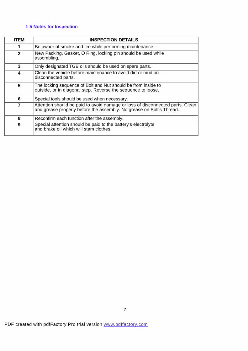
1-5 Notes for Inspection
ITEM INSPECTION DETAILS
1 Be aware of smoke and fire while performing maintenance.
2 New Packing, Gasket, O Ring, locking pin should be used while assembling.
3 Only designated TGB oils should be used on spare parts.
4 Clean the vehicle before maintenance to avoid dirt or mud on disconnected parts.
5 The locking sequence of Bolt and Nut should be from inside to outside, or in diagonal step. Reverse the sequence to loose.
6 Special tools should be used when necessary. 7 Attention should be paid to avoid damage or loss of disconnected parts. Clean
and grease properly before the assembly. No grease on Bolt's Thread.
8 Reconfirm each function after the assembly. 9 Special attention should be paid to the battery's electrolyte
and brake oil which will stam clothes.
7
PDF created with pdfFactory Pro trial version www.pdffactory.com

CHAPTER 2
MAINTENANCE INFORMATION
2-1 Specification Sheet
CU8 (X-Motion 125) Air Filter Paper Type
Length (mm) 2130 Fuel Capacity 11 L
Width (mm) 840 Type CVK164 Dimen
Height (mm) 1380 Venturi (mm) 25
sion
Wheelbase (mm) 1500
Front 55
Fuel
System Carburetion
Rear 95
Unload
mass Total 150
Type C.D.I.
Mas
Front 102 Spark CR8E
Rear 198
Ignition
Pointgap (mm) 0.8+0.1
s
Total mass
2 person/
150 kg Total 300
Electric
system
Battery Type GTX14-BS
Front 120/70-14 type Automatic Tire
Rear 140/60-13 Clutch type Centrifugal type
Engine Type 4 Stroke 4V electroplated
ceramic cylinders engine
Transmission type CVT
Fuel Type Petrol Type Automatic
Number of Cylinder Single cylinder R1 0.79~2.72
Bore X Stroke (mm ) 57 X 48.8
Gear Box
Gear
Ratio R2 9.67
Cylinder Capacity 124.5 c.c.
Transmis -
sion
Starter Electric &Kick raked angle ( ° ) Cooling System Liquid Front 28
Lubrication system Forced circulation & splashing
Tire Pressure (psi)
Rear 32
Reference and setting range(IN ) 0.12±0.02 mm Left Reference and setting range(EX) 0.12±0.02 mm
Motion
system
Turn angel ( ° )
Right ...
MaxSpeed (km/hr) 105 km/h Front Disk
Idle speed (rpm ) 1800+100 rpm
Braking system
Rear Disk
Max Power ( Kw/rpm ) 9 kw/8750 rpm Front Hydraulic-pressed Spring type
Max Torque (Nm/rpm) 10.5Nm/8250rpm
Suspension
Rear Hydraulic-pressed Spring type
Compression Ratio 10.5 Front Hydraulic-pressed Spring
Oil Spec. SAE 10W-30
Buffer
Buffer
Rear Hydraulic-pressed Spring
Oil Capacity ( L ) 1 L Frame Type Welding Tube
Engine
Gear Oil Spec., Capacity SAE 90, 0.11L
Front Lamp 35W/35W-12V
Rear Lamp 5W-12V
Brake Lamp 21W-12V
Lamp
Direction Lamp 21W-12V
8
PDF created with pdfFactory Pro trial version www.pdffactory.com

CUB (X-Motion 250) Air Filter Paper Type
Length (mm) 2130 Fuel Capacity 11 L
Width (mm) 840 Type ...
Height (mm) 1380 Venturi (mm) ...
Dimension
Wheelbase (mm) 1500
Front 60
Fuel
System Carburetion
Rear 100
Unload mass
Total 160
Type E.C.U.
Front 107 Spark CR8E
Rear 203
Ignition
Point ga (mm) 0.8±0.1
Mass
Total mass 2
person/ 150
kg Total 310
Electric
system
Battery Type GTX14-BS
Front 120/70-14 type Automatic Tire
Rear 140/60-13 Clutch type Centrifugal type
Engine Type 4 Stroke Transmission type CVT
Fuel Type Petrol Type Automatic
Number of Cylinder Single cylinder R1 0.8~2.30
Bore X Stroke (mm ) 71 X 63.3
Gear Box
Gear
Ratio R2 7.42
Cylinder Capacity 249.4 c.c.
Transm -
ission
Starter Electric raked angle ( ° ) —
Cooling System Liquid Front 28
Lubrication system Forced circulation &
splashing
Tire Pressure
(psi) Rear 32
Reference and setting
range(IN)
0.1 ±0.02 mm Left —
Reference and setting
range(EX)
0.15±0.02 mm
Motion
system
Turn angel ( ° )
Right —
Max Speed (km/hr) 128 km/h Front Disk
Idle speed (rpm ) 1650±100 rpm
Braking system
Rear Disk
Max Power ( Kw/rpm ) 17.2kw/8750 rpm Front Hydraulic-pressed Spring type
Max Torque (Nm/rpm) 22.7Nm/8250rpm
Suspension
Rear Hydraulic-pressed Spring type
Compression Ratio 10.8 Front Hydraulic-pressed Spring
Oil Spec. SAE 10W-30
Buffer
Buffer
Rear Hydraulic-pressed Spring
Oil Capacity (L) 1.4 L Frame Type Welding Tube
Engine
Gear Oil Spec.,Capacity SAE 90, 0.18L
Front Lamp 35W/35W-12V
Rear Lamp 5W-12V
Brake Lamp 21W-12V
Lamp
Direction Lamp 21W-12V
PDF created with pdfFactory Pro trial version www.pdffactory.com
9 9

2-2 Safety Precautions
Warning: Engine Exhaust
Please keep good ventilation during engine operation. Do not operate engine in closed-room.
The toxic carbon-oxygen (CO) in exhaust may lead human to loss conscious and even death.
Warning: Gasoline
The gasoline is very easy to burn or explode. Forbid any fire during inspection of gasoline
tank or gasoline leak.
Warning: Battery H2 and Battery Liquid
1. The battery liquid is toxic sodium liquid. Please do not contact the liquid with skin or eye. If
any contact happens, please wash with massive clean water and contact with doctor.
2. The released H2 from battery is explosive. Please keep good ventilation during charging
battery and forbid any fire.
Watch: Brake Fluid
The brake fluid can damage the painting on plastic. Please cover the plastic parts with towel
or cloth during maintenance of brake disk. If the brake fluid is split on plastic component,
please remove the fluid and wash the surface with water right away.
Watch: High Temperature of Engine
The engine cover, cylinder, and exhaust pipe have high temperature after starting of engine.
Please wear glove in maintenance of parts during engine operation, or maintenance should
be waited until engine is cooled.
10
PDF created with pdfFactory Pro trial version www.pdffactory.com

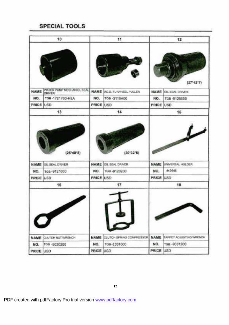
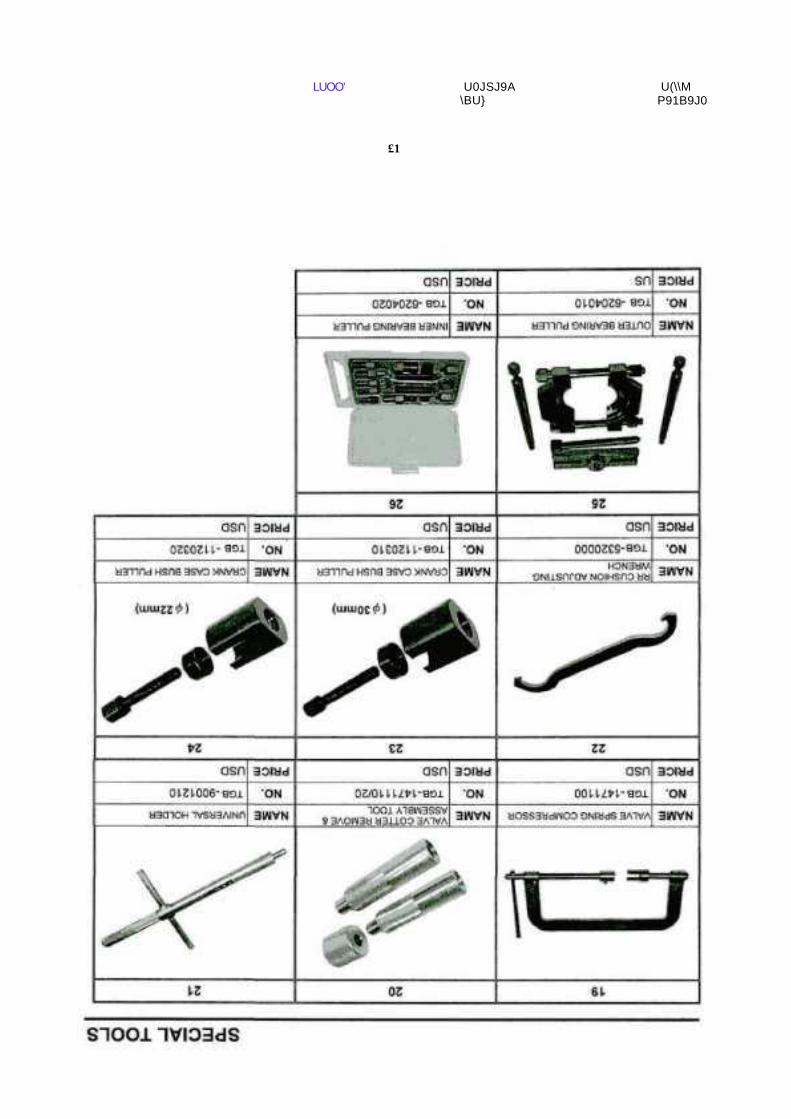
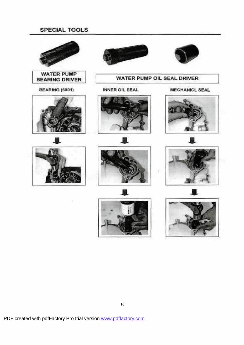
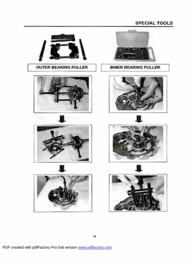
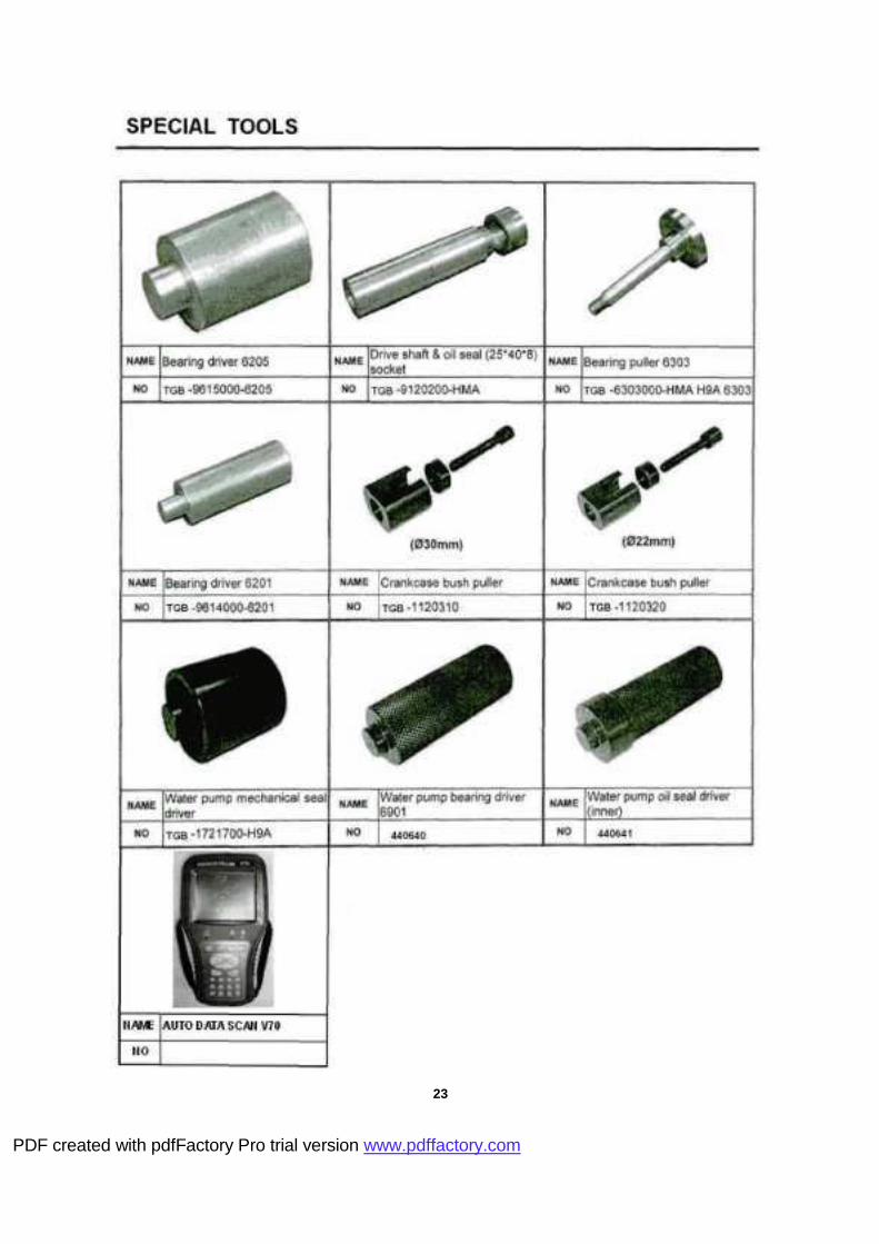
2-3 Special Tools 125 ce:
11
PDF created with pdfFactory Pro trial version www.pdffactory.com
12
PDF created with pdfFactory Pro trial version www.pdffactory.com
LUOO' U0JSJ9A \BU}
U(\\M P91B9J0
£1

14
PDF created with pdfFactory Pro trial version www.pdffactory.com

PDF created with pdfFactory Pro trial version www.pdffactory.com
16
PDF created with pdfFactory Pro trial version www.pdffactory.com

17
PDF created with pdfFactory Pro trial version www.pdffactory.com

18
PDF created with pdfFactory Pro trial version www.pdffactory.com
19
PDF created with pdfFactory Pro trial version www.pdffactory.com

woo■ UOJSJGA \e\j\ ojd Âjopejpd

LUOO■ Ajojoewpa Nwm UOJSJGA \BU} OJd Âjojoejpd I^M

22
PDF created with pdfFactory Pro trial version www.pdffactory.com
23
PDF created with pdfFactory Pro trial version www.pdffactory.com

2-4 List of Grease & Oil Adopted:
TGB Supper Grease No.0 Apply in Oil Seal.
Supper Grease No.3 Apply in Axle Shaft, inside of Oil Seal.
1104 Sealing Three-Bond Apply on Right Hand Crank Surface.
TGB Gear Oil 85w-140 Transmission Gear Oil for Scooters.
TGB Genuine EXTRA 4X OIL Engine Oil Apply in oil tank
Three-Bond 1322 Under M10 Screw (For medium fixing) for Flywheel Magneto.
TGB Supper Grease No. I Apply in Oil Seal.
DOT-3 Brake Oil For Brake.
TGB Supper Grease No.2 Apply in Kick Starter.
TGB Supper Grease No.4 For Movable Drive Face Comp.
Cemedine 575 Apply in Handle Grip
24
PDF created with pdfFactory Pro trial version www.pdffactory.com
"0 D T| O 3 3 0)
Ui
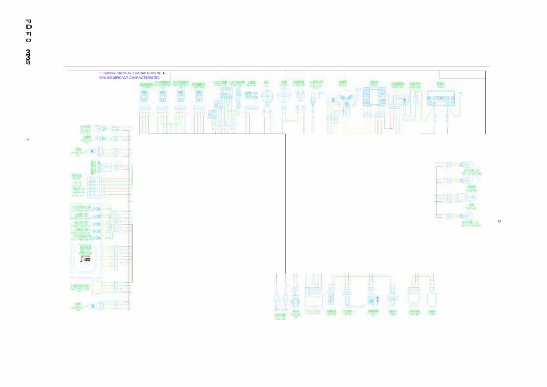
*~t Wfmmk CRITICAL CHARACTERISTIC ► Ifffitt SIGNIFICANT CHARACTERISTEC
—\

O
I
D 3
5
(A
o o
■
u L
1ï "i k r i: k L d )
! 2
COLOR m COLOR COLOR 1 a BLACK r? SÎS CHOCOLATE 28 H/51 WHITE/RED 1- s BLACK 13 ift/
BROWN/WHITE 29 GREEN/BLUE
1- s BLACK 14 M/Ë BLUE/WHITE Jti * PURPLE
2 ii RED 1. »/t GREEN/YELLOW 37 a;/ BLACK/GREEN
2- a RED 16 - GREEN/BLACK 3S a/s BLACK /YELLOW
t-> ,81 RED 1 / w/É YELLOW/WHITE 3U Ë/i. WHITE/BLUE 2- RED ia PINK 4U Ë/w WHITE/YELLOW
2- RED 19 M/ff
BLUE/RED 42 ^/K YELLOW/BLUE
J a RED 2 SKY BLUE 4H SS BLUE
4 s BROW 21 ff/
RED/YELLOW 49 #" ORANGE S) S/Ê GREEN/WHITE
'>■> YELLOW bi BLACK/RED
6 K/w BLUE/YELLOW 2J ,« GREEN b4 YELLOW lu Ë/S WHITE/BLACK 2b BROWN/BLUE bb * YELLOW 11 DEEP GREEN 26 8 1 /
RED/WHITE

"0 D T|
O
3 3 0)
CTN
O o o
C0L0R W COLQR ^^ Hfe COLQR COLQR
1 BLACK 11 3Sg DEEP GREEN 2/ É/i
WHITE/GREEN 4J WHITE/BROW 1- BLACK 12 #î§ CHOCOLATE 2S É/a WHITE/RED 44 YELLOW I-J BLACK 13 BROWN/WHITE 2y ^/M GREEN/YELLOW 4b YELLOW/BLACK RED 14 M/B BLUE/WHITE .1(1 ORANGE/BLUE 4ti GREEN/BROW 2-1 RED 1fi GREEN/YELLOVJ 31 BLUE/ORANGE 4/ ^/* BLACK/PURPLE 2- RED 1
GREEN/BLACK 32 RED/ORANGE 4 BLUE
2- RED 17 #/R YELLOW/WHITE ,1,1 BLUE/GREEN 49 ^g ORANGE
2- RED 1
fôr PINK M ORANGE/WHITE b(
w/^ YELLOW/GREEN RED 1
M/,1
BLUE/RED 3b RED/GRAY b1 BLACK/RED
4 BROW 2 SM SKY BLUE PURPLE b2 SKYBLUE/ORANGE
b iift/É GREEN/WHITE 'A E/w RED/YELLOW 3/ ^/» BLACK/GREEN BROW/YELLOW 6 &/w BLUE/YELLOW 22 M YELLOW 3H ^/w BLACK/YELLOW 7 M/H BLUE/BLACK 23 ,t GREEN jy Ê/M WHI TE/BLUE H H/w BLACK/YELLOW 24 PINK/WHITE 4U &/M WHI TE/YELLOW 9 BROWN/BLACK V. ^/M BROWN/BLUE 41 ilS/fl
GREEN/RED
1U Ê/£ WHI TE/BLACK 2fci SI/B RED /WHI TE 42 f/M YELLQW/BLUE
—ï

2-6 Troubleshooting
Complaint Possible Reason Remedy No action for starter motor 1. Fuse breaks. 2. No power in
battery. 3. Defective action of brake switch. 4 Short circuit of starter relay.
Replace Charging Replace Replace
No sparking or poor sparking 1. Defective spark plug. 2. Defective CDI & ignition coil unit. 3. Defective magneto stator coil. 4. Loose connection of lead wire.
Replace Replace Replace Connect
Unable or Difficult to start
Plug not sparking 1. Damaged spark plug or spark plug cap. 2. Dirty or wet spark plug. 3. Defective CDI &ignition coil unit or stator coil. 4.Open or short in high-tension cord. 5. Defective ignition switch. No fuel reaching the carburetor 1. No gasoline in fuel tank. 2.Clogged hole in the fuel tank cap. 3.Clogged or defective fuel cock. 4.Clogged fuel hose or defective vacuum hose. Compression too low 1. Excessively worn cylinder or piston rings. 2.Spark plug too loose. 3. Broken,cracked or otherwise failed piston.
Replace Clean & dry Replace Replace Replace Replace Clean Clean or replace Clean or replace Replace Tighten Replace
Noisy engine 1 . Piston or cylinder worn down. 2. Combustion chamber fouled with carbon. 3. Piston pin,bearing or piston pin worn. 4. Worn or burnt crankshaft bearings.
Replace Clean Replace Replace
Engine idles poorly 1. Stiff piston ring in place. 2. Excessively worn cylinder or piston rings. 3. Gas leaks from crankshaft oil seal. 4. Defective CDI & ignition coil unit. 5. Clogged jets in carburetor.
Replace Replace Replace Replace Clean or adjust
2-7 Tighting Torque of Screws
*Standard Torque Values of Bolts and Nuts *
Specification Torque (kg-cm) Specification Torque (kg-cm)
5 mm Bolt and Nut 40 8 mm Bolt and Nut 220
5 mm Flange Bolt and Nut 50 8 mm Flange Bolt and Nut 270
6 mm Bolt and Nut 100 10 mm Bolt and Nut 350
6 mm Flange Bolt and Nut 120 10 mm Flange Bolt and Nut 400
6 mm SH Bolt and Nut 90 12 mm Bolt and Nut 550
27
PDF created with pdfFactory Pro trial version www.pdffactory.com

* Torque Values of Chassis Components *
No. Tightening Location Specification Torque
(kg-cm)
1 Front Wheel Axle Self-lock Nut M12 500~600
2 Brake Disk Hex Bolt M5 180~280
3 Brake Clipper Tightening Bolt M 8x35 210~250
4 Speed Meter Cable Nut X 60
5 Front Fork Bearing Tightening Nut M25x1.0 600~650
6 Rear Wheel Axle Self-lock Nut M16x10 600~900
7 Rear Brake Connecting Rod Bolt M16x32 50~80
8 Rear Brake Pin Self-lock Nut M8 250~270
9 Rear Upper Cushion Tightening Bolt M10*46 200~300
10 Rear Lower Cushion Tightening Bolt M8*35 200~300
* Torque Values of Engine components *
Tightening Location Specification Torque Quantities
(kg-cm)
Cylinder Head Bolt M6 80~100 4
Cylinder Stud Bolt M8x182.5 500~800 2
M8x195.5 2
Cylinder Intake Pipe Stud Bolt M6x50 500~800 2
Muffler and Exhaust Pipe Tightening Screw M6 100~120 2
Muffler & Right Crankcase Upper Tightening
Screw
M 8x42 300~400 1
Muffler & Right Crankcase Lower Tightening
Screw
M 8x38 300~400 1
Spark Plug M10 100~120 1
Valve Gap Adjust Lock Bolt M5 50~90 2
Fuel Filter Nut Cap M30 150~200 1
Cooler Fan Lock CR M6x18 500~800 4
Wire Assembly Lock Screw M6x20 800~1000 2
Start Clutch Gear ightening Nut M22 (R.T.) 800~1000 1
Driven Belt Pully Assembly M12 400~600 1
28
PDF created with pdfFactory Pro trial version www.pdffactory.com

Gearbox Cover Tightening Bolt M6x28 100~1200 3
M6x35 3
Gearbox Oil Fill Cover Screw M8 90~150 1
Gearbox Oil Drain Cover Screw M8x12 90~150 1
Clutch Side Cover Screw M6x40 50~80 6
M6x65 2
Starter Arm Tightening Screw M6x22 100~120 1
29
PDF created with pdfFactory Pro trial version www.pdffactory.com

2-8 TROUBLESHOOTING 2-8-1 Troubleshooting for
failure in starting the engine
Analysis of potential causes
Engine does not start
Check if the crank shaft works
See page 19
Does not work works
Check if the starting motor works RPM
Does not work Works Fair Poor (too slow)
Check if the starting gear and the speeding clutch of the starting motor suffer critical wear, if yes,
replace them
Dim light or light off _L Charge the battery or replace it. In case of poor charging, in addition to recharging, check the charging system of the power
plant for failure. 1.
Noise heck the starting
gear and speeding gear of the starting motor for abnormal engagement.
Poor Repair or replace
new buoyant and needle valve
Correct the engagement of the starting motor with the speeding clutch.
a
30
PDF created with pdfFactory Pro trial version www.pdffactory.com
Check battery charging and contact of pins
Loosen the carburetor leakage screw to check for inlet of fuel.
Poor Fair Poor Recharge the battery
and be sure the pin is properly secured.(In case of poor charging, proceed with a new charging and check the charging system of the power plant for failure.)
Check for fuel in the
fuel tank
J:
Check the engine inside (piston, bearing and others) for failure
No fuel I
With fuel Add in
designated fuel
Fair Check fuel tank ventilation tubing for obstruction
Check if the battery is properly charged
_L Bright light Fair
Check the solenoid switch of the starting motor for noise during work
Check for existence of water or other impurities in the carburetor buoyant
Fair No noise
a. Poor contact of starting switch
b. Starting relay breaks or in short circuit
c. Loose contact or wiring
Check for fuel spill in the carburetor
Clean the carburetor and the fuel filter
Check the fuel filter and the tubing
Check skips
in spark Poor
Fair
Clean fuel filter and fuel tubing or replacement
Replacement of new starting motor and check for work.
r
Refer to 1-8-3 No Skip in Spark Plugs for checking
b c

a
1 Poor 1 Check engine pistons, bearings and others
b
Fair
Replace the original starting motor or repair it.
Poor skip
I Fair
Adjustment or replacement of carburetor buoyant needle valve
Check spark plug for cleanliness, normal gap, pollution by gasoline. If yes, check the choke of the carburetor
Fair Poor
Check if the adjustment screws of the carburetor need to be regulated
Clean and adjust spark plug gap or replace with new ones
Poor Fair
Readjustment Check choke of the carburetor for troubles
Fair Poor
_L Check if the slop nozzle of the carburetor is obstructed or the threshold fails
Fair Poor
Test the
compression
Clean or replace the slow nozzle or correct, replace with new threshold
Fair Poor
Check air filter gril for obstruction
Check cylinder washer for leakage, check cylinder, piston, piston ring for wear, with correction, adjustment or replacement
PDF created with pdfFactory Pro trial version www.pdffactory.com
c
Refer to 1-8-2 Poor skip in Spark Plugs for checking
Adjust or replace new choke parts
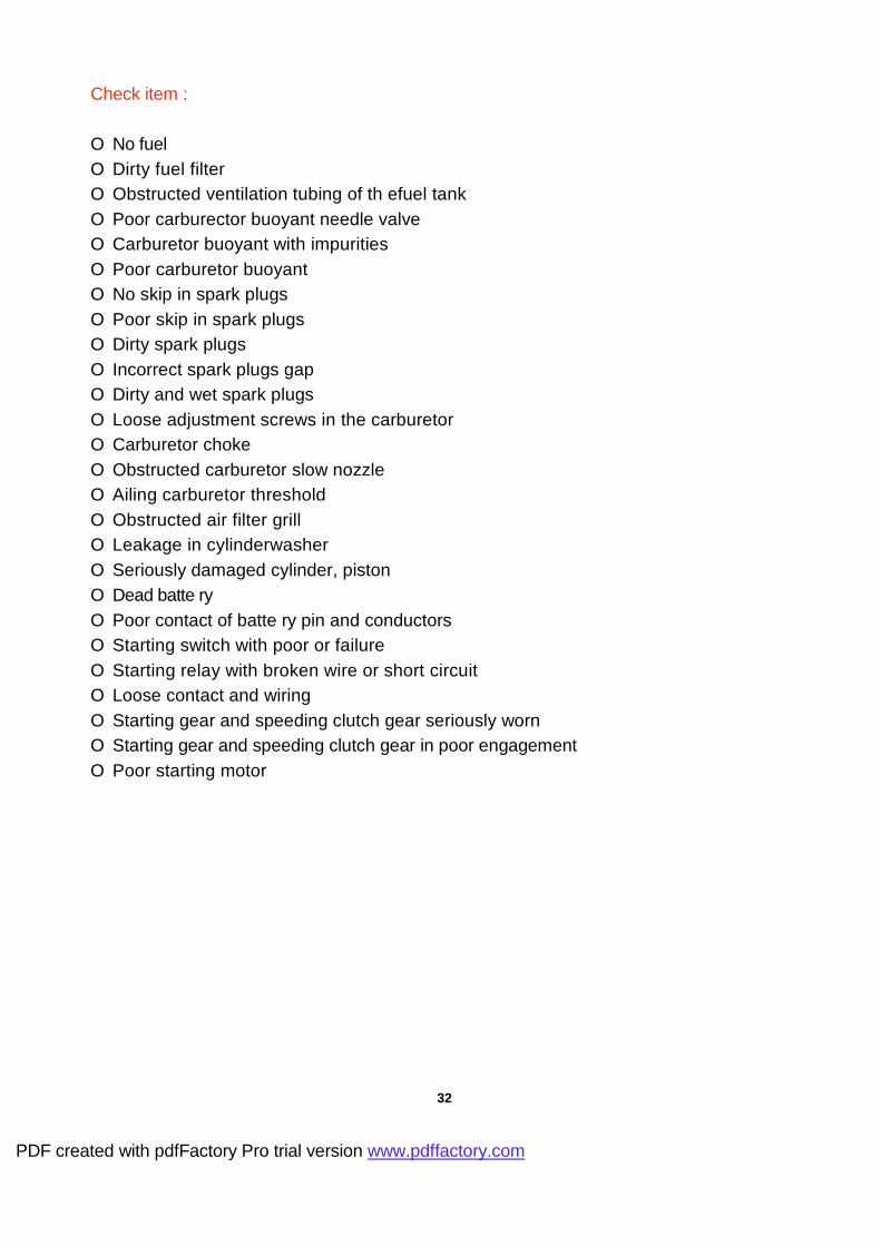
Check item :
O No fuel O Dirty fuel filter O Obstructed ventilation tubing of th efuel tank
O Poor carburector buoyant needle valve
O Carburetor buoyant with impurities
O Poor carburetor buoyant O No skip in spark plugs
O Poor skip in spark plugs
O Dirty spark plugs
O Incorrect spark plugs gap
O Dirty and wet spark plugs
O Loose adjustment screws in the carburetor O Carburetor choke
O Obstructed carburetor slow nozzle
O Ailing carburetor threshold
O Obstructed air filter grill O Leakage in cylinderwasher O Seriously damaged cylinder, piston
O Dead batte ry
O Poor contact of batte ry pin and conductors
O Starting switch with poor or failure
O Starting relay with broken wire or short circuit O Loose contact and wiring
O Starting gear and speeding clutch gear seriously worn
O Starting gear and speeding clutch gear in poor engagement O Poor starting motor
32
PDF created with pdfFactory Pro trial version www.pdffactory.com

2-8-2 Troubleshooting for poor skip of spark plugs
Poor skip of spark plugs Analysis of potential causes
Check for spark plug cap, ignition coil
Normal
Replacement of new spark plug and try skip
again
Loosen spark plugs
Poor spark plugs Poor
high-voltage wiring Poor
distributor coils Poor
PICK Ups Poor main
switches Wiring relay
Poor skip High sparks
Check for loose C.D.I. plugs, terminal conduction and
resistance values
Replacement of poor
spark plug
Abnormal Normal | Poor or abnormal C.D.I. or plugs, replacement of C.D.I. and mount properly the plug
Check high-voltage coils, main switches, PICK UP, distributor coil for normality
Normal ±
Abnormal
Check for correct main wiring contacts and terminals, if necessary, correct them
Poor high-voltage coils, main switches, PICK Ups, distributor coils
33
PDF created with pdfFactory Pro trial version www.pdffactory.com
Loose
Load in the spark plug
cap
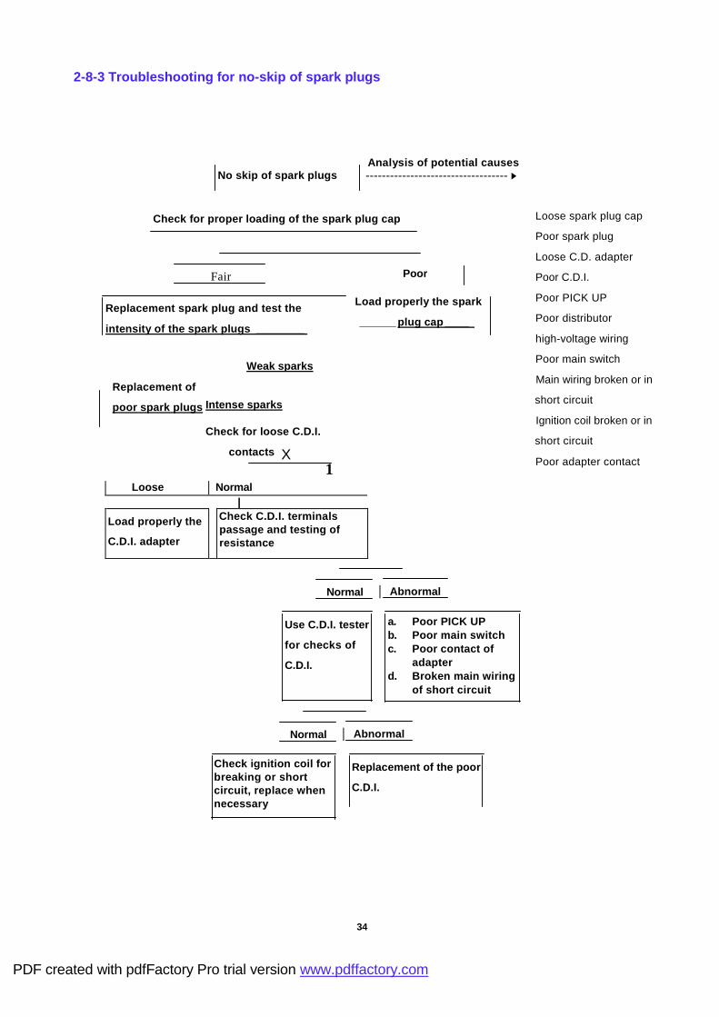
2-8-3 Troubleshooting for no-skip of spark plugs
No skip of spark plugs Analysis of potential causes ----------------------------------- ►
Check for proper loading of the spark plug cap
Fair
Replacement spark plug and test the
intensity of the spark plugs ________
Intense sparks
Check for loose C.D.I.
contacts
1
Loose Normal |
Load properly the
C.D.I. adapter
Check C.D.I. terminals passage and testing of resistance
Loose spark plug cap
Poor spark plug
Loose C.D. adapter
Poor C.D.I.
Poor PICK UP
Poor distributor
high-voltage wiring
Poor main switch
Main wiring broken or in
short circuit
Ignition coil broken or in
short circuit
Poor adapter contact
Normal Abnormal
Use C.D.I. tester
for checks of
C.D.I.
a. Poor PICK UP b. Poor main switch c. Poor contact of
adapter d. Broken main wiring
of short circuit
Normal Abnormal
Check ignition coil for breaking or short circuit, replace when necessary
Replacement of the poor
C.D.I.
34
PDF created with pdfFactory Pro trial version www.pdffactory.com
Load properly the spark
______ plug cap____
Poor
Weak sparks
Replacement of
poor spark plugs
X

2-8-4 Troubleshooting for slow run (troubled engine)
Poor slow run Analysis of potential causes -----------------------------------►
Check for contamination in spark plugs and excessive gap
Poor
Cleaning and
adjustment
Fair
Is the air filter grill
obstructed?
I
Poor Fair |
Replacement of
the filter grill
Is the carburetor buoyant
level normal ?
Fair Poor | |
Check if the choke valve fails (valve does not open) ?
Adjustment or replacement of the buoyant needle valve
Dirty spark plugs
Incorrect spark plug
gaps
Incorrect ignition
timing
Obstructed air filter
grill
Poor carburetor
buoyant needle valve
Poor carburetor choke
valve
Poor engagement of
carburetor and inlet
tube
Obstructed carburetor
slow injection
Poor engagement of
cylinder head washer
Severe wear of
cylinder, piston, piston
ring
Poor Fair
Correction Check of for air between the carburetor and the air inlet
Poor Fair
Add tightening force or replacement of the washer
Check for obstruction in the carburetor slow injection
X
Poor Fair
Cleaning Test the compression
35
Check for air leakage in the cylinder washer, check wear of cylinder, piston, piston ring
and other elements with correction, ______ adjustment or replacement ______
PDF created with pdfFactory Pro trial version www.pdffactory.com
Alarming abnormality of ignition timing
adjustment
Fair
Poor

2-8-5 Poor acceleration and horse power
Poor acceleration and horse power Breakdown of potential causes
-------------------------- ►
Check for drag of braking drum by braking plate
Poor Adjust or replace braking plate
Fair Poor
1
Check for burn of spark
plugs and the gap
Replacement of the
filter grill
1 Poor
Cleaning, adjustment of replacement of new spark plugs
Poor
Test of spark plugs, sparks
• Braking plate retaining braking
drum
• Air filter grill obstructed
• Dirty spark plugs
• Incorrect gap in spark plugs
• Incorrect ignition timing
• Poor skip in spark plugs
• Incorrect adjustment of
carburetor adjustment screw
• Poor choke valve in carburetor
• Dirty or obstructed carburetor
injection nozzle
• Poor carburetor buoyant needle
valve
• Dirty fuel filter
• Obstructed fuel circuitry
• Poor engagement of cylinder
washer
• Serious damage of cylinder,
piston, piston ring
Poor skip
T
Intense sparks
See 2-8-2 poor skip of spark plug for checking methods
Check carburetor for
proper adjustment
X
Poor Fair
Adjustment Check for normal
choke valve action
Poor Fair
Correction or replacement
Check for obstructed
injection nozzle
36
PDF created with pdfFactory Pro trial version www.pdffactory.com
Fair
Check for obstructed air filter t
Fair
Check for normal ignition timing
Fair
Timing
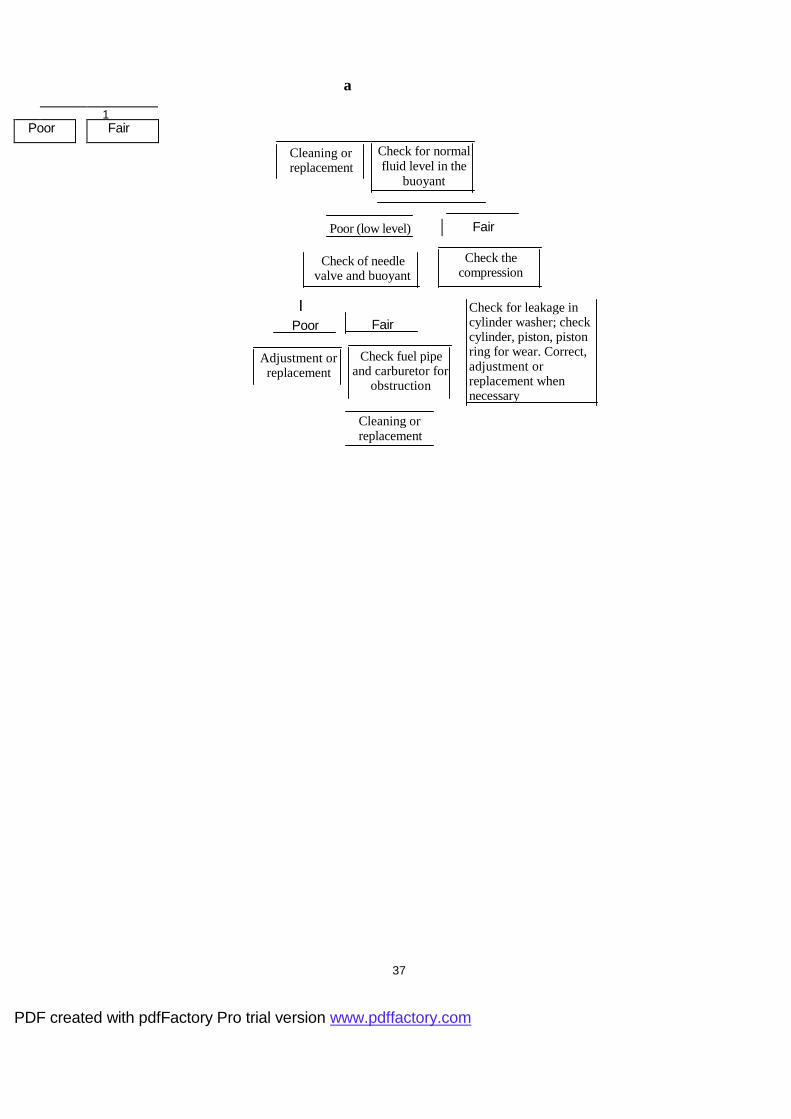
1 Poor Fair
Cleaning or replacement
Check for normal fluid level in the
buoyant
Poor (low level) Fair
Check of needle valve and buoyant
Check the compression
I Poor
Adjustment or replacement
Fair
Check fuel pipe and carburetor for
obstruction
Check for leakage in cylinder washer; check cylinder, piston, piston ring for wear. Correct, adjustment or replacement when necessary
Cleaning or replacement
37
PDF created with pdfFactory Pro trial version www.pdffactory.com
a a

CHAPTER 3 DESCRIPTION OF COMPONENTS AND ASSEMBLY
3-1 ENGINE
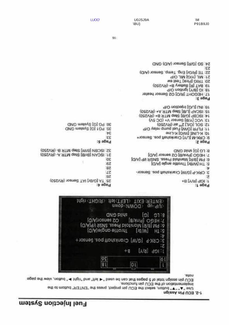
3-1-1 Fuel system (For 125c.c.)
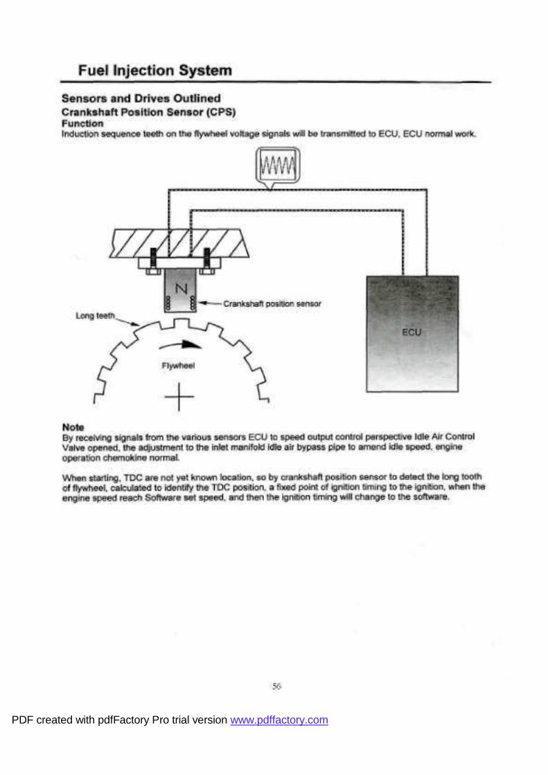
3-1-2 Fuel injection system (For 250c.c.)
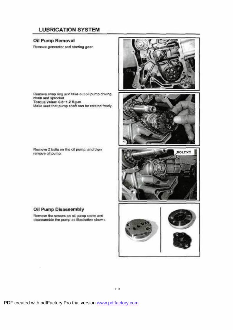
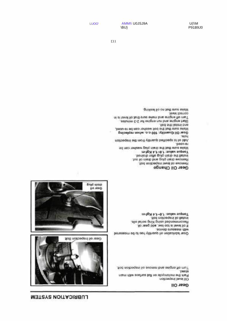
3-1-3 Lubrication System
3-1-4 Cooling System
3-1-5 Spark Plug
3-2 ELECTRIC SYSTEM
3-2-1 Ignition & Charging Device
3.2-2 Lamps
3-3 BODY
3-3-1 Frame & Cover
3-3-2 Compartment and Seat
3-3-3 Front & Rear Suspension System
3-3-4 Brake System
3-3-5 Tire & Tire pressure
38
PDF created with pdfFactory Pro trial version www.pdffactory.com

3-1 ENGINE
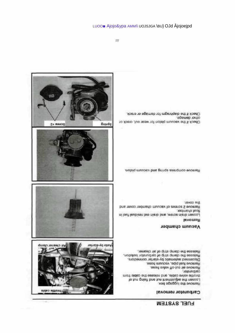
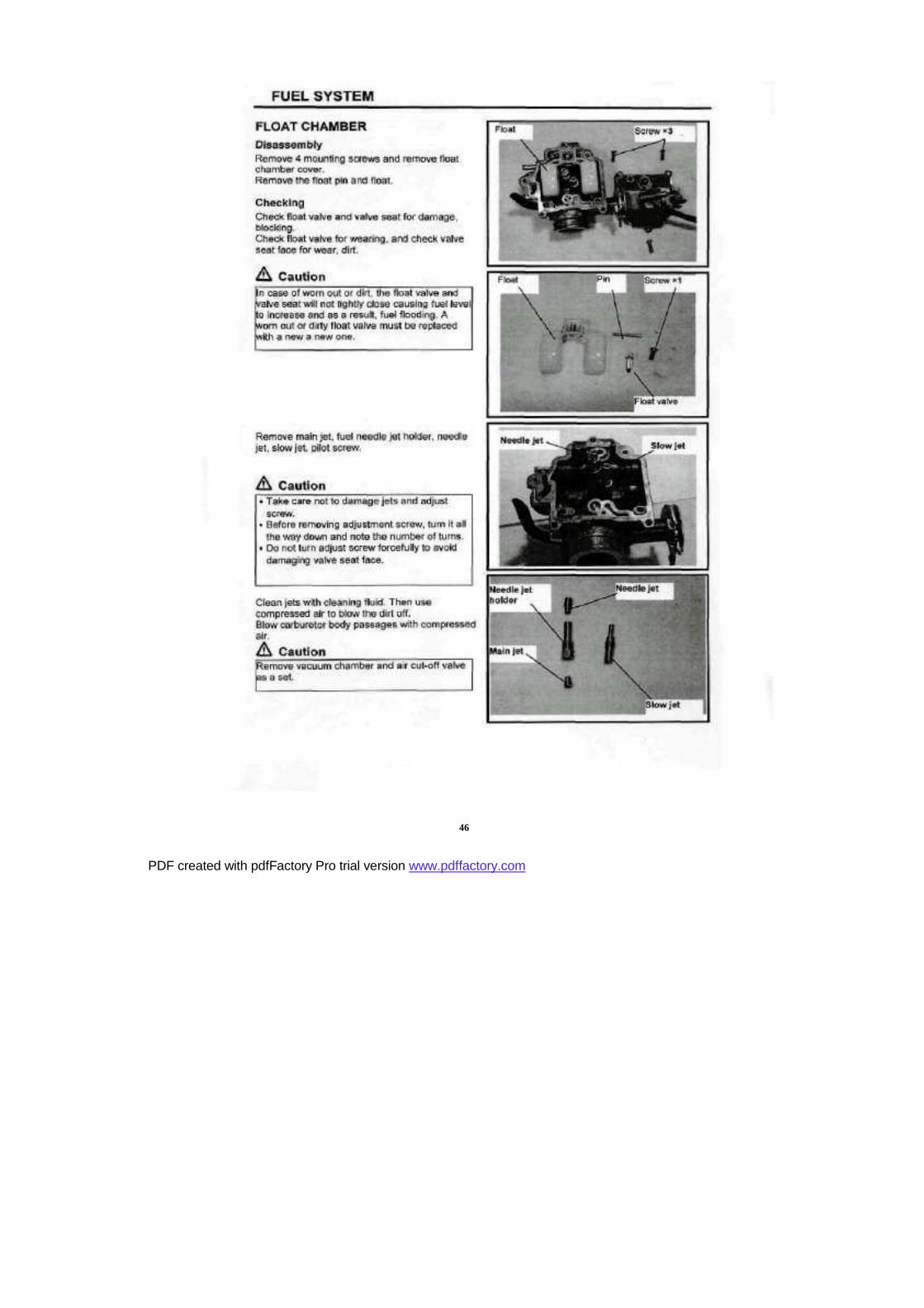
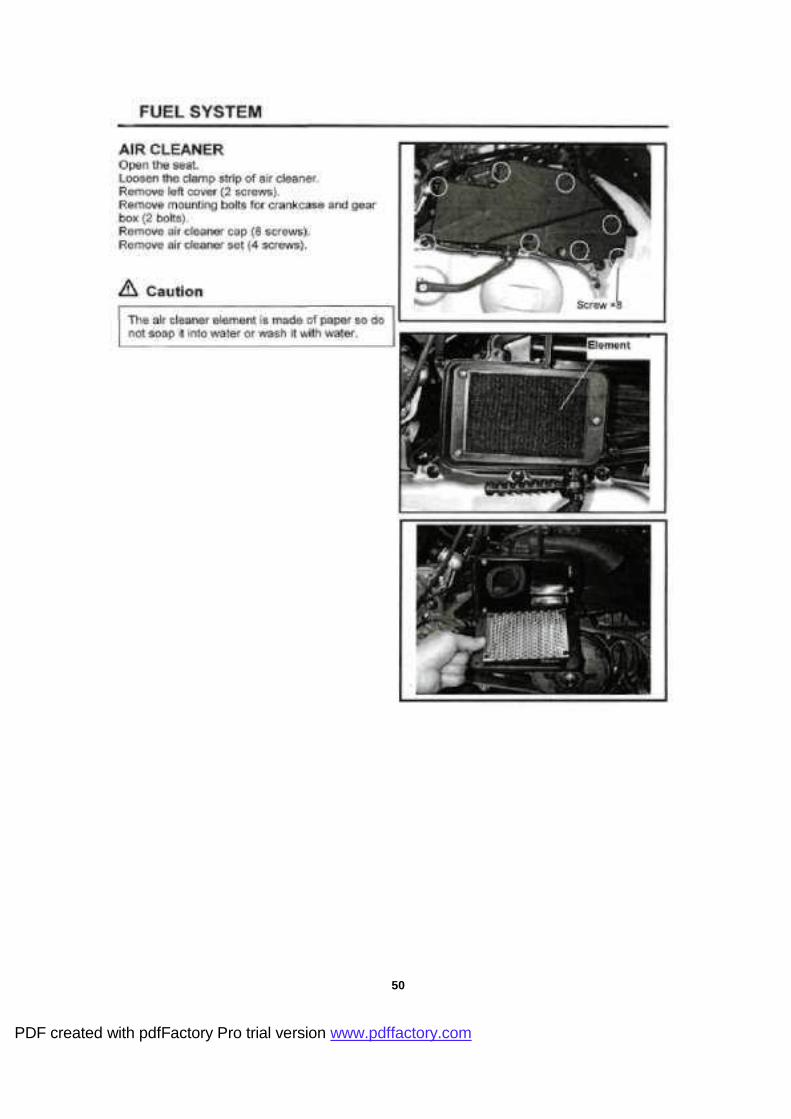
3-1-1 Fuel system (For 125c.c.)
39
PDF created with pdfFactory Pro trial version www.pdffactory.com

PDF created with pdfFactory Pro trial version www.pdffactory.com

41
PDF created with pdfFactory Pro trial version www.pdffactory.com

42
PDF created with pdfFactory Pro trial version www.pdffactory.com

43
PDF created with pdfFactory Pro trial version www.pdffactory.com
LUOO■ Ajojo&ypa AMMI\ UOJSJGA \BU} OJd Âjojoejpd
1717

45
PDF created with pdfFactory Pro trial version www.pdffactory.com
46
PDF created with pdfFactory Pro trial version www.pdffactory.com

LUOO' U0JSJ9A |BU}
U(\\M P91B9J0

48
PDF created with pdfFactory Pro trial version www.pdffactory.com

PDF created with pdfFactory Pro trial version www.pdffactory.com
50
PDF created with pdfFactory Pro trial version www.pdffactory.com

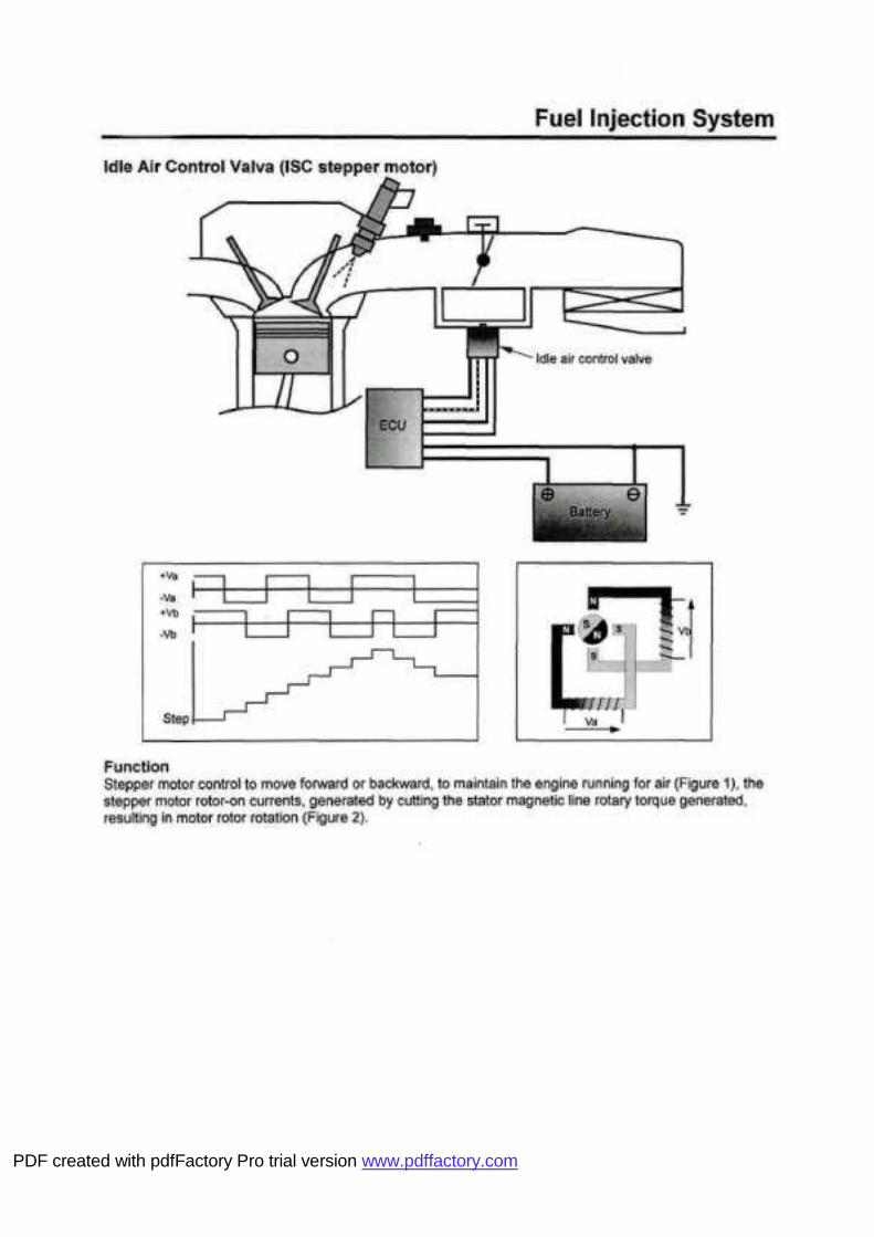
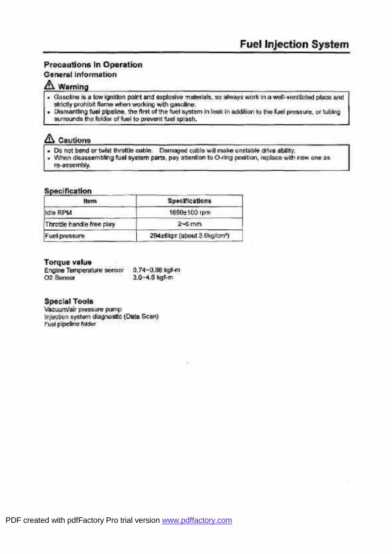
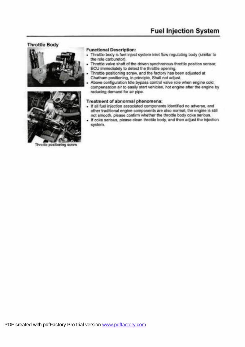
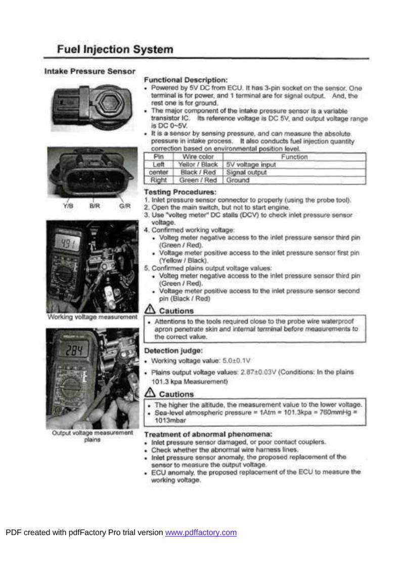
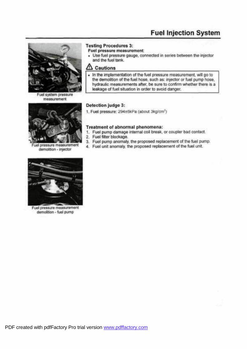
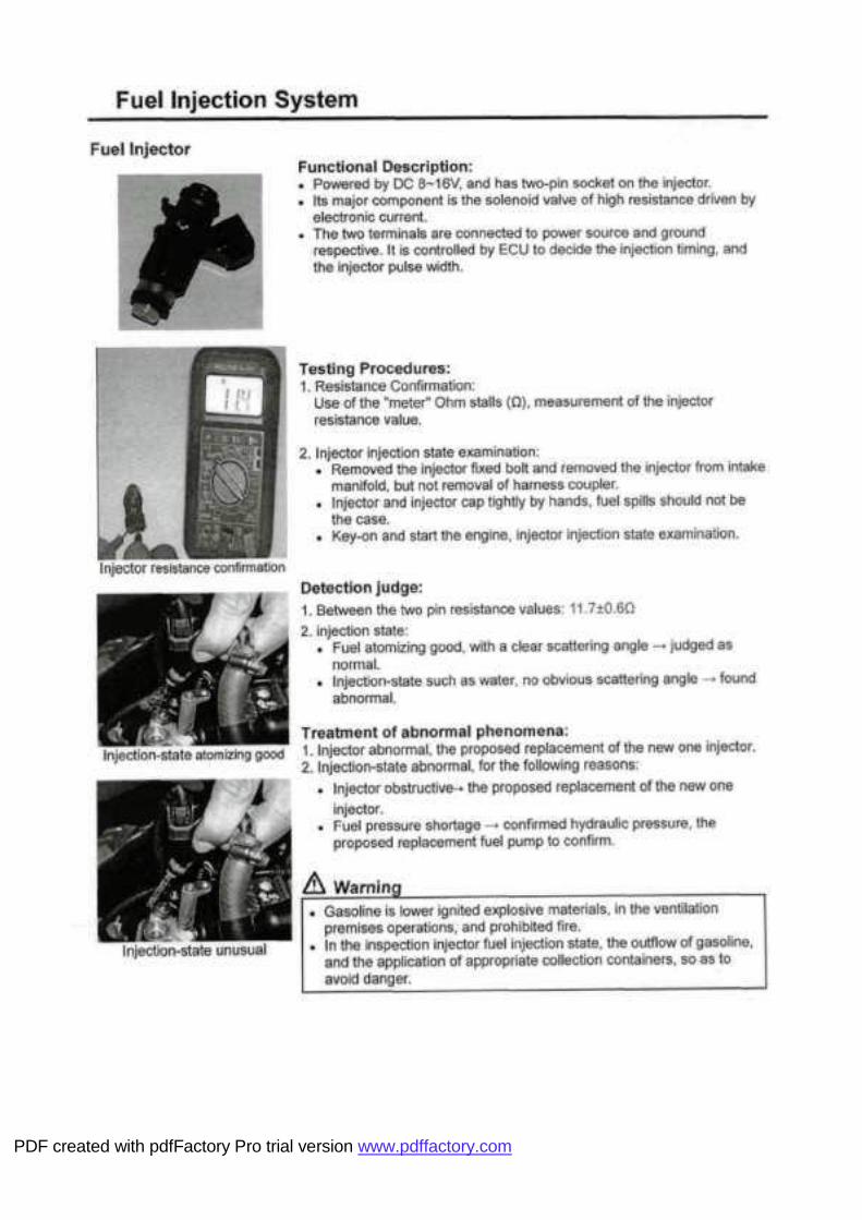
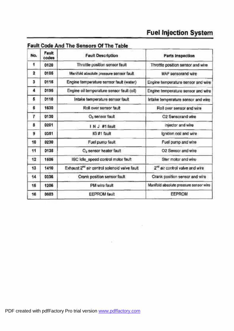
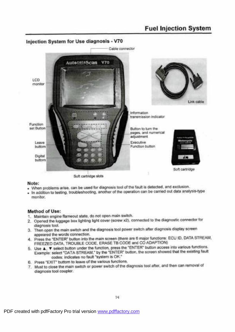
3-1-2 Fuel injection system (For 250c.c.)
PDF created with pdfFactory Pro trial version www.pdffactory.com

PDF created with pdfFactory Pro trial version www.pdffactory.com

PDF created with pdfFactory Pro trial version www.pdffactory.com

PDF created with pdfFactory Pro trial version www.pdffactory.com

PDF created with pdfFactory Pro trial version www.pdffactory.com
PDF created with pdfFactory Pro trial version www.pdffactory.com

PDF created with pdfFactory Pro trial version www.pdffactory.com

PDF created with pdfFactory Pro trial version www.pdffactory.com

PDF created with pdfFactory Pro trial version www.pdffactory.com

PDF created with pdfFactory Pro trial version www.pdffactory.com
PDF created with pdfFactory Pro trial version www.pdffactory.com

PDF created with pdfFactory Pro trial version www.pdffactory.com
PDF created with pdfFactory Pro trial version www.pdffactory.com

LUOO' U0JSJ9A \BU}
P91B9J0
PDF created with pdfFactory Pro trial version www.pdffactory.com
PDF created with pdfFactory Pro trial version www.pdffactory.com

PDF created with pdfFactory Pro trial version www.pdffactory.com

PDF created with pdfFactory Pro trial version www.pdffactory.com

PDF created with pdfFactory Pro trial version www.pdffactory.com

PDF created with pdfFactory Pro trial version www.pdffactory.com

PDF created with pdfFactory Pro trial version www.pdffactory.com

PDF created with pdfFactory Pro trial version www.pdffactory.com

PDF created with pdfFactory Pro trial version www.pdffactory.com

PDF created with pdfFactory Pro trial version www.pdffactory.com
PDF created with pdfFactory Pro trial version www.pdffactory.com
PDF created with pdfFactory Pro trial version www.pdffactory.com

PDF created with pdfFactory Pro trial version www.pdffactory.com

PDF created with pdfFactory Pro trial version www.pdffactory.com

PDF created with pdfFactory Pro trial version www.pdffactory.com

PDF created with pdfFactory Pro trial version www.pdffactory.com

PDF created with pdfFactory Pro trial version www.pdffactory.com

PDF created with pdfFactory Pro trial version www.pdffactory.com

PDF created with pdfFactory Pro trial version www.pdffactory.com

84
PDF created with pdfFactory Pro trial version www.pdffactory.com

PDF created with pdfFactory Pro trial version www.pdffactory.com

PDF created with pdfFactory Pro trial version www.pdffactory.com

PDF created with pdfFactory Pro trial version www.pdffactory.com

PDF created with pdfFactory Pro trial version www.pdffactory.com

PDF created with pdfFactory Pro trial version www.pdffactory.com
PDF created with pdfFactory Pro trial version www.pdffactory.com

PDF created with pdfFactory Pro trial version www.pdffactory.com

PDF created with pdfFactory Pro trial version www.pdffactory.com

PDF created with pdfFactory Pro trial version www.pdffactory.com
PDF created with pdfFactory Pro trial version www.pdffactory.com

PDF created with pdfFactory Pro trial version www.pdffactory.com

96
PDF created with pdfFactory Pro trial version www.pdffactory.com

97
PDF created with pdfFactory Pro trial version www.pdffactory.com
LUOO' U0JSJ9A \BU}
\M P91B9J0

PDF created with pdfFactory Pro trial version www.pdffactory.com

100
PDF created with pdfFactory Pro trial version www.pdffactory.com

101
PDF created with pdfFactory Pro trial version www.pdffactory.com

102
PDF created with pdfFactory Pro trial version www.pdffactory.com

PDF created with pdfFactory Pro trial version www.pdffactory.com

PDF created with pdfFactory Pro trial version www.pdffactory.com
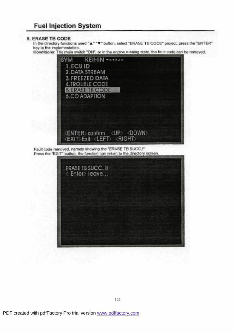
105
PDF created with pdfFactory Pro trial version www.pdffactory.com

PDF created with pdfFactory Pro trial version www.pdffactory.com

LUOO' U0JSJ9A \BU}
\M P91B9J0
LOI
£-\,-£

108
PDF created with pdfFactory Pro trial version www.pdffactory.com

LUOO■ Ajojo&ypa AMMI\ UOJSJGA \eu]
601
110
PDF created with pdfFactory Pro trial version www.pdffactory.com

111
PDF created with pdfFactory Pro trial version www.pdffactory.com

112
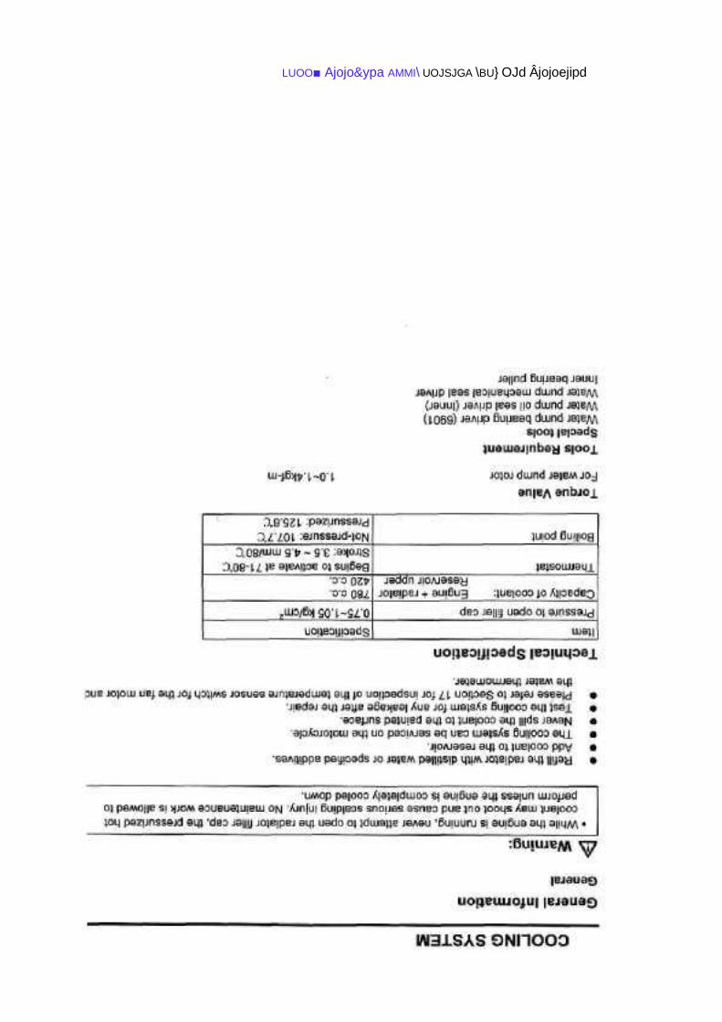
PDF created with pdfFactory Pro trial version www.pdffactory.com
LUOO' AMMI\ U0JSJ9A \BU}
U(\\M P91B9J0
£11

LUOO' AMMI\ U0JSJ9A \BU}
U(\\M P91B9J0
6u||ooo p-i-
LUOO■ Ajojo&ypa AMMI\ UOJSJGA \BU} OJd Âjojoejipd
LUOO' AMMI\ U0JSJ9A |BU}
P91B9J0
911

117
PDF created with pdfFactory Pro trial version www.pdffactory.com

LUOO■ Ajojo&ypa AMMI\ UOJSJGA \eu]
811
LUOO' U0JSJ9A |BU}
U(\\M P91B9J0

LUOO' AMMI\ U0JSJ9A \BU}
U(\\M P91B9J0

LUOO' U0JSJ9A \BU}
P91B9J0
TZI

LUOO' U0JSJ9A |BU}
\J(\\N\ P91B9J0

123
PDF created with pdfFactory Pro trial version www.pdffactory.com

124
PDF created with pdfFactory Pro trial version www.pdffactory.com

125
PDF created with pdfFactory Pro trial version www.pdffactory.com

3-1-5 Spark Plug
Disassemble:
© Spark plug cap.
Note: Please blow away deposits around spark plug with blower before removing spark plug.
Otherwise, the dust may drop into cylinder and it can damage engine.
Inspection: Check if spark plug has carbon deposits, burned, or cracked. Use steel brush to
remove carbon deposits and adjust spark plug gap. Replace burned or cracked spark plug with
new one.
Note: Spark plug specification:
Spark plug gap: 0.6 ~ 0.7 mm. Warning: First
install the spark plug with hand, and then tighten it with
spark plug wrench. Please do not over twist the spark
plug. Note: Torque of spark plug: 100 ~ 120 kg-cm.
3-2 ELECTRIC SYSTEM
3-2-1 Ignition & Charging Device
1. Ignition Device:
CDI Unit of two ignitions per revolution is adopted.
The ignition Lead is 18°±374,000rpm (OLD)
15°±374,000rpm(NEW)
2. Charging Device:
Power is given by flywheel magneto. The voltage is controlled by voltage regulator.
Power is charged to battery.
A. Flywheel Magneto:
Flywheel (rotor) includes four poles, crossed N poles
and S poles. The stator consists of one high-tension
ignition coil and three low-tension coils for charging
and lighting to create change of magnetic field by
rotating the flywheel to generate electricity.
126
PDF created with pdfFactory Pro trial version www.pdffactory.com
B. Battery :
1. Battery Caution:
1. The electrolyte contains sulphuric acid is poisonous. avoid to contact
with eye, skin and clothes. Immediately wash with abundant water
and call a doctor at once in case of contact with the eyes or skin.
Immediately drink beaten eggs or vegetable oil, call a doctor at once
in case of drink.
2. batteries release explosive gases, prohibit to closed to sparks,flames
or cigarettes.
3. When charging or using the battery in a closed location, make sure
that ventilation is good.
4. Keep off children hands.
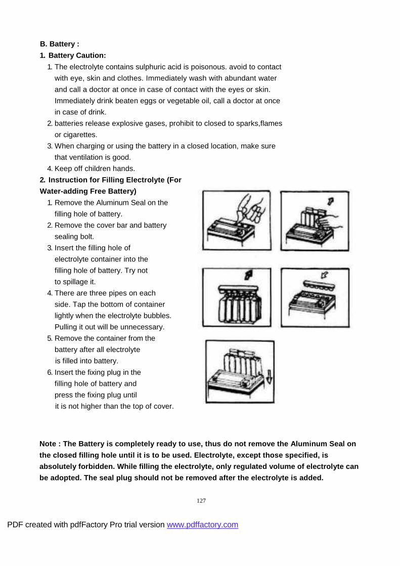
2. Instruction for Filling Electrolyte (For
Water-adding Free Battery)
1. Remove the Aluminum Seal on the
filling hole of battery.
2. Remove the cover bar and battery
sealing bolt.
3. Insert the filling hole of
electrolyte container into the
filling hole of battery. Try not
to spillage it.
4. There are three pipes on each
side. Tap the bottom of container
lightly when the electrolyte bubbles.
Pulling it out will be unnecessary.
5. Remove the container from the
battery after all electrolyte
is filled into battery.
6. Insert the fixing plug in the
filling hole of battery and
press the fixing plug until
it is not higher than the top of cover.
Note : The Battery is completely ready to use, thus do not remove the Aluminum Seal on
the closed filling hole until it is to be used. Ele ctrolyte, except those specified, is
absolutely forbidden. While filling the electrolyte , only regulated volume of electrolyte can
be adopted. The seal plug should not be removed aft er the electrolyte is added.
127
PDF created with pdfFactory Pro trial version www.pdffactory.com

3. THE PROCEDURE OF USING NEW BATTERY
(FOR WATER-ADDING BATTERY )
1. Use the open long plastics tube to instead
of the L-Type closed rubber tube; adjacent
to the " + " pole of the battery.
2. Cut off the tip of the electrolyte's bottle, and
put on the open rubber tube. Take off the
fixing plugs on the battery.
3. Pour the electrolyte into battery carefully to
reach the upper level and the density must
be1.28/20°C..
4. The battery must be stay to decrease the
temperature of the electrolyte to under 35°C. Then begin to charge.
5. Lay the battery for 30 minutes, if battery stay long time, it must recharge again also
according to the table .
Time Within 3 months Afte within above
interval 1 year 1 year
after made
Charging Unnecessary to 3 months 6 months 10 months 40 hours 60 hours
time charge. 10 hours 20 hours 30 hours
Pour electrolyte
into battery.
Lay 30
minutes,then
begin to use.
6. Connect the black lead to the " " pole of battery and red to " + " pole put the battery
to the location and clamp the rubber band.
7. For the connected plastics long tube to the air vent hole of battery , the other end of the tube
must be setted through into the square hole in the plastic leg shield rightly to discharge the
erosive air or sulfuric acid to avoid eroding the body. The tube must be without plugging or
straight bending to avoid exploding.
CAUTION:
It's important to use open long tube to instead of close short
tube to assure normal output of gas to prohibite of exploding.
4. BATTERY MAINTENANCE: (FOR WATER-ADDING BATTERY)
1. Use the same key of main switch to trun right or left 128
PDF created with pdfFactory Pro trial version www.pdffactory.com

to open inner box lid, then disconnect the battery band
and take out the battery, finally take off cable.
2. Checking electrolyte, add distilled water to refill and
adjust to upper level; in case of adding distilled
water frequently, checking the over- charging of the
battery: No voltage indicated on the terminal or no
action on rectifier, means short on the battery, the
voltage will higher than normal, and the life will
shorten.
3. Inspect charged condition:
Add electrolyte to the upper level and check by
battery hyprometer (as attached drawing). The
density of charged battery must be 1.26~1.28
(above 20°C), if the density below 1.2/20°C, it
means fully dis-charged and must be recharged;
The battery must be checked electrolyte level -
density and the voltage after charging.
5. RECHARGING OF THE BATTERY
To Take off the fixing plugs of the battery before charging. Use 1/10 current intensity of the
capacity to recharge the battery about 15-20 hours at normal condition; connect "+" pole of the
battery to "+" pole of the charger, and "—" with "—". CAUTION:
1. Keep the battery away from flames,sparks, and cigarettes.
2. If the temperature of the electrolyte is higher than 45°C, it must to change to half of the
current intensity or stop to charge until decrease to get under 35°C.
3. After charging the battery, adjusting the electrolyte to upper level and recharge 1-2 hours
again,
then put into the fixing plugs, washing and protect with vaseline.
4. Disassemble the "—" pole terminal at first before taking out the battery from scooter, begin
to assemble the "+" pole terminal reversely.
5. If it couldn't reach to 12v, after charging the battery for 15-20 hours, it's necessary to replace
new battery.
6. REGULAR MAINTENANCE OF THE BATTERY
1. Keep the battery clean and dry.
2. Protect the terminals with vaseline.
3. It can reduce the time to 5-6 hours to charge battery at urgent case.
4. Don't use fuse which above standard, otherwise it'll cause broken of scooter or even firing
5. It must to charge before using new battery to keep the maximum
performance, if don't charging adequately or the electrolyte under the low level, it may cause
broken before normal life.
129
PDF created with pdfFactory Pro trial version www.pdffactory.com

6.Tap or drinking water contain mineral will reduce the battery's life, it must to use distilled
water. (For Water- Adding battery)
7.If scooter is stay a long time, it required charged periodically, otherwise it'll fully discharged
by itself above three months.
3-2-2 Lamps
130
PDF created with pdfFactory Pro trial version www.pdffactory.com
Head lamp:
© Remove the bolts of the cover.
© Cover.
© Remove the head lamp couples
Rear lamp:
© Remove the bolts of the cover.
© Cover.
© Remove the rear lamp couples
Inspection: Check if the lamps is damage,
please replace with new one.
Installation:
Install in reverse order of removal procedures.

3-3 BODY
3-3-1 Frame & Cover
1 . Frame :
A. steel pipe and steel sheet are adopted to
compose reinforced frame.
B. A compartment as Personal space for
Helmet is set in the Frame center.
2 . Cover:
1. SEAT SET
2. HELMET CASE
3. BRKT,SEAT
4. CAP, HELMET CASE
5. COVER SIDE,LH. & RH.
6. COVER TAIL,UPPER & UNDER
7. HANDLE,LH. & RH.
8. ORNAMENTAL,HANDLE BAR
9. COVER,HANDLE BAR, UPPER & UNDER
10. WIND SHIELD
11. FRONT,SPEEDOMETER COVER
12. SPEEDOMETER COVER
13. SPEEDOMETER COVER
14. COVER,LEG SHIELD,FRONT
15. LEG SHIELD,FRONT
16. COVER SET,LEG SHIELD
17. FRONT,LUGGAGE BOX
18. LEG SHIELD,REAR
19. COVER RIB,LH. & RH.
20. LEG SHIELD,SIDE LH. & RH.
21. CUSHION,LEG SHIELD,LH. & RH.
22. FRONT FENDER,INNER
23. LEG SHIELD,LOWER
24. FENDER REAR,TANK FUEL
25. FRONT FENDER (FOR CUB) 26. FRONT FENDER,UNDER 27. FRONT FENDER (FOR CUB-B)
131
PDF created with pdfFactory Pro trial version www.pdffactory.com

25
27
132
PDF created with pdfFactory Pro trial version www.pdffactorv.com
19
24

* Dismount floor panels following the sequence shown in the list:
Helmet Case. Mirror, Rear View.
Carrier. Cove Handle Bar,
Upper.
Bottom Plate. Leg Shield Front.
Right and Left Side
Cover.
Front Fender.
Cover Set, Leg Shield Fender, Fixed, Front.
Cover Handle Bar,
Under.
Leg Shield Side,
Lower.
Leg Shield, Rear.
Leg Shield, Lower.
Cautions:
1. Do not damage cover of body panels while dismounting.
2. Handle with care regarding lugs of to avoid damage dismounting.
3. When remounting, do not scratch or crash wiring.
4. While assembling every lug shall be fixated effectively.
5. While assembling, make matching panels and their slots.
133
PDF created with pdfFactory Pro trial version www.pdffactory.com
3-3-2 Compartment and Seat
1 . Compartment:
A. Located in the center of scooter body, there is a Personal Space for helmet and other, etc.
B. The maximum load capacity of compartment is 10kg.
C. Please don't store precious or easy-to-break articles in the compartment without any
protection.
D. The Seat has to be locked. If the Seat is not locked during riding, it will affect the safety
and even cause injury.
E. Please pay attention not to let fuel or oil drop into the compartment.
F. The cover of the compartment can be cleaned with vacuum cleaner.
It can also be washed and put back after dried.
(Please do not wash with volatile fluid, such as ga soline.)
G. The seat is controlled by the seat lock on the side.
2 . Helmet Holder:
There is a Helmet Holder at the position of Seat Hinge.
open the Seat to hook or unhook Helmet.
134
PDF created with pdfFactory Pro trial version www.pdffactory.com

3-3-3 Front & Rear Suspension System
1. Front- Suspension :
A. No suspension on Front Fork.(For B Type)
B. Brake Con-rod and Bracket of Brake Lining
are equipped between Front Fork and
Disc Brake. Resistant Torque occurrs toward
the revolving direction when acting brake. The
Torque will become the force to push Front-
Fork up by using connection Rod. Therefore,
the sink of Front-Fork is stopped and
decreases the change of sitting gesture while
the brake is used.
2 . Rear-Suspension :
A. Suspension Mechanism is 'composed of
single telescopic absorber between the crank
case and scooter body.
B. Rear Axle Movable by telescopic shock
absorber.
3-3-5 Tire & Tire pressure
Inspection: Check if tire has been cracked,
damage, worn, inclusions(stone, nail, glass, etc.).
If tire is in poor condition, please replace with
new one.
Note: Tire specifications: See specification table.
* Tire pressure *
Watch: Please measure cool tire pressure.
Note: Tire pressure.
Front tire: 28 PSI Rear tire: 32 PSI
Warning: Don't over-load the motorcycle.
The tire may explode with over-load and it is dangerous.
135
PDF created with pdfFactory Pro trial version www.pdffactory.com
CHAPTER 4 . DISASSEMBLY REPAIRS
4-1 NOTICE FOR DISASSEMBLY REPAIRS
4-2 REMOVAL AND INSTALLATION OF ENGINE
4-3 REMOVAL AND INSPECTION OF ELECTRIC ITEMS
4-3-1 OPERATING CAUTIOS & TROUBLESHOOTING
4-3-2 BATTERY
4-3-3 SHORT CIRCUIT TEST
4-3-4 STARTER MOTOR
4-3-5 RESISTOR 4-3-6 CDI
4-4 REMOVAL AND INSPECTION OF BODY PARTS 4-4-1
Removal and Inspection of Front Fork and Steering 4 -4-2
Removal and Assembly of Wheel and Shock Absorber
4-5 BRAKING SYSTEM
136
PDF created with pdfFactory Pro trial version www.pdffactory.com
4-1 NOTICE FOR DISASSEMBLY lNSPECTION
1. In order to avoid mixing and loss of disassembled parts before reassembling, the
disassembled parts have to be arranged according to their function during the process.
2. The damage to Cover and Frame should be avoided while disassembling and
assembling.
3. Remove the negative (-) terminal of Battery before working.
4. While reassembling, make sure that all parts are normal.
5. Specified oil should be adopted on turning and sliding parts.
Specified grease should also be applied on specified positions.
6. Dust, dirt and unusual articles should be avoided while reassembling.
7 . While assembling, the main lip of oil seal should face inwards (oil chamber) and the
antidust sub-lip should face outwards.
Apply an even layer of specified grease onto the lip before it is pressed to its location
with balanced force by specified jigs.
8 . While pressing the bearing into the hole, apply balanced force to the outer ring of bearing
by specified jigs.
While pressing the bearing into the main shaft, apply balanced force to the inner ring of
bearing by specified jigs.
137
PDF created with pdfFactory Pro trial version www.pdffactory.com

4-2 REMOVAL AND INSTALLATION OF ENGINE
Removal of Engine:
© Remove Seat and Cover.
© Remove Exhaust Muffler.
© Remove Clamp of Air Filter and Air Filter.
138
PDF created with pdfFactory Pro trial version www.pdffactory.com

© Remove Mud Guard.
© Remove Ignition Coil Lead. Flywheel Magneto Lead. Engine Earth Ground Lead.
© Remove the Throttle Cable,
on Carburetor Piston.
© Remove Oil Hose.
© Remove Negative Pressure Hose and
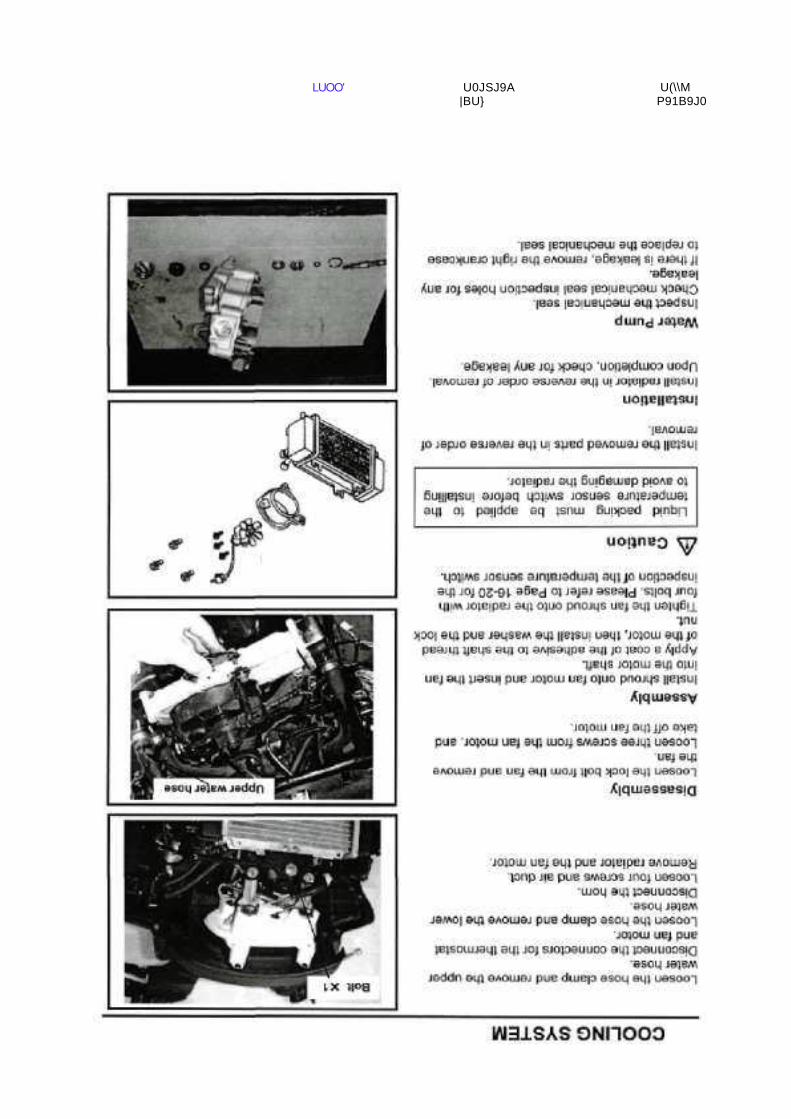
Remove rear belt cooling duct. Remove Fuel Hose.
© Remove Water Hose.
© Remove the engine mounting bolts and nuts.
139
PDF created with pdfFactory Pro trial version www.pdffactory.com

® Remove the rear-axle shaft bolts and remove rear wheel.
©Installation
Install in reverse order of removal procedures.
140
PDF created with pdfFactory Pro trial version www.pdffactory.com
PDF created with pdfFactory Pro trial version www.pdffactory.com

142
PDF created with pdfFactory Pro trial version www.pdffactory.com

143
PDF created with pdfFactory Pro trial version www.pdffactory.com
PDF created with pdfFactory Pro trial version www.pdffactory.com

PDF created with pdfFactory Pro trial version www.pdffactory.com

PDF created with pdfFactory Pro trial version www.pdffactory.com
PDF created with pdfFactory Pro trial version www.pdffactory.com

PDF created with pdfFactory Pro trial version www.pdffactory.com

PDF created with pdfFactory Pro trial version www.pdffactory.com
LUOO■ U0JSJ9A |BU}
U(\\M
OCT

151
PDF created with pdfFactory Pro trial version www.pdffactory.com
PDF created with pdfFactory Pro trial version www.pdffactory.com

PDF created with pdfFactory Pro trial version www.pdffactory.com

PDF created with pdfFactory Pro trial version www.pdffactory com

PDF created with pdfFactory Pro trial version www.pdffactory.com

PDF created with pdfFactory Pro trial version www.pdffactory.com

157
PDF created with pdfFactory Pro trial version www.pdffactory.com

158
PDF created with pdfFactory Pro trial version www.pdffactory.com

LUOO U0JSJ9A |BU}
U(\\M

160
PDF created with pdfFactory Pro trial version www.pdffactory.com

PDF created with pdfFactory Pro trial version www.pdffactory.com

162
PDF created with pdfFactory Pro trial version www.pdffactory.com

PDF created with pdfFactory Pro trial version www.pdffactory.com
PDF created with pdfFactory Pro trial version www.pdffactory.com

LUOO' U0JSJ9A |BU}
U(\\M P91B9J0

PDF created with pdfFactory Pro trial version www.pdffactory.com

PDF created with pdfFactory Pro trial version www.pdffactory.com

LUOO■ Ajojoewpa NMM UOJSJGA IBUI OJd Âjojoejpd I^M
891

169
PDF created with pdfFactory Pro trial version www.pdffactory.com

PDF created with pdfFactory Pro trial version www.pdffactory.com

LUOO' U0JSJ9A |BU}
U(\\N\ P91B9J0

PDF created with pdfFactory Pro trial version www.pdffactory.com

173
PDF created with pdfFactory Pro trial version www.pdffactory.com

PDF created with pdfFactory Pro trial version www.pdffactory.com

PDF created with pdfFactory Pro trial version www.pdffactory.com

LUOO' U0JSJ9A \BU}
P91B9J0
PDF created with pdfFactory Pro trial version www.pdffactory.com

PDF created with pdfFactory Pro trial version www.pdffactory.com

PDF created with pdfFactory Pro trial version www.pdffactory.com

PDF created with pdfFactory Pro trial version www.pdffactory.com

181
PDF created with pdfFactory Pro trial version www.pdffactory.com

PDF created with pdfFactory Pro trial version www.pdffactory.com

LUOO' U0JSJ9A |BU}
\M P91B9J0

PDF created with pdfFactory Pro trial version www.pdffactory.com

185
PDF created with pdfFactory Pro trial version www.pdffactory.com
PDF created with pdfFactory Pro trial version www.pdffactory.com
PDF created with pdfFactory Pro trial version www.pdffactory.com

PDF created with pdfFactory Pro trial version www.pdffactory.com

PDF created with pdfFactory Pro trial version www.pdffactory.com

PDF created with pdfFactory Pro trial version www.pdffactory.com

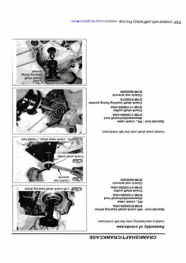
CRANKSHAFT/CRANKCASE
Gênerai information Crankshaft Trouble diaqnosis Assembly of crankcase
Disassemblv of crankcase
PDF created with pdfFactory Pro trial version www.pdffactorv.com
1.2-1.6 kgf -m
1.0-1.5 kgf -m
1.5-3,0 kgf -m O.B-1,2 kgf -m

192
PDF created with pdfFactory Pro trial version www.pdffactory.com

PDF created with pdfFactory Pro trial version www.pdffactory.com

PDF created with pdfFactory Pro trial version www.pdffactory.com

PDF created with pdfFactory Pro trial version www.pdffactory.com
woo■ AJopB^pa ftmm UOJSJGA

PDF created with pdfFactory Pro trial version www.pdffactory.com

LUOO■ NWM UOJSJGA \B\J\ ojd Âjopejpd

4-3 REMOVAL AND INSPECTION OF ELECTRIC ITEMS 4-
3-1 Operating Cautions & Troubleshooting
Operating Cautions:
1. Warning:
a. The liquid in the battery is diluted sulfuric acid that is dangerous. If, your skin or eye
unfortunately get contact with it, please wash with water abundantly and consult
immediately a doctor, lest you should lose vision.
b. If your clothes is touched by the electrolyte, your skin would also be touched.
Therefore you should get it off and wash with water abundantly.
2. Check if electrolyte in the battery is sufficient. If not, add distilled water till the liquid level
reach the upper limit line.
3.The battery is rechargeable after discharging. If it is unused after discharge, it may
deteriorate and shorten service life. It will become less efficient. After usage of 2~3 years,
battery capacity will decrease. It can be regained by recharging several times.
4. When there is other loads while igniting, if the voltage will rise again after an abrupt falling,
it is normal.
5.If a battery is unused during a long time, its energy storage will decrease by its auto-
discharge. Therefore, a recharging is necessary around every 3 months.
6.To charge a battery, it shall be removed from the car and its filler plugs removed. To put the
charging current 'ON' or 'OFF', you must operate at the charger's switch. You shall not
connect or pull off directly on the battery because electric spark may provoke hydrogen
explosion.
7.During battery charging, hydrogen (H2) is produced. It is an inflammable gas. Fire must be
forbidden. 8. At recharging a battery, the temperature of electrolyte shall be lower
than 45°C.
9.To test if a battery is fully charged, please use a voltmeter. Never use 'Spark method'.
10.When there is current in an electrical installation, please do not pull off a contact then
connect it again, because resulting over voltage may damage electronic parts in the
commuter. Therefore, this operation must be done after the main switch is put "OFF".
199
PDF created with pdfFactory Pro trial version www.pdffactory. com

11 .If fresh electrolyte is poured in a new battery, a voltage will be generated after a certain
lapse of time. If the voltage is not sufficient, then a recharging is necessary. A recharged
new battery has necessarily a longer lifetime.
12.The C.D.I of the ignition system shall not fall swinging and be shocked. It is a cause of
frequent breakdown. Therefore, a special precaution is necessary in its dismounting and
remounting.
13.Bad contact between plug and jack causes often the breakdown of the ignition system.
Therefore, before undertaking repair, the contact is to be checked at first.
14.Spark plugs of a suitable heat value and gap are to be used. Otherwise, engine will not
work smoothly or break.
Troubleshooting: Battery Recharging System: No
voltage:
1. Battery cable fallen or disconnected.
2. Fuse fused.
3. Defective of flywheel magneto.
4. Excessive battery discharging:
a. Electrolyte leaked.
b. Chemical reaction in battery.
c. Short circuit in battery.
d. Defective rectifier.
Low voltage:
1. Insufficient recharging.
2. Leaking of electrolyte.
3. Defective separator causing short circuit between positive and negative plates.
1. Defective battery terminals.
2. Defective recharging system.
3. Defective rectifier.
Excessive specific weight of electrolyte:
1. Insufficient recharging.
2. Leaking of electrolyte.
3. Reaction between sulfuric acid and pole plates.
200
PDF created with pdfFactory Pro trial version www.pdffactory.com

Too low capacity:
1. Insufficient recharging.
2. Pole plates react with sulfuric acid.
3. Insufficient electrolyte.
4. Active matter fallen from pole plates because of excessive recharging.
Inefficient recharging system:
1. Bad contact at connectors, short circuitry, or broken circuit.
2. Defective rectifier.
3. Defective of flywheel magneto.
a. Armature winding short circuited or broken.
b. Magneto coil short circuited or broken.
Bad electric continuity:
1. Bad contact at battery connection.
2. Ignition system short circuit or bad contact at connectors.
3. Lighting system short circuit or bad contact at connections.
Ignition System: Dysfunctioning
of spark plugs:
1. Defective of flywheel magneto.
2. Defective high-tension coil.
3. Defective C.D.I .
4. Defective spark plugs.
5. Defective conductor contact, breaking, or short circuit, for example:
a. Conduction between flywheel magneto and C.D.I .
b. Conduction between C.D.I and the main switch.
c. Conduction between C.D.I and the high-tension coil.
Engine not running smoothly:
1. Defective ignition first circuit:
a. Bad contact in circuitry or cable.
b. Defective of flywheel magneto.
2. Bad ignition secondary circuit.
(1) The ignition coil insulation defect causing electric leakage.
(2) Defective magneto coil.
I. Short circuit between coil layers.
II. Defective coil.
201
PDF created with pdfFactory Pro trial version www.pdffactory.com

c. Defective spark plug.
I. Spark plug covered by carbon.
II. Electric leakage in ceramic part of spark plug.
d. Electric leakage from spark plug rubber screen.
3. Defective ignition timing.
a. Defective flywheel magneto.
b. Defective C.D.I .
c. Too large gap of spark plug.
d. Too high electric resistance of spark plug.
Starter System
Starter motor unable to run.
1. Damaged battery.
2. Battery circuit broken, bad contact or too large resistance at connections.
3. Fuse fused.
4. Defective main switch.
5. Defective front and rear brake switches.
6. Defective starter motor switch.
7. Defective starter motor relay.
8. Defective starter motor.
9. Circuitry conductor defective or broken.
10. Starter motor drive pinion locked with the over speed clutch gear.
Weak drive of starter motor:
1. Insufficient recharging of battery.
2. Bad contact on circuit conductors.
3. Strange object introduced in the starter motor pinion.
4. Armature shaft bent.
5. Commutator unclean or worn.
6. Brush worn or spring too weak.
7. Starting motor of relay defective.
202
PDF created with pdfFactory Pro trial version www.pdffactory.com

4-3-2 BATTERY
A. Cautions in battery inspection and generator charging. Inspection: Use gravity gauge to measure electrolyte. White is fully charged, yellow means charge is required, and red is broken or almost totally discharged. Note: Electrolyte's specific gravity and charge level comparison table (20°C).
Electrolyte
Specific Gravity
1.280 1.250 1.220 1.190 1.120
Charge Level Full 3/4
Charged
1/2
Charged
1/4
Charged
Totally
Discharg
B. Charge by generator Connecting battery and gener terminals by "+" with "+" and "-"
with "-". Warning: Battery releases explosive gas during charging or use
battery. Therefore, it is dangerous to do so in concealed location. Please put
battery in good ventilation location during charging, and forbid fire. Note:(1)
Standard charging current: 0.6 A for 5~10 hours.
(2) Quick charging current: 6.0 A for 30 minutes.
(3) Please do not use quick charge except for emergency.
(4) Measure the battery voltage 30 minutes after battery is charged.
The battery voltage should be higher than 12.8 V.
C. Battery manufactured month and charge time comparison.
Manufactue
Months
Within 3
mo.
After 3
mo.
6 mo. 10 mo. Within 1
yr.
Over 1
yr.
Charge
Time
Add electrolyte
And wait 30 m.
10
hr.
20
hr .
30 hr
.
40
hr .
60
hr .
4-3-3 SHORT CIRCUIT TEST
Disassembly:
Disconnect battery negative terminal cable. ■ Measure method: A.
Connect megga meter "+" terminal to battery "-" terminal. 203
PDF created with pdfFactory Pro trial version www.pdffactory.com
B. Connect megga meter "-" terminal to circuit negative cable.
Note: User megga meter "A" current position. ■ Turn main switch
to "OFF" position. Inspection: Check if there is electrical current.
If no current, check the main switch and wire harness for short
circuit.
4-3-4 STARTER MOTOR
(1) Please place main stand to park the
motorcycle for inspection.
(2) Turn the main switch to "OFF" position before maintenance.
Disconnect the battery ground circuit.
To ensure safety, turn the main switch to "ON" position and
check if the motor has operated.
Disassembly:
© Remove starter motor cable. © 2 starter
motor attaching screws. © 2 motor case
attaching bolts. © Starter motor.
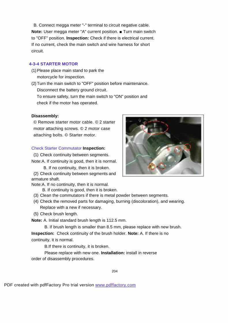
Check Starter Commutator Inspection:
(1) Check continuity between segments.
Note:A. If continuity is good, then it is normal.
B. If no continuity, then it is broken. (2) Check continuity between segments and
armature shaft. Note:A. If no continuity, then it is normal.
B. If continuity is good, then it is broken. (3) Clean the commutators if there is metal powder between segments. (4) Check the removed parts for damaging, burning (discoloration), and wearing.
Replace with a new if necessary.
(5) Check brush length.
Note: A. Initial standard brush length is 112.5 mm.
B. If brush length is smaller than 8.5 mm, please replace with new brush.
Inspection: Check continuity of the brush holder. Note: A. If there is no
continuity, it is normal.
B.If there is continuity, it is broken.
Please replace with new one. Installation: install in reverse order of disassembly procedures.
204
PDF created with pdfFactory Pro trial version www.pdffactory.com

4-3-5 RESISTOR Disassembly: Remove front windshield cover. Measure: A. Use megga meter's positive terminal to connect resistor wire. B. Connect the megga meter's negative terminal with frame ground and measure the resistance. Note: Resistor standard:
20 W 5.9 Ohm: 5.0~7.0 Ohm. 5W 5.0 Ohm: 4.0~6.0 Ohm.
4-3-6 CDI
Use megga meter to check the following items. A. Exciting Coil Inspection Disassembly: The exciting coil connector. Measure: A. Use megga meter's positive terminal to connec t exciting coil's black/red terminal. B. Connect the megga meter's negative terminal with frame ground and measure the resistance.
B. Pulse Coil Inspection Disassembly: The pulse coil connector. Measure: A. Use megga meter's positive terminal to connect pulse coil's blue/yellow terminal. B. Connect the megga meter's negative terminal with body ground and measure the
resistance.
205
PDF created with pdfFactory Pro trial version www.pdffactory.com

4-4 Removal and Installation of body 4-
4-1 Removal and Installation of Seat
and Cover
Seat:
© Remove the nuts and pin.
© Seat.
© Remove 6 bolts on the helmet case.
© Helmet case.
Note:
There is a coupler under the helmet case.
And remove it.
Additions of side cover:
© Remove the handles.
© Remove the bolts on the side cover.
Leg shield:
© Remove the bolts on the leg shield.
(each side) © leg shield.
Installation:
Install in reverse order of removal procedures.
206
PDF created with pdfFactory Pro trial version www.pdffactory.com
Installation:
Install in reverse order of removal procedures.
207
PDF created with pdfFactory Pro trial version www.pdffactory.com
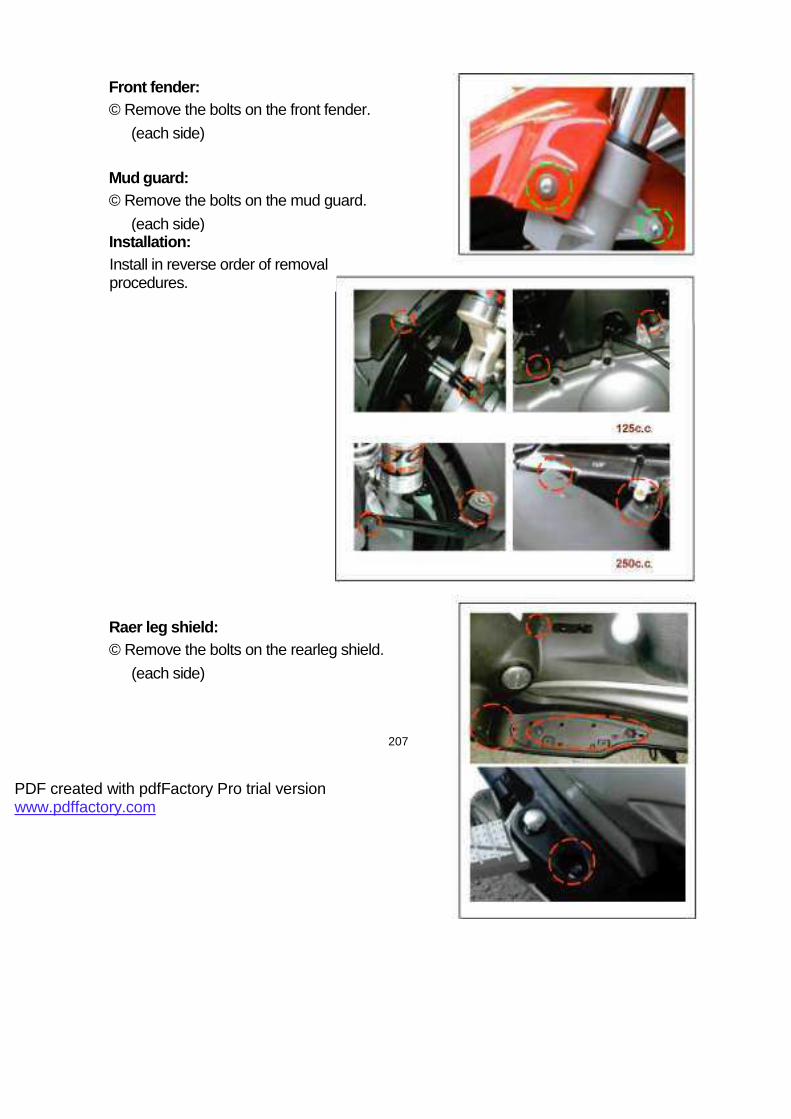
Front fender:
© Remove the bolts on the front fender.
(each side)
Mud guard:
© Remove the bolts on the mud guard.
(each side)
Raer leg shield:
© Remove the bolts on the rearleg shield.
(each side)

Fronnt leg shield cover:
© Remove the nuts and screw
on the fronnt leg shield cover. © Fronnt leg shield cover.
Fronnt leg shield:
© Remove the bolts on the fronnt leg shield.
(each side) © Fronnt leg shield.
Leg shield cover set:
© Remove the bolts on the leg shield cover set.
Installation:
Install in reverse order of removal procedures.
208
PDF created with pdfFactory Pro trial version www.pdffactory.com

Wind shield:
© Remove the bolts on the wind shield.
(each side) © Wind shield.
Front speedometer cover:
© Remove the screws on the Front speedometer cover. (each
side)
Speedometer cover:
© Remove the screws on the
speedometer cover.(each side)
Installation:
Install in reverse order of removal procedures.
209
PDF created with pdfFactory Pro trial version www.pdffactory.com

4-4-2 Removal and Inspection of Front Fork & Steering
CU8 & CUB
1. FORK COMP, FRONT
2. SHOCK ABSORBER ASSY
3. SUSPENSION ARM, LH. &
RH.
4. FIXED PLATE, LH. & RH.
CU8-B & CUB-B
1. FORK COMP, FRONT
2. FORK COMP, FRONT LH. &
RH.
Z1U
1. HANDLE BAR ASSY
2. GRIP
3. CABLE
4. CABLE, THRORRLE
PDF created with pdfFactory Pro trial version www.pdffactory.com

CU8 & CUB:
® Remove upper and lower bolts
on the shock absorber assy. © Shock
absorber assy. © Remove the bolts on the
suspension ram. © Suspension ram.
CU8-B & CUB-B:
© Remove the bolts on the fork comp.
© Remove 4 nuts.
© Fork comp, front LH. & RH.
4-4-3 Removal and Assembly of Wheel
and Shock absorber
Front wheel:
Watch: Please place main stand to park the motorcycle
for maintenance.
Removal:
© Remove 2 bolts on the caliper.
© Caliper.
© Remove bolt and collar.
© Remvoe speed meter cable nut. Note: Do not apply
brake when removing caliper from brake disk. Otherwise,
the lining can contact.
© Front wheel.
Inspection: Check eccentricity and wear condition. Note:
If eccentricity is higher than 0.2mm, please replace with
new one to ensure driving safety.
© Speed meter gear assembly. *Inspection of Wheel
Rim* Put wheel rim on rotation stand. Rotate the wheel
slowly and use dial-gauge to measure eccentricity Note:
(1) The transverse eccentricity should be
within 3.0 mm. If the condition is poor,
please replace with new one. (2) The lateral eccentricity should be within 3.0mm. If the condition is poor, please replace with new one.
211
PDF created with pdfFactory Pro trial version www.pdffactory.com

Rear wheel:
Watch: Please place main stand to park the motorcycle for maintenance.
Removal:
© Remove 2 bolts on the caliper.
© Caliper.
© Remove the nut.
© Rearwheel. Note:
(1) Please use vacuum to clean wheel ri m and lining.
Try to reduce the contamination of asbestos fiber, which
may affect the human breath system or lead to cancer.
(2) The transverse eccentricity should be within 3.0mm.
If the condition is poor, please replace with new one.
(3) The lateral eccentricity should be within 3.0 mm.
If the condition is poor, please replace with new one.
Installation:
Install in reverse order of removal procedures.
Shock absorber:
Front:
Watch: Please place main stand to park the
motorcycle for maintenance.
Removal:
© Remove upper and lower attaching bolts
on front shock absorber.(each side 2 bolts) © Shock
absorber.
Inspection: Check if the shock absorber is worn, scratched, leaking, or bent. If its condition is poor, please replace with new one. Note: Torque of shock absorber upper and lower attaching bolts: 200 ~ 300 kg-cm.
Rear: © Remove 2 attaching bolts on air filter. © Airfilter. © Remove upper and lower attaching bolts
on rear shock absorber.(each side 2 bolts) © Shock absorber.
212
PDF created with pdfFactory Pro trial version www.pdffactory.com

Inspection: Check if the shock absorber is worn, scratched, leaking, or bent. If its condition is poor, please replace with new one. Note: Torque of shock absorber upper and lower attaching bolts: 200 ~ 300 kg-cm
Installation:
Install in reverse order of removal procedures.
213
PDF created with pdfFactory Pro trial version www.pdffactory.com

4-5 Brake system:
CU8 & CUB
1:MASTER CYLINDER
2:HOSE ASSY 3:CALIPER 4:PAD ASSY 5:DISC,BRAKE 6:REAR FORK ASSY
214
PDF created with pdfFactory Pro trial version www.pdffactory.com

CU8-B & CUB-B
1:MASTER CYLINDER
2:HOSE ASSY 3:CALIPER 4:PAD ASSY 5:DISC,BRAKE 6:REAR FORK ASSY
215
PDF created with pdfFactory Pro trial version www.pdffactory.com
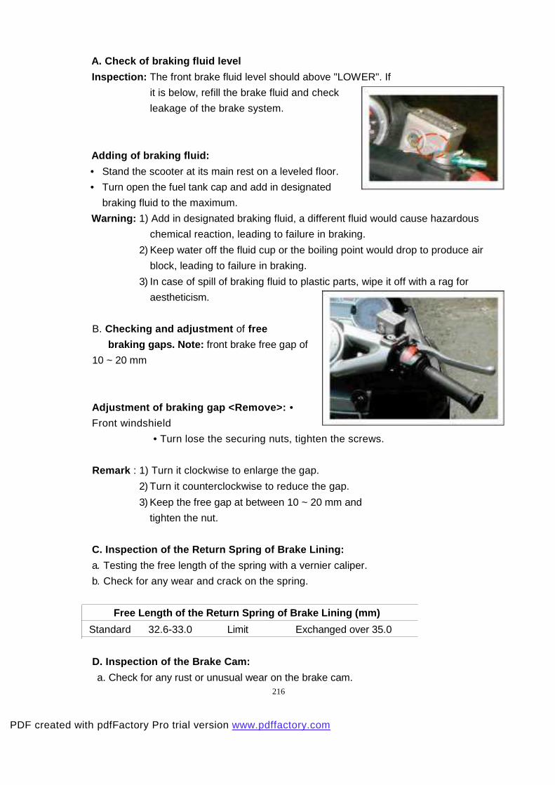
A. Check of braking fluid level
Inspection: The front brake fluid level should above "LOWER". If
it is below, refill the brake fluid and check
leakage of the brake system.
Adding of braking fluid:
• Stand the scooter at its main rest on a leveled floor.
• Turn open the fuel tank cap and add in designated
braking fluid to the maximum.
Warning: 1) Add in designated braking fluid, a different fluid would cause hazardous
chemical reaction, leading to failure in braking.
2) Keep water off the fluid cup or the boiling point would drop to produce air
block, leading to failure in braking.
3) In case of spill of braking fluid to plastic parts, wipe it off with a rag for
aestheticism.
B. Checking and adjustment of free
braking gaps. Note: front brake free gap of
10 ~ 20 mm
Adjustment of braking gap <Remove>: •
Front windshield
• Turn lose the securing nuts, tighten the screws.
Remark : 1) Turn it clockwise to enlarge the gap.
2) Turn it counterclockwise to reduce the gap.
3) Keep the free gap at between 10 ~ 20 mm and
tighten the nut.
C. Inspection of the Return Spring of Brake Lining:
a. Testing the free length of the spring with a vernier caliper.
b. Check for any wear and crack on the spring.
Free Length of the Return Spring of Brake Lining (m m)
Standard 32.6-33.0 Limit Exchanged over 35.0
D. Inspection of the Brake Cam:
a. Check for any rust or unusual wear on the brake cam. 216
PDF created with pdfFactory Pro trial version www.pdffactory.com

b. Make sure the brake cam runs smoothly.
c. Make sure to apply sufficient grease to the brake cam and lining anchor-pin.
E. Inspection of Front Brake:
a. Check the gap between the ends of front brake lever.
Gap of Front Brake Lever
10 ~20 mm ___________
b. Add brake oil.
c. Check the brake lining.
F. Inspection of Rear Brake:
a. Check the gap between the
ends of rear brake lever.
b. Move the adjusting nut of brake cable clockwise to proper gap.
Gap of Rear Brake Lever
10~20 mm
217
PDF created with pdfFactory Pro trial version www.pdffactory.com