xlpr sim editor 1.0 user's guidexlpr sim editor 1.0 user’s guide . 10 • matthew homiack...
TRANSCRIPT
SANDIA REPORT SAND2017-3166 Unlimited Release Printed March 2017
xLPR Sim Editor 1.0 User’s Guide
Paul E. Mariner Prepared by Sandia National Laboratories PO Box 5800 Albuquerque, New Mexico 87185-0747 Sandia National Laboratories is a multi-mission laboratory managed and operated by Sandia Corporation, a wholly owned subsidiary of Lockheed Martin Corporation, for the U.S. Department of Energy's National Nuclear Security Administration under contract DE-AC04-94AL85000. Approved for public release; further dissemination unlimited.

xLPR Sim Editor 1.0 User’s Guide
2
Issued by Sandia National Laboratories, operated for the United States Department of Energy by Sandia Corporation. NOTICE: This report was prepared as an account of work sponsored by an agency of the United States Government. Neither the United States Government, nor any agency thereof, nor any of their employees, nor any of their contractors, subcontractors, or their employees, make any warranty, express or implied, or assume any legal liability or responsibility for the accuracy, completeness, or usefulness of any information, apparatus, product, or process disclosed, or represent that its use would not infringe privately owned rights. Reference herein to any specific commercial product, process, or service by trade name, trademark, manufacturer, or otherwise, does not necessarily constitute or imply its endorsement, recommendation, or favoring by the United States Government, any agency thereof, or any of their contractors or subcontractors. The views and opinions expressed herein do not necessarily state or reflect those of the United States Government, any agency thereof, or any of their contractors. Printed in the United States of America. This report has been reproduced directly from the best available copy. Available to DOE and DOE contractors from U.S. Department of Energy Office of Scientific and Technical Information P.O. Box 62 Oak Ridge, TN 37831 Telephone: (865) 576-8401 Facsimile: (865) 576-5728 E-Mail: [email protected] Online ordering: http://www.osti.gov/bridge Available to the public from U.S. Department of Commerce National Technical Information Service 5285 Port Royal Rd. Springfield, VA 22161 Telephone: (800) 553-6847 Facsimile: (703) 605-6900 E-Mail: [email protected] Online order: http://www.ntis.gov/help/ordermethods.asp?loc=7-4-0#online
xLPR Sim Editor 1.0 User’s Guide
3
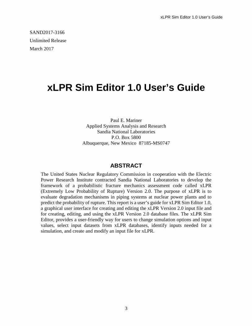
SAND2017-3166
Unlimited Release
March 2017
xLPR Sim Editor 1.0 User’s Guide
Paul E. Mariner Applied Systems Analysis and Research
Sandia National Laboratories P.O. Box 5800
Albuquerque, New Mexico 87185-MS0747
ABSTRACT The United States Nuclear Regulatory Commission in cooperation with the Electric Power Research Institute contracted Sandia National Laboratories to develop the framework of a probabilistic fracture mechanics assessment code called xLPR (Extremely Low Probability of Rupture) Version 2.0. The purpose of xLPR is to evaluate degradation mechanisms in piping systems at nuclear power plants and to predict the probability of rupture. This report is a user’s guide for xLPR Sim Editor 1.0, a graphical user interface for creating and editing the xLPR Version 2.0 input file and for creating, editing, and using the xLPR Version 2.0 database files. The xLPR Sim Editor, provides a user-friendly way for users to change simulation options and input values, select input datasets from xLPR databases, identify inputs needed for a simulation, and create and modify an input file for xLPR.

xLPR Sim Editor 1.0 User’s Guide
4
ACKNOWLEDGMENTS The author would like to thank David Rudland of the U.S. Nuclear Regulatory Commision (NRC) Office of Nuclear Regulatory Research, Craig Harrington of Electric Power Research Institute (EPRI), and the xLPR Computational Task Group Lead, Remi Dingreville of Sandia National Laboratories (SNL), for their support of the xLPR Sim Editor project. I also would like to thank Greg Madrid of SNL and other participants in the xLPR Computational Task Group for helpful comments and feedback on this user’s guide.

xLPR Sim Editor 1.0 User’s Guide
5
ABBREVIATIONS AND ACRONYMS
DB Database
DM Dissimilar metal
DOE U.S. Department of Energy
EFPY Effective full power years
EPRI Electric Power Research Institute
ID Inner diameter of pipe
LBB Leak-Before-Break
MSIP Mechanical stress improvement process
NRC U.S. Nuclear Regulatory Commission
RPV Release pressure valve
SCC Stress corrosion cracking
SG Steam generator
SM Similar metal
SNL Sandia National Laboratories
WOL Weld overlay
WRS Weld residual stress
xLPR Extremely Low Probability of Rupture software, version 2.0

xLPR Sim Editor 1.0 User’s Guide
6
CONTENTS
Abstract ........................................................................................................................................... 3
Acknowledgments........................................................................................................................... 4
Abbreviations and Acronyms ......................................................................................................... 5
Contents .......................................................................................................................................... 6
Figures............................................................................................................................................. 8
1 Introduction ............................................................................................................................. 9
1.1 General Information ........................................................................................................ 9
1.2 Authorized Use Permission............................................................................................. 9
1.3 Points of Contact ............................................................................................................. 9
1.4 Change Record .............................................................................................................. 10
1.5 Disclaimer ..................................................................................................................... 10
2 Software Summary ................................................................................................................ 11
2.1 Platform......................................................................................................................... 11
2.2 Framework Configuration ............................................................................................. 11
2.2.1 xLPR Sim Editor 1.0 Software ............................................................................. 11 2.2.2 Java 8 Update 51 or Higher .................................................................................. 12 2.2.3 Input Set ................................................................................................................ 12 2.2.4 Database Files ....................................................................................................... 12 2.2.5 Output Files ........................................................................................................... 12
3 Installation ............................................................................................................................. 13
4 Execution ............................................................................................................................... 15
4.1 Opening the Software ................................................................................................... 15
4.2 Sim Editor Basics .......................................................................................................... 16
4.2.1 Display Filtering ................................................................................................... 16 4.2.2 Input Ranges ......................................................................................................... 16 4.2.3 Parameter Distributions ........................................................................................ 17 4.2.4 Units ...................................................................................................................... 18 4.2.5 Errors and Warnings ............................................................................................. 18
4.3 Get Started Menu .......................................................................................................... 18
4.4 Simulation Mode ........................................................................................................... 19
4.4.1 Simulation Tab ...................................................................................................... 20 4.4.2 Share Tab .............................................................................................................. 36 4.4.3 Tools Tab .............................................................................................................. 37 4.4.4 Help Tab................................................................................................................ 37
xLPR Sim Editor 1.0 User’s Guide
7
4.5 Database Mode.............................................................................................................. 38
4.5.1 Get Started ............................................................................................................ 39 4.5.2 Weld Type Database ............................................................................................. 39 4.5.3 Material Database ................................................................................................. 41 4.5.4 Axial and Hoop WRS Databases .......................................................................... 42 4.5.5 Share, Tools, Help, and Installer Build ................................................................. 43
5 Conclusions ........................................................................................................................... 45
6 References ............................................................................................................................. 47
Distribution ................................................................................................................................... 48

xLPR Sim Editor 1.0 User’s Guide
8
FIGURES
Figure 1. xLPR Sim Editor system requirements. ........................................................................ 11 Figure 2. xLPR Sim Editor home page. ........................................................................................ 15 Figure 3. Example of input fields and input ranges. ..................................................................... 17 Figure 4. Example of parameter distribution fields. ..................................................................... 17 Figure 5. Get Started menu. .......................................................................................................... 18 Figure 6. Database configuration. ................................................................................................. 19 Figure 7. Simulation settings. ....................................................................................................... 20 Figure 8. Weld properties. ............................................................................................................ 22 Figure 9. WRS selection panel...................................................................................................... 23 Figure 10. Example plot of mean WRS curve, mean plus two standard deviations, and mean
minus two standard deviations. .................................................................................... 24 Figure 11. Operating Periods panel. ............................................................................................. 24 Figure 12. TIFFANY Parameters panel. ....................................................................................... 27 Figure 13. Example plot of thermal transient. .............................................................................. 27 Figure 14. Mitigation options. ...................................................................................................... 28 Figure 15. Crack Initiation Type panel. ........................................................................................ 29 Figure 16. LEAPOR parameters panel. ........................................................................................ 31 Figure 17. Inspection & Leak Detection. ...................................................................................... 31 Figure 18. Correlations panel. ....................................................................................................... 33 Figure 19. Weld material inputs.................................................................................................... 34 Figure 20. PWSCC Initiation panel for mitigation material. ........................................................ 36 Figure 21. Share tab. ..................................................................................................................... 36 Figure 22. Tools tab. ..................................................................................................................... 37 Figure 23. Help tab. ...................................................................................................................... 38 Figure 24. Database mode showing Weld Type database. ........................................................... 39 Figure 25. Materials database. ...................................................................................................... 41 Figure 26. Axial WRS database. ................................................................................................... 42
xLPR Sim Editor 1.0 User’s Guide
9
1 INTRODUCTION 1.1 General Information This user’s guide describes the installation and use of xLPR Sim Editor 1.0. The xLPR Sim Editor is a graphical user interface for the input file and database files of Version 2.0 of the xLPR (Extremely Low Probability of Rupture) code. xLPR is a probabilistic fracture mechanics software package for predicting crack initiation and growth in pipe welds and also probabilities of pipe rupture subjected to normal and transient stresses over a plant’s operational life. Input parameters for the xLPR code are described in detail in the xLPR user’s manual and other xLPR documentation (xLPR-SDD-FW 2016; xLPR-UM-FW 2016).
The input file and database files for the xLPR code are Microsoft Excel files. They contain all of the data blocks used as input in an xLPR simulation and by the TIFFANY and LEAPOR pre-processor of xLPR. The Sim Editor is designed to provide an organized, user-friendly, and menu-driven way to generate a new input file or to modify an existing input file or database file. To that end, the Sim Editor organizes inputs using menus and tabs and hides input parameters that are not relevant to the features and processes selected for simulation. In addition, the software warns the user of out-of-range values for inputs and provides helpful instruction and tools. The Sim Editor further provides a way to create and update datasets of material properties, weld types, and weld residual stress (WRS). Datasets from these databases may be selected and imported into a simulation input file using the Sim Editor.
1.2 Authorized Use Permission Funding for this work was provided by the Nuclear Regulatory Commission (NRC, B&R Number 450140374) through the following Interagency Agreements:
• N6829 "xLPR Initial Framework Development" • V6143/V6233 “Continuing xLPR Development” • V6260 “xLPR Version 2 Development” and • NRC-HQ-25-14-D-0005/NRC-HQ-60-16-T-0007 “Application of xLPR Version 2 Code
in Support of Leak-Before-Break (LBB) Regulatory Guide Development.
The statutory, regulatory, and procedural intellectual property policies of the DOE are applicable to the work falling under this work order. Therefore, NRC and DOE requirements for release of portions of this software, codes, or other proprietary information must be strictly adhered to.
Sandia National Laboratories (SNL), to the extent it is permitted to and asserts copyright therein, grants a royalty-free, nonexclusive, irrevocable worldwide license to the Government to use, reproduce, modify, distribute, prepare derivative works, release, display or disclose the articles, reports, summaries, abstracts, and related documents developed under this Agreement, for any governmental purposes and to have or authorize others to do so.
1.3 Points of Contact The points of contact for the xLPR framework are
• Remi Dingreville (SNL) [email protected]

xLPR Sim Editor 1.0 User’s Guide
10
• Matthew Homiack (NRC) [email protected] The point of contact for the Sim Editor is
• Paul Mariner (SNL) [email protected]
1.4 Change Record The xLPR Sim Editor and this user’s guide are not quality controlled xLPR products. There are two principal reasons for excluding these products from the xLPR quality assurance program. First, use of the Sim Editor is not required for xLPR simulation. The purpose of the Sim Editor and this guide is simply to help the user prepare and modify model options and parameter values in the xLPR input and database files. The second reason is that the user need only use Microsoft Excel to inspect the files generated or modified by the Sim Editor to ensure that they are correct.
1.5 Disclaimer Though the xLPR Sim Editor has been tested throughout its development, as explained in the previous section, the Sim Editor is not part of the xLPR quality assurance program. Use of the Sim Editor is at the user’s own risk. The Sim Editor output files can be inspected using Microsoft Excel to ensure entries are correct. Bugs in the Sim Editor should be reported as described in Section 4.4.2.
xLPR Sim Editor 1.0 User’s Guide
11
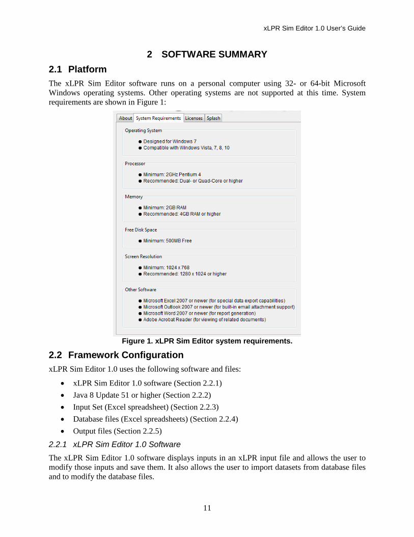
2 SOFTWARE SUMMARY 2.1 Platform The xLPR Sim Editor software runs on a personal computer using 32- or 64-bit Microsoft Windows operating systems. Other operating systems are not supported at this time. System requirements are shown in Figure 1:
Figure 1. xLPR Sim Editor system requirements.
2.2 Framework Configuration xLPR Sim Editor 1.0 uses the following software and files:
• xLPR Sim Editor 1.0 software (Section 2.2.1) • Java 8 Update 51 or higher (Section 2.2.2) • Input Set (Excel spreadsheet) (Section 2.2.3) • Database files (Excel spreadsheets) (Section 2.2.4) • Output files (Section 2.2.5)
2.2.1 xLPR Sim Editor 1.0 Software The xLPR Sim Editor 1.0 software displays inputs in an xLPR input file and allows the user to modify those inputs and save them. It also allows the user to import datasets from database files and to modify the database files.
xLPR Sim Editor 1.0 User’s Guide
12
2.2.2 Java 8 Update 51 or Higher The xLPR Sim Editor 1.0 is written in the Java programming language and runs in the Java Runtime Environment. The xLPR Sim Editor 1.0 requires Java 8 Update 51. This version of Java is already provided in the xLPR Sim Editor 1.0 installer and will be installed automatically.
2.2.3 Input Set The Input Set is the Microsoft Excel input file that the xLPR software uses to define and bound an xLPR simulation. For xLPR simulation, this file must be named xLPR-2.0 Input Set.xlsx. However, the Sim Editor has no restriction on the file name. The various worksheets within the Input Set contain the simulation options and the values of all user-provided simulation parameters.
2.2.4 Database Files The Sim Editor manages four database files. They are
• xLPR-2.0 DB - Axial WRS.xlsx
• xLPR-2.0 DB - Hoop WRS.xlsx
• xLPR-2.0 DB - Materials.xlsx
• xLPR-2.0 DB - Weld Type.xlsx Each file is a Microsoft Excel workbook. Each worksheet within each workbook contains a unique dataset within the database file.
WRS Databases – The Axial and Hoop WRS databases provide axial and hoop WRS profiles. The names of the worksheets indicate
• type of weld (e.g., steam generator, release pressure valve, etc.) • weld repair state (%) • post-mitigation, if applicable (e.g., mechanical stress improvement process (MSIP), weld
overlay (WOL), inlay/onlay) Materials Database – The Materials database contains property datasets for different pipe and weld materials. Datasets restricted to pipe materials have “Base Only” in the name. Each worksheet in the Materials database has the general format of the Left Pipe, Right Pipe, Weld, and Mitigation worksheets in the Input Set. The names of the worksheets in the Materials database identify the material represented by the worksheet.
Weld Type Database – The Weld Type database is a collection of inputs mainly from the Properties worksheet of the Input Set. Each dataset in this database represents a specific system under specific conditions.
2.2.5 Output Files The output of the Sim Editor may be any of the following Microsoft Excel files:
• a revised or new Input Set, • a revised or new WRS, Materials, or Weld Type database.

xLPR Sim Editor 1.0 User’s Guide
13
3 INSTALLATION The steps for installing the xLPR Sim Editor are
1. Download the Sim Editor installer from https://connect.sandia.gov/sites/xLPR/SitePages/homepage.aspx. The user will have to register for an account at this web site if not already registered.
2. Run the installer.
3. During installation, follow the instructions provided by the installer. The default destination for the installation is C:\Program Files (x86)\xLPR Sim Editor 1.0.
At completion the user will have an xLPR Sim Editor icon on the desktop and/or an xLPR Sim Editor button under the Windows Start button.
Once installed, each execution of the Sim Editor will place or replace several working files and database files in a new or existing SandiaNationalLaboratories subdirectory of C:\Users\Public. The files include a default Input Set and the four database files listed in Section 2.2.4. Database files will not be replaced if they already exist (see Section 4.3).

xLPR Sim Editor 1.0 User’s Guide
14

xLPR Sim Editor 1.0 User’s Guide
15
4 EXECUTION This section addresses starting the Sim Editor, selecting options, navigating through the various panels, and using the software to
• view and edit an Input Set, and
• view, edit, and use the WRS, Materials, or Weld Type database files.
4.1 Opening the Software The xLPR Sim Editor is opened by either double-clicking on the xLPR Sim Editor icon on the desktop or by single-clicking the xLPR Sim Editor in the directory in All Programs under the Windows start menu.
The xLPR Sim Editor opens to the Sim Editor home page. The home page is shown in Figure 2.
Figure 2. xLPR Sim Editor home page.
The home page includes many features that are available at all times within the Sim Editor. These features include
• Top border that displays the path and file name of Input Set (see Figure 7)
• A round File button for various saving options
• Small buttons above the tabs for navigation and file saving
• Tabs for different purposes
o Get Started (Section 4.3) o Share (Section 4.4.2)
xLPR Sim Editor 1.0 User’s Guide
16
o Tools (Section 4.4.3) o Help (Section 4.4.4)
• Space under the tabs for a ribbon of buttons specific to the tab selected
• Information field below the ribbon for warnings and errors (see Figure 7)
• Bottom border for Sim Editor status, memory usage, and options for memory usage and window resolution.
The space below the ribbon of buttons and above the bottom border is used for displaying and editing Input Sets and xLPR databases.
4.2 Sim Editor Basics As indicated by the buttons under the Get Started tab on the home page (Figure 2), the Sim Editor has two modes of operation, simulation mode and database mode. In simulation mode (Section 4.4), the user may view and modify an xLPR input file. In database mode (Section 4.5), the user may view and modify an xLPR database file.
Inputs include model options and parameter values. Model options are user selections for the simulation. Model options include mitigation options, process model options, sampling distribution options, etc. The Sim Editor generally provides available options in a drop-down box. Parameter values, for the purposes of this user’s guide, are generally input values that may be uncertain and/or may be sampled from a distribution if so desired.
In both simulation mode and database mode, additional information about a parameter or model option may be obtained by hovering the pointer over the name of the parameter or model option. Full descriptions of parameters and model options may be found in supporting xLPR documentation (xLPR-SDD-FW 2016; xLPR-UM-FW 2016).
4.2.1 Display Filtering In simulation mode, input panels are filtered to display only those inputs and input panels relevant to the simulation. Filtering is dependent on user selections of model options. Display filtering is coded into the Sim Editor to help the user determine which parameters are necessary for the simulation. In database mode, display filtering is disabled.
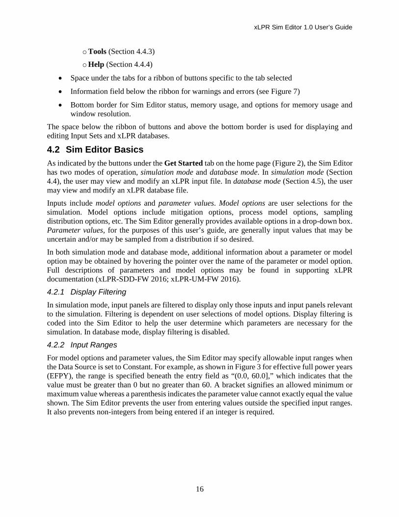
4.2.2 Input Ranges For model options and parameter values, the Sim Editor may specify allowable input ranges when the Data Source is set to Constant. For example, as shown in Figure 3 for effective full power years (EFPY), the range is specified beneath the entry field as “(0.0, 60.0],” which indicates that the value must be greater than 0 but no greater than 60. A bracket signifies an allowed minimum or maximum value whereas a parenthesis indicates the parameter value cannot exactly equal the value shown. The Sim Editor prevents the user from entering values outside the specified input ranges. It also prevents non-integers from being entered if an integer is required.

xLPR Sim Editor 1.0 User’s Guide
17
Figure 3. Example of input fields and input ranges.
When Data Source is Aleatory or Epistemic, e.g., as shown in Figure 4, valid input ranges are not displayed and the Sim Editor does not check whether the entered distribution honors the allowed range. It is up to the user to make sure that the distribution honors the allowed range. Entering appropriate minimum and maximum values for the distribution is one way to do that (e.g., see Figure 4). The user can check the allowed range by momentarily selecting Constant for the Data Source.
Figure 4. Example of parameter distribution fields.
4.2.3 Parameter Distributions For parameter values that may be entered as distributions, the following entry fields are available when the Data Source (e.g., Figure 3) is set to Constant:
• Data Source (“Constant” is selected)
• Value
• Units
When a distribution is entered for a parameter value (e.g., Figure 4), the following entry fields are available:
• Data Source (“Aleatory” or “Epistemic” is selected)
• Units
• Importance sampling (yes or no)
• Importance value (value between 0 and 1)
• Distribution (type of sampling distribution selected)
• Fields to describe the distribution selected

xLPR Sim Editor 1.0 User’s Guide
18
Values to enter for certain distributions are not always straightforward. Values to enter for lognormal and log uniform distributions are explained in the Entering Distributions link of the Help tab (Section 4.4.4).
Often, there are optional parameters to enter for the distributions, indicated with brackets. For example, some distributions may be truncated with maximum and minimum values (e.g., Figure 4). For optional maximum and minimum values, both must be entered for xLPR to run. The Sim Editor will not allow only one being entered.
4.2.4 Units Units available for entry are provided in the Units link of the Help tab. For certain parameters the units are fixed and cannot be edited.
4.2.5 Errors and Warnings Errors and warnings are tallied by the Sim Editor at the yellow banner beneath the button ribbon. They are viewed by clicking the View button in the banner (e.g., Figure 7). Symbols indicating errors and warnings also appear in the input panels and input panel buttons.
The warnings often provide information about which input panels are not viewable due to simulation settings. For example, “Fatigue Initiation: N/A – This panel does not apply due to the defined crack initiation type.”
Errors are caused by invalid input values. Invalid inputs may occur after importing a new Input Set. They may also occur after changing an input value that affects input ranges for other parameters. Occasionally, in simulation mode an error may be in an input panel that the Sim Editor does not display because of the simulation options selected. If the input is not displayed, it is not used in the xLPR simulation. To remove an error flag in this situation, the user must temporarily change the simulation settings so that the input panel with the error will show. Then the user can change the value to be within the checked range.
4.3 Get Started Menu The buttons of the Get Started tab are shown in Figure 5. They are
• Open Simulation
• Open Database
• Database Configuration
Figure 5. Get Started menu.

xLPR Sim Editor 1.0 User’s Guide
19
Open Simulation – This button is used to load an input file for an xLPR simulation (e.g., xLPR-2.0 Input Set.xlsx). When this button is selected, the Sim Editor operates in simulation mode (Section 4.4).
Open Database – This button initiates the database mode of the xLPR Sim Editor (Section 4.5). In database mode, the user may view and edit the Weld Type, Material, and WRS databases.
Database Configuration – This button allows the user to change the path for the database files or to install the default databases that come with the Sim Editor software. This feature allows the user to view and use historical and default databases in database mode and in simulation mode.
The database configuration window is shown in Figure 6. The path to the database files is shown under “Choose the path to the database files.” This path may be changed by the user. The default path is shown in the figure. The Default Path button replaces the path with the default path. The Install DB Files button installs or replaces the database files at the chosen path with the files that come with the Sim Editor. Changes in database configuration are saved using the Save button.
Figure 6. Database configuration.
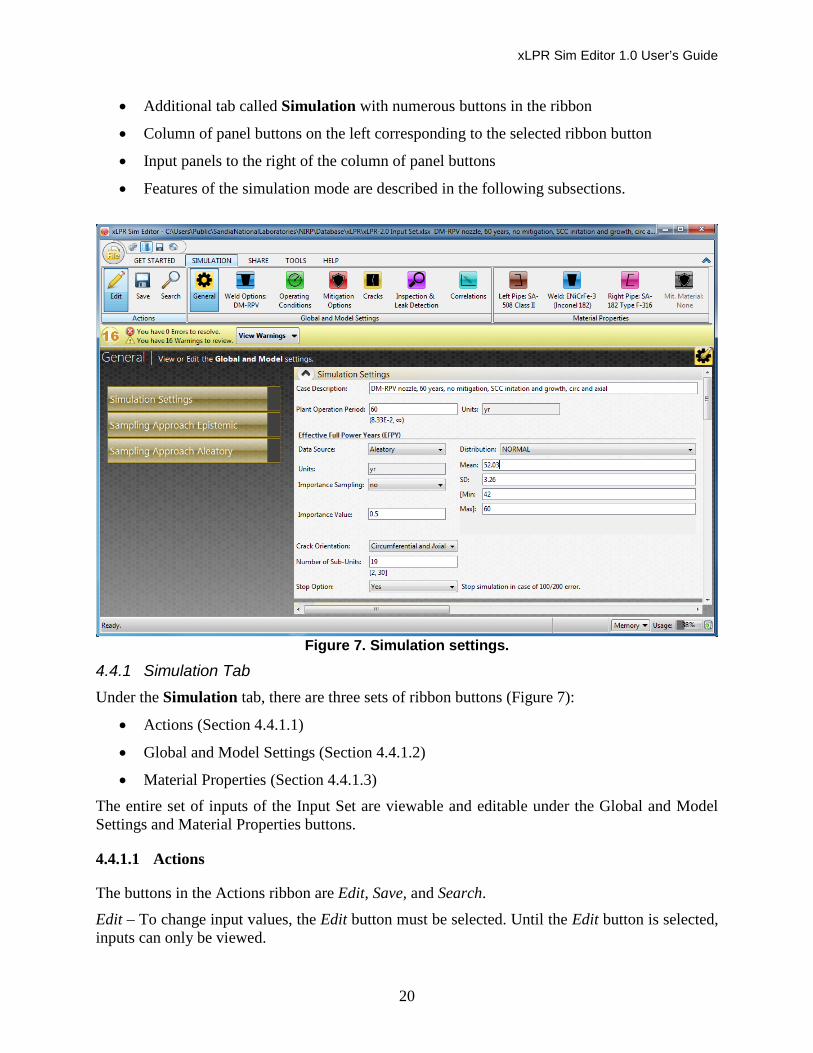
4.4 Simulation Mode When the Open Simulation button is selected, the user must select an Input Set to open. New Input Sets are not created from scratch. The user may select a customized Input Set, a default Input Set, or a test case Input Set from the xLPR software package or the Sim Editor software package. For xLPR simulation, the name of the file must be xLPR-2.0 Input Set.xlsx; however, the Sim Editor will load any Excel file with the appropriate Input Set format. The Sim Editor allows the user to save Input Sets with different names and in different directories. Users often elect to keep the xLPR-2.0 Input Set.xlsx filename for all Input Sets and place different Input Sets in different descriptively-named directories. The Sim Editor will open the selected Input Set after checking the file for validity.
An example of the Sim Editor display in simulation mode is shown in Figure 7. In simulation mode, the Sim Editor shows
xLPR Sim Editor 1.0 User’s Guide
20
• Additional tab called Simulation with numerous buttons in the ribbon
• Column of panel buttons on the left corresponding to the selected ribbon button
• Input panels to the right of the column of panel buttons
• Features of the simulation mode are described in the following subsections.
Figure 7. Simulation settings.
4.4.1 Simulation Tab Under the Simulation tab, there are three sets of ribbon buttons (Figure 7):
• Actions (Section 4.4.1.1)
• Global and Model Settings (Section 4.4.1.2)
• Material Properties (Section 4.4.1.3) The entire set of inputs of the Input Set are viewable and editable under the Global and Model Settings and Material Properties buttons.
4.4.1.1 Actions
The buttons in the Actions ribbon are Edit, Save, and Search.
Edit – To change input values, the Edit button must be selected. Until the Edit button is selected, inputs can only be viewed.

xLPR Sim Editor 1.0 User’s Guide
21
Save – The Save button saves changes to the current file. To save changes to a new file, the user must select the round File button above the Action buttons and select Save As.
Search – The Search button opens a pop-up window that can be used to search for a parameter or text string within the panels of the selected button of Global and Model Settings or Material Properties.
4.4.1.2 Global and Model Settings
There are seven buttons in the Global and Model Settings ribbon. They are • General
• Weld Options
• Operating Conditions
• Mitigation Options
• Cracks
• Inspection & Leak Detection
• Correlations General – The settings under the General button are nearly all model settings and options. They are shown in Figure 7. The General button panels (•) and inputs (◦) include
• Simulation Settings o Plant operation period
o Effective full power years
o Crack orientation
o Number of sub-units
o Stop on error option
• Sampling Approach Epistemic o Sample size (epistemic)
o Random seed
o Importance sampling
o Adaptive sampling
o Discretization
• Sampling Approach Aleatory o Sample size (aleatory)
o Random seed
o Importance sampling
o Adaptive sampling
xLPR Sim Editor 1.0 User’s Guide
22
o Discretization
Weld Options – The Weld Options button shows inputs related to general weld properties. The Weld Properties panel allows the user to import a weld type from the Weld Type database (Figure 8). An import of a weld type from the database will import
• All of the inputs in the Weld Type database (Section 4.5.2) for the weld type selected, and
• All of the inputs in the Materials database (Section 4.5.3) corresponding to each material identified for the left pipe, right pipe, and weld in the Weld Type database for the weld type selection.
Material property datasets may also be imported individually from the Materials database using the material import drop-down boxes in the Weld Properties input panel. A selection of a material will import all of the inputs in the Materials database for the material.
Once imported, the input parameters, weld type name, and material names may be edited.
Figure 8. Weld properties.
The second panel button under Weld Options is WRS Type. Its input panel is shown in Figure 9. This panel shows the names of the current WRS profiles and allows the user to import WRS profiles from the Axial and Hoop WRS databases. Once imported, the user may edit the WRS name in this panel and the WRS profile in the WRS panel. To add a new or modified WRS profile to the database, the user must switch to database mode. Post-mitigation WRS fields are hidden when there is no stress mitigation in the simulation.
xLPR Sim Editor 1.0 User’s Guide
23
Figure 9. WRS selection panel.
The panels (•) and inputs (◦) under the Weld Options button include
• Weld properties
o Weld type name and import button
o Dissimilar metal/similar metal weld type
o Base material 1 name and import button
o Base material 2 name and import button
o Weld material name and import button
o Weld repair state
o Dissimilar weld mixture ratio
• WRS type
o Hoop WRS pre-mitigation name and import button
o Axial WRS pre-mitigation name and import button
o Hoop WRS post-mitigation name and import button (if applicable)
o Axial WRS post-mitigation name and import button (if applicable)
• WRS (one section for each WRS – hoop, axial, pre- and post-mitigation) o Sampling loop
o Importance sampling
o Importance value
o Correlation type
o Correlation coefficient
o Table of x/t versus stress and related normal distribution parameters
Special feature: WRS profiles may be plotted using the View Plot buttons in this panel. An example is shown in Figure 10.

xLPR Sim Editor 1.0 User’s Guide
24
• Geometry o Pipe outer diameter
o Pipe wall thickness
o Weld width
o Weld material thickness
Figure 10. Example plot of mean WRS curve, mean plus two standard deviations, and
mean minus two standard deviations.
Operating Conditions – The Operating Conditions button includes inputs used to describe general operating conditions and transients.
The operating periods are defined in the Operating Periods panel. Operating periods are time periods of unchanged normal operating conditions. Figure 11 shows an example of this panel where two operating periods are defined for a 60-year plant operation time.
Figure 11. Operating Periods panel.
The user options for using loads or stresses for each operating period are located to the right of the period end time fields as shown in Figure 11. The Load/Stress Operating Period input panels in the Sim Editor show either load inputs or stress inputs depending on the user options selected in the Operation Periods panel.
The panels (•) and inputs (◦) under the Operating Conditions button include
• General operating conditions o Flow rate

xLPR Sim Editor 1.0 User’s Guide
25
o Unmitigated H2 and Zn concentrations
o Additional surface stress at inner diameter of pipe, hoop and axial
• Operating periods o Ending times for periods 1 and 2
o Option for stress or load inputs, each period
• Load/stress operating period 1, 2, and 3 (tabs for Loads and Stresses) o Loads
Dead weight
Thermal expansion
o Stresses
Membrane
Dead weight
Thermal expansion
• Operating conditions period 1, 2, and 3 (as needed) o Pressure
o Temperature
o Dissolved oxygen
• TIFFANY parameters (if fatigue crack initiation and/or growth selected in Cracks)
o Nominal values used by TIFFANY preprocessor (Figure 12)
Changing a value here changes the parameter value elsewhere in the Sim Editor
Changing options (e.g., mitigation) here also changes the options elsewhere Units are fixed
Special feature: The Calculate Stresses button (bottom of Figure 12) allows the user to calculate the membrane and bending stresses from entered load parameters. A note above the button indicates which inputs are used.
• Transient types (if fatigue crack initiation and/or growth selected in Cracks)
o Option for Type I, Type I and II, or Type III for each transient
• Transient properties (each transient) (if fatigue crack initiation and/or growth selected in Cracks)
o Transient type
o Description of transient (frequency, etc.)
o Name of thermal transient

xLPR Sim Editor 1.0 User’s Guide
26
o Start and end times
o Front/back loading
o Frequency of events
o Number of cycles per event
o Uncertainty multiplier
• Thermal transients (each transient) (if fatigue crack initiation and/or growth selected in Cracks)
o Name of transient
o Time versus change in temperature and change in pressure
Special feature: Thermal transients may be plotted using the Plot button in this panel. An example is shown in Figure 13.
• Earthquake o Probability
o Changes in total membrane, inertial bending, and anchor bending stresses
xLPR Sim Editor 1.0 User’s Guide
27
Figure 12. TIFFANY Parameters panel.
Figure 13. Example plot of thermal transient.
Mitigation Options – The Mitigation Options button contains options for mitigation simulation and fields for parameters that describe the mitigation(s). Figure 14 shows the input panels under
xLPR Sim Editor 1.0 User’s Guide
28
the Mitigation Options button. In the Mitigation Type panel, the type of mitigation is selected. This selection determines which tabs and fields are displayed in the Mitigation Options input panel. When mitigation includes an overlay or inlay/onlay, the user can import a mitigation material from the Materials database.
Figure 14. Mitigation options.
The panels (•) and inputs (◦) under the Mitigation Options button include
• Mitigation type
o None, stress-based, chemistry-based, or stress and chemical
• Mitigation options (tabs for stress and chemical mitigation) o Stress
MSIP, WOL, or inlay/onlay
Mitigation time
Mitigation material name and import button (if applicable)
Thickness of inlay/onlay or overlay (if applicable)
o Chemistry
H2, Zn, or H2 and Zn
Mitigation time(s)
New H2 and/or Zn concentration(s)
Cracks – The Cracks button contains options and parameters specific to crack initiation and crack growth, except for those parameters that are also specific to the material. Parameters that are specific to the material are located under the Material Properties buttons (Section 4.4.1.3).
The first input panel under the Cracks button is Crack Initiation Type. It is shown in Figure 15. The type of crack initiation is selected at the top of this panel. If stress corrosion cracking (SCC) is included in the type of crack initiation, the SCC Initiation Method option appears.

xLPR Sim Editor 1.0 User’s Guide
29
Figure 15. Crack Initiation Type panel.
Several other input panels under the Cracks button have important options to select. They include Crack Growth, Coalescence, and Stability.
The panels (•) and inputs (◦) under the Cracks button include
• Crack initiation type
o Initial flaw, SCC initiation, fatigue initiation, or SCC and fatigue initiation
o SCC initiation model (if applicable)
• Crack initiation (tabs for initial flaw, fatigue, and SCC) o Initial flaw density
Number of flaws, circumferential and axial (as applicable)
Initial flaw length and multiplier
Initial flaw depth and multiplier
o Fatigue initiation
Initial flaw length and multiplier
Initial flaw depth and multiplier
o SCC initiation
Initial flaw length and multiplier
Initial flaw depth and multiplier
• Crack growth o SCC, fatigue, or SCC and fatigue crack growth
o Option for SCC growth in pipe (for axial cracks)
o Fatigue temperature logic
o Fatigue growth CKTH parameter

xLPR Sim Editor 1.0 User’s Guide
30
• Coalescence (for circumferential cracks) o Direction
o Surface distance rule
o Depth averaging rule
o Surface crack distance rule modifier
o Through-wall crack distance rule modifier
• Stability o Constant depth or semi-elliptical
o Tolerances for call reduction to crack stability
Maximum time between calls
Exponent for call reduction equation
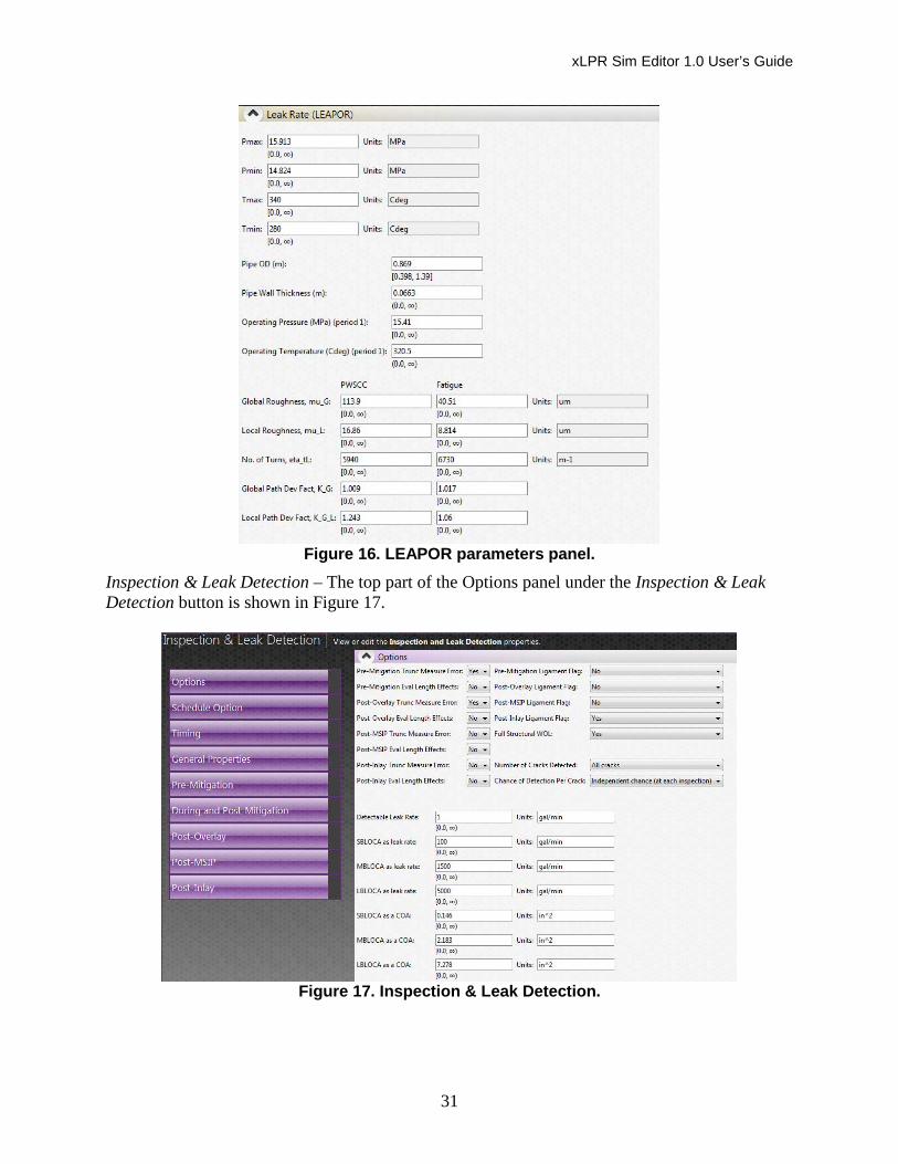
• Leak rate (LEAPOR) (all inputs used by LEAPOR preprocessor) (shown in Figure 16) o Crack mechanism
o Flow rate flag
o Range of pressure
o Range of temperature
o Nominal values of following parameters (Changing a value here changes the parameter value elsewhere in the Sim Editor. Units are fixed.)
Pipe outer diameter
Pipe wall thickness
Operating pressure (period 1)
Operating temperature (period 1)
o Global roughness
o Local roughness
o Number of turns
o Global path deviation factor
o Local path deviation factor
xLPR Sim Editor 1.0 User’s Guide
31
Figure 16. LEAPOR parameters panel.
Inspection & Leak Detection – The top part of the Options panel under the Inspection & Leak Detection button is shown in Figure 17.
Figure 17. Inspection & Leak Detection.
xLPR Sim Editor 1.0 User’s Guide
32
The panels (•) and inputs (◦) under the Inspection & Leak Detection button include
• Options o Various options
o Detectable leak rate
o Small, medium, and large LOCA
• Schedule option o By table or by frequency
• Timing o Schedule table
o Frequencies
• General properties
o PODeff, xSmall, ISmall, POD0, xUB, c, d, LenLB, LenUB, LenTH
• Pre-mitigation o Intercepts, slopes, sigma_depth, other parameters
• During and post-mitigation o xTH (during), xTH (post)
• Post-overlay o Intercepts, slopes, sigma_depth, other parameters
• Post-MSIP o Intercepts, slopes, sigma_depth, other parameters
• Inlay o Intercepts, slopes, sigma_depth, other parameters
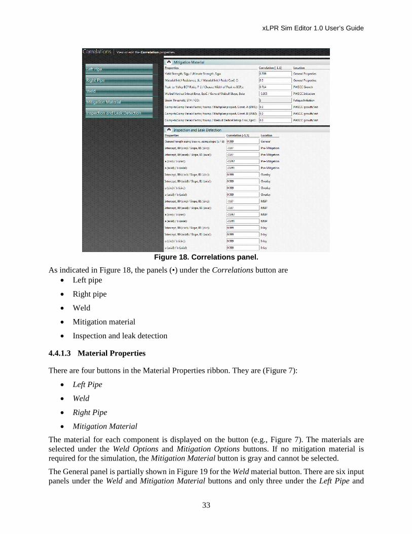
Correlations – Specific correlations between material properties and between inspection and leak detection parameters may be entered under the Correlations button. Two of these panels are shown in Figure 18.
xLPR Sim Editor 1.0 User’s Guide
33
Figure 18. Correlations panel.
As indicated in Figure 18, the panels (•) under the Correlations button are • Left pipe
• Right pipe
• Weld
• Mitigation material
• Inspection and leak detection
4.4.1.3 Material Properties
There are four buttons in the Material Properties ribbon. They are (Figure 7):
• Left Pipe
• Weld
• Right Pipe
• Mitigation Material The material for each component is displayed on the button (e.g., Figure 7). The materials are selected under the Weld Options and Mitigation Options buttons. If no mitigation material is required for the simulation, the Mitigation Material button is gray and cannot be selected.
The General panel is partially shown in Figure 19 for the Weld material button. There are six input panels under the Weld and Mitigation Material buttons and only three under the Left Pipe and
xLPR Sim Editor 1.0 User’s Guide
34
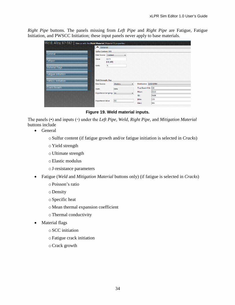
Right Pipe buttons. The panels missing from Left Pipe and Right Pipe are Fatigue, Fatigue Initiation, and PWSCC Initiation; these input panels never apply to base materials.
Figure 19. Weld material inputs.
The panels (•) and inputs (◦) under the Left Pipe, Weld, Right Pipe, and Mitigation Material buttons include
• General o Sulfur content (if fatigue growth and/or fatigue initiation is selected in Cracks)
o Yield strength
o Ultimate strength
o Elastic modulus
o J-resistance parameters
• Fatigue (Weld and Mitigation Material buttons only) (if fatigue is selected in Cracks)
o Poisson’s ratio
o Density
o Specific heat
o Mean thermal expansion coefficient
o Thermal conductivity
• Material flags o SCC initiation
o Fatigue crack initiation
o Crack growth
xLPR Sim Editor 1.0 User’s Guide
35
• Fatigue initiation (Weld and Mitigation Material buttons only) (if fatigue crack initiation is selected in Cracks)
o Surface finish factor
o Load sequence factor
o Calibration factor
o Stress-strain exponent
o Strain threshold and multiplier
o Environmental factors for each transient
o Other parameters
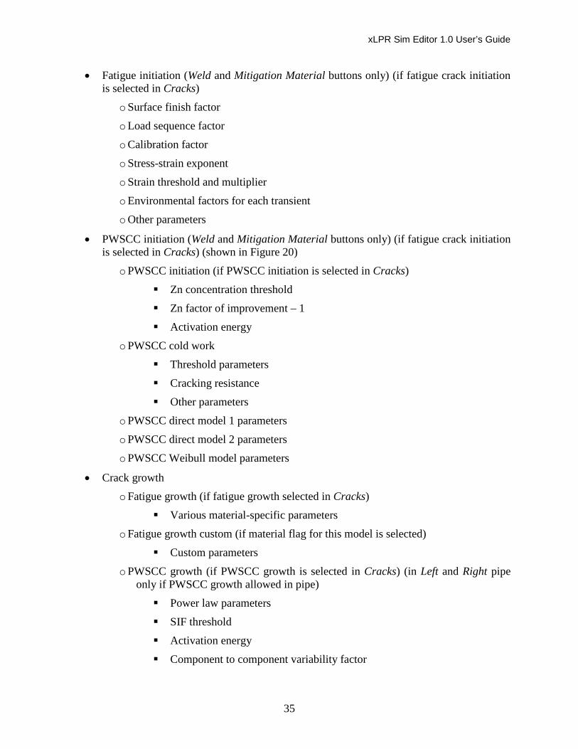
• PWSCC initiation (Weld and Mitigation Material buttons only) (if fatigue crack initiation is selected in Cracks) (shown in Figure 20)
o PWSCC initiation (if PWSCC initiation is selected in Cracks)
Zn concentration threshold
Zn factor of improvement – 1
Activation energy
o PWSCC cold work
Threshold parameters
Cracking resistance
Other parameters
o PWSCC direct model 1 parameters
o PWSCC direct model 2 parameters
o PWSCC Weibull model parameters
• Crack growth o Fatigue growth (if fatigue growth selected in Cracks)
Various material-specific parameters
o Fatigue growth custom (if material flag for this model is selected)
Custom parameters
o PWSCC growth (if PWSCC growth is selected in Cracks) (in Left and Right pipe only if PWSCC growth allowed in pipe)
Power law parameters
SIF threshold
Activation energy
Component to component variability factor
xLPR Sim Editor 1.0 User’s Guide
36
Within component variability factor
Peak to valley ECP ratio – 1
Characteristic width of peak versus ECP
Factor of improvement
Reference temperature
Figure 20. PWSCC Initiation panel for mitigation material.
4.4.2 Share Tab The Share tab has the following buttons:
• Submit Feedback This button is shown in Figure 21.
Figure 21. Share tab.
Submit Feedback – The Submit Feedback button provides a way to send feedback by email to the Sim Editor developers. Commonly, this feedback is to report a bug or to suggest an improvement. A window opens and lists three steps. For the first step the user enters a subject that identifies the feedback and enters a message to describe the issue. In step two, the user may include a capture of the current Sim Editor screen by checking the box and may edit the image by clicking a button. In step three, a button is provided to prepare the email using the user’s default email client.

xLPR Sim Editor 1.0 User’s Guide
37
4.4.3 Tools Tab The Tools tab has the following buttons:
• Screen Capture
• Options
• Edit Admin Password
• Run LEAPOR or TIFFANY These buttons are shown in Figure 22.
Figure 22. Tools tab.
Screen Capture – The Screen Capture button enables the user to capture a screen shot of the Sim Editor window at any time.
Unit Converter – This button produces a standalone window for converting values in one set of units to another set of units. Drop-down boxes are used to select units and unit types. A list of units allowed for xLPR is provided under the Help tab.
Importance Sampling List – This button is used to list all parameters in the Input Set where Importance Sampling is set to “Yes.”
Options – The Options button allows the user to set preferences for how the Sim Editor operates. An option here is whether to have the Sim Editor prompt the user before saving changes or for it to forgo the prompt and save changes automatically.
Edit Admin Password – The Edit Admin Password button allows a user with administrative privileges to change the administrator password.
Run LEAPOR or TIFFANY – The Run LEAPOR or TIFFANY button displays a popup window with instructions for running LEAPOR and TIFFANY and opens the Input Set in Microsoft Excel so that the user may execute the instructions provided in the popup window. The user should close the Excel file when done with this step.
4.4.4 Help Tab The Help tab has five buttons:
• Keyboard Shortcuts
• Entering Distributions
• Units
• About xLPR Sim Editor

xLPR Sim Editor 1.0 User’s Guide
38
• Submit Feedback These buttons are shown in Figure 23.
Figure 23. Help tab.
Keyboard Shortcuts – This button provides a list of keyboard shortcuts for the Sim Editor
Entering Distributions – The Entering Distributions button provides guidance and examples for entering certain log distributions consistent with GoldSim expectations. Specifically, this help button explains how to enter the following distributions:
• Log-Normal: Geometric Mean
• Log-Normal: True Mean
• Log-Uniform
Units – The Units button provides guidance on entering units consistent with GoldSim and xLPR expectations. A section of the GoldSim User’s Guide (GoldSim 2014) is provided by this button to explain the GoldSim units conventions. A unit converter tool is located under the Tools tab.
About xLPR Sim Editor – This button provides information on product version, Java, the software development team, technical support, copyright, system requirements, and 3rd party licenses.
Submit Feedback – The Submit Feedback button provides a way to send feedback by email to the Sim Editor developers. A description of this tool is provided in Section 4.4.2.
4.5 Database Mode Database mode opens by default to the Weld Type database as shown in Figure 24. The tabs in database mode are
• Get Started
• Weld Type Database
• Material Database
• Axial WRS Database
• Hoop WRS Database
• Share
• Tools
• Help

xLPR Sim Editor 1.0 User’s Guide
39
Figure 24. Database mode showing Weld Type database.
Each tab and database is discussed in the following subsections.
4.5.1 Get Started Tab Selecting the Get Started tab returns the user to the home page of the Sim Editor (Section 4.3).
4.5.2 Weld Type Database The Weld Type Database tab contains a collection of complete datasets to fill all of the parameters in the Properties tab of the Input Set, plant operation time (for synchronizing with EFPY), and flags from the User Options tab of the Input Set that control units in the Properties tab. The inputs under the Weld Type database tab include
• Weld type materials
• Plant operation period
• EFPY
• Geometry
• General operating conditions
• Normal operating loads and/or stresses for the various operating periods
• Earthquake inputs
xLPR Sim Editor 1.0 User’s Guide
40
• Mitigation options and inputs
• Crack initiation and growth (not specific to the material)
• Inspection and leak detection
• Correlations (not specific to the material) There are three sets of buttons in the ribbon of the Weld Type database tab:
• Weld Type (Section 4.5.2.1)
• Actions (Section 4.5.2.2)
• Weld Type Properties (Section 4.5.2.3)
4.5.2.1 Weld Type
As shown in Figure 24, only one button appears in the Weld Type ribbon: Weld Type Selector. Pressing this button allows the user to select the desired Weld Type dataset from the Weld Type database.
The name of the current dataset in the database is displayed in the top left of the panel space. In the example in Figure 24, it is Case 1.
Datasets may be Pre-Defined or User-Defined. Pre-Defined datasets may not be changed, created, or deleted without an administrator password. Section 4.5.2.2 explains how to generate User-Defined datasets from Pre-Defined datasets.
4.5.2.2 Actions
The buttons in the Actions ribbon are Edit, Save, New, Duplicate, Delete, and Search. They are shown in Figure 24.
Edit – To change database values, the Edit button must be selected. Until the Edit button is selected, inputs can only be viewed. Editing a Pre-Defined dataset requires an administrator password
Save – The Save button saves changes.
New – This button allows the user to begin a new dataset for the database selected. The new dataset begins with default values for all parameters and by default is set to User-Defined. The new dataset can be saved as Pre-Defined by toggling the Pre-Defined radio button at the top of the first panel. This button can only be successfully toggled by providing the administrator password. A unique name for the dataset is required.
Duplicate – This button allows the user to duplicate the current dataset and save it as a new dataset with a new name. The new dataset begins with values of the dataset duplicated. A unique name for the dataset is required. As in the case of the New button, the duplicate will default to User-Defined status but can be changed to Pre-Defined status with an administrator password.
Delete – This button allows the user to delete the current dataset. If the dataset is Pre-Defined, an administrator password is required.

xLPR Sim Editor 1.0 User’s Guide
41
Search – The Search button opens a pop-up window that can be used to search for a parameter or text string within the dataset or in the case of the Weld Type database, within the panels of the selected button in the Weld Type Properties set of buttons.
4.5.2.3 Weld Type Properties
The buttons of the Weld Type Properties ribbon are shown in Figure 24. They are the same buttons as the Global and Model Settings buttons in Section 4.4.1.2. However, there are several major differences from the simulation mode in the content. Differences include
• Only parameters from the Properties tab of the Input Set are included (plus plant operation period and five units flags).
• None of the parameters in the dataset are ever hidden because simulation options are for the most part not included in this database.
• Both constant (deterministic) and distribution fields are shown and editable for each parameter regardless of the Data Source value (constant, aleatory, or epistemic).
4.5.3 Material Database The Material Database tab contains a collection of complete datasets to fill all of the parameters in any one of the Material worksheets of the Input Set, i.e., Left Pipe, Right Pipe, Weld, or Mitigation. They include the same inputs that can be found under the Left Pipe, Right Pipe, Weld, and Mitigation Options buttons of the Material Properties set of buttons in the simulation mode of the Sim Editor. Part of the first input panel of the Materials database is shown in Figure 25.
Figure 25. Materials database.
As shown in Figure 25, input panels include
• Material name and material properties
• Fatigue properties needed by TIFFANY
• Crack initiation properties

xLPR Sim Editor 1.0 User’s Guide
42
• Crack growth properties
• Correlations between properties of the material There are two sets of buttons in the ribbon of the Material database tab:
• Material (Section 4.5.3.1)
• Actions (Section 4.5.3.2)
4.5.3.1 Material
One button appears in the Material ribbon: Material Selector. Pressing this button allows the user to select the desired Material dataset from the Material database.
The name of the current material dataset in the database is displayed in the top left of the input panel space.
Datasets may be Pre-Defined or User-Defined. Pre-Defined datasets may not be changed, created, or deleted without an administrator password.
Because this is a database, both constant (or deterministic) and distribution fields are shown and are editable for each parameter regardless of the Data Source value (constant, aleatory, or epistemic).
4.5.3.2 Actions
The buttons in the Actions ribbon are Edit, Save, New, Duplicate, Delete, and Search. These buttons are the same as those for the Weld Type database. Their use is described in Section 4.5.2.2.
4.5.4 Axial and Hoop WRS Databases The Axial WRS Database and Hoop WRS Database tabs contain collections of complete WRS tables in the Axial WRS and Hoop WRS worksheets of the Input Set. An example of the top portion of the input panel for an axial WRS profile is shown in Figure 26.
Figure 26. Axial WRS database.
Inputs include
• WRS name

xLPR Sim Editor 1.0 User’s Guide
43
• Correlation type
• Correlation coefficient
• Locations of WRS values (x/t)
• WRS values (nominal)
• Uncertainty parameters There are two sets of buttons in the ribbons of the Axial WRS database and Hoop WRS database tabs:
• Axial WRS or Hoop WRS (Section 4.5.4.1)
• Actions (Section 4.5.4.2)
4.5.4.1 Axial WRS or Hoop WRS
One button appears in the Axial WRS ribbon: Axial WRS Selector, and one button appears in the Hoop WRS ribbon: Hoop WRS Selector. Pressing this button allows the user to select the desired WRS dataset from the Axial WRS database or Hoop WRS database.
The name of the current WRS dataset in the database is displayed in the top left of the panel space. Datasets may be plotted by clicking the View Plot button.
Datasets may be Pre-Defined or User-Defined. Pre-Defined datasets may not be changed, created, or deleted without an administrator password.
4.5.4.2 Actions
The buttons in the Actions ribbon are Edit, Save, New, Duplicate, Delete, and Search. These buttons are the same as those for the Weld Type database. Their use is described in Section 4.5.2.2.
4.5.5 Share Tab This tab is identical to the tab described in Section 4.4.2.
4.5.6 Tools Tab This tab is identical to the tab described in Section 4.4.3 except that it does not include buttons for running LEAPOR or TIFFANY or for listing parameters marked for importance sampling.
4.5.7 Help Tab This tab is identical to the tab described in Section 4.4.4.

xLPR Sim Editor 1.0 User’s Guide
44
xLPR Sim Editor 1.0 User’s Guide
45
5 CONCLUSIONS This report is a user’s guide for the installation and use of xLPR Sim Editor 1.0. The xLPR Sim Editor is a graphical user interface for building and modifying the input file and input databases of the xLPR Version 2.0 probabilistic fracture mechanics software (xLPR-SDD-FW 2016). The Sim Editor provides a user-friendly way to identify inputs needed for an xLPR simulation, change simulation options and input values in an xLPR input file, and select and modify datasets from xLPR databases. Additional information on the various parameters in the xLPR input file and xLPR databases is provided in the xLPR user’s manual and other xLPR documents (xLPR-SDD-FW 2016; xLPR-UM-FW 2016).
Development of the xLPR Sim Editor 1.0 software and this user’s guide is not included within the xLPR quality assurance program. Input files and databases generated and modified by the Sim Editor may be easily inspected for correctness using Microsoft Excel.

xLPR Sim Editor 1.0 User’s Guide
46

xLPR Sim Editor 1.0 User’s Guide
47
6 REFERENCES GoldSim (2014). User's Guide GoldSim Probabilistic Simulation Environment. Version 11.1
(May 2014). GoldSim Technology Group LLC, Issaquah, Washington.
xLPR-SDD-FW (2016). xLPR Software Design Description for xLPR Framework. Version 3.0 (July 2016).
xLPR-UM-FW (2016). xLPR User’s Manual. Version 1.0 (August 2017).

xLPR Sim Editor 1.0 User’s Guide
48
DISTRIBUTION
1 David Rudland U.S. Office of Nuclear Regulatory Research Washington, DC 20555-0001 2 Matthew Homiack
U.S. Office of Nuclear Regulatory Research Washington, DC 20555-0001 3 Craig Harrington Electric Power Research Institute 3010 LBJ Freeway, Suite 300 Dallas, TX 75234 Send to: 1110 Cherrywood Drive, Cleburne, TX 76033
9 MS0747 Remi Dingreville 6232 1 MS0748 Patrick Mattie. Mgr 6232 1 MS0899 Technical Library 9536 (electronic only)