xl-grt60x series - asm.czdownload.asm.cz/inshop/prod/xtendlan/em-xl-grt60x.pdf · xtendlan...
TRANSCRIPT

1
XL-GRT60x series
G.SHDSL.BIS
VPN ROUTER
USER MANUAL
VERSION 1.00

2
1 INTRODUCTION ................................................................................................................................................. 1
1.1 DESCRIPTIONS ...................................................................................................................................................... 1
1.2 FEATURES .................................................................................................................................................................... 2
1.3 SPECIFICATIONS .................................................................................................................................................... 2
1.4 APPLICATIONS ...................................................................................................................................................... 6
1.4.1 VPN Access .................................................................................................................................................. 6
1.4.2 PPTP/ L2TP Access ....................................................................................................................................... 6
2 GETTING TO KNOW ABOUT THE VPN ROUTER ................................................................................................... 7
2.1 FRONT PANEL ...................................................................................................................................................................... 7
2.2 REAR PANEL......................................................................................................................................................................... 8
2.3 WAN PORT ................................................................................................................................................................. 9
2.4 LAN PORTS ....................................................................................................................................................... 11
2.5 CONSOLE PORT ..........................................................................................................................................................11
2.6 USB PORT ........................................................................................................................................................ 12
2.7 POWER CONNECTION .......................................................................................................................................... 12
2.8 RESET BUTTON ................................................................................................................................................... 12
2.9 PROTECTIVE EARTH (FRAME GROUND) TERMINAL ..................................................................................................... 13
3 CONFIGURATION ............................................................................................................................................. 14
3.1 CONFIGURATION METHODS .................................................................................................................................. 14
3.1.1 Installation ................................................................................................................................................ 14
3.1.2 Web Configuration .................................................................................................................................... 15
3.1.3 Serial Console Configuration ..................................................................................................................... 16
3.1.4 Telnet Configuration .................................................................................................................................. 17
3.2 LOGIN VIA WEB BROWSER .................................................................................................................................... 18
3.3 MENU TREE....................................................................................................................................................... 19
3.4 QUICK SETUP ..................................................................................................................................................... 26
3.4.1 System Mode ............................................................................................................................................ 26
3.4.2 SHDSL.bis mode ......................................................................................................................................... 29
3.4.3 LAN IP and Subnet Mask ........................................................................................................................... 30
3.4.4 WAN ENCAP .............................................................................................................................................. 30
3.4.5 WAN VPI/VIC ............................................................................................................................................. 30
3.4.6 Default Gateway ....................................................................................................................................... 31
3.4.7 DNS ........................................................................................................................................................... 31
3.4.8 Submit ....................................................................................................................................................... 32
3.5 NETWORK ......................................................................................................................................................... 34
3.5.1 SHDSL ........................................................................................................................................................ 34

3
3.5.2 Interfaces .................................................................................................................................................. 36
3.5.3 3.5G Backup .............................................................................................................................................. 39
3.5.4 DNS ........................................................................................................................................................... 40
3.5.5 DHCP ......................................................................................................................................................... 41
3.5.6 NAT ............................................................................................................................................................................................................. 44
3.6 ADVANCE .......................................................................................................................................................... 45
3.6.1 STP ............................................................................................................................................................ 45
3.6.2 VLAN ......................................................................................................................................................... 46
3.6.3 Static Route ............................................................................................................................................... 48
3.6.4 QoS ............................................................................................................................................................ 49
3.6.5 RIP ............................................................................................................................................................. 54
3.6.6 Virtual Server ............................................................................................................................................ 55
3.6.7 DMZ........................................................................................................................................................... 56
3.6.8 DDNS ......................................................................................................................................................... 57
3.6.9 IGMP ......................................................................................................................................................... 58
3.7 SECURITY .......................................................................................................................................................... 59
3.7.1 Firewall ...................................................................................................................................................... 59
3.7.2 VPN ........................................................................................................................................................... 60
3.7.3 Filter .......................................................................................................................................................... 67
3.8 MANAGEMENT .................................................................................................................................................. 71
3.8.1 SNTP .......................................................................................................................................................... 71
3.8.2 SNMP ........................................................................................................................................................ 73
3.8.3 TR-069 ....................................................................................................................................................... 76
3.8.4 UPnP .......................................................................................................................................................... 77
3.8.5 Sys Log....................................................................................................................................................... 78
3.8.6 Telnet ......................................................................................................................................................................... 78
3.8.7 SSH ............................................................................................................................................................ 79
3.8.8 Web ...................................................................................................................................................................79
3.9 SHOW .......................................................................................................................................................................81
3.9.1 Information ............................................................................................................................................... 81
3.9.2 Sys Log....................................................................................................................................................... 82
3.9.3 Script ......................................................................................................................................................... 82
3.10 STATUS .............................................................................................................................................................................. 83
3.10.1 SHDSL ................................................................................................................................................... 83
3.10.2 WAN ..................................................................................................................................................................... 84
3.10.3 Route Table ......................................................................................................................................................... 85
3.10.4 Interfaces.............................................................................................................................................. 85
3.11 UTILITIES ........................................................................................................................................................... 87
3.11.1 Upgrade................................................................................................................................................ 87

4
3.11.2 Config Tool........................................................................................................................................................... 88
3.11.3 Users ..................................................................................................................................................... 88
3.11.4 Ping ...................................................................................................................................................... 89
3.11.5 Trace Route ........................................................................................................................................... 90
APPENDIX A. TERMINOLOGY .............................................................................................................................. 92
APPENDIX B. FAQ ..................................................................................................................................................................... 100
B-1. 802.1Q TAG-BASED VLAN TEST CASES ............................................................................................................... 100
B-2. PORT-BASED VLAN .......................................................................................................................................... 106

1
XTENDLAN XL-GRT60x series G.SHDSL.bis VPN Router is a high performance 4-port Security Gateway
providing Internet access and LAN-to-LAN application over existing copper line for small/medium office.
Complying with the latest G.SHDSL.bis technology, ITU-T G.991.2 (2004) standard, XTENDLAN XL-GRT60x
series offer data transmission rates of up to 5.696Mbps in 2-wire mode, 11.392Mbps in 4-wire mode and
22.784Mbps in 8-wire mode.
XTENDLAN XL-GRT60x series VPN Router is integrated high-end Bridging/Routing capabilities with
advanced functions of Multi-DMZ, Virtual Server mapping, and VPN pass-through. Because of rapid growth of
network, virtual LAN has become one of the major new areas in internetworking industry. XTENDLAN
XL-GRT60x support port-based VLAN and IEEE 802.1q VLAN over ATM network.
With always on connection that DSL features, XTENDLAN XL-GRT60x series VPN routers provide
advanced firewall with Stateful Packet Inspection (SPI) and Denial of Service (DoS) protection, serving as
a powerful firewall to protect from outside intruders of secure connection. It also supports IP precedence to
classify and prioritize types of IP traffic. In additional, its VPN feature supports data transmission over the
Internet by data encryption/decryption between two sites. VPNs feature allows replacing a private leased line
to minimize the expense among global inter-connection.
Not only the much higher bandwidth than convention symmetric digital subscriber loop, XTENDLAN XL-
GRT60x series also provide the network administrators tool of Quality of Service (QoS) to allocate network
resources effectively. By classify the priority of services, the functions of bandwidth management increases
efficiency and productivity on specific demands such as VoIP, video streaming, video-conferencing or
interactive game applications to guarantee all the application get the deserved service quality.
1 Introduction
1.1 Descriptions

2
Easy configuration and management with password control for various application environments
Efficient IP routing and transparent learning bridge to support Internet broadband services
Virtual LANs (VLANs) offer significant benefit in terms of efficient use of bandwidth, flexibility,
performance and security
VPN for safeguarded connections
Built-in advanced SPI firewall
IP precedence to partition the traffic into multiple classes of service
Four 10/100M Base-T Auto-sensing, Auto-negotiation and Auto-MDI/MDIX switching port for flexible
local area network connectivity
USB ports for 3.5G USB dangle modem for Internet access backup(For USB models only)
Fully ATM protocol stack implementation over SHDSL.bis
PPPoA and PPPoE support user authentication with PAP/CHAP/MS-CHAP/MS-CHAPv2
SNMP management with SNMPv1/v2c/v3 agent and MIB II
Getting enhancements and new features via Internet software upgrade
Hardware Interface
WAN Port:
SHDSL.bis: ITU-T G.991.2 (2004) Annex A/B/F/G supported
Encoding scheme: TC-PAM 16/ TC-PAM 32
Data Rate: N x 64kbps (N= 3 ~ 89, 89 as default) (For XL-GRT602)
Data Rate: N x 128kbps (N= 3 ~ 89, 89 as default) (For XL-GRT604)
Data Rate: N x 256kbps (N= 3 ~ 89, 89 as default) (For XL-GRT608)
Impedance: 135 ohms
LAN Port: 4-Ports 10/100M Switch supports
Auto-negotiation for 10/100Base-TX and Half/Full Duplex
Auto-MDIX
USB Port: 2-ports USB
USB 2.0
Serial Console Port: RJ45 connector
Factory Default Reset: Push Button
LED:
Power (Green)
WAN LINK/ACT(Green), one LED per pair
LAN (Port 1~port 4) LINK/ACT (Green)
1.2 Features
1.3 Specifications

3
ALARM (Red)
Bridging and VLAN
IEEE 802.1D Transparent Learning Bridge
IEEE 802.1Q and Port Based VLAN
Spanning Tree Protocol (STP)
Up to 2K Mac Address
Routing
Static routing and RIP v1/v2(RFC 1058/2453)
NAT/PAT (RFC1631)
NAT Application Level Gateways
Skype/MSN/Yahoo Messenger (RFC2933)
VoIP(SIP) pass through
VPN PPTP/L2TP pass through
Virtual Server
Network Protocol
IPv4 (ARP/RARP, TCP/UDP,ICMP)
DHCP Client/Server, Relay
DNS Relay/Proxy, Dynamic DNS(DDNS)
IGMP v1/v2/v3, IGMP Proxy, IGMP Snooping
SNTP and UPnP
ATM
8 PVC
OAM F4/F5 Loopback
AAL5
VC Multiplexing and SNAP/LLC
Ethernet over ATM (RFC 2684/RFC1483)
Multiple protocol over ATM AAL5(MPOA, REF1483/2684)
PPP over ATM (RFC 2364)
Classic IP over ATM (RFC 1577)
QoS(UBR/CBR/VBR/VBR-RT)
PPP
PPPoE
PAP/CHAP/MS-CHAP/MS-CHAPv2
Configurable timer to auto-reconnect,

4
Configurable Idle times for timeout
QoS
802.1P Tag
IPv4 TOS/DiffServ
Class-based Prioritization
Class-based Traffic Shaping
Class-based DSCP Mark
Up to 8 priority queues
IP Precedence Alternation
VPN
IPSec (RFC2411) up to 4 Tunnels
DES/3DES/AES
MD5/SHA-1
IKE/Manual Key
ISAKMP (RFC 2407/2408/4306)
IKE v1 (RFC 2409/4109)
PSK
L2TP/PPTP
Firewall
SPI (Stateful Packet Inspection)
Intrusion Detection/DoS (Denial of Service)
DMZ
Content Filtering
URL Blocking
Packet Filtering/Access Control List (ACL)

5
Management
Web and Telnet management via LAN ports
CLI via serial console port
Support SSH (RFC4250/4251/4252/4253/4254/4255/4256)
SNMP v1/v2c/v3 (RFC 1157/1901//1905)
MIB II (RFC 1213/1493)
Syslog with Remote Logging support
Firmware Upgrade via TFTP
Configuration Data Import/Export
Multiple Levels of Administration Privilege
Support TR-069 WAN management protocol
Physical / Electrical
Dimensions: 18.7 x 3.3 x 14.5cm (WxHxD)
Power: 100~240VAC (via power adapter)
Power Consumption: 9 watts Max
Temperature: 0~45ºC
Humidity: 0%~95%RH (non-condensing)
Model Number list:
Model Number
Specification
XL-GRT602
XL-GRT604
XL-GRT608
Maximum DSL wires 2-wires 4 -wires 8-wires
Maximum data rate
5.696 Mbps
11.392 Mbps
22.784
Mbps
USB port
USB port for 3.5G Dongle Modem with
Internet access backup

6
1.4 Applications
1.4.1 VPN Access
1.4.2 PPTP/ L2TP Access

7
LED status of VPN Router:
LEDs Active Description
PWR On The power adaptor is connected to this device
DSL
LINK 1
On SHDSL.bis line 1 connection is established
Blink
SHDSL.bis line 1 handshake
Transmit or received data over SHDSL.bis link 1
LINK 2
On SHDSL.bis line 2 connection is established
Blink
SHDSL.bis line 2 handshake
Transmit or received data over SHDSL.bis link 2
LINK 3
On SHDSL.bis line 3 connection is established
Blink
SHDSL.bis line 3 handshake
Transmit or received data over SHDSL.bis link 3
LINK 4
On SHDSL.bis line 4 connection is established
Blink
SHDSL.bis line 4 handshake
Transmit or received data over SHDSL.bis link 4
LAN
LINK/ACT1
On Ethernet cable is connected to LAN 1
Blink Transmit or received data over LAN 1
LINK/ACT2
On Ethernet cable is connected to LAN 2
Blink Transmit or received data over LAN 2
LINK/ACT3
On Ethernet cable is connected to LAN 3
Blink Transmit or received data over LAN 3
LINK/ACT4
On Ethernet cable is connected to LAN 4
Blink Transmit or received data over LAN 4
On SHDSL.bis line connection is dropped
ALM Blink SHDSL.bis self test
Off No Alarm
2 Getting to know about the VPN Router
2.1 Front Panel

8
Connector Description
DC-IN Power adaptor inlet: Input voltage from 9V to 12VDC
CONSOLE RJ-45 for system configuration and maintenance
RST Reset button for reboot or load factory default
LAN (1,2,3,4) 10/100BaseT auto-sensing and auto-MDIX for LAN port (RJ-45)
USB USB ports
DSL G.SHDSL .Bis interface for WAN port (RJ-45)
Frame Ground / Protective earth
2.2 Rear Panel

9
The VPN Router have one port for WAN port connection, this is a G.SHDSL .Bis interface.
The pin assignments for SHDSL line cable are:
For 2-wire (one pair) model , Loop1 has been used.
For 4-wire (two pair) model, Loop1 and 2 have been used.
For 8-wire (four pair)model, Loop1, 2, 3 and 4 have been used.
Channel A Channel B Channel C Channel D
2-wire model (XL-GRT602)
2-wire mode Loop1 (4,5)
4-wire model (XL-GRT604)
2-wire mode
4-wire mode
Loop1 (4,5)
Loop1 (4,5) Loop2 (3,6)
8-wire model (XL-GRT608)
2-wire mode
4-wire mode
8-wire mode
Loop1 (4,5)
Loop1 (4,5) Loop2 (3,6)
Loop1 (4,5) Loop3 (1,2) Loop4 (7,8) Loop2 (3,6)
For test on point to point connection purpose, you can use the Straight-Through Ethernet Cable for
SHDSL.bis link as the following.
2.3 WAN Port

10
T-568A Straight-Through Ethernet Cable
T-568B Straight-Through Ethernet Cable
Both the T-568A and the T-568B standard Straight-Through cables are been used.

11
The VPN Router have four LAN ports. Those ports are auto-negotiating, auto-crossover. In 10/100Mbps
Fast Ethernet, the speed can be 10Mbps or 100Mbps and the duplex mode can be half duplex or duplex.
The auto-negotiating ports can detect and adjust to the optimum Ethernet speed (10/100 Mbps) and duplex
mode (full duplex or half duplex) of the connected device. The auto-crossover (auto-MDI/MDI-X) ports
automatically works with a straight-through or crossover Ethernet cable.
Connect the RJ-45 jack of the console cable to the console port of the VPN Router. Connect the DB-9
female end to a serial port( COM1 , COM2 or other COM port) of your computer.
The wiring diagram of console cable is as following:
2.4 LAN ports
2.5 Console Port

12
The pin assignment of RJ-45 modular jack on the Console cable:
Pin Number Abbrev. Description Figure
1 DSR DCE ready
1 8
1 8
Front View
Top View
2 DCD Received Line Signal Detector
3 DTR DTE ready
4 GND Signal Ground
5 RXD Received Data
6 TXD Transmitted Data
7 CTS Clear to Send
8 RTS Request to Send
Only for with USB ports models. This is using for connection of 3G/3.5G USB modem.
Make sure you are using the correct power source as the AC/DC adaptor. Inset the female end of power
adaptor’s cord into the power receptacle on the rear panel. Connect the power adaptor to an appropriate
power source.
The reset button can be used only in one of two ways.
(1) Press the Reset Button for two second will cause system reboot.
(2) Pressing the Reset Button for eight seconds will cause the product loading the factory default setting
and losing all of yours configuration. When you want to change its configuration but forget the user name or
password, or if the product is having problems connecting to the Internet and you want to configure it again
clearing all configurations, press the Reset Button for eight seconds with a paper clip or sharp pencil.
2.6 USB Port
2.7 Power connection
2.8 Reset Button

13
The marked lug or terminal should be connected to the building protective earth bus. The function of
protective earth does not serve the purpose of providing protection against electrical shock, but instead
enhances surge suppression on the DSL lines for installations where suitable bonding facilities exist. The
connector type is M3 machine screw.
2.9 Protective Earth (Frame Ground) terminal

14
!
There are three methods to configure the VPN Router: serial console, Telnet and Web Browser. Users
have to choose one method to configure the VPN Router.
This following guide is designed to lead users through Web Configuration of G.shdsl.bis VPN Router in the
easiest and quickest way possible. Please follow the instructions carefully.
Step 1. Connect the power adapter to the port labeled “DC-IN” on the rear panel of the VPN Router.
Step 2. Connect the Ethernet cable to LAN ports. (Note: The VPN Router supports auto-MDIX switching
hub so both straight through and cross-over Ethernet cables can be used.)
Step 3. Connect the phone cable to the VPN Router and the other side of phone cable to wall jack.
Step 4. Connect the power adapter to power source.
Step 5. Turn on the PC or NB, which is used for configuration the VPN Router.
To avoid possible damage to this VPN Router, DO NOT turn on this device before Hardware
Installation.
3 Configuration
3.1 Configuration Methods
3.1.1 Installation

15
Connection with VPN Router
Make sure that Ethernet Adapter had been installed in PC or NB used for configuration of the modem.
TCP/IP protocol is necessary for web configuration, so please check the TCP/IP protocol whether it has been
installed.
The VPN Router provides a browser interface that allows you to configure and manage this device. After
you set up your IP address for the VPN Router, you can access the VPN Router’s Web interface applications
directly in your browser by entering the IP address of the VPN Router. You can then use your Web browser
to list and manage configuration parameters from PC.
Web Configuration requires Internet Explorer 5.0 or later or Netscape Navigator 6.0 and later versions. The
recommended screen resolution is 1024 by 768 pixels.
3.1.2 Web Configuration
16
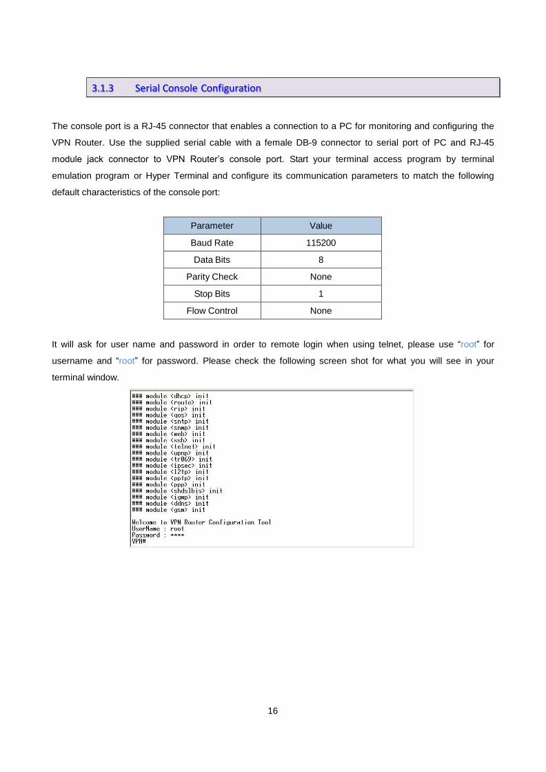
The console port is a RJ-45 connector that enables a connection to a PC for monitoring and configuring the
VPN Router. Use the supplied serial cable with a female DB-9 connector to serial port of PC and RJ-45
module jack connector to VPN Router’s console port. Start your terminal access program by terminal
emulation program or Hyper Terminal and configure its communication parameters to match the following
default characteristics of the console port:
Parameter Value
Baud Rate 115200
Data Bits 8
Parity Check None
Stop Bits 1
Flow Control None
It will ask for user name and password in order to remote login when using telnet, please use “root” for
username and “root” for password. Please check the following screen shot for what you will see in your
terminal window.
3.1.3 Serial Console Configuration

17
The VPN Router also supports telnet for remote management. Please make sure the correct Ethernet cable
connected the LAN ports of device to your computer. The LAN indicator on the front panel shall light on if a
correct cable is used. Start your telnet client with a command window or VT100 terminal emulation by key in
“192.168.0.1”, which is the management IP address of XtendLan XL-GRT60x series VPN router, and wait
for the login page prompts up. Then, key in the user name and the password once the login page shows.
The login page is shown as the following screen shot. (The default user name and password are “root”
and “root”.)
All display screens are as same as serial console configuration. The default IP address is “192.168.0.1” and
you can customerize the IP address for you application. In addition, the default Telnet function is disable.
Therefore, before using this Telnet function, please enable Telnet with using Web management .
3.1.4 Telnet Configuration

18
This section introduces the configuration and functions of the web-based management. It is an HTML-based
management interface that allows users to setup and manage XtendLan XL-GRT60x VPN routers. This
configuration system offers all monitoring and management features which allow users to access VPN routers
from anywhere on the network with a standard browser, such as, Internet Explorer or Firefox.
Step 1. User can use any common browsers, such as, Internet Explorer, on your computer to connect the
VPN Router. Then, please type “http://192.168.0.1” in the address bar of the browser you just
open.
Step 2. The default IP address and sub net-mask of the management port of VPN Router are “192.168.0.1”
and “255.255.255.0”.
Step 3. If DHCP function is Disable, your computer can set the same net-mask such as 192.168.0.X which
X is from 2 to 254, so you are able to connect to the VPN router.
Step 4. Key in user name, “root”, and password, “root”; then, click on “Login” button to login the web
configuration.
Note: Both the default user name and password are “root”. It is suggested to change the user name and the
password for security reason.
Note: For safety purpose, the password will be prompt as star symbol.
Note: Once you change the user name and password, please login with the new user name and password in
the next login process.
3.2 Login via Web Browser
19
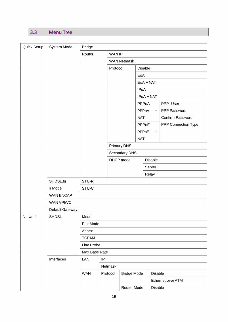
Quick Setup System Mode Bridge
Router WAN IP
WAN Netmask
Protocol Disable
EoA
EoA + NAT
IPoA
IPoA + NAT
PPPoA PPP User
PPP Password
Confirm Password
PPP Connection Type
PPPoA +
NAT
PPPoE
PPPoE +
NAT
Primary DNS
Secondary DNS
DHCP mode Disable
Server
Relay
SHDSL.bi
s Mode
STU-R
STU-C
WAN ENCAP
WAN VPI/VCI
Default Gateway
Network SHDSL Mode
Pair Mode
Annex
TCPAM
Line Probe
Max Base Rate
Interfaces LAN IP
Netmask
WAN Protocol Bridge Mode Disable
Ethernet over ATM
Router Mode Disable
3.3 Menu Tree

20
IPoA
PPPoA PPP User, PPP
Password, PPP
Connection type
PPPoE
ENCAP
VPI-VCI
QoS Class
QoS PCR
QoS SCR
Gateway
3.5G Backup Mode
Location
ISP
Manufacture
Dial Number
APN
Keep-alive Interval
Keep-alive Server
DNS Primary
Secondary
DHCP Mode Disable
Server
Relay
DHCP Server Mode
Subnet
Netmask
IP Range
Gateway
DNS
Lease Time
DHCP Relay IP
Interface
NAT Mode
Entry (1~16) Enable
Source IP
Source Netmask
Output Interface
Advance STP Router Mode Not available
21
Bridge Mode Mode
Aging Time
VLAN Router Mode Not available
Bridge Mode Mode Disable
802.1Q Tag-Based VLAN
Port-Based VLAN
Static Route Destination
Netmask
Gateway
Interface
QoS Mode
Traffic Classify Mode
Class ID
Protocol
Src IP
Src Netmask
Src Port
Dst IP
Dst Netmask
Dst Port
802.1P Class ID
IP DSCP DSCP
Class ID
Class Shaping Mark Mode
DSCP
TOS
Min Rate
Max Rate
RIP Mode
RIP Version
LAN Mode
Passive
WAN1~WAN8 Mode
Passive
Virtual Server Router Mode Mode
Entry (1~16) Enable
Description
Interface

22
Protocol
Public Port
Private IP/Port
Bridge Mode Not available
DMZ Router Mode Mode
WAN I/F
Host IP
Bridge Mode Not available
DDNS Mode
Provider
Host Name
User Name
Password
IGMP IGMP Proxy / Snooping
Security Firewall Router Mode Mode
Bridge Mode Not available
VPN Router Mode IPSEC Mode
Name
WAN
Perfect Forward Secrecy
Local Subnet
Local Netmask
Remote Public IP
Remote Local LAN Subnet
Remote Local LAN Netmask
Pre-shared Key
L2TP Mode
Authentication
Virtual IP
L2TP/IPSec Mode
IPSec Interface
IPSec PSK
User
PPTP Mode
Authentication
Virtual IP
User
Bridge Mode Not available

23
Filter IP Filter Mode
Default Policy
Entry(1~16) Mode
Action
Protocol
Source IP/ Mask
Source Start/ End Port
Destination IP/ Mask
Destination Start/ End Port
MAC Filter Mode
Default Policy
Entry(1~16) Mode
MAC
Action
Management SNTP Sync With PC
SNTP Mode
Time Server
Time Zone
SNMP SNMPv3 Mode
V3 User Name
V3 Auth. Password
V3 Priv. Password
V3 Auth. Mode
V3 Auth. Type
V3 Priv. Type
V3 Access
Trap Mode
Community
Trap Host IP
TR069 Mode
ACS URL
ACS Username
ACS Password
Periodic Inform Enable
Periodic Inform Interval
Periodic Inform Time
Connection Request IP
Connection Request Port

24
Connection Request Username
Connection Request Password
Retry Times
UPnP Mode
Sys Log Remote Server Mode
Remote Server Address
Remote Server Port
Telnet Mode
Port
SSH Mode
Port
Web Refresh Time
Service Port
Show Information Hardware MCSV
Software MCSV
Software Version
DSL Chip Name
DSL Phy Firmware Version
DSL IDC Firmware Version
MAC
Serial No
Present Time
System Uptime
Sys Log
Script
Status SHDSL
WAN
Route Table
Interfaces
STP (not available in router mode)
Utilities Upgrade
Config Tool Default
Backup
Restore
Users User 1~4 Name
Level
Password
Confirm

25
Ping IP Address
Size
Count
Update
Trace Route Host name or IP
Packet Datagram
Update Interval

26
“Quick Setup” function guides users to setup their VPN routers step by step. This VPN Router can be set as
a bridge or a router. The following sections show how to setup a bridge mode or a router mode.
“System Mode” allows users to decide this VPN router should be a bridge device or a router device.
“Router mode” is when the DSL modem performs all the functions that allow you to connect to the Internet which include: all the technical settings (VCI, encapsulation, etc.) and the VPN router also connects to the ISP with your username and password. You can basically just connect to your computer.
“Bridge mode”, on the other hand, allows some external device, for example, your computer or a separate router, to do the ISP connection, etc. In bridge mode, all the VPN router does is remembering your VCI, VPI and encapsulation settings. The ISP information and IP address assigned is controlled b your separate router or computer in PPP mode.
Click on “Bridge” to set this VPN router as a bridge device.
3.4 Quick Setup
3.4.1 System Mode
3.4.1.1 Bridge Mode

27
Click on “Router” to assign this VPN router to be a router device.
Once “System Mode” is set to “Router”, more setups will be shown as the screen shot above.
WAN Section
Fill up WAN port information for the VPN router as the router mode.
1. WAN IP and WAN Netmask
Fill up the IP address and the netmask of WAN.
3.4.1.2 Router Mode

28
2. Protocol
Nine options are available for this setup:
Disable: if protocol is “Disable”, WAN will be closed; hence, the information of WAN IP and WAN
Netmask will not be effective.
EoA
EoA + NAT
IPoA
IPoA + NAT
PPPoA
PPPoA + NAT
PPPoE
PPPoE + NAT
DHCP Mode
Choose whether DHCP mode should be “Disable”, “Server” or “Relay”.
PPP Protocol
This section is only available when the protocol is “PPPoA”, “PPPoA + NAT”, “PPPoE”, or “PPPoE + NAT”.
29
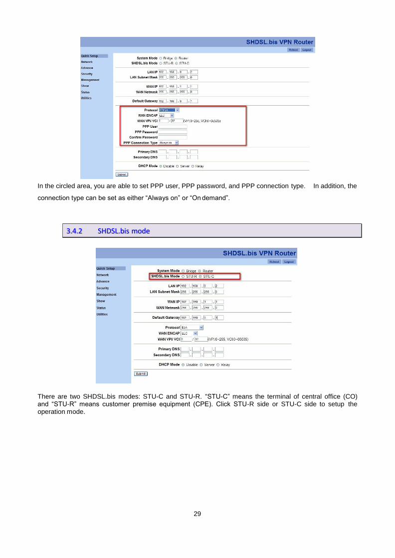
In the circled area, you are able to set PPP user, PPP password, and PPP connection type. In addition, the
connection type can be set as either “Always on” or “On demand”.
There are two SHDSL.bis modes: STU-C and STU-R. “STU-C” means the terminal of central office (CO) and “STU-R” means customer premise equipment (CPE). Click STU-R side or STU-C side to setup the operation mode.
3.4.2 SHDSL.bis mode
30
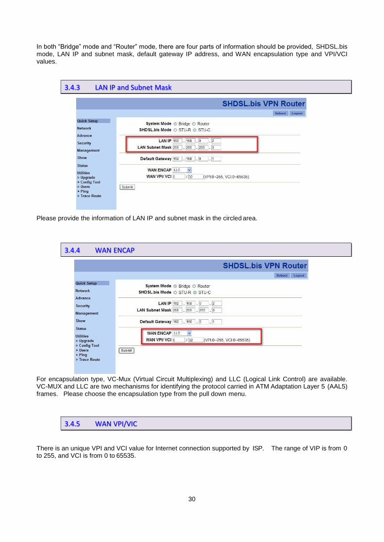
In both “Bridge” mode and “Router” mode, there are four parts of information should be provided, SHDSL.bis mode, LAN IP and subnet mask, default gateway IP address, and WAN encapsulation type and VPI/VCI values.
Please provide the information of LAN IP and subnet mask in the circled area.
For encapsulation type, VC-Mux (Virtual Circuit Multiplexing) and LLC (Logical Link Control) are available. VC-MUX and LLC are two mechanisms for identifying the protocol carried in ATM Adaptation Layer 5 (AAL5) frames. Please choose the encapsulation type from the pull down menu.
There is an unique VPI and VCI value for Internet connection supported by ISP. The range of VIP is from 0 to 255, and VCI is from 0 to 65535.
3.4.3 LAN IP and Subnet Mask
3.4.4 WAN ENCAP
3.4.5 WAN VPI/VIC

31
In quick setup process, fill up the default gateway IP address.
Two sets of DNS addresses can be stored in DNS section, primary DNS and secondary DNS.
3.4.6 Default Gateway
3.4.7 DNS

32
Click on “Submit” button to save all settings. After saving all settings, the following screen shots will be
shown to confirm the configurations.
For bridge mode
For router mode

33
Click on “Apply” to activate these configurations. The VPN router will be rebooted as the following screen
shot.

34
Network section allows users to setup the following functions.
1. SHDSL
2. Interfaces
3. 3.5G Backup
4. DNS
5. DHCP
6. NAT
Please check the sections for detail information on how to use these functions.
“SHDSL” function allows you to change SHDSL parameters.
1. Mode:
You are able to change your VPN router’s mode to STU-R or STU-C in here.
2. Pair Mode
For “Pair Mode” parameter, you are able to choose how many wire you would like to use on SHDSL.bis
connection.
The table above indicates the model number and its corresponding available wire numbers. For
3.5 Network
3.5.1 SHDSL
Line Type Mode
VPN Router
2-wire
(1
pair)
4-wire
(2 pair)
8-wire
(4 pair)
XL-GRT602 ●
XL-GRT604 ● ●
XL-GRT608 ● ● ●

35
example:
XL-GRT602 (2-wire model) can select 2-wire line type only.
XL-GRT604 (4-wire model) can select 2-wire and 4-wire line types.
XL-GRT608 (8-wire model) can select 2-wire, 4-wire or 8-wire line types.
3. Annex
There are four Annex types, Annex A, Annex B, Annex A/F and Annex B/G. Please confirm with your
ISP.
4. TCPAM
Three possibilities are available for TCPAM feature, “Auto”, “TCPAM-16” and “TCPAM-32”. “Auto”
means the system will choose TCPAM automatically and this option is only available when the Annex type
is “Annex A/F” or “Annex B/G”.
5. Line Probe
You are able to choose to disable or enable “Line Probe” function for data rate adpative mode. When
“Line Probe” function is enabled, the system will search on the best connection based on the value of
“Max Base Rate” automatically.
6. Max Base Rate
This value will be used for “Line Probe” in order to find the best connection when line probe function is
enabled. In addition, the value range is differed according to Annex type.
SHDSL.bis
VPN Router
Annex A
Annex B
Annex A/F
Annex B/G
Range 3 ~ 36 3 ~ 36 3 ~ 89 3 ~ 89
SHDSL.bis VPN
Router
Annex A
Annex B
Annex A/F
Annex B/G
Auto ● ●
TCPAM-16 ● ● ● ●
TCPAM-32 ● ●

36
“Interfaces” function provides a tool to change LAN settings, WAN settings, and the default gateway after the
initial setups were completed. Please remember to reboot your VPN router after any changes are made.
You are able to change LAN configurations in “Interfaces” function. Once you change the settings, please
click on “Submit” to save the modification.
The VPN Router supports 8 VCs (virtual circuit) for WAN. Click on the number to configure each VC.
3.5.2 Interfaces
3.5.2.1 LAN
3.5.2.2 WAN

37
The screen shot above will be shown once you select a VC to configure. Fill up IP address, subnet mask,
gateway, encapsulation type, and VPI/VCI information. Then, setup QoS class (UBR, CBR, VBR-RT and
VBR-NRT), QoS PCR (Peak Cell Rate), and QoS SCR (Substained Cell Rate) information.
For Bridge mode, “Protocol” provides two options, “Disable” or “Ethernet over ATM”.
However, for Router mode, there are four options in “Protocol” menu, “Disable”, “IPoA”, “PPPoA” or “PPPoE”.

38
If you choose “PPPoA” or “PPPoE” type for protocol parameter, four more information fields will be needed.
Default gateway information can be changed in “Interfaces” section.
3.5.2.3 Default Gateway

39
“3.5G Backup” function. VPN Router with USB models support automatic backup function. When
connecting with SHDSL.bis, it will enable the 3G/3.5G broadband connection automatically when SHDSL.bis
Internet connection is not available. You can surf the Internet anywhere and anytime via this device.
If you would love to connect with a 3G/3.5G modem card or a SIM card, please follow the following
instructions.
Step 1. Connect power adapter to VPN router.
Step 2. Connect another Ethernet cable from the any LAN ports (1~4) on VPN router to the Ethernet
socket on the PC.
Step 3. Insert SIM card into 3G/3.5G modem card, and connect the modem card with one of USB ports of
VPN router.
XtendLan XL-GRT60x VPN Router will recognize a 3G/3.5G modem card or SIM card automatically when a
3G/3.5G device is connected to one of VPN Router’s USB ports. No additional setup procedure is required.
Only one Internet connection (either 3G/3.5G wireless or DSL wired) can be used at the same time. The
primary connection method is DSL wired Internet; in the other hand, 3G/3.5G wireless connection is the
backup way.
PIN code or user name / password required
Please check the authentication method you want to use. Most of telecomm service providers require you to
3.5.3 3.5G Backup
3.5.3.1 3G/3.5G Modem card installation
3.5.3.2 3G/3.5G Internet Configuration
40
input Dial Number and APN (Access Point Name), please those items provided by telecomm service provider.
After finish type those items, then click ‘APPLY’ button.
Note: Different ISP’s require Dial Number and APN for connecting to the Internet, please check with your ISP
as to the type of connection it requires.
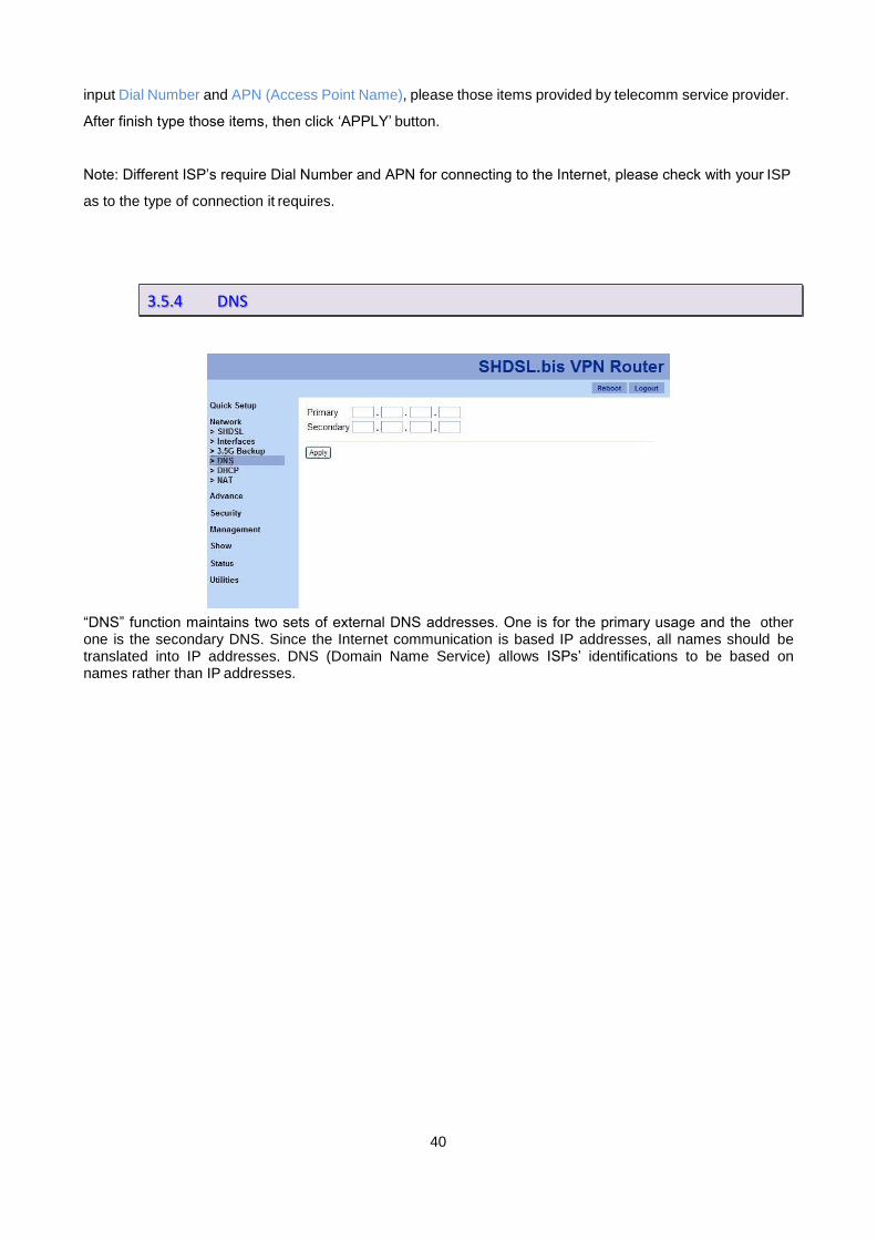
“DNS” function maintains two sets of external DNS addresses. One is for the primary usage and the other one is the secondary DNS. Since the Internet communication is based IP addresses, all names should be translated into IP addresses. DNS (Domain Name Service) allows ISPs’ identifications to be based on names rather than IP addresses.
3.5.4 DNS

41
DHCP (Dynamic Host Configuration Protocol) is a communication protocol that allows network administrators
to manage centrally and assigns IP addresses in an organization's network automatically.
“DHCP” feature provides three DHCP modes: “Disable”, “Server” and “Relay”.
1. Disable: Disable DHCP Server.
2. Server: Enable DHCP Server and assign IP addresses.
3. Relay: Enable DHCP Server and pass through original IP addresses.
3.5.5 DHCP
3.5.5.1 Mode

42
First, please make sure you set “Mode” to “Server”. Then, choose a DHCP server (there are five DHCP servers available in this configuration system.) and configure its details by click on the number. The following screen shot is the detail setups of a DHCP server.
3.5.5.2 DHCP Server

43
Please make sure choose “Relay” mode first. Then, please provide the information of DHCP server IP address and assign a WAN port.
3.5.5.3 DHCP Relay

44
NAT (Network Address Translation) is a set of rules for translating an intranet IP address, such as, a company
network, to a public IP address. Note: NAT is only available in “Router” mode.
First, you need to choose whether you want to enable or disable NAT.
Then, if you want to enable NAT and click on “Enable” button of “Mode” section. Please configure the circled
section in the following screen shot.
There are sixteen NAT rules can be stored in XL-GRT60x VPN router configuration system at the same time.
By providing the information of IP and netmask, you are able to setup an IP group, and then, assign this
group to an output WAN port. If you would love to activate one NAT rule, please check on the particular
checkbox and click on “Apply” to issue the modification.
3.5.6 NAT

45
“Advance” menu provides nine functions:
1. STP
2. VLAN
3. Static Route
4. QoS
5. RIP
6. Virtual Server
7. DMZ
8. DDNS
9. IGMP
Note: The advanced functions are only for advanced users to setup advanced functions. The incorrect
setting of advanced function will affect the performance or system error, even disconnection.
STP (Spanning-Tree Protocol) defined in the IEEE 802.1D, is a link management protocol that provides path
redundancy while preventing undesirable loops in the network. For an Ethernet network to function properly,
only one active path can exist between two stations.
Click on “Disable” or “Enable” to setup STP mode. “Aging Time” is for how long you would like to refresh the
mapping of IP address and MAC address. The default aging time is 300 seconds.
Note: STP is only available in “Bridge” mode.
3.6 Advance
3.6.1 STP

46
VLAN (Virtual Local Area Network) allows a physical network to be partitioned into multiple logical networks.
Devices on a logical network belong to one group. A device can belong to more than one group. With
VLAN, a device cannot directly talk to or hear from devices that are not in the same group. When properly
configured, VLAN prevents one subscriber from accessing the network resources of another on the same
LAN. In addition, VLAN also increases network performance by limiting broadcasts to a smaller and more
manageable logical broadcast domain.
Note: VLAN function is only available in “Bridge” mode.
Users can choose three VLAN modes: “Disable”, “802.1Q Tag-Based VLAN” and “Port-Based VLAN”.
Click on “Disable” setup the mode and click on “Apply” to change the VPN router’s VLAN mode.
3.6.2 VLAN

47
Click on “802.1Q Tag-Based VLAN” to show more configuration as the following screen shot.
Assign each group’s VID and which port should be in a group. Then, assign PVID to the port you need and
its link type, un-tag or tag. Then, click on “Apply” to set your VPN router with 802.1Q Tag-Based VLAN
policy.
Click on “Port-Based VLAN” in the mode section and you will see the following configuration section as the
screen shot below.
Assign which port should be in one group together by click on the corresponding radio buttons in each entry.
Click on “Apply” to save this changes.
3.6.2.1 802.1Q Tag-Based VLAN
3.6.2.2 Port-Based VLAN

48
“Static route” is a path in the router that indicates how it will reach a certain subnet by taking a specific path.
A static route is one that is manually installed by your network administrator.
Static routes have advantages and disadvantages as compares to dynamic routes.
Advantages of Static Routes
Static routes are easier to configure
No need for overhead on the routing protocol
As long as you have a tight IP mask, this offers you reliable security
Disadvantages of Static Routes
In order to make changes in the network, you have to manually configure the route
When network outage is experienced, it does not automatically route around
Although this is quite easy to configure, it might not work for large and complicated networks
It is important that any network administrator have substantial knowledge about static routes. Although this
type of route may not be as effective with large networks, they are quite useful in any size of networks.
Meanwhile, even if you have setup a dynamic route, there are cases that still require a static route.
3.6.3 Static Route

49
QoS(Quality of Service) refers to both a network’s ability to deliver data with minimum delay, and the
networking methods used to control the use of bandwidth. Without QoS, all traffic date is equally likely to be
dropped when the network is congested. This can cause a reduction in network performance and mark the
network inadequate for time-critical application such as video-on-demand. QoS is to decide the priorities to
pass though VPN Router according to your settings once if the bandwidth is exhausted or fully saturated.
First of all, you need to decide whether you want to enable QoS policy or disable it. Only when the mode is
set to “Enable”, the following policies will work.
3.6.4 QoS
3.6.4.1 Mode

50
Click on the number to configure each entry’s details.
3.6.4.2 Traffic Classify

51
Click on “802.1P” tag and show the screen shot above. Click on the number of an entry to configure a
queue’s class ID.
User priority is giving eight ( 23 = 8 ) priority levels (class IDs).
Priority Level Traffic Type
0 (default) Best Effort
1 Background
2 Spare
3 Excellent Effort
4 Controlled Load
3.6.4.3 802.1P

52
5 Video, less than 100 milliseconds latency and jitter
6 Voice, less than 10 milliseconds latency and jitter
7 Network Control
The DSCP value used to identify 64 levels (26=64) of service determines the forwarding behavior that each
packet gets across the DiffServ network. Based on the marking rule different kinds of traffic can be marked
for different priorities of forwarding. Resources can then be allocated according to the DSCP values and the
configured policies.
Click on “IP DSCP” tag and the following screen shot will be shown. Click on the number of each DSCP to
configure its level.
Each DSCP value (from 0 to 63) is mapped to a Queue value (from 1 to 8) from the drop-down list box. The
number 1 represents the highest priority and number 8 represents the lowest priority and according various
queuing strategies to tailor performance to requirements. You are easy to change the table setting. If you
want to save the changes, click “Apply”.
3.6.4.4 IP DSCP

53
Click on the number of each entry to configure details.
Fill up the information of mark mode, DSCP type, ToS value, the minimum rate and the maximum rate for the
selected entry. Then, click on “Save” to change the configurations.
Traffic policing can propagates bursts. When the traffic rate reaches the configured maximum rate, excess
traffic is dropped (or remarked). The result is an output rate that appears as a saw-tooth with crests and
troughs. In contrast to policing, traffic shaping retains excess packets in a queue and then schedules the
excess for later transmission over increments of time. The result of traffic shaping is a smoothed packet
output rate.
3.6.4.5 Class Shaping

54
The RIP (Routing Information Protocol) is a dynamic routing protocol used in local and wide area networks.
It’s a very simple protocol, based on distance-vector routing algorithms. As such it is classified as an IGP
(interior gateway protocol).
RIP function can be defined by the following parts.
1. Mode
To set disable RIP mode or enable it.
2. RIP Version
To support V1 (RFC 1058) and V2 (RFC 2453).
3. Port Mode and Passive Mode
It allow users to setup interfaces with their own modes and passive modes. On passive mode
interfaces, all receiving packets are processed as normal and rip does not send either multicast or uni-
cast RIP packets.
3.6.5 RIP
55
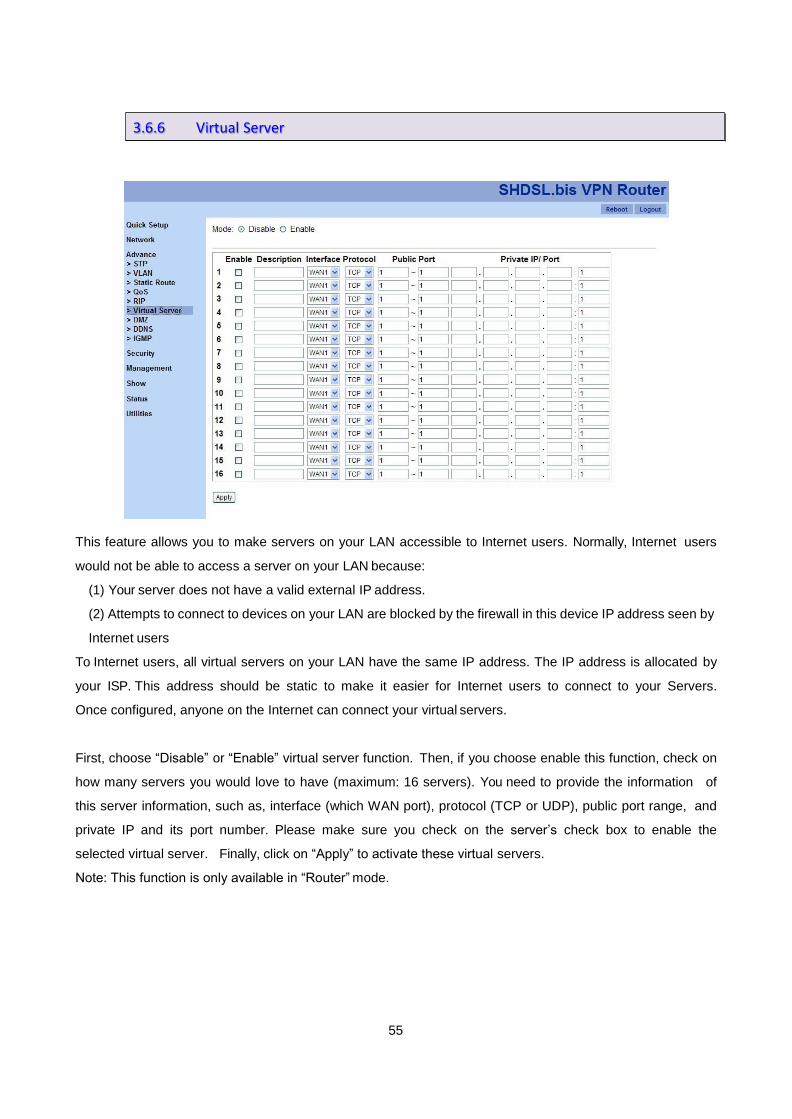
This feature allows you to make servers on your LAN accessible to Internet users. Normally, Internet users
would not be able to access a server on your LAN because:
(1) Your server does not have a valid external IP address.
(2) Attempts to connect to devices on your LAN are blocked by the firewall in this device IP address seen by
Internet users
To Internet users, all virtual servers on your LAN have the same IP address. The IP address is allocated by
your ISP. This address should be static to make it easier for Internet users to connect to your Servers.
Once configured, anyone on the Internet can connect your virtual servers.
First, choose “Disable” or “Enable” virtual server function. Then, if you choose enable this function, check on
how many servers you would love to have (maximum: 16 servers). You need to provide the information of
this server information, such as, interface (which WAN port), protocol (TCP or UDP), public port range, and
private IP and its port number. Please make sure you check on the server’s check box to enable the
selected virtual server. Finally, click on “Apply” to activate these virtual servers.
Note: This function is only available in “Router” mode.
3.6.6 Virtual Server

56
DMZ (demilitarized zone) is a physical or logical sub-network that contains and exposes an organization's
external services to a larger distrusted network, usually the Internet. The purpose of a DMZ is to add an
additional layer of security to an organization's LAN (Local Area Network).
In DMZ feature, three parameters needed to build up a DMZ function for a WAN port.
1. Mode:
Choose “Disable” to disable DMZ feature and “Enable” to start this function.
2. WAN I/F
Choose which WAN port should be applied.
3. Host IP
Assign a host IP for the WAN port.
Note: DMZ function is only available in “Router” mode.
3.6.7 DMZ

57
DDNS (Dynamic DNS Free) is a method, protocol or network service that provides the capability for a
networked device, such as, a router, to notify a DNS name server to change the active DNS configuration of
its configured hostnames, addresses or other information.
1. Mode: to disable or enable DDNS function.
2. Provider:
XL-GRT60x VPN Router provides three DNS name service providers. Please choose a provider
from the following list.
www.dyndns.com
www.no-ip.com
www.tzo.com
3. Host Name: the host name you registered in the selected provider.
4. User Name: the account name you have for the selected provider.
5. Password: the password for the selected provider.
3.6.8 DDNS

58
IGMP (Internet Group Management Protocol) proxy can be used to implement multicast routing. It works by
IGMP frame forwarding. VPN Router’s IGMP proxy supports IGMP version 2 (RFC2236). IGMP proxy
works in router mode (Layer 3); in the other hand, IGMP snooping works in bridge mode (Layer 2).
When IGMP function is “Enable”, the received IGMP packets will be forwarded to the intranet devices which
need to receive IGMP packets.
3.6.9 IGMP

59
“Security” section includes three features:
1. Firewall
2. VPN
3. Filter
The following sections will guide you some details of these features.
A firewall is a set of related programs that protects the resources of a private network from other networks. It
prevents hackers to access its own private data resource accidentally.
There are four firewall modes: “Disable”, “Low”, “Medium” and “High”. The table below shows what kind of
packets will be blocked in different modes.
Note: “Firewall” function is only available in “Router” mode.
3.7 Security
3.7.1 Firewall

60
A VPN (Virtual Private Network) provides a secured connection between 2 points in an insecure network.
The secured connection is called a VPN Tunnel. XL-GRT60x VPN Router supports three main types of
VPN: IPSEC, L2TP and PPTP.
Note: “VPN” function is only available in “Router” mode.
IPSEC is a near-ubiquitous VPN security standard, designed for use with TCP/IP networks. It works at the
packet level, and authenticates and encrypts all packets traveling over the VPN Tunnel.
IPSEC VPNs exchange information through logical connections called SAs(Security Associations). An SA is
simply a definition of the protocols, algorithms and keys used between the two VPN devices (endpoints).
3.7.2 VPN
3.7.2.1 IPSEC

61
Click on the number of each entry and the configuration page will be shown as below.
IPSec configuration parameters:
1. Mode: to disable or enable the selected IPSEC policy.
2. Name: IPSEC policy name.
3. WAN: to select a WAN port to apply this policy.
4. Perfect Forward Secrecy:
Perfect forward secrecy is the property that ensures a session key derived from a set of long-term public
and private keys will not be compromised if one of the private keys is compromised in the future.
Choose either “Disable” or “Enable” this property.
5. Local Subnet
6. Local Netmask
7. Remote Public IP
8. Remote Local LAN Subnet
9. Remote Local LAN Netmask
10. Pre-shared Key

62
Example: Configuring a IPSec LAN-to-LAN VPN Connection
Network Configuration and Security Plan
Branch Office Head Office
Local Network ID 192.168.0.0/24 192.168.1.0/24
Local Router IP 69.1.121.30 69.1.121.3
Remote Network ID 192.168.1.0/24 192.168.0.0/24
Remote Router IP 69.1.121.3 69.1.121.30
IKE Pre-shared Key 12345678 12345678
VPN Connection Type Tunnel mode Tunnel mode
Security Algorithm ESP:MD5 with AES ESP:MD5 with AES
Both office LAN networks must in different subnet with LAN to LAN application.
Functions of Pre-shared Key, VPN Connection, type and Security Algorithm must be identically set up on both
sides.
Example: Configuring a IPSec Host-to-LAN VPN Connection

63
L2TP (Layer 2 Tunneling Protocol) is a tunneling protocol used to support VPNs. It doesn’t provide any
encryption or confidentiality by itself; it relies on an encryption protocol that it passes within the tunnel to
provide privacy.
L2TP configuration parameters:
1. Mode: to disable or enable L2TP policy.
2. Authentication: choose authentication type, PAP, CHAP, MS-CHAP, and MS-CHAPv2.
3. Virtual IP
4. L2TP/IPSec Mode: check this checkbox if devices requires for L2TP/IPSec connection.
5. IPSec Interface
6. IPSec PSK: IPSec Pre-Shared Key.
7. User and Password sets
3.7.2.2 L2TP

64
Example: Configuring L2TP LAN-to-LAN VPN Connection
The branch office establishes a L2TP VPN tunnel with head office to connect two private networks over the
Internet. The routers are installed in the head office and branch office accordingly.
Both office LAN networks must in different subnet with LAN to LAN application.
Functions of Pre-shared Key, VPN Connection Type and Security Algorithm must be identically set up on both
sides.

65
PPTP (Point-to-Point Tunneling Protocol) is a private network of computers that uses the public Internet to
connect some nodes. Because the Internet is essentially an open network, the PPTP is used to ensure that
messages transmitted from one VPN node to another are secured. With PPTP, users can dial in to their
corporate network via the Internet. In “PPTP” function, there are three basic parameters to setup.
1. Mode: to enable or disable PPTP feature.
2. Authentication: four authentication modes can be chosen, PAP, CHAP, MS-CHAP, and MS-PAP.
3. Virtual IP
In addition, you are able to store four sets of user names and passwords in “PPTP” function.
There are two types of PPTP VPN supported; Remote Access and LAN-to-LAN.
Example: Configuring a Remote Access PPTP VPN Dial-out Connection
A company’s office establishes a PPTP VPN connection with a file server located at a separate location. The
router is installed in the office, connected to a couple of PCs and Servers.
3.7.2.3 PPTP
66
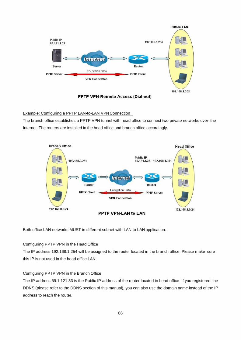
Example: Configuring a PPTP LAN-to-LAN VPN Connection
The branch office establishes a PPTP VPN tunnel with head office to connect two private networks over the
Internet. The routers are installed in the head office and branch office accordingly.
Both office LAN networks MUST in different subnet with LAN to LAN application.
Configuring PPTP VPN in the Head Office
The IP address 192.168.1.254 will be assigned to the router located in the branch office. Please make sure
this IP is not used in the head office LAN.
Configuring PPTP VPN in the Branch Office
The IP address 69.1.121.33 is the Public IP address of the router located in head office. If you registered the
DDNS (please refer to the DDNS section of this manual), you can also use the domain name instead of the IP
address to reach the router.

67
There are two features in “Filter” function: “IP Filter” and “MAC Filter”.
“IP Filter” allows users to filter packets by IP address. Two sections are in “IP Filter” feature. The first
section includes “Mode”, which allows user to enable or disable IP filter feature, and “Default Policy”, include
“Deny”, “Permit” and “Reject”.
3.7.3 Filter
3.7.3.1 IP filter

68
In the second section, you are able to configure each entry by clicking on the number on the table. Then, a
configuration page as the following screen shot will be shown.
Six elements are included in this configuration page:
1. Mode: to enable or disable this policy entry.
2. Action: “Deny”, “Permit” or “Reject” the packets.
3. Protocol: It is the packet protocol type used by the application, select among from TCP or UDP or both of
TCP/UDP.
4. Source IP Address / Destination IP Address: This is the Address-Filter used to allow or block traffic to/from
particular IP address. Selecting the Subnet Mask of the IP address range you wish to allow/block the
traffic to or form; set IP address and Subnet Mask to 0.0.0.0 to inactive the Address-Filter rule.
5. Source Port: This Port or Port Ranges defines the port allowed to be used by the Remote/WAN to
connect to the application. Default is set from range 0 ~ 65535. It is recommended that this option be
configured by an advanced user.
6. Destination Port: This is the Port or Port Ranges that defines the application.
Application
Protocol Port Number
Start End
HTTP TCP 80 80
DNS UDP 53 53
DNS TCP 53 53
FTP TCP 21 21
Telnet TCP 23 23
SMTP TCP 25 25
POP3 TCP 110 110
NEWS(NNTP) TCP 119 119
Real Audio/ Real Video UDP 7070 7070

69
PING ICMP N/A N/A
H.323 TCP 1720 1720
T.120 TCP 1503 1503
SSH TCP 22 22
NTP /SNTP UDP 123 123
HTTP/HTTP Proxy TCP 8080 8080
HTTPS TCP 443 443
ICQ TCP 5190 5190
MSN(1863) TCP 1863 1863
MSN(7001) UDP 7001 7001
MSB video TCP 9000 9000

70
“MAC Filter” function refers to a security access control methodology whereby the 48-bit address
(XX:XX:XX:XX:XX:XX) assigned to each network device is used to determine access to the network. MAC
addresses are uniquely assigned to each network device, so using MAC filtering on a network permits and
denies network access to specific devices through the use of black lists and white lists.
In “MAC Filter” page, you need to provide the following information in order to allow the VPN router to activate
MAC filtering function.
1. Mode: to enable or disable “MAC Filter” feature.
2. Default Policy: “Deny”, “Permit”, or “Reject” packets from selected MAC addresses.
3. Policy Entry: there are 16 entries available in this feature. Check the check box of “Mode” to enable this
policy, fill up MAC address in the text box of “MAC” and choose policy action from the drop-down menu of
“Action.
3.7.3.2 MAC filter

71
“Management” section provides eight features:
1. SNTP
2. SNMP
3. TR069
4. UPnP
5. Sys Log
6. Telnet
7. SSH
8. Web
Time synchronization is an essential element for any business, which relies on the IT system. The reason for
this is that these systems all have clock that is the source of timer for their filing or operations. Without time
synchronization, these system’s clocks vary and cause the failure of firewall packet filtering schedule
processes, compromised security, or virtual server working in wrong schedule.
SNTP is the acronym for Simple Network Time Protocol, which is an adaptation of the Network Time Protocol
(NTP) used to synchronize computer clocks in the Internet. SNTP can be used when the ultimate
performance of the full NTP implementation. “SNTP” function is only available in “Router” mode.
3.8 Management
3.8.1 SNTP
3.8.1.1 Sync with PC

72
“Sync with PC” allows the VPN router to synchronize with computer’s internal timer. Click on “Sync” button
in order to start synchronization.
“SNTP” features allow you to synchronize the time with the time server you provided. In order to make this
feature works, you need to provide the following parameters.
1. Mode: to enable or disable this feature.
2. Time Server: the address of a time server you wish to follow the time with.
3. Time Zone: choose the time zone of this VPN router with the drop-down menu.
3.8.1.2 SNTP

73
Simple Network Management Protocol (SNMP) provides for the exchange of messages between a network
management client and a network management agent for remote management of network nodes. These
messages contain requests to get and set variables that exist in network nodes in order to obtain statistics, set
configuration parameters, and monitor network events. SNMP communications can occur over the LAN or
WAN connection.
Three SNMP methods are available in “SNMP” function: 1. General, 2. SNMPv3 and 3. Trap.
You are able to enable SNMPv1 and SNMPv2 from “General” section. First, you need to click on “Enable”
radio button to enable this SNMP feature. Then, click on the number of the policy entry you want in the table.
A policy configuration page will be shown as the screen shot below.
3.8.2 SNMP
3.8.2.1 General

74
In this configuration page, you need to enable or disable this policy entry, provide a name in “Community” text
box, and assign access mode from the drop-down menu of “Access”. Click “Save” button to finish this
configuration section.
“SNMPv3” feature lets you to fill up the detail information, such as, password, for SNMPv3 function by click on
the number of each policy entry. Then, you will see the following screen shot.
(Note: Please make sure you choose “Enable” to allow the VPN router supports SNMPv3.)
3.8.2.2 SNMPv3

75
Once you fill up all the information needed, click on “Save” to finish this configuration.
With “Trap” feature, the VPN router is able to support SNMP Trap function. You are able to disable or enable
this feature by click on the radio buttons of “Mode”. Then, if you would like to modify each policy in the table,
please click on the number. Then, you are able to see the screen shot below.
3.8.2.3 Trap

76
TR-069 (Technical Report 069) is a DSL Forum technical specification entitled CPE WAN Management
Protocol (CWMP). It defines an application layer protocol for remote management of end-user devices.
As a bidirectional HTTP based protocol, it provides the communication between CPE (customer premises
equipment) and ACS (Auto Configuration Servers). Using TR-069 the terminals can get in contact with the
ACS (Auto Configuration Servers) and establish the configuration automatically.
1. Mode: to turn on or turn off TR069 feature.
2. ACS URL: to fill up URL for connecting to the ACS using the CPE WAN Management Protocol. This
parameter MUST be in the form of a valid HTTP or HTTPs URL.
3. ACS User Name: this username is used only for HTTP-based authentication of the CPE.
3.8.3 TR-069

77
4. ACS Password
5. Periodic Inform Enable
6. Periodic Inform Interval: the duration in seconds of the interval, for which the CPE attempts to connect
with the ACS and call the Inform method.
7. Periodic Inform Time
8. Connection Request IP: two options: automatic or manual (if you choose “Manual”, please fill up the IP
address.)
9. Connection Request Port
10. Connection Request Username: the username used to authenticate an ACS making a Connection
Request to the CPE.
11. Connection Request Password: the password used to authenticate an ACS making a Connection
Request to the CPE.
To “enable” UPnP (Universal Plug and Play) allows automatic discovery and configuration of equipment
attached to your LAN. UPnP is supported by Windows ME, XP or later.
“Enable”: this VPN Router will be visible via UPnP
“Disable”: this VPN Router will not be visible via UPnP
3.8.4 UPnP

78
Syslog is a standard method of centralizing various logs. You can use a syslog server to store your server’s
logs in a remote location for later perusal or long-term storage.
To send logs to the LOG server, please provide the following information.
1. Remote Server Mode: click on “Enable” button to send logs to a remote server.
2. Remote Server Address: this allows you to send logs to different files in the syslog server.
3. Remote Server Port: to specify a UDP port number to which the syslog server is listening. The default
value is 514. Also, please make sure this port is not blocked from your firewall.
You are able to change the default port of the VPN router’s Telnet function in this feature.
1. Mode: to enable or disable Telnet function of this VPN router.
3.8.5 Sys Log
3.8.6 Telnet

79
2. Port: the default port number is 23. Please fill in a number from 1 to 65535 if you want to change another
port number.
SSH (or Secure Shell) is a protocol that can be used to log into a remote machine (your Virtual Server) and
provide secure encrypted communications between your VPN Router and your local computer. All of the
commands you would use in a Telnet client, you can use in an SSH client. The only difference is that the
communication is made via encrypted channels to and from your VPN Router.
In “SSH” function, you are able to change the default port number.
1. Mode: to enable or disable SSH function.
2. Port: the default port number is 22. You are able to change the port number by providing a number from
1 to 65535.
3.
In “Web” function, you are able to change some setups as the following list.
1. Refresh Time: you are able to refresh your web page in a particular time intervals. The default interval is
3.8.7 SSH
3.8.8 Web

80
2 seconds.
2. Service Port: the default port number is 80. You are able to change this port number to a new one and
please make sure you login with this new port number next time.

81
Three functions are available in “Show” section.
1. Information
2. Sys Log
3. Script
“Information” feature shows the general system information, such as, hardware and software MCSV (the
Manufacture's Concurrent Software Version), software version, etc. (Note: please include a screen shot of
this page when you request any technical support!)
1. Hardware MCSV
2. Software MCSV
3. Software Version
4. DSL Chip Name
5. DSL Phy Firmware Version
6. DSL IDC Firmware Version
7. MAC
3.9 Show
3.9.1 Information

82
8. Serial No.
9. Present Time
10. System Uptime: the total time the VPN router is on.
“Sys Log” feature shows all of system logs.
“Script” presents the VPN router’s system setups in script manner. Clicking on “Export” button will generate
a file, includes all configurations of the VPN router.
3.9.2 Sys Log
3.9.3 Script

83
“Status” section provides five features:
1. SHDSL
2. WAN
3. Route Table
4. Interfaces
5. STP
For 2-wire models:
For 4-wire models:
3.10 Status
3.10.1 SHDSL

84
For 8-wire models:
If the VPN router have connected to remote side, it can also show the performance information of remote
side.
Click “Clear CRC” button will clear the CRC error count.
“WAN” feature presents all information of eight WAN interfaces.
3.10.2 WAN
85
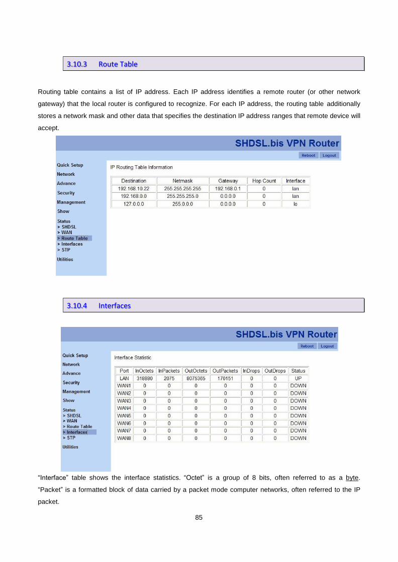
Routing table contains a list of IP address. Each IP address identifies a remote router (or other network
gateway) that the local router is configured to recognize. For each IP address, the routing table additionally
stores a network mask and other data that specifies the destination IP address ranges that remote device will
accept.
“Interface” table shows the interface statistics. “Octet” is a group of 8 bits, often referred to as a byte.
“Packet” is a formatted block of data carried by a packet mode computer networks, often referred to the IP
packet.
3.10.3 Route Table
3.10.4 Interfaces

86
InOctets The field shows the number of received bytes on this port
InPactets The field shows the number of received packets on this port
OutOctets The field shows the number of transmitted bytes on this port
OutPactets The field shows the number of transmitted packets on this port
InDrops The field shows the discarded number of received packets on this port
OutDrops The field shows the discarded number of transmitted packets on this port

87
There are five features in “Utilities” function:
1. Upgrade
2. Config Tool
3. Users
4. Ping
5. Trace Route
“Upgrade” features allows user to upgrade firmware. Click on “Browser” button and browse to the file you
wish to upgrade in your computer. Then, click on “Upgrade” button to commence the firmware upgrade.
3.11 Utilities
3.11.1 Upgrade

88
This configuration tool has three functions:
1. Default: to load the factory default settings to the VPN router.
2. Backup: to backup the current setups of the VPN router. The default file name is “config1.log”
3. Restore: to restore the VPN router’s configuration from a selected file.
You are able to choose which function you will do from the drop-down menu of “Mode” and click on “Apply”
button to start the process.
For a better security, change the Administrator name and password for the VPN router. The default
administrator name and password are “root”. Five sets of users and passwords can be stored in the VPN
router. Click on the number of each entry to start the configuration.
3.11.2 Config Tool
3.11.3 Users

89
1. Name: the user name
2. Level: three levels are available, administrator, normal and guest. Functions will be shown according to
users’ authorization level.
3. Password
4. Password Confirm
Ping test determines whether your VPN router can communicate with another computer or other web sites
over the network. Then, if network communication is established, ping tests also determine the connection
latency (technical term for delay) between the two device. You can use a ping test to troubleshoot
connectivity problems with your home network. Ping tests are also commonly used to measure the delay
("lag") with some Internet servers.
3.11.4 Ping

90
1. IP Address : Which IP address you want to ping
2. Size : Size of byte packets to the destination, default is 56
3. Count : Ping count number, default is 3
4. Update : Updated time, default is 2
Once you click on “Ping”, you will see the following screen shot.
The trace route command traces the network path of Internet routers that packets take as they are forwarded
from your VPN router to a destination address.
1. Host name or IP
3.11.5 Trace Route

91
2. Packet Datagram: the packet type, UDP or IGMP.
3. Update Interval: for the refresh interval.
Once you click on “Trace Route” button, you will see the following screen shot.

92
Abbreviation Full Name Meaning
ACS Auto Configuration Server The management server for TR-069 compliant
Customer Premises Equipment.
APN Access Point Name APN identifies an IP packet data network (PDN), that a
mobile data user wants to communicate with. In
addition to identifying a PDN, an APN may also be
used to define the type of service, (eg. connection to
wireless application protocol (WAP) server, multimedia
messaging service (MMS)), that is provided by the
PDN.
CBR Constant Bit Rate CBR is used by connections that require a static
amount of bandwidth that is available during the
connection life time. This bandwidth is characterized
by Peak Cell Rate (PCR). Based on the PCR of the
CBR traffic, specific cell slots are assigned for the VC in
the schedule table. The ATM always sends a single
cell during the CBR connection’s assigned cell slot.
CFI Canonical Format
Indicator
CFI is always set to zero for Ethernet switches. CFI is
used for compatibility reason between Ethernet type
network and Token Ring type network.
DDNS Dynamic DNS Dynamic DNS is a method, protocol, or network service
that provides the capability for a networked device,
such as, a router or computer system using the Internet
Protocol Suite, to notify a Domain Name System (DNS)
name server to change, in real time, the active DNS
configuration of its configured hostnames, addresses or
other information.
DHCP Dynamic Host
Configuration Protocol
DHCP is an auto-configuration protocol used on IP
networks. DHCP allows a computer to be configured
automatically, eliminating the need for intervention by a
network administrator. It also provides a central
database for keeping track of computers that have
been connected to the network. This prevents two
computers from accidentally being configured with the
Appendix A. Terminology
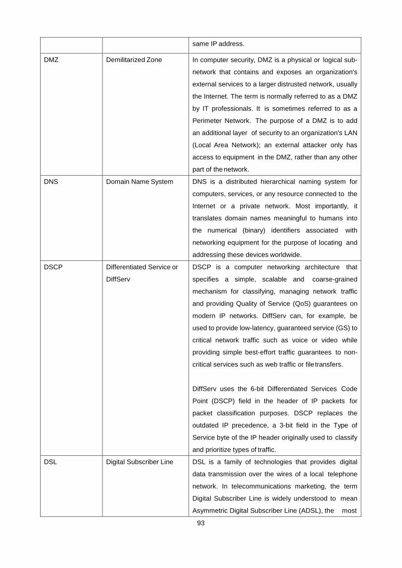
93
same IP address.
DMZ Demilitarized Zone In computer security, DMZ is a physical or logical sub-
network that contains and exposes an organization's
external services to a larger distrusted network, usually
the Internet. The term is normally referred to as a DMZ
by IT professionals. It is sometimes referred to as a
Perimeter Network. The purpose of a DMZ is to add
an additional layer of security to an organization's LAN
(Local Area Network); an external attacker only has
access to equipment in the DMZ, rather than any other
part of the network.
DNS Domain Name System DNS is a distributed hierarchical naming system for
computers, services, or any resource connected to the
Internet or a private network. Most importantly, it
translates domain names meaningful to humans into
the numerical (binary) identifiers associated with
networking equipment for the purpose of locating and
addressing these devices worldwide.
DSCP Differentiated Service or
DiffServ
DSCP is a computer networking architecture that
specifies a simple, scalable and coarse-grained
mechanism for classifying, managing network traffic
and providing Quality of Service (QoS) guarantees on
modern IP networks. DiffServ can, for example, be
used to provide low-latency, guaranteed service (GS) to
critical network traffic such as voice or video while
providing simple best-effort traffic guarantees to non-
critical services such as web traffic or file transfers.
DiffServ uses the 6-bit Differentiated Services Code
Point (DSCP) field in the header of IP packets for
packet classification purposes. DSCP replaces the
outdated IP precedence, a 3-bit field in the Type of
Service byte of the IP header originally used to classify
and prioritize types of traffic.
DSL Digital Subscriber Line DSL is a family of technologies that provides digital
data transmission over the wires of a local telephone
network. In telecommunications marketing, the term
Digital Subscriber Line is widely understood to mean
Asymmetric Digital Subscriber Line (ADSL), the most

94
commonly installed technical variety of DSL. DSL
service is delivered simultaneously with regular
telephone on the same telephone line. This is
possible because DSL uses a higher frequency.
EoA Ethernet-over-ATM EoA protocol is commonly used to carry data between
local area networks that use the Ethernet protocol and
wide-area networks that use the ATM protocol. Many
telecommunications industry networks use the ATM
protocol. ISPs that provide DSL services often use
the EoA protocol for data transfer with their customers'
DSL modems.
IGMP Internet Group
Management Protocol
IGMP is a communications protocol used to manage
the membership of Internet Protocol multicast groups.
IGMP is used by IP hosts and adjacent multicast
routers to establish multicast group memberships.
IPoA Dynamic IP over ATM IPoA interfaces carries IP packets over AAL5. AAL5
provides the IP hosts on the same network with the
data link layer for communications. In addition, to
allow these hosts to communicate on the same ATM
networks, IP packets must be tuned somewhat. AS
the bearer network of IP services, ATM provides high
speed point-to-point connections which considerably
improve the bandwidth performance of IP network.
On the other hand, ATM provides excellent network
performance and perfect QoS.
MSCV Manufacture's Concurrent
Software Version
MCSV is the original factory version and remains even
after upgrading the router in the field. This is for
internal identification purposes.
NAT Network Address
Translation
NAT is the process of modifying network address
information in datagram (IP) packet headers while in
transit across a traffic routing device for the purpose of
remapping one IP address space into another.
PCR Peak Cell Rate PCR in kbps: The maximum rate at which you expect to
transmit data, voice and video. Consider PCR and
MBS as a means of reducing latency, not increasing
bandwidth.
Port-Based VLAN Known as Static VLAN Static VLAN assignments are created by assigning
ports to a VLAN. As a device enters the network, the
device automatically assumes the VLAN of the port. If

95
the user changes ports and needs access to the same
VLAN, the network administrator must manually make
a port-to-VLAN assignment for the new connection.
PPPoA Point-to-Point Protocol
over ATM
PPPoA and PPPoE are authentication and connection
protocols used by many service providers for
broadband Internet access. These are specifications
for connecting multiple computer users on an Ethernet
local area network to a remote site through common
customer premises equipment, which is the telephone
company's term for a modem and similar devices.
PPPoE and PPPoA can be used to office or building.
Users share a common Digital Subscriber Line (DSL),
cable modem, or wireless connection to the Internet.
PPPoE and PPPoA combine the Point-to-Point
Protocol (PPP), commonly used in dialup connections,
with the Ethernet protocol or ATM protocol, which
supports multiple users in a local area network. The
PPP protocol information is encapsulated within an
Ethernet frame or ATM frame.
PPPoE Point-to-Point Protocol
over Ethernet
PVID Port VID PVID is an untagged member from 1 to 4094 of default
VLAN.
QoS Quality of Service In the field of computer networking and other packet-
switched telecommunication networks, the traffic
engineering term quality of service (QoS) refers to
resource reservation control mechanisms rather than
the achieved service quality. QoS is the ability to
provide different priority to different applications, users,
or data flows, or to guarantee a certain level of
performance to a data flow.
RIP Routing Information
Protocol
The Routing Information Protocol (RIP) is a dynamic
routing protocol used in local and wide area networks.
As such it is classified as an interior gateway protocol
(IGP). It uses the distance-vector routing algorithm.
It was first defined in RFC 1058 (1988). The protocol
has since been extended several times, resulting in RIP
Version 2 (RFC 2453). Both versions are still in use
today, however, they are considered to have been
made technically obsolete by more advanced
techniques such as Open Shortest Path First (OSPF)

96
and the OSI protocol IS-IS. RIP has also been adapted
for use in IPv6 networks, a standard known as RIPng
(RIP next generation), published in RFC 2080 (1997).
SCR Sustained Cell Rate The sustained rate at which you expect to transmit
data, voice and video. Consider SCR to be the true
bandwidth of a VC and not the lone-term average traffic
rate.
SHDSL Single-Pair High-speed
Digital Subscriber Line
Single-Pair High-speed Digital Subscriber Line
(SHDSL) is a form of DSL, a data communications
technology that enables faster data transmission over
copper telephone lines than a conventional voice band
modem can provide.
SNMP Simple Network
Management Protocol
SNMP is a UDP-based network protocol. It is used
mostly in network management systems to monitor
network-attached devices for conditions that warrant
administrative attention. SNMP is a component of the
Internet Protocol Suite as defined by the Internet
Engineering Task Force (IETF). It consists of a set of
standards for network management, including an
application layer protocol, a database schema, and a
set of data objects.[1]
SNTP Simple Network Time
Protocol
A less complex implementation of NTP, using the same
protocol but without requiring the storage of state over
extended periods of time is known as the Simple
Network Time Protocol (SNTP). It is used in some
embedded devices and in applications where high
accuracy timing is not required.
SSH Secure Shell SSH is a network protocol that allows data to be
exchanged using a secure channel between two
networked devices. The two major versions of the
protocol are referred to as SSH1 or SSH-1 and SSH2
or SSH-2. Used primarily on Linux and Unix based
systems to access shell accounts, SSH was designed
as a replacement for Telnet and other insecure remote
shells, which send information, notably passwords, in
plaintext, rendering them susceptible to packet
analysis.[2] The encryption used by SSH is intended to
provide confidentiality and integrity of data over an
unsecured network, such as the Internet.

97
STP Spanning-Tree Protocol STP, defined in the IEEE 802.1D, is a link management
protocol that provides path redundancy while
preventing undesirable loops in the network. For an
Ethernet network to function properly, only one active
path can exist between two stations.
STU-C Central Office or CO.
STU-R Customer Premises Equipment or CPE.
TCI Tag Control Information
field
TCI includes user priority, Canonical format indicator
(CFI) and VLAN ID.
TCP Transmission Control
Protocol
TCP is a connection-oriented protocol that is
responsible for reliable communication between two
end processes. The unit of data transferred is called a
stream, which is simply a sequence of bytes.
TC-PAM Trellis Coded Pulse
Amplitude Modulation
TC-PAM is the modulation format that is used in both
HDSL2 and SHDSL, and provides vigorous
presentation over an assortment of loop circumstances.
SHDSL uses TC-PAM to give a rate/reach adaptive
potential offering improved performance and enhanced
spectral compatibility with ADSL when compared to
today's traditional 2B1Q SDSL offerings.
ToS Type of Service The Type of Service (TOS) field in the IPv4 header has
had various purposes over the years, and has been
defined in different ways by five RFCs[note 1] The
modern redefinition of the TOS field is a six-bit
Differentiated Services Code Point (DSCP) field and a
two-bit Explicit Congestion Notification field.
TPID Tag Protocol Identifier TPID defined value of 8100 in hex. When a frame has
the EtherType equal to 8100H, this frame carries the
tag IEEE 802.1Q / 802.1P.
TR069 Technical Report 069 TR-069 is a DSL Forum (which was later renamed as
Broadband Forum) technical specification entitled CPE
WAN Management Protocol (CWMP). It defines an
application layer protocol for remote management of
end-user devices.
UBR Unspecified Bit Rate UBR (Unspecified Bit Rate) is the simplest service
provided by ATM networks. There is no guarantee of
anything. It is a primary service used for transferring
Internet traffic over the ATM network.

98
UDP User Datagram Protocol UDP (User Datagram Protocol) offers only a minimal
transport service (non-guaranteed datagram delivery)
and gives applications direct access to the datagram
service of the IP layer. UDP is used by applications that
do not require the level of service of TCP or that wish to
use communications services (e.g., multicast or
broadcast delivery) not available from TCP.
UPnP Universal Plug and Play Universal Plug and Play (UPnP) is a set of networking
protocols for primarily residential networks without
expert administrators that permits networked devices,
such as personal computers, printers, Internet
gateways, Wi-Fi access points, mobile device, to
seamlessly discover each other’s presence on the
network and establish functional network services for
data sharing, communications, and entertainment.
VBR-nrt Variable Bit Rate
non-real-time
VBR-nrt is intended for non-real-time applications, such
as FTP, e-mail and browsing.
VBR-rt Variable Bit Rate real-time VBR-rt is intended for real-time applications, such as
compressed voice over IP and video conferencing that
require tightly constrained delays and delay variation.
VBR-rt is characterized by a peak cell rate (PCR),
sustained cell rate (SCR), and maximum burst rate
(MBR).
VCI Virtual Channel Identifier for set up ATM Permanent Virtual Channels(PVC).
VID Virtual LAN ID VID (VLAN ID) is the identification of the VLAN, which
is basically used by the standard 802.1Q. It has 12 bits
and allow the identification of 4096 (212) VLANs. Of the
4096 possible VIDs, a VID of 0 is used to identify
priority frames and value 4095 (FFF) is reserved, so
the maximum possible VLAN configurations are 4,094.
The VPN Router initially default configures one VLAN,
VID=1.
VLAN Virtual LAN A VLAN is a group of hosts with a common set of
requirements that communicate as if they were
attached to the same broadcast domain, regardless of
their physical location. A VLAN has the same attributes
as a physical LAN, but it allows for end stations to be
grouped together even if they are not located on the
same network switch. Network reconfiguration can be

99
done through software instead of physically relocating
devices.
VPI Virtual Path Identifier For set up ATM Permanent Virtual Channels (PVC).
VPN Virtual Private Network A virtual private network (VPN) is a network that uses a
public telecommunication infrastructure and their
technology such as the Internet, to provide remote
offices or individual users with secure access to their
organization's network. It aims to avoid an expensive
system of owned or leased lines that can be used by
only one organization. The goal of a VPN is to provide
the organization with the same secure capabilities but
at a much lower cost.
WAN Wide Area Network WAN is a computer network that covers a broad area.
This is in contrast with personal networks (PANs), local
area networks (LANs), campus area networks (CANs)
or metropolitan area networks (MANs), which are
usually limited to a room, building, campus or specific
metropolitan area respectively.

100
Choose MGMT, LAN1 and WAN1 for entry 1 as one group for all configurations.
Configuration 1:
PVID Link Type
LAN1 20 Un-tag
WAN1 20 Tag
VID 1
Case 1
Ingress Port = LAN1 (un-tag)
Egress Port = WAN1 (tag)
Incoming Packet without VID
Appendix B. FAQ
B-1. 802.1Q Tag-Based VLAN Test Cases
PDU
VID = 20
PDU
LAN1 xl-grt60x Router WAN1

101
Case 2
Ingress Port = LAN1 (un-tag)
Egress Port = WAN1 (tag)
Incoming Packet with VID = 20
The packet will be dropped since the VID (20) is not matched with the VID (1) of the Egress port.
Case 3
Ingress Port = LAN1 (un-tag)
Egress Port = WAN1 (tag)
Incoming Packet with VID = 30
The packet will be dropped since the VID (30) is not matched with the VID (1) of the Egress port.
Case 4
Ingress Port = WAN1 (tag)
Egress Port = LAN1 (un-tag)
Incoming Packet with no VID
The packet will be dropped since the packet’s VID is not matched with WAN1’s VID (1).
VID = 20
PDU
LAN1 XL-GRT60x Router WAN1

102
Case 5
Ingress Port = WAN1 (tag)
Egress Port = LAN1 (un-tag)
Incoming packet with VID = 1
The VID will be removed and the packet will be forwarded.
LAN1

103
Configuration 2
PVID Link Type
LAN1 20 Un-tag
WAN1 30 Tag
VID 10
Case 1
Ingress Port = LAN1 (Un-tag)
Egress Port = WAN1 (Tag)
Incoming Packet with no VID
The packet is dropped because the VID is not matched with WAN1 VID (10).

104
Case 2
Ingress Port = LAN1 (Un-tag)
Egress Port = WAN1 (Tag)
Incoming Packet with VID = 10
Case 3
Ingress Port = LAN1 (Un-tag)
Egress Port = WAN1 (Tag)
Incoming Packet with VID = 30
The packet is dropped because the packet’s VID (30) is not matched with WAN VID (10).
Case 4
Ingress Port = WAN1 (Tag)
Egress Port = LAN1 (Un-tag)
Incoming Packet with no VID
The packet is dropped because the packet’s VID is not matched with VID.
VID = 30
PDU
LAN1 XL-GRT60x Router WAN1

105
Case 5
Ingress Port = WAN1 (Tag)
Egress Port = LAN1 (Un-tag)
Incoming Packet with VID = 30
The packet is dropped because the packet’s VID (30) is not matched with VID (10).
Case 6
Ingress Port = WAN1 (Tag)
Egress Port = LAN1 (Un-tag)
Incoming Packet with VID = 10
The packet’s VID will be removed and the packet will be forward.
VID = 30
PDU
WAN1 XL-GRT60x Router LAN1

106
Port-Based VLANs are VLANs where the packet forwarding decision is based on the destination MAC
address and its associated port.
When using the port-based VLAN, the port is assigned to a specific VLAN independent of the user or system
attached to the port. This means all users attached to the port should be members in the same VLAN. The
network administrator typically performs the VLAN assignment. The port configuration is static and cannot
be automatically changed to another VLAN without manual reconfiguration.
As with other VLAN approaches, the packets forwarded using this method do not leak into other VLAN
domains on the network. After a port has been assigned to a VLAN, the port cannot send to or receive from
devices in another VLAN.
For example,
The default setting is all ports connected which means all ports can communicate with each other. That is,
there are no virtual LANs. The option is the most flexible but the least secure.
B-1. What is IP DSCP?
Differentiated Services (DiffServ) is a class of service (CoS) model that enhances best-effort Internet services
by differentiating traffic by users, service requirements and other criteria. Packet are specifically marked,
allowing network nodes to provide different levels of service, as appropriate for video playback, voice calls or
other delay-sensitive applications, via priority queuing or bandwidth allocation.
DiffServ defines a new DS(Differentiated Services) field to replace the Type of Service(ToS) field in the IP
header. The DS field contains a 2-bits unused field and 6-bits DSCP field which can define up to 64 service
levels.
The following figure illustrates the DS field:
B-2. Port-Based VLAN

107
The DSCP value used to identify 64 levels (26=64) of service determines the forwarding behavior that each
packet gets across the DiffServ network. Based on the marking rule different kinds of traffic can be marked
for different priorities of forwarding. Resources can then be allocated according to the DSCP values and the
configured policies.
The following is an illustration about how the bits are used in DSCP field.
Bit 0 Bit 1 Bit 2 Precedence Usage
1
1
1
7
Stays the same(link layer and routing protocol keep
alive)
1 1 0 6 Stays the same(used for IP routing Protocols)
1 0 1 5 Express Forwarding (EF)
1 0 0 4 Class 4
0 1 1 3 Class 3
0 1 0 2 Class 2
0 0 1 1 Class 1
0 0 0 0 Best effort
Bit 3 Bit 4 Bit 5 Usage Meaning
0 -- -- Delay Normal
1 -- -- Delay Low
-- 0 -- Throughput Normal
-- 1 -- Throughput High

108
-- -- 0 Reliability Normal
-- -- 1 Reliability High
The standardized DiffServ field of the packet is marked with a value so that the packet receives a particular
forwarding treatment at each network node.
RFC 2597 defines the assured forwarding (AF) classes. There are four AF classes, AF1x through AF4x.
Within each class, there are three drop probabilities. Depending on a given network's policy, packets can be
selected for a PHB based on required throughput, delay, jitter, loss, or according to priority of access to
network services.
Classes 1 through 4 are referred to as AF classes.
The following table illustrates the DSCP coding for specifying the AF class with the probability. Bits 0, 1, and
2 define the class; bits 3 and 4 specify the drop probability; bit 5 is always 0.
Class 1 Class 2 Class 3 Class 4
Low Drop
001010
AF11
DSCP 10
010010
AF21
DSCP 18
011010
AF31
DSCP 26
100010
AF41
DSCP 34
Medium Drop
001100
AF12
DSCP 12
010100
AF22
DSCP 20
011100
AF32
DSCP 28
100100
AF42
DSCP 36
High Drop
001110
AF13
DSCP 14
010110
AF23
DSCP 22
011110
AF33
DSCP 30
100110
AF43
DSCP 38
The recommended DSCP values which are based on RFC 4594 are in the following table:
Service Class Name DSCP Name DSCP Value Application Examples
Network Control and
OAM
CS6 110000 (48) Network routing and OAM (e.g. SNMP,
Ethernet CFM, proprietary NMS traffic)
Signaling CS5 101000 (40) Signaling (e.g. H.323, SIP)
Telephony EF 101110 (46) IP Telephony bearer
Multimedia
Conferencing
AF41, AF42,
AF43
100010 (34), 100100
(36),
100110(38)
Videoconferencing
Real-Time CS4 100000 (32) Interactive control (e.g. CAM), real-time

109
Interactive e-learning, games, e-arts
Multimedia
Streaming
AF31,AF32,
AF33
011010 (26), 011100
(28),
011110 (30)
Streaming video and audio on demand
Broadcast Video CS3 011000 (24) Broadcast TV & live events
Low-Latency Data AF21,AF22,
AF23
010010 (18), 010100
(20),
010110 (22)
Transactional applications, database
access, interactive data applications
High-
Throughput
Data
AF11,AF12,
AF13
001010 (10), 001100
(12),
001110 (14)
Bandwidth channels
Standard (Best
Effort)
DF (CS0) 000000 (0) Undifferentiated applications
Low-Priority Data
(LBE)
CS1 001000 (8) Mirror service, remote backups, etc