xilinx logicore ip xps ethernet lite media access ... al so includes optional 2k byte dual port...
TRANSCRIPT
DS580 September 21, 2010 www.xilinx.com 1Product Specification
© 2006-2010 Xilinx, Inc. XILINX, the Xilinx logo, Artix, ISE, Kintex, Spartan, Virtex, and other designated brands included herein are trademarks of Xilinx in the United States and other countries
IntroductionThe Ethernet Lite MAC (Media Access Controller) isdesigned to incorporate the applicable featuresdescribed in the IEEE Std. 802.3 Media IndependentInterface (MII) specification, which should be used asthe definitive specification.
The Ethernet Lite MAC supports the IEEE Std. 802.3Media Independent Interface (MII) to industry stan-dard Physical Layer (PHY) devices and communicatesto a processor via a Processor Local Bus (PLB) interface.The design provides a 10 megabits per second (Mbps)and 100 Mbps (also known as Fast Ethernet) Interface.The goal is to provide the minimal functions necessaryto provide an Ethernet interface with the least resourcesused.
Features• Connects as 32-bit slave on PLB V4.6 buses of 32,
64 or 128 bits
• Supports single beat and burst transactions
• Memory mapped direct I/O interface to the transmit and receive data dual port memory
• Media Independent Interface (MII) for connection to external 10/100 Mbps PHY transceivers
• Independent internal 2K byte Tx and Rx dual port memory for holding data for one packet
• Optional dual buffer memories, 4K byte ping-pong, for Tx and Rx
• Receive and Transmit Interrupts
• Optional MDIO interface for PHY access
• Internal loop back support
0
LogiCORE IP XPS Ethernet LiteMedia Access Controller
DS580 September 21, 2010 0 0 Product Specification
LogiCORE IP Facts
Core Specifics
Supported Device Family
Virtex®-6, Spartan®-6, Virtex-5/5FX, Virtex-4/4QV/4Q, Automotive Spartan-3/3A/3A DSP/3E, Spartan-3E, Spartan-3, Spartan-3A, Spartan-3A DSP
Version of core 4.00a
Resources Used See Table 16,Table 17, Table 18, Table 19, and Table 20.
Special Features N/A
Provided with Core
Documentation Product Specification
Design File Formats VHDL
Constraints File N/A
Verification N/A
Instantiation Template N/A
Reference Designs /Application Notes N/A
Additional Items N/A
Design Tool Requirements
Xilinx Implementation Tools
ISE® 12.1
Verification Mentor Graphics® ModelSim: v6.5cand above
Simulation Mentor Graphics ModelSim: v6.5cand above
Synthesis XST
Support
Provided by Xilinx, Inc.
LogiCORE IP XPS Ethernet Lite Media Access Controller
2 www.xilinx.com DS580 September 21, 2010Product Specification
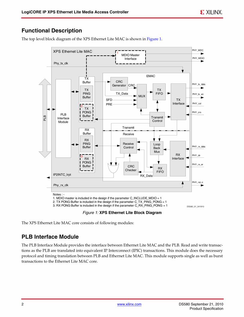
Functional DescriptionThe top level block diagram of the XPS Ethernet Lite MAC is shown in Figure 1.
The XPS Ethernet Lite MAC core consists of following modules:
PLB Interface ModuleThe PLB Interface Module provides the interface between Ethernet Lite MAC and the PLB. Read and write transac-tions as the PLB are translated into equivalent IP Interconnect (IPIC) transactions. This module does the necessaryprotocol and timing translation between PLB and Ethernet Lite MAC. This module supports single as well as bursttransactions to the Ethernet Lite MAC core.
X-Ref Target - Figure 1
Figure 1: XPS Ethernet Lite Block Diagram
PLB Interface Module
MUX
TX FIFO
Transmit Control
CRC
SFD
PRE
TX_Data
RX FIFO
Receive Control
CRC Checker
CRC Generator
MDIO Master Interface
PHY_MDC
PHY_MDIO
RX_DataIP2INTC_Irpt
PLB
Phy_rx_clk
Phy_tx_clk
PHY_rst_n
EMAC
TX Interface
RX Interface
Loop BackMux
XPS Ethernet Lite MAC
RX PING Buffer
RX PONG Buffer
RX Buffer
PHY_tx_data
PHY_tx_en
PHY_crs
PHY_col
PHY_rx_data
PHY_dv
PHY_rx_er
TX PING Buffer
TX PONG Buffer
TX Buffer
1
2
3
Notes : -1. MDIO master is included in the design if the parameter C_INCLUDE_MDIO = 12. TX PONG Buffer is included in the design if the parameter C_TX_PING_PONG = 13. RX PONG Buffer is included in the design if the parameter C_RX_PING_PONG = 1
Transmit
Receive
DS580_01_041910
DS580 September 21, 2010 www.xilinx.com 3Product Specification
LogiCORE IP XPS Ethernet Lite Media Access Controller
TX Buffer
The TX Buffer module consists of 2K byte dual port memory to hold transmit data for one complete frame and thetransmit interface control registers. It also includes optional 2K byte dual port memory for pong buffer based on theparameter C_TX_PING_PONG.
RX Buffer
The RX Buffer module consists of 2K byte dual port memory to hold receive data for one complete frame and thereceive interface control register. It also includes optional 2K byte dual port memory for pong buffer based on theparameter C_RX_PING_PONG.
Transmit
This module consists transmit logic, CRC generator module, transmit data mux, TX FIFO and transmit interfacemodule. CRC generator module calculates the CRC for the frame need to be transmitted. The transmit control muxarrange this frame and sends preamble, SFD, frame data, padding and CRC to the transmit FIFO in the requiredorder. Once the frame is transmitted to PHY, this module generates transmit interrupt and updates the transmitcontrol register.
Receive
This module consists of RX interface, loop back control mux, RX FIFO, CRC checker and receive control module.Receive data signals from the PHY are passed through loop back control mux and stored in RX FIFO. If loop backis enabled, data on TX lines is passed to RX FIFO. The CRC checker module calculates the CRC of the received frameand if the correct CRC is found, Receive control logic generates the frame receive interrupt.
MDIO Master Interface
MDIO Master Interface module is included in the design if the parameter C_INCLUDE_MDIO is set to ‘1’. Thismodule provide access to PHY register for PHY management. The MDIO interface is described in "ManagementData Input/Output (MDIO) Master Interface Module".
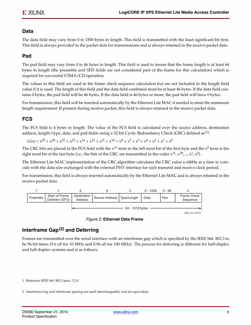
Ethernet ProtocolEthernet data is encapsulated in frames as shown in Figure 2. The fields in the frame are transmitted from left toright. The bits within the frame are transmitted from left to right (from least significant bit to most significant bitunless specified otherwise).
Preamble
The preamble field is used for synchronization and must contain seven bytes with the pattern “10101010”. The pat-tern is transmitted from left to right. If a collision is detected during the transmission of the preamble or start offrame delimiter fields, the transmission of both fields will be completed.
For transmission, this field is always automatically inserted by the Ethernet Lite MAC and should never appear inthe packet data provided to the Ethernet Lite MAC. For reception, this field is always stripped from the packet data.The Ethernet Lite MAC design does not support the ethernet 8-byte preamble frame type.
LogiCORE IP XPS Ethernet Lite Media Access Controller
4 www.xilinx.com DS580 September 21, 2010Product Specification
Start Frame Delimiter
The start frame delimiter field marks the start of the frame and must contain the pattern 10101011. The pattern istransmitted from left to right. If a collision is detected during the transmission of the preamble or start of framedelimiter fields, the transmission of both fields will be completed.
The receive data valid signal from the PHY (PHY_dv) may go active during the preamble but will be active prior tothe start frame delimiter field. For transmission, this field is always automatically inserted by the Ethernet LiteMAC and should never appear in the packet data provided to the Ethernet Lite MAC. For reception, this field isalways stripped from the packet data.
Destination Address
The destination address field is 6 bytes in length(1). The least significant bit of the destination address is used todetermine if the address is an individual/unicast (0) or group/multicast (1) address. Multicast addresses are usedto group logically related stations.
The broadcast address (destination address field is all 1’s) is a multicast address that addresses all stations on theLAN. The Ethernet Lite MAC supports transmission and reception of unicast and broadcast packets. The EthernetLite MAC core does not support multicast packets.
This field is transmitted with the least significant bit first. This field is always provided in the packet data for trans-missions and is always retained in the receive packet data.
Source Address
The source address field is 6 bytes in length(2). This field is transmitted with the least significant bit first. This fieldis always provided in the packet data for transmissions and is always retained in the receive packet data.
Type/Length
The type/length field is 2 bytes in length. When used as a length field, the value in this field represents the numberof bytes in the following data field. This value does not include any bytes that may have been inserted in the pad-ding field following the data field.
The value of this field determines if it should be interpreted as a length as defined by the IEEE 802.3 standard or atype field as defined by the ethernet protocol.
The maximum length of a data field is 1,500 bytes. Therefore, a value in this field that exceeds 1,500 (0x05DC) wouldindicates that a frame type rather than a length value is provided in this field. The IEEE 802.3 standard uses thevalue 1536 (0x0600) or greater to signal a type field.
The Ethernet Lite MAC does not perform any processing of the type/length field.
This field is transmitted with the least significant bit first but with the high order byte first. This field is always pro-vided in the packet data for transmissions and is always retained in the receive packet data.
1. The Ethernet Lite MAC design does not support 16-bit destination addresses as defined in the IEEE 802 standard.
2. The Ethernet Lite MAC does not support 16-bit source addresses as defined in the IEEE 802 standard.
DS580 September 21, 2010 www.xilinx.com 5Product Specification
LogiCORE IP XPS Ethernet Lite Media Access Controller
Data
The data field may vary from 0 to 1500 bytes in length. This field is transmitted with the least significant bit first.This field is always provided in the packet data for transmissions and is always retained in the receive packet data.
Pad
The pad field may vary from 0 to 46 bytes in length. This field is used to insure that the frame length is at least 64bytes in length (the preamble and SFD fields are not considered part of the frame for this calculation) which isrequired for successful CSMA/CD operation.
The values in this field are used in the frame check sequence calculation but are not included in the length fieldvalue if it is used. The length of this field and the data field combined must be at least 46 bytes. If the data field con-tains 0 bytes, the pad field will be 46 bytes. If the data field is 46 bytes or more, the pad field will have 0 bytes.
For transmission, this field will be inserted automatically by the Ethernet Lite MAC if needed to meet the minimumlength requirement. If present during receive packet, this field is always retained in the receive packet data.
FCS
The FCS field is 4 bytes in length. The value of the FCS field is calculated over the source address, destinationaddress, length/type, data, and pad fields using a 32-bit Cyclic Redundancy Check (CRC) defined as(1):
G(x) = x32 + x26 + x23 + x22 + x16 + x12 + x11 + x10 + x8 + x7 + x5 + x4 + x2 + x1 + x0
The CRC bits are placed in the FCS field with the x31 term in the left most bit of the first byte and the x0 term is theright most bit of the last byte (i.e., the bits of the CRC are transmitted in the order x31, x30,..., x1, x0).
The Ethernet Lite MAC implementation of the CRC algorithm calculates the CRC value a nibble at a time to coin-cide with the data size exchanged with the external PHY interface for each transmit and receive clock period.
For transmission, this field is always inserted automatically by the Ethernet Lite MAC and is always retained in thereceive packet data.
Interframe Gap(2) and Deferring
Frames are transmitted over the serial interface with an interframe gap which is specified by the IEEE Std. 802.3 tobe 96 bit times (9.6 uS for 10 MHz and 0.96 uS for 100 MHz). The process for deferring is different for half-duplexand full-duplex systems and is as follows:
1. Reference IEEE Std. 802.3 para. 3.2.8
X-Ref Target - Figure 2
Figure 2: Ethernet Data Frame
2. Interframe Gap and interframe spacing are used interchangeably and are equivalent.
Preamble Start of FrameDelimiter (SFD)
Destination Address
Source Address
64 - 1518 bytes
Type/Length Data Frame Check
Sequence Pad
7 6 4 2 0 - 1500 0 - 46 6 1
DS80_02_041910
LogiCORE IP XPS Ethernet Lite Media Access Controller
6 www.xilinx.com DS580 September 21, 2010Product Specification
Half-Duplex1. Even when it has nothing to transmit, the Ethernet Lite MAC monitors the bus for traffic by watching the carrier
sense signal (PHY_crs) from the external PHY. Whenever the bus is busy (PHY_crs = ’1’), the Ethernet LiteMAC defers to the passing frame by delaying any pending transmission of its own.
2. After the last bit of the passing frame (when carrier sense signal changes from true to false), the Ethernet LiteMAC starts the timing of the interframe gap.
3. The Ethernet Lite MAC will reset the interframe gap timer if carrier sense becomes true.
Full-Duplex1. The Ethernet Lite MAC does not use the carrier sense signal from the external PHY when in full duplex mode
because the bus is not shared and only needs to monitor its own transmissions. After the last bit of an EthernetLite MAC transmission, the Ethernet Lite MAC starts the timing of the interframe gap.
Carrier sense multiple access with collision detection (CSMA/CD) access method
A full duplex ethernet bus is by definition, a point to point dedicated connection between two ethernet devicescapable of simultaneous transmit and receive with no possibility of collisions.
For a half duplex ethernet bus, the CSMA/CD media access method defines how two or more stations share a com-mon bus.
To transmit, a station waits (defers) for a quiet period on the bus (no other station is transmitting (PHY_crs = ’0’))and then starts transmission of its message after the interframe gap period.
If, after initiating a transmission, the message collides with the message of another station (PHY_col - ’1’), then eachtransmitting station intentionally continues to transmit (jam) for an additional predefined period (32 bits for 10/100Mbps) to ensure propagation of the collision throughout the system.
The station remains silent for a random amount of time (backoff) before attempting to transmit again.
A station can experience a collision during the beginning of its transmission (the collision window) before its trans-mission has had time to propagate to all stations on the bus. Once the collision window has passed, a transmittingstation has acquired the bus.
Subsequent collisions (late collisions) are avoided because all other (properly functioning) stations are assumed tohave detected the transmission and are deferring to it.
The time to acquire the bus is based on the round-trip propagation time of the bus (64 byte times for 10/100 Mbps).
DS580 September 21, 2010 www.xilinx.com 7Product Specification
LogiCORE IP XPS Ethernet Lite Media Access Controller
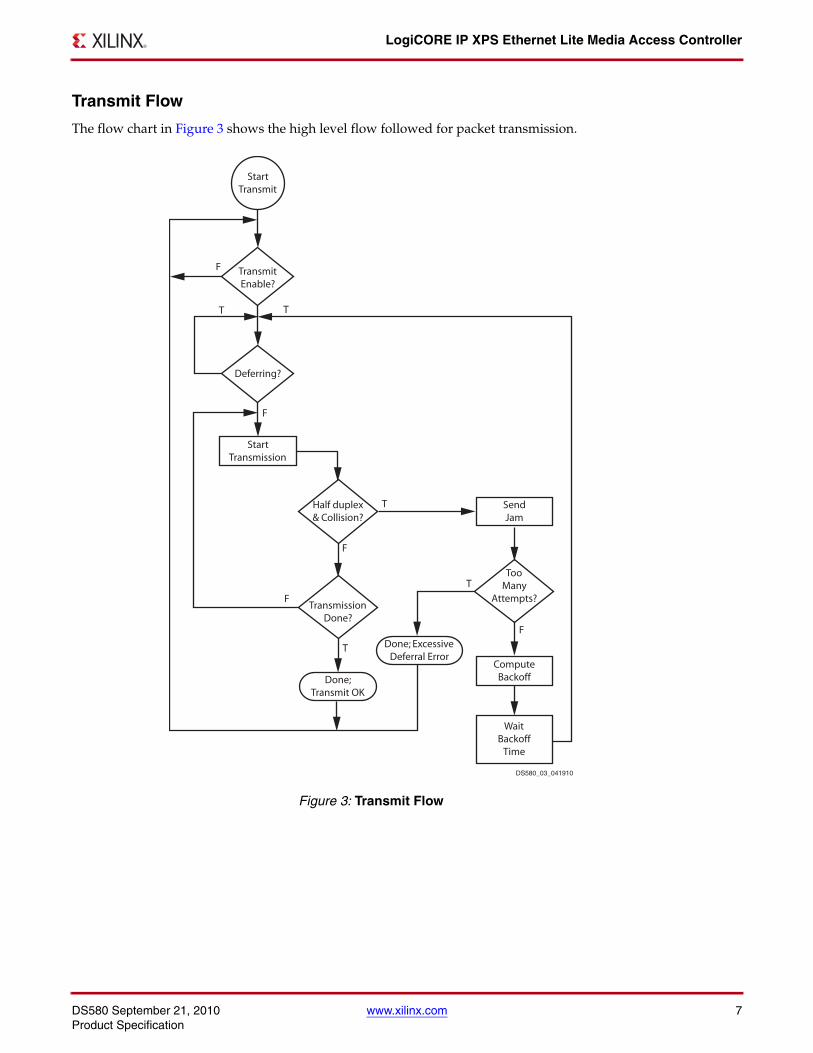
Transmit Flow
The flow chart in Figure 3 shows the high level flow followed for packet transmission.X-Ref Target - Figure 3
Figure 3: Transmit Flow
Start Transmission
Wait Backoff
Time
Send Jam
Compute Backoff
Start Transmit
Transmit Enable?
Half duplex & Collision?
Transmission Done?
Too Many
Attempts?
Deferring?
Done; Transmit OK
Done; Excessive Deferral Error
F
F
F
F
F
T T
T
T
T
DS580_03_041910
LogiCORE IP XPS Ethernet Lite Media Access Controller
8 www.xilinx.com DS580 September 21, 2010Product Specification
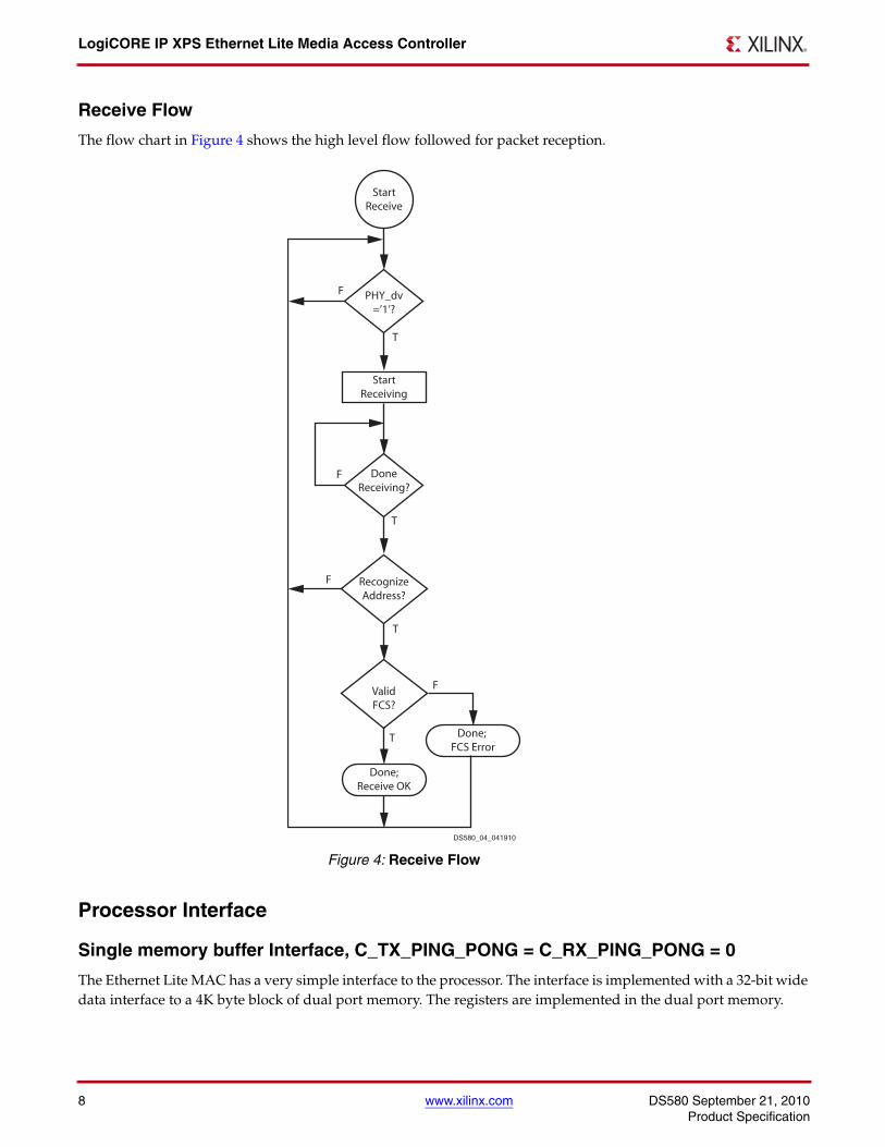
Receive Flow
The flow chart in Figure 4 shows the high level flow followed for packet reception.
Processor Interface
Single memory buffer Interface, C_TX_PING_PONG = C_RX_PING_PONG = 0
The Ethernet Lite MAC has a very simple interface to the processor. The interface is implemented with a 32-bit widedata interface to a 4K byte block of dual port memory. The registers are implemented in the dual port memory.
X-Ref Target - Figure 4
Figure 4: Receive Flow
Start Receiving
Start Receive
PHY_dv =’1’?
Recognize Address?
Valid FCS?
Done Receiving?
Done; Receive OK
Done; FCS Error
F
F
F
F
T
T
T
T
DS580_04_041910
DS580 September 21, 2010 www.xilinx.com 9Product Specification
LogiCORE IP XPS Ethernet Lite Media Access Controller
The dual port memory is allocated so that 2K bytes are dedicated to the transmit function and 2K bytes are dedi-cated to the receive function. This memory is capable of holding one maximum length ethernet packet in the receiveand transmit memory areas simultaneously.
Transmit Interface
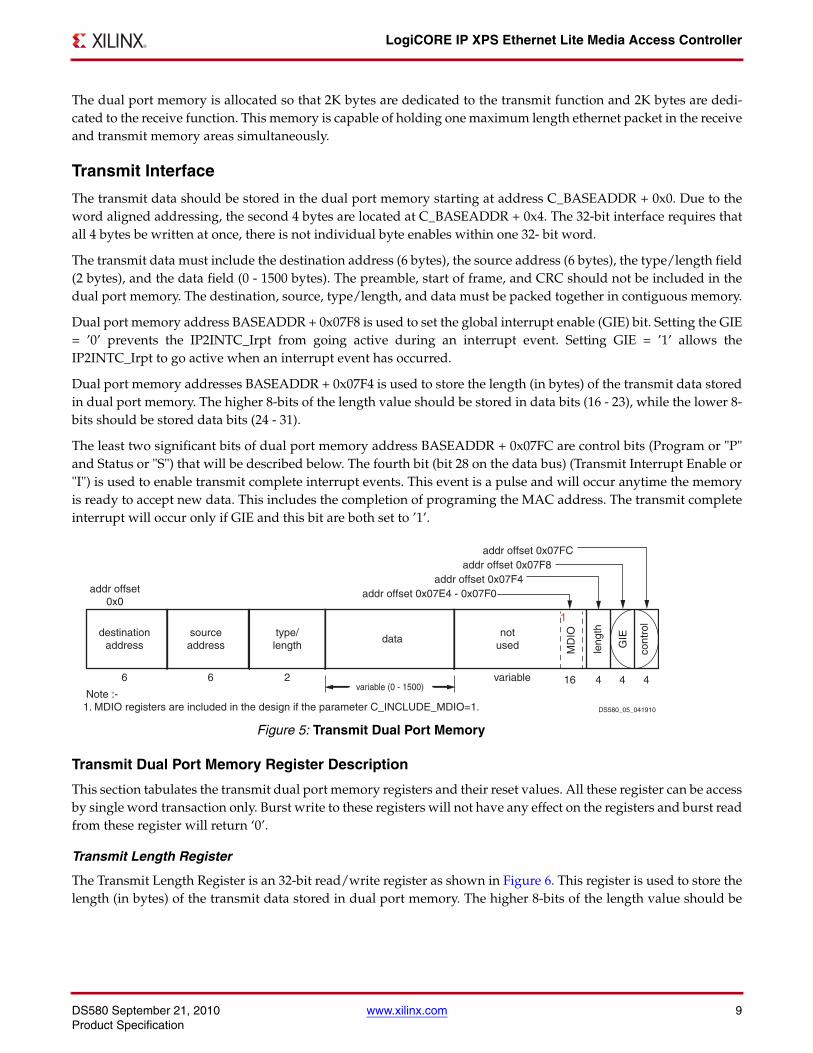
The transmit data should be stored in the dual port memory starting at address C_BASEADDR + 0x0. Due to theword aligned addressing, the second 4 bytes are located at C_BASEADDR + 0x4. The 32-bit interface requires thatall 4 bytes be written at once, there is not individual byte enables within one 32- bit word.
The transmit data must include the destination address (6 bytes), the source address (6 bytes), the type/length field(2 bytes), and the data field (0 - 1500 bytes). The preamble, start of frame, and CRC should not be included in thedual port memory. The destination, source, type/length, and data must be packed together in contiguous memory.
Dual port memory address BASEADDR + 0x07F8 is used to set the global interrupt enable (GIE) bit. Setting the GIE= ’0’ prevents the IP2INTC_Irpt from going active during an interrupt event. Setting GIE = ’1’ allows theIP2INTC_Irpt to go active when an interrupt event has occurred.
Dual port memory addresses BASEADDR + 0x07F4 is used to store the length (in bytes) of the transmit data storedin dual port memory. The higher 8-bits of the length value should be stored in data bits (16 - 23), while the lower 8-bits should be stored data bits (24 - 31).
The least two significant bits of dual port memory address BASEADDR + 0x07FC are control bits (Program or "P"and Status or "S") that will be described below. The fourth bit (bit 28 on the data bus) (Transmit Interrupt Enable or"I") is used to enable transmit complete interrupt events. This event is a pulse and will occur anytime the memoryis ready to accept new data. This includes the completion of programing the MAC address. The transmit completeinterrupt will occur only if GIE and this bit are both set to ’1’.
Transmit Dual Port Memory Register Description
This section tabulates the transmit dual port memory registers and their reset values. All these register can be accessby single word transaction only. Burst write to these registers will not have any effect on the registers and burst readfrom these register will return ‘0’.
Transmit Length Register
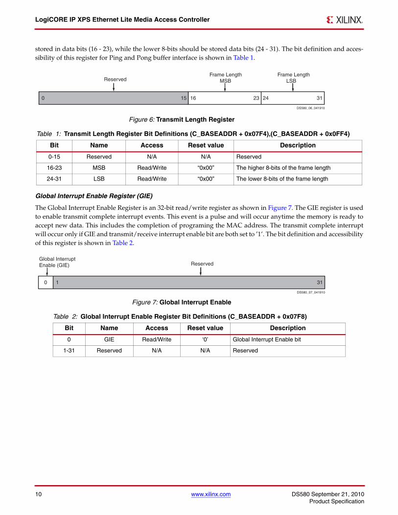
The Transmit Length Register is an 32-bit read/write register as shown in Figure 6. This register is used to store thelength (in bytes) of the transmit data stored in dual port memory. The higher 8-bits of the length value should be
X-Ref Target - Figure 5
Figure 5: Transmit Dual Port Memory
addr offset0x0
type/length
sourceaddress
datanot
useddestination
address GIE
cont
rol
leng
th
6 6 2 variablevariable (0 - 1500)
addr offset 0x07F4addr offset 0x07F8
addr offset 0x07FC
MD
IO
addr offset 0x07E4 - 0x07F0
16 4 44
1
Note :- 1. MDIO registers are included in the design if the parameter C_INCLUDE_MDIO=1. DS580_05_041910
LogiCORE IP XPS Ethernet Lite Media Access Controller
10 www.xilinx.com DS580 September 21, 2010Product Specification
stored in data bits (16 - 23), while the lower 8-bits should be stored data bits (24 - 31). The bit definition and acces-sibility of this register for Ping and Pong buffer interface is shown in Table 1.
Global Interrupt Enable Register (GIE)
The Global Interrupt Enable Register is an 32-bit read/write register as shown in Figure 7. The GIE register is usedto enable transmit complete interrupt events. This event is a pulse and will occur anytime the memory is ready toaccept new data. This includes the completion of programing the MAC address. The transmit complete interruptwill occur only if GIE and transmit/receive interrupt enable bit are both set to ’1’. The bit definition and accessibilityof this register is shown in Table 2.
X-Ref Target - Figure 6
Figure 6: Transmit Length Register
Table 1: Transmit Length Register Bit Definitions (C_BASEADDR + 0x07F4),(C_BASEADDR + 0x0FF4)
Bit Name Access Reset value Description
0-15 Reserved N/A N/A Reserved
16-23 MSB Read/Write “0x00” The higher 8-bits of the frame length
24-31 LSB Read/Write “0x00” The lower 8-bits of the frame length
X-Ref Target - Figure 7
Figure 7: Global Interrupt Enable
Table 2: Global Interrupt Enable Register Bit Definitions (C_BASEADDR + 0x07F8)
Bit Name Access Reset value Description
0 GIE Read/Write ‘0’ Global Interrupt Enable bit
1-31 Reserved N/A N/A Reserved
0 15 16 31
ReservedFrame Length LSB
Frame Length MSB
23 24
DS580_06_041910
0 1 31
Global Interrupt Enable (GIE) Reserved
DS580_07_041910
DS580 September 21, 2010 www.xilinx.com 11Product Specification
LogiCORE IP XPS Ethernet Lite Media Access Controller
Transmit Control Register (Ping)
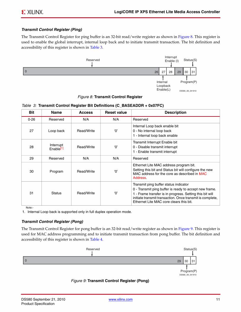
The Transmit Control Register for ping buffer is an 32-bit read/write register as shown in Figure 8. This register isused to enable the global interrupt, internal loop back and to initiate transmit transaction. The bit definition andaccessibility of this register is shown in Table 3.
Transmit Control Register (Pong)
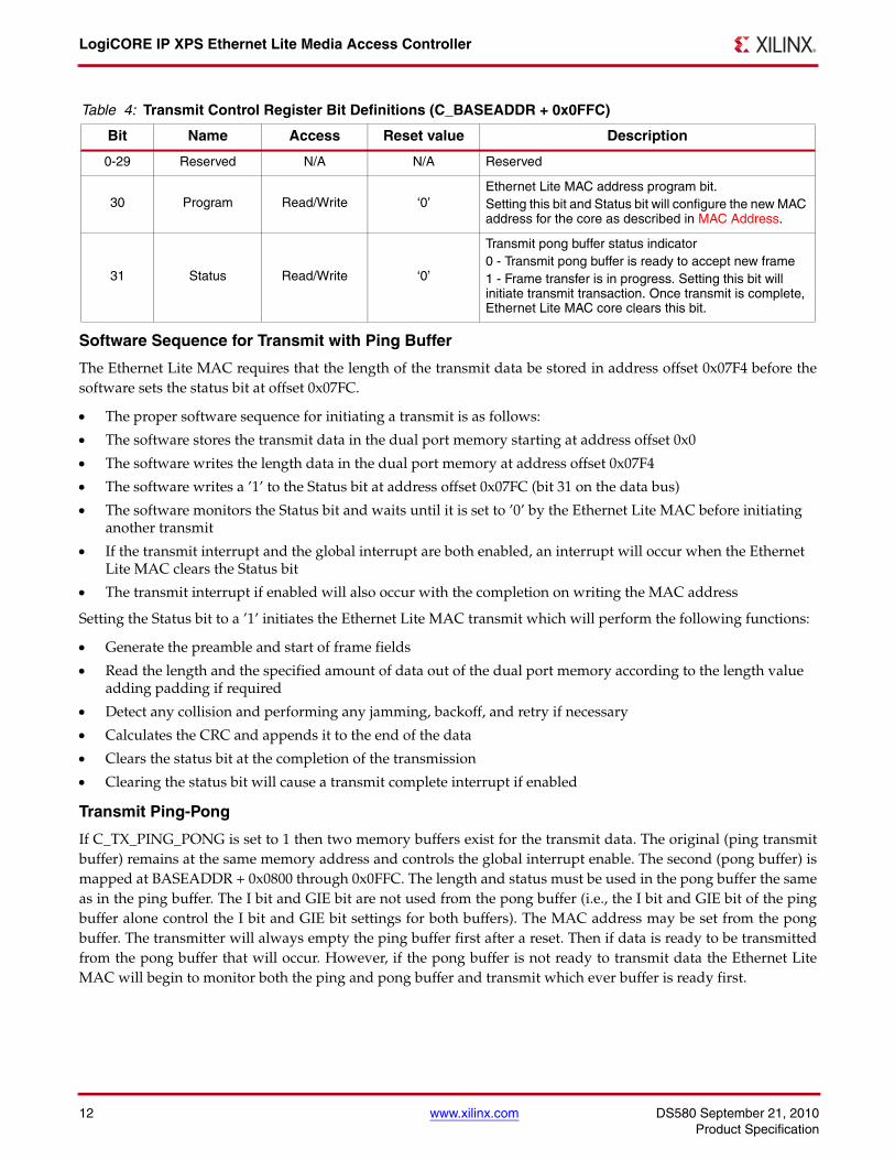
The Transmit Control Register for pong buffer is an 32-bit read/write register as shown in Figure 9. This register isused for MAC address programming and to initiate transmit transaction from pong buffer. The bit definition andaccessibility of this register is shown in Table 4.
X-Ref Target - Figure 8
Figure 8: Transmit Control Register
Table 3: Transmit Control Register Bit Definitions (C_BASEADDR + 0x07FC)
Bit Name Access Reset value Description
0-26 Reserved N/A N/A Reserved
27 Loop back Read/Write ‘0’Internal Loop back enable bit0 - No internal loop back1 - Internal loop back enable
28 Interrupt Enable[1] Read/Write ‘0’
Transmit Interrupt Enable bit0 - Disable transmit interrupt1 - Enable transmit interrupt
29 Reserved N/A N/A Reserved
30 Program Read/Write ‘0’
Ethernet Lite MAC address program bit. Setting this bit and Status bit will configure the new MAC address for the core as described in MAC Address.
31 Status Read/Write ‘0’
Transmit ping buffer status indicator 0 - Transmit ping buffer is ready to accept new frame.1 - Frame transfer is in progress. Setting this bit will initiate transmit transaction. Once transmit is complete, Ethernet Lite MAC core clears this bit.
Note:-
1. Internal Loop back is supported only in full duplex operation mode.
X-Ref Target - Figure 9
Figure 9: Transmit Control Register (Pong)
3126
Reserved Status(S)
Program(P)
302827 29
Interrupt Enable (I)
Internal LoopbackEnable(L)
0
DS580_08_041910
31
Reserved Status(S)
Program(P)
30290
DS580_09_041910
LogiCORE IP XPS Ethernet Lite Media Access Controller
12 www.xilinx.com DS580 September 21, 2010Product Specification
Software Sequence for Transmit with Ping Buffer
The Ethernet Lite MAC requires that the length of the transmit data be stored in address offset 0x07F4 before thesoftware sets the status bit at offset 0x07FC.
• The proper software sequence for initiating a transmit is as follows:
• The software stores the transmit data in the dual port memory starting at address offset 0x0
• The software writes the length data in the dual port memory at address offset 0x07F4
• The software writes a ’1’ to the Status bit at address offset 0x07FC (bit 31 on the data bus)
• The software monitors the Status bit and waits until it is set to ’0’ by the Ethernet Lite MAC before initiating another transmit
• If the transmit interrupt and the global interrupt are both enabled, an interrupt will occur when the Ethernet Lite MAC clears the Status bit
• The transmit interrupt if enabled will also occur with the completion on writing the MAC address
Setting the Status bit to a ’1’ initiates the Ethernet Lite MAC transmit which will perform the following functions:
• Generate the preamble and start of frame fields
• Read the length and the specified amount of data out of the dual port memory according to the length value adding padding if required
• Detect any collision and performing any jamming, backoff, and retry if necessary
• Calculates the CRC and appends it to the end of the data
• Clears the status bit at the completion of the transmission
• Clearing the status bit will cause a transmit complete interrupt if enabled
Transmit Ping-Pong
If C_TX_PING_PONG is set to 1 then two memory buffers exist for the transmit data. The original (ping transmitbuffer) remains at the same memory address and controls the global interrupt enable. The second (pong buffer) ismapped at BASEADDR + 0x0800 through 0x0FFC. The length and status must be used in the pong buffer the sameas in the ping buffer. The I bit and GIE bit are not used from the pong buffer (i.e., the I bit and GIE bit of the pingbuffer alone control the I bit and GIE bit settings for both buffers). The MAC address may be set from the pongbuffer. The transmitter will always empty the ping buffer first after a reset. Then if data is ready to be transmittedfrom the pong buffer that will occur. However, if the pong buffer is not ready to transmit data the Ethernet LiteMAC will begin to monitor both the ping and pong buffer and transmit which ever buffer is ready first.
Table 4: Transmit Control Register Bit Definitions (C_BASEADDR + 0x0FFC)
Bit Name Access Reset value Description
0-29 Reserved N/A N/A Reserved
30 Program Read/Write ‘0’Ethernet Lite MAC address program bit. Setting this bit and Status bit will configure the new MAC address for the core as described in MAC Address.
31 Status Read/Write ‘0’
Transmit pong buffer status indicator 0 - Transmit pong buffer is ready to accept new frame1 - Frame transfer is in progress. Setting this bit will initiate transmit transaction. Once transmit is complete, Ethernet Lite MAC core clears this bit.
DS580 September 21, 2010 www.xilinx.com 13Product Specification
LogiCORE IP XPS Ethernet Lite Media Access Controller
The proper software sequence for initiating a transmit with both a ping and pong buffer is as follows:
• The software stores the transmit data in the dual port memory starting at address offset 0x0
• The software writes the length data in the dual port memory at address offset 0x07F4
• The software writes a ’1’ to the Status bit at address offset 0x07FC (bit 31 on the data bus)
• The software may write to the pong buffer (0x0800 - 0x0FFC) at any time
• The software monitors the Status bit in the ping buffer and waits until it is set to ’0’, or waits for a transmit complete interrupt, before filling the ping buffer again
• If the transmit interrupt and the global interrupt are both enabled, an interrupt will occur when the Ethernet Lite MAC clears the Status bit
• The transmit interrupt if enabled will also occur with the completion of writing the MAC address
Setting the Status bit to a ’1’ initiates the Ethernet Lite MAC transmit which will perform the following functions:
• Generate the preamble and start of frame fields
• Read the length and the specified amount of data out of the dual port memory according to the length value adding padding if required
• Detect any collision and performing any jamming, backoff, and retry if necessary
• Calculates the CRC and appends it to the end of the data
• Clears the status bit at the completion of the transmission
• Clearing the status bit will cause a transmit complete interrupt if enabled
• The hardware will than transmit the pong buffer if it is available, or begin monitoring both ping and pong buffers until data is available
MAC Address
The 48-bit MAC address defaults at reset to 00-00-5E-00-FA-CE. This value can be changed by performing anaddress program operation via the transmit dual port memory.
The proper software sequence for programming a new MAC address is as follows:
• The software loads the new MAC address, in the transmit dual port memory starting at address offset 0x0. The most significant four bytes are stored at address offset 0x0 and the least significant two bytes are stored at address offset 0x4. The MAC address may also be programmed from the pong buffer starting at 0x0800
• The software writes a ’1’ to both the Program bit (bit 30 on the data bus) and the Status bit (bit 31 on the data bus) at address offset 0x07FC. The pong buffer address is 0x0FFC
• The software monitors the Status and Program bits and waits until they are set to ‘0’s before performing any additional ethernet operations
• A transmit complete interrupt, if enabled, will occur when the Status and Program bits are cleared
Receive Interface
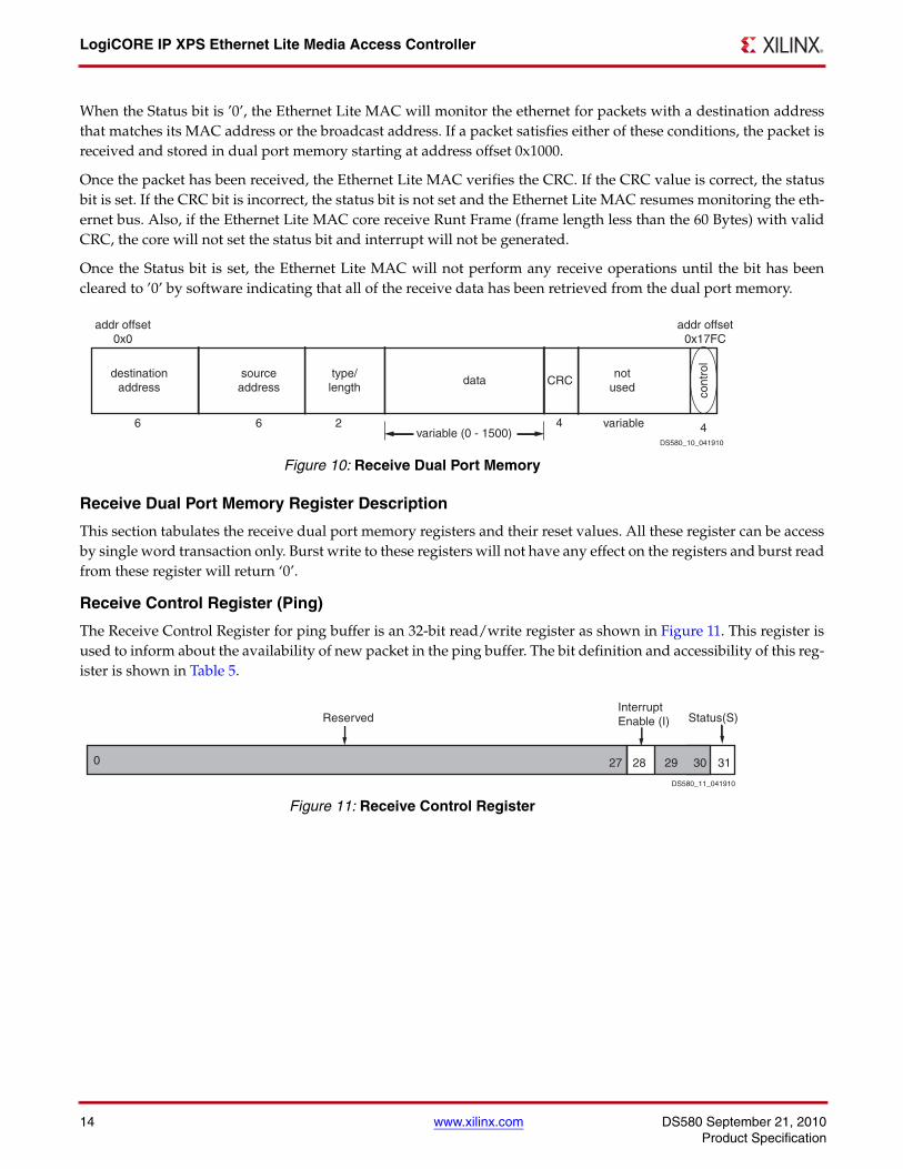
The entire received frame data from destination address to the end of the CRC is stored in the receive dual portmemory area which starts at address BASEADDR + 0x1000. The preamble and start of frame fields are not stored indual port memory.
Dual port memory address offset 0x17FC (bit 31 on the data bus) is used as a status to indicated the presence of areceive packet that is ready for processing by the software.
Dual port memory address offset 0x17FC (bit 28 on the data bus) is the Receive Interrupt enable. This event is apulse and will occur anytime the memory has data available. The receive complete interrupt will occur only if GIEand this bit are both set to ’1’.
LogiCORE IP XPS Ethernet Lite Media Access Controller
14 www.xilinx.com DS580 September 21, 2010Product Specification
When the Status bit is ’0’, the Ethernet Lite MAC will monitor the ethernet for packets with a destination addressthat matches its MAC address or the broadcast address. If a packet satisfies either of these conditions, the packet isreceived and stored in dual port memory starting at address offset 0x1000.
Once the packet has been received, the Ethernet Lite MAC verifies the CRC. If the CRC value is correct, the statusbit is set. If the CRC bit is incorrect, the status bit is not set and the Ethernet Lite MAC resumes monitoring the eth-ernet bus. Also, if the Ethernet Lite MAC core receive Runt Frame (frame length less than the 60 Bytes) with validCRC, the core will not set the status bit and interrupt will not be generated.
Once the Status bit is set, the Ethernet Lite MAC will not perform any receive operations until the bit has beencleared to ’0’ by software indicating that all of the receive data has been retrieved from the dual port memory.
Receive Dual Port Memory Register Description
This section tabulates the receive dual port memory registers and their reset values. All these register can be accessby single word transaction only. Burst write to these registers will not have any effect on the registers and burst readfrom these register will return ‘0’.
Receive Control Register (Ping)
The Receive Control Register for ping buffer is an 32-bit read/write register as shown in Figure 11. This register isused to inform about the availability of new packet in the ping buffer. The bit definition and accessibility of this reg-ister is shown in Table 5.
X-Ref Target - Figure 10
Figure 10: Receive Dual Port Memory
X-Ref Target - Figure 11
Figure 11: Receive Control Register
addr offset 0x0
addr offset0x17FC
type/ length
source address
data not
used destination
address
cont
rol
6 6 2 variablevariable (0 - 1500) 4
CRC
4
DS580_10_041910
31
Reserved Status(S)
302827 29
Interrupt Enable (I)
0
DS580_11_041910
DS580 September 21, 2010 www.xilinx.com 15Product Specification
LogiCORE IP XPS Ethernet Lite Media Access Controller
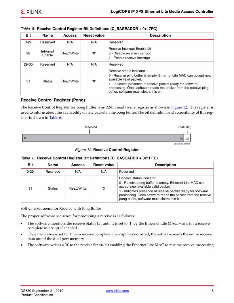
Receive Control Register (Pong)
The Receive Control Register for pong buffer is an 32-bit read/write register as shown in Figure 12. This register isused to inform about the availability of new packet in the pong buffer. The bit definition and accessibility of this reg-ister is shown in Table 6.
Software Sequence for Receive with Ping Buffer
The proper software sequence for processing a receive is as follows:
• The software monitors the receive Status bit until it is set to ’1’ by the Ethernet Lite MAC, waits for a receive complete interrupt if enabled
• Once the Status is set to ’1’, or a receive complete interrupt has occurred, the software reads the entire receive data out of the dual port memory
• The software writes a ’0’ to the receive Status bit enabling the Ethernet Lite MAC to resume receive processing
Table 5: Receive Control Register Bit Definitions (C_BASEADDR + 0x17FC)
Bit Name Access Reset value Description
0-27 Reserved N/A N/A Reserved
28 Interrupt Enable Read/Write ‘0’
Receive Interrupt Enable bit0 - Disable receive interrupt1 - Enable receive interrupt
29-30 Reserved N/A N/A Reserved
31 Status Read/Write ‘0’
Receive status indicator 0 - Receive ping buffer is empty. Ethernet Lite MAC can accept new available valid packet.1 - Indicates presence of receive packet ready for software processing. Once software reads the packet from the receive ping buffer, software must clears this bit.
X-Ref Target - Figure 12
Figure 12: Receive Control Register
Table 6: Receive Control Register Bit Definitions (C_BASEADDR + 0x1FFC)
Bit Name Access Reset value Description
0-30 Reserved N/A N/A Reserved
31 Status Read/Write ‘0’
Receive status indicator 0 - Receive pong buffer is empty. Ethernet Lite MAC can accept new available valid packet.1 - Indicates presence of receive packet ready for software processing. Once software reads the packet from the receive pong buffer, software must clears this bit.
31
Reserved Status(S)
300
DS580_12_041910

LogiCORE IP XPS Ethernet Lite Media Access Controller
16 www.xilinx.com DS580 September 21, 2010Product Specification
Receive Ping-Pong
If C_RX_PING_PONG is set to ’1’ then two memory buffers exist for the receive data. The original (ping receivebuffer) remains at the same memory location. The second (pong receiver buffer) is mapped at BASEADDR + 0x1800through 0x1FFC. Data is stored the same in the pong buffer as it is in the ping buffer.
The proper software sequence for processing a receive packet(s) with C_RX_PING_PONG = 1 is as follows:
• The software monitors the ping receive Status bit until it is set to ’1’ by the Ethernet Lite MAC, or waits for a receive complete interrupt if enabled
• Once the ping Status is set to ’1’, or a receive complete interrupt has occurred, the software reads the entire receive data out of the ping dual port memory
• The Ethernet Lite MAC will receive the next packet and store it in the pong receive buffer
• The software writes a ’0’ to the ping receive Status bit enabling the Ethernet Lite MAC to receive another packet in the ping receive buffer
• The software monitors the pong receive Status bit until it is set to ’1’ by the Ethernet Lite MAC, or waits for a receive complete interrupt if enabled
• Once the pong Status is set to ’1’, or a receive complete interrupt has occurred, the software reads the entire receive data out of the ping dual port memory
• The hardware will always write the first received packet after a reset to the ping buffer, the second received packet will be written to the pong buffer and the third received packet will be written to the ping buffer
Management Data Input/Output (MDIO) Master Interface Module
The Management Data Input/Output Master Interface module is included in the design if the parameterC_INCLUDE_MDIO = 1. Including this logic allows Ethernet Lite MAC core to access PHY configuration registers.The MDIO Master Interface module is designed to incorporate the features described in IEEE 802.3 Media Indepen-dent Interface (MII) specification.
The MDIO module generates management data clock to the PHY(PHY_MDC) with minimum period of 400 ns.PHY_MDC is sourced to PHY as timing reference for transfer of information on the PHY_MDIO (Management DataInput/Output) data signal.
PHY_MDIO is a bi-directional signal between the PHY and MDIO module. It is used to transfer control and statusinformation between the PHY and the MDIO module. The control information is driven by the MDIO module syn-chronously with respect to PHY_MDC and is sampled synchronously by the PHY. The status information is drivenby the PHY synchronously with respect to PHY_MDC and is sampled synchronously by the MDIO module.PHY_MDIO is driven through three-state circuit that enable either the MDIO module or the PHY to drive the cir-cuit.
The MDIO interface uses standard method to access PHY management registers. The MDIO module supports up to32 PHY devices. To access each PHY devices, the PHY device address must be written into the MIDO Address(MDIOADDR) register followed by PHY register address as shown in Figure 13. This module supports up 32 PHYmanagement registers access. The write transaction data for the PHY must be written into MDIO Write Data(MDIOWR) register and the status data from the PHY register can be read from MDIO Read Data (MDIORD) reg-ister. The MDIO Control (MDIOCTRL) register is used to initiate to management transaction on the MDIO lines.
MDIO Register Descriptions
This section tabulates the MDIO registers and their reset values. All these register can be access by single wordtransaction only. Burst write to these registers will not have any effect on the registers and burst read from these reg-ister will return ‘0’.
DS580 September 21, 2010 www.xilinx.com 17Product Specification
LogiCORE IP XPS Ethernet Lite Media Access Controller
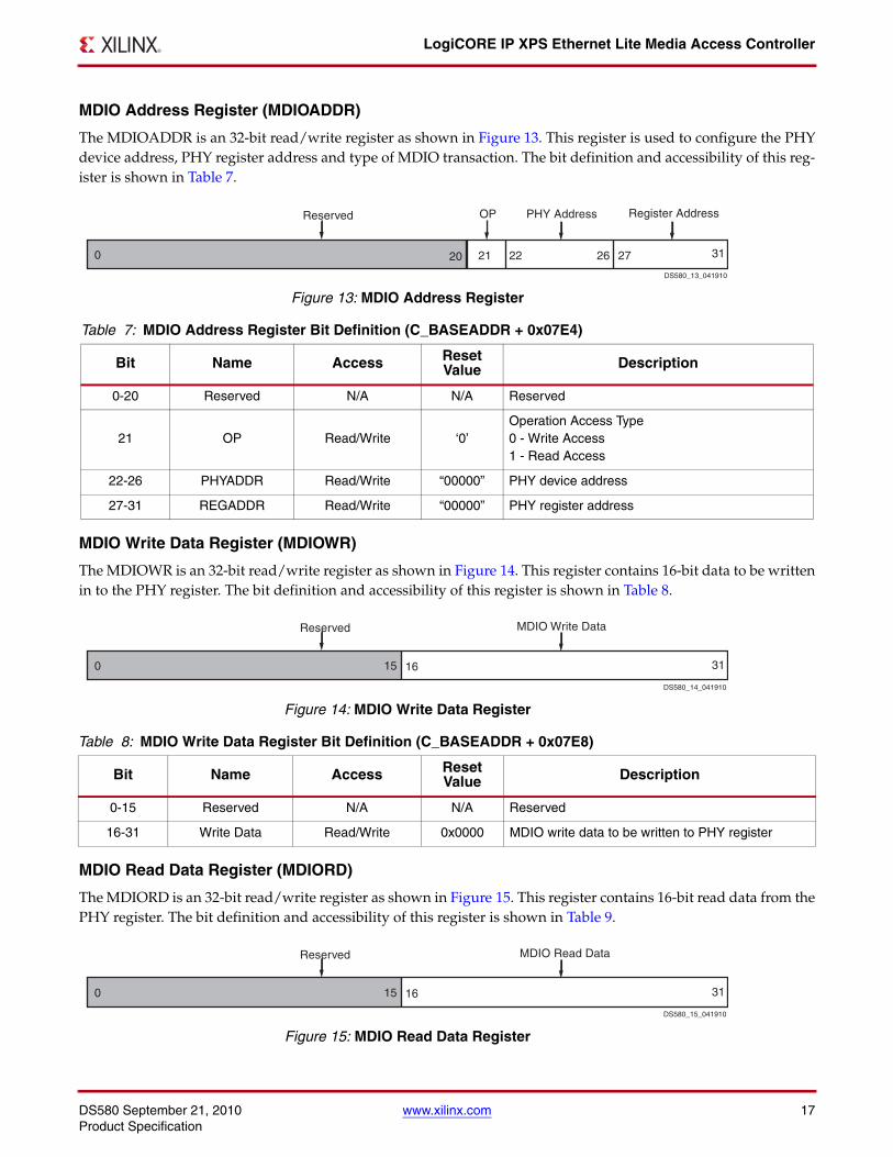
MDIO Address Register (MDIOADDR)
The MDIOADDR is an 32-bit read/write register as shown in Figure 13. This register is used to configure the PHYdevice address, PHY register address and type of MDIO transaction. The bit definition and accessibility of this reg-ister is shown in Table 7.
MDIO Write Data Register (MDIOWR)
The MDIOWR is an 32-bit read/write register as shown in Figure 14. This register contains 16-bit data to be writtenin to the PHY register. The bit definition and accessibility of this register is shown in Table 8.
MDIO Read Data Register (MDIORD)
The MDIORD is an 32-bit read/write register as shown in Figure 15. This register contains 16-bit read data from thePHY register. The bit definition and accessibility of this register is shown in Table 9.
X-Ref Target - Figure 13
Figure 13: MDIO Address Register
Table 7: MDIO Address Register Bit Definition (C_BASEADDR + 0x07E4)
Bit Name Access Reset Value Description
0-20 Reserved N/A N/A Reserved
21 OP Read/Write ‘0’Operation Access Type0 - Write Access1 - Read Access
22-26 PHYADDR Read/Write “00000” PHY device address
27-31 REGADDR Read/Write “00000” PHY register address
X-Ref Target - Figure 14
Figure 14: MDIO Write Data Register
Table 8: MDIO Write Data Register Bit Definition (C_BASEADDR + 0x07E8)
Bit Name Access Reset Value Description
0-15 Reserved N/A N/A Reserved
16-31 Write Data Read/Write 0x0000 MDIO write data to be written to PHY register
X-Ref Target - Figure 15
Figure 15: MDIO Read Data Register
2221 27 3126200
OPReserved PHY Address Register Address
DS580_13_041910
0 1615 31
Reserved MDIO Write Data
DS580_14_041910
0 1615 31
Reserved MDIO Read Data
DS580_15_041910
LogiCORE IP XPS Ethernet Lite Media Access Controller
18 www.xilinx.com DS580 September 21, 2010Product Specification
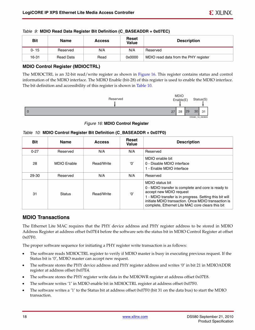
MDIO Control Register (MDIOCTRL)
The MDIOCTRL is an 32-bit read/write register as shown in Figure 16. This register contains status and controlinformation of the MDIO interface. The MDIO Enable (bit-28) of this register is used to enable the MDIO interface.The bit definition and accessibility of this register is shown in Table 10.
MDIO Transactions
The Ethernet Lite MAC requires that the PHY device address and PHY register address to be stored in MDIOAddress Register at address offset 0x07E4 before the software sets the status bit in MDIO Control Register at offset0x07F0.
The proper software sequence for initiating a PHY register write transaction is as follows:
• The software reads MDIOCTRL register to verify if MDIO master is busy in executing previous request. If the Status bit is ‘0’, MDIO master can accept new request.
• The software stores the PHY device address and PHY register address and writes ‘0’ in bit 21 in MDIOADDR register at address offset 0x07E4.
• The software stores the PHY register write data in the MDIOWR register at address offset 0x07E8.
• The software writes ‘1’ in MDIO enable bit in MDIOCTRL register at address offset 0x07F0.
• The software writes a ’1’ to the Status bit at address offset 0x07F0 (bit 31 on the data bus) to start the MDIO transaction.
Table 9: MDIO Read Data Register Bit Definition (C_BASEADDR + 0x07EC)
Bit Name Access Reset Value Description
0- 15 Reserved N/A N/A Reserved
16-31 Read Data Read 0x0000 MDIO read data from the PHY register
X-Ref Target - Figure 16
Figure 16: MDIO Control Register
Table 10: MDIO Control Register Bit Definition (C_BASEADDR + 0x07F0)
Bit Name Access Reset Value Description
0-27 Reserved N/A N/A Reserved
28 MDIO Enable Read/Write ‘0’MDIO enable bit0 - Disable MDIO interface1 - Enable MDIO interface
29-30 Reserved N/A N/A Reserved
31 Status Read/Write ‘0’
MDIO status bit0 - MDIO transfer is complete and core is ready to accept new MDIO request 1 - MDIO transfer is in progress. Setting this bit will initiate MDIO transaction. Once MDIO transaction is complete, Ethernet Lite MAC core clears this bit
0 3130
Reserved Status(S)
292827
MDIOEnable(E)
DS580_16_060809
DS580 September 21, 2010 www.xilinx.com 19Product Specification
LogiCORE IP XPS Ethernet Lite Media Access Controller
• After completing MDIO write transaction, Ethernet Lite MAC will clear the status bit.
• The software monitors the Status bit and waits until it is set to ’0’ by the Ethernet Lite MAC before initiating new transaction on MDIO lines.
• The proper software sequence for initiating a PHY register Read transaction is as follows:
• The software reads MDIOCTRL register to verify if MDIO master is busy in executing previous request. If the Status bit is ‘0’, MDIO master can accept new request.
• The software stores the PHY device address and PHY register address and writes ‘1’ in bit 21 in MDIOADDR register at address offset 0x07E4.
• The software writes ‘1’ in MDIO enable bit in MDIOCTRL register at address offset 0x07F0.
• The software writes a ’1’ to the Status bit at address offset 0x07F0 (bit 31 on the data bus) to start the MDIO transaction.
• After completing MDIO Read transaction, Ethernet Lite MAC will clear the status bit.
• The software monitors the Status bit and waits until it is set to ’0’ by the Ethernet Lite MAC before initiating new transaction on MDIO lines.
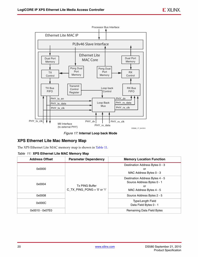
Internal Loop back Mode
The XPS Ethernet Lite MAC core can be configured in internal loop back mode when the parameterC_INCLUDE_INTERNAL_LOOPBACK is set to ‘1’ and by setting bit 27 of Transmit Control Register (Ping).Including the loop back logic uses BUFG for PHY clock switching. In this mode, the Ethernet Lite MAC core routeback data on TX lines on RX line. Loop back mode can be tested only in full duplex mode. In this mode, core doesnot accept any data from PHY and PHY_tx_clk and PHY_tx_en are used as PHY_rx_clk and PHY_dv internally asshown in Figure 17.
LogiCORE IP XPS Ethernet Lite Media Access Controller
20 www.xilinx.com DS580 September 21, 2010Product Specification
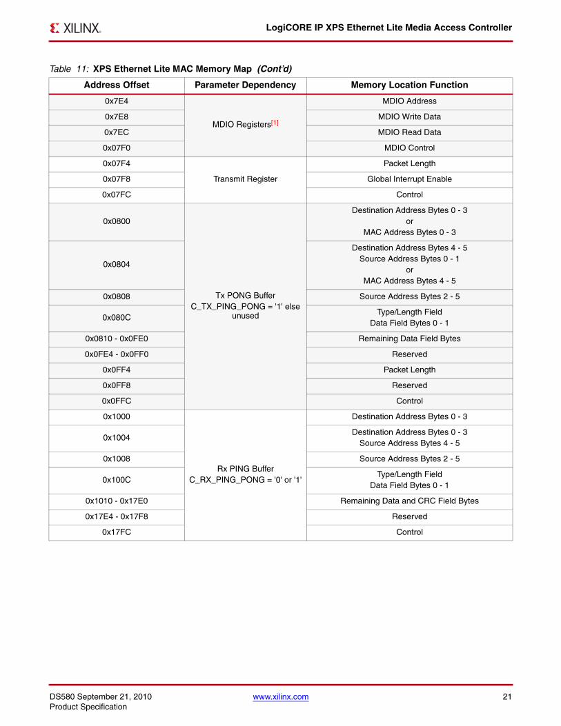
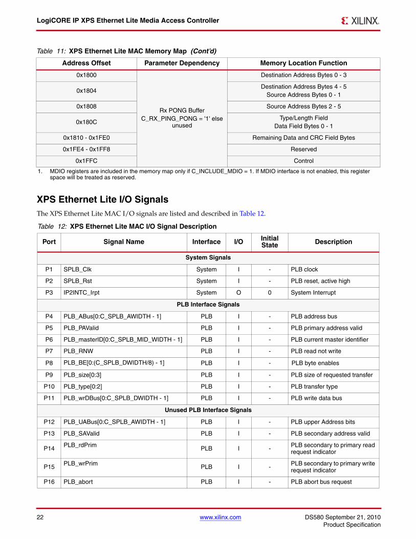
XPS Ethernet Lite Mac Memory Map
The XPS Ethernet Lite MAC memory map is shown in Table 11.
X-Ref Target - Figure 17
Figure 17: Internal Loop back Mode
Table 11: XPS Ethernet Lite MAC Memory Map
Address Offset Parameter Dependency Memory Location Function
0x0000
Tx PING BufferC_TX_PING_PONG = '0' or '1'
Destination Address Bytes 0 - 3or
MAC Address Bytes 0 - 3
0x0004
Destination Address Bytes 4 - 5Source Address Bytes 0 - 1
orMAC Address Bytes 4 - 5
0x0008 Source Address Bytes 2 - 5
0x000CType/Length Field
Data Field Bytes 0 - 1
0x0010 - 0x07E0 Remaining Data Field Bytes
TXControl
Dual PortMemory
RXControl
Dual PortMemory
TX BusFIFO
TransmitControlRegister
Loop BackMux
Pong DualPort
Memory
Pong DualPort
Memory
RX BusFIFO
PHY_tx_data
PHY_rx_data
Loop backControl
PHY_tx_clk PHY_rx_clk
PHY_rx_clk
PHY_rx_data
PHY_tx_clk
PHY_tx_en PHY_dv
PHY_dv
Ethernet Lite MAC Core
Ethernet Lite MAC IP
PLBv46 Slave Interface
Processor Bus Interface
MII Interface(to external PHY)
DS580_17_041910
DS580 September 21, 2010 www.xilinx.com 21Product Specification
LogiCORE IP XPS Ethernet Lite Media Access Controller
0x7E4
MDIO Registers[1]
MDIO Address
0x7E8 MDIO Write Data
0x7EC MDIO Read Data
0x07F0 MDIO Control
0x07F4
Transmit Register
Packet Length
0x07F8 Global Interrupt Enable
0x07FC Control
0x0800
Tx PONG BufferC_TX_PING_PONG = '1' else
unused
Destination Address Bytes 0 - 3or
MAC Address Bytes 0 - 3
0x0804
Destination Address Bytes 4 - 5Source Address Bytes 0 - 1
orMAC Address Bytes 4 - 5
0x0808 Source Address Bytes 2 - 5
0x080CType/Length Field
Data Field Bytes 0 - 1
0x0810 - 0x0FE0 Remaining Data Field Bytes
0x0FE4 - 0x0FF0 Reserved
0x0FF4 Packet Length
0x0FF8 Reserved
0x0FFC Control
0x1000
Rx PING BufferC_RX_PING_PONG = '0' or '1'
Destination Address Bytes 0 - 3
0x1004Destination Address Bytes 0 - 3
Source Address Bytes 4 - 5
0x1008 Source Address Bytes 2 - 5
0x100CType/Length Field
Data Field Bytes 0 - 1
0x1010 - 0x17E0 Remaining Data and CRC Field Bytes
0x17E4 - 0x17F8 Reserved
0x17FC Control
Table 11: XPS Ethernet Lite MAC Memory Map (Cont’d)
Address Offset Parameter Dependency Memory Location Function
LogiCORE IP XPS Ethernet Lite Media Access Controller
22 www.xilinx.com DS580 September 21, 2010Product Specification
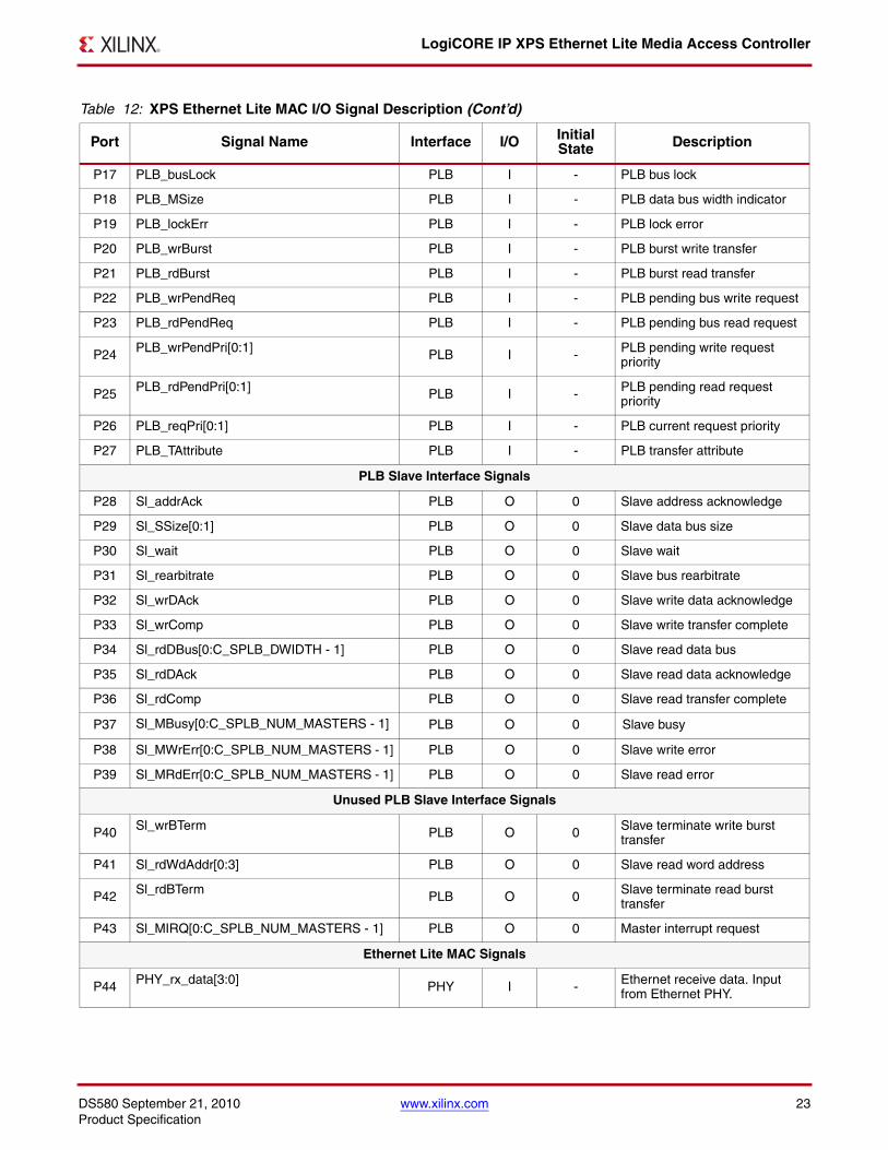
XPS Ethernet Lite I/O SignalsThe XPS Ethernet Lite MAC I/O signals are listed and described in Table 12.
0x1800
Rx PONG BufferC_RX_PING_PONG = '1' else
unused
Destination Address Bytes 0 - 3
0x1804Destination Address Bytes 4 - 5
Source Address Bytes 0 - 1
0x1808 Source Address Bytes 2 - 5
0x180CType/Length Field
Data Field Bytes 0 - 1
0x1810 - 0x1FE0 Remaining Data and CRC Field Bytes
0x1FE4 - 0x1FF8 Reserved
0x1FFC Control
1. MDIO registers are included in the memory map only if C_INCLUDE_MDIO = 1. If MDIO interface is not enabled, this register space will be treated as reserved.
Table 12: XPS Ethernet Lite MAC I/O Signal Description
Port Signal Name Interface I/O Initial State Description
System Signals
P1 SPLB_Clk System I - PLB clock
P2 SPLB_Rst System I - PLB reset, active high
P3 IP2INTC_Irpt System O 0 System Interrupt
PLB Interface Signals
P4 PLB_ABus[0:C_SPLB_AWIDTH - 1] PLB I - PLB address bus
P5 PLB_PAValid PLB I - PLB primary address valid
P6 PLB_masterID[0:C_SPLB_MID_WIDTH - 1] PLB I - PLB current master identifier
P7 PLB_RNW PLB I - PLB read not write
P8 PLB_BE[0:(C_SPLB_DWIDTH/8) - 1] PLB I - PLB byte enables
P9 PLB_size[0:3] PLB I - PLB size of requested transfer
P10 PLB_type[0:2] PLB I - PLB transfer type
P11 PLB_wrDBus[0:C_SPLB_DWIDTH - 1] PLB I - PLB write data bus
Unused PLB Interface Signals
P12 PLB_UABus[0:C_SPLB_AWIDTH - 1] PLB I - PLB upper Address bits
P13 PLB_SAValid PLB I - PLB secondary address valid
P14 PLB_rdPrim PLB I - PLB secondary to primary read request indicator
P15 PLB_wrPrim PLB I - PLB secondary to primary write request indicator
P16 PLB_abort PLB I - PLB abort bus request
Table 11: XPS Ethernet Lite MAC Memory Map (Cont’d)
Address Offset Parameter Dependency Memory Location Function
DS580 September 21, 2010 www.xilinx.com 23Product Specification
LogiCORE IP XPS Ethernet Lite Media Access Controller
P17 PLB_busLock PLB I - PLB bus lock
P18 PLB_MSize PLB I - PLB data bus width indicator
P19 PLB_lockErr PLB I - PLB lock error
P20 PLB_wrBurst PLB I - PLB burst write transfer
P21 PLB_rdBurst PLB I - PLB burst read transfer
P22 PLB_wrPendReq PLB I - PLB pending bus write request
P23 PLB_rdPendReq PLB I - PLB pending bus read request
P24 PLB_wrPendPri[0:1] PLB I - PLB pending write request priority
P25 PLB_rdPendPri[0:1] PLB I - PLB pending read request priority
P26 PLB_reqPri[0:1] PLB I - PLB current request priority
P27 PLB_TAttribute PLB I - PLB transfer attribute
PLB Slave Interface Signals
P28 Sl_addrAck PLB O 0 Slave address acknowledge
P29 Sl_SSize[0:1] PLB O 0 Slave data bus size
P30 Sl_wait PLB O 0 Slave wait
P31 Sl_rearbitrate PLB O 0 Slave bus rearbitrate
P32 Sl_wrDAck PLB O 0 Slave write data acknowledge
P33 Sl_wrComp PLB O 0 Slave write transfer complete
P34 Sl_rdDBus[0:C_SPLB_DWIDTH - 1] PLB O 0 Slave read data bus
P35 Sl_rdDAck PLB O 0 Slave read data acknowledge
P36 Sl_rdComp PLB O 0 Slave read transfer complete
P37 Sl_MBusy[0:C_SPLB_NUM_MASTERS - 1] PLB O 0 Slave busy
P38 Sl_MWrErr[0:C_SPLB_NUM_MASTERS - 1] PLB O 0 Slave write error
P39 Sl_MRdErr[0:C_SPLB_NUM_MASTERS - 1] PLB O 0 Slave read error
Unused PLB Slave Interface Signals
P40 Sl_wrBTerm PLB O 0 Slave terminate write burst transfer
P41 Sl_rdWdAddr[0:3] PLB O 0 Slave read word address
P42 Sl_rdBTerm PLB O 0 Slave terminate read burst transfer
P43 Sl_MIRQ[0:C_SPLB_NUM_MASTERS - 1] PLB O 0 Master interrupt request
Ethernet Lite MAC Signals
P44 PHY_rx_data[3:0] PHY I - Ethernet receive data. Input from Ethernet PHY.
Table 12: XPS Ethernet Lite MAC I/O Signal Description (Cont’d)
Port Signal Name Interface I/O Initial State Description
LogiCORE IP XPS Ethernet Lite Media Access Controller
24 www.xilinx.com DS580 September 21, 2010Product Specification
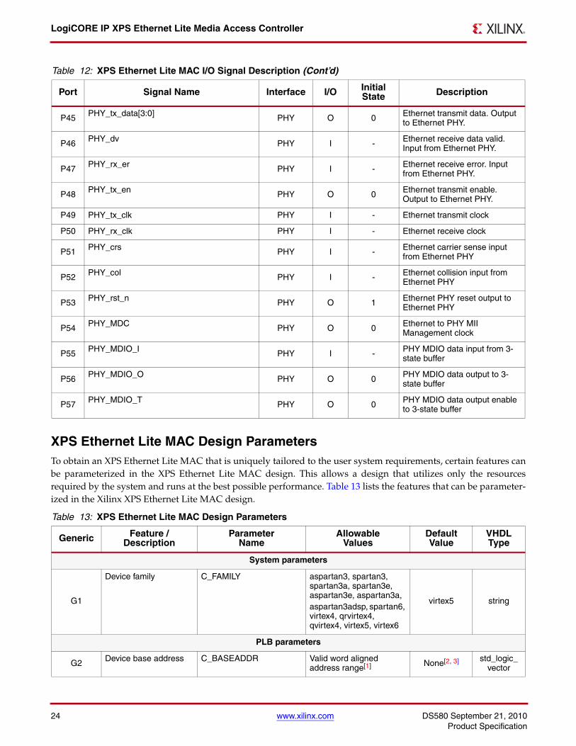
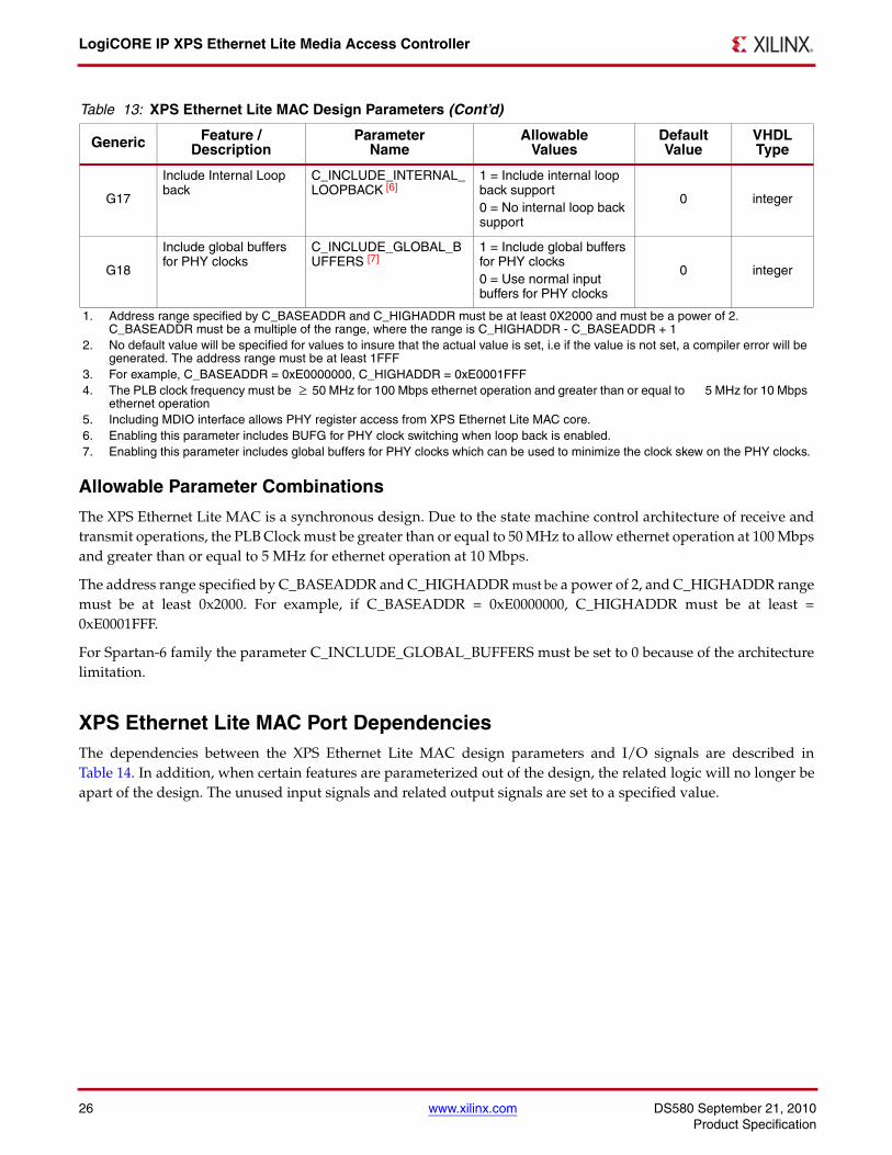
XPS Ethernet Lite MAC Design ParametersTo obtain an XPS Ethernet Lite MAC that is uniquely tailored to the user system requirements, certain features canbe parameterized in the XPS Ethernet Lite MAC design. This allows a design that utilizes only the resourcesrequired by the system and runs at the best possible performance. Table 13 lists the features that can be parameter-ized in the Xilinx XPS Ethernet Lite MAC design.
P45 PHY_tx_data[3:0] PHY O 0 Ethernet transmit data. Output to Ethernet PHY.
P46 PHY_dv PHY I - Ethernet receive data valid. Input from Ethernet PHY.
P47 PHY_rx_er PHY I - Ethernet receive error. Input from Ethernet PHY.
P48 PHY_tx_en PHY O 0 Ethernet transmit enable. Output to Ethernet PHY.
P49 PHY_tx_clk PHY I - Ethernet transmit clock
P50 PHY_rx_clk PHY I - Ethernet receive clock
P51 PHY_crs PHY I - Ethernet carrier sense input from Ethernet PHY
P52 PHY_col PHY I - Ethernet collision input from Ethernet PHY
P53 PHY_rst_n PHY O 1 Ethernet PHY reset output to Ethernet PHY
P54 PHY_MDC PHY O 0 Ethernet to PHY MII Management clock
P55 PHY_MDIO_I PHY I - PHY MDIO data input from 3-state buffer
P56 PHY_MDIO_O PHY O 0 PHY MDIO data output to 3-state buffer
P57 PHY_MDIO_T PHY O 0 PHY MDIO data output enable to 3-state buffer
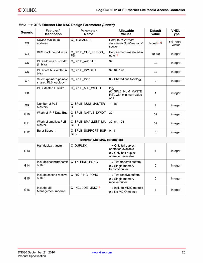
Table 13: XPS Ethernet Lite MAC Design Parameters
Generic Feature / Description
ParameterName
AllowableValues
DefaultValue
VHDLType
System parameters
G1
Device family C_FAMILY aspartan3, spartan3, spartan3a, spartan3e, aspartan3e, aspartan3a, aspartan3adsp, spartan6, virtex4, qrvirtex4, qvirtex4, virtex5, virtex6
virtex5 string
PLB parameters
G2 Device base address C_BASEADDR Valid word aligned address range[1] None[2, 3] std_logic_
vector
Table 12: XPS Ethernet Lite MAC I/O Signal Description (Cont’d)
Port Signal Name Interface I/O Initial State Description
DS580 September 21, 2010 www.xilinx.com 25Product Specification
LogiCORE IP XPS Ethernet Lite Media Access Controller
G3Device maximum address
C_HIGHADDR Refer to “Allowable Parameter Combinations” section
None[2, 3] std_logic_ vector
G4 BUS clock period in ps C_SPLB_CLK_PERIOD_PS
Requirements as stated in note [4] 10000 integer
G5 PLB address bus width (in bits)
C_SPLB_AWIDTH 32 32 integer
G6 PLB data bus width (in bits)
C_SPLB_DWIDTH 32, 64, 128 32 integer
G7 Selects point-to-point or shared PLB topology
C_SPLB_P2P 0 = Shared bus topology 0 integer
G8
PLB Master ID width C_SPLB_MID_WIDTH log2 (C_SPLB_NUM_MASTERS), with minimum value of 1
1 integer
G9 Number of PLB Masters
C_SPLB_NUM_MASTERS
1 - 16 1 integer
G10 Width of IPIF Data Bus C_SPLB_NATIVE_DWIDTH
32 32 integer
G11 Width of smallest PLB Master
C_SPLB_SMALLEST_MASTER
32, 64, 128 32 integer
G12 Burst Support C_SPLB_SUPPORT_BURSTS
0 - 1 0 integer
Ethernet Lite MAC parameters
G13
Half duplex transmit C_DUPLEX 1 = Only full duplex operation available0 = Only half duplex operation available
1 integer
G14Include second transmit buffer
C_TX_PING_PONG 1 = Two transmit buffers0 = Single memory transmit buffer
0 integer
G15Include second receive buffer
C_RX_PING_PONG 1 = Two receive buffers0 = Single memory receive buffer
0 integer
G16Include MII Management module
C_INCLUDE_MDIO [5] 1 = Include MDIO module0 = No MDIO module
1 integer
Table 13: XPS Ethernet Lite MAC Design Parameters (Cont’d)
Generic Feature / Description
ParameterName
AllowableValues
DefaultValue
VHDLType
LogiCORE IP XPS Ethernet Lite Media Access Controller
26 www.xilinx.com DS580 September 21, 2010Product Specification
Allowable Parameter Combinations
The XPS Ethernet Lite MAC is a synchronous design. Due to the state machine control architecture of receive andtransmit operations, the PLB Clock must be greater than or equal to 50 MHz to allow ethernet operation at 100 Mbpsand greater than or equal to 5 MHz for ethernet operation at 10 Mbps.
The address range specified by C_BASEADDR and C_HIGHADDR must be a power of 2, and C_HIGHADDR rangemust be at least 0x2000. For example, if C_BASEADDR = 0xE0000000, C_HIGHADDR must be at least =0xE0001FFF.
For Spartan-6 family the parameter C_INCLUDE_GLOBAL_BUFFERS must be set to 0 because of the architecturelimitation.
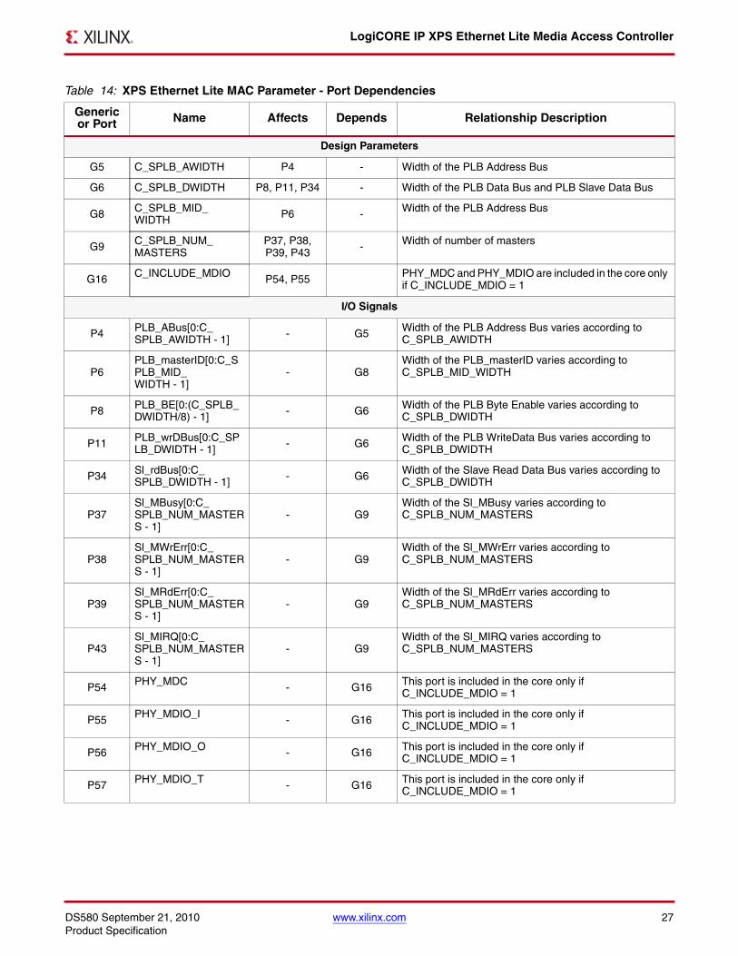
XPS Ethernet Lite MAC Port DependenciesThe dependencies between the XPS Ethernet Lite MAC design parameters and I/O signals are described inTable 14. In addition, when certain features are parameterized out of the design, the related logic will no longer beapart of the design. The unused input signals and related output signals are set to a specified value.
G17
Include Internal Loop back
C_INCLUDE_INTERNAL_LOOPBACK [6]
1 = Include internal loop back support0 = No internal loop back support
0 integer
G18
Include global buffers for PHY clocks
C_INCLUDE_GLOBAL_BUFFERS [7]
1 = Include global buffers for PHY clocks0 = Use normal input buffers for PHY clocks
0 integer
1. Address range specified by C_BASEADDR and C_HIGHADDR must be at least 0X2000 and must be a power of 2. C_BASEADDR must be a multiple of the range, where the range is C_HIGHADDR - C_BASEADDR + 1
2. No default value will be specified for values to insure that the actual value is set, i.e if the value is not set, a compiler error will be generated. The address range must be at least 1FFF
3. For example, C_BASEADDR = 0xE0000000, C_HIGHADDR = 0xE0001FFF4. The PLB clock frequency must be 50 MHz for 100 Mbps ethernet operation and greater than or equal to 5 MHz for 10 Mbps
ethernet operation5. Including MDIO interface allows PHY register access from XPS Ethernet Lite MAC core.6. Enabling this parameter includes BUFG for PHY clock switching when loop back is enabled.7. Enabling this parameter includes global buffers for PHY clocks which can be used to minimize the clock skew on the PHY clocks.
Table 13: XPS Ethernet Lite MAC Design Parameters (Cont’d)
Generic Feature / Description
ParameterName
AllowableValues
DefaultValue
VHDLType
≥
DS580 September 21, 2010 www.xilinx.com 27Product Specification
LogiCORE IP XPS Ethernet Lite Media Access Controller
Table 14: XPS Ethernet Lite MAC Parameter - Port Dependencies
Genericor Port Name Affects Depends Relationship Description
Design Parameters
G5 C_SPLB_AWIDTH P4 - Width of the PLB Address Bus
G6 C_SPLB_DWIDTH P8, P11, P34 - Width of the PLB Data Bus and PLB Slave Data Bus
G8 C_SPLB_MID_WIDTH P6 - Width of the PLB Address Bus
G9 C_SPLB_NUM_MASTERS
P37, P38, P39, P43 - Width of number of masters
G16 C_INCLUDE_MDIO P54, P55 PHY_MDC and PHY_MDIO are included in the core only if C_INCLUDE_MDIO = 1
I/O Signals
P4 PLB_ABus[0:C_SPLB_AWIDTH - 1] - G5 Width of the PLB Address Bus varies according to
C_SPLB_AWIDTH
P6PLB_masterID[0:C_SPLB_MID_WIDTH - 1]
- G8Width of the PLB_masterID varies according to C_SPLB_MID_WIDTH
P8 PLB_BE[0:(C_SPLB_DWIDTH/8) - 1] - G6 Width of the PLB Byte Enable varies according to
C_SPLB_DWIDTH
P11 PLB_wrDBus[0:C_SPLB_DWIDTH - 1] - G6 Width of the PLB WriteData Bus varies according to
C_SPLB_DWIDTH
P34 Sl_rdBus[0:C_SPLB_DWIDTH - 1] - G6 Width of the Slave Read Data Bus varies according to
C_SPLB_DWIDTH
P37Sl_MBusy[0:C_SPLB_NUM_MASTERS - 1]
- G9Width of the Sl_MBusy varies according to C_SPLB_NUM_MASTERS
P38Sl_MWrErr[0:C_SPLB_NUM_MASTERS - 1]
- G9Width of the Sl_MWrErr varies according to C_SPLB_NUM_MASTERS
P39Sl_MRdErr[0:C_SPLB_NUM_MASTERS - 1]
- G9Width of the Sl_MRdErr varies according to C_SPLB_NUM_MASTERS
P43Sl_MIRQ[0:C_SPLB_NUM_MASTERS - 1]
- G9Width of the Sl_MIRQ varies according to C_SPLB_NUM_MASTERS
P54 PHY_MDC - G16 This port is included in the core only if C_INCLUDE_MDIO = 1
P55 PHY_MDIO_I - G16 This port is included in the core only if C_INCLUDE_MDIO = 1
P56 PHY_MDIO_O - G16 This port is included in the core only if C_INCLUDE_MDIO = 1
P57 PHY_MDIO_T - G16 This port is included in the core only if C_INCLUDE_MDIO = 1
LogiCORE IP XPS Ethernet Lite Media Access Controller
28 www.xilinx.com DS580 September 21, 2010Product Specification
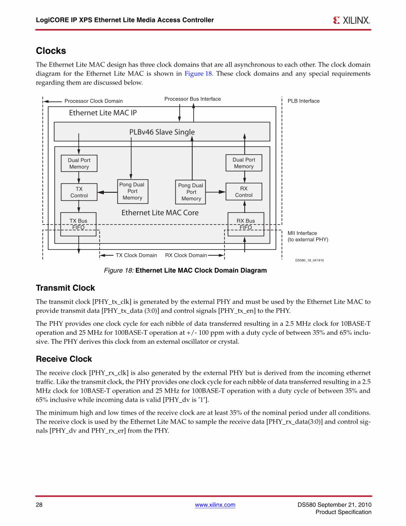
ClocksThe Ethernet Lite MAC design has three clock domains that are all asynchronous to each other. The clock domaindiagram for the Ethernet Lite MAC is shown in Figure 18. These clock domains and any special requirementsregarding them are discussed below.
Transmit Clock
The transmit clock [PHY_tx_clk] is generated by the external PHY and must be used by the Ethernet Lite MAC toprovide transmit data [PHY_tx_data (3:0)] and control signals [PHY_tx_en] to the PHY.
The PHY provides one clock cycle for each nibble of data transferred resulting in a 2.5 MHz clock for 10BASE-Toperation and 25 MHz for 100BASE-T operation at +/- 100 ppm with a duty cycle of between 35% and 65% inclu-sive. The PHY derives this clock from an external oscillator or crystal.
Receive Clock
The receive clock [PHY_rx_clk] is also generated by the external PHY but is derived from the incoming ethernettraffic. Like the transmit clock, the PHY provides one clock cycle for each nibble of data transferred resulting in a 2.5MHz clock for 10BASE-T operation and 25 MHz for 100BASE-T operation with a duty cycle of between 35% and65% inclusive while incoming data is valid [PHY_dv is ’1’].
The minimum high and low times of the receive clock are at least 35% of the nominal period under all conditions.The receive clock is used by the Ethernet Lite MAC to sample the receive data [PHY_rx_data(3:0)] and control sig-nals [PHY_dv and PHY_rx_er] from the PHY.
X-Ref Target - Figure 18
Figure 18: Ethernet Lite MAC Clock Domain Diagram
TXControl
Dual PortMemory
Pong Dual Port
Memory
Pong Dual Port
Memory
RXControl
Dual PortMemory
TX BusFIFO
RX BusFIFO
TX Clock Domain RX Clock Domain
Ethernet Lite MAC Core
Ethernet Lite MAC IP
PLBv46 Slave Single
Processor Clock Domain Processor Bus Interface PLB Interface
MII Interface(to external PHY)
DS580_18_041910
DS580 September 21, 2010 www.xilinx.com 29Product Specification
LogiCORE IP XPS Ethernet Lite Media Access Controller
Processor Bus Clock
The majority of the Ethernet Lite MAC operation functions in the processor bus clock domain. This clock must begreater than or equal to 50 MHz in order to transmit and receive ethernet data at 100 Mbps and greater than or equalto 5 MHz in order to transmit and receive ethernet data at 10 Mbps.
PHY Interface Signals
PHY_rst_n
Many PHY devices require that they be held in reset for some period after power becomes valid in order for thePHY device to be operational following the power-up sequence. The PHY_rst_n signal is an active low reset whichis tied directly to the PLB reset signal (SPLB_Rst). This output signal may be connected to the active low reset inputof a PHY device.
PHY_tx_en
The Ethernet Lite MAC uses the Transmit Enable signal (PHY_tx_en) to indicate to the PHY that it is providing nib-bles at the MII interface for transmission. It is asserted synchronously to PHY_tx_clk with the first nibble of the pre-amble and remains asserted while all nibbles have been transmitted. PHY_tx_en is negated prior to the firstPHY_tx_clk following the final nibble of a frame.
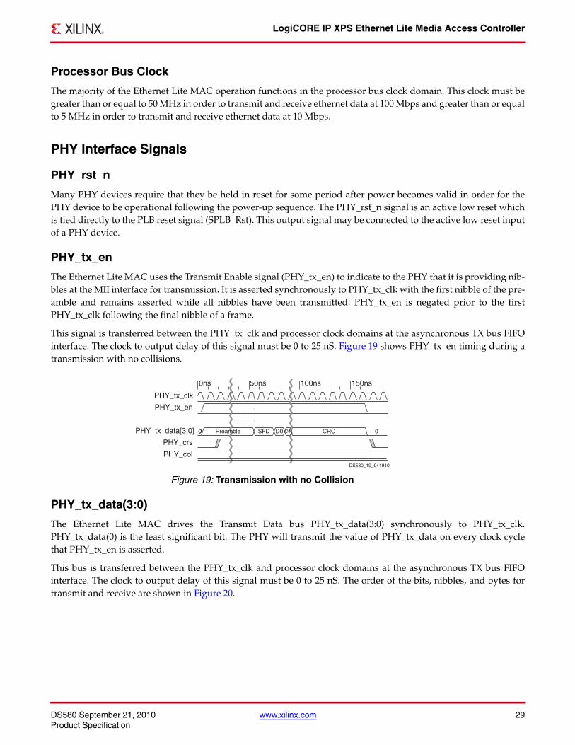
This signal is transferred between the PHY_tx_clk and processor clock domains at the asynchronous TX bus FIFOinterface. The clock to output delay of this signal must be 0 to 25 nS. Figure 19 shows PHY_tx_en timing during atransmission with no collisions.
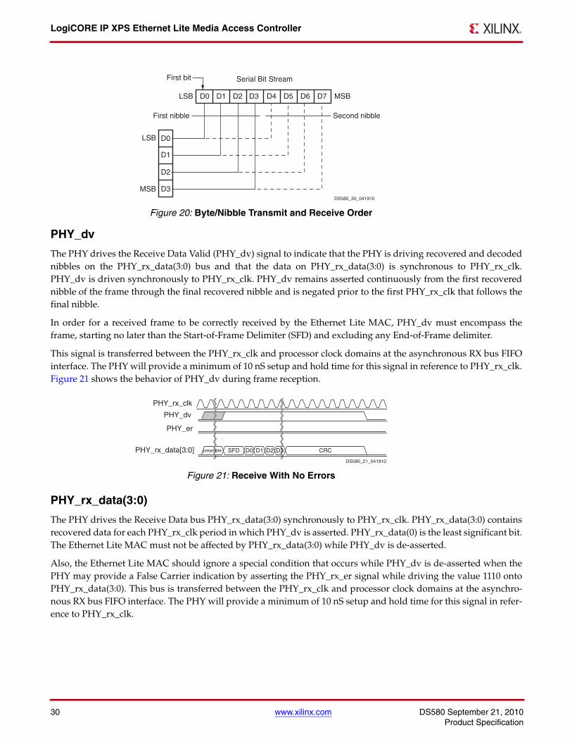
PHY_tx_data(3:0)
The Ethernet Lite MAC drives the Transmit Data bus PHY_tx_data(3:0) synchronously to PHY_tx_clk.PHY_tx_data(0) is the least significant bit. The PHY will transmit the value of PHY_tx_data on every clock cyclethat PHY_tx_en is asserted.
This bus is transferred between the PHY_tx_clk and processor clock domains at the asynchronous TX bus FIFOinterface. The clock to output delay of this signal must be 0 to 25 nS. The order of the bits, nibbles, and bytes fortransmit and receive are shown in Figure 20.
X-Ref Target - Figure 19
Figure 19: Transmission with no Collision
0ns 50ns 100ns 150ns
PHY_tx_clk
PHY_tx_en
PHY_tx_data[3:0]
PHY_crs
PHY_col
0 0 Preamble SFD D0 D1 CRC 0
DS580_19_041910
LogiCORE IP XPS Ethernet Lite Media Access Controller
30 www.xilinx.com DS580 September 21, 2010Product Specification
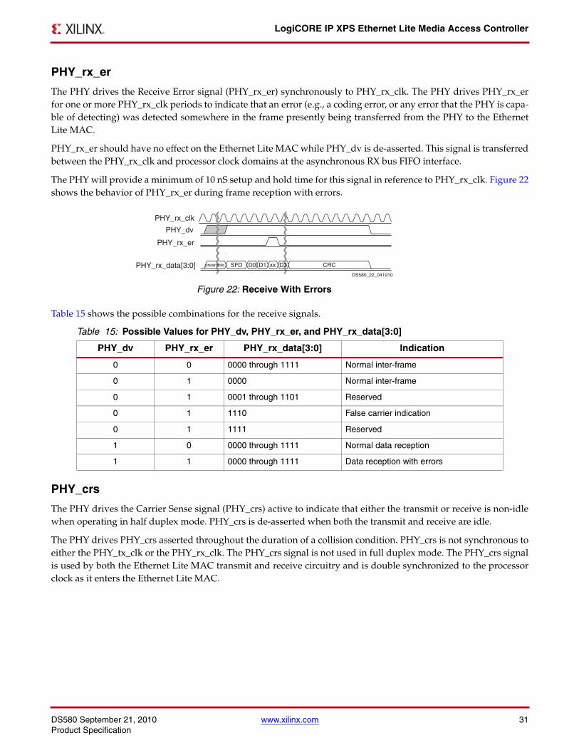
PHY_dv
The PHY drives the Receive Data Valid (PHY_dv) signal to indicate that the PHY is driving recovered and decodednibbles on the PHY_rx_data(3:0) bus and that the data on PHY_rx_data(3:0) is synchronous to PHY_rx_clk.PHY_dv is driven synchronously to PHY_rx_clk. PHY_dv remains asserted continuously from the first recoverednibble of the frame through the final recovered nibble and is negated prior to the first PHY_rx_clk that follows thefinal nibble.
In order for a received frame to be correctly received by the Ethernet Lite MAC, PHY_dv must encompass theframe, starting no later than the Start-of-Frame Delimiter (SFD) and excluding any End-of-Frame delimiter.
This signal is transferred between the PHY_rx_clk and processor clock domains at the asynchronous RX bus FIFOinterface. The PHY will provide a minimum of 10 nS setup and hold time for this signal in reference to PHY_rx_clk.Figure 21 shows the behavior of PHY_dv during frame reception.
PHY_rx_data(3:0)
The PHY drives the Receive Data bus PHY_rx_data(3:0) synchronously to PHY_rx_clk. PHY_rx_data(3:0) containsrecovered data for each PHY_rx_clk period in which PHY_dv is asserted. PHY_rx_data(0) is the least significant bit.The Ethernet Lite MAC must not be affected by PHY_rx_data(3:0) while PHY_dv is de-asserted.
Also, the Ethernet Lite MAC should ignore a special condition that occurs while PHY_dv is de-asserted when thePHY may provide a False Carrier indication by asserting the PHY_rx_er signal while driving the value 1110 ontoPHY_rx_data(3:0). This bus is transferred between the PHY_rx_clk and processor clock domains at the asynchro-nous RX bus FIFO interface. The PHY will provide a minimum of 10 nS setup and hold time for this signal in refer-ence to PHY_rx_clk.
X-Ref Target - Figure 20
Figure 20: Byte/Nibble Transmit and Receive Order
X-Ref Target - Figure 21
Figure 21: Receive With No Errors
Serial Bit Stream First bit
D4 D5 D6 D7 LSB MSB
LSB
MSB
D0
D1
D2
D3
D0 D1 D2 D3
Second nibble First nibble
DS580_20_041910
PHY_rx_clk
PHY_dv
PHY_er
PHY_rx_data[3:0] preambl e SFD D0 D1 D2 D3 CRC
DS580_21_041910
DS580 September 21, 2010 www.xilinx.com 31Product Specification
LogiCORE IP XPS Ethernet Lite Media Access Controller
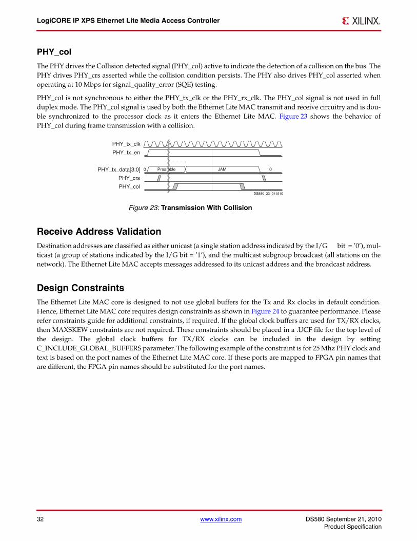
PHY_rx_er
The PHY drives the Receive Error signal (PHY_rx_er) synchronously to PHY_rx_clk. The PHY drives PHY_rx_erfor one or more PHY_rx_clk periods to indicate that an error (e.g., a coding error, or any error that the PHY is capa-ble of detecting) was detected somewhere in the frame presently being transferred from the PHY to the EthernetLite MAC.
PHY_rx_er should have no effect on the Ethernet Lite MAC while PHY_dv is de-asserted. This signal is transferredbetween the PHY_rx_clk and processor clock domains at the asynchronous RX bus FIFO interface.
The PHY will provide a minimum of 10 nS setup and hold time for this signal in reference to PHY_rx_clk. Figure 22shows the behavior of PHY_rx_er during frame reception with errors.
Table 15 shows the possible combinations for the receive signals.
PHY_crs
The PHY drives the Carrier Sense signal (PHY_crs) active to indicate that either the transmit or receive is non-idlewhen operating in half duplex mode. PHY_crs is de-asserted when both the transmit and receive are idle.
The PHY drives PHY_crs asserted throughout the duration of a collision condition. PHY_crs is not synchronous toeither the PHY_tx_clk or the PHY_rx_clk. The PHY_crs signal is not used in full duplex mode. The PHY_crs signalis used by both the Ethernet Lite MAC transmit and receive circuitry and is double synchronized to the processorclock as it enters the Ethernet Lite MAC.
X-Ref Target - Figure 22
Figure 22: Receive With Errors
Table 15: Possible Values for PHY_dv, PHY_rx_er, and PHY_rx_data[3:0]
PHY_dv PHY_rx_er PHY_rx_data[3:0] Indication
0 0 0000 through 1111 Normal inter-frame
0 1 0000 Normal inter-frame
0 1 0001 through 1101 Reserved
0 1 1110 False carrier indication
0 1 1111 Reserved
1 0 0000 through 1111 Normal data reception
1 1 0000 through 1111 Data reception with errors
PHY_rx_clk
PHY_dv
PHY_rx_er
PHY_rx_data[3:0] preambl e SFD D0 D1 xx D3 CRC
DS580_22_041910
LogiCORE IP XPS Ethernet Lite Media Access Controller
32 www.xilinx.com DS580 September 21, 2010Product Specification
PHY_col
The PHY drives the Collision detected signal (PHY_col) active to indicate the detection of a collision on the bus. ThePHY drives PHY_crs asserted while the collision condition persists. The PHY also drives PHY_col asserted whenoperating at 10 Mbps for signal_quality_error (SQE) testing.
PHY_col is not synchronous to either the PHY_tx_clk or the PHY_rx_clk. The PHY_col signal is not used in fullduplex mode. The PHY_col signal is used by both the Ethernet Lite MAC transmit and receive circuitry and is dou-ble synchronized to the processor clock as it enters the Ethernet Lite MAC. Figure 23 shows the behavior ofPHY_col during frame transmission with a collision.
Receive Address ValidationDestination addresses are classified as either unicast (a single station address indicated by the I/G bit = ’0’), mul-ticast (a group of stations indicated by the I/G bit = ’1’), and the multicast subgroup broadcast (all stations on thenetwork). The Ethernet Lite MAC accepts messages addressed to its unicast address and the broadcast address.
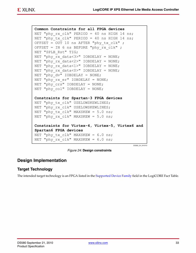
Design ConstraintsThe Ethernet Lite MAC core is designed to not use global buffers for the Tx and Rx clocks in default condition.Hence, Ethernet Lite MAC core requires design constraints as shown in Figure 24 to guarantee performance. Pleaserefer constraints guide for additional constraints, if required. If the global clock buffers are used for TX/RX clocks,then MAXSKEW constraints are not required. These constraints should be placed in a .UCF file for the top level ofthe design. The global clock buffers for TX/RX clocks can be included in the design by settingC_INCLUDE_GLOBAL_BUFFERS parameter. The following example of the constraint is for 25 Mhz PHY clock andtext is based on the port names of the Ethernet Lite MAC core. If these ports are mapped to FPGA pin names thatare different, the FPGA pin names should be substituted for the port names.
X-Ref Target - Figure 23
Figure 23: Transmission With Collision
PHY_tx_clk
PHY_tx_en
PHY_tx_data[3:0]
PHY_crs
PHY_col
0 Preamble JAM 0
DS580_23_041910
DS580 September 21, 2010 www.xilinx.com 33Product Specification
LogiCORE IP XPS Ethernet Lite Media Access Controller
Design Implementation
Target Technology
The intended target technology is an FPGA listed in the Supported Device Family field in the LogiCORE Fact Table.
X-Ref Target - Figure 24
Figure 24: Design constraints
Common Constraints for all FPGA devicesNET "phy_rx_clk" PERIOD = 40 ns HIGH 14 ns;NET "phy_tx_clk" PERIOD = 40 ns HIGH 14 ns;OFFSET = OUT 10 ns AFTER "phy_tx_clk" ;OFFSET = IN 6 ns BEFORE "phy_rx_clk" ;NET "SPLB_Rst" TIG;NET "phy_rx_data<3>" IOBDELAY = NONE;NET "phy_rx_data<2>" IOBDELAY = NONE;NET "phy_rx_data<1>" IOBDELAY = NONE;NET "phy_rx_data<0>" IOBDELAY = NONE;NET "phy_dv" IOBDELAY = NONE;NET "phy_rx_er" IOBDELAY = NONE;NET "phy_crs" IOBDELAY = NONE;NET "phy_col" IOBDELAY = NONE;
Constraints for Spartan-3 FPGA devicesNET "phy_tx_clk" USELOWSKEWLINES;NET "phy_rx_clk" USELOWSKEWLINES;NET "phy_tx_clk" MAXSKEW = 5.0 ns;NET "phy_rx_clk" MAXSKEW = 5.0 ns;
Constraints for Virtex-4, Virtex-5, Virtex6 and Spartan6 FPGA devicesNET "phy_tx_clk" MAXSKEW = 6.0 ns;NET "phy_rx_clk" MAXSKEW = 6.0 ns;
DS580_24_041910
LogiCORE IP XPS Ethernet Lite Media Access Controller
34 www.xilinx.com DS580 September 21, 2010Product Specification
Device Utilization and Performance Benchmarks
Core Performance
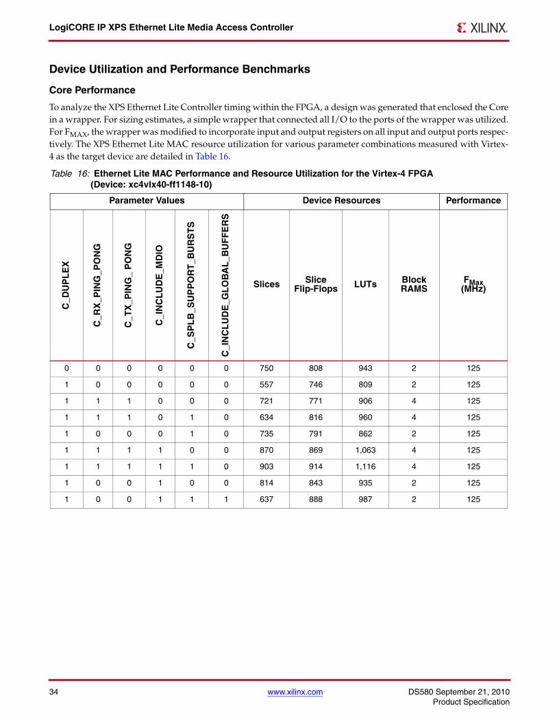
To analyze the XPS Ethernet Lite Controller timing within the FPGA, a design was generated that enclosed the Corein a wrapper. For sizing estimates, a simple wrapper that connected all I/O to the ports of the wrapper was utilized.For FMAX, the wrapper was modified to incorporate input and output registers on all input and output ports respec-tively. The XPS Ethernet Lite MAC resource utilization for various parameter combinations measured with Virtex-4 as the target device are detailed in Table 16.
Table 16: Ethernet Lite MAC Performance and Resource Utilization for the Virtex-4 FPGA (Device: xc4vlx40-ff1148-10)
Parameter Values Device Resources Performance
C_D
UP
LE
X
C_R
X_P
ING
_PO
NG
C_T
X_P
ING
_ P
ON
G
C_I
NC
LU
DE
_MD
IO
C_S
PL
B_S
UP
PO
RT
_BU
RS
TS
C_I
NC
LU
DE
_GL
OB
AL
_BU
FF
ER
S
Slices Slice Flip-Flops LUTs Block
RAMSFMax(MHz)
0 0 0 0 0 0 750 808 943 2 125
1 0 0 0 0 0 557 746 809 2 125
1 1 1 0 0 0 721 771 906 4 125
1 1 1 0 1 0 634 816 960 4 125
1 0 0 0 1 0 735 791 862 2 125
1 1 1 1 0 0 870 869 1,063 4 125
1 1 1 1 1 0 903 914 1,116 4 125
1 0 0 1 0 0 814 843 935 2 125
1 0 0 1 1 1 637 888 987 2 125
DS580 September 21, 2010 www.xilinx.com 35Product Specification
LogiCORE IP XPS Ethernet Lite Media Access Controller
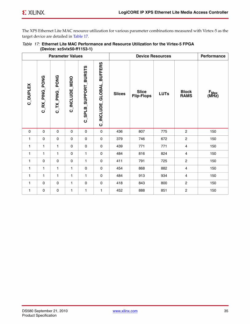
The XPS Ethernet Lite MAC resource utilization for various parameter combinations measured with Virtex-5 as thetarget device are detailed in Table 17.
Table 17: Ethernet Lite MAC Performance and Resource Utilization for the Virtex-5 FPGA (Device: xc5vlx50-ff1153-1)
Parameter Values Device Resources Performance
C_D
UP
LE
X
C_R
X_P
ING
_PO
NG
C_T
X_P
ING
_ P
ON
G
C_I
NC
LU
DE
_MD
IO
C_S
PL
B_S
UP
PO
RT
_BU
RS
TS
C_I
NC
LU
DE
_GL
OB
AL
_BU
FF
ER
S
Slices Slice Flip-Flops LUTs Block
RAMSFMax(MHz)
0 0 0 0 0 0 436 807 775 2 150
1 0 0 0 0 0 379 746 672 2 150
1 1 1 0 0 0 439 771 771 4 150
1 1 1 0 1 0 484 816 824 4 150
1 0 0 0 1 0 411 791 725 2 150
1 1 1 1 0 0 454 868 882 4 150
1 1 1 1 1 0 484 913 934 4 150
1 0 0 1 0 0 418 843 800 2 150
1 0 0 1 1 1 452 888 851 2 150
LogiCORE IP XPS Ethernet Lite Media Access Controller
36 www.xilinx.com DS580 September 21, 2010Product Specification
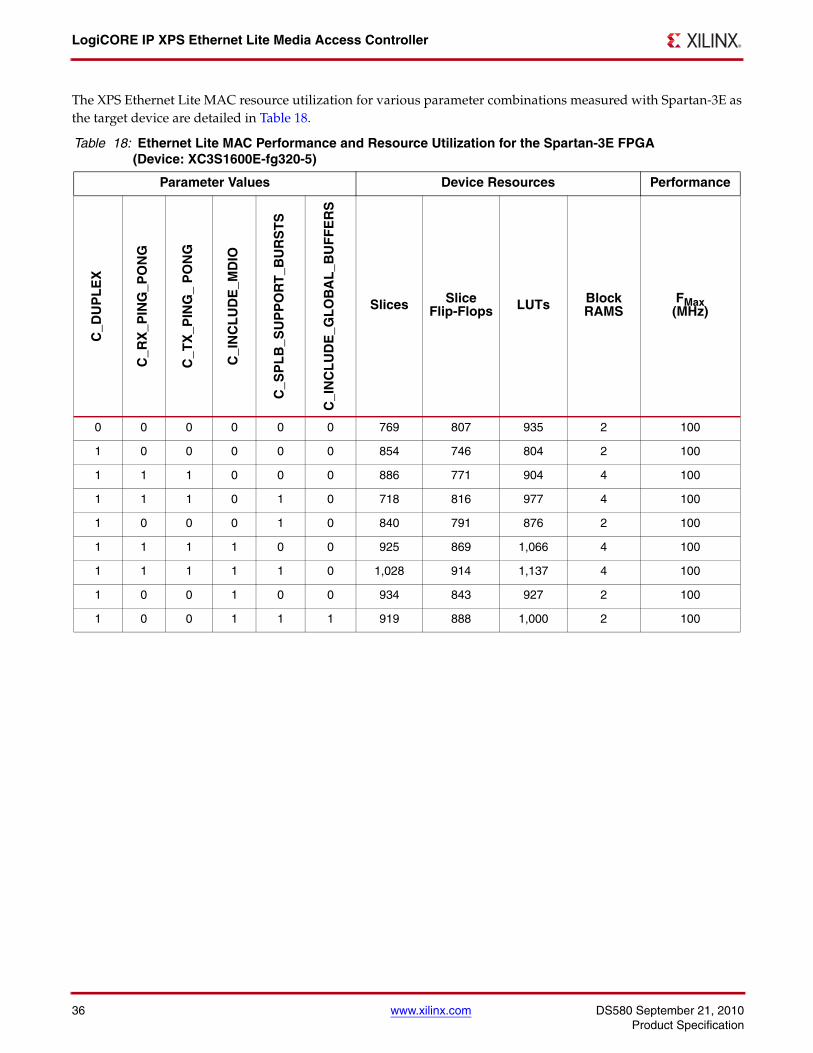
The XPS Ethernet Lite MAC resource utilization for various parameter combinations measured with Spartan-3E asthe target device are detailed in Table 18.
Table 18: Ethernet Lite MAC Performance and Resource Utilization for the Spartan-3E FPGA (Device: XC3S1600E-fg320-5)
Parameter Values Device Resources Performance
C_D
UP
LE
X
C_R
X_P
ING
_PO
NG
C_T
X_P
ING
_ P
ON
G
C_I
NC
LU
DE
_MD
IO
C_S
PL
B_S
UP
PO
RT
_BU
RS
TS
C_I
NC
LU
DE
_GL
OB
AL
_BU
FF
ER
S
Slices Slice Flip-Flops LUTs Block
RAMSFMax(MHz)
0 0 0 0 0 0 769 807 935 2 100
1 0 0 0 0 0 854 746 804 2 100
1 1 1 0 0 0 886 771 904 4 100
1 1 1 0 1 0 718 816 977 4 100
1 0 0 0 1 0 840 791 876 2 100
1 1 1 1 0 0 925 869 1,066 4 100
1 1 1 1 1 0 1,028 914 1,137 4 100
1 0 0 1 0 0 934 843 927 2 100
1 0 0 1 1 1 919 888 1,000 2 100
DS580 September 21, 2010 www.xilinx.com 37Product Specification
LogiCORE IP XPS Ethernet Lite Media Access Controller
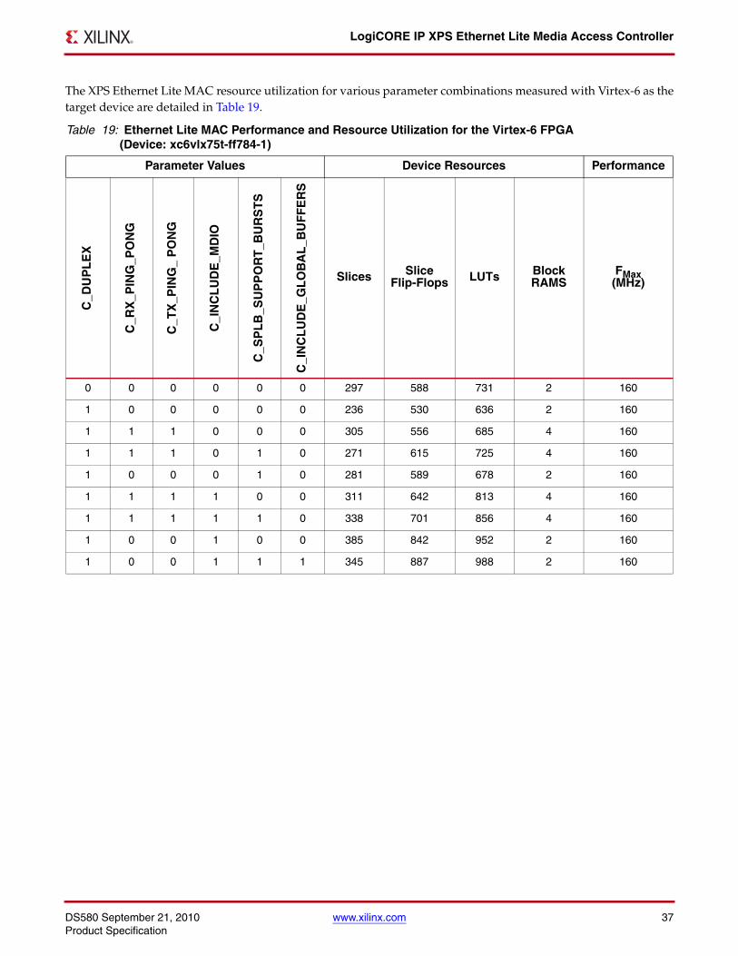
The XPS Ethernet Lite MAC resource utilization for various parameter combinations measured with Virtex-6 as thetarget device are detailed in Table 19.
Table 19: Ethernet Lite MAC Performance and Resource Utilization for the Virtex-6 FPGA (Device: xc6vlx75t-ff784-1)
Parameter Values Device Resources Performance
C_D
UP
LE
X
C_R
X_P
ING
_PO
NG
C_T
X_P
ING
_ P
ON
G
C_I
NC
LU
DE
_MD
IO
C_S
PL
B_S
UP
PO
RT
_BU
RS
TS
C_I
NC
LU
DE
_GL
OB
AL
_BU
FF
ER
S
Slices Slice Flip-Flops LUTs Block
RAMSFMax(MHz)
0 0 0 0 0 0 297 588 731 2 160
1 0 0 0 0 0 236 530 636 2 160
1 1 1 0 0 0 305 556 685 4 160
1 1 1 0 1 0 271 615 725 4 160
1 0 0 0 1 0 281 589 678 2 160
1 1 1 1 0 0 311 642 813 4 160
1 1 1 1 1 0 338 701 856 4 160
1 0 0 1 0 0 385 842 952 2 160
1 0 0 1 1 1 345 887 988 2 160
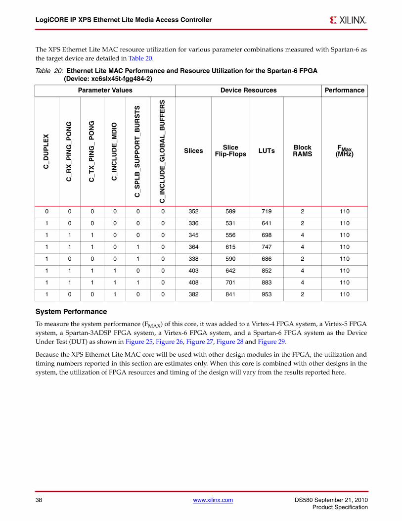
LogiCORE IP XPS Ethernet Lite Media Access Controller
38 www.xilinx.com DS580 September 21, 2010Product Specification
The XPS Ethernet Lite MAC resource utilization for various parameter combinations measured with Spartan-6 asthe target device are detailed in Table 20.
System Performance
To measure the system performance (FMAX) of this core, it was added to a Virtex-4 FPGA system, a Virtex-5 FPGAsystem, a Spartan-3ADSP FPGA system, a Virtex-6 FPGA system, and a Spartan-6 FPGA system as the DeviceUnder Test (DUT) as shown in Figure 25, Figure 26, Figure 27, Figure 28 and Figure 29.
Because the XPS Ethernet Lite MAC core will be used with other design modules in the FPGA, the utilization andtiming numbers reported in this section are estimates only. When this core is combined with other designs in thesystem, the utilization of FPGA resources and timing of the design will vary from the results reported here.
Table 20: Ethernet Lite MAC Performance and Resource Utilization for the Spartan-6 FPGA (Device: xc6slx45t-fgg484-2)
Parameter Values Device Resources Performance
C_D
UP
LE
X
C_R
X_P
ING
_PO
NG
C_T
X_P
ING
_ P
ON
G
C_I
NC
LU
DE
_MD
IO
C_S
PL
B_S
UP
PO
RT
_BU
RS
TS
C_I
NC
LU
DE
_GL
OB
AL
_BU
FF
ER
S
Slices Slice Flip-Flops LUTs Block
RAMSFMax(MHz)
0 0 0 0 0 0 352 589 719 2 110
1 0 0 0 0 0 336 531 641 2 110
1 1 1 0 0 0 345 556 698 4 110
1 1 1 0 1 0 364 615 747 4 110
1 0 0 0 1 0 338 590 686 2 110
1 1 1 1 0 0 403 642 852 4 110
1 1 1 1 1 0 408 701 883 4 110
1 0 0 1 0 0 382 841 953 2 110
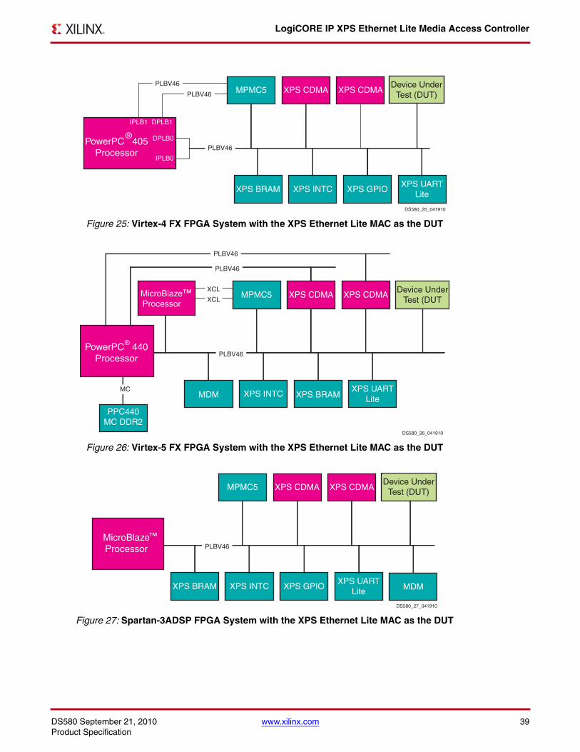
DS580 September 21, 2010 www.xilinx.com 39Product Specification
LogiCORE IP XPS Ethernet Lite Media Access Controller
X-Ref Target - Figure 25
Figure 25: Virtex-4 FX FPGA System with the XPS Ethernet Lite MAC as the DUT
X-Ref Target - Figure 26
Figure 26: Virtex-5 FX FPGA System with the XPS Ethernet Lite MAC as the DUT
X-Ref Target - Figure 27
Figure 27: Spartan-3ADSP FPGA System with the XPS Ethernet Lite MAC as the DUT
MPMC5 XPS CDMA
XPS UARTLite
XPS GPIOXPS INTCXPS BRAM
DPLB1IPLB1
DPLB0
IPLB0
XPS CDMAPLBV46
PLBV46
PLBV46
Device UnderTest (DUT)
PowerPC 405Processor
®
DS580_25_041910
MPMC5 XPS CDMADevice Under
Test (DUT
XPS UARTLite
XPS INTC
XPS CDMA
MDM
XCL
XCL
PLBV46
MicroBlaze
XPS BRAMMDM
PPC440MC DDR2
MC
PLBV46
PLBV46
PowerPC 440Processor
®
MicroBlazeProcessor
™
DS580_26_041910
MPMC5 XPS CDMADevice Under
Test (DUT)
XPS UARTLite
XPS GPIOXPS INTCXPS BRAM
XPS CDMA
MDM
PLBV46MicroBlazeProcessor
™
DS580_27_041910
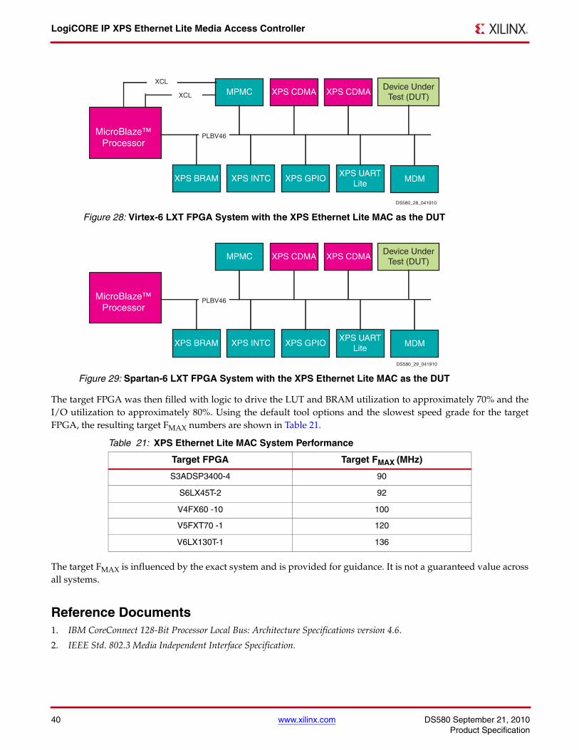
LogiCORE IP XPS Ethernet Lite Media Access Controller
40 www.xilinx.com DS580 September 21, 2010Product Specification
The target FPGA was then filled with logic to drive the LUT and BRAM utilization to approximately 70% and theI/O utilization to approximately 80%. Using the default tool options and the slowest speed grade for the targetFPGA, the resulting target FMAX numbers are shown in Table 21.
The target FMAX is influenced by the exact system and is provided for guidance. It is not a guaranteed value acrossall systems.
Reference Documents1. IBM CoreConnect 128-Bit Processor Local Bus: Architecture Specifications version 4.6.
2. IEEE Std. 802.3 Media Independent Interface Specification.
X-Ref Target - Figure 28
Figure 28: Virtex-6 LXT FPGA System with the XPS Ethernet Lite MAC as the DUT
X-Ref Target - Figure 29
Figure 29: Spartan-6 LXT FPGA System with the XPS Ethernet Lite MAC as the DUT
Table 21: XPS Ethernet Lite MAC System Performance
Target FPGA Target FMAX (MHz)
S3ADSP3400-4 90
S6LX45T-2 92
V4FX60 -10 100
V5FXT70 -1 120
V6LX130T-1 136
MicroBlaze™Processor
MPMC XPS CDMA
XPS UARTLite
XPS GPIOXPS INTCXPS BRAM
XPS CDMA
MDM
PLBV46
Device UnderTest (DUT)
XCL
XCL
DS580_28_041910
MicroBlaze™Processor
MPMC XPS CDMA
XPS UARTLite
XPS GPIOXPS INTCXPS BRAM
XPS CDMA
MDM
PLBV46
Device UnderTest (DUT)
DS580_29_041910
DS580 September 21, 2010 www.xilinx.com 41Product Specification
LogiCORE IP XPS Ethernet Lite Media Access Controller
Support Xilinx provides technical support for this LogiCORE product when used as described in the product documenta-tion. Xilinx cannot guarantee timing, functionality, or support of product if implemented in devices that are notdefined in the documentation, if customized beyond that allowed in the product documentation, or if changes aremade to any section of the design labeled DO NOT MODIFY.
Ordering InformationThis Xilinx LogiCORE IP module is provided at no additional cost with the Xilinx ISE Design Suite Embedded Edi-tion software under the terms of the Xilinx End User License. The core is generated using the Xilinx ISE EmbeddedEdition software (EDK)
For more information, please visit the XPS Ethernet Lite Media Access Controller product web page.
Information about this and other Xilinx LogiCORE IP modules is available at the Xilinx Intellectual Property page.For information on pricing and availability of other Xilinx LogiCORE modules and software, please contact yourlocal Xilinx sales representative.
Revision History
Date Version Revision
10/31/06 1.0 Initial Xilinx release.
9/26/07 1.1 Added Fmax Margin System Performance section.
11/27/07 1.2 Added SP-3A DSP support.
07/12/07 1.3 New version of DS created to make the core license free.
4/22/08 1.4 Added Automotive Spartan-3E, Automotive Spartan-3A, Automotive Spartan-3, and Automotive Spartan-3A DSP support.
7/22/08 1.5 Updated timing constraints section.
7/29/08 1.6 Added QPro Virtex-4 Hi-Rel and QPro Virtex-4 Rad Tolerant support.
11/11/08 1.7 Removed Virtex2P support.
12/16/08 1.8 Updated design constraint section.
4/28/09 1.9 Replaced references to supported device families and tool name(s) with hyperlink to PDF file; added MDIO interface description.
6/24/09 2.0 Updated for EDK_L 11.2; added supported device family and tools listing.
4/19/10 2.1 Updated for EDK_M 12.1; converted to current DS template.
9/21/10 2.2 Updated for 12.3 release; incorporated CR565438.
LogiCORE IP XPS Ethernet Lite Media Access Controller
42 www.xilinx.com DS580 September 21, 2010Product Specification
Notice of DisclaimerXilinx is providing this product documentation, hereinafter "Information," to you "AS IS" with no warranty of any kind, expressor implied. Xilinx makes no representation that the Information, or any particular implementation thereof, is free from anyclaims of infringement. You are responsible for obtaining any rights you may require for any implementation based on the Infor-mation. All specifications are subject to change without notice. XILINX EXPRESSLY DISCLAIMS ANY WARRANTY WHATSO-EVER WITH RESPECT TO THE ADEQUACY OF THE INFORMATION OR ANY IMPLEMENTATION BASED THEREON,INCLUDING BUT NOT LIMITED TO ANY WARRANTIES OR REPRESENTATIONS THAT THIS IMPLEMENTATION IS FREEFROM CLAIMS OF INFRINGEMENT AND ANY IMPLIED WARRANTIES OF MERCHANTABILITY OR FITNESS FOR APARTICULAR PURPOSE. Except as stated herein, none of the Information may be copied, reproduced, distributed, republished,downloaded, displayed, posted, or transmitted in any form or by any means including, but not limited to, electronic, mechani-cal, photocopying, recording, or otherwise, without the prior written consent of Xilinx.