xii. literature cited - link.springer.com978-94-009-5065-8/1.pdf · xii. literature cited ... the...
TRANSCRIPT
XII. Literature cited
Albersheim, P. (1975) The walls of growing plant cells. Sci. Amer. 2324: 80-95. AJexandrov, W.G. and L.I. Djaparidz (1927) Ober das Entholzen und Verholzen der Zellhaut.
Planta, 4: 467-475. Anderson, D.B. and T. Kerr (1938) Growth and structure of cotton fibre. Ind. & Eng. Chem. 301:
48-54. Balashov, V., R.D. Preston, G.W. Ripley and L.c. Spark (1957) Structure and mechanical properties
of vegetable fibres. 1. The influence of strain on the orientation of cellulose microfibrils in sisal leaf fibre. R. Soc. (Land.), Proc. Ser. B, 156: 460-468.
Balch, R.E. (1952) Studies of the balsam woolly aphid, Adelges piceae (Ratz) (Homoptera: Phylloxeridae) and its effects on balsam fir, Abies balsamea (L) Mill. Can. Dep. Agric. Publ. No. 867.
Bamber, R.K. (1979) The origin of growth stresses. Forpride Digest 8: 75-79. Bauer, W.D., K.W. Talmadge, K. Keegstra and P. Albersheim (1973) The structure of plant cell
walls. II. The hemicellulose of the walls of suspension-cultured sycamore cells. Plant Physiol. 51: 174-187.
Belford, D.S. and R.D. Preston (1961) The structure and growth of root hairs. J. Exp. Bot. 12: 157-168.
Bohmer, H. (1958) Untersuchungen tiber das Wachs tum und den Feinbau der Zellwande in der Avena Koleoptile. Planta 50: 461-497.
Bonner, J. (1935) Zum Mechanismus der Zellstreckung auf Grund der Michellarlehre. Jb. Wiss. Bot. 82: 377-410.
Bouligand, Y. (1972) Twisted fibrous arrangements in biological materials and cholesteric mesophases. Tissue & Cell 4: 189-217.
Boyd, J.D. (1950a) Tree growth stresses. 1. Growth stress evaluation. Aust. J. Sci. Res. Ser. B 3: 270-293
Boyd, J.D. (1950b) Tree growth stresses. II. The development of shakes and other visual failures in timber. Aust. J. App!. Sci. 1: 296-312.
Boyd, J.D. (1950c) Tree growth stresses. III. The origin of growth stresses. Aust. 1. Sci. Res. Ser. B 3: 294-309.
Boyd, J.D. (1972) Tree growth stresses. V. Evidence of an origin in differentiation and lignification. Wood Sci. Techno!. 6: 251-262.
Boyd, J.D. (1973a) Compression wood force generation and functional mechanics. N.Z. J. For. Sci. 3: 240-258.
Boyd, J.D. (1973b) Helical fissures in compression wood cells. Causative factors and mechanics of development. Wood Sci. Technol. 7: 92-111.
Boyd, J.D. (1974a) Anisotropic shrinkagc of wood. Idcntification of the dominant determinants. J. Japan Wood Res. Soc. 20: 473-482.

172
Boyd, J.D. (1974b) Relating lignification to microfibril angle diffcrences bctween tangential and radial faces of all wall layers in wood cells. Drevarsky Vyskum 19: 41-54.
Boyd, J.D. (1977a) Relationship between fibre morphology and shrinkage of wood. Wood Sci. Technol. 11: 3-22.
Boyd, J.D. (1977b) Interpretation of X-ray diffractograms of wood for assessments of microfibril angles in fibre cell walls. Wood Sci. Technol. 11: 93-114.
Boyd, J.D. (1977c) Basic cause of differentiation of tension wood and compression wood. Aust. For. Res. 7: 121-143.
Boyd, J.D. (1978) Significance of laricinan in compression wood tracheids. Wood Sci. Technol. 12: 25-35.
Boyd, J.D. (1980) Relationships between fibre morphology, growth strains and wood properties. Aust. For. Res. 10: 337-360.
Boyd, J.D. (1982) An anatomical explanation for visco-elastic and mechano-sorptive creep in wood, and effects of loading rate on strength. In: P. Baas (ed.) New Perspectives in Wood Anatomy. Martinus NijhoffiDr. W. Junk, The Hague, The Netherlands, pp. 171-222.
Boyd. J.D. and R.C. Foster (1974) Tracheid anatomy changes are responses to changing structural requirements of the tree. Wood Sci. Technol. 8: 91-105.
Boyd, J.D. and R.C. Foster (1975) Microfibrils in primary and secondary wall growth develop trellis configurations. Can. J. Bot. 53: 2687-2701.
Boyd, J.D. and K.B. Schuster (1972) Tree growth stresses - Part IV: Visco-elastic strain recovery. Wood Sci. Technol. 6: 95-120.
Brown, C.L. (1964) The influence of external pressure on the differentiation of cells and tissues cultured in vitro. In: M.H. Zimmermann (ed.) The Formation a/Wood in Forest Trees. Academic Press. New York & London, pp. 389-404.
Brown, c.L. and K. Sax (1962) Influence of pressure on the differentiation of secondary tissues. Am. 1. Bot. 49: 683-691.
Burke, D., P. Kaufmann. M. McNeil and P. Albersheim (1974) The structure of plant cell walls. VI. A survey of the walls of suspension-cultured monocots. Plant Physiol. 54: 109-115.
Burstriim, H. (1942) Die osmolischen Verhaltnisse wahrend des Strechungswachstums der Wurzel. Ann. Agr. Call. Sw. 10: 1-30.
Castle, E.S. (1937)Membrane tension and orientation of structure in the plant cell wall. 1. Cell. Compo Physiol. 10: 113-121.
Chafe, S.c. (1970) The fine structure of collenchyma cell wall. Planta (Berl.) 90: 12-21. Chafe, S.C. (1974a) Cell wall thickenings in the ray parenchyma of yellow cypress. I.A. W.A. Bull,
19742: 3-10. Chafe, S.c. (1974b) Wall structure in xylem of parenchyma of Cryptomeria. Protoplasma 81: 63-76. Chafe, S.c. and G. Chauret (1974) Cell wall structure in xylem parenchyma of trembling aspen.
Protoplasma 80: 129-147. Chafe, S.C. and M.E. Doohan (1972) Observations on the ultrastructure of the thickened sieve cell
wall in Pinus strobus L. Protoplasma 75: 67-78. Chafe, S.C. and A.B. Wardrop (1972) Fine structural observations on the epidermis. I. The epidermal
cell wall. Planta (Berl.) 107: 269-278. Cleland, R. (1959) Effect of osmotic concentration on auxin action and on irreversible and reversible
expansion of Avena coleoptile. Physiol. Plantarum 12: 809-825. Cleland, R. (1967a) A dual role of turgor pressure in auxin-induced cell elongation in Avena
coleoptiles. Planta (Berl.) 77: 182-190. Cleland, R. (1967b) Extensibility of isolated cell walls: measurement of changes during cell elonga
tion. Planta (Berl.) 74: 197-209. Cleland, R. (1968a) Hydroxyproline formation and its relation to auxin-induced cell elongation in the
Avena coleoptile. Plant Physiol. 43: 1625-1630.
173
Cleland, R. (1968b) Auxin and wall extensibility: reversibility of auxin-induced wall-loosening process. Science 160: 192-194.
Cleland, R. (1971) The mechanical behaviour of isolated Avena coleoptile walls subjected to constant stress: properties and relation to cell elongation. Plant Physiol. 47: 805-81l.
Cleland, R. and P.M. Haughton (1971) The effect of auxin on stress relaxation in isolated Avena coleoptiles. Plant Physiol. 47: 812-815.
Clowes, F.A.L. and B.E. Juniper (1968) Plant Cells. Blackwell Scientific Publications. Oxford, UK. C6te, W.A. and A.C. Day (1965) Anatomy and ultrastructure ofreaction wood. In: W.A. C6te (ed.)
Cellular Ultrastructure of Woody Plants. Syracuse University Press, pp. 391-418. C6te. W.A., A.C. Day and T.E. Timell (1969) A contribution to ultrastructure of tension wood
fibres. Wood Sci. Technol. 3: 257-27l. Cox, G. and B. Juniper (1973) Electron microscopy of cellulose in entire tissue. l. Microscopy 97: 343-
355. Cronshaw, J. and R.D. Preston (1958) A re-examination of the fine structure of the walls of vesicles of
the green alga Valonia. R. Soc. (Lond.), Proc. Ser. B 148: 137-148. Dunning, C.E. (1969) The structure of longleaf-pine latewood.1. Cell-wall morphology and the effect
of alkaline extraction. Tappi 52: 1326-1335. Emons, A.M.C and A.M.C. Wolters-Arts (1983) Cortical microtubules and microfibril deposition in
the cell wall of root hairs of Equisetum hyemale. Protoplasma 117: 68--81. Esau, K. (1965) Plant Anatomy (2nd edn.) John Wiley & Sons Inc., New York. Eshbach, O.D. (1952) Handbook of Engineering Fundamentals (2nd edn.) John Wiley & Sons Inc.,
New York; Chapman and Hall Limited. London. Flint, E.A. (1950) The sructure and development of the cotton fibre. Bioi. Revs. Cambridge Phil. Soc.
25: 414-434. Foster, R.C. (1967) Fine structure of tyloses in three species of Myrtaceae. Aust. 1. Bot. 15: 25-34. Frei, E. and R.D. Preston (1961a) Cell wall organization and wall growth in the filamentous green
algae Cladophora and Chaetoll1orpha. I. The basic structure and its formation. R. Soc. (Lond.), Proc. Ser. B 154: 70--94.
Frei, E. and R.D. Preston (1961b) Cell wall organization and wall growth in the filamentous green algae Cladophora and Chaetoll1orpha. II. Spiral structure and spiral growth. R. Soc. (Lond.), Proc. Ser. B 155: 55-77.
Frei, E. and R.D. Preston (1964a) Non-cellulosic structural polysaccharides in algal cell walls. I. Xylan in siphoneous green algae. R. Soc. (Lond.), Proc. Ser. B 160: 293-313.
Frei, E. and R.D. Preston (1964b) Non-cellulosic structural polysaccharides in algal cell walls. II. Association ofxylan and mannan in Porphyra ull1bilicalis. R. Soc. (Lond.), Proc. Ser. B 160: 314-327.
Frey, A. (1926) Submikroskopische Struktur der Zellmembranen. Polarisations-optische Studie zum Nachweis der Richtigkeit der Micellartheorie. lb. Wiss. Bot. 56, Pt. II: 195-223.
Frey-Wyssling, A. (1976) The Plant Cell Wall. Gebriider Borntraeger, Berlin, Stuttgart. Fukazawa. K. and H. Imagawa (1981) Quantitative analysis of lignin using UV microscopic image
analyser. Variation within one growth increment. Wood Sci. Technol. 15: 45-55. Gertel, E.T. and P.B. Green (1977) Growth pattern and wall microfibril arrangement; experiments
with Nitella. Plant Physiol. 60: 247-254. Green, P.B. (1954) The spiral growth pattern of the cell wall in Nitella axillaris. Am. l. Bot. 41: 403-
409. Green, P.B. (1958) Structural characteristics of developing Nitella internodal cell walls. l. Biophysic.
Biochell1. Cytol. 4: 505-516. Green, P.B. (1959) Wall structure and helical growth in Nitella. Biochim. Biophys. Acta 36: 536-538. Green, P.B. (1960a) Multinet growth in the cell wall of Nitella. 1. Biophysic. Biochell1. Cytol. 7: 289-
295.
174
Green, P.B. (1960b) Wall structure and lateral formation in the alga Bryopsis. Am. 1. Bot. 47: 476--481.
Green, P.B. (1962) Mechanism for plant cellular morphogenesis. Science 138: 1404--1405. Green, P.B. (1963) Cell walls and the geometry of plant growth. In: Meristems and Differentiation.
Brookhaven Symp. BioI. No. 16, pp. 203-215. Green, P.B. (1969) Cell morphogenesis. Ann. Rev. Plant Physiol. 20: 365-394. Green, P.B. and G.B. Chapman (1955) On the development and structure of the cell wall in Nitella.
Am. 1. Bot. 42: 685-693. Green, P.B. and J.C.W. Chen (1960) Concerning the role of wall stresses in the elongation of the
Ni/ella cell. Z. Wiss. Mikroskopie 64: 482-488. Green, P.B., R.O. Erickson and J. Buggy (1971) Metabolic and physical control of cell elongation
rate: in vivo studies in Nitella. Plant Physiol. 47: 423-430. Grozdits, G.A. and G. Ifju (1969) Development of tensile strength and related properties in differen
tiating coniferous xylem. Wood Sci. I: 137-147. Harada, H. (1965) Ultrastructure and organization of gymnosperm cell walls. In: W.A. Cote (ed.)
Cellular Ultrastructure of Woody Plants. Syracuse Univ. Press, Syracuse, pp. 215-233. Heyn, A.N.J. (1931) Der Mechanismus der Zellstreckung. Recl. Trav. Bot. Neerl. 28: 113-224. Hoffman, L.R. and C.S. Hofmann (1975) Zoospore formation in Cylindrocapsa. Can. 1. Bot. 33: 439-
451. Hoster, H.R. (1970) Gelatinose Tracheiden im sekundaren Xylem von Larix leptoleptis (S, et Z.)
Gord. Holzforschung 20: 80-90. Houwink, A.L. and P .A. Roelofsen (1954) Fibrillar architecture of growing plant cell walls. Acta Bot.
Neer!. 3: 385-395. Hughes, ] .F. (1965) Tension wood: a review of the literature. For Abstr. 26: 1-16. Iterson, G. van, Jr. (1937) A few observations on the hairs of the stamens of Tradescantia virginica.
Protoplasma 27: 190-211. Itoh, T. (1975a) Fine structure of the plasmalemma surface of poplar parenchyma cells observed by
the freeze etching technique. Bot. Mag. Tokyo 88: 131-143. Itoh, T. (1975b) Cell wall organization of cortical parenchyma of angiosperms observed by the freeze
etching technique. Bot. Mag. Tokyo 88: 145-156. Itoh, T. (1979) Studies on the structure and growth of primary walls of woody plants. Wood Res. 65:
54--110. Jacobs, M.R. (1938) The fibre tension of woody stems, with special reference to the genus Eucalyptus.
Commonw. For. Bur. Aust. Bull. No. 22. Jacobs, M.R. (1945) The growth stresses of woody stems. Commonw. For. Bur. Aust. Bull. No. 24. ] acquiot, C. and Y. Trenard (1974) Note sur la Presence de Tracheides a Parois Gelatineuses dans des
Bois Resineau. Holzforschung 28: 73-76. Jane, F.W. (1970) The Structure of Wood. A. and C. Black, London. Kadita, S., K. Kobayashi and T. Yamamoto (1955) Structure of tyloses (trans.). Pap. 64th Mtg. lap.
For. Soc. Keith, c.T. (1971) The anatomy of compression failure in relation to creep-inducing stresses. Wood
Sci. 4: 71-82. Kellogg, R.M. and G.L. Steucek (1977) Motion-induced growth effects in Douglas fir. Can. 1. For.
Res. 7: 94--99. Kennedy, R.W. and J.L. Farrar (1965) Tracheid development in tilted seedlings. In: W.A. Cote (ed.)
Cellular Ultrastructure of Woody Plants. Syracuse Univ. Press, pp. 419-453. Kerr, A.J. (1974) Physico-chemical mechanisms of delignification. Ph.D. Thesis, McGill University. Kishi, K., H. Harada and H. Saiki (1977) Layered structure of the secondary wall in vessels of
hardwoods by polarizing microscopy. Kyoto Univ. Forests, Bull. No. 49: 122-126. Kishi, K., H. Harada and H. Saiki (1979) An electron microscopic study ofthe layered structure of the
secondary wall in vessels. I. lap. Wood Res. Soc. 25: 521-527.
175
Kollmann. F.F.P. and W.A. Cote (1968) Principles o/Wood Science and Technology, 1. Solid Wood. Springer Verlag, Berlin, Heidelberg.
Kopp, M. (1948) Uber das Sauerstoffbediirfnis wachsender Pflanzenzellen. Ber. Schweiz. Bot. Ges. 58: 283-318.
Koran, Z., and W.A. Cote (1965) Ultrastructure of tyloses. In: W.A. Cote (ed.) Cellular Ultrastructure o/Woody Plants .. Syracuse Univ. Press, pp. 319-333.
Krabbe, G. (1882) Uber die Beziehungen der Rindenspannung zur Bildung der Jahrringe und zur Ablenkung der Markstrahlen. Sitzungsberichte der koniglich preussischen Akademie der Wissenschaften zu Berlin (now Sitzber. deut. Akad. Wiss. Berlin). Mathematische und naturwissenscha/tliche Mitteilungen 1882: 617-667.
Lamport, D.T.A. (1965) The protein component of primary cell walls. In: R.D. Preston (ed.) Advances in Botanical Research. Academic Press, London and New York, pp. 151-218.
Lockhart, J .A. (1967) Physical nature of irreversible deformation of plant cells. Plant Physiol. 42: 1545-1552.
Mark, R.E. and P.P. Gillis (1973) The relationship between fibre modulus and S2 angle. Tappi 56: 164--167.
Metzger, J.D. and G.L. Steucek (1974) Response of barley (Hordeum vulgare) seedlings to mechanical stress. Proc. Pa. Acad. Sci. 48: 114--116.
Meylan, B.A. and B. V. Butterfield (1978) Helical orientation of micro-fibrils in tracheids, fibres and vessels. Wood Sci. Technol. 12: 219-222.
Miyakawa, M., M. Fujita, H. Saiki and H. Harada (1973) The cell wall structure of the secondary phloem elements in Cryptomeria japonica, D. Don. Bull. Kyoto Univ. Forests, No. 45: 181-191.
Mosse, B. (1970) Honey-coloured, sessile Endogone spores. III Wall structure. Arch. Mikrobiol. 74: 146-159.
Nanko, H., H. Saiki and H. Harada (1977) Development and structure of phloem fibres in the secondary phloem of Populus euramericana. J. Japan Wood Res. Soc. 23: 267-272.
Nanko, H., H. Saiki and H. Harada (1978) Cell wall structure of the sclereids in secondary phloem of Populus euramericana. J. Japan Wood Res. Soc. 24: 362-368.
Nanko, H., H. Saiki and H. Harada (1979) Development and structure of the fiber-sci ere ids in the secondary phloem of Prunus jamasakura. 1. Japan Wood Res. Soc. 25: 245-250.
Nanko, H., H. Saiki and H. Harada (1982) Structural modification of secondary phloem fibres in the reaction phloem of Populus euramericana. J. Japan Wood Res. Soc. 28: 202-207.
Neel, P.L. and R.W. Harris (1971) Motion-induced inhibition of elongation and induction of dormancy in Liquidambar. Science 173: 58--59.
Necesany, V. (1955) Electronenmikroskopische Untersuchungen der Thyllen und der Kernstoff der Rotbuche Fagus sylvatica L. Bot. Tidsskr. 52: 48-55.
Neville, A.C., D.C. Gubb and R.M. Crawford (1976) A new model for cellulose architecture in some plant cell walls. Protoplasma 90: 307-317.
Neville, A.C. and B.M. Luke (1971) A biological system producing a self-assembling cholesteric protein liquid crystal. rCell Sci. 8: 93-109.
Nilsson, T. (1981) Helical orientation of the microfibrils in fibres of Mastixiodendron pachyclados (K. Schum.) MeJch. fA WA Bull. n.s. 2: 186.
Norberg, H. and H. Meier (1966) Physical and chemical properties of the gelatinous layer in tension wood fibres of aspen (Populus tremula L.). Holz/orschung 20: 174--178.
O'Brien, T.P. and K.V. Thimann (1966) Intracellular fibres in oat coleoptile cells and their possible significance in cytoplasmic streaming. Proc. Nat. Acad. Sci. 56: 888-894.
O'Kelley, J.e. (1953) The use of C14 in locating growth regions in the cell walls of elongating cotton fibres. Plant Physiol. 28: 281-286.
Okumura, S., H. Harada and H. Saiki (1974) The variation in the cell wall thickness along the length of a conifer tracheid. Bull. Kyoto Univ. Forests, No. 46: 162-168.
Okumura, S., H. Harada and H. Saiki (1977) Thickness variation of the G-layer along a mature and a differentiating tension wood fibre in Populus euramericana. Wood Sci. Technol. 11: 23-32.
176
Pagano, N.J., J.e. Halpin and J.M. Whitney (1968) Tension buckling of anisotropic cylinders. 1. Composite Materials 2: 154-167.
Page, D.H., F. El-Hosseiny and K. Winkler (1971) Behavior of single wood fibres under axial tensile strain. Nature 229: 252-253.
Panshin, A.V. and e. de Zeeuw (1970) Textbook of Wood Technology, Vol. 1. McGraw-Hill, New York.
Parameswaran, N. (1975) Zur Wandstruktur von Sklereiden in einigen Baumrinden. Protoplasma 85: 305-314.
Parameswaran, N. and W. Liese (1975) On the polylaminate structure of parenchyma wall in Phyllostachys edulis Riv. IAWA Bull. 1975: 57-58.
Parameswaran, N. and W. Liese (1980) Ultrastructual aspects of bamboo cells. Cellulose Chem. Technol. 14: 587-609.
Parameswaran, N. and W. Liese (1981) Occurrence and structure of polylamellate walls in some lignified cells. In: D.G. Robinson and H. Quader (eds.) Cell Walls '81, Proc. of the second cell wall meeting. Gottingen, Apr. 8-11, 1981, pp. 171-188.
Preston, R.D. (1938) The structure of the walls of parenchyma in Avena coleoptiles. R. Soc. (Lond.) Proc. Ser. B 125: 372-386.
Preston, R.D. (1941) The fine structure of phloem fibres; II. Untreated and swollen jute. Proc. R. Soc. (London), Ser. B 130: 103-112.
Preston, R.D. (1964) Structural and mechanical aspects in plant cell walls with particular reference to synthesis and growth. In: M.E. Zimmermann (ed.) Formation of Wood in Forest Trees. New York, Academic Press, pp. 169-183.
Preston, R.D. (1974) The Physical Biology of Plant Cell Walls. Chapman and Hall, London. Preston, R.D. (1982) The case for multinet growth in growing walls of plants. Planta 155: 356-363. Preston, R.D. and M. Middlebrook (1949) The fine structure of sisal fibres. 1. Text. Inst. 40: TI15-
TI22. Probine, M.e. (1963) Cell growth and the structure and mechanical properties of the wall in
internodal cells of Nitella opaca. III. Spiral growth and cell wall structure. 1. Expt. Bot. 14: 101-113. Probine, M.e. and M.F. Barber (1966) The structure and plastic properties of the cell wall of Nitella in
relation to extension growth. Aust. 1. Bioi. Sci. 19: 439-457. Probine, M.e. and R.D. Preston (1958) Protoplasmic streaming and wall structure in Nitella. Nature
182: 1657-1658. Probine, M.C. and R.D. Preston (1961) Cell growth and the structure and mechanical properties of
the wall in Nitella opaca. I. Wall structure and growth. 1. Exp. Bot. 12: 261-284. Probine, M.e. and R.D. Preston (1962) Cell growth and the structure and mechanical properties of
the wall in internodal cells of Nitella opaca. II. Mechanical properties of the walls. 1. Expt. Bot. 13: 111-127.
Ray, P.M. (1967) Radioautographic study of cell wall deposition in growing plant cells. 1. Cell Bioi. 35: 659-674.
Ray, P.M. a1id A.W. Ruesink (1962) Kinetic experiments on the nature of the growth mechanism in oat coleoptile cells. Develop. Bioi. 4: 377-397.
Roark, R.J. (1943) Formulas for Stress and Strain (2nd edn.) McGraw-Hill Book Co. Inc., New York, London.
Roelofsen, P.A. (1959) The Plant Cell Wall. Gebriider Borntraeger, Berlin - Nikolassee. Roelofsen, P.A. (1965) Ultrastructure of the wall in growing cells and in relation to the direction of
growth. In: R.D. Preston (ed.) Advances in Botanical Research. Academic Press, London & New York, pp. 64-149.
Roelofsen, P .A. and A.L. Houwink (1953) Architecture and growth of the primary cell wall in some plant hairs and in the Phycomyces sporangiophore. Acta Bot. Neerl. 2: 218-225.
Roland, J.e. (1964) Infrastructure des membranes du collenchyme. C.R. Acad. Sci. (Paris) 259: 4331-4334.
177
Roland, J.e. (1965) Edification et infrastructure de la membrane collenchyma-teuse. Son remaniemont lors de la sclerification. C.R. Acad. Sci. (Paris) 260: 950-953.
Roland, J.e. (1966) Organization de la membrane paraplasmique du collenchyme. I. Microscopie 5: 323-348.
Roland, J.e. (1973) The relationship between the plasmalemma and the plant cell wall. Inl. Rev. Cytol. 36: 45-92.
Roland, J.C. (1981) Comparison of arced patterns in growing and non-growing polylamellate cell walls of higher plants. In: D.G. Robinson and H. Quader (eds.) Cell Walls '81. Proc. of the second cell wall meeting. G6ttingen, April 8-11, 1981, pp. 162-169.
Roland, J .e., B. Vian and D. Reis (1975) Observations with cytochemistry and ultracryotomy of the fine structure of the expanding walls in actively elongating plant cells. I. Cell Sci. 19: 239-259.
Roland, J.e., B. Vi an and D. Reis (1977) Further observations on cell wall morphogenesis and polysaccharide arrangement during plant growth. Protoplasma 91: 125-141.
Roland, J.e. and B. Vian (1979) The wall of the growing plant cell: its three-dimensional organization. Int. Rev. Cytol. 61: 129-166.
Sachsse, H. (1965) Untersuchiingen der Eigenschaften und Funktionsweise des Zugholzes der Laubbiiume. Forstliche Facultiit, Georg-August-Univ., G6ttingen. Schriftenreihe No. 35.
Saiki, H. (1970) Influence of wood structure on radial variations in some physical properties within an annual ring of conifers. Coil. Agric. Kyoto Univ. Mem. No. 96: 47-73.
Saka, S. and R.J. Thomas (1982) A study oflignification ofloblolly pine tracheids by the SEM-EDXA technique. Wood Sci. Technol. 16: 167-179.
Sargent, e. (1978) Differentiation of the crossed-fibrillar outer epidermal wall during extension growth in Hordium vulgare L. Protoplasm a 95: 309-320.
Sawhney, V.K. and L.M. Srivastava (1975) Wall fibrils and microtubules in normal and gibberillicacid-induced growth of lettuce hypocotyl cells. Can. I. Bot. 53: 824--835.
Scurfield, G. and D.E. Bland (1963) Anatomy and chemistry of 'rubbery' wood in apple var. Lord Lambourne. I. Hortic. Sci. 38: 297-306.
Setterfield, G. and S.T. Bayley (1958) Arrangement of cellulose microfibrils in walls of elongating parenchyma cells. Biophysic. Biochem. Cytol. 4: 377-382.
Setterfield, G. and S.T. Bayley (1959) Deposition of cell walls in oat coleoptiles. Can. I. Bot. 37: 861-870.
Setterfield, G. and S.T. Bayley (1961) Structure and physiology of cell walls. Ann. Rev. Plant Physiol. 12: 35-62.
Steucek, G.L. and L.K. Gordon (1975) Response of wheat (Triticum aestovibum) seedlings to mechanical stress. Bot. Gaz. 136: 17-19.
Steward, F.C. and K. Miihlethaler (1953) The structure and development of the cell-wall in the Valoniaceae as revealed by the electron microscope. Ann. Bot., N.S. 17: 295-316.
Stone, J.E., A.M. Scallan and P.A.V. Ahlgren (1971) The ultrastructural distribution of lignin in tracheid cell walls. Tappi 54: 1527-1530.
Talmadge, K.W., K. Keegstra, W.D. Bauer and P. Albersheim (1973) The structure of plant cell walls. 1. The macromolecular components of the walls of suspension-cultured sycamore cells, with a detailed analysis of the pectic polysaccharides. Plant Physiol. 51: 158-173.
Tang, R.e. (1973) The microfibrillar orientation in cell wall layers of Virginia pine tracheids. Wood Sci. 5: 181-186.
Thompson, D'Arcy. (1942) On growth and form. 2nd ed. Cambridge University Press. Timoshenko, S. (1940) Strength of materials. Lancaster Press, Inc., Lancaster, Pa. USA. Tripp, V.W., A.T. Moore, and M.L. Rollins. (1954) A microscopical study of the effects of some
typical chemical environments on the primary wall of the cotton fibre. Textile Res. I. 24: 956-970. Valent, B.S. and P. Albersheim (1974) The structure of plant cell walls. V. On the binding of
xyloglucan to cellulose fibers. Plant Physiol. 54: 105-108. Veen, B. W. (1971) Dr. thesis, Groningen. Not seen; extract by A. Frey-Wyssling (1976) In: The Plant
Cell Wall. Gebriider Borntraeger, Berlin/Stuttgart.
178
Venning, F.D. (1949) Stimulation by wind motion on collenchyma formation in celery petioles. Bot. Gaz. 110: 511-514.
Walker, W.S. (1957) The effect of mechanical stimulation on the collenchyma of Apium graveolens L. Iowa Acad. Sci. 64: 177-186.
Walker, W.S. (1960) The effects of mechanical stimulation and etoliation on the collenchyma of Datura stramonium. Am. 1. Bot. 47: 717-724.
Wardrop, A.B. (1955) The mechanism of surface growth in parenchyma of Avena coleoptiles. Aust. 1. Bot. 3: 137-156.
Wardrop, A.B. (1956) The nature of surface growth in plant cells. Aust. 1. Bot. 4: 193-199. Wardrop, A.B. (1957) The organization and properties of the outer layer of the secondary wall of
conifer tracheids. Holzforschung 11: 102-110. Wardrop, A.B. (1962) Cell wall organization in higher plants. Bot. Rev. 28: 241-285. Wardrop, A.B. (1964) The structure and formation of the cell wall in xylem. In: M.H. Zimmermann
(ed.) The Formation of Wood in Forest Trees. Academic Press Inc., New York, pp. 87-135. Wardrop, A.B. (1969) The structure of the cell wall in the lignified collenchyma of Eryngium sp.
(Umbelliferae). AtLSt. 1. Bot. 17: 229-240. Wardrop, A.B. (1971) Lignins: occurrence and formation in plants. In: K.V. Sarkanen and C.H.
Ludwig (eds.) Lignins. John Wiley & Sons Inc., pp. 19-41. Wardrop, A.B. and F. W. Addo-Ashong (1963) The anatomy and fine structure of wood in relation to
mechanical failure. In: Tewksbury Symposium on Fracture, 1963 pp. 169-200. Wardrop, A.B. and J. Cronshaw (1958) Changes in cell wall organization resulting from surface
growth in parenchyma of oat coleoptiles. Aust. 1. Bot. 6: 89-95. Wardrop, A.B. and H.E. Dadswell (1953) Development of the conifer tracheid. Holzforschung 7
(2/3): 33-39. Wardrop, A.B. and H.E. Dadswell (1955) The nature of reaction wood. IV. Variations in cell wall
organization in tension wood fibres. Aust. 1. Bot. 3: 177-189. Wardrop, A.B. and H. Harada (1965) The formation and structure of the cell wall in fibres and
tracheids. 1. Exp. Bot. 16: 356-371. Wardrop, A.B., M. Wolters-Arts and M.M.A. Sassen (1979) Changes in microfibril orientation in
walls of elongating plant cells. Acta Bot. Nee!. 28: 313-333. Westing, A.H. (1965) Formation and function of compression wood in gymnosperms. Bot. Rev. 31:
381-480. Wilder, B.M. and P. Albersheim (1973) The structure of plant cell walls. IV. A structural comparison
of the wall hemicellulose of cell suspension cultures of sycamore (Acer pseudoplatanus) and of red kidney bean (Phaseolus vulgaris). Plant Physiol. 51: 889-893.
Wilson. K. (1964) The growth of plant cell walls. Int. Rev. Cytol. 17: 1-49.

179
Appendix I
Reorientation possible prior to microfibrils being fractured by overstrain
Very large extensions occur with some plant cells during primary growth; for example, possibly 3000 fold with Nitella, according to Green (1954). Therefore it is inevitable that the crystalline microfibrils, which are formed at early stages in that growth, will later be unable to encompass even a small fraction of the greatly extended cell lengths. Hence in the process of cell extension, the micro fibrils will become over-strained, and either they will be broken, or bonds contributing to the coherence of the microfibrillar fabric will be severed. Simultaneously, the microfibrils will be widely separated and dispersed. An assessment can be made of the extent of likely reorientation of microfibrils, that may be induced during such extension growth of a cell, up to the limit that causes ruptures in the microfibrillar framework of the cell wall. To facilitate and simplify calculations, the following assumptions are made; these are chosen with the objective of indicating an upper extreme limit of cell extension and reorientation possibilities, before fracture of microfibrils occurs.
(i) The cell has an average linear, proportional growth rate relationship* of 6.5:1 in the axial and transverse directions respectively.
(ii) The general development of microfibril stress is in accordance with discussion in the main text, of the schematic arrangement shown in Fig. 1.
(iii) During the microfibril straightening phase (A to C, Fig. 1), the effective increase of celliengtn, prior to inducing stress in the microfibril, is 2 per cent.
(iv) When stressed, the crystalline microfibrils can sustain a maximum strain (extension) not exceeding 1 per cent before fracturing (Kollmann and Cote, 1968).
(v) Axial extension of the cell wall tends to reduce the diameters of the lamellae, and to pack them more closely together (Balashov et al., 1957); it is
* For Nitella internodal cells. Green (1954) reported an initial exponential proportional ratio of about 4.5:1. However his data indicated a linear rate. for 80% of the axial extension. Generally, estimates show that comparable but different rate specifications would have only a minor effect on practical extension limits.

180
assumed that this increases by 1 per cent, the effective distance along the cell periphery, that may be covered by the microfibril without adding strain to it.
(vi) Factors (iii) to (v) would allow a conceivable (upper extreme) total effective increase of length of 4 per cent, along the mean orientation line for the microfibril, before rupturing the original microfibrillar system.
(vii) Initially, microfibrils are oriented 10° above transverse; that was as assessed by Probine and Preston (1961), for Nitella cells extending at a fast rate.
Simple mathematics show that, for one complete helical turn along the microfibril path around the cell wall, the length of that path 'H' is given by: H =
V (27TRF + h2; and the effective angle of rise 'a' of the microfibril helix above transverse is: tan a = h/4R; where 'h' is the axial height of rise of the helical turn, and 'R' is the radius of the cell, as illustrated in Fig. 2c.
By writing the similar equations for 'HI' (the situation when a microfibril is first formed) and 'Hz' (the situation at the moment it would be ruptured as a consequence of excessive extension), it will be noted that the 4 per cent maximum allowable increase of length coverage of the microfibril, before rupture, means that H2 = (HI + 0.04 HI). The growth rate of the cell may be expressed as: (h2 - hI) = 6.5 (2R2 - 2RI). A simple equation incorporating all the data can then be generated and solved. In that way it can be shown that, when rupture would occur in a microfibril due to over-strain, then relative to the initial stage when formation of the microfibril was completed, there would be increases of: (i) 3% in the diameter of the helical path; (ii) 58% in the height of rise of each helical turn (or of the length of the whole cell); and (iii) a maximum of 5.r reorientation of the microfibrils towards the axial direction (i.e. from an orientation of 10° above transverse initially, to 15.1° finally). Those probably represent excessively high values in respect of practical limits. However on that basis, clearly such a increase in angle of rise of the microfibrils above transverse is negligible, in comparison to the presumed rise from transverse to axial according to MGH.
On the other hand, it may be argued that the foregoing conclusions from the calculations are questionable, because of the critical underlying presumption -that microfibrils will rupture and fail to sustain forces after being stretched to a small percentage increase in length. Instead, it may be suggested that some biochemical factor would induce a temporary reduction in the effectiveness of bonds between elementary fibrils. Then cell extension, under the driving force of turgor pressure, may simply cause reductions in the 'over-laps' at ends of elementary fibrils within the microfibrils. Thus microfibrils might have their initial lengths increased by a large amount. Additionally, it may be proposed that in that 'drawn-out' arrangement, the elementary fibrils are mutually rebonded at other sites along their length, so that collectively they again become effective in constituting unfractured microfibrils.
However, as any 'bond-softening' agent would be continuously present and
181
potentially active during cell extension, it is difficult to envisage such a reforming of strong bonds within the microfibril, while turgor pressure facilitates continuous extension throughout the length of the cell. Additionally, each bond is of very limited strength compared to that ofthe crystalline microfibrils (Preston, 1974). A reduction in over-lap would reduce the number of sites of bonding, and would reduce the strength of each elementary fibril (and each microfibril) correspondingly. Hence it should be expected that slipping within microfibrils would continue, until there was total severance of the entity.
Alternatively, any substantial slipping between elementary fibrils, to accommodate the extension imposed by cell growth, must steadily reduce the effective cross-section of the microfibrils. There would be a parallel consequential tendency to reduce the strength of each microfibril proportionally. Furthermore, if microfibrils in the larger (original) size could not sustain the applied forces without extensive slipping occurring between the elementary fibrils, then microfibrils of the reduced size must be more inadequate and ineffective, and would be drawn out to ultimate complete separation of all elements, and loss of all structural effectiveness.
As another alternative, it may be hypothesised that absolute failures would not occur because, when the outer microfibrils are drawn out in a continuous thinning process, excessive force on them would be shed to the inner ones which are less strained. That process could be assumed to continue indefinitely. With large extensions of cells, that implies that microfibrils are drawn out until finally each has no significant or tangible cross-section. The physical effect and result of that would be identical with the situation following rupture of the original microfibrils. Additionally, there are no known reports in the literature, that point to evidence that any such continuous reduction in cross-sections of microfibrils occurs from the inner to the outer part of the wall, during extension growth of cells. Furthermore, indications of such progressive 'fining down' of microfibrils have not been observed in published micrographs. Consequently, there seems to be no support for a supposition of indefinitely continuous slippage within microfibrils, as an alternative to microfibril rupture or fracture.
Another alternative hypothesis could propose that all the strength of the cell wall arises as a consequence of bonds between the microfibrils and matrix, or within the matrix alone or predominantly so, i.e., the cell wall acts as a fibrereinforced plastic. However it will be shown elsewhere herein, that the effective strength of the matrix material is insignificantly small relative to that of the microfibrils, as is illustrated by the data in Table 2. Therefore the system proposed in this alternative hypothesis could not develop strength comparable with that of a coherent system of microfibrils. Additionally it is shown herein that, when the microfibrils are subjected to an extending force, they act like a series of continuous helical springs (e.g. Balashov et al., 1957). Therefore the hypothesis of a reinforced matrix system is unrealistic. Furthermore, considerable evidence in support of fracture of microfibrils has been cited in the main part of this text.
182
Appendix II
Possible reorientation of microfibril fragments
Preston (1982) commented that, after a lamella (and the microfibrils constituting it) became fractured by a large extension during growth, 'it is a matter for speculation whether reorientation would continue ... and to what extent'. Another researcher has suggested (private communication) that, if microfibrils were fractured by severe strains during cell growth (Appendix I), continued axial extension of the cell would reorient the fragments to the axial position, and that could provide justification for MGH. That proposition involves the presumption that such an extension may directly cause passive reorientation of fragments, and/ or that the substantial amount of spiral growth in some plants could be responsible for large reorientations.
Each hypothetical proposal will be checked for situations most favourable to that possibility; i.e. for cells extending by surface growth, and with very large axial extension associated with a small transverse expansion (as in Nitella). The other nominal possibility of such reorientation relates to cells extending by tip growth. However in the main text it is shown that the suggested MGH type of reorientation does not occur with tip growth.
1. Effect of extension growth on orientation of microfibril fragments
Let Fig. 3a represent part of a shoot of Nitella, and Fig. 3b represent the crosssection of the internodal cell' AB'. Assume fragments of microfibrils lie outside the series of lamellae consisting of intact microfibrils, and that they are suspended or supported in the outer layer of matrix and cuticle material. Positions PI and Pz are marked as indicators of two height levels in the cell, and 'MF' represents a microfibril fragment extending from level PI to level Pz'
Associated with a substantial extension growth of cell AB, there would be a tendency t() 'draw-down' on the thickness of its wall (as it existed prior to that increment of growth). The effect of that is to spread the total volume of material in the wall over the larger cell wall surface area that would exist after the extension increment. Simultaneously, new microfibrils would be forming on the enlarging inner face of the cell wall. Because of the relative growth rates axially and transversely, the surface area increase, that was due directly to the longitudinal extension, would necessarily be substantially more that that due to the circumferential extension.
To elucidate the extent to which that may reorient fragments near the outer face of the wall, the following two hypothetical situations will be considered:
(i) The axial height of Pz above PI (and of F above M) is increased from S to
183
(1 + k) S. The first concept of that is illustrated at the left side of Fig. 3c; where 'S' represents the axial height difference between the two points, immediately prior to the growth increment considered, and 'k' represents the axial growth rate. Simultaneously, the much smaller transverse growth rate (say) 'k/5' would cause a proportionally smaller increase in the lateral separation of M and F. In that situation, it might appear that MF would be reoriented to appreciably nearer to the axial direction. However, that is a completely misleading concept of effects of surface growth; the analysis below involves the reasoning appropriate to that statement.
(ii) The most crucial aspect of surface growth, that is involved with the question of reorientation, can properly be represented by the equivalent of a photographic enlargement of the wall of a cell, except that it must be imagined that enlargements in the axial and transverse directions are in proportion to the growth rates in the respective directions. Relative to a common central reference point for the axial and transverse directions, the enlarged image will tend to extend a reference length'S' upwards and downwards equally, as at the right side of Fig. 3c. Also, it would tend to extend a comparable transverse distance as much to one side as the other. Similarly, the enlarged image of any elemental area of the cell wall would involve symmetrical extensions to each side, in both the axial and transverse directions.
Hence, let 'GrA' represent the resultant axial length of an initial square element of the cell, after a growth increment in the axial direction. That must be appreciably larger than the corresponding increment and hence the resultant width in the transverse (circumferential) direction 'GrC'. The original square, and the resultant rectangular forms of the element are represented in Fig. 3d.
For an initial analysis, an elemental part at the end F, of the microfibril fragment MF, may be considered theoretically as if it were completely independent of the remainder of MF, and as if it were embedded in the cuticle or matrix material in the outer layer of the cell wall. Then as the latter essentially noncrystalline material is drawn out during cell extension by surface growth, so as to cover the increased area of the wall, the associated forces tending to pull the element of the microfibril axially upwards would exactly equal the forces tending to pull it downwards. Similarly, the tendency for it to be drawn to the left, with a flow of the cuticle material, would be counterbalanced exactly by a tendency for it to be pulled circumferentially to the right. That argument applies equally to an element of MF at position M, and also to the elements at all other positions between M and F.
Nevertheless, the process of surface growth must tend to increase the length of spread of the cuticle material. ~n both the axial and circumferential directions, that would impose the effect of a viscous flow force on MF, as a consequence of the 'fluid' flow of the cuticle. However the strength and rigidity of the microfibril material greatly exceeds that of the amorphous material (Tables 2 and 3). Hence, as there is no tendency for the fragment to change its orientation, the viscous flow
184
of the matrix must proceed virtually independently of contact interaction with the microfibril fragment. Consequently, such fragments maintain the same orientation as immediately after their fracture. Additionally, they would be unlikely to change their positions, relative to either the length or circumference of the cell, or the proportional distance from a central reference position in the wall. Furthermore, it is unlikely that they would suffer additional fractures.
Of course the foregoing discussion does not imply that, because the axial extension is both upwards and downwards (relative to the centre of the cell), the lower end of the cell actually moves downwards. Generally growth would be continuing in at least some cells below the lower end of AB (Fig. 3a). Hence, without regard to the independent growth of cell AB, the node immediately below B may still be extending and could be moving upwards, while supporting the resultant of the extension in cell AB. Thus, although the extension of AB is conceived as upwards and downwards, that is only within a concept of that cell considered in a vertical position, and as an independent entity.
2. The effect of spiral growth on reorientation of microfibril fragments
Within the main body of the text (section VII.7). the cause of spiral growth is discussed. It is shown that there is a close relationship between the dominant direction of the microfibrils, the direction of fastest extension, and the helical twist of the cell and of the filament of which it forms part. Data presented by Green (1954) may be used to indicate effects that the spiral growth may have on the reorientation of microfibrils or fragments of them.
Green made observations on helical twisting of internodal cells of N. axillaris. throughout the period of their extension growth. The data show that the rate of spiral growth increases until the length of internodal cell reaches about 1.5 mm. Then there is a continuous decrease in the rate of incremental increase of spiral turning, until a maximum total angle of turn is reached at a cell length of about 6mm, in a cell which apparently reached a maximum length of llmm.
From the point of maximum spiral turning, the twist starts to 'unwind', and that action proceeds at a continuously increasing rate, until the cell reaches its maximum length. At that stage, Green's data show that the angle of twist had fallen to about half the earlier maximum. As the spiral twisting is in a direction opposite to the rise of the inducing microfibrils, it must have the effect of reducing the angle of rise of those microfibrils above transverse. Obviously that situation is contrary to the hypothesised effect of growth according to MGH.
In respect of microfibrils fragmented at an early stage, the data show that the reverse twisting would restore only about half of the previous decrease of angle caused by spiral growth. The resulting greatest possible increase of angle of orientation would occur in fragments of microfibrils, that were broken at the growth stage of about half the final length of the cell. For these, calculations
185
which allow for the diameter of the cell, its final length, a maximum angle of turn of 90° (Green, 1954), and an average initial orientation of microfibrils of 10° at formation, show that the angle of rise of such fragments could be increased by a maximum of less than 0.5°.
Appendix III
Hypothetical mean orientation of microfibrils resulting from extension growth in accordance with the multinet growth hypothesis
The calculations dicussed below are based on two alternative hypothetical growth regimes, which were proposed for such an analysis by Professor R.D. Preston of Leeds, England (private communication). In this academic exercise, the initial requirement is to disregard all the constraints on microfibril reorientation that have already been discussed herein (including Appendix I). That is despite the fact that the constraints preventing substantial reorientation were shown to be highly significant and realistic.
The obj ective is to calculate the progress of reorientation through the thickness of the cell wall, at various stages of extension growth, as if the axial extension of the cell were the only determinant. From that theoretical pattern of reorientation, an effective mean orientation of the microfibrils will be calculated for the whole wall thickness, and also for several different proportions of the outer part of the thickness of the wall.
1. General assumptions
During an increment of extension growth of a cell, the thickness of the wall at the start of that increment has to be 'spread' over the increased surface area of the cell. Consequently,' that thickness of wall tends to be reduced as extension proceeds. In fact of course, new material is added at the same time, to restore wall strength. However for this exercise, suppose that it is only after each one, of a number of such pre-determined extension stages, that a wall layer increment is added so as to restore the original thickness of the wall (prior to the next extension stage). Suppose growth proceeds in this way, and so that when the last increment is added the wall will have extended 100-fold.
Suppose also that 'the growth process is stepped', in the sense that at completion of each growth increment, extension ceases while a layer is added to restore the thickness. Then the next stage involves an extension ofthe composite, of new (restoration) layer plus the residual thickness after the previous extension

186
stage. The process is repeated until the cell length reaches 100 times the original length. Probine and Preston (1962) illustrated qualitatively, the effects of this on microfibril orientation.
In addition for this calculation, assume the external diameter of the cell is constant during the total extension in length. Consequently with a linear extension regime, if the first stage begins with wall thickness l/Lm and length 'L', and 'L' is then extended to 10 L, a thickness of 0.9 /Lm of new wall material must be added; then the composite wall is extended to 20 L, and is 'made-up' to its original thickness; and so on. The two regimes to be investigated herein are: (i) successive linear steps of 10 L; and (ii) each successive extension step is to be a constant proportion of the cell length at which the new increment is added. For example, with an initial length L and a proportional length extension of 78 per cent at each stage, a series of eight steps would be at lengths L, 1.78 L, 3.17 L, 5.64 L, 10.04 L, 17.89L, 31.80L, 56.61L, and 100.76L.
When the microfibrils are formed, their orientation is assumed to be 10° above transverse. That applies when the initial cell length is L, and also for the new increment, as added at each successive growth stage. After each extension phase, the reorientation angle '8' is calculated for each of the successive layers, from the relationship: tan 8 = e tan 10°, where 'e' represents the cell length at that step, expressed as a multiple of L.
The thickness of each separate notional 'make-up' layer, and the original layer, within the total wall thickness at that stage, is determined at all successive growth steps up to the maximum extension of the cell. The mean orientation of any part (or of the whole) of the total thickness, of a cell wall so formed, would then be equivalent to the mean of the 'weighted' mean orientations, as assessed for each of the notional layers included in the composite. Thus the mean for the composite is based on the products of: (i) a 'weighting' according to the final thickness of each of the successive layers, and its proportion of total wall thickness when cell extension reaches 100 L, and is 'made-up' to its original thickness; and (ii) the corresponding final microfibril orientation in each of those layers.
Accordingly for any section of the wall, the effect of each notional layer included in that section, on the mean orientation for all such included layers, will be in proportion to the theoretical orientation in that layer, multiplied by the ratio of (final thickness of that layer) to (thickness of the section). Correspondingly, for the particular section of wall thickness, or for a particular group of extended layers, the weighted mean orientation of microfibrils for the composite is derived from the sum of all such layer effects.
2. Results
The estimated mean microfibril angles, for various proportions of the wall thickness as measured from the outer face of the cell, are shown in Tables 4 and 5.

187
It may be noted that Preston (1982) presented results of a different extension regime, which involved a continuous restoration of wall thickness, as it tended to be reduced by the extension process. With that also, the theoretical changes of orientation through the thickness of the wall were similar to that indicated in Tables 4 and 5.
However, it should be emphasized that all these assessments are for academic discussion only. That is because they involve the unrealistic assumptions that the crystalline microfibrils can be stretched enormously to very large multiples of their original lengths without breaking; and that other practical (realistic, natural and inevitable) constraints, such as were discussed in Appendices I and II, are not applicable. Discussion of results of these calculations is included in the main text.
Appendix IV
Interpretation of Green's (1960a) data on passIve reorientation of microfibrils
The report of Green's (1960a) study impressed many scientists favourably. Particularly, that was because apparently it was able to demonstrate changes in microfibril orientation through the thickness of the cell wall, as the cells extended in length. However, the validity of his prime conclusion from the data - that MGH type reorientation of microfibrils occurs - is critically dependent on there being adequate justification for the assumptions and test procedures, on which that conclusion was based. As it appears that these assumptions and procedures have not been analysed critically elsewhere, they are examined below.
1. Assumption of constant proportional crystallinity through the waH thickness
In his preliminary discussion of measurements of the retardation of a beam of polarized light, whic.h was passed through different proportions of the thickness of the wall, Green stated: 'the retardation of a piece of wall divided by its thickness will give a measure of the degree of scatter of the constituent microfibrils, provided the percentage of crystalline material is the same in all samples'. * Similarly, when discussing use of interference microscopy to estimate specimen thickness, he stated: 'the retardation is a linear function of the thickness of the specimen provided the refractive index of the specimens and mounting medium are constant for all samples'. * He did not present technical argument to support or justify the applicability of those basic assumptions, in respect of his specimens and experimental methods. However, apparently he considered that each assumption
* The original statements did not include the italic form.

188
was reasonable, and accordingly he plotted the data relating to both microfibril arrangements and specimen thickness to linear scales (Fig. 4a).
Although the microfibrillar structure of Nitella has been studied in considerable detail, apparently little is recorded on the character of the outer layer of its cell wall. However, in a general study of siphoneous green algae, Frei and Preston (1964a) stated: 'in untreated walls they are often heavily incrusted with amorphous material ... the relative amount increased from inside to outside of the wall to such an extent that carbon replicas of the outer surface appear perfectly smooth; the outer lamellae are welded together giving the appearance of a separate entity which is often referred to as a cuticle'. With relevance to that, Frei and Preston (1964b) reported in respect of a red alga that: 'untreated thalli ... make it clear that the cuticle is not a true entity for ... it merges smoothly with the underlying cell walls'. They also stated that 'in surface view the cuticle is isotropic though slight stretching is sufficient to render it positively birefringent with respect to the axis of strain'.
Additionally, Preston (1974) referred to most algae as having an outer layer of the cell wall that is different to the finely lamellated microfibrillar structure on its inner side. Thus Green's (1958) remark that 'no microfibrils are seen in replicas of the outer wall surface of Nitella' indicates that like other algae it has an outer amorphous layer or 'cuticle'.
Green's (1960a) procedure was such that, each one of the succession of specimens was positioned on a wedge-shaped break through the whole thickness of the otherwise unsectioned wall, and each one extended from the outer face of the wall to one of that series of positions through the wall thickness. Thus each of the several series consisted of a group of specimens, which represented increasing proportions of the total wall thickness, at a particular position in the wall of the cell examined. Importantly the outer layer, of predominantly non-crystalline cuticle material, was included in all specimens in each such group.
An impression of the significance of the latter situation can be obtained, if we assume a thickness for the cuticle of (say) one tenth that of the complete wall; and that a series of specimens (such as used by Green) were obtained to represent wall thickness portions of 100, 80, 60, 40, 30, 20 and 10 per cent. The corresponding proportions of those thicknesses, which would be occupied by non-crystalline (cuticle) material would be 10,14,17,25,33,50 and 100 per cent.
Beyond that effect of the cuticle, additional allowance should be made for an increasing proportion of amorphous (matrix) material, in passing from inside towards the outside of the wall, within the crystalline portion of the thickness (Frei and Preston, 1964a). In the absence of such allowance, there would be additional errors involved in the basic assumption of a constant degree of crystallinity. ,Evell if we disregard the latter error factor, for the above set of wall thickness portions and assumptions, the complementary proportions of crystalline material would be 90,86,83,75,67,50 and 00 per cent of the respective specimen thicknesses. Alternatively, if the effective thickness of the outer amor-

189
phous material were only 5 per cent of the total wall thickness, for the same series of specimens, the proportion of crystalline material would range from 95 to 50 per cent through the set of specimens.
Accordingly, the proportion of crystalline material in the successive specimens apparently varies greatly, and it decreases at an increasingly rapid rate as the specimen thickness approaches a small proportion of the total wall thickness. Thus the basic assumption, on which the compatibility of measurements of retardation depends, is grossly in error and therefore invalidated. Hence the related estimates of microfibril arrangements become increasingly unreliable, and incompatible with one another, as specimen thickness is reduced. As a consequence, the presentation of retardation estimates on a linear scale (Fig. 4a) tends to be misleading to an increasingly seriously degree, as specimen thickness is reduced.
Additionally, because the proportion of cuticle material varies greatly for specimens of different thickness, the refractive index for the specimens would vary correspondingly. Therefore the basic assumption of constancy of that factor, to justify compatibility of those measurements, is invalidated. Hence the adoption of a linear scale, for presentation of thickness measurements, would be misleading and unjustifiable.
With the plots of both factors actually made on linear scales (Fig. 4a), there is a substantial flattening of the steep sections of the curves in the direction of zero. That is where the confounding effect of the cuticle layer becomes increasingly dominant. Therefore, much of that apparent flattening of the curves could be due to errors arising from the scales being inappropriate. These errors in curve slopes, and associated, consequential errors arising from questionable extrapolations back to the 'zero' scale position, contribute to evident lack of reliability of Green's basis for identifying changes in mean orientation of microfibrils through the thickness of the cell wall.
In respect of his plots of the data, he stated that the orientation at any given depth within the wall 'can be deduced from the slope of the curve. If the slope is positive (upwards to the right), the orientation is transverse; if zero, the orientation is isotropic; if negative the orientation is axial'. Referring to retardation measurements with polarized light, Green pointed out also that, where microfibril orientations are random (isotropic), 'the effects on the beam cancel out and there is zero retardation'.
Considering Green's curves (Fig. 4a) on that basis, they are influenced substantially and critically by his extrapolations to zero. As a consequence, the four lower curves have positions at which the 'slope' is horizontal. For the corresponding portions of the wall thickness, his definition of significance of slope indicates that the mean overall microfibril orientation should therefore be random or isotropic in effect, at the positions of zero slope, and retardation also should be zero. In fact, the scale indicates a quite large positive retardation of about 10 A, at the horizontal position in all four curves. That points to serious unreliability (rather
190
than minor errors) when slopes of those curves are used as indices of mean microfibril orientation. Alternatively, that anomalous retardation value at zero curve slope could be due to substantial systematic errors in retardation measurements, and/or to serious additional errors being introduced by the nature of extrapolations of the curves.
2. Green's extrapolations of curves
If Green's plotted data were accepted as valid, then his extrapolation of the curves to a zero point (Fig. 4a) may seem logical. That is because where the wall thickness is zero, there cannot be any crystalline material, and therefore the retardation there also should be zero. However, statistical constraints (rules) indicate that such an extrapolation would be acceptable practically, only if the experimental data, which are represented by the curves, were compatible with such reasoning; i.e. only if the proportion of crystalline material were constant for all specimens (all portions of the wall thickness).
As discussed above, that essential condition was not satisfied in fact. Therefore, the curves are based on seriously erroneous data. Consequently one must reject the author's claim of justification for extending the curves through the scale zero, on the basis of 'logical' argument. Additionally, it has already been demonstrated that such an extrapolation introduces a serious anomaly. That is evident, since there is an absence of slope (indicative of random microfibril orientation), at a scale level corresponding to a substantial positive retardation (instead of at zero).
Biometricians take the general attitude of advising against extrapolating any curve, particularly for a substantial distance (as in these cases). Additionally, they caution very strongly against extrapolations which introduce marked changes in curvature, as were involved with Green's extrapolations. They consider that such extrapolations may lead to very serious errors of interpretation of the experimental data.
3. Curve slopes near outside face of wall
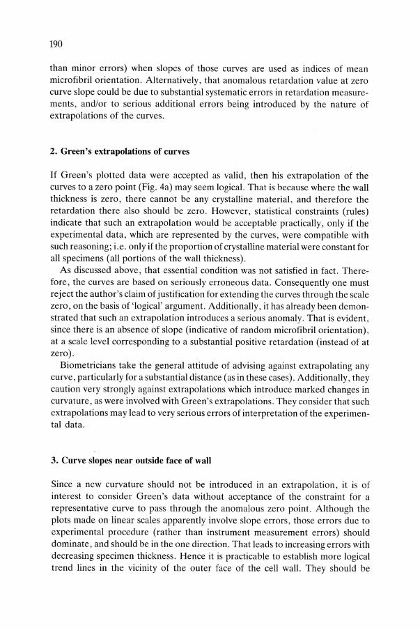
Since a new curvature should not be introduced in an extrapolation, it is of interest to consider Green's data without acceptance of the constraint for a representative curve to pass through the anomalous zero point. Although the plots made on linear scales apparently involve slope errors, those errors due to experimental procedure (rather than instrument measurement errors) should dominate, and should be in the one direction. That leads to increasing errors with decreasing specimen thickness. Hence it is practicable to establish more logical trend lines in the vicinity of the outer face of the cell wall. They should be
191
comparable for the different cells at each growth stage, although not indicative of actual values.
Accordingly, in the absence of Green's actual data, and information on the thickness of the cuticle, Fig. 4b was developed by first eliminating Green's curves from his plots of the data. Then curves were fitted by eye (as were those by Green). Except close to the minimum thickness positions for which data were obtained, i.e. up to where Green's extrapolation to zero had an overpowering influence, the latter curves and Green's show good agreement.
However, before making comparitive extrapolations to zero thickness, while minimizing grounds for statistical objection, it was noted that Green made two measurements of retardation for each of several optical thickness values. Often those paired values were substantially different. Evidence of such experimental 'errors' (variations) is apparent at a number of positions for the 51-mm-Iong cells (Fig. 4a). Hence, to help minimize bias due to experimental error, at unpaired points at positions of minimum measured thickness, large experimental differences for other pairs, at particular optical thickness positions in the same cell, were plotted (with obviously different identification marks) below those unpaired points (Fig. 4b). That direction of plotting those 'experimental error points' was determined by the general slope of the curves, through all the data for the greater thicknesses. It was chosen on the basis that the actual measurement and its paired 'error' (estimated) point would tend to straddle a 'best fit' curve, without a sharp change of curvature there.
It is of interest that, when such curves were imagined as extrapolated with maintenance of the rate of curvature change indicated by the whole range of data (Fig. 4b), then:
(i) for cells of all lengths, the curve slope up to the outer face of the wall was in each case indicative of negative retardation, or dominantly transverse orientation,
(ii) for the three fully-grown cells, each of those extrapolations intersected the ordinate through zero thickness at about the same scale position (an anomalous positive retardation value of about 15 A); that compares with 'paired' values of experimental data which showed differences of that much or sometimes much -more at various thicknesses;
(iii) it appears that curve slopes, at the ordinate through zero thickness, could be approximately the same for cells from 2 to 59 mm long. Coincidentally, Gertel and Green's (1977) data support this. That indicates an absence during extension, of reorientation of microfibrils from an initial transverse, at the inner face of the wall, towards axial at the outer face, and thus a lack of data showing support for MGH; and
(iv) for the youngest cells, the positions of intersections, between curves and the ordinate through zero, were nearer the nominal zero for retardation values, than were those for older cells; that could be a consequence of differing influences of the experimental procedure.
192
4. Microfibril orientation indicated by micrograph of polarized light effects
Green (1960a) also considered that his published micrograph, showing polarized light effects near the outer face of the cell wall (the thin edge of a wedge-shaped tear through the wall), indicated axial orientation there. However, that micrograph presents several anomalies associated with the 'brighter-than-background' image, that is parallel to the outer edge. Despite the appreciable width of that strip, presumably involving a substantial difference in thickness across that 'wedge-shaped tear through the wall thickness', there was no discernible difference in light intensity across the strip.
With MGH however, differences in polarized light responses would be expected, as inner microfibrils would be progressively less reoriented towards axial. Furthermore, calculations such as illustrated in Appendix III and Tables 4 and 5 show that, according to MGH microfibril orientation would change very rapidly towards axial, over a small portion of the wall thickness adjacent to the outer face. If it occurred, that should be obvious in a micrograph such as that published by Green. The wide strip of light of uniform brightness indicated lack of such orientation changes.
Additionally, there was an approximately uniform appearance of closelyspaced, transverse, tooth-like projections on both sides of the bright strip. One could conceive that such a serrated appearance may arise from broken ends of transverse microfibrils, but not from axial microfibrils parallel to the edge. It was notable also that, despite the wedge shape of the specimen, there was no graduation of intensity of light to indicate a gradual transition into the uniform dark grey image of a wide strip towards the inner face of the wall. Each of those features appears anomalous in respect of the claimed MGH type of progressive reorientation.
Correspondingly, it seems possible that the bright strip is an artifact, resulting from a 'halo' or edge reflection effect, and that it has a questionable relationship to microfibril orientation. Also, the appearance of closely-spaced transverse corrugations, near the outer face of the cell wall, seems incompatible with the relatively high stiffness, that would be associated with Green's postulation of axiallY-Qriented microfibrils there, in a direction at right angles to those corrugations. The corrugated effect could be compatible with a transverse microfibril orientation at the outer edge, but such a situation conflicts with the suggestion that the brightness of the strip, parallel to the edge, is a consequence of polarized light interaction with axial microfibrils there. Also, if the microfibrils were at a transverse orientation near that edge, that of course would be in conflict with MGH.
In respect of the bright strip of polarized light parallel to the thin outer edge of the specimen, Frei and Preston's (1964b) observation could be highly relevant. They stated that 'in surface view the cuticle is isotropic, though slight stretching is sufficient to render it positively birefringent with respect of the axis of strain'.
193
Hence the bright strip may be due to axial stretching of the cuticle layer of amorphous material, rather than axial microfibrils. Additionally, if transverse fragments of original transverse and somewhat separated microfibrils were present (and possibly covered with cuticle material), they would be sparse, and therefore would not affect the general high birefringence effect. On the other hand, their stiffness, in association with a slight viscous flow (sag) of the cuticle material between them, might account for the observed, transverse corrugation effect. That situation of course could not be claimed to support the hypothesis of MGH type reorientation of microfibrils.
Frey-Wyssling's (1976) diagram, showing birefringence of the Clivia epidermis, is reproduced herein (Fig. 5). It illustrates Frei and Preston's (1964b) observation that stretching of the cuticle layer is sufficient to render it positively birefringent. Thus the forced flow of the cuticle layer, to spread it over the increased surface area of the wall during cell extension, could introduce a birefringence effect in combination with transverse microfibrils in the crystalline portion of the wall. Hence Green's presumption, that the bright strip was due to axial orientation of microfibrils at the outer face of the wall, may be a consequence of misinterpretation of an effect due only to the cuticle layer. As discussed in the general text, there would be some restraint on freedom of flow of cuticle material at the layer boundaries, relative to the part between; that might account for the apparent corrugation effect at the boundaries.
Appendix V
Alternative models for extension of cell walls
Attempts to understand reasons for the nature and direction of the extension of cell walls, during growth, have traditionally been based on deductions from a (supposed) 'representative' model. For many years, an isotropic cylinder was accepted as the traditional basis of an appropriate model. The suitability of that model will be compared to that of a proposed alternative model, which involves the characteristics of a helical spring.
1. The isotropic cylinder model
The isotropic cylinder was proposed as a model by Castle (1937) and van Iterson (1937). Since then, it has remained without serious challenge, beyond some suggestions that it involves anomalies. On the basis ofthis model, both Castle and van Iterson pointed out that the stress tending to extend the cylinder (and presumably also the cell) axially is pR/2b; where 'p' represents the turgor pres-
194
sure, 'R' is the radius of the cylinder, and 'b' is the thickness of the structural wall. Similarly, the stress tending to extend the cylinder radially is pRib. Those stresses indicate that there is twice as much tendency to extend in the transverse direction as there is in the axial direction. Oddly, that situation has remained anomalous for nearly 50 years. No satisfactorily explanation has been offered for accepting the isotropic cylinder as a model for the cell wall, having regard to the fact that extensions of cells axially are generally much greater than transverse extensions.
The axial and transverse stresses in an isotropic cylinder must be related to the equation:
(e.g. Timoshenko, 1940); where 'strain' is defined as the extension per unit length of the material under stress, stress is the force per unit area, and 'E' represents Young's modulus of elasticity for the material (an indicator of its rigidity).
Hence the extension 'e' over the full length 'L' of the cylinder is given by:
. . stress X L LpR 1 k j
e (axtal) = stram x L = E = 2b x E = E '
where k j is a constant for that radius, length and thickness of the cylinder, and that pressure.
2. The helical spring model
The concept leading to the proposal of the helical spring model is based on the following observations. Generally microfibrils are formed in very long continuous lengths relative to the diameter or cross-sectional dimensions of the cell. Furthermore, in tubular cells the microfibrils are oriented in helical paths in the wall. Such helical orientations may be close to transverse, close to axial, or somewhere between. Observation of those characteristics have been reported in many research papers (e.g. Preston, 1938; Frei and Preston, 1961a,b; Probine and Preston, 1961; Balashov et aI., 1957; Bohmer, 1958); and in technical reviews such as those referred to in the introduction to this text.
Such arrangements of microfibrils may be conceived as inter-meshing, parallel, helical springs. Groups of them may act together, one inside the other. Within that composite spring form, some of those parallel groups may have a left hand helical rise, and some a right hand rise. All are compatible, and forces supported by each unit in the composite group will be determined in proportion to the relative stiffnesses (Timoshenko, 1940).
A helical spring model of the wall of an extending cell is represented in Fig. 2. There are numerous text books on simple structures and materials (e.g. Timoshenko, 1940), which develop the equations for estimating the axial extension of
195
such springs. It is shown that, for a spring as represented in Figure 2b, its extension 'e' is given by:
. 21mPR3 e (axIal) = sbc3G '
where 'n' is the number of helical turns ofthe spring (each through 360°); 'P' is the effective axial tension, or end force due to turgor pressure, i.e. P = 1TR2p for a cell of radius 'R' and turgor pressure 'p'; 'b' and 'c' are the effective radial width and axial depth respectively, of the spring winding material; and in this model, a closely-packed rectangular group of microfibrils is represented by each coil of the spring as illustrated (Fig. 2b); 's' is a constant determined by the shape of the coil material (ratio blc for a rectangular form), and its numerical value is in the range 0.14 to 0.33; and 'G' is the modulus of elasticity in shear, for the material constituting the coils.
If the helical turns are imagined as in the position forming a closed spring, i.e. each turn initially in side-to-side contact with the next helical turn above and below it (as if constituting an cylinder), then n = Llc, where 'L' is the length of the spring. Accordingly for that condition, the formula for axial extension of the spring can be written as:
. LpR 41T2R4 1 e (axIal) = -- x -- x-
2b sc4 G
3. Comparison of isotropic cylinder and helical spring models
For a comparison of the alternative models, the axial extension of the spring model can be written as:
k X k 41T2R4 e (axial) = _I __ S • where k =--
G' S sc4
Obviously ks is a constant for a given radius of helical spring, which is wound with coil material of rectangular section, represented by thickness 'b' (radially) and depth 'c' (axially). Hence the ratio, of the extension axially of the helical spring model, to that for the cylinder model is given by:
e (spring) = kj X ks -:- 5 = k x ~ . e (cylinder) G E s G
The modulus 'E' for the microfibril material particularly, and also 'E' for the matrix material are each much larger than 'G' for the respective materials (Table

196
3). Also, 'E' for the microfibril material overwhelms 'E' for the matrix material, as a determinant of strength reactions ofthe cell wall (see the general discussion). Additionally, ks must have a numerical value much greater than unity. Therefore the axial extension of the helical spring model must be considerably greater than that of the isotropic cylinder model. The minimum appropriate E values (Table 2) relate to a transverse orientation of microfibrils, and these lead to E/G values of much more than six (Table 3). Accordingly, for a given turgor pressure and thickness of the wall of the cell, the helical spring model is indicative of an axial extension of the cell that is much more than six times that indicated by the isotropic cylinder model.
The great weakness of the isotropic cylinder model has been its incompatibility with responses of tubular cells, which are extending by surface growth. Generally those cells increase in length at a considerably faster rate than they increase in width; e.g. about 5 to 1 in Nitella (Appendix I; Green, 1954; Probine and Preston, 1961). However, the transverse stresses in an isotropic cylinder are twice the axial ones and therefore, according to that model, the cell would tend to extend (deflect or strain) twice as much transversely as axially. For that reason, the isotropic cylinder model is quite inappropriate to represent characteristic responses of typical cell walls, as they are extended by surface growth (or by tip growth).
On the other hand, since the transverse extension of this closed helical spring model would be similar to that of an isotropic cylinder model of equal radius and wall thickness, the corresponding axial extension of the spring model would be more than three times the transverse extension shown by the cylinder model. As seen from Table 3, the E/G ratio for the microfibrils is likely to have a considerably greater value than six. Accordingly, the relative axial and transverse extensions indicated by the spring model could be highly representative of extensions in the two directions in cell walls. That would apply whether the microfibril material were cellulose, or some other crystalline polysaccharide.
Appendix VI
Strain stimulation for microfibril orientation In epidermal cells
An analysis of strain patterns, in a simple model of an epidermal cell, can indicate the significant features that would stimulate or determine specific microfibril orientations. Assume that the epidermal cell can be represented by a model somewhat as indicated by the heavy outline in Fig. 15. Because of the simultaneous development of adjacent cells, the two radial sides and the ends are
197
mutually supported against a tendency for bending, or excessive strain developing outwards, as a consequence of the turgor pressure during extension growth.
The outer tangential face (represented at the top of the model by line ABCD) lacks any external restraint against bending strain outwards. The inner tangential face would have some support from cells to the inner side of it, but not the equivalent of the full mutual support that exists on the radial and end walls. Furthermore. as the radial walls diverge from the inner face. there is a possibility that if turgor pressure tends to curve the inner tangential face outwards, that would induce a reactive force in the tissue against that face. In turn, that reaction would tend to cause some outwards slip along the radial faces. and so reduce the amount of support for the inner tangential face. Simultaneous development of turgor pressure, in the complete annulus of epidermal cells in a petiole. would have the same effect.
Relative to the outer tangential face, assume: (i) that its length is something like two to four times (or more) greater than its width; (ii) through most of the period of extension growth, the wall is relatively thin and flexible, so that turgor pressure will cause it to curve outwards somewhat, in both the axial and transverse directions; (iii) most of its width (say part B to C, Fig. 15) will curve to approximate a circular arc of radius 'R'; (iv) transition curves will develop into the radial faces; the final parts of these are represented by circular arcs of radius 'r'; (v) for such a flexible wall, it would be reasonable for the ratio R:r = 4:1 (or greater); (vi) at early stages of growth, the wall consists of a thin network of microfibrils, as at the isodiametric stage of development; i.e. it has equal strength in all directions, before the tabular form is developed. Assume additionally; (vii) that at early stages the microfibrillar network provides the minimum necessary support for the plasmalemma; and it is of thickness 't'; and (viii) turgor pressure 'p' is developed to induce extension growth.
During early stages of extension growth, with the outer tangential wall of the cell of uniform strength and rigidity in all directions, the sections AB and CD of the wall would tend to develop transverse stresses similar to those in an isotropic cylinder of radius 'r'. Correspondingly, section BC would tend to develop transverse stresses, as in a cylinder of radius 'R'. Hence for sections AB (or CD), and BC respectively:
(i) the ratio of their transverse stresses is 2rp/2t : 2Rp/2t = 1:4; (ii) the ratio of simultaneous axial stresses depends on the total area of the end
wall and its perimeter; i.e., it is virtually independent of differences between 'R' and 'r'. Hence the ratio of axial stresses on sections AB and BC is 1:1 (approx.);
(iii) from B to C, the ratio of transverse to axial stresses (on the assumption that stresses in the tabular cell approximate those in a tubular cell) is 2:1 (approx.);
(iv) on the basis as in (iii), the equivalent ratio of transverse to axial stresses for sections AB and CD = (1/4 x 2) : 1 = 0.5: 1.
198
Accordingly, the foregoing simplified basis of analysis indicates that in the initial stage of growth, with the wall reacting to stress like an isotropic material, the dominant stress (and strain) vector, which would be imposed on the plasmalemma, must be transverse for the section from B to C, and axial for the outer edges AB and CD of the tangential wall. However, that analysis does not take account of the fact that, simultaneously with bending in the transverse direction, turgor pressure causes the tangential wall to curve out in the axial direction, to become slightly dome-shaped. The stress pattern associated with that deflection tendency can be determined.
Again consider the early reactions, when the wall tends to act as if it were isotropic. The simplest basis of analysis is to regard the wall as a reactangular 'plate', which has turgor pressure imposed normal to its face, while it is supported at its outer edges by the radial walls and the end walls. Imagine that the wall is divided into strips of unit width parallel to its long sides, and into an alternative series of such strips parallel to its short sides. The stresses in each system of strips can be estimated, by taking note of the fact that if each strip is considered separately, the deflection in crossing strips must be equal at each intersection. The development of the formulae which indicate the bending moments, from which stresses and strains can be calculated, are set out in a number of text books (e.g. Eshbach, 1952).
Assume first that the wall has flexibility, such that at the supporting radial walls it cannot be held so rigidly as to prevent any significant rotation of its edges. Then for the alternative length-to-width ratios of 2 to 1 and 4 to 1, Eshbach indicates that the respective ratios of maximum strains, parallel to the short and long sides of the tangential wall, will be 3.8 to 1 and 5.8 to 1 respectively. Those relative maxima occur at the centre of both spans. Additional comparable calculations show that, if there were significant restraint against the rotational tendency at the edges, the comparative strain ratios would be reduced by 10 to 20% approximately. Overall then, it is apparent that bending of the outer tangential wall, by the turgor pressure normal to its surface, would induce at least 3 to 5 times more strain parallel to the width, than that parallel to the length of an isotropic fabric.
Thus the stresses in the tangential walls, due to turgor pressure in the direction perpendicular to the walls, would cause strains to develop in an elongated, domelike pattern of intensity. Indeed, because of the overpowering influence of stresses parallel to the width, relative to those parallel to the length of the wall, the contour pattern of intensity of strain would become more like that of an axially-directed ridge. Thus the maximum strains, along the length of the central ridge, would fall away towards zero strain at the supported edges, if curvature of the face were not rigidly restrained there.
However, consider the transverse compound curvature, which the wall must tend to assume as a result of the radial walls actually applying some constraint. The analysis above showed that the resulting maximum axial strain would occur at the edges, and taper off from there, through a curvature transition some

199
distance from the long edge. Overall then, the combined effects would be to average out the axial strains, to something approaching a uniform distribution across the width of the tangential face.
It is now practicable to define the stress vector, which reflects the principal strain.that arises from the transverse effects of turgor pressure on the tangential wall. That vector must be determined by the interaction of the lines (contours) of strain maxima parallel to the side walls, and the lines of maxima of the much smaller strains transverse to those. The resultant direction of principal strain must be close to the axial direction. On the basis of an approximate mean ratio of intensities of 4 to 1, that direction would be about 75° above transverse.
In discussion earlier, of the physical stimulation that apparently determines the direction of microfibril orientation at formation, it was shown that orientation followed the contours of maximum strain. This was illustrated particularly for cells with transverse orientation, that were being extended predominantly in the axial direction. On that basis, the near-axial direction of principal strains, that arise from the transverse bending effect of turgor pressure on the outer tangential walls of epidermal cells, would induce microfibril orientation in the near-axial direction. In respect of the inner tangential wall, the presence of some support or reaction against bending strain would lead to less stimulation for near-axial microfibrils there. At the same time, the virtually complete mutual support of the radial walls, by the adjacent epidermal cells, would result in little (if any) stimulus for microfibrils to be formed in a near-axial orientation in them.
The foregoing discussion, of the 'passsive' effects of turgor pressure acting in the transverse direction, takes no account of the active role of turgor pressure in stimulating extension growth of the cell. It was shown earlier, in relation to surface growth, that when the genetically-determined form of a cell involves extension dominantly in the axial direction, that is achieved most efficiently with a system of microfibrils helically directed at a small angle above transverse. Obviously the axially-oriented microfibrils, that would develop in the tangential walls, would not facilitate the required axial extension efficiently. Hence an independent system of microfibrils, to meet the need for axial extension of all side walls without imposing excessive strains on the plasmalemma, would be expected to develop in the _optimum transverse helical direction.
For such a dual system of microfibrils, when one was being built up into a significant layer in the tangential walls, the torsional force associated with extension growth would gradually change the direction of principal strain, until the tolerance level was exceeded. Then there would be a switch to the alternating system of microfibrils in the opposite direction of helical rise. With the gradual build-up of thickness of microfibrils in the second direction, and the associated increase in torsional force in the reverse direction, the resulting changes in the principal strain vector would reach a position where a switch back to the first direction was actuated.
However in respect of both systems, microfibrils would be formed only where
200
the strain on the plasmalemma was sufficient to stimulate their development. In these cells, axial microfibrils would not generally be formed in the radial walls, because of the lack of radial strain stimulus there. Although the physical factors, which lead to the axial orientation, were discussed (for simplicity) in respect of a wall structure that acted as if isotropic in nature, the same principles and similar results would apply for a wall which included a basic arrangement of transverse microfibrils.