xenon gladiator iv - ballantyne strong...
TRANSCRIPT

STRONG INTERNATIONALa division of Ballantyne of Omaha, Inc.4350 McKinley StreetOmaha, Nebraska 68112 USATel 402/453-4444 • Fax 402/453-7238www.strong-lighting.com
XENON GLADIATOR IVFollow Spotlight
Type 47070
Rev. September 2006

BULBWATTAGE
CURRENTRANGE (DC)
NOMINALCURRENT
DO NOTEXCEED
2000 50-90 A. 75 A. 90 A.2500 70-100 A. 90 A. 100 A.3000 60-110 A. 100 A. 110 A.4000 80-150 A. 125 A. 150 A.

PREFACE
STRONGINTERNATIONAL’SXENONGLADIATORIVModel47070isadirectcurrentfollowspotlightsystemcompletewithalamphouse,xenonpowersupply,opticalsystem,colorboomerang,andbasestandassembly.Thespotlightassemblyconsistsofthearclamp,variablefocuslenssystem,colorboomerang,andbase.Theseparatexenonpowersupplycompletestheinstallation.OnlythesespecialpowersuppliesmanufacturedbyStrongInternationalcanbeusedwiththeGladiatorIV.Forinstallationandopera-tionofthepowersupply,seetheinstructionmanualfurnishedseparately.
THEXENONLAMPHOUSEutilizesaxenonbulbdesignedforhorizontaloperation,andadeep ellipse metal reflector, as a light source. The reflector operates in a fixed position, and is dichroic (“cold”) coated to reduce heat in the projected light. A lens blower and heat filter, mounted in the spotlight optical system,furtherreduceheatattheprojectionlensandcolormedia.
ONLY XENON BULBS specifically designed for horizontal operation should be used in this followspot.TheGladiatorIVlamphouseisdesignedtousetheLTIX-4500W-HSwattbulb,andreplacementbulbs (4000-4500 watt, not exceeding 4500 watts) must be certified as 100% interchangeable with this bulb. Lower wattage (2000-3000 watt Type “HS”) bulbs may be installed in the Gladiator IV using an optional anode supportcolletsuppliedbyStrong.Allrequiredbulbcablingandcontactclampsareprovidedinthexenonlamphouse,andbulbadaptersarenotrequired.
ADJUSTMENTCONTROLforthexenonbulbislocatedattherearofthelamphousebehindtheaccesscover.Theadjustmentscontrolthehorizontal,verticalandfocalmovementofthebulb.
INSTRUMENTATIONofthelamphouseincludesadigitalrunningtimemeterwithDCvolt-ageandamperagedisplay.A “wattage” readout on the digital display is an approximate figure and should not dictatethebulb’soutputsetting.The running time meter records the elapsed hours of the bulb (resettable), andthetotalhoursthatthespotlightsystemhasbeeninoperation.ArockerswitchcontrolslampON/OFF.
THELAMPHOUSECOOLINGBLOWERSareinternallywiredandoperateonACvoltagederivedfromthexenonpowersupply.Theseblowersarerequiredtomaintainasafeoperatingtemperatureatthebulbseals.Anadditionalblowercoolstheopticalsystemandcolorboomerang.Theblowersoperatecontinuouslyuntilthexenonpowersupplyisde-energized. THE LAMPHOUSE is supplied with a 13 foot cable containing the DC leads, the AC control wires,andthegroundwire.Thecableterminatesinamultiple-pin,quick-disconnectplugkeyedtomatewiththereceptacleonthepowersupply.
WHENTRANSPORTINGTHESPOTLIGHT,itisnecessarytoremovethexenonbulbandplaceitinitsoriginalshippingcontainertopreventbreakage.SeetheSAFETYPROCEDURESsectionfol-lowing,andpermitonlyauthorizedpersonneltohandlethexenonbulb.
IFATANYTIMEyouhaveasuggestion,ordesireaidinsecuringanticipatedresults,writedirectly to STRONG INTERNATIONAL, 4350 McKinley Street, Omaha, Nebraska 68112 USA, or online at www.strong-lighting.com.
XG4/001
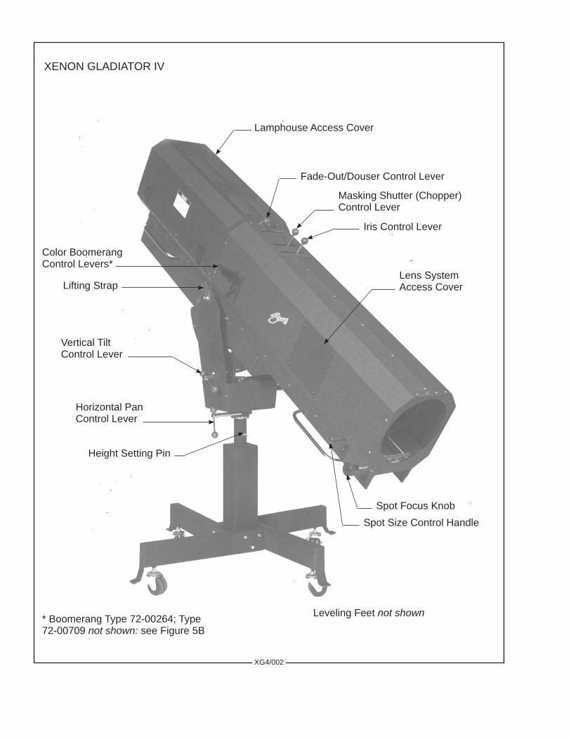
Lamphouse Access Cover
Fade-Out/Douser Control Lever
Masking Shutter (Chopper) Control Lever
Iris Control Lever
Horizontal Pan Control Lever
Vertical Tilt Control Lever
Height Setting Pin
Lifting Strap
Spot Size Control Handle
Color Boomerang Control Levers*
Spot Focus Knob
Leveling Feet not shown
Lens System Access Cover
XENON GLADIATOR IV
XG4/002
* Boomerang Type 72-00264; Type 72-00709 not shown: see Figure 5B

INSTALLATION AND SETTING UP SPOTLIGHT
THEXENONGLADIATORIVisshippedinsectionswhichmustbeassembled.Liftingstraps on the yoke assembly permit completely assembling the spotlight on the floor and later hoisting it to an elevatedposition.
ASSEMBLETHEFOURBASELEGStothelowersquaresectionofthebasecolumnusingthe 3/8-16 x 2-3/4 inch hex head cap screws and lockwashers provided. Insert a leveling foot and locknut in eachofthefourlegbracketsandlevelthebasebeforecontinuingtheinstallation.
WHENINSTALLEDinapermanentlocation,thecastersandlevelingfeetmustberemoved,and the clearance holes in the base leg brackets used for hardware (user supplied) to bolt the base to the floor orplatform.Ifitisdesiredtohavetheunitportable,whenoperating,thelevelingfeetmustbeadjusteddownuntiltheweightofthespotlighthasbeenshiftedfromthecasterstothelevelingfeet.
THEINNERTUBEofthesupportyokehasthreeholestopermitadjustingtheheightofthespotlight. The three holes are on four-inch centers and will allow an optical height of approximately 53 inches, 57 inches, and 61 inches above floor level to the optical center of the lamphouse and lens system. Insert the heightlocationpinthroughtheholeintheoutertubeandoneoftheholesintheinnertube.Thelevelingfeetmaybeadjustedthroughanadditionaltwo-inchrange.
THE HORIZONTAL SWING and vertical tilt locking knobs are on the right hand (operating) sideoftheyokeassembly.Leveltheyokeandtightenbothoftheselockingdevicessecurelybeforeattemptingtoplacethelamphouseandlenssystemonthesupportyoke.
PLACETHELAMPHOUSEandlenssystemontheyokeassembly,withthespotsizecon-trol handle to the right hand (operating) side, the same as the locking controls on the yoke. Line up the four tapped (5/16-18) mounting holes in the bottom of the base rail mounting bracket with the four mating holes in the support yoke and secure using the four 5/16-18 wing screws. Note the mounting holes are slotted to allow fine adjustment for balancing the spotlight.
ATTACHTHELAMPHOUSECABLECONNECTORtothematingreceptacleonthepowersupply.Thelamphouseandpowersupplyconnectorsarekeyedforcorrectpinalignment;makecertainpinsareseatedbeforetighteningthelockingring.DONOTenergizethexenonpowersupplybeforethexenonbulbiscorrectlyinstalledintothelamphouse.
XG4/003

LAMPHOUSE - POWER SUPPLYInterconnection Diagram
LAMPHOUSE(Connections Pre-wired)
MS CONNECTOR Pin Wire No, A DC- B DC+ C 2 D 3 E 4 F 5 G 6 I 7 J 8 M Grnd
LamphouseCable Assembly
XENON POWER SUPPLY
Connector (pre-wired)DC+DC-
SYSTEM MUST BE GROUNDEDAll wiring must conform to local codes;
shield lamphouse cable in conduit if required.
Check Slide Switch (below) on Power Supply for correct positioning.
Slide to LEFT
XG4/004

SAFETY PROCEDURES
READ CAREFULLY BEFORE INSTALLING XENON BULB
THEXENONBULBishighlypressurized.Whenignited,thenormaloperatingtemperatureofthebulbincreasesthepressuretoalevelatwhichthebulbmayexplodeifnothandledinstrictaccordancetothemanufacturer’soperatinginstructions.
THEBULBisstableatroomtemperature,butmaystillexplodeifdroppedorotherwisemis-handled.Breakageresultingfromtransportandhandlingisnotcoveredbythebulbmanufacturer’swarranty,anditisstronglyrecommendedtodismountthexenonbulbwhentransportingthespotlight.
REFERbulbreplacementandservicetoQUALIFIEDPERSONNELwithadequateprotec-tive clothing (face shield, clean cotton gloves, welder’s jacket). For routine lamphouse service, observe the followingrules:
1. Allow the bulb to cool to room temperature before opening the lamphouse. Put on protective clothing describedabove.
2. De-energize the xenon power supply at the AC source before opening the lamphouse compartment.
3. When possible, encase the bulb in its protective cover when cleaning or servicing the lamphouse interior.Thebulb,whenoutsidethelamphouse,mustbeencasedinthecover.
4. Cleanthebulbafterithascooledtoroomtemperature.Donottouchthequartzenvelopeofthebulb;fingerprints will burn in and create hot spots which may shorten bulb life. If fingermarks are made, theyshouldbecarefullyremovedwithmethylalcoholandcottonpriortobulboperation.
5. Neverviewanignitedbulbdirectly.BLINDNESSORPERMANENTEYEDAMAGEMAYBEINCURRED.
6. Use only xenon bulbs designated as OZONE FREE. When possible, vent the lamphouse exhaust to outsideatmosphere.
7. Maintain the lamphouse blowers in good operating condition. Keep the blower inlets and grilles clean for unrestricted air flow.
8. To insure maximum bulb life, operate the lamphouse blowers for at leasttenminutesafterextinguish-ingthebulb.
9. Ifreturningabulbforwarrantyadjustment,packitinitsoriginalshippingcontainer.Completeandreturnallrequiredwarrantyinformation.
XG4/005

10. Dispose of expired bulbs that are beyond warranty in the following manner: Wrap the bulb tightly inseverallayersofcanvasorheavycloth.Placeitonahardsurfaceandshattertheenvelopewithasharphammerblow.DONOTplaceanunshatteredbulbinanordinaryrefusecontainer.
11. DO NOT PERMIT UNAUTHORIZED PERSONNEL TO PERFORM OR ATTEMPT ANY PHASE OFXENONBULBHANDLINGORSERVICE.
Cathode PinCathode
AnodeAnode Pin
Cathode End Cap
Seal
SealEnvelopeAnode End Cap
XG4/006
For use in a Gladiator IV lamphouse, it is necessary to remove the anode lead (if attached) from the anode end cap of the xenon bulb. Observe all bulb safety procedures and leave the bulb in its protective cover. Grasp the bulb by the anode (+) end cap. Use small channel locks or slip-joint pliers and grip the bulb lead fitting at the crimp joint nearest the end cap, and unscrew the lead. If the bulb manufacturer uses a brazed rather than threaded connection, cut the lead from the end cap, cutting as close as possible to the end cap.
The standard bulb support collet (72-00285) measures 4-11/16 inches (120mm) overall and is designed for a 4000 watt “HS” xenon theater bulb. When using a smaller, lower wattage bulb, a longer support collet (72-00638) measuring 6-7/16 inches (164mm) must be installed in place of the standard collet, and a chromed cathode adapter (72-01174) must be mounted to the bulb’s cathode pin. These components are included in the optional Bulb Kit 72-01175, and both should be installed before performing the Bulb Installation procedure.
PRIOR TO INSTALLING BULB, PLEASE NOTE:

BULB INSTALLATION
OBSERVEALLSAFETYPROCEDURESwhenworkingaroundthexenonbulb.Openthelamphouse access cover by releasing the clasps and swinging the cover up to its stop. Loosen the (5) quarter-turn fasteners and remove the two bulb compartment side covers. Verify that the lamphouse is fitted with the correctsupportcolletappropriatetothedesiredbulbwattage.Thebulbleadsandcontactclampsaretieddownforshipping.Freetheclampsandslidetheanodeclampoverthebrasssocketoftherearsupportcollet.
REMOVETHEPLASTICPROTECTIVECOVERfromthexenonbulbonlyifnecessary.Handlethebulbbythemetalendcapsonly. Dismount the anode lead from the (+) end cap of the bulb if attached. Grasp the bulb by the metal anode (+) end cap only whenunscrewingtheleadfromthebulb;DONOT hold the bulb at the cathode (-) end cap when removing the anode lead.
INSERT THE BULB into the lamphouse, passing the anode (+) end cap through the center hole of the reflector. Take care not to bump or scratch the surface of the reflector. Insert the anode (+) pin into the rear support collet and contact clamp. Rest the cathode (-) end cap in the front bulb support yoke. Seat the anode (+) pin into the rear support collet as far as possible for correct focus travel. Securely tighten the socketheadclampingscrewintheanodecontact.
REST THE CATHODE END CAP in the “V” of the bulb yoke. Dress the bulb lead directly in frontofthebulbsupportyoketominimizetheprojectedshadow,butdonotallowittotouchgroundedmetallamphousecomponents;thebulbyokeandthesupportcastingareinsulatedfromground.Slidethecathodecontact clamp over the cathode (-) pin and securely tighten the clamping screw.
REMOVETHEPLASTICCOVERfromthebulb.Recordthebulbserialnumber,date,andlamphousehoursontheXenonBulbRecordontheinsidebackcoverofthismanual.Replacethebulbenclo-surecoversandsecurethequarter-turnfasteners.Useofthesecoversmaximizesbulbcoolingforlonglife.
XG4/007
Rear Support ColletBulb SocketAnode Contact Clamp
AnodeClamping Screw
to Igniter Post
Cathode
Front Bulb Support Yoke
Set Screw
Cathode Contact Clamp
to Negative Binding Post
Cathode Adapter (as req’d.)*
* Cathode Adapter & longer Rear Support Collet are included in the optional Bulb Kit 72-01175 required for 2 kW, 2.5 kW, and 3 kW bulbs.

ESTABLISHAROUTINEofperiodicallycheckingallelectricalconnectionsfortightness.Loosecontacts,particularlyintheDCcircuit,willcauseoverheatinganddamagethexenonbulbandothercomponents.Normalxenonbulbwarrantiesallowno creditforbulbdamagecausedbyoverheating.
REFERTOTHEBULBMANUFACTURER’SINSTRUCTIONSregardingbulbrotation.Most bulb manufacturers recommend rotating the bulb 180° at 50% of warranty hours. After rotating the bulb, operateatmaximumallowablecurrentforseveralhours,andthenreturntothenominaloperatingcurrent.
INTHEEVENTofabulbwarrantyclaim,thebulbmustbepackagedinitsoriginalshippingcontainer,andreturnedwithallrequiredwarrantyformscompleted.ContactthedealerthroughwhomthebulbwasoriginallypurchasedforcorrectproceduresandReturnAuthorizations.
ITISACOMMONPRACTICEtoreplacethebulbattheexpirationofitswarrantyperiod.If a xenon bulb explodes in operation, the reflector and other lamphouse components are frequently damaged. Thexenonbulbmanufacturerwillextendno credit for a replacement reflector if the defective bulb is beyond warranty. Explosion-damaged reflectors are to be returned to the bulb supplier,NOTStrongInternational,unlessthebulbwassuppliedbyStrong.
XG4/008
ARC STABILIZATION MAGNET
THEXENONBULBusedintheGladiatorIVlamphouserequiresanarcstabilizationmag-net. This magnet is located below and behind the reflector. The magnet is preset at the factory and should notrequireadjustment.Shoulditbecomenecessarytoadjustthemagnet,thefollowingproceduremustbefollowed.Observeallbulbsafetyprocedureswhenworkinginthelamphousecompartment.
A NORMAL ARC should appear as shown in Figure “A,” and represents the correct magnet position. Figure “B” shows the position of the arc when the magnet is too low; Figure “C” shows the position of the arc when the magnet is too high. Condition “B” or “C” will cause arc flicker. If flicker is apparent in theprojectedspot,raiseorlowerthemagnetonitsslotsasrequiredtopositionthearcasillustratedinFigure“A.”
THEMAGNETmustalwaysbeinstalledwiththelongestportionofthemagnetup-permost (nearest the bulb), and with the NORTH (N) pole pointing toward the operator side access door. Reversing the magnet will cause bulb flicker, and may inhibit bulb ignition. In new equipment, the magnet isnormallyinthecenteroftheadjustmentrange.Changesinthemagnetpositionarerequiredonlytocorrectan improperly burning arc (Figure “B” or “C”).
ANY REPLACEMENT MAGNET should first be installed in the center position of the adjustment range. Raise or lower the magnet as required to center the arc as illustrated in Figure “A.”

OPERATION
OPEN THE BOOMERANG ACCESS COVER and verify that the round glass heat filter and ringassemblyisinstalledintothebracketmountedtothefadeoutanddousersupporthousing.NOTE:Thecoated side of the filter, with the XX or other marking, must be facing the reflector.
REMOVETHEPLASTICCOVERfromthexenonbulb.DONOTignitethelampwiththecoveronthebulb.Storethecoverforfuturere-use.Replaceandsecurethebulbenclosurecovers.
CLOSETHELAMPHOUSECOVERandsecureusingbothlatches.Turnonthemainlineswitchand/orcircuitbreakertoenergizethexenonpowersupply.Thespotlightblowerswillstartandoperatecontinuouslyuntilthexenonpowersupplyisde-energized.
PLACETHELAMP SWITCH in the “ON” position and the lamp will ignite. Check the reading on the lamphouse ammeter. Nominal current for the 4500 watt xenon bulb is 135 amperes. If using alowerwattagebulb,checkthedocumentationpackagedwiththebulbforitscurrentratings.DONOT,ATANYTIME,exceedmaximumratedamperage;the “wattage” readout on the digital display is an approximate figure and should not dictate the output setting.Outputcurrentisadjustedatthexenonpowersupply;seepowersupplymanualforinstructions.Operationofanewbulbisnormallystartedatthelowerendofitsrange,andcurrentisgraduallyincreasedasthebulbagestomaintainlightoutput.Duringtheignitioncycle,thedisplaywill also briefly indicate the high “no load” (open circuit) DC voltage applied to the xenon bulb for ignition. REMOVE THE REAR COVER above the instrument panel by releasing the (3) quarter-turn fasteners.Thisexposesthebulbpositioningcontrolsinthelamphousebackcasting.Tofocusthexenonbulbandobtainthebestlightonthestage,thetwomethodsoutlinedbelowarethemostsuitable.
MOVE THE SPOT SIZE CONTROL HANDLE (trombone) on the large lens carriage all the way forward to project the smallest spot possible; place the iris, masking shutters (choppers) and the fadeout douser blades in their full open positions. Project a spot to a wall or similar flat perpendicular surface opposite thespotlightposition.
XG4/009
THE CENTER SECTION of the bulbpositioning controls is a threadedmember thatfocuses the bulb in relation to the reflector. Turning thisadjustmentmovesthebulbinonlyoneplane,into or away from the reflector. Turning this section clockwise moves the arc away from the reflector. Thesmallknurledscrewtotheleftofthissectioncanbetightenedtolockthefocusingmechanismafterthefollowingprocedureshavebeencompleted.
THE LARGE THUMB SCREWS, oneither side of the focusing control, lock thehorizontal and vertical adjustmentmechanisminposition.

TURNTHECENTERFOCUSINGSECTIONofthebulbpositioningcontrolcounterclock-wiseuntilasmallblackspotisprojectedontothewall.Itmaybebesttorunthisadjustmentbothdirectionsto permit positive identification of the spot.
LOOSENTHETWOTHUMBSCREWS,oneoneithersideofthecenterfocusingsection,justenoughtopermitmanualmovementofthecompleteassembly.Thebulbpositioningcontrolwillnowmovearoundthesetwothumbscrews,andasthiscontrolisshifted,thesmoothshadowofthebulbelectrodecan be seen extending beyond the projected center hole in the reflector. The shadow of the electrode (black spot) must be centered in the projected hole of the reflector (shaded, less dense dark area).
MOVETHECONTROLSECTIONaroundthetwoscrewsuntiltheblackspotisasroundaspossible to project. It may be necessary to again turn the focus control to project a sharply defined black spot.
AFTER THE BLACK SPOT is as even around the outside as possible to project, and appears centered in the shaded reflector center hole (Spot “A”), tighten the two large thumb screws to lock the position of the mechanism. Turn the center focus control to obtain the brightest light with the best light distribution (Spot “B”) and continue to the defocused position (Spot “C”) to verify that the bulb is centered in the reflector.
IFTHECENTERBRIGHTSPOTtracksofftotheleft,right,top,orbottom,itmaybeneces-sarytorepositionthefrontbulbsupportyoketocompensate.Loosenthesetscrewinthesupportcastingandresettheyokeasrequired.Thehexnutmaybeusedtolocktheheightoftheyoke.Securetheyokewiththeset screw after the bulb tracks on a straight axis. Return the focus control to the desired Spot “B,” and rotate thespotfocuscontrolknob,locatedattheextremefrontofthelensmechanism,toobtainthesharpestedgepossibleontheprojectedspot.
XG4/010
THESECONDMETHODoffocusingthexenonbulbistoprojectthespottothestage,andworking with the above lamphouse controls, adjust these controls to obtain a “hot spot” on the projected spot. Center this “hot spot” on the projected light by moving the entire control section around the two thumb screws. Once this “hot spot” is centered in the projected light, lock the control in position with the two thumb screws andturnthecentersectiontoobtainaspotwithanevendistributionoflight.Rotatethelensspotfocuscontrolknobtoobtainasharpedgeontheprojectedspot.
THESEADJUSTMENTSshouldnotbedisturbeduntilafterreplacingorrotatingthexenonbulb. At that time, the procedure on obtaining a smooth, round black spot, or “hot spot,” may have to be repeated. Replace the cover plate over the bulb positioning controls and secure with the (3) quarter-turn fasteners.
BECAUSEOFNORMALBULBAGING,andmanufacturingtolerancesbetweenindividualxenonbulbs, itmaybenecessarytooperatedifferent lampsatslightlyhigheror lowercurrentsettingstoachievebalanced,uniformlightoutputwhentwoormorespotlightsareusedinoneinstallation.Thisentailsaslightcurrentoutputadjustmentatthexenonpowersupplies.Seethepowersupplymanual.

XG4/011
TO EXTINGUISH the arc, place the LAMP switch on the instrument panel to “OFF.” The lamphouseblowerswillcontinuetooperateuntilthexenonpowersupplyisde-energized.Allowtheblowerstooperatefortenminutesbeforeturningoffthepowersupply;aforced-airbulbcoolingcycleatshutdownisrequiredbyallbulbmanufacturerstocomplywiththeirwarrantyterms.
BEFOREOPENINGthelamphouseenclosureforservicing,allowtheblowerstooperatefortwentyminutes,oruntilthebulbhascooledtoroomtemperature.
HANDLING THE SPOTLIGHT
GENERALLYTHEBESTPOSITIONfortheoperatortostandisnearthecenterofthespot-lightontherightside.Theangleoftilt,thesizeoftheporthole,andthelayoutofthespotlightpositionmaydictateanotherlocation.
EACHOPERATORwill,afterafewminutesofoperation,generallydevelophisownsystemandpositionformostconvenientoperation.
THEHORIZONTALSWINGandverticaltiltareindividuallyadjustabletogivethedesireddegreeoffrictiontosuittheoperator.Thelockingclampsarelocatedontherightsideoftheyokeassembly.
ANEXPERIENCEDOPERATORwillusuallykeeponehandonthespotsizecontrolhandle.Thisallowsbothdirectingthespotandchangingspotsizesimmediatelyuponcue.Compressingthebrakeleverpermitsfreemovementofthelargelensforwardandback,andreleasingtheleverlocksthespotsizeatthedesiredpointoftravel.
Large Lens
Spot Size Control Handle
Brake Lever

OPERATION OF OPTICAL SYSTEM
THEIRISCONTROListhefrontleverwhichprojectsthroughthetopoftheopticalsystemhousing. When this lever is to the left (as viewed from the rear of the unit), the largest aperture is provided. Smalleraperturesareobtainedastheleverismovedtotheleft.
THE MAXIMUM FLOOD SPOT is obtained with the iris control lever to the right (near the op-erating side) for the largest aperture and with the spot size control handle moved as far to the rear as possible.
SMALLERSIZEDSPOTSareprojectedasthespotsizecontrolhandleismovedforward.Mostofthespotsizesneededwillbeproducedwiththeirisinitsmaximumopenposition.
FOR A “HEAD SPOT,” or any spot smaller than can be obtained with the spot size control handle in its extreme forward position, shift the iris control lever to the left (away from operating side) for a smalleraperture.Theiriscontrollevershouldalwaysbereturnedtoitsextremerightpositionbeforethespotsizecontrolhandleisagainmovedtoobtainlargerspots.
THE MASKING SHUTTER (chopper) lever is the middle lever projecting through the top of theopticalsystemhousing.Themaskingshutterbladesareoperatedbythislevertoshapetheprojectedspottoarectangle,stripspot,ordousing.
THE DISENGAGED POSITION of the masking shutter lever is to the extreme right (toward operating side) and varying degrees of masking to complete cutoff are obtained by moving the lever to the left (away from operating side). If dousing the spot for a prolonged period with the bulb operating, it is highly recommendedtousetheFadeout dousers (below) to prevent heat damage to the masking shutter blades.
THEANGLEofthemaskingshutterbladescanbeadjustedtocompensateforthehorizontalprojection angle. Remove the color arm cover plate and dismount the boomerang. Loosen the (4) screws holdingeachofthemaskingshutterbladesenoughtoallowadjustments.Ignitethebulbandadjusttheangleofthebottombladebytappingwithascrewdriversoitsprojectededgeliesparalleltothefootlights.Tightenthescrew.Operatethemaskingshutterlevertoclosetheblades.Adjusttheupperbladetocloseinlinewiththebottombladeandtightenthescrew.
THEFADEOUTMECHANISMANDDOUSERCONTROL is the rear lever projectingthroughthetopoftheopticalsystemcover.Thislevercontrolstheintensityoflightfromcompletefadeoutwhentheleveristotheleft,tofullintensitywhentheleveristotheright.
THESPOTSIZECONTROLHANDLEislocatedontherighthandsideoftheopticalsystemjust above the base rail. A variation of spot sizes from full flood to small spot can be obtained by moving the spotsizecontrolhandlefromoneextremetotheother.Beamintensityisincreasedbythisopticalsystemwhen reducing from flood to spot, and maximum intensity is reached when the spot size control handle is in theextremeforwardposition.Compressingthebrakeleverforwardofthehandlepermitsfreemovement.
THE SPOT FOCUSING CONTROL KNOB is located on the operating side of the optical systemattheforwardendabovethebaserail.Thiscontrolisusedtoadjusttheopticalsystemforthelengthofthrow.Whenmakinganadjustment,rotatethespotfocusingcontrolknobuntilthesharpestedgeisobtainedontheprojectedspot.
XG4/012

OPERATION OF COLOR BOOMERANG
THE COLOR BOOMERANG supplied with the Gladiator IV is selected when first ordering the spotlight from the factory. The Type 72-00264 boomerang is mounted within the optical system and uses (6) 50mm dichroic discs as the color media. Type 72-00709 mounts to the front of the lens barrel and uses conventional high-temperature color gels (i.e. Roscolux®) as color media.
EACH BOOMERANG is equipped with six color arms. A “starter” set of six 50mm dichroic colordiscs,orsixsheetsofcommonly-usedcolorgel,isincluded.Additionalcolors,includingcolortem-perature reduction filters, are available from most theatrical supply dealers.
COLORFILTERSarecontrolledbythesixcolorleversoftheboomerang.Toengageanindividual color filter, lower the desired filter selector lever. A rocker catch located in the color disc housing holds the filter in the light beam. To release a color, lower the filter release lever or engage another color, thus releasingthepreviouscolorautomatically.
TO REPLACE A COLOR FILTER in the 72-00264 boomerang (see Parts List, Figure 5A), it isrecommendedtodismounttheentireassemblyfromtheopticalsystemandplaceitonaconvenientworkingsurface. Loosen the (2) quarter-turn fasteners and remove the side cover plate. The entire boomerang assembly canthenbeeasilyremovedbylooseningthesinglecaptivescrewsecuringtheboomerangbrackettothebaserail, and lifting the bracket off the (2) locating pins. When re-installing the boomerang, align the holes in the boomerangbaseplateontothesepinsbeforeagainsecuringthecaptivescrew.
TO ATTACH A COLOR GEL to the color frame of the front-mounted 72-00709 boomerang (see Parts List, Figure 5B), spray the flat surface of the ring (without the channel clip) with an aerosol adhesive. Center the ring over a precut 13½ by 13½ inch (34 x 34cm) gel, and press the adhesive-coated side onto the gel.Trimtheexcessgelmaterialandinstalltheringintotheboomerang.Oldgelscanberemovedfromthecolorframebyscrapingthegelandadhesivefromtheframeusingasingle-edgerazorblade.
NOTE:WHENINSTALLINGCOLORFILTERSineitherboomerang,thelessdensecolors(pink, amber) should be placed in the holders toward the rear of the boomerang (close to the arc), and those ofgreater density (red, green) should be placed in the holders toward the front of the boomerang (away from the arc). This measure will prolong the useful life of the filters.
XG4/013

XG4/014
DIGITAL DISPLAY
UPONENERGIZINGtheLAMPcircuit,thebacklightingwillilluminatetheLCDscreen.ThedisplayCHECK TOP COVERwillappearifthetopcoverifnotsecured.Whenthelamphouseaccesscoverisclosedandcorrectlysecured,andtheblowersareoperating,thedisplaywillappearasshown:
000V 000A 0000W1234BLB 12345HR *
FORPURPOSESOFILLUSTRATION,theabovedisplayindicatesanon-operatingbulbwith 1,234 hours of use installed into a spotlight with 12,345 hours of operation. The asterisk (*) at the end of the second line, when flashing, indicates that the display is active and awaiting input. Upon bulb ignition, the upper line will display the arc voltage (V), the DC current (A), and the operating wattage (W) of the bulb. The “wattage” readout on the digital display is an approximate figure and should not dictate the DC output setting.The figures will shift for the first few moments of bulb operation, but will stabilize after the bulb reaches normal operating temperature and pressure. A plus sign (+) will replace the asterisk.
CLOSUREOFTHELAMPSWITCHwillenergizethecontactorofthexenonpowersupply.The high open circuit (“no load”) DC voltage will be displayed. When the open circuit voltage reaches 140 V.DC,theigniterwillgenerateaRFpulsetobridgethegapbetweenthebulbelectrodes.Thispulse,coupledwith the high open circuit DC voltage, will ignite the bulb. The voltage reading (V) will then fall to the bulb’s sustaining level, and the DC amperes (A) and wattage (W) will be displayed continuously until the bulb is extinguished.
ELAPSED HOURS will begin counting upon bulb ignition. Bulb hours (BLB) are limited to fourdigits,andmustbere-setwhenthexenonbulbisreplaced.Tore-setbulbhours,presstheRESETbuttonaccessible through marked hole below the LCD screen. The 5/64” allen wrench supplied with the accessory kitisthecorrectdiametertoclearthehole.
NOTE:WHENRECORDINGstart-upandremovalhoursontheXenonBulbRecord,usethetotal elapsed hours (HR) figures. The (BLB) figure, re-set upon installation of the bulb, is a convenience feature ONLY. Basing records of the lamp system on the total hours (HR) figures permits an accurate and ongoinghistoryofbulbusage.
IFTHEXENONBULBfailstoignite,thefollowingdiagnosticmessageswilldisplayonthelowerlineoftheLCDscreen:
CHECK PWR SUPPLY: If no DC current is sensed, and voltage does not exceed 125 V.DC, check the xenon powersupply.Repairorreplaceasrequired.
CHECK IGNITER: If the DC open circuit voltage reaches and exceeds 140 V.DC and the igniter fails topulse,replacetheigniter.
CHECK XENON BULB: ChecktheDCcablesconnectedto thebulb. If thehighvoltageisshortingtoground, and not arcing between the bulb electrodes, locate and correct (insulate) theshortcircuit.Ifthehighvoltagearcappearsbetweenthebulbelectrodes,andthebulbfailstoignite,replacethebulb.

XG4/015
DIAGNOSTICMESSAGESserveaspromptsandsuggestionsbutdonotreplacetraditionaltroubleshootingprocedures.Ifthetopcoverisclosedandsecuredbuttransmitsanerrormessage,checkthesubjectcoverinterlockswitchwithanohmmeterandreplaceifdefective.Dirtordustfoulinganairvaneswitch will cause a “blower” error message. A “power supply” or “igniter” error message might be caused by alooseoroxidizedconnection.

XG4/016
MAINTENANCE
THEXENONGLADIATORIVSPOTLIGHTrequiresverylittlemaintenancetokeepitingoodworkingorder.
THEREFLECTORshouldbecleanedperiodicallywithasoft,clean,lint-freeclothtore-move dust from the reflecting surface. If excessively soiled, the reflector may be cleaned with Windex®oranequivalent glass cleaner. DO NOT use abrasive cleaners of any kind. Clean the heat filter glass; replace with thecoatedsurfacetowardthelamphouse.
CHECK ALL ELECTRICAL CONNECTIONS for tightness on a regular basis. Loose connec-tions,particularlyintheDCcircuit,maycauseprematurebulbfailureanddamagelamphousecomponents.
LUBRICATE the (3) squirrelcage blower motors with two or three drops of non-detergent oil onceeverysixmonths.
THEXENONBULBshouldbecheckedoccasionally for thepresenceofdustor foreignmaterialsonthequartzenvelope.Ifnecessary,cleantheenvelopewithalcohol,andwipedrywithaclean,lint-freecloth.Observeallsafetyprocedureswhenworkingwiththeexposedbulb.
THEINSIDEOFTHELAMPHOUSEandtheblowersquirrelcagesshouldbecleanedperi-odically, depending on the dust conditions at each installation. Keep the blower inlet and outlet grilles clean to permit free air flow.
THELENSSYSTEMshouldbekeptcleantopreventanylightreductionintheprojectedspot.Tightenthehorizontalswingandverticaltiltlockingclamps.Removetheoperator-sideopticalsystemaccesspaneltocleanthebacksurfaceofthelargelensandaccessthesmallprojectionlenswhichisheldinplacewithalargespring-typeretainerringatthefrontofitslensbarrel.
CLEANTHEPROJECTIONLENSandlargelenswithwithanycleanerapprovedforuseoncoatedprojectionlenses.ReplacetheBuhlprojectionlenswiththeendwiththeFLmarkingringtowardtheiris;theISCOlenstubehasarrowsindicatingtheendnearesttheiris.Securewiththeretainerring.
BEFORETRANSPORTINGthespotlight,removethexenonbulbfromthelamphouse.Placethebulbinitsplasticcoverandoriginalshippingcontainer.
CAUTION: DISCONNECT AC POWER BEFORE SERVICING

LAMPHOUSE WIRING DIAGRAM
Barrier Strip 21-62012 (see Figure 3, Item 44)
XG4/017
XG4/018
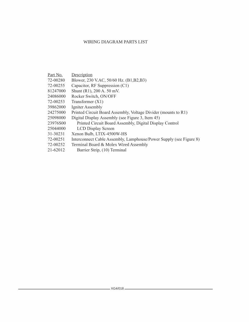
WIRINGDIAGRAMPARTSLIST
PartNo. Description72-00280 Blower, 230 V.AC, 50/60 Hz. (B1,B2,B3)72-00255 Capacitor, RF Suppression (C1)81247000 Shunt (R1), 200 A. 50 mV.24086000 Rocker Switch, ON/OFF72-00253 Transformer (X1)39862000 Igniter Assembly24275000 Printed Circuit Board Assembly, Voltage Divider (mounts to R1)25098000 Digital Display Assembly (see Figure 3, Item 45)23976S00 Printed Circuit Board Assembly, Digital Display Control25044000 LCD Display Screen31-30231 Xenon Bulb, LTIX-4500W-HS72-00251 Interconnect Cable Assembly, Lamphouse/Power Supply (see Figure 8)72-00252 TerminalBoard&MolexWiredAssembly21-62012 Barrier Strip, (10) Terminal

2397
6S D
IGIT
AL
DIS
PLA
Y C
ON
TRO
L C
IRC
UIT
Pag
e 1
0f 3
XG4/019

2397
6S D
IGIT
AL
DIS
PLA
Y C
ON
TRO
L C
IRC
UIT
Pag
e 2
0f 3
XG4/020
2397
6S D
IGIT
AL
DIS
PLA
Y C
ON
TRO
L C
IRC
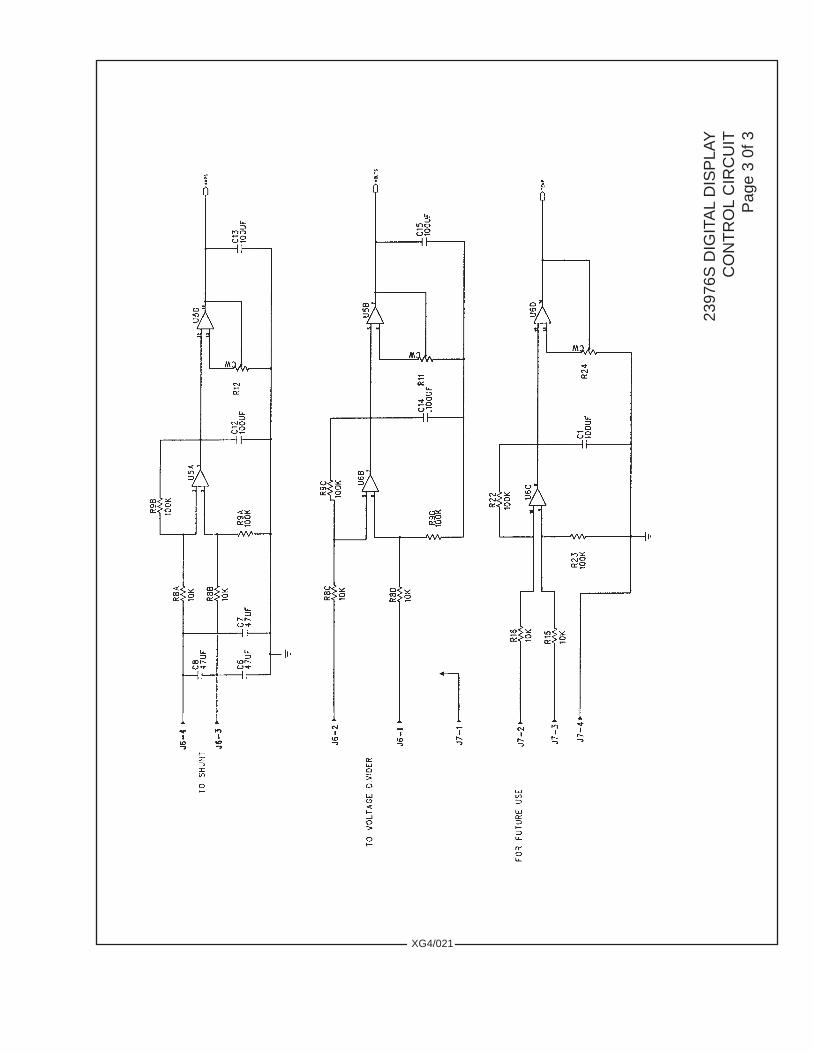
UIT
Pag
e 3
0f 3
XG4/021

24275 VOLTAGE DIVIDER BOARDmounts to R1 Shunt
Ref.Desig. PartNo. DescriptionC1-C5 61-08025 Capacitor, .005µf, 3 kV.D1-D4 51-17001 Diode, 1N4007R1 61-46002 Resistor, 100 Ohm, ¼ W. 5%R2 61-46045 Resistor, 100k Ohm, ¼ W. 5%J1 21-37051 Connector, (5) PositionNOTE: Replacement Board must be modified as shown above (cut jumper) or board will not function!
VOLTAGE DIVIDER ASSEMBLY
Cut this Jumper Wire before installing 24275 PC Board in Gladiator IV Lamphouse
XG4/022

XG4/023
TROUBLE CHART
NORMAL OPERATION
WHENTHESWITCHinthemainACsupplylinetothexenonpowersupplyisintheONposition, and the 30 A. circuit breaker on the switching power supply is ON, the POWER lights on the xenon powersupplyandthelamphouseinstrumentpanelwillglow.Thelamphouseblowerswillstart.Theblowersinthepowersupplywilloperate.
WHENTHELAMP SWITCH is placed in the ON position, the AC control circuit (2 & 6) inthelamphousewillenergizethepowersupplycircuitryprovidingDCcurrenttotheigniterandbulb.Thegreen “GO” light on the xenon power supply indicates a completed circuit.
THEREWILLBEadistinctlyaudiblehighvoltagearcpingattheigniterarcgapandacrossthebulbelectrodes.Thebulbshouldigniteimmediatelyafteroneortwoofthesehighvoltagepulses,andthelampcurrentwilladjusttotheoutputsettingofthexenonpowersupply.Multipleignitionpulsespriortobulbignition normally indicate a low DC output setting; increase output to the bulb’s initial (“nominal”) current setting; see xenon power supply manual. A “warm” or aged xenon bulb might also require multiple strikes.
TROUBLE SHOOTING
IFTHEXENONBULBdoesnotignite,observethefollowingoperationalsequencesforas-sistanceinlocatingandisolatingthetroublearea.
WHENTHEFANSandtheindicatorlightonthepowersupplyareon,thecircuitinthepowersupplyistrouble-freeuptotheterminalblockinthepowersupply.Atthistime,thespotlightblowersshouldoperate.Ifthisdoesnotoccur,thetroubleisinoneoftheblowermotors,alooseconnection,orabroken#7 or #8 lead (220 V.AC). Check at this time for 220 V.AC blower voltage at wires 7 & 8, and 220 V.AC at the lamphouse quick-disconnect pins 9 & 10. CAUTION:exerciseextremecautionwhentakingvoltagemeasurementsinapowerONcondition.
ADEFECTIVEDIGITALDISPLAYwillnotpreventbulbignition.
IF THE HIGH VOLTAGE PING or the ignition flash is not apparent, check voltages on the terminal board behind the display. A reading of 120-170 V.DC “no load” should be measured between #6 and #7, and 115 V.AC between #9 and #10. If these voltages are not indicated, the problem is in the leads between thelamphouseandpowersupply,orinthepowersupplyboostcircuit.Seethetroubleshootingsectionofthepowersupplymanualforadditionalinstructions.
THESWITCHING-TYPEXENONPOWERSUPPLYfurnishedwiththespotlightsystemincludesthermaloverloadswitchesandprotectioncircuitstopreventdamageresultingfromhighorlowinputvoltage.LossofDCopencircuitvoltage,oraninterruptionofDCsustainingcurrent,maybetracedtothesecircuits.Seethepowersupplymanual.
IFTHEHIGHVOLTAGEARCisaudibleatthelamphouseandthebulbdoes not flash, check foralamphouseDCleadarcingtoground.Ifnogroundfaultisdetected,replacethebulbandattemptignitionwiththenewbulb.

XG4/024
Bulb fails to ignite.
1. AC power not on to lamphouse. Turn switching power supply 30 A. circuit breaker ON. If 230 V.AC not read at 1 & 2, or POWER indicator not glowing, see power supply manual.
2. Faulty “ON-OFF” switch. Check for voltage at terminal block positions 9 & 10; check for loose terminalsorwiring.Replaceifdefective.
3. Low AC source voltage actuating “brownout” protection circuit in xenon power supply.
Bulb fails to ignite; ping audible, bulb flash visible.
1. Inadequate DC output from xenon power supply. Set power supply output to correct range required for bulb wattage (120-150 A. for 4000 watt). Do not exceed 150 A.
2. If bulb flash is visible but faint, check for defective printed circuit board in igniter. Replace if defective. 3. Faulty or expired xenon bulb. Replace as required.
Bulb fails to ignite; ping audible, no bulb flash.
1. Faulty xenon bulb. Check for cracked electrodes or darkened envelope. Replace if defective. 2. Ignition pulse shorting to ground. Inspect DC leads for burned insulation; dress leads away from
groundedmetalcomponents.
No high voltage ping audible; LAMP switch in “ON.”
1. Loss of AC control voltage. Check xenon power supply for tripped circuit breaker or open thermal switch.Seepowersupplymanual.
2. Lamphouse top cover interlock switch open. Top cover must be closed and both latches secured. 3. Xenon power supply “GO” light not glowing. See power supply manual. 4. Little or no DC “No Load” voltage. Measure DC “No Load” voltage at 6 & 7. See power supply
manual. 5. Open fuse F1 (10 A.) on switching power supply primary PC board. SEE POWER SUPPLY MANUAL.
Allow (20) minutes for capacitor discharge before replacing. 6. Loose spark gap connections or terminals. Repair or replace igniter PC board as required.
IF THE HIGH VOLTAGE ARC is audible at the lamphouse, the flash of the bulb is apparent, butignitionofthebulbisnotsustained,theproblemareaisinthepowersupply.Seethetroubleshootingsectionofthepowersupplymanualforadditionalinstructions.
IFTHEHIGHVOLTAGEARCisnot audible or the flash of the bulb visible, the problem is intheigniterassembly.
EXCHANGE of components (i.e. igniters, printed circuit boards) between similar Strong XenonGladiatorstoaidindiagnosisofaproblemisencouraged.Thiswillnotleadtoequipmentdamage,andwillnotvoidequipmentwarranty.
GLADIATOR IV TROUBLESHOOTING
EXERCISE ALL DUE CAUTION WHEN MEASURING VOLTAGES IN A “POWER ON” CONDITION

XG4/025
Digital Display not ON.
1. Check for loose connection on plug J5. 2. Check for 230 V.AC on terminal block positions 1 & 2. If correct, check X1 transformer output for
115 V.AC. If not measured, replace transformer.
Bulb goes out during operation.
1. Xenon power supply overheated; thermal switch open. Check power supply blower(s), air inlets and outletsunobstructed.Seepowersupplymanual.
2. Xenon bulb depressurizing. Check for envelope discoloration; replace if defective. 3. Fluctuating AC source voltage actuating brownout or spike protection circuits in xenon power supply.
Seepowersupplymanual.4. Lamphousecoverlooseoropen.Closeandsecure.
Noise in theatre sound as bulb ignites.
1. Faulty RF suppression capacitor(s). Remove and test C1. Replace if defective. 2. Lamphouse,powersupply,orsoundsystemnotproperlygrounded.Connecttoadequateearthground.
Excessive light flicker..
1. Faulty or aged bulb. Check for cracked or sagging electrodes; replace if defective. 2. Excessive ripple in DC output. See power supply manual. 3. Arc stabilization magnet reversed. NORTH pole should point toward operator’s side. Check with
compassifrequired.
Reduced light output.
1. Normal bulb aging. Increase output current. DO NOT EXCEED MAXIMUM CURRENT LEVEL SPECIFIEDBYBULBMANUFACTURER.
2. Soiled reflector. Clean using commercial glass cleaner; USE NO ABRASIVES. 3. Soiled heat filter, projection lens, or large lens. Clean as required. 4. Bulb or reflector position altered. Correct alignment; see preceding OPERATION section.
Extremely long duration between ignition pulses.
1. Low DC “no load” voltage from the xenon power supply. Check “no load” voltage; see power supply manual. 2. Defective spark gap. A “Ping” sound is normal; excessive “Hissing” is abnormal. Replace if defective.
Colors burning or fading prematurely.
1. Bulb focused to “hot spot.” Refocus bulb to flat field with iris fully open and spot size control handle (“trombone”) fully forward.
2. Heat filter glass reversed or peeled. Check for coatedsurfacetoward bulb;replaceifcoatingpeeled. 3. Reflector coating peeled. Replace if defective.

1
2 3
4
5
67
8
910
12
13
7
14
15
11
XG4/026
FIGURE 1

PARTS LISTFigure 1
Item PartNo. Description 1 72-00164 Lamphouse Top Cover & Access Panel - 72-00163 Side Cover, Off-Operator Side (not shown) 2 72-00247 Cover Plate, Optical System Controls (as shown) 2 72-01000 Cover Plate, Optical System Controls (no color arm slots) 3 10048A00 Knob 4 72-00207 Lens System Cover, Off-Operator Side 5 72-00175 Front Cover, Lens System 6 25064000 Lens Focus Knob 7 25221000 Hand Rail - 4310751 Mounting Screw, 5/16-18 x 3/4" - 4317000 Lockwasher, 5/16" 8 51509000 Handle, Spot Size Control 9 72-00246 Access Panel - 31-98209 Quarter-Turn Fastener (4 req’d.) - 31-98200 Receptacle, Quarter-Turn Fastener (not shown) 10 72-00206 Lens System Cover, Operator Side 11 72-00397 Bottom Cover, Front 12 4310753 Wing Screw, 5/16-18 (4 req’d.) - 4317100 Washer, 5/16" (4 req’d.) 13 72-00170 Bottom Cover, Rear 14 72-00162 Lower Cover, Lamphouse Access 15 31-18007 Clasp Latch (2 req’d.)
XG4/027

FIGURE 21
2
3
4
5
6
7
8
XG4/028

PartNo. Description39191000 Negative (-) Contact Clamp4080316 Set Screw, 8-32 x 5/16"4080870 Clamping Screw, 8-32 x 7/8"SocketHead4108001 Height Adjust Lock Nut, 10-32 Hex4250373 Screw, 1/4-20 x 3/8"HexHead70162000 Front Bulb Support Yoke (see Figure 3, Item 48)72-00281 Bulb Lead Assembly (complete set)72-00282 Positive (+) Contact Clamp72-00285 Rear Bulb Support Collet, 4 kW (see Figure 3, Item 53)72-00638 Optional Rear Bulb Support Collet, 2-3 kW72-01174 Optional Cathode Adapter, 2-3 kW
Item PartNo. Description 1 72-00160 Bulb Enclosure Top Cover, Rear 2 72-00159 Bulb Enclosure Brace - 00M15315 Arc Stabilization Magnet (not shown) - 81137000 Magnet Clamp - 4080259 Set Screw, 8-32 x 1/4" 3 72-00166 Bulb Enclosure Top Cover, Front 4 72-00173 Mounting Bracket, Fade Out Assembly 5 72-00258 Light Shield (see Figure 3, Item 14) 6 72-00167 Access Panel, Front 7 72-00161 Access Panel, Rear 8 31-98209 Quarter-Turn Fastener (5 req’d.) - 31-98200 Receptacle, Quarter-Turn Fastener (not shown)
PARTS LISTFigure 2
XG4/029
72-0028572-00638
72-00282
4080870 70162000
4080316
4108001
4080870
4250373
39191000
BULB MOUNTING COMPONENTS
72-0028172-00281
4080316 72-01174

12
3
45
67
8
109
1112
1314 15 16 17
1819
20 21 22
23 2425
26 27
28
29
31
32
33
34
3536
33
FIGURE 3
38 3940
41
42
4344
45
4950
51
52
5354
4647
48
27
30
37
XG4/030
19b
28a
Det
ail
19a

Item PartNo. Description 1 72-00658 Access Cover Plate - 4100504 Mounting Screw, 10-32 x 1/2" - 31875000 Thumbscrew, 10-32 2 72-00158 Lamphouse Back Cover 3 72-00155 Rear Lamphouse Bulkhead Plate - 4250752 Mounting Screw, 1/4-20 x 3/4" - 4257000 Lockwasher, 1/4" 4 21-61006 Interlock Switch & Lead Assembly - 4040500 Mounting Screw, 4-40 x 1/2" 5 21-98544 Magnet, Switch Actuator (mounts to Figure 1, Item 1) 6 72-00159 Bulb Enclosure Brace (see Figure 2, Item 2) - 00M15315 Arc Stabilization Magnet (not shown) - 81137000 Magnet Clamp - 4080259 Set Screw, 8-32 x 1/4" 7 25361000 Flanged Reflector, 12.8" Diameter - 4081504 Mounting Screw, 8-32 x 1-1/2" (3 req’d.) - 21-58040 Compression Spring (3 req’d.) - 4088002 Cap Nut, 8-32 (3 req’d.) 8 72-00156 Reflector Bulkhead Plate - 4250752 Mounting Screw, 1/4-20 x 3/4" - 4257000 Lockwasher, 1/4" 9 72-00157 Front Lamphouse Bulkhead Plate - 4250752 Mounting Screw, 1/4-20 x 1/2" - 4257000 Lockwasher, 1/4" 10 31-30231 Xenon Bulb, 4 kW Type “HS” 11 72-00173 Support Bracket, Fade Out Assembly - 4080375 Mounting Screw, 8-32 x 3/8" Pan Head 12 72-00261 Fade Out & Heat Filter Assembly (see Figure 4) - 4250752 Mounting Screw, 1/4-20 x 3/4" - 4258007 Locking Hexnut, 1/4-20 - 4257102 Washer, 1/4" 13 72-00264 Color Boomerang Assembly (see Figure 5A) 14 72-00258 Light Shield 15 72-00257 Iris & Chopper Assembly (see Figure 6) - 4250752 Mounting Screw, 1/4-20 x 3/4" - 4257000 Lockwasher, 1/4" 16 72-00289 Small Lens Carriage 17 83144000 Lens Barrel - 4080371 Mounting Screw, 8-32 x 3/8" Flat Head (3 req’d.) - 44239A00 Projection Lens (Buhl), before March 2004 - 44239C00 Projection Lens (ISCO), after March 2004 - 83155000 Lens Retaining Clip (2 req’d.) 18 51162000 Expansion Spring - 51120000 Spring Retaining Bracket
XG4/031
PARTS LISTFigure 3

XG4/032
Item PartNo. Description 19 51914000 Large Lens Ring - 4110371 Mounting Screw, 10-24 x 3/8" Fillister Head (6 req’d.) - 51408000 Large Lens 19a 72-00649 Brake Lever - 51417000 Lens Retainer - 71-58005 Expansion Spring - 51350000 Large Lens Carriage 19b 72-00648 Lever Bracket - 72-00641 Large Pulley - 4040500 Screw, 4-40 x 1/2" - 51160000 Pulley Axle, Shoulder Bolt 20 72-00202 Slide Rod (2 req’d.) - 51114000 Stop Collar - 51479000 Collar Bushing, Rubber 21 21-71187 Cable, Lens Focus (Order 4.5 ft.) 22 72-00203 End Bracket, Slide Rods 23 72-00205 Inner Bearing Block 24 72-00321 Lens Focus Block - 25069000 Cable Clamping Plate 4080502 Mounting Screw, 8-32 x 1/2" Socket Head 25 72-00204 Outer Bearing Block 26 72-00214 Lens Focus Shaft 27 25221000 Hand Rail - 4310751 Mounting Screw, 5/16-18 x 3/4" - 4311750 Mounting Screw, 5/16-18 x 1-3/4" (with Item 46) - 4317000 Lockwasher, 5/16" 28 72-00647 Shaft, Spot Size Handle - 21-48011 Retaining Ring, 3/8" External 28a 51509000 Handle 29 81143000 Bushing, Xenon Power Supply Cable- 72-00251 Interconnect Cable Assembly, Lamphouse/Power Supply (Figure 8) 30 25089000 Small Pulley (2 req’d.) - 51160000 Shoulder Bolt, Pulley Axle 31 72-00168 Base Channel 32 72-00286 Grille, Blower Outlet (3 req’d.) 33 72-00280 Blower, 230 V.AC, 50/60 Hz. (B1, B2, B3) - 4250373 Mounting Screw, 1/4-20 x 3/8"HexHead - 4257000 Lockwasher, 1/4" 34 72-00278 Base Adapter, Side 35 25223000 Base Adapter, Center 36 72-00278 Base Adapter, Side - 4311000 Assembly Screw, 5/16-18 x 1"SocketHead 37 4370754 Adapter Mounting Screw, 3/8-16 x 3/4" Socket Head (4 req’d.) 38 72-00255 Filter Capacitor & Leads Assembly (C1) - 4080250 Mounting Screw, 8-32 x 1/4"PanHead 39 72-00253 Transformer & Leads Assembly (X1) - 4080250 Mounting Screw, 8-32 x 1/4"PanHead
PARTS LIST, Figure 3 (continued)

65827000 Bulb Adjustment Assembly21-48027 Snap Ring, Collet Retaining37985000 Thumb Screw (2 req’d.)15010000 Compression Spring (2 req’d.)65116000 Casting, Adjustment Mechanism65150000 Fender Washer (2 req’d.)65153000 Focus Lockscrew65154000 Nylon Locking Ball65959000 Focus Screw & Bearing Assembly
XG4/033
Item PartNo. Description 40 72-00165 Bulb Enclosure Panel, Lower (2 req’d.) 41 24275000 Voltage Divider PC Board Assembly 42 81247000 Shunt (R1), 200 A. 50 mV. - 4080754 Mounting Screw, 8-32 x 3/4"PanHead 43 72-00209 Mounting Bracket, Terminal Board - 4080250 Mounting Screw, 8-32 x 1/4"PanHead 44 72-00252 Terminal Board & Molex Wired Assembly - 4080506 Mounting Screw, 8-32 x 1/2"PanHead 45 25098000 Digital Meter Board Assembly - 72-00171 Cover Panel (not shown) 46 72-00213 Spacer, Hand Rail (2 req’d.) - 4311750 Mounting Screw, 5/16-18 x 1-3/4" 47 81301000 Insulator, Negative Binding Post - 4080506 Mounting Screw, 8-32 x 1/2"PanHead - 81300000 Binding Post, 3/8-16 Brass (with 72-00251 Assembly) - 4378003 Hexnut, 3/8-16 Brass - 4377000 Lockwasher, 3/8" 48 40107000 Air Duct Casting - 4250503 Duct Mounting Screw, 1/4-20 x 1/2"HexHead - 72-00287 Insulator Spacer Plate - 4250752 Insulator Mounting Screw, 1/4-20 x 3/4"HexHead - 72-00829 Bulb Yoke - 4080316 Yoke Set Screw, 8-32 x 5/16" 49 72-00169 Retaining Strap, Igniter - 4080375 Mounting Screw, 8-32 x 3/8"PanHead 50 39862000 DC Pulse Igniter Assembly 51 72-00395 Insulator Plate 52 72-00174 Mounting Bracket, Bulb Enclosure (2 req’d.) - 4080375 Mounting Screw, 8-32 x 3/8"PanHead 53 72-00285 Rear Bulb Support Collet, 4 kW - 72-00638 Optional Bulb Support Collet, 2-3 kW - 72-00282 Positive Clamp (incl. with 72-00285, 72-00638) 54 65827000 Bulb Adjustment Assembly
37985000
6511600021-48027
65150000
6595900065153000
PARTS LIST, Figure 3 (continued)
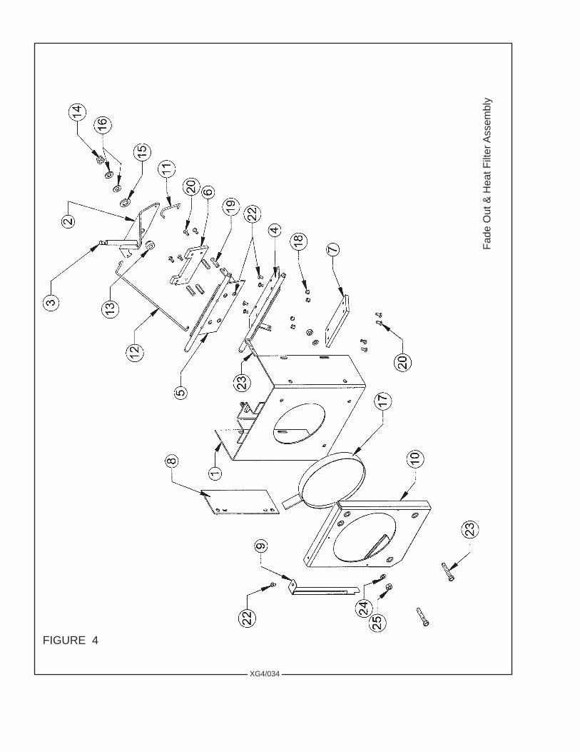
FIGURE 4
Fade
Out
& H
eat F
ilter
Ass
embl
y
XG4/034

Item PartNo. Description 1 72-00212 Fade Out Housing, Welded Assembly 2 72-00262 Bell Crank, Fade Out Dousers 3 51155000 Control Lever, Fade Out - 4257102 Flatwasher, 1/4"SAE - 4258001 Hexnut, 1/4-20 4 72-00268 Lower Douser Blade Assembly 5 72-00265 Upper Douser Blade Assembly 6 72-00272 Heat Shield, Upper Blade 7 72-00271 Heat Shield, Lower Blade 8 83351000 Pivot Adjusting Plate, Douser Blades - 4100503 Mounting Screw, 10-32 x 1/2" 9 24332000 Cover Shield, Heat Filter 10 81847000 Heat Filter Holder, Welded Assembly 11 72-00273 Pull Rod, Short 12 72-00274 Pull Rod, Long - 01704000 Hitch Pin, Pull Rods (not shown; 4 req’d.) 13 51153000 Spacer Bushing 14 4318004 Lock Nut, 5/16-18 Hex 15 4507106 Washer, 1/2"Brass 16 4317102 Washer, 5/16" SAE (2 req’d.) 17 72-00504 Heat Filter & Ring Assembly 18 41-98003 Stand-Off, 1/4" Hex (4 req’d.) 19 51-56016 Stand-Off, 7/8" (4 req’d.) 20 4080375 Mounting Screw, 8-32 x 3/8"PanHead 22 4080250 Mounting Screw, 8-32 x 1/4"PanHead 23 4251500 Mounting Screw, 1/4-20 x 1-1/2" Hex Head (3 req’d.) 24 4257001 Lockwasher, 1/4" 25 4258001 Hexnut, 1/4-20
PARTS LISTFigure4
XG4/035

FIGURE 5A
Col
or B
oom
eran
g A
ssem
bly
No.
72-
0026
4
XG4/036

PARTS LISTFigure5A
XG4/037
Item PartNo. Description 1 72-00196 Bottom Plate 2 72-00195 Side Plate (2 req’d.) 3 72-00186 Pivot Rod 4 72-00176 Bronze Bearing (7 req’d.) 5 72-00181 Color Holder (6 req’d.) 6 51396000 Color Holder Catch Hook (6 req’d.) 7 72-00260 Retainer Clip (18 req’d.) 8 4040252 Screw, 4-40 x 1/4"SocketHead 9 4080250 Screw, 8-32 x 1/4"PanHead 10 4080255 Screw, 8-32 x 1/4"FlatHead 11 72-00177 Stop Plate 12 72-00194 Color Arm Catch Plate 13 72-00180 Color Arm, 0° (2 req’d.) 14 72-00183 Color Arm Release 15 72-00185 Spring Pivot Rod 16 72-00179 Color Arm, 10° (2 req’d.) 17 72-00178 Color Arm, 20° (2 req’d.) 18 72-00184 Color Arm, 30° 19 4060500 Screw, 6-32 x 1/2"PanHead 20 72-00259 Release Arm 21 71-98011 Dichroic Filter, Flame Red 22 71-98014 Dichroic Filter, Lavender 23 71-98012 Dichroic Filter, Wheat Yellow 24 71-98012 Dichroic Filter, Jade Green 25 71-98010 Dichroic Filter, Navy Blue 26 71-98009 Dichroic Filter, Magenta Purple 27 4100623 Screw, 10-32 x 5/8"FlatHead 28 51-58018 Expansion Spring (7 req’d.) 29 21-58011 Expansion Spring 30 72-00657 Captive Screw 31 4257106 Seal Washer, Neoprene (as req’d.) 32 4100252 Set Screw, 10-32 x 1/4" 33 4060256 Set Screw, 6-32 x 1/4" 34 21-37033 Roll Pin, 1/8” Dia. x 5/8" 35 51505000 Bumper Pad (NOTE: Cut to fit) 36 82-20385 Spring Stud, Threaded 4-40
Additional 50mm dichroic color filters available through most theatrical supply dealers.

FIGURE 5B
Color Boomerang Assembly No. 72-00709
XG4/038

PARTS LISTFigure5B
Item PartNo. Description 1 72-00710 Shroud Assembly 2 72-00714 Pivot Shaft 3 72-00713 Bearing Block (7 req’d.) 4 51396000 Color Holder Catch Hook (6 req’d.) 5 72-00715 Lock & Release Lever 6 72-00716 Lock/Release Lever Shaft 7 72-00721 Color Arm Assembly (6 req’d.) 8 71-58003 Rubber Bumper (6 req’d.) 9 72-00717 Gel Ring, 13½" Diameter; Welded Assembly (6 req’d.) 10 4257102 Flatwasher, 1/4" SAE (2 req’d.) 11 4250504 Screw, 1/4-20 x 1/2" Button Head (16 req’d.) 12 4080183 Screw, 8-32 x 3/16" (12 req’d.) 13 4268003 Acorn Nut, 1/4-28 14 2468006 Jam Nut, 1/4-28 Hex 15 01704000 Hitch Pin (3 req’d.) 16 71-58004 Torsion Spring
NOTSHOWN
71-34001 Magnetic Label, Dry-Erase 31-98642 Lanyard, Safety Cable
XG4/039

FIGURE 6
Iris, Chopper & Aperture Assembly
XG4/040

PARTS LISTFigure 6
Item PartNo. Description 1 72-00201 Iris Mount 2 72-00263 Iris Bell Crank 3 24374000 Iris 4 72-00075 Iris Linkage 5 72-00199 Iris Clamp (2 req’d.) 6 48402000 Iris Lever - 4257002 Flatwasher, 1/4"SAE - 4258001 Hexnut, 1/4-20 7 72-00200 Iris Back Plate 8 47972000 Upper Chopper Blade Assembly 9 47973000 Lower Chopper Blade Assembly 10 72-00197 Guide Plate (2 req’d.) 11 4507106 Washer, 1/2"Brass 12 51153000 Spacer Bushing, Chopper Blade 13 51520000 Bell Crank, Chopper Blades 14 51452000 Chopper Control Lever 15 72-00198 Gobo Holder 16 81432000 Shoulder Screw, 10-24 17 21-37011 Roll Pin, 3/32" x 9/16" 18 25017000 Shim Spacer 19 4251002 Screw, 1/4-20 x 1"SocketHead 20 4257102 Flatwasher, 1/4" SAE (2 req’d.) 21 51-35013 Stop Nut 22 4060250 Screw, 6-32 x 1/4" Pan Head (2 req’d.) 23 4080501 Screw, 8-32 x 1/2" Flat Head (2 req’d.) 24 4250251 Set Screw, 1/4-20 x 1/4" (2 req’d.) 25 72-00275 Chopper Blade Pull Rod, Short 26 72-00276 Chopper Blade Pull Rod, Long 27 4080181 Screw, 8-32 x 3/16" Pan Head (2 req’d.) 28 4080310 Screw, 8-32 x 5/16" Pan Head (4 req’d.) 29 4060252 Screw, 6-32 x 1/4" Flat Head (3 req’d.) 30 4258007 Stop Nut 31 4311251 Screw, 5-16-18 x 1-1/4"FlatHead 32 4317102 Flatwasher, 5/16"SAE 33 4318004 Hex Nut, 5-16-18 FlexLock 34 4080250 Screw, 8-32 x 1/4" Pan Head (3 req’d.)
XG4/041

FIGURE 7
XG4/042
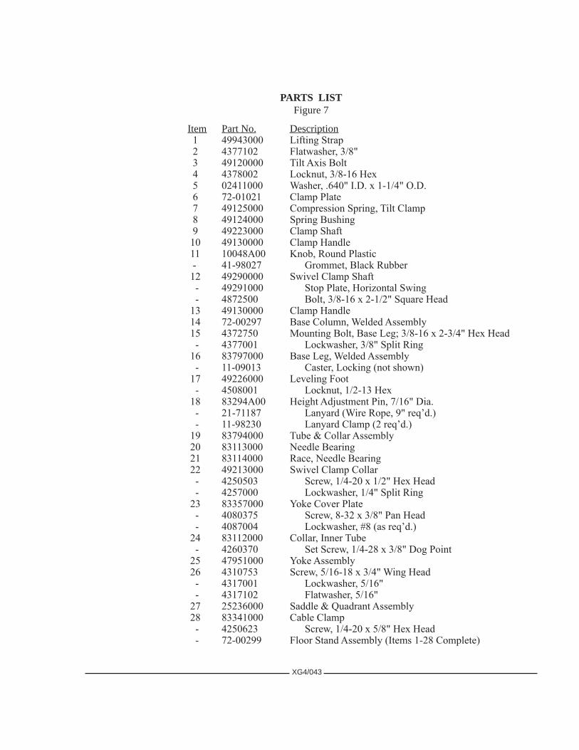
PARTS LISTFigure7
XG4/043
Item PartNo. Description 1 49943000 Lifting Strap 2 4377102 Flatwasher, 3/8" 3 49120000 Tilt Axis Bolt 4 4378002 Locknut, 3/8-16 Hex 5 02411000 Washer, .640" I.D. x 1-1/4" O.D. 6 72-01021 Clamp Plate 7 49125000 Compression Spring, Tilt Clamp 8 49124000 Spring Bushing 9 49223000 Clamp Shaft 10 49130000 Clamp Handle 11 10048A00 Knob, Round Plastic - 41-98027 Grommet, Black Rubber 12 49290000 Swivel Clamp Shaft - 49291000 Stop Plate, Horizontal Swing - 4872500 Bolt, 3/8-16 x 2-1/2" Square Head 13 49130000 Clamp Handle 14 72-00297 Base Column, Welded Assembly 15 4372750 Mounting Bolt, Base Leg; 3/8-16 x 2-3/4" Hex Head - 4377001 Lockwasher, 3/8" Split Ring 16 83797000 Base Leg, Welded Assembly - 11-09013 Caster, Locking (not shown) 17 49226000 Leveling Foot - 4508001 Locknut, 1/2-13 Hex 18 83294A00 Height Adjustment Pin, 7/16" Dia. - 21-71187 Lanyard (Wire Rope, 9" req’d.) - 11-98230 Lanyard Clamp (2 req’d.) 19 83794000 Tube & Collar Assembly 20 83113000 Needle Bearing 21 83114000 Race, Needle Bearing 22 49213000 Swivel Clamp Collar - 4250503 Screw, 1/4-20 x 1/2" Hex Head - 4257000 Lockwasher, 1/4" Split Ring 23 83357000 Yoke Cover Plate - 4080375 Screw, 8-32 x 3/8" Pan Head - 4087004 Lockwasher, #8 (as req’d.) 24 83112000 Collar, Inner Tube - 4260370 Set Screw, 1/4-28 x 3/8" Dog Point 25 47951000 Yoke Assembly 26 4310753 Screw, 5/16-18 x 3/4" Wing Head - 4317001 Lockwasher, 5/16" - 4317102 Flatwasher, 5/16" 27 25236000 Saddle & Quadrant Assembly 28 83341000 Cable Clamp - 4250623 Screw, 1/4-20 x 5/8" Hex Head - 72-00299 Floor Stand Assembly (Items 1-28 Complete)

FIGURE 8
LAMPHOUSECABLEASSEMBLYPart No. 72-00251
POWERSUPPLYCABLEASSEMBLYPart No.62-70025
See Page XG4/004 for Connector Pinout
XG4/044

