x-rite 810 transmission/reflection color...
TRANSCRIPT

X - R I T E 8 1 0 T R A N S M I S S I O N / R E F L E C T I O N C O L O R
P H O T O G R A P H I C D E N S I T O M E T E R
Operator’s Manual
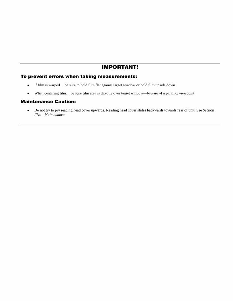
IMPORTANT!
To prevent errors when taking measurements:
• If film is warped… be sure to hold film flat against target window or hold film upside down.
• When centering film… be sure film area is directly over target window—beware of a parallax viewpoint.
Maintenance Caution:
• Do not try to pry reading head cover upwards. Reading head cover slides backwards towards rear of unit. See Section Five—Maintenance.

i
CAUTION: For continued protection against fire, replace only with same type fuse.
ADVERTENCIA: Para evitar el peligro de incendio en el caso de funcionamiento defectuoso del fusible, es preciso reemplazarlo con un fusible del mismo tipo.
AVVERTIMENTO: Per evitare il pericolo di un incendio nel caso di funzionamento difettoso del fusibile, rimpiazzarlo solamente con un fusibile dello stesso tipo.
VORSICHT: Für fotgesetzten Schutz gegen Feuer, ersetzen Sie die Sicherung nur mit einer vom gleichen Typ.
ATTENTION: Pour une défense continue contre le feu, remplacez le fusible seulement avec tel du même type.
NOTE: Shielded interface cables must be used in order to maintain compliance with the desired FCC or European emission requirements.
CAUTION: To prevent electrical shock, DO NOT remove cover. No user serviceable parts inside. Refer servicing to qualified service personnel.
ADVERTENCIA: Para evitar un choque eléctrico, NO QUITE el recubrimiento del aparato. No hay ninguno componente reparable de usuario, dentro del aparato. Consulte un técnico calificado para servicio o arreglo.
AVVERTIMENTO: Per evitare una scossa elettrica, non staccare la coperta del apparecchio. C’è nessuno componenti riparabili d’utente, interno del apparecchio. Consultare un tecnico qualificato per servizio o manutenzione.
VORSICHT: Um einen elektrischen Stromschlag zu verhindern, darf diese Abdeckung nicht entfernt werden. Es sind keine vom Benutzer zu wartenden Teile enthalten. Notwendige Reparaturen sollen nur durch autorisiertes Fachpersonnal ausgeführt werden.
ATTENTION: Pour prévenir un choc électrique, n’enlevez pas cette couverture. Il ne contient aucune pièce réparable. La réparation ne doit être fait que du personnel compétent.

ii
FCC This equipment has been tested and found to comply with the limits for a Class A digital device, pursuant to Part 15 of the FCC Rules. These limits are designed to provide reasonable protection against harmful interference when the equipment is operated in a commercial environment. This equipment generates, uses, and can radiate radio frequency energy and, if not installed and used in accordance with the instruction manual, may cause harmful interference to radio communications. Operation of this equipment in a residential area is likely to cause harmful interference in which case the user will be required to correct the interference at his own expense.
Canada This Class A digital apparatus meets all requirements of the Canadian Interference-Causing Equipment Regulations. Cet appareil numérique de la classe A respecte toutes les exigences du Règlement sur le matériel brouilleur du Canada.

iii
CE DECLARATION Manufacturer's Name: X-Rite, Incorporated Manufacturer's Address: 3100 44th Street, S.W. Grandville, Michigan 49418 U.S.A. Model Name: Densitometer Model No.: 810, 811 Directive(s) Conformance: EMC 89/336/EEC LVD 73/23/EEC
iv
Dear Customer:
Congratulations! We at X-Rite are proud to present you with the X-Rite 810 Color Transmission/Reflection Densitometer. This instrument represents the very latest in microprocessors, integrated circuits, and display technology. As a result, your 810 is a rugged and reliable instrument whose performance and design exhibit the qualities of a finely engineered laboratory instrument.
To fully appreciate and protect your instrument, we suggest that you take several minutes to read this manual. As always, X-Rite stands behind your 810 with a full one-year limited warranty and a dedicated service organization. If the need arises, please don’t hesitate to call on us.
Thank you for your trust and confidence.
X-Rite, Incorporated
v
I N T R O D U C T I O N
Proprietary Notice
The information contained in this manual is derived from patent and proprietary data from X-Rite, Incorporated. This manual has been prepared solely for the purpose of assisting operation and maintenance personnel in their use of the X-Rite 810.
The contents of this manual are the property of X-Rite, Incorporated and are copyrighted. Any reproduction in whole or part is strictly prohibited. Publication of this information does not imply any rights to reproduce it or use it for any purpose other than installing, operating, or maintaining the equipment described herein.
This instrument is covered by the following U.S. and foreign patents: U.S. Patent #4,080,075, and other patents pending.
Copyright © 1985, 1997 by X-Rite, Incorporated. “ALL RIGHTS RESERVED”

vi
Limited Warranty
X-Rite, Incorporated warrants each instrument manufactured by them to be free of defects in material and workmanship for a period of 12 months. THERE ARE NO WARRANTIES OF MERCHANTABILITY OR FITNESS. THIS WARRANTY OBLIGATION IS LIMITED TO SERVICING THE UNIT RETURNED TO THE FACTORY FOR THAT PURPOSE AND EXCLUDES ALL LAMPS. The instrument shall be returned with transportation charges prepaid. If the fault has been caused by misuse or abnormal operating conditions, repairs will be billed at a nominal cost. In this case, an estimate will be submitted before work is started, if requested.
A Warranty Registration Card is enclosed with each instrument. The purchaser should fill in the card completely and return it to X-Rite, Incorporated postmarked no later than ten (10) days from the date of receipt. This card registers your system with us for warranty coverage. Once your unit is registered, we are able to maintain a file to help expedite service in case it is needed. Always include serial number and place of purchase in any correspondence concerning your instrument. The serial number is located at the rear of the instrument.
This agreement shall be interpreted in accordance with the laws of the State of Michigan and jurisdiction and venue shall lie with the courts of Michigan as selected by X-Rite, Incorporated.

vii
I N T R O D U C T I O N
Table of Contents
SECTION ONE - GETTING STARTED
Unpacking Instructions 1-1
Voltage Selection 1-1
Applying Power 1-1
Display Angle Adjustment 1-2
Keyboard Description 1-2
Calibration Check 1-3 Transmission Check Step 1-3 Reflection Check Step 1-3
Setting Mode Functions 1-3 Baud Rate 1-4 Pin 5 (PN5) 1-4 Auto Identify (AID) 1-4 Remote Control Input (RCI) 1-4 Computer Output (COMP) 1-4 Decimal Point (DPT) 1-4 Language (LANG) 1-4
SECTION TWO - CALIBRATION
Transmission Calibration 2-1
Transmission Calibration Cal-Lo 2-2
Reflection Calibration 2-2
Reflection Calibration Cal-Lo 2-3
SECTION THREE - OPERATION
General 3-1
Selecting Transmission or Reflection 3-1
Selecting Density or HD-LD 3-1
Selecting Color 3-1

viii
Taking Measurements 3-2 Density Readings 3-2 HD-LD Readings 3-3
Help Messages 3-3 Activating Mode Help Messages 3-3
Error Messages 3-4
SECTION FOUR - SERIAL INTERFACE (RS-232)
Interconnect and Definition 4-1
Serial Output 4-1
Serial Input 4-1 Instruction Format 4-2 Address and Data Format 4-3
SECTION FIVE - MAINTENANCE
General 5-1
Troubleshooting Chart 5-2
Optics Cleaning 5-4 Transmission Optics 5-4 Reflection Optics 5-4
Reading Lamp Replacement 5-5
Opal Illumination Lamp Replacement 5-6
Transmission Optics Replacement 5-6
Reading Head Replacement 5-7
Fuse Replacement 5-8
SECTION SIX - SPECIFICATION
Instrument Specification 6-1

1-1
S E C T I O N O N E
Getting Started
Unpacking Instructions .............................1-1 Voltage Selection......................................1-1 Applying Power.........................................1-2 Display Angle Adjustment.........................1-2 Keyboard Description ...............................1-2 Calibration Check .....................................1-3 Setting Mode Functions............................1-3
UNPACKING INSTRUCTIONS Remove the instrument from the shipping carton. Inspect it for possible damage. If any damage is noted, contact the transportation company immediately. Do nothing more until the carrier’s agent has inspected the damage.
If damage is not evident, check the carton for the following items:
• Operation Manual • Registration Card (Please complete this and mail it within 10 days.) • X-Rite 810 Color Transmission/Reflection Densitometer and Line Cord • Calibration Step Tablet (part no. 810-68) • Calibration Check Plaque (part no. 302-12) • Spare Reading Lamp (part no. 820-52)
Your X-Rite 810 was packaged and shipped in a specially designed carton to assure against damage. If reshipment is necessary, the instrument should be repackaged in the original carton. If the original carton is not available, a new carton may be obtained from X-Rite, Incorporated.
VOLTAGE SELECTION 115VAC operation or 230VAC operation can be selected by sliding the voltage selection switch to the desired position, 115V or 230V. The voltage selection switch is located on the back panel of the instrument. See the 810 Back Panel diagram below.
810 BACK PANEL
1(on)
0(off)
115 230
Power Switch
Voltage Switch
Power Input

1-2
APPLYING POWER
NOTE: If the instrument has been stored in an abnormal (cold) environment, DO NOT apply power until the instrument reaches a normal environment temperature (10° to 30°C/50° to 86°F).
CAUTION: For safety and instrument stability, do not modify the line cord provided with the instrument. Connect the line cord to a grounded 3 wire receptacle.
Steps To apply power to the instrument, complete the following steps. If needed, refer to the 810 Back Panel diagram in the Voltage Selection section.
1. Plug the female end of the line cord into the Power Input (located on the back panel). Plug the other end of the line cord into a grounded wall outlet.
2. Set the Power Switch to 1 (on). 3. Upon power up, the instrument displays the current software datecode. (X-Rite 810 Vymdd;
y = year; m = month (hexadecimal); dd = day) 4. The instrument then performs a self test. If it passes, SELF-TEST = PASS is displayed. If it
doesn’t pass, an error message is displayed stating the error (see the Error Messages section). 5. After the instrument passes the self test, it automatically returns to the last density (or HD-
LD) function performed.
DISPLAY ANGLE ADJUSMENT This feature allows the user to set the viewing angle to specifically fit their individual line of sight. This is accomplished electronically in the display window. The Display Angle adjustment wheel is located on the left side panel of the instrument.
Steps To adjust the display angle, turn the Display Angle adjustment wheel either to the back (+) or to the front (-) of the instrument until the information in the display can be best seen at the operating line of sight.
KEYBOARD DESCRIPTION Below lists the instrument keys and their descriptions. For more information about a key’s function, refer to Section Three—Operation.
T/R selects the Transmission or Reflection. The T/R key toggles between Transmission and Reflection each time the key is pressed.
COLOR displays or changes which color(s) are displayed. All four colors are always measured, and the COLOR key selects which color(s) are displayed and printed. There are three different color options:
• Visual • Red, Green, Blue • Auto (automatic color select)
After a reading, use the COLOR key to view the values of the colors that were not originally selected.
HD-LD selects the High Density minus Low Density function. This function is used for finding the difference between successive pairs of density measurements.
CAL selects the Calibration. Calibration allows you to re-calibrate or quick Cal-Lo transmission and reflection. It also enables you to set up the mode functions. For more information, refer to the Calibration Check section and to Section Two—Calibration.

1-3
CALIBRATION CHECK To ensure accuracy, calibration should be checked before initial use and approximately once a month thereafter.
Transmission Check Steps: 1. Perform a Quick Cal-Lo calibration. (See Section Two—Calibration.) 2. Read the CAL HI step on your step tablet. The measurements must be within the following
values: • + .02 (0-3.0D) • + 1% (3.1D-3.5D) • + 3% (3.6D-4.0D)
3. If the densities are not within specification, re-calibrate the instrument by performing a full Transmission Calibration. . (See Section Two—Calibration.)
NOTES: Steps 1, 2, and 4 on your step tablet are used as a linearity check. Visual density can be displayed by sequencing through the color operations via the COLOR key. Temp 85° F, Rel. Hum. < 76%
Reflection Check Steps: The color names on the back of your check plaque are marked CYN, MAG, and YEL. They correlate to RED, GRN, BLU as follows:
• CYN = RED • MAG = GRN • YEL = BLU
1. Select R, G, B color operation. (See Section Three—Operation.) 2. Read the white spot on the check plaque. If the reading is not within .02D as specified for
Step 1 on the back of the check plaque, perform a Quick Cal-Lo calibration. (See Section Two—Calibration.)
3. Read the black spot on the check plaque. If reading is not within .02D as specified for Step 3 on the back of the check plaque, re-calibrate the instrument. (See Section Two—Calibration.)
NOTES: The gray spot (Step 2) on your check plaque is used as a linearity check. Visual density can be displayed by sequencing through the color operations via the COLOR key.
SETTING MODE FUNCTIONS There are six mode functions used in conjunction with the I/O port. For further explanation of the I/O port, see Section Four—Serial Interface (RS-232). The mode functions are contained in four mode pages:
Page # Mode Functions P1 Baud and PN5 P2 AID and RCI P3 Comp and DPT P4 LANG
The following are descriptions of the seven mode functions.
1-4
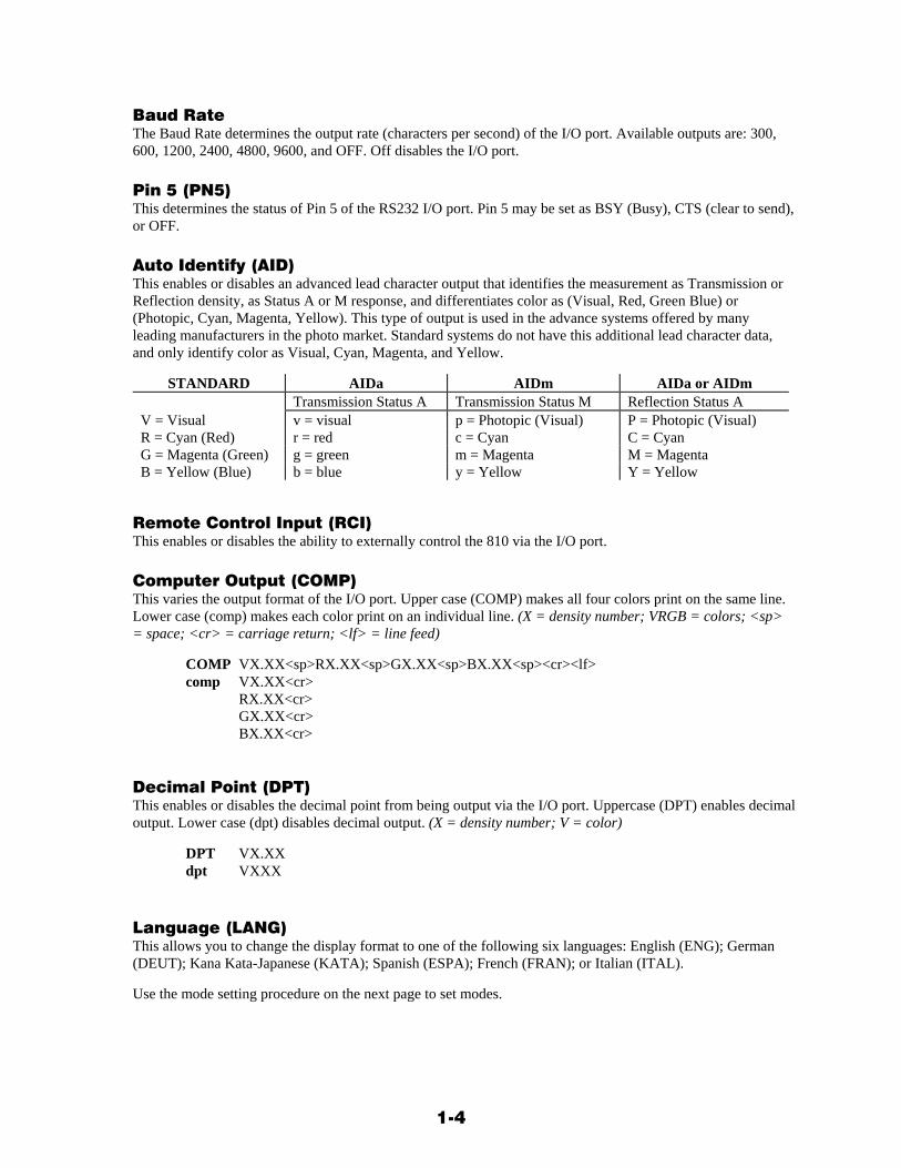
Baud Rate The Baud Rate determines the output rate (characters per second) of the I/O port. Available outputs are: 300, 600, 1200, 2400, 4800, 9600, and OFF. Off disables the I/O port.
Pin 5 (PN5) This determines the status of Pin 5 of the RS232 I/O port. Pin 5 may be set as BSY (Busy), CTS (clear to send), or OFF.
Auto Identify (AID) This enables or disables an advanced lead character output that identifies the measurement as Transmission or Reflection density, as Status A or M response, and differentiates color as (Visual, Red, Green Blue) or (Photopic, Cyan, Magenta, Yellow). This type of output is used in the advance systems offered by many leading manufacturers in the photo market. Standard systems do not have this additional lead character data, and only identify color as Visual, Cyan, Magenta, and Yellow.
STANDARD AIDa AIDm AIDa or AIDm Transmission Status A Transmission Status M Reflection Status A V = Visual v = visual p = Photopic (Visual) P = Photopic (Visual) R = Cyan (Red) r = red c = Cyan C = Cyan G = Magenta (Green) g = green m = Magenta M = Magenta B = Yellow (Blue) b = blue y = Yellow Y = Yellow
Remote Control Input (RCI) This enables or disables the ability to externally control the 810 via the I/O port.
Computer Output (COMP) This varies the output format of the I/O port. Upper case (COMP) makes all four colors print on the same line. Lower case (comp) makes each color print on an individual line. (X = density number; VRGB = colors; <sp> = space; <cr> = carriage return; <lf> = line feed)
COMP VX.XX<sp>RX.XX<sp>GX.XX<sp>BX.XX<sp><cr><lf> comp VX.XX<cr> RX.XX<cr> GX.XX<cr> BX.XX<cr>
Decimal Point (DPT) This enables or disables the decimal point from being output via the I/O port. Uppercase (DPT) enables decimal output. Lower case (dpt) disables decimal output. (X = density number; V = color)
DPT VX.XX dpt VXXX
Language (LANG) This allows you to change the display format to one of the following six languages: English (ENG); German (DEUT); Kana Kata-Japanese (KATA); Spanish (ESPA); French (FRAN); or Italian (ITAL).
Use the mode setting procedure on the next page to set modes.

1-5
KEYBOARD DISPLAY
1. Press [CAL] Calibration NO YES
2. Press [HD-LD] (NO) Set modes NO YES
3. Press [CAL] (YES) p1 BAUD NO YES
4. Press [COLOR] p1 300 PN5 exit Present baud rate is displayed. Thereafter, each depression sequentially changes the baud rate as follows: 300, 600, 1200, 2400, 4800, 9600, OFF. (OFF disables the I/O port)
- Press [HD-LD] Present status of Pin 5 of RS232 I/O is displayed. Thereafter, each depression sequentially changes the status of Pin 5 as follows: BSY (Busy), CTS (clear to send), OFF (makes I/O independent of Pin 5 status.
- Press [T/R] p2 AID RCI exit Each depression sequentially select mode pages 1 through 4.
5. Press [COLOR] Each depression sequentially pages through aid (OFF), AIDm, Aida.
- Press [HD-LD] RCI turns on/off with each depression. RCI = ON, rci = OFF.
- Press [T/R] p3 COMP DPT exit Page 3 is selected.
6. Press [COLOR] Print format varies with each depression. COMP = one line print. comp = multiple line print.
- Press [HD-LD] Decimal point turns on/off with each depression. DPT = ON, dpt = OFF
- Press [CAL] Ends mode entry procedure and returns you back to normal operation.
- Press T/R p4 LANG exit Page 4 is selected.
7. Press [COLOR] Language format changes with each depression. Selections are: English (ENG), German (DEUT), Kana Kata-Japanese (KATA), Spanish (ESPA), French (FRAN), and Italian (ITAL)
- Press [CAL] Ends mode entry procedure and returns you back to normal operation.

1-6
2-1
S E C T I O N T W O
Calibration
Frequency of Calibration ..........................2-1 Transmission Calibration..........................2-1 Transmission Quick Cal-Lo ......................2-2 Reflection Calibration ...............................2-2 Reflection Quick Cal-Lo............................2-3
The X-Rite 810 is designed for long life and extremely stable readings. To follow good quality control practice, calibration should be checked periodically to verify measurement accuracy and proper operation of the instrument.
To verify calibration, a calibration step tablet has been provided for transmission operation and a calibrated ceramic check plaque for reflection operation. The transmission step tablet has a four step gray scale ranging from approximately .06D (step 1) to 4.0D (step 4). The reflection check plaque has three steps ranging from approximately .10D (step 1) to 2.0D (step 3). The values listed on the step tablet and check plaque are traceable to the National Bureau of Standards (NBS).
IMPORTANT: Both the step tablet and the check plaque must be kept free of smudge-marks and dust.
FREQUENCY OF CALIBRATION Under normal operating conditions, the instrument should be calibrated once a week or when instrument EPROM is changed.
TRANSMISSION CALIBRATION Use the calibration procedure below.
NOTE 1: Press [HD-LD] to increase and [CAL] to decrease density values.
NOTE 2: Press [COLOR] to proceed to next step.
NOTE 3: All density values are in reference to the CAL HI step on your step tablet.
1. Press [CAL] twice.
2. Press [HD-LD] or [CAL] to change VIS HI values. - Press [COLOR]
3. Press [HD-LD] or [CAL] to change RED HI values. - Press [COLOR]
4. Press [HD-LD] or [CAL] to change GRN HI values. - Press [COLOR]
5. Press [HD-LD] or [CAL] to change BLU HI values. - Press [COLOR]
6. Remove film from target area then hold [READ] depressed until data is displayed.
7. Center CAL HI step over target window then hold [READ] depressed until data is displayed.

2-2
TRANSMISSION QUICK CAL-LO Quick zero provides you with a quick and easy means of reestablishing zero (Calibration Low). This is needed because calibration low may drift over a period of time.
1. Select R, G, B color operation using the [COLOR] key. See Section 3.
2. Remove film from target window.
3. Press and hold [READ] button.
4. Momentarily press [CAL].
5. Release [READ] button after one second.
REFLECTION CALIBRATION Use the calibration procedure below.
NOTE 1: Press [HD-LD] to increase and [CAL] to decrease density values.
NOTE 2: Press [COLOR] to proceed to next step.
NOTE 3: Low density values are in reference to step 1 (white spot) and High density values to step 3 (black spot) on your plaque.
NOTE 4: Red = CYN, Grn = MAG, Blu = YEL on back of check plaque.
1. Press [CAL] twice.
2. Press [HD-LD] or [CAL] to change VIS low values. - Press [COLOR]
3. Press [HD-LD] or [CAL] to change RED low values. - Press [COLOR]
4. Press [HD-LD] or [CAL] to change GRN low values. - Press [COLOR]
5. Press [HD-LD] or [CAL] to change BLU low values. - Press [COLOR]
6. Press [HD-LD] or [CAL] to change VIS hi values. - Press [COLOR]
7. Press [HD-LD] or [CAL] to change RED hi values. - Press [COLOR]
8. Press [HD-LD] or [CAL] to change GRN hi values. - Press [COLOR]
9. Press [HD-LD] or [CAL] to change BLU hi values. - Press [COLOR]
10. Center White Spot over target window then hold [READ] depressed until data is displayed.
11. Center Black Spot over target window then hold [READ] depressed until data is displayed.
2-3
REFLECTION QUICK CAL-LO Quick zero provides you with a quick and easy means of reestablishing zero (Calibration Low). This is needed because calibration low may drift over a period of time.
1. Select R, G, B color operation using the [COLOR] key. See Section 3.
2. Center White spot of check plaque over target window.
3. Press and hold [READ] button.
4. Momentarily press [CAL].
5. Release [READ] button after one second.

2-4
3-1
S E C T I O N T H R E E
Operation
General .....................................................3-1 Selecting Transmission or Reflection .......3-1 Selecting Density or HD-LD .....................3-1 Selecting Color .........................................3-1 Taking Measurements ..............................3-2 Help Messages.........................................3-3 Error Messages ........................................3-4
GENERAL The X-Rite 810 was designed specifically for the photographic market. It will quickly and easily provide the finest quality control for all of your film processing needs. And, to satisfy the industry’s rigid quality standards, we’ve built the 810 to deliver the optimum in measuring accuracy.
Due to X-Rite’s electronic filter selection, selecting a color is as easy as pressing a button. The 810 provides Visual, or Red, Green, Blue, or Auto (automatic color selection) color measurement.
Being operator conscientious, the 810 provides you with display angle adjustment, simultaneous measurement of red, green, and blue, and a dot matrix alphanumeric LCD display. The LCD display exhibits prompt, help, and error messages.
Transmission and Reflection densitometry are alternately selected by pressing of the [T/R] key. The 810 also features High Density-Low Density, which is activated by pressing the [HD-LD] key.
NOTE: To extend the life of the read lamp, it is recommended that the instrument is turned off at the end of the day, or when not in use for an extended period of time. Warm up time in a stable environment is two minutes.
SELECTING TRANSMISSION OR REFLECTION Transmission or Reflection are alternately selected by pressing the [T/R] key. The display differentiates between Transmission and Reflection via the first digit on the left. T indicates Transmission and R indicates Reflection.
SELECTING DENSITY OR HD-LD Density and HD-LD are alternately selected by pressing the [HD-LD] key. The display differentiates between normal density and HD-LD measurements by displaying HL above the decimal point(s). Upon first entering HD-LD, READ HDLD Hi is displayed.
SELECTING COLOR The three different color operations (Visual, or Red, Green, Blue, or Auto) are sequentially selected by pressing the COLOR key.

3-2
TAKING MEASUREMENTS Transmission and Reflection readings are performed in the same manner.
Steps To take a measurement, complete the following steps.
1. Select the desired function and color. 2. Center the area to be measured over the target window. 3. Lower the reading head by pressing the READ button. 4. Hold the READ button down until the reading in the display is stable.
NOTE: A circular groove located on the light table is provided for holding disc. type film. Simply position the disc. into the groove and turn as desired.
The data that is displayed, and the procedure to follow for Density and HD-LD measurements are discussed in the following sub-sections.
♦ Density Readings Each time a measurement is taken, all four colors (visual, red, green, and blue) are read. The active color operation only determines which data is displayed. Therefore, if you are in Red, Grn, Blu operation and you want to look at Visual data, simply cycle through the color operations via the COLOR key until Vis is reached. Record the necessary data, then return back to normal operation.
Below illustrates the various displays for the three color operations.
VISUAL VISUAL V = X.XX
During Cycle Through During Measurement
RED, GRN, BLU RED GRN BLU X.XX X.XX X.XX
During Cycle Through During Measurement
AUTO AUTO X.XX
During Cycle Through Red
During Measurement
X.XX
Grn
During Measurement
X.XX
Blu
During Measurement
X.XX X.XX X.XX
All three
Auto can be displayed four different ways. Normally, only the most dominant color displays. If there is not a dominant color, all three colors are displayed.
3-3
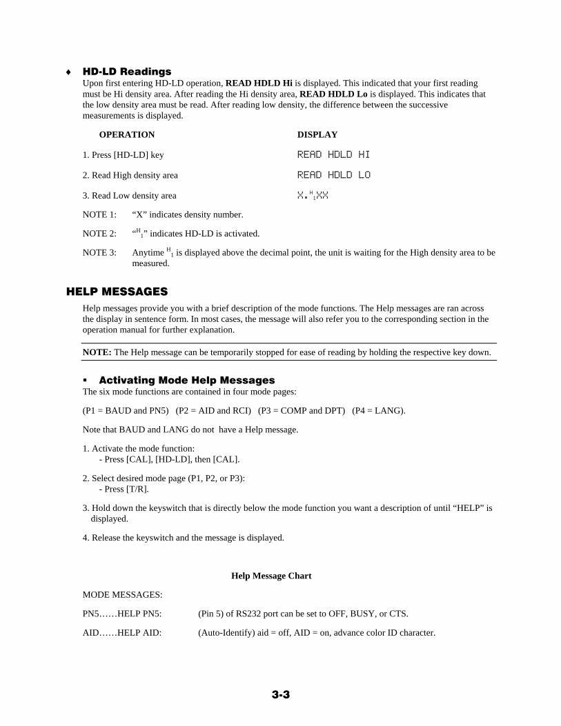
♦ HD-LD Readings Upon first entering HD-LD operation, READ HDLD Hi is displayed. This indicated that your first reading must be Hi density area. After reading the Hi density area, READ HDLD Lo is displayed. This indicates that the low density area must be read. After reading low density, the difference between the successive measurements is displayed.
OPERATION DISPLAY
1. Press [HD-LD] key READ HDLD HI
2. Read High density area READ HDLD LO
3. Read Low density area X.H1XX
NOTE 1: “X” indicates density number.
NOTE 2: “H1” indicates HD-LD is activated.
NOTE 3: Anytime H1 is displayed above the decimal point, the unit is waiting for the High density area to be measured.
HELP MESSAGES Help messages provide you with a brief description of the mode functions. The Help messages are ran across the display in sentence form. In most cases, the message will also refer you to the corresponding section in the operation manual for further explanation.
NOTE: The Help message can be temporarily stopped for ease of reading by holding the respective key down.
Activating Mode Help Messages The six mode functions are contained in four mode pages:
(P1 = BAUD and PN5) (P2 = AID and RCI) (P3 = COMP and DPT) (P4 = LANG).
Note that BAUD and LANG do not have a Help message.
1. Activate the mode function: - Press [CAL], [HD-LD], then [CAL].
2. Select desired mode page (P1, P2, or P3): - Press [T/R].
3. Hold down the keyswitch that is directly below the mode function you want a description of until “HELP” is displayed.
4. Release the keyswitch and the message is displayed.
Help Message Chart
MODE MESSAGES:
PN5……HELP PN5: (Pin 5) of RS232 port can be set to OFF, BUSY, or CTS.
AID……HELP AID: (Auto-Identify) aid = off, AID = on, advance color ID character.
3-4
RCI……HELP RCI: (Remote Control Interface) rci = off, RCI = on, enable input of serial command.
COMP...HELP COMP: (COMPuter) COMP = CR-LF after last color, comp = CR after each color.
DPT……HELP DPT: (Decimal Point) dpt = off, DPT = on.
PAGE….HELP P#: (Page) accesses next MODE page.
EXIT…..HELP EXIT: Ends SET MODES procedure.
ERROR MESSAGES Error messages are displayed to let you know a problem has occurred. Error messages can be displayed during power up or during operation. Below is a list of possible error messages and explanations.
DURING POWER UP
Message Reason ERROR #1 - MEMTEST Main P.C.B. bad. ERROR #2 - MEMTEST Main P.C.B. bad. ERROR #3 - LMPTEST Lamp, Trans. P.C.B., or Trans. Optics bad. ERROR #4 - TMPTEST Temp. sensor or Trans. P.C.B. bad. ERROR #5 - STK KEY Shorted keyswitch. ERROR #6 - READLMP Read lamp, Reflection P.C.B. bad.
DURING OPERATION
Message Reason MEM FAIL ADDR- Main P.C.B. bad. INVALID READING! Operator did not hold down READ switch long enough. NEED REFL. STAND! Check plaque was not used during reflection calibration.
4-1
S E C T I O N F O U R
Serial Interface (RS232)
Interconnect and Definition.......................4-1 Serial Output.............................................4-1 Serial Input................................................4-1
INTERCONNECT AND DEFINITION The 25-pin connector used for serial input/output is a DP25S type. Below is a connection diagram.
Pin 2 Transmitted Data - Data being transmitted from the densitometer with the parameters (baud rate, Format) set by the densitometer.
Pin 3 Received Data - Data received by the densitometer from an outside source using the same parameters as the densitometer.
Pin 4 RTS (Request to Send) - Logic 0 only. Pin 5 CTS (Clear to Send) - Logic 0 active. Pin 5 BSY (Busy) - Logic 1 active. Pin 6 DSR (Data Set Ready) - Logic 0 only. Pin 20 DTR (Data Terminal Ready) - Logic 0 only.
NOTE: Logic 1 = +.8VDC to -25VDC; Logic 0 = +2.25VDC to +25VDC
A typical interconnection (in simplest form) between the densitometer and a computer is shown below.
Densitometer Computer
2 3 3 2 7 7
SERIAL DATA INPUT NOTE: Data shall be transmitted by an outside source (computer) with one start bit (Logic 0), 7 bits of ASCII, one parity bit (ignored), then one or two stop bits (Logic 1).
SERIAL OUTPUT The data format that is output from the densitometer is determined by the six mode functions. See Section One—Getting Started.
SERIAL OUTPUT NOTE: Data shall be transmitted by the densitometer with one start bit (Logic 0), 7 bits of ASCII, one parity bit (ignored), then one stop bit (Logic 1).
SERIAL INPUT Your 810 is equipped with an input which allows the 810 to be controlled or monitored remotely. Every function which can be performed at the keyboard (plus a few special functions not activated by the keyboard) can be activated via the serial input.
Basically, the remote control input (RCI) format consists of a series of characters (a command string) sent to the 810 in ASCII format with a carriage return or line feed (not both) at the end of each command string to act as a delimiter. The densitometer then acts on that command. The Serial Input Buffer of the 810, upon receiving its first command string character, generates a “Buffer Full” interrupt to the microprocessor.

4-2
The 810 Microprocessor then halts all normal operation and dedicates itself to receiving and responding to remote control command strings. Normal execution is resumed upon receiving a GO command via the serial input.
♦ Instruction Format In general, the format used for serial input is as follows:
1 2 3 4 5 6 DATA ADDRESS ACTION CODE <LF> <G> <LF>
1 DATA - is a two character hexadecimal code (in ASCII) which is written to the control register that is being addressed; and is used during a Write Action only.
2 ADDRESS - is a one to three character hexadecimal code (in ASCII) that selects the memory location which will be acted upon.
3 ACTION CODE - is a single character which is used to define the Remote Control Action as follows: NOTE: All Action Codes for the instrument must be sent in lowercase letters.
4 <LF> (Line Feed) is an ASCII Line Feed used as a delimiter and tells the instrument to perform the preceding command, and, unless that command was "G", wait for the next command. (Note: A "CR" can be sent instead of a "LF" if necessary.)
5 <G> (GO) is an ASCII character sent to the densitometer to release it to operate as instructed after the “LF” (or “CR”) is received. (Note: The reason for the GO command is that when the densitometer senses that data is being received on the serial input, it stops normal operation and only allows the serial input to modify or monitor keys and control registers until a “G” Action Code is given to return the densitometer to normal operation.
6 <LF> (Line Feed) is an ASCII Line Feed used as a delimiter and tells the instrument to perform the "G" command. (Note: A "CR" can be sent instead of a "LF" if necessary.)
Action Codes READ (R) is used to cause the 810 to serially output in ASCII format two hexadecimal characters
representing the binary data specified in the ADDRESS portion of the command string. WRITE (W) is used to cause the 810 to replace the contents of the microprocessor RAM location
designated in the ADDRESS portion of the command string with 8 bits of binary data represented by the two hexadecimal characters in the DATA.
KEY (K) is used to remotely press any of the four keys on the face of the 810. The ACTION CODE K is preceded by a 0, 1, 2, or 3 to indicate the T/R, COLOR, HD-LD, or CAL key respectively.
SWITCH 1, 2, 3, OR 4 (1, 2, 3 or 4) is used to turn ON or OFF certain special operational features. GO (G) is used to release the 810 from the remote control/monitor software to the normal
operation software from which it was interrupted by a serial input command. No DATA or ADDRESS is required with the G command.
STRING (S) is used to place the 810 Serial Input into a String Transfer Mode, where each character entering the Serial Input port after the execution of an S Action Code is transferred directly to the LCD display. The first character sent appears in character position NN of the LCD display where NN = the 2 ASCII hexadecimal ADDRESS characters sent just prior to the S Action Code. Each successive string character sent will appear directly to the right of the previous character. The String Transfer Mode is terminated when a carriage return (CR=ODH) is received.
4-3
TRANSMIT (X) is used to transmit the present contents (16 characters) of the display to the RS232 serial port.
VERSION (V) is used to transmit the first 16 characters that appear at power up, which contain the most current software date code.
♦ Address and Data Format The following is a list of the addresses and the keys or control registers at each of those addresses.
Address (Hex) Keys or Control Registers 26 Color 40 T/R key 41 Color key 42 HD-LD key 43 Cal key
The following is a list of the DATA BITS to be used with various Keys or Control Registers.
DATA BIT KEY OR CONTROL REGISTER
0 - F 0 - F
MSB LSB
X X X 0 VIS RED GRN BLUE Color
(CYN MAG YEL)
x = Don’t Care
Remote Control Switches and Selects (1, 2, 3, 4, or S is the Action Code and its prefix of ON, OFF, 0, 1, or 2 is used instead of an ADDRESS and DATA.)
ON1 Read + Light Source Turns on Light Source and forces a READ. OFF1 Read + Light Source Turns off Light Source and disables READ. ON2 Keys On Enables keys on the instrument to function. OFF2 Keys Off Disables all keys except the READ button. ON3 Display On Enables the display. OFF3 Display Off Disables writing of new information to the display. ON4 Transmit at EOC On Enables a transmit of data at the end of every A/D conversion. OFF4 Transmit at EOC Off Disables a transmit of data at the end of every A.D conversion.
Serial Input Notes Additionally, the following is required in order to use the serial input.
• The baud rate of the serial input must be the same as the densitometer uses for serial output. • Data shall be transmitted with one start bit (Logic 0) and one or two stop bits (Logic 1) added to the data
(7 bits of ASCII). The parity bit is set to zero. The logic 1 (marking) condition of the data signal is defined to be between 0 and -15V. The logic 0 (spacing) condition of the data signal is defined to be between 2.4 and +15V.
• Each KEY action to a Key Address must be followed by <G><LF> because the densitometer must process each key stroke one at a time.

4-4
• After each READ action the contents of the selected address are sent out of the serial output, most significant character first. Also, multiple READS do not require multiple <G><LF>s.
• The Remote Control Switches and Selects are not stored or maintained when power is turned off. The default condition at power up is as follows: OFF1; ON2; ON3; OFF4.
• Contact the factory if you have any questions.

5-1
S E C T I O N F I V E
Maintenance
General .....................................................5-1 Troubleshooting Chart ..............................5-2 Optics Cleaning ........................................5-4 Reading Lamp Replacement....................5-5 Opal Illumination Lamp Replacement ......5-6 Transmission Optics Replacement...........5-6 Reading Head Replacement ....................5-7 Fuse Replacement ...................................5-8
GENERAL The X-Rite 810 Densitometer is covered by a one-year limited warranty (excluding lamps) and should be referred to the factory or authorized service center for repair within this warranty period. Attempts to make repairs within in this time may void any warranty.
Always verify instrument calibration to assure proper instrument operation. Make sure all connections are properly made.
X-Rite provides a factory repair service to their customers. Because of the complexity of the circuitry, repairs should be referred to the factory or authorized service center.
As a routine maintenance procedure, replace the lamp after every 2500 hours of operation. This allows approximately one year of operation per lamp (based on an 8 hour shift). Failure to do so may cause erroneous readings.
♦ Cleaning Whenever required, the exterior of the instrument may be wiped clean with a cloth dampened in water or a mild cleaner.
5-2
TROUBLESHOOTING CHART IMPORTANT! Before proceeding with the following troubleshooting chart, check the following items:
• Make sure the instrument has been properly calibrated. • If a wrong reading problem exists, re-calibrate or Quick Cal-Lo the instrument and recheck the problem. • Always check to see if the read lamp is working. Problem Cause Solution
Display not working Display angle adjusted too low Display Cable loose/bad Display P.C.B. Ass’y Main P.C.B. Ass’y
Readjust display angle control Call Service Tech. Call Service Tech. Call Service Tech.
Read Lamp not working
Read Lamp open Read switch open Open connection in reading head Main P.C.B. Ass’y
Replace read lamp. Call Service Tech. Replace/repair reading head Call Service Tech.
Unit completely dead
Bad connection on AC line cord Main P.C.B. Ass’y
Call Service Tech. Call Service Tech.
Opal lamp not working
Lamp open Transmission P.C.B. Main P.C.B. Ass’y
Replace lamp. Call Service Tech. Call Service Tech.
Read lamp flickers during reading
Read switch dirty Lamp loose
Call Service Tech. Tighten Lamp
Segment or digit out in display
Display cable loose/bad Display P.C.B. Ass’y Main P.C.B. Ass’y
Call Service Tech. Call Service Tech. Call Service Tech.
Transmission readings incorrect
Not calibrated properly Transmission optics dirty/bad Read lamp weak Reading Head Ass’y Transmission P.C.B. Ass’y Main P.C.B. Ass’y
Check calibration and re-calibrate if necessary Clean or replace optics Replace or tighten lamp Replace reading head Call Service Tech. Call Service Tech.
Reflection readings incorrect
Not calibrated properly Optics dirty/bad Read lamp weak Reading Head Ass’y Main P.C.B. Ass’y
Check calibration and re-calibrate if necessary Clean or replace reading head Replace reading lamp Replace reading head Call Service Tech.
5-3
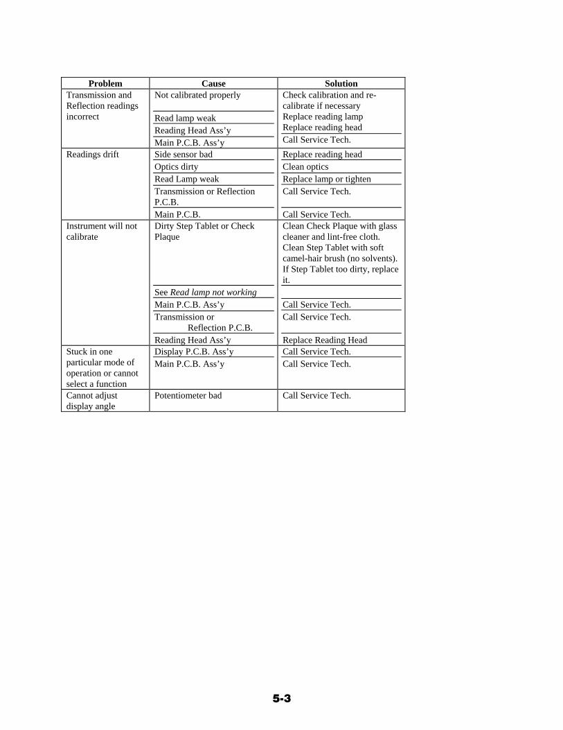
Problem Cause Solution
Transmission and Reflection readings incorrect
Not calibrated properly Read lamp weak Reading Head Ass’y Main P.C.B. Ass’y
Check calibration and re-calibrate if necessary Replace reading lamp Replace reading head Call Service Tech.
Readings drift Side sensor bad Optics dirty Read Lamp weak Transmission or Reflection P.C.B. Main P.C.B.
Replace reading head Clean optics Replace lamp or tighten Call Service Tech. Call Service Tech.
Instrument will not calibrate
Dirty Step Tablet or Check Plaque See Read lamp not working Main P.C.B. Ass’y Transmission or Reflection P.C.B. Reading Head Ass’y
Clean Check Plaque with glass cleaner and lint-free cloth. Clean Step Tablet with soft camel-hair brush (no solvents). If Step Tablet too dirty, replace it. Call Service Tech. Call Service Tech. Replace Reading Head
Stuck in one particular mode of operation or cannot select a function
Display P.C.B. Ass’y Main P.C.B. Ass’y
Call Service Tech. Call Service Tech.
Cannot adjust display angle
Potentiometer bad Call Service Tech.

5-4
OPTICS CLEANING
IMPORTANT! Unplug the line cord before servicing.
♦ Transmission Optics Clean the opal glass with a Q-Tip slightly moistened with glass cleaner or alcohol.
♦ Reflection Optics Remove dust and lint by lightly blowing compressed air into the nose cone opening in the reading head. To avoid contamination, turn the instrument on its side so the compressed air container remains upright.

5-5
READING LAMP REPLACEMENT
IMPORTANT! Unplug the line cord before servicing.
Steps To properly replace a reading lamp, complete the following steps.
1. Remove the read button by pulling upward. 2. Lift the back of the reading arm cover and slide it backwards along side channels toward the
back of the instrument. 3. Remove the actuator bar by lifting upwards. 4. Unplug connectors P19 and P17. 5. Unscrew the two screws on the read lamp assembly and remove the assembly. 6. Secure the new reading lamp assembly (part no. 820-52) in place with the two screws. 7. Reconnect connectors P19 and P17. 8. Install the actuator bar. 9. Slide the reading arm cover back into place. 10. Press the read button firmly onto the actuator bar. The bottom pegs of the read button fit into
the two holes in the actuator bar.
Note direction of arrow.
5-6
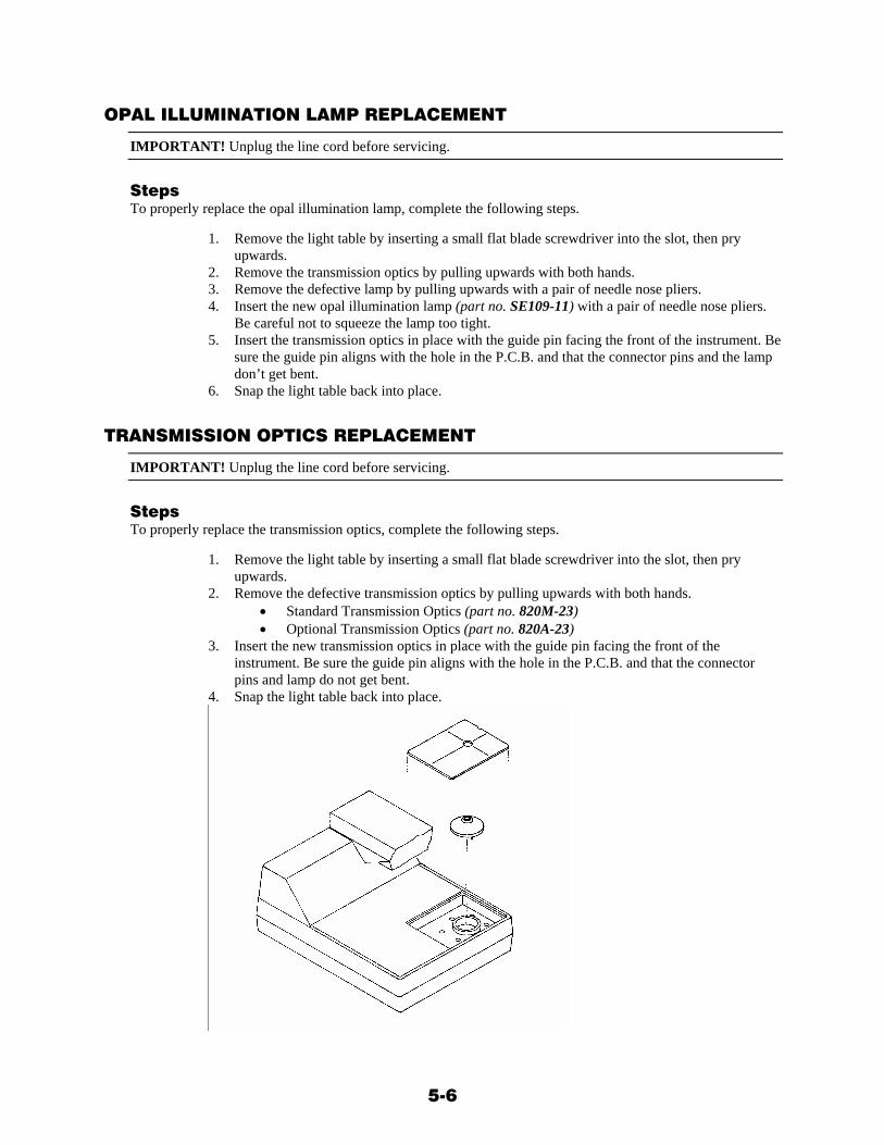
OPAL ILLUMINATION LAMP REPLACEMENT
IMPORTANT! Unplug the line cord before servicing.
Steps To properly replace the opal illumination lamp, complete the following steps.
1. Remove the light table by inserting a small flat blade screwdriver into the slot, then pry upwards.
2. Remove the transmission optics by pulling upwards with both hands. 3. Remove the defective lamp by pulling upwards with a pair of needle nose pliers. 4. Insert the new opal illumination lamp (part no. SE109-11) with a pair of needle nose pliers.
Be careful not to squeeze the lamp too tight. 5. Insert the transmission optics in place with the guide pin facing the front of the instrument. Be
sure the guide pin aligns with the hole in the P.C.B. and that the connector pins and the lamp don’t get bent.
6. Snap the light table back into place.
TRANSMISSION OPTICS REPLACEMENT
IMPORTANT! Unplug the line cord before servicing.
Steps To properly replace the transmission optics, complete the following steps.
1. Remove the light table by inserting a small flat blade screwdriver into the slot, then pry upwards.
2. Remove the defective transmission optics by pulling upwards with both hands. • Standard Transmission Optics (part no. 820M-23) • Optional Transmission Optics (part no. 820A-23)
3. Insert the new transmission optics in place with the guide pin facing the front of the instrument. Be sure the guide pin aligns with the hole in the P.C.B. and that the connector pins and lamp do not get bent.
4. Snap the light table back into place.

5-7
READING HEAD REPLACEMENT
IMPORTANT! Unplug the line cord before servicing.
Steps To properly replace the reading head, complete the following steps.
1. Remove the read button by pulling upward. 2. Lift the back of the reading arm cover and slide it backwards along side channels toward the
back of the instrument. 3. Remove the actuator bar by lifting upwards. 4. Unplug connector P18. 5. Hold the reading head from underneath the reading arm with your hand. 6. Pull out the reading head spring from each side of the reading head. 7. Lift and remove the reading head. 8. Slide connector P18 under the spring pivot. 9. Insert the new reading head (part no. 820A-35) into the opening of the reading arm. 10. Place the reading head spring into each side of the reading head. 11. Reconnect connector P18. 12. Install the actuator bar. 13. Slide the reading arm cover back into place. 14. Press the read button firmly onto the actuator bar. The bottom pegs of the read button fit into
the two holes in the actuator bar.
5-8
FUSE REPLACEMENT
NOTE: If your instrument has a replaceable fuse on the back panel, follow the steps below.
Fuse Part Numbers: SE24-0040 (115VAC operation) SE49-0020 (230VAC operation)
IMPORTANT! Unplug the line cord before servicing.
Steps To properly replace the fuse, complete the following steps.
1. Insert a flat-blade screwdriver into the slot of the fuse cap. 2. Push in and turn counterclockwise one-half turn until the fuse and fuse cap pop out. 3. Remove fuse from fuse cap and replace with same type fuse.
- 115VAC (1/4”D x 1-1/4”L, 400ma Slo-blo) - 230VAC (5mm D x 20mm L, 200ma Slo-blo)
4. Insert fuse and fuse cap into fuse holder. Push in and turn clockwise one-half turn until fuse cap locks.
FUSE REPLACEMENT ♦ Caution:
Fuses not intended to be user replaceable. Fuses are only to be replaced by a qualified service technician.
- Replace fuse with same type and rating. 3AG, 400ma Slo-Blo X-Rite part number: SE24-0040
6-1
S E C T I O N S I X
Specifications
INSTRUMENT SPECIFICATIONS
♦ Features • Density • Density Difference • Red, Green, Blue, or Visual Measurement • Simultaneous Color Measurement and
Display • Automatic Color Measurement • One Memory Location (Difference) • Spare Main Lamp • Printed Reflection Reference Standard • Normal Transmission Reference Standard • Status A Reflection, Status M Transmission • RS232/Technet Formatted Output Interface
♦ Options • Status A Transmission Optics (Plug-in) • Table Lamp Kit • Interface Cable (RS232/Technet)
♦ Reflection Specifications • Response........................ Status A • Measuring Range........... 0 - 2.5D • Accuracy........................ + .02D • Repeatability.................. + .01D • Zero Stability................. + .02D per 8 hours • Scale Factor Stability..... + 1% per year • Measuring Area ............. 4mm • Warm-up Time .............. 2 minutes
♦ Transmission Specifications • Response........................ Status M • Measuring Range........... 0 - 4.0D • Accuracy........................ + .02D (0-3.0D)
....................................... + 1% (3.1-3.5D)
....................................... + 3% (3.6-4.0D) • Repeatability.................. + .01D • Zero Stability................. + .02D per 8 hours • Scale Factor Stability..... + 1% per year • Measuring Area ............. 4mm • Warm-up Time .............. 2 minutes
♦ Operating Specifications
• Voltage ..........................90-120VAC.......................................180-240VAC
• Line Frequency ..............50-60Hz • Power.............................50VA Max. • Temperature...................10°-30°C; 50°-86°F • Relative Humidity..........< 76% • Weight ....................(actual) 11 lbs./5 kg.
................................(shipping) 13.25 lbs./6 kg. • Dimensions ....................5.88”H x 8.63”W
.......................................x 11.13”L
♦ Miscellaneous Specifications • Altitude ..........................2000 m • IEC 664..........................Pollution Degree 2 • Usage ............................. Indoor only • Installation Type ............Category II • Safety .............................UL3101-1 • FCC................................Part 15, Class A,
.......................................Digital Device • Industry Canada............. ICES-003 Issue 2,
.......................................Revision 1 • International
EMC EN50081-1:1992 ...........Class B Generic .......................................Emission Standard EN50082-1:1992 ...........Generic Immunity .......................................Standard Safety (Pending) ............ IEC 1010-1 .......................................First Edition with .......................................Amdts. No. 1 (1992), .......................................No. 2 (1995)
Specifications and appearance design subject to change for reasons of product improvement, reliability, and/or manufacturability without notice.

6-2


P/N 810-64 Rev. II-2/26/04
X-RITE WORLD HEADQUARTERS
Grandville, Michigan USA (616) 534-7663 (800) 248-9748 FAX (616) 534-8960
X-RITE LATIN AMERICA
Hollywood, Florida USA 954-927-4979 FAX 954-927-4979
X-RITE LTD. Poynton, Cheshire United Kingdom 44 (0) 1625 871100 FAX 44 (0) 1625 871444
X-RITE MÉDITERRANÉE
Massy, France 33 1-6953-6620 FAX 33 1-6953-0052 X-RITE IBÉRICA
Barcelona, Spain 34 93 567 70 73 FAX 34 93 567 70 78
X-RITE ITALY S.R.L. Origgio (VA), Italy (39) 02-967-34266 FAX (39) 02-967-30681
X-RITE GMBH Köln, Germany (49) 2203-91450 FAX (49) 2203-914519 Vyskov, Czech Republic (00) 420 517-320-331 FAX (00) 420 517-320-335
X-RITE INTERNATIONAL TRADING LIMITED
Shanghai, PR China 86-21-6427-2426 FAX 86-21-6427-5816
X-RITE ASIA PACIFIC LTD. Quarry Bay, Hong Kong (852) 2-568-6283 FAX (852) 2-885-8610 X-RITE K.K. Tokyo, Japan 81-3-5439-5971 FAX 81-3-5439-5972