x-ray topographic studies of defect structure in yvo crystals
TRANSCRIPT

Vol. 114 (2008) ACTA PHYSICA POLONICA A No. 2
Proceedings of the 7-th National Meeting of Synchrotron Radiation Users
X-Ray Topographic Studies of Defect
Structure in YVO4 Crystals
K. Wieteskaa,∗, W. Wierzchowskib, E. Wierzbickab,c,
A. Malinowskab,d, M. Lefeld-Sosnowskac, T. ÃLukasiewiczb
and W. Graeffe
aInstitute of Atomic Energy, 05-400 Otwock-Swierk, PolandbInstitute of Electronic Materials Technology
Wolczynska 133, 01-919 Warsaw, PolandcInstitute of Experimental Physics, University of Warsaw
Hoza 69, 00-681 Warsaw, PolanddFaculty of Physics, Warsaw University of Technology
Koszykowa 75, 00-662 Warsaw, PolandeHASYLAB at DESY, Notkestr. 85, 22-603 Hamburg, Germany
The perfection of YVO4 crystals, which are predicted to replace for-
merly used YAG garnets due to higher quantum efficiency and lower exci-
tation level, was studied. The investigations of Czochralski grown undoped
YVO4 single crystals were performed mainly by means of X-ray topographic
methods. Both synchrotron and conventional X-ray sources were used. The
study revealed relatively high density of weak point-like contrasts which can
be most probably interpreted as dislocation outcrops. In regions of the crys-
tal close to its boundary we observed glide bands. It was also found that
in some regions the dislocations form local subgrain boundaries. The white
beam back reflection and monochromatic beam topography allowed to eval-
uate a local misorientation which not exceeded several angular minutes. No
segregation fringes were observed proving a good homogeneity of chemical
composition.
PACS numbers: 61.72.Ff
1. Introduction
YVO4 is of zirconium type tetragonal structure with space group I41/amd
and lattice parameters: a = b = 0.712 nm and c = 0.629 nm [1, 2]. Yttriumorthovanadate crystals are modern material in laser technology replacing formerly
∗corresponding author; e-mail: [email protected]
(455)
456 K. Wieteska et al.
used YAG garnets due to higher quantum efficiency and lower excitation level.Nd-doped YVO4 is an excellent material for making the diode-pumped solidlasers. It is especially useful in microlaser systems excited with semiconductorlaser diodes. However, it is very difficult to obtain defect free YVO4 single crys-tals. Defects, such as dislocations, low-angle boundaries, inclusions can signifi-cantly decrease the efficiency of the laser elements. Up to our best knowledge notopographic investigations concerning YVO4 crystals were described in the liter-ature. Some recent results concerning growth and defects of YVO4 are describedin [2–6].
In the present work a number of samples cut out from a Czochralski grownnon-doped YVO4 crystals were studied with several X-ray topographic methodsexploring both synchrotron and conventional X-ray sources. The synchrotron in-vestigations were performed both in white and monochromatic X-ray beam. Alltopographs were obtained in back reflection geometry.
2. Samples and experimental procedure
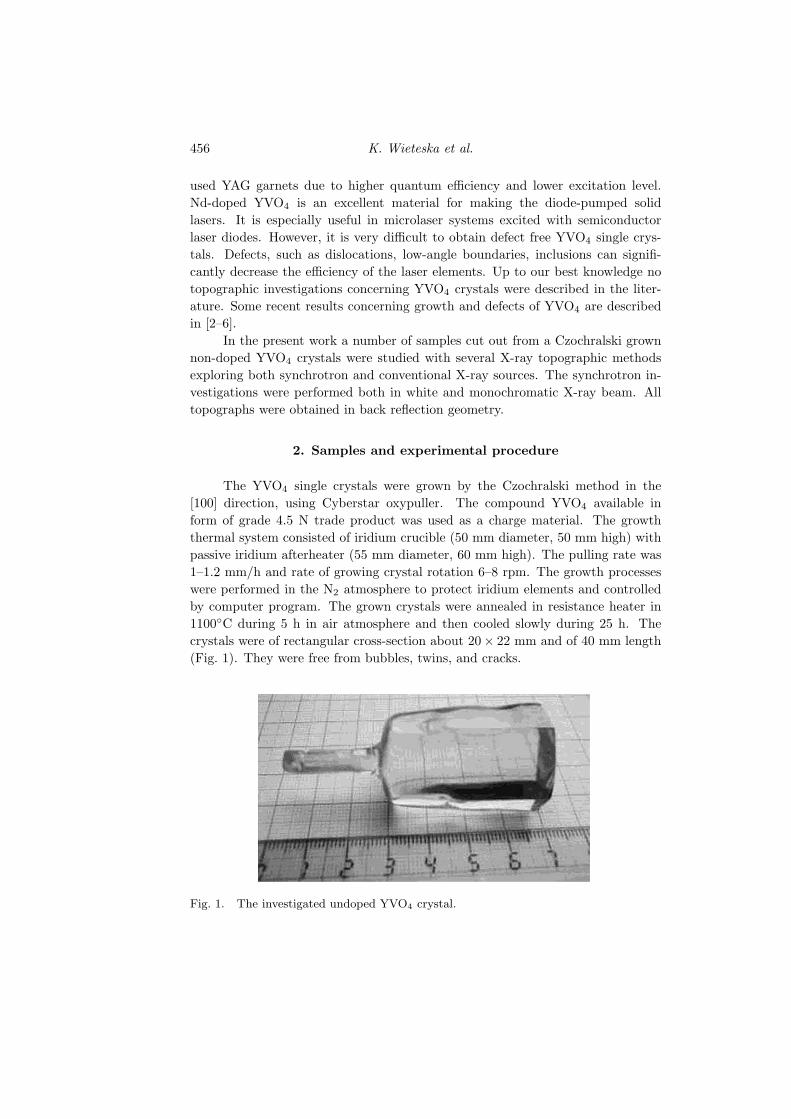
The YVO4 single crystals were grown by the Czochralski method in the[100] direction, using Cyberstar oxypuller. The compound YVO4 available inform of grade 4.5 N trade product was used as a charge material. The growththermal system consisted of iridium crucible (50 mm diameter, 50 mm high) withpassive iridium afterheater (55 mm diameter, 60 mm high). The pulling rate was1–1.2 mm/h and rate of growing crystal rotation 6–8 rpm. The growth processeswere performed in the N2 atmosphere to protect iridium elements and controlledby computer program. The grown crystals were annealed in resistance heater in1100◦C during 5 h in air atmosphere and then cooled slowly during 25 h. Thecrystals were of rectangular cross-section about 20× 22 mm and of 40 mm length(Fig. 1). They were free from bubbles, twins, and cracks.
Fig. 1. The investigated undoped YVO4 crystal.

X-RAY Topographic Studies of Defect Structure . . . 457
The samples denoted respectively A, B and C were cut out perpendicularto the growth axis from different regions of the crystal. The sample A was cutout from the region near the seed, B from the middle, and C from the end partof the same crystal. All samples were mechanically polished to the thickness of300 µm. A set of samples was selected to provide more complete informationabout the whole crystals. The growth condition in the starting and end parts areusually different than those in the middle part providing the most useful materialfor applications.
Some different topographic methods exploring both conventional and syn-chrotron sources of X-rays were used for the characterization of the crystal. Animportant advantage of conventional topographic methods is the possibility of re-producing the whole area of investigated samples. The presently used synchrotronmethods usually reproduce an area with a diameter of several millimeters providinghigh spatial resolution.
Conventional projection X-ray topographs were taken in back reflection ge-ometry using Mo Kα1 radiation. The topographs were recorded on 50 µm IlfordL4 nuclear plates.
The synchrotron radiation experiments were realized at stations F1 (whitebeam) and E2 (monochromatic beam) at HASYLAB (DESY, Hamburg) in backreflection geometry. In case of white beam synchrotron projection topographs(SRWB) relatively low glancing angles of 5◦ were used. The topographs wererecorded on film placed perpendicularly to the incident beam at the distances of10 and 20 cm from the crystal.
The samples were also studied by taking monochromatic beam topographs in0.115 nm radiation. The beam was formed by successive 333 and 511 symmetricalreflections from silicon crystals. In some cases, due to strong curvature of the sam-ple, the “zebra patterns” were taken. This kind of topograph is obtained, when thecrystal position is stepwise altered during exposition by a relatively small angle.In case of deformed crystal the “zebra pattern” reveals a series of stripes corre-sponding to the regions of crystal reflecting at each subsequent angular setting.In actual case the angular step was equal to 0.003◦. The synchrotron topographswere recorded for different azimuths of the crystal either on KODAK SR45 orSlavish holographic films. In all reproduced topographs dark tones correspond tohigh X-ray intensity.
3. Results and discussion
The topographic images of the samples A, B, and C are shown in Figs. 2,3, and 4, respectively. It should be noticed that the topographs obtained with allused methods did not reveal any segregation fringes in all three samples provinghigh homogeneity of chemical composition. The conventional back reflection to-pograph and SWBR topographs revealed a relatively high density (< 104 cm−2) ofweak point-like contrasts, which can be most probably interpreted as dislocation

458 K. Wieteska et al.
Fig. 2. X-ray projection topographs of sample A cut out near the seed of undoped
YVO4 crystal (d = 300 µm): (a) back reflection (800) reflection; (b)–(c) SRWB back
reflection of two different regions, direction of the beam projection along the normal
to (001) planes; (d) SRWB back reflection, direction of the beam projection along the
normal to (010) planes; (e)–(g) SR monochromatic plane wave, (400) reflection, λ =
0.115 nm, direction of the beam projection along the normal to (001) planes. The
pictures were taken for three angular positions passing the maximum of the rocking
curve; A — representative subgrain boundaries, B — representative glide bands.
outcrops. In some regions of the crystal close to its boundary we observed someglide bands as it may be seen in Fig. 2b, c. It was also found that in some re-gions the dislocations form local subgrain boundaries. The representative subgrainboundaries were marked in the topographs by “A” and representative glide bands
X-RAY Topographic Studies of Defect Structure . . . 459
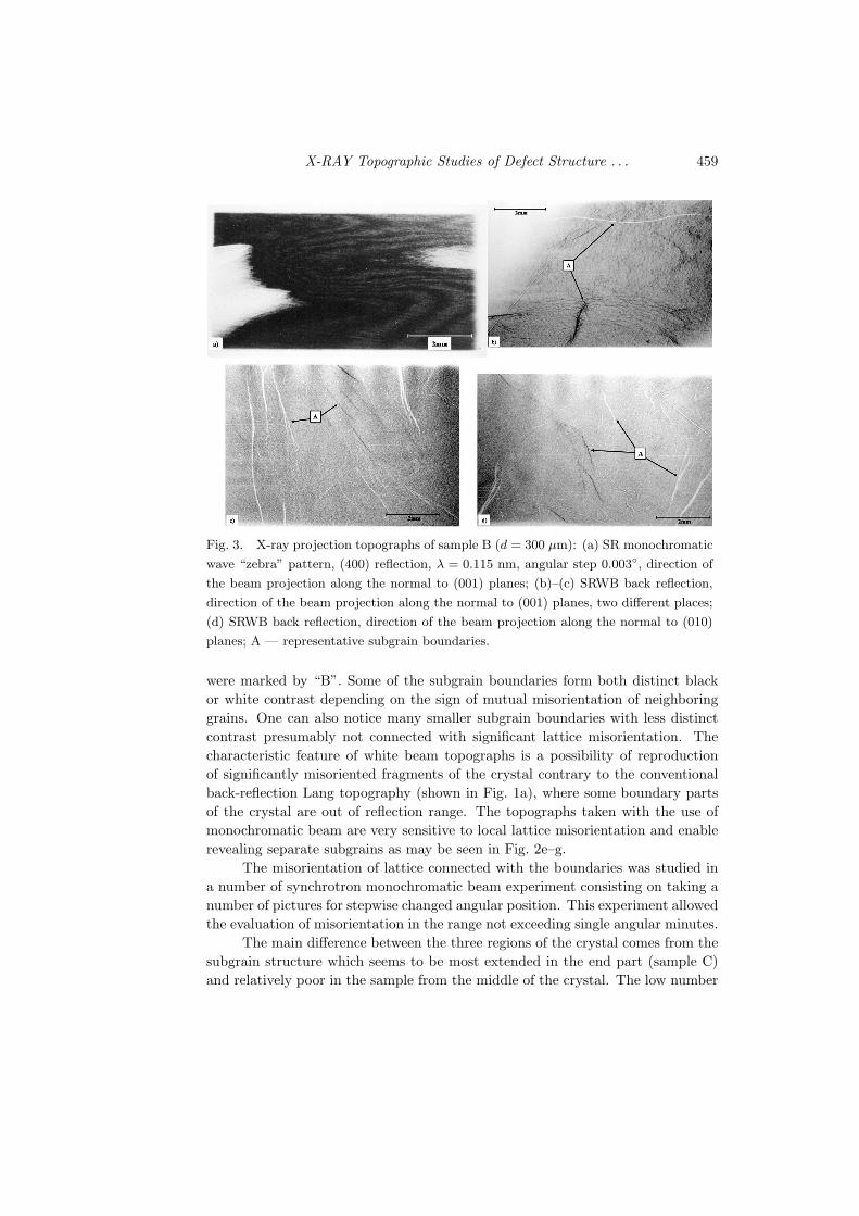
Fig. 3. X-ray projection topographs of sample B (d = 300 µm): (a) SR monochromatic
wave “zebra” pattern, (400) reflection, λ = 0.115 nm, angular step 0.003◦, direction of
the beam projection along the normal to (001) planes; (b)–(c) SRWB back reflection,
direction of the beam projection along the normal to (001) planes, two different places;
(d) SRWB back reflection, direction of the beam projection along the normal to (010)
planes; A — representative subgrain boundaries.
were marked by “B”. Some of the subgrain boundaries form both distinct blackor white contrast depending on the sign of mutual misorientation of neighboringgrains. One can also notice many smaller subgrain boundaries with less distinctcontrast presumably not connected with significant lattice misorientation. Thecharacteristic feature of white beam topographs is a possibility of reproductionof significantly misoriented fragments of the crystal contrary to the conventionalback-reflection Lang topography (shown in Fig. 1a), where some boundary partsof the crystal are out of reflection range. The topographs taken with the use ofmonochromatic beam are very sensitive to local lattice misorientation and enablerevealing separate subgrains as may be seen in Fig. 2e–g.
The misorientation of lattice connected with the boundaries was studied ina number of synchrotron monochromatic beam experiment consisting on taking anumber of pictures for stepwise changed angular position. This experiment allowedthe evaluation of misorientation in the range not exceeding single angular minutes.
The main difference between the three regions of the crystal comes from thesubgrain structure which seems to be most extended in the end part (sample C)and relatively poor in the sample from the middle of the crystal. The low number
460 K. Wieteska et al.
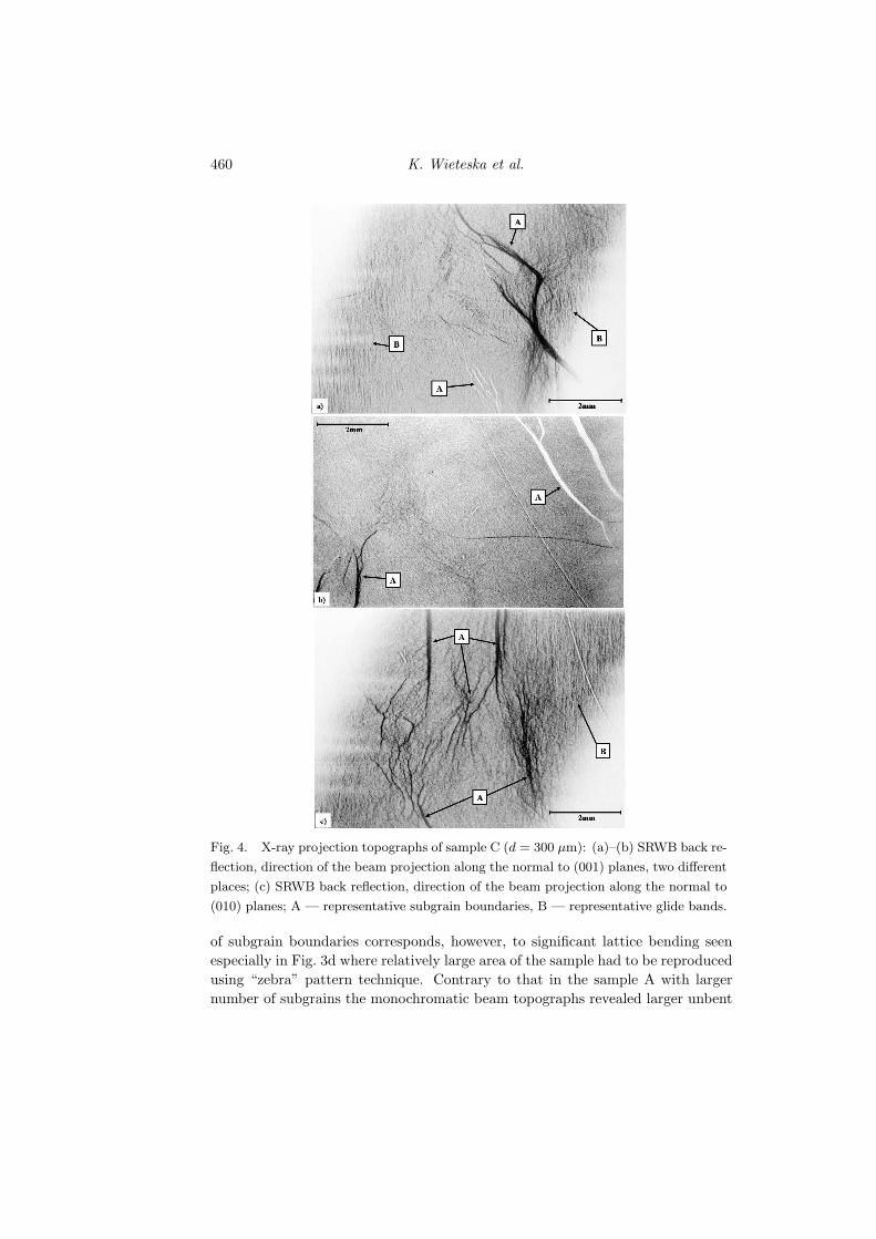
Fig. 4. X-ray projection topographs of sample C (d = 300 µm): (a)–(b) SRWB back re-
flection, direction of the beam projection along the normal to (001) planes, two different
places; (c) SRWB back reflection, direction of the beam projection along the normal to
(010) planes; A — representative subgrain boundaries, B — representative glide bands.
of subgrain boundaries corresponds, however, to significant lattice bending seenespecially in Fig. 3d where relatively large area of the sample had to be reproducedusing “zebra” pattern technique. Contrary to that in the sample A with largernumber of subgrains the monochromatic beam topographs revealed larger unbent

X-RAY Topographic Studies of Defect Structure . . . 461
blocks with mutual misorientation of several minutes as may be seen in Fig. 2e–g.Extended complex structure of subgrain boundary may be particularly seen inFig. 4b. Also the width of the grain boundaries contrasts was largest in thecase of the sample cut out from the end part of the crystal. The larger numberof subgrain boundaries and the extension of their contrast indicate larger stressoccurring in the growth process. In case of top part crystal the larger strainsare usually connected with enlarging of crystal diameter while in the case of theend part the formation of large strain is obviously connected with stopping of thegrowth process.
4. Conclusions
The YVO4 undoped crystals were grown by the Czochralski method provid-ing crystals of rectangular cross-section about 20 × 22 mm and of 40 mm lengthfree of visible cracks and inclusions.
The conventional and synchrotron X-ray topographic investigations were per-formed in back reflection geometry revealing the dislocation outcrops, glide bands,and subgrain boundaries. The generation of these defects is usually attributed tothe thermal stresses present in the growth process. The mutual misorientation ofcrystal blocks was evaluated to be of the range of several minutes.
The lowest concentration of subgrains was observed in the sample cut outfrom the middle part of the crystal, which is usually grown in more stable thermalconditions.
Acknowledgments
The technical assistance of J. Bondziul is much appreciated.
References
[1] S. Wu, G. Wang, J. Xie, X. Wu, G. Li, J. Cryst. Growth 249, 176 (2003).
[2] S. Wu, G. Wang, J. Xiea, J. Cryst. Growth 266, 496 (2004).
[3] H. Zhang, Y. Yu, Y. Cheng, J. Liu, H. Li, W. Ge, X. Cheng, X. Xu, J. Wang,
M. Jiang, J. Cryst. Growth 283, 438 (2005).
[4] M. Kruczek, E. Talik, H. Sakowska, W. Szyrski, Z. Ujma, D. Skrzypek, J. Cryst.
Growth 275, e1715 (2005).
[5] B.Q. Hu, Y.Z. Zhang, X. Wu, X.L. Chen, J. Cryst. Growth 226, 511 (2001).
[6] D.E. Eakins, J.B. LeBret, M.G. Norton, D.F. Bahr, J. Cryst. Growth 266, 411
(2004).