x-ray microtomography as a test method for the wear of
TRANSCRIPT
EJMT 3(20) 2018 • European Journal of Medical Technologies
31 Copyright © 2018 by ISASDMT
Corresponding address: Agata M. Niewczas, Medical University of Lublin, Chair and Department of Conservative Dentistry with Endodontics, ul. Karmelicka 7, 20-081 Lublin, [email protected]
Key words: indirect composite filling, wear, hewing simulator, X-ray microtomography
X-ray microtomography as a test method for the wear of composite dental restorations in laboratory conditions
AbstractIn laboratory tests of dental wear, the surface and structure of a teeth samples are observed under simulated environmental stress. Wear studies can substan-tially support the clinical applications of dental diagnostic testing. The aim of this study was to assess the usefulness of X-ray microtomography (XMT) for quantitative laboratory analysis of wear of a tooth with an indirect composite restoration. It should be noted that in the first phase of the fatigue test, the increased in wear was moderate. However, in the second phase of test, when the number of cycles exceeded 100,000, the wear rate was significantly higher. The results show that the presented test method can be successfully used to analyze the durability of composite restorations in vitro. The obtained results of wear measurements are in the range of 0.062 mm2 to 2.250 mm2, and their ac-curacy is comparable with the results of other authors’ research. The accuracy of the observation was 0.015 mm. These results were taken as the basis for a posi-tive assessment of the usefulness of the XMT method.
Agata M. Niewczas1, Krzysztof Kruszyński2, Paweł Kordos3, Andrzej Bożyk4, Paweł Jarosz5, Ireneusz Usydus5
1 Chair and Department of Conservative Dentistry with Endodontics, Medical University of Lublin, Poland
2 Kadent System, Rzeszów, Poland
3 Institute of Transport, Combustion Engines and Ecology, Lublin University of Technology, Poland
4 Department of Dental Prosthetics, Medical University of Lublin, Poland
5 Engineering Studies Centre, The Institute of Technical Sciences and Aviation, The State School of Higher Education in Chełm, Poland
European Journal of Medical Technologies 2018; 3(20): 31-42
Copyright © 2018 by ISASDMT All rights reserved www. medical-technologies.eu Published online 26.09.2018

EJMT 3(20) 2018 • European Journal of Medical Technologies
32 Copyright © 2018 by ISASDMT
IntroductionThe method of laboratory examination of tooth wear consists in observing the surface and struc-ture of the sample under the conditions of envi-ronmental simulation impacts. These studies can significantly support the clinical application of dental diagnostics. However, despite numerous research works in this in this regard, many prob-lems remain to be clarified. One of the important issues is the improvement of wear observation techniques, including the use of the x-ray microto-mography (XMT) method [1,2]. The development of x-ray microtomography method began in 1968 by Godfrey Newbold Hounsfield [3] created new possibilities in medical diagnostics and new re-search capacity in terms of improving methods of conservative and prosthetic treatment in dentistry. High accuracy of XMT method enables meticu-lous observation of morphological changes in the tooth- bonding layer- dental filling system. The resolving power of observation of detailed ele-ments of the two-dimensional tooth section hovers around 0,5-40 µm [3,4]. After calibration, a linear measurement of selected image details is possible. The measurement is made on the basis of pixel ad-dresses using the geometrical analysis method. The result is given automatically in the image of the cross section considered.
From the point of view of the subject of this work, the study of resistance to physical and mechanical wear associated with the chewing process in con-ditions of cyclically variable temperature and the corrosive effect of fluids in the oral cavity deserve special attention. Resistance to mechanical wear is one of the main factors determining the durability of composite filling- tooth system and condition for the clinical success. In 2006, Ferracane describ-ing the problem of durability of composite fillings, stated that their wear resistance is still unsatisfac-tory, especially where a large restoration in direct occlusal contact or in patients with bruxism above-mentioned fillings is needed [5]. It is worth men-tioning, that during the last 10 years, the number of scientific papers with regard to the use of dental
composites in the worldwide literature exceeded 300 [6].
Physical and mechanical wear of tooth- filling system may involve the structure of this system or occlusal surface of the teeth in contact.
In the first group relating to structural damages in the literature is mentioned (Fig. 1): [7,8]• cracking in the enamel area (A)• cracking in the filling area (B)• breaking or falling out of a tooth fragment (C)• breaking or falling out of the filling
fragment (D)The sizes of observed structural cracks, as well as
the size of the marginal fissure are assessed in the lit-erature in a different manner. According to the au-thors of the work [9, 26], the fissure width is between 10-20 µm, whereas in work [10, 26] it was found that after a four-year period of use in oral conditions, the fissure width is even approx. 20 ÷ 80 μm. In work [11], it was shown that in in vitro conditions, using 90,000 impact cycles with a force of 3.9 N, a margin-al fissure with an average width in the range of 3 ÷ 11 μm is observed. The length of the marginal fissure was 1 to 5 mm, and the area of the fissure observed on the longitudinal section of the tooth was in the range of 0.010 mm2 to 0.033 mm2. Laboratory obser-vations of microcracks in the filling material as well as in the hard tissues of the tooth prove that fatigue cracks always occur in the chewing process under the influence of cyclic mechanical loads [12]. The length of the microcracks ranges from 200 μm to 800 μm. In special cases, the expansion of structural cracks leads to breakage of fragments of the tooth's filling or tissue.
In the second group of wear defects concerning the surface of the teeth, wear is defined as the irreversible loss of material (tooth filling or tissue) resulting from the interaction between the contacting surfaces in the chewing process or mechanical-chemical interaction of foreign bodies. There are three main mechanisms of noncarious wear: attrition, abrasion and erosion (Fig. 2) [6].
Attrition is the abrasive wear of the contacting surfaces of the teeth without the involvement of ex-ternal factors. It is estimated that the physiological

EJMT 3(20) 2018 • European Journal of Medical Technologies
33 Copyright © 2018 by ISASDMT
process of atrium causes a loss of the enamel layer with a thickness of 20-30 μm per year [13].
Abrasion is abrasive or fatigue, which is the re-sult of, among others, prolonged bending of the lateral crown of the tooth or improper brushing of teeth [14,15].
Erosion is a progressive loss of hard tissues as a result of a chemical process without the partici-pation of bacteria due to the destructive interaction of endogenous or exogenous acids [14,15].
Symptoms of the wear of teeth treated conserva-tively may be:
• changing the contour of the chewing surface of the tooth or fill body
• emergence of marginal fissure or structural cracks in the tooth-binding layer-dental filling system.
Wear can be assessed by imaging areas subject to the surface or structural degradation processes described above and comparing the images ob-tained before and after use.
Aim of the researchThe aim of the study in this scientific paper was the assessment of the usefulness of the X-ray microto-mography (XMT) method for the quantitative analy-sis of tooth wear with intermediate composite filling in laboratory conditions.
Material and method
Object of study and preparation of samples
The object of study were human molar teeth, where the class I cavities according to Black were anato-mized. Cavities were filled with the indirect method using crown inlay. A light-curing, micro-hybrid Ce-ramage composite material was used for filling. It is a composite for making restorations in the front and lateral teeth. It contains over 70% ceramic filler.
Fig. 1. Schemes of wear defects in the structure of the tooth-filling system [7, 8]
a) b) c)
Fig. 2. Mechanisms of wear in dentistry: a) attrition, b) abrasion, c) erosion [6]
EJMT 3(20) 2018 • European Journal of Medical Technologies
34 Copyright © 2018 by ISASDMT
Ceramage absorbs well the stresses generated during chewing. It has good bending strength [16].
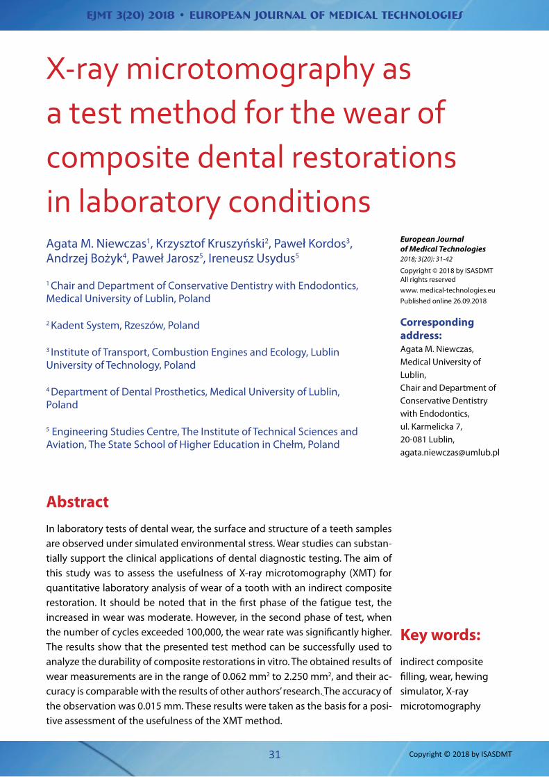
The load test was that two samples of filled teeth were paired and mounted in a chewing simulator, and then subjected to cyclic mechanical loads. A chew-ing simulator developed by the authors of this article was used [17,18]. Fig. 3 shows the diagram, and Fig. 4 shows the simulator. The simulator works as follows:• two teeth samples are fixed elastically and im-
mersed in a vessel containing artificial saliva• the upper sample is pressed in the vertical di-
rection with the given force, independent of the position
• the lower sample performs horizontal motion, modeled on the movement of the mandible in the mouth
It is possible to change the velocity of mutual translation of the samples with each other and the pressure force in the vertical direction and the free-dom of the trajectory configuration of the lower sample movement in the horizontal plane. Computer
simulator control system allows you to enter any number of repetitions chewing cycles.
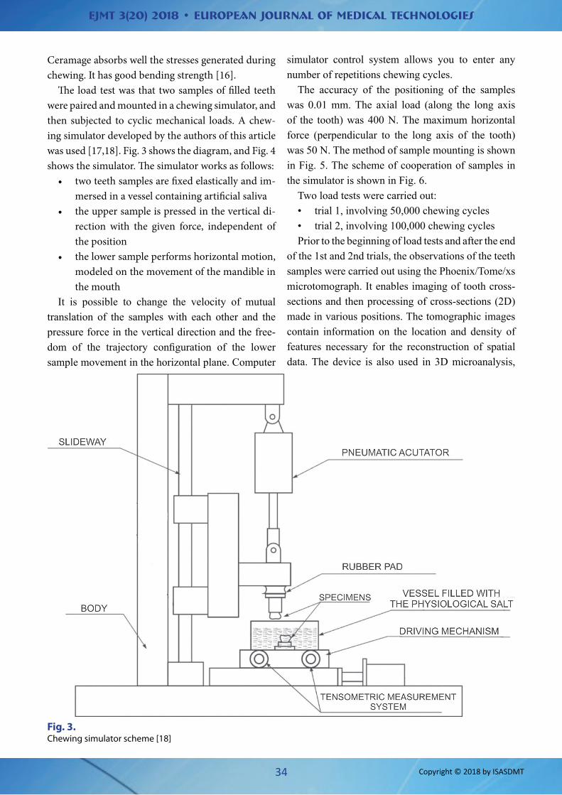
The accuracy of the positioning of the samples was 0.01 mm. The axial load (along the long axis of the tooth) was 400 N. The maximum horizontal force (perpendicular to the long axis of the tooth) was 50 N. The method of sample mounting is shown in Fig. 5. The scheme of cooperation of samples in the simulator is shown in Fig. 6.
Two load tests were carried out:• trial 1, involving 50,000 chewing cycles• trial 2, involving 100,000 chewing cyclesPrior to the beginning of load tests and after the end
of the 1st and 2nd trials, the observations of the teeth samples were carried out using the Phoenix/Tome/xs microtomograph. It enables imaging of tooth cross-sections and then processing of cross-sections (2D) made in various positions. The tomographic images contain information on the location and density of features necessary for the reconstruction of spatial data. The device is also used in 3D microanalysis,
Fig. 3. Chewing simulator scheme [18]

EJMT 3(20) 2018 • European Journal of Medical Technologies
35 Copyright © 2018 by ISASDMT
Fig. 4. View of the chewing simulator [18]
Fig. 5. The method of mounting samples in the simulator [18]
EJMT 3(20) 2018 • European Journal of Medical Technologies
36 Copyright © 2018 by ISASDMT
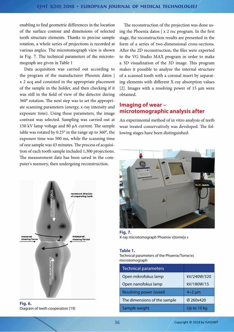
enabling to find geometric differences in the location of the surface contour and dimensions of selected tooth structure elements. Thanks to precise sample rotation, a whole series of projections is recorded at various angles. The microtomograph view is shown in Fig. 7. The technical parameters of the microto-mograph are given in Table 1
Data acquisition was carried out according to the program of the manufacturer Phoenix datos | x 2 acq and consisted in the appropriate placement of the sample in the holder, and then checking if it was still in the field of view of the detector during 360° rotation. The next step was to set the appropri-ate scanning parameters (energy, x-ray intensity and exposure time). Using these parameters, the image contrast was selected. Sampling was carried out at 150 kV lamp voltage and 80 μA current. The sample table was rotated by 0.25° in the range up to 360°, the exposure time was 500 ms, while the scanning time of one sample was 43 minutes. The process of acquisi-tion of each tooth sample included 1,300 projections. The measurement data has been saved in the com-puter's memory, then undergoing reconstruction.
The reconstruction of the projection was done us-ing the Phoenix datos | x 2 rec program. In the first stage, the reconstruction results are presented in the form of a series of two-dimensional cross-sections. After the 2D reconstruction, the files were exported to the VG Studio MAX program in order to make a 3D visualization of the 3D image. This program makes it possible to analyze the internal structure of a scanned tooth with a coronal insert by separat-ing elements with different X-ray absorption values [2]. Images with a resolving power of 15 μm were obtained.
Imaging of wear – microtomographic analysis after An experimental method of in vitro analysis of teeth wear treated conservatively was developed. The fol-lowing stages have been distinguished:
Fig. 6. Diagram of teeth cooperation [19]
Fig. 7. X-ray microtomograph Phoenix v|tome|x s
Table 1. Technical parameters of the Phoenix/Tome/xs microtomograph
Technical parameters
Open mikrofokus lamp
Open nanofokus lamp
kV/240W/320
kV/180W/15
Resolving power (voxel) 4÷2 µm
The dimensions of the sample Ø 260x420
Sample weight Up to 10 kg

EJMT 3(20) 2018 • European Journal of Medical Technologies
37 Copyright © 2018 by ISASDMT
a. each time, on the longitudinal section of the tooth, the edge of the observation area with a homogeneous texture was determined - ac-cording to the principle of image segmentation on a field of uniform brightness reflecting the actual area of the tissues examined [2]
b. the location of the edge (contour) of the exam-ined observation area before and after the fa-tigue load was compared
c. the surface area determined by the difference in the position of the edge of the observation field was analyzed quantitatively, so that a grid of elementary fields of the image with a size of 0.25x0.25 mm was determined, and then the surface area of these fields was added, thus de-termining the total field of wear in the plane of a given tooth cross-section
d. it was assumed that the above field is an indica-tor of tooth wear in the analyzed cross-section. This indicator is called the face of wear (FW).
Research resultsFig. 8 shows an example of a cross-sectional image of the examined tooth Z1.
Fig. 8 shows the characteristic details of the tooth structure with the filling and their dimensions (di-mensioning carried out directly by the microtomo-graph). It is worth paying attention to the subsurface loss of the cement layer. The width of the resulting fissure is 0.160 mm. An outstanding detail (defect) is also the structural "void" in the cement layer. The result of the measurement of the "void" width is 0.64 mm. It should be emphasized that none of the analyzed cross-sections of the tested teeth Z1 and Z2 revealed marginal leak between the filling and the binding layer (cement) and enamel. This dem-onstrates positively the effectiveness of the indirect method of insertion of composite fillings using crown inlays [20,21,22].
Fig. 8. Microtomographic image of a tooth cross-section with a filling after 100,000 chewing cycles

EJMT 3(20) 2018 • European Journal of Medical Technologies
38 Copyright © 2018 by ISASDMT
Based on the results obtained, it was assessed that the effective (practical) accuracy of imaging of mi-crotomographic cross-sections in the conditions of the tests was 0.01 mm. Comparing tooth im-ages made before the fatigue test and after the first trial (50 thousand cycles) and after the second trial (100 thousand cycles) one can measure the change
in the position of the contour of the chewing surface of the tooth. This change can be a measure of tooth wear. An exemplary picture of a tooth's cross-section (Z1 tooth, R3 cross-section) is shown in Fig. 9. The result of a linear measurement of wear in a selected puncture determined directly by the microtomo-graph is marked.
In the present work, in order to quantify the wear of the tooth surface, the surface area determined by the difference in the position of the tooth's cross-section before and after the load test was taken as the face of wear. It is a 2D indicator providing more complete information about wear than the linear indicator il-lustrated in Fig. 9. Images of selected cross-sections with correlated coordinates of the tested pair of teeth Z1 and Z2 and the results of quantitative analysis of FW wear are shown in Fig. 10 and Fig. 13. Numerical results of the face of wear in tested pair of teeth Z1 and Z2 in cross-section R1 are given in Table 2.
Fig. 9. A linear dimension of wear at a selected point of the tooth surface after 100,000 chewing cycles (area x 14.66)
Fig. 10. A microtomographic image of Z1 in section R1 after execution of a) 0 chewing cycles; b) 50 thousand chewing cycles; c) 100 thou-sand chewing cycles
a) Z1 R1 0k
b) Z1 R1 50k
c) Z1 R1 100k

EJMT 3(20) 2018 • European Journal of Medical Technologies
39 Copyright © 2018 by ISASDMT
Table 2. Results of measurement of the face of wear profile of teeth Z1 and Z2 on the chewing surface in section R1 after 50,000 and 100,000 cycles of chewing
Teeth samples Cross-section (coordinates) Area of wear cross-section [mm2]
0-50k 50-100k 0-100kZ1 (upper tooth) R1 0.3125 1.9375 2.2500Z2 (lower tooth) R1 0.0625 0.4375 0.5000
Figures 10 and 12 show the selected longitudinal tooth section respectively Z1 and Z2 before and af-ter the load test. The cross-sections in Figures 10a, 10b and 10c and in Figs. 12a, 12b, 12c have mutually compatible coordinates. The difference in the posi-tion of the edges of these cross-sections determines the profile of the area of tooth wear on the chewing surface. The wear of the tooth Z1, fixed in the sim-ulator as the upper tooth, was 50,000 cycles FW1 (50k) = 0.3125, and 100,000 cycles FW1 (100k) = 2.2500 mm2. The wear of the tooth Z2, fixed in the simulator as a lower tooth, was 50,000 cycles FW2 (50k) = 0.0625, and 100,000 cycles FW2 (100k) = 0.500 mm2.
It should be noted that in the first period of the fa-tigue test wear increase is of moderate character. How-ever, in the second load test period, after exceeding 100,000 load cycles, wear increases are significantly higher. Such a result of the observation indicates that the dynamics of wear increase in the second part of the sample augments sharply. On this basis, the pre-sented test method can be used to analyze the dura-bility of composite fillings in vitro. It is worth noting that the obtained results of wear measurements are in the range of 0.0625 mm2 to 2.2500 mm2 and are com-parable in the aspect of accuracy with the results of investigations of other functional failure phenomena [23,24,25].
Fig. 11. Scheme of measurement of the face of wear of the tooth Z1 in section R1 with the use of metric grids (1 grating = 0.25 mm x 0.25 mm); red line - 0 chewing cycles, blue - 50 thousand chewing cycles, green – 100 chewing cycles

EJMT 3(20) 2018 • European Journal of Medical Technologies
40 Copyright © 2018 by ISASDMT
Fig. 12. Z2 microtomographic image in R1 cross-section after execution of a) 0 chewing cycles; b) 50 thousand chewing cycles; c) 100 thousand chewing cycles
Z2 R1 0k
Z2 R1 50k
Z2 R1 100k

EJMT 3(20) 2018 • European Journal of Medical Technologies
41 Copyright © 2018 by ISASDMT
Conclusions1. On the basis of the studies the usefulness of the
X-ray microtomography (XMT) method for in vitro analysis of surface and structural wear of composite fillings is positively evaluated.
2. The tests have shown the effectiveness of the XMT method in the imaging and dimension-ing of geometrical and structural defects of the tooth - the binding layer – filling system.
3. The accuracy of XMT imaging under the in vi-tro test conditions described is estimated to be 0.01 mm.
4. The accuracy of physical and mechanical wear evaluation of the chewing surface of the tooth using the XMT method under the described conditions is estimated at 0.020 mm (linear wear at the chewing surface of the tooth) and 0.0625 mm2 (wear profile at the longitudinal section of the tooth).
5. No marginal leakage was detected using crown inlay from the composite material.
The research was conducted at the Centre of En-gineering Studies of the State School of Higher Ed-ucation in Chełm within the project "Laboratory of Environmental Studies CSI PWSZ in Chełm," co-financed by the European Fund of Regional Devel-opment (part of the Operational Programme Eastern Poland) 2007-2013.
References1. Różyło TK, Różyło-Kalinowska I, Radiologia stoma-
tologiczna, PZWL, Warszawa 2007.2. Strzelecki M, Materka A Tekstura obrazów biome-
dycznych PWN, Warszawa 2017.3. Heljak M, Jaroszewicz J, Święszkowski W, Kuszy-
dłowski KJ. Mikrotomografia rentgenowska jako metoda obrazowania w inżynierii materiałowej, Badania Nieniszczące 1/08/2009. http://www.badania-nieniszczace.info/Badania-Nienisz-czace-Nr-01-08-2009/Serwis-Badania-Nienisz-czace-01-08-2009-art-nr2.html.
4. Różyło-Kalinowska I, Różyło TK. Współczena ra-diologia stomatologiczna. Wyd. Czelej Sp. z o.o., Lublin 2015.
5. Ferracane JL. Is the wear dental composites still a clinical concern? Is there still a need for in vitro wear simulating devices. Dent Mater 2006; 22: 689-92.
6. Tsujimoto A, et al. Wear of resin composites: cur-rent insights into underlying mechanisms, evalu-ation methods and influential factors. Jap. Dent Sc Rev 2017, doi.org/10.1016/jdrs.2017.11.002.
7. Mielnik–Błaszczak M, red. Materiały kompozyto-we i szklano–jonomerowe w praktyce stomatolo-gicznej, Wyd. Czelej Sp.z o.o., 2002, Lublin.
8. Roulet JF Benefits and is advantages of tooth–coloured alternatives to amalgam. J Dent 1997; 25(6): 459–473.
9. Niewczas A, Kordos P, Kruszyński K, Bożyk A Mi-krotomograficzne badania porównawcze trwało-ści wypełnień z wykorzystaniem symulatora żucia. Międzynarodowa Konferencja Naukowa Sekcji
Fig. 13. Scheme of measurement of the face of wear of the tooth Z2 in cross-section R1 using a metric grid (1 grid = 0.25 mmx 0.25 mm); red line – 0 chewing cycles, blue – 50 thousand chewing cycles, green – 100 chewing cycles

EJMT 3(20) 2018 • European Journal of Medical Technologies
42 Copyright © 2018 by ISASDMT
Stomatologii Zachowawczej Polskiego Towarzy-stwa Stomatologicznego i Oddziału PTS w Białym-stoku. Białystok, 2017: 47.
10. Walczak M, Niewczas A. Mikroskopowa ocena przylegania brzeżnego wypełnień w zębach sta-łych. Inż. Biomat; 2007; 87–89.
11. Niewczas A. Badania wybranych materiałów sto-matologicznych do wypełnień stałych w aspekcie szczelności brzeżnej metodą in vitro. Praca dok-torska, Uniwersytet Medyczny w Lublinie; 2002.
12. Pieniak D, Niewczas A. M Phenomenological eva-luation of fatigue cracking of dental restorations under conditions of cyclic mechanical loads Acta of Bioeng and Biomech 2012; 14(2).
13. Braem M, Finger WV, Van Doren P, Lambrechts G, Vanherle G. Mechanical properties and filler frac-tion of dental composites. Dent Mater 1989; 5(5): 346-349.
14. Hryncewicz M, Tropak K, Ubytki niepróchnicowe-go pochodzenia – abfrakcja, atrycja, erozja. Nowa Stomat. 2014; 1: 46-52.
15. Kaczmarek U, Soltan E. Ocena erozji zębów po-chodzenia endogennego i egzogennego za po-mocą wskaźnika BEWE. Dent Med. Probl; 2011; 1(48): 23-29.
16. www.shofu.com17. Niewczas A, Hunicz J. Urządzenie do symulacji ob-
ciążeń mechanicznych zębów ludzkich leczonych zachowawczo. Acta Bioengin Biomech 2004, Vol. 6, Suppl. 1, 182-186.
18. Hunicz J, Niewczas A.M, Kordos P, Pieniak D. Expe-rimental test stand for analysis of composite den-tal fillings degradation Eksploat i Niezawodn Ma-int and Reliab 2007; 9(2):37-43.
19. Hunicz J, Niewczas AM, Kordos P. The station for accelerated fatigue tests of dental materials. Eks-ploatacja i Niezawodność Maintenace and Relia-bility 2009; 11(1): 63-69.
20. Stappert CFJ, Chitmongkolsuk S, Nelson R, Silva F.A, Atte W, Strub JR. Effect of mouth–motion fati-gue and thermal cycling on the marginal accuracy of partial coverage restorations made of various. Dent Mater 2008; 24: 1248–1257.
21. Niewczas A, Kruszyński K, Kordos P. Effectiveness of X-ray microtomography in the quantitative de-termination of wear of dental fillings in in vitro conditions. XI Międzynarodowa Konferencja Na-ukowo-Szkoleniowa "Środowisko a stan zdrowia jamy ustnej". Lublin 2018; 112-113.
22. Belli R, Geinzer E, Muschweck A, Petschelt A, Loh-bauer U Mechanical fatigue degradation of cera-mics versus resin composites for dental restora-tions. Dent Mater; 2014; 30: 424–432.
23. Hoa T.K, Satterthwaitea JD, Silikasa N. The effect of chewing simulation on surface roughness of resin composite when opposed by zirconia ce-ramic and lithium disilicate ceramic. https://doi.org/10.1016/j.dental.2017.11.014.
24. Arola D. Fatigue testing of biomaterials and their interfaces. Dent Mater; 2017; 33: 367–381.
25. Quinn JB, Quinn GD. Material properties and frac-tography of an indirect dental resin composite, Dent Mater 2010; 26: 589–599.
26. Ostapiuk M, Tarczydło B, Surowska B, Orłowski M, Tymczyna B, Bachanek T, Rzepecka A, Mróz A. Qu-alitative analysis of themargins of restorations made with different filling resins. Micro Res Tech, 2018, DOI: 10.1002/jemt.23041.