x-ray air conditioning unit glendon hospital … · x-ray air conditioning unit glendon hospital...
TRANSCRIPT
INVITATION TO TENDER
X-RAY AIR CONDITIONING UNIT
GLENDON HOSPITAL
October 25th, 2017

1
Ministry of Health & Social Services
Health Headquarters P. O Box 24 Tel: (664) 491-2552/2880
Brades MSR1110 Fax: (664) 491-3131
Montserrat. W. I. Email: [email protected]
October 25th, 2017 Dear Sir/Madam, Re: Tender for the Supply, Delivery, Installation, Commission and Maintenance of Two AC systems for the X-Ray room at the Glendon Hospital. Tenders are invited for the Supply, Delivery, Installation, Commission and Maintenance of Two AC systems complete for the X-Ray room at the Glendon Hospital. The systems must be Data Room air-conditioning units with integral humidity control. The Precision Cooling system must comprise a 36,000 BTU/Hr Up-flow Indoor Evaporator and 36,000 BTU/Hr Propeller Fan Condensing Unit. Included are the tender documents consisting of:
1. Instruction to Tenderers 2. Tender Check List 3. Form of Tender 4. Bill of Quantities 5. General Conditions of Contract 6. Anti-Collusion Statement 7. Evaluation Criteria 8. Post Contract Evaluation 9. Schedule A - Maintenance Schedule and Programme of Works 10. Schedule B - Method Statement 11. Schedule C - Warranty Information for AC units and all Equipment 12. Schedule D - Proposed Payment Schedule 13. Consultant Technical Specifications 14. Consultant Drawings
All Tender packages can be accessed on the Government of Montserrat website at www.gov.ms. Please return a Completed set of documents, the priced Bill of Quantities, completed and signed Form of Tender, Completed Document Check List, signed anti-collusion statement, Completed Schedules A - D and a copy of your tax compliance certificate (if locally based). These should be placed in a sealed inner envelope and addressed to The Chairperson, Public Procurement Board, Ministry of Finance and Economic Management, Government Headquarters, Brades, MSR1110, Montserrat. The name of the project should also be written on this inner envelope and should read, “Tender for the Supply, Delivery, Installation, Commission and Maintenance of Two AC systems for the X-Ray room at the Glendon Hospital”. The name of the tenderer should also be written on the inner envelope. This envelope should be placed into an outer envelope addressed to The Chairperson, Public Procurement Board, Ministry of Finance and Economic Management, Government Headquarters, Brades, MSR1110, Montserrat. The name of the project should also be written on this outer envelope and should read, “Tender for the Supply, Delivery, Installation, Commission and Maintenance of Two AC systems for the X-Ray room at the Glendon Hospital”. The outer envelope should bear no identification of the tenderer.

2
Tenders are to be received no later than 2:00p.m on Wednesday November 15th 2017. Please ensure that no additional marks are placed on the outer envelope. Tenders are to be taken to the Ministry of Finance and Economic Management where the tenderer would place his/her tender in the Tender Box and be given a receipt after this is completed. Any queries relating to the tender or works included should be made in writing to Linda Dias, Government Architect MCWL at [email protected] or Permanent Secretary at Ministry of Health, at [email protected]. Yours faithfully,
…..……..……….… Dorothea Hazel Permanent Secretary (Ag) Ministry of Health
Page IT/1
SUPPLY, DELIVERY, INSTALLATION, COMMISSION AND MAINTENANCE OF TWO AC SYSTEMS FOR THE X-RAY ROOM AT THE
HOSPITAL
Tender Documents and Instructions A Tenderers will be supplied with the following
tender documents-: - Tender Dossier - Tender Drawings
B Invitation Letter C Tender Drawings
D Tender Documents and Bill of Quantities
E One copy of the above mentioned tender document will be supplied to tenderers.
Tenderers must comply strictly with the following instructions as failure to do so will result in your tender being rejected.
F. Documents to be submitted together with the Form of tender:
1. Tender Document Check List 2. Form of Tender 3. Bill of Quantities 4. Tax Compliance certificate (if locally based) 5. Signed Anti-Collusion Statement 6. Method Statement/Risk Assessment 7. Proposed Payment Schedule 8. Supplier Technical Specifications 9. Maintenance schedule 10. Program of works 11. Warranty Information for AC units and all Equipment
G This tender is based on the Drawings, Technical Specifications, General Conditions of contract, Bill of Quantities including Schedules A to D (measured works section), hereinafter is referred to as the Contract Documents.
Page IT/2
Scope Statements Tenderer’s are required to complete all the works as described in the Scope statement, Supplier Technical Specifications, Design Drawings, and Bill of Quantities which are provided to the tenderers. The Contract provides for but is not necessarily limited to the Supply, Delivery, Installation, Commission and Maintenance of all the works included as listed below:
A All Equipment as listed for the Precision Cooling Air-Conditioning system
comprising a 36 000 BTU/Hr Up-flow Indoor Evaporator and a 36 000 BTU/Hr Propeller Fan Condensing Unit as specified in the Technical specifications
B All the Electrical and Control Wiring systems complete for Precision Cooling Systems,
and Motorized Opposed Blade Dampers. C The supply and installation of new and the modification of existing Low Velocity
Ductwork, Sheet Metal Ductwork, Fibre-glass Insulation and all Miscellaneous items such as Splitters, turning vanes all as indicated on the Consultants drawings.
D The supply and installation of new Diffusers, Grilles and Dampers including return air
grilles, supply registers, weatherproof louvre and Miscellaneous accessories. E The supply and installation of new seamless refrigeration and Condensate Piping and
Insulation. F Balancing, Testing and Adjustment of the total Air-Conditioning System by an
approved M&E Engineer to meet the design Conditions in accordance with the Design Drawings and Technical Specifications.
G Provide Electrical Service and Equipment to include 460/230-Volts, 3-Phase, 4-wire,
50-Hertz: All equipment shall be capable of accepting without ill effects, voltage variations of 8.5% above and below the above-mentioned mains voltage.
Page IT/3
Explanation of Documents
A If any point/s in the documents issued for the purpose of tendering are not clear, the
tenderer is especially asked to telephone the Public Works Department at +664 491
6611 or +664 491 8566 to clarify any Queries; on the drawings in the Bill of
Quantities or in the Specifications. The Government Architect will provide
explanations by the issue of an addendum to confirm answers given, and not less
than 7 working days prior to the date fixed for the delivery of tenders, and a copy of
such addendum will be dispatched to all parties who have interest in the tender
documents. Any addendum so issued will be incorporated in the contract documents.
All information given on the drawings and in the Technical Specification or in the
contract documents relating to materials quality, durability, assembly, protection,
insulation properties, noise and vibration control for the proposed system, is from the
best source available to the Employer at preparation of tender documents. All such
information is furnished only for the information and convenience of tenderers.
Statements to Tenderer
A Neither the Employer; Government of Montserrat, nor any of its agents or servants
shall be bound by or held liable for any statement made or delivered to any tenderer
unless such a statement shall have been confirmed by a circular letter to tenderers
issued by the Government Architect.
B Each Tenderer shall familiarize itself with all services to be installed under this and
any sub-contracts and bring to the attention of the Government Architect any apparent
areas of conflict, at an early enough stage to ensure that appropriate steps can be
taken and instructions issued, without jeopardizing any aspects of the various services
installations and the finished building as a whole.
C Tenderers are to provide for special attendance to include for the necessary costs in
relation to the Employment of any and all Specialist Trades required to carry out any
works related to the successful completion of the contract. This should include all
Page IT/4
travel, accommodation, and any other expense and include for their safe return at the
end of the contract.
D Tenderers are advised that the Government of Montserrat in an effort to improve
Contractor Performance and provide Client satisfaction in achieving value for money,
will undertake a ‘Contractor Performance Report’ at the end of contract. A form has
been included in the tender pack and this will be the tool used to measure and assess
the contractor’s performance in achieving the project objectives. The contractor
performance during contract implementation will be assessed at close out of the
contract. Please be advised that the Client’s satisfaction for the completed works with
respect to time, cost and quality will form part of the measureable indicators, to
determine successful completion and delivery of the project.
Tenderer to Investigate Before Tendering
A The tenderer will be deemed to have read and examined all the documents in the
Tender pack including the Technical Specifications and he/she shall satisfy him or
herself as to all matters and eventualities which can in any way influence his or her
tender. Any neglect or failure on the part of tenderers to obtain reliable information
upon any matters affecting the cost, time, quality, execution, construction,
completion, testing, commissioning and maintenance of the Works and the Contract
shall not relieve the persons whose Tender is accepted from any risks or liabilities for
the complete Works, nor will any claim for increase of the Contract be entertained as
a result of such Tenderer negligence.
B The tenderers are required to visit and examine the site and its surroundings, and
he/she may obtain for him or herself all the information that may be necessary for
compiling his or her tender. He/she must examine the tender documents and
determine the matters on which he/she considers a risk. Therefore, submission of
his/her tender shall be considered conclusive evidence that the Contractor has
satisfied him or herself of all the risks and obligations which the Contract will impose.
Page IT/5
C The tenderer shall submit his or her tender with the understanding that the tender
documents are intended to cover all the work within the scope of the Contract, and
that unless expressly excluded, any and all labour and materials not indicated therein,
but necessary to complete any part of work, shall be considered as included and shall
be furnished.
D Any alteration made by a tenderer to the documents issued for the purpose of
tendering or omission by him or her to complete fully and return every document as
required by this notice to tenderers, unless otherwise instructed by the Government
Architect, may preclude consideration of the tender by the Employer. Should any
further information be required, it will be supplied to the Tenderer by the Government
Architect.
Technical Specifications
A The information contained within the Technical Specification do not necessarily
indicate conclusively the amount or the extent of works to be performed. The
tenderer must satisfy himself or herself as to the general accuracy of the information
given in the Technical Specification and must provide accordingly in his tender
submission. If he/she considers that any quantity differs significantly from that
provided in the Consultant Technical Specification, he/she must call attention to the
fact in a letter accompanying the tender. The tenderer must provide for all his/her
obligations under the Contract. An all-in rate comprising of labour, material,
transportation, duty and plant must be entered against every item in the Supplier
Technical Information. If any item is left un-priced it shall be deemed as allowed for
elsewhere. The schedules must also be completed if provided in the tender
documents.
Bills of quantities
A Quantities contained within the Bills of Quantities do not necessarily indicate
conclusively the amount or the extent of works to be performed. The tenderer must
satisfy himself or herself as to the general accuracy of the quantities given in the bill of
quantities and must provide accordingly in the tender rates. If he/she considers that
any quantity may differ materially from the figure given in the bills of quantities, he/she
Page IT/6
must call attention to the fact in a letter accompanying the tender. The tenderer must
not insert additional items in the bills of quantities, but must provide for all his/her
obligations under the Contract in the rates and prices entered against the items
provided. An all-in rate comprising of labour, material, transportation and plant must
be entered against every item in the bills of quantities. If any item is left un-priced it
shall be deemed as allowed for elsewhere.
Currency of Tender
A Tenders shall be priced in EC. Eastern Caribbean Dollars or XCD. Rates and prices
shall be inclusive of applicable taxes. In order to keep the bidding process as fair and
simple as possible, please bid as a duty paid project.
B The tenderer must familiarize himself/herself with the workings of the Customs
Department and shall allow for the costs of and shall accept responsibility for
preparing and processing the necessary documents involved in the importation of
labour and materials, including Specialists trades etc. to be incorporated in the Works.
C The tenderer must allow for all Wharfage Dues, Package Tax, Importer's Licenses
(where applicable), Stamp Duties, taxes and charge that may be required.
D Special rules are in force in respect of the importation of plant, scaffolding, tools,
equipment and consumable stores that are not incorporated in the Works. The
tenderers must allow for the result of licenses, bond deposits, duties, taxes, stamp
duties or any other charges that may be required.

Page IT/7
Return of Tenders
Tenders shall be sent to: -
A The Chairperson
Public Procurement Board
Ministry of Finance and Economic Management,
Government Headquarters,
Brades,
Montserrat
B Please return the complete document of the priced and signed Form of Tender, Bill
of Quantities, Completed Document Check List, signed anti-collusion statement
and a copy of your tax compliance certificate (if locally based). These should be
placed in an inner envelope and addressed to The Chairman, Public
Procurement Board, Ministry of Finance and Economic Management, Brades
MSR1110, Montserrat. The name of the project should also be written on this
inner envelope and should read, “TENDER FOR THE SUPPLY, DELIVERY,
INSTALLATION, COMMISSION AND MAINTENANCE OF TWO AC SYSTEMS
FOR THE X-RAY ROOM AT THE GLENDON HOSPITAL”. The name of the
tenderer should also be written on the inner envelope.
This envelope should be placed into an outer envelope addressed to The Chairman, Public Procurement Board, Ministry of Finance and Economic Management, Brades, MSR1110, Montserrat. The name of the project should also be written on this outer envelope and should read, “TENDER FOR THE SUPPLY, DELIVERY, INSTALLATION, COMMISSION AND MAINTENANCE OF TWO AC SYSTEMS FOR THE X-RAY ROOM AT THE GLENDON HOSPITAL”. The outer envelope should bear no identification of the tenderer. Tenders are to be received no later than 2:00pm on Wednesday 15th November 2017. Please ensure that no additional marks are placed on the outer envelope. Tenders shall be made on the appropriate Form of Tender included in the tender
Page IT/8
Information to be Completed by the Tenderer
A Tenderer shall complete the tender documents so provided. Each Tender must
contain the name, residence and place of business of the person or persons
making the Tender and must be signed by the Tenderer with his usual signature.
Tenders by partnership must furnish the full names of all partners and must be
signed with the partnership name by one of the members of the partnership or by
an authorized representative followed by the signature and designation of the
person signing. Tenders by corporation to be signed with the legal name of the
corporation followed by the date and name of the State of incorporation and by the
signature and designation of the President, Secretary or other person authorized to
bind it in the matter. Satisfactory evidence of the authority of the signer on behalf of
the firm shall be furnished.
Responsibility for Tender
A The Employer, Government of Montserrat will not be responsible for, or pay for, any
expense or loss which may be incurred by the tenderer in the preparation of his
tender.
B The Tenderer to whom the award is made may be required to furnish, and deliver
to the Employer, a written bond of indemnity, of the same form as that in security
forms section of the tender document, in the amount of ten percent (10%) of the
Contract Price, and with surety thereon acceptable to the Employer. The bond
shall be furnished and maintained at the expense of the Contractor. The party to
whom the Contract is awarded will be required to execute the Contract and (if
required) furnish the Performance Bond duly executed within seven days, not
including Sunday or Legal Holiday. Failure to execute the Contract shall be
sufficient reason for the Government Architect to cancel the award without
obligation or claim upon the Employer.
Page IT/9
A Increases / Decreases in Cost of Labour and Materials
i. Increases / decreases in the current cost of labour and materials subsequent
to the date for closing of Tenders will not result in an adjustment to the
Contract Price.
ii. Basic unit costs of labour and certain materials upon which the Tender is
based and upon which day works and variations will be considered shall
be listed in the Schedule listed in the preliminary Appendix. These
Schedules shall be completed and submitted with the Tender. Failure to
submit them may lead to disqualification of the Tender.
Bribery
A The offer of a bribe or other inducement to any person with the object of influencing
the placing of the Contract will result in instant rejection of the tender concerned.
Time for Commencement
A Tenderers are advised that the actual work of this Contract must not be started until
a “Notice to Commence Work” has been issued by the Government Architect.
The Contractor shall, however, commence work no later than the date specified in
the above notification.
Time for Completion
A The time for completion for the complete contract shall be within the time specified
in the Form of Tender.
Validity of Tender
A The tender shall be valid for 90 calendar days from the date fixed for public or
private opening of tenders. During this period the tender is irrevocable. The
Employer shall notify the successful tenderer (if any) of its acceptance within the
period of the tender validity. The Tenderer to whom the award is made will be
Page IT/10
required to enter into an agreement with the Employer. This agreement will be of
the form that is in the Tender Documents, and stated earlier.
Acceptance of Tender
A The Employer, Government of Montserrat., does not bind itself to accept the lowest
or any tender nor to assign any reason for the rejection of any tender. Tenders may
be declared void if the tender sum exceeds the funds available for the works.
Errors in the Tender
A Errors discovered in the Contractor’s Tender will be dealt with as follows:
The Contractor will be given details of such errors and afforded an opportunity of
confirming or withdrawing his offer. If the Contractor withdraws, the tender of the
second most advantageous tenderer will be examined, and if necessary this
Contractor will be given a similar opportunity.

FORM OF TENDER The Chairperson
Public Procurement Board
Ministry of Finance and Economic Management
Government Headquarters
Brades
Montserrat Dear Sir/Madam;
Re: Tender for the Supply, Delivery, Installation, Commission and Maintenance of Two AC systems for the X-Ray room at the Glendon Hospital. I/We the undersigned undertake to construct and complete the above Works in accordance with the Technical Specifications and Drawings; General Conditions of Contract and Bill of Quantities for the sum of: EC$ ……………………………………………………………………………………………… (words)……………………………………………………………………………..………………………………………………………………………………………………………………………………………………………………………………………………………
If my/our tender is accepted, I/We undertake to commence the Works within days
from the date of receipt by me/us of the official order and complete the works within
days from the date of receipt by me/us of the official order.
I/We understand I/We shall not be reimbursed for any cost that may have been incurred in compiling this tender. I/We confirm this tender shall remain valid for a period of 90 days from the date of submission of this tender. Name………………………………………………………………………………………. Signed……………………………………………………………………………………… Name of firm (If Applicable) …………………………………………………………….. Address…………………………………………………………………………………….. Tel. nr………………………………………………………………………………………. Fax nr……………………………………………………………………………………… Email Address …………………………………………………………………………… Date…………………………………………………………………………………………
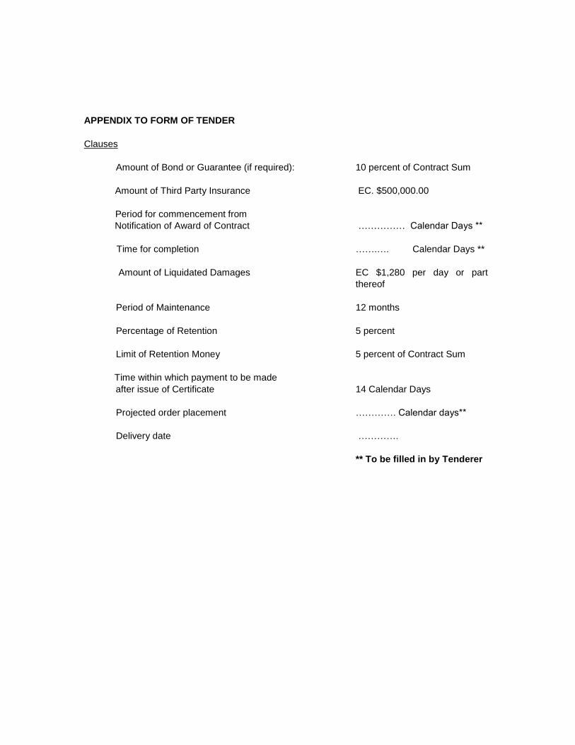
APPENDIX TO FORM OF TENDER
Clauses
Amount of Bond or Guarantee (if required):
10 percent of Contract Sum
Amount of Third Party Insurance
Period for commencement from
EC. $500,000.00
Notification of Award of Contract
…………… Calendar Days **
Time for completion
…….…. Calendar Days **
Amount of Liquidated Damages
EC $1,280 per day or part
thereof
Period of Maintenance
12 months
Percentage of Retention
5 percent
Limit of Retention Money
Time within which payment to be made
5 percent of Contract Sum
after issue of Certificate
Projected order placement
14 Calendar Days
…………. Calendar days**
Delivery date
………….
** To be filled in by Tenderer
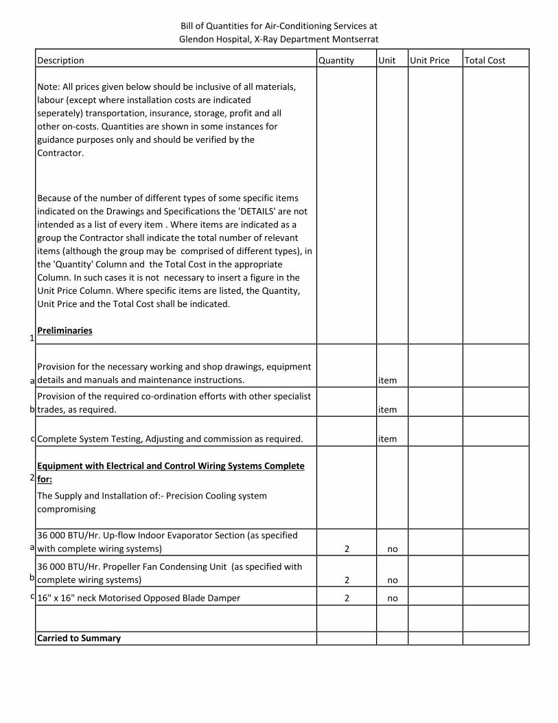
Bill of Quantities for Air-Conditioning Services at
Glendon Hospital, X-Ray Department Montserrat
Description Quantity Unit Unit Price Total Cost
Note: All prices given below should be inclusive of all materials,
labour (except where installation costs are indicated
seperately) transportation, insurance, storage, profit and all
other on-costs. Quantities are shown in some instances for
guidance purposes only and should be verified by the
Contractor.
Because of the number of different types of some specific items
indicated on the Drawings and Specifications the 'DETAILS' are not
intended as a list of every item . Where items are indicated as a
group the Contractor shall indicate the total number of relevant
items (although the group may be comprised of different types), in
the 'Quantity' Column and the Total Cost in the appropriate
Column. In such cases it is not necessary to insert a figure in the
Unit Price Column. Where specific items are listed, the Quantity,
Unit Price and the Total Cost shall be indicated.
Preliminaries
Provision for the necessary working and shop drawings, equipment
details and manuals and maintenance instructions.
item
Provision of the required co-ordination efforts with other specialist
trades, as required.
item
Complete System Testing, Adjusting and commission as required.
item
Equipment with Electrical and Control Wiring Systems Complete
for:
The Supply and Installation of:- Precision Cooling system
compromising
36 000 BTU/Hr. Up-flow Indoor Evaporator Section (as specified
with complete wiring systems)
2
no
36 000 BTU/Hr. Propeller Fan Condensing Unit (as specified with
complete wiring systems)
2
no
16" x 16" neck Motorised Opposed Blade Damper
2
no
Carried to Summary
1
a
b
c
2
a
b
c
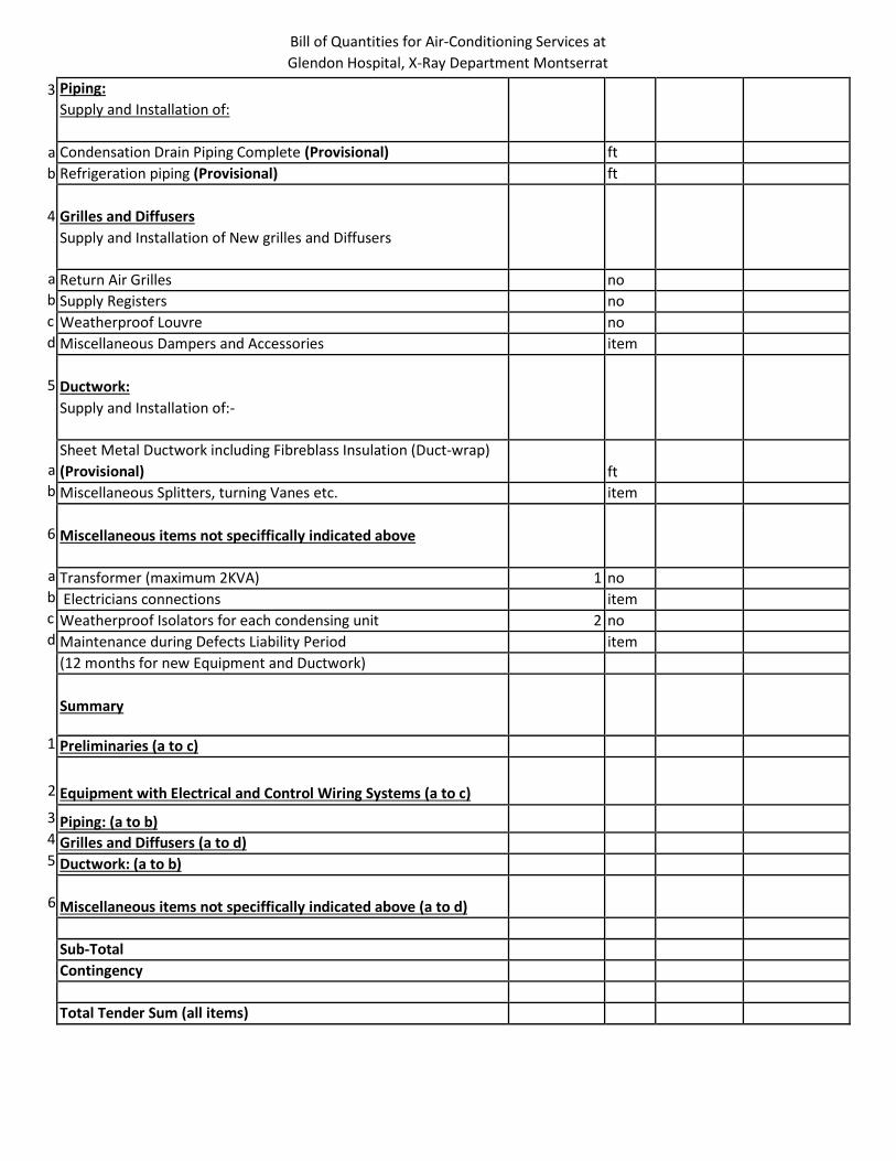
Bill of Quantities for Air-Conditioning Services at
Glendon Hospital, X-Ray Department Montserrat
Piping:
Supply and Installation of:
Condensation Drain Piping Complete (Provisional) ft
Refrigeration piping (Provisional) ft
Grilles and Diffusers
Supply and Installation of New grilles and Diffusers
Return Air Grilles no
Supply Registers no
Weatherproof Louvre no
Miscellaneous Dampers and Accessories item
Ductwork:
Supply and Installation of:-
Sheet Metal Ductwork including Fibreblass Insulation (Duct-wrap)
(Provisional)
ft
Miscellaneous Splitters, turning Vanes etc. item
Miscellaneous items not speciffically indicated above
Transformer (maximum 2KVA) 1 no
Electricians connections item
Weatherproof Isolators for each condensing unit 2 no
Maintenance during Defects Liability Period item
(12 months for new Equipment and Ductwork)
Summary
Preliminaries (a to c)
Equipment with Electrical and Control Wiring Systems (a to c)
Piping: (a to b)
Grilles and Diffusers (a to d)
Ductwork: (a to b)
Miscellaneous items not speciffically indicated above (a to d)
Sub-Total
Contingency
Total Tender Sum (all items)
3
a
b
4
a
b
c
d
5
a
b
6
a
b
c
d
1
2
3
4
5
6

TECHNICAL SPECIFICATIONS
FOR THE
AIR-CONDITIONING SERVICES
FOR
GLENDON HOSPITAL
X-RAY DEPARTMENT
MONTSERRAT
WEST INDIES
October 2017
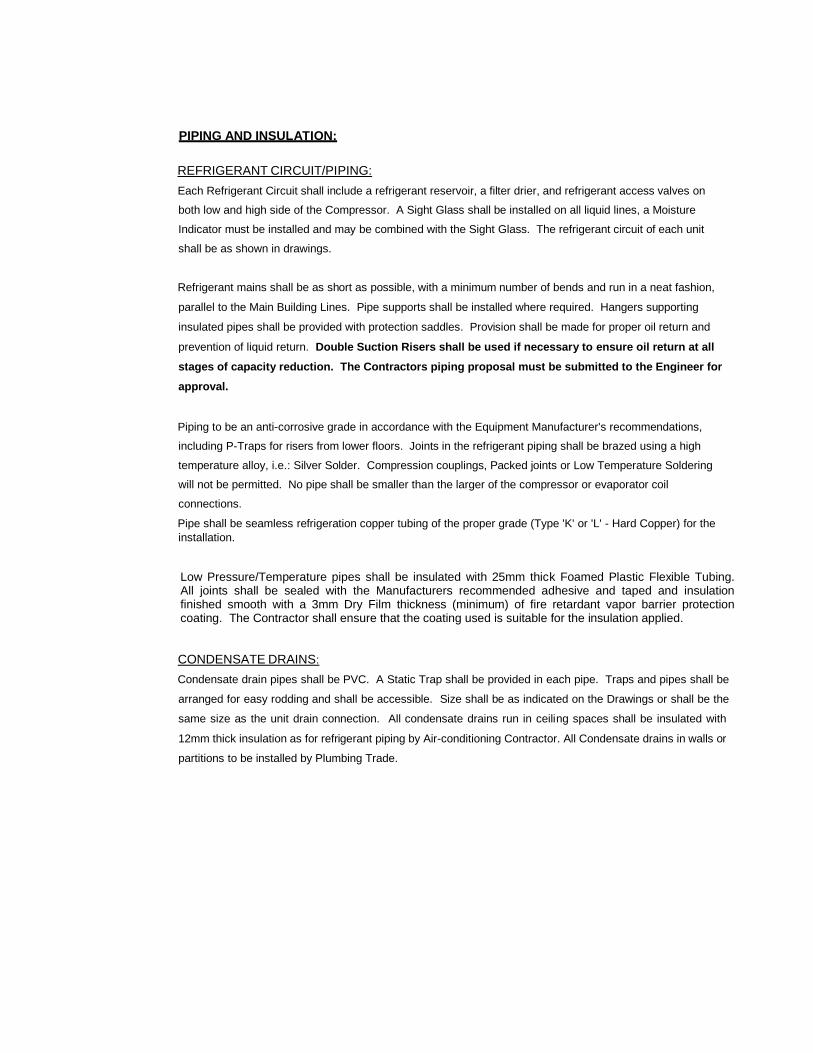
PIPING AND INSULATION:
REFRIGERANT CIRCUIT/PIPING:
Each Refrigerant Circuit shall include a refrigerant reservoir, a filter drier, and refrigerant access valves on
both low and high side of the Compressor. A Sight Glass shall be installed on all liquid lines, a Moisture
Indicator must be installed and may be combined with the Sight Glass. The refrigerant circuit of each unit
shall be as shown in drawings.
Refrigerant mains shall be as short as possible, with a minimum number of bends and run in a neat fashion,
parallel to the Main Building Lines. Pipe supports shall be installed where required. Hangers supporting
insulated pipes shall be provided with protection saddles. Provision shall be made for proper oil return and
prevention of liquid return. Double Suction Risers shall be used if necessary to ensure oil return at all
stages of capacity reduction. The Contractors piping proposal must be submitted to the Engineer for
approval.
Piping to be an anti-corrosive grade in accordance with the Equipment Manufacturer's recommendations,
including P-Traps for risers from lower floors. Joints in the refrigerant piping shall be brazed using a high
temperature alloy, i.e.: Silver Solder. Compression couplings, Packed joints or Low Temperature Soldering
will not be permitted. No pipe shall be smaller than the larger of the compressor or evaporator coil
connections.
Pipe shall be seamless refrigeration copper tubing of the proper grade (Type 'K' or 'L' - Hard Copper) for the
installation.
Low Pressure/Temperature pipes shall be insulated with 25mm thick Foamed Plastic Flexible Tubing. All joints shall be sealed with the Manufacturers recommended adhesive and taped and insulation finished smooth with a 3mm Dry Film thickness (minimum) of fire retardant vapor barrier protection coating. The Contractor shall ensure that the coating used is suitable for the insulation applied.
CONDENSATE DRAINS:
Condensate drain pipes shall be PVC. A Static Trap shall be provided in each pipe. Traps and pipes shall be
arranged for easy rodding and shall be accessible. Size shall be as indicated on the Drawings or shall be the
same size as the unit drain connection. All condensate drains run in ceiling spaces shall be insulated with
12mm thick insulation as for refrigerant piping by Air-conditioning Contractor. All Condensate drains in walls or
partitions to be installed by Plumbing Trade.
NOISE AND VIBRATION CONTROL:
GENERAL:
The Contractor shall ensure that all equipment is adequately isolated and that acceptable noise levels exist in
the occupied areas (ASHRAE GUIDE AVERAGE NC LEVELS).
Noise measurements shall be made at a distance of not less than 2M from the Equipment, Duct or Terminal
Device. If required, the Manufacturer's Representative, through this Contractor, shall make
recommendations covering any necessary alterations required, in order that the design criteria be obtained.
VIBRATION ISOLATION - APPLICATIONS:
All concrete foundations, pads and supports shall be furnished and installed in accordance with Shop
Drawings and Details. This Contractor shall furnish and set all anchor bolts and all vibration isolating devices
as well as do all final grouting.
All structural steel and pipe supports for equipment piping, etc., shall be furnished and installed by this
Contractor.
All floor mounted equipment shall be erected on 100mm high concrete pads over the complete floor area of
the equipment unless specified to the contrary herein.
Furnish and install all necessary supports for equipment furnished under this Contract. To meet the varying
conditions in each case, these supports shall consist of pipe stands, steel angle or strap hangers, saddles,
brackets, etc. as shown or approved.
All wiring and other connections to vibration isolated equipment shall be made flexible with a minimum 1800
loop of flexible conduit in order to avoid restraining the equipment and short circuiting the vibration isolators.
Unless otherwise indicated on the Drawings all equipment mounted on vibration isolator bases shall have a
minimum operating clearance of 25mm between the base and the floor or housekeeping pad beneath.
Clearance space shall be checked to ensure that no scrap rubbish, hardware, etc. has been left to possibly
short circuit the isolated base.
DUCTWORK:
LOW VELOCITY SHEET METAL DUCTWORK:
Where specified, ductwork shall be in accordance with the 'LOW VELOCITY AND DUCT CONSTRUCTION
STANDARDS" issued by the Sheet Metal and Air-Conditioning Contractors National Association, P.O. Box
3506, Washington D.C. 2007, U.S.A., hereinafter referred to as 'L0W VELOCITY STANDARDS.'
Ductwork, unless specifically noted otherwise shall be prime galvanized. Galvanizing shall be carefully done
and the sheets shall be of such quality that they may be bent flat on themselves with no fracture to coating or
base metal.
NOTE: ALL Joints and Seams in all sheet metal ductwork shall be sealed with an approved high
pressure odorless, solvent-free fast curing elastomeric duct sealant.
If sheets are used which are manufactured in a system of sizing other than U.S. Standard Gauge, the
thickness used in each case shall be equal to or greater than the thickness of the U.S Standard Gauge
stated.
All laps shall be in the direction of air flow. No sheet metal screws shall be used in the duct where it is
possible to use rivets or bolts. All edges and clips shall be hammered down as to leave smooth finished
surface inside the ducts and sealed with high pressure duct sealer. Allowable duct leakage will be limited to
5% (Maximum) of the total CFM handled. Duct leakage shall be the difference between the measured CFM
at supply air diffusers and registers.
All ducts shall be protected during fabrication and erection to prevent dirt and debris from entering.
All sheet metal panels 300mm (12") and larger which are not insulated either inside or outside shall be cross -
broken.
All sheet metal tees, bends or elbows shall be made with a centre-line radius of not less than the width of the
duct where space conditions permit.
Where shown on the Drawings square elbows shall be used with double thickness turning vanes.
Transforming sections shall have maximum slope 1 in 7 for High Velocity and 1 in 4 for Low Velocity Ducts.
Flexible connections shall be used at outlets from air-handling equipment and where shown on the Drawings
shall be UL Approved Duro-Dyne 'DUROLON' approximately 150mm (6") long. At least 25mm (1") slack shall
be allowed in these connections to ensure that no Vibrations are transmitted from equipment to ductwork.
Flexible connectors shall be in pre-fabricated form with two strips of 75mm (3") 24-gauge galvanized metal
firmly attached to each end of fabric.
Install 1" thick fiberglass duct-board over flexible connectors.
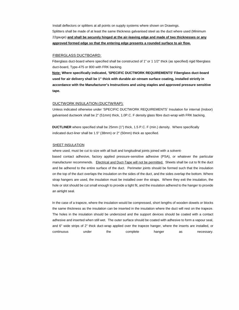
Install deflectors or splitters at all points on supply systems where shown on Drawings.
Splitters shall be made of at least the same thickness galvanised steel as the duct where used (Minimum
22gauge) and shall be securely hinged at the air-leaving edge and made of two thicknesses or any
approved formed edge so that the entering edge presents a rounded surface to air flow.
FIBERGLASS DUCTBOARD:
Fiberglass duct-board where specified shall be constructed of 1" or 1 1/2" thick (as specified) rigid fiberglass
duct-board, Type-475 or 800 with FRK backing.
Note: Where specifically indicated, 'SPECIFIC DUCTWORK REQUIREMENTS' Fiberglass duct-board
used for air delivery shall be 1" thick with durable air-stream surface coating, installed strictly in
accordance with the Manufacturer’s Instructions and using staples and approved pressure sensitive
tape.
DUCTWORK INSULATION (DUCTWRAP):
Unless indicated otherwise under ‘SPECIFIC DUCTWORK REQUIREMENTS’ Insulation for internal (Indoor)
galvanised ductwork shall be 2" (51mm) thick, 1.0P.C. F density glass fibre duct-wrap with FRK backing.
DUCTLINER where specified shall be 25mm (1") thick, 1.5 P.C. F (min.) density. Where specifically
indicated duct-liner shall be 1.5" (38mm) or 2" (50mm) thick as specified.
SHEET INSULATION
where used, must be cut to size with all butt and longitudinal joints joined with a solvent-
based contact adhesive, factory applied pressure-sensitive adhesive (PSA), or whatever the particular
manufacturer recommends. Electrical and Duct-Tape will not be permitted. Sheets shall be cut to fit the duct
and be adhered to the entire surface of the duct. Perimeter joints should be formed such that the insulation
on the top of the duct overlaps the insulation on the sides of the duct, and the sides overlap the bottom. Where
strap hangers are used, the insulation must be installed over the straps. Where they exit the insulation, the
hole or slot should be cut small enough to provide a tight fit, and the insulation adhered to the hanger to provide
an airtight seal.
In the case of a trapeze, where the insulation would be compressed, short lengths of wooden dowels or blocks
the same thickness as the insulation can be inserted in the insulation where the duct will rest on the trapeze.
The holes in the insulation should be undersized and the support devices should be coated with a contact
adhesive and inserted when still wet. The outer surface should be coated with adhesive to form a vapour seal,
and 6" wide strips of 2" thick duct-wrap applied over the trapeze hanger, where the inserts are installed, or
continuous under the complete hanger as necessary.
2
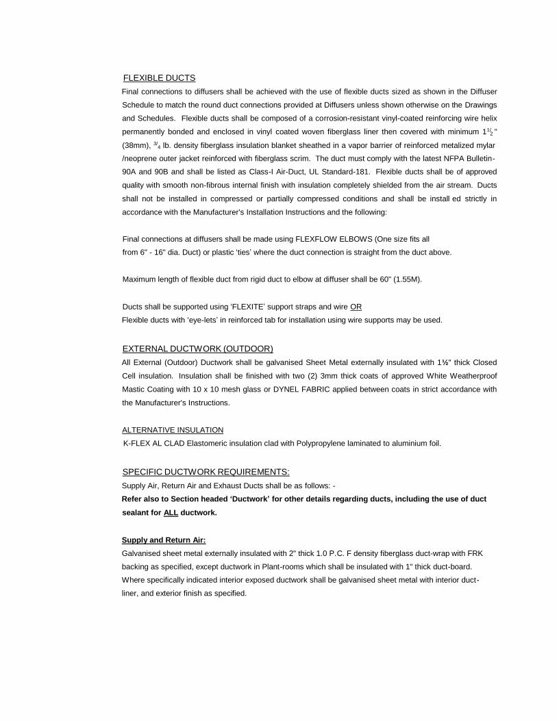
FLEXIBLE DUCTS
Final connections to diffusers shall be achieved with the use of flexible ducts sized as shown in the Diffuser
Schedule to match the round duct connections provided at Diffusers unless shown otherwise on the Drawings
and Schedules. Flexible ducts shall be composed of a corrosion-resistant vinyl-coated reinforcing wire helix
permanently bonded and enclosed in vinyl coated woven fiberglass liner then covered with minimum 11/ "
(38mm), 3/4 lb. density fiberglass insulation blanket sheathed in a vapor barrier of reinforced metalized mylar
/neoprene outer jacket reinforced with fiberglass scrim. The duct must comply with the latest NFPA Bulletin-
90A and 90B and shall be listed as Class-I Air-Duct, UL Standard-181. Flexible ducts shall be of approved
quality with smooth non-fibrous internal finish with insulation completely shielded from the air stream. Ducts
shall not be installed in compressed or partially compressed conditions and shall be install ed strictly in
accordance with the Manufacturer's Installation Instructions and the following:
Final connections at diffusers shall be made using FLEXFLOW ELBOWS (One size fits all
from 6" - 16" dia. Duct) or plastic ‘ties’ where the duct connection is straight from the duct above.
Maximum length of flexible duct from rigid duct to elbow at diffuser shall be 60" (1.55M).
Ducts shall be supported using ‘FLEXITE’ support straps and wire OR
Flexible ducts with ‘eye-lets’ in reinforced tab for installation using wire supports may be used.
EXTERNAL DUCTWORK (OUTDOOR)
All External (Outdoor) Ductwork shall be galvanised Sheet Metal externally insulated with 1½" thick Closed
Cell insulation. Insulation shall be finished with two (2) 3mm thick coats of approved White Weatherproof
Mastic Coating with 10 x 10 mesh glass or DYNEL FABRIC applied between coats in strict accordance with
the Manufacturer's Instructions.
ALTERNATIVE INSULATION
K-FLEX AL CLAD Elastomeric insulation clad with Polypropylene laminated to aluminium foil.
SPECIFIC DUCTWORK REQUIREMENTS:
Supply Air, Return Air and Exhaust Ducts shall be as follows: -
Refer also to Section headed ‘Ductwork’ for other details regarding ducts, including the use of duct
sealant for ALL ductwork.
Supply and Return Air:
Galvanised sheet metal externally insulated with 2" thick 1.0 P.C. F density fiberglass duct-wrap with FRK
backing as specified, except ductwork in Plant-rooms which shall be insulated with 1" thick duct-board.
Where specifically indicated interior exposed ductwork shall be galvanised sheet metal with interior duct -
liner, and exterior finish as specified.
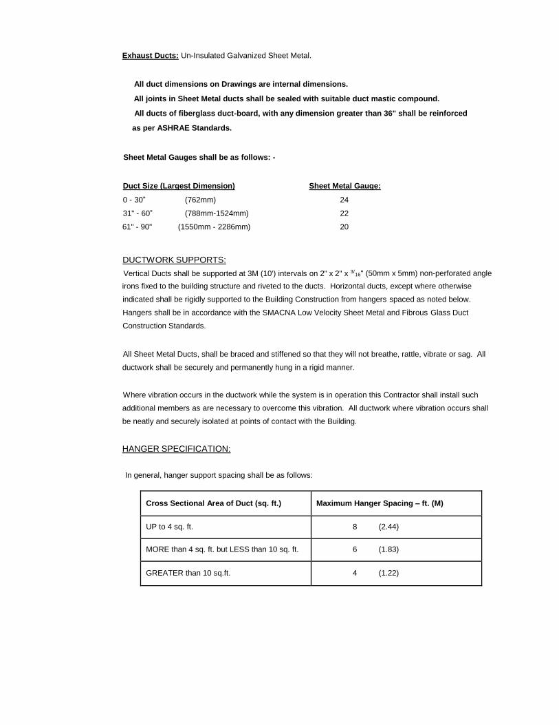
Exhaust Ducts: Un-Insulated Galvanized Sheet Metal.
All duct dimensions on Drawings are internal dimensions.
All joints in Sheet Metal ducts shall be sealed with suitable duct mastic compound.
All ducts of fiberglass duct-board, with any dimension greater than 36" shall be reinforced
as per ASHRAE Standards.
Sheet Metal Gauges shall be as follows: -
Duct Size (Largest Dimension) Sheet Metal Gauge:
0 - 30” (762mm) 24
31" - 60” (788mm-1524mm) 22
61" - 90" (1550mm - 2286mm) 20
DUCTWORK SUPPORTS:
Vertical Ducts shall be supported at 3M (10') intervals on 2" x 2" x 3/
" (50mm x 5mm) non-perforated angle16
irons fixed to the building structure and riveted to the ducts. Horizontal ducts, except where otherwise
indicated shall be rigidly supported to the Building Construction from hangers spaced as noted below.
Hangers shall be in accordance with the SMACNA Low Velocity Sheet Metal and Fibrous Glass Duct
Construction Standards.
All Sheet Metal Ducts, shall be braced and stiffened so that they will not breathe, rattle, vibrate or sag. All
ductwork shall be securely and permanently hung in a rigid manner.
Where vibration occurs in the ductwork while the system is in operation this Contractor shall install such
additional members as are necessary to overcome this vibration. All ductwork where vibration occurs shall
be neatly and securely isolated at points of contact with the Building.
HANGER SPECIFICATION:
In general, hanger support spacing shall be as follows:
Cross Sectional Area of Duct (sq. ft.)
Maximum Hanger Spacing – ft. (M)
UP to 4 sq. ft.
8 (2.44)
MORE than 4 sq. ft. but LESS than 10 sq. ft.
6 (1.83)
GREATER than 10 sq.ft.
4 (1.22)
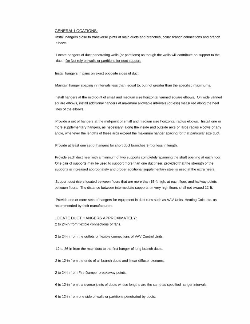
GENERAL LOCATIONS:
Install hangers close to transverse joints of main ducts and branches, collar branch connections and branch
elbows.
Locate hangers of duct penetrating walls (or partitions) as though the walls will contribute no support to the
duct. Do Not rely on walls or partitions for duct support.
Install hangers in pairs on exact opposite sides of duct.
Maintain hanger spacing in intervals less than, equal to, but not greater than the specified maximums.
Install hangers at the mid-point of small and medium size horizontal vanned square elbows. On wide vanned
square elbows, install additional hangers at maximum allowable intervals (or less) measured along the heel
lines of the elbows.
Provide a set of hangers at the mid-point of small and medium size horizontal radius elbows. Install one or
more supplementary hangers, as necessary, along the inside and outside arcs of large radius elbows of any
angle, whenever the lengths of these arcs exceed the maximum hanger spacing for that particular size duct.
Provide at least one set of hangers for short duct branches 3-ft or less in length.
Provide each duct riser with a minimum of two supports completely spanning the shaft opening at each floor.
One pair of supports may be used to support more than one duct riser, provided that the strength of the
supports is increased appropriately and proper additional supplementary steel is used at the extra risers.
Support duct risers located between floors that are more than 15-ft high, at each floor, and halfway points
between floors. The distance between intermediate supports on very high floors shall not exceed 12-ft.
Provide one or more sets of hangers for equipment in duct runs such as VAV Units, Heating Coils etc. as
recommended by their manufacturers.
LOCATE DUCT HANGERS APPROXIMATELY:
2 to 24-in from flexible connections of fans.
2 to 24-in from the outlets or flexible connections of VAV Control Units.
12 to 36-in from the main duct to the first hanger of long branch ducts.
2 to 12-in from the ends of all branch ducts and linear diffuser plenums.
2 to 24-in from Fire Damper breakaway points.
6 to 12-in from transverse joints of ducts whose lengths are the same as specified hanger intervals.
6 to 12-in from one side of walls or partitions penetrated by ducts.
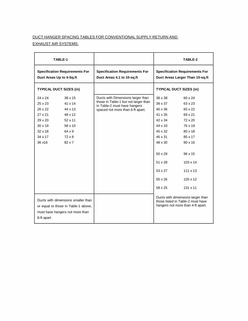
DUCT HANGER SPACING TABLES FOR CONVENTIONAL SUPPLY RETURN AND
EXHAUST AIR SYSTEMS:
TABLE-1
TABLE-2
Specification Requirements For
Duct Areas Up to 4-Sq.ft
Specification Requirements For
Duct Areas 4.1 to 10-sq.ft
Specification Requirements For
Duct Areas Larger Than 10-sq.ft
TYPICAL DUCT SIZES (in)
TYPICAL DUCT SIZES (in)
24 x 24 38 x 15
25 x 23 41 x 14
26 x 22 44 x 13
27 x 21 48 x 12
29 x 20 52 x 11
30 x 19 58 x 10
32 x 18 64 x 9
34 x 17 72 x 8
36 x16 82 x 7
Ducts with Dimensions larger than those in Table-1 but not larger than in Table-2 must have hangers spaced not more than 6-ft apart.
38 x 38 60 x 24
39 x 37 63 x 23
40 x 36 65 x 22
41 x 35 69 x 21
42 x 34 72 x 20
44 x 33 76 x 19
45 x 32 80 x 18
46 x 31 85 x 17
48 x 30 90 x 16
50 x 29 96 x 15
51 x 28 103 x 14
53 x 27 111 x 13
55 x 26 120 x 12
58 x 25 131 x 11
Ducts with dimensions smaller than
or equal to those in Table-1 above,
must have hangers not more than
8-ft apart
Ducts with dimensions larger than those listed in Table-2 must have hangers not more than 4-ft apart.

DIFFUSERS, REGISTERS, GRILLES:
Supply and Install Grilles, Registers and Diffusers as listed in the 'GRILLE, REGISTER, DIFFUSER
SCHEDULE' where shown and as arranged on the Drawings.
Diffusers, Registers and Grilles shall be factory fabricated corrosion-resistant aluminium with finish as
indicated in the Schedule.
SUPPLY AND EXHAUST FANS:
Exhaust Fans shall be as indicated in the Drawings and Schedule and Motors shall have inheren t overload
protection. Control of fans shall be as indicated on the Drawings.
ELECTRICS, CONTROLS AND SAFETIES:
. MOTORS:
All apparatus supplied by this Contractor shall be complete with Electric Motors, necessary Drives, Guards
and Starting Equipment.
The Employer reserve the right to reject any motor which is too noisy for the application, produces
excessive vibration or operates with power factor of efficiency below specified standard and Manufacturer's
Performance Data.
All motors shall be manufactured and installed in accordance with NEMA Standards for 400C temperature
rise. All motors, unless noted otherwise shall be high efficiency type, designed for hard continuous service,
suitable for operation with driven device, free from excessive and un-necessary vibration.
Each motor shall have adequate capacity to operate the associated driven device under all conditions of load
and service without overloading and be at least of the HP specified. No motor, unless noted otherwise shall
operate in excess of 1500-RPM. Each motor shall be provided with a conduit terminal box in approved
location.
ELECTRICAL SUPPLY:
The available electrical supply is 460/230-Volts/3-Phase/4-Wire/50-Hertz and all equipment must be able to
operate satisfactorily at voltages within + 8.5% of this nominal voltage. Supply and install transformer capable
of carrying loads as mentioned above including all connections.
STARTERS AND ISOLATORS:
ENCLOSURE : Indoor - General Purpose NEMA-I.
: Others - NEMA Type 3R Outdoor Rain-Tight.
TYPE : Magnetic Across-the-Line.
OVERLOADS : Ambient temperature compensated thermal
overloads on all phases.
CONTROLS : As indicated on the Drawings and in these
Specifications.
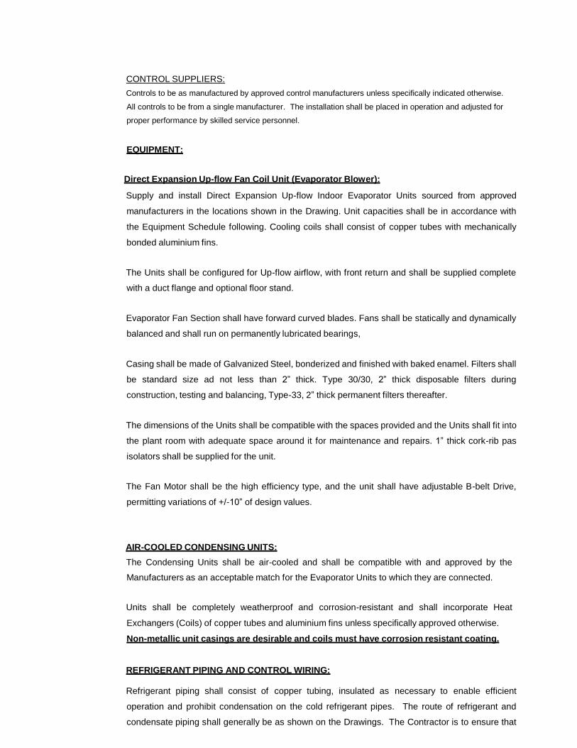
CONTROL SUPPLIERS:
Controls to be as manufactured by approved control manufacturers unless specifically indicated otherwise.
All controls to be from a single manufacturer. The installation shall be placed in operation and adjusted for
proper performance by skilled service personnel.
EQUIPMENT:
Direct Expansion Up-flow Fan Coil Unit (Evaporator Blower):
Supply and install Direct Expansion Up-flow Indoor Evaporator Units sourced from approved
manufacturers in the locations shown in the Drawing. Unit capacities shall be in accordance with
the Equipment Schedule following. Cooling coils shall consist of copper tubes with mechanically
bonded aluminium fins.
The Units shall be configured for Up-flow airflow, with front return and shall be supplied complete
with a duct flange and optional floor stand.
Evaporator Fan Section shall have forward curved blades. Fans shall be statically and dynamically
balanced and shall run on permanently lubricated bearings,
Casing shall be made of Galvanized Steel, bonderized and finished with baked enamel. Filters shall
be standard size ad not less than 2” thick. Type 30/30, 2” thick disposable filters during
construction, testing and balancing, Type-33, 2” thick permanent filters thereafter.
The dimensions of the Units shall be compatible with the spaces provided and the Units shall fit into
the plant room with adequate space around it for maintenance and repairs. 1” thick cork-rib pas
isolators shall be supplied for the unit.
The Fan Motor shall be the high efficiency type, and the unit shall have adjustable B-belt Drive,
permitting variations of +/-10” of design values.
AIR-COOLED CONDENSING UNITS:
The Condensing Units shall be air-cooled and shall be compatible with and approved by the
Manufacturers as an acceptable match for the Evaporator Units to which they are connected.
Units shall be completely weatherproof and corrosion-resistant and shall incorporate Heat
Exchangers (Coils) of copper tubes and aluminium fins unless specifically approved otherwise.
Non-metallic unit casings are desirable and coils must have corrosion resistant coating.
REFRIGERANT PIPING AND CONTROL WIRING:
Refrigerant piping shall consist of copper tubing, insulated as necessary to enable efficient
operation and prohibit condensation on the cold refrigerant pipes. The route of refrigerant and
condensate piping shall generally be as shown on the Drawings. The Contractor is to ensure that
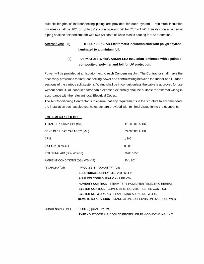
suitable lengths of interconnecting piping are provided for each system. Minimum insulation
thickness shall be 1/2” for up to ¾” suction pipe and ¾” for 7/8” – 1 ¼’. Insulation on all external
piping shall be finished smooth with two (2) coats of white mastic coating for UV protection.
Alternatives: (i) K-FLEX AL CLAD Elastomeric insulation clad with polypropylene
laminated to aluminium foil.
(ii) ‘ARMATUFF White’, ARMAFLEX Insulation laminated with a painted
composite of polymer and foil for UV protection.
Power will be provided at an Isolator next to each Condensing Unit. The Contractor shall make the
necessary provisions for inter-connecting power and control wiring between the Indoor and Outdoor
sections of the various split systems. Wiring shall be in conduit unless the cable is approved for use
without conduit. All conduit and/or cable exposed externally shall be suitable for external wiring in
accordance with the relevant local Electrical Codes.
The Air-Conditioning Contractor is to ensure that any requirements in the structure to accommodate
the installation such as sleeves, holes etc. are provided with minimal disruption to the occupants.
EQUIPMENT SCHEDULE
TOTAL HEAT CAPCITY (Min) 41 000 BTU / HR
SENSIBLE HEAT CAPACITY (Min) 33 000 BTU / HR
CFM 1 800
EXT S.P (In. W.G.) 0.30”
ENTERING AIR (DB / WB (°F) 76.0° / 65°
AMBIENT CONDITIONS (DB / WB) (°F) 90° / 80°
EVAPORATOR - -PFCU-3-3-4 - (QUANTITY – 2#)
ELECTRICAL SUPPLY - 460 V /3 / 60 Hz
AIRFLOW CONFIGURATION - UPFLOW
HUMIDITY CONTROL - STEAM TYPE HUMIDFIER / ELECTRIC REHEAT
SYSTEM CONTROL - COMPU-AIRE INC. 2200+ SERIES CONTROL
SYSTEM NETWORKING - PLAN STAND ALONE NETWORK
REMOTE SUPERVISION - STAND ALONE SUPERVISION OVER PCO WEB
CONDENSING UNIT- PFCU - (QUANTITY– 2#)
TYPE - OUTDOOR AIR-COOLED PROPELLER FAN CONDENSING UNIT
ANTI-CORROSION TREATMENT - COIL AND CHASSIS (FACTORY APPLIED)
PIPING MATERIALS AND ASSEMBLY:
PIPE GENERAL:
In general, the various lines to be installed by the Contractor under this Specification shall be run as indicated
and as specified herein, as required by the particular conditions at the site, and as required to conform to the
generally accepted standards so as to complete the work in a neat and satisfactory workable manner. The
piping shown on the Drawings shall be considered as diagrammatic for clearness in indicating the general
run and connections and may or may not in all parts be shown in its true position. This does not relieve the
Contractor from responsibility for the proper erection of systems of piping in every respect suitable for the
work intended as described in the Specifications.
The following is a general outline concerning the running of various lines and type material and is to be
adhered to unless the drawings or conditions at the building site necessitate deviating from these standards.
All piping shall be installed with due regard to expansion and contraction; and the type of hanger
method of support, location of supports, etc. shall be governed in part by this consideration. Transmission of
vibration noise etc. shall also be considered and any special suspension with vibration dampeners required
to minimize transmission shall be used where necessary. In general, all hangers must be approved by
the Engineer before installation.
All piping shall be subject to inspection and testing by an approved Contractor and no covering shall be
applied until the pipe has been inspected and tested.
All piping shall be installed in accordance with the best practices of the trade, and shall be clear of
dirt before installation, flushed and left clean before service.
In erection, all piping shall be properly supported and provision shall be made for expansion,
contraction and anchoring of piping. The Contractor is to familiarize himself with the Hanger requirements for
the insulations of the systems.
During installation, keep plugged or capped all openings in pipes or fittings to keep out foreign matter.
Generally, all high points of the piping system shall be vented, and the system installed in such a manner
that the entire system can be drained. All low points shall have 20-mm drain cock with hose end installed.
Pipes shall be placed and installed so there will be no interference with the installation of Equipment, other
piping systems, ducts etc. or with future maintenance requirements. Pipes shall also be spaced to allow for
insulation specified.
Should leaks develop in various systems after they have been placed in operation, it shall be the
responsibility of the Contractor to repair same, and if damage occurs to the building structure, contents etc.
through these leaks this damage will be charged to the Contractor.
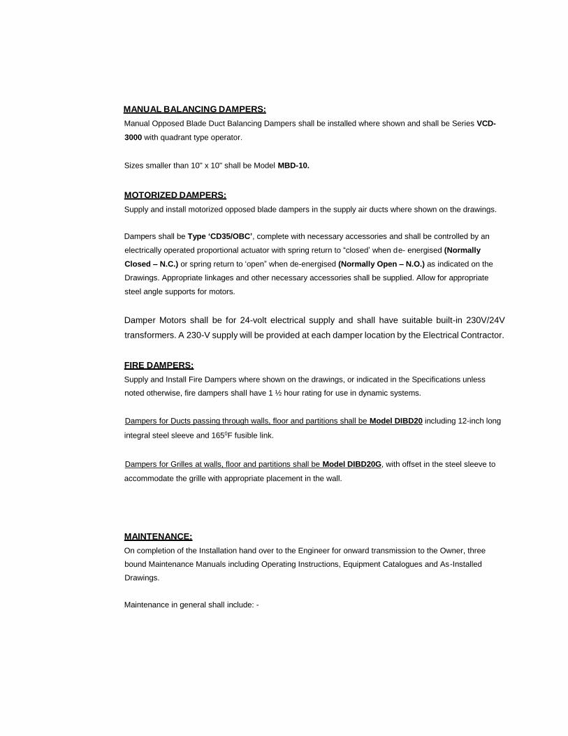
MANUAL BALANCING DAMPERS:
Manual Opposed Blade Duct Balancing Dampers shall be installed where shown and shall be Series VCD-
3000 with quadrant type operator.
Sizes smaller than 10" x 10" shall be Model MBD-10.
MOTORIZED DAMPERS:
Supply and install motorized opposed blade dampers in the supply air ducts where shown on the drawings.
Dampers shall be Type ‘CD35/OBC’, complete with necessary accessories and shall be controlled by an
electrically operated proportional actuator with spring return to “closed’ when d e- energised (Normally
Closed – N.C.) or spring return to ‘open” when de-energised (Normally Open – N.O.) as indicated on the
Drawings. Appropriate linkages and other necessary accessories shall be supplied. Allow for appropriate
steel angle supports for motors.
Damper Motors shall be for 24-volt electrical supply and shall have suitable built-in 230V/24V
transformers. A 230-V supply will be provided at each damper location by the Electrical Contractor.
FIRE DAMPERS:
Supply and Install Fire Dampers where shown on the drawings, or indicated in the Specifications unless
noted otherwise, fire dampers shall have 1 ½ hour rating for use in dynamic systems.
Dampers for Ducts passing through walls, floor and partitions shall be Model DIBD20 including 12-inch long
integral steel sleeve and 1650F fusible link.
Dampers for Grilles at walls, floor and partitions shall be Model DIBD20G, with offset in the steel sleeve to
accommodate the grille with appropriate placement in the wall.
MAINTENANCE:
On completion of the Installation hand over to the Engineer for onward transmission to the Owner, three
bound Maintenance Manuals including Operating Instructions, Equipment Catalogues and As-Installed
Drawings.
Maintenance in general shall include: -
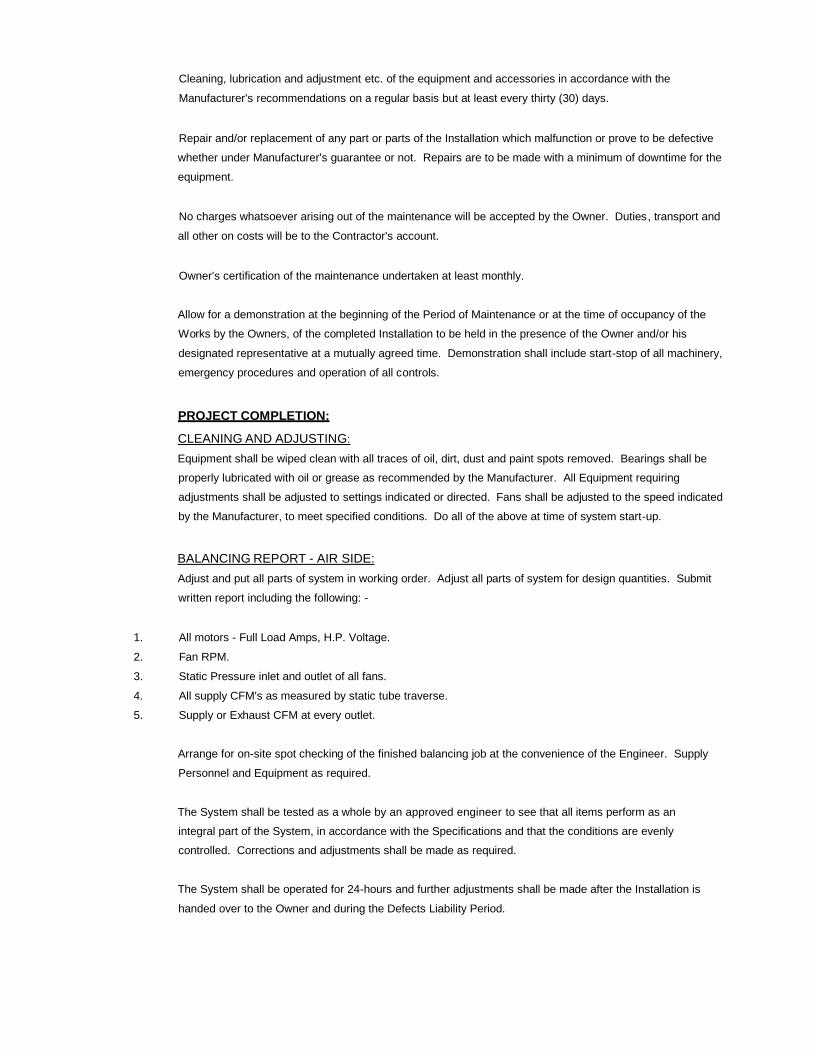
Cleaning, lubrication and adjustment etc. of the equipment and accessories in accordance with the
Manufacturer's recommendations on a regular basis but at least every thirty (30) days.
Repair and/or replacement of any part or parts of the Installation which malfunction or prove to be defective
whether under Manufacturer's guarantee or not. Repairs are to be made with a minimum of downtime for the
equipment.
No charges whatsoever arising out of the maintenance will be accepted by the Owner. Duties, transport and
all other on costs will be to the Contractor's account.
Owner's certification of the maintenance undertaken at least monthly.
Allow for a demonstration at the beginning of the Period of Maintenance or at the time of occupancy of the
Works by the Owners, of the completed Installation to be held in the presence of the Owner and/or his
designated representative at a mutually agreed time. Demonstration shall include start-stop of all machinery,
emergency procedures and operation of all controls.
PROJECT COMPLETION:
CLEANING AND ADJUSTING:
Equipment shall be wiped clean with all traces of oil, dirt, dust and paint spots removed. Bearings shall be
properly lubricated with oil or grease as recommended by the Manufacturer. All Equipment requiring
adjustments shall be adjusted to settings indicated or directed. Fans shall be adjusted to the speed indicated
by the Manufacturer, to meet specified conditions. Do all of the above at time of system start-up.
BALANCING REPORT - AIR SIDE:
Adjust and put all parts of system in working order. Adjust all parts of system for design quantities. Submit
written report including the following: -
1. All motors - Full Load Amps, H.P. Voltage.
2. Fan RPM.
3. Static Pressure inlet and outlet of all fans.
4. All supply CFM's as measured by static tube traverse.
5. Supply or Exhaust CFM at every outlet.
Arrange for on-site spot checking of the finished balancing job at the convenience of the Engineer. Supply
Personnel and Equipment as required.
The System shall be tested as a whole by an approved engineer to see that all items perform as an
integral part of the System, in accordance with the Specifications and that the conditions are evenly
controlled. Corrections and adjustments shall be made as required.
The System shall be operated for 24-hours and further adjustments shall be made after the Installation is
handed over to the Owner and during the Defects Liability Period.
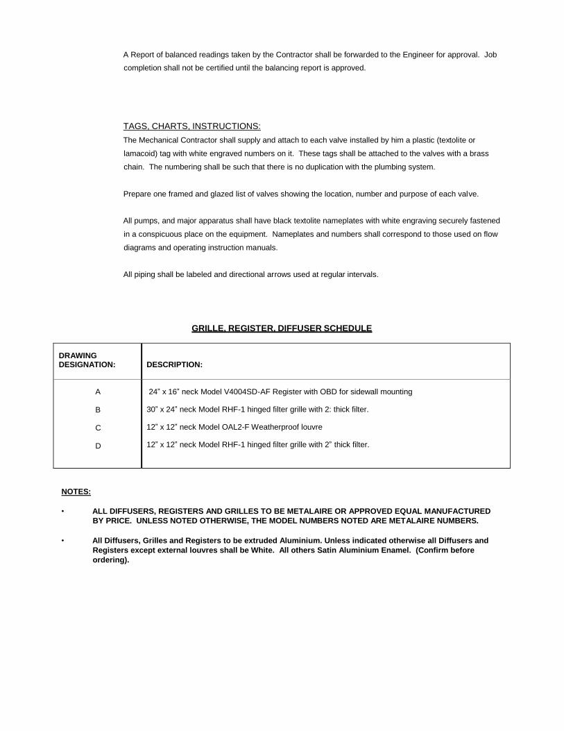
A Report of balanced readings taken by the Contractor shall be forwarded to the Engineer for approval. Job
completion shall not be certified until the balancing report is approved.
TAGS, CHARTS, INSTRUCTIONS:
The Mechanical Contractor shall supply and attach to each valve installed by him a plastic (textolite or
lamacoid) tag with white engraved numbers on it. These tags shall be attached to the valves with a brass
chain. The numbering shall be such that there is no duplication with the plumbing system.
Prepare one framed and glazed list of valves showing the location, number and purpose of each valve.
All pumps, and major apparatus shall have black textolite nameplates with white engraving securely fastened
in a conspicuous place on the equipment. Nameplates and numbers shall correspond to those used on flow
diagrams and operating instruction manuals.
All piping shall be labeled and directional arrows used at regular intervals.
GRILLE, REGISTER, DIFFUSER SCHEDULE
DRAWING DESIGNATION:
DESCRIPTION:
A
B
C
D
24” x 16” neck Model V4004SD-AF Register with OBD for sidewall mounting 30” x 24” neck Model RHF-1 hinged filter grille with 2: thick filter.
12” x 12” neck Model OAL2-F Weatherproof louvre
12” x 12” neck Model RHF-1 hinged filter grille with 2” thick filter.
NOTES:
• ALL DIFFUSERS, REGISTERS AND GRILLES TO BE METALAIRE OR APPROVED EQUAL MANUFACTURED
BY PRICE. UNLESS NOTED OTHERWISE, THE MODEL NUMBERS NOTED ARE METALAIRE NUMBERS.
• All Diffusers, Grilles and Registers to be extruded Aluminium. Unless indicated otherwise all Diffusers and
Registers except external louvres shall be White. All others Satin Aluminium Enamel. (Confirm before
ordering).


GOVERNMENT OF
MONTSERRAT
PUBLIC WORKS DEPARTMENT
GENERAL CONDITIONS
OF
CONTRACT
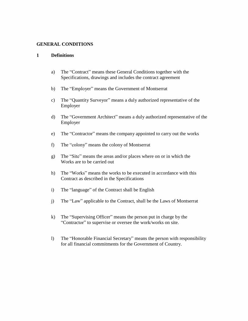
GENERAL CONDITIONS
1 Definitions
a) The “Contract” means these General Conditions together with the
Specifications, drawings and includes the contract agreement
b) The “Employer” means the Government of Montserrat
c) The “Quantity Surveyor” means a duly authorized representative of the
Employer
d) The “Government Architect” means a duly authorized representative of the
Employer
e) The “Contractor” means the company appointed to carry out the works
f) The “colony” means the colony of Montserrat
g) The “Site” means the areas and/or places where on or in which the
Works are to be carried out
h) The “Works” means the works to be executed in accordance with this
Contract as described in the Specifications
i) The “language” of the Contract shall be English
j) The “Law” applicable to the Contract, shall be the Laws of Montserrat
k) The “Supervising Officer” means the person put in charge by the
“Contractor” to supervise or oversee the work/works on site.
l) The “Honorable Financial Secretary” means the person with responsibility
for all financial commitments for the Government of Country.
2 Contract Document - Priority
1) Contract Agreement
2) Consultant Technical Specifications
3) Conditions of Contract
4) Consultant Drawings
5) Any other document forming part of the Contract
3 Extent of Contract
The Contract comprises the Supply, Delivery, Installation, Testing,
Commissioning and Maintenance of Precision Cooling AC systems complete for
the X-Ray room at the Glendon Hospital, and completion of all Works described
in the Consultants Limited Technical Specifications, Drawings and Tender
Documents. The works requires the Tenderer to supply all necessary labor,
materials, plant and temporary works to complete the described works together
with such materials as are required by the Technical Specifications.
4 Power to Vary or Omit
a) The Employer reserves the right to vary from time to time during the
progress of the works, the Specifications or Drawings and shall in writing,
notify the Contractor of such variation. If the instructions are given orally,
they shall, within two (2) days be confirmed in writing by the Quantity
Surveyor, in the event of any such variation involving an alteration in the
cost, or in the period required for completion an agreed revision of contract
price and/or time of completion may be made, any such alterations should
be deemed part of the Contract.
b) No variation, alteration or addition to the work indicated in the
Specification and/or Drawing shall be made unless the written instruction
of the employer has been obtained.
5 Assignment of Contract
c) Neither the Employer nor the Contractor shall without the consent of the
other assign this contract or any rights thereunder.
d) The Contractor shall not assign the whole or any part of the Works without
the consent of the Architect/ Contract Administrator. Such consent shall not
be unreasonably delayed or withheld but the Contractor shall remain wholly
responsible for carrying out and completing the Works in all respects in a
proper and workmanlike manner and in compliance with the Contract
Documents, and other Statutory Requirements. Notwithstanding any such
sub-contracting, the contractor shall give all notices required by the
Statutory Requirements and remain responsible to the Employer for the
Quality and execution of all of the works including any defaults and or
neglect of any sub-contractor or agent or workman employed by him.
6 Supply of Materials
1) The Contractor shall within the agreed contract price, supply such
materials as required (unless otherwise specified) and detailed in the Bill
of Quantities, on the drawings and by the Technical Specifications to
complete all of the works.
7 Setting Out
1) The Contractor shall be responsible for setting out of the work.
8 Workmanship
1. The Contractor shall not substitute any materials or goods so described
without the Project Architect/Contract Administrator consent, which shall
not be unreasonably delayed or withheld but shall not relieve the
Contractor of his other obligations. Where and to the extent that approval
of the quality of materials or goods or of the standards of workmanship is
a matter for the Project Architect/Contract Administrator opinion, such
quality and standards shall be to his reasonable satisfaction.
.2 To the extent that the quality of materials and goods or standards of
workmanship is neither described nor stated to be a matter for such opinion
or satisfaction they shall be of a standard appropriate to the works. The
Contractor shall upon the request of the Project Architect/ Contract
Administrator provide him with reasonable proof that the materials and
goods used comply with clause 6.1.
.3 The Employer may from time to time during the course of the Contract
inspect any completed or part-completed work of the Contractor. If the
Employer is not satisfied with such work, he shall in writing, inform the
Contractor of his dissatisfaction. Notwithstanding any such progress
inspection by the Project Architect/ Contract Administrator on
completion of the works, the Contractor shall satisfy the Employer as to
the quality and fitness of the work.
9 Removal of Debris
The Contractor shall remove all debris caused by their work from time to time as
it accumulates and shall leave the site clean on completion of the Contracted
Works.
10 Supervision of Works and Skilled Workmen
a) The Contractor shall provide all necessary superintendence during the
execution of the works. He shall ensure that at all times he has on the site a
competent person-in-charge and any instructions given to that person by
the Architect/ Contract Administrator shall be deemed to have been given
to the Contractor.
b) The Contractor shall employ in and about the execution of the Works only
such persons who are carefully skilled and experienced in their respective
several trades. Tenderers are to provide for special attendance to include
for the necessary costs in relation to the Employment of any Specialist
Trades required to carry out any works related to the successful completion
of the contract. This should include all travel, accommodation, and any
other expense and include for their return at the end of the contract.
c) The Supervising Officer may (but not unreasonably or vexatious) issue
instructions requiring the exclusion from the Works of any person
employed thereon.
11 Contractor’s Plant
The Contractor shall provide at their own cost all tools, and other plant
necessary for the purpose of carrying out the specified Work in an organized
and expeditious manner.
12 Payment Fees
The Contractor shall be responsible for the payment of all fees necessary for the
completion of the Contract required by a Statutory Authority within or without
the Colony.
13 Safety
a) The Contractor is responsible for the safety of all persons employed by
him.
b) He or she shall in no way carry out any work that could be seen to
endanger the life of any of his employees or of any member of the general
public, including any other employee of the employer.
c) He or she shall ensure that there is no communication between
him/herself, any member of the Hospital Staff in respect of the works.
d) He or she shall not abide by any instructions given by any member of
Hospital Staff for the entire contract period.
14 Liability of Contractor - personal injury or death
.1 The Contractor shall be liable for and shall, indemnify the Employer
Against, any expense, liability, loss, claim or proceedings whatsoever in
respect of personal injury to or death of any person arising out of or in the
course of or caused by the carrying out of the Works, except to the extent
that the same is due to any act or neglect of the Employer, of any of the
Employer’s Persons or of any Statutory Undertaker.
15 Liability of Contractor – injury or damage to property
.1 The Contractor shall be liable for, and shall indemnify the Employer
Against, any expense, liability, loss, claim or proceedings in respect of any
loss, injury or damage whatsoever to any property real or personal insofar
as such loss, injury or damage arises out of or in the course of or by reason
of the carrying out of the Works and to the extent that the same is due to
any negligence, breach of statutory duty, omission or default of the
Contractor or any of the Contractor’s Persons.
Injury or damage to property- Works and site materials excluded
.2 The reference to ‘property real or personal’ does not include the Works,
work executed and/or Site Materials up to and including whichever is the
earlier of:
.1 the date of issue of the Practical Completion Certificate; or
.2 the date of termination of the Contractor’s employment.
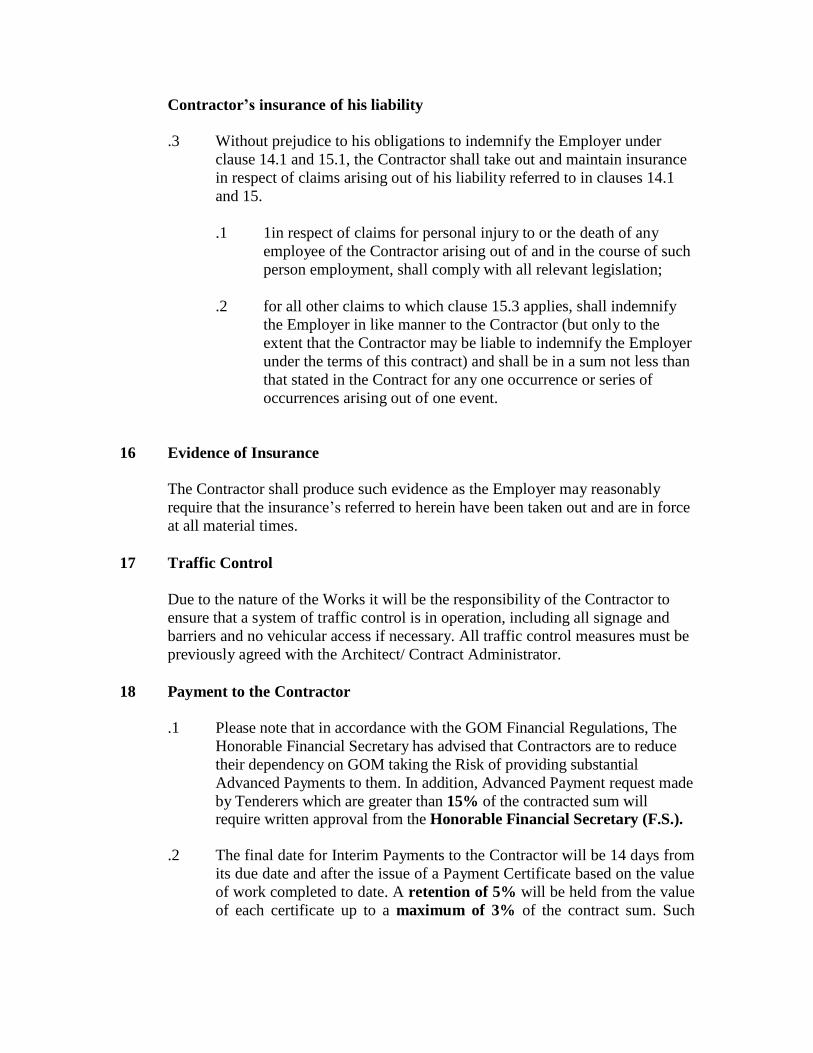
Contractor’s insurance of his liability
.3 Without prejudice to his obligations to indemnify the Employer under
clause 14.1 and 15.1, the Contractor shall take out and maintain insurance
in respect of claims arising out of his liability referred to in clauses 14.1
and 15.
.1 1in respect of claims for personal injury to or the death of any
employee of the Contractor arising out of and in the course of such
person employment, shall comply with all relevant legislation;
.2 for all other claims to which clause 15.3 applies, shall indemnify
the Employer in like manner to the Contractor (but only to the
extent that the Contractor may be liable to indemnify the Employer
under the terms of this contract) and shall be in a sum not less than
that stated in the Contract for any one occurrence or series of
occurrences arising out of one event.
16 Evidence of Insurance
The Contractor shall produce such evidence as the Employer may reasonably
require that the insurance’s referred to herein have been taken out and are in force
at all material times.
17 Traffic Control
Due to the nature of the Works it will be the responsibility of the Contractor to
ensure that a system of traffic control is in operation, including all signage and
barriers and no vehicular access if necessary. All traffic control measures must be
previously agreed with the Architect/ Contract Administrator.
18 Payment to the Contractor
.1 Please note that in accordance with the GOM Financial Regulations, The
Honorable Financial Secretary has advised that Contractors are to reduce
their dependency on GOM taking the Risk of providing substantial
Advanced Payments to them. In addition, Advanced Payment request made
by Tenderers which are greater than 15% of the contracted sum will require written approval from the Honorable Financial Secretary (F.S.).
.2 The final date for Interim Payments to the Contractor will be 14 days from
its due date and after the issue of a Payment Certificate based on the value
of work completed to date. A retention of 5% will be held from the value
of each certificate up to a maximum of 3% of the contract sum. Such
retention money will be released at the end of the warranty/rectification
period provided that all works have been completed to the satisfaction of
the Employer.
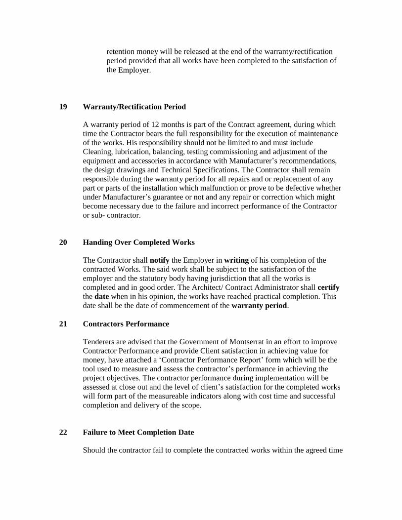
19 Warranty/Rectification Period
A warranty period of 12 months is part of the Contract agreement, during which
time the Contractor bears the full responsibility for the execution of maintenance
of the works. His responsibility should not be limited to and must include
Cleaning, lubrication, balancing, testing commissioning and adjustment of the
equipment and accessories in accordance with Manufacturer’s recommendations,
the design drawings and Technical Specifications. The Contractor shall remain
responsible during the warranty period for all repairs and or replacement of any
part or parts of the installation which malfunction or prove to be defective whether
under Manufacturer’s guarantee or not and any repair or correction which might
become necessary due to the failure and incorrect performance of the Contractor
or sub- contractor.
20 Handing Over Completed Works
The Contractor shall notify the Employer in writing of his completion of the
contracted Works. The said work shall be subject to the satisfaction of the
employer and the statutory body having jurisdiction that all the works is
completed and in good order. The Architect/ Contract Administrator shall certify
the date when in his opinion, the works have reached practical completion. This
date shall be the date of commencement of the warranty period.
21 Contractors Performance
Tenderers are advised that the Government of Montserrat in an effort to improve
Contractor Performance and provide Client satisfaction in achieving value for
money, have attached a ‘Contractor Performance Report’ form which will be the
tool used to measure and assess the contractor’s performance in achieving the
project objectives. The contractor performance during implementation will be
assessed at close out and the level of client’s satisfaction for the completed works
will form part of the measureable indicators along with cost time and successful
completion and delivery of the scope.
22 Failure to Meet Completion Date
Should the contractor fail to complete the contracted works within the agreed time

he shall be subject to a fine (Liquidated Damages of EC.$1,280 one thousand
two hundred and eighty dollars per day), for every day the completion is
overdue.
23 Matters not Contained in the Contract
Any matter not explicitly provided for within this Contract shall be in the matter
of a separate agreement between the Employer and Contractor. Any such
agreement shall be part of his Contract.
24 Matter of Disagreement/Resolution
If a dispute arises under this Contract, the parties agree that they would first
exhaust the provisions outlined in sections 46, 47 and 48 of the Public Finance
(Management and Accountability) Procurement regulations 2012. If the parties
fail to come to an amicable resolution through the provisions outlined above, then
the dispute shall be settled with the help of a mutually agreed-upon mediator in
Montserrat. The parties shall share any costs and fees equally, other than attorney
fees associated with the mediation equally.
25 Contract Documents
a) The Contractor shall receive two complete copies of Contract Documents
b) Subsequent to the commencement of the Contract, the Contractor shall receive a copy of all additions to and amendments to the Specifications or drawings.
26 Work not in accordance with the Contract
.1 If any work materials or goods are not in accordance with this Contract the
Project Architect/ Contract Administrator, may issue instructions in regard
to the removal from the site of all or any such work, materials or goods;
.2 after consultation with the Contractor and with the agreement of the
Employer, allow all or any of such work, materials or goods to remain
in which event he shall notify the Contractor to that effect but that shall not be construed as a variation and an appropriate deduction shall be made from the Contract Sum.
27 Workmanship not in accordance with the Contract
.1 Where there is any failure to comply with clause 8 in regard to the

carrying out of work in a proper and workmanlike manner the
Architect/Contract Administrator, in addition, may after consultation with
the Contractor, issue such instructions (whether requiring a Variation or
otherwise) as are necessary. To the extent that such instructions are
reasonable necessary, no addition shall be made to the Contract Sum and
no extension of time shall be given.
28 Contractor Performance Report
.1 It is a requirement of the Client for the Engineer to assess the performance
of the Contractor upon Final Certificate and final payment. The assessment
will be based on the following criteria;
i. The project deliverables achieved,
ii. Organization & management of works,
iii. Quality of work provided,
iv. Health & Safety plan implementation,
v. Management of Finances & budget,
vi. Technical performance & adherence to specifications,
vii. Completion time and scheduling.
.2 The assessment has an overall maximum score of 1 and the following are
the ratings that can be achieved;
1.00 – 0.75 = Very Good Performance
0.74 – 0.50 = Good Performance
0.49 – 0.25 = Poor Performance
0.24 – 0.00 = Very Poor Performance
.3 If Contractor has attained an overall score less than 0.50 at the end of the
contract performance reporting period, the Contractor will be subjected to
sanctions by procuring entities.
.4 Once a contractor has attained a first score of less than 0.50 which
indicated poor performance, he/she will be sanctioned and is only allowed
to bid on projects that has an estimated value EC$50,000 or less. This
sanction will be implemented for 12 months.
.5 If the Contractor has a second score on another project less than 0.50, the
Contractor will be suspended from being eligible to bid on any project
regardless of the value. This suspension and sanctions will run for 1 year.
.6 After a 1-year suspension or sanction, the Contractor will be allowed to bid

only on contracts valued at EC$ 50,000 or less. If on this occasion the
Contractor’s score is 0.75 or greater only then will he be allowed to bid on
contracts valued above EC$50,000. If his score is less than 0.75 but is equal
to or greater than 0.5, he will only be allowed to bid on contracts valued at $50,000 or less until he can achieve a higher score.
29 TERMINATION OF THE CONTRACT
1) Default by Contractor
If, before the date for practical completion of the works, the Contractor shall
make a default in any one or more of the following respects:
a) Without reasonable cause he wholly or substantially suspends the carrying out
of the works, or
b) He fails to proceed regularly or diligently with the works, or
c) He refuses or neglects to comply with a written instruction given by the
Government Architect and by such refusal or neglect the works are materially
affected The Government Architect may give to the Contractor a notice
specifying the default or defaults.
If the Contractor continues with the default for 14 days from the receipt of the
notice under the contract the Employer may by a further notice (delivered by hand
or sent by Recorded Signed for or Special Delivery post) to the Contractor
determine the employment of the Contractor under this Contract. Such
determination shall take effect on the date of receipt of such further relevant
notice.
A notice of termination shall not be given unreasonably or vexatiously.
2) Consequences of termination
The Employer may employ and pay other persons to carry out and complete the
works and he and they may enter and take possession of the site and the works
(subject to obtaining any necessary third party consents) may use all temporary
buildings, plant, tools, equipment and site materials for those purposes. The
Employer without prejudice to the contract may deduct the value of the completed
works from the total amount owed to the general contractor.
The Government Architect shall determine the amount due to the Contractor
which shall include loss, damage or expenses incurred by the Employer as a direct
consequence of the determination. A final payment certificate will be prepared
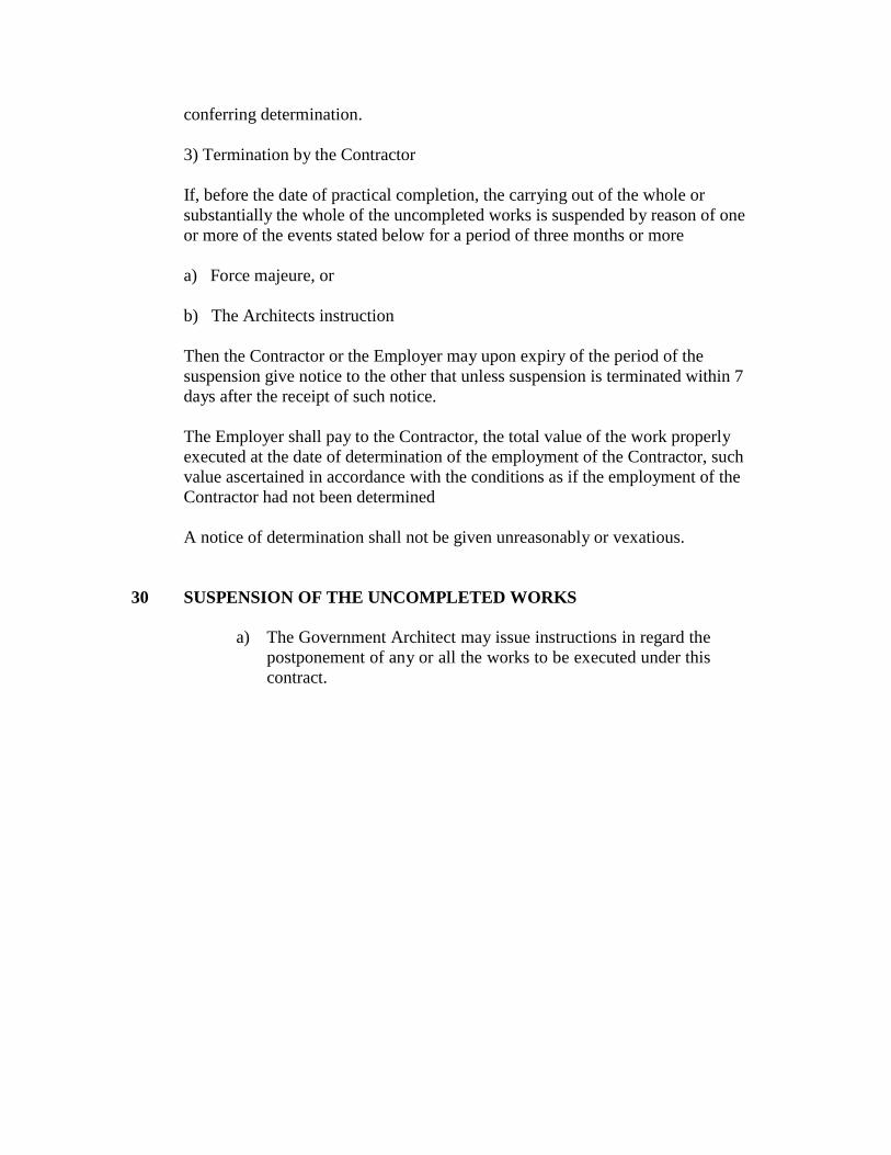
conferring determination.
3) Termination by the Contractor
If, before the date of practical completion, the carrying out of the whole or
substantially the whole of the uncompleted works is suspended by reason of one
or more of the events stated below for a period of three months or more
a) Force majeure, or
b) The Architects instruction
Then the Contractor or the Employer may upon expiry of the period of the
suspension give notice to the other that unless suspension is terminated within 7
days after the receipt of such notice.
The Employer shall pay to the Contractor, the total value of the work properly
executed at the date of determination of the employment of the Contractor, such
value ascertained in accordance with the conditions as if the employment of the
Contractor had not been determined
A notice of determination shall not be given unreasonably or vexatious.
30 SUSPENSION OF THE UNCOMPLETED WORKS
a) The Government Architect may issue instructions in regard the
postponement of any or all the works to be executed under this
contract.
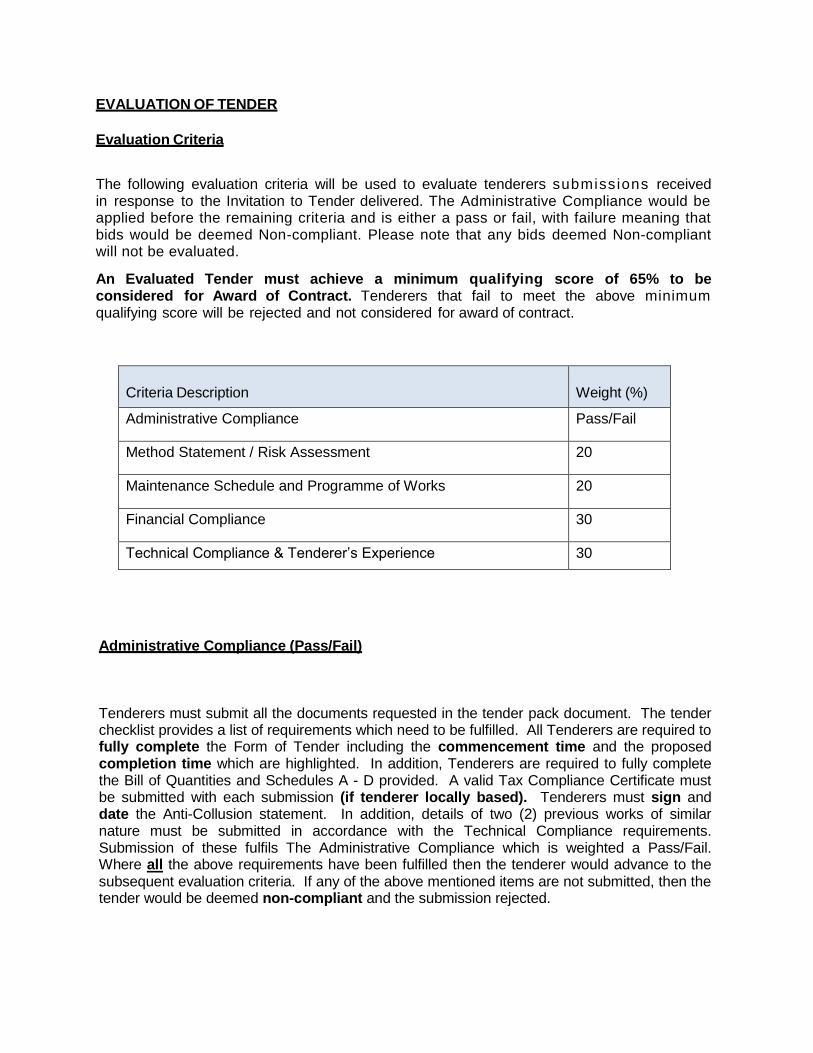
EVALUATION OF TENDER
Evaluation Criteria
The following evaluation criteria will be used to evaluate tenderers submiss ions received in response to the Invitation to Tender delivered. The Administrative Compliance would be applied before the remaining criteria and is either a pass or fail, with failure meaning that bids would be deemed Non-compliant. Please note that any bids deemed Non-compliant will not be evaluated.
An Evaluated Tender must achieve a minimum qualifying score of 65% to be considered for Award of Contract. Tenderers that fail to meet the above minimum qualifying score will be rejected and not considered for award of contract.
Criteria Description
Weight (%)
Administrative Compliance Pass/Fail
Method Statement / Risk Assessment 20
Maintenance Schedule and Programme of Works 20
Financial Compliance 30
Technical Compliance & Tenderer’s Experience 30
Administrative Compliance (Pass/Fail) Tenderers must submit all the documents requested in the tender pack document. The tender checklist provides a list of requirements which need to be fulfilled. All Tenderers are required to fully complete the Form of Tender including the commencement time and the proposed completion time which are highlighted. In addition, Tenderers are required to fully complete the Bill of Quantities and Schedules A - D provided. A valid Tax Compliance Certificate must be submitted with each submission (if tenderer locally based). Tenderers must sign and date the Anti-Collusion statement. In addition, details of two (2) previous works of similar nature must be submitted in accordance with the Technical Compliance requirements. Submission of these fulfils The Administrative Compliance which is weighted a Pass/Fail. Where all the above requirements have been fulfilled then the tenderer would advance to the subsequent evaluation criteria. If any of the above mentioned items are not submitted, then the tender would be deemed non-compliant and the submission rejected.

Method Statement and Risk Assessment (20%)
Tenderers are required to submit a Method Statement to be used to help manage the work and ensure that the necessary precautions have been communicated to all parties so the wellbeing of the workforce is not affected. This will be a means of controlling specific Health and Safety risks identified, (example: damage to sensitive equipment and protection for working on a Hospital Site). Tenderers should provide a fully detailed outline of the work task or process which should be completed in carrying out the said works. Risk control strategies and procedures should also be identified to ensure that all the significant Health and Safety risks can be lessened. Tenderers should also submit a risk method statement to show who is responsible and how to eliminate (or reduce as far as possible) the possibility of an accident occurring where individuals may suffer injury or work related illness, or where property may be damaged. Ensuring Health and Safety of all throughout the works is paramount to the project’s success. This criterion would be assessed by a 20% weighting. Maintenance Schedule and Programme of Works (20%) Tenderers are required to provide Maintenance Manuals including; Operation Instructions, Equipment Catalogues and As-installed Drawings. The information should not be limited to and must include; cleaning, lubrication, balancing, testing, commissioning and adjustment of the equipment and accessories in accordance with the Manufacturer’s recommendations, the design drawings and technical specifications. Tenderers submissions must also show consistency of maintenance; including repair and or replacement of any part or parts of the installation which malfunction or prove to be defective whether under Manufacturer’s guarantee or not. Please note when required repairs are to be made with a minimum of downtime for the equipment. Tenderers are required to submit a complete Programme of works with a list of all activities which would be carried out to; supply, deliver, install, test, commission and maintain the entire works. The programme should effectively show start and end dates, delivery dates of key equipment, duration of key activities, the total duration for completing the works, testing, commissioning and hand over dates. Maintenance schedules and Programmes with the necessary requirements would be assessed by obtaining a required percentage out of 20%.

Financial Compliance (30%)
The tendered price is a significant component and the Government of Montserrat will seek to ensure that the works are undertaken at the Most Economically Advantageous Tendered Price. None the less , t he Government of Montserrat is not bound to accept the lowest or any tender. However, there are other factors as listed in the criterion description for evaluation and these will be considered proportionately.
The percentage for this criterion will be calculated proportionately in comparison to other priced submissions from tenderers, and assessed by obtaining a required percentage weighting out of (30%).
The Hon F.S. has advised that Contractors are to reduce their dependency on GOM taking the Risk of providing substantial Advanced Payments to them. In addition, consideration with strong supporting evidence will be required for all Advanced payment request Contractors put in their Payment Schedules of more than 20%.
Technical Compliance and Experience (30%)
Adherence to the technical specification is paramount to tenderers achieving success in the evaluation process. Prospective tenderers need to provide details of at least 2 previous contracts completed within the past 10 years of a similar nature to the scope of works of this tender with a value of a minimum $400,000.00 for material and labour and a minimum value of $180,000 for labour only. These details should include but are not limited to the following; the entity or person for which the work was completed, contact information for the entity or person, the value of the works, the location of the works and photographic evidence of different stages of the works. In addition, the prospective tenders can submit award letters for works in lieu of the above mentioned information. The percentage for this criterion will be calculated proportionately in comparison to other submissions from tenderers and assessed on a weighting of (30%).
Start Date or
Date of Award
Description of Works Name of Client Price of Contract
Date Completed

GOVERNMENT OF MONTSERRAT
TENDER SUBMISSION ANTI-COLLUSION CERTIFICATE
I/WE CERTIFY THAT THIS TENDER IS MADE IN GOOD FAITH, AND THAT WE HAVE NOT FIXED OR ADJUSTED THE
AMOUNT OF THE TENDER BY OR UNDER OR IN ACCORDANCE WITH ANY AGREEMENT OR ARRANGEMENT WITH ANY
OTHER PERSON. I/WE ALSO CERTIFY THAT WE HAVE NOT AND I/WE UNDERTAKE THAT WE WILL NOT BEFORE THE
AWARD OF ANY CONTRACT FOR THE WORK:
DISCLOSE THE TENDER PRICE OR ANY OTHER FIGURES OR OTHER INFORMATION IN CONNECTION WITH THE TENDER
TO ANY OTHER PARTY (INCLUDING ANY OTHER COMPANY OR PART OF A COMPANY FORMING PART OF A GROUP OF
COMPANIES OF WHICH I AM/WE ARE A PART OF) NOR TO ANY SUB-CONTRACTOR (WHETHER NOMINATED OR
DOMESTIC) NOR SUPPLIER (WHETHER NOMINATED OR DOMESTIC) OR ANY OTHER PERSON TO WHOM SUCH
DISCLOSURE COULD HAVE THE EFFECT OF PREVENTING OR RESTRICTING FULL COMPETITION IN THIS TENDERING
EXERCISE
ENTER INTO ANY AGREEMENT OR ARRANGEMENT WITH ANY PERSON THAT THEY SHALL REFRAIN FROM TENDERING,
THAT THEY SHALL WITHDRAW ANY TENDER ONCE OFFERED OR VARY THE AMOUNT OF ANY TENDER TO BE
SUBMITTED OR OTHERWISE COLLUDE WITH ANY PERSON WITH THE INTENT OF PREVENTING OR RESTRICTING FULL
COMPETITION
PAY, GIVE OR OFFER PAY OR GIVE ANY SUM OF MONEY OR OTHER VALUABLE CONSIDERATION DIRECTLY OR
INDIRECTLY TO ANY PERSON FOR DOING OR HAVING DONE OR CAUSING OR HAVING CAUSED TO BE DONE IN
RELATION TO ANOTHER TENDER OR PROPOSED TENDER FOR THE WORK ANY ACT OR THING OF THE SORT
DESCRIBED AT I), II) OR III) ABOVE.
I/WE FURTHER DECLARE THAT I/WE HAVE NO KNOWLEDGE EITHER OF ANY SUM QUOTED OR OF ANY OTHER
PARTICULARS OF ANY OTHER TENDER FOR THIS CONTRACT BY ANY OTHER PARTY.
I/WE FURTHER CERTIFY THAT THE PRINCIPLES DESCRIBED ABOVE HAVE BEEN, OR WILL BE, BROUGHT TO THE
ATTENTION OF ALL SUB-CONTRACTORS, SUPPLIERS AND ASSOCIATED COMPANIES PROVIDING SERVICES OR
MATERIALS CONNECTED WITH THE TENDER AND ANY CONTRACT ENTERED INTO WITH SUCH SUB-CONTRACTORS, SUPPLIERS OR ASSOCIATED COMPANIES WILL BE MADE ON THE BASIS OF COMPLIANCE WITH THE ABOVE
PRINCIPLES BY ALL PARTIES.
I/WE ACKNOWLEDGE THAT ANY BREACH OF THE FOREGOING PROVISIONS SHALL LEAD AUTOMATICALLY TO THIS
TENDER BEING DISQUALIFIED AND MAY LEAD TO CRIMINAL OR CIVIL PROCEEDINGS.THE GOVERNMENT OF
MONTSERRAT SHALL TREAT ANY TENDER RECEIVED IN CONFIDENCE BUT RESERVES THE RIGHT TO MAKE THE SAME
AVAILABLE TO ANY OTHER FUNDING ORGANISATION OR STATUTORY REGULATORY AUTHORITY EITHER HAVING
JURISDICTION OVER THE WORKS OR WHO MAY NOW OR AT ANY TIME IN THE FUTURE HAVE STATUTORY POWER TO
REQUIRE DISCLOSURE OF THIS TENDER.
IN THIS CERTIFICATE, THE WORD ‘PERSON’ INCLUDES ANY PERSONS AND ANY BODY OR ASSOCIATION, INCORPORATED OR UNINCORPORATED; ANY AGREEMENT OR ARRANGEMENT INCLUDES ANY TRANSACTIONS, FORMAL OR INFORMAL AND WHETHER LEGALLY BINDING OR NOT; AND ‘THE WORK’ MEANS THE WORK IN RELATION
TO WHICH THIS TENDER IS MADE.
SIGNATURE………………………………………………. IN CAPACITY OF ……….……….…….…….…………..
DATE……………………………………………………2017
DULY AUTHORISED TO SIGN TENDERS AND ACKNOWLEDGE THE CONTENTS OF THE ANTI-COLLUSION CERTIFICATE
FOR AND ON BEHALF OF:
NAME OF FIRM……………………..…………………………………………………………………………
FULL POSTAL ADDRESS…………………………………………………………………………….
TELEPHONE NO………………………….……. FAX NO ………………………………………….
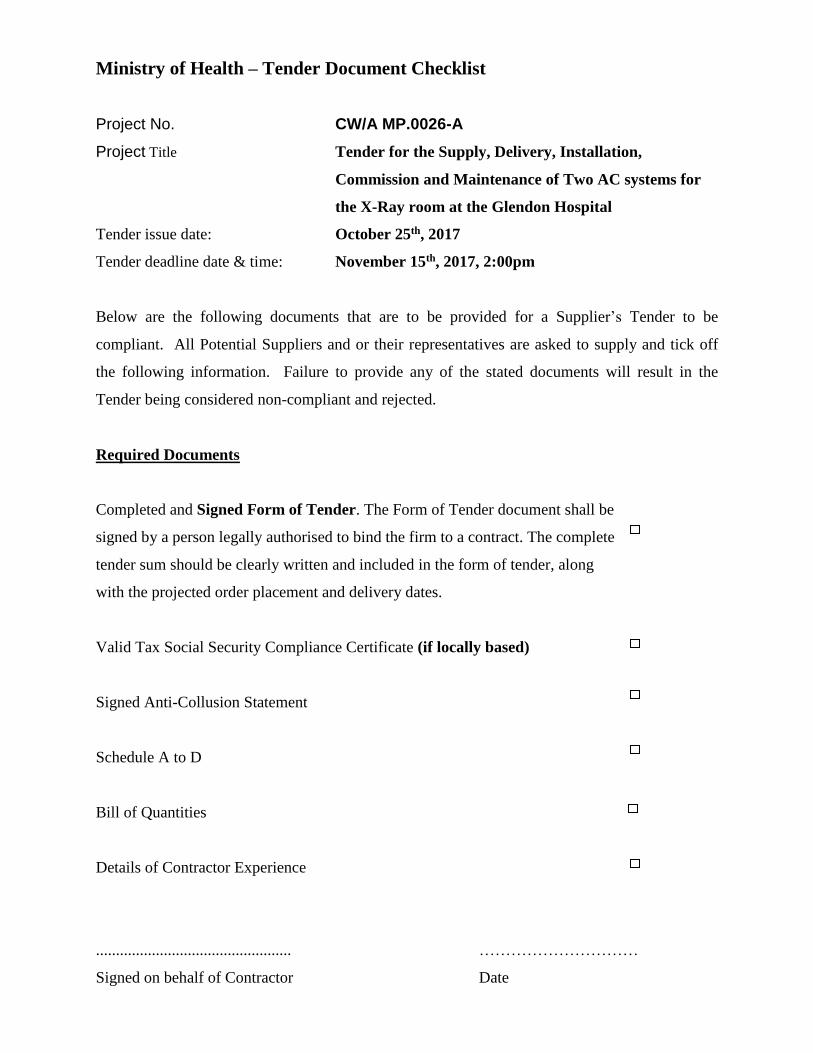
Ministry of Health – Tender Document Checklist
Project No. CW/A MP.0026-A
Project Title Tender for the Supply, Delivery, Installation,
Commission and Maintenance of Two AC systems for
the X-Ray room at the Glendon Hospital
Tender issue date: October 25th, 2017
Tender deadline date & time: November 15th, 2017, 2:00pm
Below are the following documents that are to be provided for a Supplier’s Tender to be
compliant. All Potential Suppliers and or their representatives are asked to supply and tick off
the following information. Failure to provide any of the stated documents will result in the
Tender being considered non-compliant and rejected.
Required Documents
Completed and Signed Form of Tender. The Form of Tender document shall be
signed by a person legally authorised to bind the firm to a contract. The complete
tender sum should be clearly written and included in the form of tender, along
with the projected order placement and delivery dates.
Valid Tax Social Security Compliance Certificate (if locally based)
Signed Anti-Collusion Statement
Schedule A to D
Bill of Quantities
Details of Contractor Experience
................................................. …………………………
Signed on behalf of Contractor Date
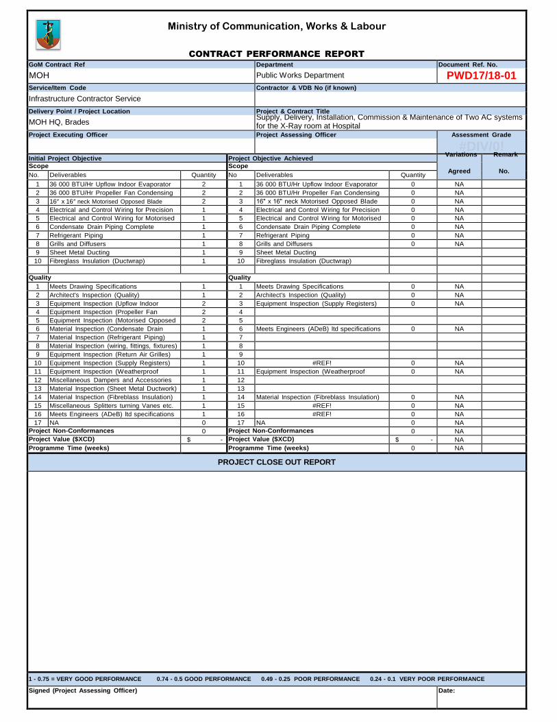
Ministry of Communication, Works & Labour
CONTRACT PERFORMANCE REPORT
GoM Contract Ref Department Document Ref. No.
MOH Public Works Department PWD17/18-01 Service/Item Code Contractor & VDB No (if known)
Infrastructure Contractor Service
Delivery Point / Project Location Project & Contract Title
MOH HQ, Brades Supply, Delivery, Installation, Commission & Maintenance of Two AC systems for the X-Ray room at Hospital
Project Executing Officer Project Assessing Officer Assessment Grade
#DIV/0! Initial Project Objective Project Objective Achieved Scope Scope
Agreed
No. No. Deliverables Quantity No Deliverables Quantity
1 36 000 BTU/Hr Upflow Indoor Evaporator 2 1 36 000 BTU/Hr Upflow Indoor Evaporator 0 NA 2 36 000 BTU/Hr Propeller Fan Condensing 2 2 36 000 BTU/Hr Propeller Fan Condensing 0 NA 3 16ʺ x 16ʺ neck Motorised Opposed Blade 2 3 16ʺ x 16ʺ neck Motorised Opposed Blade 0 NA 4 Electrical and Control Wiring for Precision 1 4 Electrical and Control Wiring for Precision 0 NA 5 Electrical and Control Wiring for Motorised 1 5 Electrical and Control Wiring for Motorised 0 NA 6 Condensate Drain Piping Complete 1 6 Condensate Drain Piping Complete 0 NA 7 Refrigerant Piping 1 7 Refrigerant Piping 0 NA 8 Grills and Diffusers 1 8 Grills and Diffusers 0 NA 9 Sheet Metal Ducting 1 9 Sheet Metal Ducting 10 Fibreglass Insulation (Ductwrap) 1 10 Fibreglass Insulation (Ductwrap)
Quality Quality
1 Meets Drawing Specifications 1 1 Meets Drawing Specifications 0 NA 2 Architect's Inspection (Quality) 1 2 Architect's Inspection (Quality) 0 NA 3 Equipment Inspection (Upflow Indoor 2 3 Equipment Inspection (Supply Registers) 0 NA 4 Equipment Inspection (Propeller Fan 2 4 5 Equipment Inspection (Motorised Opposed 2 5 6 Material Inspection (Condensate Drain 1 6 Meets Engineers (ADeB) ltd specifications 0 NA 7 Material Inspection (Refrigerant Piping) 1 7 8 Material Inspection (wiring, fittings, fixtures) 1 8 9 Equipment Inspection (Return Air Grilles) 1 9 10 Equipment Inspection (Supply Registers) 1 10 #REF! 0 NA 11 Equipment Inspection (Weatherproof 1 11 Equipment Inspection (Weatherproof 0 NA 12 Miscellaneous Dampers and Accessories 1 12 13 Material Inspection (Sheet Metal Ductwork) 1 13 14 Material Inspection (Fibreblass Insulation) 1 14 Material Inspection (Fibreblass Insulation) 0 NA 15 Miscellaneous Splitters turning Vanes etc. 1 15 #REF! 0 NA 16 Meets Engineers (ADeB) ltd specifications 1 16 #REF! 0 NA 17 NA 0 17 NA 0 NA
Project Non-Conformances 0 Project Non-Conformances 0 NA Project Value ($XCD) $ - Project Value ($XCD) $ - NA Programme Time (weeks) Programme Time (weeks) 0 NA
PROJECT CLOSE OUT REPORT
1 - 0.75 = VERY GOOD PERFORMANCE 0.74 - 0.5 GOOD PERFORMANCE 0.49 - 0.25 POOR PERFORMANCE 0.24 - 0.1 VERY POOR PERFORMANCE
Signed (Project Assessing Officer) Date:
Variations Remark
