x. energy conversion research academic … · prof. c. c. oates graduate students e. k. levy r....
TRANSCRIPT

X. ENERGY CONVERSION RESEARCH
Academic and Research Staff
Prof. G. A. Brown Prof. J. L. Kerrebrock Prof. J. E. McCuneProf. E. S. Pierson Prof. M. A. Hoffman
Prof. C. C. Oates
Graduate Students
E. K. Levy R. Decher W. H. Evers, Jr.R. J. Thome G. W. Zeiders, Jr.
A. A LARGE NONEQUILIBRIUM MHD GENERATOR
1. Introduction
It has been clear for some time that nonequilibrium ionization caused by electron
heating can be produced in magnetogasdynamic generators, provided the Joule dissi-
pation in the gas can be raised to the level required to elevate the electron temper-
ature. 2 Idealized generator calculations predict that it should be quite easy to realize
such levels of dissipation. In practice, however, generators operating with the seeded
noble gases, which seem optimum for production of electron heating, have, for the most
part, failed to yield the expected nonequilibrium ionization. The outstanding exception
to this statement is the disc-type Hall generator described by Klepeis and Rosa.3 The
data supporting these conclusions has been summarized by Kerrebrock. 4
It has been proposed by one of the present authors that the lack of success of the
segmented-electrode generators can be attributed to a shorting of the Hall field by a
highly conducting layer of gas near the electrode wall.5 It was proposed that the high
conductivity initially results from the concentrated dissipation resulting from the elec-
trode segmentation and is supported by the dissipation caused by the shorted Hall cur-
rent. The theory appears to explain the behavior of a least two generators, one of which
operated at a low Hall parameter, for which the shorting effect was predicted to be
small, and the other at a high Hall parameter, for which the effect should be very large.
The success of the disc-type Hall generator is further evidence in support of the
theory, since the losses attributable to electrode segmentation are eliminated in
this design.
It might then seem that the disc geometry is optimum for nonequilibrium generators.
But, since this is a Hall generator, this type suffers from the disadvantage that it must
operate at very large Hall parameters in order to yield the levels of efficiency desired
for nuclear-MHD power plants. At these large Hall parameters, other losses, such as
This work was supported by the U. S. Air Force (Research and Technology Division)under Contract AF33(615)-3489 with the Air Force Aero Propulsion Laboratory, Wright-Patterson Air Force Base, Ohio.
QPR No. 83

(X. ENERGY CONVERSION RESEARCH)
those that are due to electrothermal waves6, 7 and steady nonuniformities,8 may seri-ously degrade the efficiency.
For these reasons, a systematic attempt has been made to design a segmented-
electrode generator which will not exhibit the electrode shorting phenomenon and still
be capable of elevation of the electron temperature above the gas stagnation temperature.
The design has been based on the results of the theory given elsewhere. 5 It will bedescribed in detail below.
We were fortunate in having available for the study a graphite inert-gas heater
capable of a flow of 0. 4 kg s - l of helium at 20000K stagnation temperature and 5 atm
stagnation pressure. This makes possible a supersonic flow in which viscous effects
are small.
As we shall see, the results of the experiments conducted thus far do not prove the
engineering feasibility of segmented electrode nonequilibrium generators. They do serve,
however, to indicate some of the critical problems remaining to be solved.
2. Description of the Facility
The hot plasma for use in the experiments is supplied by a large heat-sink facility
illustrated in Fig. X-1. This facility is similar in concept to the conventional pebble-
bed heaters, but here the core is constructed of 7 separate cylindrical blocks of graphite,22 inches in diameter, each of which is drilled with approximately 1100 1/4 inch holes.
The core is heated electrically by graphite glow bars at an input power of approximately
250 kilowatts. Thermal insulation is provided by graphite felt and graphite fibres. Elec-
trical insulation is provided by boron-nitride spacers.
The test gas is supplied from a manifold of up to 20 gas bottles, and is deliveredthrough two stages of regulators in series, to the inlet at the bottom of the heater. Theseed material is injected by a motor-driven stainless-steel syringe into a "bed" ofoxygen-free copper bars which have been heated to 11000K. A subsidiary flow of theflow of the test gas is also passed through the copper bars, and the mixture of vapor-
ized seed material and gas is injected into the plenum chamber at the outlet from the
graphite core, where it mixes with the mainstream. The seed is carried from the cop-
per bed to the plenum by a molybdenum tube sheathed with graphite.
No serious problems have been encountered in repeated operation of this facility at
2000 0 K. This temperature is the approximate limit set by the balance of the available
input power against the heat losses.
3. Description of the Channel
a. Over-all Channel Geometry
The MHD channel over-all dimensions were selected to take maximum advantage of
the magnet that was used. The magnet has pole face dimensions of 6 x 18 inches and
QPR No. 83

-4Ca
cnM~c
,-4
00ooPL(Y

(X. ENERGY CONVERSION RESEARCH)
produces approximately 1. 3 Tesla at a gap of 2 1/4 inches. As a result, an MHD chan-nel with a length of 18 inches and an exit height of 6 inches was selected (see Figs. X-2,
X-3, X-4, X-5).
The channel was designed for the following nominal flow conditions: inlet Mach num-
ber of 2. 0 with inlet stagnation temperature of 2000 K, inlet stagnation pressure of 5 atm
and mass flow of helium of 0. 40 kg/sec. This led to the over-all dimensions shown in
Fig. X-2.
A water-cooled copper nozzle of rectangular cross section and constant width was
designed and built to provide the desired inlet Mach number to the channel with a smooth
transition. This nozzle was effectively at ground potential.
A rectangular, constant-area supersonic diffuser was designed to provide good pres-
sure recovery. Great care was exercised in the design to insure electrical isolation of
the MHD channel and plasma from ground. The diffuser walls consist of small copper
bricks or blocks 1 1/2 X 1/2 inches deep mounted on an epoxy plastic support wall. The
blocks have sufficient volume to remain at low temperature throughout the run, since
the run duration is short. Also, each block is electrically and thermally insulated from
adjacent blocks and from the support wall by mica strips, 1/16 inch thick.
A copper subsonic diffuser was attached to the exit of the supersonic diffuser. The
plasma exhausted into a large plenum chamber vented to atmospheric pressure. This
plenum was electrically insulated from ground.
b. Electrode-Wall Design
The electrode geometry and materials were selected on the basis of the theory pre-
viously developed 5 for the behavior of segmented electrodes in a generator where non-
equilibrium ionization of the gas is possible. In order to suppress the electrode-wall
shorting predicted by this theory, it is desirable to use rather coarse segmentation
ratios (i. e. , the ratio of the channel height to electrode pitch) of the order of 5 to 10.
The theory also indicates that it is advantageous to keep the electrode wall cold in order
to suppress the nonequilibrium ionization in the gas layer near that wall.
An electrode pitch of 3/4 inch was selected. This yields a segmentation ratio of 4.7
at the inlet increasing to 8. 0 at the channel exit.
As shown in Fig. X-2, the electrode itself is made of pyrolytic graphite, 5/16 inch
long and 1 1/2 inches wide. The laminae of the pyrolytic graphite lie parallel to the
electrode-wall surface in order to promote heating of the emitting surface of the elec-trode and reduce heat transfer into the electrode. Each electrode is mounted in a U-
shaped copper yoke to which the external electrical connection is made.
Since the run durations were from 10 to 30 seconds, the heat-sink principle wasemployed in designing insulator segments that would remain cold throughout the run.These consisted of copper blocks of sufficient volume to remain at low temperatures
QPR No. 83

NOZZLE -
5"
MHD CHANNEL
(VIEW WITH TOP INSULAT
8 10 12 12 -
I- . .
..I
I I IT
DIFFI 1SF
)R WALL REMOVED)
4 16 18 20 22
18"1''
15 5"2
FIBERGLASEPOXY PLASTICSUPPORT WALL
PYROLYTICGRAPH ITE
ELECTRODE
- ELECTRODEWALL
DETAIL
COPPER YOKEELECTRODE
HOLDER
EXTERNALELECTRODE
CONNECTION
Fig. X-Z. MHD channel layout.
STATION HEIGHT WIDTH
3" 1 "A 2- 1
B' 1"B 31 112 2
1''C 6" 1
1 "D 6" 1
E 6"E 6 " 2-
I
SUPERSONIC SECTION
-.- R
I I

Fig. X-3.
Side view of electrode wall showingfirst nine segmented electrodes.
Fig. X-4.
Assembly of Armco iron blocks forinsulator wall on steel bolts cov-ered with mica tubes.
Fig. X-5.
MHD channel partly assembledshowing top electrode wall mountedon insulator wall.
QPR No. 83

(X. ENERGY CONVERSION RESEARCH)
(--Z00C) for the expected test durations. These copper blocks were electrically and
thermally insulated from the adjacent electrodes and the support wall by mica strips,
1/16 inch thick.
Twenty-three electrodes and insulator segments were assembled on each Fiberglas
epoxy plastic-support wall.
c. Insulator-Wall Design
The first insulator wall consisted of sheets of boron nitride, 1/4 inch thick, epoxied
to a plastic-support wall. As will be discussed below, insulator wall and/or insulator
boundary layer shorting revealed by the results of runs 1 and 2 led to redesign
of this wall.
The second insulator wall was assembled from small blocks of Armco magnet iron,
each of which was electrically and thermally insulated by thick mica strips, 1/16 inch
thick, similarly to the diffuser-wall design. The iron blocks had sufficient depth to
remain at relatively low temperature during the run. The use of iron reduced the effec-
tive magnet gap to a minimum and increased the magnetic field to 1. 4 Tesla.
Each set of blocks lying in the transverse direction was assembled on a long bolt
covered with a mica tube for electrical insulation. Holes were drilled along the axis of
each bolt and a small pressure tap was inserted into each bolt between two iron blocks.
These flush-wall static pressure taps on the insulator wall provided a detailed profile
of the static pressure in the flow direction.
The sets of iron blocks were assembled on epoxy plastic-support walls which also
provided a pressure-tight seal for the entire insulator wall.
d. Exciter
In order to examine the effect of higher electron density on the starting character-
istics of the generator, an external exciter was designed and installed at the entrance
of the channel. Several different configurations were used in the various runs. In all
cases, a battery bank was used to apply a DC voltage across the channel near the
entrance. This battery bank was so connected that it could be inserted or removed when
desired during the run at each test condition. In all runs, data were taken at a series
of load resistances both with the exciter batteries connected and removed.
In run 2, a 360-volt battery bank was connected across electrode pairs 1, 2, and 3.
There was provision for inserting this exciter voltage in series with the load resistor
when desired.
In runs 3 to 6, the battery bank was connected only to electrode pair 3. Electrodes
1 and 2 were left open throughout the run. The voltage applied in runs 3, 5, and 6 was
260 volts. In run 4, this voltage was reduced to ~75 volts. In run 6, a 3-ohm resistor
was permanently connected across electrode pair 3 throughout the run. As in all other
QPR No. 83

(X. ENERGY CONVERSION RESEARCH)
runs, the exciter batteries could be inserted in series with the load resistorwhen desired.
The exciter was removed from the electrodes altogether in runs 7 and 8 and con-nected to the row of insulator wall blocks near electrode pair 2. In run 7, a set of four12-volt batteries was connected across each of the 7 pairs of insulator wall blocksthrough a 4-ohm external resistor. These batteries could be applied across the chan-nel so that the current would flow in the direction of the magnetic field. In run 8, abattery bank totaling 260 volts was connected across all 7 pairs of iron blocks with theblocks in parallel.
4. Experimental Results
Eight experimental runs have been conducted thus far, two with the boron-nitrideside walls, and six with the iron-peg walls. Of these, the most useful were runs 2, 5,6, and 7. The principal parameters for these are listed in Table X-1. Helium seededwith cesium was used as working gas in all of the listed runs.
Table X-1. Parameters for experimental runs.
Cs Mole HallRun No. Side Wall P Fraction Parameter T M p B
(atm) (0 K) (atm) (Tesla)
2 BN 4. 5 .002 3. 8 2000 2. 1 .50 1. 3
5 Iron 4.1 z0 4.5-6. 3 2000 2. 1-2.5 .45-.27 1.4
6 Iron 3. 1 .003 6.0-8. 3 2000 2. 1-2. 5 .34-.21 1.4
7 Iron 4.5 .002 4.1-5.7 2000 2. 1-2.5 .50-.30 1.4
It should be noted at the outset that in none of the runs did the generator produce asignificant fraction of the expected power. The data have not been completely analyzedso it will be possible to report only the experimental results, and offer some possiblereasons for the poor performance of the generator.
From the pressure distributions (see Fig. X-6), we conclude that the channel
operated supersonically, and essentially at the design Mach numbers of 2 at the inlet and2. 5 at the outlet in all runs in which the stagnation pressure was above ~3 atm absolute.As will be noted below, there is a possibility that the magnetogasdynamic effects led toseparation on the cathode wall.
The iron-peg-wall channel was operated with a mixture of 70 per cent Argon, 30 percent Helium, as a Faraday generator in run 3 and as a Hall generator in run 4. In both
QPR No. 83

(X. ENERGY CONVERSION RESEARCH)
10 15
Electrode Pair
Fig. X-6. Typical static pressure and Mach number variations along the channel.
cases, the open-circuit coltages were very low, and the output negligible. Although the
reasons for this are not fully understood, it is probable that the higher Hall parameter
and lower electrode temperatures were major contributing factors.
a. Boron-Nitride Side-Wall Runs
The channel with boron-nitride side walls was operated at the test conditions given
for run 2 in Table X-1. For these conditions, as for the remaining runs, the conduc-
tivity of the plasma should have been approximately 5 mho m-1 if the electron mole frac-
tion were frozen at the stagnation value.
An attempt was made to start the generator by applying a potential to electrode pairs
1, 2, and 3 so as to increase the current in these electrode pairs. With the exciter
operating, the currents indicated in Fig. X-7 were produced. It will be noted that the
current per electrode pair increased down the channel, more rapidly with the 3-ohm
load resistance than with the 10-ohm and 25-ohm resistors. From this it may be inferred
that the conductivity was increasing down the channel.
The voltage-current characteristics for electrode pairs 5 and 23 are compared (see
Fig. X-8) to the characteristic that would be expected for ionization frozen at the
stagnation value, and with electrode losses characteristic of the "normal mode." 5 This
QPR No. 83
I I I I
Run5
Mach Number
o
Lressure Ratio
I I I I
3
E2 z
oU0
.05 I
OLC
o252:)

" 15E
o
U 0
5
O'0
Fig. X-7. Current per electrode pair along thevarious load resistances.
Theoretical, for ConstantSlonization Frozen at
Stagnation Condition
Pair 23/Pair 5
No. 2
Pair 2Poir 5
\ \
Run
channel for
4 8 12 16 2
Current per Electrode, Amp.
Fig. X-8. Voltage-current characteristics forative electrode pairs.
two represent-
QPR No. 83
10 15
Electrode Number
I I I IRuvn 2
Solid Points From Voltages * * 3 n
Open Points From Ammeters
- 0
0* S
o 0
- A- 10 1 -
25f.
I I I I
800
600
400
200
0

(X. ENERGY CONVERSION RESEARCH)
performance is nearly equal to that predicted by the electrode theory of Hurwitz, Kilb,
and Sutton, 9 and seems to be a reasonable upper limit to what can be expected if no elec-
tron heating occurs.
We see that the open-circuit voltage was very much less than the expected value;
however, the current in electrode pair 23 did exceed the frozen ionization value by a sub-
stantial factor.
When the exciter was turned off, the currents were negligible.
From the low open-circuit voltage, it was concluded that the generator was probably
internally shorted through the boundary layer on the insulating wall. Because of its low
thermal conductivity, the boron-nitride side wall ran quite hot, and it was felt that this
probably aggravated the shorting.
Accordingly, the iron side walls described above were constructed.
b. Iron Side-Wall Runs
In run 5, the generator was operated with very low seed fraction (because the seeder
jammed), both with and without excitation on electrode pair 3. The exciter made very
little difference in this run, so the data will be given for points without excitation.
More detailed instrumentation was available for this channel than for the previous
one, so that it has been possible to prepare the approximate potential diagrams shown
10 fl Resistances Anode Wall
0
+
a0 o o
+ + + ++I913 17 2
Cathode Wall 21 23
Fig. X-9. Approximate potential diagram for 10-ohm load resistances for run 5.
in Figs. X-8, X-9, and X-10. The crosses indicate points where the voltage was
measured at the electrodes, while the circles indicate probes on the insulating wall.
A representative potential diagram from run 5 for the 10-ohm load case is shown in
Fig. X-9. The potential pattern is almost symmetric but does show some evidence
of a potential "valley" along the cathode wall. This region of low potential tended to
QPR No. 83

Open Circuit
Fig. X-10. Approximate potential diagrams for open-circuit condition for run 6.
Short Circuit
21 23
Fig. X- 11. Approximate potential diagrams for open-circuit and short-circuitconditions for run 7.
QPR No. 83
Anode Wall
(X. ENERGY CONVERSION RESEARCH)
grow at larger load resistances. At lower load resistances it tended to diminish, and
essentially disappeared at short circuit.
In run 6, the same channel was operated at a relatively low stagnation pressure, and
high seed fraction. The Hall parameter varied between 6. O0 at the channel entrance and
8. 3 at the exit. A 3-ohm load was maintained on electrode pair 3 for all points. With
these conditions, an open-circuit voltage of 365 volts was produced at electrode pair 15.
The approximate potential diagram for the open-circuit is shown in condition
Fig. X-10. When a load was applied, the channel behaved much as in run 5.
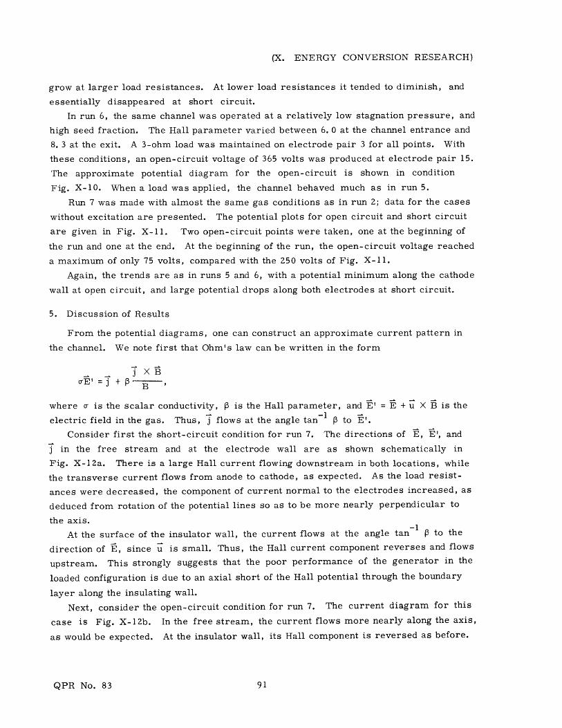
Run 7 was made with almost the same gas conditions as in run 2; data for the cases
without excitation are presented. The potential plots for open circuit and short circuit
are given in Fig. X-ll1. Two open-circuit points were taken, one at the beginning of
the run and one at the end. At the beginning of the run, the open-circuit voltage reached
a maximum of only 75 volts, compared with the 250 volts of Fig. X-11.
Again, the trends are as in runs 5 and 6, with a potential minimum along the cathode
wall at open circuit, and large potential drops along both electrodes at short circuit.
5. Discussion of Results
From the potential diagrams, one can construct an approximate current pattern in
the channel. We note first that Ohm's law can be written in the form
j XBcrE' =j +- B '
where cr is the scalar conductivity, P is the Hall parameter, and E' = E + u X B is the
electric field in the gas. Thus, j flows at the angle tan- 1 p to E'.
Consider first the short-circuit condition for run 7. The directions of E, E', and
j in the free stream and at the electrode wall are as shown schematically in
Fig. X-12a. There is a large Hall current flowing downstream in both locations, while
the transverse current flows from anode to cathode, as expected. As the load resist-
ances were decreased, the component of current normal to the electrodes increased, as
deduced from rotation of the potential lines so as to be more nearly perpendicular to
the axis. -1At the surface of the insulator wall, the current flows at the angle tan I to the
direction of t, since u is small. Thus, the Hall current component reverses and flows
upstream. This strongly suggests that the poor performance of the generator in the
loaded configuration is due to an axial short of the Hall potential through the boundary
layer along the insulating wall.
Next, consider the open-circuit condition for run 7. The current diagram for this
case is Fig. X-12b. In the free stream, the current flows more nearly along the axis,
as would be expected. At the insulator wall, its Hall component is reversed as before.
QPR No. 83

(X. ENERGY CONVERSION RESEARCH)
ANODE WALL
NEAR SHORT CIRCUIT
(a)
NEAR OPEN CIRCUIT
(b)Fig. X-12. Schematic diagram of electric fields and currents for
short-circuit and open-circuit conditions in run 7.
The transverse component may also reverse if the open-circuit voltage is largeenough. To the accuracy that the current diagrams can be drawn, it is diffi-
cult to determine whether the transverse current is positive or negative at thispoint.
The low-potential region near the cathode has the appearance of a separated region,
as reported by Louis, Gal, and Blackburn.10 Such a separation is consistent with a very
large Hall current in the free stream, since such a current would produce a j X B force
toward the cathode. Such a large Hall current, however, would have to be supported by
a large transverse current. The return path for this transverse current is not clear, at
present. It may be through the insulator boundary layer.
6. Conclusions
On the basis of these preliminary results, we conclude that the behavior of the insu-
lator boundary layer is a crucial factor in determining the performance of supersonic
inert-gas generators. There seems to be no evidence in the present results that the
electrode shorting phenomenon previously described 5 limited the performance of these
generators.
J. L. Kerrebrock, M. A. Hoffman, G. C. Oates, R. Decher
QPR No. 83

(X. ENERGY CONVERSION RESEARCH)
References
1. J. L. Kerrebrock, "Conduction in Gases with Elevated Electron Temperatures,"Engineering Aspects of Magnetohydrodynamics (Columbia University Press,New York, 1962), pp. 327-346.
2. J. L. Kerrebrock and M. A. Hoffman, "Nonequilibrium Ionization Due to Electron
Heating: II. Experiments," AIAA J. 2, 1080-1087 (1964).
3. J. Klepeis and R. J. Rosa, "Experimental Studies of Strong Hall Effects and V X BInduced Ionization," Fifth Symposium on Engineering Aspects of Magnetohydrodynam-ics, Massachusetts Institute of Technology, Cambridge, Massachusetts, April 1964.
4. J. L. Kerrebrock, "Magnetohydrodynamic Generators with Nonequilibrium Ioniza-
tion," AIAA J. 3, 591-601 (1965).
5. J. L. Kerrebrock, "Segmented Electrode Losses in MHD Generators with Nonequi-librium Ionization-II," Avco-Everett Research Report 201, January 1965.
6. J. L. Kerrebrock, "Nonequilibrium Ionization Due to Electron Heating: I. Theory,"AIAA J. Z, 1072-1080 (1964).
7. R. Dethlefsen and J. L. Kerrebrock, "Experimental Investigation of Fluctuationsin a Nonequilibrium MHD Plasma," Seventh Symposium on Engineering Aspects ofMagnetohydrodynamics, Princeton University, Princeton, New Jersey, 1966,pp. 117-125.
8. R. J. Rosa, "Hall and Ion-Slip Effects in a Nonuniform Gas," Phys.Fluids 5, 1081-1090 (1962).
9. H. Hurwitz Jr., R. W. Kilb, and G. W. Sutton, "Influence of Tensor Conductivityon Current Distribution in an MHD Generator," J. Appl. Phys. 32, 205 (1961).
10. J. F. Louis, G. Gal, and P. R. Blackburn, "Detailed Theoretical and ExperimentalStudy on a Large MHD Generator," AIAA J. 3, 1482-1490 (1965).
QPR No. 83
