avaya
TRANSCRIPT

585-229-772Issue 1
December 2001
DEFINITY® Proxy AgentRelease 4.0
Installation and Administration

DEFINITY Proxy Agent Release 4.0 Installation and Administration
December 2001 Page 2Contents
Contents 2
Resources and Notices 10
Introduction 10Avaya Resources 11
Sales and Design Support Center (SDSC) 12Technical Services Center (TSC) 13
References 14Avaya References 15Vendor References 18
System Security Notices 20Toll Fraud Security 21
Overview 22
Introduction 22Product Description 23
Alarm-to-Trap Conversion 26DEFINITY_ARS Script 28AUDIX_ARS Script 30CMS_ARS Script 32CONVERSANT_ARS Script 33

DEFINITY Proxy Agent Release 4.0 Installation and Administration
Contents December 2001Page 3
Alarm Forwarding 35SNMP Access 37Enhanced Cut-Through 39DEFINITY Network Management 40
New Features 42Connectivity Scenarios 43System Security 45PA001 Request Form 47Supported Systems 48System Requirements 49
Software Requirements 50DEFINITY Network Management CD-ROMs 51
Customer Pre-Installation Tasks 52
Introduction 52Plan the Connectivity 53
Data Communication Hardware 57Cables for Communication Devices 60
Complete the PA001 Form 66Install the UnixWare Operating System 67
UnixWare Installation Tasks 68

DEFINITY Proxy Agent Release 4.0 Installation and Administration
Contents December 2001Page 4
Administer the Communication Devices 70Administer Security Options 72Change the DIP Switch Settings 75
Settings for 7400B/B+ Data Modules 76Settings for PDMs 77Settings for MPDMs 79
Set the Interface for 7400A Modules 80Execute the Platform Acceptance Test 81
Installing or Upgrading DPA 84
Introduction 84Installation Checklists 85
Technical Verification Checklist 87Customer Acceptance Checklist 88
Understanding the Installation Prompts 89RAM Megabytes Prompt 90Function Prompt 91
Serial I/O Subsystem 95Installing DPA 97Upgrading from DPA 3.0 and Later 107

DEFINITY Proxy Agent Release 4.0 Installation and Administration
Contents December 2001Page 5
Upgrading from DPA 2.0.2 and Earlier 117Removing DPA 119
Help Screens and Commands 121
Introduction 121Functions Window 122Commands and Hotkeys 123Format Conventions 127
Access Procedures 131
Introduction 131Log in to the Proxy Agent 132Access the User Documentation 139Review of the Main Menu 141Review of the Proxy Admin Menu 145Start the Proxy Agent 149Display of the Status Screen 150
Review of the Status Screen Fields 152Display the Status Screen 155
Stop the Proxy Agent 156

DEFINITY Proxy Agent Release 4.0 Installation and Administration
Contents December 2001Page 6
Network Managers Administration 157
Introduction 157Review the Network Managers Screen 158Administer the Network Managers 163
Default Location Administration 166
Introduction 166Review of the Default Location Screen 168Administer the Default Location 174
Alarm Device Administration 176
Introduction 176Review of the ALARM DEVICES Screen 178Administer the Alarm Device 181
Filter Set Administration 183
Introduction 183Examples of Filter Sets 187
Review of Filter Set 1 188Review of Filter Set 2 191
Review of the Filter Set Screen 194

DEFINITY Proxy Agent Release 4.0 Installation and Administration
Contents December 2001Page 7
Administer the Filter Sets 202Add a New Filter Set 203Change an Existing Filter Set 206Display the Filter Set Screen 209Remove a Filter Set 210
Default Login Administration 213
Introduction 213Review of the Default Login Screen 215Administer the Default Login 218
Managed Nodes Administration 220
Introduction 220Review of the Managed Nodes Screen 223
Review of the Fields on Page A 224Review of the Fields on Page B 232Review of the Fields on Page C 236Review of the Fields on Pages D and E 239Review of the Fields on Page F 245
Administer the Managed Nodes 248

DEFINITY Proxy Agent Release 4.0 Installation and Administration
Contents December 2001Page 8
Communication Application 260
Introduction 260Review of the Communication Manager Screen 263Connect to Managed Nodes 266Connect to DEFINITY Systems with ASG 272Disconnect from Managed Nodes 284
Emulation Application 285
Introduction 285Review the Emulation Screen 286Conduct an Emulation Session 287
Connect to One Managed Node 288Connect to Two Managed Nodes 290
Configuration Application 293
Introduction 293Administer the Change Hardware Screen 296
Review the Change Hardware Screen 297Administer the Change Hardware Options 301

DEFINITY Proxy Agent Release 4.0 Installation and Administration
Contents December 2001Page 9
Administer the Change User-Interface Screen 303Review the Change User-Interface Screen 304Administer the Change User-Interface Options 309
I/O Setup Application 311
Introduction 311Access the IO_Setup Folder 312Devices File 316Dialers File 317
Maintenance and Troubleshooting 318
Introduction 318Add New Devices 319Change Settings for SNMP Access 320View Alarm and Error Logs 321Use Alarm Testing Tools 322
Index 327

DEFINITY Proxy Agent Release 4.0 Installation and Administration
December 2001Page 10
0Resources and Notices
IntroductionThis chapter contains resources and notices that are pertinent to the DEFINITY Network Management (DNM) products.
The DEFINITY Network Management CD-ROMs section lists the contents of the product CD-ROMs that are delivered to customers.
The Avaya Resources section describes the services that are available from the Sales and Design Support Center (SDSC), Lucent Worldwide Services (LWS), and Technical Services Center (TSC).
The References section contains Avaya contact information, including web sites, phone numbers, and email addresses. The section also contains contact information for third-party vendors.
The System Security section defines the precautions that customers must take to maintain the security of their networks and systems. The section also contains information on toll fraud security.

DEFINITY Proxy Agent Release 4.0 Installation and Administration
Resources and NoticesAvaya Resources
December 2001Page 11
Avaya ResourcesAvaya provides customers with a variety of planning, consulting, and technical services.
The client executives are the customers’ primary source to obtain information and explore custom options to meet their specific business needs.
Note: DNM and DPA are software-only offers. Therefore, customers are solely responsible for the purchase and maintenance of all third-party hardware and software that are required to run these products.
The DEFINITY Solutions web site contains the system requirements and other provisioning and connectivity information for the DNM products. Refer to "Avaya References" on page 15 for the web address.
The sections below briefly describe the resources and services that are available to customers.

DEFINITY Proxy Agent Release 4.0 Installation and Administration
Resources and NoticesSales and Design Support Center (SDSC)
December 2001Page 12
Sales and Design Support Center (SDSC)The Sales and Design Support Center (SDSC) works with customers and client teams to develop detailed solutions for connectivity to DEFINITY and other supported systems. The SDSC also designs network configurations to support DNM and DPA.
Lucent Worldwide Services (LWS)Lucent Worldwide Services (LWS) is available to work with customers to design and build a turn-key network management system.
Lucent Worldwide Services offers the consulting services listed below:
• Plan and design a custom network system
• Purchase and configure Caldera-certified hardware and external devices for the DEFINITY Proxy Agent
• Install and set up the UnixWare Operating System on the DEFINITY Proxy Agent platform
• Connect and administer all devices, ports, and cards
• Install and integrate the DEFINITY Network Management products on the Windows NT PC
• Train users on the operation and management of the products

DEFINITY Proxy Agent Release 4.0 Installation and Administration
Resources and NoticesTechnical Services Center (TSC)
December 2001Page 13
Technical Services Center (TSC)The Technical Services Center (TSC) provides support for DNM and DPA to client teams, field technicians, and customers.
The TSC works with the customer and the Avaya field technicians to perform the tasks below and to ensure that the products are properly installed and working:
• Platform Acceptance Test from the DPA computer
• Installation support for the DEFINITY Network Management products
• Technician Verification checklist
• Customer Acceptance checklist
Time and materials charges
The Technical Services Center (TSC) will bill customers for support on a time and materials basis if the following conditions exist:
• Customers do not have a current maintenance agreement
• Customers do not procure and install the required systems and software as defined in the Project Provisioning Package
• Customers request support that is outside of the purchase agreement
The Technical Services Center (TSC) does not support hardware or software that customers purchase from third-party vendors.

DEFINITY Proxy Agent Release 4.0 Installation and Administration
Resources and NoticesReferences
December 2001Page 14
ReferencesThis section contains references to web sites, phone numbers, and email addresses for Avaya and third-party vendors.
The contact information is listed in the sections below:
• "Avaya References" on page 15
• "Vendor References" on page 18
Customers can access web sites that are outside the Avaya fire wall.
Note: The owners of the web sites may change the universal resource location (URL) for a specific web site address without notice. The reference information will be updated with each new release of the DEFINITY Network Management products.

DEFINITY Proxy Agent Release 4.0 Installation and Administration
Resources and NoticesAvaya References
December 2001Page 15
Avaya ReferencesThe table below contains Avaya web sites, phone numbers, and email addresses for various sources. Some of the web sites are inside the fire wall and are not accessible to customers.
Table 1. Avaya resource sites
Source Web Sites
DEFINITY Enterprise Management Support
DEFINITY Proxy Agent internal web site:
http://aem-support.dr.avaya.com
DEFINITY Solutions Systems Management site:
http://toolsa.bcs.avaya.com/~sysmgmt/
Documentation and Training Information Development
DNM 4.0 project website:
http://pubnet.avaya.com/Projects/DNM/
IntraWorks Catalog DEFINITY Network Management User Document Set:
http://prodpubs.avaya.com/repubdoc.htm
Lucent Worldwide Services (LWS)
Email: [email protected]
Consulting offer:
https://www.esight.com/cgi-bin/gx.cgi/AppLogic+dns.home
Project Provisioning Package http://aem-support.dr.avaya.com
(1 of 2)

DEFINITY Proxy Agent Release 4.0 Installation and Administration
Resources and NoticesAvaya References
December 2001Page 16
Sales and Design Support Center (SDSC)
Phone: 1-888-29704700, prompt 6
Main web site (requires a password)
http://sdsc.avaya.com
Technical Services Center (TSC)
Technical Support: 1-800-242-2121, ext. 4-1080 or 720-444-1080
Fax for PA001 form: 1-303-804-3367
Connectivity Guide:
http://associate2.avaya.com/tech_info/tso/
Tier IV Support Registry International Customers only:
Fax for PA001 form: (U.S. code) 303-538-5506
Toll Fraud Intervention 1-800-643-2353
Table 1. Avaya resource sites
Source Web Sites
(2 of 2)

DEFINITY Proxy Agent Release 4.0 Installation and Administration
Resources and NoticesAvaya References
December 2001Page 17
Table 2. Avaya resource sites INSIDE Firewall
Source Web Sites
Documentation and Training Information Development
DNM 4.0 project web site:
http://pubnet.avaya.com/Projects/DNM/
DEFINITY Enterprise Management Support
http://aem-support.dr.avaya.com/
Project Provisioning Package http://aem-support.dr.avaya.com/
Sales and Design Support Center (SDSC)
Phone: 1-888-297-4700, prompt 6
Main site (requires a password):
http://sdsc.avaya.com

DEFINITY Proxy Agent Release 4.0 Installation and Administration
Resources and NoticesVendor References
December 2001Page 18
Vendor ReferencesThe table below contains the web sites for third-party vendors.
Table 3. Vendor web sites
Vendor Web Sites
AIX AIX patches: 0
http://techsupport.services.ibm.com/rs6000/support
Computone I/O cards Main site: http://www.computone.com
Equinox Main site: http://www.equinox.com
Hewlett Packard Main site: http://www.hp.com
OpenView site: http://www.openview.hp.com
IBM Main site: http://www.ibm.com
Microport Main site: http://www.microport.com
Microsoft Main site: http://www.microsoft.com
Remedy ARS Main site: http://www.remedy.com
Caldera International (Caldera)Release
Main site: http://www.sco.com
UnixWare certified hardware: http://wdb1.sco.com/chwp/owa/hch_search/form
Upgrade patch: ftp://ftp.sco.com/UW21
(1 of 2)

DEFINITY Proxy Agent Release 4.0 Installation and Administration
Resources and NoticesVendor References
December 2001Page 19
Sun Microsystems, Inc. Main site: http://www.sun.com
Solutions site: http://sunsolve.sun.com
Telamon TelAlert Main site: http://www.telamon.com
Tivoli Main site: http://www.tivoli.com
Versant Main site:http://www.versant.com
Table 3. Vendor web sites
Vendor Web Sites
(2 of 2)
DEFINITY Proxy Agent Release 4.0 Installation and Administration
Resources and NoticesSystem Security Notices
December 2001Page 20
System Security NoticesCustomers are solely responsible for the security of their system, network, and access to hardware and software.
The sections below define the precautions that all customers should take to maintain the security of their systems.
Network SecurityThe DEFINITY Network Management products use the standard security features on the UNIX, UNIX stand-alone, and NT operating systems.
Avaya strongly recommends that customers use passwords to prohibit access to their systems and to routinely change those passwords to maintain security.
Avaya also strongly recommends that customers assign the “browse” login to managed systems and disable the “password-aging” feature. SNMP set enabled on the proxy agent requires Maintenance and Administrator permissions when SNMP is used to set system time and/or to do busy-out/release.
! SECURITY ALERT:Customers should always change passwords immediately after external vendors have completed installation, maintenance, troubleshooting, or other tasks on their system.

DEFINITY Proxy Agent Release 4.0 Installation and Administration
Resources and NoticesToll Fraud Security
December 2001Page 21
Toll Fraud Security
Although the DEFINITY Network Management products are generally not at risk for toll fraud, customers are solely responsible for the security of their entire telecommunications systems.
Toll Fraud is the unauthorized use of a company’s telecommunications system by unauthorized parties. Unauthorized parties are persons other than the company’s employees, agents, subcontractors, or persons working on behalf of the company.
Note: Toll fraud can result in substantial additional charges for the company’s telecommunications services.
The company’s system manager is responsible for the security of the company’s system, which includes programming and configuring the equipment to prevent unauthorized use.
Avaya Disclaimer Avaya does not warrant that this product is immune from or will prevent unauthorized use of common-carrier telecommunications services or facilities accessed through or connected to it. Avaya will not be responsible for any charges that result from such unauthorized use.
Avaya Fraud Intervention
If customers suspect that they are a victims of toll fraud and need technical assistance, customers should refer to the "Avaya References" on page 15 for the Toll Fraud Intervention phone number.

DEFINITY Proxy Agent Release 4.0 Installation and AdministrationDecember 2001
Page 221 1Overview
IntroductionDEFINITY Network Management (DNM) and DEFINITY Proxy Agent (DPA) provide a complete solution to manage network resources from a central point of entry.
These products provide users with a snapshot of the health and performance of their network systems. DNM and DPA work together as an integrated application.
Software-only offer
DNM and DPA are software-only offers. Avaya is solely responsible for the support and maintenance of the product software.
Customers are solely responsible for the purchase, support, and maintenance of third-party hardware and software products that are required for this offer.

DEFINITY Proxy Agent Release 4.0 Installation and Administration
1 OverviewProduct Description
December 2001Page 23
Product DescriptionDPA is a protocol conversion resource. It resides on a stand-alone personal computer and operates on the UnixWare Operating System.
DPA uses serial or TCP/IP ports to collect configuration and management data from supported systems. It converts the data into the Simple Network Management Protocol (SNMP). In addition, it generates SNMP traps when supported systems generate alarms and system errors.
DPA then transmits the SNMP data to DNM, which resides on the Network Management System (NMS). The NMS can be either a UNIX system or a Windows NT system.
Management Information Base (MIB)The Management Information Base (MIB) allows DPA to access management data from the supported systems through the Simple Network Management Protocol (SNMP).
The MIB view consists of three groups:
• MIB-II group contains the standard SNMP MIB
• DEFINITY G3-MIB defines the management data that DPA collects and converts from the Operations Support System Interface (OSSI) protocol to the SNMP
• CONVERSANT, AUDIX, Intuity, Intuity Interchange, and CMS MIB
DPA places the data extracted from the system into the appropriate MIB group. Then, the management application uses SNMP to access the information.

DEFINITY Proxy Agent Release 4.0 Installation and Administration
1 OverviewCache mechanism
December 2001Page 24
To find the ans1 format MIB definition files, use the UNIX path /usr/g3-ma/appl_fls/agent.
Cache mechanismThe cache mechanism speeds up data access to management information. Due to the nature of the interface to the system data, DPA cannot directly extract the data for each SNMP GetRequest or GetNext Request message. Therefore, DPA places the system data in a cache file and uses the cache data to respond to requests from the network manager for MIB data.
For example, DPA will cache data from a system form that contains a table. A series of GetNextRequests that are used to parse the table will initiate a single request for that form. DPA provides the cached data in a set of objects for each cached group. This allows the network manager to make use of the cached data in the DNM applications.
Cache objects DPA creates the cache file when the user establishes the first connection to the supported system. In addition, DPA will retrieve any missing cache data when re-connections are established.
DPA automatically refreshes cache data. Users can manually execute the “refresh” command from the DNM product.

DEFINITY Proxy Agent Release 4.0 Installation and Administration
1 OverviewCache mechanism
December 2001Page 25
DPA adds these objects to the cache files for each group that uses caching:
• A read-only object that specifies the time since the data in the cache was extracted from the system.
• A read-write object that specifies the time interval for which cached data is considered valid. DPA uses this value and the age value to determine if the system data needs to be refreshed.
• A read-only object that contains the amount of time that DPA used to extract the system data.
• A read-write object that indicates the cache contains refreshed data.
• A read-only object that identifies the groups that contain table data and indicates the number entries in the table.
If DPA encounters system command errors during the refresh process, then the cache file will contain null data. The empty cache file will still exist, but it will only contain the objects for all the system releases. However, if an attempt to refresh a cached object fails because of command contention on the system, then the existing cache will not be disturbed.

DEFINITY Proxy Agent Release 4.0 Installation and Administration
1 OverviewAlarm-to-Trap Conversion
December 2001Page 26
Alarm-to-Trap ConversionDPA receives alarm notifications from each supported system that is administered on the MANAGED NODES screen on DPA.
To receive alarm notifications, users must also administer the alarm source fields on the ALARM DEVICES screen in DPA. Users must also administer the supported systems to send their alarm notifications to DPA’s alarm receiver.
DPA also receives alarm dispatches and close notifications from the Initialization and Administration System (INADS).
Enterprise traps DPA encapsulates the information contained in the alarm in an Enterprise-specific trap and sends the trap to the set of administered network managers. The format of the created traps match the trap definitions in the MIB files for each of the supported systems. These ASN.1 MIB files are included with DPA and reside in the appl_fls/agent directory.
When sending DEFINITY alarm traps, DPA refreshes health, alarm, error, and restart data. This refresh process allows the data to be current when the NMS requests the alarm traps.
User-defined script
DPA also calls a user-defined script, located in /usr/g3-ma/agent, that is based on the supported systems. The arguments that are passed to the script also match the arguments that are currently sent to corresponding scripts on the NMS. The scripts that are included in DPA are not set up. Users must modify the scripts to meet their needs.

DEFINITY Proxy Agent Release 4.0 Installation and Administration
1 OverviewAlarm-to-Trap Conversion
December 2001Page 27
Script directories The following sample scripts are located in the /usr/g3-ma/agent directory.
The bin directory contains the following sample scripts:
• DEFINITY_ARS
• AUDIX_ARS
• CMS_ARS
• CONVERSANT_ARS

DEFINITY Proxy Agent Release 4.0 Installation and Administration
1 OverviewDEFINITY_ARS Script
December 2001Page 28
DEFINITY_ARS Script
Alarm notification options
System administrators can use the pager or email features or edit the scripts to enable thrid-party products.
The NMSI looks for the DEFINITY_ARS script when one of the following events occur:
• NMSI receives an alarm trap from the managed nodes listed below:
– DEFINITY
– MCU
– IP600
– DEFINITY One
• NMSI receives an exception event from the DNM application for these managed nodes
Then the NMSI calls the script and passes the values listed below to the alarm notification program. If a value is not defined, then the NMSI assigns the alarm the string "NULL_FIELD."
Alarm notification values:
1 System name
2 Error description
3 New status severity
4 Old status severity
5 Product ID
6 Alarm sequence number

DEFINITY Proxy Agent Release 4.0 Installation and Administration
1 OverviewDEFINITY_ARS Script
December 2001Page 29
7 Alarming Port
8 Maintenance object name
9 On board fault
10 Type of alarm
11 Alternate name for the device
12 Describes the external device
13 Product Identifier of external device
14 Building location of external device
15 Address of external device
16 Restart date time
17 Restart level
18 Restart carrier
19 Restart craft demand
20 Restart escalated
21 Restart interchange
22 Restart unavailable
23 Restart cause
24 Restart speA release
25 Restart speB release
26 Restart speA update
27 Restart speB update

DEFINITY Proxy Agent Release 4.0 Installation and Administration
1 OverviewAUDIX_ARS Script
December 2001Page 30
AUDIX_ARS ScriptThe NMSI looks for the AUDIX_ARS script when one of the following events occur:
• NMSI receives an alarm trap from the managed nodes listed below:
– DEFINITY AUDIX
– Intuity AUDIX
– Intuity Interchange
• NMSI receives an exception event from the DNM application for these managed nodes
Then the NMSI calls the script and passes the values listed below to the alarm notification program. If a value is not defined, then the NMSI assigns the alarm the string "NULL_FIELD."
Alarm notification values:
1 System name
2 Product ID
3 Alarm sequence number
4 Source of the alarm:
• DEFINITY (for DEFINITY AUDIX)
• Intuity Interchange
5 Error description
6 New status severity
7 Old status severity

DEFINITY Proxy Agent Release 4.0 Installation and Administration
1 OverviewAUDIX_ARS Script
December 2001Page 31
8 Alarm location
9 Alarm date
10 Alarm time
11 Resource
12 Fault code
13 Module ID
14 Event number
15 Count number

DEFINITY Proxy Agent Release 4.0 Installation and Administration
1 OverviewCMS_ARS Script
December 2001Page 32
CMS_ARS ScriptThe NMSI looks for the CMS_ARS script when one of the following events occur:
• NMSI receives an alarm trap from the Call Management System (CMS)
• NMSI receives an exception event from the DNM application for the CMS
Then the NMSI calls the script and passes the values listed below to the alarm notification program. If a value is not defined, then the NMSI assigns the alarm the string "NULL_FIELD."
Alarm notification values:
1 System name
2 Product ID
3 Alarm sequence
4 Error description
5 New status severity
6 Old status severity
7 Product type
8 Version
9 ID value
10 Number
11 Name

DEFINITY Proxy Agent Release 4.0 Installation and Administration
1 OverviewCONVERSANT_ARS Script
December 2001Page 33
CONVERSANT_ARS ScriptThe NMSI looks for the CONVERSANT_ARS script when one of the following events occur:
• NMSI receives an alarm trap from the CONVERSANT system
• NMSI receives an exception event from the DNM application for the CONVERSANT system
Then the NMSI calls the script and passes the values listed below to the alarm notification program. If a value is not defined, then the NMSI assigns the alarm the string "NULL_FIELD."
Alarm notification values:
1 System name
2 Product ID
3 alarm number
4 Error description
5 New status severity
6 Old status severity
7 Location
8 Date
9 Time
10 Resource

DEFINITY Proxy Agent Release 4.0 Installation and Administration
1 OverviewCONVERSANT_ARS Script
December 2001Page 34
11 Fault code
12 Module ID
13 Event number
14 Count number

DEFINITY Proxy Agent Release 4.0 Installation and Administration
1 OverviewAlarm Forwarding
December 2001Page 35
Alarm ForwardingUsers can administer the ALARM DEVICES screen on DPA to forward alarms to INADS. When the supported system generates an alarm, DPA adds an additional field that contains a sequence number to the end of the alarm stream. DPA stores the sequence number in the alarm logs.
DPA uses the sequence number for tracking purposes. DPA forwards the alarms and the sequence number to INADS and includes the number as part of the alarm traps and alarm script arguments.
The Technical Services Center (TSC) uses the sequence number to trace alarms and verify that the alarms received by DPA are successfully delivered to the TSC, INADS, and the NMS.
Administration Users must activate the alarm forwarding feature on the ALARM DEVICES screen. Users must also administer the supported systems as managed nodes on the MANAGED NODES screen. The screen also allows users to administer alarm forwarding on a node-by-node basis.

DEFINITY Proxy Agent Release 4.0 Installation and Administration
1 OverviewAlarm Forwarding
December 2001Page 36
Alarm filtering DPA also provides an alarm filtering feature that allows users to block the forwarding of certain alarms to INADS. Users can create sets of filtering criteria on the FILTER SET screen and then apply the filter sets to all or individual systems on the MANAGED NODES screen.
When a managed node generates an alarm, DPA checks the filter set and compares each set of criteria for a match against the alarm. If DPA finds a match for any criteria, then DPA does not forward the alarm to INADS. If no match is found, DPA forwards the alarm to INADS.
Reports DPA reports any problems when trying to forward alarms to INADS. Alarm forwarding includes SNMP traps and the execution of the user-defined alarm scripts.
DPA creates two types of problem reports:
• Receipt of a negative acknowledgement (NAK) from INADS. This usually means that the product ID for the managed node has not been administered in INADS.
• Receipt of an invalid acknowledgment from INADS. This usually occurs if INADS drops the connection too soon, and DPA receives only part of the acknowledgement (ACK) needed to complete the “handshake” between the two systems.

DEFINITY Proxy Agent Release 4.0 Installation and Administration
1 OverviewSNMP Access
December 2001Page 37
SNMP AccessDuring the installation of DPA, installers have the option to enable or disable the SNMP access to DEFINITY management data. For DPA to work properly with the DNM applications, installers should enable SNMP polling.
However, installers can select other options to meet their specific business requirements. The installation script contains three prompts to enable or disable SNMP Polling, SNMP Traps, and SNMP Set Capabilities. These options are explained in the following sections:
To change settings for SNMP access after DPA is installed, installers must reinstall DPA and select the appropriate options for SNMP access at the installation prompts.
SNMP Polling For DPA to poll the supported systems and create Enterprise-specific traps, installers should enable SNMP Polling. The installation script automatically enables SNMP Traps, since both options are required for SNMP polling.
Installers can choose to disable SNMP polling if DPA is used only as an alarm notification device and the DEFINITY Network Management product is not used.

DEFINITY Proxy Agent Release 4.0 Installation and Administration
1 OverviewSNMP Access
December 2001Page 38
SNMP Traps If SNMP Polling is disabled, then the installation script displays the prompt to enable or disable SNMP Traps.
Installers should enable SNMP Traps if they want to receive traps from a large number of supported systems. In this release, if SNMP Polling is disabled and SNMP Traps are enabled, then DPA allows installers to administer up to 600 managed nodes for each Proxy Agent. This option reduces the load on DPA and requires a less powerful computer to manage a larger number of supported systems.
Installers also have the option to disable SNMP Traps if the SNMP Proxy Agent is only used for alarming.
SNMP Set Capability
During DPA installation, installers can also enable or disable the SNMP Set Capability.
This feature allows users on the NMS server to managed the following tasks from the DEFINITY Network Management product:
• Busy-out and release boards, ports, trunk groups and trunks
• Set system date and time
! SECURITY ALERT:Due to security limitations in the SNMP, installers should only enable the SNMP Set Capability if DPA is behind a fire wall.

DEFINITY Proxy Agent Release 4.0 Installation and Administration
1 OverviewEnhanced Cut-Through
December 2001Page 39
Enhanced Cut-ThroughDPA provides enhanced cut-through features to the user interface on the DEFINITY G3 and ECS systems. The enhancements include color screen displays and pop-up windows that display help and error messages.
The user of a Network Management System (NMS) can access the DEFINITY administration and management screens. From the NMS, the user telnets to DPA computer, logs in, and initiates the emulation application to cut-through to the DEFINITY system.
In addition, users can manually connect to one or two managed nodes to conduct an emulation session from DPA using the Communication Manager.

DEFINITY Proxy Agent Release 4.0 Installation and Administration
1 OverviewDEFINITY Network Management
December 2001Page 40
DEFINITY Network ManagementDNM provides users with graphical and tabular tools to monitor the status and performance of a network of supported systems and external devices.
DNM collects configuration, fault, and performance data from a DEFINITY Proxy Agent via Simple Network Management Protocol (SNMP) and displays the data in text, tables, and graphic formats.
The primary features of DNM include:
• Graphical User Interface (GUI) -- The DNM main window contains a navigation tree that lists all the supported systems and displays a colored alert symbol that indicates highest exception level. You can expand the list to view all of the configuration components and specific alert symbols for each component.
• Configuration -- You can view the configuration and administered properties of all supported systems (managed nodes) in both a graphic view and a table view.
• Administration -- You define the system-wide parameters for the following features:
– Data collection -- You define the parameters for the data to be collected from each system, including the type of data, the schedule for collecting data, and the length of time to store the data.
– Exception logging -- You define the conditions to log exceptions for performance thresholds, faults, and system errors.
– Exception alerting -- You specify the alert levels for exceptions from each supported system. Alert levels may include exceptions that are critical, major, minor, or warning. The alert level and location of the exception appear in the main window as long as the exception exists.

DEFINITY Proxy Agent Release 4.0 Installation and Administration
1 OverviewDEFINITY Network Management
December 2001Page 41
• Report Manager -- You can define the parameters for individual reports for all or selected systems. The report options include:
– Performance
– Configuration
– Exceptions
– Trunk group
You can immediately view the reports on screen in both the table and chart formats or direct the output of reports to a printer or an HTML file.
• Scheduled Reports -- You can schedule reports to run on a daily, weekly, or monthly basis, and can edit and delete schedules as needed.
DNM runs on the network server platforms that are required for the current release:
• Sun Solaris or HP-UX, with or without HP OpenView
• AIX, with or without Tivoli TME 10 NetView
• Windows NT platform

DEFINITY Proxy Agent Release 4.0 Installation and Administration
1 OverviewNew Features
December 2001Page 42
New FeaturesNew features, improvements, and changes to DPA Release 4.0 include:
• Support for SNMP V2 get and set requests and SNMP V1 alarm traps from the DEFINITY Release 9.x
• Support for alarm traps from Intuity AUDIX Release 5.1
• DEFINITY One and IP600 can be added as managed nodes on the MANAGED NODES screen, providing IP connectivity to DPA.
• The ALARM DEVICES screen replaces the Alarm Path screen and allows the user to enter up to 15 devices for receiving alarms and sending alarms to INADS. Alarms can be sent over IP.
• IP connectivity can be used with the DEFINITY systems via the CLAN card in the DEFINITY.
• Support for DPA to run on UnixWare Release 7.1.x

DEFINITY Proxy Agent Release 4.0 Installation and Administration
1 OverviewConnectivity Scenarios
December 2001Page 43
Connectivity ScenariosThe following figure illustrates one possible configuration of a DEFINITY system, the DPAcomputer, and an NMS network server.
Figure 1. Network configuration
cynmpa11 EWS 052898
1 4
2
5
3
6
1 DEFINITY system
2 Netcon channel or system access ports on the DEFINITY system
3 Dial-up connection between DEFINITY system and the DPA modem
4 DPA stand-alone computer and DPA
5 Internet TCP/IP connection (LAN or WAN) between DPA computer and the NMS server
6 Network server (UNIX or NT) where DNM resides. The server can be:
• Sun Solaris or HP-UX, with or without OpenView
• AIX with or without NetView
• Windows NT system

DEFINITY Proxy Agent Release 4.0 Installation and Administration
1 OverviewConnectivity Scenarios
December 2001Page 44
The following figure shows an example of the network configuration over IP between a DEFINITY system and an NMS network server.
Figure 2. Network over IP configuration
1 DEFINITY system with CLAN circuit pack
2 Internet connection (LAN or WAN)
3 DEFINITY Proxy Agent stand-alone computer and DEFINITY Proxy Agent product
4 UNIX Network server where the DEFINITY Network Management (DNM) product resides. The server can run:
• OpenView on Sun Solaris or HP-UX
• NetView on AIX
• HP-UX or AIX stand-alone
cynmpa15 LJK 080701
1
2 3 4

DEFINITY Proxy Agent Release 4.0 Installation and Administration
1 OverviewSystem Security
December 2001Page 45
System SecurityDPA supports both DEFINITY login sessions and the Access Security Gateway (ASG) interface.
For non-DEFINITY managed nodes, DPA provides a simple terminal emulation interface to access these systems.
Login SecurityTo safeguard access to the supported systems, Avaya strongly recommends that system administrators only grant the minimal permissions that DPA needs to collect management data.
During installation, users should only enable SNMP Set Capability if DPA is behind a secure fire wall.
Default Login screen
The DEFAULT LOGIN screen allows users to enter a system-wide default login and password or Access Security Gateway (ASG) key for DEFINITY systems. The system automatically displays the login and allows the user to modify the password on page F of the MANAGED NODES screen. Refer to Chapter 10, "Default Login Administration".
This feature reduces the time required to administer large numbers of new DEFINITYs on DPA. With this feature, users do not have to manually connect to each DEFINITY system and save the login data.

DEFINITY Proxy Agent Release 4.0 Installation and Administration
1 OverviewSNMP Authentication
December 2001Page 46
ASG login For DEFINITY systems that are protected by the Access Security Gateway (ASG) system, DPA automatically generates a response to a challenge if the login and ASG key have already been administered when users administer new DEFINITYs on DPA.
The procedure to "Connect to DEFINITY Systems with ASG" on page 272 contain the steps to manually enter the response and challenge to login to an ASG-protected DEFINITY system.
SNMP AuthenticationDPA provides minimal SNMP authentication through the community strings and node names that users administer on the NETWORK MANAGERS screen and the MANAGED NODES screen.
The SNMP provides minimal authentication based on a valid community string in the SNMP messages. The SNMP uses the same mechanism to authorize NMS access to the MIB.
Proxy Agent SecurityDPA uses the standard UnixWare login controls and permissions to authorize user login to DPA applications.

DEFINITY Proxy Agent Release 4.0 Installation and Administration
1 OverviewPA001 Request Form
December 2001Page 47
PA001 Request FormThe CD-ROM for the DEFINITY Proxy Agent Release 4.0 contains the PA001 Administration Request form, entitled:
• PA001 Administration Request form
The Technical Services Center (TSC) requires customers to complete the PA001 form in order to register their systems with these organizations.
Customers should also submit an updated PA001 form whenever they add new managed nodes to DPA or make changes to their hardware, software, and network systems.
Customers can print the PA001 forms directly from DPA CD-ROM.

DEFINITY Proxy Agent Release 4.0 Installation and Administration
1 OverviewSupported Systems
December 2001Page 48
Supported SystemsDPA Release 4.0 product supports both SNMP V2 get and set requests and SNMP V1 alarm traps for the following systems:
• DEFINITY G3 Release 4.0 and DEFINITY ECS Releases 5.0 through 9.x
• Survivable Remote Processors (SRPs)
• MultiPoint Conferencing Unit (MCU) Release 5.0 through 6.0.
DPA treats SRPs and MCUs as DEFINITY systems.
DPA Release 4.0 supports only SNMP alarm traps from the following systems:
• DEFINITY AUDIX Releases 3.1 through 4.0
• Intuity AUDIX Release 4.3 or later (with or without the remote maintenance board)
• Intuity Interchange Release 5.1 through 5.3
• Call Management System (CMS) R3V6 through R3V8
• CONVERSANT Release 7.0

DEFINITY Proxy Agent Release 4.0 Installation and Administration
1 OverviewSystem Requirements
December 2001Page 49
System RequirementsThe following sections outline the hardware and software products that are required for DPA Release 4.0.
Customers should work with their Avaya client team to determine the hardware requirements that meet their business and performance specifications. The Avaya client team helps recommend the hardware requirements for the DPA stand-alone computer.
Hardware CertificationAvaya requires that DPA hardware must be certified by Caldera International.
Caldera maintains web sites where customers can find general information, UnixWare-certified hardware, and patches to upgrade the UnixWare.
See also Refer to "Vendor References" on page 18.
! CAUTION:Customers are solely responsible for the purchase, support, and maintenance of third-party hardware and software products that are required for this offer
The DEFINITY Solutions web site contains a list of recommended communications devices and I/O serial cards that are known to work with DPA.
See also Refer to "Avaya References" on page 15.

DEFINITY Proxy Agent Release 4.0 Installation and Administration
1 OverviewSoftware Requirements
December 2001Page 50
Software Requirements
DPA Release 4.0 operates on the UnixWare Operating System Release 2.1.3 (5-user version) or 7.1.x.
DPA Release 4.0 supports DNM Release 4.0 for UNIX systems, UNIX stand-alone systems, and Windows NT systems.
Note: Earlier releases of DNM must be upgraded to Release 4.0 in order to work with Release 4.0 of DPA.
Only these products should reside on the DPA stand-alone computer:
• UnixWare Operating System Release 2.1.3 (5-user version) or 7.1.x
• DPA Release 4.0
Note: Caldera no longer supports the UnixWare Operating System Release 2.1.3. Customers must obtain support and maintenance services from authorized third-party vendors. Microport is the authorized provider for Unixware 2.1.3. Refer to the Caldera main web site listed in the "Vendor References" on page 18 for more information.
Customers must remove all other software products from the DPA computer. Other products may interfere with the operation of DPA and communication devices.
! CAUTION:You must run DNM Release 4.0 UNIX or NT Version with DPA Release 4.0. The release numbers for the products must match.

DEFINITY Proxy Agent Release 4.0 Installation and Administration
1 OverviewDEFINITY Network Management CD-ROMs
December 2001Page 51
DEFINITY Network Management CD-ROMsAvaya delivers the product software and documentation to customers on two separate CD-ROMs, which are entitled:
• DEFINITY Network Management
• DEFINITY Proxy Agent
The DPA CD-ROM contains the following software and user documentation:
• DEFINITY Proxy Agent Release 4.0 software
• DEFINITY Proxy Agent Release 4.0 Installation and Administration book
• PA001 Administration Request form
Users should print the documentation and PA001 forms directly from the CD-ROM before they install DPA.
DNM for UNIX, stand-alone, or NT version also contains the product software and documentation for each respective version.

DEFINITY Proxy Agent Release 4.0 Installation and AdministrationDecember 2001
Page 522 2Customer Pre-Installation Tasks
IntroductionCustomers are solely responsible for completing the following pre-installation tasks:
1 Plan the Connectivity, with help from the Design Specification
2 Complete the PA001 Form, with help from the Design Specification
3 Install the UnixWare Operating System
4 Administer the Communication Devices
5 Administer Security Options
6 Change the DIP Switch Settings
7 Set the Interface for 7400A Modules
8 Execute the Platform Acceptance Test, with support from the Technical Services Center (TSC)
Customers must complete all of the pre-installation tasks prior to the installation of DPA.
Note: This is a software-only offer. Avaya is solely responsible for the support and maintenance of the product software. Customers are solely responsible for the purchase, support, and maintenance of third-party hardware and software products that are required for this offer.

DEFINITY Proxy Agent Release 4.0 Installation and Administration
2 Customer Pre-Installation TasksPlan the Connectivity
December 2001Page 53
Plan the ConnectivityThe customer and the project team work together to plan the Proxy Agent connectivity between the DEFINITY system and the Network Management System (NMS).
The figures in this section show the basic configurations designs and required hardware:
• "Connectivity overview" on page 54
• "Hardware for communication devices" on page 59
• "Cable connections for local analog modems" on page 61
• "Cable connections for remote analog modems" on page 62
• "Cable connections for digital data modules" on page 63
• "Cable connections for an ADU with a moss adaptor" on page 64
See also For more detailed configurations, visit the web site for the Sales and Design Support Center (SDSC). Refer to "Avaya References" on page 15.
Connectivity OverviewThe following figure shows a high-level view of the Proxy Agent connectivity between DEFINITY systems and the Network Management System (NMS):
DEFINITY Proxy Agent Release 4.0 Installation and Administration
2 Customer Pre-Installation TasksConnectivity Overview
December 2001Page 54
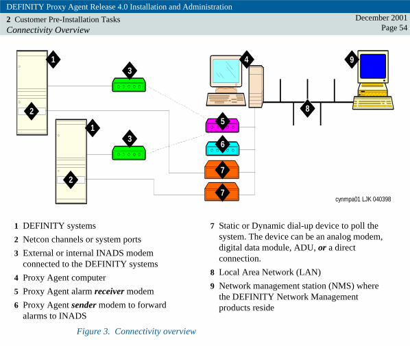
Figure 3. Connectivity overview
1 DEFINITY systems
2 Netcon channels or system ports
3 External or internal INADS modem connected to the DEFINITY systems
4 Proxy Agent computer
5 Proxy Agent alarm receiver modem
6 Proxy Agent sender modem to forward alarms to INADS
7 Static or Dynamic dial-up device to poll the system. The device can be an analog modem, digital data module, ADU, or a direct connection.
8 Local Area Network (LAN)
9 Network management station (NMS) where the DEFINITY Network Management products reside
cynmpa01 LJK 040398
1
1
4
2
2
9
7
7
8
3
3
5
6

DEFINITY Proxy Agent Release 4.0 Installation and Administration
2 Customer Pre-Installation TasksConnectivity Overview
December 2001Page 55
Alarm stream In Figure 3, the alarm stream between the DEFINITY system and the Proxy Agent contains two dedicated analog modems:
• The INADS modem on the DEFINITY system (callout 3) is usually an internal modem that is integrated on a circuit pack. The Prologix system requires an external INADS modem.
• The Proxy Agent modem that receives the alarm from the DEFINITY system (callout 5)
The alarm stream can also contain a Proxy Agent modem that sends alarms to the INADS or a Trouble Tracker modem. This option is not shown in Figure 3.
Dial-up connections
Figure 3 only shows a permanent dial-up connection between the DEFINITY system and the Proxy Agent (callout 7). You can also add a temporary dial-up connection to cut-through from the Network Management Station (NMS) to the Proxy Agent computer in order to administer the DEFINITY system.
Dial-up connections may use the public network to connect the Proxy Agent computer to the DEFINITY system.
Analog dial-up connections
Analog dial-up connections to the DEFINITY system require modem pooling on the system.

DEFINITY Proxy Agent Release 4.0 Installation and Administration
2 Customer Pre-Installation TasksConnectivity Overview
December 2001Page 56
Multiple dial-up connections
Multiple dial-up connections allow simultaneous connections to the DEFINITY system for administration. Administration terminals can be the Proxy Agent computer or any other type of administration terminals.
• The DEFINITY G3r systems allow up to 8 simultaneous administration logins on the system. Only 5 administration commands can be used at one time.
• The DEFINITY G3i V4 systems allow up to 3 simultaneous administration logins.
• The DEFINITY G3i V5 systems allow up to 5 simultaneous administration logins. Only 1 administration command can be used at a time.
• IP600 systems allow up to 10 simultaneous administration logins. Only 1 add/change/remove command can be used at a time.
• DEFINITY One allows up to 10 simultaneous administration logins. Only 1 add/change/remove command can be used at a time.
See also Refer to the DEFINITY product documentation for more information about multiple dial-up connections and administration of the system.

DEFINITY Proxy Agent Release 4.0 Installation and Administration
2 Customer Pre-Installation TasksData Communication Hardware
December 2001Page 57
Data Communication HardwareCustomers must use only communication hardware that is certified by Avaya. Customers must also follow the Avaya certified diagrams to configure the hardware connections.
Circuit Packs The following table matches the communication device and the line type to appropriate the circuit pack.
Note: The TN numbers for the circuit packs are for use in the U.S.A. Other users can refer to the DEFINITY ECS System Description or check with their Avaya representative for more information about the correct circuit pack.
Table 4. Circuit pack selection
Communicate Device Connection Type Circuit Pack
Any supported modem Analog TN746 and TN742
Data modules 7400B and 7400B+ Digital TN754
Data module 8400B+ Digital TN2181 or TN2224
ADU Data TN726B
CLAN Network TN799

DEFINITY Proxy Agent Release 4.0 Installation and Administration
2 Customer Pre-Installation TasksData Communication Hardware
December 2001Page 58
Hardware requirements
The connections between the DEFINITY system and the Proxy Agent computer require the following types of hardware:
• Communication devices including:
– Analog modems
– Digital data modules (7400A, 7400B, 7400B+, or 8400B+),
– Asynchronous Data Units (ADUs)
– Direct connections
– TCP/IP connections
• House wiring and cables for the LAN
• Gender changers between the connections
The following table lists hardware requirements for a public or private network.
Table 5. Hardware requirements for network connections
Network Type
Communication Device
Distance from DEFINITY system
Hardware Requirements
Public Any supported modem
Unlimited Modem pooling on the DEFINITY system
Private Digital data module
Within 5000 feet A port on a digital board (TN754 in the U.S.A.)
ADU Within 2000 feet A port on a dataline board (TN726E in the U.S.A.)

DEFINITY Proxy Agent Release 4.0 Installation and Administration
2 Customer Pre-Installation TasksData Communication Hardware
December 2001Page 59
Note: If you are connecting to a DEFINITY One or IP600 system, no additioanl hardware is required. The DEFINITY Proxy Agent will telnet directly into your system.
Figure The following figure shows hardware for communication devices.
Figure 4. Hardware for communication devices
1 DEFINITY system with circuit packs: TN754C, TN2181, and TN2224
2 Site-specific network connection
3 Communication device that is either an analog modem, a digital data module, or an ADU with a moss adapter
4 Serial I/O modular adapter and cable that connects the device to a serial port on the Proxy Agent computer
5 Proxy Agent computer
cynmpa02 LJK 040398
1
2
34
5

DEFINITY Proxy Agent Release 4.0 Installation and Administration
2 Customer Pre-Installation TasksCables for Communication Devices
December 2001Page 60
Cables for Communication DevicesThe figures in this section illustrate the cable connections for the various communication devices, including:
• "Cable connections for local analog modems" on page 61
• "Cable connections for remote analog modems" on page 62
• "Cable connections for digital data modules" on page 63
• "Cable connections for an ADU with a moss adaptor" on page 64
The type of DEFINITY system does NOT affect the cabling for communication devices.
See also Refer to the documentation from the vendor to:
• Install the correct cables to connect a modem to the computer
• Install the port card hardware and software on the computer

DEFINITY Proxy Agent Release 4.0 Installation and Administration
2 Customer Pre-Installation TasksCables for Communication Devices
December 2001Page 61
Figure The following figure shows the cable connections for local analog modems:
Figure 5. Cable connections for local analog modems
1 DEFINITY system with modem pooling
2 Analog line circuit pack on the DEFINITY system
3 B25A cable with connectors
4 Cross-connection at main distribution frame
5 103A or wall jack
6 RJ11 cable to the analog modem
7 Analog modem
8 Serial I/O modular adapter and cable that connects the device to a serial port on the Proxy Agent computer
9 Proxy Agent computer
cynmpa03 LJK 040698
1
23
45
6 89
7

DEFINITY Proxy Agent Release 4.0 Installation and Administration
2 Customer Pre-Installation TasksCables for Communication Devices
December 2001Page 62
Figure The following figure shows the cable connections for remote analog modems:
Figure 6. Cable connections for remote analog modems
1 103A or wall jack
2 RJ11 cable to the modem
3 Analog modem
4 Serial I/O modular adapter and cable that connect the device to a serial port on the Proxy Agent computer
5 Proxy Agent computer
6 Analog public or private network
cynmpa04 LJK 040398
2
1
43
5
6

DEFINITY Proxy Agent Release 4.0 Installation and Administration
2 Customer Pre-Installation TasksCables for Communication Devices
December 2001Page 63
Figure The following figure shows the cable connections for digital data modules and maximum distance between systems:
Figure 7. Cable connections for digital data modules
1 DEFINITY system
2 Digital line circuit pack on the DEFINITY system
3 B25A cable with connectors
4 Cross-connection at main distribution frame
5 103A or wall jack
6 D82-87 cable to the digital data module
7 Digital data module
8 Serial I/O modular adapter and cable that connects the device to a serial port on the Proxy Agent computer
9 Proxy Agent computer
10 Maximum of 5000 feet between the DEFINITY system and the data module
11 Maximum of 50 feet between the data module and the Proxy Agent computer
cynmpa05 LJK 040398
1
23
45
67
89
10 11

DEFINITY Proxy Agent Release 4.0 Installation and Administration
2 Customer Pre-Installation TasksCables for Communication Devices
December 2001Page 64
Figure The following figure shows the cable connections for an ADU with moss adaptor and maximum distance between systems:
Figure 8. Cable connections for an ADU with a moss adaptor
1 DEFINITY system
2 Digital line circuit pack on the DEFINITY
3 B25A cable with connectors
4 Cross-connection at main distribution frame
5 103A or wall jack
6 D82-87 cable to the digital data module
7 ADU
8 Moss adaptor
9 Serial I/O modular adapter and cable that connects the device to a serial port on the Proxy Agent computer
10 Proxy Agent computer
11 Maximum of 2000 feet between the DEFINITY system and the data module
12 Maximum of 50 feet between the data module and the Proxy Agent computer
cynmpa10 LJK 040698
1
23
45
6
8
910
11 12
7

DEFINITY Proxy Agent Release 4.0 Installation and Administration
2 Customer Pre-Installation TasksCables for Communication Devices
December 2001Page 65
The following figure shows an example of the network configuration over IP between a DEFINITY system and an NMS network server.
Figure 9. Network over IP configuration
1 DEFINITY system with CLAN circuit pack
2 Internet connection (LAN or WAN)
3 UNIX Network server where the DEFINITY Network Management (DNM) product resides. The server can run:
• OpenView on Sun Solaris or HP-UX;
• NetView on AIX
• HP-UX or AIX stand-alone

DEFINITY Proxy Agent Release 4.0 Installation and Administration
2 Customer Pre-Installation TasksComplete the PA001 Form
December 2001Page 66
Complete the PA001 FormThe Technical Services Center (TSC) requires all U.S.A. and Canadian customers to register their systems with the TSC. Customers must complete the PA001 Administration Request and fax the form to the TSC.
International customers
International customers must work with their local service organizations to plan and install their systems and software.
International customers must complete the PA001 Administration Request and fax the form to the Tier IV Registry. Instructions are on the Fax Cover Sheet.
The local service organization should also fax the completed PA001 form to ITAC.
Updates to the PA001 form
Customers only need to complete the portions of the form that pertain to the upgrades or changes to their systems and fax those pages to the TSC.
Customers must update the PA001 form whenever they:
• Upgrade the system hardware and software
• Change or upgrade the network and Network Management System (NMS) platform
• Add, delete, or change data for the managed nodes or communication devices
Customers can print the current version of the PA001 form directly from the Proxy Agent CD-ROM for this release.

DEFINITY Proxy Agent Release 4.0 Installation and Administration
2 Customer Pre-Installation TasksInstall the UnixWare Operating System
December 2001Page 67
Install the UnixWare Operating SystemCustomers are solely responsible for the following requirements:
• Procure and set up the UnixWare-certified hardware for the Proxy Agent computer
• Install and configure the UnixWare operating system.
! CAUTION:Avaya does not install, support, or maintain the UnixWare operating system or other vendor hardware and software products.
UnixWare Upgrade Patches
Users must verify which release of UnixWare is installed on the Proxy Agent computer. Refer to CHANGE HARDWARE screen.
Then execute one of the following options:
• If UnixWare 7.0 is installed, install the UnixWare 7.1.1 upgrade patch from the Caldera web site. Refer to "Vendor References" on page 18 for the web address.
• If UnixWare 2.1.0 or later is installed, install UnixWare 2.1.3.
• If a release of UnixWare prior to release 2.1.0 is currently installed, then you must complete a Destructive installation of the UnixWare 2.1.3 or the 7.1.x operating systems. Non-destructive upgrades of the UnixWare 2.0.x and earlier versions have been error-prone.

DEFINITY Proxy Agent Release 4.0 Installation and Administration
2 Customer Pre-Installation TasksUnixWare Installation Tasks
December 2001Page 68
UnixWare Installation Tasks Customers must complete the following tasks to install the UnixWare operating system:
1 Set up the UnixWare-certified Proxy Agent computer hardware:
• Install the network interface card
• Install the host bus adapter
• Install the serial I/O port cards
2 Install the UnixWare Release 2.1.3 or 7.1.x on the Proxy Agent computer.
3 Add the following packages to UnixWare Release 2.1.3:
• bsdcompat -- BSD compatibility
• bkrs -- Extended backup and restore
• ccs -- Optimizing C compilation system
• cmds -- Advanced commands
• oam -- Operations, administration & maintenance
• terminf -- Terminfo utilities
• manpages -- Traditional manual pages
4 Delete the following packages from UnixWare Release 2.1.3:
• nwnet -- NetWare Networking
• nuc -- NetWare UNIX Client
• nwsup -- NetWare Integration Kit

DEFINITY Proxy Agent Release 4.0 Installation and Administration
2 Customer Pre-Installation TasksUnixWare Installation Tasks
December 2001Page 69
5 Disable the plug-n-play cards for all add-on interface cards installed on the Proxy Agent computer. Unixware 2.1.3 and 7.1.1 do not support plug and play hardware. Some plug-n-play cards use interrupts or I/O addresses that have been previously assigned to other hardware devices and drivers. Unless you disable the plug-n-play, you may experience installation difficulties.
There are no additional packages to install or delete for UnixWare 7.1.1. for use with DEFINITY Proxy Agent. For any updates to this information, please consult the Project Provisioning Package for DEFINITY Network Management and DEFINITY Proxy Agent.
UNIX backup Avaya strongly recommends that users backup the UNIX system at least twice a month.
• For tape drive backups, perform a full system backup and then reboot the UNIX system.
• For backups on floppy diskettes, backup the /usr/g3-ma directory and then reboot the UNIX system.

DEFINITY Proxy Agent Release 4.0 Installation and Administration
2 Customer Pre-Installation TasksAdminister the Communication Devices
December 2001Page 70
Administer the Communication DevicesCustomers must complete the following tasks to connect the communication devices:
1 Administer the TCP/IP connections:
• Configure the Ethernet/Token Ring interface
• Set up the IP address in the Hosts file• Test the TCP/IP connection
2 Verify that the routing table contains the default router command
3 Configure Dial-In access to the DEFINITY system for system management access. This may entail Data Modules, Modem Pools, and/or System Port/ Netcon Channels and Hunt Groups.
• On DEFINITY G3r systems, the system port is an administered resource and requires a data board and pdata board. You execute the following commands to administer the system port:
– Execute the add data-module command to assign the system port to an extension.
– Execute the add hunt-group command to add the system port extension as a member of a hunt group.
• On DEFINITY G3i systems, the netcon port is an internal channel that you can assign as a port. You execute the following commands to administer the netcon port:
– Execute the add data-module command to assign the netcon port to an extension.
– Execute the add hunt-group command to add the netcon port extension as a member of a hunt group.

DEFINITY Proxy Agent Release 4.0 Installation and Administration
2 Customer Pre-Installation TasksAdminister the Communication Devices
December 2001Page 71
4 Execute the add station command to administer the following devices:
• Analog line
• Digital voice and data module
• Digital data-only module (may require modem pooling)
• ADU
5 To forward alarms to INADS or to the Proxy Agent for DEFINITY G3 systems, execute the command change system-parameters maintenance and enter the phone number in the OSS Telephone Number field 1 or 2.
6 The DEFINITY ECS systems are set up to forward alarms to INADS. To also set up the Proxy Agent to receive and forward alarms, then
• Enter the phone numbers for both the INADS and Proxy Agent on the form entitled Maintenance-Related System Parameters.
• Execute the command change system-parameters maintenance, then enter the telephone number for the Proxy Agent in one of the OSS Telephone Number fields.
7 To set up the Proxy Agent to receive alarms from other types of supported system, enter the phone number for the Proxy Agent alarm receiver devices on the systems.

DEFINITY Proxy Agent Release 4.0 Installation and Administration
2 Customer Pre-Installation TasksAdminister Security Options
December 2001Page 72
Administer Security OptionsCustomers must complete the following tasks to administer the security options:
1 For DEFINITY systems, execute the following commands:
• add login [name]
• change permissions [login name], then
– Enter Y in the fields entitled: Display Admin and Maint Data and System Measurements.
– Set the permissions to “browse only” or “non-superuser read-only”

DEFINITY Proxy Agent Release 4.0 Installation and Administration
2 Customer Pre-Installation TasksAdminister Security Options
December 2001Page 73
Figure 10. Browser Change Permissions SNMP

DEFINITY Proxy Agent Release 4.0 Installation and Administration
2 Customer Pre-Installation TasksAdminister Security Options
December 2001Page 74
– Disable the “password-aging” feature
– All other fields on the form should be set to No
• Fields for basic DPA use no SNMP Sets:
– Display Admin and Maintenance Data = y
– System Measurements = y
• Busy/Release use of DPA w/snmp sets and above plus:
– Maintain Stations = y
– Maintain Trunks = y
– Maintain System = y
– Maintain Switch Circuit packs = y
– Maintain Process circuit packs = y
2 For other types of supported systems, access the appropriate forms and administer the following security options:
• Set the permissions to “browse only,” unless the users wants to be able to do busy-outs/releases and set DEFINITY time via SNMP. SNMP sets requires Maintenance and Administrator permissions.
• Disable the “password-aging” feature

DEFINITY Proxy Agent Release 4.0 Installation and Administration
2 Customer Pre-Installation TasksChange the DIP Switch Settings
December 2001Page 75
Change the DIP Switch SettingsCustomers may need to change the dip switch settings for each communication device that is connected to the Proxy Agent.
The tables in this section contain the dip switch settings for the following data communications devices:
• AT&T 2224CEO analog modem
• 7400B/B+ data module
• Port data module (PDM)
• MPDM
Settings for AT&T 2224CEO ModemsFor the AT&T 2224 CEO analog modem, change the dip switches on the front panel of the modem:
1 Set dip switch #1 to the up position
2 Set dip switch #6 to the up position
3 All other dip switches must be in the down position
Note: The AT&T 2224CEO modem is not certified for Proxy Agent modems that send alarms to INADS or a Trouble Tracker.

DEFINITY Proxy Agent Release 4.0 Installation and Administration
2 Customer Pre-Installation TasksSettings for 7400B/B+ Data Modules
December 2001Page 76
Settings for 7400B/B+ Data Modules For 7400B/B+ data modules, change the dip switches to match the settings in the following table.
Table 6. Dip switch settings for 7400B/B+ modules
Data Module Dip Switch Setting
Stand alone, data-only:
• 7400B
• 7400B+
• Change the SW1 dip switch to the on position
• All other dip switches should be in the off position
Voice-and-data:
• 7400B
• 7400B+
All dip switches should be in the off position. This module requires a connection to a digital phone and is rarely used with the Proxy Agent.

DEFINITY Proxy Agent Release 4.0 Installation and Administration
2 Customer Pre-Installation TasksSettings for PDMs
December 2001Page 77
Settings for PDMs For PDMs, change the dip switches to match the settings in the following table.
Note: For 9600 baud, the dip switch must be set to the ON position.
Table 7. Dip switch settings for PDMs
Dip Switch Setting Dip Switch Setting
LOW OFF PRTY OFF
300 OFF I/OD OFF
1200 OFF DMLL OFF
2400 OFF MKBY OFF
4800 OFF SPARE (none)
9600 ON SIGLS ON
19.2 OFF AANS ON
SPARE (none) DL-HI OFF
SPARE (none) CN25 OFF
SPARE (none) CN18 OFF
HDX OFF RL21 OFF
SYNC OFF CI12 OFF
(1 of 2)

DEFINITY Proxy Agent Release 4.0 Installation and Administration
2 Customer Pre-Installation TasksSettings for PDMs
December 2001Page 78
INT OFF PRTY OFF
DISC OFF I/OD OFF
KYBD ON DMLL OFF
Table 7. Dip switch settings for PDMs
Dip Switch Setting Dip Switch Setting
(2 of 2)

DEFINITY Proxy Agent Release 4.0 Installation and Administration
2 Customer Pre-Installation TasksSettings for MPDMs
December 2001Page 79
Settings for MPDMs For MPDMs, change the dip switches to match the settings in the following table.
Note: For 9600 baud, the dip switch must be set to the ON position.
Table 8. Dip switch settings for MPDMs
Dip Switch Setting Dip Switch Setting
LOW OFF SYNC ASYN
300 OFF INT EXT
1200 OFF DISC OFF
2400 OFF KYBD OFF
4800 OFF PRTY OFF
9600 ON I/OD OEN
19.2 OFF DMLL OFF
56K OFF MKBY OFF
64K OFF SPARE (none)
TRDK OFF SIGLS OFF
HDX FDX AANS OFF
LOW OFF SYNC ASYN

DEFINITY Proxy Agent Release 4.0 Installation and Administration
2 Customer Pre-Installation TasksSet the Interface for 7400A Modules
December 2001Page 80
Set the Interface for 7400A ModulesFor the 7400A data modules, customers must set the interface on the device before you connect the device to the DPA computer.
1 On the front panel of the module, set the interface control:
• Press Next/No until the system displays the prompt: SET INTERFACE?
• Press Enter/Yes
If the SET INTERFACE? prompt does NOT display, then
• Continuously press Next/Yes until the system displays the SET INTERFACE? prompt
• Press Enter/Yes
Result: The system displays the prompt: INT = AT COMM?
2 Press Enter/Yes to exit.
Result: The data module resets the interface and performs a self test.

DEFINITY Proxy Agent Release 4.0 Installation and Administration
2 Customer Pre-Installation TasksExecute the Platform Acceptance Test
December 2001Page 81
Execute the Platform Acceptance TestThe customer and a TSC engineer work together to execute the Platform Acceptance Test.
Use the Platform Acceptance Test to:
• Verify that the Network Management Station (NMS) is functioning
• Verify that the correct version of the UnixWare operating system is installed
• Verify that the modem connection is functioning
Required materials
Customers need the following materials and information:
• Root login and password
• PA001 form
Procedure Complete the following procedure to execute the Platform Acceptance Test.
1 The user calls the TSC to set up the test. For the TSC Technical Support phone number, refer to "Avaya References" on page 15.
2 To begin the test, ping the NMS from the Proxy Agent computer.
At the UNIX prompt:
• Type /usr/sbin/ping [nms_name]
• Press ENTER
Result: The system displays the message: [nms_name] is alive

DEFINITY Proxy Agent Release 4.0 Installation and Administration
2 Customer Pre-Installation TasksExecute the Platform Acceptance Test
December 2001Page 82
3 Verify the release number for the UnixWare software.
At the UNIX prompt:
• Type uname -v
• Press ENTER
Result: The system displays the UnixWare release number 2.1.3 or 7.1.x depending on the configuration of your system.
4 Hook-up a modem to a serial card port on the Proxy Agent. For the UNIX device name, refer to the Devices section on the PA001 form. In UNIX, the correct device name must be entered.
At the UNIX prompt, connect the device:
• Type cu -s 9600 -l /dev/[device name]
• Press ENTER
Result: The system displays the message: Connected
5 Identify the port for the device:
• Type #echo “Direct tty1a1,M - Any direct_modem”>> /etc/uucp/Deviceswhere tty1a1 is the correct port for the device you hooked up in the previous step. This could be another port or even a different format depending on the type of I/O card you are using.
• Press ENTER
6 At the UNIX prompt, verify the connection:
• Type at&f
• Press ENTER

DEFINITY Proxy Agent Release 4.0 Installation and Administration
2 Customer Pre-Installation TasksExecute the Platform Acceptance Test
December 2001Page 83
Result: The system displays the message: OK
7 At the UNIX prompt, disconnect the modem:
• Type ~.
• Press ENTER
Example: Type: tilde (~) period (.) with no space between them.
Result: The system displays the message: Disconnected
8 At the completion of the test, go to the Proxy Agent section of the PA001 form and complete the following field:
Platform Acceptance Test completed by:
• In the Name field, enter the name customer’s employee who completed the test with the TSC
• In the Date field, enter the date of the test
9 Complete the fields on the Fax Cover Sheet. Then, fax the completed PA001 form to TSC at the telephone number on cover sheet.

DEFINITY Proxy Agent Release 4.0 Installation and AdministrationDecember 2001
Page 843 3Installing or Upgrading DPA
IntroductionThis chapter contains the procedures to install or upgrade DEFINITY Proxy Agent (DPA) Release 4.0.
Pre-installation tasks
Customers must complete all of the pre-installation tasks before you install or upgrade DPA. Refer to chapter 2, "Customer Pre-Installation Tasks" on page 52.
Post installation options
The system administrator (root user) can execute the maintenance options listed below after the Proxy Agent has been installed:
• "Add New Devices" on page 319
• "Change Settings for SNMP Access" on page 320
User documentation
The installation script for this release automatically copies the DPA documentation to the avayadoc directory.
Users can access the documentation only from the UnixWare Desktop. Refer to the procedure to "Access the User Documentation" on page 139.

DEFINITY Proxy Agent Release 4.0 Installation and Administration
3 Installing or Upgrading DPAInstallation Checklists
December 2001Page 85
Installation ChecklistsThe installation checklists contain the tasks that installation technicians must complete to install the new Proxy Agent 4.0 or upgrade to the Proxy Agent 4.0.
Installation ChecklistInstallers must execute the installation tasks listed below in the order presented.
1 Verify that all tasks in Chapter 2, "Customer Pre-Installation Tasks" have been completed.
2 Call the Technical Services Center (TSC) to verify that the procedure to "Execute the Platform Acceptance Test" on page 81 has been completed.
3 Assemble the required materials and information, including:
• Root login and password
• Default login ID and password or ASG secret key for new DEFINITY systems
• New password for the g3maadm login
• Completed PA001 form
• CD-ROMs DEFINITY Network Management Proxy Agent Release 4.0
• Printed copy of the DNM 4.0 Proxy Agent User Documentation for Installation and Administration (this book)
• Technical Services Center (TSC) number: 1-800-242-2121, ext. 8-6767

DEFINITY Proxy Agent Release 4.0 Installation and Administration
3 Installing or Upgrading DPAInstallation Checklist
December 2001Page 86
4 Execute one of the installation procedures (a, b, or c) listed below:
a "Installing DPA" on page 97.
b "Upgrading from DPA 3.0 and Later" on page 107
c "Upgrading from DPA 2.0.2 and Earlier" on page 117
5 Complete the procedure to "Administer the Network Managers" on page 163.
6 Complete the procedure to "Administer the Default Location" on page 174.
7 Complete the procedure to "Administer the Alarm Device" on page 181.
8 Complete the procedure to "Administer the Filter Sets" on page 202.
9 Complete the procedure to "Administer the Default Login" on page 218
10 Complete the procedure to "Administer the Managed Nodes" on page 248
11 Complete the tasks on the "Technical Verification Checklist" on page 87.
12 Complete the tasks on the "Customer Acceptance Checklist" on page 88.

DEFINITY Proxy Agent Release 4.0 Installation and Administration
3 Installing or Upgrading DPATechnical Verification Checklist
December 2001Page 87
Technical Verification ChecklistThe installation technician and the engineer at the Technical Services Center (TSC) must complete the post installation tasks below to insure that DPA is properly administered and functioning.
1 Verify that the customer completed and faxed PA001 form to the TSC.
2 Verify that the TSC has updated the System Management database with the current data from the PA001 form.
3 Verify that all of the tasks on the "Installation Checklist" on page 85 have been completed.
4 Verify that the Proxy Agent is connected to each managed node.
5 If “alarm forwarding” is active, then check the ALARM DEVICES screen to validate that “alarm forwarding” is properly functioning:
• Verify that the Proxy Agent can receive alarms from each managed node and forward alarms to INADS
• Verify that INADS received each alarm that was sent to them
• Verify that INADS created a TSC-SS ticket for each alarm
Refer to "Administer the Alarm Device" on page 181.
6 If the DEFINITY system is set up to send alarms, verify that both INADS and the Proxy Agent receive them.
7 Verify that the TSC login and password for root2 and ncsc have been administered. Avaya uses these logins to conduct maintenance tasks.

DEFINITY Proxy Agent Release 4.0 Installation and Administration
3 Installing or Upgrading DPACustomer Acceptance Checklist
December 2001Page 88
Customer Acceptance ChecklistThe engineer at the TSC and the customer must complete the post installation tasks below to insure the that customer can operate DPA and accepts the installation as “complete.”
1 Verify that the customer can log in to the Proxy Agent from both the UNIX shell or the UnixWare Desktop. Refer to the procedures below:
• "Log in from the UNIX Shell" on page 132
• "Log in from the Desktop" on page 134
2 Verify that the customer can view the Proxy Agent User Documentation from the UnixWare Desktop. Refer to "Access the User Documentation" on page 139.
3 Verify that the customer can start the Proxy Agent, display the STATUS screen, and stop the Proxy Agent. Refer to the procedures below:
• "Start the Proxy Agent" on page 149
• "Display of the Status Screen" on page 150
• "Stop the Proxy Agent" on page 156
4 Review the Proxy Agent application screens with the customer. Refer to chapters 4 through 14.
5 Verify that the customer has changed the root and g3maadm logins.

DEFINITY Proxy Agent Release 4.0 Installation and Administration
3 Installing or Upgrading DPAUnderstanding the Installation Prompts
December 2001Page 89
Understanding the Installation PromptsThe installation script for this release has been revised in order to simplify the process and to make the installation of DPA more automatic.
PA001 form The completed PA001 Administration Request form contains most of the information that is specific to the customer’s system. Installers must refer to the various sections on the PA001 form in order to enter the information that is requested at the installation prompts.
Default options The sections below describe the prompts in the order presented in the installation script. Avaya strongly recommends that installers select the default options where appropriate. The default options allow users to maintain consistency when upgrading to new releases. The installation script overwrites previous settings during the installation process.
Directory PromptThe directory prompt requests the installer to define the directory where the Proxy Agent software will reside on the system.
Installers can enter one of the options below:
a Accept the default /usr/g3-ma directory (recommended)
b Enter a different directory path (not recommended)

DEFINITY Proxy Agent Release 4.0 Installation and Administration
3 Installing or Upgrading DPARAM Megabytes Prompt
December 2001Page 90
RAM Megabytes PromptThe RAM megabytes prompt requests the installer to enter the megabytes of RAM on the Proxy Agent stand-alone computer. If the number is more than 128 megabytes, the installation script makes modifications to the kernel boot file.
The PA001 form contains the system information in the Proxy Agent section.
SNMP Polling PromptFor the Proxy Agent to poll the supported systems and create Enterprise-specific traps installers should enable SNMP Polling. The installation script automatically enables SNMP Traps, since both options are required for SNMP polling.
Installers can choose to disable SNMP polling if the Proxy Agent is used only as an alarm notification device and the DEFINITY Network Management product is not used.
SNMP Traps PromptIf SNMP Polling is disabled, then the installation script displays the prompt to enable or disable SNMP Traps.
Installers should enable SNMP Traps if they want to receive SNMP traps only. In this release, if SNMP Polling is disabled and SNMP Traps are enabled, then the Proxy Agent allows installers to administer up to 600 managed nodes for each Proxy Agent. This option reduces the load on the Proxy Agent and requires a less powerful computer to manage a larger number of supported systems.
Installers also have the option to disable SNMP Traps if the Proxy Agent is only used for alarm processing.
DEFINITY Proxy Agent Release 4.0 Installation and Administration
3 Installing or Upgrading DPASNMP Set Capability Prompt
December 2001Page 91
SNMP Set Capability PromptDuring the Proxy Agent installation, installers can also enable or disable the SNMP Set Capability.
This feature allows users on the NMS server to managed the tasks listed below from the DEFINITY Network Management product:
• Busy Out/Release boards, ports, trunk groups, and trunks
• Set DEFINITY system date and time
! SECURITY ALERT:Due to security limitations in SNMP, installers should enable the SNMP Set Capability only if the Proxy Agent is behind a fire wall.
Password PromptsFor new installations only, the password prompts require the installer to enter the g3maadm login password to allow access to the Proxy Agent user interface.
Function PromptThe customer may administer four types of communication devices on the serial I/O subsystem to perform the four functions required by the Proxy Agent:
• Remote maintenance access
• Product access
• Receive alarms
• Send alarms

DEFINITY Proxy Agent Release 4.0 Installation and Administration
3 Installing or Upgrading DPAFunction Prompt
December 2001Page 92
IP-based devices do not need to be configured. They are automatically configured by the DEFINITY Proxy Agent installation software.
Refer to the "Serial I/O Subsystem" on page 95 for examples of naming formats for the different types of the subsystems.
If the customer administers additional devices, then the PA001 form also should contain the information for those devices.
The installation script runs the Modem Setup program and displays the UNIX device name (/dev/ttyxxx) for all devices administered on the serial I/O subsystem and displays the prompt to select the function for that device.
The following is an example of the device name (/dev/ttysa1) and function prompt:
UNIX device name: /dev/ttysa1:
Select the function for this device:
[M] Maintenance Remote Access (TSC/ITAC)
[P] Product Access (default)
[R] Receive Alarms
[S] Send Alarms
Or, select one of the options below:
[N] Next Device (skip this one)[X] Exit Modem Setup and continue the installation
Enter the device function or another option [default=P]:

DEFINITY Proxy Agent Release 4.0 Installation and Administration
3 Installing or Upgrading DPADevice Type Prompt
December 2001Page 93
Installers must execute the appropriate option for each device detected by the installation script. Installers can exit the Modem Setup program only from the function prompt.
Device Type PromptThe installation script then displays the second prompt for the device type of the device name (/dev/ttysa1) shown in the previous prompt. The device type prompt refers to the make and model of the device.
The installation script displays different lists in the device type prompt that are based on the function that the installer selected for this device.
The following is an example of the device type prompt for the remote maintenance function:
UNIX device name: /dev/ttysa1:
Select the device type for the maintenance remote access function:
[1] 3710 AT&T Dataport
[2] 3715 AT&T Dataport Express
[3] US Robotics Sportster 33.6 Kbps
[4] Other (manually)
Or select the option below:
[N] Next Device (skip this one)
Enter the device type or another option[default=1]:

DEFINITY Proxy Agent Release 4.0 Installation and Administration
3 Installing or Upgrading DPAReboot Prompt
December 2001Page 94
Installers must execute the appropriate option for each device assigned to the Proxy Agent.
If the device type is not on the list, then the installer should enter the number for Other (4) at the prompt. The system administrator must manually administer a different type of modem in the Devices file after the installation is complete.
The installation script continues to display the next device name and function prompt for all devices on the serial I/O subsystem. When all the devices on the PA001 form have been administered, then the installer exits the Modem Setup program from the function prompt.
Reboot PromptThe reboot prompt is the last prompt in the installation script. Installations must enter the shutdown command to reboot the system before they execute the procedures to administer the Proxy Agent.

DEFINITY Proxy Agent Release 4.0 Installation and Administration
3 Installing or Upgrading DPASerial I/O Subsystem
December 2001Page 95
Serial I/O SubsystemGenerally, the devices are connected to serial input/output (I/O) subsystems, such as the ones listed below:
• Equinox XP
• Equinox SST
• Computone RackPort 3
• Specialix SIO
• Standard COM Ports /dev/tty00 - /dev/tty03
The UNIX device name (/dev/ttyxxx) is based on the different numbering formats used by each subsystem (ttyxxx) as described below.
Subsystem numbering format
A subsystem usually consists of several “bricks” linked together through a plug-in module. Each port on the brick has a different port number (ttyxxx). In addition, each type of subsystem has a different numbering format for the ports on each brick.
The table below shows the numbering format for the serial I/O subsystems listed above. The number of “bricks” supported by each subsystem will vary.

DEFINITY Proxy Agent Release 4.0 Installation and Administration
3 Installing or Upgrading DPASerial I/O Subsystem
December 2001Page 96
* [n] represents the next port number on the brick
Table 9. Serial I/O Subsystems
Brick Number Port Number Equinox XP Equinox SST Computone RackPort 3
Specialix SIO
Brick 1
Port1
Port2
Port[n] *
ttysa1
ttysa2
ttysa[n]
tty1a1
tty1a2
tty1a[n]
ttyS01
ttyS02
ttyS0[n]
ttyA1
ttyA2
ttyA[n]
Brick 2
Port1
Port2
Port[n]
ttysb1
ttysb2
ttysb[n]
tty1b1
tty1b2
tty1b[n]
ttyS016
ttyS017
ttyS0[n]
ttyB1
ttyB2
ttyB[n]
Brick 3
Port1
Port2
Port[n]
ttysc1
ttysc2
ttysc[n]
tty1c1
tty1c2
tty1c[n]
ttyS031
ttyS032
ttyS0[n]
ttyC1
ttyC2
ttyC[n]
Brick 4
Port1
Port2
Port[n]
n/a
n/a
n/a
tty1d1
tty1d2
tty1d[n]
ttyS046
ttyS047
ttyS0[n]
ttyD1
ttyD2
ttyD[n]

DEFINITY Proxy Agent Release 4.0 Installation and Administration
3 Installing or Upgrading DPAInstalling DPA
December 2001Page 97
Installing DPAThis section contains the procedures to install DPA Release 4.0 product on the Proxy Agent stand-alone computer.
Before installers begin the installation procedures, verify the completion of the tasks listed below:
• Verify that all tasks in Chapter 2, "Customer Pre-Installation Tasks" have been completed.
• Review the "Installation Checklist" on page 85 and complete the tasks in the order listed in the checklist.
• Read the entire section entitled "Understanding the Installation Prompts" on page 89. This section explains how to respond to the prompts in the installation script.
Required materials
Installers need the materials and information listed below:
• Root login and password
• New password for the g3maadm login
• Completed PA001 Administration Request form
• CD-ROM entitled DEFINITY Network Management Proxy Agent Release 4.0

DEFINITY Proxy Agent Release 4.0 Installation and Administration
3 Installing or Upgrading DPAInstalling DPA
December 2001Page 98
New installation procedure
Complete the procedure below to install DPA Release 4.0.
1 Execute the tasks below:
• Request all users to log off the system.
• Close all open windows and applications.
2 At the UNIX login prompt, login as the root user:
• Type [root login]
• Press ENTER
3 At the Password prompt,
• Type [root password]
• Press ENTER
4 At the Display Desktop? y/n prompt,
• Type N (no)
• Press ENTER
Result: The system displays the UNIX prompt.
5 At the UNIX prompt (#), start the installation process:
• Type pkgadd -d cdrom1 DG3PA
• Press ENTER
Result: The system displays the name of the package and the prompt:
Insert CD into CD-Rom Drive. Type [go] when ready or [q] to quit (default=go):

DEFINITY Proxy Agent Release 4.0 Installation and Administration
3 Installing or Upgrading DPAInstalling DPA
December 2001Page 99
6 Insert the CD-ROM entitled DEFINITY Network Management Proxy Agent Release 4.0, into the CD-ROM drive.
At the UNIX prompt,
• Type go
• Press ENTER
Result: The system displays the prompt: Strike ENTER when ready or ESC to stop.
7 At the UNIX prompt, press ENTER
Result: The system installs the program, which takes a few moments.
8 RAM Megabytes Prompt. The system displays the prompt:
How much RAM does the Proxy Agent serve have in it? If it is more than 128 Megabytes, then a modifications must be made to the kernel boot file.
How many megabytes of RAM?
On the PA001 form, go to the Proxy Agent section, then refer to the Random Access Memory (RAM) field for the number of megabytes of RAM (MB).
At the UNIX prompt,
• Type the [number] of megabytes of RAM
• Press ENTER
Result: The system modifies the kernel boot file.

DEFINITY Proxy Agent Release 4.0 Installation and Administration
3 Installing or Upgrading DPAInstalling DPA
December 2001Page 100
9 SNMP Polling Prompt. The system displays an explanation of the reasons to enable (default) or disable SNMP Polling. Then, the system displays the current setting and the prompt:
The current setting is SNMP polling ENABLED.
Should SNMP Polling be DISABLED? [n] y:
At the prompt, execute one of the options (a or b) below:
a To enable SNMP polling (default),
– Press ENTER.
– Go to step 11
b To disable SNMP polling,
– Type Y (yes)
– Press ENTER
– Go to step 10
10 SNMP Traps Prompt. If users disabled SNMP polling in step 9, then the system displays an explanation of the reasons to enable (default) or disable SNMP traps. This prompt will not display if users enabled the SNMP Polling because SNMP Traps are required for SNMP Polling.
Then, the system displays the current setting and the prompt:
The current setting is SNMP Traps are ENABLED.
Should SNMP Traps be DISABLED? [n] y:

DEFINITY Proxy Agent Release 4.0 Installation and Administration
3 Installing or Upgrading DPAInstalling DPA
December 2001Page 101
At the prompt, execute one of the options (a or b) below:
a To enable SNMP traps (default),
– Press ENTER
– Go to step 11
b To disable SNMP traps,
– Type Y (yes)
– Press ENTER
– Go to step 12
11 SNMP Set Capability Prompt. If users enabled SNMP Polling in step 9, then the system displays an explanation of the reasons to disable (default) or enable SNMP Set Capability. The SNMP Set Capability allows network managers on the NMS to execute the tasks below from the DEFINITY Network Management product.
• Busy-out and release alarms
• Set the system date and time
Then the system displays a warning and the prompt:
WARNING: If you are not behind a secure firewall, it is strongly suggested that this option be disabled!
The current setting is SNMP Set Capability is DISABLED.
Should SNMP Set Capability be ENABLED? [n]/y:

DEFINITY Proxy Agent Release 4.0 Installation and Administration
3 Installing or Upgrading DPAInstalling DPA
December 2001Page 102
At the prompt, execute one of the options (a or b) below:
a To disable SNMP set capability (default), if the Proxy Agent is not behind a secure fire wall,
– Press ENTER
– Go to step 12
b To enable SNMP set capability, if the Proxy Agent is behind a secure fire wall,
– Type Y (yes)
– Press ENTER
– Go to step 12
Result: The system updates the SNMP access files.
12 Password Prompt. Then the system displays the password fields for the g3maadm login. Type a new g3maadm password in the fields below. Press ENTER after each entry:
New password: xxxxxxRe-enter new password: xxxxxx
Result: The system administers the g3maadm login and the TSC Maintenance accounts, then displays the message:
TSC Maintenance accounts successfully administered.
13 Function Prompt. After this message, the installation script executes the Modem Setup program. The Modem Setup program displays all devices detected on the serial I/O subsystem. Refer to the Devices section of the PA001 form and skip all devices that are not listed on the form.

DEFINITY Proxy Agent Release 4.0 Installation and Administration
3 Installing or Upgrading DPAInstalling DPA
December 2001Page 103
The system displays the first device name from the serial I/O subsystem and the device function prompt for that device:
UNIX device name: /dev/ttyxxx:
Select the function for this device:
[M] Maintenance Remote Access (TSC/ITAC)
[P] Product Access (default)
[R] Receive Alarms
[S] Send Alarms
Or, select one of the options below:
[N] Next Device (skip this one)
[X] Exit Modem Setup and continue the installation
Enter the letter for the device function or another option [default=P]:
Refer to the Devices section on the PA001 form and check the fields, Device Name and Device Function, for this device.
At the prompt, execute one of the options (a or b) below:
a If the device name is on the PA001 form, then
– Type the [letter] that matches the function for this device
– Press ENTER
– Go to step 14

DEFINITY Proxy Agent Release 4.0 Installation and Administration
3 Installing or Upgrading DPAInstalling DPA
December 2001Page 104
b If the device name is not on the PA001 form, then skip this device,
– Type N (Next)
– Press ENTER
– The system displays the device name and function prompt for the next device in the I/O subsystem. Repeat this step to skip every device that is not on the PA001 form.
14 Device Type Prompt. The system displays the device type prompt. The prompt below is an example of the maintenance function. The list varies by the function selected in the previous prompt.
UNIX device name: /dev/ttyxxx:
Select the device type for the maintenance remote access function:
[1] 3710 AT&T Dataport
[2] 3715 AT&T Dataport Express
[3] US Robotics Sportster 33.6 Kbps
[4] Other (manually)
Or select the option below:
[N] Next Device (skip this one)
Enter the number for the device type or another option[default=1]:

DEFINITY Proxy Agent Release 4.0 Installation and Administration
3 Installing or Upgrading DPAInstalling DPA
December 2001Page 105
Refer to the Devices section on the PA001 form and check the Device Type field for this device. At the prompt, execute one of the options (a or b) below:
a If the device name is on the PA001 form, then
– Type the [number] that matches the device type
– Press ENTER
b If the device name is not listed in the prompt, then skip the prompt,
– Type N (Next)
– Press ENTER
Result: The system displays the device name and the device function prompt for the next device in the I/O subsystem.
Note: Repeat steps 13 and 14 to set up all of the of the devices on the PA001 form. Then go to step 15 to exit the Modem Setup program.
15 Exit Modem Setup. To exit the Modem Setup program at a device function prompt,
• Type X (Exit)
• Press ENTER
Result: The system exits the Modem Setup program and displays the message:
Done setting up Devices.
Result: Next, the system continues the installation, lists a series of messages, which takes several minutes. Then, the system displays another message:
Installation of Avaya DEFINITY Proxy Agent (DG3PA) was successful.

DEFINITY Proxy Agent Release 4.0 Installation and Administration
3 Installing or Upgrading DPAInstalling DPA
December 2001Page 106
16 Reboot Prompt. Finally, the system displays the reboot prompt:
Reboot the machine by executing ‘cd /; shutdown -i6 -g0 -y’
At the UNIX prompt,
• Type the shutdown command: cd /; shutdown -i6 -g0 -y
• Press ENTER
Result: The system reboots the computer, which takes several minutes. Then, the system displays the UNIX login prompt.
17 Refer to the "Installation Checklists" on page 85 and complete each procedure in the order listed on the checklist.

DEFINITY Proxy Agent Release 4.0 Installation and Administration
3 Installing or Upgrading DPAUpgrading from DPA 3.0 and Later
December 2001Page 107
Upgrading from DPA 3.0 and LaterThis section contains the procedures to upgrade from DPA 3.0 and later to DPA Release 4.0.
UnixWare upgrade patches
Your system must be running UnixWare Operating System Release 2.1.3 or 7.1.x.
To download the latest patch for the UnixWare Operating System Release 7.1.x, refer to the "Vendor References" on page 18 for the Caldera web address.
! CAUTION:The customer is solely responsible for the installation and maintenance of third-party products. For technical support of these products, the customer must call the vendor. Avaya does not provide support for third-party hardware or software products.
Installation script The Devices section of the PA001 form should contain all of the device names that are assigned to the Proxy Agent.
For upgrades, the installation script only searches for devices that are not currently detected on the I/O subsystem. If the script detects any undefined devices, then the script displays the prompts for those devices.
Please read the entire section entitled "Understanding the Installation Prompts" on page 89. This section explains how to respond to the prompts in the installation script.

DEFINITY Proxy Agent Release 4.0 Installation and Administration
3 Installing or Upgrading DPAUpgrading from DPA 3.0 and Later
December 2001Page 108
Required materials
Installers need the following materials and information:
• Root login and password
• Completed PA001 form
• CD-ROM entitled DEFINITY Network Management Proxy Agent Release 4.0
Upgrade procedure
Complete the procedure below to upgrade DPA 3.0 and later to DPA Release 4.0.
1 Execute the tasks below:
• Request all users to log off the system, if necessary.
• Close all open windows and applications.
• Stop the Proxy Agent if running. Refer to "Stop the Proxy Agent" on page 156
• Log off the system.
2 At the UNIX login prompt, login to the root (/) directory:
• Type [root login]
• Press ENTER
3 At the Password prompt,
• Type [root password]
• Press ENTER
4 At the Display Desktop? y/n prompt,
• Type N (no)
• Press ENTER
Result: The system displays the UNIX prompt.

DEFINITY Proxy Agent Release 4.0 Installation and Administration
3 Installing or Upgrading DPAUpgrading from DPA 3.0 and Later
December 2001Page 109
5 At the UNIX prompt (#), start the installation process:
• Type pkgadd -d cdrom1 DG3PA
• Press ENTER
Result: The system displays the name of the package and the prompt:
Insert CD into CD-Rom Drive. Type [go] when ready or [q] to quit (default=go):
6 Insert the CD-ROM entitled DEFINITY Network Management Proxy Agent Release 4.0, into the CD-ROM drive.
At the UNIX prompt,
• Type go
• Press ENTER
Result: The system displays the prompt: Strike ENTER when ready or ESC to stop.
7 At the UNIX prompt, press ENTER
Result: The system installs the program, which takes a few moments.
8 RAM Megabytes Prompt. The system displays the prompt:
How much RAM does the Proxy Agent serve have in it? If it is more than 128 Megabytes, then a modifications must be made to the kernel boot file.
How many megabytes of RAM?
On the PA001 form, go to the Proxy Agent section, then refer to the Random Access Memory (RAM) field for the number of megabytes of RAM (MB).

DEFINITY Proxy Agent Release 4.0 Installation and Administration
3 Installing or Upgrading DPAUpgrading from DPA 3.0 and Later
December 2001Page 110
At the UNIX prompt,
• Type the [number] of RAM megabytes
• Press ENTER
Result: The system modifies the kernel boot file.
9 SNMP Polling Prompt. The system displays an explanation of the reasons to enable (default) or disable SNMP polling. Then, the system displays the current setting and the prompt:
The current setting is SNMP polling ENABLED.
Should SNMP Polling be DISABLED? [n] y:
At the prompt, execute one of the options (a or b) below:
a To enable SNMP polling (default),
– Press ENTER.
– Go to step 11
b To disable SNMP polling,
– Type Y (yes)
– Press ENTER
– Go to step 10
10 SNMP Traps Prompt. If users disabled SNMP polling in step 9, then the system displays an explanation of the reasons to enable (default) or disable SNMP traps. This prompt will not display if users enabled the SNMP Polling because SNMP Traps are required for SNMP Polling.

DEFINITY Proxy Agent Release 4.0 Installation and Administration
3 Installing or Upgrading DPAUpgrading from DPA 3.0 and Later
December 2001Page 111
Then, the system displays the current setting and the prompt:
The current setting is SNMP Traps are ENABLED.
Should SNMP Traps be DISABLED? [n] y:
At the prompt, execute one of the options (a or b) below:
a To enable SNMP traps (default),
– Press ENTER
– Go to step 11
b To disable SNMP traps,
– Type Y (yes)
– Press ENTER
– Go to step 12
11 SNMP Set Capability Prompt. If users enabled SNMP Polling in step 9, then the system displays an explanation of the reasons to disable (default) or enable SNMP Set Capability. The SNMP Set Capability allows network managers on the NMS to execute the tasks below from the DEFINITY Network Management product.
• Busy Out/Release boards, ports, trunk groups and trunks
• Set the DEFINITY system date and time
Then the system displays a warning and the prompt:
WARNING: If you are not behind a secure firewall, it is strongly suggested that this option be disabled!
The current setting is SNMP Set Capability is DISABLED.

DEFINITY Proxy Agent Release 4.0 Installation and Administration
3 Installing or Upgrading DPAUpgrading from DPA 3.0 and Later
December 2001Page 112
Should SNMP Set Capability be ENABLED? [n]/y:
At the prompt, execute one of the options (a or b) below:
a To disable SNMP set capability (default), if the Proxy Agent is not behind a secure fire wall,
– Press ENTER
– Go to step 12
b To enable SNMP set capability, if the Proxy Agent is behind a secure fire wall,
– Type Y (yes)
– Press ENTER
– Go to step 12
Result: The system updates the SNMP access files and executes the Modem Setup program.
12 Function Prompt. The Modem Setup program displays a list of all devices on the serial I/O subsystem that were defined during a previous installation. The function prompt contains the information listed below:
• Name of the I/O subsystem
• A list of previously defined devices
• The function prompt for the first device name on the I/O subsystem that has not been defined

DEFINITY Proxy Agent Release 4.0 Installation and Administration
3 Installing or Upgrading DPAUpgrading from DPA 3.0 and Later
December 2001Page 113
The system displays the first function prompt as show in the example below:
Equinox SST Device Driver Detected
Device /dev/tty1a1 previously defined
Device /dev/tty1a2 previously defined
Device /dev/tty1a3 previously defined
UNIX device name: /dev/tty1a4:
Select the function for this device:
[M] Maintenance Remote Access (TSC/ITAC)
[P] Product Access (default)
[R] Receive Alarms
[S] Send Alarms
Or, select one of the options below:
[N] Next Device (skip this one)
[X] Exit Modem Setup and continue the installation
Enter the letter for the device function or another option [default=P]:
Compare the list of previously defined devices on the screen to the device names and functions in the Devices section of the PA001 form.
At the prompt, execute one of the options (a, b, or c) below:

DEFINITY Proxy Agent Release 4.0 Installation and Administration
3 Installing or Upgrading DPAUpgrading from DPA 3.0 and Later
December 2001Page 114
a If the list of previously defined devices on the screen contains the device names on the PA001 form, then exit the Modem Setup program. Go to step 14.
b To define new devices from the PA001 form,
– Type the [letter] that matches the function for this device
– Press ENTER
– Go to step 13
c To skip device names that are not on the PA001 form,
– Type N (Next) to skip this device
– Press ENTER
– The system displays the device name and function prompt for the next device in the I/O subsystem. Repeat this step to skip every device that is not on the PA001 form.
13 Device Type Prompt. The system displays the device type prompt. The prompt below is an example of the maintenance function. The list varies by the function selected in the previous prompt.
UNIX device name: /dev/tty1a4:
Select the device type for the maintenance remote access function:
[1] 3710 AT&T Dataport
[2] 3715 AT&T Dataport Express
[3] US Robotics Sportster 33.6 Kbps
[4] Other (manually)

DEFINITY Proxy Agent Release 4.0 Installation and Administration
3 Installing or Upgrading DPAUpgrading from DPA 3.0 and Later
December 2001Page 115
Or select the option below:
[N] Next Device (skip this one)
Enter the number for the device type or another option[default=1]:
Refer to the Devices section on the PA001 form and check the Device Type field for this device.
At the prompt, execute one of the options (a or b) below:
a If the device name is on the PA001 form, then
– Type the [number] that matches the device type
– Press ENTER
b If the device name is not listed in the prompt, then skip the prompt,
– Type N (Next)
– Press ENTER
Result: The system displays the next device name and the device function prompt for the next device.
Note: Repeat steps 12 and 13 to set up all of the of the devices on the PA001 form. Then go to step 18 to exit the Modem Setup program.

DEFINITY Proxy Agent Release 4.0 Installation and Administration
3 Installing or Upgrading DPAUpgrading from DPA 3.0 and Later
December 2001Page 116
14 Exit Modem Setup. To exit the Modem Setup program at a device function prompt,
• Type X (Exit)
• Press ENTER
Result: The system exits the Modem Setup program and displays the message:
Done setting up Devices.
Result: Next, the system continues the installation, lists a series of messages, which takes several minutes. Then, the system displays another message:
Installation of Avaya DEFINITY Proxy Agent (DG3PA) was successful.
15 Reboot Prompt. Finally, the system displays the reboot prompt:
Reboot the machine by executing ‘cd /; shutdown -i6 -g0 -y’
At the UNIX prompt,
• Type the shutdown command: cd /; shutdown -i6 -g0 -y
• Press ENTER
Result: The system reboots the computer, which takes several minutes. Then, the system displays the UNIX login prompt.
16 Refer to the "Installation Checklists" on page 85 and complete each procedure in the order listed on the checklist.

DEFINITY Proxy Agent Release 4.0 Installation and Administration
3 Installing or Upgrading DPAUpgrading from DPA 2.0.2 and Earlier
December 2001Page 117
Upgrading from DPA 2.0.2 and EarlierOnly the system administrator should upgrade from DPA Releases 2.0.2 and earlier to DPA Release 4.0.
! CAUTION:Ugrades from DPA Releases 2.0.2 and earlier are destructive upgrades. Old DNM releases must be removed, and all historical data is lost. Upgrades from Proxy Agent Releases 2.0.2 and earlier also require an upgrade to the UnixWare Operating System Release 2.1.3 or to Release 7.1.x.
The customer is solely responsible for the installation and maintenance of third-party products. For technical support of these products, the customer must call the vendor. Avaya does not provide support for third-party hardware or software.

DEFINITY Proxy Agent Release 4.0 Installation and Administration
3 Installing or Upgrading DPAUpgrading from DPA 2.0.2 and Earlier
December 2001Page 118
Installation tasks The system administrator must execute the installation tasks listed below to upgrade UnixWare 2.1.3 and DPA.
1 Upgrade or install UnixWare Release 2.1.3. Execute the appropriate option below:
• If UnixWare 2.0 through 2.0.2 are currently installed, execute a destructive installation of UnixWare. Install UnixWare 2.1.3 as a new product.
For UnixWare installation procedures, refer to SCO UnixWare Enterprise Computing Products Installation Handbook
2 Complete the Customer Pre-Installation Tasks to "Install the UnixWare Operating System" on page 67 in this book.
3 Remove the Proxy Agent Releases 2.0.2 and earlier. Refer to "Removing DPA" on page 119.
4 Install the DEFINITY Proxy Agent 4.0 as a new product. Refer to "Installing DPA" on page 97.

DEFINITY Proxy Agent Release 4.0 Installation and Administration
3 Installing or Upgrading DPARemoving DPA
December 2001Page 119
Removing DPAThis section contains the procedure to remove DPA. Only the system administrator should execute the removal procedure as required for upgrading an earlier version of the Proxy Agent or for other business reasons.
The removal procedure only contains the basis steps. For more information on the UNIX package removal (pkgrm) command, refer to the UNIX system documentation.
Procedure Complete the procedure below to remove DPA from the stand-alone computer.
1 Execute the tasks below:
• Request all users to log off the system, if necessary.
• Stop the Proxy Agent if running. Refer to "Stop the Proxy Agent" on page 156
• Close all open windows and applications.
• Log off the system.
2 At the UNIX login prompt, login as the root user:
• Type [root login]
• Press ENTER
3 At the Password prompt,
• Type [root password]
• Press ENTER
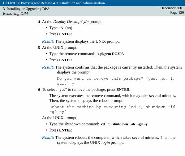
DEFINITY Proxy Agent Release 4.0 Installation and Administration
3 Installing or Upgrading DPARemoving DPA
December 2001Page 120
4 At the Display Desktop? y/n prompt,
• Type N (no)
• Press ENTER
Result: The system displays the UNIX prompt.
5 At the UNIX prompt,
• Type the remove command: # pkgrm DG3PA
• Press ENTER
Result: The system confirms that the package is currently installed. Then, the system displays the prompt:
Do you want to remove this package? [yes, no, ?, quit] y
6 To select “yes” to remove the package, press ENTER.
The system executes the remove command, which may take several minutes. Then, the system displays the reboot prompt:
Reboot the machine by executing ‘cd /; shutdown -i6 -g0 -y’
At the UNIX prompt,
• Type the shutdown command: cd /; shutdown -i6 -g0 -y
• Press ENTER
Result: The system reboots the computer, which takes several minutes. Then, the system displays the UNIX login prompt.

DEFINITY Proxy Agent Release 4.0 Installation and AdministrationDecember 2001
Page 1214 4Help Screens and Commands
IntroductionThe information in this chapter primarily targets new users who are unfamiliar with the Proxy Agent software.
The Proxy Agent application contains two types of help windows that users can access from any menu or application screen. The commands to access the help windows include the following:
• The list command (Ctrl-L) displays a Functions window that contains the available commands for the current Proxy Agent menu or application screen.
• The help command (Ctrl-Y) displays a help window for the current Proxy Agent menu or individual field on an application screen. Help windows can be lists of valid options for a specific field or instructions that explain the type of information to input in a field.
Note: Users need only type enough of each command to make it unique. For example: at the proxy main menu, instead of typing “proxy-admin”, you can type just “p”.
The Format Conventions section contains a table that describes the conventions used in this guide.

DEFINITY Proxy Agent Release 4.0 Installation and Administration
4 Help Screens and CommandsFunctions Window
December 2001Page 122
Functions WindowThe figure below is an example of a Functions window with associated hotkeys.
Users can access the Functions window (Ctrl-L) from any menu or application screen in the Proxy Agent.
Most commands have hotkeys, which are keyboard short cuts. Hotkeys allow users to execute a command without accessing the Functions window.
Figure 11. Functions window
Functions
sdnmlist LJK 040898
ctrl-xctrl-kfctrl-yctrl-ggctrl-dctrl-pctrl-n
ctrl-u
ctrl-e
CancelClear FieldHelpOnline GuidePage DownPage LeftPage RightPage SelectPage UpRefreshSubmit

DEFINITY Proxy Agent Release 4.0 Installation and Administration
4 Help Screens and CommandsCommands and Hotkeys
December 2001Page 123
Commands and HotkeysThe table below contains the description for the commands and the hotkeys that are available on the Proxy Agent.
Table 10. Commands and Hotkeys
Command Description
List command
Ctrl-L
Displays the Functions window that contains all of the available commands and associated hotkeys for the current screen.
To select an option from the Functions window,
• Press Ctrl-L to display the Functions window:
• Use the arrow keys or the TAB key to move the cursor to an option on the screen.
• Press ENTER to execute the command.
(1 of 4)

DEFINITY Proxy Agent Release 4.0 Installation and Administration
4 Help Screens and CommandsCommands and Hotkeys
December 2001Page 124
Help
Ctrl-Y
Displays a help window for a field or a menu, as described below:
• Field help window contains a list of options for the field.
• Main Menu help window contains explanations of the applications on the menu.
• Submenu help window contains available commands.
To access a help list for a specific field,
• Move the cursor to the field
• Press Ctrl-Y to display the help window
• Move the cursor to an option on the list
• Press ENTER to execute the option
To exit a help window without selecting an option, press ESC.
Submit
Ctrl-E
Saves changes made in the fields on an application screen and exits the screen.
Cancel
Ctrl-X
Exits a screen without saving changes.
Clear Field
Ctrl-K F
Deletes the data in the field where the cursor is located.
Users can also delete data in a field by pressing the SPACE BAR.
Table 10. Commands and Hotkeys
Command Description
(2 of 4)

DEFINITY Proxy Agent Release 4.0 Installation and Administration
4 Help Screens and CommandsCommands and Hotkeys
December 2001Page 125
Online Guide
Ctrl-G G
Displays a message with directions to access the Proxy Agent Installation Guide and User Guide from the Documentation folder on the UnixWare Desktop.
The Online Guide has been removed from the Proxy Agent.
Page Down
Ctrl-D
Displays the next numbered page in a multiple-page application.
Example: The MANAGED NODES application contains 10 pages. Press Ctrl-D to page down to the next page (2, 3, 4, etc.).
Page Up
Ctrl-U
Displays the previous numbered page in a multiple-page application.
Example: In the MANAGED NODES application, press Ctrl-U to page up to the previous page (4, 3, 2, 1).
Page Right
Ctrl-N
Displays the next subpage that is to the right of the current page.
Example: The MANAGED NODES application is similar to a spreadsheet with columns and rows on 5 subpages (a through e) for each numbered page.
Press Ctrl-N to access the next subpage (b, c, d, e) within a spreadsheet application.
Table 10. Commands and Hotkeys
Command Description
(3 of 4)

DEFINITY Proxy Agent Release 4.0 Installation and Administration
4 Help Screens and CommandsCommands and Hotkeys
December 2001Page 126
Page Left
Ctrl-P
Displays the previous subpage that is to the left of the current page.
Press Ctrl-P to access the previous subpage (d, c, b, a) within a spreadsheet application.
Page Select
(no hotkey)
Displays a window that contains all available page options within a multiple-page application.
The options may include any or all of the page commands listed above.
Refresh
(no hotkey)
Updates the screen with the current information.
Table 10. Commands and Hotkeys
Command Description
(4 of 4)

DEFINITY Proxy Agent Release 4.0 Installation and Administration
4 Help Screens and CommandsFormat Conventions
December 2001Page 127
Format ConventionsThe format conventions used in the Proxy Agent User Documentation are visual cues to help users identify the type of actions they should execute in the procedures.
UNIX systems have very specific rules for entering data at the UNIX prompt. The procedures in the guides show the text to be entered in 9 point bold font.
Users should type the text exactly as shown in the step. The steps include the conventions below:
• UPPER and lower case, symbols (periods, slashes, hyphens, underscores, etc.), and spaces within the command or path.
• If a command line wraps to the next line, this indicates that users should press the SPACE BAR before they type the data on the next line.
• If a web address (URL) wraps to the next line, do NOT insert a space.
• The procedures in the guides contain some data that are enclosed in brackets [password]. The brackets indicate that users should type the requested data without the brackets.
! CAUTION:Always check the typed data before pressing the ENTER or RETURN key. Notice the difference between the capital letter “O” and the number zero “0”. The only error message the UNIX system may display is: not found.
The format conventions described in the table below appear in the procedures and in the Result paragraph that follow most steps.

DEFINITY Proxy Agent Release 4.0 Installation and Administration
4 Help Screens and CommandsFormat Conventions
December 2001Page 128
Table 11. Format Conventions
Convention Description
Bold text Indicates that users should type the bold text exactly as shown. Example: Type display status
[Bold text in brackets]
Indicates that users should type data that is specific to their system, without the brackets.
Text enclosed within brackets contain either the data that may be different on your system or instructions to enter specific data for your system:
• Drive name [d:] which may be different on each system. Example: Type [d:] install
• System data from the PA001 form. Example: Type the [IP address] as shown on the PA001 form
• Options from a Help list. Example: Select the [managed node name] from the Help list
• Description of requested data. Example: Type the [device name] in the field as shown on the PA001 form: /dev/ttyxxx
(1 of 3)

DEFINITY Proxy Agent Release 4.0 Installation and Administration
4 Help Screens and CommandsFormat Conventions
December 2001Page 129
Result paragraph Describes the result of an action taken in a step, as described in the following example:
Result: The system displays the MAIN MENU.
A Result paragraph may also contain a message or a prompt that is displayed in the constant width font.
A prompt sets up the action to be taken in the next step.
Result: The system displays the command window that contains the prompt: Do you wish to continue? y/n
Series of Menu Options
File > Save
The greater than (>) symbol indicates that users should select an option from a series of menus.
For example, Click File > Save means that users should:
• Click on the option on the menu bar (File).
• Then click on the second option (Save) from the drop-down menu.
The term select is used in place of click if:
• A program does not accept mouse commands or
• Users need to choose an option from a Help list.
Table 11. Format Conventions
Convention Description
(2 of 3)

DEFINITY Proxy Agent Release 4.0 Installation and Administration
4 Help Screens and CommandsFormat Conventions
December 2001Page 130
Execution keys Appear in bold capital letters and indicate that users should press that key on the keyboard to execute a specific action.
Examples: Press ENTER (also refers to the RETURN key)
Combination keys
Ctrl-L
Ctrl-K F
The hyphen (-) between a function key (Ctrl, Alt, Shift) and a letter indicates that users should execute the actions described in the examples below:
Example: Press Ctrl-L (list command)
• Press and hold the Ctrl (Control) key
• Press the letter (L) key
• Then release both keys
Example: Press Ctrl-K F (clear field command)
• Press and hold the Ctrl (Control) key
• Press the first letter (K) key
• Release both keys
• Then press the second letter (F) key
Repeated keys Indicates that users should press the same key twice.
Example: Press ESC (closes a Help window)
Table 11. Format Conventions
Convention Description
(3 of 3)

DEFINITY Proxy Agent Release 4.0 Installation and AdministrationDecember 2001
Page 1315 5Access Procedures
IntroductionThis chapter contains screen descriptions and procedures to log in to the Proxy Agent from the UnixWare Desktop and UNIX prompt and procedures to access the various Proxy Agent menus and application screens.
This chapter also contains the procedures to:
• "Start the Proxy Agent" on page 149
• "Display of the Status Screen" on page 150
• "Stop the Proxy Agent" on page 156
The information in this chapter primarily targets new users who are unfamiliar with the Proxy Agent software.

DEFINITY Proxy Agent Release 4.0 Installation and Administration
5 Access ProceduresLog in to the Proxy Agent
December 2001Page 132
Log in to the Proxy AgentUsers can log in to the Proxy Agent from either the UNIX or the UnixWare Desktop. This section contains both procedures.
Users must use the Desktop procedures to access the Proxy Agent User Documentation. Refer to "Access the User Documentation" on page 139.
Log in from the UNIX ShellWhen logging from the UNIX shell, users can access all applications from the Proxy Agent MAIN MENU, except the Proxy Agent User Documentation.
Procedure Complete the following procedure to log in to the Proxy Agent MAIN MENU from the UNIX shell.
1 At the UNIX login prompt,
• Type the [g3maadm login]
• Press ENTER
Result: The system displays the Password prompt.
2 At the Password prompt,
• Type the g3maadm [password]
• Press ENTER
Result: The system displays the prompt: Display Desktop? y/n

DEFINITY Proxy Agent Release 4.0 Installation and Administration
5 Access ProceduresLog in from the UNIX Shell
December 2001Page 133
3 At the prompt,
• Type N (no)
• Press ENTER
Result: The system displays the UNIX prompt.
4 At the UNIX prompt,
• Type proxy
• Press ENTER
Result: The system displays the Proxy Agent MAIN MENU.
MAIN MENU
Please select one of the following Proxy Agent applications:
To access documentation, type ’online-guide’. To exit Proxy Agent, type ’exit’.Throughout Proxy Agent, to select functions, press Ctrl-L.
enter application name:>
communicationconfigurationemulation
exitonline-guide
proxy-adminunix-shell
sdnmmain LJK 040798
(PROXY AGENT)

DEFINITY Proxy Agent Release 4.0 Installation and Administration
5 Access ProceduresLog in from the Desktop
December 2001Page 134
5 At the command line, enter an application name. For example:
• Type proxy-admin
• Press ENTER
Result: The system displays the selected application screen.
Log in from the Desktop When logging in to the UnixWare Desktop, the system displays the following two screens before it displays the Proxy Agent MAIN MENU:
• The UnixWare Desktop contains the DEFINITY_Proxy icon that opens the DEFINITY_Proxy folder.
• The DEFINITY_Proxy folder contains the following executable icons or folders:
– Proxy_Agent icon opens the MAIN MENU that lists the commands to access the Proxy Agent applications.
– Documentation icon opens a PDF menu to access the Proxy Agent User Documentation and PA001 forms.
– IO_Setup folder contains the icons to access the Dialers file and the Devices file. Users need root password to edit these files.
Note: The examples in this section show typical UnixWare Desktop screens. Your desktop may look somewhat different depending on the configuration of your system.
Users execute most of the daily operation tasks in the PROXY ADMIN menu. Chapters 4 through 8 contain field definitions and procedures to execute various tasks on the administration screens.

DEFINITY Proxy Agent Release 4.0 Installation and Administration
5 Access ProceduresLog in from the Desktop
December 2001Page 135
Procedure Complete the following procedure to log in to the UnixWare Desktop and access the Proxy Agent MAIN MENU.
Note: Accessing the UnixWare Desktop can only be done from the Proxy Agent Console.
1 At the UNIX login prompt,
• Type the [g3maadm login]
• Press ENTER
Result: The system displays the Password prompt.
2 At the Password prompt,
• Type your [password]
• Press ENTER
Result: The system displays the prompt: Display Desktop? y/n
3 At the prompt,
• Type Y (yes)
• Press ENTER
Result: The system displays the UnixWare Desktop.

DEFINITY Proxy Agent Release 4.0 Installation and Administration
5 Access ProceduresLog in from the Desktop
December 2001Page 136
4 Double-click the DEFINITY_Proxy icon to open the folder.
Result: The system displays the contents of the DEFINITY_Proxy folder.
UnixWare Desktop - g3maadm
D E F IN IT Y _P roxy
F o ld e r_M a p
A d m in _ To o ls
M ailb o x
A p p lica tio n s
P re fe re n ce s
D is ks_ e tc
H e lp _ D e s k
G a m es
S hu tdo w n
F ile E d it V iew G o To H e lp
s d n m d top K L C 0 3

DEFINITY Proxy Agent Release 4.0 Installation and Administration
5 Access ProceduresLog in from the Desktop
December 2001Page 137
5 Double-click the Proxy_Agent icon to access the Proxy Agent MAIN MENU.
Result: The system displays the Proxy Agent MAIN MENU.
Folder: DEFINITY_Proxy
Proxy_AgentDocumentationIO_Setup
sdnmprox LJK 092299
File Edit View Go To Help

DEFINITY Proxy Agent Release 4.0 Installation and Administration
5 Access ProceduresLog in from the Desktop
December 2001Page 138
6 At the command line, enter an application name. For example:
• Type proxy-admin
• Press ENTER
Result: The system displays the selected application screen.
MAIN MENU
Please select one of the following Proxy Agent applications:
To access documentation, type ’online-guide’. To exit Proxy Agent, type ’exit’.Throughout Proxy Agent, to select functions, press Ctrl-L.
enter application name:>
communicationconfigurationemulation
exitonline-guide
proxy-adminunix-shell
sdnmmain LJK 040798
(PROXY AGENT)

DEFINITY Proxy Agent Release 4.0 Installation and Administration
5 Access ProceduresAccess the User Documentation
December 2001Page 139
Access the User Documentation In this release, the Proxy Agent User Documentation for Installation and Administration is delivered on the product CD-ROM entitled: DEFINITY Network Management Proxy Agent Release 4.0.
During the installation of the Proxy Agent, the installation script copies the User Documentation and PA001 forms to the avayadoc directory. Users can only access the User Documentation from the UnixWare Desktop.
Users also have the option of printing the guides directly from the DEFINITY Network Management Proxy Agent CD-ROM.
PDF viewer The Proxy Agent User Documentation are PDF files. Users can access any chapter in the book by using the built-in links in the table of contents, index, and chapters. Users can also use the search feature to find specific information.
The PDF viewer is public domain software. Users can learn more about the PDF viewer from the UNIX manual page entitled: XPDF. To access the manual page, enter the man xpdf command at a UNIX prompt.
Online_guide command
The Proxy Agent User Documentation replaces the Online Guide. The online_guide command is still visible on the Proxy Agent MAIN MENU and Functions screen.
If users execute the command, the system displays a window with instructions for viewing the documentation on the UnixWare Desktop.
Procedure Complete the following procedure to access the Proxy Agent Installation Guide and the User Guide from the Documentation folder on the Desktop.

DEFINITY Proxy Agent Release 4.0 Installation and Administration
5 Access ProceduresAccess the User Documentation
December 2001Page 140
1 Log in as g3maadm and access the UnixWare Desktop.
Result: The system displays the Desktop.
2 Click the DEFINITY_Proxy icon.
Result: The system displays the DEFINITY_Proxy folder.
3 Click the Documentation icon.
Result: The system displays the main menu for the PDF viewer.
4 Select an option from the main menu to access the documentation.
5 To exit the PDF viewer from the Menu Bar, select File > Exit.The system displays the DEFINITY_Proxy folder.
Folder: DEFINITY_Proxy
Proxy_AgentDocumentationIO_Setup
sdnmprox LJK 092299
File Edit View Go To Help

DEFINITY Proxy Agent Release 4.0 Installation and Administration
5 Access ProceduresReview of the Main Menu
December 2001Page 141
Review of the Main Menu The Proxy Agent MAIN MENU contains the commands to access the Proxy Agent application screens, as show in the following figure.
Figure 12. Proxy Agent MAIN MENU
The following table contains the descriptions of the commands on the Proxy Agent MAIN MENU.
MAIN MENU
Please select one of the following Proxy Agent applications:
To access documentation, type ’online-guide’. To exit Proxy Agent, type ’exit’.Throughout Proxy Agent, to select functions, press Ctrl-L.
enter application name:>
communicationconfigurationemulation
exitonline-guide
proxy-adminunix-shell
sdnmmain LJK 040798
(PROXY AGENT)

DEFINITY Proxy Agent Release 4.0 Installation and Administration
5 Access ProceduresReview of the Main Menu
December 2001Page 142
Table 12. Proxy Agent MAIN MENU
Command Description
communication Accesses the Communication application and displays the COMMUNICATION MANAGER screen. Users can manually connect and disconnect a Proxy Agent to and from managed nodes for real-time administration.
Refer to Chapter 12, "Communication Application"
emulation Accesses the Emulation application. The Emulation screen provides direct communication with a managed node for real-time administration.
Refer to Chapter 13, "Emulation Application"
configuration Accesses the Configuration application. This application contains two commands to edit either of the configuration screens:
• change hardware to edit the CHANGE HARDWARE screen
• change user-interface to edit of the CHANGE USER_INTERFACE screens (4 pages)
Refer to Chapter 14, "Configuration Application"
(1 of 3)

DEFINITY Proxy Agent Release 4.0 Installation and Administration
5 Access ProceduresReview of the Main Menu
December 2001Page 143
proxy-admin Accesses the PROXY ADMIN menu. This menu contains the following commands:
• The change and display commands allow users to administer or view the application following screens:
– Alarm Devices
– Filter Set
– Default Location
– Managed Nodes
– Network Managers
– Default Login
• The add and remove commands allow users to access the FILTER SET screen and create or delete filter sets
• The start and stop commands allow users to turn on or turn off the Proxy Agent
• The quit command allows users to exit the PROXY ADMIN menu
• The status command allows users to view the STATUS screen. The STATUS screen is for display only.
Refer to "Review of the Proxy Admin Menu" on page 145
Table 12. Proxy Agent MAIN MENU
Command Description
(2 of 3)

DEFINITY Proxy Agent Release 4.0 Installation and Administration
5 Access ProceduresReview of the Main Menu
December 2001Page 144
exit Closes the Proxy Agent MAIN MENU.
online-guide Displays a window with instructions to access the UnixWare Desktop in order to view the Proxy Agent Installation Guide and the User Guide.
The Online Guide has been removed from the Proxy Agent.
Refer to "Access the User Documentation" on page 139
unix-shell Accesses the UNIX prompt.
Table 12. Proxy Agent MAIN MENU
Command Description
(3 of 3)

DEFINITY Proxy Agent Release 4.0 Installation and Administration
5 Access ProceduresReview of the Proxy Admin Menu
December 2001Page 145
Review of the Proxy Admin MenuThe PROXY ADMIN menu contains the commands to access the Proxy Agent administration screens and to start and stop the Proxy Agent. The following figure shows the commands on the PROXY ADMIN screen. .
Figure 13. PROXY ADMIN screen
Please select from the following:
Enter 'quit' to exit the program
enter command:>
addchangedisplay
removestart
stopquit
(PROXY ADMIN)

DEFINITY Proxy Agent Release 4.0 Installation and Administration
5 Access ProceduresReview of the Proxy Admin Menu
December 2001Page 146
Command descriptions
The following table describes the commands on the PROXY ADMIN screen. Users must have a g3maadm login to execute the commands and administer the Proxy Agent.
Table 13. PROXY ADMIN screen
Command Description
add Accesses the FILTER SET screen in the “add” mode. Users create the alarm filtering criteria for a new filter set with this command.
Note: Users must STOP the Proxy Agent before executing the add command.
Refer to Chapter 9, "Filter Set Administration".
remove Accesses the FILTER SET screen in the “remove” mode. Users can delete existing alarm filters with this command.
Note: Users must STOP the Proxy Agent before executing the remove command.
The Proxy Agent executes one of the following options:
• Deletes the filter set if it is not assigned to any managed node
• Replaces the filter set with the default filter if the filter is assigned to managed nodes
Refer to Chapter 9, "Filter Set Administration".
(1 of 3)

DEFINITY Proxy Agent Release 4.0 Installation and Administration
5 Access ProceduresReview of the Proxy Admin Menu
December 2001Page 147
change Accesses the administration following screens. The change command allows users to edit the selected screen.
Note: Users must STOP the Proxy Agent before executing the change command.
• change network-managersRefer to Chapter 6, "Review the Network Managers Screen"
• change default-locationRefer to Chapter 7, "Review of the Default Location Screen"
• change alarm-devicesRefer to Chapter 8, "Review of the ALARM DEVICES Screen"
• change filter-setRefer to Chapter 9, "Review of the Filter Set Screen"
• change managed-nodesRefer to Chapter 11, "Review of the Managed Nodes Screen"
• change default loginRefer to Chapter 10, "Review of the Default Login Screen"
Table 13. PROXY ADMIN screen
Command Description
(2 of 3)

DEFINITY Proxy Agent Release 4.0 Installation and Administration
5 Access ProceduresReview of the Proxy Admin Menu
December 2001Page 148
display Shows the administration screens and the STATUS screen in the view-only mode. The display command does not allow users to change the screens.
Note: Users do not have to STOP the Proxy Agent before executing the display command.
• display alarm-devices
• display filter-set
• display default-location
• display default-login
• display managed-nodes
• display status -- Refer to "Display the Status Screen" on page 155
start Initiates a Proxy Agent connection to the managed nodes.
Refer to "Start the Proxy Agent" on page 149
stop Drops the Proxy Agent connection to the managed nodes.
Refer to "Stop the Proxy Agent" on page 156
quit Closes the PROXY ADMIN screen and displays the Proxy Agent MAIN MENU.
Table 13. PROXY ADMIN screen
Command Description
(3 of 3)

DEFINITY Proxy Agent Release 4.0 Installation and Administration
5 Access ProceduresStart the Proxy Agent
December 2001Page 149
Start the Proxy Agent The PROXY ADMIN screen contains the command to start the Proxy Agent System connection to the administered managed nodes.
Each time users start the Proxy Agent, they should also display the STATUS screen to verify that the Proxy Agent is active.
Procedure Complete the following procedure to start the Proxy Agent connection.
1 Access the PROXY ADMIN screen. In the command line,
• Type start proxy-agent
• Press ENTER
Result: The system displays the command window that contains the prompt: Do you wish to continue? Yes No
2 To select Yes, press ENTER.
Result: The system starts the Proxy Agent. Then, the system displays the PROXY ADMIN screen with the confirmation message:
Command completed successfully.

DEFINITY Proxy Agent Release 4.0 Installation and Administration
5 Access ProceduresDisplay of the Status Screen
December 2001Page 150
Display of the Status ScreenThe STATUS screen is a view-only screen that contains the following information:
• Proxy Agent state and connection type
• Alarm forwarding state
• Node name and state
• Connection statistics only for the ECS, G3, MCU, IP600, and DEFINITY One managed nodes
• Status of the Proxy Agent
The STATUS screen does not display any connection statistics for the following managed nodes:
• DEFINITY AUDIX
• Intuity AUDIX
• Intuity Interchange
• Call Management System (CMS)
• CONVERSANT
The Proxy Agent only supports alarm handling for these products.

DEFINITY Proxy Agent Release 4.0 Installation and Administration
5 Access ProceduresDisplay of the Status Screen
December 2001Page 151
Figure The following figure shows an example of a STATUS screen (view-only).
Figure 14. STATUS screen
STATUS
Node NameCon Type
ecs1static
g3dynamic
StateTimeout
up
idle60
Last ConnectionLast Used
12/01/99 14:37:4812/01/99 15:08:51
AttemptsConnects
11
00
Proxy Agent State: active Alarm Forwarding: ok
RequestsResponses
8585
00
ErrorsCounters Reset
0
012/05/99 11:03:55
sdnmdst LJK 092299
(PROXY ADMIN) Page 1display status
Command successfully completed, select Cancel to return to the menu

DEFINITY Proxy Agent Release 4.0 Installation and Administration
5 Access ProceduresReview of the Status Screen Fields
December 2001Page 152
Review of the Status Screen FieldsThe following table contains the description for each column on the STATUS screen.
Several of the columns contain two types of data in the column.
Table 14. STATUS screen
Column Description
Proxy Agent State Identifies the current activity status of the Proxy Agent:
active -- The Proxy Agent has been started
not active -- The Proxy Agent has been stopped
Alarm Forwarding Identifies the current state of the alarm forwarding feature.
The alarm forwarding feature is active only if the user has administered the ALARM DEVICES screen. Users can turn-off alarm forwarding for individual managed nodes from the MANAGED NODES screen.
The states include:
ok -- Alarm forwarding is active and functioning
failed -- Alarm forwarding is active, but is not functioning
other -- Identifies one of the following conditions:
• Proxy Agent is not active
• Alarm forwarding feature is not turned on
(1 of 3)

DEFINITY Proxy Agent Release 4.0 Installation and Administration
5 Access ProceduresReview of the Status Screen Fields
December 2001Page 153
Node Name Identifies the name of the managed node that is associated with the Proxy Agent.
Con Type Identifies the type of Proxy Agent connection that users administer for ECS, G3, MCU, IP600, and DEFINITY One systems. A connection can be one of the following types:
• static (continuous connection)
• dynamic (temporary connection on an as-needed basis)
State The State field identifies the current status of the Proxy Agent connection to a managed node. The states include:
init (initiate) -- A connection attempt is in progress
up -- The connection is established
down -- The connection attempt has failed
off -- The connection has been turned off
idle -- A dynamic connection is not connected in standby mode
other -- The connection has failed and the state is unknown
Timeout Contains the number of minutes a dynamic connection will remain up without receiving data transmission.
Table 14. STATUS screen
Column Description
(2 of 3)

DEFINITY Proxy Agent Release 4.0 Installation and Administration
5 Access ProceduresReview of the Status Screen Fields
December 2001Page 154
Last Connection The date and time of the last successful connection.
Last Used The date and time of the last successful data retrieval.
Attempts The number of connection attempts since the counter was reset to zero.
Connects The number of successful connections since the counter was reset to zero.
Data Requests The number of requests for data since the counter was reset to zero.
Data Responses The number of successful responses to data requests since the counter was reset to zero.
Errors The number of errors that occurred during data requests since the counter was reset to zero.
Counters Reset The date and time the counter was reset to zero.
Table 14. STATUS screen
Column Description
(3 of 3)

DEFINITY Proxy Agent Release 4.0 Installation and Administration
5 Access ProceduresDisplay the Status Screen
December 2001Page 155
Display the Status Screen Users should display the STATUS screen each time they start the Proxy Agent so that they can review the following information:
• Verify that the Proxy Agent connection is active
• View the status of the Alarm Forwarding feature
• View the connection statistics for the G3, ECS, and MCU managed nodes
Procedure Complete the following procedure to display the STATUS screen.
1 Access the PROXY ADMIN menu. In the command line,
• Type display status
• Press ENTER
Result: The system displays the STATUS screen.
2 Check the STATUS screen to verify the current state of the Proxy Agent connections and statistics.
3 Press Ctrl-X to exit the screen.
Result: The system closes the STATUS screen and displays the PROXY ADMIN screen.

DEFINITY Proxy Agent Release 4.0 Installation and Administration
5 Access ProceduresStop the Proxy Agent
December 2001Page 156
Stop the Proxy Agent The PROXY ADMIN screen contains the command to stop a Proxy Agent connection to the administered managed nodes.
Users must stop the Proxy Agent before they can enter a change command to edit an administration screen.
! CAUTION:When you stop the Proxy Agent, the nodes connected to the Proxy Agent are dropped.
Users do not have to stop the Proxy Agent entering a display command. Users can view an administration screen while the Proxy Agent is running.
Complete the following procedures to stop the Proxy Agent connection.
1 Access the PROXY ADMIN screen. In the command line,
• Type stop proxy-agent
• Press ENTER
Result: The system displays the command window that contains the prompt: Do you wish to continue? Yes No
2 To select Yes, press ENTER.
Result: The system stops the Proxy Agent. Then, displays the PROXY ADMIN screen with the confirmation message: Command completed successfully.

DEFINITY Proxy Agent Release 4.0 Installation and AdministrationDecember 2001
Page 1576 6Network Managers Administration
IntroductionThe NETWORK MANAGERS screen provides the Network Management System (NMS) with access to the SNMP data collected from the managed nodes. The NMS applications use the SNMP data to populate the tables and graphical displays in the appropriate DEFINITY Network Management (DNM) screens.
The purpose of the NETWORK MANAGERS screen is to administer the communication link between the Proxy Agent and the Network Management System (NMS).
see also:
– Management Information Base (MIB) Chapter 1, "Management Information Base (MIB)"
– Cache Mechanism Chapter 1, "Cache mechanism"
– SNMP Traps Chapter 1, "SNMP Access"
The sections below describe interactions between the network managers and the Proxy Agent.

DEFINITY Proxy Agent Release 4.0 Installation and Administration
6 Network Managers AdministrationReview the Network Managers Screen
December 2001Page 158
Review the Network Managers Screen The figure below shows the fields on the NETWORK MANAGERS screen.
Figure 15. Network Managers screen

DEFINITY Proxy Agent Release 4.0 Installation and Administration
6 Network Managers AdministrationReview the Network Managers Screen
December 2001Page 159
The table below contains the field descriptions for the NETWORK MANAGERS screen.
Table 15. Network Managers Screen
Field Description
Get Community String Identifies the Proxy Agent’s SNMP Get Community String. The NMS network manager uses the get community string to validate SNMP get requests.
Valid options for this field are:
• public (default)
• Any name that identifies a private network
! CAUTION:Users must administer the name of the get community string (public or private) in the comparable fields on the NMS screens. The name must match on both systems, otherwise the get request will fail.
Required field.
Field size: 15 characters
(1 of 4)

DEFINITY Proxy Agent Release 4.0 Installation and Administration
6 Network Managers AdministrationReview the Network Managers Screen
December 2001Page 160
Set Community String Identifies the Proxy Agent’s Get Community String. The NMS network manager uses the set community string to validate SNMP set requests.
The default for this field is: g3pa
! CAUTION:Users must administer the g3pa as the name of the set community string in the comparable fields on the NMS screens. The name must match on both systems, otherwise the set request will fail.
Required field.
Field size: 15 characters
Table 15. Network Managers Screen
Field Description
(2 of 4)
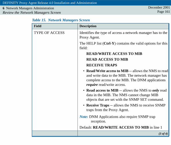
DEFINITY Proxy Agent Release 4.0 Installation and Administration
6 Network Managers AdministrationReview the Network Managers Screen
December 2001Page 161
TYPE OF ACCESS Identifies the type of access a network manager has to the Proxy Agent.
The HELP list (Ctrl-Y) contains the valid options for this field:
READ/WRITE ACCESS TO MIB
READ ACCESS TO MIB
RECEIVE TRAPS
• Read/Write access to MIB -- allows the NMS to read and write data to the MIB. The network manager has complete access to the MIB. The DNM applications require read/write access.
• Read access to MIB -- allows the NMS to only read data in the MIB. The NMS cannot change MIB objects that are set with the SNMP SET command.
• Receive Traps -- allows the NMS to receive SNMP traps from the Proxy Agent.
Note: DNM Applications also require SNMP trap reception.
Default: READ/WRITE ACCESS TO MIB in line 1
Table 15. Network Managers Screen
Field Description
(3 of 4)

DEFINITY Proxy Agent Release 4.0 Installation and Administration
6 Network Managers AdministrationReview the Network Managers Screen
December 2001Page 162
IP ADDRESS Identifies the Internet Protocol (IP) address of the NMS network manager.
The valid options for this field:
• Asterisk (*) -- default in line 1. The asterisk allows access to all NMS network managers. The asterisk is not valid for RECEIVE TRAPS access.
or
• IP address of the NMS in dot format.
Example: 126.1.205.86
! SECURITY ALERT:Users should enter the IP address for each network manager to limit access to the MIB.
Required field.
Field size: 15 characters
Table 15. Network Managers Screen
Field Description
(4 of 4)

DEFINITY Proxy Agent Release 4.0 Installation and Administration
6 Network Managers AdministrationAdminister the Network Managers
December 2001Page 163
Administer the Network Managers The NETWORK MANAGERS screen contains the fields to administer the communication link between the Proxy Agent and Network Management System (NMS).
Users administer each NMS as a network manager and assign the type of access each network manager has to the Proxy Agent Management Information Base (MIB)
Required access Users must administer three types of access for each network manager:
• Read/Write Access to MIB
• Read only Access to MIB
• Receive Traps
Users assign each type of access on a separate line in the NETWORK MANAGERS screen.
PA001 form The data that users enter in the fields on the NETWORK MANAGERS screen must match the data on the PA001 form in the Proxy Agent section.

DEFINITY Proxy Agent Release 4.0 Installation and Administration
6 Network Managers AdministrationAdminister the Network Managers
December 2001Page 164
Procedure Complete the procedure below to add new network managers or to change data for existing network managers.
1 At the Proxy Agent MAIN MENU,
• Type proxy-admin
• Press ENTER
Result: The system displays the PROXY ADMIN menu.
2 In the command line,
• Type change network-managers
• Press ENTER
Result: The system displays the NETWORK MANAGERS screen.
3 Compare the data on the PA001 form to the fields on the NETWORK MANAGERS screen:
Get Community String: public
Set Community String: g3pa
If the data does not match, then change the fields to match the data on the PA001 form.

DEFINITY Proxy Agent Release 4.0 Installation and Administration
6 Network Managers AdministrationAdminister the Network Managers
December 2001Page 165
4 For each network manager, complete the fields below to add the READ/WRITE ACCESS TO MIB permission:
• In the TYPE OF ACCESS column, move the cursor to a blank line number.
– Press Ctrl-Y to display the Help list
– Select READ/WRITE ACCESS TO MIB– Press ENTER to display the selection in the field
• In the IP ADDRESS column, type the [IP address] in the field for the same line number. Example of an IP Address in the dot format: 126.1.205.86
5 For each network manager, complete the fields below to add the RECEIVE TRAPS permission. The IP address should match the address in step 4 for each network manager.
• In the TYPE OF ACCESS column, move the cursor to a blank line number.
– Press Ctrl-Y to display the Help list
– Select RECEIVE TRAPS
– Press ENTER to display the selection in the field
• In the IP ADDRESS column, type the [IP address] in the field for the same line number.
6 Repeat steps 4 and 5 to administer each network manager.
7 Press Ctrl-E to submit the changes.
Result: The system save the data and displays the PROXY ADMIN menu.
8 New Installations. Complete the procedure to "Administer the Default Location" on page 174.

DEFINITY Proxy Agent Release 4.0 Installation and AdministrationDecember 2001
Page 1667 7Default Location Administration
IntroductionUse the DEFAULT LOCATION screen to administer the system-wide default location submaps for supported systems. Users can override the default location map for individual managed nodes from the MANAGED NODES screen on the Proxy Agent and from the NMS network server.
The DEFAULT LOCATION screen allows users to designate the type of submap that shows the location of managed nodes and their associated Proxy Agents.
The Network Management System (NMS) displays the submaps in a graphical format with icons that represent the managed nodes and the Proxy Agent. Users can easily monitor the health and status of all the managed nodes from the submaps.
Users can organize the managed nodes by location or by custom categories.
The examples below offer some suggestions for organizing the managed nodes:
• Generic submap -- Select the generic submap to view all the managed nodes and Proxy Agents on one submap. The generic submap is the system default.
• USA submap -- Select the USA submap to show the location of managed nodes in the lower 48 states and in Alaska and Hawaii. The associated State submap shows the Proxy Agent icon with connecting lines to the managed nodes icons that are located in that state.

DEFINITY Proxy Agent Release 4.0 Installation and Administration
7 Default Location AdministrationIntroduction
December 2001Page 167
• Custom submap -- Select the custom submap to organize the managed nodes by categories, such as private networks, regions, functions, or international locations. Use the associated Submap Name to identify groups or locations within the categorizes, such as:
– Private Network may consist of the Lab and Testing groups
– Regions may consist of North, East, South, and West groups
– Functions may consist of Telemarketing, Sales, and Customer Service groups
– International locations may consist of Africa, Spain, Greece groups
Users can organize the managed nodes by selecting one type of submap or any combination of the three submaps.
Managed Nodes screen
Users can change the type of submap on the MANAGED NODES screen for individual managed nodes. The change overrides the submap selection on the DEFAULT LOCATION screen only for the individual managed node.
NMS submaps The submaps that display on the NMS network servers provide the current status of the managed nodes through the use of colored icons and different types of connecting lines.
The color of the managed node icons identifies the health status of the managed nodes. The icon color changes to indicate the highest severity level of any DNM exception that has occurred on the managed nodes.
The type of the connecting lines (broken or solid lines) between the Proxy Agent and managed nodes icons identify either a static or dynamic connection. The color of the line indicates the connection status of the Proxy Agent.

DEFINITY Proxy Agent Release 4.0 Installation and Administration
7 Default Location AdministrationReview of the Default Location Screen
December 2001Page 168
Review of the Default Location ScreenThe fields that display on the DEFAULT LOCATION screen depend on the type of submap that users select as the default location for new managed nodes.
The figures on the next pages show the fields that display on the DEFAULT LOCATION screen for the submaps listed below:
• Generic submap (default)
• USA submap
• Custom submap

DEFINITY Proxy Agent Release 4.0 Installation and Administration
7 Default Location AdministrationReview of the Default Location Screen
December 2001Page 169
Generic submap screen
The figure below shows the DEFAULT LOCATION screen for the generic submap. Only the Submap Type field displays for generic submaps.
Figure 16. Generic submap field
DEFAULT LOCATION
sdnmdefg LJK 040798
(PROXY ADMIN) page 1 of 1change default-location
* Submap Type:>generic

DEFINITY Proxy Agent Release 4.0 Installation and Administration
7 Default Location AdministrationReview of the Default Location Screen
December 2001Page 170
USA submap screen
The figure below shows the DEFAULT LOCATION screen for the USA submap with the following fields:
• Submap Type
• State (Alabama is the default state)
Figure 17. USA submap fields
DEFAULT LOCATION
sdnmdefu LJK 040798
(PROXY ADMIN) page 1 of 1change default-location
Submap Type:
* State:>A
usa
labama

DEFINITY Proxy Agent Release 4.0 Installation and Administration
7 Default Location AdministrationReview of the Default Location Screen
December 2001Page 171
Custom submap screen
The figure below shows the DEFAULT LOCATION screen for the custom map with the following fields:
• Submap Type
• Submap Name.
Figure 18. Custom submap fields
DEFAULT LOCATION(PROXY ADMIN) page 1 of 1change default-location
* Submap Type:
Submap Name:
>custom
Africa

DEFINITY Proxy Agent Release 4.0 Installation and Administration
7 Default Location AdministrationReview of the Default Location Screen
December 2001Page 172
Field descriptions The table below contains the field descriptions for the DEFAULT LOCATION screen.
Table 16. Default Location Screen
Field Description
Submap Type Identifies the type of submap.
The Help list (Ctrl-y) contains the valid options for this field:
generic (default)
usa
custom
The fields that display on the DEFAULT LOCATION screen will change depending on the type of submap:
• If users select usa, the system displays the State field
• If users select custom, the system displays the Submap Name field
Users can change the submap type for individual managed nodes on page C of the MANAGED NODES screen. The changes override the submap type selected on the DEFAULT LOCATION screen only for the individual managed node.
(1 of 2)

DEFINITY Proxy Agent Release 4.0 Installation and Administration
7 Default Location AdministrationReview of the Default Location Screen
December 2001Page 173
State If users select usa in the Submap Type field, the system displays the State field.
The Help list (ctrl-y) contains 50 states as valid options for this field.
Users select the appropriate state for the location of the managed nodes.
When users administer the managed nodes on the MANAGED NODES screen, they can change the state location for individual managed nodes.
System default: Alabama
Submap Name If users select custom in the Submap Type field, the system displays the Submap Name field.
Users can type a default name for the custom submaps.
When users administer the managed nodes on the MANAGED NODES screen, then they can change the submap name for individual managed nodes.
Default: Blank
Field size: 40 characters
Table 16. Default Location Screen
Field Description
(2 of 2)

DEFINITY Proxy Agent Release 4.0 Installation and Administration
7 Default Location AdministrationAdminister the Default Location
December 2001Page 174
Administer the Default LocationThis section contains the procedures to select a submap as the system default location for new managed nodes.
Note: To save time during the administration of many managed nodes with different locations, users can change the submap selection on the DEFAULT LOCATION before they administer managed nodes with the same on the MANAGED NODES screen.
Procedure Complete the procedure below to select the system default location for new managed nodes.
1 Access the PROXY ADMIN menu.
2 Stop the Proxy Agent, if running.
3 In the command line on the PROXY ADMIN menu,
• Type change default-location
• Press ENTER
Result: The system displays the DEFAULT LOCATION screen.

DEFINITY Proxy Agent Release 4.0 Installation and Administration
7 Default Location AdministrationAdminister the Default Location
December 2001Page 175
4 In the Submap Type field,
• Press Ctrl-Y to display the Help list
• Select a submap type from the list.
• Press ENTER.
• Then, go to the appropriate step for the selected submap:
generic (go to step 7)
usa (go to step 5)
custom (go to step 6)
5 USA submap type. In the State field select a state as the default location:
• Press Ctrl-Y to display the Help list
• Select a state from the list
• Press ENTER
• Go to step 7
6 Custom submap type. In the Submap Type field,
• Type a [custom name] for the default location
• Go to step 7
7 Press Ctrl-E to submit the changes.
Result: The system saves the changes and displays the PROXY ADMIN menu.
8 New Installation. Complete the procedure to "Administer the Alarm Device" on page 181.

DEFINITY Proxy Agent Release 4.0 Installation and AdministrationDecember 2001
Page 1768 8Alarm Device Administration
IntroductionUse the ALARM DEVICES screen to administer alarm devices that receive alarms from supported managed nodes or send the alarms to INADS. Also administer the supported systems as managed nodes on the MANAGED NODES screen. The MANAGED NODES screen also allows users to administer alarm forwarding on a node-by-node basis.
The ALARM DEVICES screen contains the fields to administer the alarm stream to enable the Proxy Agent to receive alarms from managed nodes and to forward alarms to the Initialization and Administration System (INADS).
In this release, the Proxy Agent only receives alarms from the managed nodes listed below:
• DEFINITY ECS, G3, MCU, IP600, and DEFINITY One systems
• DEFINITY AUDIX
• Intuity AUDIX
• Intuity Interchange
• Call Management System (CMS)
• CONVERSANT system
The Proxy Agent forwards the alarms received from the managed nodes to INADS, which is the default destination. Users can edit the alarm destination fields in order to forward the alarms to an alarm reception device that is supported by the current release of the Proxy Agent.
DEFINITY Proxy Agent Release 4.0 Installation and Administration
8 Alarm Device AdministrationIntroduction
December 2001Page 177
Alarm forwarding
The alarm forwarding feature is active only if at least one alarm sender is administered.
You can turn alarm forwarding on and off for individual managed nodes on page A of the MANAGED NODES screen.
See also To troubleshoot alarm problems, refer to "View Alarm and Error Logs" on page 321.

DEFINITY Proxy Agent Release 4.0 Installation and Administration
8 Alarm Device AdministrationReview of the ALARM DEVICES Screen
December 2001Page 178
Review of the ALARM DEVICES Screen Use the ALARM DEVICES screen to enter up to 15 alarm devices to receive alarms from managed nodes or to forward alarms to the Initialization and Administration System (INADS).
Figure 19. Alarm Devices screen

DEFINITY Proxy Agent Release 4.0 Installation and Administration
8 Alarm Device AdministrationReview of the ALARM DEVICES Screen
December 2001Page 179
Field descriptions The table below contains the descriptions of the fields on the ALARM DEVICES screen.
Table 17. Alarm Devices Screen
Field Description
DEVICE TYPE
receiversender
Identifies the device as a receiver or sender of alarms.
Default: Blank
Field size: 8 characters
BAUD RATE
12002400960019200IP
Specifies the baud rate for modem connections.
Enter IP for TCP/IP connections.
Default: Blank
Field size: 5 characters
DEVICE NAME
ttyxxxx
Specifies the tty device used to receive or send alarms. Required for serial alarm devices (baud rate field contains baud rate information).
Leave blank if baud rate field is “IP.“
Default: Blank
Field size: 8 characters
(1 of 2)

DEFINITY Proxy Agent Release 4.0 Installation and Administration
8 Alarm Device AdministrationReview of the ALARM DEVICES Screen
December 2001Page 180
PHONE NUMBER Specifies the phone number used to receive or send alarms.
Appears when the baud rate field contains baud rate information, and does not appear if the baud rate field is “IP.”
If the baud rate field is not IP, and the device type is receiver, the phone number deafult is the INADS phone number.
Default: blank
Field size: 20 characters
IP ADDRESS Contains the IP address used to send alarms over IP.
This field is turned on when the device type is “sender”
and the baud rate is “IP.”
Default: blank
Field size: 16 characters
PORT Contains the port number used to receive or send alarms over IP. The field is turned on when and the baud rate is “IP.”2.0.2
Default: blank
Field size: 5 characters
Table 17. Alarm Devices Screen
Field Description
(2 of 2)

DEFINITY Proxy Agent Release 4.0 Installation and Administration
8 Alarm Device AdministrationAdminister the Alarm Device
December 2001Page 181
Administer the Alarm Device The ALARM DEVICES screen enables the Proxy Agent to receive alarms from managed nodes and to forward alarms to INADS.
PA001 form Users should refer to the sections on the PA001 form to get the data that they must enter on the ALARM DEVICES screen:
• In the Devices section, refer to the Device Name fields for the TTY ports that Receive Alarms and Send (forward) Alarms.
• In the Proxy Agent section, refer to Alarm Device table for phone numbers of the devices for the alarm source and alarm destination.
The default for the destination phone number is the INADS phone number. Users can enter a different phone number in the field.
Procedure Complete the procedure below to administer the ALARM DEVICES screen to receive and forward alarms.
1 Access the PROXY ADMIN menu.
2 Stop the Proxy Agent, if running.
3 In the command line on the PROXY ADMIN menu,
• Type change alarm-device
• Press ENTER
Result: The system displays the ALARM DEVICES screen.
Refer to the PA001 form for the information you need to fill in the fields on the screen.

DEFINITY Proxy Agent Release 4.0 Installation and Administration
8 Alarm Device AdministrationAdminister the Alarm Device
December 2001Page 182
4 In the DEVICE TYPE column, specify if the alarm device is a receiver or a sender.
5 In the BAUD RATE column, specify the baud rate for the modem connection. Enter 1200, 2400, 9600, 19200, or enter IP for TCP/IP connections.
6 In the DEVICE NAME column, identify the tty device to use for receiving or sending alarms. If the BAUD RATE field is IP, leave this field blank.
7 In the PHONE NUMBER column, enter the phone number used to receive or send alarms. This field appears only if a numeric baud rate is entered in the BAUD RATE field.
Enter 1-800-535-3573 to forward alarms to INADS if the DEVICE TYPE field is sender.
8 In the IP ADDRESS column, enter the IP address used to send alarms over IP. This field appears only if the DEVICE TYPE field is sender and the BAUD RATE field is IP.
9 In the PORT field, enter the port number to use to receive and send alarms over IP. The BAUD RATE field must be IP.
10 Press Ctrl-E to submit the changes.
Result: The system saves the changes and displays the PROXY ADMIN screen.
11 New Installation. Complete the procedure to "Administer the Filter Sets" on page 202.
12 Restart the Proxy Agent.

DEFINITY Proxy Agent Release 4.0 Installation and AdministrationDecember 2001
Page 1839 9Filter Set Administration
IntroductionThe Proxy Agent provides an alarm filtering feature that allows users to block the forwarding of certain alarms. Users can create sets of filtering criteria on the FILTER SET screen and then apply the filter set to all or individual systems on the MANAGED NODES screen.
The new Filter Set application allows users to create filters that the Proxy Agent applies to alarms in order to block the forwarding of certain alarms to INADS.
Users can create filtering criteria on the FILTER SET screen and then administer the filter sets to all or individual systems on the MANAGED NODES screen.
When a managed node generates an alarm, the Proxy Agent compares each criteria in the filter for a match against the alarm. If a match is found for any filter criteria, then the Proxy Agent does not forward the alarm to INADS. If match is not found, then the Proxy Agent forwards the alarm to INADS.
Filter set definition
A filter set is a group of filters that contains one or more of the four types of filtering criteria listed below:
• Pattern matching -- can include pattern files and character strings
• Alarm severity
• Day of the Week
• Time of Day
For each filter set, users can create a maximum of 12 filters that contain all or any combination of the four types of filtering criteria.
An alarm must match all four sets of criteria for a filter before the Proxy Agent blocks the alarm.

DEFINITY Proxy Agent Release 4.0 Installation and Administration
9 Filter Set AdministrationIntroduction
December 2001Page 184
Default filter-set When users install or upgrade to release 4.0 of the Proxy Agent, the system supplies a blank default filter set. Users can implement one of the options below to set up the system default for alarm filtering:
• Leave the default filter set blank. The system default would be that the Proxy Agent forwards alarms without filtering.
or
• Add filtering criteria to the default filter set. The system default would be the criteria in the default filter set.
In either event, the Proxy Agent applies the default filter set to all alarms unless the user executes one of the options below for individual managed nodes:
• Selects a different filter
or
• Selects no filer set
Users need to select one of the alarm filtering options since the Proxy Agent does not allow the default filter set to be removed.
Filter set commands
Users can administer or view the FILTER SET screen from the PROXY ADMIN menu by executing the commands listed below:
• add filter-set to create new filter sets
• change filter-set to modify existing filter sets
• remove filter-set to delete filter sets, except the default filter
• display filter-set to view filter sets

DEFINITY Proxy Agent Release 4.0 Installation and Administration
9 Filter Set AdministrationIntroduction
December 2001Page 185
Pattern matching On the FILTER SET screen, the users can enter two types of pattern matching criteria:
• Individual character strings that users enter in the field
• File names that user select from a list
File names refer to pattern files that contain groups of character strings. Only the system administrator should create a pattern file.
All pattern files must reside in the /usr/g3-ma/agent/patterns directory. The format for the pattern file contains a group character strings that the Proxy Agent matches on a per line basis. The file can contain comment lines that start with one of the characters listed below:
• Number symbol (#)
• Tab
• Space
Once the pattern file is created, users can add the file to any filter set on the FILTER SET screen.
Boolean operator On the FILTER SET screen, users can specify the boolean operator “not” if they want the Proxy Agent to block alarms that do not match a specified pattern matching criteria.
If the boolean operator (BOOL OPER) field is blank, then the Proxy Agent blocks alarms if they match one or more of the pattern matching criteria in the filter set.

DEFINITY Proxy Agent Release 4.0 Installation and Administration
9 Filter Set AdministrationIntroduction
December 2001Page 186
Alarm severity On the FILTER SET screen, users can block alarms based on the severity of the alarm. Users can select one or more of the alarm severity levels listed below:
Note: The abbreviated titles are vertically stacked above the ALARM SEVERITY columns.
• Major (MAJ)
• Minor (MIN)
• Warning (WRN)
• Downgraded Warning (DGW)
• Cleared Alarm Notification (CLR)
• System Restart (RST)
• Resolved (RES)
The Proxy Agent blocks alarms if they match any of the selected alarm severity criteria and the other filter criteria, if any.
Day of week On the FILTER SET screen, users can block alarms based on the day of the week (Monday through Sunday). The Proxy Agent blocks alarms if they match any of the selected days of the week and the other filter criteria, if any.
Time of day On the FILTER SET screen, users can block alarms that the Proxy Agent receives during a specified window of time.Users can enter the hours (based on the 24-hour clock) in the Start and End fields.
The Proxy Agent blocks alarms if they match any of the time of day criteria and the other filter criteria, if any.

DEFINITY Proxy Agent Release 4.0 Installation and Administration
9 Filter Set AdministrationExamples of Filter Sets
December 2001Page 187
Examples of Filter SetsTo better understand the workings of the new Filter Set application, this section contains two examples of a some common scenarios that users may choose to create.
The examples use two pattern files described below. All pattern files must reside in the /usr/g3-ma/agent/patterns directory. The lists of objects in the examples below are not intended to be complete. The lists only serve as examples of the types of objects that users can include in a pattern file.
The station pattern file contains a list of DEFINITY station maintenance object names:
ANL_LINE
ANL_BD
DIG_LINE
MET_LINE
MET_BD
The trunk pattern file contains a list of DEFINITY trunk maintenance object names:
AUX_TRK
CO_TRK
DID_TRK
TIE_TRK
ISDN_TRK

DEFINITY Proxy Agent Release 4.0 Installation and Administration
9 Filter Set AdministrationReview of Filter Set 1
December 2001Page 188
Review of Filter Set 1As shown in the figure below, the purpose of Filter Set 1 (fset1) is to block the forwarding of the types of alarms listed below:
• All station alarms
• All trunk alarms received during working hours
• All non-major trunk alarms received during off hours

DEFINITY Proxy Agent Release 4.0 Installation and Administration
9 Filter Set AdministrationReview of Filter Set 1
December 2001Page 189
Figure 20. Example of Filter Set 1(fset1)
FILE/STRING
1:*f2:3:4:5:6:7:8:9:
10:11:12:
ilefilefilefilefile
BOOLOPER
FILE NAME ORCHARACTER STRINGstationtrunktrunktrunktrunk
MAJ
MIN
XXX
WRN
XXX
DGW
XXX
CLR
XXX
RST
XXX
RES
XXX
M
X
XX
T
X
XX
W
X
XX
T
X
XX
F
X
XX
S
X
S
X
START
08:00
00:0017:01
END
17:00
07:5923:59
sdnmfst1 LJK 092399
(PROXY ADMIN) page 1 of 1change filter-set
ALRM SEVERITY-----------------------PATTERN MATCHING CRITERIA
------------------------------------------------ DAY OF WEEK-----------------------
TIME OF DAY-----------------
FILTER SET: fset1

DEFINITY Proxy Agent Release 4.0 Installation and Administration
9 Filter Set AdministrationReview of Filter Set 1
December 2001Page 190
Explanation Filter Set 1 consists of five filters to block the alarm streams that contain one or more of the patterns listed in the station pattern file and the trunk pattern file.
Each filter is explained below:
• Filter 1 blocks the forwarding of all station alarms.
• Filter 2 blocks the forwarding of all trunk alarms received during working hours. The criteria below defines the working hours for this filter:
– The Day of Week criteria block alarms Monday through Friday
– The Time of Day criteria block alarms between 8:00 and 17:00 hours (8:00 a.m. to 5:00 p.m.)
• Filters 3 through 5, together, block the forwarding of all non-major trunk alarms received during off hours:
– Filter 3 blocks non-major trunk alarms on Saturday and Sunday
– Filter 4 blocks non-major trunk alarms on Monday through Friday before working hours (0:00 to 07:59)
– Filter 5 blocks non-major trunk alarms on Monday through Friday after working hours (17:01 through 23:59)

DEFINITY Proxy Agent Release 4.0 Installation and Administration
9 Filter Set AdministrationReview of Filter Set 2
December 2001Page 191
Review of Filter Set 2As shown in the figure below, the purpose of Filter Set 2 (fset2) is to block the forwarding of the alarm streams listed below:
• All cleared alarm notifications
• All minor alarms that are not listed in the trunk pattern file
• All alarms from the board located in port network 3, carrier C, slot 8
• All restart notifications that do not contain the COLD1 level

DEFINITY Proxy Agent Release 4.0 Installation and Administration
9 Filter Set AdministrationReview of Filter Set 2
December 2001Page 192
Figure 21. Example of Filter Set 2
FILE/STRING
1:*2:3:4:5:6:7:8:9:
10:11:12:
filestringstring
BOOLOPER
not
not
FILE NAME ORCHARACTER STRING
trunk03C08COLD1
MAJ
MIN
X
WRN
DGW
CLRX
RST
X
RES M T W T F S S START END
(PROXY ADMIN) page 1 of 1change filter-set
ALRM SEVERITY-----------------------PATTERN MATCHING CRITERIA
------------------------------------------------ DAY OF WEEK-----------------------
TIME OF DAY-----------------
FILTER SET: fset2

DEFINITY Proxy Agent Release 4.0 Installation and Administration
9 Filter Set AdministrationReview of Filter Set 2
December 2001Page 193
Explanation Filter Set 2 consists of four filters that contain a pattern file, two character strings, and two boolean operators. These filters target very specific conditions for blocking alarm forwarding.
Each filter is explained below:
• Filter 1 blocks alarm forwarding of all cleared alarm notifications (CLR) for the alarm severity criteria.
• Filter 2 blocks alarm forwarding of non-trunk alarms with a minor (MIN) alarm severity criteria.
• Filter 3 blocks alarm forwarding of all alarms from the board located in port network 3, carrier C, slot 8 (03C08)
• Filter 4 blocks alarm forwarding of all restart notifications (RST) with a alarm severity level that is not COLD1.

DEFINITY Proxy Agent Release 4.0 Installation and Administration
9 Filter Set AdministrationReview of the Filter Set Screen
December 2001Page 194
Review of the Filter Set ScreenThe figure below shows the fields on the blank FILTER SET screen.
Figure 22. Blank Filter Set screen
FILTER SET:
FILE/STRING
1:*2:3:4:5:6:7:8:9:
10:11:12:
BOOLOPER
FILE NAME ORCHARACTER STRING
MAJ
MIN
WRN
DGW
CLR
RST
RES M T W T F S S START END
sdnmfsbl LJK 092399
(PROXY ADMIN) page 1 of 1change filter-set
ALRM SEVERITY-----------------------PATTERN MATCHING CRITERIA
------------------------------------------------ DAY OF WEEK-----------------------
TIME OF DAY-----------------

DEFINITY Proxy Agent Release 4.0 Installation and Administration
9 Filter Set AdministrationReview of the Filter Set Screen
December 2001Page 195
Screen layout The FILTER SET screen contains 12 lines to allow users to enter up to 12 filters in any of the fields in the four criteria columns:
• Pattern Matching Criteria (3 fields)
• Alarm Severity (7 fields)
• Day of Week (7 fields)
• Time of Day (2 fields)
Field descriptions The table below contains the field descriptions for the FILTER SET screen.
Table 18. Filter Set Screen
Field Description
FILTER SET Contains the name of the filter set.
To add a new filter set, the user types the name of the filter set in this field.
To change, remove, or display an existing filter set, the user presses Ctrl-y in the field to display the HELP list and selects a filter set name from the list.
Field size: 8 characters
Default: Blank
(1 of 7)

DEFINITY Proxy Agent Release 4.0 Installation and Administration
9 Filter Set AdministrationReview of the Filter Set Screen
December 2001Page 196
Pattern Matching Criteria
FILE/STRING
Identifies the type of pattern matching for the filter set.
The HELP list (Ctrl-y) contains the valid options:
file = a pattern file that contains a group of character strings and resides in the /usr/g3-ma/agent/patterns directory
string = a character string
Only the system administrator should create a pattern file.
The format for the pattern file contains character strings that the Proxy Agent matches on a per line basis. The file can contain comment lines that start with one of the characters listed below:
• Number symbol (#)
• Tab
• Space
Field size: 6 characters
Default: Blank
Table 18. Filter Set Screen
Field Description
(2 of 7)

DEFINITY Proxy Agent Release 4.0 Installation and Administration
9 Filter Set AdministrationReview of the Filter Set Screen
December 2001Page 197
Pattern Matching Criteria
BOOL OPER
Identifies the boolean operator “not” as a pattern matching criteria.
Users can specify the boolean operator “not” if they want the Proxy Agent to block alarms that do not match a specified pattern matching criteria.
If the boolean operator (BOOL OPER) field is blank, then the Proxy Agent blocks alarms if they match one or more of the pattern matching criteria in the filter set.
The HELP list (Ctrl-y) only contains the not option.
Field size: 4 characters
Default: Blank
Table 18. Filter Set Screen
Field Description
(3 of 7)

DEFINITY Proxy Agent Release 4.0 Installation and Administration
9 Filter Set AdministrationReview of the Filter Set Screen
December 2001Page 198
Pattern Matching Criteria
FILE NAME or CHARACTER STRING
Identifies the pattern file name or character string based on the selection in the FILE/STRING field.
Users can execute one of the options (a, b, or c) below:
a If file was selected in FILE/STRING field, then users must select a pattern file name from the Help list. The Help list (Ctrl-y) only contains the pattern files names that reside in the /usr/g3-ma/agent/patterns directory.
b If string was selected in the FILE/STRING field, then users must type a character string in the field.
c If no selection was made in the FILE/STRING field, then users must leave the field blank.
Field size: 20 characters
Default: Blank
Table 18. Filter Set Screen
Field Description
(4 of 7)

DEFINITY Proxy Agent Release 4.0 Installation and Administration
9 Filter Set AdministrationReview of the Filter Set Screen
December 2001Page 199
ALRM SEVERITY Identifies the severity of the alarm filter.
Users can select one or more of the days listed below.
Note: The abbreviated titles are vertically stacked above the ALARM SEVERITY columns.
MAJ = Major
MIN = Minor
WRN = Warning
DGW = Downgraded Warning
CLR = Cleared Alarm Notification
RST = Restart Notification
RES = Resolved Alarm
Users can execute one of the options (a or b) below:
a Type “x” in one or more of the fields to select the alarm severity criteria.
b Leave the fields blank.
Field size: 1
Default: Blank
Table 18. Filter Set Screen
Field Description
(5 of 7)

DEFINITY Proxy Agent Release 4.0 Installation and Administration
9 Filter Set AdministrationReview of the Filter Set Screen
December 2001Page 200
DAY OF WEEK Identifies the day or days in the week to block alarm forwarding.
Users can select one or more of the days listed below:
M = Monday
T = Tuesday
W = Wednesday
T = Thursday
F = Friday
S = Saturday
S = Sunday
Users can execute one of the options (a or b) below:
• Type “x” in one or more of the fields to select the day of week criteria.
• Leave the fields blank.
Field size: 1
Default: Blank
Table 18. Filter Set Screen
Field Description
(6 of 7)

DEFINITY Proxy Agent Release 4.0 Installation and Administration
9 Filter Set AdministrationReview of the Filter Set Screen
December 2001Page 201
TIME OF DAY Identifies the time window to block alarm forwarding.
The Time of Day column contains the fields below:
START field contains the time to begin alarm filtering
END field contains the time to stop alarm filtering
Users must use the 24-hour clock to enter start and end times
Users can execute one of the options below:
a Type the hours in both the START and END fields to select the time of day criteria.
b Leave the fields blank.
Note: Start time must be earlier than end time. Wraparound time of day is not permitted. The solution is use of two entries (i.e. 5pm - 8am is not valid, instead use: one entry 00:00 - 07:59 and a second entry 17:01 - 23:59).
Table 18. Filter Set Screen
Field Description
(7 of 7)

DEFINITY Proxy Agent Release 4.0 Installation and Administration
9 Filter Set AdministrationAdminister the Filter Sets
December 2001Page 202
Administer the Filter SetsThis section contains the procedures to administer filter sets on the Proxy Agent.
Users can access the FILTER SET screen from the PROXY ADMIN menu by executing the commands listed below:
• add filter-set to create a new filter set
• change filter-set to modify an existing filter set
• remove filter-set to delete a filter set
• display filter-set to view a filter set
On the FILTER SET screen, the user names each new filter set and enters the filters in the fields for the four types criteria:
• Pattern Matching Criteria (3 fields)
• Alarm Severity (7 fields)
• Day of Week (7 fields)
• Time of Day (2 fields)

DEFINITY Proxy Agent Release 4.0 Installation and Administration
9 Filter Set AdministrationAdd a New Filter Set
December 2001Page 203
Add a New Filter SetComplete the procedure below to create a new filter set in the Proxy Agent.
Note: To use pattern files as part of the filtering criteria, only the system administrator should create the pattern files.
1 Access the PROXY ADMIN menu.
2 Stop the Proxy Agent, if running.
3 In the command line on the PROXY ADMIN menu,
• Type add filter-set
• Press ENTER
Result: The system displays a blank FILTER SET screen.
4 In the FILTER SET field, type the [name] of the new filter set.
5 In line 1 for the PATTERN MATCHING CRITERIA fields, complete the appropriate options below:
FILE/STRING: Execute one of the options (a or b) below:
a Press Ctrl-y and select file or string from the list. Press ENTER.
b Leave the field blank.
BOOL OPER: Execute one of the options (a or b) below:
a Leave the field blank.
b Press Ctrl-Y and select not from the list. Press ENTER.

DEFINITY Proxy Agent Release 4.0 Installation and Administration
9 Filter Set AdministrationAdd a New Filter Set
December 2001Page 204
FILE NAME OR CHARACTER STRING: Execute one of the options (a, b, or c) below based on your selection in the FILE/STRING field:
a If you selected file, then press Ctrl-Y and select a pattern file from the list. Press ENTER.
b If you selected string, then type a [character string] in the field.
c If you left the field blank, then do not enter data in this field.
6 In line 1 for the ALARM SEVERITY filter, execute one of the options (a or b) below:
a Type X in any or all of the fields below:
MAJ = Major
MIN = Minor
WRN = Warning
DGW = Downgraded Warning
CLR = Cleared Alarm Notification
RST = Restart Notification
RES = Resolved Alarm
b Leave the fields blank.

DEFINITY Proxy Agent Release 4.0 Installation and Administration
9 Filter Set AdministrationAdd a New Filter Set
December 2001Page 205
7 In line 1 for the DAY OF WEEK filter, execute one of the options (a or b) below:
a Type X in any or all of the fields below:
M = Monday
T = Tuesday
W = Wednesday
T = Thursday
F = Friday
S = Saturday
S = Sunday
b Leave the fields blank.
8 In line 1 for the TIME OF DAY filter, execute one of the options (a or b) below:
a Use the 24-hour clock to enter time in the both of the fields below:
START: Type the [time] to begin the filter
END: Type the [time] to stop the filter
b Leave the fields blank.
9 In lines 2 through 12, repeat steps 5 through 8 to add additional filters to the filter set, if appropriate.
10 Press Ctrl-E to submit the filter set.
Result: The system saves the new filter set and displays the PROXY ADMIN screen.
11 New Installation. Complete the procedure to "Administer the Default Login" on page 218.

DEFINITY Proxy Agent Release 4.0 Installation and Administration
9 Filter Set AdministrationChange an Existing Filter Set
December 2001Page 206
Change an Existing Filter SetComplete the procedure below to change the criteria of an existing filter set.
1 Access the PROXY ADMIN menu.
2 Stop the Proxy Agent, if running.
3 In the command line on the PROXY ADMIN menu,
• Type change filter-set
• Press ENTER
Result: The system displays a blank FILTER SET screen.
4 In the FILTER SET field,
• Press Ctrl-Y and select the [name] of the filter set from the list
• Press ENTER
Result: The system displays the filter criteria for the selected filter-set name.
5 In line 1 for the PATTERN MATCHING CRITERIA fields, complete the appropriate options below:
FILE/STRING: Execute one of the options (a or b) below:
a Press Ctrl-Y and select file or string from the list. Press ENTER.
b Leave the field blank.
BOOL OPER: Execute one of the options (a or b) below:
a Leave the field blank.
b Press Ctrl-Y and select not from the list. Press ENTER.

DEFINITY Proxy Agent Release 4.0 Installation and Administration
9 Filter Set AdministrationChange an Existing Filter Set
December 2001Page 207
FILE NAME OR CHARACTER STRING: Execute one of the options (a, b, or c) below based on your selection in the FILE/STRING field:
a If you selected file, then press Ctrl-Y and select a pattern file from the list. Press ENTER.
b If you selected string, then type a [character string] in the field.
c If you left the field blank, then do not enter data in this field.
6 In line 1 for the ALARM SEVERITY filter, execute one of the options (a or b) below:
a Type X in any or all of the fields below:
MAJ = Major
MIN = Minor
WRN = Warning
DGW = Downgraded Warning
CLR = Cleared Alarm Notification
RST = Restart Notification
RES = Resolved Alarm
b Leave the fields blank.

DEFINITY Proxy Agent Release 4.0 Installation and Administration
9 Filter Set AdministrationChange an Existing Filter Set
December 2001Page 208
7 In line 1 for the DAY OF WEEK filter, execute one of the options (a or b) below:
a Type X in any or all of the fields below:
M = Monday
T = Tuesday
W = Wednesday
T = Thursday
F = Friday
S = Saturday
S = Sunday
b Leave the fields blank.
8 In line 1 for the TIME OF DAY filter, execute one of the options (a or b) below:
a Use the 24-hour clock to enter time in the both of the fields below:
START: Type the [time] to begin the filter
END: Type the [time] to stop the filter
b Leave the fields blank.
9 In lines 2 through 12, repeat steps 5 through 8 to add additional filters to the filter set, if appropriate.
10 Press Ctrl-E to submit the changes to the filter set.
Result: The system saves the changes and displays the PROXY ADMIN screen.
11 New Installation. Complete the procedure to "Administer the Default Login" on page 218.

DEFINITY Proxy Agent Release 4.0 Installation and Administration
9 Filter Set AdministrationDisplay the Filter Set Screen
December 2001Page 209
Display the Filter Set ScreenComplete the procedure below to display the FILTER SET screen. The display command only allows users to view the screen. Users cannot make changes to any of the fields.
Note: Users do not have to stop the Proxy Agent to execute the display command.
1 Access the PROXY ADMIN menu.
2 In the command line on the PROXY ADMIN menu,
• Type display filter-set
• Press ENTER
Result: The system displays a blank FILTER SET screen.
3 In the FILTER SET field,
• Press Ctrl-Y and select the [name] of the filter set from the list
• Press ENTER
• View the criteria for the filter set.
4 Press Ctrl-X to exit the screen.
Result: The system closes FILTER SET screen and the displays the PROXY ADMIN screen.
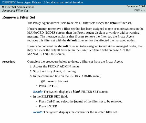
DEFINITY Proxy Agent Release 4.0 Installation and Administration
9 Filter Set AdministrationRemove a Filter Set
December 2001Page 210
Remove a Filter SetThe Proxy Agent allows users to delete all filter sets except the default filter set.
If users attempt to remove a filter set that has been assigned to one or more systems on the MANAGED NODES screen, then the Proxy Agent displays a window with a warning message. The message explains that if users remove the filter set, the Proxy Agent replaces this filter set with the default filter set for the affected the managed nodes.
If users do not want the default filter set to be assigned to individual managed nodes, then they can clear the default filter set in the Filter Set Name field on page A of the MANAGED NODES screen.
Procedure Complete the procedure below to delete a filter set from the Proxy Agent.
1 Access the PROXY ADMIN menu.
2 Stop the Proxy Agent, if running.
3 In the command line on the PROXY ADMIN menu,
• Type remove filter-set
• Press ENTER
Result: The system displays a blank FILTER SET screen.
4 In the FILTER SET field,
• Press Ctrl-Y and select the [name] of the filter set to be removed
• Press ENTER
Result: The system displays the criteria for the selected filter set.

DEFINITY Proxy Agent Release 4.0 Installation and Administration
9 Filter Set AdministrationRemove a Filter Set
December 2001Page 211
5 To remove the selected filter set, press Ctrl-E
Result: The system displays one of the options (a or b) below:
a If the filter set is not assigned to any managed node, then the system deletes the filter set and displays the PROXY ADMIN screen.
Go to step 7 below.
b If the filter set is assigned to one or more managed nodes, then system displays a window with a warning message. The message explains that the selected filter set will be replaced with the default filter set for the affected managed nodes. The message also contains a confirmation prompt: Do you wish to continue?
Go to step 6 to complete the procedure.
6 At the prompt, select one of the options (a or b) below:
a To remove the filter set, select Yes.
Result: The system removes the selected filter set and replaces it with the default filter set for the affected managed nodes. Then, the system displays the PROXY ADMIN screen.
b To cancel the remove request, select No.
Result: The system cancels the remove request and displays the PROXY ADMIN screen.

DEFINITY Proxy Agent Release 4.0 Installation and Administration
9 Filter Set AdministrationRemove a Filter Set
December 2001Page 212
7 From the PROXY ADMIN menu, start the Proxy Agent.
8 Display the STATUS screen.
• Verify the Proxy Agent is active
• Press Ctrl-X to exit the screen
Result: The system closes the STATUS screen and displays the PROXY ADMIN menu.

DEFINITY Proxy Agent Release 4.0 Installation and AdministrationDecember 2001
Page 21310 10Default Login Administration
IntroductionThe DEFAULT LOGIN screen allows users to enter a system-wide default login and password or Access Security Gateway (ASG) key for DEFINITY systems. The system automatically displays the login and allows the user to modify the password on page F of the MANAGED NODES screen. This feature reduces the time to administer large numbers of new DEFINITYs on the Proxy Agent. With this feature, users do not have to manually connect to the system on the COMMUNICATION MANAGER screen and save the login data.
The DEFAULT LOGIN screen allows users to enter a system-wide default login and password or Access Security Gateway (ASG) key for DEFINITY systems. The Proxy Agent automatically displays the login and allows the user to modify the password on page F of the MANAGED NODES screen.
This feature reduces the time to administer large numbers of new DEFINITYs on the Proxy Agent. With this feature, users do not have to manually connect to the system on the COMMUNICATION MANAGER screen and save the login data.

DEFINITY Proxy Agent Release 4.0 Installation and Administration
10 Default Login AdministrationIntroduction
December 2001Page 214
Users can change the default login data for individual DEFINITYs on page F of the MANAGED NODES screen.
! SECURITY ALERT:When users enter the data in the Password/ASG Key field, the characters that appear are periods. The periods only appear in the field during the time that the user is entering the password or ASG key. When users return to the screen, the system displays only the data in the Login field. For security reasons, the Proxy Agent stores the password or ASG key but leaves the Password/ASG Key field blank.
ASG login For DEFINITY systems that are protected by the ASG system, the Proxy Agent uses the default ASG Key to automatically generate a response to a challenge when connecting automatically to a DEFINITY system.
The procedure to "Connect to DEFINITY Systems with ASG" on page 272 contains the steps to manually enter the response and challenge to login to an ASG-protected DEFINITY system.

DEFINITY Proxy Agent Release 4.0 Installation and Administration
10 Default Login AdministrationReview of the Default Login Screen
December 2001Page 215
Review of the Default Login ScreenThe figure below shows the fields on the DEFAULT LOGIN screen.
Figure 23. Default Login screen
DEFAULT LOGIN(PROXY ADMIN) page 1 of 1change default-login
Login ID:
* Password/ASG Key:
browse
. . . . . . . .

DEFINITY Proxy Agent Release 4.0 Installation and Administration
10 Default Login AdministrationReview of the Default Login Screen
December 2001Page 216
Field descriptions The table below contains the field descriptions for the DEFAULT LOGIN screen.
Table 19. Default Login Screen
Field Description
Login ID Identifies the login name for the DEFINITY system.
The Proxy Agent displays the login ID on this screen and on page F of the MANAGED NODES screen when users administer new DEFINITYs on the Proxy Agent.
Field size: 20 characters
Validation: None
Default: Blank
(1 of 2)

DEFINITY Proxy Agent Release 4.0 Installation and Administration
10 Default Login AdministrationReview of the Default Login Screen
December 2001Page 217
Password/ASG Key Displays periods while entering the password or ASG key in this field for the default password or ASG key to access all DEFINITYs administered on the Proxy Agent.
The Proxy Agent saves the default password or ASG key but leaves the fields blank on the DEFAULT LOGIN screen. On page F of the MANAGED NODES screen, the Proxy Agent displays periods in the field.
For DEFINITY systems that are protected by the Access Security Gateway (ASG) system, the Proxy Agent uses the default ASG Key to automatically generate a response to a challenge when connecting automatically to a DEFINITY system.
Field size: 20 characters
Validation: None
Default: Blank
Table 19. Default Login Screen
Field Description
(2 of 2)

DEFINITY Proxy Agent Release 4.0 Installation and Administration
10 Default Login AdministrationAdminister the Default Login
December 2001Page 218
Administer the Default LoginThis section contains the procedure to administer the default login and password or ASG key on the DEFAULT LOGIN screen.
Required materials
Users need the following information and materials:
• DEFINITY login name
• DEFINITY password or ASG secret key
! SECURITY ALERT:For security reasons, the PA001 form does NOT contain the password or ASG secret key for the DEFINITY systems.
Procedure Complete the following steps to administer login data for new DEFINITY systems.
1 Access the PROXY ADMIN menu.
2 Stop the Proxy Agent, if running.
3 In the command line on the PROXY ADMIN menu,
• Type change default-login
• Press ENTER
Result: The system displays the DEFAULT LOGIN screen.
4 In the Login ID field, type [default login] used when adding new DEFINITY systems to the Managed Node screen.
5 In the Password/ASG Key field, type the [password or ASG secret key] used when adding new DEFINITY systems to the Managed Node screen.

DEFINITY Proxy Agent Release 4.0 Installation and Administration
10 Default Login AdministrationAdminister the Default Login
December 2001Page 219
6 Press Ctrl-E to submit the changes.
Result: The system saves the changes and displays the PROXY ADMIN menu.
7 New Installation. Complete the procedure to "Administer the Managed Nodes" on page 248.
8 Restart the Proxy Agent.

DEFINITY Proxy Agent Release 4.0 Installation and AdministrationDecember 2001
Page 22011 11Managed Nodes Administration
IntroductionThe MANAGED NODES screens contain the individual settings and options for each supported system that users administer on the Proxy Agent. Generally, users administer all management tasks from the MANAGED NODES screen.
The MANAGED NODES screen contains the individual values for each managed node administered on the Proxy Agent.
Users access the MANAGED NODES screen to execute the tasks listed below:
• Add new managed nodes to the Proxy Agent
• Change data for existing managed nodes
• Set the “forward alarms” option for managed nodes
• Select a filter set for individual managed nodes
• Select the Proxy Agent connection type and “start state” for individual managed nodes
• Change the submap type for individual managed nodes
• Change the system parameters of communication devices for individual managed nodes
• Reset the statistics counter for the Proxy Agent
• Select login ID and password/ASG key for new DEFINITYs administered on the Proxy Agent

DEFINITY Proxy Agent Release 4.0 Installation and Administration
11 Managed Nodes AdministrationIntroduction
December 2001Page 221
Default parameters
The Proxy Agent automatically loads the system-wide default parameters in the applications listed below:
• DEFAULT LOGIN
• FILTER SET
• ALARM DEVICES
• DEFAULT LOCATION
• CHANGE HARDWARE
When users add new managed nodes, the system displays the default parameters in the fields on the MANAGED NODES screens.
Users can change the parameters on the MANAGED NODES screen for individual managed nodes. The changes override the system default values only for the specific managed node.
SNMP polling During the installation of the Proxy Agent, users have the option to enable or disable SNMP polling:
• If users enable SNMP polling, then the Proxy Agent only supports 150 managed nodes.
• If users disable SNMP polling, then the Proxy Agent can support up to 600 managed nodes.
To change these options after the Proxy Agent has been installed, users must reinstall the Proxy Agent software and change the options at the appropriate prompts in the installation script.

DEFINITY Proxy Agent Release 4.0 Installation and Administration
11 Managed Nodes AdministrationIntroduction
December 2001Page 222
Static and Dynamic connections
The Proxy Agent supports both static and dynamic connections. A Proxy Agent supports only 30 active connections at a given time. The 30 active connections can be any combination of both static and dynamic connections.
However, if users administer 30 static connections, then the Proxy Agent will not allow the user to add any more managed devices, regardless of the connection type.
The following are examples of scenarios for assigning static and dynamic connections:
• If users assign 25 static connections, the system allows them to add 125 managed devices with dynamic connections. This frees 5 ports to connect to the 125 managed nodes with dynamic connections.
• If users assign 10 static connections, then the system allows them to add 140 managed devices with dynamic connections. This frees 20 ports to connect to 140 managed devices with dynamic connections.
Avaya recommends that if users collect hourly data on certain DEFINITY systems, then they should only administer 30 static connections to each Proxy Agent. This will ensure continuous and accurate data collection for those systems.
Users can resolve these limitations by adding additional Proxy Agents and then spreading the static connections across the Proxy Agents.

DEFINITY Proxy Agent Release 4.0 Installation and Administration
11 Managed Nodes AdministrationReview of the Managed Nodes Screen
December 2001Page 223
Review of the Managed Nodes Screen The MANAGED NODES screen is similar to a spreadsheet. The screen contains 40 pages, with 15 lines per page. The lines on each page are consecutively numbered 1 to 600 to identify each managed node that is connected to a specific Proxy Agent.
The example below shows the line numbers on the pages:
• Page 1 contains numbered lines 1 through 15
• Page 2 contains numbered lines 16 through 30, etc.
In addition, each of the 40 pages contains 5 subpages (a through e). The subpages contain fields to administer each managed node.
The example below shows the page number for subpages (1 through 40):
• Page 1 subpages are numbered: 1a/40, 1b/40, 1c/40, 1d/40, 1e/40
• Page 2 subpages are numbered: 2a/40, 2b/40, 2c/40, 2d/40, 2e/40, etc.

DEFINITY Proxy Agent Release 4.0 Installation and Administration
11 Managed Nodes AdministrationReview of the Fields on Page A
December 2001Page 224
Review of the Fields on Page AThe figure below shows page A of the MANAGED NODES screen. Page A contains the basic fields to administer managed nodes and the Proxy Agent.
Figure 24. Page A of the MANAGED NODES screen

DEFINITY Proxy Agent Release 4.0 Installation and Administration
11 Managed Nodes AdministrationReview of the Fields on Page A
December 2001Page 225
Page A field descriptions
The table below contains the field descriptions for page A of the MANAGED NODES screen. .
Table 20. Page A of the Managed Nodes screen
Field Description
NODE NAME Identifies the name of the system that users administer on Proxy Agent as a managed node. The node name occupies the same line number on each of the five (5) lettered pages. Avaya recommends that you use all lower-case letters to define the Node Name.
The node name on the Proxy Agent must match the managed node name on the Network Management System (NMS).
Users can change the node name without having to re-enter data in the other fields.
If users delete the NODE NAME field, the system automatically clears the data from all fields in the numbered row on each of the 5 lettered subpages.
Field size: 9 characters.
Required field.
(1 of 7)

DEFINITY Proxy Agent Release 4.0 Installation and Administration
11 Managed Nodes AdministrationReview of the Fields on Page A
December 2001Page 226
NODE TYPE Identifies the type of managed node that is associated with a specific Proxy Agent.
The HELP list (Ctrl-Y) contains the valid options below:
ECS (default) = DEFINITY release 5 and later
G3 = DEFINITY G3V4
DEFONE = DEFINITY One
IP600 = IP600
MCU = Multipoint Conferencing Unit
* DAUDIX = DEFINITY AUDIX
* IAUDIX = Intuity AUDIX
* INTRCHG = Intuity Interchange
* CMS = Call Management System
* CNVRSNT = CONVERSANT
* If users select one of these systems, the screen does not display the following fields: Reset Count; Start State; Start Type; or Dynamic Timeout.
Table 20. Page A of the Managed Nodes screen
Field Description
(2 of 7)

DEFINITY Proxy Agent Release 4.0 Installation and Administration
11 Managed Nodes AdministrationReview of the Fields on Page A
December 2001Page 227
FORWARDALARMS
Indicates the alarm forwarding feature is on or off for the individual managed nodes.
The HELP list (Ctrl-Y) contains the valid options below:
Y = (yes) alarm forwarding is on
N = (no) alarm forwarding is off
The default values differ for type of managed nodes:
Y = default for G3, MCU, DAUDIX, IAUDIX, INTRCHG, CMS, and CNVRSNT
N = default for ECS, IP600, and DEFINITY One
Note: If users turn on the FORWARD ALARM option, they should verify that the ALARM DEVICES screen is administered to receive alarms from managed nodes and to forward alarms to INADS. Forwarding is subject to filtering as defined in filter set field.
PRODUCT IDFOR ALARMS
Identifies the product identification (ID) number of the managed node.
Size: 10 characters
Required field.
Table 20. Page A of the Managed Nodes screen
Field Description
(3 of 7)

DEFINITY Proxy Agent Release 4.0 Installation and Administration
11 Managed Nodes AdministrationReview of the Fields on Page A
December 2001Page 228
FILTER SET NAME (IF REQ)
Identifies the name of the filter set that the Proxy Agent applies to alarms received from the managed node. The Proxy Agent assigns the default filter set to new managed nodes.
To activate the filter set features, users must administer the screens described below:
• Users must administer the alarm source and alarm destination fields on the ALARM DEVICES screen. Refer to "Administer the Alarm Device" on page 181.
• Users can add, change, or remove filters on the FILTER SET screen. For new installations, the default filter set is blank. Users can add filtering criteria to the default filter set or leave it blank. Refer to "Administer the Filter Sets" on page 202.
• Users must also select “Y” (yes) in the FORWARD ALARM field on the page A of the MANAGED NODES screen. Refer to procedures to "Administer the Managed Nodes" on page 248.
Size: 10 characters
Default: “default” is the name of the default filter set.
Table 20. Page A of the Managed Nodes screen
Field Description
(4 of 7)

DEFINITY Proxy Agent Release 4.0 Installation and Administration
11 Managed Nodes AdministrationReview of the Fields on Page A
December 2001Page 229
STARTTYPE
Identifies the type of connection between the Proxy Agent and a managed node.
The HELP list (Ctrl-Y) contains the valid options below:
static (default)
dynamic (see DYNAMIC TIMEOUT field)
A static connection maintains a continuous link for 24 hours per day, 7 days per week. Select static connections to monitor critical managed nodes.
A dynamic connection maintains a temporary link with the managed node on an as-needed basis. Select dynamic connections to monitor less critical managed nodes.
A dynamic connection stays up as long as the Proxy Agent is actively processing SNMP requests and then times-out after a specified period.
The Network Management System (NMS) does not poll for health data if a dynamic connection is assigned to a managed node.
Table 20. Page A of the Managed Nodes screen
Field Description
(5 of 7)

DEFINITY Proxy Agent Release 4.0 Installation and Administration
11 Managed Nodes AdministrationReview of the Fields on Page A
December 2001Page 230
STARTSTATE
Identifies the connection state of the Proxy Agent at the time the user starts the Proxy Agent.
The HELP list (Ctrl-Y) contains the valid options below:
• init = initiates the connection types as defined below:
– Starts the static connection to the managed node
– Places the dynamic connection in an idle state to be initiated by minor or major alarms from the managed node
• off = (default) indicates that the connections are turned off
The Proxy Agent only supports 30 active connections at a given time. The 30 active connections can be a combination of static and dynamic connections.
The valid start states are:
• static init or static off
• dynamic init or dynamic off
Table 20. Page A of the Managed Nodes screen
Field Description
(6 of 7)

DEFINITY Proxy Agent Release 4.0 Installation and Administration
11 Managed Nodes AdministrationReview of the Fields on Page A
December 2001Page 231
DYNAMICTIMEOUT
Identifies the number of minutes that a dynamic connection can be inactive before the Proxy Agent drops the connection to a managed node.
The HELP list (Ctrl-Y) contains the valid minute below:
5 (default)
15
30
60
120
RESETCOUNT
Allows users to reset the status counters to zero.
While the Proxy Agent is running, the counters track the number of attempts, connections, requests, responses, and errors that occur.
The Proxy Agent updates the numbers from the counters on the STATUS screen.
The HELP list (Ctrl-Y) contains the valid options below:
N = no (default) -- do not reset counters
Y = yes to reset the status counters to zero
Table 20. Page A of the Managed Nodes screen
Field Description
(7 of 7)

DEFINITY Proxy Agent Release 4.0 Installation and Administration
11 Managed Nodes AdministrationReview of the Fields on Page B
December 2001Page 232
Review of the Fields on Page B The figure below shows page B of the MANAGED NODES screen. Page B contains the fields to administer the transmission options for the communication devices that connect the Proxy Agent to each managed node.
Note: It is recommended that the values of these fields remain at their default values, unless a Avaya representative instructs you to change their value(s).
!WARNING:!All active IP connections (emulation or cut-through) are dropped when you save changes to the MANAGED NODES screen.

DEFINITY Proxy Agent Release 4.0 Installation and Administration
11 Managed Nodes AdministrationReview of the Fields on Page B
December 2001Page 233
Figure 25. Page B of the MANAGED NODES screen

DEFINITY Proxy Agent Release 4.0 Installation and Administration
11 Managed Nodes AdministrationReview of the Fields on Page B
December 2001Page 234
Page B field descriptions
The table below contains the field descriptions for page B of the MANAGED NODES screen.
Table 21. Page B of the Managed Nodes screen
Field Description
NODENAME
Identifies the name of the managed node. The node name occupies the same line number on each of the lettered pages.
SPEED Identifies the baud rate for the communication device that connects the Proxy Agent to each managed node.
The HELP list (Ctrl-Y) contains the valid options below:
9600 (default)
4800
2400
1200
STOPBITS
Identifies the stop bit setting on the communication device.
The HELP list (Ctrl-Y) contains the valid options below:
1 (default)
2
(1 of 2)

DEFINITY Proxy Agent Release 4.0 Installation and Administration
11 Managed Nodes AdministrationReview of the Fields on Page B
December 2001Page 235
FLOWCNTRL
Identifies the flow control setting on the communication device.
The HELP list (Ctrl-Y) contains the valid options below:
n (no) (default) -- Turn-off
y (yes) -- Turn-on
PARITY Identifies the parity setting on the communication device.
The HELP list (Ctrl-Y) contains the valid options below:
none (default)
odd
even
CHARSIZE
Identifies the character size setting on the communication device.
The HELP list (Ctrl-Y) contains the valid options below:
8 (default)
7
Table 21. Page B of the Managed Nodes screen
Field Description
(2 of 2)

DEFINITY Proxy Agent Release 4.0 Installation and Administration
11 Managed Nodes AdministrationReview of the Fields on Page C
December 2001Page 236
Review of the Fields on Page CThe figure below shows page C of the MANAGED NODES screen. Page C contains the submap type and location of the individual managed nodes.
Figure 26. Page C of the MANAGED NODES screen

DEFINITY Proxy Agent Release 4.0 Installation and Administration
11 Managed Nodes AdministrationReview of the Fields on Page C
December 2001Page 237
Page C field descriptions
The table below contains the field descriptions for Page C of the MANAGED NODES screen.
Table 22. Page C of the Managed Nodes screen
Field Description
NODENAME
Identifies the name of the managed node. The node name occupies the same line number on each of the lettered pages.
SUBMAPTYPE
Identifies the type of location map to display on the Network Management System (NMS).
The HELP list (Ctrl-Y) contains the valid options below:
generic (default)
usa (see associated STATE field)
custom (see associated SUBMAP NAME field)
Field size: 7 characters
(1 of 2)

DEFINITY Proxy Agent Release 4.0 Installation and Administration
11 Managed Nodes AdministrationReview of the Fields on Page C
December 2001Page 238
STATE Identifies the name of the state where a managed node is located on the USA map.
The STATE field only displays if the user selects the usa option in the SUBMAP TYPE field.
The HELP list (Ctrl-Y) contains the valid options for this field which include all 50 states.
The default option is set on the DEFAULT LOCATION screen. Users can change the State name for individual managed nodes
Field size: 14 characters
SUBMAPNAME
Identifies the name of the custom location submap for individual managed nodes.
The SUBMAP NAME field only displays if the user selects the custom option in the SUBMAP TYPE field.
Field size: 40 characters. The system accepts any name that users type the in the SUBMAP NAME field.
Table 22. Page C of the Managed Nodes screen
Field Description
(2 of 2)

DEFINITY Proxy Agent Release 4.0 Installation and Administration
11 Managed Nodes AdministrationReview of the Fields on Pages D and E
December 2001Page 239
Review of the Fields on Pages D and EPages D and E of the MANAGED NODES screen contain the same fields to administer the dialing orders and dial strings that the Proxy Agent uses to connect with each managed node.
The figure below shows page D of the MANAGED NODES screen.
Figure 27. Page D of the MANAGED NODES screen

DEFINITY Proxy Agent Release 4.0 Installation and Administration
11 Managed Nodes AdministrationReview of the Fields on Pages D and E
December 2001Page 240
The figure below shows page E of the MANAGED NODES screen.
Figure 28. Page E of the MANAGED NODES screen

DEFINITY Proxy Agent Release 4.0 Installation and Administration
11 Managed Nodes AdministrationReview of the Fields on Pages D and E
December 2001Page 241
Pages D and E field descriptions
The table below contains the field description for pages D and E of the MANAGED NODES screen.
Table 23. Pages D and E of the Managed Nodes screen
Field Description
NODENAME
Identifies the name of the managed node. The node name occupies the same line number on each of the lettered pages.
(1 of 4)

DEFINITY Proxy Agent Release 4.0 Installation and Administration
11 Managed Nodes AdministrationReview of the Fields on Pages D and E
December 2001Page 242
DIALINGORDER
Specifies which dial string the Proxy Agent will use to connect to a managed node.
The Proxy Agent will always use the number 1 dial string first. If the number 1 dial string is busy or out-of-order, then the Proxy Agent will use the number 2 dial string, if number 2 exists.
For example, use Dialing Order 1 for Dial String /dev/ttyp20:135.9.142.50 (for SNMP) and use Dialing Order 2 for Dial String /dev/ttyp120:135.9.142.50 (for cut-through).
The HELP list (Ctrl-Y) contains the valid options below:
1 -- required field (default)
2 -- optional field
Generally, users designate page D as the number 1 dialing order and page E as the number 2 dialing order.
If users enter two dial strings, they can change the dialing orders between the subpages D and E. One of the dial strings must contain the number 1 in the DIALING ORDER column.
Table 23. Pages D and E of the Managed Nodes screen
Field Description
(2 of 4)

DEFINITY Proxy Agent Release 4.0 Installation and Administration
11 Managed Nodes AdministrationReview of the Fields on Pages D and E
December 2001Page 243
DIAL STRING Specifies the dial string that the Proxy Agent uses to connect to a managed node.
A dial string can be an extension number, the telephone number, or the area code and telephone number.
The following are examples of valid dial strings:
• Dial string can be a combination of the area code, phone number, and extension. Examples: 3035551212; 5551212; or 1212
• Device path (/dev/tty001)
• Device path and dial string (/dev/tty001:3035551212)
Device path and IP address ( (port number is optional) (/dev/ttyp20:135.9.142.50)
Table 23. Pages D and E of the Managed Nodes screen
Field Description
(3 of 4)

DEFINITY Proxy Agent Release 4.0 Installation and Administration
11 Managed Nodes AdministrationReview of the Fields on Pages D and E
December 2001Page 244
DIAL STRING (continued)
Required field for the number 1 dialing order for the primary dial string.
Required field for the number 2 dialing order only if users entered a 2 in the DIALING ORDER field for the secondary dial string.
The system recognizes an IP connection as a device even though no physical device exists. Use a psuedo-device address for an IP connection. For example, to connect to a DEFINITY One at IP address 135.9.142.50 using psuedo-device/dev/ttyp10, enter /dev/ttyp/10:135.9.142.50-23. The default port number for a TCP telnet connection is 23.
Table 23. Pages D and E of the Managed Nodes screen
Field Description
(4 of 4)

DEFINITY Proxy Agent Release 4.0 Installation and Administration
11 Managed Nodes AdministrationReview of the Fields on Page F
December 2001Page 245
Review of the Fields on Page FThe figure below shows page F of the MANAGED NODES screen. Page F contains the default login ID for DEFINITY systems from the DEFAULT LOGIN screen. The system does not display the password or ASG key entered on the DEFAULT LOGIN screen.
Figure 29. Page F of Managed Nodes screen

DEFINITY Proxy Agent Release 4.0 Installation and Administration
11 Managed Nodes AdministrationReview of the Fields on Page F
December 2001Page 246
Page F field descriptions
The table below contains the field descriptions for Page F of the MANAGED NODES screen.
Table 24. Page F of the Managed Nodes screen
Field Description
NODENAME
Identifies the name of the managed node. The node name occupies the same line number on each of the lettered pages.
Login ID Identifies the login name for the DEFINITY system.
The Proxy Agent displays the login ID data for DEFINITY systems.
The feature reduces the time to administer large numbers of new DEFINITYs on the Proxy Agent. With this feature, users do not have to manually connect to the system on the COMMUNICATION MANAGER screen and save the login data.
To override the default login ID from the DEFAULT LOGIN screen, users can change the login ID for individual DEFINITY systems on page F.
Field size: 20 characters
Validation: None
Default: Blank
(1 of 2)

DEFINITY Proxy Agent Release 4.0 Installation and Administration
11 Managed Nodes AdministrationReview of the Fields on Page F
December 2001Page 247
Password/ASG Key Displays periods in field as the password or ASG key is entered.
The Proxy Agent saves the default password or ASG key that users administered on the DEFAULT LOGIN screen. For security reasons, the Proxy Agent displays periods in the field on the MANAGED NODES screen.
For DEFINITY systems that are protected by the Access Security Gateway (ASG) system, the Proxy Agent automatically generates the response to the challenge when users administer new DEFINITYs on the Proxy Agent.
To override the default password or ASG Key from the DEFAULT LOGIN screen, users can change the password or ASG secret key for individual DEFINITY systems on page F.
Field size: 20 characters
Validation: None
Default: Blank
Table 24. Page F of the Managed Nodes screen
Field Description
(2 of 2)

DEFINITY Proxy Agent Release 4.0 Installation and Administration
11 Managed Nodes AdministrationAdminister the Managed Nodes
December 2001Page 248
Administer the Managed Nodes The MANAGED NODES screen provides an overview of the configuration for each managed node that users administer on the Proxy Agent.
This section contains the procedures to:
• Add new managed nodes to the Proxy Agent and save the login data
• Change data for individual managed nodes
• Delete existing managed nodes
Procedure The procedures below contain the steps to add or change managed nodes and one step to delete a managed node.
!WARNING:!All active IP connections (emulation or cut-through) are dropped when you save changes to the MANAGED NODES screen. Avaya recommends that you do not make manual changes to the dpanetd configuration file.
The examples in the procedure below show default values in the fields.
Note: To complete the fields, refer to the Managed Nodes section of the PA001 form.
1 Access the PROXY ADMIN menu.
2 Stop the Proxy Agent, if running.

DEFINITY Proxy Agent Release 4.0 Installation and Administration
11 Managed Nodes AdministrationAdminister the Managed Nodes
December 2001Page 249
3 In the command line on the PROXY ADMIN menu,
• Type change managed-nodes
• Press ENTER
Result: The system displays the page A of the MANAGED NODES screen.
MANAGED NODES
NODENAME
1:*e2:3:4:5:6:7:8:9:
10:11:12:13:14:15:
cs1g3mcudaudix1iaudix1intrchg1cms1conv1
NODETYPEECSG3MCUDAUDIXIAUDIXINTRCHGCMSCNVRSNT
PRODUCT IDFOR ALARMS11111111111222222222133333333322111111112222222222223333333320999999992188888888
RESETCOUNT
nnn
STARTSTATEinitinitoff
STARTTYPEstaticdynamicstatic
defaultfset1
defaultdefaultdefaultdefaultdefault
FILTERSET NAME
(IF REQ)FORWARDALARMS
nyyyyyyy
60
DYNAMICTIMEOUTMINUTES
sdnmmgna LJK 092299
(PROXY ADMIN) page 1a/40change managed-nodes

DEFINITY Proxy Agent Release 4.0 Installation and Administration
11 Managed Nodes AdministrationAdminister the Managed Nodes
December 2001Page 250
4 On page A, access the appropriate page number (1 through 40). In the NODE NAME column, execute one of the options below:
• To add a new managed node: Go to the next blank line and follow the steps below.
• To change a managed node: Go to the line number for that managed node. Then, go to the fields to be changed and make the appropriate changes on each subpage.
• To delete an existing managed node: Go to the line number for that managed node. Press the SPACE BAR. The system deletes the managed node and clears the fields on all subpages for that line.
5 On page A, go to the first blank line and complete the fields below to add a new managed node. The fields contain the default settings.
NODE NAME: Type the [system name]
NODE TYPE: ECS (default).
FORWARD ALARMS: n (default for ECS, IP600, and DEFINITY One); y (default for all other node types)
PRODUCT ID FOR ALARMS: Type the [product/alarm ID] for the node type
FILTER SET NAME: default -- Execute one of the options (a or b) below:
a To select a different filter name, press Ctrl-Y to display the options list; highlight a filter name; and press ENTER
b To clear the field of any filter name, press the SPACE BAR
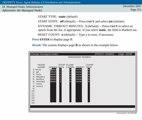
DEFINITY Proxy Agent Release 4.0 Installation and Administration
11 Managed Nodes AdministrationAdminister the Managed Nodes
December 2001Page 251
START TYPE: static (default)
START STATE: off (default) -- Press Ctrl-Y and select init (initiate)
DYNAMIC TIMEOUT MINUTES: 5 (default) -- Press Ctrl-Y to select an option from the list, if appropriate. If you select static, the field is blanked out.
RESET COUNT: n (default) -- Type y to reset, if necessary
Press ENTER to display page B.
Result: The system displays page B as shown in the example below.
MANAGED NODES
NODENAME
1:*ecs12: g33: mcu4: daudix15: iaudix16: intrchg17: cms18: conv19:
10:11:12:13:14:15:
SPEED>9600
96009600960096009600
STOPBITS
111111
FLOWCNTRL
nnnnnn
CHARSIZE
888888
PARITYnonenonenonenonenonenone
sdnmmgnb LJK 092299
(PROXY ADMIN) page 1b/40change managed-nodes
9

DEFINITY Proxy Agent Release 4.0 Installation and Administration
11 Managed Nodes AdministrationAdminister the Managed Nodes
December 2001Page 252
6 On page B, change the values of the communication devices for individual managed nodes, if necessary.
NODE NAME: (carried over to each page)
SPEED: 9600 (check the PA001 form)
STOP BITS: 1
FLOW CNTRL: n
PARITY: none
CHAR SIZE: 8
Press ENTER to display page C.
Result: The system displays page C of the Managed Nodes screen.
MANAGED NODES
NODENAME
1:*ecs12: g33: mcu4: daudix15: iaudix16: intrchg17: cms18: conv19:
10:11:12:13:14:15:
SUBMAPTYPE
genericusacustomgenericgenericgenericgenericgeneric
SUBMAPNAME
Africa
sdnmmgnc LJK 092299
(PROXY ADMIN) page 1c/40change managed-nodes
>STATE
Alabama

DEFINITY Proxy Agent Release 4.0 Installation and Administration
11 Managed Nodes AdministrationAdminister the Managed Nodes
December 2001Page 253
7 On page C, change the location for each managed node, where appropriate.
Generic locationSUBMAP TYPE: generic (default)
USA locationSUBMAP TYPE: usa
STATE: Alabama (default) Press Ctrl-Y to select a state from the list
Custom locationSUBMAP TYPE: custom
SUBMAP NAME: Type the [location name]
Press ENTER to display page D.
Result: The system displays page D as shown in the example below.

DEFINITY Proxy Agent Release 4.0 Installation and Administration
11 Managed Nodes AdministrationAdminister the Managed Nodes
December 2001Page 254
MANAGED NODES
NODENAME
9:10:11:12:13:14:15:
1:*ecs12: g33: mcu4: daudix15: iaudix16: intrchg17: cms18: conv1
DIALINGORDER> 1
11111
DIAL STRING/dev/tty1a1:1234/dev/tty1a2:9876543/dev/tty1a3:555123890199999999999999999999
sdnmmgnd LJK 092399
(PROXY ADMIN) page 1d/40change managed-nodes

DEFINITY Proxy Agent Release 4.0 Installation and Administration
11 Managed Nodes AdministrationAdminister the Managed Nodes
December 2001Page 255
8 On page D, complete the fields for the primary communication device. The Proxy Agent uses this device to connect to the managed node.
NODE NAME: (carried over to each page)
DIALING ORDER: 1
– Use this field to allow cut-through emulation to the systems when the Proxy Agent is active.
Enter 1 (default) for the Dial String used by the Proxy Agent SNMP. Enter 2 to identify a different pseudo-device for the connection application for the cut-through. The dial strings (devices) for Dialing Order entries 1 and 2 must be different.
DIAL STRING: Type the [dial string] for the primary device. Go to the PA001 form and refer to the Dial String 1 field on the Managed Nodes section.
Press ENTER to display page E.
Result: The system displays page E as shown in the example below.

DEFINITY Proxy Agent Release 4.0 Installation and Administration
11 Managed Nodes AdministrationAdminister the Managed Nodes
December 2001Page 256
MANAGED NODES
NODENAME
1:*ecs12: g33: mcu4: daudix15: iaudix16: intrchg17: cms18: conv19:
10:11:12:13:14:15:
DIALINGORDER
222
DIAL STRING/dev/tty1a4:5678/dev/tty1a5:9872222/dev/tty1a6:5559876666
sdnmmgne LJK 092399
(PROXY ADMIN) page 1e/40change managed-nodes
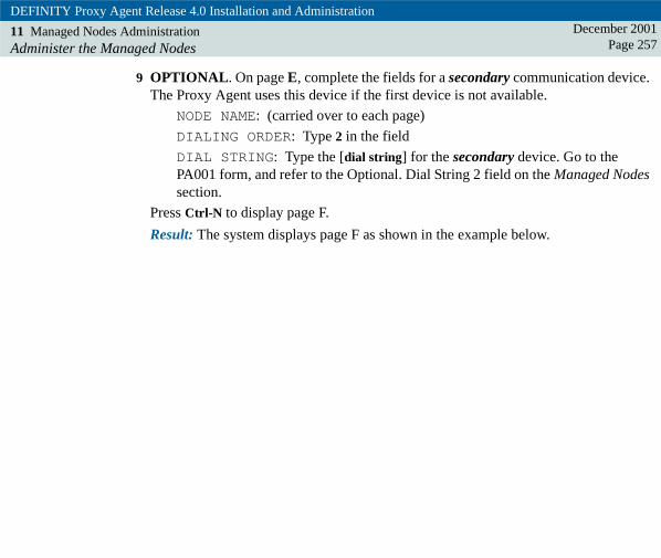
DEFINITY Proxy Agent Release 4.0 Installation and Administration
11 Managed Nodes AdministrationAdminister the Managed Nodes
December 2001Page 257
9 OPTIONAL. On page E, complete the fields for a secondary communication device. The Proxy Agent uses this device if the first device is not available.
NODE NAME: (carried over to each page)
DIALING ORDER: Type 2 in the field
DIAL STRING: Type the [dial string] for the secondary device. Go to the PA001 form, and refer to the Optional. Dial String 2 field on the Managed Nodes section.
Press Ctrl-N to display page F.
Result: The system displays page F as shown in the example below.

DEFINITY Proxy Agent Release 4.0 Installation and Administration
11 Managed Nodes AdministrationAdminister the Managed Nodes
December 2001Page 258
MANAGED NODES
NODENAME
1: ecs12: g33: mcu4: daudix15: iaudix16: intrchg17: cms18: conv19:
10:11:12:13:14:15:
sdnmmann LJK 092399
(PROXY ADMIN) page 1f/40change managed-nodes
LOGIN IDbrowsesnmpcraft
PASSWORD/ASG KEY. . . . . . . .. . . . .. . . . . .

DEFINITY Proxy Agent Release 4.0 Installation and Administration
11 Managed Nodes AdministrationAdminister the Managed Nodes
December 2001Page 259
10 The fields on page F contain the default login data from the DEFAULT LOGIN screen for new DEFINITY systems, as show in the example below.
NODE NAME: (carried over to each page)
LOGIN ID: [system name] for the new DEFINITY system
PASSWORD/ASG KEY: [...........] periods are displayed as the password or ASG secret key is entered.
11 Press Ctrl-E to submit the data.
Result: The system saves the data and displays the PROXY ADMIN menu.
12 From the PROXY ADMIN menu, start the Proxy Agent.
13 Display the STATUS screen.
• Verify the Proxy Agent is active
• Press Ctrl-X to exit the screen
Result: The system closes the STATUS screen. Then, displays the PROXY ADMIN menu.

DEFINITY Proxy Agent Release 4.0 Installation and AdministrationDecember 2001
Page 26012 12Communication Application
IntroductionThe Communication application allows manual connection of the Proxy Agent to managed nodes to troubleshoot connection problems. procedures to manually connect and disconnect the Proxy Agent to and from the managed nodes. The procedures contain the login prompts to access managed nodes and DEFINITY systems that are protected by the Access Security Gateway (ASG) software.
The purpose of the Communication application is to execute the specific tasks listed below:
• To troubleshoot connections between the Proxy Agent and managed nodes.
• To connect to one or two managed nodes before starting an administration session from the EMULATION screen.
In all other instances, users access the MANAGED NODES screen to initiate the Proxy Agent connection with individual managed nodes.
Connection procedures
This chapter contains two types of connection procedures to manually log in to the managed nodes.
• "Connect to Managed Nodes" on page 266
• "Connect to DEFINITY Systems with ASG" on page 272
The login prompts display in separate popup windows on the COMMUNICATION MANAGER screen.

DEFINITY Proxy Agent Release 4.0 Installation and Administration
12 Communication ApplicationIntroduction
December 2001Page 261
Saving login data Users should administer the DEFAULT LOGIN screen to save the login data for new DEFINITY systems. Refer to the procedure to "Administer the Default Login" on page 218,
When users administer new DEFINITY systems, the Proxy Agent displays the default login data on page F of the MANAGED NODES screen. Users do not have to complete the procedures on the COMMUNICATION MANAGER screen to save new login data.
At the COMMUNICATION MANAGER screen, generally users should not save the login data unless the system prompts them to enter a new password. The prompt to resave login data displays if the “password aging” feature is enabled on the managed node. The system permanently stores the login data until users change and save login data at a later time.
Emulation sessions
The EMULATION application allows users to directly connect with one managed node and conduct an administration session on the system. Therefore, users do not need to execute the connection procedures in this chapter. Refer to "Connect to Two Managed Nodes" on page 290.
Users can connect to two managed nodes before starting an administration session from the EMULATION application. The EMULATION application allows users to start and quit a session with the managed nodes without dropping the connections.

DEFINITY Proxy Agent Release 4.0 Installation and Administration
12 Communication ApplicationIntroduction
December 2001Page 262
To conduct an emulation session with two managed nodes connections, users must execute the procedures in the order listed below:
• Access the COMMUNICATION MANAGER screen and connect the two managed nodes. Do not save the login data. Refer to the appropriate procedure below:
– "Connect to Managed Nodes" on page 266
– "Connect to DEFINITY Systems with ASG" on page 272
• Access the EMULATION application and conduct the administration session. Refer to "Connect to Two Managed Nodes" on page 290.
• Access the COMMUNICATION MANAGER screen and disconnect the managed nodes at the end of the administration session. Refer to "Disconnect from Managed Nodes" on page 284.

DEFINITY Proxy Agent Release 4.0 Installation and Administration
12 Communication ApplicationReview of the Communication Manager Screen
December 2001Page 263
Review of the Communication Manager ScreenThe figure below shows the COMMUNICATION MANAGER screen with the two connections fields.
Figure 30. Communication Manager screen
COMMUNICATION MANAGER
sdnmcomm LJK 040798
(COMMUNICATION) Page 1 of 1
CONNECT TO STATUSPORTTYPE
Connection 1Connection 2
> RS232RS232
IDLEIDLE

DEFINITY Proxy Agent Release 4.0 Installation and Administration
12 Communication ApplicationReview of the Communication Manager Screen
December 2001Page 264
Field descriptions The table below contains the descriptions for the fields on the COMMUNICATION MANAGER screen.
Table 25. Communication Manager screen
Field Description
CONNECT TO Fields
Connection 1 Contains the first managed node that is currently connected to the Proxy Agent.
The field is blank if a managed node is NOT currently connected.
The Help list (Ctrl-Y) contains the valid options for this field:
• List of all managed nodes administered on the Proxy Agent
• The disconnect command if a managed node is currently connected. The disconnect command does not appear on the list if the field is blank.
(1 of 2)

DEFINITY Proxy Agent Release 4.0 Installation and Administration
12 Communication ApplicationReview of the Communication Manager Screen
December 2001Page 265
Connection 2 Contains the second managed node that is currently connected to the Proxy Agent.
The field is blank if a second managed node is not currently connected.
The Help list (Ctrl-Y) contains the valid options for this field:
• List of all managed nodes administered on the Proxy Agent
• The disconnect command if a managed node is currently connected. The disconnect command does not appear on the list if the field is blank.
PORT TYPE Identifies the type of communication port the Proxy Agent uses to connect to the managed node.
This is a view-only field.
STATUS Identifies the current state of the Proxy Agent connection to a managed node.
The valid options for the STATUS states include:
IDLE -- A dynamic connection is not connected
CONNECTED -- A managed node is connected
This is a view-only field.
Table 25. Communication Manager screen
Field Description
(2 of 2)

DEFINITY Proxy Agent Release 4.0 Installation and Administration
12 Communication ApplicationConnect to Managed Nodes
December 2001Page 266
Connect to Managed NodesThis section contains the procedure to manually login to one or two managed nodes and execute the tasks below:
• To troubleshoot connections between the Proxy Agent and managed nodes.
• To connect to two managed nodes before starting an administration session from the EMULATION screen.
Required materials
Users must know the information listed below to complete the procedure:
• Login name for each managed node
• Password to access the each managed node
Procedure Complete the procedure below to manually login to managed nodes.
1 Access the Proxy Agent MAIN MENU.
In the command line,
• Type communication
• Press ENTER
Result: The system displays the COMMUNICATION MANAGER screen, as shown in the example below.

DEFINITY Proxy Agent Release 4.0 Installation and Administration
12 Communication ApplicationConnect to Managed Nodes
December 2001Page 267
COMMUNICATION MANAGER
sdnmcomm LJK 040798
(COMMUNICATION) Page 1 of 1
CONNECT TO STATUSPORTTYPE
Connection 1Connection 2
> RS232RS232
IDLEIDLE

DEFINITY Proxy Agent Release 4.0 Installation and Administration
12 Communication ApplicationConnect to Managed Nodes
December 2001Page 268
2 In the Connection 1 field, execute one of the options (a or b) below:
a If the field is blank, connect the first managed node:
– Press Ctrl-Y to display the Help list
– Select a [managed node] from the list
– Press ENTER
b If the field contains a connection that you want to change, then disconnect the managed node and select a different managed node:
– Press Ctrl-Y to display the Help list
– Select disconnect to drop the current connection
– Press ENTER
– Press Ctrl-Y again
– Select a different [managed node name] for the first connection
– Press ENTER
Result: The system displays the node name in the Connection 1 field.
3 Optional. In the Connection 2 field, execute one of the options (a or b) in step 2 above to connect to a second managed node:
Result: The system displays the node name in the Connection 2 field.
Note: If users select a second node name in the Connection 2 field, the system displays the login windows for each of the selected node names. Users must repeat steps 4 through 8 below for the second connection.

DEFINITY Proxy Agent Release 4.0 Installation and Administration
12 Communication ApplicationConnect to Managed Nodes
December 2001Page 269
4 Press Ctrl-E to submit the changes.
Result: The system saves the changes and displays the login window below for the node name selected in the Connection 1 field.
COMMUNICATION MANAGER
sdnmlogn LJK 092399
(COMMUNICATION) Page 1 of 1
CONNECT TOg3
STATUSPORTTYPE
Connection 1Connection 2
> RS232RS232
IDLEIDLE
Connecting to g3
Login:
Waiting for modem initialization - (33 secs until Modem Timeout)

DEFINITY Proxy Agent Release 4.0 Installation and Administration
12 Communication ApplicationConnect to Managed Nodes
December 2001Page 270
5 In the Login field,
• Type the [managed node login]
• Press ENTER
Result: The system displays the password window below.
COMMUNICATION MANAGER
sdnmpass LJK 092399
(COMMUNICATION) Page 1 of 1
CONNECT TOg3
STATUSPORTTYPE
Connection 1Connection 2
> RS232RS232
IDLEIDLE
Connecting to g3
Login: [node login]Password:Save Login/Password for SNMP access (y/n)? n
Waiting for connection login - (19 secs. until Connection Timeout)

DEFINITY Proxy Agent Release 4.0 Installation and Administration
12 Communication ApplicationConnect to Managed Nodes
December 2001Page 271
6 In the Password field,
• Type the [managed node password]
• Press ENTER
Result: The system displays the prompt:Save Login/Password for SNMP access (y/n)? n
7 Execute one of the options (a or b) below:
a To save new login data the first time,
– Press Y (yes)
– Press ENTER
b To connect to two managed nodes for an administration session, do NOT save the login data if the data has been previously saved:
– Press ENTER to select N (no)
Result: The system displays the message:Negotiating protocol communication
Then, the system displays the Proxy Agent MAIN MENU that contains the confirmation message: Connected To [managed node]
8 At the completion of the task, complete the procedure to "Disconnect from Managed Nodes" on page 284.

DEFINITY Proxy Agent Release 4.0 Installation and Administration
12 Communication ApplicationConnect to DEFINITY Systems with ASG
December 2001Page 272
Connect to DEFINITY Systems with ASGThis section contains the procedure to manually connect to DEFINITY systems that are protected by Access Security Gateway (ASG) and execute these tasks:
• To troubleshoot connections between the Proxy Agent and managed nodes.
• To connect to two managed nodes before starting an administration session from the EMULATION screen.
The ASG login procedure includes the tasks below:
• The user enters a login and optionally saves the ASG secret key at the prompts on the screen. The secret key is a 20-character octal string.
• The system responds with a numeric challenge that contains a 7-digit number.
• To generate a response to the challenge, the user enters the secret key, challenge, and other required data into a hand-held ASG device. The device generates a 7-digit numeric response to the system challenge.
• The user enters the numeric response in the field to gain access to the DEFINITY system.
Required materials
Users must know the following information and have the ASG device to complete the ASG login procedure:
• Login name for the DEFINITY system
• ASG secret key to access the DEFINITY system
• Challenge from the DEFINITY system
• Hand-held ASG device to generate a response to the challenge from the DEFINITY system

DEFINITY Proxy Agent Release 4.0 Installation and Administration
12 Communication ApplicationConnect to DEFINITY Systems with ASG
December 2001Page 273
ASG Procedure Complete the following procedure to manually login to ASG-protected DEFINITY systems.
1 Access the Proxy Agent MAIN MENU. In the command line,
• Type communication
• Press ENTER
Result: The system displays the COMMUNICATION MANAGER screen:
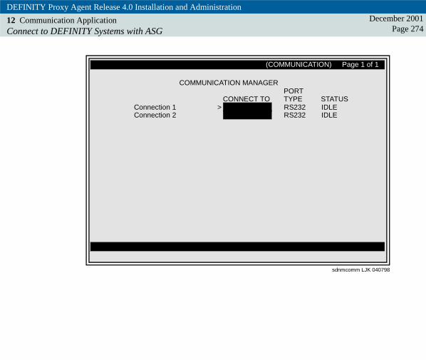
DEFINITY Proxy Agent Release 4.0 Installation and Administration
12 Communication ApplicationConnect to DEFINITY Systems with ASG
December 2001Page 274
COMMUNICATION MANAGER
sdnmcomm LJK 040798
(COMMUNICATION) Page 1 of 1
CONNECT TO STATUSPORTTYPE
Connection 1Connection 2
> RS232RS232
IDLEIDLE

DEFINITY Proxy Agent Release 4.0 Installation and Administration
12 Communication ApplicationConnect to DEFINITY Systems with ASG
December 2001Page 275
2 In the Connection 1 field, execute one of the options (a or b) below:
a If the field is blank, connect the first managed node:
– Press Ctrl-Y to display the Help list
– Select a [managed node] from the list
– Press ENTER
b If the field contains a connection that you want to change, then disconnect the managed node and select a different managed node:
– Press Ctrl-Y to display the Help list
– Select disconnect to drop the current connection
– Press ENTER
– Press Ctrl-Y again
– Select a different [managed node name] for the first connection
– Press ENTER
Result: The system displays the selected node name in the Connection 1 field.
3 Optional. In the Connection 2 field, execute one of the options (a or b) in step 2 above to connect to a second managed node:
Result: The system displays the selected node name in the Connection 2 field.
Note: If users selected a second node name in the Connection 2 field, the system displays the ASG login windows for each of the selected node names. Users must repeat steps 4 through 10 below for the second connection.

DEFINITY Proxy Agent Release 4.0 Installation and Administration
12 Communication ApplicationConnect to DEFINITY Systems with ASG
December 2001Page 276
4 Press Ctrl-E to submit the changes.
Result: The system saves the changes and displays the login window below for the node name selected in the Connection 1 field.
COMMUNICATION MANAGER
sdnmasgl LJK 092399
(COMMUNICATION) Page 1 of 1
CONNECT TOecs1
STATUSPORTTYPE
Connection 1Connection 2
> RS232RS232
IDLEIDLE
Connecting to ecs1
Login:

DEFINITY Proxy Agent Release 4.0 Installation and Administration
12 Communication ApplicationConnect to DEFINITY Systems with ASG
December 2001Page 277
5 In the Login field,
• Type the [managed node login]
• Press ENTER
Result: The system displays the one of two windows depending on whether or not the login and secret key have been saved. Execute one of the options (a or b) listed below:
a To save the login and secret key for new managed nodes, go to step 6.
b To not save the login and secret key for managed nodes, go to step 7.

DEFINITY Proxy Agent Release 4.0 Installation and Administration
12 Communication ApplicationConnect to DEFINITY Systems with ASG
December 2001Page 278
6 Save the Login. If the login and ASG secret key have NOT been saved, the system displays a window with the prompt:
COMMUNICATION MANAGER
sdnmasgs LJK 092399
(COMMUNICATION) Page 1 of 1
CONNECT TOecs1
STATUSPORTTYPE
Connection 1Connection 2
> RS232RS232
IDLEIDLE
Connecting to ecs1
A Login and Access Security Gateway (ASG) Secret Key have NOTbeen saved for SNMP access
Would you like to save Login/ASG Secret Key for SNMP access (y/n)? y
Waiting for connection login - (18 secs. until Connection Timeout)

DEFINITY Proxy Agent Release 4.0 Installation and Administration
12 Communication ApplicationConnect to DEFINITY Systems with ASG
December 2001Page 279
To save the login data, execute the steps (a through d) below:
a At the prompt, type Y (yes) and press ENTER
Result: The system displays a window with the first prompt: Access Security Gateway (ASG) Secret Key:
b At the prompt, type the [secret key] and press ENTER
Result: The system displays a second prompt: Save Login & ASG Secret Key for SNMP access (y/n)?
c At the prompt, type Y (yes) and press ENTER
Result: The system displays the window with the numeric challenge: Challenge: XXX-XXXX
d Go to step 8 to complete the remaining steps in the procedure.

DEFINITY Proxy Agent Release 4.0 Installation and Administration
12 Communication ApplicationConnect to DEFINITY Systems with ASG
December 2001Page 280
7 Do NOT Save the Login. If the login and ASG secret key have previously been saved, the system displays a window with the prompt below:
COMMUNICATION MANAGER
sdnmasgn LJK 092399
(COMMUNICATION) Page 1 of 1
CONNECT TOecs1
STATUSPORTTYPE
Connection 1Connection 2
> RS232RS232
IDLEIDLE
Connecting to ecs1
A Login and Access Security Gateway (ASG) Secret Key have alreadybeen saved for SNMP access
Would you like to re-save Login/ASG Secret Key for SNMP access (y/n)? n
Waiting for connection login - (18 secs. until Connection Timeout)

DEFINITY Proxy Agent Release 4.0 Installation and Administration
12 Communication ApplicationConnect to DEFINITY Systems with ASG
December 2001Page 281
To connect to a managed node without saving the ASG and secret key for an emulation session, execute the steps (a and b) below:
a At the prompt, type N (no) and press ENTER
Result: The system displays the window with the numeric challenge: Challenge: XXX-XXXX
b Go to step 8 to complete the remaining steps in the procedure.
8 ASG Device. Access the hand-held ASG device and enter the required data in the device (secret key, challenge, etc.).
Result: The ASG device displays a 7-digit numeric response.

DEFINITY Proxy Agent Release 4.0 Installation and Administration
12 Communication ApplicationConnect to DEFINITY Systems with ASG
December 2001Page 282
9 Response to the Challenge. In the Response field on the window shown below, execute the steps below:
COMMUNICATION MANAGER
sdnmasgr LJK 092399
(COMMUNICATION) Page 1 of 1
CONNECT TOecs1
STATUSPORTTYPE
Connection 1Connection 2
> RS232RS232
IDLEIDLE
Connecting to ecs1
Login: [node login]Challenge: 871-5423 Product ID: 1000000000
Response:

DEFINITY Proxy Agent Release 4.0 Installation and Administration
12 Communication ApplicationConnect to DEFINITY Systems with ASG
December 2001Page 283
• Type [response number] from the ASG device
• Press ENTER
Result: The system displays the message:Negotiating protocol communication
Then, the system displays the Proxy Agent MAIN MENU that contains the confirmation message:
Connected To [managed node]
10 At the completion of the task, complete the procedure to "Disconnect from Managed Nodes" on page 284.

DEFINITY Proxy Agent Release 4.0 Installation and Administration
12 Communication ApplicationDisconnect from Managed Nodes
December 2001Page 284
Disconnect from Managed NodesComplete the procedure below to manually disconnect the managed nodes.
1 Access the Proxy Agent MAIN MENU.
In the command line,
• Type communication
• Press ENTER
Result: The system displays the COMMUNICATION MANAGER screen.
2 In the Connection 1 field,
• Press Ctrl-Y to select the Help list
• Select disconnect
• Press ENTER
3 Optional. In the Connection 2 field,
• Press Ctrl-Y to select the Help list
• Select disconnect
• Press ENTER
4 Press Ctrl-E to submit the changes.
Result: The system drops the connections and displays the Proxy Agent MAIN MENU.

DEFINITY Proxy Agent Release 4.0 Installation and AdministrationDecember 2001
Page 28513 13Emulation Application
IntroductionThe Emulation application provides communication access to a managed node for real-time administration. procedures to establish an emulation session from the Proxy Agent with one or two managed nodes.
The Emulation application provides direct communication with one or two managed nodes for real-time administration.
Users can access all commands and screens that are available from the G3 management terminal.
For DEFINITY systems, the emulation application adds the following features:
• Reliable communications using a protocol
• Pop-up help
• Direct page selection
• Color
! CAUTION:If the Proxy Agent is active on the switch, you must have multiple communication devices to use emulation cut-through.
See also Refer to Chapter 12, "Communication Application" for procedures to connect two managed nodes before an emulation session and to disconnect the two managed nodes at the end of a session.

DEFINITY Proxy Agent Release 4.0 Installation and Administration
13 Emulation ApplicationReview the Emulation Screen
December 2001Page 286
Review the Emulation ScreenThe following figure shows the two commands available on the EMULATION screen:
Figure 31. Emulation screen
Please select one of the following:
Enter ’quit’ to exit the program
enter command:>
sdnmemu LJK 040798
(EMULATION)
connect quit

DEFINITY Proxy Agent Release 4.0 Installation and Administration
13 Emulation ApplicationConduct an Emulation Session
December 2001Page 287
Conduct an Emulation Session The Emulation application allows users to establish a direct connection with one managed node during an emulation session.
Users do not need to connect a managed node on the COMMUNICATION MANAGER screen before they begin the emulation session with one managed node.
To connect to two managed nodes during an emulation session, refer to the "Connect to Two Managed Nodes" on page 290.
The commands that are available on the G3 management terminal are also available on the Proxy Agent emulation application.

DEFINITY Proxy Agent Release 4.0 Installation and Administration
13 Emulation ApplicationConnect to One Managed Node
December 2001Page 288
Connect to One Managed NodeComplete the following procedure to establish an emulation session with one managed node.
1 Access the Proxy Agent MAIN MENU.
In the command line,
• Type emulation
• Press ENTER
Result: The system accesses the EMULATION application.
2 In the command line,
• Type connect [managed node]
• Press ENTER
Result: The system displays one (a or b) of the following results:
a If the managed node is not connected, then the system displays the login window. Execute the steps 3 and 4 to log in.
b If the managed node is connected, then the system displays the MAIN MENU for the managed node. Go to step 5.
3 In the Login field,
• Type the [managed node login]
• Press ENTER

DEFINITY Proxy Agent Release 4.0 Installation and Administration
13 Emulation ApplicationConnect to One Managed Node
December 2001Page 289
4 In the Password field,
• Type the [managed node password]
• Press ENTER
Result: The system displays the prompt:Save Login/Password for SNMP access (y/n)? n
5 Press ENTER to select no.
Result: The system displays the message:Negotiating protocol communication
Then, displays the MAIN MENU for the managed node.
6 Conduct an administration session on the managed node. The commands that you can normally use with the login you selected will be available to you during this session.
7 To end the emulation session,
• Type quit
• Press ENTER
Result: The system exits the Emulation screen. Then, the system displays the Proxy Agent MAIN MENU.

DEFINITY Proxy Agent Release 4.0 Installation and Administration
13 Emulation ApplicationConnect to Two Managed Nodes
December 2001Page 290
Connect to Two Managed NodesTo conduct an emulation session with two connections, complete the following procedures:
• Access the COMMUNICATION MANAGER screen to connect two managed nodes. Do not save the login data.
• Access the EMULATION screen to conduct the administration session with both managed nodes.
• Access the COMMUNICATION MANAGER to disconnect the two managed nodes.
Procedure Complete the following procedure to establish two connections for an emulation session.
1 Access the Proxy Agent MAIN MENU. In the command line,
• Type communication
• Press ENTER
Result: The system displays the COMMUNICATION MANAGER screen.
2 In the connection fields, connect two managed nodes for the emulation session. Do not save the login data. Refer to the appropriate procedure:
• "Connect to Managed Nodes" on page 266
• "Connect to DEFINITY Systems with ASG" on page 272
Result: The system saves the data and displays the Proxy Agent MAIN MENU.

DEFINITY Proxy Agent Release 4.0 Installation and Administration
13 Emulation ApplicationConnect to Two Managed Nodes
December 2001Page 291
3 In the command line on the Proxy Agent MAIN MENU,
• Type emulation
• Press ENTER
Result: The system displays the EMULATION menu.
4 To establish the connection with the first managed node,
• Type connect [managed node]
• Press ENTER
Result: The system displays the system MAIN MENU for the first managed node.
5 Conduct an administration session on the first managed node. The commands that you can normally use with the login you selected will be available to you during this session.
6 To end the emulation session with the first managed node,
• Type quit
• Press ENTER
Result: The system exits the emulation session with the first managed node. Then, displays the EMULATION menu.
7 To establish the connection with the second managed node,
• Type connect [managed node]
• Press ENTER
Result: The system displays the system MAIN MENU for the second managed node.
DEFINITY Proxy Agent Release 4.0 Installation and Administration
13 Emulation ApplicationConnect to Two Managed Nodes
December 2001Page 292
8 Conduct an administration session on the second managed node.All G3 switch commands are available during the emulation session.
9 To end the emulation session with the second managed node,
• Type quit
• Press ENTER
Result: The system exits the emulation session with the second managed node. Then, displays the EMULATION menu
Note: Users can move back and forth between the connections from the EMULATION menu.
10 To end the emulation session with both connections,
• Type quit
• Press ENTER
Result: The system exits the EMULATION menu. Then, the system displays the Proxy Agent MAIN MENU.
11 In the command line on the Proxy Agent MAIN MENU,
• Type communication
• Press ENTER
Result: The system displays the COMMUNICATION MANAGER screen.
12 On the COMMUNICATION MANAGER screen, disconnect the two managed nodes. Refer to "Disconnect from Managed Nodes" on page 284.

DEFINITY Proxy Agent Release 4.0 Installation and AdministrationDecember 2001
Page 29314 14Configuration Application
IntroductionUse the Configuration application to administer the system-wide default parameters for the communication devices and configuration options for the monitor and screen elements. procedures to administer two configuration screens:
• The CHANGE HARDWARE screen contains the software versions for UnixWare and Proxy Agent and the system-wide default parameters for the serial ports.
The CHANGE USER-INTERFACE screen contains the configuration options for the monitoThe I/O Setup application, which is accessible from the UnixWare desktop, allows system administrators (root users) to edit the Devices file and the Dialers file. This is not part of DEFINITY Proxy Agent.
• Chapter 15, "I/O Setup Application" contains the default dial strings and the procedures to edit the Devices and the Dialers files.r and screen elements.
The purpose of the Configuration application is to administer the system-wide, default parameters on the two configuration screens that are described below.
Change Hardware screen
The CHANGE HARDWARE screen contains two types of information:
• Software release and versions of the UNIX operating system and the Proxy Agent that are currently installed on the Proxy Agent computer
• Default parameters for the serial ports

DEFINITY Proxy Agent Release 4.0 Installation and Administration
14 Configuration ApplicationIntroduction
December 2001Page 294
Change User-Interface screens
The CHANGE USER-INTERFACE screens contains four pages of configuration and color options.
Page 1 contains the configuration options to:
• Set the color options on the monitor
• Turn on or turn off the audible beep tone
Typically, the configuration options on page 1 are the only options that users may want to change.
Pages 2 through 4 contain the options to customize the colors for the elements listed below:
• Screen elements
• Activity Area elements
• Popup Display Window elements

DEFINITY Proxy Agent Release 4.0 Installation and Administration
14 Configuration ApplicationIntroduction
December 2001Page 295
Installation process
During the installation process, the installation script updates the software versions on the CHANGE HARDWARE screen.
The Configuration application contains the system-wide, default parameters for both of the CHANGE HARDWARE screen and the CHANGE USER_INTERFACE screen.
Generally, users will not need to change the default settings on either of the Configuration screens.

DEFINITY Proxy Agent Release 4.0 Installation and Administration
14 Configuration ApplicationAdminister the Change Hardware Screen
December 2001Page 296
Administer the Change Hardware ScreenThe CHANGE HARDWARE screen contains two types of information:
• Software versions for the UNIX operating system and the Proxy Agent software that are currently installed on the Proxy Agent computer
• Default parameters for the serial ports
Avaya recommends that users do not change the default settings for the serial ports on the CHANGE HARDWARE screen. These settings work well with most communication devices.
However, users can change the parameters for individual managed nodes on the page B of the MANAGED NODES screen. The new settings will override the system-wide parameters and become the custom settings for the individual managed node.
PA001 form The Managed Nodes section of the PA001 form should contain the speed setting for serial port that the Proxy Agent uses to connect to individual managed nodes.

DEFINITY Proxy Agent Release 4.0 Installation and Administration
14 Configuration ApplicationReview the Change Hardware Screen
December 2001Page 297
Review the Change Hardware Screen In the figure below, the “xx” in the Proxy Agent Version field refers to the load number of the software, which may vary for the current release.
Figure 32. Change Hardware screen
CHANGE HARDWARE
sdnmhard LJK 062901
(CONFIGURATION)change hardware Page 1 of 1
SOFTWARE VERSIONS
SERIAL PORT DEFAULT PARAMETERS
UNIX Release:UNIX Version:
Proxy Agent Version:
Speed:Stop Bits:
Flow Control?Parity:
Character Size:
4.2MP2.1.3
4.0.X.yyy
>96001nnone8

DEFINITY Proxy Agent Release 4.0 Installation and Administration
14 Configuration ApplicationReview the Change Hardware Screen
December 2001Page 298
Field descriptions The table below contains descriptions of the fields on the CHANGE HARDWARE screen. The screen contains the two sections listed below:
• Software Versions (view-only)
• Serial Port Default Parameters
Table 26. Change Hardware screen
Field Description
SOFTWARE VERSION (view-only)
UNIX Release Identifies the release number of the UnixWare operating system that is currently installed on the Proxy Agent computer.
This is a view-only field.
UNIX Version Identifies the version number of the UnixWare operating system that is currently installed on the Proxy Agent computer.
This is a view-only field.
Proxy Agent Version Identifies the version number of the Proxy Agent software that is currently installed on the Proxy Agent computer.
This is a view-only field.
(1 of 3)

DEFINITY Proxy Agent Release 4.0 Installation and Administration
14 Configuration ApplicationReview the Change Hardware Screen
December 2001Page 299
SERIAL PORT DEFAULT PARAMETERS
Speed Sets the baud rate for the modem that connects the Proxy Agent to the managed node.
The HELP list (Ctrl-Y) contains the valid options for this field:
9600 (default)
4800
2400
1200
Stop Bits Sets the stop bit parameter on the modem.
The HELP list (Ctrl-Y) contains the valid options for this field:
1 (default)
2
Table 26. Change Hardware screen
Field Description
(2 of 3)

DEFINITY Proxy Agent Release 4.0 Installation and Administration
14 Configuration ApplicationReview the Change Hardware Screen
December 2001Page 300
Flow Control Turns-off or turns-on the flow control parameter on the modem.
The HELP list (Ctrl-Y) contains the valid options for this field:
n (no) (default) -- Turn off
y (yes) -- Turn on
Parity Sets the parity parameter on the modem.
The HELP list (Ctrl-Y) contains the valid options for this field:
none (default)
odd
even
Character Size Sets the character size parameter on the modem.
The HELP list (Ctrl-Y) contains the valid options for this field:
8 (default)
7
Table 26. Change Hardware screen
Field Description
(3 of 3)

DEFINITY Proxy Agent Release 4.0 Installation and Administration
14 Configuration ApplicationAdminister the Change Hardware Options
December 2001Page 301
Administer the Change Hardware OptionsComplete the procedure below to access the CHANGE HARDWARE screen.
Generally, users will not change the system-wide, default parameters for the serial port on the CHANGE HARDWARE screen.
Note: Users can make changes to the parameters for individual managed nodes on page B of the MANAGED NODES screen. The changes made on the MANAGED NODES will override the system-wide parameters on the CHANGE HARDWARE screen.
Procedure 1 Access the Proxy Agent MAIN MENU. In the command line,
• Type configuration
• Press ENTER
Result: The system accesses the Configuration application. Then, displays a blank command line on the Proxy Agent MAIN MENU.
2 In the command line on the Proxy Agent MAIN MENU:
• Type change hardware
• Press ENTER
Result: The system displays the CHANGE HARDWARE screen.
3 In the SOFTWARE VERSION column, verify the release numbers for the UnixWare and the Proxy Agent software. The fields are view-only. Users cannot change the data.

DEFINITY Proxy Agent Release 4.0 Installation and Administration
14 Configuration ApplicationAdminister the Change Hardware Options
December 2001Page 302
4 The data in the SERIAL PORT DEFAULT PARAMETERS fields contain the system-wide, default parameters shown below:
Speed: 9600
Stop Bits: 1
Flow Control: n (no)
Parity: none
Character Size: 8
To change the default system parameters, which is NOT recommended:
• Press Ctrl-Y in each field to display the Help list
• Select a new value from the list
• Press ENTER to change the value
5 Execute one of the options (a or b) below:
a If users made any changes, press Ctrl-E to save the changes and exit the CHANGE HARDWARE screen.
b If users do not make any changes, press Ctrl-X to exit the CHANGE HARDWARE screen.
Result: The system exits the screen and displays the Proxy Agent MAIN MENU.

DEFINITY Proxy Agent Release 4.0 Installation and Administration
14 Configuration ApplicationAdminister the Change User-Interface Screen
December 2001Page 303
Administer the Change User-Interface ScreenThe CHANGE USER-INTERFACE screen contains four (4) pages of configuration options.
Page 1 contains the configuration options to:
• Set the color options of the monitor
• Turn-on or turn-off the audible beep tone
Pages 2 through 4 contain the fields to customize the colors of the elements listed below:
• Screen elements on page 2
• Activity Area elements on page 3
• Popup Display Window elements on page 4
Users can experiment with various color combinations and immediately view the results of your changes in the sample screens that appears on pages 2 through 4.

DEFINITY Proxy Agent Release 4.0 Installation and Administration
14 Configuration ApplicationReview the Change User-Interface Screen
December 2001Page 304
Review the Change User-Interface ScreenThe figures in this section show default settings on the four pages of the CHANGE USER-INTERFACE screens.
Page 1 The figure below shows the configuration options on page 1 of the CHANGE USER-INTERFACE screens.
Figure 33. Page 1, Configuration Options
CHANGE USER-INTERFACE
sdnmusr1 LJK 040798
(CONFIGURATION)change user-interface Page 1 of 4
CONFIGURATION OPTIONSColor Option:
Audible Beep Tone?>monochrome
y

DEFINITY Proxy Agent Release 4.0 Installation and Administration
14 Configuration ApplicationReview the Change User-Interface Screen
December 2001Page 305
Page 1 field descriptions
The table below contains the field descriptions for configuration options on page 1 of the CHANGE USER-INTERFACE screens.
Table 27. Configuration options
Field Description
CONFIGURATION OPTIONS (page 1)
Color Option Sets the colors for the monitor.
The Help list (Ctrl-y) contains the valid options for the field:
default -- for color monitors
monochrome -- default for black-and-white monitors
customize -- change color of screen elements (see pages 2 through 4 below)
Audible Beep Tone? Sets the beep tone to ON or OFF.
The Help list (Ctrl-y) contains the valid options for the field:
y (yes) -- Turns ON the beep tone (default)
n (n) -- Turns OFF the beep tone

DEFINITY Proxy Agent Release 4.0 Installation and Administration
14 Configuration ApplicationReview the Change User-Interface Screen
December 2001Page 306
Page 2 The figure below shows the screen element colors on page 2 of the CHANGE USER-INTERFACE screens.
Figure 34. Page 2, Screen Element Colors
CHANGE USER-INTERFACE
SAMPLE SCREEN
Background
sdnmusr2 LJK 040798
(CONFIGURATION)change user-interface Page 2 of 4
SCREEN ELEMENT COLORSBackground:
Bars:Command Line:
Function Buttons:
> lack
White on Black
BBlack on White
Black on White
Bars
Bars
Ctrl-l to select funct Ctrl-r to repeatCommand line

DEFINITY Proxy Agent Release 4.0 Installation and Administration
14 Configuration ApplicationReview the Change User-Interface Screen
December 2001Page 307
Page 3 The figure below shows the activity area element colors on page 3 of the CHANGE USER-INTERFACE screens.
Figure 35. Page 3, Activity Area Element Colors
CHANGE USER-INTERFACE
SAMPLE SCREEN
Text(Screen Title)
Warning Display Field Error Display Field
Field Label:Display Field Label:
Field DataDisplay Field DataTag only field
sdnmusr3 LJK 040798
(CONFIGURATION)change user-interface Page 3 of 4
ACTIVITY AREA ELEMENT COLORSText:
Field Label:Field Data:
Tag-only Field:Display-only Field:
Warning Display-only Field:Error Display-only Field:
> hite on BlackWhite on Black
White on BlackWhite on Black
W
Black on White
Black on WhiteBlack on White
Bars
Bars
Ctrl-l to select funct Ctrl-r to repeatCommand line

DEFINITY Proxy Agent Release 4.0 Installation and Administration
14 Configuration ApplicationReview the Change User-Interface Screen
December 2001Page 308
Page 4 The figure below shows the popup display window element colors on page 4 of the CHANGE USER-INTERFACE screen.
Figure 36. Page 4, Popup Display Window Element Colors
CHANGE USER-INTERFACE
sdnmusr4 LJK 040798
(CONFIGURATION)change user-interface Page 4 of 4
POPUP DISPLAY WINDOW ELEMENT COLORSBorder and Background:
Field Label:Field Data:
Text:Highlight:
Tag-only Field:Display-only Field:Activity Message:
> hite on BlackWhite on Black
White on Black
White on BlackWhite on BlackWhite on Black
W
Black on White
Black on White
> hite on BlackWhite on Black
White on Black
White on BlackWhite on BlackWhite on Black
W
Black on White
Black on White
Text(Heading) Border/BackgroundField Label:
Display Field Label:Field DataDisplay Field DataTag only field
SAMPLEWINDOWS
Activity messages appear here
element
elementhighlight
1
32

DEFINITY Proxy Agent Release 4.0 Installation and Administration
14 Configuration ApplicationAdminister the Change User-Interface Options
December 2001Page 309
Administer the Change User-Interface OptionsComplete the procedure below to change the system-wide, default parameters for the configuration and color options.
Note: For color monitors, users must set the TERM variable to color or default so that Proxy Agent screens will be in color.
1 Access the Proxy Agent MAIN MENU. In the command line:
• Type configuration
• Press ENTER
Result: The system accesses the Configuration application. Then, displays a blank command line on the Proxy Agent MAIN MENU.
2 In the command line on the Proxy Agent MAIN MENU:
• Type, change user-interface
• Press ENTER
Result: The system displays page 1 of the CHANGE USER-INTERFACE screen.
3 In the Color Option field on page 1,
• Press Ctrl-Y to display the Help list
• Select one of the options below:
default (for color monitors)
monochrome (default for black- and-white monitors)
customize
• Press ENTER to change the option

DEFINITY Proxy Agent Release 4.0 Installation and Administration
14 Configuration ApplicationAdminister the Change User-Interface Options
December 2001Page 310
4 In the Audible Beep Tone? field on page 1,
• Press Ctrl-Y to display the Help list.
• Select one of the options below:
– Y (yes) to turn-on the beep tone (default)
– N (no) to turn-off the beep tone
• Press ENTER to change the option
5 Optional. Complete the steps below to customize the colors of the screen elements on pages 2 through 4,
• Press Ctrl-Y to in each field to display the Help list
• Select an option
• Press ENTER to change the option
• Press Ctrl-D to access the next page
6 Execute one of the options (a or b) below:
a If users made any changes, press Ctrl-E to save the changes and exit the CHANGE USER-INTERFACE screen.
b If users do not want to make any changes, press Ctrl-X to exit the CHANGE USER- INTERFACE screen.
Result: The system exits the screen and displays the Proxy Agent MAIN MENU.

DEFINITY Proxy Agent Release 4.0 Installation and AdministrationDecember 2001
Page 31115 15I/O Setup Application
IntroductionThe I/O Setup application provides direct access to the Devices file and the Dialers file:
• The Devices file contains the tty port settings for the communication devices that connect the Proxy Agent to the managed nodes.
• The Dialers file contains the device name and dial strings that the Proxy Agent uses to dial into the managed node.
! CAUTION:Avaya recommends that users do not change the settings in the Devices file unless their business needs require modification of the file. Only the system administrator or root user should edit the Devices and Dialers files.
Installation process
During the installation process, the installation script updates the Devices file and the Dialers file with default parameters for this release.

DEFINITY Proxy Agent Release 4.0 Installation and Administration
15 I/O Setup ApplicationAccess the IO_Setup Folder
December 2001Page 312
Access the IO_Setup FolderThe DEFINITY Proxy Agent installation process configures and adds the Devices file and the Dialers file. Generally, there is no need to access these files. However, if necessary, system administrators and root users can edit the Devices file and the Dialers file from the IO_Setup folder on the UnixWare Desktop.
Root users can also edit these files from the UNIX shell.
! CAUTION:Avaya recommends that users do not change the settings in the Devices file unless their business needs require modification of the file. Only the system administrator or root user should edit the Devices and Dialers files.
Procedure Complete the procedure below to access IO_Setup folder on the Desktop.
1 Log in as a root user and access the UnixWare Desktop.
Result: The system displays the Desktop.
2 Click the DEFINITY_Proxy icon.
Result: The system displays the DEFINITY_Proxy folder.

DEFINITY Proxy Agent Release 4.0 Installation and Administration
15 I/O Setup ApplicationAccess the IO_Setup Folder
December 2001Page 313

DEFINITY Proxy Agent Release 4.0 Installation and Administration
15 I/O Setup ApplicationAccess the IO_Setup Folder
December 2001Page 314
3 Click the IO_Setup icon.
Result: The system IO_Setup folder below:
Folder: IO_Setup
E d it_D e v ice s E d it_D ia le rs
s d n m s e tu K L C 0 3
F ile E d it V iew G o To H e lp

DEFINITY Proxy Agent Release 4.0 Installation and Administration
15 I/O Setup ApplicationAccess the IO_Setup Folder
December 2001Page 315
4 Double-click either the Edit_Devices icon or the Edit_Dialers icon.
Result: The system displays a window and prompt for your root password.
! CAUTION:Avaya recommends that users do not change the settings in the Devices file unless their business needs require modification of the file. Only the system administrator or root user should edit the Devices and Dialers files.
5 At the Password field,
• Enter your [root password]
• Press ENTER
Result: The system displays the selected file.
6 For special instructions to edit the Devices file or the Dialers file, refer to Chapter 15, "I/O Setup Application".
7 To exit file from the Menu Bar, select File > Exit.
Result: The system displays the DEFINITY_Proxy folder.

DEFINITY Proxy Agent Release 4.0 Installation and Administration
15 I/O Setup ApplicationDevices File
December 2001Page 316
Devices File The Devices file contains the updated tty port settings for the communication devices that are described below.
The Avaya-certified alarm receiver devices include the following types:
• AT&T 2224CEO
• AT&T 3710 Dataport
• AT&T 3715 Dataport Express
• U.S. Robotics Sportster 33.6
• US Robotics Sportster 56K
• Paradyne Compusphere 3820
The Avaya-certified alarm sender devices include the following types:
• AT&T 3710 Dataport
• AT&T 3715 Dataport Express
• U.S. Robotics Sportster 33.6
• US Robotics Sportster 56K
Note: Avaya does not certify the AT&T 2224CEO as an alarm sender device for Proxy Agent to forward alarms to INADS.
! CAUTION:Avaya recommends that users do not change the settings in the Devices file unless their business needs require modification of the file.

DEFINITY Proxy Agent Release 4.0 Installation and Administration
15 I/O Setup ApplicationDialers File
December 2001Page 317
Dialers File This section contains the contents of the Dialers file and the procedure to edit the dial strings.
Devices and Dial StringsThe information below is an excerpt from the Dialers file that contains the list of the Avaya-certified devices and the dial string for each device function.
############################################################
Start DG3PA DIAL STRINGS: (DONT MODIFY THIS LINE)
This section is maintained by the DEFINITY G3 Proxy Agent Installation scripts. Any changes manually made to this section may be lost on upgrades.
PA prefix is for Proxy Agent switch/ecs access
PAD prefix is for Proxy Agent switch/ecs access with Terminal Servers that fail to drop DTR correctly during a disconnect
AS prefix is for Proxy Agent Alarm Sending/Forwarding
AR prefix is for Proxy Agent Alarm Reception modem options
RM prefix is for Avaya TSC/ITAC Remote Maintenance Modem options

DEFINITY Proxy Agent Release 4.0 Installation and AdministrationDecember 2001
Page 31816 16Maintenance and Troubleshooting
Introductioncontains utilities and logs to allow the system administrator to maintain the Proxy Agent and troubleshoot problems with alarms, traps, and system errors.
The chapter also contains an example of a Test Trap script to test an event configuration on the Network Management System (NMS).
The Proxy Agent contains several maintenance and troubleshooting options that only the system administrator or root user should execute to manage the Proxy Agent.
These options include tasks listed below:
• Add new devices to the Proxy Agent after the Proxy Agent has been installed
• Change settings for SNMP access after the Proxy Agent has been installed
• View alarm and error logs to troubleshoot the receiving and forwarding of alarms
• Use the alarm testing tools to simulate alarm and trap reception on the Proxy Agent and test the event configuration on the Network Management System (NMS)

DEFINITY Proxy Agent Release 4.0 Installation and Administration
16 Maintenance and TroubleshootingAdd New Devices
December 2001Page 319
Add New DevicesThe system administrator or root user can add new communications devices to the Proxy Agent from the /usr/bin/dpa_portadm file.
System administrators must access the file and respond to the prompts. The prompts are identical to the prompts in the installation script for the function and the device type.
For more information, refer to the sections listed below:
• "Function Prompt" on page 91.
• "Device Type Prompt" on page 93.
• "Serial I/O Subsystem" on page 95.
• "Upgrading from DPA 3.0 and Later" on page 107.

DEFINITY Proxy Agent Release 4.0 Installation and Administration
16 Maintenance and TroubleshootingChange Settings for SNMP Access
December 2001Page 320
Change Settings for SNMP AccessThe system administrator or root user must reinstall the Proxy Agent in order to change settings for SNMP access.
Refer to the procedure to "Upgrading from DPA 3.0 and Later" on page 107. It is not necessary to remove the Proxy Agent.
At the installation prompts listed below, change the current setting for:
• SNMP Polling
• SNMP Traps, if SNMP Polling is disabled
• SNMP Set Capability
For more information about the SNMP prompts, refer to the sections below:
• "SNMP Polling Prompt" on page 90
• "SNMP Traps Prompt" on page 90
• "SNMP Set Capability Prompt" on page 91
TSC service The Technical Services Center (TSC) can change the settings for the SNMP access prompts without reinstalling the Proxy Agent.
The TSC will bill the customer for this service on a time and materials basis.

DEFINITY Proxy Agent Release 4.0 Installation and Administration
16 Maintenance and TroubleshootingView Alarm and Error Logs
December 2001Page 321
View Alarm and Error LogsThe Proxy Agent maintains a number of alarm and error logs in the agent directory. System administrators can view the logs to troubleshoot problems with receiving and forwarding alarms.
To access the logs, edit the directories in the table below.
Table 28. Alarm and error logs
Log Directory
Event log for alarm receiver device
/usr/g3-ma/agent/logs/alarmlog
Error log for alarm receiver device
/usr/g3-ma/agent/logs/errorlog
Alarms scheduled to be sent to INADS or other destinations
/usr/g3-ma/agent/alarms/alrms_rcvd.log
Alarms successfully sent to INADS or other destinations
/usr/g3-ma/agent/alarms/alrms_sent.log
Error log for alarm sender device
/usr/g3-ma/agent/alarms/alarms.log

DEFINITY Proxy Agent Release 4.0 Installation and Administration
16 Maintenance and TroubleshootingUse Alarm Testing Tools
December 2001Page 322
Use Alarm Testing ToolsThe Proxy Agent contains a set of Trap Test tools. System administrators can use these tools to:
• Simulate the alarm reception on the Proxy Agent and
• Test the trap reception and event configuration on the Network Management System (NMS)
The Proxy Agent contains a script for each product type. All scripts reside in the /usr/g3-ma/bin directory.
Trap Test scripts The table below contains the command and function for the trap tests scripts:
Table 29. Trap Test Scripts
Command Function
TrapTest DEFINITY and MCU traps
CMSTrapTest Call Management System (CMS) traps
ADXTrapTest DEFINITY AUDIX traps
IADTrapTest Intuity AUDIX traps
INTTrapTest Intuity Interchange traps
CVSTrapTest CONVERSANT traps

DEFINITY Proxy Agent Release 4.0 Installation and Administration
16 Maintenance and TroubleshootingUse Alarm Testing Tools
December 2001Page 323
Procedure The procedure below uses the DEFINITY TrapTest tool as an example of the format for the alarm testing tools. For other products, the script for the TrapTest tool is slightly different.
Note: For the tools to work, the Proxy Agent must be running and the ALARM DEVICES and MANAGED NODES screens must be properly administered.
1 At the UNIX shell, log in to the root (/) directory.
2 Access a test script. The steps below show an example of a TrapTest script:
• Type /usr/g3-ma/bin/TrapTest
• Press ENTER
Result: The system opens the file and displays the script for the selected trap test, as shown in the example below. The fields may contain the data from the previous test.
DEFINITY Proxy Agent Alarm Trap Test Tool
Current DEFINITY Node Name: NewYorkCurrent DEFINITY Alarm ID: 1111111111
0) Alarm Clear Trap [alarmClear:0]2) Major Alarm Trap [alarmMajor:2]3) Minor Alarm Trap [alarmMinor:3]5) Major External Alarm Trap [extalarmMajor:5]6) Minor External Alarm Trap [extalarmMinor:6]7) TSC Dispatch Alarm Trap [alarmDispatch:7]8) TSC Close Alarm Trap [alarmClose:8]9) Restart Notification Trap [alarmRestart:9]
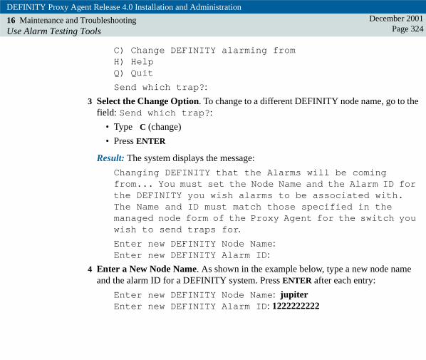
DEFINITY Proxy Agent Release 4.0 Installation and Administration
16 Maintenance and TroubleshootingUse Alarm Testing Tools
December 2001Page 324
C) Change DEFINITY alarming fromH) HelpQ) Quit
Send which trap?:
3 Select the Change Option. To change to a different DEFINITY node name, go to the field: Send which trap?:
• Type C (change)
• Press ENTER
Result: The system displays the message:
Changing DEFINITY that the Alarms will be coming from... You must set the Node Name and the Alarm ID for the DEFINITY you wish alarms to be associated with. The Name and ID must match those specified in the managed node form of the Proxy Agent for the switch you wish to send traps for.
Enter new DEFINITY Node Name: Enter new DEFINITY Alarm ID:
4 Enter a New Node Name. As shown in the example below, type a new node name and the alarm ID for a DEFINITY system. Press ENTER after each entry:
Enter new DEFINITY Node Name: jupiterEnter new DEFINITY Alarm ID: 1222222222

DEFINITY Proxy Agent Release 4.0 Installation and Administration
16 Maintenance and TroubleshootingUse Alarm Testing Tools
December 2001Page 325
Result: The system displays the new node name and alarm ID in the fields and displays the prompt to select a trap test, as shown below.
DEFINITY Proxy Agent Alarm Trap Test Tool
Current DEFINITY Node Name: jupiterCurrent DEFINITY Alarm ID: 1222222222
0) Alarm Clear Trap [alarmClear:0]2) Major Alarm Trap [alarmMajor:2]3) Minor Alarm Trap [alarmMinor:3]5) Major External Alarm Trap [extalarmMajor:5]6) Minor External Alarm Trap [extalarmMinor:6]7) TSC Dispatch Alarm Trap [alarmDispatch:7]8) TSC Close Alarm Trap [alarmClose:8]9) Restart Notification Trap [alarmRestart:9]
C) Change DEFINITY alarming fromH) HelpQ) Quit
Send which trap?:
5 Select a trap option. As shown in the example below, type a number (0-9) to select a trap test and press ENTER.
Send which trap?: 5
Result: The system displays the message and the fields shown in the example in the next step.

DEFINITY Proxy Agent Release 4.0 Installation and Administration
16 Maintenance and TroubleshootingUse Alarm Testing Tools
December 2001Page 326
6 Execute the trap test. Users can enter any data in the in the free-form fields. The system does not validate the fields. As shown in the example below, type data in each field and press ENTER after each entry:
Enter alarm trap information for External trap
MIB oid names are show in brackets
Switch [g3clientExternalName]: jupiterProxy Agent Sequence Number [g3alarmsAlarmNumber]: 0000000012Switch Port Location [g3alarmsPort]: 01C1201On-Board Alarm Flag [g3alarmsOnBrd]: YExternal Device Alt. Name [g3extdevAltName]: ENVUPS1External Device Description [g3extdevDescription]: PROXY AGENT UPSExternal Device ID [g3extdevID]: 2001External Device Building [g3extdevBuilding]: Building 30External Device Address [g3extdevAddress]: 1234 Main St
Result: The system displays the message: Alarm Trap Emulation Successful
Then, the system displays the UNIX prompt.
7 Access the NMS to view the results of the test. Repeat this procedure to execute other trap tests.

DEFINITY Proxy Agent Release 4.0 Installation and Administration
December 2001Page 327Index
A ADUwith moss adaptor, cable connections for 64
analogcable connections for local modems 61
Audible Beep Tone field, on Change User-Interface screen 305
C cable connectionsfor ADU with moss adaptor 64for digital data modules 63for local analog modems 61
Char Size field, on page B of Managed Nodes screen 235Character Size field, on Change Hardware screen 300Connection 1 field, on Communication Manager screen 264custom submap
in Submap Name field on Managed Nodes screen 238
D Default Login screenprocedure to administer login data 218
DEFINITY Network Managementnetwork configuration 44, 65
Dial String field, on pages D and E of Managed Nodes screen 243, 244Dialing Order field, on pages D and E of Managed Nodes screen 242digital data module
cable connections 63
F Filter Setprocedure to add new 203
Flow Cntrl field, on page B of Managed Nodes screen 235Flow Control field, on Change Hardware screen 300

DEFINITY Proxy Agent Release 4.0 Installation and Administration
Index December 2001Page 328
fraudAvaya Disclaimer 21Intervention 21password 20risk 21
I IP connectivity 255
L Lucent Worldwide Services (LWS)design and build custom systems 12
M Managed Nodes screenfield descriptions for page F 246
N network security 20Node Name field
on page C of Managed Nodes screen 237on pages D and E of Managed Nodes screen 241
P Parity fieldon Change Hardware screen 300on page B of Managed Nodes screen 235
Passwordssecurity alert 20
Port Type field, on Communication Manager screen 265Proxy Agent
log in security 46new features 42
Proxy Agent Version field, on Change Hardware screen 298
Q quit command, on Proxy Admin screen 148

DEFINITY Proxy Agent Release 4.0 Installation and Administration
Index December 2001Page 329
R referencesintroduction 14vendor web sites 18
S Sales and Design Support Center (SDSC)design connectivity and network systems 12
securityAvaya disclaimer 21customer responsibility 20for networks 20password use 20Proxy Agent access 46SNMP authentication 46toll fraud intervention 21toll fraud risk 21
SNMPsecurity authentication 46
Speed fieldon Change Hardware screen 299
start command, on Proxy Admin screen 148State field
on page C of Managed Nodes screen 238Status field, on Communication Manager screen 265Stop Bits field
on Change Hardware screen 299stop command, on Proxy Admin screen 148Submap Name field
on page C of Managed Nodes screen 238Submap Type field
on page C of Managed Nodes screen 237
DEFINITY Proxy Agent Release 4.0 Installation and Administration
Index December 2001Page 330
T Technical Services Center (TSC)time and material charges 13
toll fraudAvaya disclaimer 21password use 20risk 21
U UNIX Release field, on Change Hardware screen 298UNIX Version field, on Change Hardware screen 298