10818
TRANSCRIPT

Engineering Processes for Decentralized Factory Automation Systems 1
Engineering Processes for Decentralized Factory Automation Systems
Thomas Wagner, Carolin Haußner, Jürgen Elger, Ulrich Löwen and Arndt Lüder
x
Engineering Processes for Decentralized Factory Automation Systems
Thomas Wagner1, Carolin Haußner1, Jürgen Elger1,
Ulrich Löwen1 and Arndt Lüder2 1Siemens AG, Corporate Technology, Department of Systems Engineering, Germany
2Otto-von-Guericke-University Magdeburg, Institute for Ergonomics, Manufacturing Systems, and Automation, Center for Distributed Systems, Germany
1. Introduction
The necessity to improve the current automation concepts for cost reduction in factory automation represents a widely discussed problem. Research has developed solutions for this problem area for quite some time based on decentralized automation concepts (e.g., holonic systems, agent systems). For an overview of agent-oriented systems, please refer to (Jennings, 2000; Weiß, 2002); for agent-oriented or holonic automation systems, see (Parunak 1998; Shen et. al, 2006; Barata, 2001; Wagner et. al., 2003). However, industrial companies have shown reluctance concerning a broad application in practice. The reasons reside mainly in lacking engineering methods for systematic imple-mentation in industrial businesses (Hall et. al., 2005) and lacking reliable evaluation of the consequences for application domains over the entire life cycle (Lu & Jafari, 2007). The main goal for the development of decentralized automation concepts and systems is to achieve flexibility in factory automation systems, driven by ever more rapidly changing production conditions, such as order variations, changing products, load variations, or plug&produce capabilities of machines (ElMaraghy, 2005; Wagner & Goehner, 2006). Hence, the value promised by decentralized automation concepts mainly resides in the improvement of operative parameters of a plant, for instance, through more flexibility of usage, higher efficiency, or availability. Such parameters were evaluated based on proto-types, as well as by means of simulation, and were verified with a relatively good validity (Sundermeyer & Bussmann, 2001; Thramboulidis, 2008). However, the costs for introducing and applying decentralized automation concepts and systems – in terms of total cost of ownership (TCO) – have not been properly investigated yet, neither in science nor in industrial application. The reason is that we know much about the operation phase behaviour of production facilities using decentralized automa-tion systems, but there exists hardly any explanation of the impact, in terms of benefits and risks, on the entire industrial life cycle (Habib 2007). In addition to operating costs, the second most important aspect of TCO lies in the activities and processes for engineer-ing (design, realization, and commissioning) of production facilities. The related cost po-tential is certainly significant. In 2005, automotive manufacturers identified the portion of
1
www.intechopen.com

Factory Automation2
the cost for engineering tasks in automotive manufacturing to be 20 to 25% of the total investment for the production line and 55% for the control system – with an upward trend (Alonso Garcia & Drath, 2007). Hence, the requirements for engineering of such facilities must be considered (Achatz & Loewen, 2005). The main objective here is to identify the impact of automation concepts on engineering activities, to create suitable and effective engineering methods for decentralized automation, and to render them applicable for industrial applications. Based on our industrial project experience with production lines in the automotive indus-try and with intralogistics systems such as automatic warehouses, and our experience in decentralized automation systems from two research projects PABADIS'PROMISE (PABADIS'PROMISE, 2008) and “Internet of Things” (Internet of Things, 2009), we de-rived engineering methods and processes for two use cases: Engineering of decentralized production line control and Engineering of decentralized material flow control For these two use cases, we will also elaborate the consequences for the engineering con-tributors, like suppliers or system integrators, as well as the evolving benefits and risks. For this purpose, we apply a systematic evaluation methodology that we have developed in earlier projects (Wagner et. al., 2008). The evaluation is performed through qualitative comparison of the different engineering processes. Based on the evaluation results, we will also present an iterative concept for a stepwise introduction of and migration to de-centralized automation systems in industrial applications without disruptive technology changes.
2. Basic Approach of (Intelligent) Decentralized Automation
The factory automation is structured hierarchically in form of an “automation pyramid,” in which each level performs special automation functions. Individual automation devic-es/systems, such as field devices, PLC, HMI, and control systems, are specifically attri-buted to individual levels (Table 1). Data generated in industrial production are strictly attributed to the different levels, transferred via interfaces, and aggregated or abstracted. Level acc. IEC62264
Label Typical Systems Tasks (excerpt)
4 Enterprise level
Enterprise Resource Planning Systems
Rough production planning Order processing, logistics
3 Production level
Manufacturing Execu-tion, or Warehouse Management Systems
Order management: detailed planning, control, and monitoring of production or material flow
Management of plant information, reports, alarms Management of resources, personnel, and quality Maintenance and material inventory management
2 Process control level
Process control, HMI, and SCADA systems
Superordinate process control and monitoring (for continuous, batch, or discrete processes)
Operation, monitoring, measurement archiving Recipe administration and implementation
1 Automa-tion level
PLCs, motion control-lers
Control, Monitoring and diagnostics for the equip-ment and machines to be automated
Field level I/O-modules, field devices, field bus
Collection and processing of information from the technological process through sensors
Active process intervention through actuators Table 1. Automation Levels and Systems
Initially, approaches for the decentralization of systems within factory automation oc-curred primarily at the hardware level based on PLC and field bus systems with process oriented automation functions (e.g., systems for decentralized periphery such as SIMATIC ET 200, or for DCS, such as PCS7). An essential objective here was the reduction of cabling and thus hardware cost. The consistent further development of these concepts led to intel-ligent field devices and the distribution of process oriented process control functions. Such decentralization, however, applied mainly to Level 1 Systems with process-oriented functions. In the meantime, numerous research projects develop decentralized concepts that include also the higher levels of the classic automation pyramid, such as production control systems and material flow computers reaching level 2 & 3 systems. The basic idea of these approaches is to modularize “central” process control tasks and to decentralize them to basic control unit types: Independent functional automation units representing and controlling the resources of
a factory and Independent production process units representing and controlling the processed
objects within the factory (e.g., a manufactured workpieces, products or transported goods)
Decentralized process control is achieved by situation-based interaction of controlling units of resources, as well as those of processed objects, resulting in a dynamic online setting for the process. For implementation of such approaches, mainly agent-systems are applied.
3. Use Cases of Decentralized Automation Systems in Factory Automation
There are various reasons for research and development of decentralized automation technologies. However, decentralized automation systems do not have an advantage per se, but must rather be regarded as means to achieve certain benefits and objectives. Ex-amples for the benefits are: Increase of the flexibility and improvement of the adaptability of the automation system, Higher efficiency (throughput, use of resources, degree of automation), Reduction of communication effort, Increased robustness and reliability by local troubleshooting, Reduction of complexity for integration of resources/machines, and Faster setup and reconfiguration. The following two applications of decentralized automation were developed in the framework of the research projects PABADIS'PROMISE and Internet of Things. They are representative for approaches in decentralized factory automation and can be found in a similar manner in other approaches (Shen et. al, 2006; Bussmann, 1998; Tönshoff & Woelk, 2001; Hall, 2005).
3.1 Flexible, Decentralized Production Systems Accelerated innovation, shorter product life cycles, and more variants combined with small batch sizes represent new tasks for production automation. In the future, produc-tion plant suppliers must provide the following functionalities in addition to the actual automation:
www.intechopen.com

Engineering Processes for Decentralized Factory Automation Systems 3
the cost for engineering tasks in automotive manufacturing to be 20 to 25% of the total investment for the production line and 55% for the control system – with an upward trend (Alonso Garcia & Drath, 2007). Hence, the requirements for engineering of such facilities must be considered (Achatz & Loewen, 2005). The main objective here is to identify the impact of automation concepts on engineering activities, to create suitable and effective engineering methods for decentralized automation, and to render them applicable for industrial applications. Based on our industrial project experience with production lines in the automotive indus-try and with intralogistics systems such as automatic warehouses, and our experience in decentralized automation systems from two research projects PABADIS'PROMISE (PABADIS'PROMISE, 2008) and “Internet of Things” (Internet of Things, 2009), we de-rived engineering methods and processes for two use cases: Engineering of decentralized production line control and Engineering of decentralized material flow control For these two use cases, we will also elaborate the consequences for the engineering con-tributors, like suppliers or system integrators, as well as the evolving benefits and risks. For this purpose, we apply a systematic evaluation methodology that we have developed in earlier projects (Wagner et. al., 2008). The evaluation is performed through qualitative comparison of the different engineering processes. Based on the evaluation results, we will also present an iterative concept for a stepwise introduction of and migration to de-centralized automation systems in industrial applications without disruptive technology changes.
2. Basic Approach of (Intelligent) Decentralized Automation
The factory automation is structured hierarchically in form of an “automation pyramid,” in which each level performs special automation functions. Individual automation devic-es/systems, such as field devices, PLC, HMI, and control systems, are specifically attri-buted to individual levels (Table 1). Data generated in industrial production are strictly attributed to the different levels, transferred via interfaces, and aggregated or abstracted. Level acc. IEC62264
Label Typical Systems Tasks (excerpt)
4 Enterprise level
Enterprise Resource Planning Systems
Rough production planning Order processing, logistics
3 Production level
Manufacturing Execu-tion, or Warehouse Management Systems
Order management: detailed planning, control, and monitoring of production or material flow
Management of plant information, reports, alarms Management of resources, personnel, and quality Maintenance and material inventory management
2 Process control level
Process control, HMI, and SCADA systems
Superordinate process control and monitoring (for continuous, batch, or discrete processes)
Operation, monitoring, measurement archiving Recipe administration and implementation
1 Automa-tion level
PLCs, motion control-lers
Control, Monitoring and diagnostics for the equip-ment and machines to be automated
Field level I/O-modules, field devices, field bus
Collection and processing of information from the technological process through sensors
Active process intervention through actuators Table 1. Automation Levels and Systems
Initially, approaches for the decentralization of systems within factory automation oc-curred primarily at the hardware level based on PLC and field bus systems with process oriented automation functions (e.g., systems for decentralized periphery such as SIMATIC ET 200, or for DCS, such as PCS7). An essential objective here was the reduction of cabling and thus hardware cost. The consistent further development of these concepts led to intel-ligent field devices and the distribution of process oriented process control functions. Such decentralization, however, applied mainly to Level 1 Systems with process-oriented functions. In the meantime, numerous research projects develop decentralized concepts that include also the higher levels of the classic automation pyramid, such as production control systems and material flow computers reaching level 2 & 3 systems. The basic idea of these approaches is to modularize “central” process control tasks and to decentralize them to basic control unit types: Independent functional automation units representing and controlling the resources of
a factory and Independent production process units representing and controlling the processed
objects within the factory (e.g., a manufactured workpieces, products or transported goods)
Decentralized process control is achieved by situation-based interaction of controlling units of resources, as well as those of processed objects, resulting in a dynamic online setting for the process. For implementation of such approaches, mainly agent-systems are applied.
3. Use Cases of Decentralized Automation Systems in Factory Automation
There are various reasons for research and development of decentralized automation technologies. However, decentralized automation systems do not have an advantage per se, but must rather be regarded as means to achieve certain benefits and objectives. Ex-amples for the benefits are: Increase of the flexibility and improvement of the adaptability of the automation system, Higher efficiency (throughput, use of resources, degree of automation), Reduction of communication effort, Increased robustness and reliability by local troubleshooting, Reduction of complexity for integration of resources/machines, and Faster setup and reconfiguration. The following two applications of decentralized automation were developed in the framework of the research projects PABADIS'PROMISE and Internet of Things. They are representative for approaches in decentralized factory automation and can be found in a similar manner in other approaches (Shen et. al, 2006; Bussmann, 1998; Tönshoff & Woelk, 2001; Hall, 2005).
3.1 Flexible, Decentralized Production Systems Accelerated innovation, shorter product life cycles, and more variants combined with small batch sizes represent new tasks for production automation. In the future, produc-tion plant suppliers must provide the following functionalities in addition to the actual automation:
www.intechopen.com

Factory Automation4
Production flexibility through individual production planning, and optimization, Vertical integration of information and functions at control, MES, and ERP levels, and Fast reconfiguration and scalable capacity through dynamic resource integration
(“Plug’n’Produce”). In the European research project PABADIS'PROMISE, an architectural basis for flexible and vertically seamless production automation was developed. Key features of the ap-proach are: Product driven definition of control processes instead of machine centered definition, Merging of the previously hierarchically separated tasks of control and MES systems, Decentralization of the automation functions into independent, cooperating units. In this approach, the product to be manufactured represents the set point, while the con-trol system is based on an explicit description of product data and production processes (machine independent working processes and parameters). Machine interfaces are de-scribed accordingly in a behavior-oriented manner. The integrated description model serving as basis represents an expansion of the IEC/ISO 62264 Standard (Diep et. al., 2007). Based on these descriptions, the product-specific, on-the-fly configuration of the specific production processes of the production system and the dynamic integration of additional modules at runtime are implemented by means of software agents and RFID technology. Machines and production orders are represented by a logically and physically decentralized agent network (see Fig. 1), which coordinates the production process dy-namically according to machine functions, degree of utilization, and error status, as well as allows the seamless online access from the ERP level to the field level (Lüder, et al., 2007). Fig. 1 depicts an example of decentralized control of an automotive production line where the approach was prototyped.
AutomationUnit AutomationUnit AutomationUnit
AutomationUnit
AutomationUnit AutomationUnitPhysics
Field controlMachinecontrol
AutomationUnitPhysics
Field controlMachinecontrol
PhysicsField control
Machinecontrol
Communication and interaction
Production order unit
Sequence,ParametersProduct data Status
Product process control
Production flow Fig. 1. Decentralized automotive production line acc. to the PABADIS’PROMISE approach
3.2 Flexible, Decentralized Intralogistics Systems The term intralogistics refers to the logistical flow of goods and data "inside the four walls" of a plant. A typical example of an intralogistics system is an automatic high bay warehouse for storage and retrieval of goods in combination with an automated transport system that moves these goods within the plant. Currently, such systems are designed to fulfill a specialized and more or less static workflow. In the future, there will be a stronger demand to support or quickly adapt to different workflows to increase flexibility and adaptability both in the warehouse and in the transport area. A practical application example is the increasing third-party business in the intralogistics area in which logistics companies perform storage and shipping services for one or more
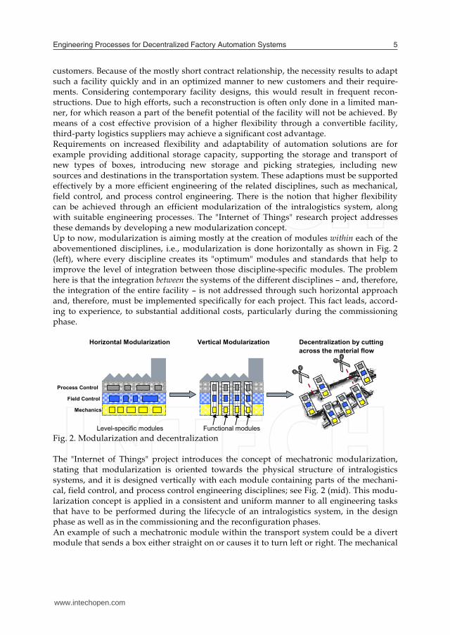
customers. Because of the mostly short contract relationship, the necessity results to adapt such a facility quickly and in an optimized manner to new customers and their require-ments. Considering contemporary facility designs, this would result in frequent recon-structions. Due to high efforts, such a reconstruction is often only done in a limited man-ner, for which reason a part of the benefit potential of the facility will not be achieved. By means of a cost effective provision of a higher flexibility through a convertible facility, third-party logistics suppliers may achieve a significant cost advantage. Requirements on increased flexibility and adaptability of automation solutions are for example providing additional storage capacity, supporting the storage and transport of new types of boxes, introducing new storage and picking strategies, including new sources and destinations in the transportation system. These adaptions must be supported effectively by a more efficient engineering of the related disciplines, such as mechanical, field control, and process control engineering. There is the notion that higher flexibility can be achieved through an efficient modularization of the intralogistics system, along with suitable engineering processes. The "Internet of Things" research project addresses these demands by developing a new modularization concept. Up to now, modularization is aiming mostly at the creation of modules within each of the abovementioned disciplines, i.e., modularization is done horizontally as shown in Fig. 2 (left), where every discipline creates its "optimum" modules and standards that help to improve the level of integration between those discipline-specific modules. The problem here is that the integration between the systems of the different disciplines – and, therefore, the integration of the entire facility – is not addressed through such horizontal approach and, therefore, must be implemented specifically for each project. This fact leads, accord-ing to experience, to substantial additional costs, particularly during the commissioning phase.
Horizontal Modularization Vertical Modularization Decentralization by cutting across the material flow
Process Control
Field Control
Mechanics
Level-specific modules Functional modules Fig. 2. Modularization and decentralization The "Internet of Things" project introduces the concept of mechatronic modularization, stating that modularization is oriented towards the physical structure of intralogistics systems, and it is designed vertically with each module containing parts of the mechani-cal, field control, and process control engineering disciplines; see Fig. 2 (mid). This modu-larization concept is applied in a consistent and uniform manner to all engineering tasks that have to be performed during the lifecycle of an intralogistics system, in the design phase as well as in the commissioning and the reconfiguration phases. An example of such a mechatronic module within the transport system could be a divert module that sends a box either straight on or causes it to turn left or right. The mechanical
www.intechopen.com
Engineering Processes for Decentralized Factory Automation Systems 5
Production flexibility through individual production planning, and optimization, Vertical integration of information and functions at control, MES, and ERP levels, and Fast reconfiguration and scalable capacity through dynamic resource integration
(“Plug’n’Produce”). In the European research project PABADIS'PROMISE, an architectural basis for flexible and vertically seamless production automation was developed. Key features of the ap-proach are: Product driven definition of control processes instead of machine centered definition, Merging of the previously hierarchically separated tasks of control and MES systems, Decentralization of the automation functions into independent, cooperating units. In this approach, the product to be manufactured represents the set point, while the con-trol system is based on an explicit description of product data and production processes (machine independent working processes and parameters). Machine interfaces are de-scribed accordingly in a behavior-oriented manner. The integrated description model serving as basis represents an expansion of the IEC/ISO 62264 Standard (Diep et. al., 2007). Based on these descriptions, the product-specific, on-the-fly configuration of the specific production processes of the production system and the dynamic integration of additional modules at runtime are implemented by means of software agents and RFID technology. Machines and production orders are represented by a logically and physically decentralized agent network (see Fig. 1), which coordinates the production process dy-namically according to machine functions, degree of utilization, and error status, as well as allows the seamless online access from the ERP level to the field level (Lüder, et al., 2007). Fig. 1 depicts an example of decentralized control of an automotive production line where the approach was prototyped.
AutomationUnit AutomationUnit AutomationUnit
AutomationUnit
AutomationUnit AutomationUnitPhysics
Field controlMachinecontrol
AutomationUnitPhysics
Field controlMachinecontrol
PhysicsField control
Machinecontrol
Communication and interaction
Production order unit
Sequence,ParametersProduct data Status
Product process control
Production flow Fig. 1. Decentralized automotive production line acc. to the PABADIS’PROMISE approach
3.2 Flexible, Decentralized Intralogistics Systems The term intralogistics refers to the logistical flow of goods and data "inside the four walls" of a plant. A typical example of an intralogistics system is an automatic high bay warehouse for storage and retrieval of goods in combination with an automated transport system that moves these goods within the plant. Currently, such systems are designed to fulfill a specialized and more or less static workflow. In the future, there will be a stronger demand to support or quickly adapt to different workflows to increase flexibility and adaptability both in the warehouse and in the transport area. A practical application example is the increasing third-party business in the intralogistics area in which logistics companies perform storage and shipping services for one or more
customers. Because of the mostly short contract relationship, the necessity results to adapt such a facility quickly and in an optimized manner to new customers and their require-ments. Considering contemporary facility designs, this would result in frequent recon-structions. Due to high efforts, such a reconstruction is often only done in a limited man-ner, for which reason a part of the benefit potential of the facility will not be achieved. By means of a cost effective provision of a higher flexibility through a convertible facility, third-party logistics suppliers may achieve a significant cost advantage. Requirements on increased flexibility and adaptability of automation solutions are for example providing additional storage capacity, supporting the storage and transport of new types of boxes, introducing new storage and picking strategies, including new sources and destinations in the transportation system. These adaptions must be supported effectively by a more efficient engineering of the related disciplines, such as mechanical, field control, and process control engineering. There is the notion that higher flexibility can be achieved through an efficient modularization of the intralogistics system, along with suitable engineering processes. The "Internet of Things" research project addresses these demands by developing a new modularization concept. Up to now, modularization is aiming mostly at the creation of modules within each of the abovementioned disciplines, i.e., modularization is done horizontally as shown in Fig. 2 (left), where every discipline creates its "optimum" modules and standards that help to improve the level of integration between those discipline-specific modules. The problem here is that the integration between the systems of the different disciplines – and, therefore, the integration of the entire facility – is not addressed through such horizontal approach and, therefore, must be implemented specifically for each project. This fact leads, accord-ing to experience, to substantial additional costs, particularly during the commissioning phase.
Horizontal Modularization Vertical Modularization Decentralization by cutting across the material flow
Process Control
Field Control
Mechanics
Level-specific modules Functional modules Fig. 2. Modularization and decentralization The "Internet of Things" project introduces the concept of mechatronic modularization, stating that modularization is oriented towards the physical structure of intralogistics systems, and it is designed vertically with each module containing parts of the mechani-cal, field control, and process control engineering disciplines; see Fig. 2 (mid). This modu-larization concept is applied in a consistent and uniform manner to all engineering tasks that have to be performed during the lifecycle of an intralogistics system, in the design phase as well as in the commissioning and the reconfiguration phases. An example of such a mechatronic module within the transport system could be a divert module that sends a box either straight on or causes it to turn left or right. The mechanical
www.intechopen.com
Factory Automation6
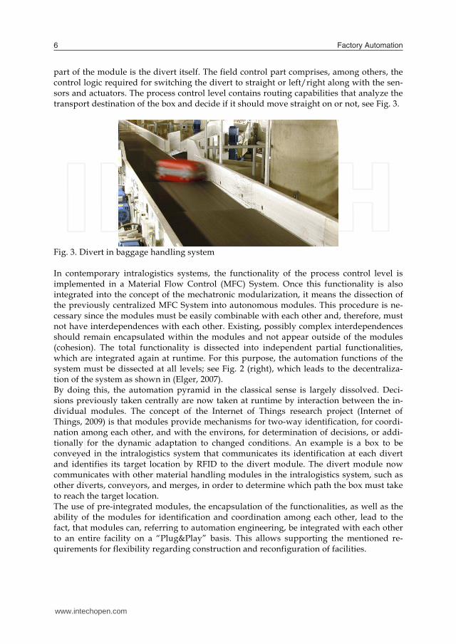
part of the module is the divert itself. The field control part comprises, among others, the control logic required for switching the divert to straight or left/right along with the sen-sors and actuators. The process control level contains routing capabilities that analyze the transport destination of the box and decide if it should move straight on or not, see Fig. 3.
Fig. 3. Divert in baggage handling system In contemporary intralogistics systems, the functionality of the process control level is implemented in a Material Flow Control (MFC) System. Once this functionality is also integrated into the concept of the mechatronic modularization, it means the dissection of the previously centralized MFC System into autonomous modules. This procedure is ne-cessary since the modules must be easily combinable with each other and, therefore, must not have interdependences with each other. Existing, possibly complex interdependences should remain encapsulated within the modules and not appear outside of the modules (cohesion). The total functionality is dissected into independent partial functionalities, which are integrated again at runtime. For this purpose, the automation functions of the system must be dissected at all levels; see Fig. 2 (right), which leads to the decentraliza-tion of the system as shown in (Elger, 2007). By doing this, the automation pyramid in the classical sense is largely dissolved. Deci-sions previously taken centrally are now taken at runtime by interaction between the in-dividual modules. The concept of the Internet of Things research project (Internet of Things, 2009) is that modules provide mechanisms for two-way identification, for coordi-nation among each other, and with the environs, for determination of decisions, or addi-tionally for the dynamic adaptation to changed conditions. An example is a box to be conveyed in the intralogistics system that communicates its identification at each divert and identifies its target location by RFID to the divert module. The divert module now communicates with other material handling modules in the intralogistics system, such as other diverts, conveyors, and merges, in order to determine which path the box must take to reach the target location. The use of pre-integrated modules, the encapsulation of the functionalities, as well as the ability of the modules for identification and coordination among each other, lead to the fact, that modules can, referring to automation engineering, be integrated with each other to an entire facility on a “Plug&Play” basis. This allows supporting the mentioned re-quirements for flexibility regarding construction and reconfiguration of facilities.
4. Essential Aspects in the Life Cycle of Factory Automation Systems
For a comprehensive analysis of a decentralized automation approach, such as the one mentioned above, we need to map it into the context where it is applied – the industrial life cycle. We especially focused our work on the design, realization, installation, and commissioning phases for plants. In the following, the essential aspects of these phases are explained. Factory automation systems – like all other industrial facilities – are complex mechatronic systems according to (VDI 2206), consisting of the synergetic integration of different tech-nical components and partial systems, which together fulfill a specific function. By doing so, the number of identical systems is substantially reduced for larger, more complex so-lutions; while devices and their components are mostly sold as ready products, factories are generally a one of a kind installation constructed under contract based on specific customer requirements. For the installation of a factory, specialists of many technical dis-ciplines participate, such as mechanical engineering, process engineering, energy and automation engineering, informatics, etc., whose extensive knowledge and activities have to be integrated in the project. Within the context of our work, the term Engineering is understood to represent the entire technical working process within a plant project, starting with the concept, and including Detailed Design, Realization, Installation, and Commissioning up to the transfer of the factory Fig. 4). This process contains, particularly, the selection, design, and integration of the components or partial systems of the subsections to an integrated mechatronic system. The objectives of the Engineering are (1) to secure an error-free interaction of the inte-grated components relating to the overall function, and (2) the implementation in a pre-dictable and efficient project development process.
Production op.Plant realization project
Install. & Comm.
Real-izationConceptAqui-
sitionOperation& Control
MaintenanceMaintenance
ServiceService- Engineering:
Customer Requirements
Technical components
Modernization
Technical PlantTechnical Plant
Fig. 4. Engineering of plants – integration of individual components to an entire plant The factory and solution business encompasses the business and technical cooperation of many participants through an often fragmented value-added chain in connection with a high share of purchased components and services that must all be integrated in the con-text of a project. Table 2 shows schematically the most important stakeholders in the in-dustrial life cycle, their particular deliverables/assets, and their different business goals. The effects of an innovative automation concept must be considered separately for each player. It is important to notice that decentralized automation does not only affect the technology, but also changes the respective planning processes and models. The value-adding para-meters in the engineering phases cannot be found in the technology itself, but in their application in plant design and implementation. The most important challenges in plant engineering are (Löwen & Wagner, 2009):
www.intechopen.com

Engineering Processes for Decentralized Factory Automation Systems 7
part of the module is the divert itself. The field control part comprises, among others, the control logic required for switching the divert to straight or left/right along with the sen-sors and actuators. The process control level contains routing capabilities that analyze the transport destination of the box and decide if it should move straight on or not, see Fig. 3.
Fig. 3. Divert in baggage handling system In contemporary intralogistics systems, the functionality of the process control level is implemented in a Material Flow Control (MFC) System. Once this functionality is also integrated into the concept of the mechatronic modularization, it means the dissection of the previously centralized MFC System into autonomous modules. This procedure is ne-cessary since the modules must be easily combinable with each other and, therefore, must not have interdependences with each other. Existing, possibly complex interdependences should remain encapsulated within the modules and not appear outside of the modules (cohesion). The total functionality is dissected into independent partial functionalities, which are integrated again at runtime. For this purpose, the automation functions of the system must be dissected at all levels; see Fig. 2 (right), which leads to the decentraliza-tion of the system as shown in (Elger, 2007). By doing this, the automation pyramid in the classical sense is largely dissolved. Deci-sions previously taken centrally are now taken at runtime by interaction between the in-dividual modules. The concept of the Internet of Things research project (Internet of Things, 2009) is that modules provide mechanisms for two-way identification, for coordi-nation among each other, and with the environs, for determination of decisions, or addi-tionally for the dynamic adaptation to changed conditions. An example is a box to be conveyed in the intralogistics system that communicates its identification at each divert and identifies its target location by RFID to the divert module. The divert module now communicates with other material handling modules in the intralogistics system, such as other diverts, conveyors, and merges, in order to determine which path the box must take to reach the target location. The use of pre-integrated modules, the encapsulation of the functionalities, as well as the ability of the modules for identification and coordination among each other, lead to the fact, that modules can, referring to automation engineering, be integrated with each other to an entire facility on a “Plug&Play” basis. This allows supporting the mentioned re-quirements for flexibility regarding construction and reconfiguration of facilities.
4. Essential Aspects in the Life Cycle of Factory Automation Systems
For a comprehensive analysis of a decentralized automation approach, such as the one mentioned above, we need to map it into the context where it is applied – the industrial life cycle. We especially focused our work on the design, realization, installation, and commissioning phases for plants. In the following, the essential aspects of these phases are explained. Factory automation systems – like all other industrial facilities – are complex mechatronic systems according to (VDI 2206), consisting of the synergetic integration of different tech-nical components and partial systems, which together fulfill a specific function. By doing so, the number of identical systems is substantially reduced for larger, more complex so-lutions; while devices and their components are mostly sold as ready products, factories are generally a one of a kind installation constructed under contract based on specific customer requirements. For the installation of a factory, specialists of many technical dis-ciplines participate, such as mechanical engineering, process engineering, energy and automation engineering, informatics, etc., whose extensive knowledge and activities have to be integrated in the project. Within the context of our work, the term Engineering is understood to represent the entire technical working process within a plant project, starting with the concept, and including Detailed Design, Realization, Installation, and Commissioning up to the transfer of the factory Fig. 4). This process contains, particularly, the selection, design, and integration of the components or partial systems of the subsections to an integrated mechatronic system. The objectives of the Engineering are (1) to secure an error-free interaction of the inte-grated components relating to the overall function, and (2) the implementation in a pre-dictable and efficient project development process.
Production op.Plant realization project
Install. & Comm.
Real-izationConceptAqui-
sitionOperation& Control
MaintenanceMaintenance
ServiceService- Engineering:
Customer Requirements
Technical components
Modernization
Technical PlantTechnical Plant
Fig. 4. Engineering of plants – integration of individual components to an entire plant The factory and solution business encompasses the business and technical cooperation of many participants through an often fragmented value-added chain in connection with a high share of purchased components and services that must all be integrated in the con-text of a project. Table 2 shows schematically the most important stakeholders in the in-dustrial life cycle, their particular deliverables/assets, and their different business goals. The effects of an innovative automation concept must be considered separately for each player. It is important to notice that decentralized automation does not only affect the technology, but also changes the respective planning processes and models. The value-adding para-meters in the engineering phases cannot be found in the technology itself, but in their application in plant design and implementation. The most important challenges in plant engineering are (Löwen & Wagner, 2009):
www.intechopen.com

Factory Automation8
More efficient development and faster time-to-operate by efficient work share, inter-disciplinary cooperation, and continuity in the life cycle,
Reduction of project risk and safeguarding of the project through systematic engineer-ing and continuous validation throughout the project, as well as through cooperation and exchange of information in the supply chain, and
Effect of quantity and increase of quality through repetitive use of modular solutions Consequently, we identified the need to develop appropriate engineering methods and processes for decentralized factory automation systems and to show how they address the challenges listed above. This is the subject of the following chapters.
Stake-holder
Component Suppli-er
Equipment/ Ma-chine Supplier System Integrator Plant Operator/
Owner
Des-crition
Provides automa-tion technology, devices, & compo-nents
Builds machines /plant equipment by using compo-nents
Builds plants, inte-grates equipment and components
Designs products, defines production requirements & workflows
Delive-rables/ Assets
Sensors, drives, PLC, panels, control and MES systems
Robots, CNC or assembly machines, conveyor systems
Technical plant & automation solution
Product model, production process, rough material flow
Exam-ple Depic-tion of Delive-rables /As-sets
Bus-iness Goals
Value added by flexible, integrable components and systems
Value added by in-tegration of com-ponents to market-able machines
Value added by specific integration of systems, equip-ment & components
Flexible, optimized production process, availability and capacity utilization
Scope Make-to-Stock, large numbers Wide application scope
Make-to-Stock/ Adapt-to-Order Domain scope
Make-to-Order Project-oriented
Production scope (ERP to production execution level)
Table 2. Stakeholders in the Industrial Life Cycle
5. Engineering of Decentralized Factory Automation Systems
5.1 Engineering of a Production Line When working on decentralized solutions for automated factory systems, the question was how to plan, design and implement such decentralized automation solutions. For the solution of this problem, an engineering model was developed that describes the possible processes for the engineering of decentralized production automation systems under con-sideration of mechatronic modules. In order to provide a reference, existing engineering
projects were analyzed first and a generalized engineering process for factory automation was documented (Fig. 5) with basic tasks described in Table 3.
MES / ERP Integration
Process Planning
System IntegratorPlant Operator
Plant Layout & Structure
PlanningDetailed Design
Purchasing &Manufacturing
Construction &Commissioning
Fig. 5. Generalized engineering process for factory automation
Phase Basic Engineering Tasks Example Results
Process Planning
Define manufacturing steps and their physical and logical order
Plant Layout & Structure Planning
Derive plant layout from the process description Specify machine types by means of required man-
ufacturing capabilities Specify material transport
Detailed Design
Specify technical details of plant equipment, in-strumentation, and automation (parallel proceed-ing of all involved technical disciplines)
Automation engineering: extend layout by control devices, detail production steps, implement con-trol
S7-4
00
L e iteb e n e K IS S
Ind u str ialE th e rne t
Ba n d 50 L eit ste u e run gB5 0 _ L S T 1
B an d 5 0 W i n C CS t atio n 1
B an d 5 0 W in C CS ta tio n 2
B a n d 5 0 W in CCS tati o n 3 .... .5
D PDP
DPD P
D PD P
D PD P
D PD P
D PDP
N o t - A u s ; P L S ;S c h u tz g i t t e r ; ec t . . . ET 2 0 0 S
P ro fib us m it PR O F Is afe
DPD P
Z o ne 5 S ic he r -h e its - S PS
DPD P
Z o ne 6 S ic he r -h e its - S PS
ET 2 0 0 SV A -M ot o r
E T 2 0 0 SH in te r ac h s e
DPD P
Ba n d 5 0 T ra ns po rt-S te u erun g B 5 0 _T R AN
DPD P
DPD P
A uto m . Fü ge sta tionA AF _ S T 2 0
S ta n db y Füg es ta t io nAS F _ S T 3 0
DPD P
DPD P
A utom . S c hr aub s tat ionA AS _ S T4 0
N ac ha rb eits s ta tio nS T 5 0/6 0 A NS _ 506 0
Prof ib u s-D P
S ie b ert-A n zeig e n
W B T‘s
E K - S ch lüsse l
E C -S ch raub e r
L e se s te ll e nM ob y -I/ E
M o b y -UPr e m id 2 0 d e z
L e se s te ll eM o b y - I
L e se s te lleM o b y - I
L es e s te lleM o b y -I
L e se s te lle5 0 M o b y -IL e se s te lle6 0 M o b y -I
H V O ‘sM P -3 7 0
H V O ‘sM P -2 7 0
H V O ‘sM P -2 7 0
H VO ‘sM P- 2 7 0
H V O ‘sM P -2 7 0
H V O ‘sM P - 3 70
P ro f ib u s-D P
P ro fibu s-D P
P rofib u s -D P
P rof ib u s-DP
P ro f ib u s-DP
Ba n d 5 0 S iche rh e its -S P S B50 _ F 0 01
S7-4
00
S7-4
00
S7-4
00
S7-4
00
S7-4
00
S7-4
00
D PD P
D PD P
D PD P
D PD P
S7-4
00
L e iteb e n e K IS S
Ind u str ialE th e rne t
Ba n d 50 L eit ste u e run gB5 0 _ L S T 1
B an d 5 0 W i n C CS t atio n 1
B an d 5 0 W in C CS ta tio n 2
B a n d 5 0 W in CCS tati o n 3 .... .5
D PDP
DPD P
D PD P
D PD P
D PD P
D PDP
N o t - A u s ; P L S ;S c h u tz g i t t e r ; ec t . . . ET 2 0 0 S
P ro fib us m it PR O F Is afe
DPD P
Z o ne 5 S ic he r -h e its - S PS
DPD P
Z o ne 6 S ic he r -h e its - S PS
ET 2 0 0 SV A -M ot o r
E T 2 0 0 SH in te r ac h s e
DPD P
Ba n d 5 0 T ra ns po rt-S te u erun g B 5 0 _T R AN
DPD P
DPD P
DPD P
DPD P
A uto m . Fü ge sta tionA AF _ S T 2 0
S ta n db y Füg es ta t io nAS F _ S T 3 0
DPD P
DPD P
DPD P
DPD P
A utom . S c hr aub s tat ionA AS _ S T4 0
N ac ha rb eits s ta tio nS T 5 0/6 0 A NS _ 506 0
Prof ib u s-D P
S ie b ert-A n zeig e n
W B T‘s
E K - S ch lüsse l
E C -S ch raub e r
L e se s te ll e nM ob y -I/ E
M o b y -UPr e m id 2 0 d e z
L e se s te ll eM o b y - I
L e se s te lleM o b y - I
L es e s te lleM o b y -I
L e se s te lle5 0 M o b y -IL e se s te lle6 0 M o b y -I
H V O ‘sM P -3 7 0
H V O ‘sM P -2 7 0
H V O ‘sM P -2 7 0
H VO ‘sM P- 2 7 0
H V O ‘sM P -2 7 0
H V O ‘sM P - 3 70
P ro f ib u s-D P
P ro fibu s-D P
P rofib u s -D P
P rof ib u s-DP
P ro f ib u s-DP
Ba n d 5 0 S iche rh e its -S P S B50 _ F 0 01
S7-4
00
S7-4
00
S7-4
00
S7-4
00
S7-4
00
S7-4
00
D PD P
D PD P
D PD P
D PD P
D PD P
D PD P
D PD P
Purchasing & Manu-facturing
Purchase /manufacture devices, equipment, and machines
Construct and implement toward functional units (all involved technical disciplines)
Construc-tion & Commis-sioning
Integrate functional units toward complete plant Verify and optimize machine and process capabili-
ty
MES/ERP Integration
MES: specify the interfaces between control sys-tem and MES system; configure MES system based on the layout and the manufacturing process
ERP: specify the data for exchange; implement the necessary interfaces and communication
Table 3. Phases and Tasks of the Basic Process for Manufacturing System Engineering
5.2 Engineering of a Decentralized Production Line For the case of the development of a facility with decentralized automation, the previous-ly connected automation functionality, in the course of engineering, must be distributed to the individual technical resources (machines, etc.). This corresponds to the principle of vertical (mechatronic) modules as described in Chapter 3.2. For an efficient design of the
www.intechopen.com

Engineering Processes for Decentralized Factory Automation Systems 9
More efficient development and faster time-to-operate by efficient work share, inter-disciplinary cooperation, and continuity in the life cycle,
Reduction of project risk and safeguarding of the project through systematic engineer-ing and continuous validation throughout the project, as well as through cooperation and exchange of information in the supply chain, and
Effect of quantity and increase of quality through repetitive use of modular solutions Consequently, we identified the need to develop appropriate engineering methods and processes for decentralized factory automation systems and to show how they address the challenges listed above. This is the subject of the following chapters.
Stake-holder
Component Suppli-er
Equipment/ Ma-chine Supplier System Integrator Plant Operator/
Owner
Des-crition
Provides automa-tion technology, devices, & compo-nents
Builds machines /plant equipment by using compo-nents
Builds plants, inte-grates equipment and components
Designs products, defines production requirements & workflows
Delive-rables/ Assets
Sensors, drives, PLC, panels, control and MES systems
Robots, CNC or assembly machines, conveyor systems
Technical plant & automation solution
Product model, production process, rough material flow
Exam-ple Depic-tion of Delive-rables /As-sets
Bus-iness Goals
Value added by flexible, integrable components and systems
Value added by in-tegration of com-ponents to market-able machines
Value added by specific integration of systems, equip-ment & components
Flexible, optimized production process, availability and capacity utilization
Scope Make-to-Stock, large numbers Wide application scope
Make-to-Stock/ Adapt-to-Order Domain scope
Make-to-Order Project-oriented
Production scope (ERP to production execution level)
Table 2. Stakeholders in the Industrial Life Cycle
5. Engineering of Decentralized Factory Automation Systems
5.1 Engineering of a Production Line When working on decentralized solutions for automated factory systems, the question was how to plan, design and implement such decentralized automation solutions. For the solution of this problem, an engineering model was developed that describes the possible processes for the engineering of decentralized production automation systems under con-sideration of mechatronic modules. In order to provide a reference, existing engineering
projects were analyzed first and a generalized engineering process for factory automation was documented (Fig. 5) with basic tasks described in Table 3.
MES / ERP Integration
Process Planning
System IntegratorPlant Operator
Plant Layout & Structure
PlanningDetailed Design
Purchasing &Manufacturing
Construction &Commissioning
Fig. 5. Generalized engineering process for factory automation
Phase Basic Engineering Tasks Example Results
Process Planning
Define manufacturing steps and their physical and logical order
Plant Layout & Structure Planning
Derive plant layout from the process description Specify machine types by means of required man-
ufacturing capabilities Specify material transport
Detailed Design
Specify technical details of plant equipment, in-strumentation, and automation (parallel proceed-ing of all involved technical disciplines)
Automation engineering: extend layout by control devices, detail production steps, implement con-trol
S7-4
00
L e iteb e n e K IS S
Ind u str ialE th e rne t
Ba n d 50 L eit ste u e run gB5 0 _ L S T 1
B an d 5 0 W i n C CS t atio n 1
B an d 5 0 W in C CS ta tio n 2
B a n d 5 0 W in CCS tati o n 3 .... .5
D PDP
DPD P
D PD P
D PD P
D PD P
D PDP
N o t - A u s ; P L S ;S c h u tz g i t t e r ; ec t . . . ET 2 0 0 S
P ro fib us m it PR O F Is afe
DPD P
Z o ne 5 S ic he r -h e its - S PS
DPD P
Z o ne 6 S ic he r -h e its - S PS
ET 2 0 0 SV A -M ot o r
E T 2 0 0 SH in te r ac h s e
DPD P
Ba n d 5 0 T ra ns po rt-S te u erun g B 5 0 _T R AN
DPD P
DPD P
A uto m . Fü ge sta tionA AF _ S T 2 0
S ta n db y Füg es ta t io nAS F _ S T 3 0
DPD P
DPD P
A utom . S c hr aub s tat ionA AS _ S T4 0
N ac ha rb eits s ta tio nS T 5 0/6 0 A NS _ 506 0
Prof ib u s-D P
S ie b ert-A n zeig e n
W B T‘s
E K - S ch lüsse l
E C -S ch raub e r
L e se s te ll e nM ob y -I/ E
M o b y -UPr e m id 2 0 d e z
L e se s te ll eM o b y - I
L e se s te lleM o b y - I
L es e s te lleM o b y -I
L e se s te lle5 0 M o b y -IL e se s te lle6 0 M o b y -I
H V O ‘sM P -3 7 0
H V O ‘sM P -2 7 0
H V O ‘sM P -2 7 0
H VO ‘sM P- 2 7 0
H V O ‘sM P -2 7 0
H V O ‘sM P - 3 70
P ro f ib u s-D P
P ro fibu s-D P
P rofib u s -D P
P rof ib u s-DP
P ro f ib u s-DP
Ba n d 5 0 S iche rh e its -S P S B50 _ F 0 01
S7-4
00
S7-4
00
S7-4
00
S7-4
00
S7-4
00
S7-4
00
D PD P
D PD P
D PD P
D PD P
S7-4
00
L e iteb e n e K IS S
Ind u str ialE th e rne t
Ba n d 50 L eit ste u e run gB5 0 _ L S T 1
B an d 5 0 W i n C CS t atio n 1
B an d 5 0 W in C CS ta tio n 2
B a n d 5 0 W in CCS tati o n 3 .... .5
D PDP
DPD P
D PD P
D PD P
D PD P
D PDP
N o t - A u s ; P L S ;S c h u tz g i t t e r ; ec t . . . ET 2 0 0 S
P ro fib us m it PR O F Is afe
DPD P
Z o ne 5 S ic he r -h e its - S PS
DPD P
Z o ne 6 S ic he r -h e its - S PS
ET 2 0 0 SV A -M ot o r
E T 2 0 0 SH in te r ac h s e
DPD P
Ba n d 5 0 T ra ns po rt-S te u erun g B 5 0 _T R AN
DPD P
DPD P
DPD P
DPD P
A uto m . Fü ge sta tionA AF _ S T 2 0
S ta n db y Füg es ta t io nAS F _ S T 3 0
DPD P
DPD P
DPD P
DPD P
A utom . S c hr aub s tat ionA AS _ S T4 0
N ac ha rb eits s ta tio nS T 5 0/6 0 A NS _ 506 0
Prof ib u s-D P
S ie b ert-A n zeig e n
W B T‘s
E K - S ch lüsse l
E C -S ch raub e r
L e se s te ll e nM ob y -I/ E
M o b y -UPr e m id 2 0 d e z
L e se s te ll eM o b y - I
L e se s te lleM o b y - I
L es e s te lleM o b y -I
L e se s te lle5 0 M o b y -IL e se s te lle6 0 M o b y -I
H V O ‘sM P -3 7 0
H V O ‘sM P -2 7 0
H V O ‘sM P -2 7 0
H VO ‘sM P- 2 7 0
H V O ‘sM P -2 7 0
H V O ‘sM P - 3 70
P ro f ib u s-D P
P ro fibu s-D P
P rofib u s -D P
P rof ib u s-DP
P ro f ib u s-DP
Ba n d 5 0 S iche rh e its -S P S B50 _ F 0 01
S7-4
00
S7-4
00
S7-4
00
S7-4
00
S7-4
00
S7-4
00
D PD P
D PD P
D PD P
D PD P
D PD P
D PD P
D PD P
Purchasing & Manu-facturing
Purchase /manufacture devices, equipment, and machines
Construct and implement toward functional units (all involved technical disciplines)
Construc-tion & Commis-sioning
Integrate functional units toward complete plant Verify and optimize machine and process capabili-
ty
MES/ERP Integration
MES: specify the interfaces between control sys-tem and MES system; configure MES system based on the layout and the manufacturing process
ERP: specify the data for exchange; implement the necessary interfaces and communication
Table 3. Phases and Tasks of the Basic Process for Manufacturing System Engineering
5.2 Engineering of a Decentralized Production Line For the case of the development of a facility with decentralized automation, the previous-ly connected automation functionality, in the course of engineering, must be distributed to the individual technical resources (machines, etc.). This corresponds to the principle of vertical (mechatronic) modules as described in Chapter 3.2. For an efficient design of the
www.intechopen.com
Factory Automation10
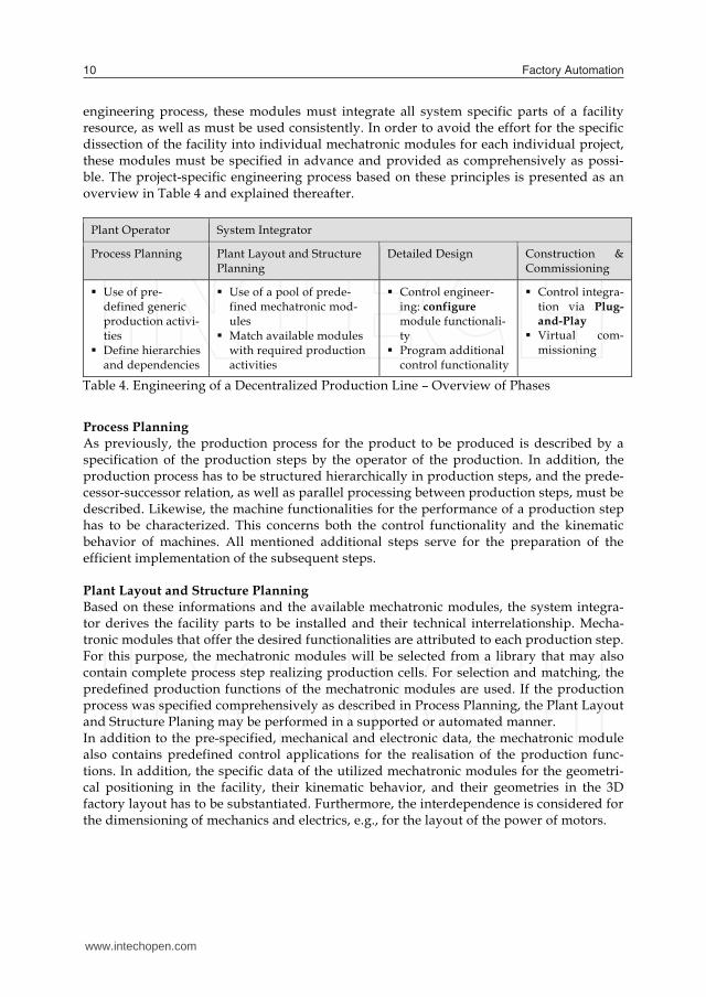
engineering process, these modules must integrate all system specific parts of a facility resource, as well as must be used consistently. In order to avoid the effort for the specific dissection of the facility into individual mechatronic modules for each individual project, these modules must be specified in advance and provided as comprehensively as possi-ble. The project-specific engineering process based on these principles is presented as an overview in Table 4 and explained thereafter.
Plant Operator System Integrator
Process Planning Plant Layout and Structure Planning
Detailed Design Construction & Commissioning
Use of pre-defined generic production activi-ties
Define hierarchies and dependencies
Use of a pool of prede-fined mechatronic mod-ules
Match available modules with required production activities
Control engineer-ing: configure module functionali-ty
Program additional control functionality
Control integra-tion via Plug-and-Play
Virtual com-missioning
Table 4. Engineering of a Decentralized Production Line – Overview of Phases
Process Planning As previously, the production process for the product to be produced is described by a specification of the production steps by the operator of the production. In addition, the production process has to be structured hierarchically in production steps, and the prede-cessor-successor relation, as well as parallel processing between production steps, must be described. Likewise, the machine functionalities for the performance of a production step has to be characterized. This concerns both the control functionality and the kinematic behavior of machines. All mentioned additional steps serve for the preparation of the efficient implementation of the subsequent steps. Plant Layout and Structure Planning Based on these informations and the available mechatronic modules, the system integra-tor derives the facility parts to be installed and their technical interrelationship. Mecha-tronic modules that offer the desired functionalities are attributed to each production step. For this purpose, the mechatronic modules will be selected from a library that may also contain complete process step realizing production cells. For selection and matching, the predefined production functions of the mechatronic modules are used. If the production process was specified comprehensively as described in Process Planning, the Plant Layout and Structure Planing may be performed in a supported or automated manner. In addition to the pre-specified, mechanical and electronic data, the mechatronic module also contains predefined control applications for the realisation of the production func-tions. In addition, the specific data of the utilized mechatronic modules for the geometri-cal positioning in the facility, their kinematic behavior, and their geometries in the 3D factory layout has to be substantiated. Furthermore, the interdependence is considered for the dimensioning of mechanics and electrics, e.g., for the layout of the power of motors.
Detailed Design In the next step, the configuration of the predefined control functionalities of the utilized mechatronic modules is done in accordance with the specific process parameters, and, if necessary, the programming of auxiliary functions is performed. In addition, the connections between mechatronic modules and the corresponding para-meterizations of these connections have to be specified: Connection of electrical, pneumatic, and hydraulic systems, Connection of the communication devices to communication networks, Connection of material flow relations, and Attribution of I/O signals between sensors/actuators and control applications. The connections are generated automatically or manually, depending on to what extent the connections have been specified in advance. PLC and HMI programs are usually generated automatically from the control applications of mechatronic modules. In this planning phase, the design or the adaptation of the facili-ty mechanics (CAD) and the electrical design (CAE) are also done unless large extends have been already predefined in the mechatronic modules. MES/ERP Integration In this planning phase, initially, the interfaces between the predefined process control and MES functions of the mechatronic modules on the one side and the facility MES level on the other side are designed. Engineering data that have to be considered in the design of the MES modules and the facility MES functions are the production process with its specified production steps, the facility layout, and the technical relations of the mechatronic modules in the facility. Once this information is available in a comprehensive manner, the essential tasks can be partially automated. Additionally, control applications have to be adapted to specific MES functionalities – for instance, the scheduling of production – if support still exists. Once the MES functionalities are designed, the parameterization of the interfaces to the ERP system and the synchronization of relevant data between the MES and the ERP system are performed. Construction & Commissioning As the real used facility resources correspond to pre-integrated mechatronic modules, they can be provided in a manner in which they can be integrated into the automation system via plug and play. After corresponding adaptation, these facility parts can be used immediately. Predevelopment of Mechatronic Modules The essential precondition for the feasibility of the engineering of production facilities accord-ing to the described procedure is that, in the run-up, mechatronic modules are prepared in order to be available as a template in a library for the facility planner. This task requires an additional project independent phase and corresponds to a predevelopment (Fig. 6).
www.intechopen.com

Engineering Processes for Decentralized Factory Automation Systems 11
engineering process, these modules must integrate all system specific parts of a facility resource, as well as must be used consistently. In order to avoid the effort for the specific dissection of the facility into individual mechatronic modules for each individual project, these modules must be specified in advance and provided as comprehensively as possi-ble. The project-specific engineering process based on these principles is presented as an overview in Table 4 and explained thereafter.
Plant Operator System Integrator
Process Planning Plant Layout and Structure Planning
Detailed Design Construction & Commissioning
Use of pre-defined generic production activi-ties
Define hierarchies and dependencies
Use of a pool of prede-fined mechatronic mod-ules
Match available modules with required production activities
Control engineer-ing: configure module functionali-ty
Program additional control functionality
Control integra-tion via Plug-and-Play
Virtual com-missioning
Table 4. Engineering of a Decentralized Production Line – Overview of Phases
Process Planning As previously, the production process for the product to be produced is described by a specification of the production steps by the operator of the production. In addition, the production process has to be structured hierarchically in production steps, and the prede-cessor-successor relation, as well as parallel processing between production steps, must be described. Likewise, the machine functionalities for the performance of a production step has to be characterized. This concerns both the control functionality and the kinematic behavior of machines. All mentioned additional steps serve for the preparation of the efficient implementation of the subsequent steps. Plant Layout and Structure Planning Based on these informations and the available mechatronic modules, the system integra-tor derives the facility parts to be installed and their technical interrelationship. Mecha-tronic modules that offer the desired functionalities are attributed to each production step. For this purpose, the mechatronic modules will be selected from a library that may also contain complete process step realizing production cells. For selection and matching, the predefined production functions of the mechatronic modules are used. If the production process was specified comprehensively as described in Process Planning, the Plant Layout and Structure Planing may be performed in a supported or automated manner. In addition to the pre-specified, mechanical and electronic data, the mechatronic module also contains predefined control applications for the realisation of the production func-tions. In addition, the specific data of the utilized mechatronic modules for the geometri-cal positioning in the facility, their kinematic behavior, and their geometries in the 3D factory layout has to be substantiated. Furthermore, the interdependence is considered for the dimensioning of mechanics and electrics, e.g., for the layout of the power of motors.
Detailed Design In the next step, the configuration of the predefined control functionalities of the utilized mechatronic modules is done in accordance with the specific process parameters, and, if necessary, the programming of auxiliary functions is performed. In addition, the connections between mechatronic modules and the corresponding para-meterizations of these connections have to be specified: Connection of electrical, pneumatic, and hydraulic systems, Connection of the communication devices to communication networks, Connection of material flow relations, and Attribution of I/O signals between sensors/actuators and control applications. The connections are generated automatically or manually, depending on to what extent the connections have been specified in advance. PLC and HMI programs are usually generated automatically from the control applications of mechatronic modules. In this planning phase, the design or the adaptation of the facili-ty mechanics (CAD) and the electrical design (CAE) are also done unless large extends have been already predefined in the mechatronic modules. MES/ERP Integration In this planning phase, initially, the interfaces between the predefined process control and MES functions of the mechatronic modules on the one side and the facility MES level on the other side are designed. Engineering data that have to be considered in the design of the MES modules and the facility MES functions are the production process with its specified production steps, the facility layout, and the technical relations of the mechatronic modules in the facility. Once this information is available in a comprehensive manner, the essential tasks can be partially automated. Additionally, control applications have to be adapted to specific MES functionalities – for instance, the scheduling of production – if support still exists. Once the MES functionalities are designed, the parameterization of the interfaces to the ERP system and the synchronization of relevant data between the MES and the ERP system are performed. Construction & Commissioning As the real used facility resources correspond to pre-integrated mechatronic modules, they can be provided in a manner in which they can be integrated into the automation system via plug and play. After corresponding adaptation, these facility parts can be used immediately. Predevelopment of Mechatronic Modules The essential precondition for the feasibility of the engineering of production facilities accord-ing to the described procedure is that, in the run-up, mechatronic modules are prepared in order to be available as a template in a library for the facility planner. This task requires an additional project independent phase and corresponds to a predevelopment (Fig. 6).
www.intechopen.com

Factory Automation12
MES / ERP Integration
System Integrator
Process Planning
Plant Operator
Predevelopment of Mechatronic Modules
Pool of available resources
Plant Layout & Structure
PlanningDetailed Design
Purchasing &Manufacturing
Construction &Commissioning
Plant Layout & Structure
PlanningDetailed Design
Purchasing &Manufacturing
Construction &Commissioning
Fig. 6. Engineering process for decentralized production automation systems based on mechatronic modules During the design of these facility and project independent mechatronic modules, the following information must be specified and provided in an integrated manner: Description of the mechanical parts, e.g., in CAD layout. Description of the behaviors of the facility resource, such as kinematic behavior. Description of the machine functionalities that the resource offers for the design of
production steps (function oriented view). Description of the automatisation portions: control and communication interfaces,
required connections for hydraulics, pneumatics, and electrics, as well as models or implementations of baseline control, HMI, and communication building blocks.
Description of combination possibilities or limitations with other resources in order to combine individual functionalities into one overall functionality.
Fig. 7 shows the information flow for two of the abovementioned phases, which con-verges in an orderly fashion using mechatronic modules.
Fig. 7. Information flow between engineering tasks and modules
5.3 Engineering of a Material Flow System As for the description of the production line scenario, for the engineering of an intralogis-tics material flow system a general engineering process is described; see Table 5, before a
model is presented that offers a possibility for the engineering of the decentralized material flow system. The phases refer to the partitioning of the processes as presented in Fig. 8.
Rough Layout Detailed Layout
Realization & In-house Test
Construction &Commissioning
Design
Fig. 8. Generalized engineering process for intralogistics systems
Phase Basic Engineering Tasks Example Results
Plant Topology and Rough Layout
Deduction of the rough layout based on the required materi-al flow (requirement, particularly in view of transport func-tionalities, storage, handling, throughput of the factory), rough simulation for the detection of bottlenecks
Detailed Layout and Specifica-tions
Refinement and detailed specification of the requirements, establishment of detailed layout, adaptations, optimization of parts lists, concept for electrics, determination of the IT concept, strategies for control algorithms, definition of the interfaces between disciplines, refined simulation based on control algorithms
Realization and In-House Test
Procurement, partial installation, PLC, and IT side configu-ration and programming – related individual tests/interface tests automation/IT
Construction/ Commissioning
Installation of the systems, commissioning of control system, test of IT interfaces with other processes
Table 5. Phases and Tasks of Basic Process for Engineering of Material Flow System
5.4 Engineering of a Decentralized Material Flow System As shown in Chapter 3.2, the request for flexible integration and reconfiguration of an intralogistics system could be realized by the creation and continuous use of mechatronic modules. For this purpose, previously centralized automation functionalities are distri-buted to individual modules, which leads to the decentralization of the intralogistics sys-tem. As explained there, this approach has implications on the architecture of the automation system and, therefore, on the handling of the modules. This is reflected by the introduc-tion of an engineering process for decentralized systems that supports the engineering in the design, commissioning, and reconfiguration phases. This will be presented hereafter.
www.intechopen.com

Engineering Processes for Decentralized Factory Automation Systems 13
MES / ERP Integration
System Integrator
Process Planning
Plant Operator
Predevelopment of Mechatronic Modules
Pool of available resources
Plant Layout & Structure
PlanningDetailed Design
Purchasing &Manufacturing
Construction &Commissioning
Plant Layout & Structure
PlanningDetailed Design
Purchasing &Manufacturing
Construction &Commissioning
Fig. 6. Engineering process for decentralized production automation systems based on mechatronic modules During the design of these facility and project independent mechatronic modules, the following information must be specified and provided in an integrated manner: Description of the mechanical parts, e.g., in CAD layout. Description of the behaviors of the facility resource, such as kinematic behavior. Description of the machine functionalities that the resource offers for the design of
production steps (function oriented view). Description of the automatisation portions: control and communication interfaces,
required connections for hydraulics, pneumatics, and electrics, as well as models or implementations of baseline control, HMI, and communication building blocks.
Description of combination possibilities or limitations with other resources in order to combine individual functionalities into one overall functionality.
Fig. 7 shows the information flow for two of the abovementioned phases, which con-verges in an orderly fashion using mechatronic modules.
Fig. 7. Information flow between engineering tasks and modules
5.3 Engineering of a Material Flow System As for the description of the production line scenario, for the engineering of an intralogis-tics material flow system a general engineering process is described; see Table 5, before a
model is presented that offers a possibility for the engineering of the decentralized material flow system. The phases refer to the partitioning of the processes as presented in Fig. 8.
Rough Layout Detailed Layout
Realization & In-house Test
Construction &Commissioning
Design
Fig. 8. Generalized engineering process for intralogistics systems
Phase Basic Engineering Tasks Example Results
Plant Topology and Rough Layout
Deduction of the rough layout based on the required materi-al flow (requirement, particularly in view of transport func-tionalities, storage, handling, throughput of the factory), rough simulation for the detection of bottlenecks
Detailed Layout and Specifica-tions
Refinement and detailed specification of the requirements, establishment of detailed layout, adaptations, optimization of parts lists, concept for electrics, determination of the IT concept, strategies for control algorithms, definition of the interfaces between disciplines, refined simulation based on control algorithms
Realization and In-House Test
Procurement, partial installation, PLC, and IT side configu-ration and programming – related individual tests/interface tests automation/IT
Construction/ Commissioning
Installation of the systems, commissioning of control system, test of IT interfaces with other processes
Table 5. Phases and Tasks of Basic Process for Engineering of Material Flow System
5.4 Engineering of a Decentralized Material Flow System As shown in Chapter 3.2, the request for flexible integration and reconfiguration of an intralogistics system could be realized by the creation and continuous use of mechatronic modules. For this purpose, previously centralized automation functionalities are distri-buted to individual modules, which leads to the decentralization of the intralogistics sys-tem. As explained there, this approach has implications on the architecture of the automation system and, therefore, on the handling of the modules. This is reflected by the introduc-tion of an engineering process for decentralized systems that supports the engineering in the design, commissioning, and reconfiguration phases. This will be presented hereafter.
www.intechopen.com

Factory Automation14
Plant Topology and Rough Layout As common, a rough layout is created, based on the customer requirements and the speci-fications of the factory planners, that describes the general topology of the system and all source/target relations. From this layout, the system integrator identifies the factory parts to be installed and their technical interrelations as depicted in Fig. 9. These factory parts may consist of one or more mechatronic modules. One example for a factory part consist-ing of several modules is a buffer storage unit for intermediate storage of boxes, consist-ing of the material handling modules, a rack, and an automated storage and retrieval sys-tem (AS/RS). In this phase, not only the factory components but also the mechatronic modules are still generic. For example, it is determined where the buffer storage unit is located in the to-pology, how many spaces it must have, which throughput it performs, and which func-tions are generally required. But it is not yet defined which particular conveyor types and which AS/RS will be used. At this time, a rough simulation of the process is performed for the verification of the throughput.
Fig. 9. Identification of appropriate modules Detailed Layout and Specification Now, a successive refinement of the developed requirements and definitions is done in a top-down approach. Initially, the requirements for the mechatronic modules are further detailed. Then, it is determined which mechatronic modules will be used in reality, e.g., the conveyor of Company A, that can move a certain maximum load, and a rack feeder of Company B. At this time, the identification of components to be developed specifically for the project is also made, such as, for example, a special gripping device for the rack feeder for the nonstandard boxes of the customer, including the corresponding automation sys-tem. In this phase, the control and process concepts are specified. In opposite to central auto-mation, in which the process logic can be explicitly specified, the procedures may only be defined through the rules of interrelations. As an example, the control of a transport process by driverless transport systems (Automated Guided Vehicles, AGV) can be consi-dered. This control can be implemented by a framework of auctions. A bid for the box transport can be requested by the box while the AGVs will provide it based on availability of the corresponding AGV, its actual location, its transport capacity, and other parame-ters. The box transport than shall be assigned to the AGV with the most “beneficial” bid.
That means that the engineering process is performed at a more abstract level; the possi-bilities of interactions of the modules must be very familiar to the developer. Then, a re-fined simulation of the processes is performed. This simulation exploits functionalities of the mechatronic modules used later on in the actual operation in suitable granularity in-troducing them into the simulation by Plug&Play. This simulation allows the rough test-ing of the effects of different control concepts (i.e., different system configurations). This also allows identifying components and rules to be developed specifically for the project. The interfaces between the modules are defined using standardized interface descriptions. The interfaces of the mechatronic material flow system to superimposed processes (e.g., ERP system or Warehouse Management System) and neighboring processes (e.g., the production control system) are defined. In addition, the connections of the mechatronic modules to the central infrastructure components are defined, such as, e.g., electrical power supply, compressed air supply, and connection to the IT network. Realization and In-House Test The individual mechatronic modules are configured and parameterized for their particu-lar task in accordance with the requirements of the established specifications. For this purpose, the specialists of the different technical disciplines continue to work on their specific tasks. However, its work is based on consistent mechatronic modules that provide the corresponding views. The necessary project-specific designs are performed. Based on the control concept and the defined possibilities for communication and coordination between the modules, the concrete control mechanisms are configured and project-specifically extended if necessary. The functionality per se is generated at runtime by using defined rules. An in-house test of the system is performed during which a pretest of the facility is done to the possible extent. The vertically modularized structure and the “Plug&Play” functio-nality support virtual commissioning by subjecting readily configured or installed facility parts to the test and recreate others that are not completed by simulation or emulation. Construction/Commissioning During the commissioning phase, the “Plug&Play” functionality, i.e., the use of pre-integrated modules with the capability to identify each other and coordinate among each other, is applied. It allows a bottom-up installation of the factory according to the factory layout. The physical modules possess mechanisms in order to recognize at which position of the factory topology they are located and perform their configuration and parameteri-zation based on their specifications. They connect themselves with their neighboring modules in terms of automation and communicate with each other as illustrated in Fig. 10. The use of pre-integrated mechatronic modules allows a functionality oriented installation of the factory and, therefore, an early testing of interconnected partial areas and, specifi-cally, an early start of the commissioning of the automation. It is not necessary to inte-grate completely mechanics and electrics before commissioning the automation, but it is possible to combine and test small functional units such as, for instance, a material hand-ling circuit that is able to move boxes while additional integration still occurs around it.
www.intechopen.com

Engineering Processes for Decentralized Factory Automation Systems 15
Plant Topology and Rough Layout As common, a rough layout is created, based on the customer requirements and the speci-fications of the factory planners, that describes the general topology of the system and all source/target relations. From this layout, the system integrator identifies the factory parts to be installed and their technical interrelations as depicted in Fig. 9. These factory parts may consist of one or more mechatronic modules. One example for a factory part consist-ing of several modules is a buffer storage unit for intermediate storage of boxes, consist-ing of the material handling modules, a rack, and an automated storage and retrieval sys-tem (AS/RS). In this phase, not only the factory components but also the mechatronic modules are still generic. For example, it is determined where the buffer storage unit is located in the to-pology, how many spaces it must have, which throughput it performs, and which func-tions are generally required. But it is not yet defined which particular conveyor types and which AS/RS will be used. At this time, a rough simulation of the process is performed for the verification of the throughput.
Fig. 9. Identification of appropriate modules Detailed Layout and Specification Now, a successive refinement of the developed requirements and definitions is done in a top-down approach. Initially, the requirements for the mechatronic modules are further detailed. Then, it is determined which mechatronic modules will be used in reality, e.g., the conveyor of Company A, that can move a certain maximum load, and a rack feeder of Company B. At this time, the identification of components to be developed specifically for the project is also made, such as, for example, a special gripping device for the rack feeder for the nonstandard boxes of the customer, including the corresponding automation sys-tem. In this phase, the control and process concepts are specified. In opposite to central auto-mation, in which the process logic can be explicitly specified, the procedures may only be defined through the rules of interrelations. As an example, the control of a transport process by driverless transport systems (Automated Guided Vehicles, AGV) can be consi-dered. This control can be implemented by a framework of auctions. A bid for the box transport can be requested by the box while the AGVs will provide it based on availability of the corresponding AGV, its actual location, its transport capacity, and other parame-ters. The box transport than shall be assigned to the AGV with the most “beneficial” bid.
That means that the engineering process is performed at a more abstract level; the possi-bilities of interactions of the modules must be very familiar to the developer. Then, a re-fined simulation of the processes is performed. This simulation exploits functionalities of the mechatronic modules used later on in the actual operation in suitable granularity in-troducing them into the simulation by Plug&Play. This simulation allows the rough test-ing of the effects of different control concepts (i.e., different system configurations). This also allows identifying components and rules to be developed specifically for the project. The interfaces between the modules are defined using standardized interface descriptions. The interfaces of the mechatronic material flow system to superimposed processes (e.g., ERP system or Warehouse Management System) and neighboring processes (e.g., the production control system) are defined. In addition, the connections of the mechatronic modules to the central infrastructure components are defined, such as, e.g., electrical power supply, compressed air supply, and connection to the IT network. Realization and In-House Test The individual mechatronic modules are configured and parameterized for their particu-lar task in accordance with the requirements of the established specifications. For this purpose, the specialists of the different technical disciplines continue to work on their specific tasks. However, its work is based on consistent mechatronic modules that provide the corresponding views. The necessary project-specific designs are performed. Based on the control concept and the defined possibilities for communication and coordination between the modules, the concrete control mechanisms are configured and project-specifically extended if necessary. The functionality per se is generated at runtime by using defined rules. An in-house test of the system is performed during which a pretest of the facility is done to the possible extent. The vertically modularized structure and the “Plug&Play” functio-nality support virtual commissioning by subjecting readily configured or installed facility parts to the test and recreate others that are not completed by simulation or emulation. Construction/Commissioning During the commissioning phase, the “Plug&Play” functionality, i.e., the use of pre-integrated modules with the capability to identify each other and coordinate among each other, is applied. It allows a bottom-up installation of the factory according to the factory layout. The physical modules possess mechanisms in order to recognize at which position of the factory topology they are located and perform their configuration and parameteri-zation based on their specifications. They connect themselves with their neighboring modules in terms of automation and communicate with each other as illustrated in Fig. 10. The use of pre-integrated mechatronic modules allows a functionality oriented installation of the factory and, therefore, an early testing of interconnected partial areas and, specifi-cally, an early start of the commissioning of the automation. It is not necessary to inte-grate completely mechanics and electrics before commissioning the automation, but it is possible to combine and test small functional units such as, for instance, a material hand-ling circuit that is able to move boxes while additional integration still occurs around it.
www.intechopen.com

Factory Automation16
Fig. 10. Simplified Integration Reconfiguration Even in existing plants, reconfiguration procedures occur. They generally require exten-sive engineering processes. If, for instance, additional diverts shall be included in the automatic transport system mentioned above in order to be able to move to different loca-tions, an entire engineering process needs to be performed for such a change. Then, the mechanics of the transport system must be separated at the plant locations in the context of the commissioning, the diverts must be mechanically installed, and subsequently, the electrics and the automation system must be installed and newly commissioned.
Fig. 11. Simplified Adaption to Changes In the case of the decentralized mechatronic system, these activities are supported by the “Plug&Play” functionality of the modules. Modules can be removed from the overall system without causing far-reaching changes to the automation system (dynamic adapta-tion to changed topology) as shown in Fig. 11. In terms of automation, new modules, to a large extent, are autonomously integrated into an existing plant. The required extent of the engineering depends essentially, in this example, on the requirements for actuality
and consistency in the plant documentation, such as, for example, the updating of the plant layout. Predevelopment of Mechatronic Modules In order to keep the project specific effort for the use of these modules as low as possible, they must be defined and specified as far as possible in advance, also for the intralogistics system as described in Chapter 5.2. This means the creation of mechatronic module build-ing blocks that are defined independent of specific projects. These modules provide all involved disciplines with their particular views using a consistent model. The building block approach supports the top down proceeding during the design phase by the provi-sioning of module descriptions based on which the initially still rough plant layout can be refined successively. Therefore, standardized means of descriptions must be applied. They contain required module information related to the different disciplines or to the proposed (transport) services, for instance. In an intralogistics system there are functionalities that require comprehensive information, such as, the routing of a box to its target destination or the allocation of plant resources to tasks based on the current load of the system (e.g., selection of automated sto-rage/retrieval system, AS/RS). They were previously performed through central systems. Such functionalities have to be replaced for decentralized plants by other mechanisms. This includes concepts for the substitution and distribution of such control logics, capabil-ities for communication, as well as for coordination of the modules, such as auctions. For instance, the decision finding for allocating a storage order to an AS/RS, is done rule-based in the decentralized case. Formerly, a central system maintained information about the load of the AS/RS and made decisions for a suitable device. Now, whether an AS/RS may offer its services or not has to be determined by rules. In addition, it must be deter-mined according to which rules the devices coordinate among each other about the alloca-tion of an order and, lastly, select one of them for the execution of the storage order.
6. Methodical Evaluation of Benefits and Risks
Changes, such as the introduction of mechatronic modules, a mechatronic approach in engineering, distributed control logic, and function-oriented commissioning, are only supportable if their impact, in terms of benefits and risks, on the entire industrial life cycle, has first been worked out in detail (Löwen, et al., 2005). For the planning, realization, and commissioning phases, there is no well known proce-dure through which the added value of an automation concept can be determined. Re-garding the introduction of new concepts, it is of high importance to evaluate benefits and risks before the actual practical deployment. Although an effort-and-cost based evaluation would be desirable, the lack of completed projects and reliable figures prevents the use of such an evaluation. In order to close this gap, an evaluation strategy was developed with-in the PABADIS'PROMISE and “Internet of Things” research projects. The basic idea of the method is the creation of reference models for engineering processes and activities along the life cycle of an automation solution. These models refer to the corresponding automation concepts, for instance, the classically developed system and the decentralized automation system developed mechatronically, to compare both.
www.intechopen.com

Engineering Processes for Decentralized Factory Automation Systems 17
Fig. 10. Simplified Integration Reconfiguration Even in existing plants, reconfiguration procedures occur. They generally require exten-sive engineering processes. If, for instance, additional diverts shall be included in the automatic transport system mentioned above in order to be able to move to different loca-tions, an entire engineering process needs to be performed for such a change. Then, the mechanics of the transport system must be separated at the plant locations in the context of the commissioning, the diverts must be mechanically installed, and subsequently, the electrics and the automation system must be installed and newly commissioned.
Fig. 11. Simplified Adaption to Changes In the case of the decentralized mechatronic system, these activities are supported by the “Plug&Play” functionality of the modules. Modules can be removed from the overall system without causing far-reaching changes to the automation system (dynamic adapta-tion to changed topology) as shown in Fig. 11. In terms of automation, new modules, to a large extent, are autonomously integrated into an existing plant. The required extent of the engineering depends essentially, in this example, on the requirements for actuality
and consistency in the plant documentation, such as, for example, the updating of the plant layout. Predevelopment of Mechatronic Modules In order to keep the project specific effort for the use of these modules as low as possible, they must be defined and specified as far as possible in advance, also for the intralogistics system as described in Chapter 5.2. This means the creation of mechatronic module build-ing blocks that are defined independent of specific projects. These modules provide all involved disciplines with their particular views using a consistent model. The building block approach supports the top down proceeding during the design phase by the provi-sioning of module descriptions based on which the initially still rough plant layout can be refined successively. Therefore, standardized means of descriptions must be applied. They contain required module information related to the different disciplines or to the proposed (transport) services, for instance. In an intralogistics system there are functionalities that require comprehensive information, such as, the routing of a box to its target destination or the allocation of plant resources to tasks based on the current load of the system (e.g., selection of automated sto-rage/retrieval system, AS/RS). They were previously performed through central systems. Such functionalities have to be replaced for decentralized plants by other mechanisms. This includes concepts for the substitution and distribution of such control logics, capabil-ities for communication, as well as for coordination of the modules, such as auctions. For instance, the decision finding for allocating a storage order to an AS/RS, is done rule-based in the decentralized case. Formerly, a central system maintained information about the load of the AS/RS and made decisions for a suitable device. Now, whether an AS/RS may offer its services or not has to be determined by rules. In addition, it must be deter-mined according to which rules the devices coordinate among each other about the alloca-tion of an order and, lastly, select one of them for the execution of the storage order.
6. Methodical Evaluation of Benefits and Risks
Changes, such as the introduction of mechatronic modules, a mechatronic approach in engineering, distributed control logic, and function-oriented commissioning, are only supportable if their impact, in terms of benefits and risks, on the entire industrial life cycle, has first been worked out in detail (Löwen, et al., 2005). For the planning, realization, and commissioning phases, there is no well known proce-dure through which the added value of an automation concept can be determined. Re-garding the introduction of new concepts, it is of high importance to evaluate benefits and risks before the actual practical deployment. Although an effort-and-cost based evaluation would be desirable, the lack of completed projects and reliable figures prevents the use of such an evaluation. In order to close this gap, an evaluation strategy was developed with-in the PABADIS'PROMISE and “Internet of Things” research projects. The basic idea of the method is the creation of reference models for engineering processes and activities along the life cycle of an automation solution. These models refer to the corresponding automation concepts, for instance, the classically developed system and the decentralized automation system developed mechatronically, to compare both.
www.intechopen.com

Factory Automation18
Fig. 12. Meta-model for structural and attributive features of engineering task The creation of such a model is done by dissecting the life cycle of the plant in its phases, by the dissection of the processes (e.g., layout planning) within the individual phases into individual activities, and by the identification of their relation with the automation sys-tem. For the creation of a neutral reference basis for the later comparison of different automa-tion concepts, a meta-model was developed; see Fig. 12, which defines all required fea-tures of the corresponding reference models for engineering and commissioning in a uni-form manner. As an auxiliary tool for building the reference models, corresponding tem-plates were created to record activities/processes. The evaluation is done by a comparative assessment. As one of the basics depicted in Ta-ble 6, generally applicable evaluation criteria were defined, derived from central levers in factory engineering, such as modularization, re-use, integration, and seamlessness (Löwen et. al., 2005), as well as under the viewpoint of applicability. They serve as guid-ing issues for the identification of critical factors in engineering and address specifically the challenges concerning the phases mentioned in Chapter 4. In addition, the standard ISO/IEC 9126, which regards the assurance of software quality, was evaluated, and the quality characteristics included therein were transferred, adapted, and amended to meet the requirements of plant business. The criteria catalogue thusly generated serves as the basis for the evaluation; an excerpt of questions can be found in Table 6.
Topic Criteria Question Details
Suitabi-lity
Customer require-ments
Which customer require-ments are relevant for the system integrator in order to design and realize the plant?
Typical customer requirements today aims of system
Control architecture specific requirements
Appro-priateness
Are the requirements con-sidered in a suitable way?
e.g., highly redundant (and costly) automa-tion system in case of non-time-critical processes is not appropriate
Inter-opera-bility
Content-related de-pendencies between activities
Which dependencies dur-ing the engineering process do exist between automa-tion engineering and other disciplines?
required information from mechanical engineering, electrical engineering and mechanical plant layout
processes to be controlled/monitored, list of process signals
sensors/variables to measure the process actuators/variables to influence the
process
View inte-gration
How is cooperation of technical disciplines sup-ported?
e.g., integrated information models such as multi-discipline information objects
Table 6. Excerpt of Criteria Catalogue
For the automation concepts to be compared, according to the evaluation proceeding as shown in Fig. 13, a reference model is initially established for the processes and activities along the life cycle. The information in Chapter 5 serve as a basis for the creation of these models for the presented automation solutions. Subsequently, the different models are analyzed based on the evaluation criteria and compared to each other related to benefits and disadvantages. In the following, the results of the comparison of centralized to decen-tralized automation systems shall be presented.
As Is - Engineering Process
To Be - Engineering Process
ComparativeEvaluation
Meta-Model forEngineering
Process
Evaluation Criteria
EvaluationBasics Fig. 13. Basics and evaluation proceeding of reference model method
7. Implications for the Engineering Processes
The detailed gathering and analysis of the individual processes and activities for both decentralized production systems and, also, decentralized material flow systems showed very similar results as compared to previous engineering processes. To begin with, the following findings are related to the activities to be performed and the resulting (ex-pected) efforts.
www.intechopen.com

Engineering Processes for Decentralized Factory Automation Systems 19
Fig. 12. Meta-model for structural and attributive features of engineering task The creation of such a model is done by dissecting the life cycle of the plant in its phases, by the dissection of the processes (e.g., layout planning) within the individual phases into individual activities, and by the identification of their relation with the automation sys-tem. For the creation of a neutral reference basis for the later comparison of different automa-tion concepts, a meta-model was developed; see Fig. 12, which defines all required fea-tures of the corresponding reference models for engineering and commissioning in a uni-form manner. As an auxiliary tool for building the reference models, corresponding tem-plates were created to record activities/processes. The evaluation is done by a comparative assessment. As one of the basics depicted in Ta-ble 6, generally applicable evaluation criteria were defined, derived from central levers in factory engineering, such as modularization, re-use, integration, and seamlessness (Löwen et. al., 2005), as well as under the viewpoint of applicability. They serve as guid-ing issues for the identification of critical factors in engineering and address specifically the challenges concerning the phases mentioned in Chapter 4. In addition, the standard ISO/IEC 9126, which regards the assurance of software quality, was evaluated, and the quality characteristics included therein were transferred, adapted, and amended to meet the requirements of plant business. The criteria catalogue thusly generated serves as the basis for the evaluation; an excerpt of questions can be found in Table 6.
Topic Criteria Question Details
Suitabi-lity
Customer require-ments
Which customer require-ments are relevant for the system integrator in order to design and realize the plant?
Typical customer requirements today aims of system
Control architecture specific requirements
Appro-priateness
Are the requirements con-sidered in a suitable way?
e.g., highly redundant (and costly) automa-tion system in case of non-time-critical processes is not appropriate
Inter-opera-bility
Content-related de-pendencies between activities
Which dependencies dur-ing the engineering process do exist between automa-tion engineering and other disciplines?
required information from mechanical engineering, electrical engineering and mechanical plant layout
processes to be controlled/monitored, list of process signals
sensors/variables to measure the process actuators/variables to influence the
process
View inte-gration
How is cooperation of technical disciplines sup-ported?
e.g., integrated information models such as multi-discipline information objects
Table 6. Excerpt of Criteria Catalogue
For the automation concepts to be compared, according to the evaluation proceeding as shown in Fig. 13, a reference model is initially established for the processes and activities along the life cycle. The information in Chapter 5 serve as a basis for the creation of these models for the presented automation solutions. Subsequently, the different models are analyzed based on the evaluation criteria and compared to each other related to benefits and disadvantages. In the following, the results of the comparison of centralized to decen-tralized automation systems shall be presented.
As Is - Engineering Process
To Be - Engineering Process
ComparativeEvaluation
Meta-Model forEngineering
Process
Evaluation Criteria
EvaluationBasics Fig. 13. Basics and evaluation proceeding of reference model method
7. Implications for the Engineering Processes
The detailed gathering and analysis of the individual processes and activities for both decentralized production systems and, also, decentralized material flow systems showed very similar results as compared to previous engineering processes. To begin with, the following findings are related to the activities to be performed and the resulting (ex-pected) efforts.
www.intechopen.com

Factory Automation20
Predevelopment: For the creation of mechatronic blocks, a correspondingly higher effort has to be undertaken for predevelopment. This includes: Adequate definition of standard modules with as few as possible technical and func-
tional dependencies by systematic dissection of a plant, Coordination across the involved disciplines for the generation of mechatronic
modules Standardized interface descriptions (functional, technical, information technical), Standardized description of process functions or partial processes provided
by a module, Description of sequences of processes and the invocation of process functions, Provision of configuration possibilities and interfaces for project specific adaptations, Provision of module-specific automation control functionality and its implementation, Provision of application guidelines for modules (e.g., application areas, limitations,
dependency on configuration possibilities, and variants). The creation process for mechatronic module building blocks has to be done in coopera-tion and coordination with all participating stakeholders (system integrator, equip-ment/machine supplier, and component supplier).
Layout, Detailed Design, and Realization: By means of the project-independent creation of mechatronic modules, a shifting of engineering processes to earlier phases results: Control engineering is not an individual task any more, but is derived from models of
the production process and of mechatronic modules. Depending on the reuse concept and the grade of standardization appropriate in this
domain, the engineering process is essentially reduced to the selection and adaptation of the utilized modules through configuration.
By means of the Plug&Play characteristics (predefined functionalities and coordinated interfaces) and the mechatronic building blocks, simulation or emulation can be used in a more realistic way for the mapping of the plant (use of the same software modules in both the automation system and the simulation).
The mechatronic approach supports parallel work and coordination across the involved disciplines for project specific engineering tasks. Installation/Commissioning: Here, mainly the Plug&Play characteristics and the pre-integrated mechatronic modules are used: The effort for installation and commissioning can be reduced since essential functional
and technical aspects in the modules have already been pre-integrated. This includes, particularly, the integration of the control system and MES functionalities.
The existing mechatronic information and the detailed emulation possibilities facilitate virtual commissioning.
Through standardized interface definitions and the use of proven modules, the inte-gration risks can be reduced.
By using mechatronic modules, a stronger focusing on rapid availability/completion of functionalities is possible during installation (installation according to functional areas and not according to diciplines). This also allows a faster completion of tests.
In summary, regarding the engineering efforts in projects, efforts are shifted from design and commissioning to process planning and plant layout. This is valid for both engineer-
ing of production lines and material flow systems. I.e., efforts are moved towards earlier phases in the project; see Fig. 14. Additional efforts (project independent) will be required for the development and maintenance of module libraries. The benefits occur in plant realization, commissioning, and reconfiguration. Standardization and reuse in terms of generic utilizable resources will reduce total costs in the long term.
MES / ERP Integration
Process Planning
Plant Layout & Structure
PlanningDetailed Design
Purchasing &Manufacturing
Construction &Commissioning
Predevelopment of Mechatronic
Modules
1:n
Expected Project EffortsCurrent Project Efforts
Project independent
efforts Fig. 14. Expected shifting of efforts, exemplary for engineering for production lines
8. Comparison of the Engineering Approaches and Conclusions
The collected information related to the activities along the life cycle of an automation solution serves as basis for the comparative evaluation between a classically developed system and a mechatronicly developed decentralized system. The following results have been worked out with the characteristics from decentralized automation use cases as in-troduced in Section 3 in combination with the described mechatronic engineering ap-proaches. The general advantages of engineering with mechatronic modules, such as, for instance, cross-discipline- work and the improved reuse or standardization of partial solu-tions, were already discussed in other papers and shall not be described here any further (Thramboulidis 2008, Löwen & Wagner 2009, VDI 2206). Application Effort and Complexity: The applicability and manageability of a modular, decentralized automation approach – particularly regarding the modularization of auto-mation and control functionalities – must still be ensured. For this purpose, one must differentiate between the creation of the mechatronically modules in a predevelopment project and their application in the particular engineering projects. Overall, it can be ex-pected that the specification and implementation effort to be performed in advance and the complexity for the creation of mechatronic modules with integrated automation and control functions, which are autonomous and can be integrated independently of each other, will increase substantially. For this purpose, bases for modules have to be created that are usable for different projects and configurable for the specific applications. This requires detailed knowledge of the domain, extensive technological expertise, and an understanding of the core functionality of the modules. One example for a starting point for this approach is the INTEGRA standard specifying first consistent mechatronic view-points for automotive production lines. These pre-produced modules facilitate the engineering for project-specific applications. The more plug&play modules are available the less effort is required for the engineering. In addition, project risks can be reduced by early validation of fulfillment of customer requirements due to availability of module descriptions and models. This, however, only applies if module adaptations occur which can be done by configuration, selection of va-riants, or extensions, and in which do not require any changes to the predefined core
www.intechopen.com

Engineering Processes for Decentralized Factory Automation Systems 21
Predevelopment: For the creation of mechatronic blocks, a correspondingly higher effort has to be undertaken for predevelopment. This includes: Adequate definition of standard modules with as few as possible technical and func-
tional dependencies by systematic dissection of a plant, Coordination across the involved disciplines for the generation of mechatronic
modules Standardized interface descriptions (functional, technical, information technical), Standardized description of process functions or partial processes provided
by a module, Description of sequences of processes and the invocation of process functions, Provision of configuration possibilities and interfaces for project specific adaptations, Provision of module-specific automation control functionality and its implementation, Provision of application guidelines for modules (e.g., application areas, limitations,
dependency on configuration possibilities, and variants). The creation process for mechatronic module building blocks has to be done in coopera-tion and coordination with all participating stakeholders (system integrator, equip-ment/machine supplier, and component supplier).
Layout, Detailed Design, and Realization: By means of the project-independent creation of mechatronic modules, a shifting of engineering processes to earlier phases results: Control engineering is not an individual task any more, but is derived from models of
the production process and of mechatronic modules. Depending on the reuse concept and the grade of standardization appropriate in this
domain, the engineering process is essentially reduced to the selection and adaptation of the utilized modules through configuration.
By means of the Plug&Play characteristics (predefined functionalities and coordinated interfaces) and the mechatronic building blocks, simulation or emulation can be used in a more realistic way for the mapping of the plant (use of the same software modules in both the automation system and the simulation).
The mechatronic approach supports parallel work and coordination across the involved disciplines for project specific engineering tasks. Installation/Commissioning: Here, mainly the Plug&Play characteristics and the pre-integrated mechatronic modules are used: The effort for installation and commissioning can be reduced since essential functional
and technical aspects in the modules have already been pre-integrated. This includes, particularly, the integration of the control system and MES functionalities.
The existing mechatronic information and the detailed emulation possibilities facilitate virtual commissioning.
Through standardized interface definitions and the use of proven modules, the inte-gration risks can be reduced.
By using mechatronic modules, a stronger focusing on rapid availability/completion of functionalities is possible during installation (installation according to functional areas and not according to diciplines). This also allows a faster completion of tests.
In summary, regarding the engineering efforts in projects, efforts are shifted from design and commissioning to process planning and plant layout. This is valid for both engineer-
ing of production lines and material flow systems. I.e., efforts are moved towards earlier phases in the project; see Fig. 14. Additional efforts (project independent) will be required for the development and maintenance of module libraries. The benefits occur in plant realization, commissioning, and reconfiguration. Standardization and reuse in terms of generic utilizable resources will reduce total costs in the long term.
MES / ERP Integration
Process Planning
Plant Layout & Structure
PlanningDetailed Design
Purchasing &Manufacturing
Construction &Commissioning
Predevelopment of Mechatronic
Modules
1:n
Expected Project EffortsCurrent Project Efforts
Project independent
efforts Fig. 14. Expected shifting of efforts, exemplary for engineering for production lines
8. Comparison of the Engineering Approaches and Conclusions
The collected information related to the activities along the life cycle of an automation solution serves as basis for the comparative evaluation between a classically developed system and a mechatronicly developed decentralized system. The following results have been worked out with the characteristics from decentralized automation use cases as in-troduced in Section 3 in combination with the described mechatronic engineering ap-proaches. The general advantages of engineering with mechatronic modules, such as, for instance, cross-discipline- work and the improved reuse or standardization of partial solu-tions, were already discussed in other papers and shall not be described here any further (Thramboulidis 2008, Löwen & Wagner 2009, VDI 2206). Application Effort and Complexity: The applicability and manageability of a modular, decentralized automation approach – particularly regarding the modularization of auto-mation and control functionalities – must still be ensured. For this purpose, one must differentiate between the creation of the mechatronically modules in a predevelopment project and their application in the particular engineering projects. Overall, it can be ex-pected that the specification and implementation effort to be performed in advance and the complexity for the creation of mechatronic modules with integrated automation and control functions, which are autonomous and can be integrated independently of each other, will increase substantially. For this purpose, bases for modules have to be created that are usable for different projects and configurable for the specific applications. This requires detailed knowledge of the domain, extensive technological expertise, and an understanding of the core functionality of the modules. One example for a starting point for this approach is the INTEGRA standard specifying first consistent mechatronic view-points for automotive production lines. These pre-produced modules facilitate the engineering for project-specific applications. The more plug&play modules are available the less effort is required for the engineering. In addition, project risks can be reduced by early validation of fulfillment of customer requirements due to availability of module descriptions and models. This, however, only applies if module adaptations occur which can be done by configuration, selection of va-riants, or extensions, and in which do not require any changes to the predefined core
www.intechopen.com

Factory Automation22
functionalities of the modules. In that case, there is no knowledge of the inner structure of the modules required, but only an understanding of the configurable functionality, inter-faces, and external interdependencies. The modules themselves can be regarded as black boxes. For required project-specific adaptations at the core functionalities of modules, a deep technical understanding is required, for instance, relating to the internal design and structure or the interaction between the modules. For this activity, an increased complexi-ty must be considered in analogy to the creation of the modules. The objective here is to find the optimum working point by properly cutting and sizing both plant structure and control tasks. For the operating phase, it is important that the inner complexity of the system is hidden from the user. Previously existing interaction and visualization possibilities must continue to exist, which means that previously centralized information must now be collected in a decentralized manner. For this purpose, suitable mechanisms and utilities must be created. Task Distribution/Automation Pyramid: The hierarchical structure of the automation pyramid has the objective of being able to manage the complexity of the overall system. This is obtained with the described approach by stronger functionally and modularly oriented structuring. Now each module integrates the needed automation functionalities for several automation levels. Decisions by the previous control level are shifting toward the field level, which means that decisions are made closer to the process location of activ-ities. However, there still needs to be a layering within the automation software. This is since the direct control of field devices, for instance, by a decentralized control system based on an agent framework, appears improbable because of insufficient real time cha-racteristics; see Fig. 15.
Automation level
Process control level
Enterprise level
Production level
Field level Fig. 15. Modifications of the automation pyramid in the decentralized approach It became obvious that distribution is advantageous particularly in those cases where a plant can be structured in functionally separated areas and where information about the overall status is not frequently required for decisions. In such cases, a very high commu-nication/coordination effort would be required and information would have to be availa-ble redundantly. Therefore, in plants, there will exist automation functions that still must be deployed centrally, like the plant visualization and archiving (SCADA system). Suita-ble methods are required for the easy adaptation of such systems to the application case in order to avoid additional separate engineering. Determinism: Still today and particularly in intralogistics, very complex automation sys-tems cannot be currently designated as strictly deterministic. Within a baggage handling system, for example, the routing is dependent on so many input values that decisions are
difficult to predict and to repeat. This development is even amplified by process control through distributed intelligence since the way in which such systems work is not deter-mined by central algorithms but is rather based on more or less generic rules. For the en-gineering and configuration of the system, the utilized mechanisms and the interaction possibilities of the components among each other must be well known and manageable. This causes the simulation to become substantially more important in order to ensure the behavior pattern of the system. Adaptation/Change Ability, Dynamic Behavior: The flexible, adaptable behavior of dis-tributed intelligence is particularly recognized as an advantage during operation. Rule-based coordination mechanisms allow the reaction to events that are not precisely planned and the flexible adaptation to changed processes. These advantages pay off du-ring the failure or repair of individual components, as well as during different load situa-tions or for changed processes. As above, in this case an increased use of simulation dur-ing engineering will be required for the verification of the desired behavior. Additionally, there is a discrepancy between the detailed project-specific requirements related to automation functionality and the necessary generalization, which is required for the provision of project-independent, decentralized components or modules. It is an open question, by which means an optimal flexibility of such modules can be predefined without increasing internal complexity, and how these predefined flexibility can be adapted to particular use cases without causing high complexity in engineering (also re-garding the interaction between the modules). Traceability: Precondition for the timing related correct retracing of events in the plant is a corresponding synchronization mechanism that sorts the (partial) events that are stored in the individual decentralized modules by time and that is able to create an overall pic-ture. This capability is mandatory for troubleshooting in the framework of engineering activities, particularly during commissioning and acceptance, and is indispensable for customer acceptance. The corresponding required mechanisms, for instance, tools to sup-port the troubleshooting for decentralized systems, have to be still further developed. Robustness: By eliminating the central control computer and, consequently, a Single Point of Failure, the impact of a failure of decentralized automation components tends to be locally limited. Opposed to this are questions still to be analyzed, such as the conside-ration of data management and data security. Key words in this connection are: transac-tion security, data distribution/persistency, redundancies, backup/recovery concepts, etc. Adequate measures must be taken during engineering and lead to a corresponding higher engineering effort, as well as, possibly, to higher cost for more intelligent automation components and additional mechanical redundancies. Formalization, Overlapping Models, and Standards: High project-independent invest-ments are required for the development of modular mechatronic units that are standar-dized and usable in multiple projects. This modularization is subject to the planning process and needs to incorporate all stakeholders in the manufacturing life cycle. The need to introduce common models, interface and descriptions standards, as well as busi-ness-spanning standardized processes, arises. In general, standardization entails a struc-
www.intechopen.com
Engineering Processes for Decentralized Factory Automation Systems 23
functionalities of the modules. In that case, there is no knowledge of the inner structure of the modules required, but only an understanding of the configurable functionality, inter-faces, and external interdependencies. The modules themselves can be regarded as black boxes. For required project-specific adaptations at the core functionalities of modules, a deep technical understanding is required, for instance, relating to the internal design and structure or the interaction between the modules. For this activity, an increased complexi-ty must be considered in analogy to the creation of the modules. The objective here is to find the optimum working point by properly cutting and sizing both plant structure and control tasks. For the operating phase, it is important that the inner complexity of the system is hidden from the user. Previously existing interaction and visualization possibilities must continue to exist, which means that previously centralized information must now be collected in a decentralized manner. For this purpose, suitable mechanisms and utilities must be created. Task Distribution/Automation Pyramid: The hierarchical structure of the automation pyramid has the objective of being able to manage the complexity of the overall system. This is obtained with the described approach by stronger functionally and modularly oriented structuring. Now each module integrates the needed automation functionalities for several automation levels. Decisions by the previous control level are shifting toward the field level, which means that decisions are made closer to the process location of activ-ities. However, there still needs to be a layering within the automation software. This is since the direct control of field devices, for instance, by a decentralized control system based on an agent framework, appears improbable because of insufficient real time cha-racteristics; see Fig. 15.
Automation level
Process control level
Enterprise level
Production level
Field level Fig. 15. Modifications of the automation pyramid in the decentralized approach It became obvious that distribution is advantageous particularly in those cases where a plant can be structured in functionally separated areas and where information about the overall status is not frequently required for decisions. In such cases, a very high commu-nication/coordination effort would be required and information would have to be availa-ble redundantly. Therefore, in plants, there will exist automation functions that still must be deployed centrally, like the plant visualization and archiving (SCADA system). Suita-ble methods are required for the easy adaptation of such systems to the application case in order to avoid additional separate engineering. Determinism: Still today and particularly in intralogistics, very complex automation sys-tems cannot be currently designated as strictly deterministic. Within a baggage handling system, for example, the routing is dependent on so many input values that decisions are
difficult to predict and to repeat. This development is even amplified by process control through distributed intelligence since the way in which such systems work is not deter-mined by central algorithms but is rather based on more or less generic rules. For the en-gineering and configuration of the system, the utilized mechanisms and the interaction possibilities of the components among each other must be well known and manageable. This causes the simulation to become substantially more important in order to ensure the behavior pattern of the system. Adaptation/Change Ability, Dynamic Behavior: The flexible, adaptable behavior of dis-tributed intelligence is particularly recognized as an advantage during operation. Rule-based coordination mechanisms allow the reaction to events that are not precisely planned and the flexible adaptation to changed processes. These advantages pay off du-ring the failure or repair of individual components, as well as during different load situa-tions or for changed processes. As above, in this case an increased use of simulation dur-ing engineering will be required for the verification of the desired behavior. Additionally, there is a discrepancy between the detailed project-specific requirements related to automation functionality and the necessary generalization, which is required for the provision of project-independent, decentralized components or modules. It is an open question, by which means an optimal flexibility of such modules can be predefined without increasing internal complexity, and how these predefined flexibility can be adapted to particular use cases without causing high complexity in engineering (also re-garding the interaction between the modules). Traceability: Precondition for the timing related correct retracing of events in the plant is a corresponding synchronization mechanism that sorts the (partial) events that are stored in the individual decentralized modules by time and that is able to create an overall pic-ture. This capability is mandatory for troubleshooting in the framework of engineering activities, particularly during commissioning and acceptance, and is indispensable for customer acceptance. The corresponding required mechanisms, for instance, tools to sup-port the troubleshooting for decentralized systems, have to be still further developed. Robustness: By eliminating the central control computer and, consequently, a Single Point of Failure, the impact of a failure of decentralized automation components tends to be locally limited. Opposed to this are questions still to be analyzed, such as the conside-ration of data management and data security. Key words in this connection are: transac-tion security, data distribution/persistency, redundancies, backup/recovery concepts, etc. Adequate measures must be taken during engineering and lead to a corresponding higher engineering effort, as well as, possibly, to higher cost for more intelligent automation components and additional mechanical redundancies. Formalization, Overlapping Models, and Standards: High project-independent invest-ments are required for the development of modular mechatronic units that are standar-dized and usable in multiple projects. This modularization is subject to the planning process and needs to incorporate all stakeholders in the manufacturing life cycle. The need to introduce common models, interface and descriptions standards, as well as busi-ness-spanning standardized processes, arises. In general, standardization entails a struc-
www.intechopen.com

Factory Automation24
tured, repeatable proceeding that has a positive effect on the quality of the overall system. However, a strong formalization and consistent information model through the engineer-ing phases and automation levels are required for this purpose. Furthermore, new tech-nologies are required for the provision of modular, configurable automation functions. Additionally, it is subject to further discussion who will be the driver and responsible for module library development. Machine suppliers and system integrators (as well as plant owners) could be drivers, but in all cases, common standards are required that do not exist today. In addition, know-how protection will become an important topic in this sce-nario. The creation of extensive module building blocks does not make economic sense in every case. It has to be individually verified which effort is appropriate for the module building blocks and how much effort is to be exerted for each specific project.
9. Migration Concepts
The evaluation of the benefits and risks of the decentralized systems has shown that their advantages can be utilized in different phases of the plant life cycle. During layout, de-tailed design, and realization such systems offer the chance to break up the previous dis-cipline-oriented procedure with a mechatronic approach. A joint mechatronic data model, offers the opportunity to achieve continuity of data and provide the participating discip-lines with data tailored to their required view of that data. This reduces the danger of inconsistent data, particularly for later technical changes. The construction and the com-missioning of a plant assembled of decentralized components can be supported by a Plug&Play concept that allows the integration of individual components in a more simple manner, as well as a semi-automatic configuration of the modules. The advantages of decentralized automation during operation are generated by a higher flexibility with re-spect to changes in the workload or of production steps, and with respect to failure, repair or extension of a component. This allows dynamic reaction on unforeseen events. Concerning the actual system architecture, the question arises regarding the Plug&Play concept as to whether it makes technical or economic sense to equip each module with its own control. This becomes even more difficult in functions that have previously been centrally available, for instance, a SCADA or a visualization system. It is not sufficient here to simply distribute these functions logically, as new concepts are required that lead to a principle change in the technical infrastructure of previous automation and control levels. Such decentralized systems, therefore, work at a different abstraction level; instead of concrete functionality, rules for coordination are established that then, for example, are worked off by an agent framework in the form of auctions or other mechanisms. Much further work has to be done before such systems are ready for the market. The actual im-plementation of agent platforms, for instance, are widely based on developments in the university environment and must be adapted to the industrial application, particularly in the automation environment, or may even need to be newly developed. The domain-specific requirements of the customers are an important aspect of the eco-nomic feasibility of decentralized systems. For instance, for production lines as well as for baggage handling systems, customers (automotive manufacturers or airport operators) have extensive, specific and very concrete requirements as to how the automation archi-tecture of such facilities shall be designed. A system without a central control computer
with multiple redundancies that would be controlled by a multitude of small, decentra-lized controllers is currently (still) hardly imaginable, e.g., for large airports. In order to consider these findings and still be able to use the advantages of a decentra-lized approach, the procedure described hereafter is proposed. A modularly, decentrally designed plant can, by all means, still be realized by a centralized automation system. If continuity of modularity can be ensured from design to realization, this approach offers itself as a practicable compromise. Such a procedure is also supported by (VDI 2206), which describes the development methods for mechatronic systems. It is distinguished between the functional and spatial view of mechatronic modules: “The functional integra-tion of mechanical and electrical/ electronic components takes place by connecting them by means of material, energy and information flows. The components may in this case be spatially separate from one another. In the case of spatial integration, the mechanical and electrical/electronic components form a structural unit in the sense of a common entity.” Even if the focus of this guideline is more oriented toward the construction of mechatro-nic products, such as a breaking unit, and less toward plant engineering, the findings described in it can be well applied. A very promising approach in this direction consists of, on one hand, performing the engineering mechatronicly, i.e., by using building blocks of independent mechatronic components in a logically decentralized manner, and, on the other hand, designing the plant per se physically/technically in a central manner (e.g., with a centralized control system). By doing so, it is possible to build upon proven automation technologies and, at the same time, use the advantages of mechatronically -based engineering. New developed ap-proaches supporting mechatronic based engineering processes can become an essential driver for this migration path (Drath et. al. 2008) On the other hand, a migration concept can be developed resulting in actually decentra-lized configured plants. For instance, modular control code for an PLC program can be handled as a logically integrated part of the mechatronic component during plant design. In the framework of plant commissioning, one then omits spatial (i.e., completely decen-tralized as in Fig. 16 upper half) integration, and completes, instead, a mapping to a cen-tralized automation system; see Fig. 16 lower half. The abovementioned control code of a mechatronic component would not run on a decen-tralized controller that is spatially attached to the mechatronic component, but be attri-buted, rather, to an PLC on which it runs easily integrated since it is pretested and equipped with the corresponding mechanisms. The term PLC stands here representative for a classic PLC, a soft-PLC, a plug-in module, or other solutions, for instance, on a PC basis. The plant created in this manner has “from the outside,” essentially, the same appearance as the previous centralized plant but came into being in a different manner and is con-structed differently on the inside. If desired, further reaching spatial decentralization may be done in subsequent steps.
www.intechopen.com

Engineering Processes for Decentralized Factory Automation Systems 25
tured, repeatable proceeding that has a positive effect on the quality of the overall system. However, a strong formalization and consistent information model through the engineer-ing phases and automation levels are required for this purpose. Furthermore, new tech-nologies are required for the provision of modular, configurable automation functions. Additionally, it is subject to further discussion who will be the driver and responsible for module library development. Machine suppliers and system integrators (as well as plant owners) could be drivers, but in all cases, common standards are required that do not exist today. In addition, know-how protection will become an important topic in this sce-nario. The creation of extensive module building blocks does not make economic sense in every case. It has to be individually verified which effort is appropriate for the module building blocks and how much effort is to be exerted for each specific project.
9. Migration Concepts
The evaluation of the benefits and risks of the decentralized systems has shown that their advantages can be utilized in different phases of the plant life cycle. During layout, de-tailed design, and realization such systems offer the chance to break up the previous dis-cipline-oriented procedure with a mechatronic approach. A joint mechatronic data model, offers the opportunity to achieve continuity of data and provide the participating discip-lines with data tailored to their required view of that data. This reduces the danger of inconsistent data, particularly for later technical changes. The construction and the com-missioning of a plant assembled of decentralized components can be supported by a Plug&Play concept that allows the integration of individual components in a more simple manner, as well as a semi-automatic configuration of the modules. The advantages of decentralized automation during operation are generated by a higher flexibility with re-spect to changes in the workload or of production steps, and with respect to failure, repair or extension of a component. This allows dynamic reaction on unforeseen events. Concerning the actual system architecture, the question arises regarding the Plug&Play concept as to whether it makes technical or economic sense to equip each module with its own control. This becomes even more difficult in functions that have previously been centrally available, for instance, a SCADA or a visualization system. It is not sufficient here to simply distribute these functions logically, as new concepts are required that lead to a principle change in the technical infrastructure of previous automation and control levels. Such decentralized systems, therefore, work at a different abstraction level; instead of concrete functionality, rules for coordination are established that then, for example, are worked off by an agent framework in the form of auctions or other mechanisms. Much further work has to be done before such systems are ready for the market. The actual im-plementation of agent platforms, for instance, are widely based on developments in the university environment and must be adapted to the industrial application, particularly in the automation environment, or may even need to be newly developed. The domain-specific requirements of the customers are an important aspect of the eco-nomic feasibility of decentralized systems. For instance, for production lines as well as for baggage handling systems, customers (automotive manufacturers or airport operators) have extensive, specific and very concrete requirements as to how the automation archi-tecture of such facilities shall be designed. A system without a central control computer
with multiple redundancies that would be controlled by a multitude of small, decentra-lized controllers is currently (still) hardly imaginable, e.g., for large airports. In order to consider these findings and still be able to use the advantages of a decentra-lized approach, the procedure described hereafter is proposed. A modularly, decentrally designed plant can, by all means, still be realized by a centralized automation system. If continuity of modularity can be ensured from design to realization, this approach offers itself as a practicable compromise. Such a procedure is also supported by (VDI 2206), which describes the development methods for mechatronic systems. It is distinguished between the functional and spatial view of mechatronic modules: “The functional integra-tion of mechanical and electrical/ electronic components takes place by connecting them by means of material, energy and information flows. The components may in this case be spatially separate from one another. In the case of spatial integration, the mechanical and electrical/electronic components form a structural unit in the sense of a common entity.” Even if the focus of this guideline is more oriented toward the construction of mechatro-nic products, such as a breaking unit, and less toward plant engineering, the findings described in it can be well applied. A very promising approach in this direction consists of, on one hand, performing the engineering mechatronicly, i.e., by using building blocks of independent mechatronic components in a logically decentralized manner, and, on the other hand, designing the plant per se physically/technically in a central manner (e.g., with a centralized control system). By doing so, it is possible to build upon proven automation technologies and, at the same time, use the advantages of mechatronically -based engineering. New developed ap-proaches supporting mechatronic based engineering processes can become an essential driver for this migration path (Drath et. al. 2008) On the other hand, a migration concept can be developed resulting in actually decentra-lized configured plants. For instance, modular control code for an PLC program can be handled as a logically integrated part of the mechatronic component during plant design. In the framework of plant commissioning, one then omits spatial (i.e., completely decen-tralized as in Fig. 16 upper half) integration, and completes, instead, a mapping to a cen-tralized automation system; see Fig. 16 lower half. The abovementioned control code of a mechatronic component would not run on a decen-tralized controller that is spatially attached to the mechatronic component, but be attri-buted, rather, to an PLC on which it runs easily integrated since it is pretested and equipped with the corresponding mechanisms. The term PLC stands here representative for a classic PLC, a soft-PLC, a plug-in module, or other solutions, for instance, on a PC basis. The plant created in this manner has “from the outside,” essentially, the same appearance as the previous centralized plant but came into being in a different manner and is con-structed differently on the inside. If desired, further reaching spatial decentralization may be done in subsequent steps.
www.intechopen.com

Factory Automation26
Process ControlField Control
Mechanics
Decentralized system -commissioning of mech. modules
Field ControlProcess Control
Migration system –mapping of control to centralized system
Process ControlField Control
Mechanics
Mechanics
Fig. 16. Migration concepts for commissioning
10. Summary and Outlook
In this chapter, the impact of the currently much discussed decentralized automation on the total life cycle of factory automation systems has been examined. It became apparent that, while decentralized automation increases the flexibility of a production facility, it becomes unreasonably more expensive without corresponding adapted engineering. Es-sential to the introduction of such approaches are, therefore, adapted engineering processes through which solutions can be provided that are optimally prepared for this challenge. For this purpose, the basic idea of decentralized automation approaches for factory auto-mation systems – the distribution of production intelligence to individual autonomous automation units – was transferred to the entire engineering of the automation solution. The consequent involvement of all disciplines participating in the development of a facili-ty and its assets leads to a mechatronic approach in engineering using pre-developed and pre-integrated mechatronic modules. Corresponding engineering processes for the use cases production systems and intralogistic systems were presented, and the most impor-tant differences were exposed. In addition, the impact on the individual participants in the facility life cycle, as well as the benefits and disadvantages, were discussed. It became clear that modularization and decentralization are closely interrelated and prof-it from each other: Independent, standardized modules in plant engineering, which con-tain automation functionality, can only be meaningfully designed independent of projects if the control strategy is also distributed. How promising and cost and work intensive such disassembly/decentralization is correlates heavily with the ability of the plants in an area to be modularized, i.e., with the variance of physical, organizational, and control conditions. In addition, it became clear that implementation requires extensive run-up work and investment, as well as intensive cooperation between all stakeholders partici-
pating directly or indirectly in the value-creating chain for the construction of a facility. In each individual case, there is always a specific cost/benefit consideration required for the corresponding domain and the business environment. Remaining challenges are to develop common models and standards (e.g., for module description, interfaces, and integration technologies) for cross-discipline and cross-value-chain modularization. In addition, business-spanning processes and business models need to be found to preserve the value-additions for each stakeholder. Finally, an ob-viously clear but largely unsolved challenge must be overcome: the establishment of modularization and mechatronic procedures consequently and consistently in practical applications.
11. References
Achatz, R. & Loewen, U. (2005). Industrieautomation, In: Software Engineering eingebetteter Systeme: Grundlagen, Methodik, Anwendungen, P. Liggesmeyer, D. Rombach (Ed.), pp. 497–525, Elsevier, Spektrum Akademischer Verlag, München
Alonso Garcia, A. & Drath, R. (2007). AutomationML - Die Motivation. Computer und Automation, Vol. 10/2007, pp. 28-32 WEKA Zeitschriftenverlag, Poing
Barata, J. et. al. (2001). Integrated and Distributed Manufacturing, a Multi-Agent Perspec-tive. Proceedings of 3rd Workshop on European Scientific and Industrial Collaboration, pp. 145-156, Entschede, 2001
Bullinger, H.-J. & ten Hompel, M. (2007). Internet der Dinge, VDI-Verlag, Düsseldorf Bussmann, S. (1998). Autonome und kooperative Produktionssysteme. In:
Informationstechnik und Technische Informatik it+ti 40 (1998), Vol. 4, pp. 34-39. Drath, R.; Lüder, A.; Peschke, J. & Hundt, L. (2008) An evolutionary approach for the indus-
trial introduction of virtual commissioning, Proceedings of the 13th IEEE International Conference on Emerging Technologies and Factory Automation (ETFA 2008), Hamburg, Germany
Diep, D.; Alexakos, C. & Wagner T. (2007). An Ontology-based Interoperability Framework for Distributed Manufacturing Control. Proceedings of International Conference of Emerging Technologies und Factory Automation (ETFA 2007), pp. 855-862
Elger, J. (2007). Das Internet der Dinge – Der Weg zur modularen Automatisierung. 25. Dortmunder Gespräche, Bundesvereinigung Logistik in Kooperation/Fraunhofer Institut für Materialfluss und Logistik 2007
ElMaraghy, Hoda A. (2005). Flexible and reconfigurable manufacturing systems paradigms. International Journal of Flexible Manufacturing, Vol. 17 (2005), pp. 261-276
Habib, M. K. (2007). Mechatronics – A Unifying Interdisciplinary and Intelligent Engineer-ing science Paradigm, IEEE Industrial Electronics Magazine, Vol. 1, I. 2, 2007, pp. 12-24, IEEE Computer Society Press, Los Alamitos
Hall, K. et al. (2005). Experience with Holonic and Agent Based Control Systems and their Adoption by Industry, Proceedings of HoloMAS 2005, pp. 1–10
IEC 62264 (2008). Enterprise-control system integration – Part 1: Models and terminology, Part 2: Object model attributes, Part 3: Activity models of manufacturing operations management, International Electrotechnical Commission, 2003-2008.
Internet of Things. Wandelbare Echtzeit-Logistiksysteme auf Basis intelligenter Agenten für den produktionsnahen Bereich, www.internet-der-dinge.de
www.intechopen.com

Engineering Processes for Decentralized Factory Automation Systems 27
Process ControlField Control
Mechanics
Decentralized system -commissioning of mech. modules
Field ControlProcess Control
Migration system –mapping of control to centralized system
Process ControlField Control
Mechanics
Mechanics
Fig. 16. Migration concepts for commissioning
10. Summary and Outlook
In this chapter, the impact of the currently much discussed decentralized automation on the total life cycle of factory automation systems has been examined. It became apparent that, while decentralized automation increases the flexibility of a production facility, it becomes unreasonably more expensive without corresponding adapted engineering. Es-sential to the introduction of such approaches are, therefore, adapted engineering processes through which solutions can be provided that are optimally prepared for this challenge. For this purpose, the basic idea of decentralized automation approaches for factory auto-mation systems – the distribution of production intelligence to individual autonomous automation units – was transferred to the entire engineering of the automation solution. The consequent involvement of all disciplines participating in the development of a facili-ty and its assets leads to a mechatronic approach in engineering using pre-developed and pre-integrated mechatronic modules. Corresponding engineering processes for the use cases production systems and intralogistic systems were presented, and the most impor-tant differences were exposed. In addition, the impact on the individual participants in the facility life cycle, as well as the benefits and disadvantages, were discussed. It became clear that modularization and decentralization are closely interrelated and prof-it from each other: Independent, standardized modules in plant engineering, which con-tain automation functionality, can only be meaningfully designed independent of projects if the control strategy is also distributed. How promising and cost and work intensive such disassembly/decentralization is correlates heavily with the ability of the plants in an area to be modularized, i.e., with the variance of physical, organizational, and control conditions. In addition, it became clear that implementation requires extensive run-up work and investment, as well as intensive cooperation between all stakeholders partici-
pating directly or indirectly in the value-creating chain for the construction of a facility. In each individual case, there is always a specific cost/benefit consideration required for the corresponding domain and the business environment. Remaining challenges are to develop common models and standards (e.g., for module description, interfaces, and integration technologies) for cross-discipline and cross-value-chain modularization. In addition, business-spanning processes and business models need to be found to preserve the value-additions for each stakeholder. Finally, an ob-viously clear but largely unsolved challenge must be overcome: the establishment of modularization and mechatronic procedures consequently and consistently in practical applications.
11. References
Achatz, R. & Loewen, U. (2005). Industrieautomation, In: Software Engineering eingebetteter Systeme: Grundlagen, Methodik, Anwendungen, P. Liggesmeyer, D. Rombach (Ed.), pp. 497–525, Elsevier, Spektrum Akademischer Verlag, München
Alonso Garcia, A. & Drath, R. (2007). AutomationML - Die Motivation. Computer und Automation, Vol. 10/2007, pp. 28-32 WEKA Zeitschriftenverlag, Poing
Barata, J. et. al. (2001). Integrated and Distributed Manufacturing, a Multi-Agent Perspec-tive. Proceedings of 3rd Workshop on European Scientific and Industrial Collaboration, pp. 145-156, Entschede, 2001
Bullinger, H.-J. & ten Hompel, M. (2007). Internet der Dinge, VDI-Verlag, Düsseldorf Bussmann, S. (1998). Autonome und kooperative Produktionssysteme. In:
Informationstechnik und Technische Informatik it+ti 40 (1998), Vol. 4, pp. 34-39. Drath, R.; Lüder, A.; Peschke, J. & Hundt, L. (2008) An evolutionary approach for the indus-
trial introduction of virtual commissioning, Proceedings of the 13th IEEE International Conference on Emerging Technologies and Factory Automation (ETFA 2008), Hamburg, Germany
Diep, D.; Alexakos, C. & Wagner T. (2007). An Ontology-based Interoperability Framework for Distributed Manufacturing Control. Proceedings of International Conference of Emerging Technologies und Factory Automation (ETFA 2007), pp. 855-862
Elger, J. (2007). Das Internet der Dinge – Der Weg zur modularen Automatisierung. 25. Dortmunder Gespräche, Bundesvereinigung Logistik in Kooperation/Fraunhofer Institut für Materialfluss und Logistik 2007
ElMaraghy, Hoda A. (2005). Flexible and reconfigurable manufacturing systems paradigms. International Journal of Flexible Manufacturing, Vol. 17 (2005), pp. 261-276
Habib, M. K. (2007). Mechatronics – A Unifying Interdisciplinary and Intelligent Engineer-ing science Paradigm, IEEE Industrial Electronics Magazine, Vol. 1, I. 2, 2007, pp. 12-24, IEEE Computer Society Press, Los Alamitos
Hall, K. et al. (2005). Experience with Holonic and Agent Based Control Systems and their Adoption by Industry, Proceedings of HoloMAS 2005, pp. 1–10
IEC 62264 (2008). Enterprise-control system integration – Part 1: Models and terminology, Part 2: Object model attributes, Part 3: Activity models of manufacturing operations management, International Electrotechnical Commission, 2003-2008.
Internet of Things. Wandelbare Echtzeit-Logistiksysteme auf Basis intelligenter Agenten für den produktionsnahen Bereich, www.internet-der-dinge.de
www.intechopen.com

Factory Automation28
Jennings, N. (2000). On agent-based software engineering. Artificial Intelligence, Vol. 117 (2000), pp. 277-296, Elsevier Press
Löwen U. & Wagner T. (2009). Modeling of complex technical systems – challenges and experiences in industrial plant business, Proceedings of Mechatronic 2009, pp. 27-34, Wiesloch, May 2009, VDE-Verlag, Düsseldorf
Löwen, U. et al. (2005). Systematization of industrial plant engineering. atp – Automati-sierungstechnische Praxis, Vol. 47, I. 4, pp. 54-61
Lu, Y. & Jafari, M. A. (2007). Distributed intelligent industrial automation – issues and chal-lenges, atp – Automation Technology in Practice, Vol. 5, I. 1 (2007), pp. 18-24
Lüder, A. et al. (2007). The Pabadis’Promise Architecture. Journal Automazione e Strumentazi-one, November 2007, pp. 93-101
PABADIS'PROMISE (2008). Plant Automation based on Distributed Systems - Product Ori-ented Manufacturing Systems for Re-Configurable Enterprises. FP6-IST016649, www.pabadis-promise.org
Parunak, H. v. D. (1998). Practical and industrial applications of agent-based systems. Environ-mental Research Institute of Michigan (ERIM), 1998.
Shen, W.; Hao, Q.; Yoon, H. & Norrie, D.H. (2006). Applications of Agent Systems in Intelli-gent Manufacturing: An Update Review, International Journal of Advanced Engineer-ing Informatics, Vol. 20 (4), pp. 415-431
Sundermeyer, K. & Bussmann, S. (2001). Einführung der Agententechnologie in einem pro-duzierenden Unternehmen. Wirtschaftsinformatik, Vol. 43, I. 2 (2001), pp. 135-142.
Thramboulidis, K. (2008). Challenges in the Development of Mechatronic Systems: The Mechatronic Component. Proceedings of the 13th IEEE International Conference on Emerging Technologies and Factory Automation (ETFA 2008), Hamburg, Germany
Tönshoff, H. & Woelk, P.-O. (2001). Flexible Process Planning and Production Control Using Co-operative Agent Systems. Proceedings of International Conference on Competitive Manufacturing (COMA 2001), Stellenbosch.
VDI 2206 (2204). Design methodology for mechatronic systems. VDI-Guideline 2206, Verein Deutscher Ingenieure, Gesellschaft Entwicklung Konstruktion Vertrieb, Juni 2004
Wagner, T. & Göhner, P. (2006). Flexible Automatisierungssysteme mit Agenten. Proceedings of VDE Kongress 2006, pp. 291-296, Aachen, 2006, VDE-Verlag, Berlin
Wagner, T.; Goehner, P. & Urbano, P. de A. (2004). Softwareagenten - Einführung und Überblick über eine alternative Art der Softwareentwicklung. Teile I - III. atp - Automatisierungstechnische Praxis, Vol. 45 (2003), I. 10, pp. 48-57, I. 11, pp. 57-65, and Vol. 46 (2004), I. 2, pp. 42-51
Wagner, T.; Schertl, A.; Elger, J. & Vollmar J. (2008). Evaluation of Effectiveness and Impact of Decentralized Automation. Proceedings of the 13th IEEE International Conference on Emerging Technologies and Factory Automation (ETFA 2008), Hamburg, Germany
Weiß, G. (2002). Agent Orientation in Software Engineering. Knowledge Engineering Review Vol. 16, I. 4 (2002), pp. 349-373
www.intechopen.com

Factory AutomationEdited by Javier Silvestre-Blanes
ISBN 978-953-307-024-7Hard cover, 602 pagesPublisher InTechPublished online 01, March, 2010Published in print edition March, 2010
InTech EuropeUniversity Campus STeP Ri Slavka Krautzeka 83/A 51000 Rijeka, Croatia Phone: +385 (51) 770 447 Fax: +385 (51) 686 166www.intechopen.com
InTech ChinaUnit 405, Office Block, Hotel Equatorial Shanghai No.65, Yan An Road (West), Shanghai, 200040, China
Phone: +86-21-62489820 Fax: +86-21-62489821
Factory automation has evolved significantly in the last few decades, and is today a complex, interdisciplinary,scientific area. In this book a selection of papers on topics related to factory automation is presented, coveringa broad spectrum, so that the reader may become familiar with the various fields, and also study them in moredepth where required. Within various chapters in this book, special attention is given to distributed applicationsand their use of networks, since it is one of the most relevant subjects in the evolution of factory automation.Different Medium Access Control and networks are analyzed, while Ethernet and Wireless networks are lookedat in more detail, since they are among the hottest topics in recent research. Another important subject iseverything concerning the increase in the complexity of factory automation, and the need for flexibility andinteroperability. Finally the use of multi-agent systems, advanced control, formal methods, or the application inthis field of RFID, are additional examples of the ideas and disciplines that experts around the world haveanalyzed in their work.
How to referenceIn order to correctly reference this scholarly work, feel free to copy and paste the following:
Thomas Wagner, Carolin Hausner, Jurgen Elger, Ulrich Lowen and Arndt Luder (2010). EngineeringProcesses for Decentralized Factory Automation Systems, Factory Automation, Javier Silvestre-Blanes (Ed.),ISBN: 978-953-307-024-7, InTech, Available from: http://www.intechopen.com/books/factory-automation/engineering-processes-for-decentralized-factory-automation-systems