ww mun iom 720 english
TRANSCRIPT

7/27/2019 Ww Mun Iom 720 English
http://slidepdf.com/reader/full/ww-mun-iom-720-english 1/2
IOM
720
Pressure Reducing Valve
(Sizes 1½-14"; DN40-350)
Description The Model 720 Pressure Reducing Valve is a hydraulically operated, diaphragm actuated control valve thatreduces higher upstream pressure to lower downstream pressure regardless of fluctuating demand or varyingupstream pressure.
Installation1. Ensure enough space around the valve assembly for future maintenance and adjustments.2. Prior to valve installation, flush the pipeline to insure flow of clean fluid through the valve3. For future maintenance, install Isolation gate valves upstream and downstream from Bermad control valve.4. Install the valve in the pipeline with the valve flow direction arrow in the actual flow direction. Use the lifting
ring provided on the main valve cover for installing the valve.5. For best performance, it is recommended to install the valve horizontally and upright. For different valve
positions – consult Bermad.6. After installation carefully inspect/correct any damaged accessories, piping, tubing, or fittings.7. Install a pressure gauge (instead of the plastic plug on the pilot)8. It is highly recommended to install a strainer Bermad model 70F upstream from the pressure reducing valve,
to prevent debris from damaging valve operation.9. Install a pressure relief valve Bermad model 73Q for protection against momentary pressure peaks.
Commissioning & Calibration1. Confirm that cock valves [1], [2] & [3] are open (handle parallel to cock-valve body).2. Open fully the upstream isolating valve and partially the downstream isolating valve, to fill-up, in a slow and
controlled manner, the consumers line downstream from the pressure reducing system.
3. Confirm that the supply pressure and the flow through the system are typical. If necessary, create flow byopening a hydrant, or reduce the flow/pressure by adjusting the downstream/upstream isolating valves.
4. Vent air from the valve's control loop by loosening cover tube fitting at the highest point, allowing all air tobleed. Retighten the tube fitting eyebolt.
5. The Model 720 is factory set according to the design pressure request. The set pressure is marked on thepilot's label. Allow the pressure that appears in the downstream pressure gauge to stabilize, meeting themarked set pressure.
6. If the set pressure is either different from the design or the requirements have been changed, unlock the pilotslocking nut and slowly turn the pilot adjusting screw Clock-Wise to increase set pressure and Counter -Clock-Wise to decrease it. Allow the 720 to react and the pressure to stabilize.
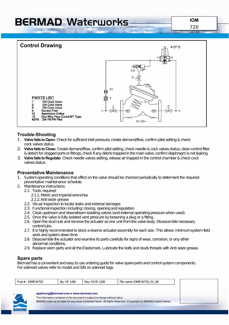
7. After the pressure is stabilized, lock the pilots locking nut and open fully the downstream isolating valve.8. The Restriction [31] enables the 2-Way control & reduces valve closing speed.9. The One Way Flow Control [19] is factory set fully open. To decrease opening speed or to stabilize the valve
reaction, turn the needle valve CW.10. Calibrating Pressure Reducing Systems that include parallel By-Pass PR Valves, require calibrating each of
the PR Valves separately, while the parallel PR Valve/s is closed. Calibration should refer to a sharedpressure gauge, installed downstream from the system. For best & long term performance, set larger PRV to0.5 bar lower than smaller PRV.
11. Relief Valves should be set 1 bar above system highest set-pressure.
7/27/2019 Ww Mun Iom 720 English
http://slidepdf.com/reader/full/ww-mun-iom-720-english 2/2
IOM
720
Trouble-Shooting1. Valve fails to Open: Check for sufficient inlet pressure, create demand/flow, confirm pilot setting & check
cock valves status. 2. Valve fails to Close: Create demand/flow, confirm pilot setting, check needle & cock valves status, clean control filter
& detect for clogged ports or fittings, check if any debris trapped in the main valve, confirm diaphragm is not leaking.
3. Valve fails to Regulate: Check needle valves setting, release air trapped in the control chamber & check cockvalves status.
Preventative Maintenance1. System operating conditions that effect on the valve should be checked periodically to determent the required
preventative maintenance schedule.2. Maintenance instructions:
2.1. Tools required:2.1.1. Metric and imperial wrenches2.1.2. Anti seize grease
2.2. Visual inspection to locate leaks and external damages2.3. Functional inspection including: closing, opening and regulation.2.4. Close upstream and downstream isolating valves (and external operating pressure when used).2.5. Once the valve is fully isolated vent pressure by loosening a plug or a fitting.2.6. Open the stud nuts and remove the actuator as one unit from the valve body. Disassemble necessary
control tubs.2.7. It is highly recommended to stock a reserve actuator assembly for each size. This allows minimum system fieldwork and system down time.
2.8. Disassemble the actuator and examine its parts carefully for signs of wear, corrosion, or any otherabnormal conditions.
2.9. Replace worn parts and all the Elastomers. Lubricate the bolts and studs threads with Anti seize grease.
Spare partsBermad has a convenient and easy to use ordering guide for valve spare-parts and control system components.For solenoid valves refer to model and S/N on solenoid tags. Pub #: IOMEW720 By: YE 1/08 Rev: 01YE-1/08 File name: IOMEW720_01_08
[email protected]● www.bermad.com
The information contained in this document is subject to change without notice.
BERMAD shall not be liable for any errors contained herein. All Rights Reserved. ©Copyright by BERMAD Control Valves.
Control Drawing