wt1600 digital power meter communication interface user's manual · 2014-03-26 · this...
TRANSCRIPT

Digital Power MeterCommunication Interface
IM 760101-11E4th Edition
iIM 760101-11E
IntroductionThank you for purchasing YOKOGAWA’s WT1600 Digital Power Meter.
This Communication Interface User’s Manual describes the functions and commands ofthe GP-IB and serial interfaces. To ensure proper use of the GP-IB/serial/Ethernetinterfaces, please read this manual thoroughly.
Keep the manual in a safe place for quick reference whenever a question arises.Two manuals are provided with the WT1600 including this Communication InterfaceUser’s Manual.
Manual Name Manual No. Description
WT1600 Digital Power Meter IM 760101-01E Describes all functions except for theUser’s Manual communications functions and operation
procedures of the instrument.
WT1600 Digital Power Meter IM 760101-11E Describes the communications functions ofCommunication User’s Manual the GP-IB/serial/Ethernet interface.
Note• The contents of this manual are subject to change without prior notice as a result of
improvements in instrument’s performance and functions.
• Every effort has been made in the preparation of this manual to ensure the accuracyof its contents. However, should you have any questions or find any errors, pleasecontact your nearest YOKOGAWA dealer.
• Copying or reproduction of all or any part of the contents of this manual withoutYOKOGAWA’s permission is strictly prohibited.
Trademarks• MS-DOS, and Visual Basic are either registered trademarks or trademarks of
Microsoft Corporation in the United States and/or other countries.
• Adobe, Adobe Acrobat, and PostScript are trademarks or registered trademarks ofAdobe Systems Incorporated.
• For purposes of this manual, the TM and symbols do not accompany their
respective trademark names or registered trademark names.• Other product names are trademarks or registered trademarks of their respective
holders.
Revisions1st Edition: June 2001
2nd Edition: August 20013rd Edition: December 20024th Edition: April 2004
4th Edition: April (YK)
All Rights Reserved, Copyright © 2001 Yokogawa Electric Corporation
ii IM 760101-11E
How to Use this Manual
Structure of this ManualThis User’s Manual consists of seven chapters, an Appendix and an Index as described
below.
Chapter 1 Overview of the GP-IB InterfaceDescribes the functions and specifications of GP-IB.
Chapter 2 Overview of the Serial InterfaceDescribes the functions and specifications of serial.
Chapter 3 Overview of the Ethernet InterfaceDescribes the functions and specifications of Ethernet.
Chapter 4 Before ProgrammingDescribes formats used when sending a command.
Chapter 5 CommandDescribes each command.
Chapter 6 Status ReportDescribes the status byte, various registers and queues.
Chapter 7 Sample ProgramsSample programs, written in Visual Basic, for MS-DOS/V machines
equipped with the following GP-IB board: AT-GPIB/TNT IEEE-488.2, fromNational Instruments.
AppendixContains references including the ASCII character code table.
IndexProvides an alphabetically ordered index.
Conventions Used in this Manual• Symbols used for Notes and Keys
Type Symbol Description
Unitk 1000 e.g.: 100 kS/s (sample rate)K 1024 e.g.: 640 KB (floppy disk memory capacity)
Note Note Provides information that is necessary for proper operation of theinstrument.
Key Communication Refers to a soft key displayed on the screen.
• Symbols used in syntax descriptionsSymbols which are used in the syntax descriptions in Chapter 5 are shown below.
These symbols are referred to as
Symbol Description Example Example of Input
<> Defined value ELEMent<x> <x>=1 to 6 -> ELEMENT2
{} One of the options in {} is selected. HCOPy:{TIFF|BMP} -> HCOPy:TIFF?
| Exclusive OR
[] Abbreviated CURSor[:TYPE] -> CURSor
iiiIM 760101-11E
Contents
Introduction ................................................................................................................................... iHow to Use this Manual ................................................................................................................ ii
Chapter 1 Overview of the GP-IB Interface1.1 Names of the Parts and Their Functions ....................................................................... 1-1
1.2 Connecting the GP-IB Cable ......................................................................................... 1-21.3 GP-IB Interface Functions ............................................................................................. 1-31.4 GP-IB Interface Specifications ....................................................................................... 1-4
1.5 Setting the Address ........................................................................................................ 1-51.6 Response to Interface Messages .................................................................................. 1-6
Chapter 2 Overview of the Serial Interface2.1 Names of the Parts and Their Functions ....................................................................... 2-12.2 Serial Interface Functions and Specifications ................................................................ 2-2
2.3 Connecting the Serial Interface Cable ........................................................................... 2-32.4 Handshaking .................................................................................................................. 2-52.5 Matching the Data Format ............................................................................................. 2-7
2.6 Setting Serial Communications ...................................................................................... 2-8
Chapter 3 Overview of the Ethernet Interface3.1 Names of the Parts and Their Functions ....................................................................... 3-13.2 Ethernet Interface Functions and Specifications ........................................................... 3-23.3 Connecting the WT to a PC ........................................................................................... 3-3
Chapter 4 Before Programming4.1 Messages ...................................................................................................................... 4-1
4.2 Commands ..................................................................................................................... 4-34.3 Response ....................................................................................................................... 4-54.4 Data ............................................................................................................................... 4-5
4.5 Synchronization with the Controller ............................................................................... 4-7
Chapter 5 Commands5.1 Command List ................................................................................................................ 5-15.2 AOUTput Group ........................................................................................................... 5-125.3 COMMunicate Group ................................................................................................... 5-14
5.4 CURSor Group ............................................................................................................ 5-175.5 DISPlay Group ............................................................................................................. 5-205.6 FILE Group .................................................................................................................. 5-33
5.7 HARMonics Group ....................................................................................................... 5-385.8 HCOPy Group .............................................................................................................. 5-405.9 HOLD Group ................................................................................................................ 5-45
5.10 IMAGe Group ............................................................................................................... 5-455.11 INPut Group ................................................................................................................. 5-465.12 INTEGrate Group ......................................................................................................... 5-54
5.13 MEASure Group .......................................................................................................... 5-585.14 MOTor Group ............................................................................................................... 5-625.15 NUMeric Group ............................................................................................................ 5-66
5.16 RATE Group ................................................................................................................ 5-735.17 STATus Group .............................................................................................................. 5-73
1
2
3
4
5
6
7
App
Index
iv IM 760101-11E
Contents
5.18 STORe Group .............................................................................................................. 5-755.19 SYSTem Group ............................................................................................................ 5-805.20 WAVeform Group ......................................................................................................... 5-83
5.21 WSETup (Wave SETup) Group ................................................................................... 5-855.22 Common Command Group.......................................................................................... 5-88
Chapter 6 Status Report6.1 Overview of the Status Report ....................................................................................... 6-16.2 Status Byte ..................................................................................................................... 6-2
6.3 Standard Event Register ................................................................................................ 6-36.4 Extended Event Register ............................................................................................... 6-46.5 Output Queue and Error Queue..................................................................................... 6-5
Chapter 7 Sample Program7.1 Before Programming ...................................................................................................... 7-1
7.2 Sample Program Image ................................................................................................. 7-27.3 Initialization, Error, and Functions for Execution............................................................ 7-37.4 Output of Normal Measurement Data ............................................................................ 7-6
7.5 Output of Harmonic Measurement Data ...................................................................... 7-107.6 Output of Waveform Data (ASCII Format) ................................................................... 7-147.7 Output of Waveform Data (FLOAT Format) ................................................................. 7-17
AppendixAppendix 1 ASCII Character Code ....................................................................................App-1
Appendix 2 Error Messages ..............................................................................................App-2Appendix 3 Overview of IEEE 488.2-1987 ........................................................................App-4
Index
Overview
of th
e GP
-IB In
terface
1-1IM 7601010-11E
1
Chapter 1 Overview of the GP-IB Interface
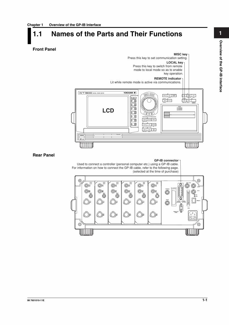
1.1 Names of the Parts and Their Functions
Front Panel
LCD
RESET SELECT
DIGITAL POWER METER
INPUT
MOTOR SET
CAL
RANGE
FILTER
START STOPSYNC SRC
AVG MEASURE
SCALING
SINGLE STORE SET
REMOTE
MAX HOLD NULL
MENU
HARMONICS
TRIG'D
CURSOR
DISPLAY FILE
LOCAL
PUSH
MISC
SHIFT
COPYSTORE
WAVE
HOLDUPDATE
RATE
WIRING
INTEGRATOR
INTEG SET RESET
POWER
ESC
REMOTE indicatorLit while remote mode is active via communications.
LOCAL keyPress this key to switch from remote mode to local mode so as to enable
key operation.
MISC keyPress this key to set communication setting.
Rear PanelGP-IB connector
Used to connect a controller (personal computer etc.) using a GP-IB cable.For information on how to connect the GP-IB cable, refer to the following page.
(selected at the time of purchase)
EXT CLK
START
TXD
LINK
10Base-T
SCSI
orGP-IB(IEEE488)
SERIAL(RS-232)
VIDEO-OUT
TORQUE
EXT
I
U
EXT
I
U
EXT
I
U
EXT
I
U
EXT
I
U
EXT
I
U
D/A OUTPUT
SPEED
(VGA)
STOP
654321
1-2 IM 760101-11E
1.2 Connecting the GP-IB Cable
GP-IB CableThe GP-IB connector on the side panel of the PZ4000 is a 24-pin connector that
conforms to IEEE Standard 488-1978. Use a GP-IB cable that also conforms to IEEEStandard 488-1978.
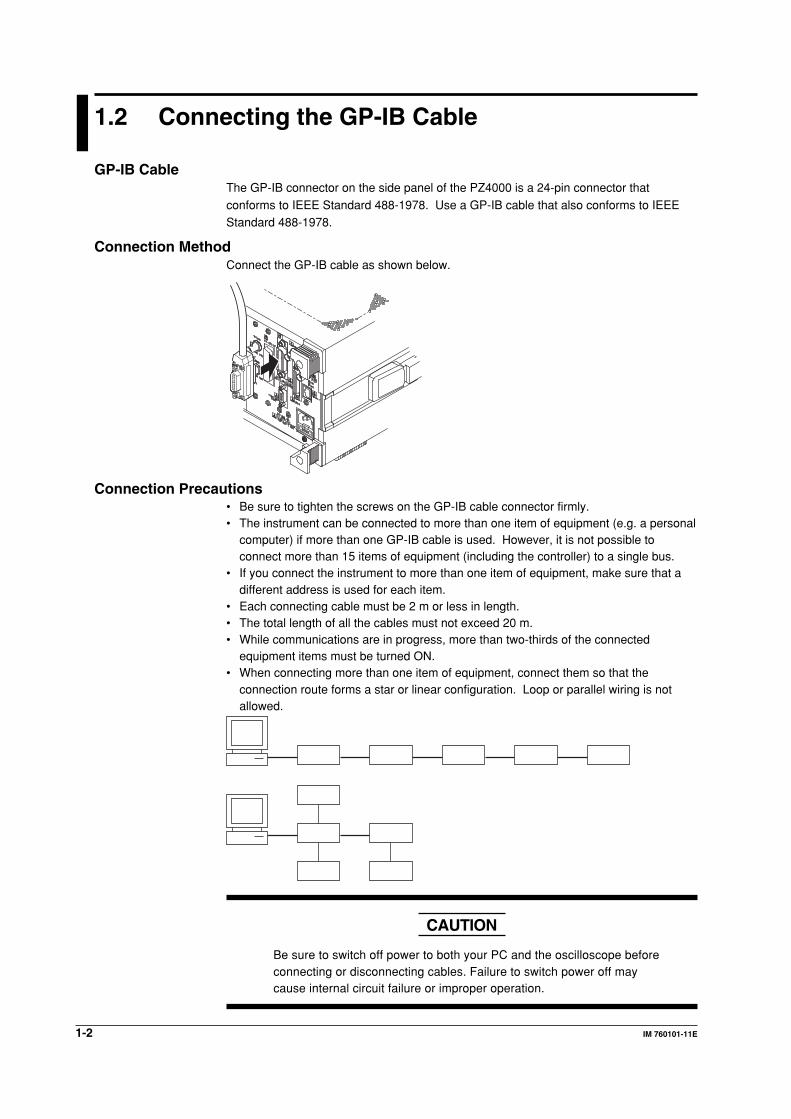
Connection MethodConnect the GP-IB cable as shown below.
Connection Precautions• Be sure to tighten the screws on the GP-IB cable connector firmly.• The instrument can be connected to more than one item of equipment (e.g. a personal
computer) if more than one GP-IB cable is used. However, it is not possible toconnect more than 15 items of equipment (including the controller) to a single bus.
• If you connect the instrument to more than one item of equipment, make sure that adifferent address is used for each item.
• Each connecting cable must be 2 m or less in length.• The total length of all the cables must not exceed 20 m.• While communications are in progress, more than two-thirds of the connected
equipment items must be turned ON.• When connecting more than one item of equipment, connect them so that the
connection route forms a star or linear configuration. Loop or parallel wiring is notallowed.
CAUTION
Be sure to switch off power to both your PC and the oscilloscope beforeconnecting or disconnecting cables. Failure to switch power off maycause internal circuit failure or improper operation.
Overview
of th
e GP
-IB In
terface
1-3IM 7601010-11E
11.3 GP-IB Interface Functions
GP-IB Interface FunctionsListener function• Allows you to make the settings which you can make using the panel keys on the
instrument, except for the power ON/OFF and GP-IB communications settings.• Receives commands from a controller requesting output of set-up and waveform data.
Also receives status report commands.
Talker function• Outputs set-up and waveform data.
NoteThe talk-only, listen-only and controller functions are not available on this instrument.
Switching between Remote and Local ModesWhen switched from Local to Remote ModeRemote mode is activated when a REN (Remote Enable) message is received from a
controller while local mode is active.
• REMOTE is displayed on.
• All front panel keys except the LOCAL can no longer be operated any more.• Settings entered in local mode are retained.
When switched from Remote to Local ModePressing the LOCAL in remote mode puts the instrument in local mode. However, this isnot possible if Local Lockout has been set by the controller (page 1-6).
• The REMOTE indicator is turned off.• All front panel keys are operative.
• Settings entered in remote mode are retained.
1-4 IM 760101-11E
1.4 GP-IB Interface Specifications
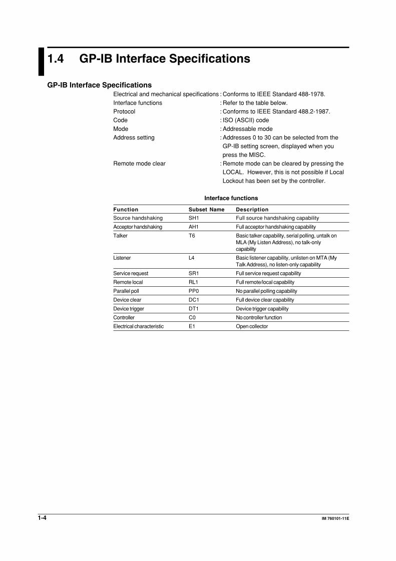
GP-IB Interface SpecificationsElectrical and mechanical specifications : Conforms to IEEE Standard 488-1978.
Interface functions : Refer to the table below.Protocol : Conforms to IEEE Standard 488.2-1987.Code : ISO (ASCII) code
Mode : Addressable modeAddress setting : Addresses 0 to 30 can be selected from the
GP-IB setting screen, displayed when you
press the MISC.Remote mode clear : Remote mode can be cleared by pressing the
LOCAL. However, this is not possible if Local
Lockout has been set by the controller.
Interface functions
Function Subset Name Description
Source handshaking SH1 Full source handshaking capability
Acceptor handshaking AH1 Full acceptor handshaking capability
Talker T6 Basic talker capability, serial polling, untalk onMLA (My Listen Address), no talk-onlycapability
Listener L4 Basic listener capability, unlisten on MTA (MyTalk Address), no listen-only capability
Service request SR1 Full service request capability
Remote local RL1 Full remote/local capability
Parallel poll PP0 No parallel polling capability
Device clear DC1 Full device clear capability
Device trigger DT1 Device trigger capability
Controller C0 No controller function
Electrical characteristic E1 Open collector
Overview
of th
e GP
-IB In
terface
1-5IM 7601010-11E
11.5 Setting the Address
Keys
RESET SELECT
INPUT
MOTOR SET
RANGE
FILTER
START STOP SYNC SRC
AVG
SCALING
SINGLE STORE SET
REMOTE
MAX HOLD NULL
MENU
HARMONICS
TRIG'D
CURSOR
DISPLAY FILE
LOCAL MISC
SHIFT
COPYSTORE
WAVE
HOLD UP DATERATE
WIRING
INTEGRATOR
INTEG SET RESET
To exit the menu during operation, press ESC.
ESC
MEASURE
CAL
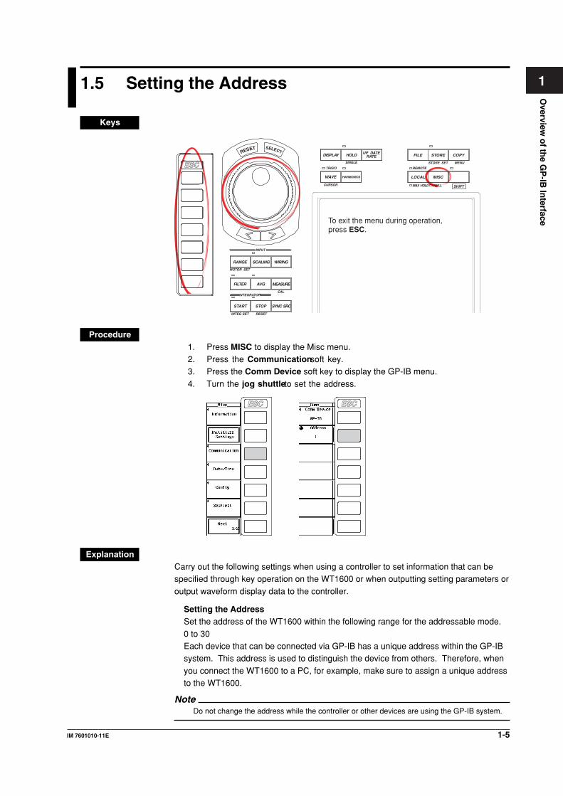
Procedure1. Press MISC to display the Misc menu.2. Press the Communication soft key.3. Press the Comm Device soft key to display the GP-IB menu.
4. Turn the jog shuttle to set the address.
ESC ESC
ExplanationCarry out the following settings when using a controller to set information that can bespecified through key operation on the WT1600 or when outputting setting parameters or
output waveform display data to the controller.
Setting the AddressSet the address of the WT1600 within the following range for the addressable mode.
0 to 30Each device that can be connected via GP-IB has a unique address within the GP-IBsystem. This address is used to distinguish the device from others. Therefore, when
you connect the WT1600 to a PC, for example, make sure to assign a unique addressto the WT1600.
NoteDo not change the address while the controller or other devices are using the GP-IB system.
1-6 IM 760101-11E
1.6 Response to Interface Messages
Response to Interface MessagesResponse to a uni-line messageIFC (Interface Clear)Clears the talker and listener. Stops output if data is being output.
REN (Remote Enable)Switches between remote and local modes.
IDY (Identify) is not supported.
Response to a multi-line message (address command)GTL (Go To Local)Switches to local mode.
SDC (Selected Device Clear)Clears the program message (command) which is currently being output. Also clears theoutput queue (page 6-5).
*OPC and *OPC? will be disabled if they are currently being executed.*WAI and COMMunicate:WAIT will be stopped immediately.
GET (Group Execute Trigger)Operates in the sameway as the TRG command.
PPC (Parallel Poll Configure) and TCT (Take Control) are not supported
Response to a multi-line message (universal command)LLO (Local Lockout)Invalidates the LOCAL on the front panel to disable switching to local mode.
DCL (Device Clear)Same as SDC
SPE (Serial Poll Enable)Sets the talker function to serial poll mode for all equipment connected to thecommunications bus. The controller performs polling on equipment sequentially.
SPD (Serial Poll Disable)Clears serial poll mode as the talker function for all equipment connected to thecommunications bus.
PPU (Parallel Poll Unconfigure) is not supported.
What is an Interface Message?An interface message is also called an interface command or bus command, and isissued by the controller. Interface messages are classified as follows.
Uni-line messagesMessages are transferred through a single control line. The following three types of uni-line message are available.
IFC (Interface Clear)REN (Remote Enable)IDY (Identify)
Overview
of th
e GP
-IB In
terface
1-7IM 7601010-11E
1
1.6 Response to Interface Messages
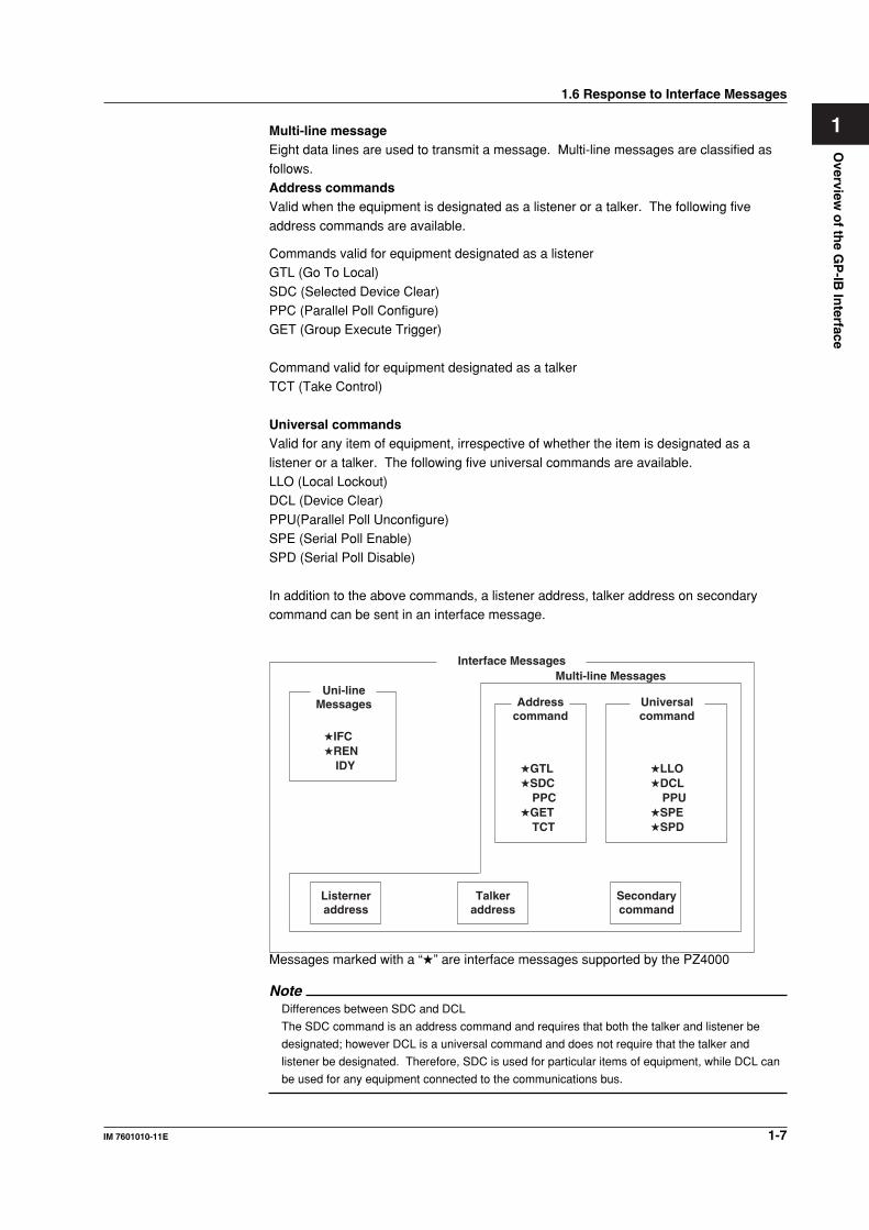
Multi-line messageEight data lines are used to transmit a message. Multi-line messages are classified as
follows.Address commandsValid when the equipment is designated as a listener or a talker. The following five
address commands are available.
Commands valid for equipment designated as a listenerGTL (Go To Local)
SDC (Selected Device Clear)PPC (Parallel Poll Configure)GET (Group Execute Trigger)
Command valid for equipment designated as a talkerTCT (Take Control)
Universal commandsValid for any item of equipment, irrespective of whether the item is designated as a
listener or a talker. The following five universal commands are available.LLO (Local Lockout)DCL (Device Clear)
PPU(Parallel Poll Unconfigure)SPE (Serial Poll Enable)SPD (Serial Poll Disable)
In addition to the above commands, a listener address, talker address on secondarycommand can be sent in an interface message.
Interface Messages
Uni-lineMessages Address
commandUniversalcommand
★IFC★REN
IDY ★GTL★SDC
PPC★GET
TCT
★LLO★DCL
PPU★SPE★SPD
Listerneraddress
Talkeraddress
Secondarycommand
Multi-line Messages
Messages marked with a “★” are interface messages supported by the PZ4000
NoteDifferences between SDC and DCL
The SDC command is an address command and requires that both the talker and listener be
designated; however DCL is a universal command and does not require that the talker and
listener be designated. Therefore, SDC is used for particular items of equipment, while DCL can
be used for any equipment connected to the communications bus.
Overview
of th
e Serial In
terface
2-1IM 760101-11E
2
Chapter 2 Overview of the Serial Interface
2.1 Names of the Parts and Their Functions
Front Panel
LCD
RESET SELECT
DIGITAL POWER METER
INPUT
MOTOR SET
CAL
RANGE
FILTER
START STOPSYNC SRC
AVG MEASURE
SCALING
SINGLE STORE SET
REMOTE
MAX HOLD NULL
MENU
HARMONICS
TRIG'D
CURSOR
DISPLAY FILE
LOCAL
PUSH
MISC
SHIFT
COPYSTORE
WAVE
HOLDUPDATE
RATE
WIRING
INTEGRATOR
INTEG SET RESET
POWER
ESC
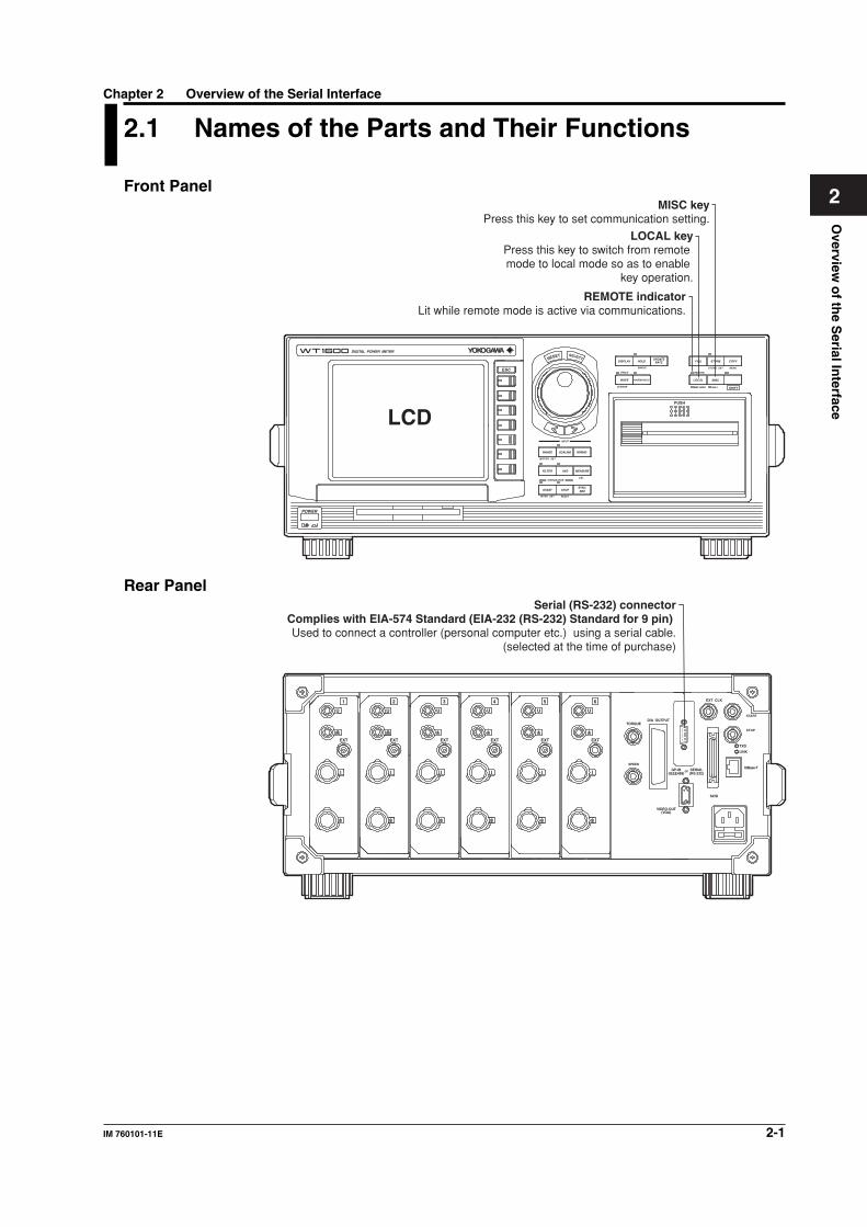
REMOTE indicatorLit while remote mode is active via communications.
LOCAL keyPress this key to switch from remote mode to local mode so as to enable
key operation.
MISC keyPress this key to set communication setting.
Rear PanelSerial (RS-232) connector
Complies with EIA-574 Standard (EIA-232 (RS-232) Standard for 9 pin) Used to connect a controller (personal computer etc.) using a serial cable.
(selected at the time of purchase)
EXT CLK
START
TXD
LINK
10Base-T
SCSI
orGP-IB(IEEE488)
SERIAL(RS-232)
VIDEO-OUT
TORQUE
EXT
I
U
EXT
I
U
EXT
I
U
EXT
I
U
EXT
I
U
EXT
I
U
D/A OUTPUT
SPEED
(VGA)
STOP
654321
2-2 IM 760101-11E
2.2 Serial Interface Functions and Specifications
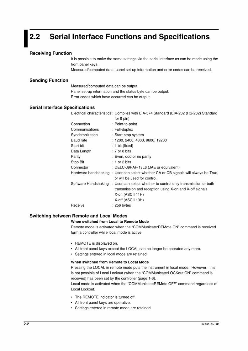
Receiving FunctionIt is possible to make the same settings via the serial interface as can be made using the
front panel keys.Measured/computed data, panel set-up information and error codes can be received.
Sending FunctionMeasured/computed data can be output.Panel set-up information and the status byte can be output.
Error codes which have occurred can be output.
Serial Interface SpecificationsElectrical characteristics : Complies with EIA-574 Standard (EIA-232 (RS-232) Standard
for 9 pin)Connection : Point-to-point
Communications : Full-duplexSynchronization : Start-stop systemBaud rate : 1200, 2400, 4800, 9600, 19200
Start bit : 1 bit (fixed)Data Length : 7 or 8 bitsParity : Even, odd or no parity
Stop Bit : 1 or 2 bitsConnector : DELC-J9PAF-13L6 (JAE or equivalent)Hardware handshaking : User can select whether CA or CB signals will always be True,
or will be used for control.Software Handshaking : User can select whether to control only transmission or both
transmission and reception using X-on and X-off signals.
X-on (ASCII 11H)X-off (ASCII 13H)
Receive : 256 bytes
Switching between Remote and Local ModesWhen switched from Local to Remote ModeRemote mode is activated when the “COMMunicate:REMote ON” command is receivedform a controller while local mode is active.
• REMOTE is displayed on.• All front panel keys except the LOCAL can no longer be operated any more.• Settings entered in local mode are retained.
When switched from Remote to Local ModePressing the LOCAL in remote mode puts the instrument in local mode. However, thisis not possible of Local Lockout (when the “COMMunicate:LOCKout ON” command is
received) has been set by the controller (page 1-6).Local mode is activated when the “COMMunicate:REMote OFF” command regardless ofLocal Lockout.
• The REMOTE indicator is turned off.• All front panel keys are operative.• Settings entered in remote mode are retained.
Overview
of th
e Serial In
terface
2-3IM 760101-11E
2
2.3 Connecting the Serial Interface Cable
When connecting this instrument to a computer, make sure that the handshakingmethod, data transmission rate and data format selected for the instrument match those
selected for the computer.For details, refer to the following pages. Also make sure that the correct interface cableis used.
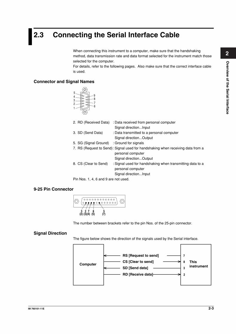
Connector and Signal Names
2 1
3 4 5
6 7 8 9
2. RD (Received Data) : Data received from personal computerSignal direction...Input
3. SD (Send Data) : Data transmitted to a personal computerSignal direction...Output
5. SG (Signal Ground) : Ground for signals
7. RS (Request to Send) : Signal used for handshaking when receiving data from apersonal computerSignal direction...Output
8. CS (Clear to Send) : Signal used for handshaking when transmitting data to apersonal computerSignal direction...Input
Pin Nos. 1, 4, 6 and 9 are not used.
9-25 Pin Connector
58723(2) (3)(4) (5) (7)
The number between brackets refer to the pin Nos. of the 25-pin connector.
Signal DirectionThe figure below shows the direction of the signals used by the Serial interface.
ComputerThis instrument
RS [Request to send]
SD [Send data]
RD [Receive data] 2
3
8
7
CS [Clear to send]
2-4 IM 760101-11E
2.3 Connecting the Serial Interface Cable
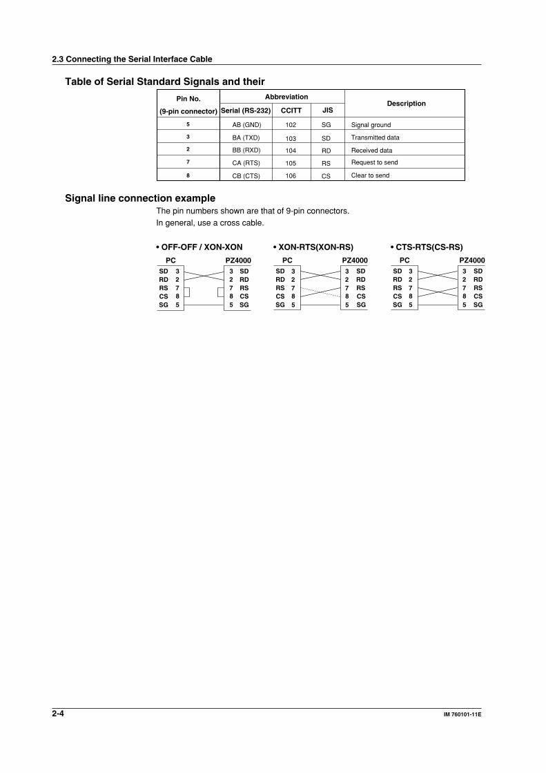
Table of Serial Standard Signals and their
Pin No.
(9-pin connector)
Abbreviation
Serial (RS-232)Description
CCITT JIS
5
3
2
8
7
AB (GND)
BA (TXD)
BB (RXD)
CB (CTS)
CA (RTS)
102 SG
103
104
106
105
SD
RD
CS
RS
Signal ground
Transmitted data
Request to send
Received data
Clear to send
Signal line connection exampleThe pin numbers shown are that of 9-pin connectors.In general, use a cross cable.
SDRDRSCSSG
SDRDRS
SG
• OFF-OFF / XON-XON
PC PZ4000SDRDRSCSSG
SDRDRS
SG
• XON-RTS(XON-RS)
PC PZ4000SDRDRSCSSG
SDRDRS
SG
• CTS-RTS(CS-RS)
PC PZ4000
CS CS CS
2 3
8 7
5
2 3
8 7
5
2 3
8 7
5
2 3
8 7
5
2 3
8 7
5
2 3
8 7
5
Overview
of th
e Serial In
terface
2-5IM 760101-11E
2
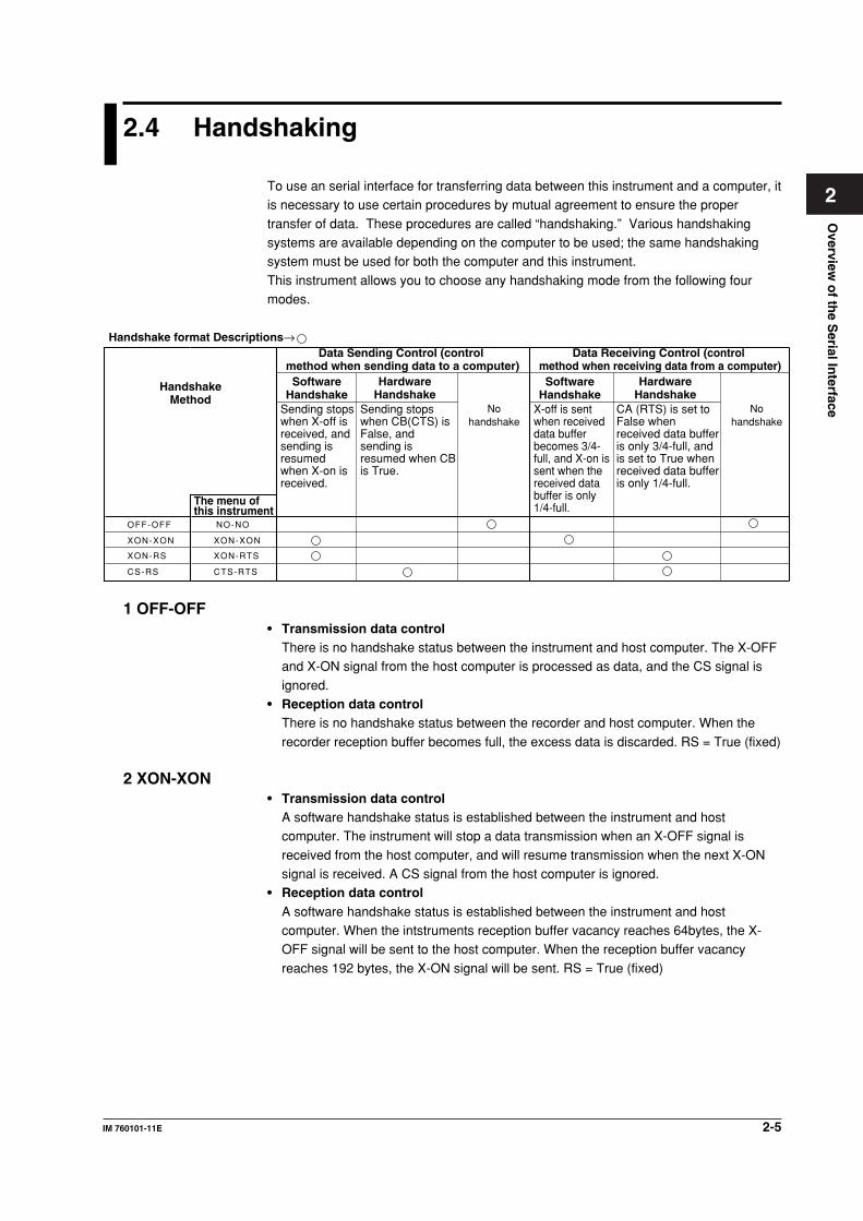
2.4 Handshaking
To use an serial interface for transferring data between this instrument and a computer, itis necessary to use certain procedures by mutual agreement to ensure the proper
transfer of data. These procedures are called “handshaking.” Various handshakingsystems are available depending on the computer to be used; the same handshakingsystem must be used for both the computer and this instrument.
This instrument allows you to choose any handshaking mode from the following fourmodes.
Data Sending Control (control method when sending data to a computer)
Data Receiving Control (control method when receiving data from a computer)
SoftwareHandshake
SoftwareHandshake
Handshake format Descriptions→
NO-NO
XON-XON
XON-RTS
CTS-RTS
HandshakeMethod
Sending stops when X-off is received, and sending is resumed when X-on is received.
Sending stops when CB(CTS) is False, and sending is resumed when CB is True.
Nohandshake
Nohandshake
X-off is sent when received data buffer becomes 3/4-full, and X-on is sent when the received data buffer is only 1/4-full.
CA (RTS) is set to False when received data buffer is only 3/4-full, and is set to True when received data buffer is only 1/4-full.
HardwareHandshake
HardwareHandshake
OFF-OFF
XON-XON
XON-RS
CS-RS
The menu of this instrument
1 OFF-OFF• Transmission data control
There is no handshake status between the instrument and host computer. The X-OFFand X-ON signal from the host computer is processed as data, and the CS signal is
ignored.• Reception data control
There is no handshake status between the recorder and host computer. When the
recorder reception buffer becomes full, the excess data is discarded. RS = True (fixed)
2 XON-XON• Transmission data control
A software handshake status is established between the instrument and hostcomputer. The instrument will stop a data transmission when an X-OFF signal is
received from the host computer, and will resume transmission when the next X-ONsignal is received. A CS signal from the host computer is ignored.
• Reception data controlA software handshake status is established between the instrument and hostcomputer. When the intstruments reception buffer vacancy reaches 64bytes, the X-OFF signal will be sent to the host computer. When the reception buffer vacancy
reaches 192 bytes, the X-ON signal will be sent. RS = True (fixed)
2-6 IM 760101-11E
2.4 Handshaking
3 XON-RS• Transmission data control
A software handshake status is established between the instrument and hostcomputer. The instrument will stop a data transmission when an X-OFF signal isreceived from the host computer, and will resume transmission when the next X-ON
signal is received. A CS signal from the host computer is ignored.• Reception data control
A hardware handshake status is established between the instrument and host
computer. When the intstruments reception buffer vacancy reaches 64bytes, an “RS =False” status will be established. When the reception buffer vacancy reaches 192bytes, an “RS = True” status will be established.
4 CS-RS• Transmission data control
A software handshake status is established between the instrument and hostcomputer. The instrument will stop a data transmission if a “CS = False” status isestablished, and will resume the transmission shen a “CS = True” status is
established. The X-OFF and X-ON signals from the host computer are processed asdata.
• Reception data controlA hardware handshake status is established between the instrument and hostcomputer. When the intstruments reception buffer vacancy reaches 64bytes, an “RS =False” status will be established. When the reception buffer vacancy reaches 192
bytes, an “RS = True” status will be established.
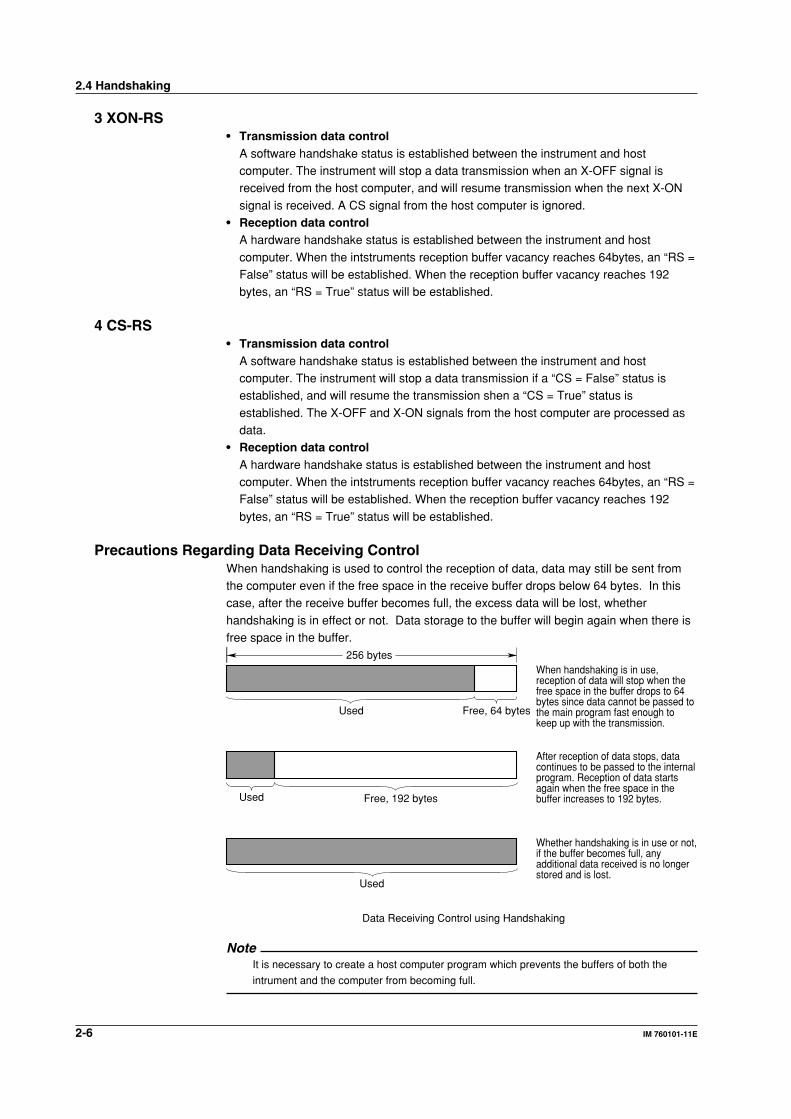
Precautions Regarding Data Receiving ControlWhen handshaking is used to control the reception of data, data may still be sent fromthe computer even if the free space in the receive buffer drops below 64 bytes. In thiscase, after the receive buffer becomes full, the excess data will be lost, whether
handshaking is in effect or not. Data storage to the buffer will begin again when there isfree space in the buffer.
256 bytes
Used Free, 64 bytes
When handshaking is in use, reception of data will stop when the free space in the buffer drops to 64 bytes since data cannot be passed to the main program fast enough to keep up with the transmission.
Used Free, 192 bytes
After reception of data stops, data continues to be passed to the internal program. Reception of data starts again when the free space in the buffer increases to 192 bytes.
Used
Whether handshaking is in use or not, if the buffer becomes full, any additional data received is no longer stored and is lost.
Data Receiving Control using Handshaking
NoteIt is necessary to create a host computer program which prevents the buffers of both the
intrument and the computer from becoming full.
Overview
of th
e Serial In
terface
2-7IM 760101-11E
2
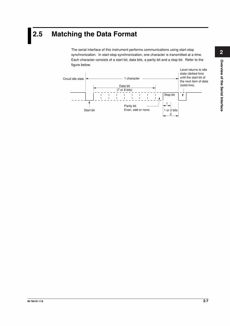
2.5 Matching the Data Format
The serial interface of this instrument performs communications using start-stopsynchronization. In start-stop synchronization, one character is transmitted at a time.
Each character consists of a start bit, data bits, a parity bit and a stop bit. Refer to thefigure below.
Data bit(7 or 8 bits)
1 character
Stop bit
1
1 or 2 bits2
Parity bitEven, odd or noneStart bit
Circuit idle state
Level returns to idlestate (dotted line)until the start bit ofthe next item of data(solid line).
2-8 IM 760101-11E
2.6 Setting Serial Communications
Keys
RESET SELECT
INPUT
MOTOR SET
RANGE
FILTER
START STOP SYNC SRC
AVG
SCALING
SINGLE STORE SET
REMOTE
MAX HOLD NULL
MENU
HARMONICS
TRIG'D
CURSOR
DISPLAY FILE
LOCAL MISC
SHIFT
COPYSTORE
WAVE
HOLD UP DATERATE
WIRING
INTEGRATOR
INTEG SET RESET
To exit the menu during operation, press ESC.
ESC
MEASURE
CAL
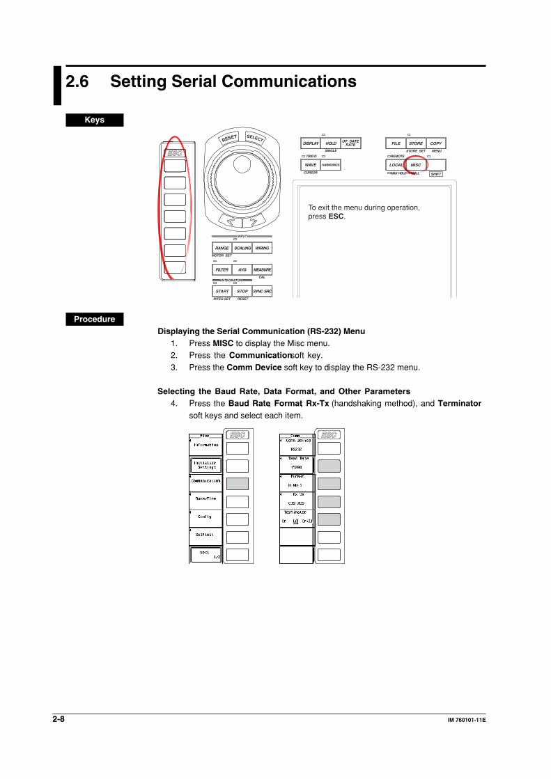
ProcedureDisplaying the Serial Communication (RS-232) Menu
1. Press MISC to display the Misc menu.2. Press the Communication soft key.
3. Press the Comm Device soft key to display the RS-232 menu.
Selecting the Baud Rate, Data Format, and Other Parameters4. Press the Baud Rate, Format, Rx-Tx (handshaking method), and Terminator
soft keys and select each item.
ESC ESC
Overview
of th
e Serial In
terface
2-9IM 760101-11E
2
ExplanationCarry out the following settings when using a controller to set information that can bespecified through key operation on the WT1600 or when outputting setting parameters oroutput waveform data to the controller.
Selecting the Baud RateSelect the baud rate from the following.1200, 2400, 4800, 9600, and 19200
Selecting the Data FormatSelect the combination of data length, parity, and stop bit from the following.
8-NO-1, 7-EVEN-1, 7-ODD-1, and 7-NO-2
Selecting the Handshaking MethodSelect the transmit data control and receive data control from the following.NO-NO, XON-XON, XON-RTS, and CTS-RTS
Selecting the TerminatorSelect the terminator from the following. The menu of the WT1600 selects theterminator that is used when transmitting data from the WT1600. Use “Lf” or “Cr+Lf”
for the terminator when receiving the data on the WT1600.Cr, Lf, and Cr+Lf
2.6 Setting Serial Communications
Overview
of th
e Eth
ernet In
terface
3-1IM 760101-11E
3
Chapter 3 Overview of the Ethernet Interface
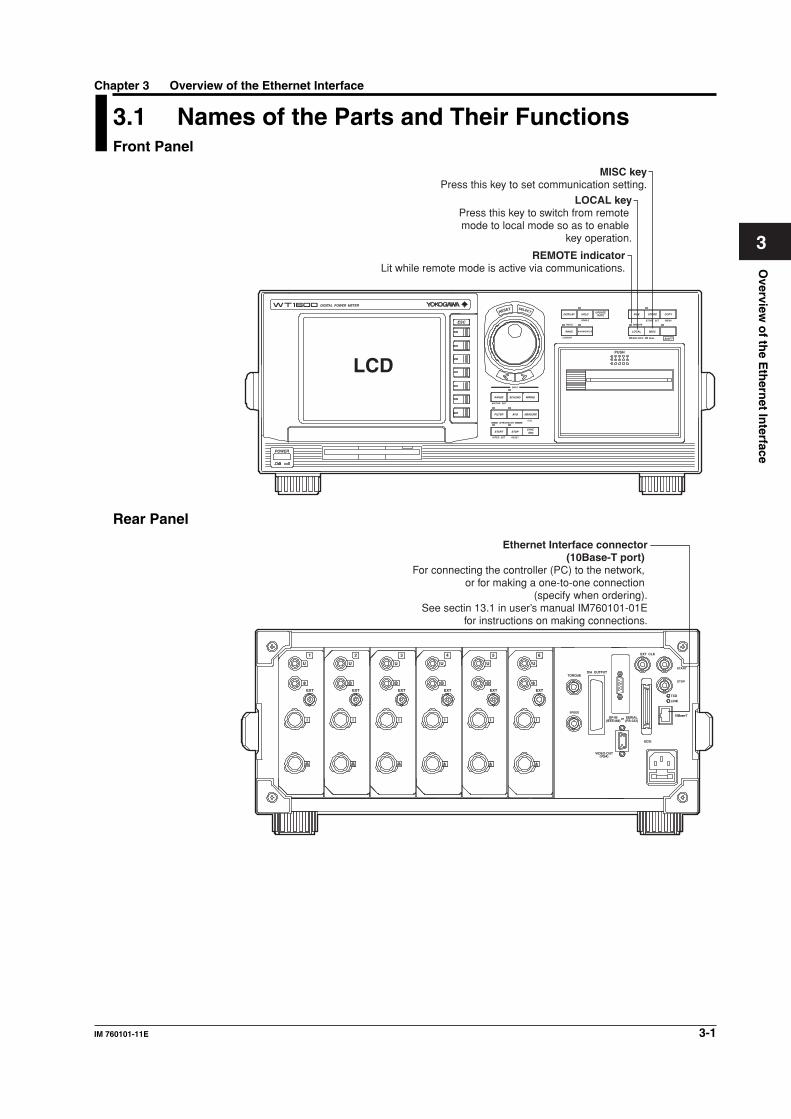
3.1 Names of the Parts and Their FunctionsFront Panel
LCD
RESET SELECT
DIGITAL POWER METER
INPUT
MOTOR SET
CAL
RANGE
FILTER
START STOPSYNC SRC
AVG MEASURE
SCALING
SINGLE STORE SET
REMOTE
MAX HOLD NULL
MENU
HARMONICS
TRIG'D
CURSOR
DISPLAY FILE
LOCAL
PUSH
MISC
SHIFT
COPYSTORE
WAVE
HOLDUPDATE
RATE
WIRING
INTEGRATOR
INTEG SET RESET
POWER
ESC
REMOTE indicatorLit while remote mode is active via communications.
LOCAL keyPress this key to switch from remote mode to local mode so as to enable
key operation.
MISC keyPress this key to set communication setting.
Rear Panel
Ethernet Interface connector (10Base-T port)
For connecting the controller (PC) to the network, or for making a one-to-one connection
(specify when ordering).See sectin 13.1 in user’s manual IM760101-01E
for instructions on making connections.
EXT CLK
START
TXD
LINK
10Base-T
SCSI
orGP-IB(IEEE488)
SERIAL(RS-232)
VIDEO-OUT
TORQUE
EXT
I
U
EXT
I
U
EXT
I
U
EXT
I
U
EXT
I
U
EXT
I
U
D/A OUTPUT
SPEED
(VGA)
STOP
654321
3-2 IM 760101-11E
3.2 Ethernet Interface Functions andSpecifications
When using a WT1600 with ROM version 2.01 or later, you can control the WT from a
PC using Ethernet communications. Details about specific functions and how to entersettings are provided below.
Receiving FunctionYou can specify the same settings as those specified by front panel key operations.Receives output requests for measured and computed data, setting parameters of the
panel, and error codes.
Sending FunctionMeasured/computed data can be output.Panel setup information and the status byte can be output.Error codes which have occurred can be output.
Ethernet Interface SpecificationsElectrical and Mechanical Specifications: IEEE802.3 Compliant
No. of simultaneous connections: 1Port No.: 10001/tcpFor other specifications, see section 17.13, “Ethernet Interface (Option)” in the WT1600
Digital Power Meter User’s Manual (IM760101-01E).
Switching between Remote and Local ModeWhen Switched from Local to RemoteRemote mode is activated when the :COMMunicate:REMote ON command is receivedfrom a controller while local mode is active.
• The REMOTE indicator is turned on.• All front panel keys except LOCAL can no longer be operated.• Settings entered in local mode are retained even when switching to remote mode.
When Switched from Remote to Local ModePressing LOCAL in remote mode puts the instrument in local mode. However, this is not
possible when the :COMMunicate:REMote ON command is received from the computerwhile Local Lockout mode is active. Local mode is activated when the:COMMunicate:REMote OFF command is received regardless of Local Lockout.
• The REMOTE indicator is turned off.• All front panel keys are operative.• Settings entered in remote mode are retained even when switching to local mode.
NoteThe Ethernet interface cannot be used simultaneously with other communications interfaces (GP-
IB or serial (RS-232)).
User Verification FunctionYou must enter the user name and password to access the WT from a PC using theEthernet interface. The user name and password for accessing the WT can be specifiedin the User Account screen under the MISC menu. For details, see “Ethernet Control
Settings” below.
Overview
of th
e Eth
ernet In
terface
3-3IM 760101-11E
3
3.3 Connecting the WT to a PC
See section 13.1, “Connecting the WT1600 to a PC” in user’s manual IM760101-01E.
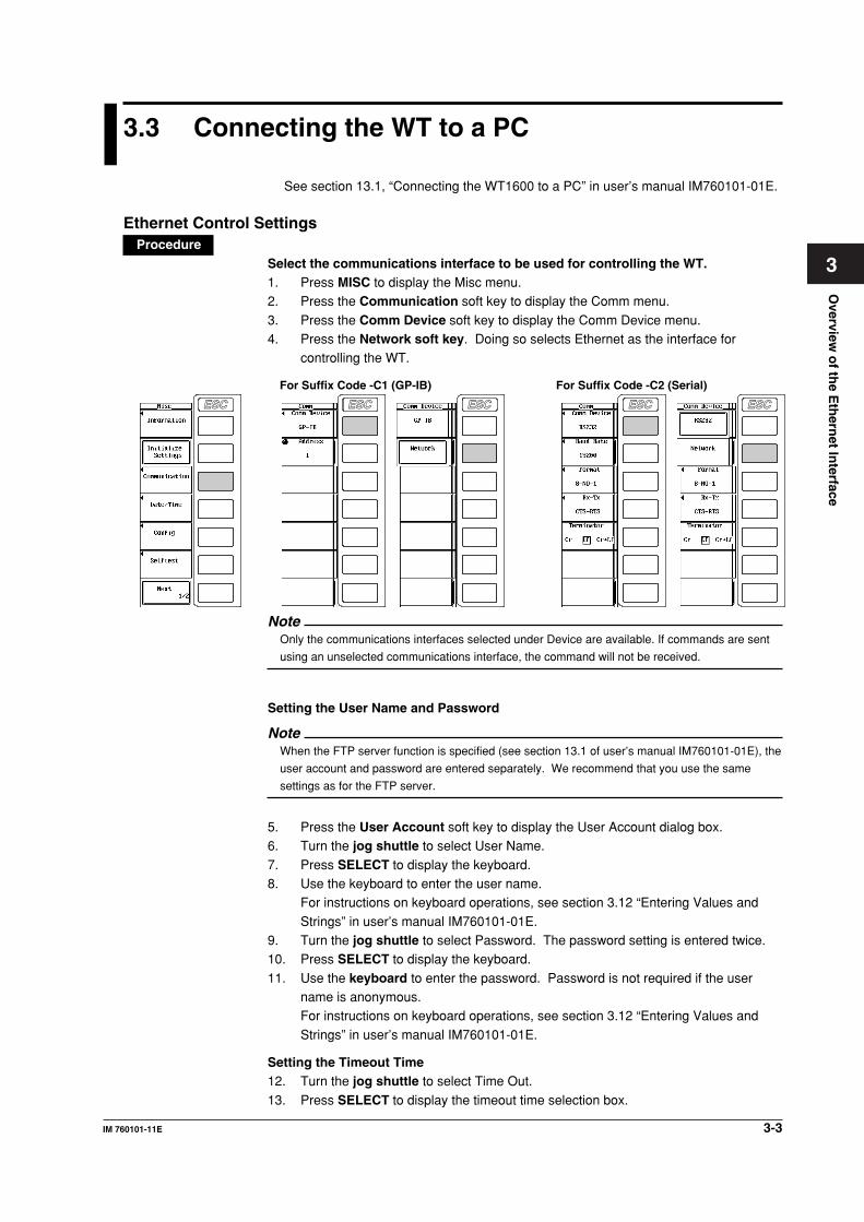
Ethernet Control SettingsProcedure
Select the communications interface to be used for controlling the WT.1. Press MISC to display the Misc menu.2. Press the Communication soft key to display the Comm menu.
3. Press the Comm Device soft key to display the Comm Device menu.4. Press the Network soft key. Doing so selects Ethernet as the interface for
controlling the WT.
ESC ESCESC ESC
For Suffix Code -C1 (GP-IB) For Suffix Code -C2 (Serial)
ESC
NoteOnly the communications interfaces selected under Device are available. If commands are sent
using an unselected communications interface, the command will not be received.
Setting the User Name and Password
NoteWhen the FTP server function is specified (see section 13.1 of user’s manual IM760101-01E), the
user account and password are entered separately. We recommend that you use the same
settings as for the FTP server.
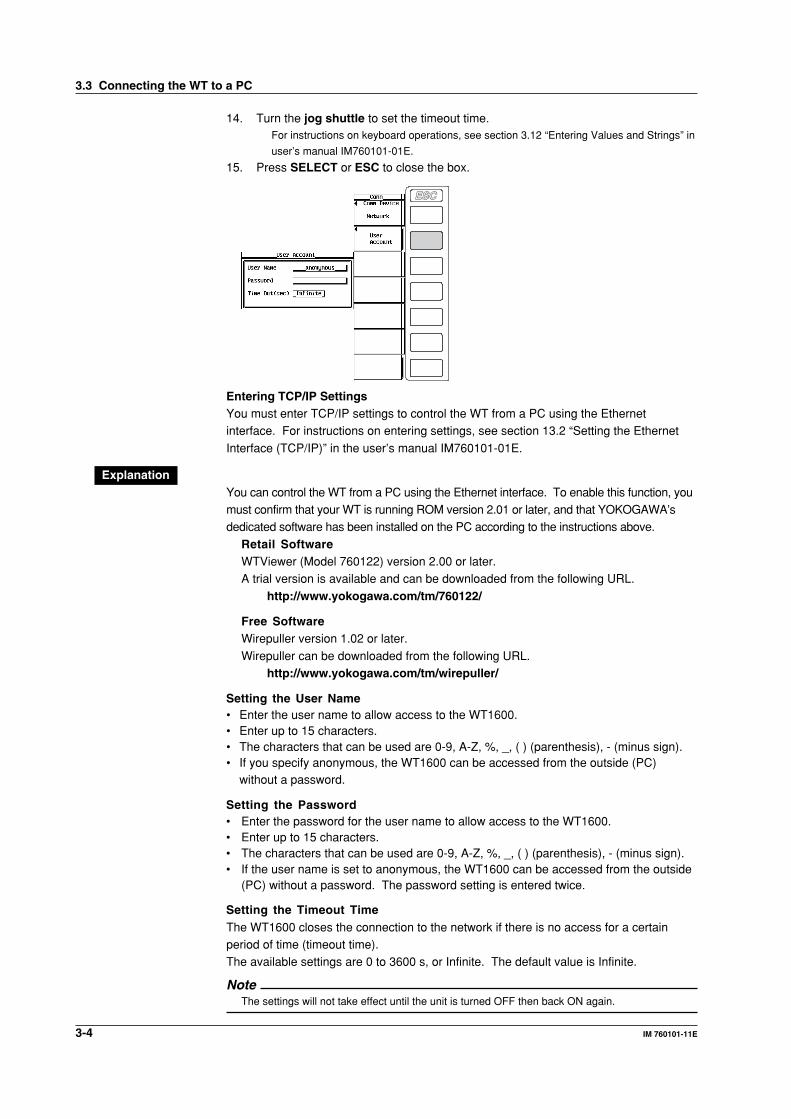
5. Press the User Account soft key to display the User Account dialog box.6. Turn the jog shuttle to select User Name.
7. Press SELECT to display the keyboard.8. Use the keyboard to enter the user name.
For instructions on keyboard operations, see section 3.12 “Entering Values and
Strings” in user’s manual IM760101-01E.9. Turn the jog shuttle to select Password. The password setting is entered twice.10. Press SELECT to display the keyboard.
11. Use the keyboard to enter the password. Password is not required if the username is anonymous.For instructions on keyboard operations, see section 3.12 “Entering Values and
Strings” in user’s manual IM760101-01E.
Setting the Timeout Time12. Turn the jog shuttle to select Time Out.
13. Press SELECT to display the timeout time selection box.
3-4 IM 760101-11E
14. Turn the jog shuttle to set the timeout time.For instructions on keyboard operations, see section 3.12 “Entering Values and Strings” in
user’s manual IM760101-01E.
15. Press SELECT or ESC to close the box.
ESC
Entering TCP/IP SettingsYou must enter TCP/IP settings to control the WT from a PC using the Ethernetinterface. For instructions on entering settings, see section 13.2 “Setting the Ethernet
Interface (TCP/IP)” in the user’s manual IM760101-01E.
ExplanationYou can control the WT from a PC using the Ethernet interface. To enable this function, youmust confirm that your WT is running ROM version 2.01 or later, and that YOKOGAWA’sdedicated software has been installed on the PC according to the instructions above.
Retail SoftwareWTViewer (Model 760122) version 2.00 or later.A trial version is available and can be downloaded from the following URL.
http://www.yokogawa.com/tm/760122/
Free SoftwareWirepuller version 1.02 or later.
Wirepuller can be downloaded from the following URL.http://www.yokogawa.com/tm/wirepuller/
Setting the User Name• Enter the user name to allow access to the WT1600.• Enter up to 15 characters.• The characters that can be used are 0-9, A-Z, %, _, ( ) (parenthesis), - (minus sign).• If you specify anonymous, the WT1600 can be accessed from the outside (PC)
without a password.
Setting the Password• Enter the password for the user name to allow access to the WT1600.• Enter up to 15 characters.• The characters that can be used are 0-9, A-Z, %, _, ( ) (parenthesis), - (minus sign).• If the user name is set to anonymous, the WT1600 can be accessed from the outside
(PC) without a password. The password setting is entered twice.
Setting the Timeout TimeThe WT1600 closes the connection to the network if there is no access for a certainperiod of time (timeout time).The available settings are 0 to 3600 s, or Infinite. The default value is Infinite.
NoteThe settings will not take effect until the unit is turned OFF then back ON again.
3.3 Connecting the WT to a PC
Befo
re Pro
gram
min
g
4-1IM 760101-11E
4
4.1 Messages
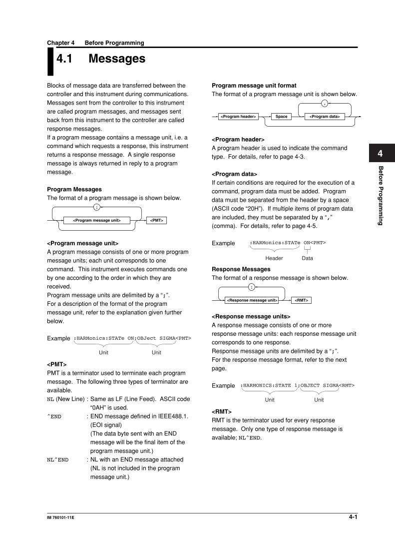
Blocks of message data are transferred between thecontroller and this instrument during communications.Messages sent from the controller to this instrument
are called program messages, and messages sentback from this instrument to the controller are calledresponse messages.
If a program message contains a message unit, i.e. acommand which requests a response, this instrumentreturns a response message. A single response
message is always returned in reply to a programmessage.
Program MessagesThe format of a program message is shown below.
<PMT>
;
<Program message unit>
<Program message unit>A program message consists of one or more programmessage units; each unit corresponds to one
command. This instrument executes commands oneby one according to the order in which they arereceived.
Program message units are delimited by a “;”.For a description of the format of the programmessage unit, refer to the explanation given further
below.
Example
Unit Unit
:HARMonics:STATe ON;OBJect SIGMA<PMT>
<PMT>PMT is a terminator used to terminate each programmessage. The following three types of terminator areavailable.
NL (New Line) : Same as LF (Line Feed). ASCII code“0AH” is used.
^END : END message defined in IEEE488.1.
(EOI signal)(The data byte sent with an ENDmessage will be the final item of the
program message unit.)NL^END : NL with an END message attached
(NL is not included in the program
message unit.)
Program message unit formatThe format of a program message unit is shown below.
,
<Program header> <Program data>Space
<Program header>A program header is used to indicate the commandtype. For details, refer to page 4-3.
<Program data>If certain conditions are required for the execution of a
command, program data must be added. Programdata must be separated from the header by a space(ASCII code “20H”). If multiple items of program data
are included, they must be separated by a “,”(comma). For details, refer to page 4-5.
Example :HARMonics:STATe ON<PMT>
Header Data
Response MessagesThe format of a response message is shown below.
<RMT>
;
<Response message unit>
<Response message units>A response message consists of one or moreresponse message units: each response message unitcorresponds to one response.
Response message units are delimited by a “;”.For the response message format, refer to the nextpage.
Example
Unit Unit
:HARMONICS:STATE 1;OBJECT SIGMA<RMT>
<RMT>RMT is the terminator used for every response
message. Only one type of response message isavailable; NL^END.
Chapter 4 Before Programming
4-2 IM 760101-11E
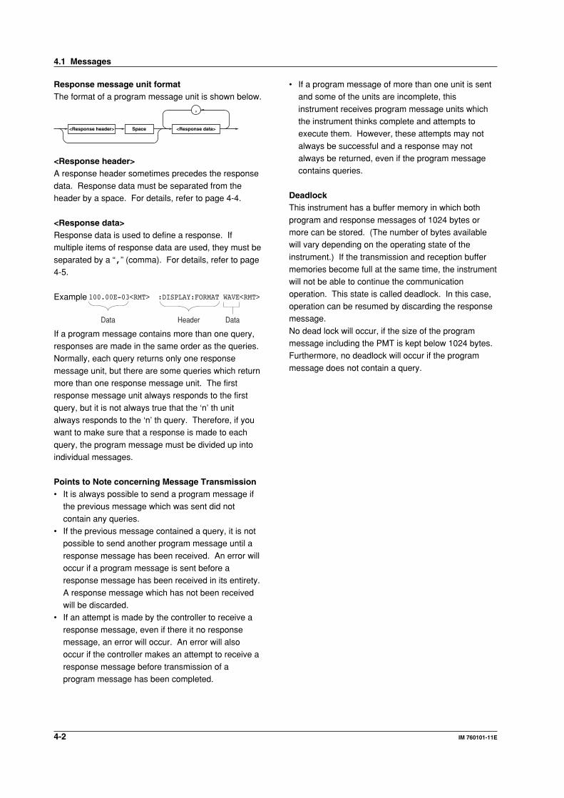
Response message unit formatThe format of a program message unit is shown below.
,
<Response header> <Response data>Space
<Response header>A response header sometimes precedes the response
data. Response data must be separated from theheader by a space. For details, refer to page 4-4.
<Response data>Response data is used to define a response. Ifmultiple items of response data are used, they must be
separated by a “,” (comma). For details, refer to page4-5.
Example 100.00E-03<RMT> :DISPLAY:FORMAT WAVE<RMT>
HeaderData Data
If a program message contains more than one query,responses are made in the same order as the queries.Normally, each query returns only one response
message unit, but there are some queries which returnmore than one response message unit. The firstresponse message unit always responds to the first
query, but it is not always true that the ‘n’ th unitalways responds to the ‘n’ th query. Therefore, if youwant to make sure that a response is made to each
query, the program message must be divided up intoindividual messages.
Points to Note concerning Message Transmission• It is always possible to send a program message if
the previous message which was sent did not
contain any queries.• If the previous message contained a query, it is not
possible to send another program message until a
response message has been received. An error willoccur if a program message is sent before aresponse message has been received in its entirety.
A response message which has not been receivedwill be discarded.
• If an attempt is made by the controller to receive a
response message, even if there it no responsemessage, an error will occur. An error will alsooccur if the controller makes an attempt to receive a
response message before transmission of aprogram message has been completed.
• If a program message of more than one unit is sentand some of the units are incomplete, this
instrument receives program message units whichthe instrument thinks complete and attempts toexecute them. However, these attempts may not
always be successful and a response may notalways be returned, even if the program messagecontains queries.
DeadlockThis instrument has a buffer memory in which both
program and response messages of 1024 bytes ormore can be stored. (The number of bytes availablewill vary depending on the operating state of the
instrument.) If the transmission and reception buffermemories become full at the same time, the instrumentwill not be able to continue the communication
operation. This state is called deadlock. In this case,operation can be resumed by discarding the responsemessage.
No dead lock will occur, if the size of the programmessage including the PMT is kept below 1024 bytes.Furthermore, no deadlock will occur if the program
message does not contain a query.
4.1 Messages
Befo
re Pro
gram
min
g
4-3IM 760101-11E
4
When Concatenating CommandsCommand GroupA command group is a group of commands which havethe same compound header. A command group maycontain sub-groups.
Example Commands relating to harmonicsmeasurement
:HARMonics?
:HARMonics:STATe
:HARMonics:OBJect
:HARMonics:PLLSource
:HARMonics:ORDer
:HARMonics:THD
:HARMonics:WIDth
When Concatenating Commands of the SameGroupThis instrument stores the hierarchical level of thecommand which is currently being executed, andperforms analysis on the assumption that the next
command to be sent will also belong to the same level.Therefore, it is possible to omit the header if thecommands belong to the same group.
Example :HARMonics:STATe ON;OBJect SIGMA
<PMT>
When Concatenating Commands of DifferentGroupsA colon (:) must be included before the header of a
command, if the command does not belong to thesame group as the preceding command.
Example :HARMonics:STATe ON;:DISPlay:
FORMat NUMeric<PMT>
When Concatenating Simple HeadersWhen you type in a simple header after anothercommand, you must include a colon (:) before thesimple header.
Example :HARMonics:STATe ON;:
HOLD ON<PMT>
When Concatenating Common CommandsCommon commands defined in IEEE 488.2-1987 areindependent of hierarchical level. Thus, it is not
necessary to add a colon (:) before a commoncommand.
Example :HARMonics:STATe ON;:*CLS;OBJect
SIGMA<PMT>
4.2 Commands
There are three types of command (program header)which can be sent from the controller to this
instrument. They differ in the format of their programheaders.
They are• Common command header• Compound header
• Simple header
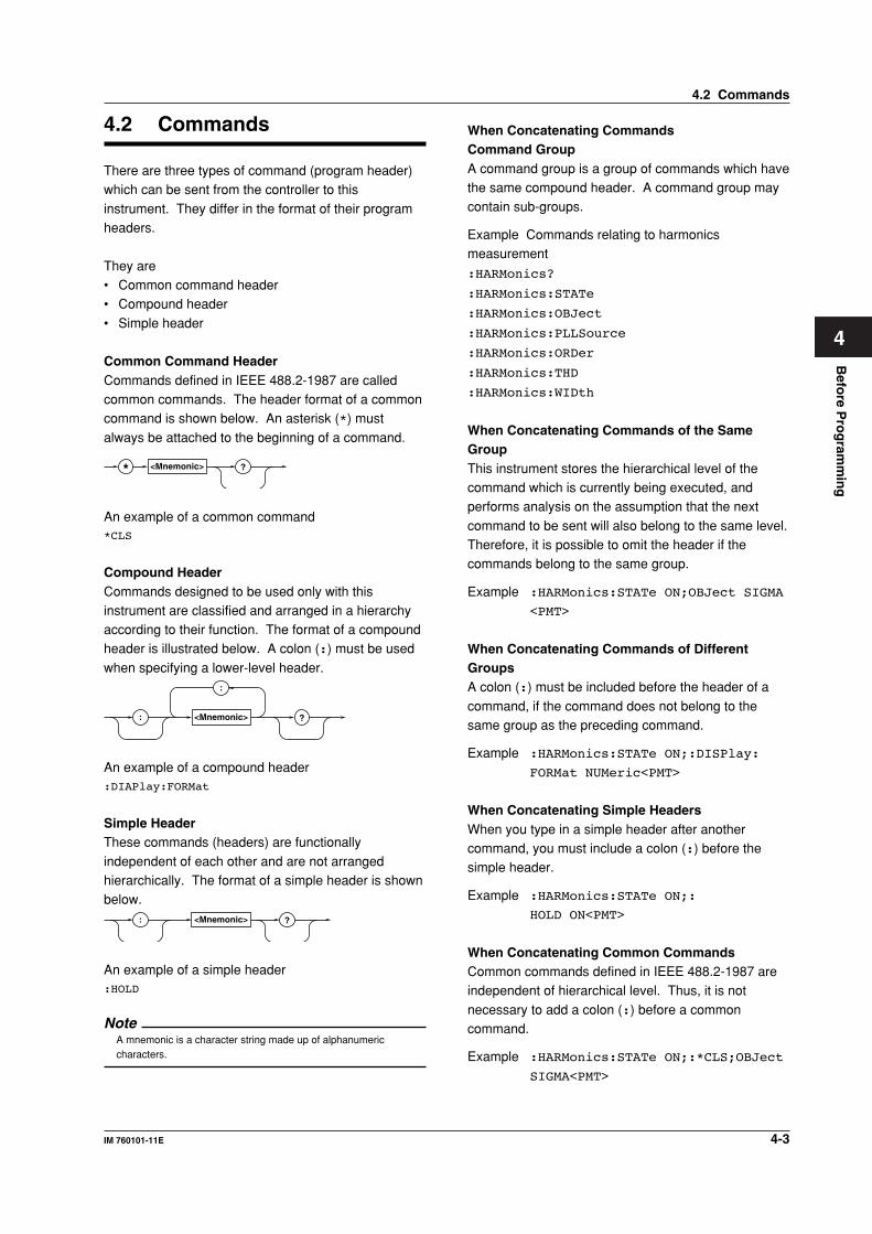
Common Command HeaderCommands defined in IEEE 488.2-1987 are calledcommon commands. The header format of a commoncommand is shown below. An asterisk (*) must
always be attached to the beginning of a command.
* <Mnemonic> ?
An example of a common command*CLS
Compound HeaderCommands designed to be used only with thisinstrument are classified and arranged in a hierarchyaccording to their function. The format of a compoundheader is illustrated below. A colon (:) must be used
when specifying a lower-level header.:
<Mnemonic> ?:
An example of a compound header:DIAPlay:FORMat
Simple HeaderThese commands (headers) are functionally
independent of each other and are not arrangedhierarchically. The format of a simple header is shownbelow.
<Mnemonic> ?:
An example of a simple header:HOLD
NoteA mnemonic is a character string made up of alphanumericcharacters.
4.2 Commands
4-4 IM 760101-11E
When Separating Commands with <PMT>If a terminator is used to separate two commands,
each command is a separate message. Therefore, thecommon header must be typed in for each commandeven when commands of the same command group
are being concatenated.
Example :HARMonics:STATe ON<PMT>:
HARMonics:OBJect SIGMA<PMT>
Upper-level QueryAn upper-level query is a compound header to which a
question mark is appended. Execution of an upper-level query allows all a group’s settings to be output atonce. Some query groups comprising more than three
hierarchical levels can output all their lower levelsettings.
Example :HARMonics?<PMT> -> :HARMONICS:
STATE 1;OBJECT SIGMA;
PLLSOURCE U1;ORDER 1,100;
THD TOTAL;WIDTH 8192<RMT>
In reply to a query, a response can be returned as aprogram message to this instrument. Transmitting aresponse can restore the settings made when the
query was executed. However, some upper-levelqueries will not return set-up data which is not currentlyin use. Note that not all a group’s information will
necessarily be sent out as a response.
Header Interpretation RulesThis instrument interprets the header receivedaccording to the following rules.
• Mnemonics are not case sensitive.
Example“CURSor” can also be written as “cursor” or“CUrsor”.
• The lower-case part of a header can be omitted.Example“CURSor” can also be written as “CURSO” or “CURS”.
• If the header ends with a question mark, thecommand is a query. It is not possible to omit thequestion mark.
Example“CURSor?” cannot be abbreviated to anythingshorter than “CURS?”.
• If the “x” at the end of a mnemonic is omitted, it isassumed to be “1”.Example
If “ELEMent<x>” is written as “ELEM”, thisrepresents “ELEMent1”.
• Any part of a command enclosed by [] can beomitted.
Example“[:INPut]:SCALing[:STATe] ON” can bewritten as
“SCALing ON”.• However, a part enclosed by [] cannot be omitted if
is located at the end of an upper-level query.
Example“SCALing?” and “SCALing:STATe?” belong todifferent upper-level query levels.
4.2 Commands
Befo
re Pro
gram
min
g
4-5IM 760101-11E
4
4.3 Response
On receiving a query from the controller, thisinstrument returns a response message to the
controller. A response message is sent in one of thefollowing two forms.
• Response consisting of a header and dataIf the query can be used as a program messagewithout any change, a command header is attached
to the query, which is then returned.Example :DISPlay:FORMat?<PMT> ->
:DISPLAY:FORMAT WAVE<RMT>
• Response consisting of data onlyIf the query cannot be used as a program messageunless changes are made to it (i.e. it is a query-only
command), no header is attached and only the datais returned. Some query-only cmands can bereturned after a header is attached to them.
Example [:INPut]:POVer?<PMT> -> 0<RMT>
When returning a response without a headerIt is possible to remove the header from a responseconsisting of a header and data. The“COMMunicate:HEADer” command is used to do this.
Abbreviated formNormally, the lower-case part is removed from aresponse header before the response is returned to
the controller. Naturally, the full form of the header canalso be used. For this, the “COMMunicate:VERBose”command is used. The part enclosed by [] is also
omitted in the abbreviated form.
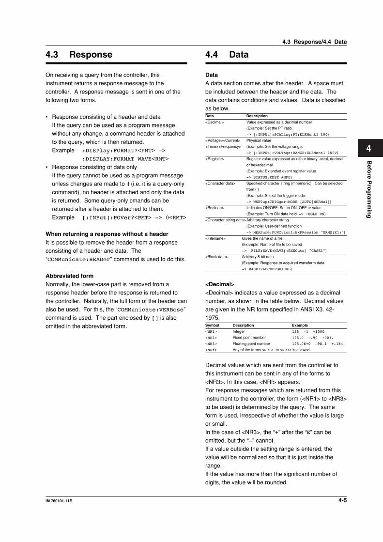
4.4 Data
DataA data section comes after the header. A space must
be included between the header and the data. Thedata contains conditions and values. Data is classifiedas below.Data Description
<Decimal> Value expressed as a decimal number
(Example: Set the PT ratio.
-> [:INPUt]:SCALing:PT:ELEMent1 100)
<Voltage><Current> Physical value
<Time><Frequency> (Example: Set the voltage range.
-> [:INPUt]:VOLTage:RANGE:ELEMent1 100V)
<Register> Register value expressed as either binary, octal, decimal
or hexadecimal
(Example: Extended event register value
-> STATUS:EESE #HFE)
<Character data> Specified character string (mnemonic). Can be selected
from { }
(Example: Select the trigger mode.
-> WSETup:TRIGger:MODE {AUTO|NORMal})
<Boolean> Indicates ON/OFF. Set to ON, OFF or value
(Example: Turn ON data hold. -> :HOLD ON)
<Character string data>Arbitrary character string
(Example: User-defined function
-> MEASure:FUNCtion1:EXPRession "URMS(E1)")
<Filename> Gives the name of a file.
(Example: Name of file to be saved
-> FILE:SAVE:WAVE[:EXECute] "CASE1")
<Block data> Arbitrary 8-bit data
(Example: Response to acquired waveform data
-> #40012ABCDEFGHIJKL)
<Decimal><Decimal> indicates a value expressed as a decimal
number, as shown in the table below. Decimal valuesare given in the NR form specified in ANSI X3. 42-1975.Symbol Description Example
<NR1> Integer 125 -1 +1000
<NR2> Fixed point number 125.0 –.90 +001.
<NR3> Floating point number 125.0E+0 –9E–1 +.1E4
<NRf> Any of the forms <NR1> to <NR3> is allowed.
Decimal values which are sent from the controller tothis instrument can be sent in any of the forms to
<NR3>. In this case, <NRf> appears.For response messages which are returned from thisinstrument to the controller, the form (<NR1> to <NR3>
to be used) is determined by the query. The sameform is used, irrespective of whether the value is largeor small.
In the case of <NR3>, the “+” after the “E” can beomitted, but the “–” cannot.If a value outside the setting range is entered, the
value will be normalized so that it is just inside therange.If the value has more than the significant number of
digits, the value will be rounded.
4.3 Response/4.4 Data
4-6 IM 760101-11E
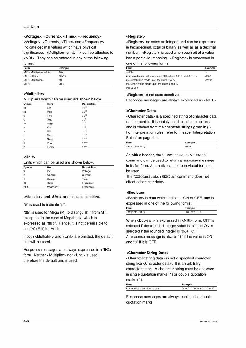
<Voltage>, <Current>, <Time>, <Frequency><Voltage>, <Current>, <Time> and <Frequency>indicate decimal values which have physicalsignificance. <Multiplier> or <Unit> can be attached to
<NRf>. They can be entered in any of the followingforms.Form Example
<NRf><Multiplier><Unit> 5MV
<NRf><Unit> 5E-3V
<NRf><Multiplier> 5M
<NRf> 5E-3
<Multiplier>Multipliers which can be used are shown below.Symbol Word Description
EX Exa 1018
PE Peta 1015
T Tera 1012
G Giga 109
MA Mega 106
K Kilo 103
M Mili 10-3
U Micro 10-6
N Nano 10-9
P Pico 10-12
F Femto 10-15
<Unit>Units which can be used are shown below.Symbol Word Description
V Volt Voltage
A Ampere Current
S Second Time
HZ Hertz Frequency
MHZ Megahertz Frequency
<Multiplier> and <Unit> are not case sensitive.
“U” is used to indicate “µ”.
“MA” is used for Mega (M) to distinguish it from Mili,
except for in the case of Megahertz, which isexpressed as “MHZ”. Hence, it is not permissible touse “M” (Mili) for Hertz.
If both <Multiplier> and <Unit> are omitted, the defaultunit will be used.
Response messages are always expressed in <NR3>
form. Neither <Multiplier> nor <Unit> is used,therefore the default unit is used.
<Register><Register> indicates an integer, and can be expressedin hexadecimal, octal or binary as well as as a decimalnumber. <Register> is used when each bit of a value
has a particular meaning. <Register> is expressed inone of the following forms.Form Example
<NRf> 1
#H<Hexadecimal value made up of the digits 0 to 9, and A to F> #H0F
#Q<Octal value made up of the digits 0 to 7> #Q777
#B<Binary value made up of the digits 0 and 1>
#B001100
<Register> is not case sensitive.
Response messages are always expressed as <NR1>.
<Character Data><Character data> is a specified string of character data(a mnemonic). It is mainly used to indicate options,and is chosen from the character strings given in { }.
For interpretation rules, refer to “Header InterpretationRules” on page 4-4.Form Example
{AUTO|NORMal} AUTO
As with a header, the “COMMunicate:VERBose”command can be used to return a response message
in its full form. Alternatively, the abbreviated form canbe used.The “COMMunicate:HEADer” command does not
affect <character data>.
<Boolean><Boolean> is data which indicates ON or OFF, and isexpressed in one of the following forms.Form Example
{ON|OFF|<NRf>} ON OFF 1 0
When <Boolean> is expressed in <NRf> form, OFF isselected if the rounded integer value is “0” and ON isselected if the rounded integer is “Not 0”.
A response message is always “1” if the value is ONand “0” if it is OFF.
<Character String Data><Character string data> is not a specified characterstring like <Character data>. It is an arbitrary
character string. A character string must be enclosedin single quotation marks (') or double quotationmarks (").Form Example
<Character string data> "ABC" "IEEE488.2-1987"
Response messages are always enclosed in double
quotation marks.
4.4 Data
Befo
re Pro
gram
min
g
4-7IM 760101-11E
4
If a character string contains a double quotation mark("), the double quotation mark will be replaced by two
concatenated double quotation marks (""). This rulealso applies to a single quotation mark within acharacter string.
<Character string data> is an arbitrary character string,therefore this instrument assumes that the remaining
program message units are part of the character stringif no single (') or double quotation mark (") isencountered. As a result, no error will be detected if a
quotation mark is omitted.
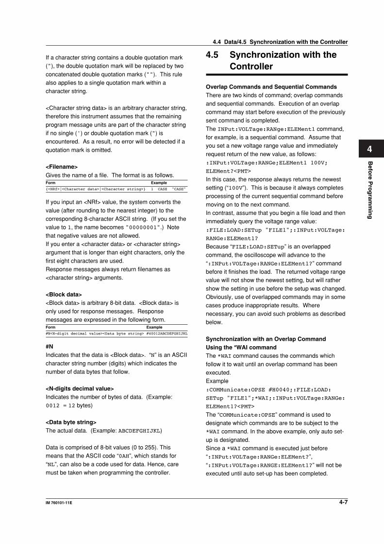
<Filename>Gives the name of a file. The format is as follows.Form Example
{<NRf>|<Character data>|<Character string>} 1 CASE "CASE"
If you input an <NRf> value, the system converts the
value (after rounding to the nearest integer) to thecorresponding 8-character ASCII string. (If you set thevalue to 1, the name becomes "00000001".) Note
that negative values are not allowed.If you enter a <character data> or <character string>argument that is longer than eight characters, only the
first eight characters are used.Response messages always return filenames as<character string> arguments.
<Block data><Block data> is arbitrary 8-bit data. <Block data> is
only used for response messages. Responsemessages are expressed in the following form.Form Example
#N<N-digit decimal value><Data byte string> #40012ABCDEFGHIJKL
#NIndicates that the data is <Block data>. “N” is an ASCII
character string number (digits) which indicates thenumber of data bytes that follow.
<N-digits decimal value>Indicates the number of bytes of data. (Example:0012 = 12 bytes)
<Data byte string>The actual data. (Example: ABCDEFGHIJKL)
Data is comprised of 8-bit values (0 to 255). Thismeans that the ASCII code “0AH”, which stands for
“NL”, can also be a code used for data. Hence, caremust be taken when programming the controller.
4.5 Synchronization with theController
Overlap Commands and Sequential CommandsThere are two kinds of command; overlap commands
and sequential commands. Execution of an overlapcommand may start before execution of the previouslysent command is completed.
The INPut:VOLTage:RANge:ELEMent1 command,for example, is a sequential command. Assume thatyou set a new voltage range value and immediately
request return of the new value, as follows::INPut:VOLTage:RANGe;ELEMent1 100V;
ELEMent?<PMT>
In this case, the response always returns the newestsetting (“100V”). This is because it always completesprocessing of the current sequential command before
moving on to the next command.In contrast, assume that you begin a file load and thenimmediately query the voltage range value:
:FILE:LOAD:SETup "FILE1";:INPut:VOLTage:
RANGe:ELEMent1?
Because “FILE:LOAD:SETup” is an overlapped
command, the oscilloscope will advance to the“:INPut:VOLTage:RANGe:ELEMent1?” commandbefore it finishes the load. The returned voltage rangevalue will not show the newest setting, but will rather
show the setting in use before the setup was changed.Obviously, use of overlapped commands may in somecases produce inappropriate results. Where
necessary, you can avoid such problems as describedbelow.
Synchronization with an Overlap CommandUsing the *WAI commandThe *WAI command causes the commands which
follow it to wait until an overlap command has beenexecuted.Example
:COMMunicate:OPSE #H0040;:FILE:LOAD:
SETup "FILE1";*WAI;:INPut:VOLTage:RANGe:
ELEMent1?<PMT>
The “COMMunicate:OPSE” command is used todesignate which commands are to be subject to the*WAI command. In the above example, only auto set-
up is designated.Since a *WAI command is executed just before“:INPut:VOLTage:RANGe:ELEMent?”,
“:INPut:VOLTage:RANGE:ELEMent1?” will not beexecuted until auto set-up has been completed.
4.4 Data/4.5 Synchronization with the Controller
4-8 IM 760101-11E
Using the COMMunicate:OVERlap commandThe “COMMunicate:OVERlap” command is used to
enable or disable overlap operation.Example:COMMunicate:OVERlap #HFFBF;:FILE:LOAD:
SETup "FILE1";:INPut:VOLTage:RANGe:
ELEMent1?<PMT>
The “COMMunicate:OVERlap #HFFBF” command
disables overlapped operation of the medium accesscommand, while enabling all other overlap-typeoperations. The oscilloscope will therefore handle
“FILE:LOAD:SETup” s a sequential command,ensuring that the “:INPut:VOLTage:RANGe:ELEMent1?” command (in the above example) will not
execute until file loading is completed.
Using the *OPC commandThe *OPC command causes the OPC bit (bit 0) of thestandard event register (page 6-3) to be set to “1”when an overlap operation has been completed.
Example:COMMunicate:OPSE #H0040;*ESE 1;
*ESR?;*SRE 32;:FILE:LOAD:SETup "FILE1";
*OPC<PMT>
(Response to *ESR? is decoded.)(Service request is awaited.)
:INPut:VOLTage:RANGe:ELEMent1?<PMT>
The “COMMunicate:OPSE” command is used todesignate which commands are to be subject to the
*OPC command. In the above example, only mediumaccess commands are designated.*ESE 1 and *SRE 32 stipulate that a service request
is generated only when the OPC bit is set to “1”.*ESR? is used to clear the standard event register.In the above example,
“:INPut:VOLTage:RANGe:ELEMent1?” will not beexecuted until a service request is generated.
Using the *OPC? queryThe *OPC? query generates a response when an
overlap operation has been completed.Example:COMMunicate:OPSE #H0040;:FILE:LOAD:
SETup "FILE1";*OPC?<PMT>
(Response to *OPC? is decoded.):INPut:VOLTage:RANGe:ELEMent?<PMT>
The “COMMunicate:OPSE” command is used todesignate which commands are to be subject to the*OPC? command. In the above example, only medium
access commands are designated.Since *OPC? does not generate a response until anoverlap operation is completed, file loading will have
been completed when a response to *OPC? is read.
NoteMost commands are sequential commands. Commands used inChapter 5 are sequential commands unless otherwise specified.
Synchronization with Non-Overlap CommandsEven for sequential commands, synchronization is
sometimes required to correctly query the measureddata.If you wish to query the newest numerical data on
every time measured data is updated, for example,sending the “:NUMeric[:NORMal]:VALue?”command at an arbitrary timing can cause data that is
the same as the previous data to be received. This isbecause the WT1600 returns the current measureddata regardless of whether the measured data has
been updated since the previous query.In this case, the following method must be used tosynchronize with the end of the updating of the
measured data.
Using STATus:CONDition? queryThe “STATus:CONDition?” query is used to querythe contents of the condition register (page 6-4). Youcan determine whether the measured data is being
updated by reading bit 0 of the condition register. If bit0 of the condition register is “1,” the measured data isbeing updated. If it is “0,” the measured data can be
queried.
4.5 Synchronization with the Controller
Befo
re Pro
gram
min
g
4-9IM 760101-11E
4
Using the extended event registerChanges in the condition register are reflected in the
extended event register (page 6-4).
Example
:STATus:FILTer1 FALL;:STATus:EESE 1;
EESR?;*SRE 8\<PMT>
(Read the response to :STATus:EESR?)
Loop
(Wait for a service request):NUMeric[:NORMal]:VALue?\<PMT>
(Read the response to :NUMeric[:NORMal]:VALue?):STATus:EESR?\<PMT>
(Read the response to :STATus:EESR?)(Return to LOOP)
The “STATus:FILTer1 FALL” command sets thetransition filter such that Bit 0 (FILTer1) of theExtended Event Register sets to 1 when Bit 0 of the
Condition Register changes from 1 to 0.“STATus:EESE 1” is a command used only to reflectthe status of bit 0 of the extended event register in the
status byte.“STATus:EESR?” is used to clear the extended eventregister.
The “*SRE 8” command is used to generate a servicerequest caused solely by the extended event register.“:NUMeric[:NORMal]:VALue?” will not be executed
until a service request is generated.
Using the COMMunicate:WAIT commandThe “COMMunicate:WAIT” command halts
communications until a specific event is generated.
Example
:STATus:FILTer1 FALL;:STATus:
EESR?\<PMT>
(Read the response to :STATus:EESR?)
Loop
COMMunicate:WAIT 1\<PMT>
:NUMeric[:NORMal]:VALue?\<PMT>
(Read the response to :NUMeric[:NORMal]:VALue?):STATus:EESR?\<PMT>
(Read the response to :STATus:EESR?)(Return to LOOP)
For a description of “STATus:FILTer1 FALL” and“STATus:EESR?”, refer to “Using the extended eventregister” on this page.
“COMMunicate:WAIT 1” means that communicationsis halted until bit 0 of the extended event register is setto “1”.
The “:NUMeric[:NORMal]:VALue?” command willnot be executed until bit 0 of the extended eventregister is set to “1”.
4.5 Synchronization with the Controller
Co
mm
and
s
5-1IM 760101-11E
5
5.1 Command List
Command Function Page
AOUTput Group
:AOUTput? Queries all settings related to the D/A output. 5-12
:AOUTput:HARMonics? Queries all settings related to the D/A output for harmonic measurement. 5-12
:AOUTput:HARMonics:CHANnel<x> Sets the D/A output items for harmonic measurement or queries the current
setting. 5-12
:AOUTput:NORMal? Queries all settings related to the D/A output for normal measurement. 5-13
:AOUTput[:NORMal]:CHANnel<x> Sets the D/A output items for normal measurement or queries the current
setting. 5-13
:AOUTput[:NORMal]:IRTime Sets the rated time of D/A output for integration for harmonic measurement
or queries the current setting. 5-13
COMMunicate Group
:COMMunicate? Queries all settings related to communications. 5-14
:COMMunicate:HEADer Sets whether or not to be added a header to the response to a query or
queries the current setting. 5-14
:COMMunicate:LOCKout Sets or clears local lockout. 5-14
:COMMunicate:OPSE Sets the overlap command that is to used by the *OPC, *OPC?, and *WAI
commands or queries the current setting. 5-15
:COMMunicate:OPSR? Queries the operation pending status register. 5-15
:COMMunicate:OVERlap Sets the commands that will operate as overlap commands or queries the
current setting. 5-15
:COMMunicate:REMote Sets remote or local. 5-15
:COMMunicate:STATus? Queries line-specific status. 5-15
:COMMunicate:VERBose Sets the response messages to full form or abbreviated form or queries the
current setting. 5-15
:COMMunicate:WAIT Waits for a specified extended event. 5-15
:COMMunicate:WAIT? Creates the response that is returned when the specified event occurs. 5-16
CURSor Group
:CURSor? Queries all settings related to the cursor measurement. 5-18
:CURSor:BAR? Queries all settings related to the cursor measurement on the bar graph. 5-18
:CURSor:BAR:POSition<x> Sets the cursor position (order) on the bar graph or queries the current
setting. 5-18
:CURSor:BAR[:STATe] Turns ON/OFF the cursor display on the bar graph or queries the current
setting. 5-18
:CURSor:BAR:{Y<x>|DY}? Queries the cursor measurement value on the bar graph. 5-18
:CURSor:TRENd? Queries all settings related to the cursor measurement on the trend. 5-18
:CURSor:TRENd:POSition<x> Sets the cursor position on the trend or queries the current setting. 5-18
:CURSor:TRENd[:STATe] Turns ON/OFF the cursor display on the trend or queries the current setting. 5-19
:CURSor:TRENd:TRACe<x> Sets the cursor target on the trend or queries the current setting. 5-19
:CURSor:TRENd:{X<x>|Y<x>|DY}? Queries the cursor measurement value on the trend. 5-19
:CURSor:WAVE? Queries all settings related to the cursor measurement on the waveform
display. 5-19
:CURSor:WAVE:PATH Sets the cursor path on the waveform display or queries the current setting. 5-19
:CURSor:WAVE:POSition<x> Sets the cursor position on the waveform display or queries the current
setting. 5-19
:CURSor:WAVE[:STATe] Turns ON/OFF the cursor display on the waveform display or queries the
current setting. 5-19
:CURSor:WAVE:TRACe<x> Sets the cursor target on the waveform display or queries the current setting. 5-19
:CURSor:WAVE:{X<x>|DX|PERDt|Y<x>|DY}?
Queries the cursor measurement value on the waveform display. 5-19
Chapter 5 Commands
5-2 IM 760101-11E
Command Function Page
DISPlay Group
:DISPlay? Queries all settings related to the screen display. 5-23
:DISPlay:BAR? Queries all settings related to the bar graph. 5-23
:DISPlay:BAR:FORMat Sets the display format of the bar graph or queries the current setting. 5-23
:DISPlay:BAR:ITEM<x> Sets the bar graph item (function and element) or queries the current setting. 5-23
:DISPlay:BAR:ORDer Sets the start and end orders of the bar graph or queries the current setting. 5-23
:DISPlay:FORMat Sets the display format or queries the current setting. 5-23
:DISPlay:NUMeric? Queries all settings related to the numerical display. 5-23
:DISPlay[:NUMeric]:HARMonics? Queries all settings related to the numerical display for harmonic
measurement. 5-24
:DISPlay[:NUMeric]:HARMonics:IAMount
Sets the numerical display format for harmonic measurement or queries the
current setting. 5-24
:DISPlay[:NUMeric]:HARMonics:ICURsor
Sets the cursor position on the numerical display for harmonic measurement
or queries the current setting. 5-24
:DISPlay[:NUMeric]:HARMonics:ITEM<x>
Sets the numerical display item for harmonic measurement or queries the
current setting. 5-24
:DISPlay[:NUMeric]:HARMonics:LCURsor
Sets the cursor position on the list display for harmonic measurement or
queries the current setting. 5-25
:DISPlay[:NUMeric]:HARMonics:LIST<x>
Sets the list display item for harmonic measurement or queries the current
setting. 5-25
:DISPlay[:NUMeric]:HARMonics:PRESet
Presets the display order pattern of numerical display items for harmonic
measurement. 5-25
:DISPlay[:NUMeric]:NORMal? Queries all settings related to the numerical display for normal measurement. 5-25
:DISPlay[:NUMeric]:NORMal:FCURsor Sets the cursor position on the numerical display (all display) for normal
measurement or queries the current setting. 5-25
:DISPlay[:NUMeric]:NORMal:IAMount Sets the numerical display format for normal measurement or queries the
current setting. 5-26
:DISPlay[:NUMeric]:NORMal:ICURsor Sets the cursor position on the numerical display (split display) for normal
measurement or queries the current setting. 5-26
:DISPlay[:NUMeric]:NORMal:ITEM<x> Sets the numerical display item for normal measurement or queries the
current setting. 5-26
:DISPlay[:NUMeric]:NORMal:PRESet Presets the display order pattern of numerical display items for normal
measurement. 5-26
:DISPlay:TRENd? Queries all settings related to the trend. 5-26
:DISPlay:TRENd:ALL Collectively turns ON/OFF all trends. 5-27
:DISPlay:TRENd:FORMat Sets the display format of the trend or queries the current setting. 5-27
:DISPlay:TRENd:HARMonics? Queries all settings related to all the trends for harmonic measurement. 5-27
:DISPlay:TRENd:HARMonics:ITEM<x>? Queries all settings related to the trend for harmonic measurement. 5-27
:DISPlay:TRENd:HARMonics:ITEM<x>[:FUNCtion]
Sets the trend item for harmonic measurement or queries the current setting. 5-27
:DISPlay:TRENd:HARMonics:ITEM<x>:SCALing?
Queries all settings related to the scaling of the trend for harmonic
measurement. 5-27
:DISPlay:TRENd:HARMonics:ITEM<x>:SCALing:MODE
Sets the scaling mode of the trend for harmonic measurement or queries the
current setting. 5-27
:DISPlay:TRENd:HARMonics:ITEM<x>:SCALing:VALue
Sets the upper and lower limits of manual scaling of the trend for harmonic
measurement or queries the current setting. 5-28
:DISPlay:TRENd:NORMal? Queries all settings related to all the trends for normal measurement. 5-28
5.1 Command List
Co
mm
and
s
5-3IM 760101-11E
5
Command Function Page
:DISPlay:TRENd:NORMal:ITEM<x>? Queries all settings related to the trend for normal measurement. 5-28
:DISPlay:TRENd:NORMal:ITEM<x>[:FUNCtion]
Sets the trend item for normal measurement or queries the current setting. 5-28
:DISPlay:TRENd:NORMal:ITEM<x>:SCALing?
Queries all settings related to the scaling mode of the trend for normal
measurement. 5-28
:DISPlay:TRENd:NORMal:ITEM<x>:SCALing:MODE
Sets the scaling of the trend for normal measurement or queries the current
setting. 5-28
:DISPlay:TRENd:NORMal:ITEM<x>:SCALing:VALue
Sets the upper and lower limits of manual scaling of the trend for normal
measurement or queries the current setting. 5-29
:DISPlay:TRENd:PDIV Sets the horizontal axis (Point/div) of the trend or queries the current setting. 5-29
:DISPlay:TRENd:RESTart Restarts the trend. 5-29
:DISPlay:TRENd[:SAMPling] Turns ON/OFF the trend waveform sampling or queries the current setting. 5-29
:DISPlay:TRENd:TDIV Sets the horizontal axis (T/div) of the trend for normal measurement or queries
the current setting. 5-29
:DISPlay:TRENd:T<x> Turns ON/OFF the trend or queries the current setting. 5-29
:DISPlay:VECTor? Queries all settings related to the vector display. 5-29
:DISPlay:VECTor:NUMeric Turns ON/OFF the numerical data display for the vector display or queries the
current setting. 5-29
:DISPlay:VECTor:{UMAG|IMAG} Sets the zoom factor for the vector display or queries the current setting. 5-29
:DISPlay:WAVE? Queries all settings related to the waveform display. 5-30
:DISPlay:WAVE:ALL Collectively turns ON/OFF all waveform displays. 5-30
:DISPlay:WAVE:FORMat Sets the display format of the waveform or queries the current setting. 5-30
:DISPlay:WAVE:GRATicule Sets the graticule (grid) type or queries the current setting. 5-30
:DISPlay:WAVE:INTerpolate Sets the interpolation method of the waveform or queries the current setting. 5-30
:DISPlay:WAVE:MAPPing? Queries all settings related to the waveform mapping to the split screen. 5-30
:DISPlay:WAVE:MAPPing[:MODE] Sets the waveform mapping method for the split screen or queries the current
setting. 5-30
:DISPlay:WAVE:MAPPing:{U<x>|I<x>|SPEed|TORQue}
Sets the waveform mapping to the split screen or queries the current setting. 5-30
:DISPlay:WAVE:SVALue Turns ON/OFF the scale value display or queries the current setting. 5-30
:DISPlay:WAVE:TLABel Turns ON/OFF the waveform labels or queries the current setting. 5-30
:DISPlay:WAVE:{U<x>|I<x>|SPEed|TORQue}
Turns ON/OFF the waveform display or queries the current setting. 5-31
FILE Group
:FILE? Queries all settings related to the file operation. 5-34
:FILE:CDIRectory Changes the current directory. 5-34
:FILE:DELete:IMAGe:{TIFF|BMP|PSCRipt}
Deletes the screen image data file. 5-34
:FILE:DELete:NUMeric:{ASCii|FLOat}
Deletes the numerical data file. 5-34
:FILE:DELete:SETup Deletes the setup parameter file. 5-34
:FILE:DELete:WAVE:{BINary|ASCii|FLOat}
Deletes the waveform display data file. 5-34
:FILE:DRIVe Sets the target drive. 5-35
:FILE:FORMat Executes the floppy disk format. 5-35
:FILE:FREE? Queries the free space on the target drive. 5-35
:FILE:LOAD:ABORt Aborts file loading. 5-35
:FILE:LOAD:SETup Loads the setup parameter file. 5-35
:FILE:MDIRectory Creates a Directory. 5-35
:FILE:PATH? Queries the absolute path of the current directory. 5-35
:FILE:SAVE? Queries all settings related to the saving of files. 5-35
:FILE:SAVE:ABORt Aborts file saving. 5-35
5.1 Command List
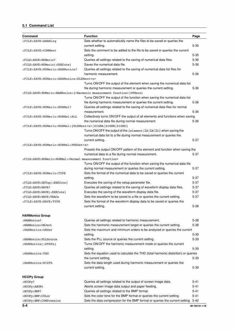
5-4 IM 760101-11E
Command Function Page
:FILE:SAVE:ANAMing Sets whether to automatically name the files to be saved or queries the
current setting. 5-35
:FILE:SAVE:COMMent Sets the comment to be added to the file to be saved or queries the current
setting. 5-35
:FILE:SAVE:NUMeric? Queries all settings related to the saving of numerical data files. 5-36
:FILE:SAVE:NUMeric[:EXECute] Saves the numerical data file. 5-36
:FILE:SAVE:NUMeric:HARMonics? Queries all settings related to the saving of numerical data list files for
harmonic measurement. 5-36
:FILE:SAVE:NUMeric:HARMonics:ELEMent<x>
Turns ON/OFF the output of the element when saving the numerical data list
file during harmonic measurement or queries the current setting. 5-36
:FILE:SAVE:NUMeric:HARMonics:{<Harmonic measurement function>|OTHers}
Turns ON/OFF the output of the function when saving the numerical data list
file during harmonic measurement or queries the current setting. 5-36
:FILE:SAVE:NUMeric:NORMal? Queries all settings related to the saving of numerical data files for normal
measurement. 5-36
:FILE:SAVE:NUMeric:NORMal:ALL Collectively turns ON/OFF the output of all elements and functions when saving
the numerical data file during normal measurement. 5-36
:FILE:SAVE:NUMeric:NORMal:{ELEMent<x>|SIGMA|SIGMB|SIGMC}
Turns ON/OFF the output of the {element|ΣA|ΣB|ΣC} when saving the
numerical data list to a file during normal measurement or queries the
current setting. 5-37
:FILE:SAVE:NUMeric:NORMal:PRESet<x>
Presets the output ON/OFF pattern of the element and function when saving the
numerical data to a file during normal measurement. 5-37
:FILE:SAVE:NUMeric:NORMal:<Normal measurement function>
Turns ON/OFF the output of the function when saving the numerical data file
during normal measurement or queries the current setting. 5-37
:FILE:SAVE:NUMeric:TYPE Sets the format of the numerical data to be saved or queries the current
setting. 5-37
:FILE:SAVE:SETup[:EXECute] Executes the saving of the setup parameter file. 5-37
:FILE:SAVE:WAVE? Queries all settings related to the saving of waveform display data files. 5-37
:FILE:SAVE:WAVE[:EXECute] Executes the saving of the waveform display data file. 5-37
:FILE:SAVE:WAVE:TRACe Sets the waveform to be saved to a file or queries the current setting. 5-37
:FILE:SAVE:WAVE:TYPE Sets the format of the waveform display data to be saved or queries the
current setting. 5-38
HARMonics Group
:HARMonics? Queries all settings related to harmonic measurement. 5-38
:HARMonics:OBJect Sets the harmonic measurement target or queries the current setting. 5-38
:HARMonics:ORDer Sets the maximum and minimum orders to be analyzed or queries the current
setting. 5-39
:HARMonics:PLLSource Sets the PLL source or queries the current setting. 5-39
:HARMonics[:STATe] Turns ON/OFF the harmonic measurement mode or queries the current
setting. 5-39
:HARMonics:THD Sets the equation used to calculate the THD (total harmonic distortion) or queries
the current setting. 5-39
:HARMonics:WIDTh Sets the data length used during harmonic measurement or queries the
current setting. 5-39
HCOPy Group
:HCOPy? Queries all settings related to the output of screen image data. 5-41
:HCOPy:ABORt Aborts screen image data output and paper feeding. 5-41
:HCOPy:BMP? Queries all settings related to the BMP format. 5-41
:HCOPy:BMP:COLor Sets the color tone for the BMP format or queries the current setting. 5-41
:HCOPy:BMP:COMPression Sets the data compression for the BMP format or queries the current setting. 5-42
5.1 Command List
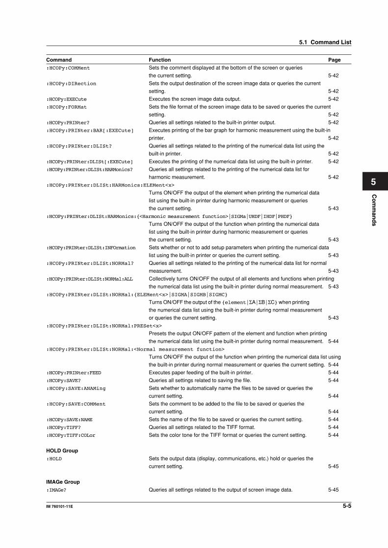
Co
mm
and
s
5-5IM 760101-11E
5
Command Function Page
:HCOPy:COMMent Sets the comment displayed at the bottom of the screen or queries
the current setting. 5-42
:HCOPy:DIRection Sets the output destination of the screen image data or queries the current
setting. 5-42
:HCOPy:EXECute Executes the screen image data output. 5-42
:HCOPy:FORMat Sets the file format of the screen image data to be saved or queries the current
setting. 5-42
:HCOPy:PRINter? Queries all settings related to the built-in printer output. 5-42
:HCOPy:PRINter:BAR[:EXECute] Executes printing of the bar graph for harmonic measurement using the built-in
printer. 5-42
:HCOPy:PRINter:DLISt? Queries all settings related to the printing of the numerical data list using the
built-in printer. 5-42
:HCOPy:PRINter:DLISt[:EXECute] Executes the printing of the numerical data list using the built-in printer. 5-42
:HCOPy:PRINter:DLISt:HARMonics? Queries all settings related to the printing of the numerical data list for
harmonic measurement. 5-42
:HCOPy:PRINter:DLISt:HARMonics:ELEMent<x>
Turns ON/OFF the output of the element when printing the numerical data
list using the built-in printer during harmonic measurement or queries
the current setting. 5-43
:HCOPy:PRINter:DLISt:HARMonics:{<Harmonic measurement function>|SIGMa|UHDF|IHDF|PHDF}
Turns ON/OFF the output of the function when printing the numerical data
list using the built-in printer during harmonic measurement or queries
the current setting. 5-43
:HCOPy:PRINter:DLISt:INFOrmation Sets whether or not to add setup parameters when printing the numerical data
list using the built-in printer or queries the current setting. 5-43
:HCOPy:PRINter:DLISt:NORMal? Queries all settings related to the printing of the numerical data list for normal
measurement. 5-43
:HCOPy:PRINter:DLISt:NORMal:ALL Collectively turns ON/OFF the output of all elements and functions when printing
the numerical data list using the built-in printer during normal measurement. 5-43
:HCOPy:PRINter:DLISt:NORMal:{ELEMent<x>|SIGMA|SIGMB|SIGMC}
Turns ON/OFF the output of the {element|ΣA|ΣB|ΣC} when printing
the numerical data list using the built-in printer during normal measurement
or queries the current setting. 5-43
:HCOPy:PRINter:DLISt:NORMal:PRESet<x>
Presets the output ON/OFF pattern of the element and function when printing
the numerical data list using the built-in printer during normal measurement. 5-44
:HCOPy:PRINter:DLISt:NORMal:<Normal measurement function>
Turns ON/OFF the output of the function when printing the numerical data list using
the built-in printer during normal measurement or queries the current setting. 5-44
:HCOPy:PRINter:FEED Executes paper feeding of the built-in printer. 5-44
:HCOPy:SAVE? Queries all settings related to saving the file. 5-44
:HCOPy:SAVE:ANAMing Sets whether to automatically name the files to be saved or queries the
current setting. 5-44
:HCOPy:SAVE:COMMent Sets the comment to be added to the file to be saved or queries the
current setting. 5-44
:HCOPy:SAVE:NAME Sets the name of the file to be saved or queries the current setting. 5-44
:HCOPy:TIFF? Queries all settings related to the TIFF format. 5-44
:HCOPy:TIFF:COLor Sets the color tone for the TIFF format or queries the current setting. 5-44
HOLD Group
:HOLD Sets the output data (display, communications, etc.) hold or queries the
current setting. 5-45
IMAGe Group
:IMAGe? Queries all settings related to the output of screen image data. 5-45
5.1 Command List
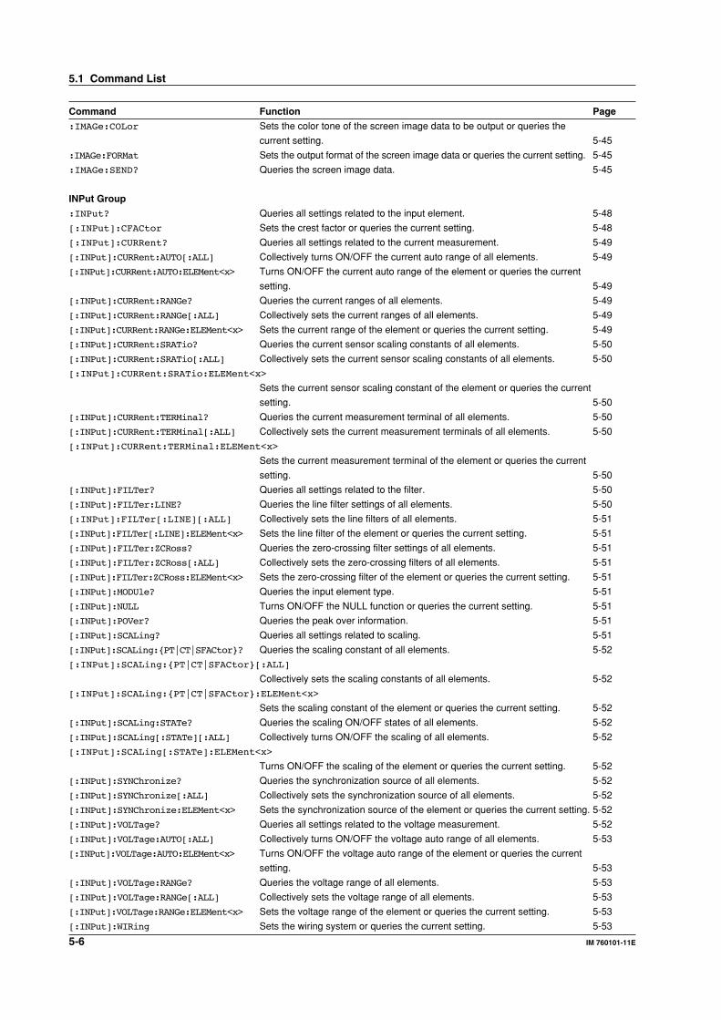
5-6 IM 760101-11E
Command Function Page
:IMAGe:COLor Sets the color tone of the screen image data to be output or queries the
current setting. 5-45
:IMAGe:FORMat Sets the output format of the screen image data or queries the current setting. 5-45
:IMAGe:SEND? Queries the screen image data. 5-45
INPut Group
:INPut? Queries all settings related to the input element. 5-48
[:INPut]:CFACtor Sets the crest factor or queries the current setting. 5-48
[:INPut]:CURRent? Queries all settings related to the current measurement. 5-49
[:INPut]:CURRent:AUTO[:ALL] Collectively turns ON/OFF the current auto range of all elements. 5-49
[:INPut]:CURRent:AUTO:ELEMent<x> Turns ON/OFF the current auto range of the element or queries the current
setting. 5-49
[:INPut]:CURRent:RANGe? Queries the current ranges of all elements. 5-49
[:INPut]:CURRent:RANGe[:ALL] Collectively sets the current ranges of all elements. 5-49
[:INPut]:CURRent:RANGe:ELEMent<x> Sets the current range of the element or queries the current setting. 5-49
[:INPut]:CURRent:SRATio? Queries the current sensor scaling constants of all elements. 5-50
[:INPut]:CURRent:SRATio[:ALL] Collectively sets the current sensor scaling constants of all elements. 5-50
[:INPut]:CURRent:SRATio:ELEMent<x>
Sets the current sensor scaling constant of the element or queries the current
setting. 5-50
[:INPut]:CURRent:TERMinal? Queries the current measurement terminal of all elements. 5-50
[:INPut]:CURRent:TERMinal[:ALL] Collectively sets the current measurement terminals of all elements. 5-50
[:INPut]:CURRent:TERMinal:ELEMent<x>
Sets the current measurement terminal of the element or queries the current
setting. 5-50
[:INPut]:FILTer? Queries all settings related to the filter. 5-50
[:INPut]:FILTer:LINE? Queries the line filter settings of all elements. 5-50
[:INPut]:FILTer[:LINE][:ALL] Collectively sets the line filters of all elements. 5-51
[:INPut]:FILTer[:LINE]:ELEMent<x> Sets the line filter of the element or queries the current setting. 5-51
[:INPut]:FILTer:ZCRoss? Queries the zero-crossing filter settings of all elements. 5-51
[:INPut]:FILTer:ZCRoss[:ALL] Collectively sets the zero-crossing filters of all elements. 5-51
[:INPut]:FILTer:ZCRoss:ELEMent<x> Sets the zero-crossing filter of the element or queries the current setting. 5-51
[:INPut]:MODUle? Queries the input element type. 5-51
[:INPut]:NULL Turns ON/OFF the NULL function or queries the current setting. 5-51
[:INPut]:POVer? Queries the peak over information. 5-51
[:INPut]:SCALing? Queries all settings related to scaling. 5-51
[:INPut]:SCALing:{PT|CT|SFACtor}? Queries the scaling constant of all elements. 5-52
[:INPut]:SCALing:{PT|CT|SFACtor}[:ALL]
Collectively sets the scaling constants of all elements. 5-52
[:INPut]:SCALing:{PT|CT|SFACtor}:ELEMent<x>
Sets the scaling constant of the element or queries the current setting. 5-52
[:INPut]:SCALing:STATe? Queries the scaling ON/OFF states of all elements. 5-52
[:INPut]:SCALing[:STATe][:ALL] Collectively turns ON/OFF the scaling of all elements. 5-52
[:INPut]:SCALing[:STATe]:ELEMent<x>
Turns ON/OFF the scaling of the element or queries the current setting. 5-52
[:INPut]:SYNChronize? Queries the synchronization source of all elements. 5-52
[:INPut]:SYNChronize[:ALL] Collectively sets the synchronization source of all elements. 5-52
[:INPut]:SYNChronize:ELEMent<x> Sets the synchronization source of the element or queries the current setting. 5-52
[:INPut]:VOLTage? Queries all settings related to the voltage measurement. 5-52
[:INPut]:VOLTage:AUTO[:ALL] Collectively turns ON/OFF the voltage auto range of all elements. 5-53
[:INPut]:VOLTage:AUTO:ELEMent<x> Turns ON/OFF the voltage auto range of the element or queries the current
setting. 5-53
[:INPut]:VOLTage:RANGe? Queries the voltage range of all elements. 5-53
[:INPut]:VOLTage:RANGe[:ALL] Collectively sets the voltage range of all elements. 5-53
[:INPut]:VOLTage:RANGe:ELEMent<x> Sets the voltage range of the element or queries the current setting. 5-53
[:INPut]:WIRing Sets the wiring system or queries the current setting. 5-53
5.1 Command List
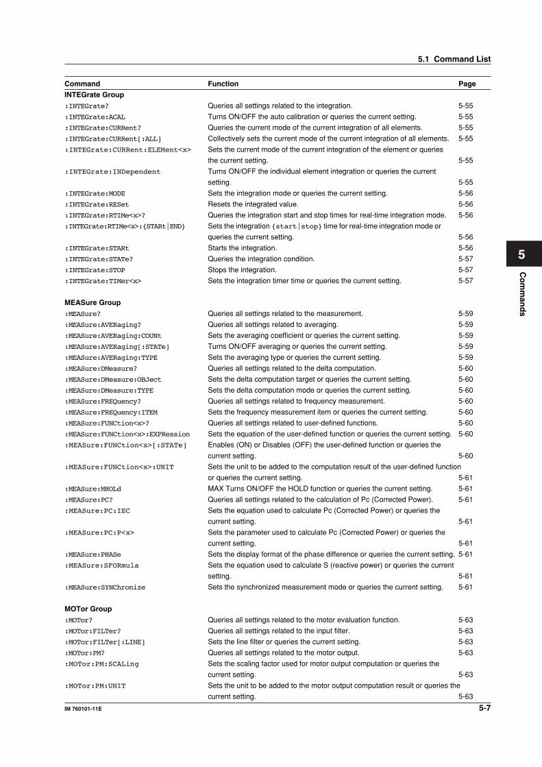
Co
mm
and
s
5-7IM 760101-11E
5
Command Function Page
INTEGrate Group
:INTEGrate? Queries all settings related to the integration. 5-55
:INTEGrate:ACAL Turns ON/OFF the auto calibration or queries the current setting. 5-55
:INTEGrate:CURRent? Queries the current mode of the current integration of all elements. 5-55
:INTEGrate:CURRent[:ALL] Collectively sets the current mode of the current integration of all elements. 5-55
:INTEGrate:CURRent:ELEMent<x> Sets the current mode of the current integration of the element or queries
the current setting. 5-55
:INTEGrate:INDependent Turns ON/OFF the individual element integration or queries the current
setting. 5-55
:INTEGrate:MODE Sets the integration mode or queries the current setting. 5-56
:INTEGrate:RESet Resets the integrated value. 5-56
:INTEGrate:RTIMe<x>? Queries the integration start and stop times for real-time integration mode. 5-56
:INTEGrate:RTIMe<x>:{STARt|END} Sets the integration {start|stop} time for real-time integration mode or
queries the current setting. 5-56
:INTEGrate:STARt Starts the integration. 5-56
:INTEGrate:STATe? Queries the integration condition. 5-57
:INTEGrate:STOP Stops the integration. 5-57
:INTEGrate:TIMer<x> Sets the integration timer time or queries the current setting. 5-57
MEASure Group
:MEASure? Queries all settings related to the measurement. 5-59
:MEASure:AVERaging? Queries all settings related to averaging. 5-59
:MEASure:AVERaging:COUNt Sets the averaging coefficient or queries the current setting. 5-59
:MEASure:AVERaging[:STATe] Turns ON/OFF averaging or queries the current setting. 5-59
:MEASure:AVERaging:TYPE Sets the averaging type or queries the current setting. 5-59
:MEASure:DMeasure? Queries all settings related to the delta computation. 5-60
:MEASure:DMeasure:OBJect Sets the delta computation target or queries the current setting. 5-60
:MEASure:DMeasure:TYPE Sets the delta computation mode or queries the current setting. 5-60
:MEASure:FREQuency? Queries all settings related to frequency measurement. 5-60
:MEASure:FREQuency:ITEM Sets the frequency measurement item or queries the current setting. 5-60
:MEASure:FUNCtion<x>? Queries all settings related to user-defined functions. 5-60
:MEASure:FUNCtion<x>:EXPRession Sets the equation of the user-defined function or queries the current setting. 5-60
:MEASure:FUNCtion<x>[:STATe] Enables (ON) or Disables (OFF) the user-defined function or queries the
current setting. 5-60
:MEASure:FUNCtion<x>:UNIT Sets the unit to be added to the computation result of the user-defined function
or queries the current setting. 5-61
:MEASure:MHOLd MAX Turns ON/OFF the HOLD function or queries the current setting. 5-61
:MEASure:PC? Queries all settings related to the calculation of Pc (Corrected Power). 5-61
:MEASure:PC:IEC Sets the equation used to calculate Pc (Corrected Power) or queries the
current setting. 5-61
:MEASure:PC:P<x> Sets the parameter used to calculate Pc (Corrected Power) or queries the
current setting. 5-61
:MEASure:PHASe Sets the display format of the phase difference or queries the current setting. 5-61
:MEASure:SFORmula Sets the equation used to calculate S (reactive power) or queries the current
setting. 5-61
:MEASure:SYNChronize Sets the synchronized measurement mode or queries the current setting. 5-61
MOTor Group
:MOTor? Queries all settings related to the motor evaluation function. 5-63
:MOTor:FILTer? Queries all settings related to the input filter. 5-63
:MOTor:FILTer[:LINE] Sets the line filter or queries the current setting. 5-63
:MOTor:PM? Queries all settings related to the motor output. 5-63
:MOTor:PM:SCALing Sets the scaling factor used for motor output computation or queries the
current setting. 5-63
:MOTor:PM:UNIT Sets the unit to be added to the motor output computation result or queries the
current setting. 5-63
5.1 Command List
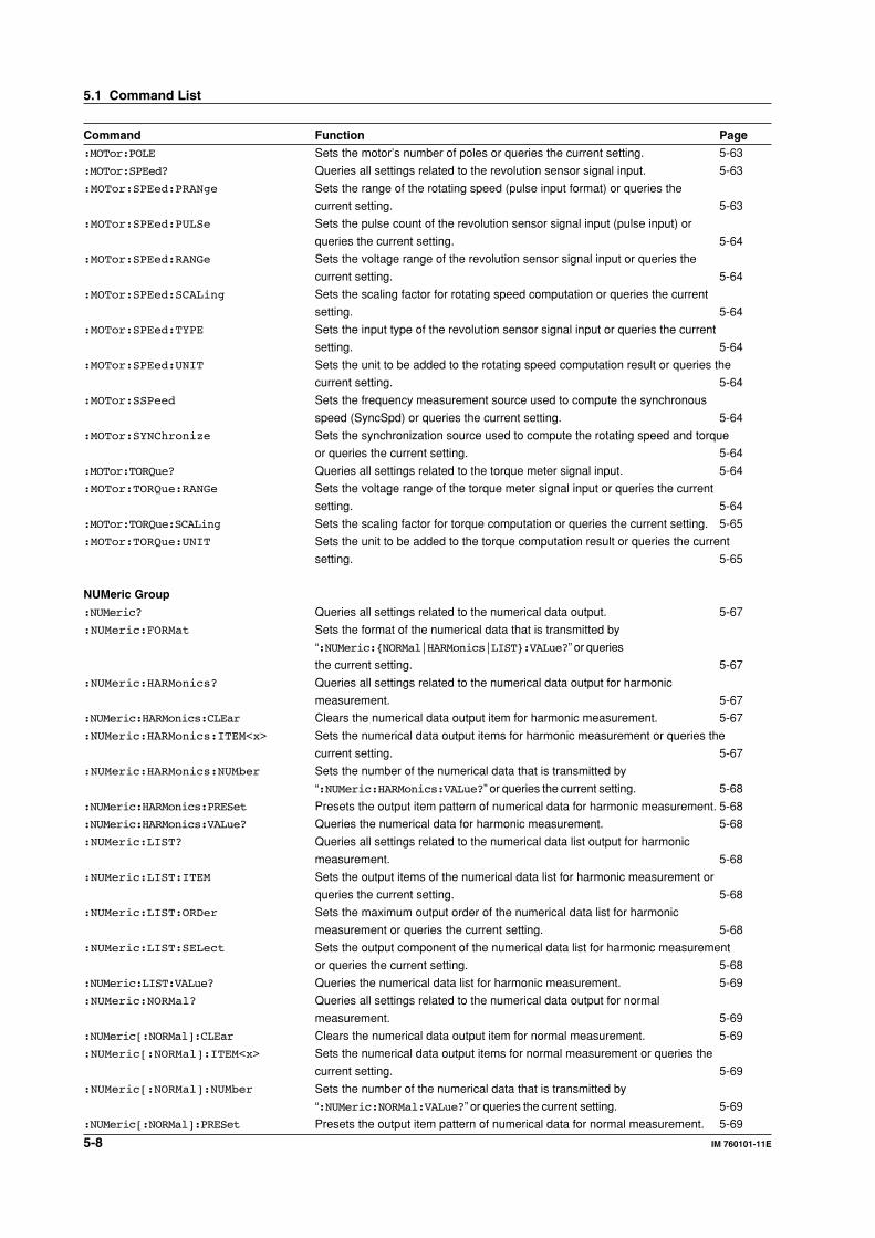
5-8 IM 760101-11E
Command Function Page
:MOTor:POLE Sets the motor’s number of poles or queries the current setting. 5-63
:MOTor:SPEed? Queries all settings related to the revolution sensor signal input. 5-63
:MOTor:SPEed:PRANge Sets the range of the rotating speed (pulse input format) or queries the
current setting. 5-63
:MOTor:SPEed:PULSe Sets the pulse count of the revolution sensor signal input (pulse input) or
queries the current setting. 5-64
:MOTor:SPEed:RANGe Sets the voltage range of the revolution sensor signal input or queries the
current setting. 5-64
:MOTor:SPEed:SCALing Sets the scaling factor for rotating speed computation or queries the current
setting. 5-64
:MOTor:SPEed:TYPE Sets the input type of the revolution sensor signal input or queries the current
setting. 5-64
:MOTor:SPEed:UNIT Sets the unit to be added to the rotating speed computation result or queries the
current setting. 5-64
:MOTor:SSPeed Sets the frequency measurement source used to compute the synchronous
speed (SyncSpd) or queries the current setting. 5-64
:MOTor:SYNChronize Sets the synchronization source used to compute the rotating speed and torque
or queries the current setting. 5-64
:MOTor:TORQue? Queries all settings related to the torque meter signal input. 5-64
:MOTor:TORQue:RANGe Sets the voltage range of the torque meter signal input or queries the current
setting. 5-64
:MOTor:TORQue:SCALing Sets the scaling factor for torque computation or queries the current setting. 5-65
:MOTor:TORQue:UNIT Sets the unit to be added to the torque computation result or queries the current
setting. 5-65
NUMeric Group
:NUMeric? Queries all settings related to the numerical data output. 5-67
:NUMeric:FORMat Sets the format of the numerical data that is transmitted by
“:NUMeric:{NORMal|HARMonics|LIST}:VALue?” or queries
the current setting. 5-67
:NUMeric:HARMonics? Queries all settings related to the numerical data output for harmonic
measurement. 5-67
:NUMeric:HARMonics:CLEar Clears the numerical data output item for harmonic measurement. 5-67
:NUMeric:HARMonics:ITEM<x> Sets the numerical data output items for harmonic measurement or queries the
current setting. 5-67
:NUMeric:HARMonics:NUMber Sets the number of the numerical data that is transmitted by
“:NUMeric:HARMonics:VALue?” or queries the current setting. 5-68
:NUMeric:HARMonics:PRESet Presets the output item pattern of numerical data for harmonic measurement. 5-68
:NUMeric:HARMonics:VALue? Queries the numerical data for harmonic measurement. 5-68
:NUMeric:LIST? Queries all settings related to the numerical data list output for harmonic
measurement. 5-68
:NUMeric:LIST:ITEM Sets the output items of the numerical data list for harmonic measurement or
queries the current setting. 5-68
:NUMeric:LIST:ORDer Sets the maximum output order of the numerical data list for harmonic
measurement or queries the current setting. 5-68
:NUMeric:LIST:SELect Sets the output component of the numerical data list for harmonic measurement
or queries the current setting. 5-68
:NUMeric:LIST:VALue? Queries the numerical data list for harmonic measurement. 5-69
:NUMeric:NORMal? Queries all settings related to the numerical data output for normal
measurement. 5-69
:NUMeric[:NORMal]:CLEar Clears the numerical data output item for normal measurement. 5-69
:NUMeric[:NORMal]:ITEM<x> Sets the numerical data output items for normal measurement or queries the
current setting. 5-69
:NUMeric[:NORMal]:NUMber Sets the number of the numerical data that is transmitted by
“:NUMeric:NORMal:VALue?” or queries the current setting. 5-69
:NUMeric[:NORMal]:PRESet Presets the output item pattern of numerical data for normal measurement. 5-69
5.1 Command List
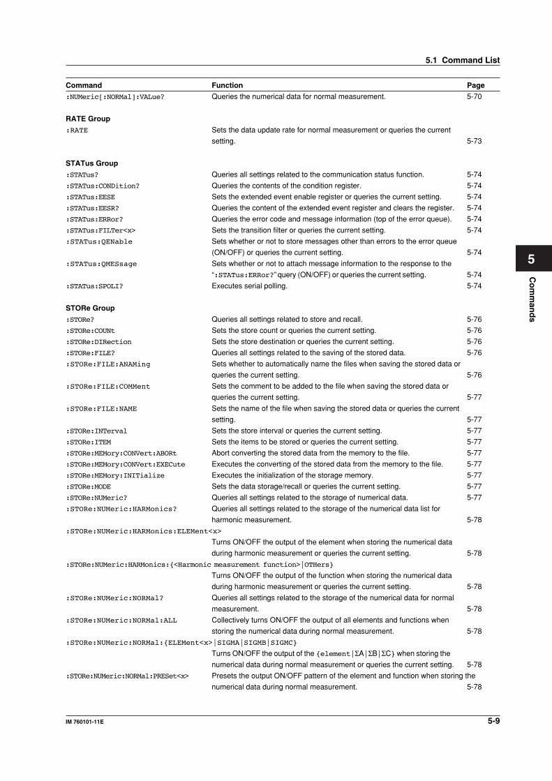
Co
mm
and
s
5-9IM 760101-11E
5
Command Function Page
:NUMeric[:NORMal]:VALue? Queries the numerical data for normal measurement. 5-70
RATE Group
:RATE Sets the data update rate for normal measurement or queries the current
setting. 5-73
STATus Group
:STATus? Queries all settings related to the communication status function. 5-74
:STATus:CONDition? Queries the contents of the condition register. 5-74
:STATus:EESE Sets the extended event enable register or queries the current setting. 5-74
:STATus:EESR? Queries the content of the extended event register and clears the register. 5-74
:STATus:ERRor? Queries the error code and message information (top of the error queue). 5-74
:STATus:FILTer<x> Sets the transition filter or queries the current setting. 5-74
:STATus:QENable Sets whether or not to store messages other than errors to the error queue
(ON/OFF) or queries the current setting. 5-74
:STATus:QMESsage Sets whether or not to attach message information to the response to the
“:STATus:ERRor?” query (ON/OFF) or queries the current setting. 5-74
:STATus:SPOLI? Executes serial polling. 5-74
STORe Group
:STORe? Queries all settings related to store and recall. 5-76
:STORe:COUNt Sets the store count or queries the current setting. 5-76
:STORe:DIRection Sets the store destination or queries the current setting. 5-76
:STORe:FILE? Queries all settings related to the saving of the stored data. 5-76
:STORe:FILE:ANAMing Sets whether to automatically name the files when saving the stored data or
queries the current setting. 5-76
:STORe:FILE:COMMent Sets the comment to be added to the file when saving the stored data or
queries the current setting. 5-77
:STORe:FILE:NAME Sets the name of the file when saving the stored data or queries the current
setting. 5-77
:STORe:INTerval Sets the store interval or queries the current setting. 5-77
:STORe:ITEM Sets the items to be stored or queries the current setting. 5-77
:STORe:MEMory:CONVert:ABORt Abort converting the stored data from the memory to the file. 5-77
:STORe:MEMory:CONVert:EXECute Executes the converting of the stored data from the memory to the file. 5-77
:STORe:MEMory:INITialize Executes the initialization of the storage memory. 5-77
:STORe:MODE Sets the data storage/recall or queries the current setting. 5-77
:STORe:NUMeric? Queries all settings related to the storage of numerical data. 5-77
:STORe:NUMeric:HARMonics? Queries all settings related to the storage of the numerical data list for
harmonic measurement. 5-78
:STORe:NUMeric:HARMonics:ELEMent<x>
Turns ON/OFF the output of the element when storing the numerical data
during harmonic measurement or queries the current setting. 5-78
:STORe:NUMeric:HARMonics:{<Harmonic measurement function>|OTHers}
Turns ON/OFF the output of the function when storing the numerical data
during harmonic measurement or queries the current setting. 5-78
:STORe:NUMeric:NORMal? Queries all settings related to the storage of the numerical data for normal
measurement. 5-78
:STORe:NUMeric:NORMal:ALL Collectively turns ON/OFF the output of all elements and functions when
storing the numerical data during normal measurement. 5-78
:STORe:NUMeric:NORMal:{ELEMent<x>|SIGMA|SIGMB|SIGMC}
Turns ON/OFF the output of the {element|ΣA|ΣB|ΣC} when storing the
numerical data during normal measurement or queries the current setting. 5-78
:STORe:NUMeric:NORMal:PRESet<x> Presets the output ON/OFF pattern of the element and function when storing the
numerical data during normal measurement. 5-78
5.1 Command List
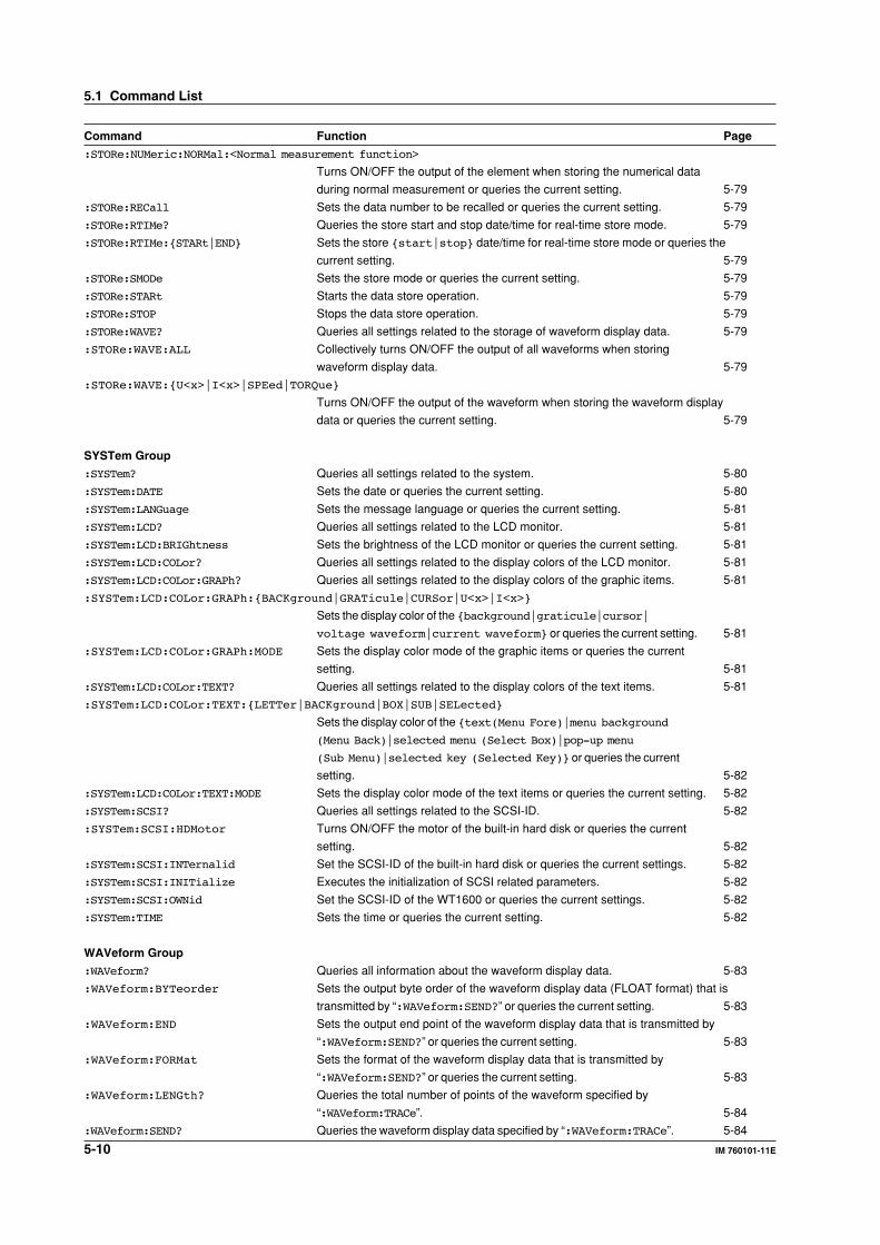
5-10 IM 760101-11E
Command Function Page
:STORe:NUMeric:NORMal:<Normal measurement function>
Turns ON/OFF the output of the element when storing the numerical data
during normal measurement or queries the current setting. 5-79
:STORe:RECall Sets the data number to be recalled or queries the current setting. 5-79
:STORe:RTIMe? Queries the store start and stop date/time for real-time store mode. 5-79
:STORe:RTIMe:{STARt|END} Sets the store {start|stop} date/time for real-time store mode or queries the
current setting. 5-79
:STORe:SMODe Sets the store mode or queries the current setting. 5-79
:STORe:STARt Starts the data store operation. 5-79
:STORe:STOP Stops the data store operation. 5-79
:STORe:WAVE? Queries all settings related to the storage of waveform display data. 5-79
:STORe:WAVE:ALL Collectively turns ON/OFF the output of all waveforms when storing
waveform display data. 5-79
:STORe:WAVE:{U<x>|I<x>|SPEed|TORQue}
Turns ON/OFF the output of the waveform when storing the waveform display
data or queries the current setting. 5-79
SYSTem Group
:SYSTem? Queries all settings related to the system. 5-80
:SYSTem:DATE Sets the date or queries the current setting. 5-80
:SYSTem:LANGuage Sets the message language or queries the current setting. 5-81
:SYSTem:LCD? Queries all settings related to the LCD monitor. 5-81
:SYSTem:LCD:BRIGhtness Sets the brightness of the LCD monitor or queries the current setting. 5-81
:SYSTem:LCD:COLor? Queries all settings related to the display colors of the LCD monitor. 5-81
:SYSTem:LCD:COLor:GRAPh? Queries all settings related to the display colors of the graphic items. 5-81
:SYSTem:LCD:COLor:GRAPh:{BACKground|GRATicule|CURSor|U<x>|I<x>}
Sets the display color of the {background|graticule|cursor|
voltage waveform|current waveform} or queries the current setting. 5-81
:SYSTem:LCD:COLor:GRAPh:MODE Sets the display color mode of the graphic items or queries the current
setting. 5-81
:SYSTem:LCD:COLor:TEXT? Queries all settings related to the display colors of the text items. 5-81
:SYSTem:LCD:COLor:TEXT:{LETTer|BACKground|BOX|SUB|SELected}
Sets the display color of the {text(Menu Fore)|menu background
(Menu Back)|selected menu (Select Box)|pop-up menu
(Sub Menu)|selected key (Selected Key)} or queries the current
setting. 5-82
:SYSTem:LCD:COLor:TEXT:MODE Sets the display color mode of the text items or queries the current setting. 5-82
:SYSTem:SCSI? Queries all settings related to the SCSI-ID. 5-82
:SYSTem:SCSI:HDMotor Turns ON/OFF the motor of the built-in hard disk or queries the current
setting. 5-82
:SYSTem:SCSI:INTernalid Set the SCSI-ID of the built-in hard disk or queries the current settings. 5-82
:SYSTem:SCSI:INITialize Executes the initialization of SCSI related parameters. 5-82
:SYSTem:SCSI:OWNid Set the SCSI-ID of the WT1600 or queries the current settings. 5-82
:SYSTem:TIME Sets the time or queries the current setting. 5-82
WAVeform Group
:WAVeform? Queries all information about the waveform display data. 5-83
:WAVeform:BYTeorder Sets the output byte order of the waveform display data (FLOAT format) that is
transmitted by “:WAVeform:SEND?” or queries the current setting. 5-83
:WAVeform:END Sets the output end point of the waveform display data that is transmitted by
“:WAVeform:SEND?” or queries the current setting. 5-83
:WAVeform:FORMat Sets the format of the waveform display data that is transmitted by
“:WAVeform:SEND?” or queries the current setting. 5-83
:WAVeform:LENGth? Queries the total number of points of the waveform specified by
“:WAVeform:TRACe”. 5-84
:WAVeform:SEND? Queries the waveform display data specified by “:WAVeform:TRACe”. 5-84
5.1 Command List
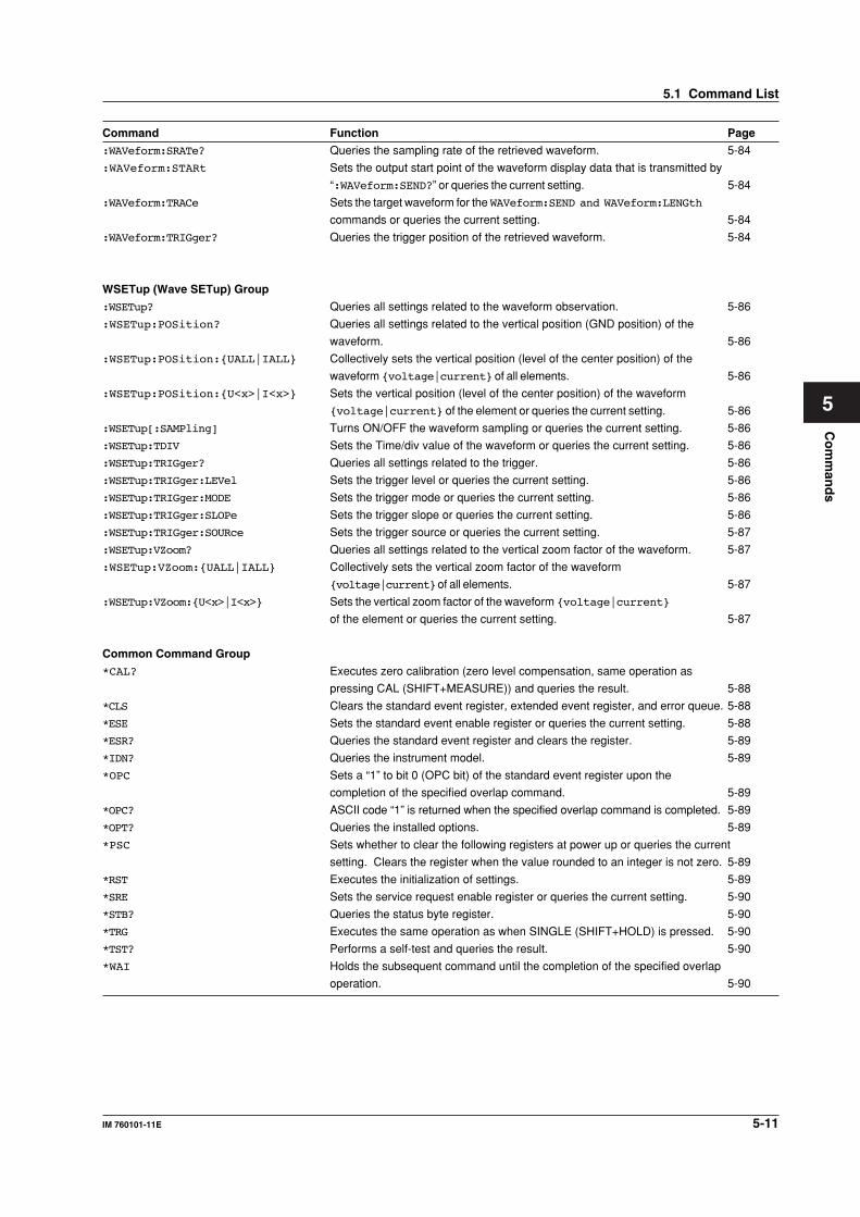
Co
mm
and
s
5-11IM 760101-11E
5
Command Function Page
:WAVeform:SRATe? Queries the sampling rate of the retrieved waveform. 5-84
:WAVeform:STARt Sets the output start point of the waveform display data that is transmitted by
“:WAVeform:SEND?” or queries the current setting. 5-84
:WAVeform:TRACe Sets the target waveform for the WAVeform:SEND and WAVeform:LENGth
commands or queries the current setting. 5-84
:WAVeform:TRIGger? Queries the trigger position of the retrieved waveform. 5-84
WSETup (Wave SETup) Group
:WSETup? Queries all settings related to the waveform observation. 5-86
:WSETup:POSition? Queries all settings related to the vertical position (GND position) of the
waveform. 5-86
:WSETup:POSition:{UALL|IALL} Collectively sets the vertical position (level of the center position) of the
waveform {voltage|current} of all elements. 5-86
:WSETup:POSition:{U<x>|I<x>} Sets the vertical position (level of the center position) of the waveform
{voltage|current} of the element or queries the current setting. 5-86
:WSETup[:SAMPling] Turns ON/OFF the waveform sampling or queries the current setting. 5-86
:WSETup:TDIV Sets the Time/div value of the waveform or queries the current setting. 5-86
:WSETup:TRIGger? Queries all settings related to the trigger. 5-86
:WSETup:TRIGger:LEVel Sets the trigger level or queries the current setting. 5-86
:WSETup:TRIGger:MODE Sets the trigger mode or queries the current setting. 5-86
:WSETup:TRIGger:SLOPe Sets the trigger slope or queries the current setting. 5-86
:WSETup:TRIGger:SOURce Sets the trigger source or queries the current setting. 5-87
:WSETup:VZoom? Queries all settings related to the vertical zoom factor of the waveform. 5-87
:WSETup:VZoom:{UALL|IALL} Collectively sets the vertical zoom factor of the waveform
{voltage|current} of all elements. 5-87
:WSETup:VZoom:{U<x>|I<x>} Sets the vertical zoom factor of the waveform {voltage|current}
of the element or queries the current setting. 5-87
Common Command Group
*CAL? Executes zero calibration (zero level compensation, same operation as
pressing CAL (SHIFT+MEASURE)) and queries the result. 5-88
*CLS Clears the standard event register, extended event register, and error queue. 5-88
*ESE Sets the standard event enable register or queries the current setting. 5-88
*ESR? Queries the standard event register and clears the register. 5-89
*IDN? Queries the instrument model. 5-89
*OPC Sets a “1” to bit 0 (OPC bit) of the standard event register upon the
completion of the specified overlap command. 5-89
*OPC? ASCII code “1” is returned when the specified overlap command is completed. 5-89
*OPT? Queries the installed options. 5-89
*PSC Sets whether to clear the following registers at power up or queries the current
setting. Clears the register when the value rounded to an integer is not zero. 5-89
*RST Executes the initialization of settings. 5-89
*SRE Sets the service request enable register or queries the current setting. 5-90
*STB? Queries the status byte register. 5-90
*TRG Executes the same operation as when SINGLE (SHIFT+HOLD) is pressed. 5-90
*TST? Performs a self-test and queries the result. 5-90
*WAI Holds the subsequent command until the completion of the specified overlap
operation. 5-90
5.1 Command List
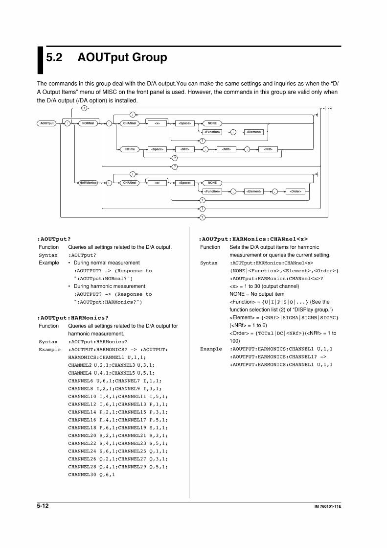
5-12 IM 760101-11E
5.2 AOUTput Group
The commands in this group deal with the D/A output.You can make the same settings and inquiries as when the “D/A Output Items” menu of MISC on the front panel is used. However, the commands in this group are valid only when
the D/A output (/DA option) is installed.
:AOUTput : NORMal : CHANnel <x> <Space> NONE
<Function> , <Element>
?
IRTime <Space> <NRf> , <NRf> , <NRf>
?
?
HARMonics :
;
CHANnel <x> <Space> NONE
<Function> , <Element> , <Order>
?
?
?
;
;
:AOUTput:HARMonics:CHANnel<x>
Function Sets the D/A output items for harmonic
measurement or queries the current setting.
Syntax :AOUTput:HARMonics:CHANnel<x>
{NONE|<Function>,<Element>,<Order>}
:AOUTput:HARMonics:CHANnel<x>?
<x> = 1 to 30 (output channel)
NONE = No output item
<Function> = {U|I|P|S|Q|...} (See the
function selection list (2) of “DISPlay group.”)
<Element> = {<NRf>|SIGMA|SIGMB|SIGMC}
(<NRf> = 1 to 6)
<Order> = {TOTal|DC|<NRf>}(<NRf> = 1 to
100)
Example :AOUTPUT:HARMONICS:CHANNEL1 U,1,1
:AOUTPUT:HARMONICS:CHANNEL1? ->
:AOUTPUT:HARMONICS:CHANNEL1 U,1,1
:AOUTput?
Function Queries all settings related to the D/A output.
Syntax :AOUTput?
Example • During normal measurement
:AOUTPUT? -> (Response to
":AOUTput:NORmal?")
• During harmonic measurement
:AOUTPUT? -> (Response to
":AOUTput:HARMonics?")
:AOUTput:HARMonics?
Function Queries all settings related to the D/A output for
harmonic measurement.
Syntax :AOUTput:HARMonics?
Example :AOUTPUT:HARMONICS? -> :AOUTPUT:
HARMONICS:CHANNEL1 U,1,1;
CHANNEL2 U,2,1;CHANNEL3 U,3,1;
CHANNEL4 U,4,1;CHANNEL5 U,5,1;
CHANNEL6 U,6,1;CHANNEL7 I,1,1;
CHANNEL8 I,2,1;CHANNEL9 I,3,1;
CHANNEL10 I,4,1;CHANNEL11 I,5,1;
CHANNEL12 I,6,1;CHANNEL13 P,1,1;
CHANNEL14 P,2,1;CHANNEL15 P,3,1;
CHANNEL16 P,4,1;CHANNEL17 P,5,1;
CHANNEL18 P,6,1;CHANNEL19 S,1,1;
CHANNEL20 S,2,1;CHANNEL21 S,3,1;
CHANNEL22 S,4,1;CHANNEL23 S,5,1;
CHANNEL24 S,6,1;CHANNEL25 Q,1,1;
CHANNEL26 Q,2,1;CHANNEL27 Q,3,1;
CHANNEL28 Q,4,1;CHANNEL29 Q,5,1;
CHANNEL30 Q,6,1
5-13IM 760101-11E
Co
mm
and
s
5
:AOUTput:NORMal?
Function Queries all settings related to the D/A output for
normal measurement.
Syntax :AOUTput:NORMal?
Example :AOUTPUT:NORMAL? -> :AOUTPUT:
NORMAL:CHANNEL1 U,1;CHANNEL2 U,2;
CHANNEL3 U,3;CHANNEL4 U,4;
CHANNEL5 U,5;CHANNEL6 U,6;
CHANNEL7 I,1;CHANNEL8 I,2;
CHANNEL9 I,3;CHANNEL10 I,4;
CHANNEL11 I,5;CHANNEL12 I,6;
CHANNEL13 P,1;CHANNEL14 P,2;
CHANNEL15 P,3;CHANNEL16 P,4;
CHANNEL17 P,5;CHANNEL18 P,6;
CHANNEL19 S,1;CHANNEL20 S,2;
CHANNEL21 S,3;CHANNEL22 S,4;
CHANNEL23 S,5;CHANNEL24 S,6;
CHANNEL25 Q,1;CHANNEL26 Q,2;
CHANNEL27 Q,3;CHANNEL28 Q,4;
CHANNEL29 Q,5;CHANNEL30 Q,6;
IRTIME 1,0,0
:AOUTput[:NORMal]:CHANnel<x>
Function Sets the D/A output items for normal
measurement or queries the current setting.
Syntax :AOUTput[:NORMal]:CHANnel<x>
{NONE|<Function>,<Element>}
:AOUTput[:NORMal]:CHANnel<x>?
<x> = 1 to 30 (output channel)
NONE = No output item
<Function> = {URMS|UMN|UDC|UAC|IRMS|
...} (See the function selection list (1) of
“DISPlay group.”)
<Element> = {<NRf>|SIGMA|SIGMB|SIGMC}
(<NRf> = 1 to 6)
Example :AOUTPUT:NORMAL:CHANNEL1 URMS,1
:AOUTPUT:NORMAL:CHANNEL1? ->
:AOUTPUT:NORMAL:CHANNEL1 URMS,1
:AOUTput[:NORMal]:IRTime
Function Sets the rated time of D/A output for integration
for harmonic measurement or queries the
current setting.
Syntax :AOUTput[:NORMal]:IRTime {<NRf>,
<NRf>,<NRf>}
:AOUTput[:NORMal]:IRTime?
{<NRf>, <NRf>, <NRf>} = 0, 0, 0 to 10000, 0, 0
1st <NRf> = 0 to 10000 (hour)
2nd <NRf> = 0 to 59 (minute)
3rd <NRf> = 0 to 59 (second)
Example :AOUTPUT:NORMAL:IRTIME 1,0,0
:AOUTPUT:NORMAL:IRTIME? ->
:AOUTPUT:NORMAL:IRTIME 1,0,0
5.2 AOUTput Group
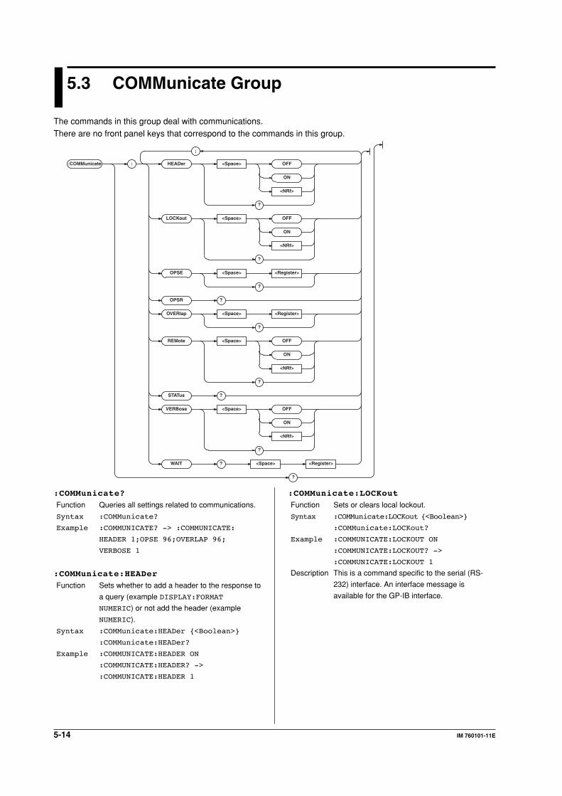
5-14 IM 760101-11E
5.3 COMMunicate Group
The commands in this group deal with communications.There are no front panel keys that correspond to the commands in this group.
:COMMunicate : HEADer <Space> OFF
ON
<NRf>
?
LOCKout <Space> OFF
ON
<NRf>
?
OPSE <Space> <Register>
?
OPSR ?
OVERlap <Space> <Register>
?
REMote <Space> OFF
ON
<NRf>
?
STATus ?
VERBose <Space> OFF
ON
<NRf>
?
WAIT ? <Space> <Register>
?
;
:COMMunicate:LOCKout
Function Sets or clears local lockout.
Syntax :COMMunicate:LOCKout {<Boolean>}
:COMMunicate:LOCKout?
Example :COMMUNICATE:LOCKOUT ON
:COMMUNICATE:LOCKOUT? ->
:COMMUNICATE:LOCKOUT 1
Description This is a command specific to the serial (RS-
232) interface. An interface message is
available for the GP-IB interface.
:COMMunicate?
Function Queries all settings related to communications.
Syntax :COMMunicate?
Example :COMMUNICATE? -> :COMMUNICATE:
HEADER 1;OPSE 96;OVERLAP 96;
VERBOSE 1
:COMMunicate:HEADer
Function Sets whether to add a header to the response to
a query (example DISPLAY:FORMAT
NUMERIC) or not add the header (example
NUMERIC).
Syntax :COMMunicate:HEADer {<Boolean>}
:COMMunicate:HEADer?
Example :COMMUNICATE:HEADER ON
:COMMUNICATE:HEADER? ->
:COMMUNICATE:HEADER 1
5-15IM 760101-11E
Co
mm
and
s
5
:COMMunicate:OPSE (Operation Pending
Status Enable register)
Function Sets the overlap command that is to used by the
*OPC, *OPC?, and *WAI commands or queries
the current setting.
Syntax :COMMunicate:OPSE <Register>
:COMMunicate:OPSE?
<Register> = 0 to 65535, See the figure for the
:COMMunicate:WAIT? command.
Example :COMMUNICATE:OPSE 65535
:COMMUNICATE:OPSE? -> :COMMUNICATE:
OPSE 96
Description In the above example, all bits are set to 1 to
make all overlap commands applicable.
However, bits fixed to 0 are not set to 1. Thus,
the response to the query indicates 1 for bits 5
and 6 only.
:COMMunicate:OPSR?
(Operation Pending Status Register)
Function Queries the value of the operation pending
status register.
Syntax :COMMunicate:OPSR?
Example :COMMUNICATE:OPSR? -> 0
Description For details on the operation pending status
register, see the figure for the
:COMMunicate:WAIT? command.
:COMMunicate:OVERlap
Function Sets the commands that will operate as overlap
commands or queries the current setting.
Syntax :COMMunicate:OVERlap <Register>
:COMMunicate:OVERlap?
<Register> = 0 to 65535, See the figure for the
:COMMunicate:WAIT? command.
Example :COMMUNICATE:OVERLAP 65535
:COMMUNICATE:OVERLAP? ->
:COMMUNICATE:OVERLAP 96
Description • In the above example, all bits are set to 1 to
make all overlap commands applicable.
However, bits fixed to 0 are not set to 1.
Thus, the response to the query indicates 1
for bits 5 and 6 only.
• For the description regarding how to
synchronize the program using
COMMunicate:OVERlap, see page 4-7.
• In the above example, bits 5 and 6 are set to
1 to make all overlap commands applicable
(see the figure for the
:COMMunicate:WAIT? command).
:COMMunicate:REMote
Function Sets remote or local. ON is remote mode.
Syntax :COMMunicate:REMote {<Boolean>}
:COMMunicate:REMote?
Example :COMMUNICATE:REMOTE ON
:COMMUNICATE:REMOTE? ->
:COMMUNICATE:REMOTE 1
Description This is a command specific to the serial (RS-
232) interface. An interface message is
available for the GP-IB interface.
:COMMunicate:STATus?
Function Queries line-specific status.
Syntax :COMMunicate:STATus?
Example :COMMUNICATE:STATUS? ->
:COMMUNICATE:STATUS 0
Description The meaning of each status bit is as follows:
Bit GP-IB RS-232
0 Unrecoverable Parity error
transmission error
1 Always 0 Framing error
2 Always 0 Break character
detected
3 to Always 0 Always 0
The status bit is set when the corresponding
cause occurs and cleared when it is read.
:COMMunicate:VERBose
Function Sets whether to return the response to a query
using full spelling (example DISPLAY:FORMAT
NUMERIC) or using abbreviation (example
DISP:FORM NUM).
Syntax :COMMunicate:VERBose {<Boolean>}
:COMMunicate:VERBose?
Example :COMMUNICATE:VERBOSE ON
:COMMUNICATE:VERBOSE? ->
:COMMUNICATE:VERBOSE 1
:COMMunicate:WAIT
Function Waits for one of the specified extended events
to occur.
Syntax :COMMunicate:WAIT <Register>
<Register> = 0 to 65535 (extended event
register, see page 6-4.)
Example :COMMUNICATE:WAIT 1
Description For the description regarding how to
synchronize the program using
COMMunicate:WAIT, see page 4-8.
5.3 COMMunicate Group
5-16 IM 760101-11E
:COMMunicate:WAIT?
Function Creates the response that is returned when the
specified event occurs.
Syntax :COMMunicate:WAIT? <Register>
<Register>= 0 to 65535 (extended event
register, see page 6-4.)
Example :COMMUNICATE:WAIT? 65535 -> 1
Operation pending status register/overlap
enable register15 14 13 12 11 10 9 8 7 6 5 4 3 2 1 00 0 0 0 0 0 0 0 0 ACS 0 0 0 0 0PRN
When bit 5 (PRN) = 1:
Built-in printer operation and network printer
operation not complete
When bit 6 (ACS) = 1:
Access to the medium not complete.
5.3 COMMunicate Group
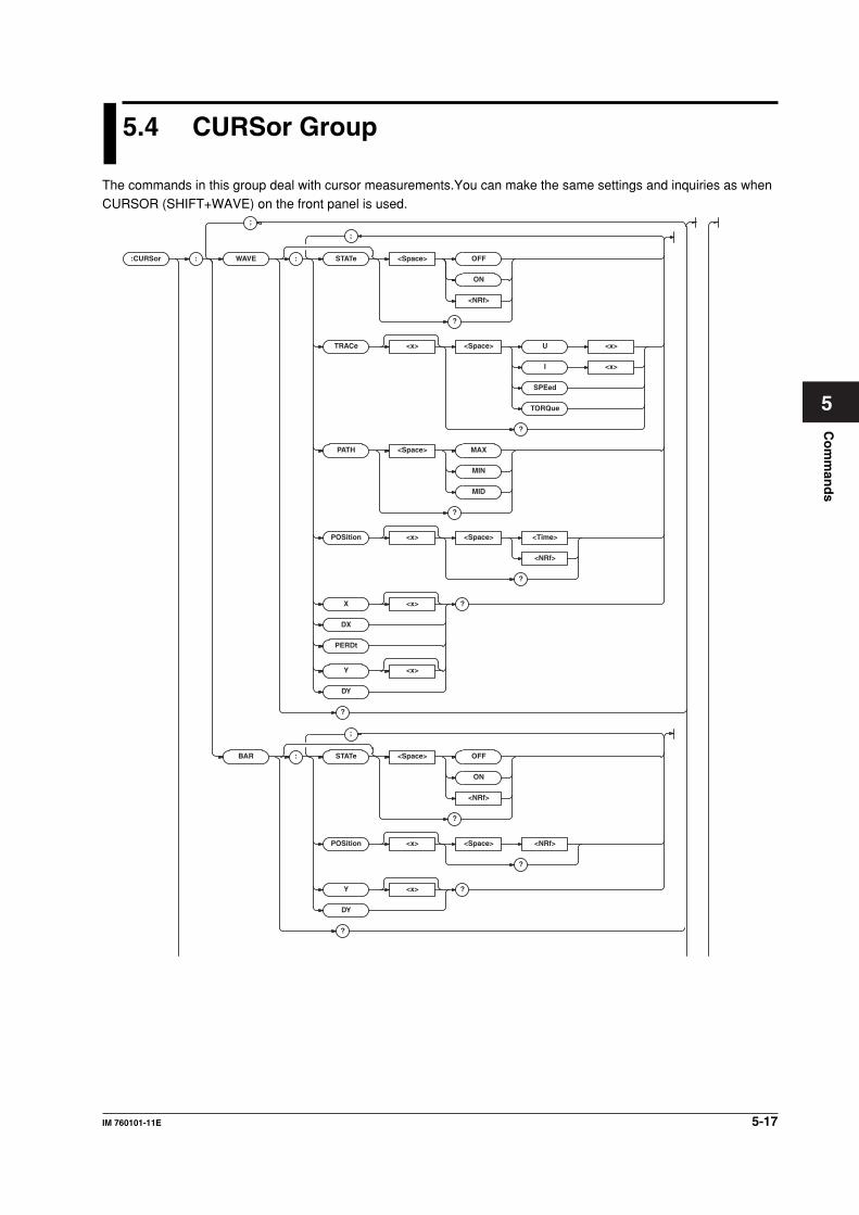
5-17IM 760101-11E
Co
mm
and
s
5
5.4 CURSor Group
The commands in this group deal with cursor measurements.You can make the same settings and inquiries as whenCURSOR (SHIFT+WAVE) on the front panel is used.
:CURSor : WAVE : STAT e <Space> OFF
ON
<NRf>
?
TRACe <x> <Space> U <x>
I <x>
SPEed
TORQue
?
PA TH <Space> MAX
MIN
MID
?
POSition <x> <Space> <Time>
<NRf>
?
X <x> ?
DX
PERDt
Y <x>
DY
?
BAR : STAT e <Space> OFF
ON
<NRf>
?
POSition <x> <Space> <NRf>
?
Y <x> ?
DY
?
;
;
;
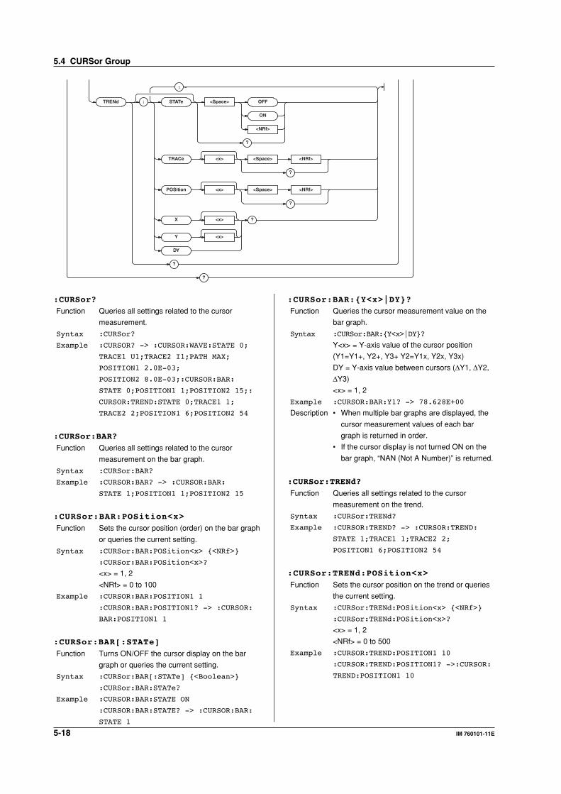
5-18 IM 760101-11E
TRENd : STAT e <Space> OFF
ON
<NRf>
?
TRACe <x> <Space> <NRf>
?
POSition <x> <Space> <NRf>
?
X <x> ?
Y <x>
DY
?
?
;
:CURSor?
Function Queries all settings related to the cursor
measurement.
Syntax :CURSor?
Example :CURSOR? -> :CURSOR:WAVE:STATE 0;
TRACE1 U1;TRACE2 I1;PATH MAX;
POSITION1 2.0E-03;
POSITION2 8.0E-03;:CURSOR:BAR:
STATE 0;POSITION1 1;POSITION2 15;:
CURSOR:TREND:STATE 0;TRACE1 1;
TRACE2 2;POSITION1 6;POSITION2 54
:CURSor:BAR?
Function Queries all settings related to the cursor
measurement on the bar graph.
Syntax :CURSor:BAR?
Example :CURSOR:BAR? -> :CURSOR:BAR:
STATE 1;POSITION1 1;POSITION2 15
:CURSor:BAR:POSition<x>
Function Sets the cursor position (order) on the bar graph
or queries the current setting.
Syntax :CURSor:BAR:POSition<x> {<NRf>}
:CURSor:BAR:POSition<x>?
<x> = 1, 2
<NRf> = 0 to 100
Example :CURSOR:BAR:POSITION1 1
:CURSOR:BAR:POSITION1? -> :CURSOR:
BAR:POSITION1 1
:CURSor:BAR[:STATe]
Function Turns ON/OFF the cursor display on the bar
graph or queries the current setting.
Syntax :CURSor:BAR[:STATe] {<Boolean>}
:CURSor:BAR:STATe?
Example :CURSOR:BAR:STATE ON
:CURSOR:BAR:STATE? -> :CURSOR:BAR:
STATE 1
:CURSor:BAR:{Y<x>|DY}?
Function Queries the cursor measurement value on the
bar graph.
Syntax :CURSor:BAR:{Y<x>|DY}?
Y<x> = Y-axis value of the cursor position
(Y1=Y1+, Y2+, Y3+ Y2=Y1x, Y2x, Y3x)
DY = Y-axis value between cursors (∆Y1, ∆Y2,
∆Y3)
<x> = 1, 2
Example :CURSOR:BAR:Y1? -> 78.628E+00
Description • When multiple bar graphs are displayed, the
cursor measurement values of each bar
graph is returned in order.
• If the cursor display is not turned ON on the
bar graph, “NAN (Not A Number)” is returned.
:CURSor:TRENd?
Function Queries all settings related to the cursor
measurement on the trend.
Syntax :CURSor:TRENd?
Example :CURSOR:TREND? -> :CURSOR:TREND:
STATE 1;TRACE1 1;TRACE2 2;
POSITION1 6;POSITION2 54
:CURSor:TRENd:POSition<x>
Function Sets the cursor position on the trend or queries
the current setting.
Syntax :CURSor:TRENd:POSition<x> {<NRf>}
:CURSor:TRENd:POSition<x>?
<x> = 1, 2
<NRf> = 0 to 500
Example :CURSOR:TREND:POSITION1 10
:CURSOR:TREND:POSITION1? ->:CURSOR:
TREND:POSITION1 10
5.4 CURSor Group
5-19IM 760101-11E
Co
mm
and
s
5
:CURSor:TRENd[:STATe]
Function Turns ON/OFF the cursor display on the trend
or queries the current setting.
Syntax :CURSor:TRENd[:STATe] {<Boolean>}
:CURSor:TRENd:STATe?
Example :CURSOR:TREND:STATE ON
:CURSOR:TREND:STATE? -> :CURSOR:
TREND:STATE 1
:CURSor:TRENd:TRACe<x>
Function Sets the cursor target on the trend or queries
the current setting.
Syntax :CURSor:TRENd:TRACe<x> {<NRf>}
:CURSor:TRENd:TRACe<x>?
<x> = 1, 2
<NRf> = 1 to 16
Example :CURSOR:TREND:TRACE1 1
:CURSOR:TREND:TRACE1? -> :CURSOR:
TREND:TRACE1 1
:CURSor:TRENd:{X<x>|Y<x>|DY}?
Function Queries the cursor measurement value on the
trend.
Syntax :CURSor:TRENd:{X<x>|Y<x>|DY}?
X<x> = Trend time string of the cursor position
(X1=D+, X2=Dx)
Y<x> = Y-axis value of the cursor position
(Y1=Y+, Y2=Yx)
DY = Y-axis value between cursors (∆Y)
<x> = 1, 2
Example :CURSOR:TREND:X1? ->
"2001/04/01 12:34:56"
:CURSOR:TREND:Y1? -> 78.628E+00
Description If the cursor display is not turned ON on the
trend, the following results.
For X<x>: “****/**/** **:**:**” is returned.
For Y<x> and DY: “NAN (Not A Number)” is
returned.
:CURSor:WAVE?
Function Queries all settings related to the cursor
measurement on the waveform display.
Syntax :CURSor:WAVE?
Example :CURSOR:WAVE? -> :CURSOR:WAVE:
STATE 1;TRACE1 U1;TRACE2 I1;
PATH MAX;POSITION1 2.0E-03;
POSITION2 8.0E-03
:CURSor:WAVE:PATH
Function Sets the cursor path on the waveform display or
queries the current setting.
Syntax :CURSor:WAVE:PATH {MAX|MIN|MID}
:CURSor:WAVE:PATH?
Example :CURSOR:WAVE:PATH MAX
:CURSOR:WAVE:PATH? -> :CURSOR:WAVE:
PATH MAX
:CURSor:WAVE:POSition<x>
Function Sets the cursor position on the waveform
display or queries the current setting.
Syntax :CURSor:WAVE:POSition<x> {<Time>|
<NRf>}
:CURSor:WAVE:POSition<x>?
<x> = 1, 2
<Time> = 0 to 5.00 s (during normal
measurement)
<NRf> = 0 to 500 (during harmonic measurement)
Example :CURSOR:WAVE:POSITION1 2MS
:CURSOR:WAVE:POSITION1? -> :CURSOR:
WAVE:POSITION1 2.0E-03
Description The selectable range and resolution of <Time>
is determined by the Time/div value of the
waveform (:WSETup:TDIV).
:CURSor:WAVE[:STATe]
Function Turns ON/OFF the cursor display on the
waveform display or queries the current setting.
Syntax :CURSor:WAVE[:STATe] {<Boolean>}
:CURSor:WAVE:STATe?
Example :CURSOR:WAVE:STATE ON
:CURSOR:WAVE:STATE? -> :CURSOR:
WAVE:STATE 1
:CURSor:WAVE:TRACe<x>
Function Sets the cursor target on the waveform display
or queries the current setting.
Syntax :CURSor:WAVE:TRACe<x> {U<x>|I<x>|
SPEed|TORQue}
:CURSor:WAVE:TRACe<x>?
<x> of TRACe<x> = 1, 2
<x> of U<x>, I<x> = 1 to 6
Example :CURSOR:WAVE:TRACE1 U1
:CURSOR:WAVE:TRACE1? -> :CURSOR:
WAVE:TRACE1 U1
Description {SPEed|TORQue} is valid only when the motor
evaluation function (/MTR option) is installed.
:CURSor:WAVE:{X<x>|DX|PERDt|Y<x>|DY}?
Function Queries the cursor measurement value on the
waveform display.
Syntax :CURSor:WAVE:{X<x>|DX|PERDt|Y<x>|
DY}?
X<x> = X-axis value of the cursor position
(X1=X+, X2=Xx)
DX = X-axis value between cursors (∆X)
PERDt = 1/∆T (1/∆X) value between cursors
Y<x> = Y-axis value of the cursor position
(Y1=Y+, Y2=Yx)
DY = Y-axis value between cursors (∆Y)
<x> = 1, 2
Example :CURSOR:WAVE:Y1? -> 78.628E+00
Description If the cursor display is not turned ON in the
waveform display, “NAN (Not A Number)” is
returned.
5.4 CURSor Group
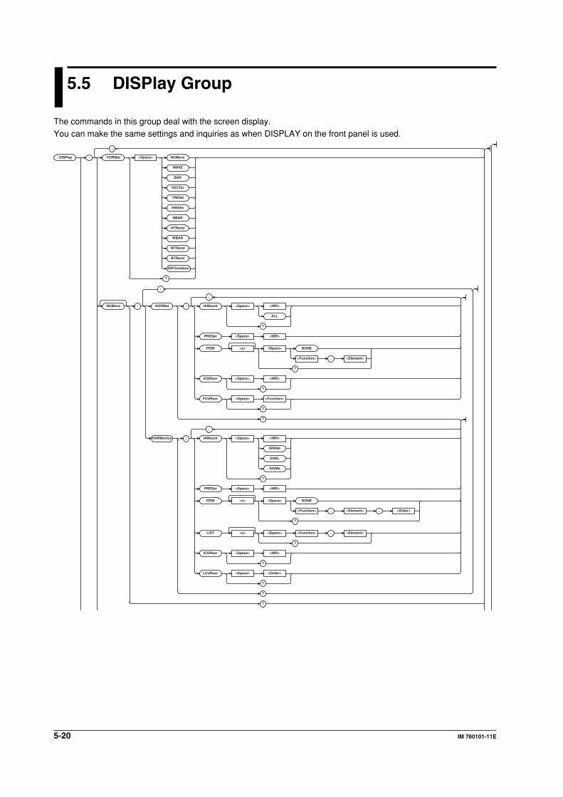
5-20 IM 760101-11E
5.5 DISPlay Group
The commands in this group deal with the screen display.You can make the same settings and inquiries as when DISPLAY on the front panel is used.
:DISPlay : FORMat <Space> NUMeric
WAVE
BAR
VECTor
TRENd
NWAV e
NBAR
NTRend
WBAR
WTRend
BTRend
INFOrmation
?
NUMeric : NORMal : IAMount <Space> <NRf>
ALL
?
PRESet <Space> <NRf>
ITEM <x> <Space> NONE
<Function> , <Element>
?
ICURsor <Space> <NRf>
?
FCURsor <Space> <Function>
?
?
HARMonics : IAMount <Space> <NRf>
SINGle
DUAL
SIGMa
?
PRESet <Space> <NRf>
ITEM <x> <Space> NONE
<Function> , <Element> , <Order>
?
LIST <x> <Space> <Function> , <Element>
?
ICURsor <Space> <NRf>
?
LCURsor <Space> <Order>
?
?
?
;
;
;
;
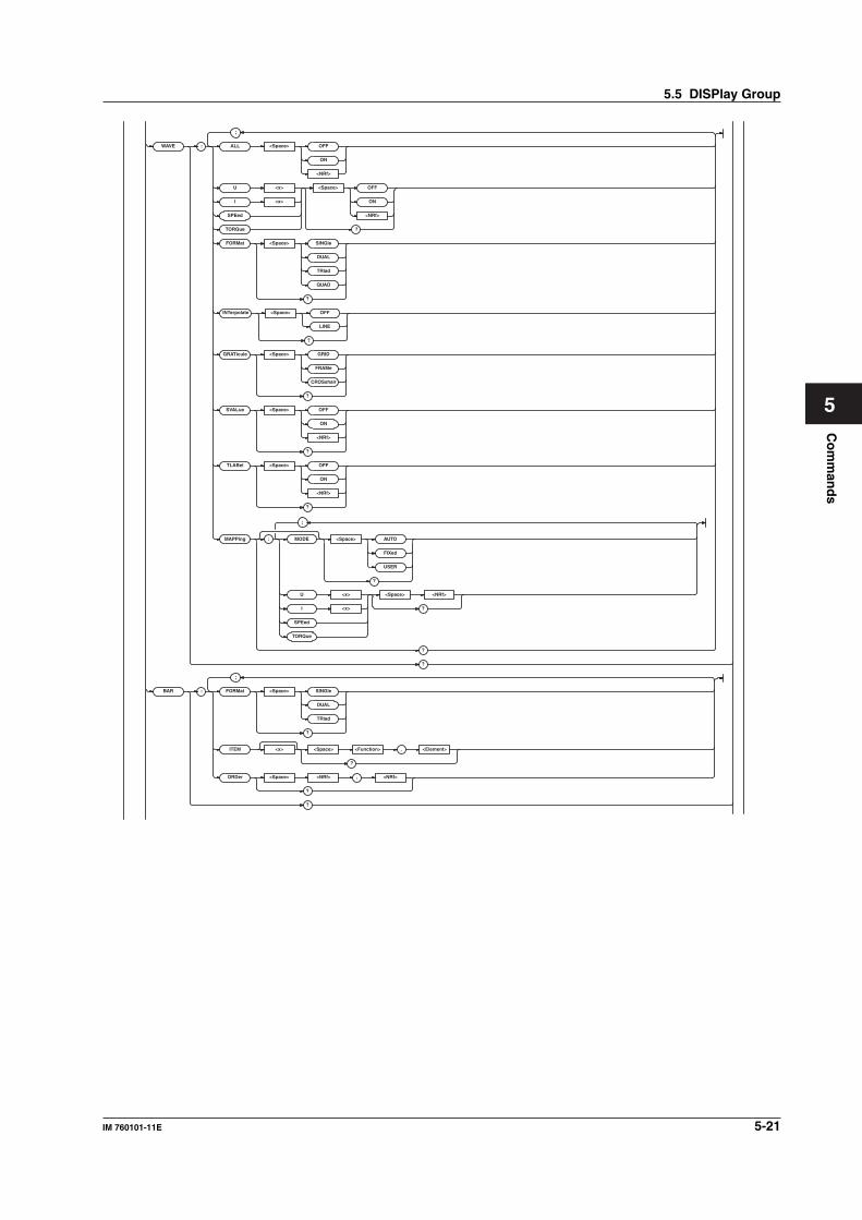
5-21IM 760101-11E
Co
mm
and
s
5
WAVE : ALL <Space> OFF
ON
<NRf>
U <x> <Space> OFF
ON
<NRf>
?
I <x>
SPEed
TORQue
FORMat <Space> SINGle
DUAL
TRIad
QUAD
?
INTerpolate <Space> OFF
LINE
?
GRATicule <Space> GRID
FRAMe
CROSshair
?
SVALue <Space> OFF
ON
<NRf>
?
TLABel <Space> OFF
ON
<NRf>
?
MAPPing : MODE <Space> AUTO
FIXed
USER
?
U <x> <Space> <NRf>
?I <x>
SPEed
TORQue
?
?
BAR : FORMat <Space> SINGle
DUAL
TRIad
?
ITEM <x> <Space> <Function> , <Element>
?
ORDer <Space> <NRf> , <NRf>
?
?
;
;
;
5.5 DISPlay Group
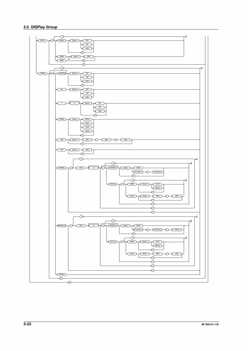
5-22 IM 760101-11E
VECTor : NUMeric <Space> OFF
ON
<NRf>
?
UMAG <Space> <NRf>
?IMAG
?
TRENd : SAMPling <Space> OFF
ON
<NRf>
T <x> <Space> OFF
ON
<NRf>
?
FORMat <Space> SINGle
DUAL
TRIad
QUAD
?
NORMal :
TDIV <Space> <NRf> , <NRf> , <NRf>
?
ITEM <x> : FUNCtion <Space> NONE
<Function> , <Element>
?
SCALing : MODE <Space> AUTO
MANual
?
VALue <Space> <NRf> ,
?
?
?
?
HARMonics :
PDIV <Space> <NRf>
?
ITEM <x> : FUNCtion <Space> NONE
<Function> , <Element> ,
?
SCALing : MODE <Space> AUTO
MANual
?
VALue <Space> <NRf> <NRf>
<Oeder>
<NRf>
,
?
?
?
?
RESTar t
?
;
;
;
;
;
;
;
;
?
ALL <Space> OFF
ON
<NRf>
?
5.5 DISPlay Group
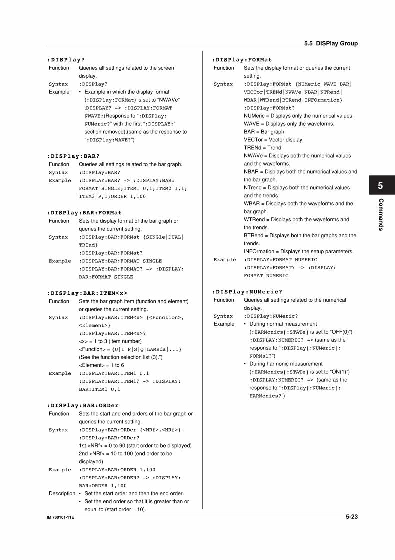
5-23IM 760101-11E
Co
mm
and
s
5
:DISPlay?
Function Queries all settings related to the screen
display.
Syntax :DISPlay?
Example • Example in which the display format
(:DISPlay:FORMat) is set to “NWAVe”
:DISPLAY? -> :DISPLAY:FORMAT
NWAVE;(Response to “:DISPlay:
NUMeric?” with the first “:DISPLAY:”
section removed);(same as the response to
“:DISPlay:WAVE?”)
:DISPlay:BAR?
Function Queries all settings related to the bar graph.
Syntax :DISPlay:BAR?
Example :DISPLAY:BAR? -> :DISPLAY:BAR:
FORMAT SINGLE;ITEM1 U,1;ITEM2 I,1;
ITEM3 P,1;ORDER 1,100
:DISPlay:BAR:FORMat
Function Sets the display format of the bar graph or
queries the current setting.
Syntax :DISPlay:BAR:FORMat {SINGle|DUAL|
TRIad}
:DISPlay:BAR:FORMat?
Example :DISPLAY:BAR:FORMAT SINGLE
:DISPLAY:BAR:FORMAT? -> :DISPLAY:
BAR:FORMAT SINGLE
:DISPlay:BAR:ITEM<x>
Function Sets the bar graph item (function and element)
or queries the current setting.
Syntax :DISPlay:BAR:ITEM<x> {<Function>,
<Element>}
:DISPlay:BAR:ITEM<x>?
<x> = 1 to 3 (item number)
<Function> = {U|I|P|S|Q|LAMBda|...}
(See the function selection list (3).”)
<Element> = 1 to 6
Example :DISPLAY:BAR:ITEM1 U,1
:DISPLAY:BAR:ITEM1? -> :DISPLAY:
BAR:ITEM1 U,1
:DISPlay:BAR:ORDer
Function Sets the start and end orders of the bar graph or
queries the current setting.
Syntax :DISPlay:BAR:ORDer {<NRf>,<NRf>}
:DISPlay:BAR:ORDer?
1st <NRf> = 0 to 90 (start order to be displayed)
2nd <NRf> = 10 to 100 (end order to be
displayed)
Example :DISPLAY:BAR:ORDER 1,100
:DISPLAY:BAR:ORDER? -> :DISPLAY:
BAR:ORDER 1,100
Description • Set the start order and then the end order.
• Set the end order so that it is greater than or
equal to (start order + 10).
:DISPlay:FORMat
Function Sets the display format or queries the current
setting.
Syntax :DISPlay:FORMat {NUMeric|WAVE|BAR|
VECTor|TRENd|NWAVe|NBAR|NTRend|
WBAR|WTRend|BTRend|INFOrmation}
:DISPlay:FORMat?
NUMeric = Displays only the numerical values.
WAVE = Displays only the waveforms.
BAR = Bar graph
VECTor = Vector display
TRENd = Trend
NWAVe = Displays both the numerical values
and the waveforms.
NBAR = Displays both the numerical values and
the bar graph.
NTrend = Displays both the numerical values
and the trends.
WBAR = Displays both the waveforms and the
bar graph.
WTRend = Displays both the waveforms and
the trends.
BTRend = Displays both the bar graphs and the
trends.
INFOrmation = Displays the setup parameters
Example :DISPLAY:FORMAT NUMERIC
:DISPLAY:FORMAT? -> :DISPLAY:
FORMAT NUMERIC
:DISPlay:NUMeric?
Function Queries all settings related to the numerical
display.
Syntax :DISPlay:NUMeric?
Example • During normal measurement
(:HARMonics[:STATe] is set to “OFF(0)”)
:DISPLAY:NUMERIC? -> (same as the
response to “:DISPlay[:NUMeric]:
NORMal?”)
• During harmonic measurement
(:HARMonics[:STATe] is set to “ON(1)”)
:DISPLAY:NUMERIC? -> (same as the
response to “:DISPlay[:NUMeric]:
HARMonics?”)
5.5 DISPlay Group
5-24 IM 760101-11E
:DISPlay[:NUMeric]:HARMonics?
Function Queries all settings related to the numerical
display for harmonic measurement.
Syntax :DISPlay[:NUMeric]:HARMonics?
Example • Example in which the display format of
numeric values (:DISPlay[:NUMeric]:
HARMonics:IAMount) is set to {4|8|16}
value display
:DISPLAY:NUMERIC:HARMONICS? ->
:DISPLAY:NUMERIC:HARMONICS:
IAMOUNT 4;ITEM1 U,1,TOTAL;
ITEM2 I,1,TOTAL;ITEM3 P,1,TOTAL;
...(omitted)...;ITEM100 NONE;
ICURSOR 1
• Example in which the display format of
numeric values (:DISPlay[:NUMeric]:
HARMonics:IAMount) is set to {SINGle|
DUAL} list display
:DISPLAY:NUMERIC:HARMONICS? ->
:DISPLAY:NUMERIC:HARMONICS:
IAMOUNT SINGLE;LIST1 U,1;
LIST2 I,1;LCURSOR 1
:DISPlay[:NUMeric]:HARMonics:IAMount
Function Sets the numerical display format for harmonic
measurement or queries the current setting.
Syntax :DISPlay[:NUMeric]:HARMonics:
IAMount {<NRf>|SINGle|DUAL|SIGMa}
:DISPlay[:NUMeric]:HARMonics:
IAMount?
<NRf> = 4, 8, 16
Example :DISPLAY:NUMERIC:HARMONICS:
IAMOUNT 4
:DISPLAY:NUMERIC:HARMONICS:IAMOUNT?
-> :DISPLAY:NUMERIC:HARMONICS:
IAMOUNT 4
Description The contents of the harmonic measurement
data that are displayed are as follows
depending on the setting of the numerical
display format.
<NRf>: Numerical display items are displayed
in order by the item number.(<NRf> expresses
the number of items that is displayed on a single
screen.)
SINGle: One list display item is listed by
separating the data into even and odd orders.
DUAL: Two list display items are listed in order
by harmonic order.
SIGMa: Rms values of main functions (U, I, P,
S, Q, λ) and the phase difference (φ) between U
and I are displayed for each element.
:DISPlay[:NUMeric]:HARMonics:ICURsor
Function Sets the cursor position on the numerical
display for harmonic measurement or queries
the current setting.
Syntax :DISPlay[:NUMeric]:HARMonics:
ICURsor {<NRf>}
:DISPlay[:NUMeric]:HARMonics:
ICURsor?
<NRf> = 1 to 100
Example :DISPLAY:NUMERIC:HARMONICS:
ICURSOR 1
:DISPLAY:NUMERIC:HARMONICS:ICURSOR?
-> :DISPLAY:NUMERIC:HARMONICS:
ICURSOR 1
Description • Specify the cursor position in terms of the
item number.
• This command is valid when the display
format of numeric values (:DISPlay
[:NUMeric]:HARMonics:IAMount) is set
to {4|8|16} value display.
:DISPlay[:NUMeric]:HARMonics:ITEM<x>
Function Sets the numerical display item for harmonic
measurement or queries the current setting.
Syntax :DISPlay[:NUMeric]:HARMonics:
ITEM<x> {NONE|<Function>,<Element>,
<Order>}
:DISPlay[:NUMeric]:HARMonics:
ITEM<x>?
<x> = 1 to 100 (item number)
NONE = No display item
<Function> = {U|I|P|S|Q|...} (See the
function selection list (2).”)
<Element> = {<NRf>|SIGMA|SIGMB|SIGMC}
(<NRf> = 1 to 6)
<Order> = {TOTal|DC|<NRf>}(<NRf> = 1 to
100)
Example :DISPLAY:NUMERIC:HARMONICS:
ITEM1 U,1,1
:DISPLAY:NUMERIC:HARMONICS:ITEM1?
-> :DISPLAY:NUMERIC:HARMONICS:
ITEM1 U,1,1
Description This command is valid when the display format
of numeric values (:DISPlay[:NUMeric]:
HARMonics:IAMount) is set to {4|8|16}
value display.
5.5 DISPlay Group
5-25IM 760101-11E
Co
mm
and
s
5
:DISPlay[:NUMeric]:HARMonics:LCURsor
Function Sets the cursor position on the list display for
harmonic measurement or queries the current
setting.
Syntax :DISPlay[:NUMeric]:HARMonics:
LCURsor {<Order>}
:DISPlay[:NUMeric]:HARMonics:
LCURsor?
<Order> = {TOTal|DC|<NRf>}(<NRf> = 1 to
100)
Example :DISPLAY:NUMERIC:HARMONICS:
LCURSOR TOTAL
:DISPLAY:NUMERIC:HARMONICS:LCURSOR?
-> :DISPLAY:NUMERIC:HARMONICS:
LCURSOR TOTAL
Description • Specify the cursor position in terms of the
harmonic order.
• This command is valid when the display
format of numeric values (:DISPlay
[:NUMeric]:HARMonics:IAMount) is set
to {SINGle|DUAL|SIGMa} list display.
:DISPlay[:NUMeric]:HARMonics:LIST<x>
Function Sets the list display item for harmonic
measurement or queries the current setting.
Syntax :DISPlay[:NUMeric]:HARMonics:
LIST<x> {<Function>,<Element>}
:DISPlay[:NUMeric]:HARMonics:
LIST<x>?
<x> = 1, 2 (Item number)
<Function> = {U|I|P|S|Q|LAMBda|...}
(See the function selection list (3).”)
<Element> = {<NRf>|SIGMA|SIGMB|SIGMC}
(<NRf> = 1 to 6)
Example :DISPLAY:NUMERIC:HARMONICS:
LIST1 U,1
:DISPLAY:NUMERIC:HARMONICS:LIST1?
-> :DISPLAY:NUMERIC:HARMONICS:
LIST1 U,1
Description This command is valid when the display format
of numeric values (:DISPlay[:NUMeric]:
HARMonics:IAMount) is set to {SINGle|
DUAL} list display.
:DISPlay[:NUMeric]:HARMonics:PRESet
Function Presets the display order pattern of numerical
display items for harmonic measurement.
Syntax :DISPlay[:NUMeric]:HARMonics:
PRESet {<NRf>}
<NRf> = 1 to 4
Example :DISPLAY:NUMERIC:HARMONICS:PRESET 1
Description Regardless of what value (1 to 4) is specified for
<NRf>, the display pattern (order) of the
numerical display items will be the same as the
display order when Reset List Exec of the
Display setting menu, which is displayed on the
WT1600 screen, is executed.For details on the
order of displayed items when reset is executed,
see the WT1600 User’s Manual.
:DISPlay[:NUMeric]:NORMal?
Function Queries all settings related to the numerical
display for normal measurement.
Syntax :DISPlay[:NUMeric]:NORMal?
Example • Example in which the display format of
numeric values (:DISPlay[:NUMeric]
:NORMal:IAMount) is set to “<NRf>(split
display)”
:DISPLAY:NUMERIC:NORMAL? ->
:DISPLAY:NUMERIC:NORMAL:
IAMOUNT 4;ITEM1 URMS,1;
ITEM2 UMN,1;ITEM3
UDC,1;...(omitted)
...;ITEM100 NONE;ICURSOR 1
• Example in which the display format of numeric
values (:DISPlay[:NUMeric]:NORMal:
IAMount) is set to “ALL (all display)”
:DISPLAY:NUMERIC:NORMAL? ->
:DISPLAY:NUMERIC:NORMAL:
IAMOUNT ALL;FCURSOR URMS
:DISPlay[:NUMeric]:NORMal:FCURsor
Function Sets the cursor position on the numerical
display (all display) for normal measurement or
queries the current setting.
Syntax :DISPlay[:NUMeric]:NORMal:
FCURsor {<Function>}
:DISPlay[:NUMeric]:NORMal:FCURsor?
<Function> = {URMS|UMN|UDC|UAC|IRMS|
...} (See the function selection list (1).”)
Example :DISPLAY:NUMERIC:NORMAL:
FCURSOR URMS
:DISPLAY:NUMERIC:NORMAL:FCURSOR? ->
:DISPLAY:NUMERIC:NORMAL:
FCURSOR URMS
Description • Specify the cursor position in terms of the
function.
• This command is valid when the display
format of numeric values (:DISPlay
[:NUMeric]:NORMal:IAMount) is set to
“ALL (all display).”
5.5 DISPlay Group
5-26 IM 760101-11E
:DISPlay[:NUMeric]:NORMal:IAMount
Function Sets the numerical display format for normal
measurement or queries the current setting.
Syntax :DISPlay[:NUMeric]:NORMal:
IAMount {<NRf>|ALL}
:DISPlay[:NUMeric]:NORMal:IAMount?
<NRf> = 4, 8, 16, 42, 78
Example :DISPLAY:NUMERIC:NORMAL:IAMOUNT 4
:DISPLAY:NUMERIC:NORMAL:IAMOUNT? ->
:DISPLAY:NUMERIC:NORMAL:IAMOUNT 4
Description The contents of the measured data that are
displayed are as follows depending on the
setting of the numerical display format.
<NRf>: Numerical display items are displayed
in order by the item number.(<NRf> expresses
the number of items that is displayed on a single
screen.)
ALL: All functions are displayed in order by
element.
:DISPlay[:NUMeric]:NORMal:ICURsor
Function Sets the cursor position on the numerical
display (split display) for normal measurement
or queries the current setting.
Syntax :DISPlay[:NUMeric]:NORMal:
ICURsor {<NRf>}
:DISPlay[:NUMeric]:NORMal:ICURsor?
<NRf> = 1 to 100
Example :DISPLAY:NUMERIC:NORMAL:ICURSOR 1
:DISPLAY:NUMERIC:NORMAL:ICURSOR? ->
:DISPLAY:NUMERIC:NORMAL:ICURSOR 1
Description • Specify the cursor position in terms of the
item number.
• This command is valid when the display
format of numeric values (:DISPlay
[:NUMeric]:NORMal:IAMount) is set to
“<NRf> (split display).”
:DISPlay[:NUMeric]:NORMal:ITEM<x>
Function Sets the numerical display item for normal
measurement or queries the current setting.
Syntax :DISPlay[:NUMeric]:NORMal:ITEM<x>
{NONE|<Function>,<Element>}
:DISPlay[:NUMeric]:NORMal:ITEM<x>?
<x> = 1 to 100 (item number)
NONE = No display item
<Function> = {URMS|UMN|UDC|UAC|IRMS|
...} (See the function selection list (1).”)
<Element> = {<NRf>|SIGMA|SIGMB|SIGMC}
(<NRf> = 1 to 6)
Example :DISPLAY:NUMERIC:NORMAL:
ITEM1 URMS,1
:DISPLAY:NUMERIC:NORMAL:ITEM1? ->
:DISPLAY:NUMERIC:NORMAL:
ITEM1 URMS,1
Description This command is valid when the display format
of numeric values (:DISPlay[:NUMeric]
:NORMal:IAMount) is set to “<NRf> (split
display).”
:DISPlay[:NUMeric]:NORMal:PRESet
Function Presets the display order pattern of numerical
display items for harmonic measurement.
Syntax :DISPlay[:NUMeric]:NORMal:
PRESet {<NRf>}
<NRf> = 1 to 4
Example :DISPLAY:NUMERIC:NORMAL:PRESET 1
Description Regardless of what value (1 to 4) is specified for
<NRf>, the display pattern (order) of the
numerical display items will be the same as the
display order when Reset List Exec of the
Display setting menu, which is displayed on the
WT1600 screen, is executed.For details on the
order of displayed items when reset is executed,
see the WT1600 User’s Manual.
:DISPlay:TRENd?
Function Queries all settings related to the trend.
Syntax :DISPlay:TRENd?
Example :DISPLAY:TREND? -> :DISPLAY:TREND:
SAMPLING 1;T1 1;T2 1;T3 1;T4 1;
T5 1;T6 1;T7 1;T8 1;T9 0;T10 0;
T11 0;T12 0;T13 0;T14 0;T15 0;
T16 0;FORMAT SINGLE;TDIV 0,0,3;
NORMAL:ITEM1:FUNCTION URMS,1;
SCALING:MODE AUTO;VALUE 100.00E+00,
-100.00E+00;:DISPLAY:TREND:NORMAL:
ITEM2:FUNCTION IRMS,1;SCALING:
MODE AUTO;VALUE 100.00E+00,
-100.00E+00;...(omitted)...;:
DISPLAY:TREND:NORMAL:ITEM16:
FUNCTION FU,2;SCALING:MODE AUTO;
VALUE 100.00E+00,-100.00E+00
5.5 DISPlay Group
5-27IM 760101-11E
Co
mm
and
s
5
:DISPlay:TRENd:ALL
Function Collectively turns ON/OFF all trends.
Syntax :DISPlay:TRENd:ALL {<Boolean>}
Example :DISPLAY:TREND:ALL ON
:DISPlay:TRENd:FORMat
Function Sets the display format of the trend or queries
the current setting.
Syntax :DISPlay:TRENd:FORMat {SINGle|DUAL|
TRIad|QUAD}
:DISPlay:TRENd:FORMat?
Example :DISPLAY:TREND:FORMAT SINGLE
:DISPLAY:TREND:FORMAT? ->
:DISPLAY:TREND:FORMAT SINGLE
:DISPlay:TRENd:HARMonics?
Function Queries all settings related to all the trends for
harmonic measurement.
Syntax :DISPlay:TRENd:HARMonics?
Example :DISPLAY:TREND:HARMONICS? ->
:DISPLAY:TREND:HARMONICS:ITEM1:
FUNCTION U,1,1;SCALING:MODE AUTO;
VALUE 100.00E+00,-100.00E+00;:
DISPLAY:TREND:HARMONICS:ITEM2:
FUNCTION I,1,1;SCALING:MODE AUTO;
VALUE 100.00E+00,-100.00E+00;
...(omitted)...;:DISPLAY:TREND:
HARMONICS:ITEM16:FUNCTION PHI,2,1;
SCALING:MODE AUTO;VALUE 100.00E+00,
-100.00E+00
:DISPlay:TRENd:HARMonics:ITEM<x>?
Function Queries all settings related to the trend for
harmonic measurement.
Syntax :DISPlay:TRENd:HARMonics:ITEM<x>?
<x> = 1 to 16 (item number)
Example :DISPLAY:TREND:HARMONICS:ITEM1? ->
:DISPLAY:TREND:HARMONICS:ITEM1:
FUNCTION U,1,1;SCALING:MODE AUTO;
VALUE 100.00E+00,-100.00E+00
:DISPlay:TRENd:HARMonics:ITEM<x>
[:FUNCtion]
Function Sets the trend item for harmonic measurement
or queries the current setting.
Syntax :DISPlay:TRENd:HARMonics:ITEM<x>
[:FUNCtion] {NONE|<Function>,
<Element>,<Order>}
:DISPlay:TRENd:HARMonics:ITEM<x>:
FUNCtion?
<x> = 1 to 16 (item number)
NONE = No display item
<Function> = {U|I|P|S|Q|...} (See the
function selection list (2).”)
<Element> = {<NRf>|SIGMA|SIGMB|SIGMC}
(<NRf> = 1 to 6)
<Order> = {TOTal|DC|<NRf>}(<NRf> = 1 to
100)
Example :DISPLAY:TREND:HARMONICS:ITEM1:
FUNCTION U,1,1
:DISPLAY:TREND:HARMONICS:ITEM1:
FUNCTION? -> :DISPLAY:TREND:
HARMONICS:ITEM1:FUNCTION U,1,1
:DISPlay:TRENd:HARMonics:ITEM<x>:
SCALing?
Function Queries all settings related to the scaling of the
trend for harmonic measurement.
Syntax :DISPlay:TRENd:HARMonics:ITEM<x>:
SCALing?
<x> = 1 to 16 (item number)
Example :DISPLAY:TREND:HARMONICS:ITEM1:
SCALING? -> :DISPLAY:TREND:
HARMONICS:ITEM1:SCALING:MODE AUTO;
VALUE 100.00E+00,-100.00E+00
:DISPlay:TRENd:HARMonics:ITEM<x>:
SCALing:MODE
Function Sets the scaling mode of the trend for harmonic
measurement or queries the current setting.
Syntax :DISPlay:TRENd:HARMonics:ITEM<x>:
SCALing:MODE {AUTO|MANual}
:DISPlay:TRENd:HARMonics:ITEM<x>:
SCALing:MODE?
<x> = 1 to 16 (item number)
Example :DISPLAY:TREND:HARMONICS:ITEM1:
SCALING:MODE AUTO
:DISPLAY:TREND:HARMONICS:ITEM1:
SCALING:MODE? -> :DISPLAY:TREND:
HARMONICS:ITEM1:SCALING:MODE AUTO
5.5 DISPlay Group
5-28 IM 760101-11E
:DISPlay:TRENd:HARMonics:ITEM<x>:
SCALing:VALue
Function Sets the upper and lower limits of manual
scaling of the trend for harmonic measurement
or queries the current setting.
Syntax :DISPlay:TRENd:HARMonics:ITEM<x>:
SCALing:VALue {<NRf>,<NRf>}
:DISPlay:TRENd:HARMonics:ITEM<x>:
SCALing:VALue?
<x> = 1 to 16 (item number)
<NRf> = –9.9999E+30 to 9.9999E+30
Example :DISPLAY:TREND:HARMONICS:ITEM1:
SCALING:VALUE 100,-100
:DISPLAY:TREND:HARMONICS:ITEM1:
SCALING:VALUE? -> :DISPLAY:TREND:
HARMONICS:ITEM1:SCALING:
VALUE 100.00E+00,-100.00E+00
Description • Set the upper limit and then the lower limit.
• This command is valid when the scaling
mode of the trend (:DISPlay:TRENd:
HARMonics:ITEM<x>:SCALing:MODE) is
set to “MANual.”
:DISPlay:TRENd:NORMal?
Function Queries all settings related to all the trends for
normal measurement.
Syntax :DISPlay:TRENd:NORMal?
Example :DISPLAY:TREND:NORMAL? ->
:DISPLAY:TREND:NORMAL:ITEM1:
FUNCTION URMS,1;SCALING:MODE AUTO;
VALUE 100.00E+00,-100.00E+00;:
DISPLAY:TREND:NORMAL:ITEM2:
FUNCTION IRMS,1;SCALING:MODE AUTO;
VALUE 100.00E+00,-100.00E+00;
...(omitted)...;:DISPLAY:TREND:
NORMAL:ITEM16:FUNCTION FU,2;
SCALING:MODE AUTO;VALUE 100.00E+00,
-100.00E+00
:DISPlay:TRENd:NORMal:ITEM<x>?
Function Queries all settings related to the trend for
normal measurement.
Syntax :DISPlay:TRENd:NORMal:ITEM<x>?
<x> = 1 to 16 (item number)
Example :DISPLAY:TREND:NORMAL:ITEM1? ->
:DISPLAY:TREND:NORMAL:ITEM1:
FUNCTION URMS,1;SCALING:MODE AUTO;
VALUE 100.00E+00,-100.00E+00
:DISPlay:TRENd:NORMal:ITEM<x>[:FUNCtion]
Function Sets the trend item for normal measurement or
queries the current setting.
Syntax :DISPlay:TRENd:NORMal:ITEM<x>
[:FUNCtion] {NONE|<Function>,
<Element>}
:DISPlay:TRENd:NORMal:ITEM<x>:
FUNCtion?
<x> = 1 to 16 (item number)
NONE = No display item
<Function> = {URMS|UMN|UDC|UAC|IRMS|
...} (See the function selection list (1).”)
<Element> = {<NRf>|SIGMA|SIGMB|SIGMC}
(<NRf> = 1 to 6)
Example :DISPLAY:TREND:NORMAL:ITEM1:
FUNCTION URMS,1
:DISPLAY:TREND:NORMAL:ITEM1:
FUNCTION? -> :DISPLAY:TREND:NORMAL:
ITEM1:FUNCTION URMS,1
:DISPlay:TRENd:NORMal:ITEM<x>:SCALing?
Function Queries all settings related to the scaling mode
of the trend for normal measurement.
Syntax :DISPlay:TRENd:NORMal:ITEM<x>:
SCALing?
<x> = 1 to 16 (item number)
Example :DISPLAY:TREND:NORMAL:ITEM1:
SCALING? -> :DISPLAY:TREND:NORMAL:
ITEM1:SCALING:MODE AUTO;
VALUE 100.00E+00,-100.00E+00
:DISPlay:TRENd:NORMal:ITEM<x>:SCALing:
MODE
Function Sets the scaling of the trend for harmonic
measurement or queries the current setting.
Syntax :DISPlay:TRENd:NORMal:ITEM<x>:
SCALing:MODE {AUTO|MANual}
:DISPlay:TRENd:NORMal:ITEM<x>:
SCALing:MODE?
<x> = 1 to 16 (item number)
Example :DISPLAY:TREND:NORMAL:ITEM1:
SCALING:MODE AUTO
:DISPLAY:TREND:NORMAL:ITEM1:
SCALING:MODE? -> :DISPLAY:TREND:
NORMAL:ITEM1:SCALING:MODE AUTO
5.5 DISPlay Group
5-29IM 760101-11E
Co
mm
and
s
5
:DISPlay:TRENd:NORMal:ITEM<x>:SCALing:
VALue
Function Sets the upper and lower limits of manual
scaling of the trend for normal measurement or
queries the current setting.
Syntax :DISPlay:TRENd:NORMal:ITEM<x>:
SCALing:VALue {<NRf>,<NRf>}
:DISPlay:TRENd:NORMal:ITEM<x>:
SCALing:VALue?
<x> = 1 to 16 (item number)
<NRf> = –9.9999E+30 to 9.9999E+30
Example :DISPLAY:TREND:NORMAL:ITEM1:
SCALING:VALUE 100,-100
:DISPLAY:TREND:NORMAL:ITEM1:
SCALING:VALUE? ->
:DISPLAY:TREND:NORMAL:ITEM1:
SCALING:VALUE 100.00E+00,
-100.00E+00
Description • Set the upper limit and then the lower limit.
• This command is valid when the scaling
mode of the trend (:DISPlay:TRENd:
NORMal:ITEM<x>:SCALing:MODE) is set to
“MANual.”
:DISPlay:TRENd:PDIV
Function Sets the horizontal axis (Point/div) of the trend
or queries the current setting.
Syntax :DISPlay:TRENd:PDIV {<NRf>}
:DISPlay:TRENd:PDIV?
<NRf> = 1, 2, 5, 10, 20, 50, 100, 200, 500
Example :DISPLAY:TREND:PDIV 50
:DISPLAY:TREND:PDIV? -> :DISPLAY:
TREND:PDIV 50
Description This command is valid when waveform
sampling (:WSETup[:SAMPling]) is on during
normal measurement or during harmonic
measurement.
:DISPlay:TRENd:RESTart
Function Restarts the trend.
Syntax :DISPlay:TRENd:RESTart
Example :DISPLAY:TREND:RESTART
:DISPlay:TRENd[:SAMPling]
Function Turns ON/OFF the trend waveform sampling or
queries the current setting.
Syntax :DISPlay:TRENd:
[:SAMPling] {<Boolean>}
:DISPlay:TRENd:[:SAMPling]?
Example :DISPLAY:TREND:SAMPLING ON
:DISPLAY:TREND:SAMPLING? ->
:DISPLAY:TREND:SAMPLING 1
:DISPlay:TRENd:TDIV
Function Sets the horizontal axis (T/div) of the trend for
normal measurement or queries the current
setting.
Syntax :DISPlay:TRENd:TDIV {<NRf>,<NRf>,
<NRf>}
:DISPlay:TRENd:TDIV?
{<NRf>, <NRf>, <NRf>} = 0, 0, 3 to 24, 0, 0
1st <NRf> = 1, 3, 6, 12, 24 (hour)
2nd <NRf> = 1, 3, 6, 10, 30 (minute)
3rd <NRf> = 3, 6, 10, 30 (second)
Example :DISPLAY:TREND:TDIV 0,0,3
:DISPLAY:TREND:TDIV? -> :DISPLAY:
TREND:TDIV 0,0,3
Description • Set the three <NRf>’s so that one <NRf> is a
non-zero value and the other two are zeroes.
• This command is valid when waveform
sampling (:WSETup[:SAMPling]) is set to
OFF.
:DISPlay:TRENd:T<x>
Function Turns ON/OFF the trend or queries the current
setting.
Syntax :DISPlay:TRENd:T<x> {<Boolean>}
:DISPlay:TRENd:T<x>?
<x> = 1 to 16 (item number)
Example :DISPLAY:TREND:T1 ON
:DISPLAY:TREND:T1? ->
:DISPLAY:TREND:T1 1
:DISPlay:VECTor?
Function Queries all settings related to the vector display.
Syntax :DISPlay:VECTor?
Example :DISPLAY:VECTOR? -> :DISPLAY:
VECTOR:NUMERIC 1;UMAG 1.000;
IMAG 1.000
:DISPlay:VECTor:NUMeric
Function Turns ON/OFF the numerical data display for
the vector display or queries the current setting.
Syntax :DISPlay:VECTor:NUMeric {<Boolean>}
:DISPlay:VECTor:NUMeric?
Example :DISPLAY:VECTOR:NUMERIC ON
:DISPLAY:VECTOR:NUMERIC? ->
:DISPLAY:VECTOR:NUMERIC 1
:DISPlay:VECTor:{UMAG|IMAG}
Function Sets the zoom factor of the {voltage|current}
display during vector display or queries the
current setting.
Syntax :DISPlay:VECTor:{UMAG|IMAG} {<NRf>}
:DISPlay:VECTor:{UMAG|IMAG}?
<NRf> = 0.100 to 100.000
Example :DISPLAY:VECTOR:UMAG 1
:DISPLAY:VECTOR:UMAG? -> :DISPLAY:
VECTOR:UMAG 1.000
5.5 DISPlay Group
5-30 IM 760101-11E
:DISPlay:WAVE?
Function Queries all settings related to the waveform
display.
Syntax :DISPlay:WAVE?
Example :DISPLAY:WAVE? -> :DISPLAY:WAVE:
U1 1;U2 1;U3 1;U4 1;U5 1;U6 1;I1 1;
I2 1;I3 1;I4 1;I5 1;I6 1;
FORMAT SINGLE;INTERPOLATE LINE;
GRATICULE GRID;SVALUE 1;TLABEL 0;
MAPPING:MODE AUTO
:DISPlay:WAVE:ALL
Function Collectively turns ON/OFF all waveform
displays.
Syntax :DISPlay:WAVE:ALL {<Boolean>}
Example :DISPLAY:WAVE:ALL ON
:DISPlay:WAVE:FORMat
Function Sets the display format of the waveform or
queries the current setting.
Syntax :DISPlay:WAVE:FORMat {SINGle|DUAL|
TRIad|QUAD}
:DISPlay:WAVE:FORMat?
Example :DISPLAY:WAVE:FORMAT SINGLE
:DISPLAY:WAVE:FORMAT? -> :DISPLAY:
WAVE:FORMAT SINGLE
:DISPlay:WAVE:GRATicule
Function Sets the graticule (grid) type or queries the
current setting.
Syntax :DISPlay:WAVE:GRATicule {GRID|
FRAMe|CROSshair}
:DISPlay:WAVE:GRATicule?
Example :DISPLAY:WAVE:GRATICULE GRID
:DISPLAY:WAVE:GRATICULE? ->
:DISPLAY:WAVE:GRATICULE GRID
:DISPlay:WAVE:INTerpolate
Function Sets the interpolation method of the waveform
or queries the current setting.
Syntax :DISPlay:WAVE:INTerpolate {OFF|
LINE}
:DISPlay:WAVE:INTerpolate?
Example :DISPLAY:WAVE:INTERPOLATE LINE
:DISPLAY:WAVE:INTERPOLATE? ->
:DISPLAY:WAVE:INTERPOLATE LINE
:DISPlay:WAVE:MAPPing?
Function Queries all settings related to the waveform
mapping to the split screen.
Syntax :DISPlay:WAVE:MAPPing?
Example :DISPLAY:WAVE:MAPPING? -> :DISPLAY:
WAVE:MAPPING:MODE USER;U1 0;U2 1;
U3 2;U4 3;U5 0;U6 1;I1 0;I2 1;I3 2;
I4 3;I5 0;I6 1
:DISPlay:WAVE:MAPPing[:MODE]
Function Sets the waveform mapping method for the split
screen or queries the current setting.
Syntax :DISPlay:WAVE:MAPPing[:MODE] {AUTO|
FIXed|USER}
:DISPlay:WAVE:MAPPing:MODE?
Example :DISPLAY:WAVE:MAPPING:MODE AUTO
:DISPLAY:WAVE:MAPPING:MODE? ->
:DISPLAY:WAVE:MAPPING:MODE AUTO
:DISPlay:WAVE:MAPPing:{U<x>|I<x>|SPEed|
TORQue}
Function Sets the mapping of the {voltage|current|rotating
speed|torque} waveform to the split screen or
queries the current setting.
Syntax :DISPlay:WAVE:MAPPing:{U<x>|I<x>|
SPEed|TORQue} {<NRf>}
:DISPlay:WAVE:MAPPing:{U<x>|I<x>|
SPEed|TORQue}?
<x> = 1 to 6
<NRf> = 0 to 3
Example :DISPLAY:WAVE:MAPPING:U1 0
:DISPLAY:WAVE:MAPPING:U1? ->
:DISPLAY:WAVE:MAPPING:U1 0
Description • This command is valid when the waveform
mapping method (:DISPlay:WAVE:
MAPPing[:MODE]) is set to “USER.”
• {SPEed|TORQue} is valid only when the
motor evaluation function (/MTR option) is
installed.
:DISPlay:WAVE:SVALue (Scale VALue)
Function Turns ON/OFF the scale value display or
queries the current setting.
Syntax :DISPlay:WAVE:SVALue {<Boolean>}
:DISPlay:WAVE:SVALue?
Example :DISPLAY:WAVE:SVALUE ON
:DISPLAY:WAVE:SVALUE? -> :DISPLAY:
WAVE:SVALUE 1
:DISPlay:WAVE:TLABel (Trace LABel)
Function Turns ON/OFF the waveform labels or queries
the current setting.
Syntax :DISPlay:WAVE:TLABel {<Boolean>}
:DISPlay:WAVE:TLABel?
Example :DISPLAY:WAVE:TLABEL OFF
:DISPLAY:WAVE:TLABEL? -> :DISPLAY:
WAVE:TLABEL 0
5.5 DISPlay Group
5-31IM 760101-11E
Co
mm
and
s
5
:DISPlay:WAVE:{U<x>|I<x>|SPEed|TORQue}
Function Turns ON/OFF the {voltage|current|rotating
speed|torque} waveform or queries the current
setting.
Syntax :DISPlay:WAVE:{U<x>|I<x>|SPEed|
TORQue} {<Boolean>}
:DISPlay:WAVE:{U<x>|I<x>|SPEed|
TORQue}?
<x> = 1 to 6
Example :DISPLAY:WAVE:U1 ON
:DISPLAY:WAVE:U1? -> :DISPLAY:WAVE:
U1 1
Description {SPEed|TORQue} is valid only when the motor
evaluation function (/MTR option) is installed.
* Function Selection (<Function>) List(1) Functions in the Normal Measurement Mode
Applicable commands
:AOUTput[:NORMal]:CHANnel<x>
:DISPlay[:NUMeric]:NORMal:FCURsor
:DISPlay[:NUMeric]:NORMal:ITEM<x>
:DISPlay:TRENd:NORMal:ITEM<x>[:FUNCtion]
:FILE:SAVE:NUMeric:NORMal:...
:HCOPy:PRINter:DLISt:NORMal:...
:NUMeric[:NORMal]:ITEM<x>
:STORe:NUMeric:NORMal:...
Function names used: Function names used on the
in communications menu
(Numerical display header name)
URMS : Urms
UMN : Umean
UDC : Udc
UAC : Uac
IRMS : Irms
IMN : Imean
IDC : Idc
IAC : Iac
P : P
S : S
Q : Q
LAMBda : λPHI : φFU : FreqU (fU)
FI : FreqI (fI)
UPPeak : U+peak (U+pk)
UMPeak : U-peak (U-pk)
IPPeak : I+peak (I+pk)
IMPeak : I-peak (I-pk)
CFU : CfU
CFI : CfI
FFU : FfU
FFI : FfI
Z : Z
RS : Rs
XS : Xs
RP : Rp
XP : Xp
PC : Pc
TIME : I-Time
WH : Wp
WHP : Wp+
WHM : Wp-
AH : q
AHP : q+
AHM : q-
ETA : ηSETA : 1/ηF1 : F1
F2 : F2
F3 : F3
F4 : F4
DURMS : ∆Urms
DUMN : ∆Umean
DUDC : ∆Udc
DUAC : ∆Uac
DIRMS : ∆Irms
DIMN : ∆Imean
DIDC : ∆Idc
DIAC : ∆Iac
SPEed : Speed
TORQue : Torque
SYNC : SyncSpd
SLIP : Slip
PM : Pm
MAETa : ηmA
MBETa : ηmBNote
The measurement functions below are not related to the primaryelement, but you must use a setting of 1 if elements must be setup useing the D/A output command (AOUTput:NORMal), thenumerical display command for normal measurement(DISplay:NUMeric:NORMal), the trend display command fornormal measurement (DISplay:TRENd:NORMal), or thenumerical data output command for normal measurement(NORMal).The functions are: ETA (efficiency), SETA (1/efficiency), SPEed(motor rotation speed), TORQue (moror torque), SYNC (motorsynchronous speed), SLIP (motor slip), PM (motor output),MAETa (total efficiency).
(2) Functions in the Harmonic Measurement Mode
(Numerical Display)
Applicable commands
:AOUTput:HARMonics:CHANnel<x>
:DISPlay[:NUMeric]:HARMonics:ITEM<x>
:DISPlay:TRENd:HARMonics:ITEM<x>
[:FUNCtion]
:NUMeric:HARMonics:ITEM<x>
Selections used in : Function names used on the
communications menu
(Numerical display header name)
U : U
I : I
P : P
S : S
Q : Q
5.5 DISPlay Group
5-32 IM 760101-11E
LAMBda : λPHI : φPHIU : φU
PHII : φI
FU : FreqU (fU)
FI : FreqI (fI)
Z : Z
RS : Rs
XS : Xs
RP : Rp
XP : Xp
UHDF : Uhdf
IHDF : Ihdf
PHDF : Phdf
UTHD : Uthd
ITHD : Ithd
PTHD : Pthd
UTHF : Uthf
ITHF : Ithf
UTIF : Utif
ITIF : Itif
HVF : hvf
HCF : hcf
PHI_U1U2 : φU1-U2
PHI_U1U3 : φU1-U3
PHI_U1I1 : φU1-I1
PHI_U1I2 : φU1-I2
PHI_U1I3 : φU1-I3
F1 : F1
F2 : F2
F3 : F3
F4 : F4
(3) Functions in the Harmonic Measurement Mode (List
Display)
Applicable commands
:DISPlay[:NUMeric]:HARMonics:LIST<x>
:DISPlay:BAR:ITEM<x>
:FILE:SAVE:NUMeric:HARMonics:...
:HCOPy:PRINter:DLISt:HARMonics:...
:NUMeric:LIST:ITEM
:STORe:NUMeric:HARMonics:...
Function names used: Function names used on the
in communications menu
(Numerical display header name)
U : U
I : I
P : P
S : S
Q : Q
LAMBda : λPHI : φPHIU : φU
PHII : φI
Z : Z
RS : Rs
XS : Xs
RP : Rp
XP : Xp
5.5 DISPlay Group
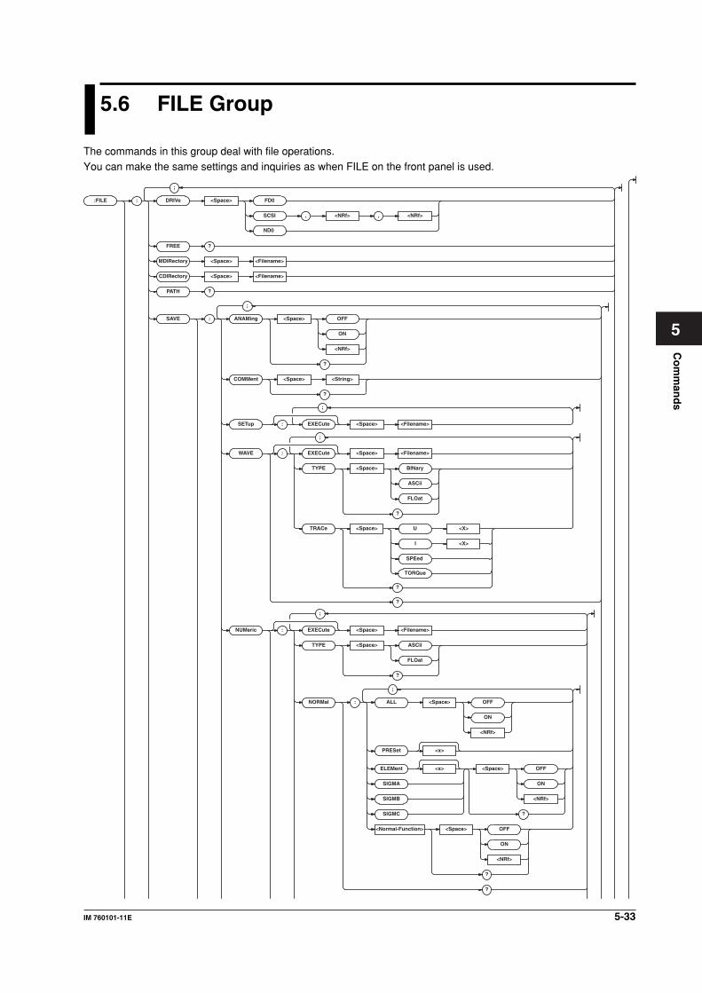
5-33IM 760101-11E
Co
mm
and
s
5
5.6 FILE Group
The commands in this group deal with file operations.You can make the same settings and inquiries as when FILE on the front panel is used.
:FILE :
;
DRIVe <Space> FD0
SCSI
ND0
, <NRf> , <NRf>
FREE ?
MDIRector y <Space> <Filename>
CDIRector y <Space> <Filename>
PA TH ?
SAVE : ANAMing <Space> OFF
ON
<NRf>
?
COMMent <Space> <String>
?
SETup : EXECute <Space> <Filename>
WAVE : EXECute <Space> <Filename>
TYPE <Space> BINar y
ASCii
FLOat
?
?
NUMeric : EXECute <Space> <Filename>
<X>
<X>
TYPE <Space> ASCii
FLOat
?
NORMal : ALL <Space> OFF
ON
<NRf>
PRESet <x>
ELEMent <x> <Space> OFF
ON
<NRf>
?
SIGMA
SIGMB
SIGMC
<Normal-Function> <Space> OFF
ON
<NRf>
?
?
;
;
;
;
;
TRACe <Space> U
I
SPEed
?
TORQue
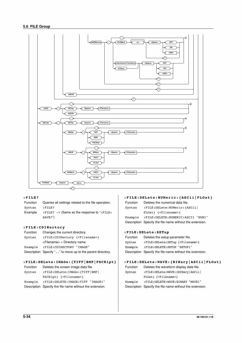
5-34 IM 760101-11E
LOAD : SETup <Space> <Filename>
ABORt
DELete : SETup <Space> <Filename>
IMAGe : TIFF <Space> <Filename>
BMP
PSCRipt
WAVE : BINar y <Space> <Filename>
ASCii
FLOat
NUMeric : ASCii <Space> <Filename>
FLOat
FORMat <Space> HD14
?
;
;
;
;
;
HARMonics : ELEMent <x> <Space> OFF
ON
<NRf>
?
<Harmonics-Function> <Space> OFF
ON
<NRf>
?
OTHers
?
?
ABORt
;
?
:FILE?
Function Queries all settings related to the file operation.
Syntax :FILE?
Example :FILE? -> (Same as the response to “:FILE:
SAVE?”)
:FILE:CDIRectory
Function Changes the current directory.
Syntax :FILE:CDIRectory {<Filename>}
<Filename> = Directory name
Example :FILE:CDIRECTORY "IMAGE"
Description Specify “..” to move up to the parent directory.
:FILE:DELete:IMAGe:{TIFF|BMP|PSCRipt}
Function Deletes the screen image data file.
Syntax :FILE:DELete:IMAGe:{TIFF|BMP|
PSCRipt} {<Filename>}
Example :FILE:DELETE:IMAGE:TIFF "IMAGE1"
Description Specify the file name without the extension.
:FILE:DELete:NUMeric:{ASCii|FLOat}
Function Deletes the numerical data file.
Syntax :FILE:DELete:NUMeric:{ASCii|
FLOat} {<Filename>}
Example :FILE:DELETE:NUMERIC:ASCII "NUM1"
Description Specify the file name without the extension.
:FILE:DELete:SETup
Function Deletes the setup parameter file.
Syntax :FILE:DELete:SETup {<Filename>}
Example :FILE:DELETE:SETUP "SETUP1"
Description Specify the file name without the extension.
:FILE:DELete:WAVE:{BINary|ASCii|FLOat}
Function Deletes the waveform display data file.
Syntax :FILE:DELete:WAVE:{BINary|ASCii|
FLOat} {<Filename>}
Example :FILE:DELETE:WAVE:BINARY "WAVE1"
Description Specify the file name without the extension.
5.6 FILE Group
5-35IM 760101-11E
Co
mm
and
s
5
:FILE:DRIVe
Function Sets the target drive.
Syntax :FILE:DRIVe {FD0|
SCSI,<NRf>[,<NRf>]|ND0}
FD0 = Floppy disk
SCSI = SCSI device
1st <NRf> = SCSI address (0 to 7)
2nd <NRf> = Partition (0 to 9)
ND0 = Network drive
Example :FILE:DRIVE FD0
Description If the drive does not contain partitions, omit the
2nd <NRf>.
:FILE:FORMat
Function Executes the floppy disk format.
Syntax :FILE:FORMat {HD14}
Example :FILE:FORMAT HD14
:FILE:FREE?
Function Queries the free space (bytes) on the target
drive.
Syntax :FILE:FREE?
Example :FILE:FREE? -> 163840
:FILE:LOAD:ABORt
Function Aborts file loading.
Syntax :FILE:LOAD:ABORt
Example :FILE:LOAD:ABORT
:FILE:LOAD:SETup
Function Loads the setup parameter file.
Syntax :FILE:LOAD:SETup {<Filename>}
Example :FILE:LOAD:SETUP "SETUP1"
Description • Specify the file name without the extension.
• This is an overlap command.
:FILE:MDIRectory
Function Creates the directory.
Syntax :FILE:MDIRectory {<Filename>}
<Filename> = Directory name
Example :FILE:MDIRECTORY "TEST"
:FILE:PATH?
Function Queries the absolute path of the current
directory.
Syntax :FILE:PATH?
Example :FILE:PATH? -> "FD0\IMAGE"
:FILE:SAVE?
Function Queries all settings related to the saving of files.
Syntax :FILE:SAVE?
Example :FILE:SAVE? -> :FILE:SAVE:
ANAMING 1;COMMENT "";WAVE:
TYPE BINARY;:FILE:SAVE:NUMERIC:
TYPE ASCII;NORMAL:ELEMENT1 1;
ELEMENT2 0;ELEMENT3 0;ELEMENT4 0;
ELEMENT5 0;ELEMENT6 0;SIGMA 0;
SIGMB 0;SIGMC 0;URMS 1;UMN 1;UDC 1;
UAC 1;IRMS 1;IMN 1;IDC 1;IAC 1;P 1;
S 1;Q 1;LAMBDA 1;PHI 1;FU 1;FI 1;
UPPEAK 1;UMPEAK 1;IPPEAK 1;
IMPEAK 1;CFU 1;CFI 1;FFU 1;FFI 1;
Z 1;RS 1;XS 1;RP 1;XP 1;PC 1;
TIME 0;WH 0;WHP 0;WHM 0;AH 0;AHP 0;
AHM 0;ETA 0;SETA 0;F1 0;F2 0;F3 0;
F4 0;DURMS 0;DUMN 0;DUDC 0;DUAC 0;
DIRMS 0;DIMN 0;DIDC 0;DIAC 0
:FILE:SAVE:ABORt
Function Aborts file saving.
Syntax :FILE:SAVE:ABORt
Example :FILE:SAVE:ABORT
:FILE:SAVE:ANAMing
Function Sets whether to automatically name the files to
be saved or queries the current setting.
Syntax :FILE:SAVE:ANAMing {<Boolean>}
:FILE:SAVE:ANAMing?
Example :FILE:SAVE:ANAMING ON
:FILE:SAVE:ANAMING? -> :FILE:SAVE:
ANAMING 1
:FILE:SAVE:COMMent
Function Sets the comment to be added to the file to be
saved or queries the current setting.
Syntax :FILE:SAVE:COMMent {<String>}
:FILE:SAVE:COMMent?
<string> = 30 characters or less
Example :FILE:SAVE:COMMENT "CASE1"
:FILE:SAVE:COMMENT? -> :FILE:SAVE:
COMMENT "CASE1"
5.6 FILE Group
5-36 IM 760101-11E
:FILE:SAVE:NUMeric?
Function Queries all settings related to the saving of
numerical data files.
Syntax :FILE:SAVE:NUMeric?
Example :FILE:SAVE:NUMERIC? ->
:FILE:SAVE:NUMERIC:TYPE ASCII;
NORMAL:ELEMENT1 1;ELEMENT2 0;
ELEMENT3 0;ELEMENT4 0;ELEMENT5 0;
ELEMENT6 0;SIGMA 0;SIGMB 0;SIGMC 0;
URMS 1;UMN 1;UDC 1;UAC 1;IRMS 1;
IMN 1;IDC 1;IAC 1;P 1;S 1;Q 1;
LAMBDA 1;PHI 1;FU 1;FI 1;UPPEAK 1;
UMPEAK 1;IPPEAK 1;IMPEAK 1;CFU 1;
CFI 1;FFU 1;FFI 1;Z 1;RS 1;XS 1;
RP 1;XP 1;PC 1;TIME 0;WH 0;WHP 0;
WHM 0;AH 0;AHP 0;AHM 0;ETA 0;
SETA 0;F1 0;F2 0;F3 0;F4 0;DURMS 0;
DUMN 0;DUDC 0;DUAC 0;DIRMS 0;
DIMN 0;DIDC 0;DIAC 0
:FILE:SAVE:NUMeric[:EXECute]
Function Saves the numerical data to a file.
Syntax :FILE:SAVE:NUMeric
[:EXECute] {<Filename>}
Example :FILE:SAVE:NUMERIC:EXECUTE "NUM1"
Description • Specify the file name without the extension.
• This is an overlap command.
:FILE:SAVE:NUMeric:HARMonics?
Function Queries all settings related to the saving of
numerical data list files for harmonic
measurement.
Syntax :FILE:SAVE:NUMeric:HARMonics?
Example :FILE:SAVE:NUMERIC:HARMONICS? ->
:FILE:SAVE:NUMERIC:HARMONICS:
ELEMENT1 1;ELEMENT2 0;ELEMENT3 0;
ELEMENT4 0;ELEMENT5 0;ELEMENT6 0;
U 1;I 0;P 0;S 0;Q 0;LAMBDA 0;PHI 0;
PHIU 0;PHII 0;Z 0;RS 0;XS 0;RP 0;
XP 0;OTHERS 0
:FILE:SAVE:NUMeric:HARMonics:ELEMent<x>
Function Turns ON/OFF the output of the element when
saving the numerical data list file during
harmonic measurement or queries the current
setting.
Syntax :FILE:SAVE:NUMeric:HARMonics:
ELEMent<x> {<Boolean>}
:FILE:SAVE:NUMeric:HARMonics:
ELEMent<x>?
<x> = 1 to 6
Example :FILE:SAVE:NUMERIC:HARMONICS:
ELEMENT1 ON
:FILE:SAVE:NUMERIC:HARMONICS:
ELEMENT1? -> :FILE:SAVE:NUMERIC:
HARMONICS:ELEMENT1 1
:FILE:SAVE:NUMeric:HARMonics:{<Harmonic
measurement function>|OTHers}
Function Turns ON/OFF the output of the function when
saving the numerical data list file during
harmonic measurement or queries the current
setting.
Syntax :FILE:SAVE:NUMeric:HARMonics:
{<Harmonic measurement function>|
OTHers} {<Boolean>}
:FILE:SAVE:NUMeric:HARMonics:
{<Harmonic measurement function>|
OTHers}?
<Harmonic measurement function> = {U|I|P|
S|Q|LAMBda...} (See the function selection
list (3) of “DISPlay group.”)
Example :FILE:SAVE:NUMERIC:HARMONICS:U ON
:FILE:SAVE:NUMERIC:HARMONICS:U? ->
:FILE:SAVE:NUMERIC:HARMONICS:U 1
Description The command and query using “:FILE:SAVE:
NUMeric:HARMonics:OTHers” is valid on
models with two or more elements.
:FILE:SAVE:NUMeric:NORMal?
Function Queries all settings related to the saving of
numerical data files for normal measurement.
Syntax :FILE:SAVE:NUMeric:NORMal?
Example :FILE:SAVE:NUMERIC:NORMAL? ->
:FILE:SAVE:NUMERIC:NORMAL:
ELEMENT1 1;ELEMENT2 0;ELEMENT3 0;
ELEMENT4 0;ELEMENT5 0;ELEMENT6 0;
SIGMA 0;SIGMB 0;SIGMC 0;URMS 1;
UMN 1;UDC 1;UAC 1;IRMS 1;IMN 1;
IDC 1;IAC 1;P 1;S 1;Q 1;LAMBDA 1;
PHI 1;FU 1;FI 1;UPPEAK 1;UMPEAK 1;
IPPEAK 1;IMPEAK 1;CFU 1;CFI 1;
FFU 1;FFI 1;Z 1;RS 1;XS 1;RP 1;
XP 1;PC 1;TIME 0;WH 0;WHP 0;WHM 0;
AH 0;AHP 0;AHM 0;ETA 0;SETA 0;F1 0;
F2 0;F3 0;F4 0;DURMS 0;DUMN 0;
DUDC 0;DUAC 0;DIRMS 0;DIMN 0;
DIDC 0;DIAC 0
:FILE:SAVE:NUMeric:NORMal:ALL
Function Collectively turns ON/OFF the output of all
elements and functions when saving the
numerical data file during normal measurement.
Syntax :FILE:SAVE:NUMeric:NORMal:
ALL {<Boolean>}
Example :FILE:SAVE:NUMERIC:NORMAL:ALL ON
5.6 FILE Group
5-37IM 760101-11E
Co
mm
and
s
5
:FILE:SAVE:NUMeric:NORMal:{ELEMent<x>|
SIGMA|SIGMB|SIGMC}
Function Turns ON/OFF the output of the
{element|ΣA|ΣB|ΣC} when saving the numerical
data to a file during normal measurement or
queries the current setting.
Syntax :FILE:SAVE:NUMeric:NORMal:
{ELEMent<x>|SIGMA|SIGMB|
SIGMC} {<Boolean>}
:FILE:SAVE:NUMeric:NORMal:
{ELEMent<x>|SIGMA|SIGMB|SIGMC}?
<x> = 1 to 6
Example :FILE:SAVE:NUMERIC:NORMAL:
ELEMENT1 ON
:FILE:SAVE:NUMERIC:NORMAL:
ELEMENT1? -> :FILE:SAVE:NUMERIC:
NORMAL:ELEMENT1 1
Description • The command and query using “:FILE:
SAVE:NUMeric:NORMal:SIGMB” is valid on
models with two or more elements.
• The command and query using “:FILE:
SAVE:NUMeric:NORMal:SIGMC” is valid on
models with three or more elements.
:FILE:SAVE:NUMeric:NORMal:PRESet<x>
Function Presets the output ON/OFF pattern of the
element and function when saving the numerical
data to a file during normal measurement.
Syntax :FILE:SAVE:NUMeric:NORMal:PRESet<x>
<x> = 1 to 2 (preset pattern number)
Example :FILE:SAVE:NUMERIC:NORMAL:PRESET1
Description For details on the output pattern when preset is
executed, see the WT1600 User’s Manual.
:FILE:SAVE:NUMeric:NORMal:<Normal
measurement function>
Function Turns ON/OFF the output of the function when
saving the numerical data file during normal
measurement or queries the current setting.
Syntax :FILE:SAVE:NUMeric:NORMal:<Normal
measurement function> {<Boolean>}
:FILE:SAVE:NUMeric:NORMal:<Normal
measurement function>?
<Normal measurement function> = {URMS|
UMN|UDC|UAC|IRMS|...} (See the function
selection list (1) of “DISPlay group.”)
Example :FILE:SAVE:NUMERIC:NORMAL:URMS ON
:FILE:SAVE:NUMERIC:NORMAL:URMS? ->
:FILE:SAVE:NUMERIC:NORMAL:URMS 1
:FILE:SAVE:NUMeric:TYPE
Function Sets the format of the numerical data to be
saved or queries the current setting.
Syntax :FILE:SAVE:NUMeric:TYPE {ASCii|
FLOat}
:FILE:SAVE:NUMeric:TYPE?
Example :FILE:SAVE:NUMERIC:TYPE ASCII
:FILE:SAVE:NUMERIC:TYPE? ->
:FILE:SAVE:NUMERIC:TYPE ASCII
:FILE:SAVE:SETup[:EXECute]
Function Saves of the setup parameter file.
Syntax :FILE:SAVE:SETup
[:EXECute] {<Filename>}
Example :FILE:SAVE:SETUP:EXECUTE "SETUP1"
Description • Specify the file name without the extension.
• This is an overlap command.
:FILE:SAVE:WAVE?
Function Queries all settings related to the saving of
waveform display data files.
Syntax :FILE:SAVE:WAVE?
Example :FILE:SAVE:WAVE? -> :FILE:SAVE:
WAVE:TYPE BINARY
:FILE:SAVE:WAVE[:EXECute]
Function Executes the saving of the waveform display
data file.
Syntax :FILE:SAVE:WAVE
[:EXECute] {<Filename>}
Example :FILE:SAVE:WAVE:EXECUTE "WAVE1"
Description • Specify the file name without the extension.
• This is an overlap command.
:FILE:SAVE:WAVE:TRACe
Function Sets the waveform to be saved to a file or
queries the current setting.
Syntax :FILE:SAVE:WAVE:TRACe {U<x>|I<x>|
SPEed|TORQue}
:FILE:SAVE:WAVE:TRACe?
<x> = 1 to 6 (element)
Example :FILE:SAVE:WAVE:TRACE U1
:FILE:SAVE:WAVE:TRACE? -> :FILE:
SAVE:WAVE:TRACE U1
Description • This command is valid when the format of the
waveform display data to be saved (:FILE:
SAVE:WAVE:TYPE) is “FLOat.” When it is
{BINary|ASCii}, all waveforms of which
the display is turned ON are saved.
• {SPEed|TORQue} is valid only when the
motor evaluation function (/MTR option) is
installed.
5.6 FILE Group
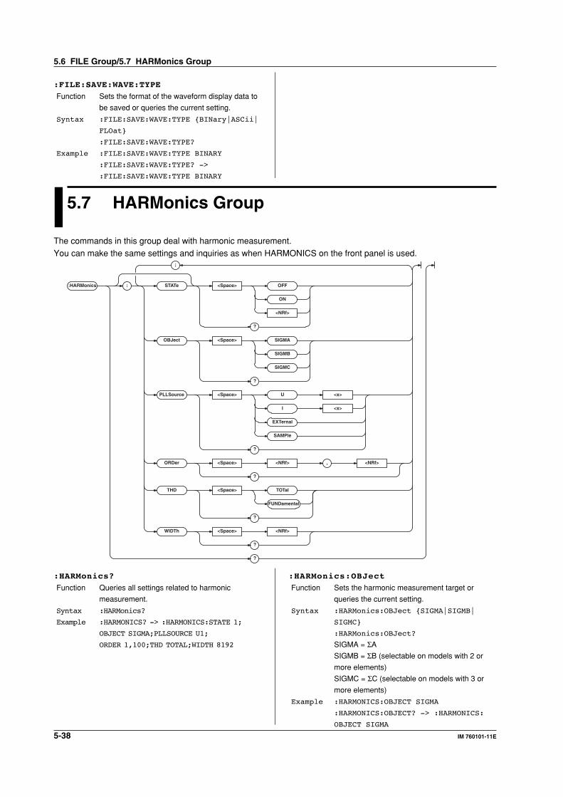
5-38 IM 760101-11E
:FILE:SAVE:WAVE:TYPE
Function Sets the format of the waveform display data to
be saved or queries the current setting.
Syntax :FILE:SAVE:WAVE:TYPE {BINary|ASCii|
FLOat}
:FILE:SAVE:WAVE:TYPE?
Example :FILE:SAVE:WAVE:TYPE BINARY
:FILE:SAVE:WAVE:TYPE? ->
:FILE:SAVE:WAVE:TYPE BINARY
5.7 HARMonics Group
The commands in this group deal with harmonic measurement.
You can make the same settings and inquiries as when HARMONICS on the front panel is used.
:HARMonics :
;
STAT e <Space> OFF
ON
<NRf>
?
OBJect <Space> SIGMA
SIGMB
SIGMC
?
PLLSource <Space> U <x>
I <x>
EXTernal
SAMPle
?
ORDer <Space> <NRf> , <NRf>
?
THD <Space> TOTal
FUNDamental
?
WIDTh <Space> <NRf>
?
?
:HARMonics?
Function Queries all settings related to harmonic
measurement.
Syntax :HARMonics?
Example :HARMONICS? -> :HARMONICS:STATE 1;
OBJECT SIGMA;PLLSOURCE U1;
ORDER 1,100;THD TOTAL;WIDTH 8192
:HARMonics:OBJect
Function Sets the harmonic measurement target or
queries the current setting.
Syntax :HARMonics:OBJect {SIGMA|SIGMB|
SIGMC}
:HARMonics:OBJect?
SIGMA = ΣA
SIGMB = ΣB (selectable on models with 2 or
more elements)
SIGMC = ΣC (selectable on models with 3 or
more elements)
Example :HARMONICS:OBJECT SIGMA
:HARMONICS:OBJECT? -> :HARMONICS:
OBJECT SIGMA
5.6 FILE Group/5.7 HARMonics Group
5-39IM 760101-11E
Co
mm
and
s
5
:HARMonics:ORDer
Function Sets the maximum and minimum orders to be
analyzed or queries the current setting.
Syntax :HARMonics:ORDer {<NRf>,<NRf>}
:HARMonics:ORDer?
1st <NRf> = 0 or 1 (minimum order to be
analyzed)
2nd <NRf> = 1 to 100 (maximum order to be
analyzed)
Example :HARMONICS:ORDER 1,100
:HARMONICS:ORDER? -> :HARMONICS:
ORDER 1,100
:HARMonics:PLLSource
Function Sets the PLL source or queries the current
setting.
Syntax :HARMonics:PLLSource {U<x>|I<x>|
EXTernal|SAMPle}
:HARMonics:PLLSource?
<x> = 1 to 6 (element)
EXTernal = External clock input (Ext Clk)
SAMPle = Sampling clock input (Smp Clk)
Example :HARMONICS:PLLSOURCE U1
:HARMONICS:PLLSOURCE? ->:HARMONICS:
PLLSOURCE U1
:HARMonics[:STATe]
Function Turns ON/OFF the harmonic measurement
mode or queries the current setting.
Syntax :HARMonics[:STATe] {<Boolean>}
:HARMonics:STATe?
Example :HARMONICS:STATE ON
:HARMONICS:STATE? -> :HARMONICS:
STATE 1
:HARMonics:THD
Function Sets the equation used to calculate the THD
(total harmonic distortion) or queries the current
setting.
Syntax :HARMonics:THD {TOTal|FUNDamental}
:HARMonics:THD?
Example :HARMONICS:THD TOTAL
:HARMONICS:THD? -> :HARMONICS:
THD TOTAL
:HARMonics:WIDTh
Function Sets the data length used during harmonic
measurement or queries the current setting.
Syntax :HARMonics:WIDTh {<NRf>}
:HARMonics:WIDTh?
<NRf> = 2048, 4096, 8192
Example :HARMONICS:WIDTH 8192
:HARMONICS:WIDTH? -> :HARMONICS:
WIDTH 8192
5.7 HARMonics Group
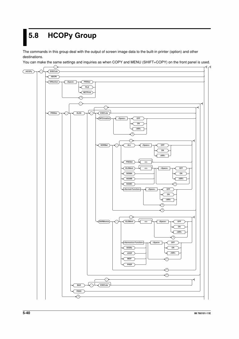
5-40 IM 760101-11E
5.8 HCOPy Group
The commands in this group deal with the output of screen image data to the built-in printer (option) and otherdestinations.
You can make the same settings and inquiries as when COPY and MENU (SHIFT+COPY) on the front panel is used.
:HCOPy :
;
EXECute
ABORt
DIRection <Space> PRINter
FILE
NETPrint
?
PRINter : DLISt : EXECute
INFOrmation <Space> OFF
ON
<NRf>
?
NORMal : ALL <Space> OFF
ON
<NRf>
PRESet <x>
ELEMent <x> <Space> OFF
ON
<NRf>
?
SIGMA
SIGMB
SIGMC
<Normal-Function> <Space> OFF
ON
<NRf>
?
?
HARMonics : ELEMent <x> <Space> OFF
ON
<NRf>
?
<Harmonics-Function> <Space> OFF
ON
<NRf>
?
SIGMa
?
?
BAR : EXECute
FEED
?
;
;
;
;
UHDF
IMDF
PHDF
;
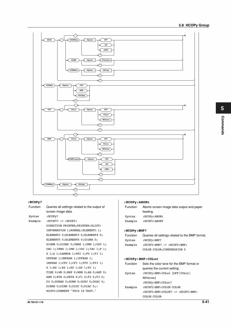
5-41IM 760101-11E
Co
mm
and
s
5
SAVE : ANAMing <Space> OFF
ON
<NRf>
?
NAME <Space> <Filename>
?
COMMent <Space> <String>
?
?
FORMat <Space> TIFF
BMP
PSCRipt
?
TIFF : COLor <Space> OFF
COLor
REVerse
?
?
BMP : COLor <Space> OFF
COLor
REVerse
?
COMPression <Space> OFF
ON
<NRf>
?
?
COMMent <Space> <String>
?
?
;
;
;
:HCOPy?
Function Queries all settings related to the output of
screen image data.
Syntax :HCOPy?
Example :HCOPY? -> :HCOPY:
DIRECTION PRINTER;PRINTER:DLIST:
INFORMATION 1;NORMAL:ELEMENT1 1;
ELEMENT2 0;ELEMENT3 0;ELEMENT4 0;
ELEMENT5 0;ELEMENT6 0;SIGMA 0;
SIGMB 0;SIGMC 0;URMS 1;UMN 1;UDC 1;
UAC 1;IRMS 1;IMN 1;IDC 1;IAC 1;P 1;
S 1;Q 1;LAMBDA 1;PHI 1;FU 1;FI 1;
UPPEAK 1;UMPEAK 1;IPPEAK 1;
IMPEAK 1;CFU 1;CFI 1;FFU 1;FFI 1;
Z 1;RS 1;XS 1;RP 1;XP 1;PC 1;
TIME 0;WH 0;WHP 0;WHM 0;AH 0;AHP 0;
AHM 0;ETA 0;SETA 0;F1 0;F2 0;F3 0;
F4 0;DURMS 0;DUMN 0;DUDC 0;DUAC 0;
DIRMS 0;DIMN 0;DIDC 0;DIAC 0;:
HCOPY:COMMENT "THIS IS TEST."
:HCOPy:ABORt
Function Aborts screen image data output and paper
feeding.
Syntax :HCOPy:ABORt
Example :HCOPY:ABORT
:HCOPy:BMP?
Function Queries all settings related to the BMP format.
Syntax :HCOPy:BMP?
Example :HCOPY:BMP? -> :HCOPY:BMP:
COLOR COLOR;COMPRESSION 0
:HCOPy:BMP:COLor
Function Sets the color tone for the BMP format or
queries the current setting.
Syntax :HCOPy:BMP:COLor {OFF|COLor|
REVerse}
:HCOPy:BMP:COLor?
Example :HCOPY:BMP:COLOR COLOR
:HCOPY:BMP:COLOR? -> :HCOPY:BMP:
COLOR COLOR
5.8 HCOPy Group
5-42 IM 760101-11E
:HCOPy:BMP:COMPression
Function Sets whether to compress the data in BMP
format or queries the current setting.
Syntax :HCOPy:BMP:COMPression {<Boolean>}
:HCOPy:BMP:COMPression?
Example :HCOPY:BMP:COMPRESSION OFF
:HCOPY:BMP:COMPRESSION? -> :HCOPY:
BMP:COMPRESSION 0
Description This command is valid when the color tone
(:HCOPy:BMP:COLor) is set to {COLor|
REVerse}.
:HCOPy:COMMent
Function Sets the comment displayed at the bottom of
the screen or queries the current setting.
Syntax :HCOPy:COMMent {<String>}
:HCOPy:COMMent?
<String > = 25 characters or less (However, only
the first 20 characters are displayed.)
Example :HCOPY:COMMENT "THIS IS TEST."
:HCOPY:COMMENT? -> :HCOPY:
COMMENT "THIS IS TEST."
Description Only the characters and symbols displayed on
the keyboard on the screen can be used.
:HCOPy:DIRection
Function Sets the output destination of the screen image
data or queries the current setting.
Syntax :HCOPy:DIRection {PRINter|FILE|
NETPrint}
:HCOPy:DIRection?
Example :HCOPY:DIRECTION PRINTER
:HCOPY:DIRECTION? -> :HCOPY:
DIRECTION PRINTER
Description • {PRINTer} is valid only when the built-in
printer (/B5 option) is installed.
• {NETPrint} is valid only when the Ethernet
interface (/C10 option) is installed.
:HCOPy:EXECute
Function Executes the screen image data output. This is
an overlap command.
Syntax :HCOPy:EXECute
Example :HCOPY:EXECUTE
Description This is an overlap command.
:HCOPy:FORMat
Function Sets the file format of the screen image data to
be saved or queries the current setting.
Syntax :HCOPy:FORMat {TIFF|BMP|PSCRipt}
:HCOPy:FORMat?
Example :HCOPY:FORMAT TIFF
:HCOPY:FORMAT? -> :HCOPY:
FORMAT TIFF
Description This command is meaningless if the data output
destination (:HCOPy:DIRection) is set to
“PRINter.”
:HCOPy:PRINter?
Function Queries all settings related to the built-in printer
output.
Syntax :HCOPy:PRINter?
Example :HCOPY:PRINTER? -> (Same as the
response to “:HCOPy:PRINter:DLISt?”)
:HCOPy:PRINter:BAR[:EXECute]
Function Executes printing of the bar graph for harmonic
measurement using the built-in printer. This is
an overlap command.
Syntax :HCOPy:PRINter:BAR[:EXECute]
Example :HCOPY:PRINTER:BAR:EXECUTE
Description • Valid only during harmonic measurement.
• This is an overlap command.
:HCOPy:PRINter:DLISt?
Function Queries all settings related to the printing of the
numerical data list using the built-in printer.
Syntax :HCOPy:PRINter:DLISt?
Example :HCOPY:PRINTER:DLIST? ->
:HCOPY:PRINTER:DLIST:INFORMATION 1;
NORMAL:ELEMENT1 1;ELEMENT2 0;
ELEMENT3 0;ELEMENT4 0;ELEMENT5 0;
ELEMENT6 0;SIGMA 0;SIGMB 0;SIGMC 0;
URMS 1;UMN 1;UDC 1;UAC 1;IRMS 1;
IMN 1;IDC 1;IAC 1;P 1;S 1;Q 1;
LAMBDA 1;PHI 1;FU 1;FI 1;UPPEAK 1;
UMPEAK 1;IPPEAK 1;IMPEAK 1;CFU 1;
CFI 1;FFU 1;FFI 1;Z 1;RS 1;XS 1;
RP 1;XP 1;PC 1;TIME 0;WH 0;WHP 0;
WHM 0;AH 0;AHP 0;AHM 0;ETA 0;
SETA 0;F1 0;F2 0;F3 0;F4 0;DURMS 0;
DUMN 0;DUDC 0;DUAC 0;DIRMS 0;
DIMN 0;DIDC 0;DIAC 0
:HCOPy:PRINter:DLISt[:EXECute]
Function Prints of the numerical data list using the built-in
printer.
Syntax :HCOPy:PRINter:DLISt[:EXECute]
Example :HCOPY:PRINTER:DLIST:EXECUTE
Description This is an overlap command.
:HCOPy:PRINter:DLISt:HARMonics?
Function Queries all settings related to the printing of the
numerical data list for harmonic measurement.
Syntax :HCOPy:PRINter:DLISt:HARMonics?
Example :HCOPY:PRINTER:DLIST:HARMONICS? ->
:HCOPY:PRINTER:DLIST:HARMONICS:
ELEMENT1 1;ELEMENT2 0;ELEMENT3 0;
ELEMENT4 0;ELEMENT5 0;ELEMENT6 0;
U 1;I 0;P 0;S 0;Q 0;LAMBDA 0;PHI 0;
PHIU 0;PHII 0;Z 0;RS 0;XS 0;RP 0;
XP 0;SIGMA 0;UHDF 0;IHDF 0;PHDF 0
5.8 HCOPy Group
5-43IM 760101-11E
Co
mm
and
s
5
:HCOPy:PRINter:DLISt:HARMonics:
ELEMent<x>
Function Turns ON/OFF the output of the element when
printing the numerical data list using the built-in
printer during harmonic measurement or queries
the current setting.
Syntax :HCOPy:PRINter:DLISt:HARMonics:
ELEMent<x> {<Boolean>}
:HCOPy:PRINter:DLISt:HARMonics:
ELEMent<x>?
<x> = 1 to 6
Example :HCOPY:PRINTER:DLIST:HARMONICS:
ELEMENT1 ON
:HCOPY:PRINTER:DLIST:HARMONICS:
ELEMENT1? -> :HCOPY:PRINTER:DLIST:
HARMONICS:ELEMENT1 1
:HCOPy:PRINter:DLISt:HARMonics:
{<Harmonic measurement function>|SIGMa|
UHDF|IHDF|PHDF}
Function Turns ON/OFF the output of the function when
printing the numerical data list using the built-in
printer during harmonic measurement or queries
the current setting.
Syntax :HCOPy:PRINter:DLISt:HARMonics:
{<Harmonic measurement function>|
SIGMa|UHDF|IHDF|PHDF} {<Boolean>}
:HCOPy:PRINter:DLISt:HARMonics:
{<Harmonic measurement function>|
SIGMa|UHDF|IHDF|PHDF}?
<Harmonic measurement function> = {U|I|P|
S|Q|LAMBda...} (See the function selection
list (3) of “DISPlay group.”)
SIGMa = ΣList (dedicated to numerical data list
printing)
UHDF = Uhdf (dedicated to bar graph printing)
IHDF = Ihdf (dedicated to bar graph printing)
PHDF = Phdf (dedicated to bar graph printing)
Example :HCOPY:PRINTER:DLIST:HARMONICS:U ON
:HCOPY:PRINTER:DLIST:HARMONICS:U?
-> :HCOPY:PRINTER:DLIST:HARMONICS:
U 1
Description The command and query using “:HCOPy:
PRINter:DLISt:HARMonics:SIGMa” is valid
on models with two or more elements.
:HCOPy:PRINter:DLISt:INFOrmation
Function Sets whether or not to add setup parameters
when printing the numerical data list using the
built-in printer or queries the current setting.
Syntax :HCOPy:PRINter:DLISt:
INFOrmation {<Boolean>}
:HCOPy:PRINter:DLISt:INFOrmation?
Example :HCOPY:PRINTER:DLIST:INFORMATION ON
:HCOPY:PRINTER:DLIST:INFORMATION?
-> :HCOPY:PRINTER:DLIST:
INFORMATION 1
:HCOPy:PRINter:DLISt:NORMal?
Function Queries all settings related to the printing of the
numerical data list for normal measurement.
Syntax :HCOPy:PRINter:DLISt:NORMal?
Example :HCOPY:PRINTER:DLIST:NORMAL? ->
:HCOPY:PRINTER:DLIST:NORMAL:
ELEMENT1 1;ELEMENT2 0;ELEMENT3 0;
ELEMENT4 0;ELEMENT5 0;ELEMENT6 0;
SIGMA 0;SIGMB 0;SIGMC 0;URMS 1;
UMN 1;UDC 1;UAC 1;IRMS 1;IMN 1;
IDC 1;IAC 1;P 1;S 1;Q 1;LAMBDA 1;
PHI 1;FU 1;FI 1;UPPEAK 1;UMPEAK 1;
IPPEAK 1;IMPEAK 1;CFU 1;CFI 1;
FFU 1;FFI 1;Z 1;RS 1;XS 1;RP 1;
XP 1;PC 1;TIME 0;WH 0;WHP 0;WHM 0;
AH 0;AHP 0;AHM 0;ETA 0;SETA 0;F1 0;
F2 0;F3 0;F4 0;DURMS 0;DUMN 0;
DUDC 0;DUAC 0;DIRMS 0;DIMN 0;
DIDC 0;DIAC 0
:HCOPy:PRINter:DLISt:NORMal:ALL
Function Collectively turns ON/OFF the output of all
elements and functions when printing the
numerical data list using the built-in printer
during normal measurement.
Syntax :HCOPy:PRINter:DLISt:NORMal:
ALL {<Boolean>}
Example :HCOPY:PRINTER:DLIST:NORMAL:ALL ON
:HCOPy:PRINter:DLISt:NORMal:{ELEMent<x>|
SIGMA|SIGMB|SIGMC}
Function Turns ON/OFF the output of the {element|
ΣA|ΣB|ΣC} when printing the numerical data
list using the built-in printer during normal
measurement or queries the current setting.
Syntax :HCOPy:PRINter:DLISt:NORMal:
{ELEMent<x>|SIGMA|SIGMB|
SIGMC} {<Boolean>}
:HCOPy:PRINter:DLISt:NORMal:
{ELEMent<x>|SIGMA|SIGMB|SIGMC}?
<x> = 1 to 6
Example :HCOPY:PRINTER:DLIST:NORMAL:
ELEMENT1 ON
:HCOPY:PRINTER:DLIST:NORMAL:
ELEMENT1? -> :HCOPY:PRINTER:DLIST:
NORMAL:ELEMENT1 1
Description • The command and query using “:HCOPy:
PRINter:DLISt:NORMal:SIGMB” is valid
on models with two or more elements.
• The command and query using “:HCOPy:
PRINter:DLISt:NORMal:SIGMC” is valid
on models with three or more elements.
5.8 HCOPy Group
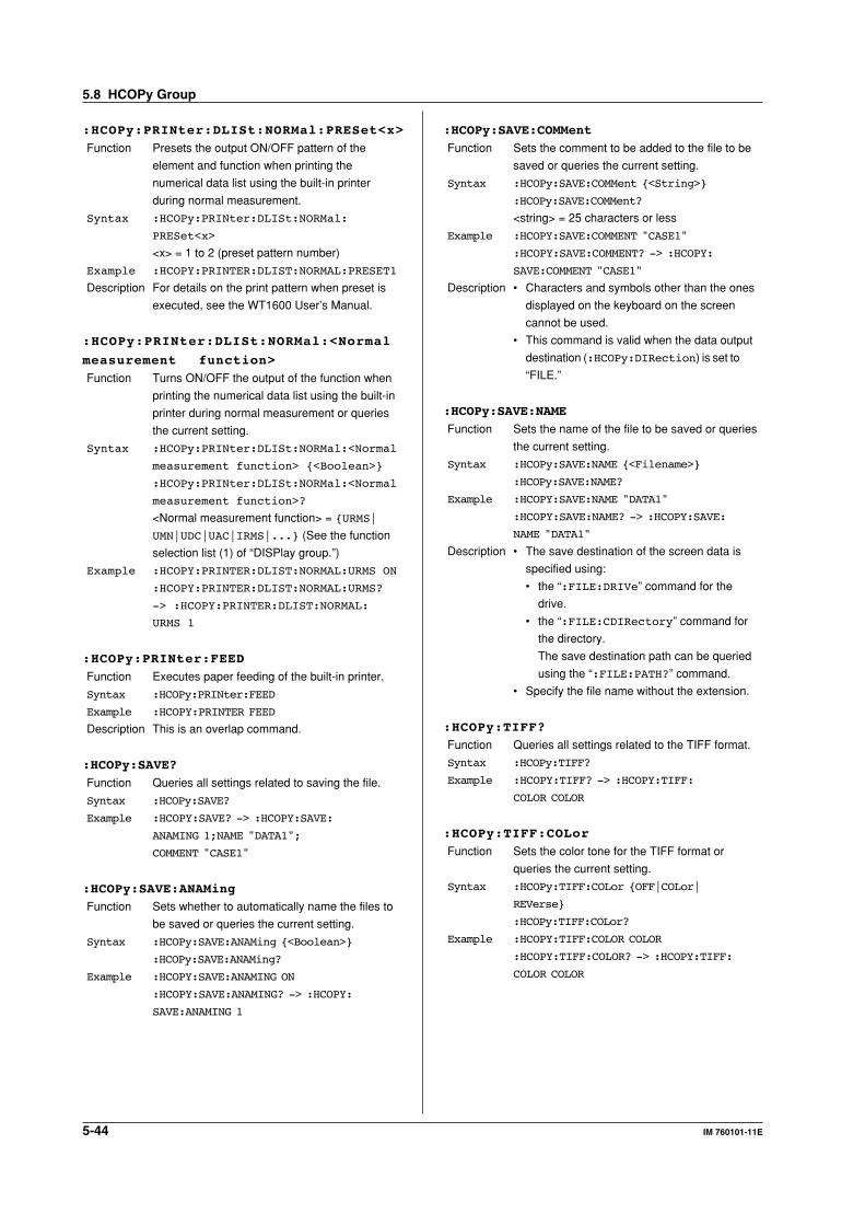
5-44 IM 760101-11E
:HCOPy:PRINter:DLISt:NORMal:PRESet<x>
Function Presets the output ON/OFF pattern of the
element and function when printing the
numerical data list using the built-in printer
during normal measurement.
Syntax :HCOPy:PRINter:DLISt:NORMal:
PRESet<x>
<x> = 1 to 2 (preset pattern number)
Example :HCOPY:PRINTER:DLIST:NORMAL:PRESET1
Description For details on the print pattern when preset is
executed, see the WT1600 User’s Manual.
:HCOPy:PRINter:DLISt:NORMal:<Normal
measurement function>
Function Turns ON/OFF the output of the function when
printing the numerical data list using the built-in
printer during normal measurement or queries
the current setting.
Syntax :HCOPy:PRINter:DLISt:NORMal:<Normal
measurement function> {<Boolean>}
:HCOPy:PRINter:DLISt:NORMal:<Normal
measurement function>?
<Normal measurement function> = {URMS|
UMN|UDC|UAC|IRMS|...} (See the function
selection list (1) of “DISPlay group.”)
Example :HCOPY:PRINTER:DLIST:NORMAL:URMS ON
:HCOPY:PRINTER:DLIST:NORMAL:URMS?
-> :HCOPY:PRINTER:DLIST:NORMAL:
URMS 1
:HCOPy:PRINter:FEED
Function Executes paper feeding of the built-in printer.
Syntax :HCOPy:PRINter:FEED
Example :HCOPY:PRINTER FEED
Description This is an overlap command.
:HCOPy:SAVE?
Function Queries all settings related to saving the file.
Syntax :HCOPy:SAVE?
Example :HCOPY:SAVE? -> :HCOPY:SAVE:
ANAMING 1;NAME "DATA1";
COMMENT "CASE1"
:HCOPy:SAVE:ANAMing
Function Sets whether to automatically name the files to
be saved or queries the current setting.
Syntax :HCOPy:SAVE:ANAMing {<Boolean>}
:HCOPy:SAVE:ANAMing?
Example :HCOPY:SAVE:ANAMING ON
:HCOPY:SAVE:ANAMING? -> :HCOPY:
SAVE:ANAMING 1
:HCOPy:SAVE:COMMent
Function Sets the comment to be added to the file to be
saved or queries the current setting.
Syntax :HCOPy:SAVE:COMMent {<String>}
:HCOPy:SAVE:COMMent?
<string> = 25 characters or less
Example :HCOPY:SAVE:COMMENT "CASE1"
:HCOPY:SAVE:COMMENT? -> :HCOPY:
SAVE:COMMENT "CASE1"
Description • Characters and symbols other than the ones
displayed on the keyboard on the screen
cannot be used.
• This command is valid when the data output
destination (:HCOPy:DIRection) is set to
“FILE.”
:HCOPy:SAVE:NAME
Function Sets the name of the file to be saved or queries
the current setting.
Syntax :HCOPy:SAVE:NAME {<Filename>}
:HCOPy:SAVE:NAME?
Example :HCOPY:SAVE:NAME "DATA1"
:HCOPY:SAVE:NAME? -> :HCOPY:SAVE:
NAME "DATA1"
Description • The save destination of the screen data is
specified using:
• the “:FILE:DRIVe” command for the
drive.
• the “:FILE:CDIRectory” command for
the directory.
The save destination path can be queried
using the “:FILE:PATH?” command.
• Specify the file name without the extension.
:HCOPy:TIFF?
Function Queries all settings related to the TIFF format.
Syntax :HCOPy:TIFF?
Example :HCOPY:TIFF? -> :HCOPY:TIFF:
COLOR COLOR
:HCOPy:TIFF:COLor
Function Sets the color tone for the TIFF format or
queries the current setting.
Syntax :HCOPy:TIFF:COLor {OFF|COLor|
REVerse}
:HCOPy:TIFF:COLor?
Example :HCOPY:TIFF:COLOR COLOR
:HCOPY:TIFF:COLOR? -> :HCOPY:TIFF:
COLOR COLOR
5.8 HCOPy Group
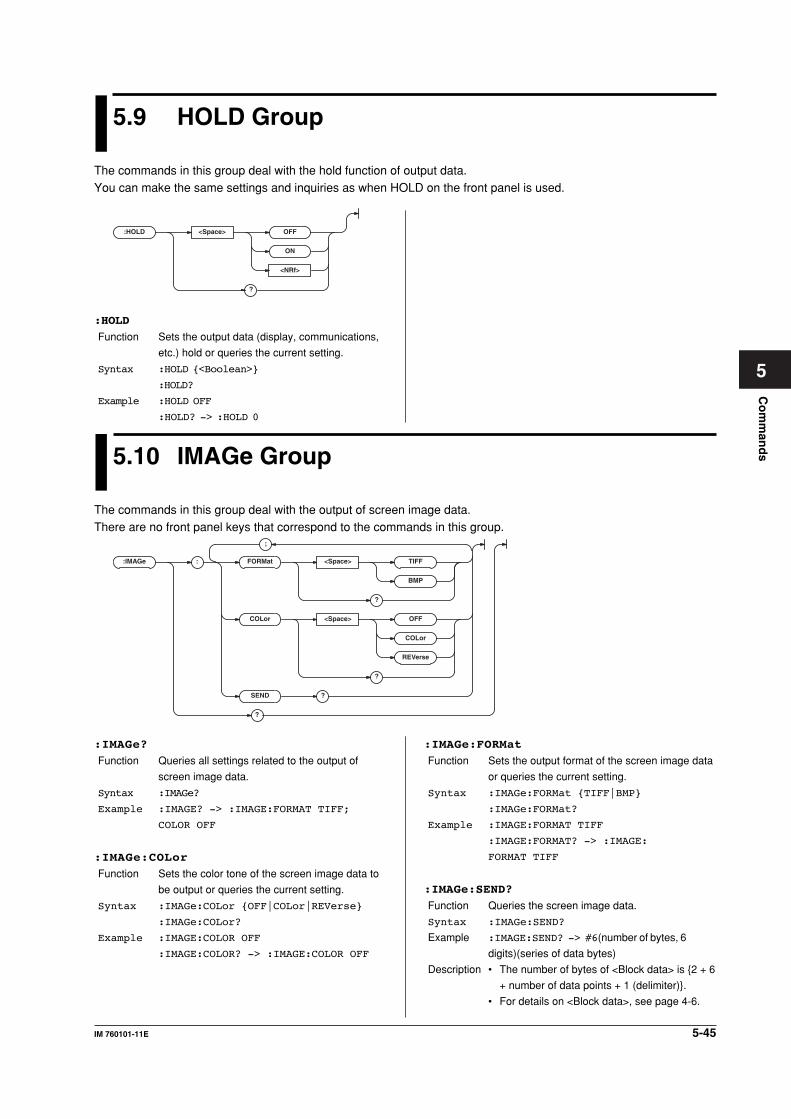
5-45IM 760101-11E
Co
mm
and
s
5
5.9 HOLD Group
The commands in this group deal with the hold function of output data.You can make the same settings and inquiries as when HOLD on the front panel is used.
5.10 IMAGe Group
The commands in this group deal with the output of screen image data.There are no front panel keys that correspond to the commands in this group.
:IMAGe :
;
FORMat <Space> TIFF
BMP
?
COLor <Space> OFF
COLor
REVerse
?
SEND ?
?
:HOLD <Space> OFF
ON
<NRf>
?
:HOLD
Function Sets the output data (display, communications,
etc.) hold or queries the current setting.
Syntax :HOLD {<Boolean>}
:HOLD?
Example :HOLD OFF
:HOLD? -> :HOLD 0
:IMAGe?
Function Queries all settings related to the output of
screen image data.
Syntax :IMAGe?
Example :IMAGE? -> :IMAGE:FORMAT TIFF;
COLOR OFF
:IMAGe:COLor
Function Sets the color tone of the screen image data to
be output or queries the current setting.
Syntax :IMAGe:COLor {OFF|COLor|REVerse}
:IMAGe:COLor?
Example :IMAGE:COLOR OFF
:IMAGE:COLOR? -> :IMAGE:COLOR OFF
:IMAGe:FORMat
Function Sets the output format of the screen image data
or queries the current setting.
Syntax :IMAGe:FORMat {TIFF|BMP}
:IMAGe:FORMat?
Example :IMAGE:FORMAT TIFF
:IMAGE:FORMAT? -> :IMAGE:
FORMAT TIFF
:IMAGe:SEND?
Function Queries the screen image data.
Syntax :IMAGe:SEND?
Example :IMAGE:SEND? -> #6(number of bytes, 6
digits)(series of data bytes)
Description • The number of bytes of <Block data> is {2 + 6
+ number of data points + 1 (delimiter)}.
• For details on <Block data>, see page 4-6.
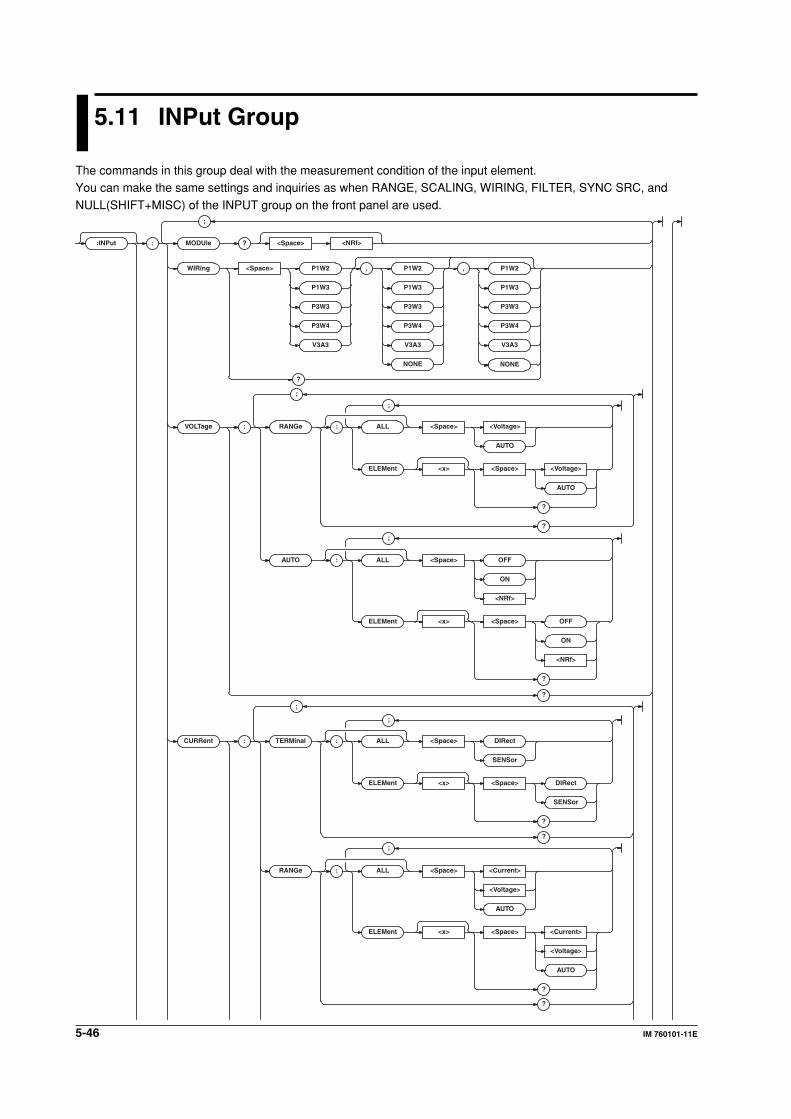
5-46 IM 760101-11E
5.11 INPut Group
The commands in this group deal with the measurement condition of the input element.You can make the same settings and inquiries as when RANGE, SCALING, WIRING, FILTER, SYNC SRC, and
NULL(SHIFT+MISC) of the INPUT group on the front panel are used.
:INPut : MODUle ? <Space> <NRf>
WIRing <Space> P1W2 , P1W2 , P1W2
P1W3
P3W3
P3W4
V3A3
NONE
P1W3
P3W3
P3W4
V3A3
NONE
P1W3
P3W3
P3W4
V3A3
?
VOLT age : RANGe : ALL <Space> <Voltage>
AUTO
ELEMent <x> <Space> <Voltage>
AUTO
?
?
AUTO : ALL <Space> OFF
ON
<NRf>
ELEMent <x> <Space> OFF
ON
<NRf>
?
?
CURRent : TERMinal : ALL <Space> DIRect
SENSor
ELEMent <x> <Space> DIRect
SENSor
?
?
RANGe : ALL <Space> <Current>
<Voltage>
AUTO
ELEMent <x> <Space> <Current>
<Voltage>
AUTO
?
?
;
;
;
;
;
;
;
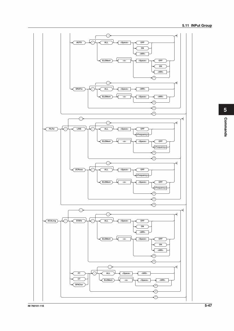
5-47IM 760101-11E
Co
mm
and
s
5
ELEMent <x> <Space> <NRf>
?
?
?
FILTer : LINE : ALL <Space> OFF
<Frequency>
ELEMent <x> <Space> OFF
<Frequency>
?
?
ZCRoss : ALL <Space> OFF
<Frequency>
ELEMent <x> <Space> OFF
<Frequency>
?
?
?
SCALing : STAT e : ALL <Space> OFF
ON
<NRf>
ELEMent <x> <Space> OFF
ON
<NRf>
?
?
PT : ALL <Space> <NRf>
ELEMent <x> <Space> <NRf>
?
?
CT
SFACtor
?
;
;
;
;
;
;
SRATio : ALL <Space> <NRf>
;
AUTO : ALL <Space> OFF
ON
<NRf>
ELEMent <x> <Space> OFF
ON
<NRf>
?
;
5.11 INPut Group
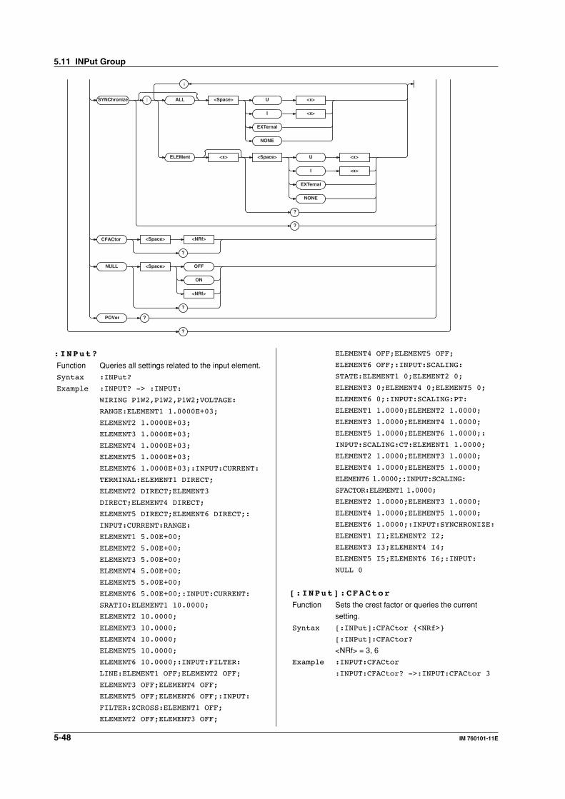
5-48 IM 760101-11E
SYNChroniz e : ALL <Space> U <x>
I <x>
EXTernal
NONE
ELEMent <x> <Space> U <x>
I <x>
EXTernal
NONE
?
?
NULL <Space> OFF
ON
<NRf>
?
?
?
;
POVer
CFACtor <Space>
?
<NRf>
ELEMENT4 OFF;ELEMENT5 OFF;
ELEMENT6 OFF;:INPUT:SCALING:
STATE:ELEMENT1 0;ELEMENT2 0;
ELEMENT3 0;ELEMENT4 0;ELEMENT5 0;
ELEMENT6 0;:INPUT:SCALING:PT:
ELEMENT1 1.0000;ELEMENT2 1.0000;
ELEMENT3 1.0000;ELEMENT4 1.0000;
ELEMENT5 1.0000;ELEMENT6 1.0000;:
INPUT:SCALING:CT:ELEMENT1 1.0000;
ELEMENT2 1.0000;ELEMENT3 1.0000;
ELEMENT4 1.0000;ELEMENT5 1.0000;
ELEMENT6 1.0000;:INPUT:SCALING:
SFACTOR:ELEMENT1 1.0000;
ELEMENT2 1.0000;ELEMENT3 1.0000;
ELEMENT4 1.0000;ELEMENT5 1.0000;
ELEMENT6 1.0000;:INPUT:SYNCHRONIZE:
ELEMENT1 I1;ELEMENT2 I2;
ELEMENT3 I3;ELEMENT4 I4;
ELEMENT5 I5;ELEMENT6 I6;:INPUT:
NULL 0
[:INPut]:CFACtor
Function Sets the crest factor or queries the current
setting.
Syntax [:INPut]:CFACtor {<NRf>}
[:INPut]:CFACtor?
<NRf> = 3, 6
Example :INPUT:CFACtor
:INPUT:CFACtor? ->:INPUT:CFACtor 3
:INPut?
Function Queries all settings related to the input element.
Syntax :INPut?
Example :INPUT? -> :INPUT:
WIRING P1W2,P1W2,P1W2;VOLTAGE:
RANGE:ELEMENT1 1.0000E+03;
ELEMENT2 1.0000E+03;
ELEMENT3 1.0000E+03;
ELEMENT4 1.0000E+03;
ELEMENT5 1.0000E+03;
ELEMENT6 1.0000E+03;:INPUT:CURRENT:
TERMINAL:ELEMENT1 DIRECT;
ELEMENT2 DIRECT;ELEMENT3
DIRECT;ELEMENT4 DIRECT;
ELEMENT5 DIRECT;ELEMENT6 DIRECT;:
INPUT:CURRENT:RANGE:
ELEMENT1 5.00E+00;
ELEMENT2 5.00E+00;
ELEMENT3 5.00E+00;
ELEMENT4 5.00E+00;
ELEMENT5 5.00E+00;
ELEMENT6 5.00E+00;:INPUT:CURRENT:
SRATIO:ELEMENT1 10.0000;
ELEMENT2 10.0000;
ELEMENT3 10.0000;
ELEMENT4 10.0000;
ELEMENT5 10.0000;
ELEMENT6 10.0000;:INPUT:FILTER:
LINE:ELEMENT1 OFF;ELEMENT2 OFF;
ELEMENT3 OFF;ELEMENT4 OFF;
ELEMENT5 OFF;ELEMENT6 OFF;:INPUT:
FILTER:ZCROSS:ELEMENT1 OFF;
ELEMENT2 OFF;ELEMENT3 OFF;
5.11 INPut Group
5-49IM 760101-11E
Co
mm
and
s
5
[:INPut]:CURRent?
Function Queries all settings related to the current
measurement.
Syntax [:INPut]:CURRent?
Example :INPUT:CURRENT? -> :INPUT:CURRENT:
TERMINAL:ELEMENT1 DIRECT;
ELEMENT2 DIRECT;ELEMENT3 DIRECT;
ELEMENT4 DIRECT;ELEMENT5 DIRECT;
ELEMENT6 DIRECT;:INPUT:CURRENT:
RANGE:ELEMENT1 5.00E+00;
ELEMENT2 5.00E+00;
ELEMENT3 5.00E+00;
ELEMENT4 5.00E+00;
ELEMENT5 5.00E+00;
ELEMENT6 5.00E+00;:INPUT:CURRENT:
SRATIO:ELEMENT1 10.0000;
ELEMENT2 10.0000;ELEMENT3 10.0000;
ELEMENT4 10.0000;ELEMENT5 10.0000;
ELEMENT6 10.0000
[:INPut]:CURRent:AUTO[:ALL]
Function Collectively turns ON/OFF the current auto
range of all elements.
Syntax [:INPut]:CURRent:AUTO
[:ALL] {<Boolean>}
Example :INPUT:CURRENT:AUTO:ALL ON
[:INPut]:CURRent:AUTO:ELEMent<x>
Function Turns ON/OFF the current auto range of the
element or queries the current setting.
Syntax [:INPut]:CURRent:AUTO:
ELEMent<x> {<Boolean>}
[:INPut]:CURRent:AUTO:ELEMent<x>?
<x> = 1 to 6
Example :INPUT:CURRENT:AUTO:ELEMENT1 ON
:INPUT:CURRENT:AUTO:ELEMENT1? ->
:INPUT:CURRENT:AUTO:ELEMENT1 1
[:INPut]:CURRent:RANGe?
Function Queries the current ranges of all elements.
Syntax [:INPut]:CURRent:RANGe?
Example :INPUT:CURRENT:RANGE? -> :INPUT:
CURRENT:RANGE:ELEMENT1 5.00E+00;
ELEMENT2 5.00E+00;
ELEMENT3 5.00E+00;
ELEMENT4 5.00E+00;
ELEMENT5 5.00E+00;ELEMENT6 5.00E+00
[:INPut]:CURRent:RANGe[:ALL]
Function Collectively sets the current ranges of all
elements.
Syntax [:INPut]:CURRent:RANGe
[:ALL] {<Current>|<Voltage>|AUTO}
• When the crest factor is set to 3
• For a 5-A input element
<Current> = 10, 20, 50, 100, 200, 500
(mA), 1, 2, 5 (A) (when TERMinal = DIRect)
<Voltage> = 50, 100, 250, 500 (mV), 1, 2.5,
5, 10 (V) (when TERMinal = SENSor)
AUTO = Auto range
• For a 50-A input element
<Current> = 1, 2, 5, 10, 20, 50 (A) (when
TERMinal = DIRect)
<Voltage> = 50, 100, 250, 500 (mV), 1, 2.5,
5, 10 (V) (when TERMinal = SENSor)
AUTO = Auto range
• When the crest factor is set to 6
• For a 5-A input element
<Current> = 5, 10, 25, 50, 100, 250 (mA),
0.5, 1, 2.5 (A) (when TERMinal = DIRect)
<Voltage> = 25, 50, 125, 250 (mV), 0.5,
1.25, 2.5, 5 (V) (when TERMinal = SENSor)
AUTO = Auto range
• For a 50-A input element
<Current> = 0.5, 1, 2.5, 5, 10, 25 (A) (when
TERMinal = DIRect)
<Voltage> = 25, 50, 125, 250 (mV), 0.5,
1.25, 2.5, 5 (V) (when TERMinal = SENSor)
AUTO = Auto range
Example :INPUT:CURRENT:RANGE:ALL 5A
Description The selectable range is determined by the input
element type (5A/50A) of element 1 and the
current measurement terminal setting
([:INPut]:CURRent:TERMinal:ELEMent1).
Therefore, only the elements that are set to the
same input element type and current measurement
terminal setting as element 1 are set.
[:INPut]:CURRent:RANGe:ELEMent<x>
Function Sets the current range of the element or queriesthe current setting.
Syntax [:INPut]:CURRent:RANGe:
ELEMent<x> {<Current>|<Voltage>|
AUTO}
[:INPut]:CURRent:RANGe:ELEMent<x>?
<x> = 1 to 6
• When the crest factor is set to 3
• For a 5-A input element
<Current> = 10, 20, 50, 100, 200, 500
(mA), 1, 2, 5 (A) (when TERMinal =
DIRect)
<Current > = 50, 100, 250, 500 (mV), 1,
2.5, 5, 10 (V) (when TERMinal = SENSor)
AUTO = Auto range
• For a 50-A input element
<Current> = 1, 2, 5, 10, 20, 50 (A)
(when TERMinal = DIRect)
<Current> = 50, 100, 250, 500 (mV), 1,
2.5, 5, 10 (V) (when TERMinal = SENSor)
AUTO = Auto range
5.11 INPut Group
5-50 IM 760101-11E
• When the crest factor is set to 6
• For a 5-A input element
<Current> = 5, 10, 25, 50, 100, 250 (mA),
0.5, 1, 2.5 (A) (when TERMinal = DIRect)
<Current> = 25, 50, 125, 250 (mV), 0.5,
1.25, 2.5, 5 (V) (when TERMinal = SENSor)
AUTO = Auto range
• For a 50-A input element
<Current> = 0.5, 1, 2.5, 5, 10, 25 (A)
(when TERMinal = DIRect)
<Voltage > = 25, 50, 125, 250 (mV), 0.5,
1.25, 2.5, 5 (V) (when TERMinal SENSor)
AUTO = Auto range
Example :INPUT:CURRENT:RANGE:ELEMENT1 5A
:INPUT:CURRENT:RANGE:ELEMENT1? ->
:INPUT:CURRENT:RANGE:
ELEMENT1 5.00E+00
Description • The selectable range is determined by theinput element type (5A/50A) of the targetelement and the current measurementterminal setting ([:INPut]:CURRent:TERMinal:ELEMent<x>).
• Specifying “AUTO” with this command isequivalent to setting “[:INPut]:CURRent:AUTO:ELEMent<x>” to “ON.”
[:INPut]:CURRent:SRATio?
Function Queries the current sensor scaling constants of
all elements.
Syntax [:INPut]:CURRent:SRATio?
Example :INPUT:CURRENT:SRATIO? -> :INPUT:
CURRENT:SRATIO:ELEMENT1 10.0000;
ELEMENT2 10.0000;ELEMENT3 10.0000;
ELEMENT4 10.0000;ELEMENT5 10.0000;
ELEMENT6 10.0000
[:INPut]:CURRent:SRATio[:ALL]
Function Collectively sets the current sensor scaling
constants of all elements.
Syntax [:INPut]:CURRent:SRATio
[:ALL] {<NRf>}
<NRf> = 0.0001 to 99999.9999
Example :INPUT:CURRENT:SRATIO:ALL 10
[:INPut]:CURRent:SRATio:ELEMent<x>
Function Sets the current sensor scaling constant of the
element or queries the current setting.
Syntax [:INPut]:CURRent:SRATio:
ELEMent<x> {<NRf>}
[:INPut]:CURRent:SRATio:ELEMent<x>?
<x> = 1 to 6
<NRf> = 0.0001 to 99999.9999
Example :INPUT:CURRENT:SRATIO:ELEMENT1 10
:INPUT:CURRENT:SRATIO:ELEMENT1? ->
:INPUT:CURRENT:SRATIO:
ELEMENT1 10.0000
[:INPut]:CURRent:TERMinal?
Function Queries the current measurement terminal of all
elements.
Syntax [:INPut]:CURRent:TERMinal?
Example :INPUT:CURRENT:TERMINAL? -> :INPUT:
CURRENT:TERMINAL:ELEMENT1 DIRECT;
ELEMENT2 DIRECT;ELEMENT3 DIRECT;
ELEMENT4 DIRECT;ELEMENT5 DIRECT;
ELEMENT6 DIRECT
[:INPut]:CURRent:TERMinal[:ALL]
Function Collectively sets the current measurement
terminals of all elements.
Syntax [:INPut]:CURRent:TERMinal
[:ALL] {DIRect|SENSor}
DIRect = Direct input
SENSor = Current sensor input
Example :INPUT:CURRENT:TERMINAL:ALL DIRECT
[:INPut]:CURRent:TERMinal:ELEMent<x>
Function Sets the current measurement terminal of the
element or queries the current setting.
Syntax [:INPut]:CURRent:TERMinal:
ELEMent<x> {DIRect|SENSor}
[:INPut]:CURRent:TERMinal:
ELEMent<x>?
<x> = 1 to 6
DIRect = Direct input
SENSor = Current sensor input
Example :INPUT:CURRENT:TERMINAL:
ELEMENT1 DIRECT
:INPUT:CURRENT:TERMINAL:ELEMENT1?
-> :INPUT:CURRENT:TERMINAL:
ELEMENT1 DIRECT
[:INPut]:FILTer?
Function Queries all settings related to the filter.
Syntax [:INPut]:FILTer?
Example :INPUT:FILTER? -> :INPUT:FILTER:
LINE:ELEMENT1 OFF;ELEMENT2 OFF;
ELEMENT3 OFF;ELEMENT4 OFF;
ELEMENT5 OFF;ELEMENT6 OFF;:INPUT:
FILTER:ZCROSS:ELEMENT1 OFF;
ELEMENT2 OFF;ELEMENT3 OFF;
ELEMENT4 OFF;ELEMENT5 OFF;
ELEMENT6 OFF
[:INPut]:FILTer:LINE?
Function Queries the line filter settings of all elements.
Syntax [:INPut]:FILTer:LINE?
Example :INPUT:FILTER:LINE? -> :INPUT:
FILTER:LINE:ELEMENT1 OFF;
ELEMENT2 OFF;ELEMENT3 OFF;
ELEMENT4 OFF;ELEMENT5 OFF;
ELEMENT6 OFF
5.11 INPut Group
5-51IM 760101-11E
Co
mm
and
s
5
[:INPut]:FILTer[:LINE][:ALL]
Function Collectively sets the line filters of all elements.
Syntax [:INPut]:FILTer[:LINE][:ALL]
{OFF|<Frequency>}
OFF = Line filter OFF
<Frequency> = 500 Hz, 5.5 kHz (line filter ON,
cutoff frequency)
Example :INPUT:FILTER:LINE:ALL OFF
[:INPut]:FILTer[:LINE]:ELEMent<x>
Function Sets the line filter of the element or queries the
current setting.
Syntax [:INPut]:FILTer[:LINE]:
ELEMent<x> {OFF|<Frequency>}
[:INPut]:FILTer[:LINE]:ELEMent<x>?
<x> = 1 to 6
OFF = Line filter OFF
<Frequency> = 500 Hz, 5.5 kHz (line filter ON,
cutoff frequency)
Example :INPUT:FILTER:LINE:ELEMENT1 OFF
:INPUT:FILTER:LINE:ELEMENT1? ->
:INPUT:FILTER:LINE:ELEMENT1 OFF
[:INPut]:FILTer:ZCRoss?
Function Queries the zero-crossing filter settings of all
elements.
Syntax [:INPut]:FILTer:ZCRoss?
Example :INPUT:FILTER:ZCROSS? ->
:INPUT:FILTER:ZCROSS:ELEMENT1 OFF;
ELEMENT2 OFF;ELEMENT3 OFF;
ELEMENT4 OFF;ELEMENT5 OFF;
ELEMENT6 OFF
[:INPut]:FILTer:ZCRoss[:ALL]
Function Collectively sets the zero-crossing filters of all
elements.
Syntax [:INPut]:FILTer:ZCRoss[:ALL] {OFF|
<Frequency>}
OFF = zero-crossing filter OFF
<Frequency> = 500 Hz (zero-crossing filter ON,
cutoff frequency)
Example :INPUT:FILTER:ZCROSS:ALL OFF
[:INPut]:FILTer:ZCRoss:ELEMent<x>
Function Sets the zero-crossing filter of the element or
queries the current setting.
Syntax [:INPut]:FILTer:ZCRoss:
ELEMent<x> {OFF|<Frequency>}
[:INPut]:FILTer:ZCRoss:ELEMent<x>?
<x> = 1 to 6
OFF = zero-crossing filter OFF
<Frequency> = 500 Hz (zero-crossing filter ON,
cutoff frequency)
Example :INPUT:FILTER:ZCROSS:ELEMENT1 OFF
:INPUT:FILTER:ZCROSS:ELEMENT1? ->
:INPUT:FILTER:ZCROSS:ELEMENT1 OFF
[:INPut]:MODUle?
Function Queries the input element type.
Syntax [:INPut]:MODUle? {<NRf>}
[:INPut]:MODUle?
<NRf> = 1 to 6 (element)
Example :INPUT:MODULE? 1 -> 5
:INPUT:MODULE? -> 5,5,5,50,50,50
Description • The response information is as follows:
5 = 5-A input element
50 = 50-A input element
0 = No input element
• If the parameter is omitted, the input element
types of all elements are output in order
starting with element 1.
[:INPut]:NULL
Function Turns ON/OFF the NULL function or queries the
current setting.
Syntax [:INPut]:NULL {<Boolean>}
[:INPut]:NULL?
Example :INPUT:NULL ON
:INPUT:NULL? -> :INPUT:NULL 1
[:INPut]:POVer?
Function Queries the peak over information.
Syntax [:INPut]:POVer?
Example :INPUT:POVER? -> 0
Description • The peak over information of each element is
mapped as shown below. For the response, a
sum of decimal values of each bit is returned.
• If the response is “16,” for example, peak
over is occurring at U3.
0 0 Tq Sp I6 U6 I5 U5 I4 U4 I3 U3 I2 U2 I1 U115 14 13 12 11 10 9 8 7 6 5 4 3 2 1 0
Sp: SpeedTq: torque
[:INPut]:SCALing?
Function Queries all settings related to scaling.
Syntax [:INPut]:SCALing?
Example :INPUT:SCALING? -> :INPUT:SCALING:
STATE:ELEMENT1 0;ELEMENT2 0;
ELEMENT3 0;ELEMENT4 0;ELEMENT5 0;
ELEMENT6 0;:INPUT:SCALING:PT:
ELEMENT1 1.0000;ELEMENT2 1.0000;
ELEMENT3 1.0000;ELEMENT4 1.0000;
ELEMENT5 1.0000;ELEMENT6 1.0000;:
INPUT:SCALING:CT:ELEMENT1 1.0000;
ELEMENT2 1.0000;ELEMENT3 1.0000;
ELEMENT4 1.0000;ELEMENT5 1.0000;
ELEMENT6 1.0000;:INPUT:SCALING:
SFACTOR:ELEMENT1 1.0000;
ELEMENT2 1.0000;ELEMENT3 1.0000;
ELEMENT4 1.0000;ELEMENT5 1.0000;
ELEMENT6 1.0000
5.11 INPut Group
5-52 IM 760101-11E
[:INPut]:SCALing:{PT|CT|SFACtor}?
Function Queries the {Voltage|Current|Power}
scaling constants of all elements.
Syntax [:INPut]:SCALing:{PT|CT|SFACtor}?
Example :INPUT:SCALING:PT? -> :INPUT:
SCALING:PT:ELEMENT1 1.0000;
ELEMENT2 1.0000;ELEMENT3 1.0000;
ELEMENT4 1.0000;ELEMENT5 1.0000;
ELEMENT6 1.0000
[:INPut]:SCALing:{PT|CT|SFACtor}[:ALL]
Function Collectively sets the {Voltage|Current|
Power} scaling constants of all elements.
Syntax [:INPut]:SCALing:{PT|CT|SFACtor}
[:ALL] {<NRf>}
<NRf> = 0.0001 to 99999.9999
Example :INPUT:SCALING:PT:ALL 1
[:INPut]:SCALing:{PT|CT|SFACtor}:
ELEMent<x>
Function Sets the {Voltage|Current|Power} scaling
constants of the element or queries the current
setting.
Syntax [:INPut]:SCALing:{PT|CT|SFACtor}:
ELEMent<x> {<NRf>}
[:INPut]:SCALing:{PT|CT|SFACtor}:
ELEMent<x>?
<x> = 1 to 6
<NRf> = 0.0001 to 99999.9999
Example :INPUT:SCALING:PT:ELEMENT1 1
:INPUT:SCALING:PT:ELEMENT1? ->
:INPUT:SCALING:PT:ELEMENT1 1.0000
[:INPut]:SCALing:STATe?
Function Queries the scaling ON/OFF states of all
elements.
Syntax [:INPut]:SCALing:STATe?
Example :INPUT:SCALING:STATE? -> :INPUT:
SCALING:STATE:ELEMENT1 0;
ELEMENT2 0;ELEMENT3 0;ELEMENT4 0;
ELEMENT5 0;ELEMENT6 0
[:INPut]:SCALing[:STATe][:ALL]
Function Collectively turns ON/OFF the scaling of all
elements.
Syntax [:INPut]:SCALing[:STATe]
[:ALL] {<Boolean>}
Example :INPUT:SCALING:STATE:ALL OFF
[:INPut]:SCALing[:STATe]:ELEMent<x>
Function Turns ON/OFF the scaling of the element or
queries the current setting.
Syntax [:INPut]:SCALing[:STATe]:
ELEMent<x> {<Boolean>}
[:INPut]:SCALing[:STATe]:
ELEMent<x>?
<x> = 1 to 6
Example :INPUT:SCALING:STATE:ELEMENT1 OFF
:INPUT:SCALING:STATE:ELEMENT1? ->
:INPUT:SCALING:STATE:ELEMENT1 0
[:INPut]:SYNChronize?
Function Queries the synchronization source of all
elements.
Syntax [:INPut]:SYNChronize?
Example INPUT:SYNCHRONIZE? -> :INPUT:
SYNCHRONIZE:ELEMENT1 I1;
ELEMENT2 I2;ELEMENT3 I3;
ELEMENT4 I4;ELEMENT5 I5;ELEMENT6 I6
[:INPut]:SYNChronize[:ALL]
Function Collectively sets the synchronization source of
all elements.
Syntax [:INPut]:SYNChronize[:ALL] {U<x>|
I<x>|EXTernal|NONE}
<x> = 1 to 6 (element)
EXTernal = External clock input (Ext Clk)
NONE = No synchronization source
Example :INPUT:SYNCHRONIZE:ALL I1
[:INPut]:SYNChronize:ELEMent<x>
Function Sets the synchronization source of the element
or queries the current setting.
Syntax [:INPut]:SYNChronize:
ELEMent<x> {U<x>|I<x>|EXTernal|
NONE}
[:INPut]:SYNChronize:ELEMent<x>?
<x> = 1 to 6 (element)
EXTernal = External clock input (Ext Clk)
NONE = No synchronization source
Example :INPUT:SYNCHRONIZE:ELEMENT1 I1
:INPUT:SYNCHRONIZE:ELEMENT1? ->
:INPUT:SYNCHRONIZE:ELEMENT1 I1
[:INPut]:VOLTage?
Function Queries all settings related to the voltage
measurement.
Syntax [:INPut]:VOLTage?
Example :INPUT:VOLTAGE? -> :INPUT:VOLTAGE:
RANGE:ELEMENT1 1.0000E+03;
ELEMENT2 1.0000E+03;
ELEMENT3 1.0000E+03;
ELEMENT4 1.0000E+03;
ELEMENT5 1.0000E+03;
ELEMENT6 1.0000E+03
5.11 INPut Group
5-53IM 760101-11E
Co
mm
and
s
5
[:INPut]:VOLTage:AUTO[:ALL]
Function Collectively turns ON/OFF the voltage auto
range of all elements.
Syntax [:INPut]:VOLTage:AUTO
[:ALL] {<Boolean12>}
Example :INPUT:VOLTAGE:AUTO:ALL ON
[:INPut]:VOLTage:AUTO:ELEMent<x>
Function Turns ON/OFF the voltage auto range of the
element or queries the current setting.
Syntax [:INPut]:VOLTage:AUTO:
ELEMent<x> {<Boolean>}
[:INPut]:VOLTage:AUTO:ELEMent<x>?
<x> = 1 to 6
Example :INPUT:VOLTAGE:AUTO:ELEMENT1 ON
:INPUT:VOLTAGE:AUTO:ELEMENT1? ->
:INPUT:VOLTAGE:AUTO:ELEMENT1 1
[:INPut]:VOLTage:RANGe?
Function Queries the voltage ranges of all elements.
Syntax [:INPut]:VOLTage:RANGe?
Example :INPUT:VOLTAGE:RANGE? -> :INPUT:
VOLTAGE:RANGE:ELEMENT1 1.0000E+03;
ELEMENT2 1.0000E+03;
ELEMENT3 1.0000E+03;
ELEMENT4 1.0000E+03;
ELEMENT5 1.0000E+03;
ELEMENT6 1.0000E+03
[:INPut]:VOLTage:RANGe[:ALL]
Function Collectively sets the voltage ranges of all
elements.
Syntax [:INPut]:VOLTage:RANGe
[:ALL] {<Voltage>|AUTO}
• When the crest factor is set to 3
<Voltage > = 1.5, 3, 6, 10, 15, 30, 60, 100,
150, 300, 600, 1000 (V)
AUTO = Auto range
• When the crest factor is set to 6
<Voltage > = 0.75, 1.5, 3, 5, 7.5, 15, 30, 50,
75, 150, 300, 500 (V)
AUTO = Auto range
Example :INPUT:VOLTAGE:RANGE:ALL 1000V
[:INPut]:VOLTage:RANGe:ELEMent<x>
Function Sets the voltage range of the element or queries
the current setting.
Syntax [:INPut]:VOLTage:RANGe:
ELEMent<x> {<Voltage>|AUTO}
[:INPut]:VOLTage:RANGe:ELEMent<x>?
<x> = 1 to 6
• When the crest factor is set to 3
<Voltage > = 1.5, 3, 6, 10, 15, 30, 60, 100,
150, 300, 600, 1000 (V)
AUTO = Auto range
• When the crest factor is set to 6
<Voltage > = 0.75, 1.5, 3, 5, 7.5, 15, 30, 50,
75, 150, 300, 500 (V)
Example :INPUT:VOLTAGE:RANGE:ELEMENT1 1000V
:INPUT:VOLTAGE:RANGE:ELEMENT1? ->
:INPUT:VOLTAGE:RANGE:
ELEMENT1 1.0000E+03
Description Specifying “AUTO” with this command is
equivalent to setting “[:INPut]:VOLTage:
AUTO:ELEMent<x>” to “ON.”
[:INPut]:WIRing
Function Sets the wiring system or queries the current
setting.
Syntax [:INPut]:WIRing {(P1W2|P1W3|P3W3|
P3W4|V3A3)[,(P1W2|P1W3|P3W3|P3W4|
V3A3|NONE)][,(P1W2|P1W3|P3W3|P3W4|
V3A3|NONE)]}
[:INPut]:WIRing?
P1W2 = Single-phase, two-wire system
P1W3 = Single-phase, three-wire system
P3W3 = Three-phase, three-wire system
P3W4 = Three-phase, four-wire system
V3A3 = Three voltage, three current system
NONE = No wiring
Example :INPUT:WIRING P1W2,P1W2,P1W2
:INPUT:WIRING? -> :INPUT:
WIRING P1W2,P1W2,P1W2
Description • Set the wiring system in the order ΣA, ΣB,
and ΣC.
• If the combination does not allow setting of
ΣB or ΣC, it can be omitted.
• Certain combinations of wiring systems are
not selectable depending on the model type.
For the combinations of wiring systems, see
the WT1600 User’s Manual.
• For a 1-element model, ΣA is fixed to P1W2
and ΣA and ΣB cannot be specified.
5.11 INPut Group
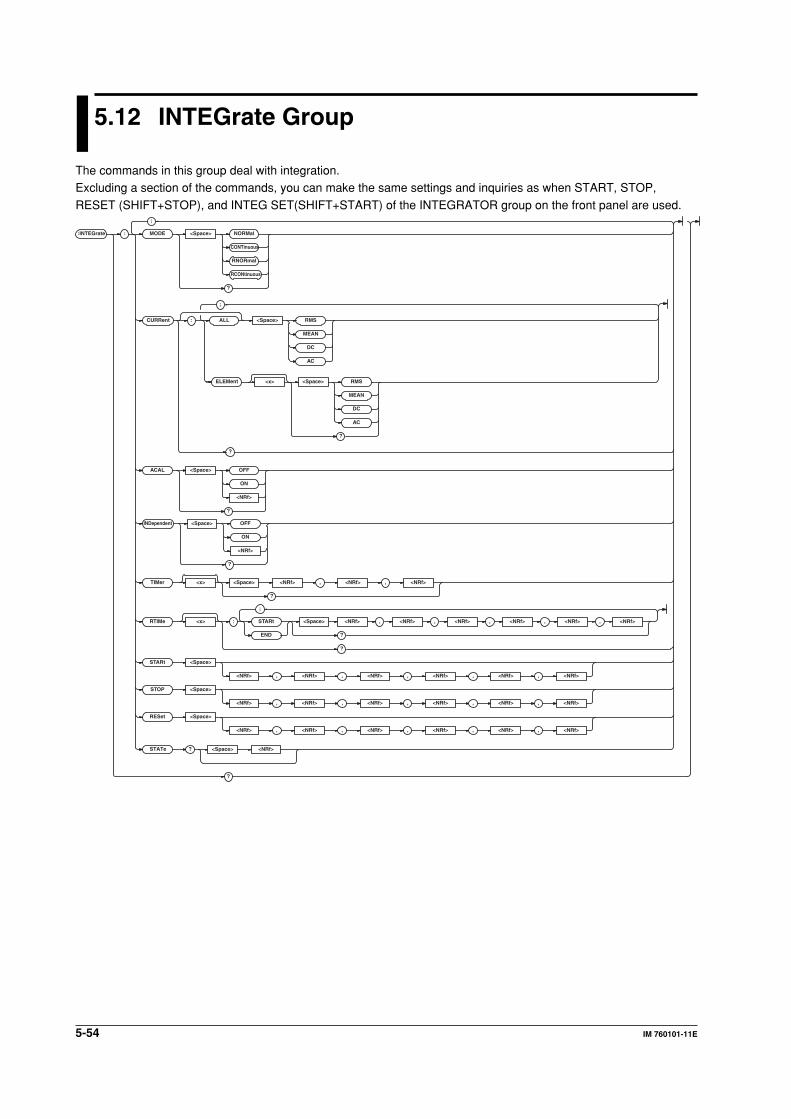
5-54 IM 760101-11E
5.12 INTEGrate Group
The commands in this group deal with integration.Excluding a section of the commands, you can make the same settings and inquiries as when START, STOP,
RESET (SHIFT+STOP), and INTEG SET(SHIFT+START) of the INTEGRATOR group on the front panel are used.
:INTEGrate :
;
MODE <Space> NORMal
CONTinuous
RNORmal
RCONtinuous
?
INDependent <Space> OFF
ON
<NRf>
?
ACAL <Space> OFF
ON
<NRf>
?
TIMer <x> <Space> <NRf>
<Space> <NRf>
, <NRf> , <NRf>
?
RTIMe <x> : STARt <Space> <NRf> , <NRf> , <NRf> , <NRf> , <NRf>
?END
?
STARt <Space>
<NRf> , <NRf> , <NRf> , <NRf> , <NRf> , <NRf>
STOP <Space>
<NRf> , <NRf> , <NRf> , <NRf> , <NRf> , <NRf>
RESet <Space>
<NRf> , <NRf> , <NRf> , <NRf> , <NRf> , <NRf>
?
?
, <NRf>
;
STATe
ALLCURRent <Space> RMS
MEAN
DC
AC
:
?
;
<x>ELEMent <Space> RMS
MEAN
DC
AC
?
5-55IM 760101-11E
Co
mm
and
s
5
:INTEGrate?
Function Queries all settings related to the integration.
Syntax :INTEGrate?
Example • Example during normal integration mode with
individual element integration set to OFF
:INTEGRATE? -> :INTEGRATE:
MODE NORMAL;CURRENT:ELEMENT1 RMS;
ELEMENT2 RMS;ELEMENT3 RMS;
ELEMENT4 RMS;ELEMENT5 RMS;
ELEMENT6 RMS;:INTEGRATE:ACAL 0;
INDEPENDENT 0;TIMER1 1,0,0
• Example during real-time normal integration
mode with individual element integration set
to OFF
:INTEGRATE? -> :INTEGRATE:
MODE RNORMAL;CURRENT:
ELEMENT1 RMS;ELEMENT2 RMS;
ELEMENT3 RMS;ELEMENT4 RMS;
ELEMENT5 RMS;ELEMENT6 RMS;:
INTEGRATE:ACAL 0;INDEPENDENT 0;
TIMER1 1,0,0;RTIME1:
START 2001,1,1,0,0,0;
END 2001,1,1,1,0,0
• Example during normal integration mode with
individual element integration set to ON
:INTEGRATE? -> :INTEGRATE:
MODE NORMAL;CURRENT:ELEMENT1 RMS;
ELEMENT2 RMS;ELEMENT3 RMS;
ELEMENT4 RMS;ELEMENT5 RMS;
ELEMENT6 RMS;:INTEGRATE:ACAL 0;
INDEPENDENT 1;TIMER1 1,0,0;
TIMER2 1,0,0;TIMER3 1,0,0;
TIMER4 1,0,0;TIMER5 1,0,0;
TIMER6 1,0,0
• Example during real-time normal integration
mode with individual element integration set
to ON
:INTEGRATE? -> :INTEGRATE:
MODE RNORMAL;CURRENT:
ELEMENT1 RMS;ELEMENT2 RMS;
ELEMENT3 RMS;ELEMENT4 RMS;
ELEMENT5 RMS;ELEMENT6 RMS;:
INTEGRATE:ACAL 0;INDEPENDENT 1;
TIMER1 1,0,0;TIMER2 1,0,0;
TIMER3 1,0,0;TIMER4 1,0,0;
TIMER5 1,0,0;TIMER6 1,0,0;RTIME1:
START 2001,1,1,0,0,0;
END 2001,1,1,1,0,0;:INTEGRATE:
RTIME2:START 2001,1,1,0,0,0;
END 2001,1,1,1,0,0;:INTEGRATE:
RTIME3:START 2001,1,1,0,0,0;
END 2001,1,1,1,0,0;:INTEGRATE:
RTIME4:START 2001,1,1,0,0,0;
END 2001,1,1,1,0,0;:INTEGRATE:
RTIME5:START 2001,1,1,0,0,0;
END 2001,1,1,1,0,0;:INTEGRATE:
RTIME6:START 2001,1,1,0,0,0;
END 2001,1,1,1,0,0
:INTEGrate:ACAL
Function Turns ON/OFF the auto calibration or queries
the current setting.
Syntax :INTEGrate:ACAL {<Boolean>}
:INTEGrate:ACAL?
Example :INTEGRATE:ACAL OFF
:INTEGRATE:ACAL? -> :INTEGRATE:
ACAL 0
:INTEGrate:CURRent?
Function Queries the current mode of the current
integration of all elements.
Syntax :INTEGrate:CURRent?
Example :INTEGRATE:CURRENT? -> :INTEGRATE:
CURRENT:ELEMENT1 RMS;ELEMENT2 RMS;
ELEMENT3 RMS;ELEMENT4 RMS;
ELEMENT5 RMS;ELEMENT6 RMS
:INTEGrate:CURRent[:ALL]
Function Collectively sets the current mode of the current
integration of all elements.
Syntax :INTEGrate:CURRent[:ALL] {RMS|MEAN|
DC|AC}
Example :INTEGRATE:CURRENT:ALL RMS
:INTEGrate:CURRent:ELEMent<x>
Function Sets the current mode of the current integration
of the element or queries the current setting.
Syntax :INTEGrate:CURRent:ELEMent<x> {RMS|
MEAN|DC|AC}
:INTEGrate:CURRent:ELEMent<x>?
<x> = 1 to 6 (element)
Example :INTEGRATE:CURRENT:ELEMENT1 RMS
:INTEGRATE:CURRENT:ELEMENT1? ->
:INTEGRATE:CURRENT:ELEMENT1 RMS
Description The WT1600 operates according to the current
mode of the current integration of each element
regardless of whether the individual element
integration (:INTEGrate:INDependent) is ON.
:INTEGrate:INDependent
Function Turns ON/OFF the individual element
integration or queries the current setting.
Syntax :INTEGrate:INDependent {<Boolean>}
:INTEGrate:INDependent?
Example :INTEGRATE:INDEPENDENT OFF
:INTEGRATE:INDEPENDENT? ->
:INTEGRATE:INDEPENDENT 0
5.12 INTEGrate Group
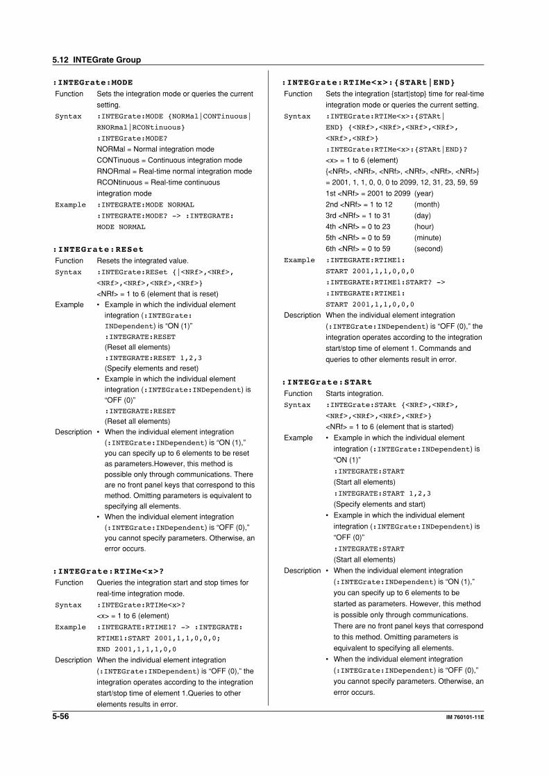
5-56 IM 760101-11E
:INTEGrate:MODE
Function Sets the integration mode or queries the current
setting.
Syntax :INTEGrate:MODE {NORMal|CONTinuous|
RNORmal|RCONtinuous}
:INTEGrate:MODE?
NORMal = Normal integration mode
CONTinuous = Continuous integration mode
RNORmal = Real-time normal integration mode
RCONtinuous = Real-time continuous
integration mode
Example :INTEGRATE:MODE NORMAL
:INTEGRATE:MODE? -> :INTEGRATE:
MODE NORMAL
:INTEGrate:RESet
Function Resets the integrated value.
Syntax :INTEGrate:RESet {|<NRf>,<NRf>,
<NRf>,<NRf>,<NRf>,<NRf>}
<NRf> = 1 to 6 (element that is reset)
Example • Example in which the individual elementintegration (:INTEGrate:INDependent) is “ON (1)”:INTEGRATE:RESET
(Reset all elements):INTEGRATE:RESET 1,2,3
(Specify elements and reset)• Example in which the individual element
integration (:INTEGrate:INDependent) is“OFF (0)”:INTEGRATE:RESET
(Reset all elements)Description • When the individual element integration
(:INTEGrate:INDependent) is “ON (1),”you can specify up to 6 elements to be resetas parameters.However, this method ispossible only through communications. Thereare no front panel keys that correspond to thismethod. Omitting parameters is equivalent tospecifying all elements.
• When the individual element integration(:INTEGrate:INDependent) is “OFF (0),”you cannot specify parameters. Otherwise, anerror occurs.
:INTEGrate:RTIMe<x>?
Function Queries the integration start and stop times for
real-time integration mode.
Syntax :INTEGrate:RTIMe<x>?
<x> = 1 to 6 (element)
Example :INTEGRATE:RTIME1? -> :INTEGRATE:
RTIME1:START 2001,1,1,0,0,0;
END 2001,1,1,1,0,0
Description When the individual element integration
(:INTEGrate:INDependent) is “OFF (0),” the
integration operates according to the integration
start/stop time of element 1.Queries to other
elements results in error.
:INTEGrate:RTIMe<x>:{STARt|END}
Function Sets the integration {start|stop} time for real-time
integration mode or queries the current setting.
Syntax :INTEGrate:RTIMe<x>:{STARt|
END} {<NRf>,<NRf>,<NRf>,<NRf>,
<NRf>,<NRf>}
:INTEGrate:RTIMe<x>:{STARt|END}?
<x> = 1 to 6 (element)
{<NRf>, <NRf>, <NRf>, <NRf>, <NRf>, <NRf>}
= 2001, 1, 1, 0, 0, 0 to 2099, 12, 31, 23, 59, 59
1st <NRf> = 2001 to 2099 (year)
2nd <NRf> = 1 to 12 (month)
3rd <NRf> = 1 to 31 (day)
4th <NRf> = 0 to 23 (hour)
5th <NRf> = 0 to 59 (minute)
6th <NRf> = 0 to 59 (second)
Example :INTEGRATE:RTIME1:
START 2001,1,1,0,0,0
:INTEGRATE:RTIME1:START? ->
:INTEGRATE:RTIME1:
START 2001,1,1,0,0,0
Description When the individual element integration
(:INTEGrate:INDependent) is “OFF (0),” the
integration operates according to the integration
start/stop time of element 1. Commands and
queries to other elements result in error.
:INTEGrate:STARt
Function Starts integration.
Syntax :INTEGrate:STARt {<NRf>,<NRf>,
<NRf>,<NRf>,<NRf>,<NRf>}
<NRf> = 1 to 6 (element that is started)
Example • Example in which the individual element
integration (:INTEGrate:INDependent) is
“ON (1)”
:INTEGRATE:START
(Start all elements)
:INTEGRATE:START 1,2,3
(Specify elements and start)
• Example in which the individual element
integration (:INTEGrate:INDependent) is
“OFF (0)”
:INTEGRATE:START
(Start all elements)
Description • When the individual element integration
(:INTEGrate:INDependent) is “ON (1),”
you can specify up to 6 elements to be
started as parameters. However, this method
is possible only through communications.
There are no front panel keys that correspond
to this method. Omitting parameters is
equivalent to specifying all elements.
• When the individual element integration
(:INTEGrate:INDependent) is “OFF (0),”
you cannot specify parameters. Otherwise, an
error occurs.
5.12 INTEGrate Group
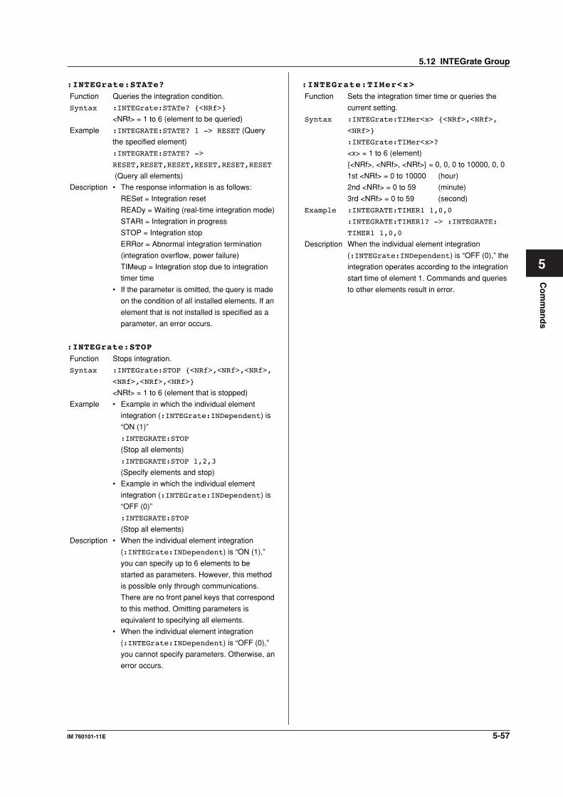
5-57IM 760101-11E
Co
mm
and
s
5
:INTEGrate:STATe?
Function Queries the integration condition.
Syntax :INTEGrate:STATe? {<NRf>}
<NRf> = 1 to 6 (element to be queried)
Example :INTEGRATE:STATE? 1 -> RESET (Query
the specified element)
:INTEGRATE:STATE? ->
RESET,RESET,RESET,RESET,RESET,RESET
(Query all elements)
Description • The response information is as follows:
RESet = Integration reset
READy = Waiting (real-time integration mode)
STARt = Integration in progress
STOP = Integration stop
ERRor = Abnormal integration termination
(integration overflow, power failure)
TIMeup = Integration stop due to integration
timer time
• If the parameter is omitted, the query is made
on the condition of all installed elements. If an
element that is not installed is specified as a
parameter, an error occurs.
:INTEGrate:STOP
Function Stops integration.
Syntax :INTEGrate:STOP {<NRf>,<NRf>,<NRf>,
<NRf>,<NRf>,<NRf>}
<NRf> = 1 to 6 (element that is stopped)
Example • Example in which the individual element
integration (:INTEGrate:INDependent) is
“ON (1)”
:INTEGRATE:STOP
(Stop all elements)
:INTEGRATE:STOP 1,2,3
(Specify elements and stop)
• Example in which the individual element
integration (:INTEGrate:INDependent) is
“OFF (0)”
:INTEGRATE:STOP
(Stop all elements)
Description • When the individual element integration
(:INTEGrate:INDependent) is “ON (1),”
you can specify up to 6 elements to be
started as parameters. However, this method
is possible only through communications.
There are no front panel keys that correspond
to this method. Omitting parameters is
equivalent to specifying all elements.
• When the individual element integration
(:INTEGrate:INDependent) is “OFF (0),”
you cannot specify parameters. Otherwise, an
error occurs.
:INTEGrate:TIMer<x>
Function Sets the integration timer time or queries the
current setting.
Syntax :INTEGrate:TIMer<x> {<NRf>,<NRf>,
<NRf>}
:INTEGrate:TIMer<x>?
<x> = 1 to 6 (element)
{<NRf>, <NRf>, <NRf>} = 0, 0, 0 to 10000, 0, 0
1st <NRf> = 0 to 10000 (hour)
2nd <NRf> = 0 to 59 (minute)
3rd <NRf> = 0 to 59 (second)
Example :INTEGRATE:TIMER1 1,0,0
:INTEGRATE:TIMER1? -> :INTEGRATE:
TIMER1 1,0,0
Description When the individual element integration
(:INTEGrate:INDependent) is “OFF (0),” the
integration operates according to the integration
start time of element 1. Commands and queries
to other elements result in error.
5.12 INTEGrate Group
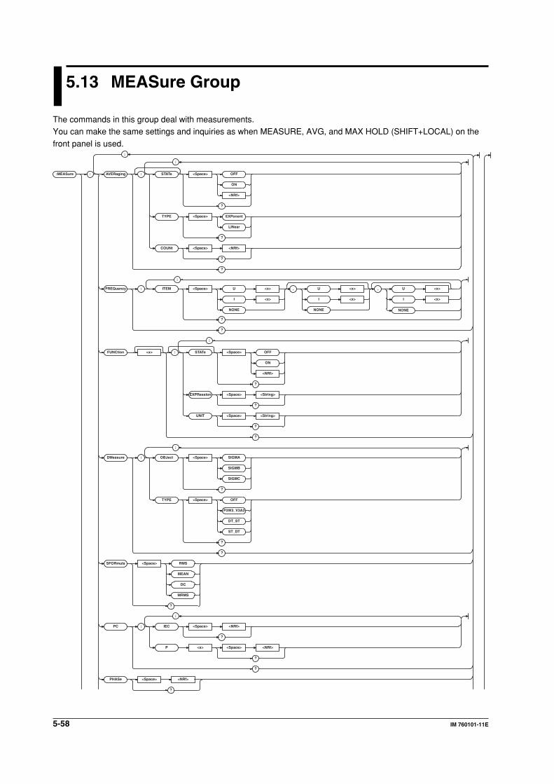
5-58 IM 760101-11E
5.13 MEASure Group
The commands in this group deal with measurements.You can make the same settings and inquiries as when MEASURE, AVG, and MAX HOLD (SHIFT+LOCAL) on the
front panel is used.
:MEASure : AVERaging : STAT e <Space> OFF
ON
<NRf>
?
TYPE <Space> EXPonent
LINear
?
COUNt <Space> <NRf>
?
?
FREQuency : ITEM <Space> U <x> , U <x> , U <x>
I <x>
NONE
I <x>
NONE
I <x>
NONE
?
?
FUNCtion <x> : STAT e <Space> OFF
ON
<NRf>
?
EXPRession <Space> <String>
?
UNIT <Space> <String>
?
?
DMeasure : OBJect <Space> SIGMA
SIGMB
SIGMC
?
TYPE <Space> OFF
P3W3_V3A3
DT_ST
ST_DT
?
?
SFORmula <Space> RMS
MEAN
DC
MRMS
?
PC : IEC <Space> <NRf>
?
P <x> <Space> <NRf>
?
?
PHASe <Space> <NRf>
?
;
;
;
;
;
;
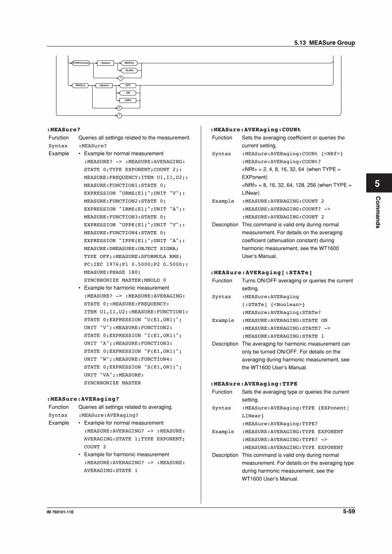
5-59IM 760101-11E
Co
mm
and
s
5
SYNChroniz e <Space> MASTer
SLAVe
?
MHOLd <Space> OFF
ON
<NRf>
?
?
:MEASure:AVERaging:COUNt
Function Sets the averaging coefficient or queries the
current setting.
Syntax :MEASure:AVERaging:COUNt {<NRf>}
:MEASure:AVERaging:COUNt?
<NRf> = 2, 4, 8, 16, 32, 64 (when TYPE =
EXPonent)
<NRf> = 8, 16, 32, 64, 128, 256 (when TYPE =
LINear)
Example :MEASURE:AVERAGING:COUNT 2
:MEASURE:AVERAGING:COUNT? ->
:MEASURE:AVERAGING:COUNT 2
Description This command is valid only during normal
measurement. For details on the averaging
coefficient (attenuation constant) during
harmonic measurement, see the WT1600
User’s Manual.
:MEASure:AVERaging[:STATe]
Function Turns ON/OFF averaging or queries the current
setting.
Syntax :MEASure:AVERaging
[:STATe] {<Boolean>}
:MEASure:AVERaging:STATe?
Example :MEASURE:AVERAGING:STATE ON
:MEASURE:AVERAGING:STATE? ->
:MEASURE:AVERAGING:STATE 1
Description The averaging for harmonic measurement can
only be turned ON/OFF. For details on the
averaging during harmonic measurement, see
the WT1600 User’s Manual.
:MEASure:AVERaging:TYPE
Function Sets the averaging type or queries the current
setting.
Syntax :MEASure:AVERaging:TYPE {EXPonent|
LINear}
:MEASure:AVERaging:TYPE?
Example :MEASURE:AVERAGING:TYPE EXPONENT
:MEASURE:AVERAGING:TYPE? ->
:MEASURE:AVERAGING:TYPE EXPONENT
Description This command is valid only during normal
measurement. For details on the averaging type
during harmonic measurement, see the
WT1600 User’s Manual.
:MEASure?
Function Queries all settings related to the measurement.
Syntax :MEASure?
Example • Example for normal measurement
:MEASURE? -> :MEASURE:AVERAGING:
STATE 0;TYPE EXPONENT;COUNT 2;:
MEASURE:FREQUENCY:ITEM U1,I1,U2;:
MEASURE:FUNCTION1:STATE 0;
EXPRESSION "URMS(E1)";UNIT "V";:
MEASURE:FUNCTION2:STATE 0;
EXPRESSION "IRMS(E1)";UNIT "A";:
MEASURE:FUNCTION3:STATE 0;
EXPRESSION "UPPK(E1)";UNIT "V";:
MEASURE:FUNCTION4:STATE 0;
EXPRESSION "IPPK(E1)";UNIT "A";:
MEASURE:DMEASURE:OBJECT SIGMA;
TYPE OFF;:MEASURE:SFORMULA RMS;
PC:IEC 1976;P1 0.5000;P2 0.5000;:
MEASURE:PHASE 180;
SYNCHRONIZE MASTER;MHOLD 0
• Example for harmonic measurement
:MEASURE? -> :MEASURE:AVERAGING:
STATE 0;:MEASURE:FREQUENCY:
ITEM U1,I1,U2;:MEASURE:FUNCTION1:
STATE 0;EXPRESSION "U(E1,OR1)";
UNIT "V";:MEASURE:FUNCTION2:
STATE 0;EXPRESSION "I(E1,OR1)";
UNIT "A";:MEASURE:FUNCTION3:
STATE 0;EXPRESSION "P(E1,OR1)";
UNIT "W";:MEASURE:FUNCTION4:
STATE 0;EXPRESSION "S(E1,OR1)";
UNIT "VA";:MEASURE:
SYNCHRONIZE MASTER
:MEASure:AVERaging?
Function Queries all settings related to averaging.
Syntax :MEASure:AVERaging?
Example • Example for normal measurement
:MEASURE:AVERAGING? -> :MEASURE:
AVERAGING:STATE 1;TYPE EXPONENT;
COUNT 2
• Example for harmonic measurement
:MEASURE:AVERAGING? -> :MEASURE:
AVERAGING:STATE 1
5.13 MEASure Group
5-60 IM 760101-11E
:MEASure:DMeasure?
Function Queries all settings related to the delta
computation.
Syntax :MEASure:DMeasure?
Example :MEASURE:DMEASURE? -> :MEASURE:
DMEASURE:OBJECT SIGMA;TYPE OFF
:MEASure:DMeasure:OBJect
Function Sets the delta computation target or queries the
current setting.
Syntax :MEASure:DMeasure:OBJect {SIGMA|
SIGMB|SIGMC}
:MEASure:DMeasure:OBJect?
SIGMA = ΣA
SIGMB = ΣB (selectable on models with 2 or
more elements)
SIGMC = ΣC (selectable on models with 3 or
more elements)
Example :MEASURE:DMEASURE:OBJECT SIGMA
:MEASURE:DMEASURE:OBJECT? ->
:MEASURE:DMEASURE:OBJECT SIGMA
Description This command is valid only during normal
measurement.
:MEASure:DMeasure:TYPE
Function Sets the delta computation mode or queries the
current setting.
Syntax :MEASure:DMeasure:TYPE {OFF|
P3W3_V3A3|DT_ST|ST_DT}
:MEASure:DMeasure:TYPE?
Example :MEASURE:DMEASURE:TYPE OFF
:MEASURE:DMEASURE:TYPE? ->
:MEASURE:DMEASURE:TYPE OFF
Description • This command is valid only during normal
measurement.
• The selections are as follows:
OFF = Not perform delta computation
P3W3_V3A3 = 3P3W -> 3V3A conversion
DT_ST = Delta -> Star conversion
ST_DT = Star -> Delta conversion
• Some of the selections may not be possible
depending on the wiring system of the
specified delta computation target
(:MEASure:DMeasure:OBJect).
:MEASure:FREQuency?
Function Queries all settings related to frequency
measurement.
Syntax :MEASure:FREQuency?
Example :MEASURE:FREQUENCY? -> :MEASURE:
FREQUENCY:ITEM U1,I1,U2
:MEASure:FREQuency:ITEM
Function Sets the frequency measurement item or
queries the current setting.
Syntax :MEASure:FREQuency:ITEM {(U<x>|
I<x>|NONE)[,(U<x>|I<x>|NONE)]
[,(U<x>|I<x>|NONE)]}
:MEASure:FREQuency:ITEM?
<x> = 1 to 6 (element)
Example :MEASURE:FREQUENCY:ITEM U1,I1,U2
:MEASURE:FREQUENCY:ITEM? ->
:MEASURE:FREQUENCY:ITEM U1,I1,U2
Description • You can specify up to three frequency
measurement items.
• If you are not specifying the frequency
measurement item, select “NONE.” The 2nd
and 3rd parameters can be omitted.
:MEASure:FUNCtion<x>?
Function Queries all settings related to user-defined
functions.
Syntax :MEASure:FUNCtion<x>?
<x> = 1 to 4
Example :MEASURE:FUNCTION1? -> :MEASURE:
FUNCTION1:STATE 1;
EXPRESSION "URMS(E1)";UNIT "V"
:MEASure:FUNCtion<x>:EXPRession
Function Sets the equation of the user-defined function or
queries the current setting.
Syntax :MEASure:FUNCtion<x>:EXPRession
{<String>}
:MEASure:FUNCtion<x>:EXPRession?
<x> = 1 to 4
<string> = 50 characters or less
Example :MEASURE:FUNCTION1:
EXPRESSION "URMS(E1)"
:MEASURE:FUNCTION1:EXPRESSION? ->
:MEASURE:FUNCTION1:
EXPRESSION "URMS(E1)"
Description Characters and symbols other than the ones
displayed on the keyboard on the screen cannot
be used.
:MEASure:FUNCtion<x>[:STATe]
Function Enables (ON) or Disables (OFF) the user-
defined function or queries the current setting.
Syntax :MEASure:FUNCtion<x>
[:STATe] {<Boolean>}
:MEASure:FUNCtion<x>:STATe?
<x> = 1 to 4
Example :MEASURE:FUNCTION1:STATE ON
:MEASURE:FUNCTION1:STATE? ->
:MEASURE:FUNCTION1:STATE 1
5.13 MEASure Group
5-61IM 760101-11E
Co
mm
and
s
5
:MEASure:FUNCtion<x>:UNIT
Function Sets the unit to be added to the computation
result of the user-defined function or queries the
current setting.
Syntax :MEASure:FUNCtion<x>:
UNIT {<String>}
:MEASure:FUNCtion<x>:UNIT?
<x> = 1 to 4
<string> = 8 characters or less
Example :MEASURE:FUNCTION1:UNIT "V"
:MEASURE:FUNCTION1:UNIT? ->
:MEASURE:FUNCTION1:UNIT "V"
Description • Only the characters and symbols displayed
on the keyboard on the screen can be used.
• This command does not affect the
computation result.
:MEASure:MHOLd
Function Turns ON/OFF the MAX HOLD function or
queries the current setting.
Syntax :MEASure:MHOLd {<Boolean>}
:MEASure:MHOLd?
Example :MEASURE:MHOLD ON
:MEASURE:MHOLD? -> :MEASURE:MHOLD 1
Description This command is valid only during normal
measurement.
:MEASure:PC?
Function Queries all settings related to the calculation of
Pc (Corrected Power).
Syntax :MEASure:PC?
Example :MEASURE:PC? -> :MEASURE:PC:
IEC 1976;P1 0.5000;P2 0.5000
:MEASure:PC:IEC
Function Sets the equation used to calculate Pc
(Corrected Power) or queries the current
setting.
Syntax :MEASure:PC:IEC {<NRf>}
:MEASure:PC:IEC?
<NRf> = 1976, 1993
Example :MEASURE:PC:IEC 1976
:MEASURE:PC:IEC? -> :MEASURE:PC:
IEC 1976
Description • This command is valid only during normal
measurement.
• Specify the year when the equation used to
calculate the Pc was issued by IEC76-1.
:MEASure:PC:P<x>
Function Sets the parameter used to calculate Pc
(Corrected Power) or queries the current
setting.
Syntax :MEASure:PC:P<x> {<NRf>}
:MEASure:PC:P<x>?
<x> = 1, 2
<NRf> = 0.0000 to 9.9999
Example :MEASURE:PC:P1 0.5
:MEASURE:PC:P1? -> :MEASURE:PC:
P1 0.5000
Description • This command is valid only during normal
measurement.
• This parameter is used when the
“:MEASure:PC:IEC” setting is set to
“1976(IEC76-1(1976)).”
:MEASure:PHASe
Function Sets the display format of the phase difference
or queries the current setting.
Syntax :MEASure:PHASe {<NRf>}
:MEASure:PHASe?
<NRf> = 180, 360
Example :MEASURE:PHASE 180
:MEASURE:PHASE? -> :MEASURE:
PHASE 180
Description • This command is valid only during normal
measurement.
• Displays the phase using ±0 to 180° (Lead/
Lag) for “180” and 0 to 360° for “360.”
:MEASure:SFORmula
Function Sets the equation used to calculate S (reactive
power) or queries the current setting.
Syntax :MEASure:SFORmula {RMS|MEAN|DC|
MRMS}
:MEASure:SFORmula?
Example :MEASURE:SFORMULA RMS
:MEASURE:SFORMULA? -> :MEASURE:
SFORMULA RMS
Description • This command is valid only during normal
measurement.
• The correspondence between the selections
and equations is as follows.
RMS: S = Urms * Irms
MEAN: S = Umean * Imean
DC: S = Udc * Idc
MRMS: S = Umean * Irms
:MEASure:SYNChronize
Function Sets the synchronized measurement mode or
queries the current setting.
Syntax :MEASure:SYNChronize {MASTer|SLAVe}
:MEASure:SYNChronize?
Example :MEASURE:SYNCHRONIZE MASTER
:MEASURE:SYNCHRONIZE? -> :MEASURE:
SYNCHRONIZE MASTER
5.13 MEASure Group
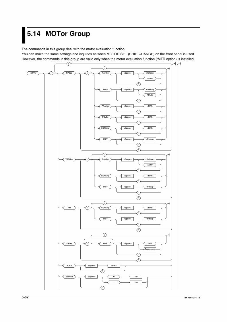
5-62 IM 760101-11E
5.14 MOTor Group
The commands in this group deal with the motor evaluation function.You can make the same settings and inquiries as when MOTOR SET (SHIFT+RANGE) on the front panel is used.
However, the commands in this group are valid only when the motor evaluation function (/MTR option) is installed.
:MOTor :
;
SPEed : RANGe <Space> <Voltage>
AUTO
?
TYPE <Space> ANALog
PULSe
?
PULSe <Space> <NRf>
?
SCALing <Space> <NRf>
?
UNIT <Space> <String>
?
?
TORQue : RANGe <Space> <Voltage>
AUTO
?
SCALing <Space> <NRf>
?
UNIT <Space> <String>
?
?
PM : SCALing <Space> <NRf>
?
UNIT <Space> <String>
?
?
FILTer : LINE <Space> OFF
<Frequency>
?
?
POLE <Space> <NRf>
?
SSPeed <Space> U <x>
I <x>
?
;
;
;
;
PRANge <Space> <NRf>
?
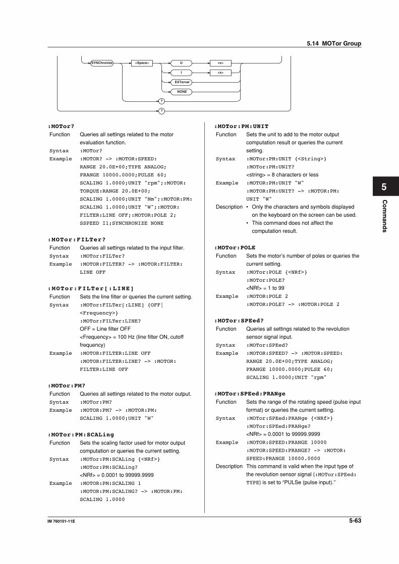
5-63IM 760101-11E
Co
mm
and
s
5
SYNChroniz e <Space> U <x>
I <x>
?
?
EXTernal
NONE
:MOTor?
Function Queries all settings related to the motor
evaluation function.
Syntax :MOTor?
Example :MOTOR? -> :MOTOR:SPEED:
RANGE 20.0E+00;TYPE ANALOG;
PRANGE 10000.0000;PULSE 60;
SCALING 1.0000;UNIT "rpm";:MOTOR:
TORQUE:RANGE 20.0E+00;
SCALING 1.0000;UNIT "Nm";:MOTOR:PM:
SCALING 1.0000;UNIT "W";:MOTOR:
FILTER:LINE OFF;:MOTOR:POLE 2;
SSPEED I1;SYNCHRONIZE NONE
:MOTor:FILTer?
Function Queries all settings related to the input filter.
Syntax :MOTor:FILTer?
Example :MOTOR:FILTER? -> :MOTOR:FILTER:
LINE OFF
:MOTor:FILTer[:LINE]
Function Sets the line filter or queries the current setting.
Syntax :MOTor:FILTer[:LINE] {OFF|
<Frequency>}
:MOTor:FILTer:LINE?
OFF = Line filter OFF
<Frequency> = 100 Hz (line filter ON, cutoff
frequency)
Example :MOTOR:FILTER:LINE OFF
:MOTOR:FILTER:LINE? -> :MOTOR:
FILTER:LINE OFF
:MOTor:PM?
Function Queries all settings related to the motor output.
Syntax :MOTor:PM?
Example :MOTOR:PM? -> :MOTOR:PM:
SCALING 1.0000;UNIT "W"
:MOTor:PM:SCALing
Function Sets the scaling factor used for motor output
computation or queries the current setting.
Syntax :MOTor:PM:SCALing {<NRf>}
:MOTor:PM:SCALing?
<NRf> = 0.0001 to 99999.9999
Example :MOTOR:PM:SCALING 1
:MOTOR:PM:SCALING? -> :MOTOR:PM:
SCALING 1.0000
:MOTor:PM:UNIT
Function Sets the unit to add to the motor output
computation result or queries the current
setting.
Syntax :MOTor:PM:UNIT {<String>}
:MOTor:PM:UNIT?
<string> = 8 characters or less
Example :MOTOR:PM:UNIT "W"
:MOTOR:PM:UNIT? -> :MOTOR:PM:
UNIT "W"
Description • Only the characters and symbols displayed
on the keyboard on the screen can be used.
• This command does not affect the
computation result.
:MOTor:POLE
Function Sets the motor’s number of poles or queries the
current setting.
Syntax :MOTor:POLE {<NRf>}
:MOTor:POLE?
<NRf> = 1 to 99
Example :MOTOR:POLE 2
:MOTOR:POLE? -> :MOTOR:POLE 2
:MOTor:SPEed?
Function Queries all settings related to the revolution
sensor signal input.
Syntax :MOTor:SPEed?
Example :MOTOR:SPEED? -> :MOTOR:SPEED:
RANGE 20.0E+00;TYPE ANALOG;
PRANGE 10000.0000;PULSE 60;
SCALING 1.0000;UNIT "rpm"
:MOTor:SPEed:PRANge
Function Sets the range of the rotating speed (pulse input
format) or queries the current setting.
Syntax :MOTor:SPEed:PRANge {<NRf>}
:MOTor:SPEed:PRANge?
<NRf> = 0.0001 to 99999.9999
Example :MOTOR:SPEED:PRANGE 10000
:MOTOR:SPEED:PRANGE? -> :MOTOR:
SPEED:PRANGE 10000.0000
Description This command is valid when the input type of
the revolution sensor signal (:MOTor:SPEed:
TYPE) is set to “PULSe (pulse input).”
5.14 MOTor Group
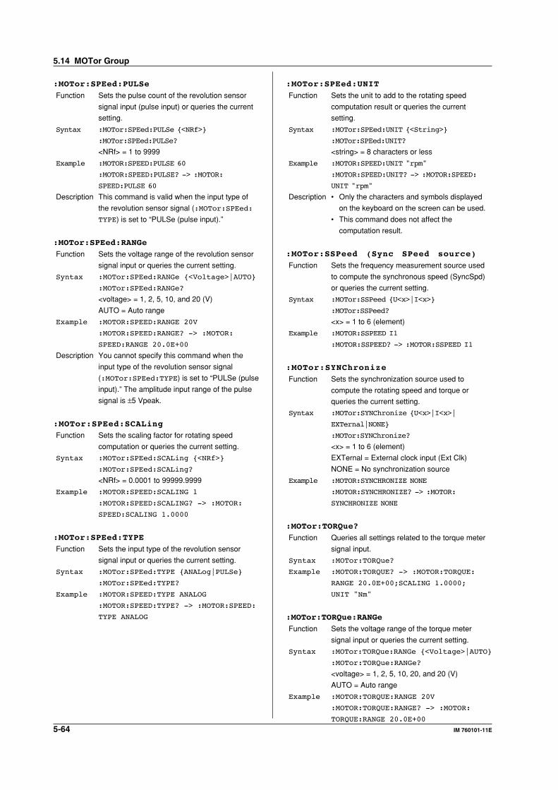
5-64 IM 760101-11E
:MOTor:SPEed:PULSe
Function Sets the pulse count of the revolution sensor
signal input (pulse input) or queries the current
setting.
Syntax :MOTor:SPEed:PULSe {<NRf>}
:MOTor:SPEed:PULSe?
<NRf> = 1 to 9999
Example :MOTOR:SPEED:PULSE 60
:MOTOR:SPEED:PULSE? -> :MOTOR:
SPEED:PULSE 60
Description This command is valid when the input type of
the revolution sensor signal (:MOTor:SPEed:
TYPE) is set to “PULSe (pulse input).”
:MOTor:SPEed:RANGe
Function Sets the voltage range of the revolution sensor
signal input or queries the current setting.
Syntax :MOTor:SPEed:RANGe {<Voltage>|AUTO}
:MOTor:SPEed:RANGe?
<voltage> = 1, 2, 5, 10, and 20 (V)
AUTO = Auto range
Example :MOTOR:SPEED:RANGE 20V
:MOTOR:SPEED:RANGE? -> :MOTOR:
SPEED:RANGE 20.0E+00
Description You cannot specify this command when the
input type of the revolution sensor signal
(:MOTor:SPEed:TYPE) is set to “PULSe (pulse
input).” The amplitude input range of the pulse
signal is ±5 Vpeak.
:MOTor:SPEed:SCALing
Function Sets the scaling factor for rotating speed
computation or queries the current setting.
Syntax :MOTor:SPEed:SCALing {<NRf>}
:MOTor:SPEed:SCALing?
<NRf> = 0.0001 to 99999.9999
Example :MOTOR:SPEED:SCALING 1
:MOTOR:SPEED:SCALING? -> :MOTOR:
SPEED:SCALING 1.0000
:MOTor:SPEed:TYPE
Function Sets the input type of the revolution sensor
signal input or queries the current setting.
Syntax :MOTor:SPEed:TYPE {ANALog|PULSe}
:MOTor:SPEed:TYPE?
Example :MOTOR:SPEED:TYPE ANALOG
:MOTOR:SPEED:TYPE? -> :MOTOR:SPEED:
TYPE ANALOG
:MOTor:SPEed:UNIT
Function Sets the unit to add to the rotating speed
computation result or queries the current
setting.
Syntax :MOTor:SPEed:UNIT {<String>}
:MOTor:SPEed:UNIT?
<string> = 8 characters or less
Example :MOTOR:SPEED:UNIT "rpm"
:MOTOR:SPEED:UNIT? -> :MOTOR:SPEED:
UNIT "rpm"
Description • Only the characters and symbols displayed
on the keyboard on the screen can be used.
• This command does not affect the
computation result.
:MOTor:SSPeed (Sync SPeed source)
Function Sets the frequency measurement source used
to compute the synchronous speed (SyncSpd)
or queries the current setting.
Syntax :MOTor:SSPeed {U<x>|I<x>}
:MOTor:SSPeed?
<x> = 1 to 6 (element)
Example :MOTOR:SSPEED I1
:MOTOR:SSPEED? -> :MOTOR:SSPEED I1
:MOTor:SYNChronize
Function Sets the synchronization source used to
compute the rotating speed and torque or
queries the current setting.
Syntax :MOTor:SYNChronize {U<x>|I<x>|
EXTernal|NONE}
:MOTor:SYNChronize?
<x> = 1 to 6 (element)
EXTernal = External clock input (Ext Clk)
NONE = No synchronization source
Example :MOTOR:SYNCHRONIZE NONE
:MOTOR:SYNCHRONIZE? -> :MOTOR:
SYNCHRONIZE NONE
:MOTor:TORQue?
Function Queries all settings related to the torque meter
signal input.
Syntax :MOTor:TORQue?
Example :MOTOR:TORQUE? -> :MOTOR:TORQUE:
RANGE 20.0E+00;SCALING 1.0000;
UNIT "Nm"
:MOTor:TORQue:RANGe
Function Sets the voltage range of the torque meter
signal input or queries the current setting.
Syntax :MOTor:TORQue:RANGe {<Voltage>|AUTO}
:MOTor:TORQue:RANGe?
<voltage> = 1, 2, 5, 10, 20, and 20 (V)
AUTO = Auto range
Example :MOTOR:TORQUE:RANGE 20V
:MOTOR:TORQUE:RANGE? -> :MOTOR:
TORQUE:RANGE 20.0E+00
5.14 MOTor Group
5-65IM 760101-11E
Co
mm
and
s
5
:MOTor:TORQue:SCALing
Function Sets the scaling factor for torque computation or
queries the current setting.
Syntax :MOTor:TORQue:SCALing {<NRf>}
:MOTor:TORQue:SCALing?
<NRf> = 0.0001 to 99999.9999
Example :MOTOR:TORQUE:SCALING 1
:MOTOR:TORQUE:SCALING? -> :MOTOR:
TORQUE:SCALING 1.0000
:MOTor:TORQue:UNIT
Function Sets the unit to add to the torque computation
result or queries the current setting.
Syntax :MOTor:TORQue:UNIT {<String>}
:MOTor:TORQue:UNIT?
<string> = 8 characters or less
Example :MOTOR:TORQUE:UNIT "Nm"
:MOTOR:TORQUE:UNIT? -> :MOTOR:
TORQUE:UNIT "Nm"
Description • Only the characters and symbols displayed
on the keyboard on the screen can be used.
• This command does not affect the
computation result.
5.14 MOTor Group
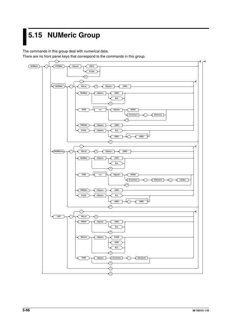
5-66 IM 760101-11E
5.15 NUMeric Group
The commands in this group deal with numerical data.There are no front panel keys that correspond to the commands in this group.
:NUMeric :
;
FORMat <Space> ASCii
FLOat
?
NORMal : VALue ? <Space>
NUMber <Space> <NRf>
ALL
?
ITEM <x> <Space> NONE
<Function> , <Element>
?
PRESet <Space> <NRf>
CLEar <Space> ALL
<NRf> , <NRf>
?
HARMonics : VALue ? <Space>
NUMber <Space> <NRf>
ALL
?
ITEM <x> <Space> NONE
<Function> , <Element> , <Order>
?
PRESet <Space> <NRf>
CLEar <Space> ALL
<NRf> , <NRf>
?
LIST : VALue ?
ORDer <Space> <NRf>
ALL
?
SELect <Space> EVEN
ODD
ALL
?
ITEM <Space> <Function> , <Element>
?
?
?
;
;
;
<NRf>
<NRf>
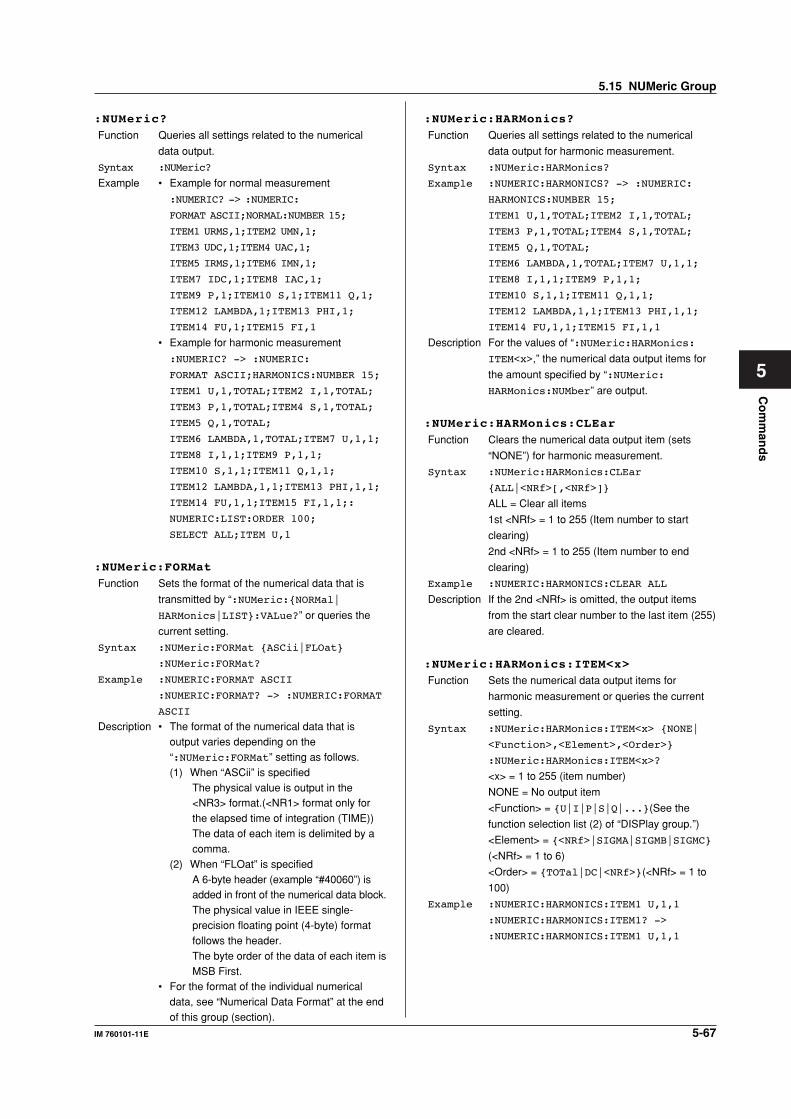
5-67IM 760101-11E
Co
mm
and
s
5
:NUMeric?
Function Queries all settings related to the numerical
data output.
Syntax :NUMeric?
Example • Example for normal measurement
:NUMERIC? -> :NUMERIC:
FORMAT ASCII;NORMAL:NUMBER 15;
ITEM1 URMS,1;ITEM2 UMN,1;
ITEM3 UDC,1;ITEM4 UAC,1;
ITEM5 IRMS,1;ITEM6 IMN,1;
ITEM7 IDC,1;ITEM8 IAC,1;
ITEM9 P,1;ITEM10 S,1;ITEM11 Q,1;
ITEM12 LAMBDA,1;ITEM13 PHI,1;
ITEM14 FU,1;ITEM15 FI,1
• Example for harmonic measurement
:NUMERIC? -> :NUMERIC:
FORMAT ASCII;HARMONICS:NUMBER 15;
ITEM1 U,1,TOTAL;ITEM2 I,1,TOTAL;
ITEM3 P,1,TOTAL;ITEM4 S,1,TOTAL;
ITEM5 Q,1,TOTAL;
ITEM6 LAMBDA,1,TOTAL;ITEM7 U,1,1;
ITEM8 I,1,1;ITEM9 P,1,1;
ITEM10 S,1,1;ITEM11 Q,1,1;
ITEM12 LAMBDA,1,1;ITEM13 PHI,1,1;
ITEM14 FU,1,1;ITEM15 FI,1,1;:
NUMERIC:LIST:ORDER 100;
SELECT ALL;ITEM U,1
:NUMeric:FORMat
Function Sets the format of the numerical data that is
transmitted by “:NUMeric:{NORMal|
HARMonics|LIST}:VALue?” or queries the
current setting.
Syntax :NUMeric:FORMat {ASCii|FLOat}
:NUMeric:FORMat?
Example :NUMERIC:FORMAT ASCII
:NUMERIC:FORMAT? -> :NUMERIC:FORMAT
ASCII
Description • The format of the numerical data that isoutput varies depending on the“:NUMeric:FORMat” setting as follows.(1) When “ASCii” is specified
The physical value is output in the<NR3> format.(<NR1> format only forthe elapsed time of integration (TIME))The data of each item is delimited by acomma.
(2) When “FLOat” is specifiedA 6-byte header (example “#40060”) isadded in front of the numerical data block.The physical value in IEEE single-precision floating point (4-byte) formatfollows the header.The byte order of the data of each item isMSB First.
• For the format of the individual numericaldata, see “Numerical Data Format” at the endof this group (section).
:NUMeric:HARMonics?
Function Queries all settings related to the numerical
data output for harmonic measurement.
Syntax :NUMeric:HARMonics?
Example :NUMERIC:HARMONICS? -> :NUMERIC:
HARMONICS:NUMBER 15;
ITEM1 U,1,TOTAL;ITEM2 I,1,TOTAL;
ITEM3 P,1,TOTAL;ITEM4 S,1,TOTAL;
ITEM5 Q,1,TOTAL;
ITEM6 LAMBDA,1,TOTAL;ITEM7 U,1,1;
ITEM8 I,1,1;ITEM9 P,1,1;
ITEM10 S,1,1;ITEM11 Q,1,1;
ITEM12 LAMBDA,1,1;ITEM13 PHI,1,1;
ITEM14 FU,1,1;ITEM15 FI,1,1
Description For the values of “:NUMeric:HARMonics:
ITEM<x>,” the numerical data output items for
the amount specified by “:NUMeric:
HARMonics:NUMber” are output.
:NUMeric:HARMonics:CLEar
Function Clears the numerical data output item (sets
“NONE”) for harmonic measurement.
Syntax :NUMeric:HARMonics:CLEar
{ALL|<NRf>[,<NRf>]}
ALL = Clear all items
1st <NRf> = 1 to 255 (Item number to start
clearing)
2nd <NRf> = 1 to 255 (Item number to end
clearing)
Example :NUMERIC:HARMONICS:CLEAR ALL
Description If the 2nd <NRf> is omitted, the output items
from the start clear number to the last item (255)
are cleared.
:NUMeric:HARMonics:ITEM<x>
Function Sets the numerical data output items for
harmonic measurement or queries the current
setting.
Syntax :NUMeric:HARMonics:ITEM<x> {NONE|
<Function>,<Element>,<Order>}
:NUMeric:HARMonics:ITEM<x>?
<x> = 1 to 255 (item number)
NONE = No output item
<Function> = {U|I|P|S|Q|...}(See the
function selection list (2) of “DISPlay group.”)
<Element> = {<NRf>|SIGMA|SIGMB|SIGMC}
(<NRf> = 1 to 6)
<Order> = {TOTal|DC|<NRf>}(<NRf> = 1 to
100)
Example :NUMERIC:HARMONICS:ITEM1 U,1,1
:NUMERIC:HARMONICS:ITEM1? ->
:NUMERIC:HARMONICS:ITEM1 U,1,1
5.15 NUMeric Group
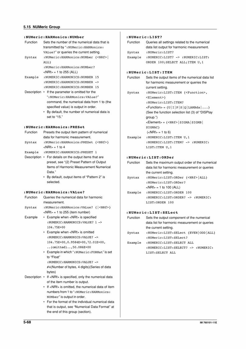
5-68 IM 760101-11E
:NUMeric:HARMonics:NUMber
Function Sets the number of the numerical data that is
transmitted by “:NUMeric:HARMonics:
VALue?” or queries the current setting.
Syntax :NUMeric:HARMonics:NUMber {<NRf>|
ALL}
:NUMeric:HARMonics:NUMber?
<NRf> = 1 to 255 (ALL)
Example :NUMERIC:HARMONICS:NUMBER 15
:NUMERIC:HARMONICS:NUMBER ->
:NUMERIC:HARMONICS:NUMBER 15
Description • If the parameter is omitted for the
“:NUMeric:HARMonics:VALue?”
command, the numerical data from 1 to (the
specified value) is output in order.
• By default, the number of numerical data is
set to “15.”
:NUMeric:HARMonics:PRESet
Function Presets the output item pattern of numerical
data for harmonic measurement.
Syntax :NUMeric:HARMonics:PRESet {<NRf>}
<NRf> = 1 to 4
Example :NUMERIC:HARMONICS:PRESET 1
Description • For details on the output items that are
preset, see “(2) Preset Pattern of Output
Items of Harmonic Measurement Numerical
Data.”
• By default, output items of “Pattern 2” is
selected.
:NUMeric:HARMonics:VALue?
Function Queries the numerical data for harmonic
measurement.
Syntax :NUMeric:HARMonics:VALue? {|<NRf>}
<NRf> = 1 to 255 (item number)
Example • Example when <NRf> is specified
:NUMERIC:HARMONICS:VALUE? 1 ->
104.75E+00
• Example when <NRf> is omitted
:NUMERIC:HARMONICS:VALUE? ->
104.75E+00,0.9584E+00,72.01E+00,
..(omitted)..,50.086E+00
• Example in which “:NUMeric:FORMat” is set
to “Float”
:NUMERIC:HARMONICS:VALUE? ->
#4(Number of bytes, 4 digits)(Series of data
bytes)
Description • If <NRf> is specified, only the numerical data
of the item number is output.
• If <NRf> is omitted, the numerical data of item
numbers from 1 to “:NUMeric:HARMonics:
NUMber” is output in order.
• For the format of the individual numerical data
that is output, see “Numerical Data Format” at
the end of this group (section).
:NUMeric:LIST?
Function Queries all settings related to the numerical
data list output for harmonic measurement.
Syntax :NUMeric:LIST?
Example :NUMERIC:LIST? -> :NUMERIC:LIST:
ORDER 100;SELECT ALL;ITEM U,1
:NUMeric:LIST:ITEM
Function Sets the output items of the numerical data list
for harmonic measurement or queries the
current setting.
Syntax :NUMeric:LIST:ITEM {<Function>,
<Element>}
:NUMeric:LIST:ITEM?
<Function> = {U|I|P|S|Q|LAMBda|...}
(See the function selection list (3) of “DISPlay
group.”)
<Element> = {<NRf>|SIGMA|SIGMB|
SIGMAC}
(<NRf> = 1 to 6)
Example :NUMERIC:LIST:ITEM U,1
:NUMERIC:LIST:ITEM? -> :NUMERIC:
LIST:ITEM U,1
:NUMeric:LIST:ORDer
Function Sets the maximum output order of the numerical
data list for harmonic measurement or queries
the current setting.
Syntax :NUMeric:LIST:ORDer {<NRf>|ALL}
:NUMeric:LIST:ORDer?
<NRf> = 1 to 100 (ALL)
Example :NUMERIC:LIST:ORDER 100
:NUMERIC:LIST:ORDER? -> :NUMERIC:
LIST:ORDER 100
:NUMeric:LIST:SELect
Function Sets the output component of the numerical
data list for harmonic measurement or queries
the current setting.
Syntax :NUMeric:LIST:SELect {EVEN|ODD|ALL}
:NUMeric:LIST:SELect?
Example :NUMERIC:LIST:SELECT ALL
:NUMERIC:LIST:SELECT? -> :NUMERIC:
LIST:SELECT ALL
5.15 NUMeric Group
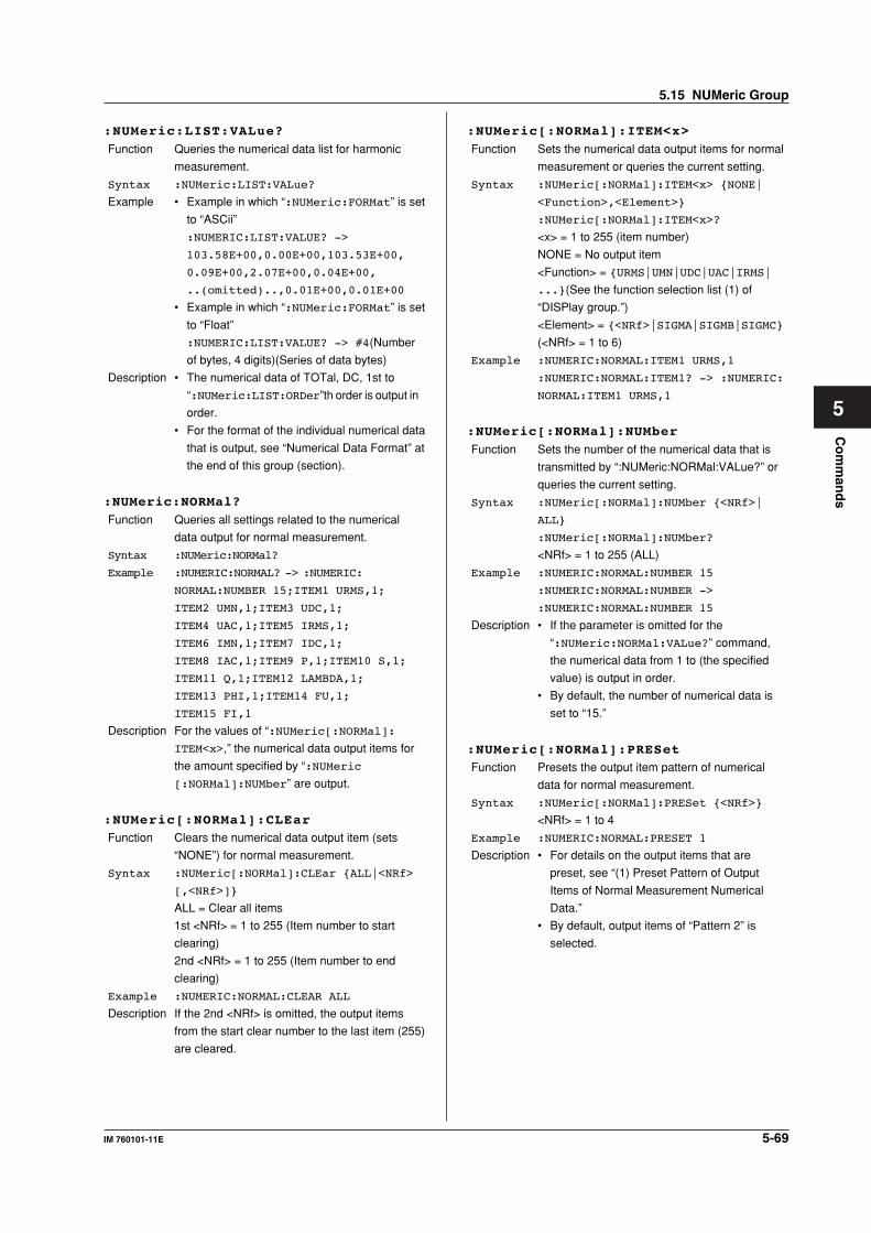
5-69IM 760101-11E
Co
mm
and
s
5
:NUMeric:LIST:VALue?
Function Queries the numerical data list for harmonic
measurement.
Syntax :NUMeric:LIST:VALue?
Example • Example in which “:NUMeric:FORMat” is set
to “ASCii”
:NUMERIC:LIST:VALUE? ->
103.58E+00,0.00E+00,103.53E+00,
0.09E+00,2.07E+00,0.04E+00,
..(omitted)..,0.01E+00,0.01E+00
• Example in which “:NUMeric:FORMat” is set
to “Float”
:NUMERIC:LIST:VALUE? -> #4(Number
of bytes, 4 digits)(Series of data bytes)
Description • The numerical data of TOTal, DC, 1st to
“:NUMeric:LIST:ORDer”th order is output in
order.
• For the format of the individual numerical data
that is output, see “Numerical Data Format” at
the end of this group (section).
:NUMeric:NORMal?
Function Queries all settings related to the numerical
data output for normal measurement.
Syntax :NUMeric:NORMal?
Example :NUMERIC:NORMAL? -> :NUMERIC:
NORMAL:NUMBER 15;ITEM1 URMS,1;
ITEM2 UMN,1;ITEM3 UDC,1;
ITEM4 UAC,1;ITEM5 IRMS,1;
ITEM6 IMN,1;ITEM7 IDC,1;
ITEM8 IAC,1;ITEM9 P,1;ITEM10 S,1;
ITEM11 Q,1;ITEM12 LAMBDA,1;
ITEM13 PHI,1;ITEM14 FU,1;
ITEM15 FI,1
Description For the values of “:NUMeric[:NORMal]:
ITEM<x>,” the numerical data output items for
the amount specified by “:NUMeric
[:NORMal]:NUMber” are output.
:NUMeric[:NORMal]:CLEar
Function Clears the numerical data output item (sets
“NONE”) for normal measurement.
Syntax :NUMeric[:NORMal]:CLEar {ALL|<NRf>
[,<NRf>]}
ALL = Clear all items
1st <NRf> = 1 to 255 (Item number to start
clearing)
2nd <NRf> = 1 to 255 (Item number to end
clearing)
Example :NUMERIC:NORMAL:CLEAR ALL
Description If the 2nd <NRf> is omitted, the output items
from the start clear number to the last item (255)
are cleared.
:NUMeric[:NORMal]:ITEM<x>
Function Sets the numerical data output items for normal
measurement or queries the current setting.
Syntax :NUMeric[:NORMal]:ITEM<x> {NONE|
<Function>,<Element>}
:NUMeric[:NORMal]:ITEM<x>?
<x> = 1 to 255 (item number)
NONE = No output item
<Function> = {URMS|UMN|UDC|UAC|IRMS|
...}(See the function selection list (1) of
“DISPlay group.”)
<Element> = {<NRf>|SIGMA|SIGMB|SIGMC}
(<NRf> = 1 to 6)
Example :NUMERIC:NORMAL:ITEM1 URMS,1
:NUMERIC:NORMAL:ITEM1? -> :NUMERIC:
NORMAL:ITEM1 URMS,1
:NUMeric[:NORMal]:NUMber
Function Sets the number of the numerical data that is
transmitted by “:NUMeric:NORMal:VALue?” or
queries the current setting.
Syntax :NUMeric[:NORMal]:NUMber {<NRf>|
ALL}
:NUMeric[:NORMal]:NUMber?
<NRf> = 1 to 255 (ALL)
Example :NUMERIC:NORMAL:NUMBER 15
:NUMERIC:NORMAL:NUMBER ->
:NUMERIC:NORMAL:NUMBER 15
Description • If the parameter is omitted for the
“:NUMeric:NORMal:VALue?” command,
the numerical data from 1 to (the specified
value) is output in order.
• By default, the number of numerical data is
set to “15.”
:NUMeric[:NORMal]:PRESet
Function Presets the output item pattern of numerical
data for normal measurement.
Syntax :NUMeric[:NORMal]:PRESet {<NRf>}
<NRf> = 1 to 4
Example :NUMERIC:NORMAL:PRESET 1
Description • For details on the output items that are
preset, see “(1) Preset Pattern of Output
Items of Normal Measurement Numerical
Data.”
• By default, output items of “Pattern 2” is
selected.
5.15 NUMeric Group
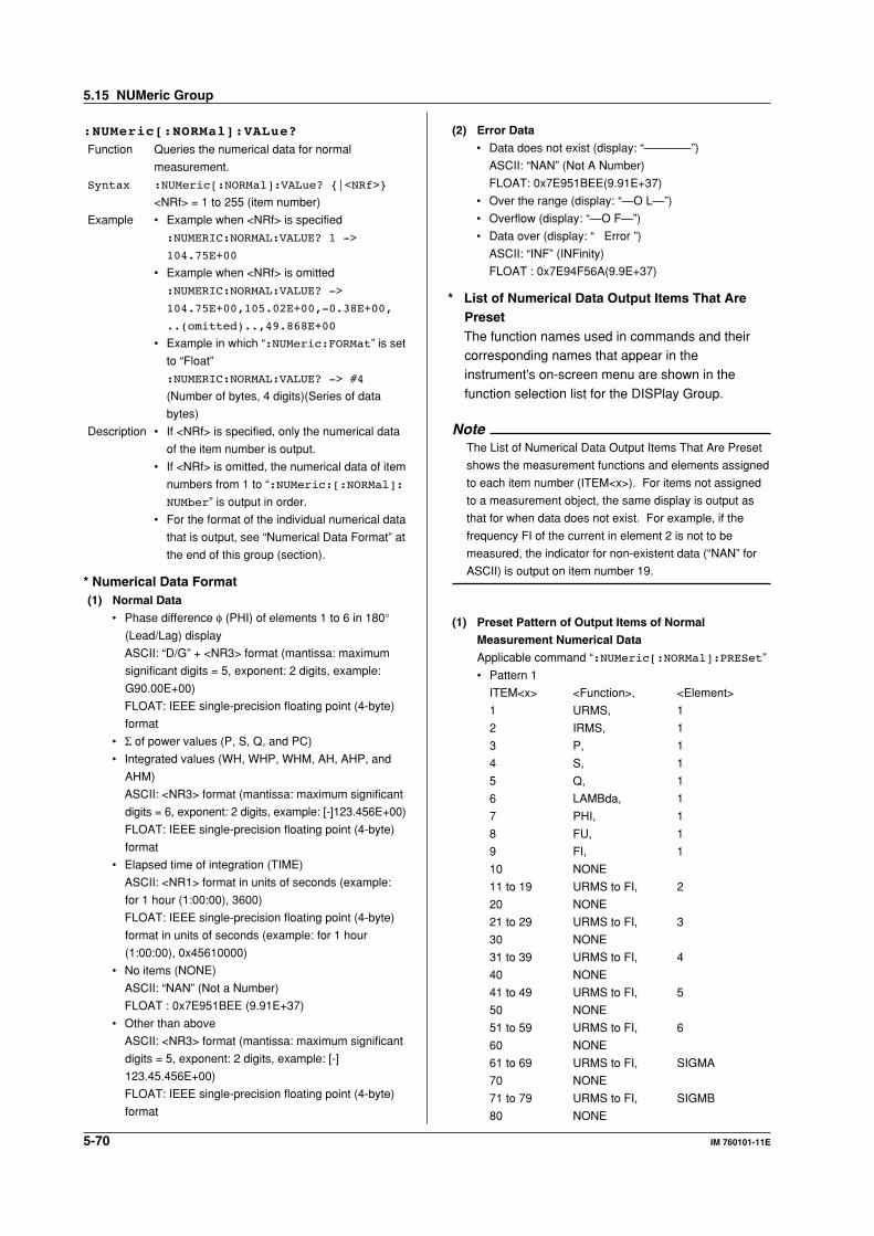
5-70 IM 760101-11E
:NUMeric[:NORMal]:VALue?
Function Queries the numerical data for normal
measurement.
Syntax :NUMeric[:NORMal]:VALue? {|<NRf>}
<NRf> = 1 to 255 (item number)
Example • Example when <NRf> is specified
:NUMERIC:NORMAL:VALUE? 1 ->
104.75E+00
• Example when <NRf> is omitted
:NUMERIC:NORMAL:VALUE? ->
104.75E+00,105.02E+00,-0.38E+00,
..(omitted)..,49.868E+00
• Example in which “:NUMeric:FORMat” is set
to “Float”
:NUMERIC:NORMAL:VALUE? -> #4
(Number of bytes, 4 digits)(Series of data
bytes)
Description • If <NRf> is specified, only the numerical data
of the item number is output.
• If <NRf> is omitted, the numerical data of item
numbers from 1 to “:NUMeric:[:NORMal]:
NUMber” is output in order.
• For the format of the individual numerical data
that is output, see “Numerical Data Format” at
the end of this group (section).
* Numerical Data Format(1) Normal Data
• Phase difference φ (PHI) of elements 1 to 6 in 180°(Lead/Lag) display
ASCII: “D/G” + <NR3> format (mantissa: maximum
significant digits = 5, exponent: 2 digits, example:
G90.00E+00)
FLOAT: IEEE single-precision floating point (4-byte)
format
• Σ of power values (P, S, Q, and PC)
• Integrated values (WH, WHP, WHM, AH, AHP, and
AHM)
ASCII: <NR3> format (mantissa: maximum significant
digits = 6, exponent: 2 digits, example: [-]123.456E+00)
FLOAT: IEEE single-precision floating point (4-byte)
format
• Elapsed time of integration (TIME)
ASCII: <NR1> format in units of seconds (example:
for 1 hour (1:00:00), 3600)
FLOAT: IEEE single-precision floating point (4-byte)
format in units of seconds (example: for 1 hour
(1:00:00), 0x45610000)
• No items (NONE)
ASCII: “NAN” (Not a Number)
FLOAT : 0x7E951BEE (9.91E+37)
• Other than above
ASCII: <NR3> format (mantissa: maximum significant
digits = 5, exponent: 2 digits, example: [-]
123.45.456E+00)
FLOAT: IEEE single-precision floating point (4-byte)
format
(2) Error Data
• Data does not exist (display: “————”)
ASCII: “NAN” (Not A Number)
FLOAT: 0x7E951BEE(9.91E+37)
• Over the range (display: “—O L—”)
• Overflow (display: “—O F—”)
• Data over (display: “ Error ”)
ASCII: “INF” (INFinity)
FLOAT : 0x7E94F56A(9.9E+37)
* List of Numerical Data Output Items That ArePresetThe function names used in commands and theircorresponding names that appear in theinstrument's on-screen menu are shown in the
function selection list for the DISPlay Group.
NoteThe List of Numerical Data Output Items That Are Preset
shows the measurement functions and elements assigned
to each item number (ITEM<x>). For items not assigned
to a measurement object, the same display is output as
that for when data does not exist. For example, if the
frequency FI of the current in element 2 is not to be
measured, the indicator for non-existent data (“NAN” for
ASCII) is output on item number 19.
(1) Preset Pattern of Output Items of Normal
Measurement Numerical Data
Applicable command “:NUMeric[:NORMal]:PRESet”
• Pattern 1
ITEM<x> <Function>, <Element>
1 URMS, 1
2 IRMS, 1
3 P, 1
4 S, 1
5 Q, 1
6 LAMBda, 1
7 PHI, 1
8 FU, 1
9 FI, 1
10 NONE
11 to 19 URMS to FI, 2
20 NONE
21 to 29 URMS to FI, 3
30 NONE
31 to 39 URMS to FI, 4
40 NONE
41 to 49 URMS to FI, 5
50 NONE
51 to 59 URMS to FI, 6
60 NONE
61 to 69 URMS to FI, SIGMA
70 NONE
71 to 79 URMS to FI, SIGMB
80 NONE
5.15 NUMeric Group
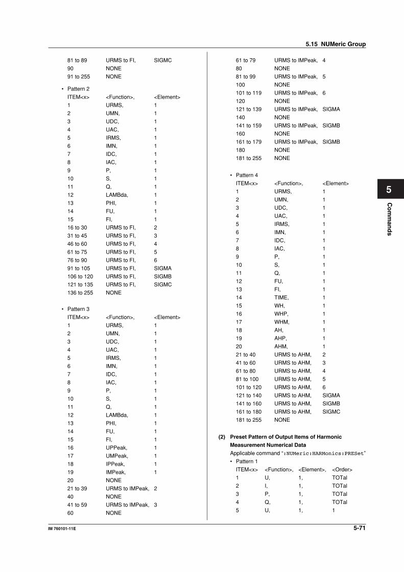
5-71IM 760101-11E
Co
mm
and
s
5
81 to 89 URMS to FI, SIGMC
90 NONE
91 to 255 NONE
• Pattern 2
ITEM<x> <Function>, <Element>
1 URMS, 1
2 UMN, 1
3 UDC, 1
4 UAC, 1
5 IRMS, 1
6 IMN, 1
7 IDC, 1
8 IAC, 1
9 P, 1
10 S, 1
11 Q, 1
12 LAMBda, 1
13 PHI, 1
14 FU, 1
15 FI, 1
16 to 30 URMS to FI, 2
31 to 45 URMS to FI, 3
46 to 60 URMS to FI, 4
61 to 75 URMS to FI, 5
76 to 90 URMS to FI, 6
91 to 105 URMS to FI, SIGMA
106 to 120 URMS to FI, SIGMB
121 to 135 URMS to FI, SIGMC
136 to 255 NONE
• Pattern 3
ITEM<x> <Function>, <Element>
1 URMS, 1
2 UMN, 1
3 UDC, 1
4 UAC, 1
5 IRMS, 1
6 IMN, 1
7 IDC, 1
8 IAC, 1
9 P, 1
10 S, 1
11 Q, 1
12 LAMBda, 1
13 PHI, 1
14 FU, 1
15 FI, 1
16 UPPeak, 1
17 UMPeak, 1
18 IPPeak, 1
19 IMPeak, 1
20 NONE
21 to 39 URMS to IMPeak, 2
40 NONE
41 to 59 URMS to IMPeak, 3
60 NONE
61 to 79 URMS to IMPeak, 4
80 NONE
81 to 99 URMS to IMPeak, 5
100 NONE
101 to 119 URMS to IMPeak, 6
120 NONE
121 to 139 URMS to IMPeak, SIGMA
140 NONE
141 to 159 URMS to IMPeak, SIGMB
160 NONE
161 to 179 URMS to IMPeak, SIGMB
180 NONE
181 to 255 NONE
• Pattern 4
ITEM<x> <Function>, <Element>
1 URMS, 1
2 UMN, 1
3 UDC, 1
4 UAC, 1
5 IRMS, 1
6 IMN, 1
7 IDC, 1
8 IAC, 1
9 P, 1
10 S, 1
11 Q, 1
12 FU, 1
13 FI, 1
14 TIME, 1
15 WH, 1
16 WHP, 1
17 WHM, 1
18 AH, 1
19 AHP, 1
20 AHM, 1
21 to 40 URMS to AHM, 2
41 to 60 URMS to AHM, 3
61 to 80 URMS to AHM, 4
81 to 100 URMS to AHM, 5
101 to 120 URMS to AHM, 6
121 to 140 URMS to AHM, SIGMA
141 to 160 URMS to AHM, SIGMB
161 to 180 URMS to AHM, SIGMC
181 to 255 NONE
(2) Preset Pattern of Output Items of Harmonic
Measurement Numerical Data
Applicable command “:NUMeric:HARMonics:PRESet”
• Pattern 1
ITEM<x> <Function>, <Element>, <Order>
1 U, 1, TOTal
2 I, 1, TOTal
3 P, 1, TOTal
4 Q, 1, TOTal
5 U, 1, 1
5.15 NUMeric Group
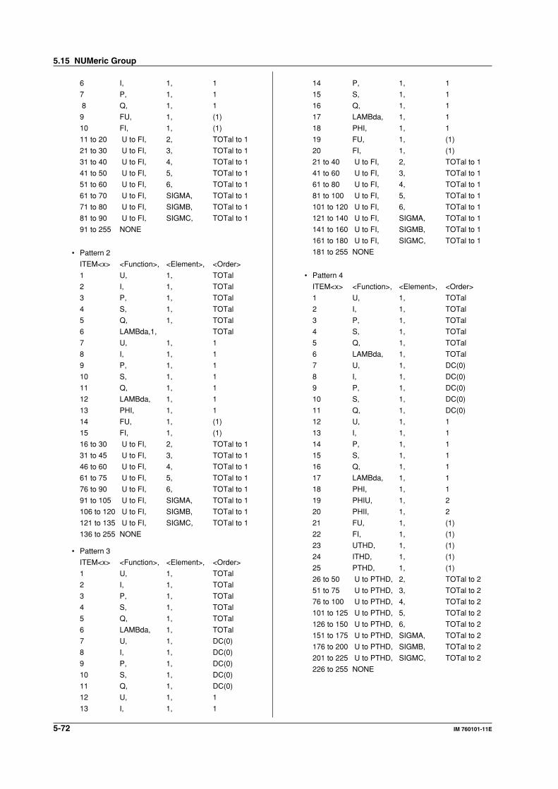
5-72 IM 760101-11E
6 I, 1, 1
7 P, 1, 1
8 Q, 1, 1
9 FU, 1, (1)
10 FI, 1, (1)
11 to 20 U to FI, 2, TOTal to 1
21 to 30 U to FI, 3, TOTal to 1
31 to 40 U to FI, 4, TOTal to 1
41 to 50 U to FI, 5, TOTal to 1
51 to 60 U to FI, 6, TOTal to 1
61 to 70 U to FI, SIGMA, TOTal to 1
71 to 80 U to FI, SIGMB, TOTal to 1
81 to 90 U to FI, SIGMC, TOTal to 1
91 to 255 NONE
• Pattern 2
ITEM<x> <Function>, <Element>, <Order>
1 U, 1, TOTal
2 I, 1, TOTal
3 P, 1, TOTal
4 S, 1, TOTal
5 Q, 1, TOTal
6 LAMBda,1, TOTal
7 U, 1, 1
8 I, 1, 1
9 P, 1, 1
10 S, 1, 1
11 Q, 1, 1
12 LAMBda, 1, 1
13 PHI, 1, 1
14 FU, 1, (1)
15 FI, 1, (1)
16 to 30 U to FI, 2, TOTal to 1
31 to 45 U to FI, 3, TOTal to 1
46 to 60 U to FI, 4, TOTal to 1
61 to 75 U to FI, 5, TOTal to 1
76 to 90 U to FI, 6, TOTal to 1
91 to 105 U to FI, SIGMA, TOTal to 1
106 to 120 U to FI, SIGMB, TOTal to 1
121 to 135 U to FI, SIGMC, TOTal to 1
136 to 255 NONE
• Pattern 3
ITEM<x> <Function>, <Element>, <Order>
1 U, 1, TOTal
2 I, 1, TOTal
3 P, 1, TOTal
4 S, 1, TOTal
5 Q, 1, TOTal
6 LAMBda, 1, TOTal
7 U, 1, DC(0)
8 I, 1, DC(0)
9 P, 1, DC(0)
10 S, 1, DC(0)
11 Q, 1, DC(0)
12 U, 1, 1
13 I, 1, 1
14 P, 1, 1
15 S, 1, 1
16 Q, 1, 1
17 LAMBda, 1, 1
18 PHI, 1, 1
19 FU, 1, (1)
20 FI, 1, (1)
21 to 40 U to FI, 2, TOTal to 1
41 to 60 U to FI, 3, TOTal to 1
61 to 80 U to FI, 4, TOTal to 1
81 to 100 U to FI, 5, TOTal to 1
101 to 120 U to FI, 6, TOTal to 1
121 to 140 U to FI, SIGMA, TOTal to 1
141 to 160 U to FI, SIGMB, TOTal to 1
161 to 180 U to FI, SIGMC, TOTal to 1
181 to 255 NONE
• Pattern 4
ITEM<x> <Function>, <Element>, <Order>
1 U, 1, TOTal
2 I, 1, TOTal
3 P, 1, TOTal
4 S, 1, TOTal
5 Q, 1, TOTal
6 LAMBda, 1, TOTal
7 U, 1, DC(0)
8 I, 1, DC(0)
9 P, 1, DC(0)
10 S, 1, DC(0)
11 Q, 1, DC(0)
12 U, 1, 1
13 I, 1, 1
14 P, 1, 1
15 S, 1, 1
16 Q, 1, 1
17 LAMBda, 1, 1
18 PHI, 1, 1
19 PHIU, 1, 2
20 PHII, 1, 2
21 FU, 1, (1)
22 FI, 1, (1)
23 UTHD, 1, (1)
24 ITHD, 1, (1)
25 PTHD, 1, (1)
26 to 50 U to PTHD, 2, TOTal to 2
51 to 75 U to PTHD, 3, TOTal to 2
76 to 100 U to PTHD, 4, TOTal to 2
101 to 125 U to PTHD, 5, TOTal to 2
126 to 150 U to PTHD, 6, TOTal to 2
151 to 175 U to PTHD, SIGMA, TOTal to 2
176 to 200 U to PTHD, SIGMB, TOTal to 2
201 to 225 U to PTHD, SIGMC, TOTal to 2
226 to 255 NONE
5.15 NUMeric Group
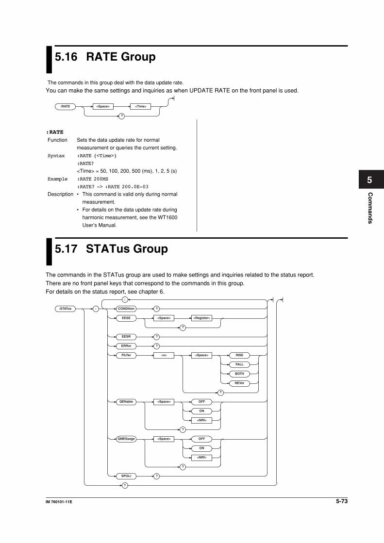
5-73IM 760101-11E
Co
mm
and
s
5
5.16 RATE Group
The commands in this group deal with the data update rate.
You can make the same settings and inquiries as when UPDATE RATE on the front panel is used.
:RATE <Space> <Time>
?
:RATE
Function Sets the data update rate for normal
measurement or queries the current setting.
Syntax :RATE {<Time>}
:RATE?
<Time> = 50, 100, 200, 500 (ms), 1, 2, 5 (s)
Example :RATE 200MS
:RATE? -> :RATE 200.0E-03
Description • This command is valid only during normal
measurement.
• For details on the data update rate during
harmonic measurement, see the WT1600
User’s Manual.
5.17 STATus Group
The commands in the STATus group are used to make settings and inquiries related to the status report.
There are no front panel keys that correspond to the commands in this group.For details on the status report, see chapter 6.
:STATus :
;
CONDition ?
EESE <Space> <Register>
?
EESR ?
ERRor ?
FILTer <x> <Space> RISE
FALL
BOTH
NEVer
?
QENable <Space> OFF
ON
<NRf>
?
QMESsage <Space> OFF
ON
<NRf>
?
SPOLl ?
?
5-74 IM 760101-11E
:STATus?
Function Queries all settings related to the
communication status function.
Syntax :STATus?
Example :STATUS? -> :STATUS:EESE 0;FILTER1
NEVER;FILTER2 NEVER;FILTER3 NEVER;
FILTER4 NEVER;FILTER5 NEVER;
FILTER6 NEVER;FILTER7 NEVER;
FILTER8 NEVER;FILTER9 NEVER;
FILTER10 NEVER;FILTER11 NEVER;
FILTER12 NEVER;FILTER13 NEVER;
FILTER14 NEVER;FILTER15 NEVER;
FILTER16 NEVER;QENABLE 0;QMESSAGE 1
:STATus:CONDition?
Function Queries the contents of the condition register.
Syntax :STATus:CONDition?
Example :STATUS:CONDITION? -> 16
Description For the description regarding how to
synchronize the program using :STATus:
CONDition, see page 4-8.
:STATus:EESE
(Extended Event Status Enable register)
Function Sets the extended event enable register or
queries the current setting.
Syntax :STATus:EESE <Register>
:STATus:EESE?
<Register> = 0 to 65535
Example :STATUS:EESE #B0000000000000000
:STATUS:EESE? -> :STATUS:EESE 0
:STATus:EESR?
(Extended Event Status Register)
Function Queries the content of the extended event
register and clears the register.
Syntax :STATus:EESR?
Example :STATUS:EESR? -> 0
:STATus:ERRor?
Function Queries the error code and message
information (top of the error queue).
Syntax :STATus:ERRor?
Example :STATUS:ERROR? ->
113,"Underfined Header"
Description • When there is no error, “0, “No error”” is
returned.
• The message cannot be returned in
Japanese.
• You can specify whether or not to add the
message using the “STATus:QMESsage”
command.
:STATus:FILTer<x>
Function Sets the transition filter or queries the current
setting.
Syntax :STATus:FILTer<x> {RISE|FALL|BOTH|
NEVer}
:STATus:FILTer<x>?
<x> = 1 to 16
Example :STATUS:FILTER2 RISE
:STATUS:FILTER2? -> :STATUS:
FILTER2 RISE
Description Specify how each bit of the condition register is
to change to set the event. If “RISE” is specified,
the event is set when the bit changes from “0” to
“1.”
:STATus:QENable
Function Sets whether or not to store messages other
than errors to the error queue (ON/OFF) or
queries the current setting.
Syntax :STATus:QENable {<Boolean>}
:STATus:QENable?
Example :STATUS:QENABLE ON
:STATUS:QENABLE? -> :STATUS:
QENABLE 1
:STATus:QMESsage
Function Sets whether or not to attach message
information to the response to the
“STATus:ERRor?” query (ON/OFF) or queries
the current setting.
Syntax :STATus:QMESsage {<Boolean>}
:STATus:QMESsage?
Example :STATUS:QMESSAGE ON
:STATUS:QMESSAGE? -> :STATUS:
QMESSAGE 1
:STATus:SPOLI? (Serial Poll)
Function Executes serial polling.
Syntax :STATus:SPOLl?
Example :STATUS:SPOLL? -> :STATUS:SPOLL 0
Description This is a command specific to the serial (RS-
232) interface. An interface message is
available for the GP-IB interface.
5.17 STATus Group
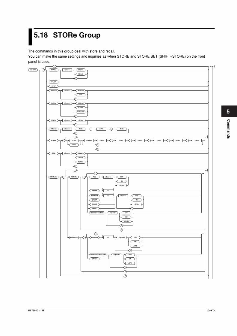
5-75IM 760101-11E
Co
mm
and
s
5
5.18 STORe Group
The commands in this group deal with store and recall.You can make the same settings and inquiries as when STORE and STORE SET (SHIFT+STORE) on the front
panel is used.
:STORe :
;
MODE <Space> STORe
RECall
?
STOP
DIRection <Space> MEMor y
FILE
?
SMODe <Space> MANual
RTIMe
INTEGrate
?
COUNt <Space> <NRf>
?
INTer val <Space> <NRf> , <NRf> , <NRf>
?
RTIMe : STARt <Space> <NRf> , <NRf> , <NRf> , <NRf> , ,<NRf> <NRf>
?END
?
ITEM <Space> NUMeric
WAVE
NWAV e
?
NUMeric : NORMal : ALL <Space> OFF
ON
<NRf>
PRESet <x>
ELEMent <x> <Space> OFF
ON
<NRf>
?
SIGMA
SIGMB
SIGMC
<Normal-Function> <Space> OFF
ON
<NRf>
?
?
HARMonics : ELEMent <x> <Space> OFF
ON
<NRf>
?
<Harmonics-Function> <Space> OFF
ON
<NRf>
?
OTHers
?
?
STARt
;
;
;
;
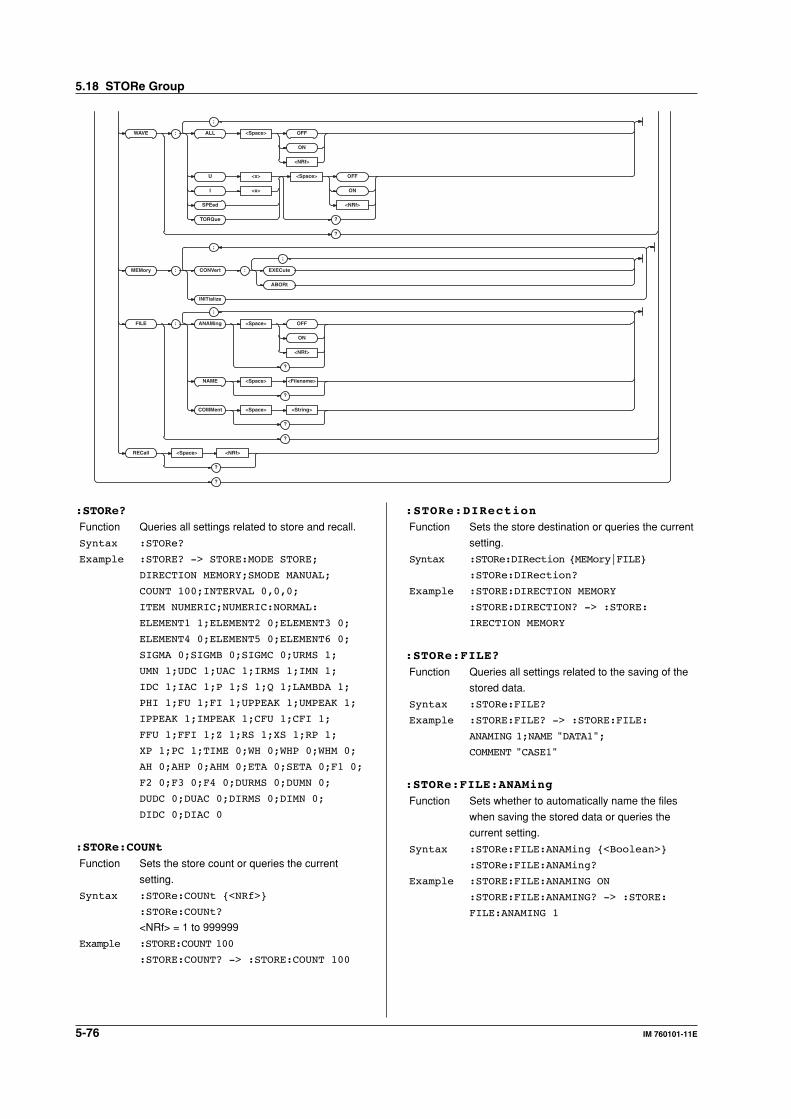
5-76 IM 760101-11E
WAVE : ALL <Space> OFF
ON
<NRf>
U <x> <Space> OFF
ON
<NRf>
?
I <x>
SPEed
TORQue
?
MEMor y : CONVer t : EXECute
ABORt
INITializ e
FILE : ANAMing <Space> OFF
ON
<NRf>
?
NAME <Space> <Filename>
?
COMMent <Space> <String>
?
?
RECall <Space> <NRf>
?
?
;
;
;
;
:STORe:DIRection
Function Sets the store destination or queries the current
setting.
Syntax :STORe:DIRection {MEMory|FILE}
:STORe:DIRection?
Example :STORE:DIRECTION MEMORY
:STORE:DIRECTION? -> :STORE:
IRECTION MEMORY
:STORe:FILE?
Function Queries all settings related to the saving of the
stored data.
Syntax :STORe:FILE?
Example :STORE:FILE? -> :STORE:FILE:
ANAMING 1;NAME "DATA1";
COMMENT "CASE1"
:STORe:FILE:ANAMing
Function Sets whether to automatically name the files
when saving the stored data or queries the
current setting.
Syntax :STORe:FILE:ANAMing {<Boolean>}
:STORe:FILE:ANAMing?
Example :STORE:FILE:ANAMING ON
:STORE:FILE:ANAMING? -> :STORE:
FILE:ANAMING 1
:STORe?
Function Queries all settings related to store and recall.
Syntax :STORe?
Example :STORE? -> STORE:MODE STORE;
DIRECTION MEMORY;SMODE MANUAL;
COUNT 100;INTERVAL 0,0,0;
ITEM NUMERIC;NUMERIC:NORMAL:
ELEMENT1 1;ELEMENT2 0;ELEMENT3 0;
ELEMENT4 0;ELEMENT5 0;ELEMENT6 0;
SIGMA 0;SIGMB 0;SIGMC 0;URMS 1;
UMN 1;UDC 1;UAC 1;IRMS 1;IMN 1;
IDC 1;IAC 1;P 1;S 1;Q 1;LAMBDA 1;
PHI 1;FU 1;FI 1;UPPEAK 1;UMPEAK 1;
IPPEAK 1;IMPEAK 1;CFU 1;CFI 1;
FFU 1;FFI 1;Z 1;RS 1;XS 1;RP 1;
XP 1;PC 1;TIME 0;WH 0;WHP 0;WHM 0;
AH 0;AHP 0;AHM 0;ETA 0;SETA 0;F1 0;
F2 0;F3 0;F4 0;DURMS 0;DUMN 0;
DUDC 0;DUAC 0;DIRMS 0;DIMN 0;
DIDC 0;DIAC 0
:STORe:COUNt
Function Sets the store count or queries the current
setting.
Syntax :STORe:COUNt {<NRf>}
:STORe:COUNt?
<NRf> = 1 to 999999
Example :STORE:COUNT 100
:STORE:COUNT? -> :STORE:COUNT 100
5.18 STORe Group
5-77IM 760101-11E
Co
mm
and
s
5
:STORe:FILE:COMMent
Function Sets the comment to be added to the file when
saving the stored data or queries the current
setting.
Syntax :STORe:FILE:COMMent {<String>}
:STORe:FILE:COMMent?
<string> = 25 characters or less
Example :STORE:FILE:COMMENT "CASE1"
:STORE:FILE:COMMENT? ->
:STORE:FILE:COMMENT "CASE1"
:STORe:FILE:NAME
Function Sets the name of the file when saving the stored
data or queries the current setting.
Syntax :STORe:FILE:NAME {<Filename>}
:STORe:FILE:NAME?
Example :STORE:FILE:NAME "DATA1"
:STORE:FILE:NAME? -> :STORE:FILE:
NAME "DATA1"
Description The save destination of the stored data is
specified using:
• the “:FILE:DRIVe” command for the drive.
• the “:FILE:CDIRectory” command for the
directory.
The save destination path can be queried
using the “:FILE:PATH?” command.
:STORe:INTerval
Function Sets the store interval or queries the current
setting.
Syntax :STORe:INTerval {<NRf>,<NRf>,<NRf>}
:STORe:INTerval?
1st <NRf> = 0 to 99 (hour)
2nd <NRf> = 0 to 59 (minute)
3rd <NRf> = 1 to 59 (second)
Example :STORE:INTERVAL 0,0,0
:STORE:INTERVAL? -> :STORE:
INTERVAL 0,0,0
:STORe:ITEM
Function Sets the items to be stored or queries the
current setting.
Syntax :STORe:ITEM {NUMeric|WAVE|NWAVe}
:STORe:ITEM?
NUMeric = Store only the numerical values.
WAVE = Store only the waveforms.
NWAVe = Store both the numerical values and
the waveforms.
Example :STORE:ITEM NUMERIC
:STORE:ITEM? -> :STORE:ITEM NUMERIC
:STORe:MEMory:CONVert:ABORt
Function Abort converting the stored data from the
memory to the file.
Syntax :STORe:MEMory:CONVert:ABORt
Example :STORE:MEMORY:CONVERT:ABORT
:STORe:MEMory:CONVert:EXECute
Function Executes the converting of the stored data from
the memory to the file.
Syntax :STORe:MEMory:CONVert:EXECute
Example :STORE:MEMORY:CONVERT:EXECUTE
Description • The convert destination file is set using the
“:STORe:FILE:...” command.
• When executing file conversion, the
instrument accesses the file twice.
When checking the completion status of the
file conversion, you must use the
“COMMUNICATE: WAIT 64” command
(checks for changes in bit 6 (ACS) of the
status register) two times as in the following
example.
"STATUS:EESR?"
Clears the extended event register.
"STORE:MEMORY:CONVERT:EXECUTE"
Starts file conversion.
"COMMUNICATE:WAIT 64"
Waits for conversion to complete, 1st time.
"STATUS:EESR?"
Clears the extended event register.
"COMMUNICATE:WAIT 64"
Waits for conversion to complete, 2nd time.
"STATUS:EESR?"
Clears the extended event register.
:STORe:MEMory:INITialize
Function Executes the initialization of the storage
memory.
Syntax :STORe:MEMory:INITialize
Example :STORE:MEMORY:INITIALIZE
:STORe:MODE
Function Sets the data storage/recall or queries the
current setting.
Syntax :STORe:MODE {STORe|RECall}
:STORe:MODE?
Example :STORE:MODE STORE
:STORE:MODE? -> :STORE:MODE STORE
:STORe:NUMeric?
Function Queries all settings related to the storage of
numerical data.
Syntax :STORe:NUMeric?
Example :STORE:NUMERIC? -> :STORE:NUMERIC:
NORMAL:ELEMENT1 1;ELEMENT2 0;ELEMENT3 0;ELEMENT4 0;ELEMENT5 0;ELEMENT6 0;SIGMA 0;SIGMB 0;SIGMC 0;URMS 1;UMN 1;UDC 1;UAC 1;IRMS 1;IMN 1;IDC 1;IAC 1;P 1;S 1;Q 1;LAMBDA 1;PHI 1;FU 1;FI 1;UPPEAK 1;UMPEAK 1;IPPEAK 1;IMPEAK 1;CFU 1;CFI 1;FFU 1;FFI 1;Z 1;RS 1;XS 1;RP 1;XP 1;PC 1;TIME 0;WH 0;WHP 0;WHM 0;AH 0;AHP 0;AHM 0;ETA 0;SETA 0;F1 0;F2 0;F3 0;F4 0;DURMS 0;DUMN 0;DUDC 0;DUAC 0;DIRMS 0;
DIMN 0;DIDC 0;DIAC 0
5.18 STORe Group
5-78 IM 760101-11E
:STORe:NUMeric:HARMonics?
Function Queries all settings related to the storage of the
numerical data list for harmonic measurement.
Syntax :STORe:NUMeric:HARMonics?
Example :STORE:NUMERIC:HARMONICS? ->
:STORE:NUMERIC:HARMONICS:
ELEMENT1 1;ELEMENT2 0;ELEMENT3 0;
ELEMENT4 0;ELEMENT5 0;ELEMENT6 0;
U 1;I 0;P 0;S 0;Q 0;LAMBDA 0;PHI 0;
PHIU 0;PHII 0;Z 0;RS 0;XS 0;RP 0;
XP 0;OTHERS 0
:STORe:NUMeric:HARMonics:ELEMent<x>
Function Turns ON/OFF the output of the element when
storing the numerical data during harmonic
measurement or queries the current setting.
Syntax :STORe:NUMeric:HARMonics:
ELEMent<x> {<Boolean>}
:STORe:NUMeric:HARMonics:
ELEMent<x>?
<x> = 1 to 6
Example :STORE:NUMERIC:HARMONICS:
ELEMENT1 ON
:STORE:NUMERIC:HARMONICS:
ELEMENT1? -> :STORE:NUMERIC:
HARMONICS:ELEMENT1 1
:STORe:NUMeric:HARMonics:{<Harmonic
measurement function>|OTHers}
Function Turns ON/OFF the output of the function when
storing the numerical data during harmonic
measurement or queries the current setting.
Syntax :STORe:NUMeric:HARMonics:{<Harmonic
measurement function>|OTHers}
{<Boolean>}
:STORe:NUMeric:HARMonics:{<Harmonic
measurement function>|OTHers}?
<Harmonic measurement function> = {U|I|P|
S|Q|LAMBda...} (See the function selection list
(3) of “DISPlay group.”)
Example :STORE:NUMERIC:HARMONICS:U ON
:STORE:NUMERIC:HARMONICS:U? ->
:STORE:NUMERIC:HARMONICS:U 1
Description The command and query using “:STORE:
NUMeric:HARMonics:OTHers” is valid on
models with two or more elements.
:STORe:NUMeric:NORMal?
Function Queries all settings related to the storage of the
numerical data for normal measurement.
Syntax :STORe:NUMeric:NORMal?
Example :STORE:NUMERIC:NORMAL? -> :STORE:
NUMERIC:NORMAL:ELEMENT1 1;
ELEMENT2 0;ELEMENT3 0;ELEMENT4 0;
ELEMENT5 0;ELEMENT6 0;SIGMA 0;
SIGMB 0;SIGMC 0;URMS 1;UMN 1;UDC 1;
UAC 1;IRMS 1;IMN 1;IDC 1;IAC 1;P 1;
S 1;Q 1;LAMBDA 1;PHI 1;FU 1;FI 1;
UPPEAK 1;UMPEAK 1;IPPEAK 1;
IMPEAK 1;CFU 1;CFI 1;FFU 1;FFI 1;
Z 1;RS 1;XS 1;RP 1;XP 1;PC 1;
TIME 0;WH 0;WHP 0;WHM 0;AH 0;AHP 0;
AHM 0;ETA 0;SETA 0;F1 0;F2 0;F3 0;
F4 0;DURMS 0;DUMN 0;DUDC 0;DUAC 0;
DIRMS 0;DIMN 0;DIDC 0;DIAC 0
:STORe:NUMeric:NORMal:ALL
Function Collectively turns ON/OFF the output of all
elements and functions when storing the
numerical data during normal measurement.
Syntax :STORe:NUMeric:NORMal:
ALL {<Boolean>}
Example :STORE:NUMERIC:NORMAL:ALL ON
:STORe:NUMeric:NORMal:{ELEMent<x>|SIGMA|
SIGMB|SIGMC}
Function Turns ON/OFF the output of the
{element|ΣA|ΣB|ΣC} when storing the numerical
data during normal measurement or queries the
current setting.
Syntax :STORe:NUMeric:NORMal:{ELEMent<x>|
SIGMA|SIGMB|SIGMC} {<Boolean>}
:STORe:NUMeric:NORMal:{ELEMent<x>|
SIGMA|SIGMB|SIGMC}?
<x> = 1 to 6
Example :STORE:NUMERIC:NORMAL:ELEMENT1 ON
:STORE:NUMERIC:NORMAL:ELEMENT1? ->
:STORE:NUMERIC:NORMAL:ELEMENT1 1
Description • The command and query using
“:STORE:NUMeric:NORMal:SIGMB” is valid
on models with two or more elements.
• The command and query using “:STORE:
NUMeric:NORMal:SIGMC” is valid on
models with three or more elements.
:STORe:NUMeric:NORMal:PRESet<x>
Function Presets the output ON/OFF pattern of the
element and function when saving the numerical
data to a file during normal measurement.
Syntax :STORe:NUMeric:NORMal:PRESet<x>
<x> = 1 to 2 (preset pattern number)
Example :STORE:NUMERIC:NORMAL:PRESET1
Description For details on the storage pattern when preset
is executed, see the WT1600 User’s Manual.
5.18 STORe Group
5-79IM 760101-11E
Co
mm
and
s
5
:STORe:NUMeric:NORMal:<Normal
measurement function>
Function Turns ON/OFF the output of the function when
storing the numerical data during normal
measurement or queries the current setting.
Syntax :STORe:NUMeric:NORMal:<Normal
measurement function> {<Boolean>}
:STORe:NUMeric:NORMal:<Normal
measurement function>?
<Normal measurement function> = {URMS|
UMN|UDC|UAC|IRMS|...} (See the function
selection list (1) of “DISPlay group.”)
Example :STORE:NUMERIC:NORMAL:URMS ON
:STORE:NUMERIC:NORMAL:URMS? ->
:STORE:NUMERIC:NORMAL:URMS 1
:STORe:RECall
Function Sets the data number to be recalled or queries
the current setting.
Syntax :STORe:RECall {<NRf>}
:STORe:RECall?
<NRf> = 1 to 999999
Example :STORE:RECALL 1
:STORE:RECALL? -> :STORE:RECALL 1
:STORe:RTIMe?
Function Queries the store start and stop date/time for
real-time store mode.
Syntax :STORe:RTIMe?
Example :STORE:RTIME? -> :STORE:RTIME:
START 2001,1,1,0,0,0;
END 2001,1,1,1,0,0
:STORe:RTIMe:{STARt|END}
Function Sets the store {start|stop} date/time for real-time
store mode or queries the current setting.
Syntax :STORe:RTIMe:{STARt|END} {<NRf>,
<NRf>,<NRf>,<NRf>,<NRf>,<NRf>}
:STORe:RTIMe:{STARt|END}?
{<NRf>, <NRf>, <NRf>, <NRf>, <NRf>, <NRf>}
= 2001, 1, 1, 0, 0, 0 to 2099, 12, 31, 23, 59, 59
1st <NRf> = 2001 to 2099 (year)
2nd <NRf> = 1 to 12 (month)
3rd <NRf> = 1 to 31 (day)
4th <NRf> = 0 to 23 (hour)
5th <NRf> = 0 to 59 (minute)
6th <NRf> = 0 to 59 (second)
Example :STORE:RTIME:START 2001,1,1,0,0,0
:STORE:RTIME:START? -> :STORE:
RTIME:START 2001,1,1,0,0,0
:STORe:SMODe
Function Sets the store mode or queries the current
setting.
Syntax :STORe:SMODe {MANual|RTIMe|
INTEGrate}
:STORe:SMODe?
MANual = Manual store mode
RTIMe = Real-time store mode
INTEGrate = Integration synchronization store
mode
Example :STORE:SMODE MANUAL
:STORE:SMODE? -> :STORE:
SMODE MANUAL
:STORe:STARt
Function Starts the data store operation.
Syntax :STORe:STARt
Example :STORE:START
Description When “:STORe:SMODe” is set to MANual, the
store operation is executed. When set to
{RTIMe|INTEGrate} the WT1600 enters the
store wait state.
:STORe:STOP
Function Stops the data store operation.
Syntax :STORe:STOP
Example :STORE:STOP
:STORe:WAVE?
Function Queries all settings related to the storage of
waveform display data.
Syntax :STORe:WAVE?
Example :STORE:WAVE? -> :STORE:WAVE:U1 1;
U2 0;U3 0;U4 0;U5 0;U6 0;I1 1;I2 0;
I3 0;I4 0;I5 0;I6 0
:STORe:WAVE:ALL
Function Collectively turns ON/OFF the output of all
waveforms when storing waveform display data.
Syntax :STORe:WAVE:ALL {<Boolean>}
Example :STORE:WAVE:ALL ON
:STORe:WAVE:{U<x>|I<x>|SPEed|TORQue}
Function Turns ON/OFF the output of the waveform when
storing the waveform display data or queries the
current setting.
Syntax :STORe:WAVE:{U<x>|I<x>|SPEed|
TORQue} {<Boolean>}
:STORe:WAVE:{U<x>|I<x>|SPEed|
TORQue}?
<x> = 1 to 6
Example :STORE:WAVE:U1 ON
:STORE:WAVE:U1? -> :STORE:WAVE:U1 1
Description {SPEed|TORQue} is valid only when the motor
evaluation function (/MTR option) is installed.
5.18 STORe Group
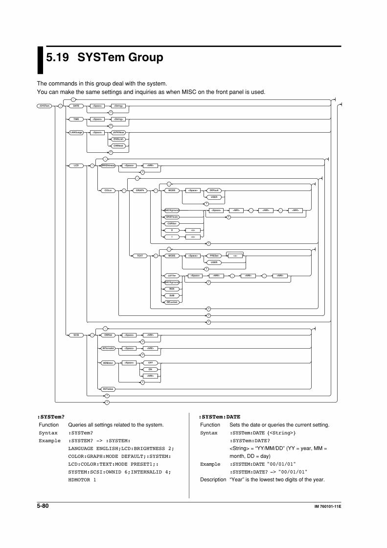
5-80 IM 760101-11E
5.19 SYSTem Group
The commands in this group deal with the system.You can make the same settings and inquiries as when MISC on the front panel is used.
:SYSTem :
;
DATE <Space> <String>
?
TIME <Space> <String>
?
LANGuage <Space> JAPANese
ENGLish
CHINese
?
LCD : BRIGhtness <Space> <NRf>
?
COLor : GRAPh : MODE <Space> DEFault
USER
?
BACKground <Space> <NRf> , <NRf> , <NRf>
?GRATicule
CURSor
U <x>
I <x>
?
TEXT : MODE <Space> PRESet <x>
USER
?
LETTer <Space> <NRf> , <NRf> , <NRf>
?BACKground
BOX
SUB
SELected
?
?
?
SCSI : OWNid <Space> <NRf>
?
INTernalid <Space> <NRf>
<NRf>
?
INITializ e
?
?
HDMotor <Space> OFF
ON
?
;
;
;
;
;
:SYSTem:DATE
Function Sets the date or queries the current setting.
Syntax :SYSTem:DATE {<String>}
:SYSTem:DATE?
<String> = “YY/MM/DD” (YY = year, MM =
month, DD = day)
Example :SYSTEM:DATE "00/01/01"
:SYSTEM:DATE? -> "00/01/01"
Description “Year” is the lowest two digits of the year.
:SYSTem?
Function Queries all settings related to the system.
Syntax :SYSTem?
Example :SYSTEM? -> :SYSTEM:
LANGUAGE ENGLISH;LCD:BRIGHTNESS 2;
COLOR:GRAPH:MODE DEFAULT;:SYSTEM:
LCD:COLOR:TEXT:MODE PRESET1;:
SYSTEM:SCSI:OWNID 6;INTERNALID 4;
HDMOTOR 1
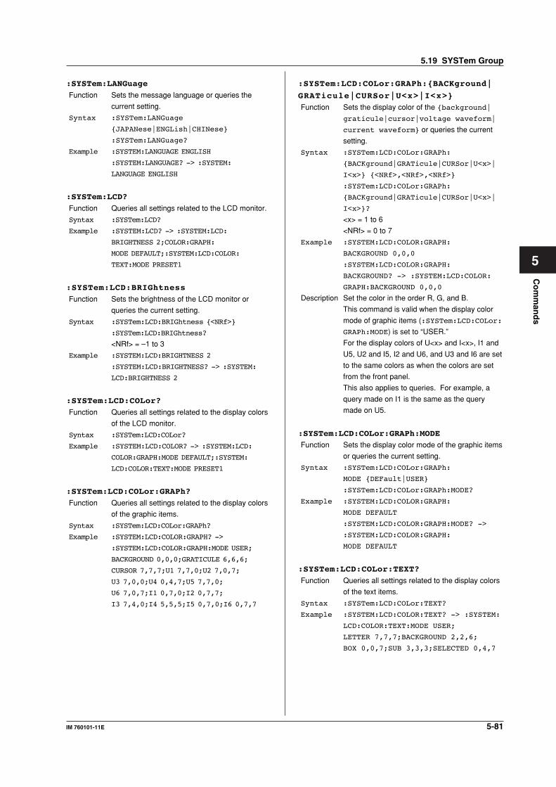
5-81IM 760101-11E
Co
mm
and
s
5
:SYSTem:LANGuage
Function Sets the message language or queries the
current setting.
Syntax :SYSTem:LANGuage
{JAPANese|ENGLish|CHINese}
:SYSTem:LANGuage?
Example :SYSTEM:LANGUAGE ENGLISH
:SYSTEM:LANGUAGE? -> :SYSTEM:
LANGUAGE ENGLISH
:SYSTem:LCD?
Function Queries all settings related to the LCD monitor.
Syntax :SYSTem:LCD?
Example :SYSTEM:LCD? -> :SYSTEM:LCD:
BRIGHTNESS 2;COLOR:GRAPH:
MODE DEFAULT;:SYSTEM:LCD:COLOR:
TEXT:MODE PRESET1
:SYSTem:LCD:BRIGhtness
Function Sets the brightness of the LCD monitor or
queries the current setting.
Syntax :SYSTem:LCD:BRIGhtness {<NRf>}
:SYSTem:LCD:BRIGhtness?
<NRf> = –1 to 3
Example :SYSTEM:LCD:BRIGHTNESS 2
:SYSTEM:LCD:BRIGHTNESS? -> :SYSTEM:
LCD:BRIGHTNESS 2
:SYSTem:LCD:COLor?
Function Queries all settings related to the display colors
of the LCD monitor.
Syntax :SYSTem:LCD:COLor?
Example :SYSTEM:LCD:COLOR? -> :SYSTEM:LCD:
COLOR:GRAPH:MODE DEFAULT;:SYSTEM:
LCD:COLOR:TEXT:MODE PRESET1
:SYSTem:LCD:COLor:GRAPh?
Function Queries all settings related to the display colors
of the graphic items.
Syntax :SYSTem:LCD:COLor:GRAPh?
Example :SYSTEM:LCD:COLOR:GRAPH? ->
:SYSTEM:LCD:COLOR:GRAPH:MODE USER;
BACKGROUND 0,0,0;GRATICULE 6,6,6;
CURSOR 7,7,7;U1 7,7,0;U2 7,0,7;
U3 7,0,0;U4 0,4,7;U5 7,7,0;
U6 7,0,7;I1 0,7,0;I2 0,7,7;
I3 7,4,0;I4 5,5,5;I5 0,7,0;I6 0,7,7
:SYSTem:LCD:COLor:GRAPh:{BACKground|
GRATicule|CURSor|U<x>|I<x>}
Function Sets the display color of the {background|
graticule|cursor|voltage waveform|
current waveform} or queries the current
setting.
Syntax :SYSTem:LCD:COLor:GRAPh:
{BACKground|GRATicule|CURSor|U<x>|
I<x>} {<NRf>,<NRf>,<NRf>}
:SYSTem:LCD:COLor:GRAPh:
{BACKground|GRATicule|CURSor|U<x>|
I<x>}?
<x> = 1 to 6
<NRf> = 0 to 7
Example :SYSTEM:LCD:COLOR:GRAPH:
BACKGROUND 0,0,0
:SYSTEM:LCD:COLOR:GRAPH:
BACKGROUND? -> :SYSTEM:LCD:COLOR:
GRAPH:BACKGROUND 0,0,0
Description Set the color in the order R, G, and B.
This command is valid when the display color
mode of graphic items (:SYSTem:LCD:COLor:
GRAPh:MODE) is set to “USER.”
For the display colors of U<x> and I<x>, I1 and
U5, U2 and I5, I2 and U6, and U3 and I6 are set
to the same colors as when the colors are set
from the front panel.
This also applies to queries. For example, a
query made on I1 is the same as the query
made on U5.
:SYSTem:LCD:COLor:GRAPh:MODE
Function Sets the display color mode of the graphic items
or queries the current setting.
Syntax :SYSTem:LCD:COLor:GRAPh:
MODE {DEFault|USER}
:SYSTem:LCD:COLor:GRAPh:MODE?
Example :SYSTEM:LCD:COLOR:GRAPH:
MODE DEFAULT
:SYSTEM:LCD:COLOR:GRAPH:MODE? ->
:SYSTEM:LCD:COLOR:GRAPH:
MODE DEFAULT
:SYSTem:LCD:COLor:TEXT?
Function Queries all settings related to the display colors
of the text items.
Syntax :SYSTem:LCD:COLor:TEXT?
Example :SYSTEM:LCD:COLOR:TEXT? -> :SYSTEM:
LCD:COLOR:TEXT:MODE USER;
LETTER 7,7,7;BACKGROUND 2,2,6;
BOX 0,0,7;SUB 3,3,3;SELECTED 0,4,7
5.19 SYSTem Group
5-82 IM 760101-11E
:SYSTem:LCD:COLor:TEXT:{LETTer|
BACKground|BOX|SUB|SELected}
Function Sets the display color of the {text(Menu
Fore)|menu background (Menu Back)|
selected menu (Select Box)|pop-up menu
(Sub Menu)|selected key (Selected
Key)} or queries the current setting.
Syntax :SYSTem:LCD:COLor:TEXT:{LETTer|
BACKground|BOX|SUB|
SELected} {<NRf>,<NRf>,<NRf>}
:SYSTem:LCD:COLor:TEXT:{LETTer|
BACKground|BOX|SUB|SELected}?
<NRf> = 0 to 7
Example :SYSTEM:LCD:COLOR:TEXT:LETTER 7,7,7
:SYSTEM:LCD:COLOR:TEXT:LETTER? ->
:SYSTEM:LCD:COLOR:TEXT:LETTER 7,7,7
Description Set the color in the order R, G, and B.
This command is valid when the display color mode of text
items (:SYSTem:LCD:COLor:TEXT:MODE) is set
to “USER.”
:SYSTem:LCD:COLor:TEXT:MODE
Function Sets the display color mode of the text items or
queries the current setting.
Syntax :SYSTem:LCD:COLor:TEXT:
MODE {PRESet<x>|USER}
:SYSTem:LCD:COLor:TEXT:MODE?
<x> = 1 to 3
Example :SYSTEM:LCD:COLOR:TEXT:MODE PRESET1
:SYSTEM:LCD:COLOR:TEXT:MODE? ->
:SYSTEM:LCD:COLOR:TEXT:MODE PRESET1
:SYSTem:SCSI?
Function Queries all settings related to the SCSI-ID.
Syntax :SYSTem:SCSI?
Example :SYSTEM:SCSI? -> :SYSTEM:SCSI:
OWNID 6;INTERNALID 4;HDMOTOR 1
Description An error occurs if the SCSI interface (option) is
not installed.
:SYSTem:SCSI:HDMotor
Function Turns ON/OFF the motor of the built-in hard
disk or queries the current setting.
Syntax :SYSTem:SCSI:HDMotor {<Boolean>}
:SYSTem:SCSI:HDMotor?
Example :SYSTEM:SCSI:HDMOTOR ON
:SYSTEM:SCSI:HDMOTOR? -> :SYSTEM:
SCSI:HDMOTOR 1
Description An error occurs if the SCSI interface (option) is
not installed.
:SYSTem:SCSI:INTernalid
Function Set the SCSI-ID of the built-in hard disk or
queries the current settings.
Syntax :SYSTem:SCSI:INTernalid {<NRf>}
:SYSTem:SCSI:INTernalid?
<NRf> = 4 (fixed)
Example :SYSTEM:SCSI:INTERNALID 4
:SYSTEM:SCSI:INTERNALID? ->
:SYSTEM:SCSI:INTERNALID 4
Description An error occurs if the SCSI interface (option) is
not installed.
:SYSTem:SCSI:INITialize
Function Executes the initialization of SCSI related
parameters.
Syntax :SYSTem:SCSI:INITialize
Example :SYSTEM:SCSI:INITIALIZE
Description • An error occurs if the SCSI interface (option)
is not installed.
• If you changed the SCSI-ID of the WT1600
using the “:SYSTem:SCSI:OWNid”
command, make sure to issue this command.
:SYSTem:SCSI:OWNid
Function Set the SCSI-ID of the WT1600 or queries the
current settings.
Syntax :SYSTem:SCSI:OWNid {<NRf>}
:SYSTem:SCSI:OWNid?
<NRf> = 0 to 7
Example :SYSTEM:SCSI:OWNID 6
:SYSTEM:SCSI:OWNID? -> :SYSTEM:
SCSI:OWNID 6
Description An error occurs if the SCSI interface (option) is
not installed.
:SYSTem:TIME
Function Sets the time or queries the current setting.
Syntax :SYSTem:TIME {<String>}
:SYSTem:TIME?
<String> = “HH:MM:SS” (HH = hour, MM =
minute, SS = second)
Example :SYSTEM:TIME "14:30:00"
:SYSTEM:TIME? -> "14:30:00"
5.19 SYSTem Group
5-83IM 760101-11E
Co
mm
and
s
5
5.20 WAVeform Group
The commands in this group deal with the output of the retrieved waveform display data.There are no front panel keys that correspond to the commands in this group.
:WAV eform :
;
TRACe <Space> U <x>
I <x>
SPEed
TORQue
?
FORMat <Space> ASCii
FLOat
?
BYTeorder <Space> LSBFirst
MSBFirst
?
STARt <Space> <NRf>
?
END <Space> <NRf>
?
SEND ?
LENGth ?
TRIGg er ?
SRATe ?
?
:WAVeform:END
Function Sets the output end point of the waveform
display data that is transmitted by
“:WAVeform:SEND?” or queries the current
setting.
Syntax :WAVeform:END {<NRf>}
:WAVeform:END?
<NRf> to 0 to (total number of data points - 1)
Example :WAVEFORM:END 1001
:WAVEFORM:END? -> :WAVEFORM:
END 1001
Description The “:WAVeform:LENGth?” command can be
used to query the (total number of data points).
:WAVeform:FORMat
Function Sets the format of the waveform display data
that is transmitted by “:WAVeform:SEND?” or
queries the current setting.
Syntax :WAVeform:FORMat {ASCii|FLOat}
:WAVeform:FORMat?
Example :WAVEFORM:FORMAT FLOAT
:WAVEFORM:FORMAT? -> :WAVEFORM:
FORMAT FLOAT
Description For the differences in the waveform display data
output due to the format setting, see the
description for “:WAVeform:SEND?.”
:WAVeform?
Function Queries all information about the waveform
display data.
Syntax :WAVeform?
Example :WAVEFORM? -> :WAVEFORM:TRACE U1;
FORMAT ASCII;START 0;END 1001
:WAVeform:BYTeorder
Function Sets the output byte order of the waveform
display data (FLOAT format) that is transmitted
by “:WAVeform:SEND?” or queries the current
setting.
Syntax :WAVeform:BYTeorder {LSBFirst|
MSBFirst}
:WAVeform:BYTeorder?
Example :WAVEFORM:BYTEORDER LSBFIRST
:WAVEFORM:BYTEORDER? -> :WAVEFORM:
BYTEORDER LSBFIRST
Description This value is valid when “:WAVeform:FORMat” is
set to “{FLOat}.”
5-84 IM 760101-11E
:WAVeform:LENGth?
Function Queries the total number of points of the
waveform specified by “:WAVeform:TRACe”.
Syntax :WAVeform:LENGth?
Example :WAVEFORM:LENGTH? -> 1002
Description The number of data points is fixed. “1002” is
always returned.
:WAVeform:SEND?
Function Queries the waveform display data specified by
“:WAVeform:TRACe”.
Syntax :WAVeform:SEND?
Example • When “:WAVeform:FORMat” is set to {ASCii}
:WAVEFORM:SEND? -> <NR3>,<NR3>,
...
• When “:WAVeform:FORMat” is set to {FLOat}
:WAVEFORM:SEND? -> #4 (number of bytes,
4 digits) (series of data bytes)
Description The format of the waveform display data that is
output varies depending on the
“:WAVeform:FORMat” setting as follows.
(1)When “ASCii” is specified
The physical value is output in the <NR3>
format.The data of each point is delimited by
a comma.
(2)When “FLOat” is specified
The physical value is output in IEEE single-
precision floating point (4-byte) format.
The output byte order of the data of each
point follows the order that is set using the
“:WAVeform:BYTeorder” command.
:WAVeform:SRATe?
Function Queries the sampling rate of the retrieved
waveform.
Syntax :WAVeform:SRATe?
Example :WAVEFORM:SRATE? -> 200.000E+03
:WAVeform:STARt
Function Sets the output start point of the waveform
display data that is transmitted by
“:WAVeform:SEND?” or queries the current
setting.
Syntax :WAVeform:STARt {<NRf>}
:WAVeform:STARt?
<NRf> to 0 to (total number of data points - 1)
Example :WAVEFORM:START 0
:WAVEFORM:START? -> :WAVEFORM:
START 0
Description The “:WAVeform:LENGth?” command can be
used to query the (total number of data points).
:WAVeform:TRACe
Function Sets the target waveform for the WAVeform:
SEND and WAVeform:LENGth commands or
queries the current setting.
Syntax :WAVeform:TRACe {U<x>|I<x>|SPEed|
TORQue}
:WAVeform:TRACe?
<x> = 1 to 6 (element)
Example :WAVEFORM:TRACE U1
:WAVEFORM:TRACE? -> :WAVEFORM:
TRACE U1
Description {SPEed|TORQue} is valid only when the motor
evaluation function (/MTR option) is installed.
:WAVeform:TRIGger?
Function Queries the trigger position of the retrieved
waveform.
Syntax :WAVeform:TRIGger?
Example :WAVEFORM:TRIGGER? -> 0
Description Since the trigger position is always at the
beginning of the waveform display data, “0” is
returned.
5.20 WAVeform Group
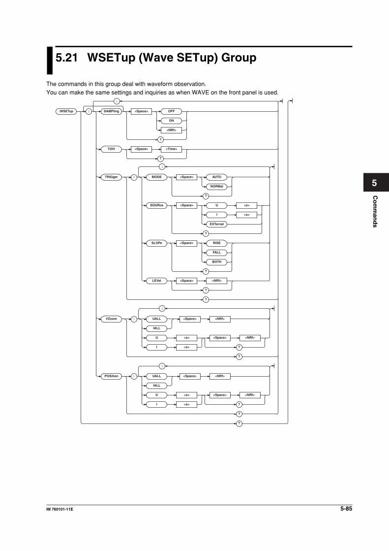
5-85IM 760101-11E
Co
mm
and
s
5
5.21 WSETup (Wave SETup) Group
The commands in this group deal with waveform observation.You can make the same settings and inquiries as when WAVE on the front panel is used.
:WSETup :
;
SAMPling <Space> OFF
ON
<NRf>
?
TDIV <Space> <Time>
?
TRIGg er : MODE <Space> AUTO
NORMal
?
SOURce <Space> U <x>
I <x>
EXTernal
?
SLOPe <Space> RISE
FALL
BOTH
?
LEVel <Space> <NRf>
?
?
VZoom : UALL <Space> <NRf>
IALL
U <x> <Space> <NRf>
?I <x>
?
POSition : UALL <Space> <NRf>
IALL
U <x> <Space> <NRf>
?I <x>
?
?
;
;
;
5-86 IM 760101-11E
:WSETup?
Function Queries all settings related to the waveform
observation.
Syntax :WSETup?
Example :WSETUP? -> :WSETUP:SAMPLING 0;
TDIV 500.0E-06;TRIGGER:MODE AUTO;
SOURCE U1;SLOPE RISE;LEVEL 0.0;:
WSETUP:VZOOM:U1 1.00;U2 1.00;
U3 1.00;U4 1.00;U5 1.00;U6 1.00;
I1 1.00;I2 1.00;I3 1.00;I4 1.00;
I5 1.00;I6 1.00;:WSETUP:POSITION:
U1 0.000;U2 0.000;U3 0.000;
U4 0.000;U5 0.000;U6 0.000;
I1 0.000;I2 0.000;I3 0.000;
I4 0.000;I5 0.000;I6 0.000
:WSETup:POSition?
Function Queries all settings related to the vertical
position (GND position) of the waveform.
Syntax :WSETup:POSition?
Example :WSETUP:POSITION? -> :WSETUP:
POSITION:U1 0.000;U2 0.000;
U3 0.000;U4 0.000;U5 0.000;
U6 0.000;I1 0.000;I2 0.000;
I3 0.000;I4 0.000;I5 0.000;I6 0.000
:WSETup:POSition:{UALL|IALL}
Function Collectively sets the vertical position (level of
the center position) of the waveform
{voltage|current} of all elements.
Syntax :WSETup:POSition:{UALL|
IALL} {<NRf>}
<NRf> = –130.000 to 130.000(%)
Example :WSETUP:POSITION:UALL 0
:WSETup:POSition:{U<x>|I<x>}
Function Sets the vertical position (level of the center
position) of the waveform {voltage|current} of
the element or queries the current setting.
Syntax :WSETup:POSition:{U<x>|
I<x>} {<NRf>}
:WSETup:POSition:{U<x>|I<x>}?
<x> = 1 to 6
<NRf> = –130.000 to 130.000(%)
Example :WSETUP:POSITION:U1 0
:WSETUP:POSITION:U1? -> :WSETUP:
POSITION:U1 0.000
:WSETup[:SAMPling]
Function Turns ON/OFF the waveform sampling or
queries the current setting.
Syntax :WSETup[:SAMPling] {<Boolean>}
:WSETup:SAMPling?
Example :WSETUP:SAMPLING ON
:WSETUP:SAMPLING? -> :WSETUP:
SAMPLING 1
:WSETup:TDIV
Function Sets the Time/div value of the waveform or
queries the current setting.
Syntax :WSETup:TDIV {<Time>}
:WSETup:TDIV?
<Time> = 0.5, 1, 2, 5, 10, 20, 50, 100, 200, 500
(ms)
Example :WSETUP:TDIV 0.5MS
:WSETUP:TDIV? -> :WSETUP:
TDIV 500.0E-06
Description The specifiable Time/div value is up to 1/10 of
the data update rate (:RATE).
:WSETup:TRIGger?
Function Queries all settings related to the trigger.
Syntax :WSETup:TRIGger?
Example :WSETUP:TRIGGER? ->
:WSETUP:TRIGGER:MODE AUTO;
SOURCE U1;SLOPE RISE;LEVEL 0.0
:WSETup:TRIGger:LEVel
Function Sets the trigger level or queries the current
setting.
Syntax :WSETup:TRIGger:LEVel {<NRf>}
:WSETup:TRIGger:LEVel?
<NRf> = –100.0 to 100.0 (%) (The resolution is
0.1(%))
Example :WSETUP:TRIGGER:LEVEL 0
:WSETUP:TRIGGER:LEVEL? -> :WSETUP:
TRIGGER:LEVEL 0.0
Description Set the value in terms of a percentage of the full
scale value displayed on the screen.
:WSETup:TRIGger:MODE
Function Sets the trigger mode or queries the current
setting.
Syntax :WSETup:TRIGger:MODE {AUTO|NORMal}
:WSETup:TRIGger:MODE?
Example :WSETUP:TRIGGER:MODE AUTO
:WSETUP:TRIGGER:MODE? -> :WSETUP:
TRIGGER:MODE AUTO
:WSETup:TRIGger:SLOPe
Function Sets the trigger slope or queries the current
setting.
Syntax :WSETup:TRIGger:SLOPe {RISE|FALL|
BOTH}
:WSETup:TRIGger:SLOPe?
Example :WSETUP:TRIGGER:SLOPE RISE
:WSETUP:TRIGGER:SLOPE? -> :WSETUP:
TRIGGER:SLOPE RISE
5.21 WSETup (Wave SETup) Group
5-87IM 760101-11E
Co
mm
and
s
5
:WSETup:TRIGger:SOURce
Function Sets the trigger source or queries the current
setting.
Syntax :WSETup:TRIGger:SOURce {U<x>|I<x>|
EXTernal}
:WSETup:TRIGger:SOURce?
<x> = 1 to 6 (element)
EXTernal = External trigger input (Ext Clk)
Example :WSETUP:TRIGGER:SOURCE U1
:WSETUP:TRIGGER:SOURCE? -> :WSETUP:
TRIGGER:SOURCE U1
:WSETup:VZoom?
Function Queries all settings related to the vertical zoom
factor of the waveform.
Syntax :WSETup:VZoom?
Example :WSETUP:VZOOM? -> :WSETUP:VZOOM:
U1 1.00;U2 1.00;U3 1.00;U4 1.00;
U5 1.00;U6 1.00;I1 1.00;I2 1.00;
I3 1.00;I4 1.00;I5 1.00;I6 1.00
:WSETup:VZoom:{UALL|IALL}
Function Collectively sets the vertical zoom factor of the
waveform {voltage|current} of all elements.
Syntax :WSETup:VZoom:{UALL|IALL} {<NRf>}
<NRf> = 0.1 to 100 (see the WT1600 User’s
Manual)
Example :WSETUP:VZOOM:UALL 1
:WSETup:VZoom:{U<x>|I<x>}
Function Sets the vertical zoom factor of the waveform
{voltage|current} of the element or queries the
current setting.
Syntax :WSETup:VZoom:{U<x>|I<x>} {<NRf>}
:WSETup:VZoom:{U<x>|I<x>}?
<x> = 1 to 6
<NRf> = 0.1 to 100 (see the WT1600 User’s
Manual)
Example :WSETUP:VZOOM:U1 1
:WSETUP:VZOOM:U1? -> :WSETUP:VZOOM:
U1 1.00
5.21 WSETup (Wave SETup) Group
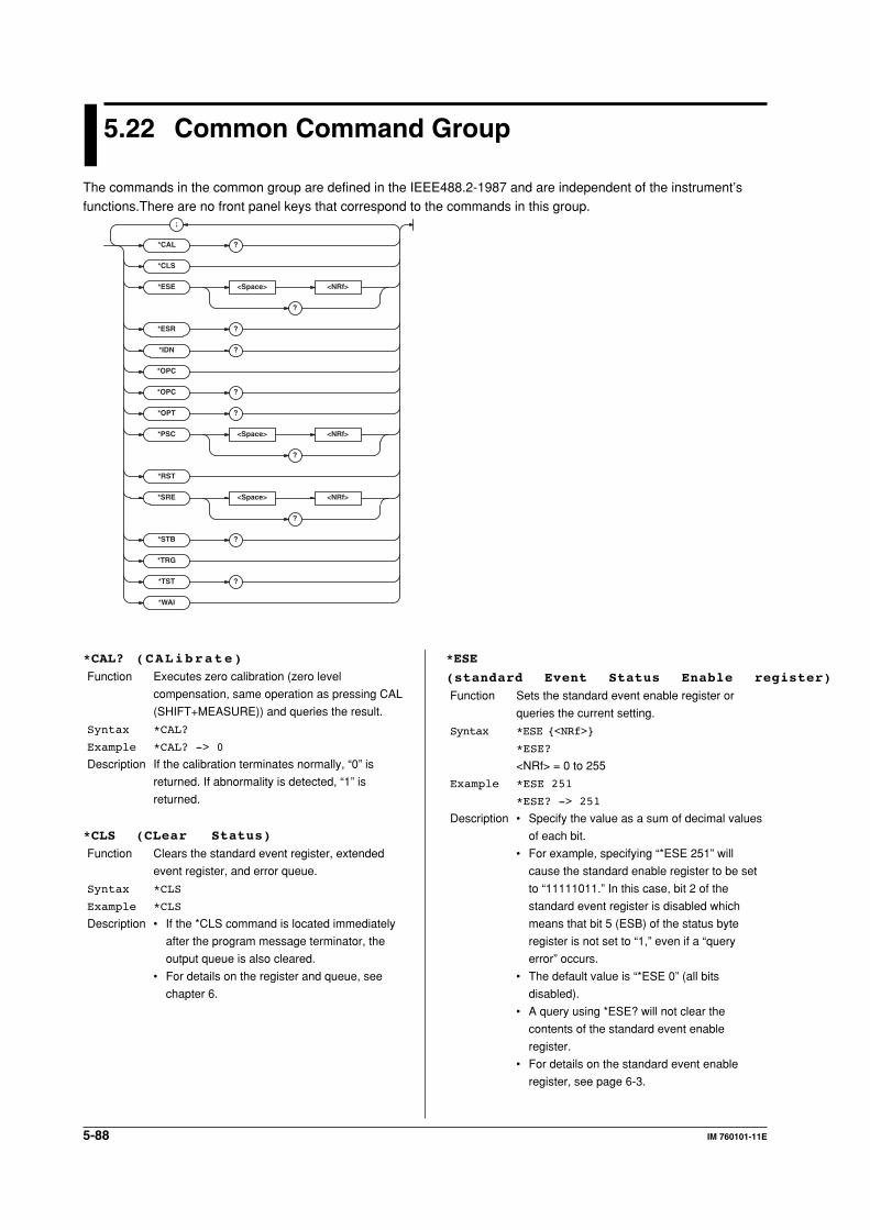
5-88 IM 760101-11E
5.22 Common Command Group
The commands in the common group are defined in the IEEE488.2-1987 and are independent of the instrument’sfunctions.There are no front panel keys that correspond to the commands in this group.
*CAL
*CLS
*ESE <Space> <NRf>
?
*ESR ?
?
*IDN ?
*OPC
*OPC ?
*OPT ?
*PSC <Space> <NRf>
?
*RST
*SRE <Space> <NRf>
?
*STB ?
*TRG
*TST ?
*WAI
;
*ESE
(standard Event Status Enable register)
Function Sets the standard event enable register or
queries the current setting.
Syntax *ESE {<NRf>}
*ESE?
<NRf> = 0 to 255
Example *ESE 251
*ESE? -> 251
Description • Specify the value as a sum of decimal values
of each bit.
• For example, specifying “*ESE 251” will
cause the standard enable register to be set
to “11111011.” In this case, bit 2 of the
standard event register is disabled which
means that bit 5 (ESB) of the status byte
register is not set to “1,” even if a “query
error” occurs.
• The default value is “*ESE 0” (all bits
disabled).
• A query using *ESE? will not clear the
contents of the standard event enable
register.
• For details on the standard event enable
register, see page 6-3.
*CAL? (CALibrate)
Function Executes zero calibration (zero level
compensation, same operation as pressing CAL
(SHIFT+MEASURE)) and queries the result.
Syntax *CAL?
Example *CAL? -> 0
Description If the calibration terminates normally, “0” is
returned. If abnormality is detected, “1” is
returned.
*CLS (CLear Status)
Function Clears the standard event register, extended
event register, and error queue.
Syntax *CLS
Example *CLS
Description • If the *CLS command is located immediately
after the program message terminator, the
output queue is also cleared.
• For details on the register and queue, see
chapter 6.
5-89IM 760101-11E
Co
mm
and
s
5
*ESR? (standard Event Status Register)
Function Queries the standard event register and clears
the register.
Syntax *ESR?
Example *ESR? -> 32
Description • A sum of decimal values of each bit is
returned.
• You can check what type of events occurred
when an SRQ is generated.
• For example, if a value of “32” is returned,
this indicates that the standard event register
is set to “00100000.” In this case, you can
see that the SRQ occurred due to a
“command syntax error.”
• A query using *ESR? will clear the contents of
the standard event register.
• For details on the standard event register,
see page 6-3.
*IDN? ( I D e N t i f y )
Function Queries the instrument model.
Syntax *IDN?
Example *IDN? -> YOKOGAWA,760101-60,0,F1.01
Description The information is returned in the following form:
<Manufacturer>,<Model>,<Serial
No.>,<Firmware version>In actuality, <Serial
No.> is not returned (always 0).
*OPC (OPeration Complete)
Function Sets a “1” to bit 0 (OPC bit) of the standard
event register bit upon the completion of the
specified overlap command.
Syntax *OPC
Example *OPC
Description • For the description regarding how to
synchronize the program using *OPC, see
page 4-8.
• The “COMMunicate:OPSE” command is used
to specify the overlap command.
• If *OPC is not the last command of the
message, the operation is not guaranteed.
*OPC? (OPeration Complete)
Function If the specified overlap command is completed,
ASCII code “1” is returned.
Syntax *OPC?
Example *OPC? -> 1
Description • For the description regarding how to
synchronize the program using *OPC, see
page 4-8.
• The “COMMunicate:OPSE” command is used
to specify the overlap command.
• If *OPC? is not the last command of the
message, the operation is not guaranteed.
*OPT? (OPTion)
Function Queries the installed options.
Syntax *OPT?
Example *OPT? -> B5,DA,MTR,C10
Description • The presence or absence of the built-in
printer (/B5), DA output (/DA), motor
evaluation function (/MTR), SCSI interface (/
C7), or Ethernet+SCSI+built-in HDD (/C10) is
returned.
• If none of the options is installed, an ASCII
code “0” is returned.
• The “*OPT?” query must be the last query of
the program message. An error occurs if
there is a query after this query.
*PSC (Power-on Status Clear)
Function Sets whether or not to clear the registers below
at power up or queries the current setting. The
register is cleared when the value rounded to an
integer is a non-zero value.
• Standard event enable register
• Extended event enable register
• Transition filter
Syntax *PSC {<NRf>}
*PSC?
<NRf> = 0(not clear), non-zero (clear)
Example *PSC 1
*PSC? -> 1
Description For details on the registers, see chapter 6.
*RST (ReSeT)
Function Initializes the settings.
Syntax *RST
Example *RST
Description • Also clears *OPC and *OPC? commands that
have been sent earlier.
• All settings except communication settings
are reset to factory default values.
5.22 Common Command Group
5-90 IM 760101-11E
*SRE (Service Request Enable register)
Function Sets the service request enable register or
queries the current setting.
Syntax *SRE <NRf>
*SRE?
<NRf> = 0 to 255
Example *SRE 239
*SRE? -> 175 (since the bit 6 (MSS) setting is
ignored)
Description • Specify the value as a sum of decimal values
of each bit.
• For example, specifying “*SRE 239” will
cause the service request enable register to
be set to “11101111.” In this case, bit 4 of the
service request enable register is disabled
which means that bit 4 (MAV) of the status
byte register is not set to “1,” even if “the
output queue is not empty.”
• Bit 6 (MSS) of the status byte register is the
MSS bit itself, and therefore, it is ignored.
• The default value is “*SRE 0” (all bits
disabled).
• A query using *SRE? will not clear the
contents of the service request enable
register.
• For details on the service request enable
register, see page 6-2.
*STB? (STatus Byte)
Function Queries the status byte register.
Syntax *STB?
Example *STB? -> 4
Description • The sum of the bits is returned as a decimal
value.
• Since the register is read without executing
serial polling, bit 6 is a MSS bit not RQS.
• For example, if a value of “4” is returned, this
indicates that the status byte register is set to
“00000100.” In this case, you can see that
“the error queue is not empty” (an error
occurred).
• A query using *STB? will not clear the
contents of the status byte register.
• For details on the status byte register, see
page 6-2.
*TRG (TRiGger)
Function Executes the same operation as when SINGLE
(SHIFT+HOLD) is pressed.
Syntax *TRG
Example *TRG
Description The multi-line message GET (Group Execute
Trigger) also performs the same operation as
this command.
*TST? (TeST)
Function Performs a self-test and queries the result.
Syntax *TST?
Example *TST? -> 0
Description • The self-test involves internal memory tests.
• “0” is returned if the self-test is successful, “1”
if it is not.
*WAI (WAIt)
Function Holds the subsequent command until the
completion of the specified overlap operation.
Syntax *WAI
Example *WAI
Description • For the description regarding how to
synchronize the program using *WAI, see
page 4-7.
• The “COMMunicate:OPSE” command is used
to specify the overlap command.
5.22 Common Command Group
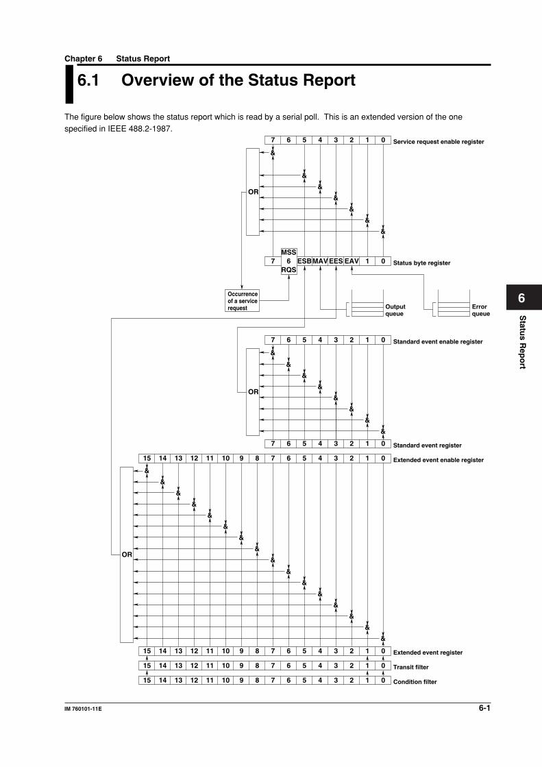
6-1IM 760101-11E
Statu
s Rep
ort
6
6.1 Overview of the Status Report
The figure below shows the status report which is read by a serial poll. This is an extended version of the onespecified in IEEE 488.2-1987.
15 14 13 12 11 10 9 8 7 6 5 4 3 2 1 0
15 14 13 12 11 10 9 8 7 6 5 4 3 2 1 0
15 14 13 12 11 10 9 8 7 6 5 4 3 2 1 0
Condition filter
Transit filter
Extended event register
&
15 14 13 12 11 10 9 8 7 6 5 4 3 2 1 0 Extended event enable register
&
&
&
&
&
&
&
&
&
&
&
&
&
&
&
7 6 5 4 3 2 1 0 Standard event register
&
&
&
&
&
&
&
&
7 6 5 4 3 2 1 0 Standard event enable register
OR
OR
7 6 ESBMAVEES EAV 1 0 Status byte register
MSS
RQS
Output queue
Error queue
Occurrence of a service request
&
&
&
&
&
&
&
7 6 5 4 3 2 1 0 Service request enable register
OR
Chapter 6 Status Report
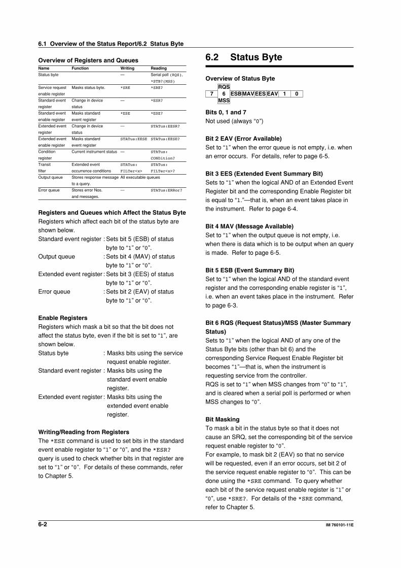
6-2 IM 760101-11E
Overview of Registers and QueuesName Function Writing Reading
Status byte — Serial poll (RQS),
*STB?(MSS)
Service request Masks status byte. *SRE *SRE?
enable register
Standard event Change in device — *ESR?
register status
Standard event Masks standard *ESE *ESE?
enable register event register
Extended event Change in device — STATus:EESR?
register status
Extended event Masks standard STATus:EESE STATus:EESE?
enable register event register
Condition Current instrument status — STATus:
register CONDition?
Transit Extended event STATus: STATus:
filter occurrence conditions FILTer<x> FILTer<x>?
Output queue Stores response message All executable queues
to a query.
Error queue Stores error Nos. — STATus:ERRor?
and messages.
Registers and Queues which Affect the Status ByteRegisters which affect each bit of the status byte areshown below.Standard event register : Sets bit 5 (ESB) of status
byte to “1” or “0”.Output queue : Sets bit 4 (MAV) of status
byte to “1” or “0”.
Extended event register : Sets bit 3 (EES) of statusbyte to “1” or “0”.
Error queue : Sets bit 2 (EAV) of status
byte to “1” or “0”.
Enable RegistersRegisters which mask a bit so that the bit does notaffect the status byte, even if the bit is set to “1”, areshown below.
Status byte : Masks bits using the servicerequest enable register.
Standard event register : Masks bits using the
standard event enableregister.
Extended event register : Masks bits using the
extended event enableregister.
Writing/Reading from RegistersThe *ESE command is used to set bits in the standardevent enable register to “1” or “0”, and the *ESR?
query is used to check whether bits in that register areset to “1” or “0”. For details of these commands, referto Chapter 5.
6.2 Status Byte
Overview of Status Byte
7 6 ESBMAVEES EAV 1 0RQS
MSS
Bits 0, 1 and 7Not used (always “0”)
Bit 2 EAV (Error Available)Set to “1” when the error queue is not empty, i.e. whenan error occurs. For details, refer to page 6-5.
Bit 3 EES (Extended Event Summary Bit)Sets to “1” when the logical AND of an Extended Event
Register bit and the corresponding Enable Register bitis equal to “1.”—that is, when an event takes place inthe instrument. Refer to page 6-4.
Bit 4 MAV (Message Available)Set to “1” when the output queue is not empty, i.e.
when there is data which is to be output when an queryis made. Refer to page 6-5.
Bit 5 ESB (Event Summary Bit)Set to “1” when the logical AND of the standard eventregister and the corresponding enable register is “1”,i.e. when an event takes place in the instrument. Refer
to page 6-3.
Bit 6 RQS (Request Status)/MSS (Master SummaryStatus)Sets to “1” when the logical AND of any one of theStatus Byte bits (other than bit 6) and the
corresponding Service Request Enable Register bitbecomes “1”—that is, when the instrument isrequesting service from the controller.
RQS is set to “1” when MSS changes from “0” to “1”,and is cleared when a serial poll is performed or whenMSS changes to “0”.
Bit MaskingTo mask a bit in the status byte so that it does not
cause an SRQ, set the corresponding bit of the servicerequest enable register to “0”.For example, to mask bit 2 (EAV) so that no service
will be requested, even if an error occurs, set bit 2 ofthe service request enable register to “0”. This can bedone using the *SRE command. To query whether
each bit of the service request enable register is “1” or“0”, use *SRE?. For details of the *SRE command,refer to Chapter 5.
6.1 Overview of the Status Report/6.2 Status Byte
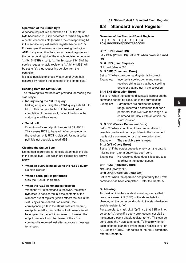
6-3IM 760101-11E
Statu
s Rep
ort
6
Operation of the Status ByteA service request is issued when bit 6 of the status
byte becomes “1”. Bit 6 becomes “1” when any of theother bits becomes “1” (or when the corresponding bitin the service request enable register becomes “1”).
For example, if an event occurs causing the logicalAND of any one bit in the standard event register andthe corresponding bit of the enable register to become
“1,” bit 5 (ESB) is set to “1.” In this case, if bit 5 of theservice request enable register is “1”, bit 6 (MSS) willbe set to “1”, thus requesting service from the
controller.It is also possible to check what type of event hasoccurred by reading the contents of the status byte.
Reading from the Status ByteThe following two methods are provided for reading the
status byte.• Inquiry using the *STB? query
Making an query using the *STB? query sets bit 6 to
MSS. This causes the MSS to be read. Aftercompletion of the read-out, none of the bits in thestatus byte will be cleared.
• Serial pollExecution of a serial poll changes bit 6 to RQS.This causes RQS to be read. After completion of
the read-out, only RQS is cleared. Using a serialpoll, it is not possible to read MSS.
Clearing the Status ByteNo method is provided for forcibly clearing all the bitsin the status byte. Bits which are cleared are shown
below.
• When an query is made using the *STB? queryNo bit is cleared.
• When a serial poll is performedOnly the RQS bit is cleared.
• When the *CLS command is receivedWhen the *CLS command is received, the statusbyte itself is not cleared, but the contents of thestandard event register (which affects the bits in the
status byte) are cleared. As a result, thecorresponding bits in the status byte are cleared,except bit 4 (MAV), since the output queue cannot
be emptied by the *CLS command. However, theoutput queue will also be cleared if the *CLScommand is received just after a program message
terminator.
6.3 Standard Event Register
Overview of the Standard Event Register
URQ6
PON7 5 4 3 2 1 0
CMEEXE DDEQYERQCOPC
Bit 7 PON (Power ON)Bit 7 PON (Power ON) Set to “1” when power is turnedON
Bit 6 URQ (User Request)Not used (always “0”)Bit 5 CME (Command Error)Set to “1” when the command syntax is incorrect.Examples: Incorrectly spelled command name;
received string data that have spelling
errors or that are not in the selection.Bit 4 EXE (Execution Error)Set to “1” when the command syntax is correct but the
command cannot be executed in the current state.Examples: Parameters are outside the setting
range: received a command that has a
parameter that is outside the range or acommand that deals with an option thatis not installed.
Bit 3 DDE (Device Dependent Error)Set to “1” when execution of the command is notpossible due to an internal problem in the instrumentthat is not a command error or an execution error.
Example: The circuit breaker is reset.Bit 2 QYE (Query Error)Set to “1” if the output queue is empty or if the data is
missing even after a query has been sent.Examples: No response data; data is lost due to an
overflow in the output queue.
Bit 1 RQC (Request Control)Not used (always “0”)Bit 0 OPC (Operation Complete)Set to “1” when the operation designated by the *OPCcommand has been completed. Refer to Chapter 5.
Bit MaskingTo mask a bit in the standard event register so that itdoes not cause bit 5 (ESB) of the status byte to
change, set the corresponding bit in the standard eventenable register to “0”.For example, to mask bit 2 (QYE) so that ESB will not
be set to “1”, even if a query error occurs, set bit 2 ofthe standard event enable register to “0”. This can bedone using the *ESE command. To inquire whether
each bit of the standard event enable register is “1” or“0”, use the *ESE?. For details of the *ESE command,refer to Chapter 5.
6.2 Status Byte/6.3 Standard Event Register
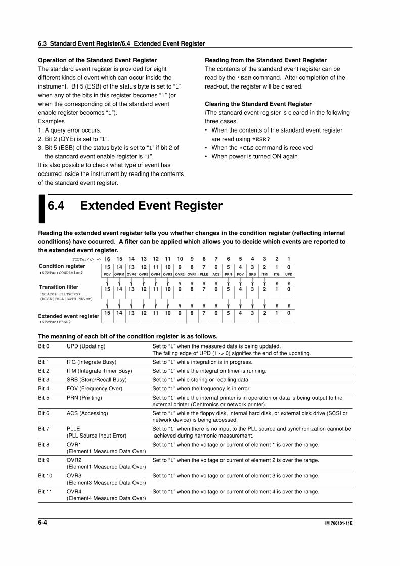
6-4 IM 760101-11E
Operation of the Standard Event RegisterThe standard event register is provided for eight
different kinds of event which can occur inside theinstrument. Bit 5 (ESB) of the status byte is set to “1”when any of the bits in this register becomes “1” (or
when the corresponding bit of the standard eventenable register becomes “1”).Examples
1. A query error occurs.2. Bit 2 (QYE) is set to “1”.3. Bit 5 (ESB) of the status byte is set to “1” if bit 2 of
the standard event enable register is “1”.It is also possible to check what type of event hasoccurred inside the instrument by reading the contents
of the standard event register.
Reading from the Standard Event RegisterThe contents of the standard event register can be
read by the *ESR command. After completion of theread-out, the register will be cleared.
Clearing the Standard Event RegisterïThe standard event register is cleared in the followingthree cases.
• When the contents of the standard event registerare read using *ESR?
• When the *CLS command is received
• When power is turned ON again
6.3 Standard Event Register/6.4 Extended Event Register
6.4 Extended Event Register
Reading the extended event register tells you whether changes in the condition register (reflecting internalconditions) have occurred. A filter can be applied which allows you to decide which events are reported tothe extended event register.
ACS
6PLLE
7 5 4 3 2 1 0PRN FOV SRB ITM ITG UPDOVR1
8OVR2
9OVR3
10OVR4
11OVR5
12OVR6
13OVRM
14POV
15
67 5 4 3 2 1 089101112131415
Condition register:STATus:CONDition?
Transition filter
01415Extended event register
167 5 4 38910111213 2
67 5 4 3 2 18910111213141516
:STATus:FILTer<x>{RISE|FALL|BOTH|NEVer}
:STATus:EESR?
FILTer<x> ->
The meaning of each bit of the condition register is as follows.
Bit 0 UPD (Updating) Set to “1” when the measured data is being updated.The falling edge of UPD (1 -> 0) signifies the end of the updating.
Bit 1 ITG (Integrate Busy) Set to “1” while integration is in progress.
Bit 2 ITM (Integrate Timer Busy) Set to “1” while the integration timer is running.
Bit 3 SRB (Store/Recall Busy) Set to “1” while storing or recalling data.
Bit 4 FOV (Frequency Over) Set to “1” when the frequency is in error.
Bit 5 PRN (Printing) Set to “1” while the internal printer is in operation or data is being output to theexternal printer (Centronics or network printer).
Bit 6 ACS (Accessing) Set to “1” while the floppy disk, internal hard disk, or external disk drive (SCSI ornetwork device) is being accessed.
Bit 7 PLLE Set to “1” when there is no input to the PLL source and synchronization cannot be(PLL Source Input Error) achieved during harmonic measurement.
Bit 8 OVR1 Set to “1” when the voltage or current of element 1 is over the range.(Element1 Measured Data Over)
Bit 9 OVR2 Set to “1” when the voltage or current of element 2 is over the range.(Element1 Measured Data Over)
Bit 10 OVR3 Set to “1” when the voltage or current of element 3 is over the range.(Element3 Measured Data Over)
Bit 11 OVR4 Set to “1” when the voltage or current of element 4 is over the range.(Element4 Measured Data Over)
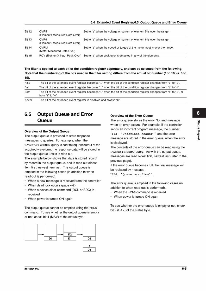
6-5IM 760101-11E
Statu
s Rep
ort
6
Bit 12 OVR5 Set to “1” when the voltage or current of element 5 is over the range.(Element4 Measured Data Over)
Bit 13 OVR6 Set to “1” when the voltage or current of element 6 is over the range.(Element6 Measured Data Over)
Bit 14 OVRM Set to “1” when the speed or torque of the motor input is over the range.(Motor Measured Data Over)
Bit 15 POV (ElementX Input Peak Over) Set to “1” when peak over is detected in any of the elements.
The filter is applied to each bit of the condition register seperately, and can be selected from the following.Note that the numbering of the bits used in the filter setting differs from the actual bit number (1 to 16 vs. 0 to15).
Rise The bit of the extended event register becomes “1” when the bit of the condition register changes from “0” to “1”.
Fall The bit of the extended event register becomes “1” when the bit of the condition register changes from “1” to “0”.
Both The bit of the extended event register becomes “1” when the bit of the condition register changes from “0” to “1”, orfrom “1” to “0”.
Never The bit of the extended event register is disabled and always “0”.
6.5 Output Queue and ErrorQueue
Overview of the Output QueueThe output queue is provided to store responsemessages to queries. For example, when theWAVeform:SEND? query is sent to request output of the
acquired waveform, the response data will be stored inthe output queue until it is read out.The example below shows that data is stored record
by record in the output queue, and is read out oldestitem first, newest item last. The output queue isemptied in the following cases (in addition to when
read-out is performed).• When a new message is received from the controller• When dead lock occurs (page 4-2)
• When a device clear command (DCL or SDC) isreceived
• When power is turned ON again
The output queue cannot be emptied using the *CLScommand. To see whether the output queue is empty
or not, check bit 4 (MAV) of the status byte.
D1D2D1 D2
D1
Overview of the Error QueueThe error queue stores the error No. and messagewhen an error occurs. For example, if the controllersends an incorrect program message, the number,
“113, "Undefined header"”, and the errormessage are stored in the error queue, when the erroris displayed.
The contents of the error queue can be read using theSTATus:ERRor? query. As with the output queue,messages are read oldest first, newest last (refer to the
previous page).If the error queue becomes full, the final message willbe replaced by message
“350, "Queue overflow"”.
The error queue is emptied in the following cases (in
addition to when read-out is performed).• When the *CLS command is received• When power is turned ON again
To see whether the error queue is empty or not, checkbit 2 (EAV) of the status byte.
6.4 Extended Event Register/6.5 Output Queue and Error Queue
Sam
ple P
rog
ram
7-1IM 760101-11E
7
7.1 Before Programming
EnvironmentTarget model: IBM-AT compatible PC
Target language: Visual Basic Ver5.0 Professional Edition or later.GP-IB board: AT-GP-IB/TNT IEEE-488.2 by National Instruments.
Settings on Visual BasicStandard modules used: Niglobal.bas
Vbib-32.bas
Setting the WT1600GP-IBThe sample programs given in this chapter use a GP-IB address of 1 for the WT1600.Set the GP-IB address to 1 according to the procedures on page 1-5.
Chapter 7 Sample Program
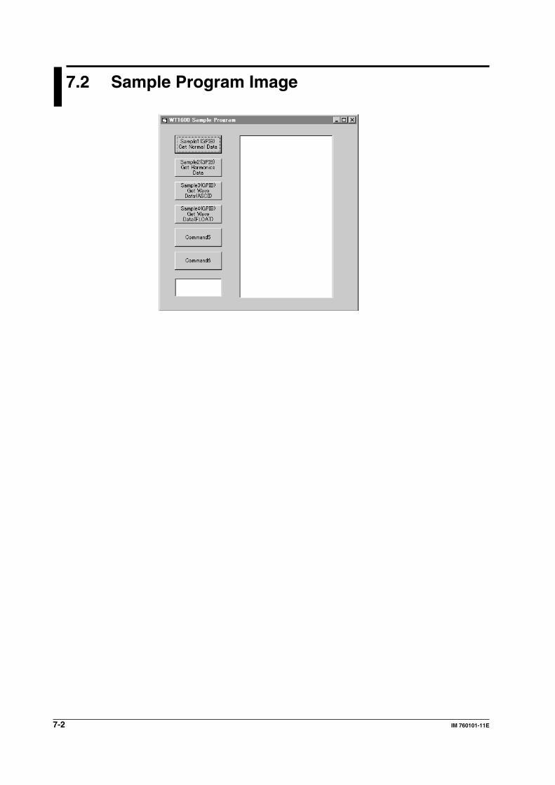
7-2 IM 760101-11E
7.2 Sample Program Image
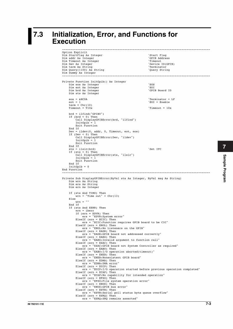
Sam
ple P
rog
ram
7-3IM 760101-11E
7
7.3 Initialization, Error, and Functions forExecution
----------------------------------------------------------------------------------------Option ExplicitDim StartFlag As Integer 'Start FlagDim addr As Integer 'GPIB AddressDim Timeout As Integer 'TimeoutDim Dev As Integer 'Device ID(GPIB)Dim term As String 'TerminatorDim Query(1100) As String 'Query StringDim Dummy As Integer----------------------------------------------------------------------------------------
Private Function InitGpib() As Integer Dim eos As Integer 'EOS Dim eot As Integer 'EOI Dim brd As Integer 'GPIB Board ID Dim sts As Integer
eos = &HC0A 'Terminator = LF eot = 1 'EOI = Enable term = Chr(10) Timeout = T10s 'Timeout = 10s
brd = ilfind("GPIB0") If (brd < 0) Then Call DisplayGPIBError(brd, "ilfind") InitGpib = 1 Exit Function End If Dev = ildev(0, addr, 0, Timeout, eot, eos) If (Dev < 0) Then Call DisplayGPIBError(Dev, "ildev") InitGpib = 1 Exit Function End If sts = ilsic(brd) 'Set IFC If (sts < 0) Then Call DisplayGPIBError(sts, "ilsic") InitGpib = 1 Exit Function End If InitGpib = 0End Function----------------------------------------------------------------------------------------
Private Sub DisplayGPIBError(ByVal sts As Integer, ByVal msg As String) Dim wrn As String Dim ers As String Dim ern As Integer
If (sts And TIMO) Then wrn = "Time out" + Chr(13) Else wrn = "" End If If (sts And EERR) Then ern = iberr If (ern = EDVR) Then ers = "EDVR:System error" ElseIf (ern = ECIC) Then ers = "ECIC:Function requires GPIB board to be CIC" ElseIf (ern = ENOL) Then ers = "ENOL:No Listeners on the GPIB" ElseIf (ern = EADR) Then ers = "EADR:GPIB board not addressed correctly" ElseIf (ern = EARG) Then ers = "EARG:Invalid argument to function call" ElseIf (ern = ESAC) Then ers = "ESAC:GPIB board not System Controller as required" ElseIf (ern = EABO) Then ers = "EABO:I/O operation aborted(timeout)" ElseIf (ern = ENEB) Then ers = "ENEB:Nonexistent GPIB board" ElseIf (ern = EDMA) Then ers = "EDMA:DMA error" ElseIf (ern = EOIP) Then ers = "EOIP:I/O operation started before previous operation completed" ElseIf (ern = ECAP) Then ers = "ECAP:No capability for intended operation" ElseIf (ern = EFSO) Then ers = "EFSO:File system operation error" ElseIf (ern = EBUS) Then ers = "EBUS:GPIB bus error" ElseIf (ern = ESTB) Then ers = "ESTB:Serial poll status byte queue overflow" ElseIf (ern = ESRQ) Then ers = "ESRQ:SRQ remains asserted"
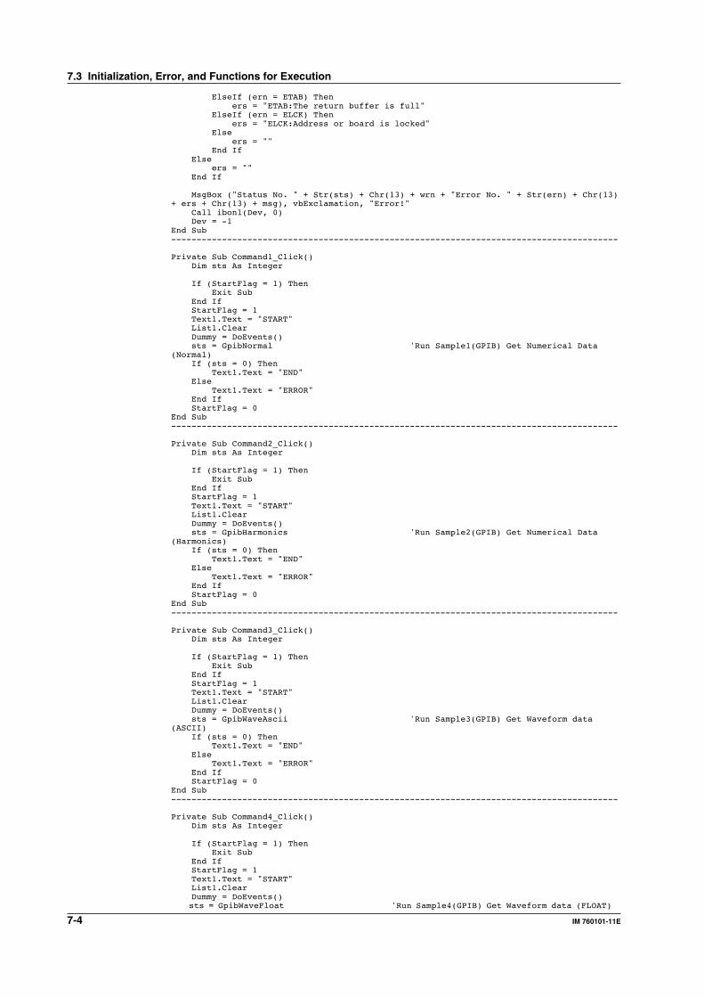
7-4 IM 760101-11E
ElseIf (ern = ETAB) Then ers = "ETAB:The return buffer is full" ElseIf (ern = ELCK) Then ers = "ELCK:Address or board is locked" Else ers = "" End If Else ers = "" End If
MsgBox ("Status No. " + Str(sts) + Chr(13) + wrn + "Error No. " + Str(ern) + Chr(13)+ ers + Chr(13) + msg), vbExclamation, "Error!" Call ibonl(Dev, 0) Dev = -1End Sub----------------------------------------------------------------------------------------
Private Sub Command1_Click() Dim sts As Integer
If (StartFlag = 1) Then Exit Sub End If StartFlag = 1 Text1.Text = "START" List1.Clear Dummy = DoEvents() sts = GpibNormal 'Run Sample1(GPIB) Get Numerical Data(Normal) If (sts = 0) Then Text1.Text = "END" Else Text1.Text = "ERROR" End If StartFlag = 0End Sub----------------------------------------------------------------------------------------
Private Sub Command2_Click() Dim sts As Integer
If (StartFlag = 1) Then Exit Sub End If StartFlag = 1 Text1.Text = "START" List1.Clear Dummy = DoEvents() sts = GpibHarmonics 'Run Sample2(GPIB) Get Numerical Data(Harmonics) If (sts = 0) Then Text1.Text = "END" Else Text1.Text = "ERROR" End If StartFlag = 0End Sub----------------------------------------------------------------------------------------
Private Sub Command3_Click() Dim sts As Integer
If (StartFlag = 1) Then Exit Sub End If StartFlag = 1 Text1.Text = "START" List1.Clear Dummy = DoEvents() sts = GpibWaveAscii 'Run Sample3(GPIB) Get Waveform data(ASCII) If (sts = 0) Then Text1.Text = "END" Else Text1.Text = "ERROR" End If StartFlag = 0End Sub----------------------------------------------------------------------------------------
Private Sub Command4_Click() Dim sts As Integer
If (StartFlag = 1) Then Exit Sub End If StartFlag = 1 Text1.Text = "START" List1.Clear Dummy = DoEvents() sts = GpibWaveFloat 'Run Sample4(GPIB) Get Waveform data (FLOAT)
7.3 Initialization, Error, and Functions for Execution
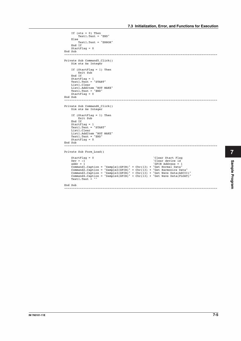
Sam
ple P
rog
ram
7-5IM 760101-11E
7
If (sts = 0) Then Text1.Text = "END" Else Text1.Text = "ERROR" End If StartFlag = 0End Sub----------------------------------------------------------------------------------------
Private Sub Command5_Click() Dim sts As Integer
If (StartFlag = 1) Then Exit Sub End If StartFlag = 1 Text1.Text = "START" List1.Clear List1.AddItem "NOT MAKE" Text1.Text = "END" StartFlag = 0End Sub----------------------------------------------------------------------------------------
Private Sub Command6_Click() Dim sts As Integer
If (StartFlag = 1) Then Exit Sub End If StartFlag = 1 Text1.Text = "START" List1.Clear List1.AddItem "NOT MAKE" Text1.Text = "END" StartFlag = 0End Sub----------------------------------------------------------------------------------------
Private Sub Form_Load()
StartFlag = 0 'Clear Start Flag Dev = -1 'Clear device id addr = 1 'GPIB Address = 1 Command1.Caption = "Sample1(GPIB)" + Chr(13) + "Get Normal Data" Command2.Caption = "Sample2(GPIB)" + Chr(13) + "Get Harmonics Data" Command3.Caption = "Sample3(GPIB)" + Chr(13) + "Get Wave Data(ASCII)" Command4.Caption = "Sample4(GPIB)" + Chr(13) + "Get Wave Data(FLOAT)" Text1.Text = ""
End Sub----------------------------------------------------------------------------------------
7.3 Initialization, Error, and Functions for Execution
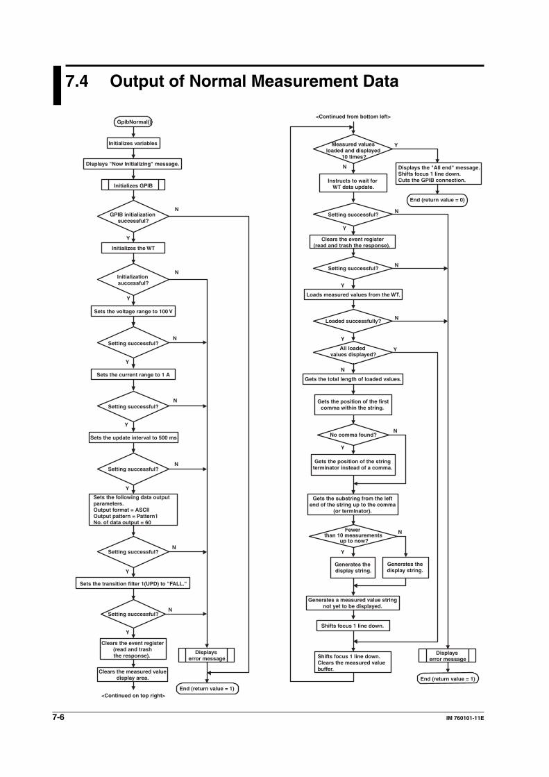
7-6 IM 760101-11E
7.4 Output of Normal Measurement Data
GpibNormal()
Y
N
Y
N
Y
N
Y
N
Y
N
Y
N
Y
N
Y
N
Y
N
Y
N
Y
N
Y
N
N
Y
Y
N
End (return value = 0)
Initializes variables
Displays "Now Initializing" message.
Initializes GPIB
GPIB initialization successful?
Initializes the WT
Initialization successful?
Sets the voltage range to 100 V
Setting successful?
Sets the current range to 1 A
Setting successful?
Sets the update interval to 500 ms
Setting successful?
Sets the following data output parameters.Output format = ASCIIOutput pattern = Pattern1No. of data output = 60
Setting successful?
Sets the transition filter 1(UPD) to "FALL."
Setting successful?
Clears the event register (read and trash the response).
Clears the measured value display area.
<Continued on top right>
Displays error message
End (return value = 1)
Displays error message
End (return value = 1)
<Continued from bottom left>
Measured values loaded and displayed
10 times?
Instructs to wait for WT data update.
Setting successful?
Clears the event register (read and trash the response).
Setting successful?
Loads measured values from the WT.
Loaded successfully?
All loaded values displayed?
Gets the total length of loaded values.
Gets the position of the first comma within the string.
No comma found?
Gets the position of the string terminator instead of a comma.
Gets the substring from the left end of the string up to the comma
(or terminator).
Fewer than 10 measurements
up to now?
Generates the display string.
Generates the display string.
Generates a measured value string not yet to be displayed.
Shifts focus 1 line down.
Shifts focus 1 line down. Clears the measured value buffer.
Displays the "All end" message. Shifts focus 1 line down. Cuts the GPIB connection.
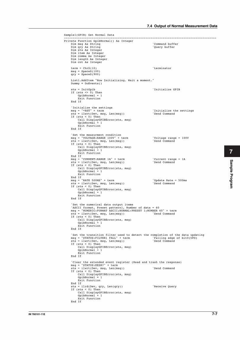
Sam
ple P
rog
ram
7-7IM 760101-11E
7
Sample1(GPIB) Get Normal Data----------------------------------------------------------------------------------------Private Function GpibNormal() As Integer Dim msg As String 'Command buffer Dim qry As String 'Query buffer Dim sts As Integer Dim item As Integer Dim comma As Integer Dim length As Integer Dim cnt As Integer
term = Chr$(10) 'terminator msg = Space$(100) qry = Space$(900)
List1.AddItem "Now Initializing. Wait a moment." Dummy = DoEvents()
sts = InitGpib 'Initialize GPIB If (sts <> 0) Then GpibNormal = 1 Exit Function End If
'Initialize the settings msg = "*RST" + term 'Initialize the settings sts = ilwrt(Dev, msg, Len(msg)) 'Send Command If (sts < 0) Then Call DisplayGPIBError(sts, msg) GpibNormal = 1 Exit Function End If
'Set the measurment condition msg = "VOLTAGE:RANGE 100V" + term 'Voltage range = 100V sts = ilwrt(Dev, msg, Len(msg)) 'Send Command If (sts < 0) Then Call DisplayGPIBError(sts, msg) GpibNormal = 1 Exit Function End If msg = "CURRENT:RANGE 1A" + term 'Current range = 1A sts = ilwrt(Dev, msg, Len(msg)) 'Send Command If (sts < 0) Then Call DisplayGPIBError(sts, msg) GpibNormal = 1 Exit Function End If msg = "RATE 500MS" + term 'Update Rate = 500ms sts = ilwrt(Dev, msg, Len(msg)) 'Send Command If (sts < 0) Then Call DisplayGPIBError(sts, msg) GpibNormal = 1 Exit Function End If
'Set the numerical data output items 'ASCII format, Preset pattern1, Number of data = 60 msg = "NUMERIC:FORMAT ASCII;NORMAL:PRESET 1;NUMBER 60" + term sts = ilwrt(Dev, msg, Len(msg)) 'Send Command If (sts < 0) Then Call DisplayGPIBError(sts, msg) GpibNormal = 1 Exit Function End If
'Set the transition filter used to detect the completion of the data updating msg = "STATUS:FILTER1 FALL" + term 'Falling edge of bit0(UPD) sts = ilwrt(Dev, msg, Len(msg)) 'Send Command If (sts < 0) Then Call DisplayGPIBError(sts, msg) GpibNormal = 1 Exit Function End If
'Clear the extended event register (Read and trash the response) msg = "STATUS:EESR?" + term sts = ilwrt(Dev, msg, Len(msg)) 'Send Command If (sts < 0) Then Call DisplayGPIBError(sts, msg) GpibNormal = 1 Exit Function End If sts = ilrd(Dev, qry, Len(qry)) 'Receive Query If (sts < 0) Then Call DisplayGPIBError(sts, msg) GpibNormal = 1 Exit Function End If
7.4 Output of Normal Measurement Data
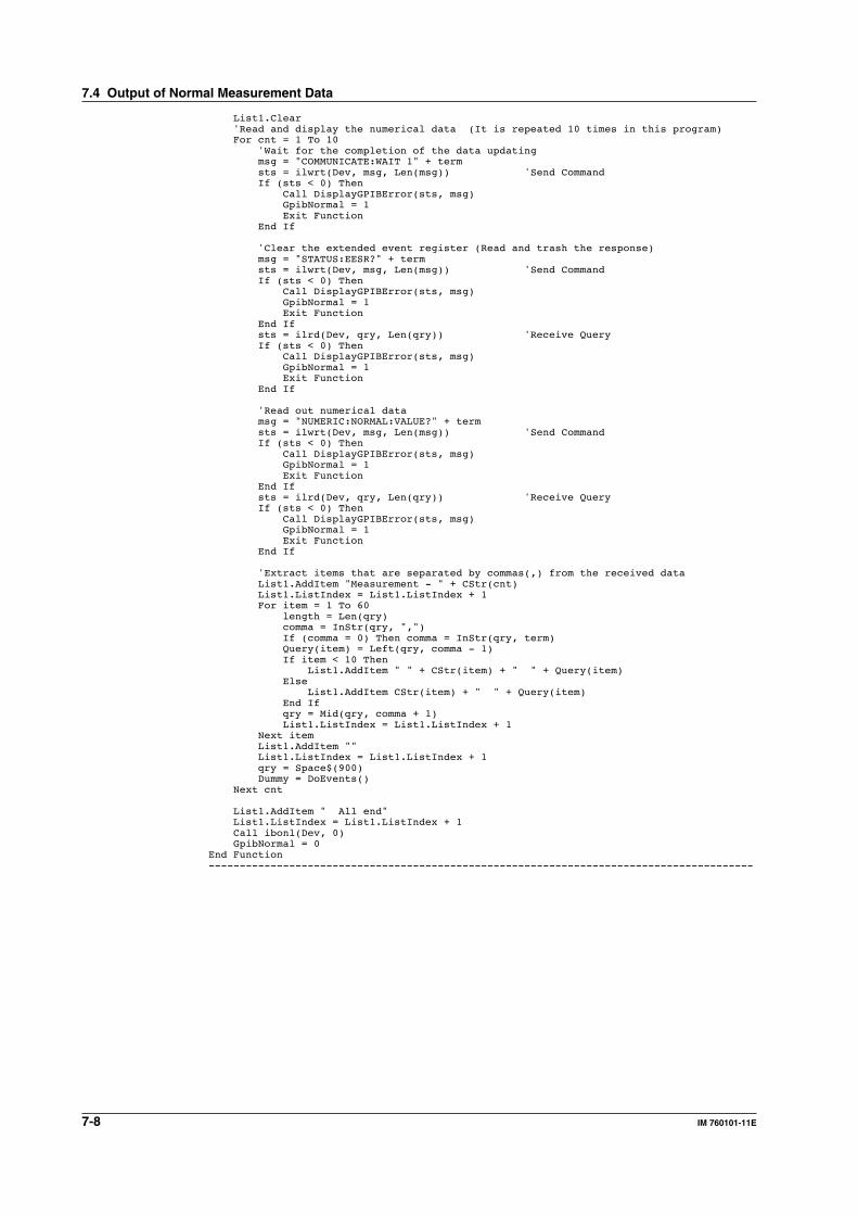
7-8 IM 760101-11E
List1.Clear 'Read and display the numerical data (It is repeated 10 times in this program) For cnt = 1 To 10 'Wait for the completion of the data updating msg = "COMMUNICATE:WAIT 1" + term sts = ilwrt(Dev, msg, Len(msg)) 'Send Command If (sts < 0) Then Call DisplayGPIBError(sts, msg) GpibNormal = 1 Exit Function End If
'Clear the extended event register (Read and trash the response) msg = "STATUS:EESR?" + term sts = ilwrt(Dev, msg, Len(msg)) 'Send Command If (sts < 0) Then Call DisplayGPIBError(sts, msg) GpibNormal = 1 Exit Function End If sts = ilrd(Dev, qry, Len(qry)) 'Receive Query If (sts < 0) Then Call DisplayGPIBError(sts, msg) GpibNormal = 1 Exit Function End If
'Read out numerical data msg = "NUMERIC:NORMAL:VALUE?" + term sts = ilwrt(Dev, msg, Len(msg)) 'Send Command If (sts < 0) Then Call DisplayGPIBError(sts, msg) GpibNormal = 1 Exit Function End If sts = ilrd(Dev, qry, Len(qry)) 'Receive Query If (sts < 0) Then Call DisplayGPIBError(sts, msg) GpibNormal = 1 Exit Function End If
'Extract items that are separated by commas(,) from the received data List1.AddItem "Measurement - " + CStr(cnt) List1.ListIndex = List1.ListIndex + 1 For item = 1 To 60 length = Len(qry) comma = InStr(qry, ",") If (comma = 0) Then comma = InStr(qry, term) Query(item) = Left(qry, comma - 1) If item < 10 Then List1.AddItem " " + CStr(item) + " " + Query(item) Else List1.AddItem CStr(item) + " " + Query(item) End If qry = Mid(qry, comma + 1) List1.ListIndex = List1.ListIndex + 1 Next item List1.AddItem "" List1.ListIndex = List1.ListIndex + 1 qry = Space$(900) Dummy = DoEvents() Next cnt
List1.AddItem " All end" List1.ListIndex = List1.ListIndex + 1 Call ibonl(Dev, 0) GpibNormal = 0End Function----------------------------------------------------------------------------------------
7.4 Output of Normal Measurement Data
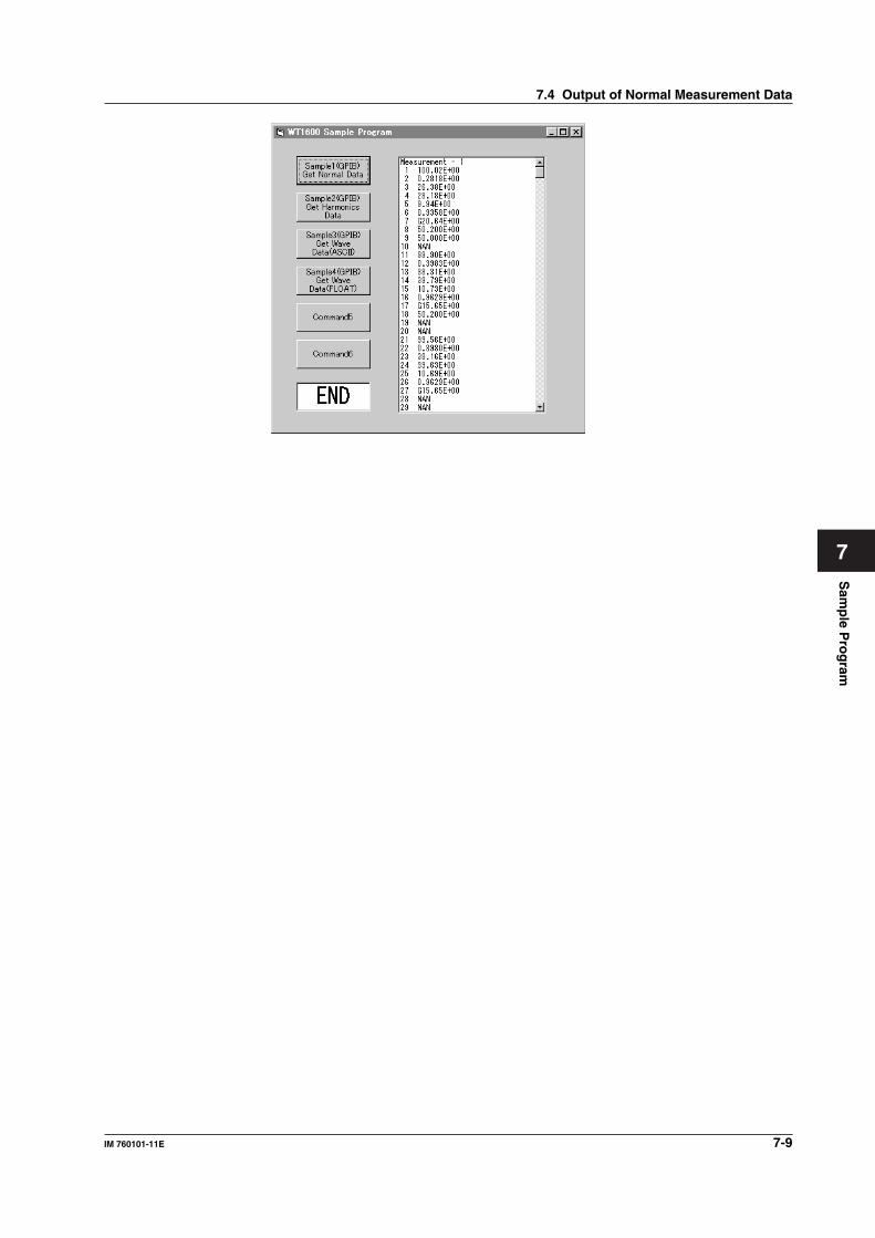
Sam
ple P
rog
ram
7-9IM 760101-11E
7
7.4 Output of Normal Measurement Data
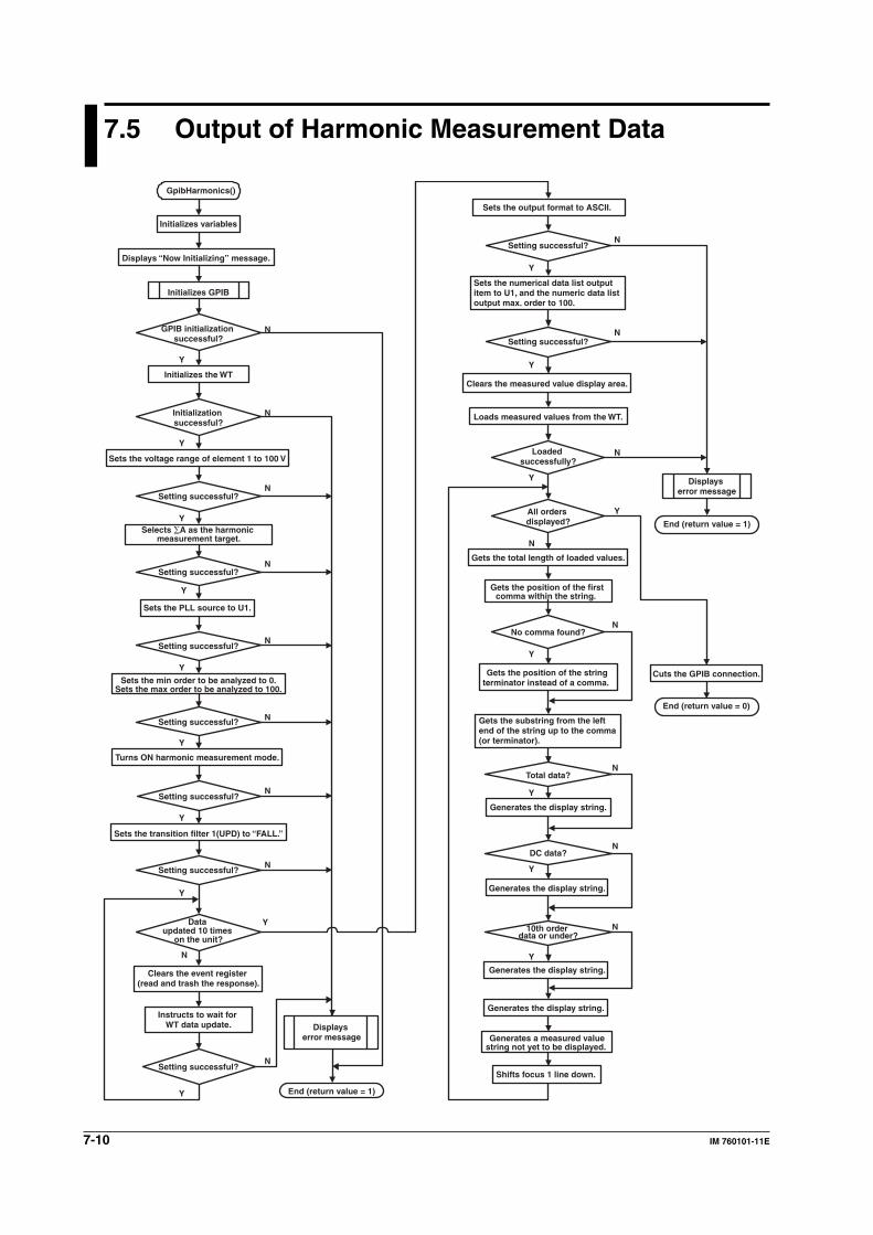
7-10 IM 760101-11E
7.5 Output of Harmonic Measurement Data
GpibHarmonics()
Y
N
Y
N
Y
N
Y
N
Y
N
Y
N
Y
N
Y
N
Y
N
Y
N
Y
N
N
Y
Y
N
Y
N
Y
N
Y
N
Y
N
Y
N
End (return value = 0)
Initializes variables
Displays “Now Initializing” message.
Initializes GPIB
GPIB initialization successful?
Initializes the WT
Initialization successful?
Sets the voltage range of element 1 to 100 V
Setting successful?
Selects ∑A as the harmonic measurement target.
Setting successful?
Sets the PLL source to U1.
Setting successful?
Setting successful?
Turns ON harmonic measurement mode.
Setting successful?
Sets the transition filter 1(UPD) to “FALL.”
Setting successful?
Data updated 10 times
on the unit?
Clears the event register (read and trash the response).
Instructs to wait for WT data update.
Setting successful?
Displays error message
End (return value = 1)
Sets the output format to ASCII.
Setting successful?
Sets the numerical data list output item to U1, and the numeric data list output max. order to 100.
Setting successful?
Clears the measured value display area.
Loads measured values from the WT.
Loaded successfully?
All orders displayed?
Gets the total length of loaded values.
Gets the position of the first comma within the string.
No comma found?
Gets the position of the string terminator instead of a comma.
Gets the substring from the left end of the string up to the comma (or terminator).
Total data?
Generates the display string.
DC data?
Generates the display string.
10th order data or under?
Generates the display string.
Generates the display string.
Generates a measured value string not yet to be displayed.
Shifts focus 1 line down.
Displays error message
End (return value = 1)
Cuts the GPIB connection.Sets the min order to be analyzed to 0.
Sets the max order to be analyzed to 100.
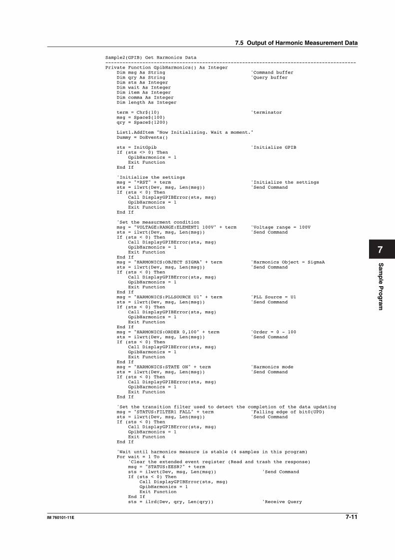
Sam
ple P
rog
ram
7-11IM 760101-11E
7
Sample2(GPIB) Get Harmonics Data----------------------------------------------------------------------------------------Private Function GpibHarmonics() As Integer Dim msg As String 'Command buffer Dim qry As String 'Query buffer Dim sts As Integer Dim wait As Integer Dim item As Integer Dim comma As Integer Dim length As Integer
term = Chr$(10) 'terminator msg = Space$(100) qry = Space$(1200)
List1.AddItem "Now Initializing. Wait a moment." Dummy = DoEvents()
sts = InitGpib 'Initialize GPIB If (sts <> 0) Then GpibHarmonics = 1 Exit Function End If
'Initialize the settings msg = "*RST" + term 'Initialize the settings sts = ilwrt(Dev, msg, Len(msg)) 'Send Command If (sts < 0) Then Call DisplayGPIBError(sts, msg) GpibHarmonics = 1 Exit Function End If
'Set the measurment condition msg = "VOLTAGE:RANGE:ELEMENT1 100V" + term 'Voltage range = 100V sts = ilwrt(Dev, msg, Len(msg)) 'Send Command If (sts < 0) Then Call DisplayGPIBError(sts, msg) GpibHarmonics = 1 Exit Function End If msg = "HARMONICS:OBJECT SIGMA" + term 'Harmonics Object = SigmaA sts = ilwrt(Dev, msg, Len(msg)) 'Send Command If (sts < 0) Then Call DisplayGPIBError(sts, msg) GpibHarmonics = 1 Exit Function End If msg = "HARMONICS:PLLSOURCE U1" + term 'PLL Source = U1 sts = ilwrt(Dev, msg, Len(msg)) 'Send Command If (sts < 0) Then Call DisplayGPIBError(sts, msg) GpibHarmonics = 1 Exit Function End If msg = "HARMONICS:ORDER 0,100" + term 'Order = 0 - 100 sts = ilwrt(Dev, msg, Len(msg)) 'Send Command If (sts < 0) Then Call DisplayGPIBError(sts, msg) GpibHarmonics = 1 Exit Function End If msg = "HARMONICS:STATE ON" + term 'Harmonics mode sts = ilwrt(Dev, msg, Len(msg)) 'Send Command If (sts < 0) Then Call DisplayGPIBError(sts, msg) GpibHarmonics = 1 Exit Function End If
'Set the transition filter used to detect the completion of the data updating msg = "STATUS:FILTER1 FALL" + term 'Falling edge of bit0(UPD) sts = ilwrt(Dev, msg, Len(msg)) 'Send Command If (sts < 0) Then Call DisplayGPIBError(sts, msg) GpibHarmonics = 1 Exit Function End If
'Wait until harmonics measure is stable (4 samples in this program) For wait = 1 To 4 'Clear the extended event register (Read and trash the response) msg = "STATUS:EESR?" + term sts = ilwrt(Dev, msg, Len(msg)) 'Send Command If (sts < 0) Then Call DisplayGPIBError(sts, msg) GpibHarmonics = 1 Exit Function End If sts = ilrd(Dev, qry, Len(qry)) 'Receive Query
7.5 Output of Harmonic Measurement Data
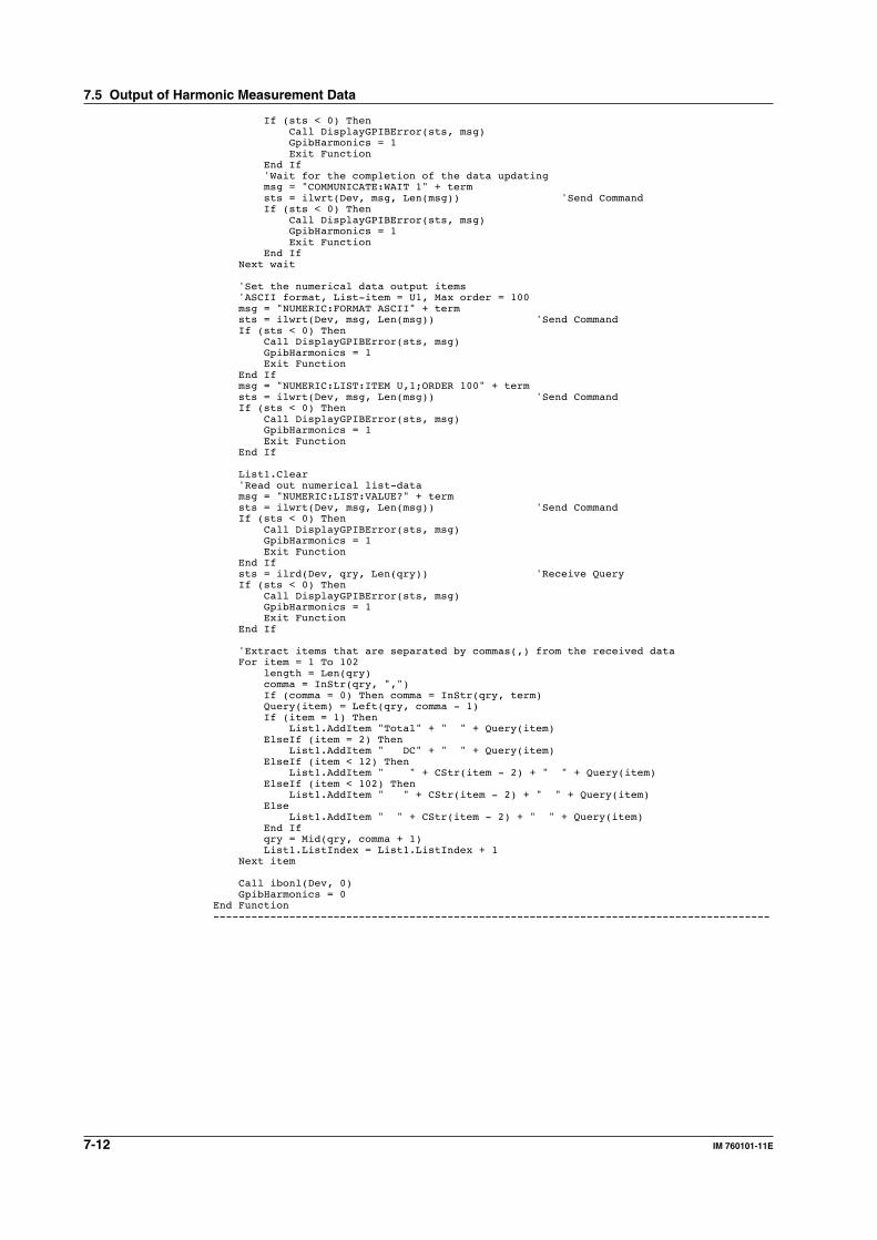
7-12 IM 760101-11E
If (sts < 0) Then Call DisplayGPIBError(sts, msg) GpibHarmonics = 1 Exit Function End If 'Wait for the completion of the data updating msg = "COMMUNICATE:WAIT 1" + term sts = ilwrt(Dev, msg, Len(msg)) 'Send Command If (sts < 0) Then Call DisplayGPIBError(sts, msg) GpibHarmonics = 1 Exit Function End If Next wait
'Set the numerical data output items 'ASCII format, List-item = U1, Max order = 100 msg = "NUMERIC:FORMAT ASCII" + term sts = ilwrt(Dev, msg, Len(msg)) 'Send Command If (sts < 0) Then Call DisplayGPIBError(sts, msg) GpibHarmonics = 1 Exit Function End If msg = "NUMERIC:LIST:ITEM U,1;ORDER 100" + term sts = ilwrt(Dev, msg, Len(msg)) 'Send Command If (sts < 0) Then Call DisplayGPIBError(sts, msg) GpibHarmonics = 1 Exit Function End If
List1.Clear 'Read out numerical list-data msg = "NUMERIC:LIST:VALUE?" + term sts = ilwrt(Dev, msg, Len(msg)) 'Send Command If (sts < 0) Then Call DisplayGPIBError(sts, msg) GpibHarmonics = 1 Exit Function End If sts = ilrd(Dev, qry, Len(qry)) 'Receive Query If (sts < 0) Then Call DisplayGPIBError(sts, msg) GpibHarmonics = 1 Exit Function End If
'Extract items that are separated by commas(,) from the received data For item = 1 To 102 length = Len(qry) comma = InStr(qry, ",") If (comma = 0) Then comma = InStr(qry, term) Query(item) = Left(qry, comma - 1) If (item = 1) Then List1.AddItem "Total" + " " + Query(item) ElseIf (item = 2) Then List1.AddItem " DC" + " " + Query(item) ElseIf (item < 12) Then List1.AddItem " " + CStr(item - 2) + " " + Query(item) ElseIf (item < 102) Then List1.AddItem " " + CStr(item - 2) + " " + Query(item) Else List1.AddItem " " + CStr(item - 2) + " " + Query(item) End If qry = Mid(qry, comma + 1) List1.ListIndex = List1.ListIndex + 1 Next item
Call ibonl(Dev, 0) GpibHarmonics = 0End Function----------------------------------------------------------------------------------------
7.5 Output of Harmonic Measurement Data

Sam
ple P
rog
ram
7-13IM 760101-11E
7
7.5 Output of Harmonic Measurement Data
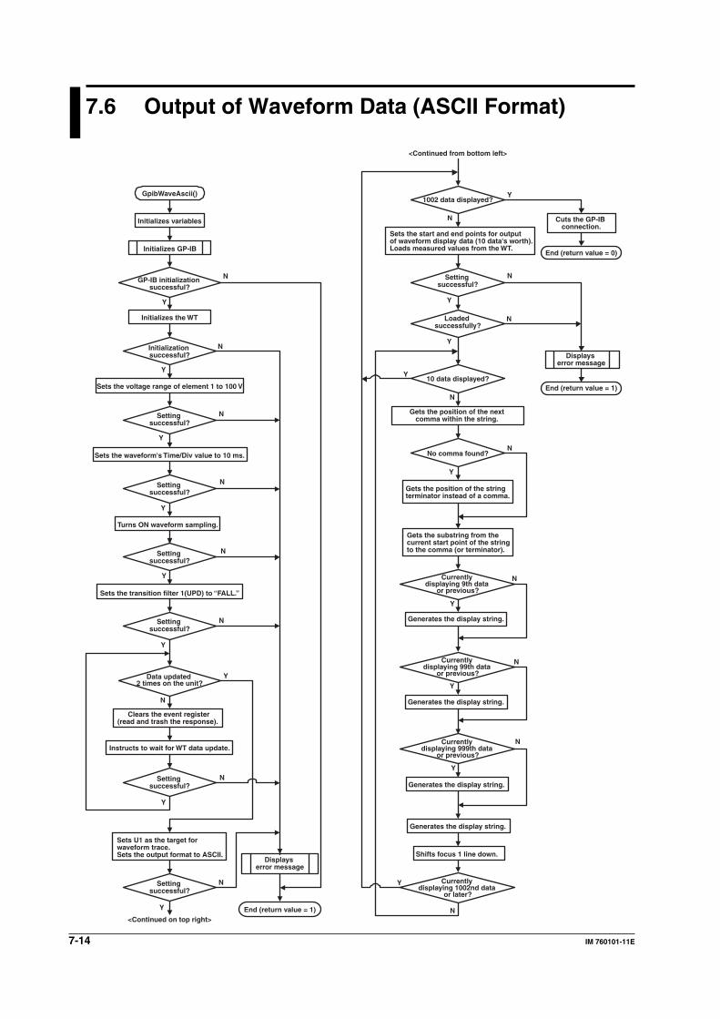
7-14 IM 760101-11E
7.6 Output of Waveform Data (ASCII Format)
Y
N
Y
N
Y
N
Y
N
Y
N
Y
N
Y
N
Y
N
Y
N
Y
N
Y
N
Y
N
Y
N
Y
N
Y
N
N
Y
Y
N
N
Y
GpibWaveAscii()
Initializes variables
Initializes GP-IB
GP-IB initialization successful?
Initializes the WT
Initialization successful?
Sets the voltage range of element 1 to 100 V
Setting successful?
Sets the waveform's Time/Div value to 10 ms.
Setting successful?
Turns ON waveform sampling.
Setting successful?
Sets the transition filter 1(UPD) to “FALL.”
Setting successful?
Data updated 2 times on the unit?
Clears the event register (read and trash the response).
Instructs to wait for WT data update.
Setting successful?
Sets U1 as the target for waveform trace. Sets the output format to ASCII.
Displays error message
End (return value = 1)
Setting successful?
<Continued on top right>
<Continued from bottom left>
1002 data displayed?
Sets the start and end points for output of waveform display data (10 data's worth). Loads measured values from the WT.
Setting successful?
Loaded successfully?
10 data displayed?
Gets the position of the next comma within the string.
No comma found?
Gets the position of the string terminator instead of a comma.
Gets the substring from the current start point of the string to the comma (or terminator).
Currently displaying 9th data
or previous?
Generates the display string.
Currently displaying 99th data
or previous?
Generates the display string.
Currently displaying 999th data
or previous?
Generates the display string.
Generates the display string.
Shifts focus 1 line down.
Currently displaying 1002nd data
or later?
Cuts the GP-IB connection.
End (return value = 0)
Displays error message
End (return value = 1)
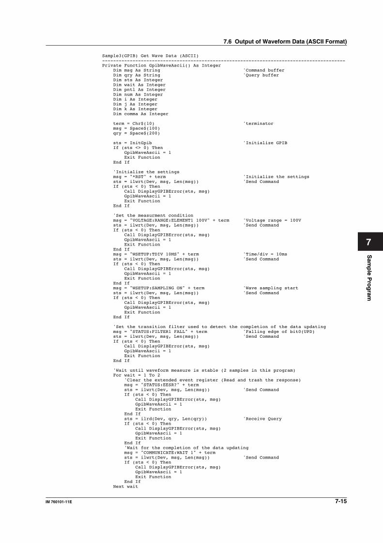
Sam
ple P
rog
ram
7-15IM 760101-11E
7
Sample3(GPIB) Get Wave Data (ASCII)----------------------------------------------------------------------------------------Private Function GpibWaveAscii() As Integer Dim msg As String 'Command buffer Dim qry As String 'Query buffer Dim sts As Integer Dim wait As Integer Dim pntl As Integer Dim num As Integer Dim i As Integer Dim j As Integer Dim k As Integer Dim comma As Integer
term = Chr$(10) 'terminator msg = Space$(100) qry = Space$(200)
sts = InitGpib 'Initialize GPIB If (sts <> 0) Then GpibWaveAscii = 1 Exit Function End If
'Initialize the settings msg = "*RST" + term 'Initialize the settings sts = ilwrt(Dev, msg, Len(msg)) 'Send Command If (sts < 0) Then Call DisplayGPIBError(sts, msg) GpibWaveAscii = 1 Exit Function End If
'Set the measurment condition msg = "VOLTAGE:RANGE:ELEMENT1 100V" + term 'Voltage range = 100V sts = ilwrt(Dev, msg, Len(msg)) 'Send Command If (sts < 0) Then Call DisplayGPIBError(sts, msg) GpibWaveAscii = 1 Exit Function End If msg = "WSETUP:TDIV 10MS" + term 'Time/div = 10ms sts = ilwrt(Dev, msg, Len(msg)) 'Send Command If (sts < 0) Then Call DisplayGPIBError(sts, msg) GpibWaveAscii = 1 Exit Function End If msg = "WSETUP:SAMPLING ON" + term 'Wave sampling start sts = ilwrt(Dev, msg, Len(msg)) 'Send Command If (sts < 0) Then Call DisplayGPIBError(sts, msg) GpibWaveAscii = 1 Exit Function End If
'Set the transition filter used to detect the completion of the data updating msg = "STATUS:FILTER1 FALL" + term 'Falling edge of bit0(UPD) sts = ilwrt(Dev, msg, Len(msg)) 'Send Command If (sts < 0) Then Call DisplayGPIBError(sts, msg) GpibWaveAscii = 1 Exit Function End If
'Wait until waveform measure is stable (2 samples in this program) For wait = 1 To 2 'Clear the extended event register (Read and trash the response) msg = "STATUS:EESR?" + term sts = ilwrt(Dev, msg, Len(msg)) 'Send Command If (sts < 0) Then Call DisplayGPIBError(sts, msg) GpibWaveAscii = 1 Exit Function End If sts = ilrd(Dev, qry, Len(qry)) 'Receive Query If (sts < 0) Then Call DisplayGPIBError(sts, msg) GpibWaveAscii = 1 Exit Function End If 'Wait for the completion of the data updating msg = "COMMUNICATE:WAIT 1" + term sts = ilwrt(Dev, msg, Len(msg)) 'Send Command If (sts < 0) Then Call DisplayGPIBError(sts, msg) GpibWaveAscii = 1 Exit Function End If Next wait
7.6 Output of Waveform Data (ASCII Format)
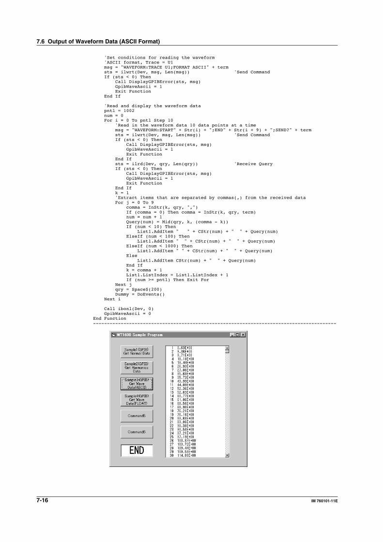
7-16 IM 760101-11E
'Set conditions for reading the waveform 'ASCII format, Trace = U1 msg = "WAVEFORM:TRACE U1;FORMAT ASCII" + term sts = ilwrt(Dev, msg, Len(msg)) 'Send Command If (sts < 0) Then Call DisplayGPIBError(sts, msg) GpibWaveAscii = 1 Exit Function End If
'Read and display the waveform data pntl = 1002 num = 0 For i = 0 To pntl Step 10 'Read in the waveform data 10 data points at a time msg = "WAVEFORM:START" + Str(i) + ";END" + Str(i + 9) + ";SEND?" + term sts = ilwrt(Dev, msg, Len(msg)) 'Send Command If (sts < 0) Then Call DisplayGPIBError(sts, msg) GpibWaveAscii = 1 Exit Function End If sts = ilrd(Dev, qry, Len(qry)) 'Receive Query If (sts < 0) Then Call DisplayGPIBError(sts, msg) GpibWaveAscii = 1 Exit Function End If k = 1 'Extract items that are separated by commas(,) from the received data For j = 0 To 9 comma = InStr(k, qry, ",") If (comma = 0) Then comma = InStr(k, qry, term) num = num + 1 Query(num) = Mid(qry, k, (comma - k)) If (num < 10) Then List1.AddItem " " + CStr(num) + " " + Query(num) ElseIf (num < 100) Then List1.AddItem " " + CStr(num) + " " + Query(num) ElseIf (num < 1000) Then List1.AddItem " " + CStr(num) + " " + Query(num) Else List1.AddItem CStr(num) + " " + Query(num) End If k = comma + 1 List1.ListIndex = List1.ListIndex + 1 If (num >= pntl) Then Exit For Next j qry = Space$(200) Dummy = DoEvents() Next i
Call ibonl(Dev, 0) GpibWaveAscii = 0End Function----------------------------------------------------------------------------------------
7.6 Output of Waveform Data (ASCII Format)
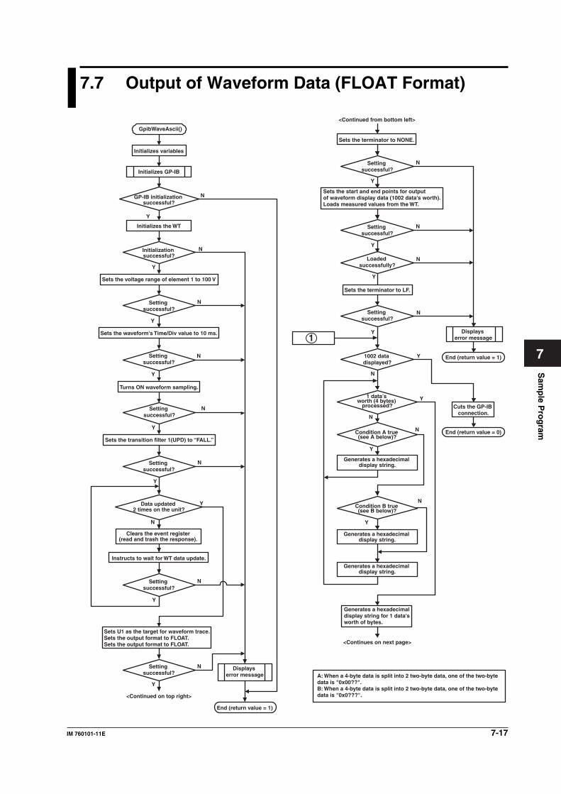
Sam
ple P
rog
ram
7-17IM 760101-11E
7
7.7 Output of Waveform Data (FLOAT Format)
Y
N
Y
N
Y
N
Y
N
Y
N
Y
N
Y
N
Y
N
Y
N
Y
N
N
Y
Y
N
Y
N
Y
N
Y
N
N
Y
N
Y
GpibWaveAscii()
Initializes GP-IB
GP-IB initialization successful?
Initializes the WT
Initialization successful?
Sets the voltage range of element 1 to 100 V
Setting successful?
Sets the waveform's Time/Div value to 10 ms.
Setting successful?
Turns ON waveform sampling.
Setting successful?
Sets the transition filter 1(UPD) to “FALL.”
Setting successful?
Data updated 2 times on the unit?
Clears the event register (read and trash the response).
Instructs to wait for WT data update.
Setting successful?
Sets U1 as the target for waveform trace. Sets the output format to FLOAT.Sets the output format to FLOAT.
Setting successful?
<Continued on top right>
Displays error message
End (return value = 1)
<Continued from bottom left>
Sets the terminator to NONE.
Setting successful?
Sets the start and end points for output of waveform display data (1002 data's worth). Loads measured values from the WT.
Setting successful?
Loaded successfully?
Sets the terminator to LF.
Setting successful?
1002 data displayed?
1 data’s worth (4 bytes)
processed?
Condition A true (see A below)?
Generates a hexadecimal display string.
Condition B true (see B below)?
Generates a hexadecimal display string.
Generates a hexadecimal display string.
Generates a hexadecimal display string for 1 data's worth of bytes.
A: When a 4-byte data is split into 2 two-byte data, one of the two-byte data is "0x00??". B: When a 4-byte data is split into 2 two-byte data, one of the two-byte data is "0x0???".
<Continues on next page>
Displays error message
End (return value = 1)
Cuts the GP-IB connection.
Initializes variables
End (return value = 0)
1
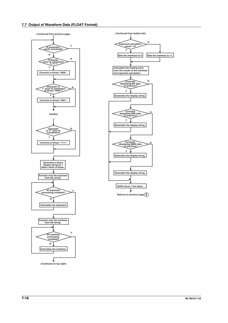
7-18 IM 760101-11E
Y
N
Y
N
Y
N
Y
N
N
Y
N
Y
N
Y
Y
N
Y
N
N
Y
Sets the mantissa to +1.
<Continued from previous page>
8 characters worth converted?
Character prior to conversion
is “0”?
Converts to binary “0000.”
Character is “1” prior to conversion
to binary “0000”?
Converts to binary “0001.”
Omitted
Character is “F” prior to conversion?
Converts to binary “1111.”
Generates a binary display string for 1
data's worth of bytes.
Extracts only the exponent from the string.
All exponent processing complete?
Calculates the exponent.
Extracts only the mantissa from the string.
All mantissa processing complete?
Calculates the mantissa.
<Continued on top right>
<Continued from bottom left>
Exponent calculation result = 0?
Sets the mantissa to 0.
Calculates the floating point from the results of the mantissa and exponent calculation.
Currently displaying 9th data
or previous?
Generates the display string.
Currently displaying 99th data
or previous?
Generates the display string.
Currently displaying 999th data
or previous?
Generates the display string.
Generates the display string.
Shifts focus 1 line down.
Returns to previous page 1
7.7 Output of Waveform Data (FLOAT Format)
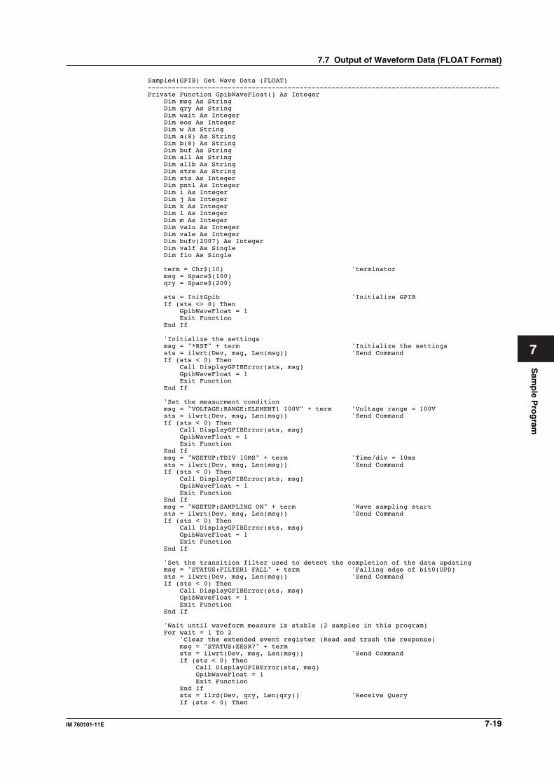
Sam
ple P
rog
ram
7-19IM 760101-11E
7
Sample4(GPIB) Get Wave Data (FLOAT)----------------------------------------------------------------------------------------Private Function GpibWaveFloat() As Integer Dim msg As String Dim qry As String Dim wait As Integer Dim eos As Integer Dim w As String Dim a(8) As String Dim b(8) As String Dim buf As String Dim all As String Dim allb As String Dim stre As String Dim sts As Integer Dim pntl As Integer Dim i As Integer Dim j As Integer Dim k As Integer Dim l As Integer Dim m As Integer Dim valu As Integer Dim vale As Integer Dim bufv(2007) As Integer Dim valf As Single Dim flo As Single
term = Chr$(10) 'terminator msg = Space$(100) qry = Space$(200)
sts = InitGpib 'Initialize GPIB If (sts <> 0) Then GpibWaveFloat = 1 Exit Function End If
'Initialize the settings msg = "*RST" + term 'Initialize the settings sts = ilwrt(Dev, msg, Len(msg)) 'Send Command If (sts < 0) Then Call DisplayGPIBError(sts, msg) GpibWaveFloat = 1 Exit Function End If
'Set the measurment condition msg = "VOLTAGE:RANGE:ELEMENT1 100V" + term 'Voltage range = 100V sts = ilwrt(Dev, msg, Len(msg)) 'Send Command If (sts < 0) Then Call DisplayGPIBError(sts, msg) GpibWaveFloat = 1 Exit Function End If msg = "WSETUP:TDIV 10MS" + term 'Time/div = 10ms sts = ilwrt(Dev, msg, Len(msg)) 'Send Command If (sts < 0) Then Call DisplayGPIBError(sts, msg) GpibWaveFloat = 1 Exit Function End If msg = "WSETUP:SAMPLING ON" + term 'Wave sampling start sts = ilwrt(Dev, msg, Len(msg)) 'Send Command If (sts < 0) Then Call DisplayGPIBError(sts, msg) GpibWaveFloat = 1 Exit Function End If
'Set the transition filter used to detect the completion of the data updating msg = "STATUS:FILTER1 FALL" + term 'Falling edge of bit0(UPD) sts = ilwrt(Dev, msg, Len(msg)) 'Send Command If (sts < 0) Then Call DisplayGPIBError(sts, msg) GpibWaveFloat = 1 Exit Function End If
'Wait until waveform measure is stable (2 samples in this program) For wait = 1 To 2 'Clear the extended event register (Read and trash the response) msg = "STATUS:EESR?" + term sts = ilwrt(Dev, msg, Len(msg)) 'Send Command If (sts < 0) Then Call DisplayGPIBError(sts, msg) GpibWaveFloat = 1 Exit Function End If sts = ilrd(Dev, qry, Len(qry)) 'Receive Query If (sts < 0) Then
7.7 Output of Waveform Data (FLOAT Format)
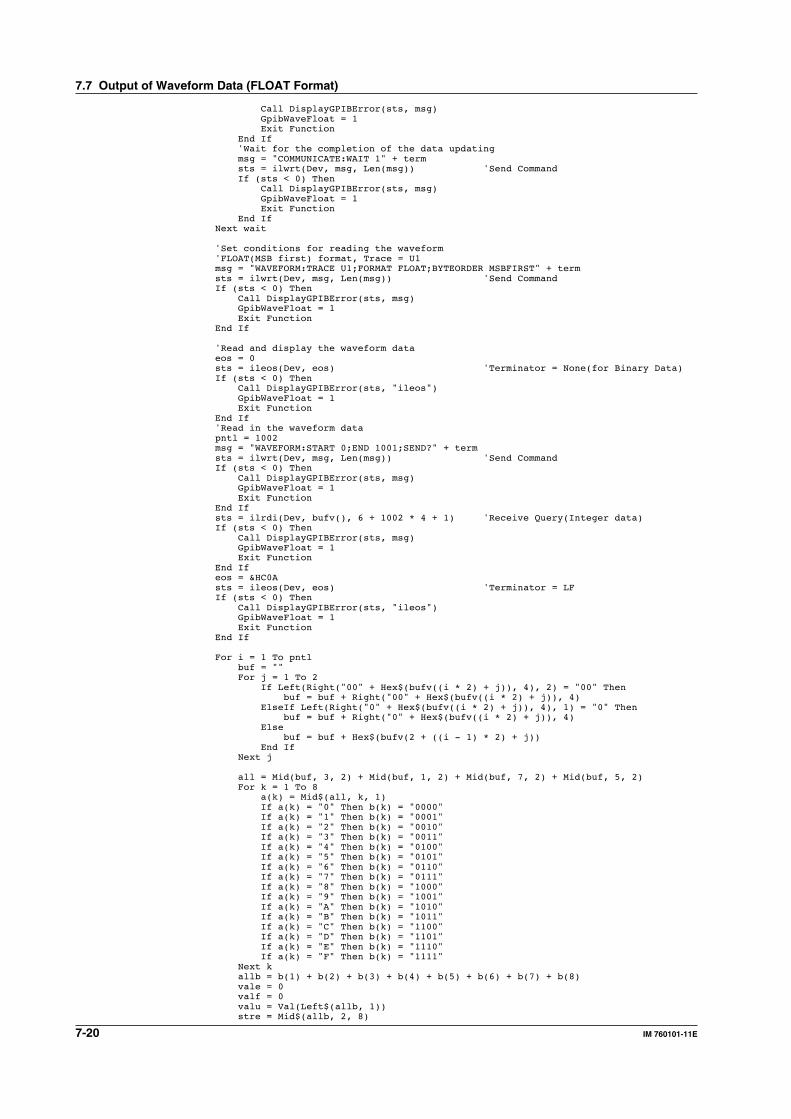
7-20 IM 760101-11E
Call DisplayGPIBError(sts, msg) GpibWaveFloat = 1 Exit Function End If 'Wait for the completion of the data updating msg = "COMMUNICATE:WAIT 1" + term sts = ilwrt(Dev, msg, Len(msg)) 'Send Command If (sts < 0) Then Call DisplayGPIBError(sts, msg) GpibWaveFloat = 1 Exit Function End If Next wait
'Set conditions for reading the waveform 'FLOAT(MSB first) format, Trace = U1 msg = "WAVEFORM:TRACE U1;FORMAT FLOAT;BYTEORDER MSBFIRST" + term sts = ilwrt(Dev, msg, Len(msg)) 'Send Command If (sts < 0) Then Call DisplayGPIBError(sts, msg) GpibWaveFloat = 1 Exit Function End If
'Read and display the waveform data eos = 0 sts = ileos(Dev, eos) 'Terminator = None(for Binary Data) If (sts < 0) Then Call DisplayGPIBError(sts, "ileos") GpibWaveFloat = 1 Exit Function End If 'Read in the waveform data pntl = 1002 msg = "WAVEFORM:START 0;END 1001;SEND?" + term sts = ilwrt(Dev, msg, Len(msg)) 'Send Command If (sts < 0) Then Call DisplayGPIBError(sts, msg) GpibWaveFloat = 1 Exit Function End If sts = ilrdi(Dev, bufv(), 6 + 1002 * 4 + 1) 'Receive Query(Integer data) If (sts < 0) Then Call DisplayGPIBError(sts, msg) GpibWaveFloat = 1 Exit Function End If eos = &HC0A sts = ileos(Dev, eos) 'Terminator = LF If (sts < 0) Then Call DisplayGPIBError(sts, "ileos") GpibWaveFloat = 1 Exit Function End If
For i = 1 To pntl buf = "" For j = 1 To 2 If Left(Right("00" + Hex$(bufv((i * 2) + j)), 4), 2) = "00" Then buf = buf + Right("00" + Hex$(bufv((i * 2) + j)), 4) ElseIf Left(Right("0" + Hex$(bufv((i * 2) + j)), 4), 1) = "0" Then buf = buf + Right("0" + Hex$(bufv((i * 2) + j)), 4) Else buf = buf + Hex$(bufv(2 + ((i - 1) * 2) + j)) End If Next j
all = Mid(buf, 3, 2) + Mid(buf, 1, 2) + Mid(buf, 7, 2) + Mid(buf, 5, 2) For k = 1 To 8 a(k) = Mid$(all, k, 1) If a(k) = "0" Then b(k) = "0000" If a(k) = "1" Then b(k) = "0001" If a(k) = "2" Then b(k) = "0010" If a(k) = "3" Then b(k) = "0011" If a(k) = "4" Then b(k) = "0100" If a(k) = "5" Then b(k) = "0101" If a(k) = "6" Then b(k) = "0110" If a(k) = "7" Then b(k) = "0111" If a(k) = "8" Then b(k) = "1000" If a(k) = "9" Then b(k) = "1001" If a(k) = "A" Then b(k) = "1010" If a(k) = "B" Then b(k) = "1011" If a(k) = "C" Then b(k) = "1100" If a(k) = "D" Then b(k) = "1101" If a(k) = "E" Then b(k) = "1110" If a(k) = "F" Then b(k) = "1111" Next k allb = b(1) + b(2) + b(3) + b(4) + b(5) + b(6) + b(7) + b(8) vale = 0 valf = 0 valu = Val(Left$(allb, 1)) stre = Mid$(allb, 2, 8)
7.7 Output of Waveform Data (FLOAT Format)
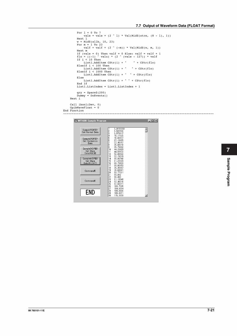
Sam
ple P
rog
ram
7-21IM 760101-11E
7
For l = 0 To 7 vale = vale + (2 ^ l) * Val(Mid$(stre, (8 - l), 1)) Next l w = Mid$(allb, 10, 23) For m = 1 To 23 valf = valf + (2 ^ (-m)) * Val(Mid$(w, m, 1)) Next m If (vale = 0) Then valf = 0 Else: valf = valf + 1 flo = ((-1) ^ valu) * (2 ^ (vale - 127)) * valf If i < 10 Then List1.AddItem CStr(i) + " " + CStr(flo) ElseIf i < 100 Then List1.AddItem CStr(i) + " " + CStr(flo) ElseIf i < 1000 Then List1.AddItem CStr(i) + " " + CStr(flo) Else List1.AddItem CStr(i) + " " + CStr(flo) End If List1.ListIndex = List1.ListIndex + 1
qry = Space$(200) Dummy = DoEvents() Next i
Call ibonl(Dev, 0) GpibWaveFloat = 0End Function----------------------------------------------------------------------------------------
7.7 Output of Waveform Data (FLOAT Format)
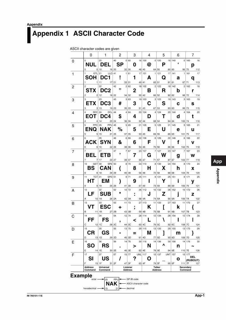
Ap
pen
dix
App-1IM 760101-11E
App
Appendix 1 ASCII Character Code
ASCII character codes are given
0
1
2
3
4
5
6
7
10
11
12
13
14
15
16
17
NUL
SOH
STX
ETX
EOT
ENQ
ACK
BEL
BS
HT
LF
VT
FF
CR
SO
SI
20
21
22
23
24
25
26
27
30
31
32
33
34
35
36
37
40
41
42
43
44
45
46
47
50
51
52
53
54
55
56
57
60
61
62
63
64
65
66
67
70
71
72
73
74
75
76
77
100
101
102
103
104
105
106
107
110
111
112
113
114
115
116
117
120
121
122
123
124
125
126
127
130
131
132
133
134
135
136
137
140
141
142
143
144
145
146
147
150
151
152
153
154
155
156
157
160
161
162
163
164
165
166
167
170
171
172
173
174
175
176
177
0
1
2
3
4
5
6
7
8
9
A
B
C
D
E
F
0
1
2
3
4
5
6
7
8
9
A
B
C
D
E
F
10
11
12
13
14
15
16
17
18
19
1A
1B
1C
1D
1E
1F
20
21
22
23
24
25
26
27
28
29
2A
2B
2C
2D
2E
2F
30
31
32
33
34
35
36
37
38
39
3A
3B
3C
3D
3E
3F
40
41
42
43
44
45
46
47
48
49
4A
4B
4C
4D
4E
4F
50
51
52
53
54
55
56
57
58
59
5A
5B
5C
5D
5E
5F
60
61
62
63
64
65
66
67
68
69
6A
6B
6C
6D
6E
6F
70
71
72
73
74
75
76
77
78
79
7A
7B
7C
7D
7E
7F
0
1
2
3
4
5
6
7
8
9
10
11
12
13
14
15
16
17
18
19
20
21
22
23
24
25
26
27
28
29
30
31
32
33
34
35
36
37
38
39
40
41
42
43
44
45
46
47
48
49
50
51
52
53
54
55
56
57
58
59
60
61
62
63
64
65
66
67
68
69
70
71
72
73
74
75
76
77
78
79
80
81
82
83
84
85
86
87
88
89
90
91
92
93
94
95
96
97
98
99
100
101
102
103
104
105
106
107
108
109
110
111
112
113
114
115
116
117
118
119
120
121
122
123
124
125
126
127
GTL
SDC
PPC
GET
TCT
LLO
DCL
PPU
SPE
SPD
0
1
2
3
4
5
6
7
8
9
10
11
12
13
14
15
16
17
18
19
20
21
22
23
24
25
26
27
28
29
30
UNL
DEL
DC1
DC2
DC3
DC4
NAK
SYN
ETB
CAN
EM
SUB
ESC
FS
GS
RS
US
SP
!
”
#
$
%
&
’
(
)
*
+
,
-
.
/
0
1
2
3
4
5
6
7
8
9
:
;
<
=
>
?
@
A
B
C
D
E
F
G
H
I
J
K
L
M
N
O
P
Q
R
S
T
U
V
W
X
Y
Z
[
\
]
^
_
‘
a
b
c
d
e
f
g
h
i
j
k
l
m
n
o
p
q
r
s
t
u
v
w
x
y
z
{
|
}
~
DEL(RUBOUT)
0
1
2
3
4
5
6
7
8
9
10
11
12
13
14
15
16
17
18
19
20
21
22
23
24
25
26
27
28
29
30
UNT
0
1
2
3
4
5
6
7
8
9
10
11
12
13
14
15
16
17
18
19
20
21
22
23
24
25
26
27
28
29
30
AddressCommand
UniversalCommand
ListenerAddress
TalkerAddress
SecondaryCommand
25
15 21
PPU
NAKoctal
hexadecimal
GP-IB code
decimal
ASCII character code
Example
0 1 2 3 4 5 6 7
Appendix
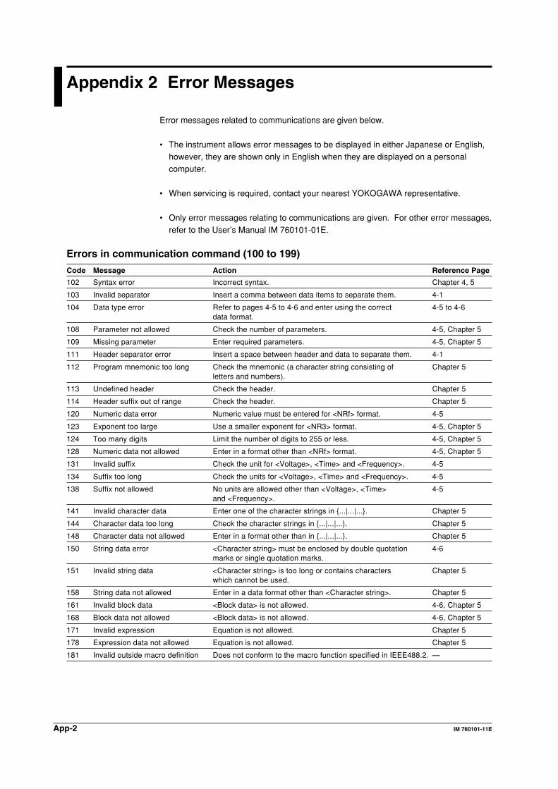
App-2 IM 760101-11E
Appendix 2 Error Messages
Error messages related to communications are given below.
• The instrument allows error messages to be displayed in either Japanese or English,however, they are shown only in English when they are displayed on a personalcomputer.
• When servicing is required, contact your nearest YOKOGAWA representative.
• Only error messages relating to communications are given. For other error messages,refer to the User’s Manual IM 760101-01E.
Errors in communication command (100 to 199)
Code Message Action Reference Page
102 Syntax error Incorrect syntax. Chapter 4, 5
103 Invalid separator Insert a comma between data items to separate them. 4-1
104 Data type error Refer to pages 4-5 to 4-6 and enter using the correct 4-5 to 4-6data format.
108 Parameter not allowed Check the number of parameters. 4-5, Chapter 5
109 Missing parameter Enter required parameters. 4-5, Chapter 5
111 Header separator error Insert a space between header and data to separate them. 4-1
112 Program mnemonic too long Check the mnemonic (a character string consisting of Chapter 5letters and numbers).
113 Undefined header Check the header. Chapter 5
114 Header suffix out of range Check the header. Chapter 5
120 Numeric data error Numeric value must be entered for <NRf> format. 4-5
123 Exponent too large Use a smaller exponent for <NR3> format. 4-5, Chapter 5
124 Too many digits Limit the number of digits to 255 or less. 4-5, Chapter 5
128 Numeric data not allowed Enter in a format other than <NRf> format. 4-5, Chapter 5
131 Invalid suffix Check the unit for <Voltage>, <Time> and <Frequency>. 4-5
134 Suffix too long Check the units for <Voltage>, <Time> and <Frequency>. 4-5
138 Suffix not allowed No units are allowed other than <Voltage>, <Time> 4-5and <Frequency>.
141 Invalid character data Enter one of the character strings in {...|...|...}. Chapter 5
144 Character data too long Check the character strings in {...|...|...}. Chapter 5
148 Character data not allowed Enter in a format other than in {...|...|...}. Chapter 5
150 String data error <Character string> must be enclosed by double quotation 4-6marks or single quotation marks.
151 Invalid string data <Character string> is too long or contains characters Chapter 5which cannot be used.
158 String data not allowed Enter in a data format other than <Character string>. Chapter 5
161 Invalid block data <Block data> is not allowed. 4-6, Chapter 5
168 Block data not allowed <Block data> is not allowed. 4-6, Chapter 5
171 Invalid expression Equation is not allowed. Chapter 5
178 Expression data not allowed Equation is not allowed. Chapter 5
181 Invalid outside macro definition Does not conform to the macro function specified in IEEE488.2. —
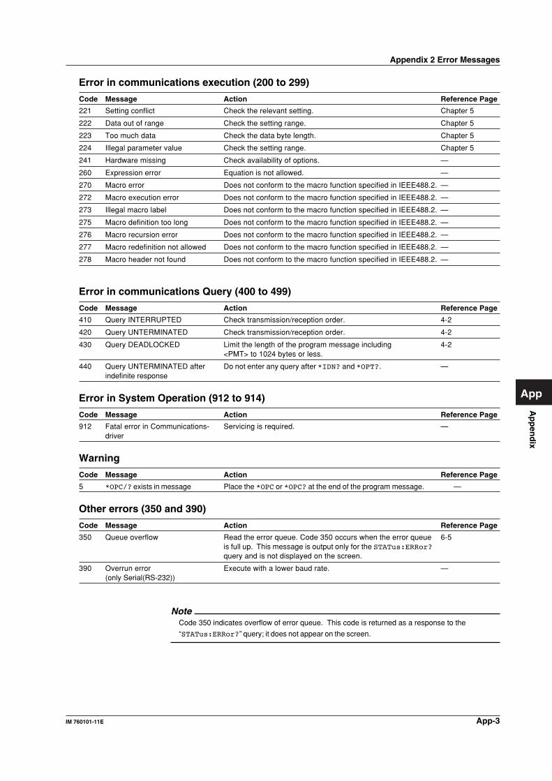
Ap
pen
dix
App-3IM 760101-11E
App
Error in communications execution (200 to 299)
Code Message Action Reference Page
221 Setting conflict Check the relevant setting. Chapter 5
222 Data out of range Check the setting range. Chapter 5
223 Too much data Check the data byte length. Chapter 5
224 Illegal parameter value Check the setting range. Chapter 5
241 Hardware missing Check availability of options. —
260 Expression error Equation is not allowed. —
270 Macro error Does not conform to the macro function specified in IEEE488.2. —
272 Macro execution error Does not conform to the macro function specified in IEEE488.2. —
273 Illegal macro label Does not conform to the macro function specified in IEEE488.2. —
275 Macro definition too long Does not conform to the macro function specified in IEEE488.2. —
276 Macro recursion error Does not conform to the macro function specified in IEEE488.2. —
277 Macro redefinition not allowed Does not conform to the macro function specified in IEEE488.2. —
278 Macro header not found Does not conform to the macro function specified in IEEE488.2. —
Error in communications Query (400 to 499)
Code Message Action Reference Page
410 Query INTERRUPTED Check transmission/reception order. 4-2
420 Query UNTERMINATED Check transmission/reception order. 4-2
430 Query DEADLOCKED Limit the length of the program message including 4-2<PMT> to 1024 bytes or less.
440 Query UNTERMINATED after Do not enter any query after *IDN? and *OPT?. —indefinite response
Error in System Operation (912 to 914)
Code Message Action Reference Page
912 Fatal error in Communications- Servicing is required. —driver
Warning
Code Message Action Reference Page
5 *OPC/? exists in message Place the *OPC or *OPC? at the end of the program message. —
Other errors (350 and 390)
Code Message Action Reference Page
350 Queue overflow Read the error queue. Code 350 occurs when the error queue 6-5is full up. This message is output only for the STATus:ERRor?query and is not displayed on the screen.
390 Overrun error Execute with a lower baud rate. —(only Serial(RS-232))
NoteCode 350 indicates overflow of error queue. This code is returned as a response to the
“STATus:ERRor?” query; it does not appear on the screen.
Appendix 2 Error Messages
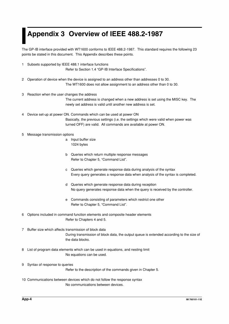
App-4 IM 760101-11E
Appendix 3 Overview of IEEE 488.2-1987
The GP-IB interface provided with WT1600 conforms to IEEE 488.2-1987. This standard requires the following 23points be stated in this document. This Appendix describes these points.
1 Subsets supported by IEEE 488.1 interface functionsRefer to Section 1.4 “GP-IB Interface Specifications”.
2 Operation of device when the device is assigned to an address other than addresses 0 to 30.The WT1600 does not allow assignment to an address other than 0 to 30.
3 Reaction when the user changes the addressThe current address is changed when a new address is set using the MISC key. The
newly set address is valid until another new address is set.
4 Device set-up at power ON. Commands which can be used at power ON
Basically, the previous settings (i.e. the settings which were valid when power wasturned OFF) are valid. All commands are available at power ON.
5 Message transmission optionsa Input buffer size
1024 bytes
b Queries which return multiple response messagesRefer to Chapter 5, “Command List”.
c Queries which generate response data during analysis of the syntaxEvery query generates a response data when analysis of the syntax is completed.
d Queries which generate response data during receptionNo query generates response data when the query is received by the controller.
e Commands consisting of parameters which restrict one otherRefer to Chapter 5, “Command List”.
6 Options included in command function elements and composite header elementsRefer to Chapters 4 and 5.
7 Buffer size which affects transmission of block dataDuring transmission of block data, the output queue is extended according to the size of
the data blocks.
8 List of program data elements which can be used in equations, and nesting limit
No equations can be used.
9 Syntax of response to queries
Refer to the description of the commands given in Chapter 5.
10 Communications between devices which do not follow the response syntax
No communications between devices.
Ap
pen
dix
App-5IM 760101-11E
App
11 Size of data block of response data1 to 308922 bytes
12 List of supported common commandsRefer to Section 5.22 “Common Command Group”.
13 Condition of device when calibration is successfully completedSame as the one under which measurements are performed
14 Maximum length of block data which can be used for definition of *DDT trigger macroNot supported
15 Maximum length of macro label used in definition of macro, maximum length of block data which can be used fordefinition of macro, processing when recursion is used in definition of macro
Macro functions are not supported.
16 Response to *IDN?
Refer to Section 5.22 “Common Command Group”.
17 Size of storage area for protected user data for PUD and *PUD?
*PUD and *PUD? are not supported.
18 Length of *RDT and *RDT? resource name
*RDT and *RDT? are not supported.
19 Change in status due to *RST, *LRN?, *RCL and *SAV
*RST
Refer to Section 5.22 “Common Command Group”.*LRN?, *RCL, *SAV
These commands are not supported.
20 Execution range of self-test using the *TST?
All the memory tests (for each internal memory) given in the Self Test menu displayedusing the MISC can be executed.
21 Structure of extended return statusRefer to Chapter 6.
22 To find out whether each command is performed in parallel or sequentiallyRefer to Section 4.5 “Synchronization with the Controller” and to Chapter 5.
23 Description of execution of each commandRefer to Chapter 5 of this manual and to the User’s Manual IM 760101-01E.
Appendix 3 Overview of IEEE 488.2-1987
Ind
ex
Index-1IM 760101-11E
Index
Index
data list .............................................................................. 5-68
DCL ..................................................................................... 1-6
deadlock .............................................................................. 4-2
default ............................................................................... 5-89
delta computation .............................................................. 5-60
DISPlay group ................................................................... 5-20
drive .................................................................................. 5-35
E
element type ..................................................................... 5-51
enable registers .................................................................. 6-2
Entering TCP/IP Settings .................................................... 3-4
error messages .............................................................. App-2
error queue ............................................................... 5-88, 6-5
Ethernet Control Settings .................................................... 3-3
Ethernet Interface Specifications ........................................ 3-2
extended event enable register ......................................... 5-74
extended event register ........................ 5-15, 5-74, 5-88, 6-4
F
feeding .............................................................................. 5-44
FILE group ........................................................................ 5-33
filename .............................................................................. 4-7
filter ........................................................................... 5-50, 6-4
floppy disk ......................................................................... 5-35
free software ....................................................................... 3-4
frequency measurement source ....................................... 5-64
front panel ........................................................... 1-1, 2-1, 3-1
function names ........................................................ 5-31, 5-32
G
GET ..................................................................................... 1-6
GP-IB cable ......................................................................... 1-2
GP-IB connector ................................................................. 1-1
GP-IB interface specifications ............................................. 1-4
graticule ............................................................................ 5-30
GTL ..................................................................................... 1-6
H
handshaking ................................................................ 2-5, 2-9
hard disk ........................................................................... 5-82
hardware handshaking ........................................................ 2-2
HARMonics Group ............................................................ 5-38
HCOPy group .................................................................... 5-40
HOLD group ...................................................................... 5-45
horizontal axis ................................................................... 5-29
A
address commands ............................................................. 1-7
AOUTput group ................................................................. 5-12
ASCII character codes ................................................... App-1
auto calibration .................................................................. 5-55
automatically name ........................................................... 5-35
averaging coefficient ......................................................... 5-59
averaging type .................................................................. 5-59
B
bar graph ........................................................................... 5-23
baud rate ..................................................................... 2-2, 2-9
bit masking .................................................................. 6-2, 6-3
block data ............................................................................ 4-7
boolean ............................................................................... 4-6
C
calibration .......................................................................... 5-88
CCITT ................................................................................. 2-4
character data ..................................................................... 4-6
command list ....................................................................... 5-1
commands .......................................................................... 5-1
comment ........................................................................... 5-35
common command group ................................................. 5-88
common command header ................................................. 4-3
COMMunicate group ......................................................... 5-14
Communication ........................................................... 1-5, 2-8
communication status ....................................................... 5-74
compound header ............................................................... 4-3
computation mode ............................................................ 5-60
condition register ....................................................... 5-74, 6-4
connector ............................................................................ 2-3
conventions ............................................................................ ii
corrected power ................................................................ 5-61
CS-RS ................................................................................. 2-6
CT ..................................................................................... 5-52
current integration ............................................................. 5-55
current mode ..................................................................... 5-55
current ranges ................................................................... 5-49
current sensor ................................................................... 5-50
CURSor group .................................................................. 5-17
D
D/A output ......................................................................... 5-12
data ..................................................................................... 4-5
data byte string ................................................................... 4-7
data format .......................................................................... 2-7
data length ........................................................ 2-2, 2-9, 5-39
Index-2 IM 760101-11E
Index
I
IDY ...................................................................................... 1-6
IFC ...................................................................................... 1-6
IMAGe Group .................................................................... 5-45
individual element integration ........................................... 5-56
initialization ....................................................................... 5-77
input filter .......................................................................... 5-63
INPut group ....................................................................... 5-46
input type .......................................................................... 5-64
instrument model .............................................................. 5-89
INTEGrate Group .............................................................. 5-54
integration mode ............................................................... 5-56
integration timer ................................................................ 5-57
interface messages ............................................................. 1-6
interpolation ...................................................................... 5-30
interpretation rules .............................................................. 4-4
L
label .................................................................................. 5-30
language ........................................................................... 5-81
LCD monitor ...................................................................... 5-81
line filter ................................................................... 5-51, 5-63
list display ......................................................................... 5-25
listener function ................................................................... 1-3
LLO ..................................................................................... 1-6
LOCAL key .................................................................. 1-1, 2-1
local lockout ...................................................................... 5-14
M
mapping ............................................................................ 5-30
MAX HOLD ....................................................................... 5-61
MEASure group ................................................................ 5-58
message ........................................................................... 5-81
MISC ........................................................................... 1-5, 2-8
MISC key .................................................................... 1-1, 2-1
motor evaluation ............................................................... 5-63
MOTor group ..................................................................... 5-62
motor output ...................................................................... 5-63
multi-line messageE ............................................................ 1-7
multiplier .............................................................................. 4-6
N
names of the parts ...................................................... 1-1, 2-1
NULL ................................................................................. 5-51
NUMeric group .................................................................. 5-66
numerical data .................................................................. 5-67
numerical data format ....................................................... 5-70
numerical display .............................................................. 5-23
O
OFF-OFF ............................................................................ 2-5
options .............................................................................. 5-89
orders ................................................................................ 5-39
overlap commands .................................................... 4-7, 5-15
overlap enable register ..................................................... 5-16
P
paper ................................................................................. 5-44
parity ........................................................................... 2-2, 2-9
password ..................................................................... 3-3, 3-4
path ................................................................................... 5-35
pattern ..................................................................... 5-68, 5-70
Pc ...................................................................................... 5-61
phase difference ................................................................ 5-61
PLL source ........................................................................ 5-39
PMT .................................................................................... 4-1
poles ................................................................................. 5-63
polling ................................................................................ 5-74
preset ................................................................................ 5-68
preset pattern .................................................................... 5-70
program data ....................................................................... 4-1
program header .................................................................. 4-1
program messages ............................................................. 4-1
PT ..................................................................................... 5-52
Q
query ................................................................................... 4-4
queue .................................................................................. 6-5
queues ................................................................................ 6-2
R
range ................................................................................. 5-64
ranges ..................................................................... 5-49, 5-53
RATE group ....................................................................... 5-73
reactive power ................................................................... 5-61
real-time integration .......................................................... 5-56
real-time store ................................................................... 5-79
rear panel ............................................................ 1-1, 2-1, 3-1
recall ................................................................................. 5-76
receive ................................................................................ 2-2
receive buffer ...................................................................... 2-6
receiving function ........................................................ 2-2, 3-2
register ................................................................................ 4-6
registers .............................................................................. 6-2
REMOTE indicator ...................................................... 1-1, 2-1
remote mode ..................................................................... 5-15
REN .................................................................................... 1-6
response ............................................................................. 4-5
response data ..................................................................... 4-2
response header ................................................................. 4-2
response messages ............................................................ 4-1
Ind
ex
Index-3IM 760101-11E
Index
Index
restarts .............................................................................. 5-29
retail software ...................................................................... 3-4
revolution sensor ............................................................... 5-63
RMT .................................................................................... 4-1
rotating speed ................................................................... 5-64
RS-232 ................................................................................ 2-4
S
sample programs ................................................................ 7-1
scaling ............................................................................... 5-51
SCSI device ...................................................................... 5-35
SCSI-ID ............................................................................. 5-82
SDC .................................................................................... 1-6
self-test ............................................................................. 5-90
sending function .......................................................... 2-2, 3-2
sensor ............................................................................... 5-50
sequential commands ......................................................... 4-7
serial (RS-232) connector ................................................... 2-1
serial interface specifications .............................................. 2-2
serial standard signals ........................................................ 2-4
service request enable register ......................................... 5-90
setting the address .............................................................. 1-5
SFACtor ............................................................................ 5-52
signal names ....................................................................... 2-3
simple header ..................................................................... 4-3
size of data block of response data ............................... App-5
software Handshaking ........................................................ 2-2
SPD ..................................................................................... 1-6
SPE ..................................................................................... 1-6
speed ................................................................................ 5-63
standard event enable register ......................................... 5-88
standard event register ............................................. 5-88, 6-3
status bit ............................................................................ 5-15
status byte ........................................................................... 6-2
status byte register ............................................................ 5-90
STATus group .................................................................... 5-73
status register ................................................................... 5-16
status report ........................................................................ 6-1
stop bit ................................................................................ 2-9
store .................................................................................. 5-76
STORe group .................................................................... 5-75
string data ........................................................................... 4-6
Switching between Remote and Local Mode ...................... 3-2
symbols .................................................................................. ii
synchronization ................................................................... 4-7
synchronization source ........................................... 5-52, 5-64
system ............................................................................... 5-80
SYSTem group .................................................................. 5-80
T
talker function ...................................................................... 1-3
terminator ............................................................................ 2-9
THD ................................................................................... 5-39
Time/div ............................................................................. 5-86
timeout time ................................................................ 3-3, 3-4
torque meter signal ........................................................... 5-64
trademark ................................................................................ i
transition filter ............................................................ 5-74, 6-4
trend .................................................................................. 5-26
trigger ................................................................................ 5-86
U
uni-line messages ............................................................... 1-6
universal commands ........................................................... 1-7
user name ................................................................... 3-3, 3-4
user-defined function ........................................................ 5-60
V
vector ................................................................................ 5-29
vertical position ................................................................. 5-86
vertical zoom ..................................................................... 5-87
Visual Basic ......................................................................... 7-1
voltage ranges .................................................................. 5-53
W
waveform .......................................................................... 5-30
waveform display .............................................................. 5-83
WAVeform group ............................................................... 5-83
wiring system .................................................................... 5-53
WSETup group .................................................................. 5-85
X
XON-RS .............................................................................. 2-6
XON-XON ........................................................................... 2-5
Z
zero calibration .................................................................. 5-88
zero-crossing filter ............................................................. 5-51
zoom ................................................................................. 5-87
Command List
*CAL? ................................................................................ 5-88
*CLS .................................................................................. 5-88
*ESE ................................................................................. 5-88
*ESR? ............................................................................... 5-89
*IDN? ................................................................................ 5-89
*OPC ................................................................................. 5-89
*OPC? ............................................................................... 5-89
*OPT? ............................................................................... 5-89
*PSC ................................................................................. 5-89
*RST ................................................................................. 5-89
*SRE ................................................................................. 5-90
*STB? ................................................................................ 5-90
Index-4 IM 760101-11E
Index
*TRG ................................................................................. 5-90
*TST? ................................................................................ 5-90
*WAI .................................................................................. 5-90
:AOUTput:HARMonics:CHANnel<x> ................................ 5-12
:AOUTput:HARMonics? .................................................... 5-12
:AOUTput:NORMal? ......................................................... 5-13
:AOUTput? ........................................................................ 5-12
:AOUTput[:NORMal]:CHANnel<x> ................................... 5-13
:AOUTput[:NORMal]:IRTime ............................................. 5-13
:COMMunicate:HEADer .................................................... 5-14
:COMMunicate:LOCKout .................................................. 5-14
:COMMunicate:OPSE ....................................................... 5-15
:COMMunicate:OPSR? ..................................................... 5-15
:COMMunicate:OVERlap .................................................. 5-15
:COMMunicate:REMote .................................................... 5-15
:COMMunicate:STATus? ................................................... 5-15
:COMMunicate:VERBose ................................................. 5-15
:COMMunicate:WAIT ........................................................ 5-15
:COMMunicate:WAIT? ...................................................... 5-16
:COMMunicate? ................................................................ 5-14
:CURSor:BAR:{Y<x>|DY}? ................................................ 5-18
:CURSor:BAR:POSition<x> .............................................. 5-18
:CURSor:BAR? ................................................................. 5-18
:CURSor:BAR[:STATe] ...................................................... 5-18
:CURSor:TRENd:{X<x>|Y<x>|DY}? .................................. 5-19
:CURSor:TRENd:POSition<x> .......................................... 5-18
:CURSor:TRENd:TRACe<x> ............................................ 5-19
:CURSor:TRENd? ............................................................. 5-18
:CURSor:TRENd[:STATe] .................................................. 5-19
:CURSor:WAVE:{X<x>|DX|PERDt|Y<x>|DY}? .................. 5-19
:CURSor:WAVE:PATH ...................................................... 5-19
:CURSor:WAVE:POSition<x> ........................................... 5-19
:CURSor:WAVE:TRACe<x> .............................................. 5-19
:CURSor:WAVE? .............................................................. 5-19
:CURSor:WAVE[:STATe] ................................................... 5-19
:CURSor? .......................................................................... 5-18
:DISPlay:BAR:FORMat ..................................................... 5-23
:DISPlay:BAR:ITEM<x> .................................................... 5-23
:DISPlay:BAR:ORDer ....................................................... 5-23
:DISPlay:BAR? .................................................................. 5-23
:DISPlay:FORMat ............................................................. 5-23
:DISPlay:NUMeric? ........................................................... 5-23
:DISPlay:TRENd:ALL ........................................................ 5-27
:DISPlay:TRENd:FORMat ................................................. 5-27
:DISPlay:TRENd:HARMonics:ITEM<x>:SCALing:MODE
...................................................................................... 5-27
:DISPlay:TRENd:HARMonics:ITEM<x>:SCALing:VALue
...................................................................................... 5-28
:DISPlay:TRENd:HARMonics:ITEM<x>:SCALing? .......... 5-27
:DISPlay:TRENd:HARMonics:ITEM<x>? .......................... 5-27
:DISPlay:TRENd:HARMonics:ITEM<x>[:FUNCtion] ......... 5-27
:DISPlay:TRENd:HARMonics? ......................................... 5-27
:DISPlay:TRENd:NORMal:ITEM<x>:SCALing:MODE ...... 5-28
:DISPlay:TRENd:NORMal:ITEM<x>:SCALing:VALue ...... 5-29
:DISPlay:TRENd:NORMal:ITEM<x>:SCALing? ................ 5-28
:DISPlay:TRENd:NORMal:ITEM<x>? ............................... 5-28
:DISPlay:TRENd:NORMal:ITEM<x>[:FUNCtion] .............. 5-28
:DISPlay:TRENd:NORMal? .............................................. 5-28
:DISPlay:TRENd:PDIV ...................................................... 5-29
:DISPlay:TRENd:RESTart ................................................. 5-29
:DISPlay:TRENd:T<x> ...................................................... 5-29
:DISPlay:TRENd:TDIV ...................................................... 5-29
:DISPlay:TRENd? ............................................................. 5-26
:DISPlay:TRENd[:SAMPling] ............................................ 5-29
:DISPlay:VECTor:{UMAG|IMAG} ...................................... 5-29
:DISPlay:VECTor:NUMeric ................................................ 5-29
:DISPlay:VECTor? ............................................................. 5-29
:DISPlay:WAVE:{U<x>|I<x>|SPEed|TORQue} .................. 5-31
:DISPlay:WAVE:ALL ......................................................... 5-30
:DISPlay:WAVE:FORMat .................................................. 5-30
:DISPlay:WAVE:GRATicule ............................................... 5-30
:DISPlay:WAVE:INTerpolate ............................................. 5-30
:DISPlay:WAVE:MAPPing:{U<x>|I<x>|SPEed|TORQue}
...................................................................................... 5-30
:DISPlay:WAVE:MAPPing? ............................................... 5-30
:DISPlay:WAVE:MAPPing[:MODE] ................................... 5-30
:DISPlay:WAVE:SVALue ................................................... 5-30
:DISPlay:WAVE:TLABel .................................................... 5-30
:DISPlay:WAVE? ............................................................... 5-30
:DISPlay? .......................................................................... 5-23
:DISPlay[:NUMeric]:HARMonics:IAMount ......................... 5-24
:DISPlay[:NUMeric]:HARMonics:ICURsor ........................ 5-24
:DISPlay[:NUMeric]:HARMonics:ITEM<x> ....................... 5-24
:DISPlay[:NUMeric]:HARMonics:LCURsor ....................... 5-25
:DISPlay[:NUMeric]:HARMonics:LIST<x> ........................ 5-25
:DISPlay[:NUMeric]:HARMonics:PRESet ......................... 5-25
:DISPlay[:NUMeric]:HARMonics? ..................................... 5-24
:DISPlay[:NUMeric]:NORMal:FCURsor ............................ 5-25
:DISPlay[:NUMeric]:NORMal:IAMount .............................. 5-26
:DISPlay[:NUMeric]:NORMal:ICURsor ............................. 5-26
:DISPlay[:NUMeric]:NORMal:ITEM<x> ............................. 5-26
:DISPlay[:NUMeric]:NORMal:PRESet .............................. 5-26
:DISPlay[:NUMeric]:NORMal? .......................................... 5-25
:FILE:CDIRectory .............................................................. 5-34
:FILE:DELete:IMAGe:{TIFF|BMP|PSCRipt} ...................... 5-34
:FILE:DELete:NUMeric:{ASCii|FLOat} .............................. 5-34
:FILE:DELete:SETup ......................................................... 5-34
:FILE:DELete:WAVE:{BINary|ASCii|FLOat} ...................... 5-34
:FILE:DRIVe ...................................................................... 5-35
:FILE:FORMat ................................................................... 5-35
:FILE:FREE? ..................................................................... 5-35
:FILE:LOAD:ABORt .......................................................... 5-35
:FILE:LOAD:SETup ........................................................... 5-35
:FILE:MDIRectory ............................................................. 5-35
:FILE:PATH? ..................................................................... 5-35
:FILE:SAVE:ABORt ........................................................... 5-35
:FILE:SAVE:ANAMing ....................................................... 5-35
:FILE:SAVE:COMMent ...................................................... 5-35
:FILE:SAVE:NUMeric:HARMonics:{<Harmonic measurement
function>|OTHers} ........................................................ 5-36
:FILE:SAVE:NUMeric:HARMonics:ELEMent<x> .............. 5-36
:FILE:SAVE:NUMeric:HARMonics? .................................. 5-36
:FILE:SAVE:NUMeric:NORMal: ........................................ 5-37
Ind
ex
Index-5IM 760101-11E
Index
:FILE:SAVE:NUMeric:NORMal:<Normal measurement
function ......................................................................... 5-37
:FILE:SAVE:NUMeric:NORMal:ALL .................................. 5-36
:FILE:SAVE:NUMeric:NORMal:PRESet<x> ...................... 5-37
:FILE:SAVE:NUMeric:NORMal? ....................................... 5-36
:FILE:SAVE:NUMeric:TYPE .............................................. 5-37
:FILE:SAVE:NUMeric? ...................................................... 5-36
:FILE:SAVE:NUMeric[:EXECute] ...................................... 5-36
:FILE:SAVE:SETup[:EXECute] ......................................... 5-37
:FILE:SAVE:WAVE:TRACe ............................................... 5-37
:FILE:SAVE:WAVE:TYPE.................................................. 5-38
:FILE:SAVE:WAVE? .......................................................... 5-37
:FILE:SAVE:WAVE[:EXECute] .......................................... 5-37
:FILE:SAVE? ..................................................................... 5-35
:FILE? ............................................................................... 5-34
:HARMonics:OBJect ......................................................... 5-38
:HARMonics:ORDer .......................................................... 5-39
:HARMonics:PLLSource ................................................... 5-39
:HARMonics:THD .............................................................. 5-39
:HARMonics:WIDTh .......................................................... 5-39
:HARMonics? .................................................................... 5-38
:HARMonics[:STATe] ......................................................... 5-39
:HCOPy:ABORt ................................................................. 5-41
:HCOPy:BMP:COLor ........................................................ 5-41
:HCOPy:BMP:COMPression ............................................. 5-42
:HCOPy:BMP? .................................................................. 5-41
:HCOPy:COMMent ........................................................... 5-42
:HCOPy:DIRection ............................................................ 5-42
:HCOPy:EXECute ............................................................. 5-42
:HCOPy:FORMat .............................................................. 5-42
:HCOPy:PRINter:BAR[:EXECute] ..................................... 5-42
:HCOPy:PRINter:DLISt:HARMonics:{<Harmonic
measurement function>|SIGMa|UHDF|IHDF|PHDF} .... 5-43
:HCOPy:PRINter:DLISt:HARMonics:ELEMent<x> ........... 5-43
:HCOPy:PRINter:DLISt:HARMonics? ............................... 5-42
:HCOPy:PRINter:DLISt:INFOrmation ............................... 5-43
:HCOPy:PRINter:DLISt:NORMal:<Normal measurement
function ......................................................................... 5-44
:HCOPy:PRINter:DLISt:NORMal:{ELEMent<x>|
SIGMA|SIGMB|SIGMC} .................................................... 5-43
:HCOPy:PRINter:DLISt:NORMal:ALL ............................... 5-43
:HCOPy:PRINter:DLISt:NORMal:PRESet<x> .................. 5-44
:HCOPy:PRINter:DLISt:NORMal? .................................... 5-43
:HCOPy:PRINter:DLISt? ................................................... 5-42
:HCOPy:PRINter:DLISt[:EXECute] ................................... 5-42
:HCOPy:PRINter:FEED .................................................... 5-44
:HCOPy:PRINter? ............................................................. 5-42
:HCOPy:SAVE:ANAMing .................................................. 5-44
:HCOPy:SAVE:COMMent ................................................. 5-44
:HCOPy:SAVE:NAME ....................................................... 5-44
:HCOPy:SAVE? ................................................................. 5-44
:HCOPy:TIFF:COLor ......................................................... 5-44
:HCOPy:TIFF? .................................................................. 5-44
:HCOPy? ........................................................................... 5-41
:HOLD ............................................................................... 5-45
:IMAGe:COLor .................................................................. 5-45
:IMAGe:FORMat ............................................................... 5-45
:IMAGe:SEND? ................................................................. 5-45
:IMAGe? ............................................................................ 5-45
:INPut? .............................................................................. 5-48
:INTEGrate:ACAL ............................................................. 5-55
:INTEGrate:CURRent:ELEMent<x> .................................. 5-55
:INTEGrate:CURRent? ..................................................... 5-55
:INTEGrate:CURRent[:ALL] .............................................. 5-55
:INTEGrate:INDependent .................................................. 5-55
:INTEGrate:MODE ............................................................ 5-56
:INTEGrate:RESet ............................................................ 5-56
:INTEGrate:RTIMe<x>:{STARt|END} ................................ 5-56
:INTEGrate:RTIMe<x>? .................................................... 5-56
:INTEGrate:STARt ............................................................. 5-56
:INTEGrate:STATe? ........................................................... 5-57
:INTEGrate:STOP ............................................................. 5-57
:INTEGrate:TIMer<x> ....................................................... 5-57
:INTEGrate? ...................................................................... 5-55
:MEASure:AVERaging:COUNt .......................................... 5-59
:MEASure:AVERaging:TYPE ............................................ 5-59
:MEASure:AVERaging? .................................................... 5-59
:MEASure:AVERaging[:STATe] ......................................... 5-59
:MEASure:DMeasure:OBJect ........................................... 5-60
:MEASure:DMeasure:TYPE .............................................. 5-60
:MEASure:DMeasure? ...................................................... 5-60
:MEASure:FREQuency:ITEM ........................................... 5-60
:MEASure:FREQuency? ................................................... 5-60
:MEASure:FUNCtion<x>:EXPRession .............................. 5-60
:MEASure:FUNCtion<x>:UNIT ......................................... 5-61
:MEASure:FUNCtion<x>? ................................................. 5-60
:MEASure:FUNCtion<x>[:STATe] ...................................... 5-60
:MEASure:MHOLd ............................................................ 5-61
:MEASure:PC:IEC ............................................................. 5-61
:MEASure:PC:P<x> .......................................................... 5-61
:MEASure:PC? .................................................................. 5-61
:MEASure:PHASe ............................................................. 5-61
:MEASure:SFORmula ....................................................... 5-61
:MEASure:SYNChronize ................................................... 5-61
:MEASure? ........................................................................ 5-59
:MOTor:FILTer? ................................................................. 5-63
:MOTor:FILTer[:LINE] ........................................................ 5-63
:MOTor:PM:SCALing ......................................................... 5-63
:MOTor:PM:UNIT .............................................................. 5-63
:MOTor:PM? ...................................................................... 5-63
:MOTor:POLE .................................................................... 5-63
:MOTor:SPEed:PRANge ................................................... 5-63
:MOTor:SPEed:PULSe ...................................................... 5-64
:MOTor:SPEed:RANGe ..................................................... 5-64
:MOTor:SPEed:SCALing ................................................... 5-64
:MOTor:SPEed:TYPE ........................................................ 5-64
:MOTor:SPEed:UNIT ......................................................... 5-64
:MOTor:SPEed? ................................................................ 5-63
:MOTor:SSPeed ................................................................ 5-64
:MOTor:SYNChronize ....................................................... 5-64
:MOTor:TORQue:RANGe.................................................. 5-64
:MOTor:TORQue:SCALing ................................................ 5-65
:MOTor:TORQue:UNIT ...................................................... 5-65
:MOTor:TORQue? ............................................................. 5-64
Index
Index-6 IM 760101-11E
:MOTor? ............................................................................ 5-63
:NUMeric:FORMat ............................................................ 5-67
:NUMeric:HARMonics:CLEar ............................................ 5-67
:NUMeric:HARMonics:ITEM<x> ....................................... 5-67
:NUMeric:HARMonics:NUMber ......................................... 5-68
:NUMeric:HARMonics:PRESet ......................................... 5-68
:NUMeric:HARMonics:VALue?.......................................... 5-68
:NUMeric:HARMonics? ..................................................... 5-67
:NUMeric:LIST:ITEM ......................................................... 5-68
:NUMeric:LIST:ORDer ....................................................... 5-68
:NUMeric:LIST:SELect ...................................................... 5-68
:NUMeric:LIST:VALue? ..................................................... 5-69
:NUMeric:LIST? ................................................................ 5-68
:NUMeric:NORMal? .......................................................... 5-69
:NUMeric? ......................................................................... 5-67
:NUMeric[:NORMal]:CLEar ............................................... 5-69
:NUMeric[:NORMal]:ITEM<x> ........................................... 5-69
:NUMeric[:NORMal]:NUMber ............................................ 5-69
:NUMeric[:NORMal]:PRESet ............................................ 5-69
:NUMeric[:NORMal]:VALue? ............................................. 5-70
:RATE ................................................................................ 5-73
:STATus:CONDition? ......................................................... 5-74
:STATus:EESE .................................................................. 5-74
:STATus:EESR? ................................................................ 5-74
:STATus:ERRor? ............................................................... 5-74
:STATus:FILTer<x> ............................................................ 5-74
:STATus:QENable ............................................................. 5-74
:STATus:QMESsage ......................................................... 5-74
:STATus:SPOLI? ............................................................... 5-74
:STATus? ........................................................................... 5-74
:STORe:COUNt ................................................................. 5-76
:STORe:DIRection ............................................................ 5-76
:STORe:FILE:ANAMing .................................................... 5-76
:STORe:FILE:COMMent ................................................... 5-77
:STORe:FILE:NAME ......................................................... 5-77
:STORe:FILE? ................................................................... 5-76
:STORe:INTerval ............................................................... 5-77
:STORe:ITEM.................................................................... 5-77
:STORe:MEMory:CONVert:ABORt ................................... 5-77
:STORe:MEMory:CONVert:EXECute ................................ 5-77
:STORe:MEMory:INITialize ............................................... 5-77
:STORe:MODE ................................................................. 5-77
:STORe:NUMeric:HARMonics:{<Harmonic measurement
function>|OTHers} ........................................................ 5-78
:STORe:NUMeric:HARMonics:ELEMent<x> .................... 5-78
:STORe:NUMeric:HARMonics? ........................................ 5-78
:STORe:NUMeric:NORMal: .............................................. 5-79
:STORe:NUMeric:NORMal:{ELEMent<x>|SIGMA|SIGMB|SIGMC}
...................................................................................... 5-78
:STORe:NUMeric:NORMal:ALL ........................................ 5-78
:STORe:NUMeric:NORMal:PRESet<x> ............................ 5-78
:STORe:NUMeric:NORMal? ............................................. 5-78
:STORe:NUMeric? ............................................................ 5-77
:STORe:RECall ................................................................. 5-79
:STORe:RTIMe:{STARt|END} ........................................... 5-79
:STORe:RTIMe? ............................................................... 5-79
:STORe:SMODe ............................................................... 5-79
:STORe:STARt .................................................................. 5-79
:STORe:STOP .................................................................. 5-79
:STORe:WAVE: ................................................................. 5-79
:STORe:WAVE:ALL........................................................... 5-79
:STORe:WAVE? ................................................................ 5-79
:STORe? ........................................................................... 5-76
:SYSTem:DATE ................................................................. 5-80
:SYSTem:LANGuage ........................................................ 5-81
:SYSTem:LCD:BRIGhtness .............................................. 5-81
:SYSTem:LCD:COLor:GRAPh:{BACKground|
GRATicule|CU ................................................................... 5-81
:SYSTem:LCD:COLor:GRAPh:MODE .............................. 5-81
:SYSTem:LCD:COLor:GRAPh? ........................................ 5-81
:SYSTem:LCD:COLor:TEXT:{LETTer|BACKground|BOX|SUB|
SELected} ..................................................................... 5-82
:SYSTem:LCD:COLor:TEXT:MODE .................................. 5-82
:SYSTem:LCD:COLor:TEXT? ........................................... 5-81
:SYSTem:LCD:COLor? ..................................................... 5-81
:SYSTem:LCD? ................................................................. 5-81
:SYSTem:SCSI:HDMotor .................................................. 5-82
:SYSTem:SCSI:INITialize .................................................. 5-82
:SYSTem:SCSI:INTernalid ................................................ 5-82
:SYSTem:SCSI:OWNid ..................................................... 5-82
:SYSTem:SCSI? ................................................................ 5-82
:SYSTem:TIME ................................................................. 5-82
:SYSTem? ......................................................................... 5-80
:WAVeform:BYTeorder ...................................................... 5-83
:WAVeform:END ................................................................ 5-83
:WAVeform:FORMat .......................................................... 5-83
:WAVeform:LENGth? ........................................................ 5-84
:WAVeform:SEND? ........................................................... 5-84
:WAVeform:SRATe? .......................................................... 5-84
:WAVeform:STARt ............................................................. 5-84
:WAVeform:TRACe ........................................................... 5-84
:WAVeform:TRIGger? ....................................................... 5-84
:WAVeform? ...................................................................... 5-83
:WSETup:POSition:{U<x>|I<x>} ........................................ 5-86
:WSETup:POSition:{UALL|IALL} ....................................... 5-86
:WSETup:POSition? .......................................................... 5-86
:WSETup:TDIV .................................................................. 5-86
:WSETup:TRIGger:LEVel .................................................. 5-86
:WSETup:TRIGger:MODE ................................................ 5-86
:WSETup:TRIGger:SLOPe ............................................... 5-86
:WSETup:TRIGger:SOURce ............................................. 5-87
:WSETup:TRIGger? .......................................................... 5-86
:WSETup:VZoom:{U<x>|I<x>} .......................................... 5-87
:WSETup:VZoom:{UALL|IALL} ......................................... 5-87
:WSETup:VZoom? ............................................................ 5-87
:WSETup? ......................................................................... 5-86
:WSETup[:SAMPling] ........................................................ 5-86
[:INPut]:CFACtor ............................................................... 5-48
[:INPut]:CURRent:AUTO:ELEMent<x> ............................. 5-49
[:INPut]:CURRent:AUTO[:ALL] ......................................... 5-49
[:INPut]:CURRent:RANGe:ELEMent<x> .......................... 5-49
[:INPut]:CURRent:RANGe? .............................................. 5-49
[:INPut]:CURRent:RANGe[:ALL] ....................................... 5-49
[:INPut]:CURRent:SRATio:ELEMent<x> ........................... 5-50
Index
Ind
ex
Index-7IM 760101-11E
Index
[:INPut]:CURRent:SRATio? ............................................... 5-50
[:INPut]:CURRent:SRATio[:ALL] ....................................... 5-50
[:INPut]:CURRent:TERMinal:ELEMent<x> ....................... 5-50
[:INPut]:CURRent:TERMinal? ........................................... 5-50
[:INPut]:CURRent:TERMinal[:ALL] ................................... 5-50
[:INPut]:CURRent? ............................................................ 5-49
[:INPut]:FILTer:LINE? ........................................................ 5-50
[:INPut]:FILTer:ZCRoss:ELEMent<x> ............................... 5-51
[:INPut]:FILTer:ZCRoss? ................................................... 5-51
[:INPut]:FILTer:ZCRoss[:ALL] ............................................ 5-51
[:INPut]:FILTer? ................................................................. 5-50
[:INPut]:FILTer[:LINE]:ELEMent<x> .................................. 5-51
[:INPut]:FILTer[:LINE][:ALL] ............................................... 5-51
[:INPut]:MODUle? ............................................................. 5-51
[:INPut]:NULL .................................................................... 5-51
[:INPut]:POVer? ................................................................ 5-51
[:INPut]:SCALing:{PT|CT|SFACtor}:ELEMent<x> ............. 5-52
[:INPut]:SCALing:{PT|CT|SFACtor}? ................................. 5-52
[:INPut]:SCALing:{PT|CT|SFACtor}[:ALL] ......................... 5-52
[:INPut]:SCALing:STATe? .................................................. 5-52
[:INPut]:SCALing? ............................................................. 5-51
[:INPut]:SCALing[:STATe]:ELEMent<x> ............................ 5-52
[:INPut]:SCALing[:STATe][:ALL] ........................................ 5-52
[:INPut]:SYNChronize:ELEMent<x> ................................. 5-52
[:INPut]:SYNChronize? ..................................................... 5-52
[:INPut]:SYNChronize[:ALL] .............................................. 5-52
[:INPut]:VOLTage:AUTO:ELEMent<x> .............................. 5-53
[:INPut]:VOLTage:AUTO[:ALL] .......................................... 5-53
[:INPut]:VOLTage:RANGe:ELEMent<x> ........................... 5-53
[:INPut]:VOLTage:RANGe? ............................................... 5-53
[:INPut]:VOLTage:RANGe[:ALL] ........................................ 5-53
[:INPut]:VOLTage? ............................................................ 5-52
[:INPut]:WIRing ................................................................. 5-53
Index