wss5010v21 installation manual. - alarmhow.net
TRANSCRIPT

WSS5O1OVersion 2.1
InstallationManual

Table of Contents
Section 1 - System Introduction1.1 Specifications ....................................................................... 11.2 Additional Devices ............................................................... 21.2.1 Keypads ............................................................................... 21.2.2 WSS5108 Eight Zone Expander Module ............................. 21.2.3 WSS5132-RS Wireless Receiver Module ............................ 21.2.4 WSS5204 Power Supply Output Module ............................. 31.2.5 WSS5208 Eight Low Current Output Module ...................... 31.2.6 WSS5580 Module ................................................................. 31.2.7 WSS5928 Audio Interface Module ...................................... 31.2.8 WSS5400 Printer Module ..................................................... 31.2.9 LINKS 1000 Cellular Communicator .................................... 41.2.10 Cabinets ............................................................................... 41.2.11 Backplates ........................................................................... 41.3 Out of the Box ...................................................................... 4
Section 2 - Getting Started2.1 Installation Steps .................................................................. 52.2 Terminal Descriptions .......................................................... 62.3 Keybus Operation and Wiring ............................................. 72.4 Current Ratings - Modules and Accessories ...................... 82.5 Assigning Zones to Zone Expanders .................................. 82.6 Keypad Assignment ............................................................. 92.6.1 How to Assign Keypads ...................................................... 92.7 Enable Supervision .............................................................. 92.8 Removing Modules ............................................................ 102.9 Zone Wiring ........................................................................ 102.9.1 Normally Closed (NC) Loops ............................................. 102.9.2 Single End Of Line (EOL) Resistors .................................. 112.9.3 Double End of Line (DEOL) Resistors ............................... 112.9.4 Fire Zone Wiring - 4 wire Smoke Detectors ....................... 112.9.5 Fire Zone Wiring - 2 wire Smoke Detectors ....................... 122.9.6 LINKS Supervisory ............................................................. 122.9.7 LINKS Answer .................................................................... 12
Section 3 - Keypad Commands3.1 Access Codes .................................................................... 133.2 Arming ................................................................................ 133.2.1 Stay Arming ........................................................................ 133.2.2 Away Arming ...................................................................... 133.3 Disarming ........................................................................... 143.4 [ ] Commands .................................................................. 14
[ ] [1] Zone Bypass/Reactivate Stay/Away Zones .......... 14[ ] [2] Trouble Display ...................................................... 14[ ] [3] Alarm Memory ....................................................... 16[ ] [5] Programming Access Codes ................................ 16[ ] [6] User Functions ....................................................... 17[ ] [7] Output Functions ................................................... 18[ ] [8] Installer Programming ........................................... 18[ ] [9] Arming Without Entry Delay .................................. 18
3.5 Function Keys .................................................................... 18
Section 4 - How to Program4.1 How to Enter Installer Programming .................................. 194.2 Programming Decimal Data ............................................... 194.3 Programming HEX Data ..................................................... 194.4 Programming Toggle Option Sections ............................... 204.5 Viewing Programming ........................................................ 204.5.1 LED Keypad ....................................................................... 204.5.2 LCD Keypad ....................................................................... 20
i
Section 5 - Program Description5.1 Zone Definitions ................................................................. 215.2 Zone Attributes ................................................................... 235.3 Communicator - Dialing ..................................................... 245.4 Communicator - Phone Numbers ...................................... 245.5 Communicator - Account Identifier Code/ DLS Panel
ID Code .............................................................................. 245.6 Communicator - Reporting Formats .................................. 245.6.1 SIA (Level 1) ....................................................................... 245.6.2 Pager Format ...................................................................... 255.7 Communicator - Reporting Codes ..................................... 255.7.1 Zone Alarm ......................................................................... 255.7.2 Zone Restoral ..................................................................... 255.7.3 Closings .............................................................................. 255.7.4 Openings ............................................................................ 255.7.5 Tampers .............................................................................. 265.7.6 Priority/Emergency ............................................................. 265.7.7 Maintenance ....................................................................... 265.7.8 Test Transmissions ............................................................. 275.7.9 Wireless Maintenance ........................................................ 275.7.10 Miscellaneous .................................................................... 275.7.11 Up and About Timer ........................................................... 275.8 Downloading ...................................................................... 275.9 PGM Outputs ...................................................................... 285.9.1 PGM Output Options .......................................................... 285.9.2 WSSFOB PGM Pulse Timer ............................................... 305.10 Telephone Line Monitor (TLM) ........................................... 305.11 Siren Supervision ............................................................... 305.12 Test Transmission ............................................................... 305.13 Fire, Auxiliary, Panic Keys ................................................. 315.14 Entry/Exit Delay Options .................................................... 315.15 Event Buffer ........................................................................ 315.15.1 Viewing the Event Buffer through the LCD Keypad .......... 315.15.2 Stored Events ..................................................................... 325.16 Swinger Shutdown ............................................................. 325.17 Transmission Delay ............................................................ 325.18 Keypad Backlighting .......................................................... 335.19 Arming/Disarming Options ................................................ 335.20 Bell Output Options ........................................................... 335.21 Keypad Lockout ................................................................. 335.22 Keypad Blanking ................................................................ 335.23 Loop Response .................................................................. 335.24 LINKS 1000 Cellular Communicator .................................. 335.24.1 Using the LINKS as a Backup Communicator .................. 345.25 Wireless Expansion ............................................................ 345.25.1 Supervision of Wireless Zones .......................................... 345.26 WSS5580 Module ............................................................... 345.27 On-Site Printer .................................................................... 355.28 Audio Interface Module ..................................................... 355.29 Default (Factory) ................................................................ 355.29.1 Factory Default Main Panel (Hardware) ............................ 355.29.2 Factory Default Main Panel (Software) and other
Modules .............................................................................. 355.30 Installer Lockout ................................................................. 365.31 Walk Test (Installer) ............................................................ 365.31.1 Buzzer Walk Test Mode ..................................................... 365.31.2 Bell/Buzzer Walk Test Mode .............................................. 365.31.3 To end the Installer Walk Test with no communications ... 365.31.4 To end the Installer Walk Test with communications ......... 36

ii
For the Record .............................................................................. 37
WSS5010 - Zone 1-32 Assignment ............................................. 38
Keypad Programming[000] Keypad Assignment ............................................................. 39
Basic System ProgrammingZone Definitions ............................................................................. 39[001]-[003] Zone 1-24 Definitions ................................................. 39[004] Zone 25-32 Definitions ......................................................... 40[005] System times ........................................................................ 40[006] Installer’s Code ..................................................................... 40[007] Master Code ......................................................................... 40[009]-[011] WSS5010 PGM Output Programming ........................ 40[012] Keypad Lockout Options ..................................................... 41[013]-[015] System Option Codes ................................................. 41
Advanced System ProgrammingZone Attribute Defaults .................................................................. 42Zone 1-32 Attributes ...................................................................... 42[160] Maximum Dialing Attempts to Each Phone Number ........... 43[161] Post Dial Wait for Handshake ............................................... 43[162] Delay Between Dialing Attempts ......................................... 43[170] Cross Zone Timer ................................................................. 43[171] Up and About Timer ............................................................. 43[172] WSSFOB PGM Pulse Timer .................................................. 43
Communicator Programming[301] First Telephone Number ....................................................... 43[302] Second Telephone Number .................................................. 43[310] Account Identifier Code / DLS Panel ID Code .................... 43[360] First Telephone Number Dialing Options ............................. 43[361] First Telephone Number LINKS Backup Dialing Options .... 44[365] Second Telephone Number Dialing Options ....................... 44[370] Communication Variables ..................................................... 44[380] First Communicator Option Code ........................................ 44[390] LINKS Preamble (Telephone Number) ................................. 44
Downloading Programming[401] First Downloading Option Code ........................................... 45[402] Downloading Computer’s Telephone Number ( 32 Digits) .. 45[403] Downloading Access Code .................................................. 45[404] Number of RIngs to Answer ................................................. 45[405] Answering Machine Double-call Timer ................................ 45[490] Initiate PC-LINK (Direct Connect Local Download) ............ 45
Module Programming[801] RS232 Module (WSS5400) Programming ............................ 46[804] WSS5132 Wireless Expansion Programming ...................... 46
Special Installer Functions[902] Module Supervision Enable/Reset ....................................... 49[903] View Module Supervision Field ............................................ 49[904] Wireless Module Placement Test ......................................... 49[980] Installer Buzzer Walk Test Mode Begin ............................... 49[981] Installer Buzzer/Bell Walk Test Mode Begin ........................ 49[982] Installer Walk Test Mode End (No Communications) .......... 49[983] Installer Walk Test Mode End (Communications) ................ 49[990] Installer Lockout Enable ....................................................... 49[991] Installer Lockout Disable ...................................................... 49[995] Restore WSS5580 Factory Default Programming ................ 49[996] Restore WSS5132-RS Factory Default Programming .......... 49[997] Restore WSS5400 Factory Default Programming ................ 49[998] Restore WSS5928 Factory Default Programming ................ 49[999] Restore Factory Default Programming ................................ 49
Programming LCD KeypadsHow to Program the WSS5500 Keypad ......................................... 49
Appendix A - SIA Format ............................................................. 52
Appendix B - Pager Format ......................................................... 53
WSS5010 Control Panel Hookup Diagram ................................. 54

1
System IntroductionS E C T I O N 1
1.1 SpecificationsControl Panel Specifications
Flexible Zone Configuration:• 8 Fully Programmable Zones• 37 Access Codes: 32 User, 1 System Master, 2 Master and 2 Duress• Expandable to 32 Zones• Hardwired expansion available using the WSS5108 Eight Zone Expansion Module• Wireless expansion available using the WSS5132-RS Wireless Zone Expansion Module (up to 32
wireless zones, 900MHz, True Spread Spectrum Technology, Fully Supervised)• Normally Closed, Single EOL or Double EOL zone supervision• 2-Wire Smoke Zone• 27 Zone Types, 8 Programmable Zone Options
Audible Alarm Output:• Supervised Bell Output (current limited at 3 amps), 12 VDC
• Steady or Pulsed Output
EEPROM Memory:• Will not lose programming or system status on complete AC and Battery failure
Programmable Outputs:• Up to 14 Programmable Voltage Outputs, 26 programmable options• One High Current (300 mA) PGM output with 2 wire smoke detector capability on main panel• Maximum Loop Current is 1.5 mA when the 2-wire smoke detector configuration is used• One Low Current (50 mA) PGM output on main panel• Eight Additional Low Current (50 mA) PGM outputs available using the WSS5208 module• Four High Current (1 Amp) PGM outputs Available Using the WSS5204 module• 1 WSS5204 Output Fully Supervised for Siren Output
Powerful 1 Amp Regulated Power Supply:• 500 mA Auxiliary Supply, 12 VDC
• Positive Temperature Coefficient (PTC) components replace fuses• Supervision for loss of AC Power, Low Battery• Internal Clock Locked to AC Power Frequency
Power Requirements:• Transformer = 16.5 VAC, 40VA • Battery = 12 volt 4 Ah minimum rechargeable sealed lead acid
Remote Keypad Specifications:• 2 Different Keypads Available: • Connect up to 8 Keypads
- WSS5508 8 Zone LED Keypad • Four Wire (Quad) Connection to Keybus- WSS5500 LCD Alphanumeric Keypad • Built in Piezoelectric Buzzer
Digital Communicator Specifications:• Supports SIA Format • Event Initiated Personal Paging• 2 Programmable Phone Numbers • 1 Account number• Supports LINKS 1000 Cellular Communication • DTMF and Pulse Dialing• DPDT Line Seizure • Anti-jam Feature• Split Reporting of Selected Transmissions to Each Telephone Number
System Supervision FeaturesThe WSS5010 continuously monitors a number of possible trouble conditions including:• AC Power Failure • Trouble by Zone • Fire Trouble• Telephone Line Trouble • Low Battery Condition • Bell Output Trouble• Loss of Internal Clock • AUX Power Supply Fault • Tamper by Zone• Failure to Communicate • Module Fault (Supervisory or Tamper)
False Alarm Prevention Features• Audible Exit Delay • Audible Exit Fault • Urgency on Entry Delay• Quick Exit • Swinger Shutdown • Recent Closing Transmission• Communication Delay

S Y S T E M I N T R O D U C T I O N
2
Additional Features• Keypad Activated Alarm Output and Communicator Test• Keypad Lockout• Audio Capability using the WSS5928 Audio Interface Module which allows local intercom and Central
Station 2-Way Listen in.• All modules connect to the system via a four wire Keybus up to 1000’/330m from main panel• Event Buffer can be printed using WSS5400 RS232 Serial Interface module• Supports the WSS5580 Voice Prompt Module with Automation/Lighting Control• 128 Event Buffer, Time and Date Stamped• Upload/Download Capability
1.2 Additional Devices1.2.1 Keypads
A maximum of eight (8) keypads can be connected to the control panel and can be any combination ofthe following listed.
WSS5508 WSS55008 zone LED keypad with function keys LCD keypad with function keys
1.2.2 WSS5108 Eight Zone Expander ModuleEight zone expander module can be used to increase the number of zones onthe system. Up to 3 modules can be connected to increase the system zones toa maximum of 32. (See WSS5108 Installation Instructions.)
1.2.3 WSS5132-RS Wireless Receiver ModuleThe WSS5132-RS Wireless Receiver module can be used to connect up to 32wireless devices. All devices are spread spectrum, 900 MHz, fully supervisedand use standard ‘AAA’ or ‘AA’ alkaline batteries (See Section 5.25 “WirelessExpansion”). (See WSS5132-RS Installation Manual.)
Additional wireless devices are available:
WSSPIR WSSSMK WSSSLX WSSPNC WSSFOB
WSSPIR Wireless Motion DetectorThe wireless Motion Detector can be used in conjunction with the WSS5132-RS Wireless Receiver toinclude wireless space protection. The unit comes with four ‘AAA’ batteries.
WSSUTX/SLX Wireless Universal TransmitterThe wireless Universal Transmitter can be used in conjunction with the WSS5132-RS Wireless Receivermodule to add wireless door or window contacts. The Universal Transmitter comes with three ‘AAA’batteries and has built-in contacts. The unit also provides terminals for connecting hardwire contacts.
WSSSMK Wireless Smoke DetectorThe wireless Smoke Detector can be used in conjunction with the WSS5132-RS Wireless Receiver toinclude wireless fire (smoke) protection. The unit comes with six ‘AA’ batteries.
WSSPNC Wireless Panic PendantThe wireless Panic Pendant can be used in conjunction with the WSS5132-RS Wireless Receiver toinclude a mobile panic zone.
WSSFOB Wireless Key FobThe wireless Key Fob can be used in conjunction with the WSS5132-RS Wireless Receiver as a portable unitwhich can arm and disarm the system as well as activate PGM outputs and send emergency transmissions.
1.2.4 WSS5204 Power Supply Output Module
S Y S T E M I N T R O D U C T I O N
3
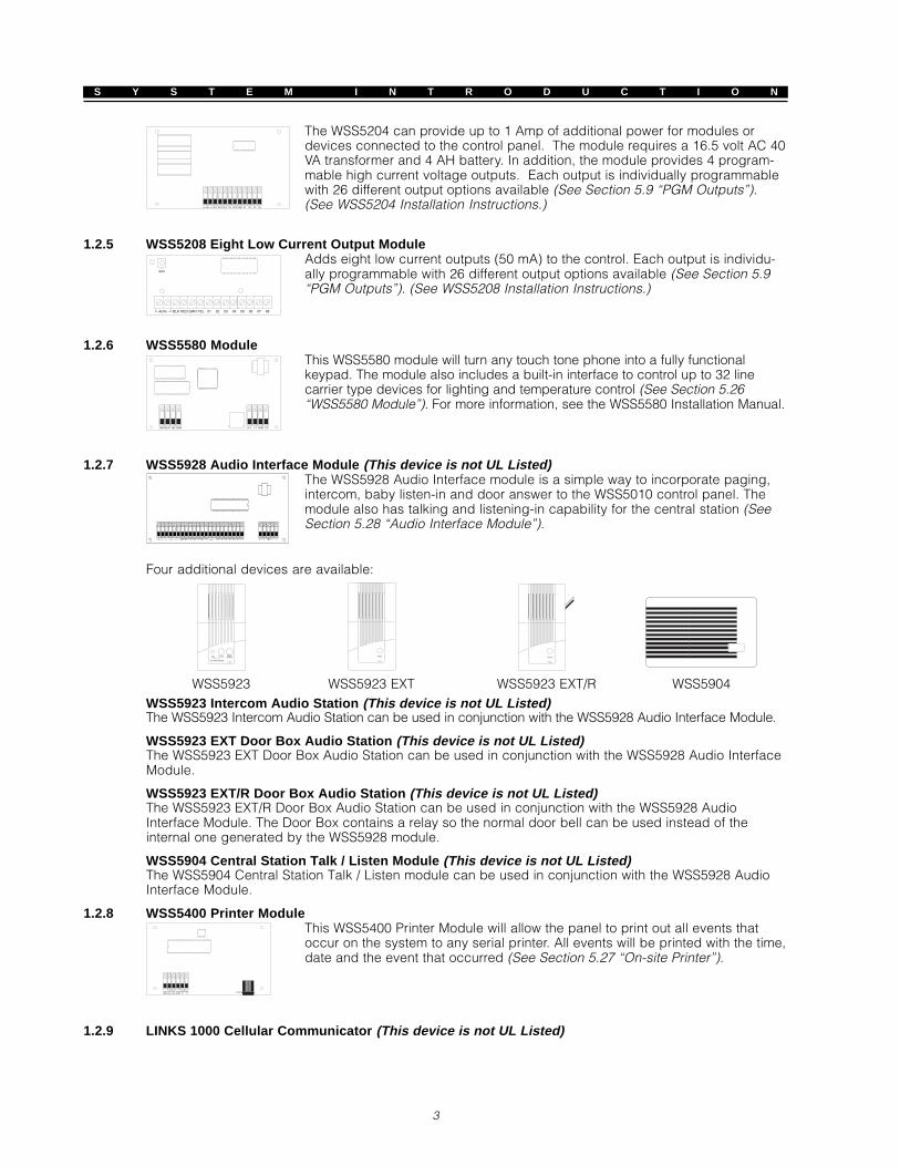
The WSS5204 can provide up to 1 Amp of additional power for modules ordevices connected to the control panel. The module requires a 16.5 volt AC 40VA transformer and 4 AH battery. In addition, the module provides 4 program-mable high current voltage outputs. Each output is individually programmablewith 26 different output options available (See Section 5.9 “PGM Outputs”).(See WSS5204 Installation Instructions.)
1.2.5 WSS5208 Eight Low Current Output ModuleAdds eight low current outputs (50 mA) to the control. Each output is individu-ally programmable with 26 different output options available (See Section 5.9“PGM Outputs”). (See WSS5208 Installation Instructions.)
1.2.6 WSS5580 ModuleThis WSS5580 module will turn any touch tone phone into a fully functionalkeypad. The module also includes a built-in interface to control up to 32 linecarrier type devices for lighting and temperature control (See Section 5.26“WSS5580 Module”). For more information, see the WSS5580 Installation Manual.
1.2.7 WSS5928 Audio Interface Module (This device is not UL Listed)The WSS5928 Audio Interface module is a simple way to incorporate paging,intercom, baby listen-in and door answer to the WSS5010 control panel. Themodule also has talking and listening-in capability for the central station (SeeSection 5.28 “Audio Interface Module”).
Four additional devices are available:
WSS5923 WSS5923 EXT WSS5923 EXT/R WSS5904WSS5923 Intercom Audio Station (This device is not UL Listed)The WSS5923 Intercom Audio Station can be used in conjunction with the WSS5928 Audio Interface Module.
WSS5923 EXT Door Box Audio Station (This device is not UL Listed)The WSS5923 EXT Door Box Audio Station can be used in conjunction with the WSS5928 Audio InterfaceModule.
WSS5923 EXT/R Door Box Audio Station (This device is not UL Listed)The WSS5923 EXT/R Door Box Audio Station can be used in conjunction with the WSS5928 AudioInterface Module. The Door Box contains a relay so the normal door bell can be used instead of theinternal one generated by the WSS5928 module.
WSS5904 Central Station Talk / Listen Module (This device is not UL Listed)The WSS5904 Central Station Talk / Listen module can be used in conjunction with the WSS5928 AudioInterface Module.
1.2.8 WSS5400 Printer ModuleThis WSS5400 Printer Module will allow the panel to print out all events thatoccur on the system to any serial printer. All events will be printed with the time,date and the event that occurred (See Section 5.27 “On-site Printer”).
1.2.9 LINKS 1000 Cellular Communicator (This device is not UL Listed)

S Y S T E M I N T R O D U C T I O N
4
The LINKS 1000 Cellular Communicator provides an efficient, cost-effectivemethod for adding cellular back up. The unit comes in its own cabinet withantenna and requires a separate battery and transformer (See Section 5.24“LINKS 1000 cellular communicator”).
1.2.10 CabinetsSeveral different cabinets are available for the WSS5010 modules:
WSS5002C CabinetCabinet to house the WSS5010 main control panel and also the WSS5204 Power Supply Output Module.Dimensions 213mm x 235mm x 78mm / 8.4” x 9.25” x 3” approximately.
WSS5004C CabinetCabinet to house the WSS5580 Module and WSS5400 Printer Module. Dimensions 229mm x 178mm x65mm / 9” x 7” x 2.6” approximately.
WSS5001C CabinetCabinet to house the WSS5108 Zone Expander Module and the WSS5208 Eight Low Current OutputModule. Dimensions 153mm x 122mm x 38mm / 6” x 4.8” x 1.5” approximately.
WSS5001CP CabinetPlastic cabinet to house the WSS5108 Zone Expander Module, WSS5132-RS Wireless Receiver Moduleand the WSS5208 Eight Low Current Output Module. Dimensions 146mm x 105mm x 25.5mm / 5.75” x4.2” x 1” approximately.
WSS5132C CabinetCabinet to house the WSS5132-RS Wireless Receiver Module. Dimensions 165mm x 143mm x 38mm /6.5” x 5.625” x 1.5” approximately.
CMC-1 Attack Resistant EnclosureListed enclosure for local installations where attack resistance is required. Dimensions 288mm x 298mmx 78mm / 11.3” x 11.7” x 3” approximately.
1.2.11 BackplatesThere are two different backplates available for keypads to locate an Audio Station next to the keypad:
WSS55BP1 BackplateThis backplate is to be used when an Audio Station is to be located next toa keypad. Dimensions 208mm x 115mm x 18mm / 8.2” x 4.5” x 0.25”approximately.
WSS55BP2 BackplateThis backplate is to be used when an Audio Station is to be located nextto a keypad. In addition the backplate will allow you to mount a WSS5108Zone Expander Module or the WSS5208 Eight Low Current OutputModule. Dimensions 208mm x 115mm x 18mm / 8.2” x 4.5” x 0.7”approximately.
1.3 Out of the BoxYou should find the following equipment included in your system. Verify each of the components is included:• one WSS5010 main control cabinet (WSS5002C)• one WSS5010 main control circuit board• one Installation Manual• one hardware pack consisting of:
- 5 plastic circuit board standoffs - 16 5600 ohm (5.6K) resistors- 1 2200 ohm (2.2K) resistor - 1 1000 ohm (1K) resistor- 16V 40VA transformer - ULF siren- RJ-31X telephone block and cord - Battery, 12V, 4 Ah
Note: In order to complete the installation, a keypad(s) must also be used.

Getting StartedS E C T I O N 2
5
The following sections provide a complete description of how to wire and configure devices and zones.
2.1 Installation StepsThe following steps are provided to assist with the installation of the panel. It is suggested that you readover this section briefly to get an overall understanding of the order of installation. Once this is donecarefully work through each step. Working from this plan will help reduce problems and reduce theoverall installation time required.
Step 1 Create a LayoutDraw a rough sketch of the building and include all alarm detection devices, zone expanders, keypadsand all other modules that are required.
Step 2 Mounting the PanelLocate the panel in a dry area, preferably located near an unswitched AC power source and the incomingtelephone line. Before attaching the cabinet to the wall be sure to press the five circuit boardmounting studs into the cabinet from the back.
Complete all wiring before applying AC or connecting the battery .....
Step 3 Wiring the Keybus (Section 2.3)Wire the Keybus to each of the modules following the guidelines provided.
Step 4 Assigning Zones to Zone Expanders (Section 2.5)If zone expander modules are being used the modules must be configured so the panel knows whichzones are assigned to each expander. Follow the guideline provided to assign zones to expanders.
Step 5 Zone Wiring (Section 2.9)Power down the control panel and complete all zone wiring. Follow the guidelines provided in Section 2.9to connect zones using normally closed loops, single EOL resistor, double EOL resistors, Fire zones andKeyswitch Arming zones.
Step 6 Completing WiringComplete all other wiring including bells or sirens, phone line connections, ground connections or anyother wiring necessary. Follow the guidelines provided in Section 2.2 “Terminal Descriptions”.
Step 7 Power up the ControlOnce all zone wiring and Keybus wiring is complete, power up the control panel.
The panel will not power up if only the battery is connected.
Step 8 Keypad Assignment (Section 2.6)Keypads must be assigned to different slots to be properly supervised. Follow the guideline provided inSection 2.6 to assign keypads.
Step 9 Enabling Supervision (Section 2.7)After all modules have been wired to the Keybus, supervision must be enabled. Once supervision isenabled, the panel will be able to indicate module communication faults. Follow the guidelines providedin Section 2.7.
Step 10 Programming the System (Sections 4 and 5)Section 4.0 provides a complete description of how to program the panel. Section 5.0 contains completedescriptions of the various programmable features, what options are available and how the options function.The Programming Work Sheets should be filled out completely before attempting to program the system.
Step 11 Testing the SystemTest the panel completely to ensure that all features and functions are operating as programmed.

G E T T I N G S T A R T E D
6
2.2 Terminal DescriptionsAC Terminals - ACThe panel requires a 16.5 volt, 40 VA transformer. Connect the transformer to an unswitched AC sourceand connect the transformer to these terminals.
Do not connect the transformer until all other wiring is complete .....
Battery ConnectionThe battery is used to provide back up power in the event of an AC power failure and to provideadditional current when the panel demands exceed the power output of the transformer, such as whenthe panel is in alarm.
Do not connect the battery until all other wiring is complete .
Connect the RED battery lead to the positive of the battery, the BLACK battery lead to the negative.
Auxiliary Power Terminals - AUX+ and GNDThese terminals provide up to 500 mA of additional current at 12 VDC (rated 11.6 - 12.6 V DC for UL residentialapplications) for devices requiring power. Connect the positive side of any device requiring power to theAUX+ terminal, the negative side to GND. The AUX output is protected; if too much current is drawn fromthese terminals (wiring short) the panel will temporarily shut off the output, until the problem is corrected.
Bell Output Terminals - BELL+ and BELL-These terminals provide up to 3 Amps of current at 12 VDC (rated 11.6 - 12.6 V DC for UL residentialapplications) (with stand-by battery; 700 mA continuous) for powering bells, sirens, strobes or otherwarning type equipment. Connect the positive side of any alarm warning device to BELL+, the negativeside to BELL–. The BELL output is protected; if too much current is drawn from these terminals (wiringshort) the BELL fuse will open.The Bell output is supervised. If no alarm warning device is being used connect a 1000 ohm resistoracross BELL+ and BELL– to prevent the panel from displaying a trouble condition (See Section 3.4 “[ ]Commands, [ ] [2]”). If an alarm warning device is being used, connect the 1000 ohm resistor at the endof the line across the last device.
Keybus Terminals - RED, BLK, YEL, GRNThe Keybus is used by the panel to communicate with modules and by modules to communicate with thepanel. Each module has four Keybus terminals that must be connected to the four Keybus terminals onthe panel. For more information, see Section 2.3 “Keybus Operation and Wiring”.
Programmable Outputs - PGM1 and PGM2Each PGM output is an open collector switch to ground. That is, when the PGM output is activated by thepanel the terminal will switch to ground.PGM1 can sink up to 50 mA of current to activate LEDs or a small buzzer. Connect the positive side of theLED or buzzer to AUX+, the negative side to PGM1. If more than 50 mA of current is required a relay mustbe used. Refer to the following diagram:
PGM2 operates similar to PGM1.
Zone Input Terminals - Z1 to Z8Each detection device must be connected to a zone on the control. It is suggested that each zone haveone detection device however it is possible to wire multiple detection devices to the same zone.For zone wiring specifics, see Section 2.9 “Zone Wiring” .

G E T T I N G S T A R T E D
7
Telephone Connection Terminals - TIP, RING, T-1, R-1If a telephone line is required for central station communication or downloading connect an RJ-31X jack inthe following manner:• RING - Red Wire ........ Incoming line from • R-1 - Grey Wire .......... Outgoing line to• TIP - Green Wire telephone company • T-1 - Brown Wire house telephone(s)
Ensure the plugs and jacks meet the dimension, tolerance and metallic plating requirementsof 47 C.F.R. Part 68, SubPart F .....For proper operation there must be no other telephone equipment connected between thecontrol panel and the telephone company facilities .....
2.3 Keybus Operation and WiringThe Keybus is used by the panel to communicate with all modules connected and by the modules to talk tothe panel. The RED and BLK terminals are used to provide power while YEL and GRN are clock and data.
The 4 Keybus terminals of the panel must be connected to the 4 Keybus terminals or wires ofall modules.
The following conditions apply:• Keybus should be run in minimum 22 gauge quad (0.5mm), two pair twist preferred• the modules can be home run to the panel, connected in series or can be T-tapped• any module can be connected anywhere along the Keybus, you do not need a separate Keybus wire
run for keypads, zone expanders etc.• no module can be more than 1,000'/330m (in wire length) from the panel• shielded wire is not necessary unless wires are run in an area that may present excessive RF noise or
interferenceExample of Keybus Wiring
B
C
APANEL500’
500’
150’
150’
B
C
APANEL500’
500’
150’
150’
NOTE: Module (A) is wired correctly as it is within 1,000'/330m of the panel, in wire distance.Module (B) is wired correctly as it is within 1,000'/330m of the panel, in wire distanceModule (C) is NOT wired correctly as it is further than 1,000'/330m from the panel, in wire distance.
G E T T I N G S T A R T E D
8
2.4 Current Ratings - Modules and AccessoriesIn order for the WSS5010 system to operate properly, the power output capabilities of the main controland expansion devices must not be exceeded. Use the data presented below to ensure that no part ofthe system is overloaded and cannot function properly.
System Outputs (all 12 V DC)• WSS5010
+AUX: 500 mA. Includes one keypad. Subtract for each additional keypad, expansion module andaccessory connected to VAUX or Keybus.
BELL: 700 mA. Continuous Rating.3.0 A. Short Term. Available only with stand-by battery connected.
• WSS5204VAUX: 1.0 A. Continuous Rating. Subtract for each device connected.
3.0 A. Short Term. Available only with stand-by battery connected.• WSS5208
VAUX: 250 mA. Subtract for each device connected. Subtract the total load on this terminal from theWSS5010 VAUX/Keybus output.
• WSS5108VAUX: 100 mA. Subtract for each device connected. Subtract the total load on this terminal from the
WSS5010 VAUX/Keybus output.
WSS5010 Device Ratings (@ 12 V DC)• WSS5500 LCD Keypad: 50 mA; 100mA max. • WSS5580 Module: 150 mA• WSS5508 LED Keypad: 45 mA; 70mA max. • WSS5928 Audio Interface Module: 65 mA• WSS5108 Zone Module: 35 mA • WSS5923 Intercom Audio Station: 20 mA• WSS5204 Output Module: 20 mA • WSS5923 EXT Door Box Audio Station: 20 mA• WSS5208 Output Module: 50 mA • WSS5923 EXT/R Door Box Audio Station: 35 mA• WSS5132-RS Wireless Module: 125 mA • WSS5400 Serial Printer Module: 62 mA
Other DevicesRead the manufacturer’s literature carefully to determine the maximum current requirement (duringactivation or alarm) and use this value for loading calculations. Do not allow connected devices to exceedthe system capabilities during any possible operational mode.
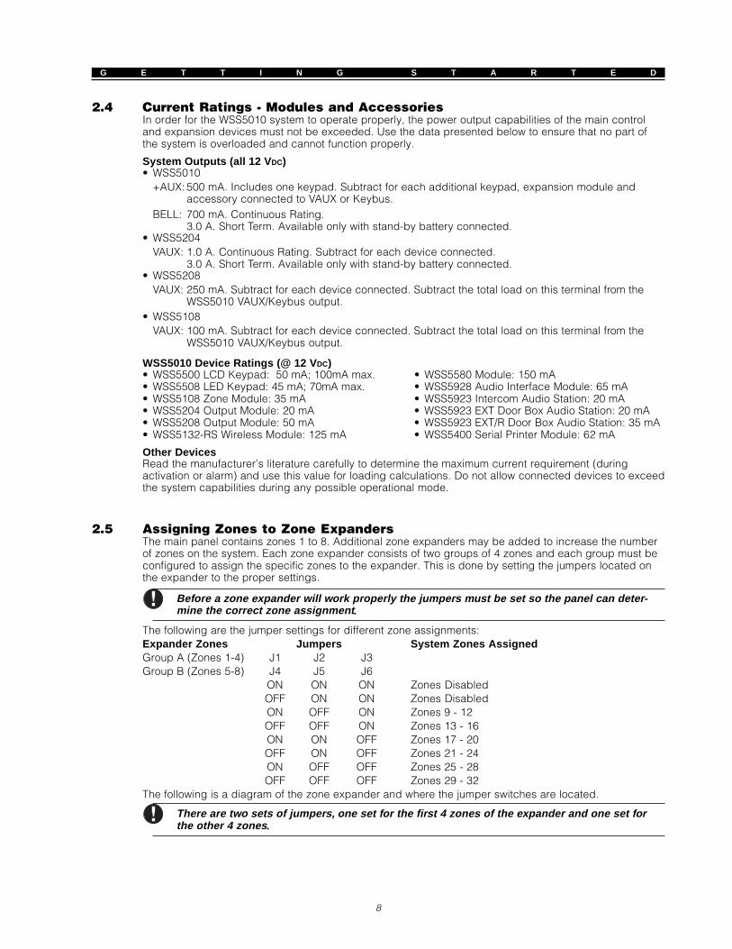
2.5 Assigning Zones to Zone ExpandersThe main panel contains zones 1 to 8. Additional zone expanders may be added to increase the numberof zones on the system. Each zone expander consists of two groups of 4 zones and each group must beconfigured to assign the specific zones to the expander. This is done by setting the jumpers located onthe expander to the proper settings.
Before a zone expander will work properly the jumpers must be set so the panel can deter-mine the correct zone assignment .....
The following are the jumper settings for different zone assignments:Expander Zones Jumpers System Zones AssignedGroup A (Zones 1-4) J1 J2 J3Group B (Zones 5-8) J4 J5 J6
ON ON ON Zones DisabledOFF ON ON Zones DisabledON OFF ON Zones 9 - 12OFF OFF ON Zones 13 - 16ON ON OFF Zones 17 - 20OFF ON OFF Zones 21 - 24ON OFF OFF Zones 25 - 28OFF OFF OFF Zones 29 - 32
The following is a diagram of the zone expander and where the jumper switches are located.
There are two sets of jumpers, one set for the first 4 zones of the expander and one set forthe other 4 zones .....
G E T T I N G S T A R T E D
9
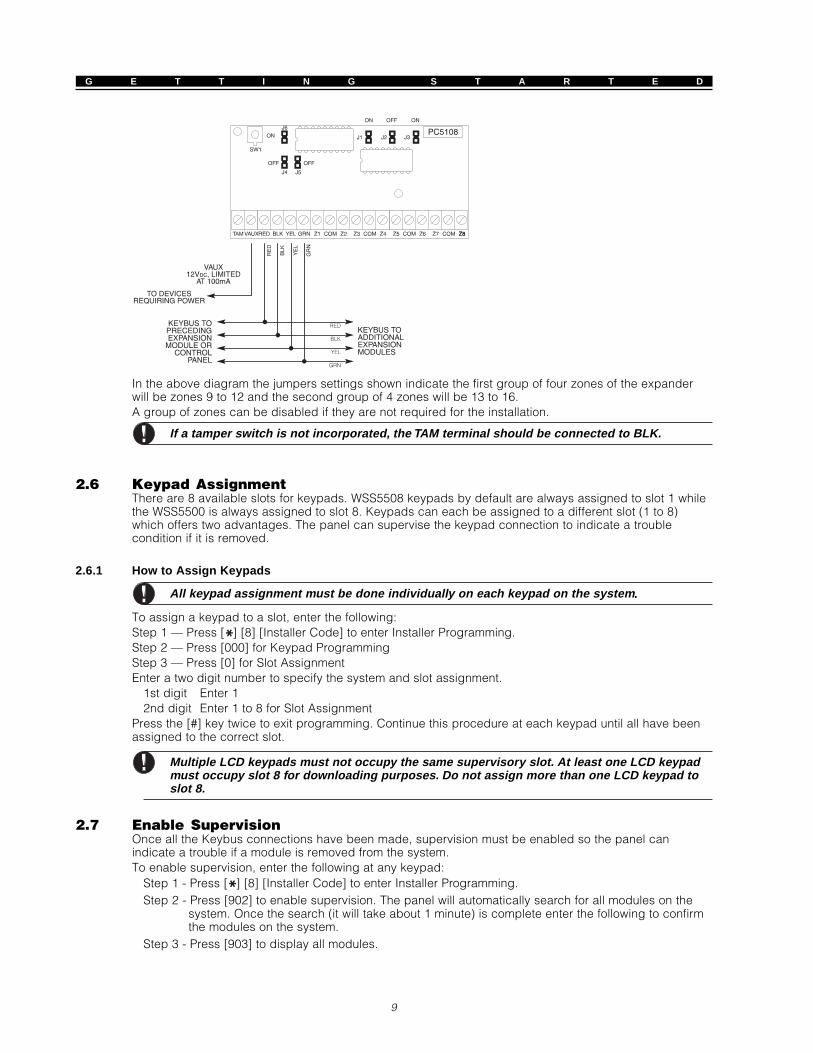
In the above diagram the jumpers settings shown indicate the first group of four zones of the expanderwill be zones 9 to 12 and the second group of 4 zones will be 13 to 16.A group of zones can be disabled if they are not required for the installation.
If a tamper switch is not incorporated, the TAM terminal should be connected to BLK.
2.6 Keypad AssignmentThere are 8 available slots for keypads. WSS5508 keypads by default are always assigned to slot 1 whilethe WSS5500 is always assigned to slot 8. Keypads can each be assigned to a different slot (1 to 8)which offers two advantages. The panel can supervise the keypad connection to indicate a troublecondition if it is removed.
2.6.1 How to Assign Keypads
All keypad assignment must be done individually on each keypad on the system .....
To assign a keypad to a slot, enter the following:Step 1 — Press [ ] [8] [Installer Code] to enter Installer Programming.Step 2 — Press [000] for Keypad ProgrammingStep 3 — Press [0] for Slot AssignmentEnter a two digit number to specify the system and slot assignment.
1st digit Enter 12nd digit Enter 1 to 8 for Slot Assignment
Press the [#] key twice to exit programming. Continue this procedure at each keypad until all have beenassigned to the correct slot.
Multiple LCD keypads must not occupy the same supervisory slot. At least one LCD keypadmust occupy slot 8 for downloading purposes. Do not assign more than one LCD keypad toslot 8.
2.7 Enable SupervisionOnce all the Keybus connections have been made, supervision must be enabled so the panel canindicate a trouble if a module is removed from the system.To enable supervision, enter the following at any keypad:
Step 1 - Press [ ] [8] [Installer Code] to enter Installer Programming.Step 2 - Press [902] to enable supervision. The panel will automatically search for all modules on the
system. Once the search (it will take about 1 minute) is complete enter the following to confirmthe modules on the system.
Step 3 - Press [903] to display all modules.

G E T T I N G S T A R T E D
10
Zone lights will be turned on according to what modules the panel has found on the system. The LCDkeypad will allow you to scroll through the modules. Refer to the following chart:
Light [1] ....... Keypad 1 present Light [13] ....... Zones 25 to 28 presentLight [2] ....... Keypad 2 present Light [14] ....... Zones 29 to 32 presentLight [3] ....... Keypad 3 present Light [15] ....... N/A (not used)Light [4] ....... Keypad 4 present Light [16] ....... N/A (not used)Light [5] ....... Keypad 5 present Light [17] ....... Module WSS5132-RS presentLight [6] ....... Keypad 6 present Light [18] ....... Module WSS5208 presentLight [7] ....... Keypad 7 present Light [19] ....... Module WSS5204 presentLight [8] ....... Keypad 8 present Light [20] ....... Module WSS5400 presentLight [9] ....... Zones 9 to 12 present Light [21] ....... Module WSS5928 presentLight [10] ....... Zones 13 to 16 present Light [22] ....... N/ALight [11] ....... Zones 17 to 20 present Light [23] ....... N/ALight [12] ....... Zones 21 to 24 present Light [24] ....... WSS5580 module present
If a module is connected but does not show as being present, it may be due to any of the followingreasons:• it is not connected to the Keybus• if there is a Keybus wiring problem• if the module is more than 1,000'/330m from the panel• if the module does not have enough power• if the WSS5132-RS does not have any devices added
2.8 Removing ModulesIf a module is no longer required on the system the panel must be told to no longer supervise the module. Todo this remove the module from the Keybus and perform the Enable supervision function again (See Section2.7 “Enable Supervision”). The panel will see the module has been removed and will no longer supervise it.
2.9 Zone WiringThere are several different ways in which zones may be wired, depending on the programming optionsselected.
Any zone defined as Fire, 24 Hour Links Supervisory and Links Answer (See Section 5.1“Zone Definitions”) will automatically require a single End of Line (EOL) resistor regardlessof which type of zone wiring supervision is selected .When reconfiguring the zone supervision from a non-default setting, such as DEOL to EOL/NC to DEOL/disabling zones 1-8 while open or in trouble, the system should be powereddown completely and powered up again.
2.9.1 Normally Closed (NC) LoopsWire all zones according to the following diagrams:
2 NORMALLY CLOSEDCONTACTS WITHNO END OF LINE
RESISTOR
ANY ZTERMINAL
ANY COMTERMINAL
NORMALLY CLOSEDCONTACT;
NO END OF LINERESISTOR
ANY ZTERMINAL
ANY COMTERMINAL
This option can only be selected if Normally Closed (NC) detection devices or contacts arebeing used .
G E T T I N G S T A R T E D
11
2.9.2 Single End Of Line (EOL) ResistorsWire all zones according to the following diagrams:
NORMALLY CLOSEDCONTACT WITH
5600 Ω END OF LINERESISTOR
ANY ZTERMINAL
ANY COMTERMINAL
NORMALLY OPENCONTACTS WITH
5600 Ω END OF LINERESISTOR
ANY ZTERMINAL
ANY COMTERMINAL
ANY ZTERMINAL
ANY COMTERMINAL
2 NORMALLY OPENCONTACT AND
2 NORMALLY CLOSEDCONTACT WITH
5600 Ω END OF LINERESISTOR
1 NORMALLY OPENCONTACT AND
1 NORMALLY CLOSEDCONTACT WITH
5600 Ω END OF LINERESISTOR
ANY ZTERMINAL
ANY COMTERMINAL
This option can be selected if either Normally Closed (NC) or Normally Open (NO) detectiondevices or contacts are being used .
2.9.3 Double End of Line (DEOL) ResistorsDouble EOL loops allow the panel to determine if the zone is in alarm, tampered or faulted. Wire the zonesaccording to the following diagram:
ANY ZTERMINAL
ANY COMTERMINAL
ALARMCONTACT
DOUBLE EOL CIRCUIT1 NORMALLY CLOSED
CONTACT WITH5600Ω END OF LINE
RESISTORS
This option can be selected only if Normally Closed (NC) detection devices or contacts arebeing used .Only one NC contact can be connected to each zone. The connection of multiple detectiondevices or contacts on one loop is not allowed .
The following chart shows the status of the zone under certain conditions:Loop Resistance ................................... Loop Status5600Ω (contact closed) ........................ Secure11200Ω (contact open) ........................ Violated0Ω (shorted wire, loop shorted) ........... FaultInfinite (broken wire, loop open) ........... Tamper
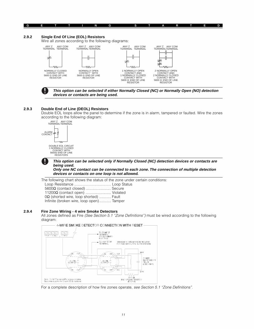
2.9.4 Fire Zone Wiring - 4 wire Smoke DetectorsAll zones defined as Fire (See Section 5.1 “Zone Definitions”) must be wired according to the followingdiagram:
For a complete description of how fire zones operate, see Section 5.1 “Zone Definitions”.

G E T T I N G S T A R T E D
12
2.9.5 Fire Zone Wiring - 2 wire Smoke DetectorsIf PGM2 has been programmed for 2 Wire Smoke Detector connection (See Section 5.9 “PGM Output”),the detectors must be wired according to the following diagram:
+
Ω
+
-
For a complete description of how fire zones operate, see Section 5.1 “Zone Definitions”.
If PGM2 is programmed for 2 wire smoke support, Jumper J1 on the main board must be removed.
2.9.6 LINKS Supervisory (Shall not be used on UL certificated systems)If the LINKS 1000 cellular communicator is being used a zone may be configured for LINKS Supervisory(See Section 5.1 “Zone Definitions”). If the LINKS 1000 experiences a trouble it will violate the zone,causing the panel to report the event to central station.The zone programmed as LINKS Supervisory ALWAYS requires a single EOL resistor (5.6K) and must bewired according to the following diagram:
2.9.7 LINKS Answer (Shall not be used on UL certificated systems)If the LINKS 1000 cellular communicator is being used a zone may be configured for LINKS Answer toallow downloading to be performed in the event of phone line failure.When the LINKS receives a phone call it will activate the RING terminal on the LINKS circuit board. Thisterminal can be used to violate a zone programmed as LINKS Answer (See Section 5.1 “ZoneDefinitions”), causing the panel to seize the phone line and begin communication with the downloadingcomputer.The zone programmed as LINKS Answer ALWAYS requires a single EOL resistor (5.6K) and must bewired according to the following diagram:
Do not make this connection without direction from Westar Technical Support.
Keypad CommandsS E C T I O N 3
13
All keypads provide complete information and control of the alarm panel. The panel can be completely programmedvia any keypad on the system. LED keypads provide function indicator lights and individual zone indicator lights forthe alarm circuits. The LCD keypad provides function indicator lights and word descriptions for zone status.
The following sections describe how to arm, disarm and perform other keypad functions.
3.1 Access CodesThe panel has a total of 37 Access Codes available.
Access Codes [01] to [32] .. User Codes 1 to 32Access Code [33] .............. Duress CodeAccess Code [34] .............. Duress CodeAccess Code [40] .............. System Master CodeAccess Code [41] .............. Master CodeAccess Code [42] .............. Master Code
System Master CodeThe System Master Code Not ChangeableSystem Master Code Not ChangeableSystem Master Code Not ChangeableSystem Master Code Not ChangeableSystem Master Code Not Changeable option can be used to lock in the code. This will prevent theuser from being able to change the System Master Code. If they attempt to change the code the keypadwill sound a long error beep. The System Master Code can be used to arm or disarm the system andperform any keypad function.If the code is lost it can be reprogrammed through Installer Programming.
System Master Code Not Changeable ......... Section [015], Option [4]
System Master Code ..................................... Section [007]
Master CodesBy default the Master Codes are not programmed. They must be programmed by the System Master Code.Once programmed, a Master Code can perform the same basic system functions as the System MasterCode. In addition, it can be used to program the 32 User Codes and 2 Duress Codes on the system.
Duress CodesBy default Duress Codes are not programmed. They must be programmed by the System Master Code orMaster Code. Once programmed if the Duress Code is used, the panel will activate a silent Duress alarm(See Section 5.7 “Communicator - Reporting Codes”).
User CodesBy default the 32 User Codes are not programmed. They must be programmed by the System MasterCode or Master Code. Once programmed the User Code can be used to arm or disarm the system. Inaddition, each User Code can be enabled or disabled for bypass ability (See Section 3.4 “[ ]Commands, [ ] [1] Zone Bypass”) and for accessing the system by the WSS5580.
3.2 ArmingThe system cannot be armed unless the ‘Ready’ light is on. If the ‘Ready’ light is not on make sure allprotected doors and windows are secure and stop movement in areas covered by motion detectors.If the ‘Ready’ light is on, press the ‘Stay’ or ‘Away’ key for 2 seconds.The Arming Keys Require Access Code option can be used so that an access code is needed afterusing the STAY/AWAY arming keys. This would be used in conjunction with Closings Enabled in theDialing Options.....
Arming Keys Require Access Code .............. Section [015], Option [3]
Closings Enabled .......................................... Section [360], Option [6]
3.2.1 Stay ArmingThe system will be armed with all interior Stay/Away type zones Bypassed so that users can remain in thepremises while armed. The perimeter zones will be armed.
3.2.2 Away ArmingThe system will be armed with all interior Stay/Away type zones Active. If motion is detected on the Stay/Away type zones, the alarm sequence will begin.

K E Y P A D C O M M A N D S
14
3.3 DisarmingTo disarm the panel enter the premises through the designated entry/exit door. The keypad will emit asteady beep to warn that you must disarm the system. During the last 10 seconds of entry delay the panelwill pulse the keypad beeper on and off rapidly to warn the entry delay is about to expire. Enter a validAccess Code at the keypad. If an error is made press the Clear function key or the [#] key, then enter thecode again. When a correct code is entered the keypad will turn off the ‘Armed’ light and stop the keypadbuzzer. If an alarm occurred while the panel was armed the ‘Memory’ light and the zones which causedthe alarm will be flashing. Press the [#] key to return the keypad to the Ready state.
3.4 [ ] Commands[ ] [1] Zone Bypass/Reactivate Stay/Away Zones
The [ ] [1] keypad command can be used to bypass individual zones. It can be used if the user wants tohave access to an area while the system is armed or to bypass a defective zone (bad contact, damagedwiring) until service can be provided.The system can be armed with a bypassed zone. A bypassed zone will not cause an alarm.Bypass Status Displayed will indicate on the keypads, while armed, that there are zones that have beenmanually bypassed on the system.
Bypass Status Displayed………………………..Section [015] Option [8]
Code Required for Bypass (required for UL Listed systems) is enabled therefore an access code willbe required to enter the Bypass mode. Only user codes with the Bypass attribute enabled will be able tobypass zones (See Section 3.4 “[ ] Commands, [ ] [5]“).
Zones can only be bypassed when the system is disarmed.
To bypass a zone:1. Enter [ ] [1] [Access Code]2. The keypad will flash the ‘Bypass’ light and turn on the zone lights for any zones already bypassed.3. Enter the 2 digit zone number to bypass the zone.4. The keypad will turn on the zone light.5. Press [#].All zones that were lit when the [#] key was pressed are now bypassed. The ‘Bypass’ light will be onsteady to indicate zones are bypassed.
To un-bypass a zone:1. Enter [ ] [1] [Access Code].2. The keypad will flash the ‘Bypass’ light and turn on the zone lights for any zones already bypassed.3. Enter the 2 digit zone number to un-bypass the zone.4. The keypad will turn off the zone light.5. Press [#].All zones that were lit when the [#] key was pressed are now bypassed. If no zones were lit, the ‘Bypass’light will be off and no zones will be bypassed.
When the system is disarmed all manually bypassed zones will be un-bypassed.
Reactivate InteriorIf the system is armed in the Stay mode (See Section 3.2 “Arming”), the [ ] [1] command can be used toreactivate the Stay/Away zones.
[ ] [2] Trouble DisplayThe panel constantly monitors itself for several different trouble conditions. If a trouble condition ispresent the ‘Trouble’ light will be on steady and all keypads will beep twice every 10 seconds.Bell Squawk on Trouble will sound the bell twice every 10 seconds in conjunction with the keypadbuzzer, and will be silenced when a key is pressed on the keypad.
The trouble beep can be silenced by pressing any key on any keypad.
Bell Squawk on Trouble ................................. Section [014], Option [2]

K E Y P A D C O M M A N D S
15
To view trouble conditions:1. Press [ ] [2].2. The keypad will flash the ‘Trouble’ light and light zones to indicate which trouble conditions arepresent.A description of the various troubles are as follows:
Trouble [1] - Service RequiredThis light will be on if any of the following trouble conditions are detected by the control panel; LowBattery, Bell Circuit Trouble, General System Trouble, General System Tamper, General SystemSupervisory, WSS5204 Low Battery and WSS5204 AC Failure.If a ‘Service Required’ trouble is present press [1] to determine the specific trouble present. The followingis a list of the specific ‘Service Required’ trouble conditions:• Light [1] - Low Battery
The main panel backup battery is low. The trouble will be generated if the battery drops below 11.5volts under load and will restore when the battery charges over 12.5 volts.
• Light [2] - Bell Circuit TroubleThe panel will indicate this trouble if the Bell fuse is blown or the panel senses an open condition on thebell circuit (See Section 5.11 “Siren Supervision”).
• Light [3] - General System TroubleThis trouble will be present if the WSS5204 Power Supply module has an AUX failure, WSS5204 Output#1 Trouble, or a printer connected to the WSS5400 Printer module has a fault (off-line).
• Light [4] - General System TamperThis trouble will be indicated if a Tamper Zone violation on any module is detected.
• Light [5] - General System SupervisoryThis trouble will be indicated if the panel loses communication with any module connected to the Keybus(See Section 2.7 “Enable Supervision”). The event buffer will log a detailed description of the event.A Keybus fault will also cause this trouble to be displayed. A Keybus fault will occur if one of the data lines(yellow or green wire) is shorted to ground.
• Light [6] - Not Used• Light [7] - WSS5204 Low Battery
The WSS5204 module has a low backup battery.• Light [8] - WSS5204 AC Failure
The WSS5204 module has lost AC power.
Trouble [2] - AC FailureThis trouble indicates that AC power is no longer being supplied to the control unit. If it is required tocommunicate this to a monitoring station, enable Maintenance Alarms and Maintenance Restorals inSection [360] options [7] and [8] respectively. To inhibit reporting of short duration power outages, adelay can be programmed in section [370].
Trouble [3] - Telephone Line TroubleThe telephone connection to the control unit is continuously monitored. If there is a problem with thetelephone connection, a trouble will be indicated after the delay programmed in section [370]. If thesystem has a LINKS 1000, this trouble can be reported to a monitoring station by enabling MaintenanceAlarms and Maintenance Restorals in Section [361] options [7] and [8] respectively.
Trouble [4] - Failure to Communicate (FTC)If the communicator fails in an attempt to communicate with any of the programmed telephone numbers,this trouble will be generated. If a later attempt is successful, the FTC reporting code, enabled byMaintenance Restorals in Section [360] options [8], will be transmitted along with any other unreportedevents that occurred while the panel was not able to communicate.
Trouble [5] - Zone Fault (including Fire Zone)This trouble will be indicated if any zone on the system is in a trouble condition, i.e. it could not provide analarm to the panel if required to do so. When a trouble condition occurs, the keypad(s) will start to beep.Press [5], while in Trouble mode, to view which zones have a trouble condition. If 2-wire smoke detectorsare being used, a trouble on that zone will be indicated by the “Fire” LED.
Trouble [6] - Zone TamperThis trouble is only generated by zones configured for Double End-of-Line Resistor Supervision orwireless zones. This trouble is generated when a tamper condition is present. When a tamper conditionoccurs, the keypad(s) will start to beep.Press [6], while in Trouble mode, to view which zones have a tamper condition.

K E Y P A D C O M M A N D S
16
Trouble [7] - Zone Low BatteryThis trouble is generated when an RF device reports a low battery condition to the control unit. Press [7]while in Trouble mode to view which RF zones have a low battery. Press [7] to view which One Waykeypad has a low battery and press [7] again to view which wireless key has a low battery.
Trouble [8] - Loss of System TimeThis trouble occurs when the control unit is powered up and the internal clock has not been set. Settingthe time with User Function [ ] [6] [Master Code] [1] will clear this trouble.
[ ] [3] Alarm MemoryThe ‘Memory’ light will be on if any alarm occurred during the last armed period or if an alarm occurredwhile the panel was disarmed (24 hour zones).
To view alarm memory:1.Press [ ] [3].2.The keypad will flash the Memory light and light up zone lights to indicate alarm or tamper conditions
that occurred during or since the last armed period.When the panel is armed the ‘Memory’ light will go out.
If the alarm memory is cleared, the events can be viewed in the event buffer.
[ ] [5] Programming Access CodesThere are 37 Access Codes available. They are as follows:
Access Code [01] to [32] . User Codes 1 to 32Access Code [33] ............. Duress CodeAccess Code [34] ............. Duress CodeAccess Code [40] ............. System Master CodeAccess Code [41] ............. Master CodeAccess Code [42] ............. Master Code
All Access Codes have the ability to arm/disarm the system and activate the PGM Outputs using the[ ][7] [1] [Access Code] and [ ] [7] [2] commands (See Section 3.4 “[ ] Commands, [ ] [7]”).Additional Access Code Attributes are also programmable. Attributes determine what abilities the codewill have. The programmable attributes are as follows:• Pager Communications • Zone Bypassing• Day Zone Reset • Phone Access on WSS5580
User Codes - Access Codes [01] to [32]Each User Code can be programmed to have the ability to bypass zones and access the system throughthe WSS5580.
“Master code” attributes cannot change. By default, each code has the attributes of the codeused to program it.
Duress Codes - Access Codes [33] and [34]When a Duress Code is used to perform any function the panel will report a Duress Reporting Code (SeeSection 5.7 “Communicator - Reporting Codes”).
Master Codes - Access Codes [41] and [42]Master Codes can program additional User Codes and the Duress Codes.
System Master Code - Access Code [40]By default the System Master Code is enabled to perform any keypad function. This code can be used toprogram all User Codes as well as the Master Codes and Duress Codes.If the Master Code Not Changeable option is enabled the System Master Code can only be changedusing Installer Programming.
How to program Access Codes:Programming Access Codes is a two step process. First the Code must be programmed followed by theCode Attributes.1.Enter [ ] [5] [Master Code]. The keypad will flash the ‘Program’ light and turn on the zone light for any
code already programmed.2.Enter the 2 digit number for the code you want to program. The corresponding zone light will flash.3.Enter a 4 digit code. The zone light will turn on steady.4.Continue with steps 2 and 3 until all codes are programmed.
Do not press [ ] or [#] when programming the 4 digit code.When programming Duress Codes or Master Codes no zone light will flash.
After all the Codes have been programmed press the [#] key to return to the Ready mode.

K E Y P A D C O M M A N D S
17
How to program Access Code Attributes:
“Master Code” attributes cannot change. By default, each code has the attributes of the codeused to program it.
1.Enter [ ] [5] [Master Code]. The keypad will flash the ‘Program’ light and turn on the zone light for anycode already programmed.
2.Press [9] to enter the Attribute mode. The keypad will turn on the ‘Ready’ light and turn off the armedlight.
3.Enter the 2 digit number for the code you want to program Attributes for. Zone lights [1] to [4] will be onor off. Refer to the following chart:
Zone Light 1 - ON - Pager Communications enabledZone Light 2 - ON - Day Zone Reset enabledZone Light 3 - ON - enable zone bypassZone Light 4 - ON - Phone Access through WSS5580 enabled
4.Enter [1] to [4] to turn the zone lights ON or OFF.5.Continue with steps 2 and 3 until all code attributes are programmed.After all the codes and attributes have been programmed press the [#] key to exit Access Code Programming.
How to erase Access Code:Select the code to be erased and press [ ].
[ ] [6] User FunctionsThis keypad command can be used to program several different functions. The following are the itemsprogrammable:
[1] - Time and Date[2] - System Test[3] - User Call-Up (Downloading)[4] - [7] For future use
To program User Functions:1.Press [ ] [6] [Master Code]. The keypad will flash the ‘Program’ light.2.Press the number [1] to [7] for the item to be programmed.• [1] - Time and Date
The time and date must be accurate for the Test Transmission function to work properly. In addition theevent buffer time and date stamps all events.- Enter the time: hour and minute, using 24-hour format [HH MM]. (00:00 to 23:59)- Enter the date: month, day and year [MM DD YY].
All entries must be 2 digits. For example, eight o’clock in the morning would be [08] hoursand [00] minutes, and January would be month [01].
• [2] - System TestWhen [2] is pressed the panel will perform the following:- sound the alarm output for two seconds- light all lights on the keypad- sound the keypad buzzer for two seconds- test the main panel battery- send a System Test Reporting code, if programmed (See Section 5.7 “Communicator - ReportingCodes”).
System Test will not activate any Fire outputs.
• [3] - User Call-Up (Downloading)When [3] is pressed the panel will call the downloading computer (See Section 5.8 “Downloading”).
• [4] - [7] For future use
Additional Features are available using on the LCD keypad. These features do not havenumbers assigned. Use the arrow keys (< >) to scroll through the [ ] [6] menu and press the[ ] key to select the following commands.
View Event BufferThe 128 Event Buffer can be viewed through any LCD keypad (See Section 5.15.1 “Viewing the EventBuffer Through the LCD Keypad”).
Brightness ControlWhen this option is selected the keypad will allow you to scroll through 10 different backlight leveloptions. Use the arrow keys (<>) to scroll to the desired backlight level and press the [#] key to exit.

K E Y P A D C O M M A N D S
18
Contrast ControlWhen this option is selected the keypad will allow you to scroll through 10 different contrast level options.Use the arrow keys (<>) to scroll to the desired contrast level and press the [#] key to exit.
Keypad Buzzer ControlWhen this option is selected the keypad will allow you to scroll through 21 different keypad sounder toneoptions. Use the arrow keys (<>) to scroll to the desired keypad beeper level and press the [#] key toexit. This function can be achieved on LED keypads by holding the [ ] key.
[ ] [7] Output FunctionsTwo Output Functions can be performed at a keypad. They are Utility Output and Smoke Detector Reset.
To activate Utility Output:Press [ ] [7] [1] [Access Code]. The panel will activate all PGM Outputs for 5 seconds programmed asUtility Output (see Section 5.9 “PGM Outputs”).
To activate Smoke Detector Reset:Press [ ] [7] [2]. The panel will activate all PGM Outputs for 5 seconds programmed as Sensor Reset.This command will also reset two wire smoke detectors connected to PGM2 programmed as Two WireSmoke Support (see Section 5.9 “PGM Outputs”).
[ ] [8] Installer ProgrammingEnter [ ] [8] followed by the 6-digit Installer Code to enter Installer Programming (see Section 4.0 “How toProgram”).
[ ] [9] Arming Without Entry DelayWhen the system is armed with the [ ] [9] command the panel will remove the entry delay from thesystem. After the exit delay, Delay 1 and Delay 2 type zones will be instant. If the panel is armed in theStay mode, all Stay/Away zones will remain bypassed (see Section 5.1 “Zone Definitions”).[ ] [9] must be entered after the ‘Stay’ or ‘Away’ function key has been pressed.
Master Code Not Changeable option ........... Section [015], Option [4]
Quick Exit Enable .......................................... Section [015], Option [2]
3.5 Function KeysThere are 5 function keys on the WSS5010 keypads labelled Stay, Away, Chime, Clear and Exit. The operationof these keys is described below. The function is activated by pressing and holding the key for 2 seconds.
“Stay” - Stay ArmArms the system. All Stay/Away type zones will be automatically bypassed. Delay type zones will provideentry and exit delay.
“Away” - Away ArmArms the system. All Stay/Away type zones will be active at the end of the exit delay. Delay type zoneswill provide entry and exit delay.
“Chime” - Door Chime On/OffPressing the key will toggle the Door Chime feature ON or OFF. One solid beep means the feature hasbeen disabled, three short beeps means it has been enabled.
“Clear” - Clears Alarm MemoryPressing this key will cause the panel to clear any alarm memory that the panel may have without havingto arm and disarm again. Pressing this key will also clear partially entered access codes, or return thekeypad to the base menu from [ ] functions.
“Exit” - Activate Quick ExitPressing this key will cause the panel to activate the Quick Exit function. If the Quick Exit Enabled option isenabled, the panel will provide a two minute window to exit. During this time the panel will ignore any activation ofa delay type zone. When the delay zone is secured the panel will end the two minute time period. If a seconddelay zone is tripped, or if the zone is not restored after two minutes, the panel will start entry delay.
Quick Exit is not designed to extend the standard exit delay.

How to ProgramS E C T I O N 4
19
The following section of the manual describes how to enter Installer Programming and how to program the varioussections.
It is extremely important that you read the following section of the manual to completely understandhow to program the panel.
4.1 How to Enter Installer ProgrammingInstaller Programming is used to program all communicator and panel options.
LED KeypadStep 1 From any keypad enter [ ] [8] [Installer Code].
• The ‘Program’ light will flash to indicate you are in programming• The ‘Armed’ light will turn on to indicate the panel is waiting for the 3 digit Section number to
programStep 2 Enter the 3 digit Section number you want to program.
• The Armed light will turn off• The Ready light will turn on to indicate the panel is ready for the information for the selected
Section
If the 3 digit section number entered is not valid or the module that pertains to the Section isnot present the keypad will sound a 2 second beep or error tone.
LCD KeypadStep 1 From any keypad enter [ ] [8] [Installer Code].
The Keypad will display ‘Enter Section’ followed by three dashes.Step 2 Enter the 3 digit Section number you want to program.
The keypad will now display information for the section entered.
Installer Code ................................................ Section [006]
4.2 Programming Decimal DataWhen the Ready light is ON the panel is waiting for the information to be programmed for the selectedSection. Enter the information written in the boxes for the Section found in the Programming Worksheets.If a digit is entered for each program box in a Section the panel will automatically exit from the Section. Itwill turn OFF the Ready light and turn the Armed light back ON.You can also press the [#] key to exit a Section before entering data for every box. This is handy if youonly need to change the first few program boxes. All other locations in the Section will remain unchanged.If the [#] key is pressed the panel will turn OFF the Ready light, turn ON the Armed light and exit you fromthe Section.
4.3 Programming HEX DataOn occasion, hexadecimal (HEX) digits may be required. To program a HEX digit press the [ ] key. Thepanel will enter HEX programming and Ready light will begin to flash.The following table indicates which number should be pressed to enter the corresponding HEX digit:1 = A 2 = B 3 = C 4 = D 5 = E 6 = FAfter the correct HEX digit is entered the ‘Ready’ light will continue to flash. If another HEX digit isrequired press the corresponding number. If a decimal digit is required press the [ ] key again. The‘Ready’ light will turn on solid and the panel will return to regular decimal programming.
It is important to watch the ‘Ready’ light. If the light is flashing any number you enter will beprogrammed as the HEX equivalent.

H O W T O P R O G R A M
20
Example: To enter ‘C1’ for the first 2 digits of the Account Code, enter [ ] [3] [ ] [1].[ ] to enter Hexadecimal mode (‘Ready’ light flashes)[3] to enter C[ ] to return to decimal mode (‘Ready’ light is solid)[1] to enter 1If you enter information into a section and make a mistake, press the [#] key to exit the section. Select thatsection again and re-enter the information correctly.
4.4 Programming Toggle Option SectionsSome Sections contain several toggle options. The panel will use zone lights 1 through 8 to indicate if thedifferent options are enabled or disabled. Refer to the Programming Worksheets to determine what eachoption represents and whether the light should be ON or OFF for your application.Press the number corresponding to the option to toggle the light ON or OFF.Once all the toggle options have been selected correctly press the [#] key to exit the Section and savethe changes. The panel will turn off the Ready light and turn on the Armed light.
4.5 Viewing Programming4.5.1 LED Keypad
Any program Section can be viewed through the keypad. When a Section is entered the keypad willimmediately display the first digit of information programmed in that Section.The keypad displays the information using a binary format where:Zone Light 1 = 1Zone Light 2 = 2Zone Light 3 = 4Zone Light 4 = 8Add up the values for the zone lights to determine the number displayed (for example, no zone lights = 0,all 4 zone lights = 15 HEX ‘F’).Press any of the Emergency Keys (Fire, Auxiliary or Panic) to advance to the next digit. When all the digitsin a Section have been viewed the panel will exit the Section, turn off the Ready Light, turn on the Armedlight and wait for the next three digit Section number to be entered. If the [#] key is pressed the panel willalso exit the Section.
4.5.2 LCD KeypadAny program section can be viewed through the keypad. Depending on the section entered, the LCD willdisplay the information differently as below:
Sections Entered LCD DisplayPhone number ..................... Entire phone numberAccount identifier code ...... Entire account identifier codeToggle option ...................... Entire section (all options)Reporting code ................... Each 2-digit reporting code at a time
Use the arrow keys (< >) to scroll through the data being displayed.Scroll past the end of the data displayed or press the [#] key to exit the section.
Program Descriptions
21
S E C T I O N 5
The following section explains all the programmable features including how the feature operates, options thatpertain to the feature and a summary of program locations that require programming.
5.1 Zone DefinitionsThese sections will allow you to select how each of the 32 zones will operate. Each zone requires a 2digit entry.
In addition to selecting how each zone will operate, attributes may be programmed by zone(See Section 5.2 “Zone Attributes”).All main board zones that are disabled and are not used as wireless, must be programmed asNull Zones.
[00] Null ZoneThe zone will not operate in any way. Zones that are not used should be programmed as Null zones.
[01] Delay 1 ZoneIf this zone is violated when the panel is armed it will provide entry delay. The keypad buzzer will soundto warn the user that the system must be disarmed. If the panel is not disarmed before the entry delayexpires an alarm will be generated. Typically this type of zone will be used for the front door, back dooror any other entry/exit point. Refer to Section [005], “System Times”, to program the Delay 1 zone entrydelay time.
[02] Delay 2 ZoneThis zone type operates the same as the Delay 1 zone option but can provide a different entry delay.Typically this zone will be used for a garage door. Refer to Section [005], “System Times”, to program theDelay 2 zone entry delay.
[03] Instant ZoneIf this zone type is violated when the panel is armed it will cause an instant alarm. Typically this zone isused for windows, patio doors or other perimeter type zones.
[04] Interior ZoneIf this type of zone is violated when the panel is armed it will provide entry if a delay type zone wasviolated first. Otherwise it will cause an instant alarm. Typically this zone is used for interior protectiondevices, such as motion detectors.
[05] Interior Stay /Away ZoneThis zone type works the same as the Interior zone type with one exception. The zone will beautomatically bypassed when the panel is armed with the “Stay” function key.The automatic bypass avoids having the user manually bypass interior type zones when arming at home.If automatically bypassed, the user can reactivate the zones by entering the [ ] [1] command (SeeSection 3.4 “[ ] Commands, [ ] [1] Zone Bypass”). Typically this zone is used for interior protectiondevices, such as motion detectors.
[06] Delay Stay /Away ZoneThis zone type will operate the same as the Interior Stay /Away zone type except that it will always provideentry delay. Typically this zone is used for interior protection devices, such as motion detectors and willhelp prevent false alarms since it will always provide the user the entry delay time to turn off the panel.
[07] Delayed 24 Hour Fire ZoneIf this zone is violated the alarm output will immediately activate but the communicator will be delayed for30 seconds. If during the 30 second delay the user presses any key on any keypad the alarm output andcommunicator will be delayed an additional 90 seconds, providing the user time to correct the problem. Ifafter the 90 second delay the zone is still violated the process will begin again; the alarm output will beactivated but the communication will be delayed 30 seconds...If the user does not press a key, after 30 seconds the alarm output will latch and the panel willcommunicate. The alarm will sound for the Bell Cutoff time programmed in Section [005], “System Times”or can be programmed to sound until a valid code is entered, Section [014], “Second System OptionCode, option [5]”.
If a second Fire type zone is violated or the Fire keys are pressed during the delay time thepanel will latch the alarm output and communicate immediately.
If a Delayed Fire zone is violated it will be displayed on all keypads and can be delayed at any keypad.Typically this zone is used for latching smoke detectors.

P R O G R A M D E S C R I P T I O N S
22
[08] Standard 24 Hour Fire ZoneWhen violated the panel will immediately latch the alarm output and communicate to central station. The alarmwill sound for the Bell Cutoff time programmed in Section [005], “System Times” or can be programmed tosound until a valid code is entered, Section [014], “Second System Option Code, option [5]”.If a Fire zone is violated it will be displayed on all keypads. Typically this zone is used for pull stations.
[09] Auto Verify Fire (Hardwired)When this zone type is shorted, the WSS5010 performs a “Sensor Reset” on all programmable outputsthat removes the power from the smoke detectors for 5 seconds. After the 5 second reset pulse, powerwill be restored to the sensors and all fire zone troubles will be bypassed for 10 seconds to allow thedetectors to settle.If the smoke detectors initiated another alarm within 60 seconds after the power is restored, a fire alarmwill immediately sound and the monitoring station will be notified. If the smoke detector cannot be resetby the Sensor Reset, the zone will not be restored and a fire alarm will be initiated immediately.The smoke detector must be powered from the PGM terminal to allow for the automatic reset.
Auto-verified fire zone will have to be violated twice in 60 seconds in order to log duringInstaller’s Walk Test.
[10] 24 Hour Supervisory Zone (with LINKS)If this zone is violated, whether armed or disarmed, the panel will report to the central station, and log thezone fault (see Section 2.9.6 “LINKS Supervisory” for zone wiring).
[11] 24 Hour Supervisory Buzzer ZoneWhether armed or disarmed, when this zone type is violated the panel will immediately latch the keypadbuzzer until a valid user code is entered and will communicate immediately to central station.
[12] 24 Hour Burglary ZoneIf this zone is violated, whether armed or disarmed, the panel will immediately latch the alarm output andcommunicate to the central station. The alarm will sound for the Bell Cutoff time programmed in Section[005] “System Times” or until a valid user code is entered.
[13]-[21] The following zone definitions operate similar to the 24 Hour Burglary except for System Event output typeand SIA identifier:[13] 24 Hour Holdup Zone [18] 24 Hour Emergency Zone[14] 24 Hour Gas Zone (Non-medical emergency only)
[15] 24 Hour High Temperature Zone [19] 24 Hour Sprinkler Zone[16] 24 Hour Medical Zone [20] 24 Hour Water Detector Zone[17] 24 Hour Panic Zone [21] 24 Hour Freeze Warning Zone
[22] 24 Hour Latching TamperIf this zone is violated the installer must enter Installer Programming before the panel can be armed.
[23] Day ZoneIf this zone is violated while the system is disarmed, the keypad buzzer will activate for the timeprogrammed as Bell Cut-Off with NO alarm transmission. If it is violated while armed, the bell output willsound and the alarm will be transmitted. The keypad buzzer will not sound if armed. A user attributedictates whether if this zone can be bypassed by users through the [ ] [1] Bypass command. To restorethe day zone, the zone must be closed and an access code, with the Day Zone attribute set, must beentered.
[24] LINKS Answer ZoneIf the LINKS 1000 cellular communicator is being used it is possible to perform downloading through theunit if the phone line is disconnected. If this is required connect the RING terminal of the LINKS 1000 tothis zone. Refer to the LINKS 1000 Installation sheet for more information (see Section 2.9.7. “LINKSAnswer).
LINKS Answer zone cannot be tested using Installer’s Walk Test.
[87] Delayed 24 Hour Fire (Wireless)This is to be used only with the wireless smoke detector. It functions the same as zone type [07].
[88] Standard 24 Hour Fire (Wireless)This is to be used only with the wireless smoke detector. It functions the same as zone type [08].

P R O G R A M D E S C R I P T I O N S
23
5.2 Zone AttributesEach zone will operate according to the Zone Definition selected for it (See Section 5.1 “Zone Definitions”).Additional zone attributes can be programmed to customize the operation of a zone for a specificapplication. The following attributes are programmable by zone:
Attributes for Fire Zones should not be changed from default.
Audible/SilentDetermines whether the zone will activate the alarm output or will be silent.
Pulsed/SteadyDetermines if the alarm output will be steady or pulse on for one second and off for one second.
Activate ChimeDetermines if the zone will activate the chime feature (See Section 3.5 Function Keys, “Chime” - DoorChime ON/OFF”).
Bypass EnableDetermines if the zone can be manually bypassed (See Section 3.4 “[ ] Commands, [ ] [1] - ZoneBypass”).
Force Arming EnableDetermines whether the system may be armed with the zone violated. The zone will be temporarilybypassed. When the zone is secured it will be added back into the system.
Wireless Device EnableDetermines that the zone is a wireless zone and that the proper sensor fault supervision is enabled.
Transmission (TX) Delay EnableDetermines if the panel will delay communicating the alarm reporting code to the central station (SeeSection 5.18 “Transmission Delay”).
Transmission Delay and Cross Zoning cannot be enabled on the same zone.
Cross Zoning EnableCross Zoning is used for alarm verification and false alarm reduction. Zones are enabled as cross zonesusing the Cross Zone attribute. If a valid time is programmed in the Cross Zone Timer AND there aremultiple zones assigned to the Cross Zone Group, the feature functions will be described as below.When a zone with the Cross option is violated, the Bell / Siren sounds if programmed and the timerbegins. If there is a trip of a second Cross Zone (different zone) before the expiry of the timer, both alarmsare logged and transmitted. If there is no second zone violation before the expiry of the timer, the firstalarm is logged but not transmitted.When a Cross Zone alarm has been validated, all alarms generated while the communicator is still on-linewill be transmitted. Once all alarms have been transmitted, a subsequent trip of the of a Cross Zone willrestart the timer.
If only one Cross Zone is tripped within 2 minutes of arming the panel, a recent closing willbe reported. And if only one Cross Zone is tripped during the armed period, upon disarming,an opening after alarm will be reported.
Zones 1 to 32 Attributes ................................ Sections [101] - [132]Audible/Silent Alarm ...................................... Sections [101] - [132], Option [1]Pulsed/Steady Alarm ..................................... Sections [101] - [132], Option [2]Activate Chime .............................................. Sections [101] - [132], Option [3]Bypass Enable ............................................... Sections [101] - [132], Option [4]Force Arming Enable ..................................... Sections [101] - [132], Option [5]Wireless Device Enable ................................ Sections [101] - [132], Option [6]Transmission Delay Enable ........................... Sections [101] - [132], Option [7]Cross Zoning Enable ..................................... Sections [101] - [132], Option [8]
Cross Zone Timer .......................................... Sections [170]
P R O G R A M D E S C R I P T I O N S
24
5.3 Communicator - DialingIf the Communicator Disable option is selected the panel will not attempt to call central station. Ifenabled the panel will attempt to call central station when an event occurs that the corresponding dialingoption is enabled for. (See Section 5.7 “Communicator - Reporting Code”).Telephone Number Dialing Options are used to select which phone number the panel will dial when anevent occurs.If DTMF Dialing is enabled the panel will dial using DTMF (touch tone). If Switch to Pulse Dial is enabledthe panel will switch to pulse dialing on the 5th attempt to call the central station. If disabled the panel willalways dial DTMF.If DTMF Dialing is disabled the panel will always pulse dial.The Post Dial Wait for Handshake determines the amount of time the panel will wait for a validhandshake from the receiver. If the panel does not hear the handshake it will consider the call a failedattempt, hang up and try again.The Maximum Dialing Attempts determines the maximum number of attempts the panel will make tosend a signal to the central station before indicating a Failure to Communicate (FTC) trouble condition.
Pulse Dialing .................................................. Section [380], Option [3]Switch to Pulse Dial ....................................... Section [380], Option [4]Delay Between Dialing Attempts ................... Section [162]Post Dial Wait for Handshake ........................ Section [161]Maximum Dialing Attempts to Each Number Section [160]Communicator Disable .................................. Section [380], Option [1]
Telephone Number Dialing Options .............. Sections [360], [361], [365]
5.4 Communicator - Phone NumbersThe panel can call 2 different phone numbers for communication purposes. The 1st Phone Number isused to call central station using SIA format, the 2nd Phone Number is used to call a personal pager.Phone numbers can be up to 32 digits which will allow you to add special digits if required. To programthe phone number enter numbers 0 through 9 as required. The following is a list of HEX digits which canalso be programmed and the function they perform:HEX (B) - simulates the [ ] key on a touch tone phoneHEX (C) - simulates the [#] key on a touch tone phoneHEX (D) - forces the panel to search for dial toneHEX (E) - forces the panel to pause for 2 secondsHEX (F) - end of phone number marker
1st Phone Number ........................................ Section [301]
2nd Phone Number ....................................... Section [302]
5.5 Communicator - Account Identifier Code/DLS Panel ID CodeThe System Identifier Code is used by central station to determine which panel is calling. This is alsoused for identifying the panel for downloading purposes.
System Identifier Code .................................. Section [310]
Note: UL has only verified compatibility with the Sur-Gard SG-MLR2-DG.
5.6 Communicator - Reporting FormatsThe First Phone Number uses the SIA format and the Second Phone Number uses the Pager format.
5.6.1 SIA (Level 1)SIA is a specialized format that will communicate information quickly using frequency shift keying (FSK)rather than pulses. The SIA format will automatically generate the type of signal being transmitted, suchas Burglary, Fire, Panic etc. The two digit reporting code is used to identify the zone or user codenumber.The Telephone Number Dialing options can be used to disable reporting of events such as Openings/Closings. Refer to Appendix A for a list of SIA identifiers.
P R O G R A M D E S C R I P T I O N S
25
SIA Identifiers ................................................ Appendix A
5.6.2 Pager FormatIf an event occurs and the Second Phone Number is programmed with appropriate Second TelephoneNumber Dialing options, the panel will attempt to page. When calling a pager extra digits will be requiredto make it work properly. The following is a list of Hex digits and what function they perform:
Hex [B] - simulates the [ ] key on a touch tone phone Hex [C] - simulates the [#] key on a touch tone phone Hex [D] - forces the panel to search for dial tone Hex [E] - two second pause Hex [F] - end of phone number marker
The panel will attempt to call the pager one time. After dialing the digits in the phone number the panelwill send the account number and reporting code followed by the [#] key (Hex [C]).The panel has no way of confirming if the pager was called successfully which means a failure tocommunicate trouble will never be generated.If the pager option is enabled by the installer, the pager reporting code may report to the pager. Refer toAppendix B for the list of Pager Reporting Codes.
When using the pager phone number, DTMF dialing must be enabled.
Telephone Number Dialing Options .............. Sections [360] - [361], [365]
5.7 Communicator - Reporting CodesThe panel can be programmed to report events to a central station. The following is a description of thedifferent reporting codes that can be enabled and when the events will be reported to central station.
5.7.1 Zone AlarmThe panel will transmit the Zone Alarm Reporting Code for a zone when the zone goes into alarm. 24hour type zones will go into alarm whether the panel is armed or disarmed and report to the centralstation. All other zone types will only go into alarm if the panel is armed.
5.7.2 Zone RestoralIf the Restoral on Bell Timeout option is selected the panel will send the Zone Restoral Reporting Codefor the zone when the alarm output times out AND the zone is secure. If the zone is not secured when thealarm output times out the panel will send the restoral immediately after the zone is secured.If the Restoral on Bell Timeout option is not selected the panel will immediately send the Zone RestoralReporting Code when the zone is secured or when the panel is disarmed, regardless if the alarm output isactive or not.
24 Hour type zones will report the restoral immediately after the zone is secured.Restorals on BTO must not be used with Cross Zones enabled.
5.7.3 ClosingsThe panel will transmit a Closing Reporting Code to indicate the system is armed. A different reportingcode can be transmitted for each User Code, Master Code and System Master Code to identify whoarmed the system.A Partial Closing Reporting Code will be transmitted if the system is armed with zones manually bypassed.A Special Closing Reporting Code will be transmitted if the system is armed using any of the followingmethods:• Arming via the DLS Software • ‘Away’ Function Key arming• Arming via WSSFOB • ‘Stay’ Function Key armingA Closing by Duress Reporting Code will be transmitted in addition to the Duress reporting code if thesystem is armed using a Duress Code.A Recent Closing Reporting Code will be transmitted if an alarm occurs within 2 minutes of the exitdelay expiring.
5.7.4 OpeningsThe panel will transmit an Opening Reporting Code to indicate the system has been disarmed. A differentreporting code can be transmitted for each User Code, Master Code and System Master Code to identifywho disarmed the system.

P R O G R A M D E S C R I P T I O N S
26
A Special Opening Reporting Code will be transmitted if the system is disarmed using any of thefollowing methods:• Disarming via the DLS Software• Disarming via WSSFOBAn Opening After Alarm Reporting Code will be transmitted in addition to the opening when the systemis disarmed after an alarm has occurred.An Opening by Duress Reporting Code will be transmitted in addition to the Duress reporting code if thesystem is disarmed using a Duress Code.
5.7.5 TampersIf the panel is programmed for Double EOL zones (See Section 2.9 “Zone Wiring”) or wireless zones, thepanel will report a Zone Tamper Alarm Reporting Code if an open condition is present on a zone.A General System Tamper Reporting Code will be transmitted when the tamper zone on any moduleis violated.
5.7.6 Priority/EmergencyThe panel will transmit a Keypad Fire Alarm Reporting Code when the Fire Keys on any keypad ispressed for two seconds.The panel will transmit a Keypad Auxiliary Alarm Reporting Code when the Auxiliary Keys on anykeypad is pressed for two seconds.The panel will transmit a Keypad Panic Alarm Reporting Code when the Panic Keys on any keypad ispressed for two seconds.The panel will transmit a Duress Reporting Code any time either Duress Code is entered at any keypad. Ifthe panel is armed using the Duress Code the panel will also transmit a Closing by Duress ReportingCode or if the panel is disarmed it will also transmit an Opening by Duress Reporting Code.If PGM2 is being used for two wire smoke detectors (See Section 5.9 “PGM Outputs”) the panel will senda Two Wire Smoke Alarm Reporting Code if a smoke detector goes into alarm.
5.7.7 MaintenanceThe panel will transmit a Battery Trouble Alarm Reporting Code when the backup battery drops below11.5 VDC. The Battery Trouble Restoral Reporting Code will not be transmitted until the battery has beencharged over 12.5 VDC.To prevent the panel from transmitting an AC Failure Trouble Alarm Reporting Code during short poweroutages the panel will not send the signal unless AC power is lost for the amount of minutes programmedfor the AC Failure Communication Delay. The AC Failure Trouble Restoral Reporting Code will betransmitted as soon as AC power is restored.A Bell Circuit Trouble Alarm Reporting Code will be transmitted immediately when an open condition ismeasured on the Bell Output of the main panel. The Bell Circuit Trouble Restoral Reporting Code will betransmitted as soon as the problem is corrected.A Fire Trouble Alarm Reporting Code will be transmitted immediately when an open condition ismeasured on any Fire type zone (See Section 5.1 “Zone Definitions”). The Fire Trouble RestoralReporting Code will be transmitted as soon as the problem is corrected.The Auxiliary Power Supply Trouble Alarm Reporting Code will be transmitted if the AUX output isshorted. The AUX output control incorporates a fuseless design. When excessive current is drawn thepanel will automatically shut off the output. The panel will constantly check the AUX output and when theexcessive current draw is removed the panel will reset the output and transmit an Auxiliary PowerSupply Trouble Restoral Reporting Code.A TLM Trouble Reporting Code can only be transmitted if a LINKS 1000 Cellular Communicator is beingused (See Section 5.26 “LINKS 1000 Cellular Communicator”). The panel will only transmit the signal afterthe time programmed for the TLM Trouble Delay. The TLM Restoral Reporting Code will be transmittedwithin 10 seconds of the problem being corrected.A General System Trouble Reporting Code will be transmitted if the panel detects any of the following onthe WSS5204 Power Supply/Output Module: AC Power Failure, Low Battery, AUX Output Trouble Output#1 Supervisory trouble or the WSS5400 is off-line. The General System Trouble Restoral ReportingCode will be transmitted when all of the listed problems are corrected.A General System Supervisory Trouble Reporting Code will be transmitted if any module goes missingfrom the Keybus. If the module is a zone expander the panel will also transmit the Zone ExpanderSupervisory Alarm Trouble Reporting Code. The panel will send a General System SupervisoryRestoral Reporting Code when the problem is corrected as well as a Zone Expander SupervisoryRestoral Reporting Code if the module is a zone expander.
The panel may need to be powered down upon the AUX restoral to get the correct zonestatus.
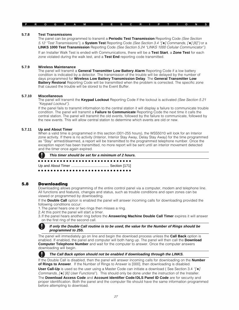
P R O G R A M D E S C R I P T I O N S
27
5.7.8 Test TransmissionsThe panel can be programmed to transmit a Periodic Test Transmission Reporting Code (See Section5.12 “Test Transmissions”), a System Test Reporting Code (See Section 3.4 “[ ] Commands, [ ] [6]”) or aLINKS 1000 Test Transmission Reporting Code (See Section 5.24 “LINKS 1000 Cellular Communicator”).If an Installer Walk Test is ended with Communications, there will be a Test Start , a Zone Test for eachzone violated during the walk test, and a Test End reporting code transmitted.
5.7.9 Wireless MaintenanceThe panel will transmit a General Transmitter Low Battery Alarm Reporting Code if a low batterycondition is indicated by a detector. The transmission of the trouble will be delayed by the number ofdays programmed for Wireless Low Battery Transmission Delay . The General Transmitter LowBattery Restoral Reporting Code will be transmitted when the problem is corrected. The specific zonethat caused the trouble will be stored to the Event Buffer.
5.7.10 MiscellaneousThe panel will transmit the Keypad Lockout Reporting Code if the lockout is activated (See Section 5.21“Keypad Lockout”).If the panel fails to transmit information to the central station it will display a failure to communicate troublecondition. The panel will transmit a Failure to Communicate Reporting Code the next time it calls thecentral station. The panel will transmit the old events, followed by the failure to communicate, followed bythe new events. This will allow central station to determine which events are old or new.
5.7.11 Up and About TimerWhen a valid time is programmed in this section (001-255 hours), the WSS5010 will look for an Interiorzone activity. If there is no activity (Interior, Interior Stay Away, Delay Stay Away) for the time programmedas “Stay” armed/disarmed, a report will be transmitted to the programmed telephone number. Once theexception report has been transmitted, no more report will be sent until an interior movement detectedand the timer once again expired.
This timer should be set for a minimum of 2 hours.
Up and About Timer ...................................... Section [171]
5.8 DownloadingDownloading allows programming of the entire control panel via a computer, modem and telephone line.All functions and features, changes and status, such as trouble conditions and open zones can beviewed or programmed by downloading.If the Double Call option is enabled the panel will answer incoming calls for downloading provided thefollowing conditions occur:1.The panel hears one or two rings then misses a ring.2.At this point the panel will start a timer.3. If the panel hears another ring before the Answering Machine Double Call Timer expires it will answer
on the first ring of the second call.
If only the Double Call routine is to be used, the value for the Number of Rings should beprogrammed to 255.
The panel will immediately go on line and begin the download process unless the Call Back option isenabled. If enabled, the panel and computer will both hang up. The panel will then call the DownloadComputer Telephone Number and wait for the computer to answer. Once the computer answersdownloading will begin.
The Call Back option should not be enabled if downloading through the LINKS.
If the Double Call is disabled, then the panel will answer incoming calls for downloading on the Numberof Rings to Answer . If the Number of Rings to Answer is [000], then downloading is disabled.User Call-Up is used so the user using a Master Code can initiate a download ( See Section 3.4 “[ ]Commands, [ ] [6] User Functions”). This should only be done under the instruction of the Installer.The Download Access Code and Account Identifier Code /DLS Panel ID Code are for security andproper identification. Both the panel and the computer file should have the same information programmedbefore attempting to download.

P R O G R A M D E S C R I P T I O N S
28
PC LinkThe PC Link is used for uploading and downloading with an on-site computer. The PC Link Moduleconnects to the 4 pin header located on the WSS5010 board. The module is placed on the headeraccording to the cut sheet provided with the PC-LINK module.Enter into the DLS package an initiate the direct link mode of operation. Select the operation that isrequired to be performed. On the panel, enter into installer programming and enter into section [490],Initiate PC Link. The system will “Busy” or unavailable for the duration of the Direct Connect session. Formore information, refer to the Download Manual included with the computer software.
After entering a Supervision Enable / Reset (section [902] ), you must wait for five minutesbefore downloading using the PC-LINK.
Double Call ................................................................ Section [401], Option [1]User Call-Up .............................................................. Section [401], Option [2]Call Back .................................................................... Section [401], Option [3]Answering Machine Double Call Timer ..................... Section [405]Download Computer Telephone Number .................. Section [402]Download Access Code ............................................ Section [403]Initiate PC-LINK (Direct Connect Local Download) .. Section [490]Account Identifier Code /DLS Panel ID Code ........... Section [310]
Number of Rings to Answer ...................................... Section [404]
5.9 PGM OutputsThere are 3 different types of Programmable Outputs available. They are listed as follows:• PGM1 and PGM2 on the main board• 8 low current outputs available with the WSS5208 Output Module• 4 high current outputs available with the WSS5204 Power Supply/Output ModuleA PGM Output Option must be selected from the following list:
5.9.1 PGM Output Options
[01] Burglary and Fire Bell OutputThe PGM output will activate when the alarm output is active and will turn off when the alarm output issilenced. If the alarm output is pulsing the PGM output will pulse as well. This output will follow the pre-alert for delayed fire zones, but it only comes on steady for fire zones.
[02] Utility OutputThe PGM output will activate for 5 seconds when the [ ] [7] [1] [Access Code] command is entered (SeeSection 3.4 “[ ] Commands, [ ] [7] Utility Output Functions”).
[03] Sensor ResetThis option is used to reset power for latching smoke detectors.
The output will normally be active, switched to ground.
The output will deactivate for 5 seconds when the [ ] [7] [2] command is entered (See Section 3.4 “[ ]Commands, [ ] [7] Utility Output Functions”) or on the first trip of an auto-verify fire zone. The keypadbuzzer will not sound for the 5 second period.Refer to the Hook-Up diagram in this manual for wiring instructions.
[04] Two-Wire Smoke Support (PGM2 Only!)PGM2 may be used in conjunction with two-wire smoke detectors.The 2 wire smoke can be set up so that it operates as a Delay Fire or an Instant Fire (section [014] light8). Refer to the zone definitions for Delay Fire or Standard Fire zones in order to determine the operationof the 2 wire smoke.
Do not program any PGM output other than PGM2 for two-wire smoke detector support.
Refer to the Hook-Up diagram in this manual for wiring instructions (See Section 2.9.5 “Fire Zone Wiring -2-Wire Smoke Detectors”).
[05] System Armed StatusThe PGM output will activate when the System is armed and deactivate when disarmed.
[06] Ready OutputThe PGM output will activate when the System is ready to arm. The output will deactivate when the systemis not secure or upon arming.

P R O G R A M D E S C R I P T I O N S
29
[07] Keypad Buzzer FollowThe PGM will activate when any of the following events occur and will remain active for as long as thekeypad buzzer is active:• Door Chime • Audible Exit Delay• Entry Delay • 24 Hour Supervisory Buzzer Zone
[08] Courtesy PulseUpon arming the PGM output will activate for the duration of the exit delay plus two minutes. Upon entrythe PGM output will activate for the duration of the entry delay plus two minutes. Only one courtesy pulseoutput may be programmed on a system.
[09] - [11] Not Used
[12] TLM and AlarmThe PGM Output will activate when a telephone line fault condition is present AND an alarm occurs. ThePGM Output will remain active until the panel is disarmed. If the panel is disarmed when the PGM Outputactivates, it will shut off upon arming, TLM restoral or clearing alarm memory. The output will activate forboth audible and silent alarms if a TLM trouble is present.
This output will activate for all audible and silent alarms except Duress, but it will NOTdeactivate using the Duress Code.
[13] KissoffThe PGM Output will activate for two seconds after the panel receives the kissoff from the central station.
[14] Ground Start (Shall not be used on UL Listed systems)The PGM Output will activate for two seconds before the panel attempts to dial to obtain dial tone onGround Start telephone equipment. Two 2-second pauses should be inserted at the beginning of thephone number when using this option.
[15] Remote Operation (DLS Support)The PGM output can be activated or deactivated through the DLS-1 downloading software package.
[16] LINKS 1000 Support (PGM1 Only)The PGM output will be used as a data wire to communicate phone number information for the LINKS1000 cellular unit.
[17] Fire Bell FollowerThe PGM output will activate for any Fire bell activities and will be steady at all times. It will follow the belltime out and activate for Delayed Fire pre-alerts.
[18] Burglary Bell FollowerThe PGM output will activate for any Burglary bell activities. It will follow the bell time out and the bellattribute of the violated zone.
[19] Latched StrobeThe PGM output will activate for any alarm condition and remain on until the following occurs.• In the Armed state, the output will deactivate only when an access code is entered to disarm the system.• If an alarm occurs in the disarmed state, it will deactivate if a code is entered during bell time out or if
the system arms after bell time out. This output will only activate for alarm conditions, but not for pre-alerts or delays.
[20] - [26] These outputs operate similar to option [19], but will operate only for the following conditions.
[20] Latched BurglaryBurglary alarm conditions including Delay, Instant, Interior, Stay Away, 24 Hour Burglary and (Armed)Day zones.
[21] Latched FireFire alarm conditions including Fire key, Standard and Delay zone (1-32) alarms, Auto-Verify Fire zone (1-32) alarms, and 2 wire smoke alarms (PGM).
[22] Latched Panic - Panic alarm conditions including Panic key and Panic zone alarms.
[23] Latched Medical - Medical alarm conditions including Auxiliary key, Medical and Emergency alarms.
[24] Latched SupervisorySupervisory alarm conditions including Supervisory, Freeze Warning and Water Detector zone alarms.
[25] Latched PriorityPriority alarm conditions including Gas, High Temperature, Sprinkler, and 24 Hour Latching Tamper zonealarms.

P R O G R A M D E S C R I P T I O N S
30
[26] Latched Holdup - Holdup alarm conditions including Holdup zone and Duress code alarms.
[27] Auxiliary PGM Type 1 (On/Off)The output is used in conjunction with the WSSFOB button programmed for Auxiliary PGM Type 1 Control. Itwill activate when this button is pressed and will stay ON until the button is pressed again.[28] Auxiliary PGM Type 1 (Pulse)The output is used in conjunction with the WSSFOB button programmed for Auxiliary PGM Type 1 Control. Itwill activate when this button is pressed and will stay ON for the duration of the WSSFOB PGM Pulse Timer.[29] Auxiliary PGM Type 2 (On/Off)This output operates similar to output [27] except when using WSSFOB Auxiliary PGM Type 2 Control option.[30] Auxiliary PGM Type 2 (Pulse)This output operates similar to output [28] except when using WSSFOB Auxiliary PGM Type 2 Control option.
Both the Pulse and On/Off PGMs will be active when a WSSFOB Auxiliary PGM Type 1 or 2Control button – programmed for PGM Output Activation – is pressed.
Main Board PGM Outputs ............................. Section [009]WSS5208 PGM Output Options .................... Section [010]
WSS5204 PGM Output Options .................... Section [011]
5.9.2 WSSFOB PGM Pulse TimerThe WSSFOB PGM pulse timer determines the duration of the Auxiliary PGM Type 1 or 2 (pulse output).This timer can be set from 1 to 255 seconds. The timer will begin upon the receipt of an Auxiliary PGMType 1 or 2 Control signal.
Both the Type 1 and Type 2 pulse outputs will follow this timer. If one of the pulse outputs isON and the other is activated, the timer will be reset and both pulse outputs will follow thetimer from when the second output is activated.
WSSFOB PGM Pulse Timer .......................... Section [172]
5.10 Telephone Line Monitor (TLM)The panel will supervise the presence of the phone line and indicate a trouble condition if disconnected.If TLM Enabled is selected the panel will wait the TLM Trouble Delay time before indicating the troubleso that a momentary interruption of the phone line will not cause a trouble condition.The TLM Trouble Only or Audible When Armed option will allow you to select if the panel will indicate atrouble condition at the keypad or indicate a trouble at the keypad when disarmed and activate the alarmoutput when armed.When the trouble condition is restored the panel can send a TLM Restoral Reporting Code . Any eventsthat occurred while the phone line was down will also be communicated.If the LINKS 1000 cellular communicator is being used the panel can be programmed to report a TLMTrouble Reporting Code .
TLM Enable/Disable ...................................... Section [013], Option [5]TLM Trouble Only or Audible When Armed ... Section [013], Option [6]
TLM Trouble Delay ......................................... Section [370]
5.11 Siren SupervisionThe panel supervises the Bell output. If an open condition is detected or the fuse is blown the panel willimmediately indicate a trouble condition and beep the keypad twice every ten seconds to alert the ownerof the problem. The panel can send a Bell Circuit Trouble Reporting Code immediately. Once theproblem is corrected the panel can send a Bell Circuit Trouble Restoral Reporting Code.
5.12 Test TransmissionTo ensure the communication link with the central station is functioning properly the panel can beprogrammed to send a test transmission signal.The panel can send a Periodic Test Transmission Reporting Code . The Test Transmission Cycledetermines the number of days (001 to 255) between tests. If the test transmission is being programmedwith a lesser value than the previous value, the system will wait the original period before the next testtransmission is sent, and then begin reporting with the new interval.If the LINKS 1000 cellular communicator is being used the panel will also send a cellular test at the sametime as the land line test transmission.The end user can generate a communicator test when the System Test keypad command is entered (SeeSection 3.4 “[ ] Commands, [ ] [6] User Functions”).

P R O G R A M D E S C R I P T I O N S
31
5.13 Fire, Auxiliary, Panic KeysThe emergency keys are available on all keypads. These keys must be pressed and held for 2 secondsbefore they will activate. This 2 second delay is designed to help prevent accidental activation.If the Fire Keys option is enabled, when the Fire keys are pressed and held for 2 seconds, the panel willactivate the alarm output, pulsing one second on, one second off. If Fire Bell Continuous is selected thealarm output will sound until a code is entered, otherwise it will sound until a code is entered or the alarmoutput times out. Communication of the signal to central station is immediate.If the Auxiliary Keys are pressed and held for 2 seconds the panel will sound the keypad beeper three times toverify activation. The panel will beep the keypad ten times rapidly to verify communication to the central station.If the Panic Keys are pressed and held for 2 seconds, the panel will immediately communicate the signalto central station. The panel will beep the keypad three times upon activation and activate the alarmoutput until a code is entered or the alarm output times out.
The Fire, Auxiliary, Panic keys will operate even if Keypad Blanking is active (See Section5.22 “Keypad Blanking”).
Fire Keys Enable ........................................... Section [015], Option [1]
Fire Bell Continuous ...................................... Section [014], Option [5]
5.14 Entry/Exit Delay OptionsUpon arming, the panel will begin the exit delay. If Audible Exit Delay is enabled the keypad will beepevery second until the exit delay expires. The keypad will beep rapidly for the last 10 seconds of exitdelay to warn the user the system is about to arm.Upon entry, if a Delay type zone is violated, the panel will begin entry delay. The keypad will emit asteady tone. The keypad will pulse the keypad sounder during the last 10 seconds to warn the user thesystem is about to go into alarm. If there was an alarm during the armed period, the keypad sounder willpulse for the entire entry delay to warn the user of the previous alarm.
Since two Delay zones are programmable, and therefore two different Entry Delays, when thepanel is armed it will use the Entry Delay for the first Delay zone violated.
If Exit Delay Termination is enabled the panel will monitor the Delay zones during exit delay. If a Delaytype zone is violated then secured during the exit delay, the exit delay will be terminated and the panelwill be armed immediately.To prevent false alarms on exit the WSS5010, use the built-in feature Audible Exit Fault . If a delay typezone is violated 4 seconds after the exit delay has expired, the panel will sound the entry delay warningthrough the keypad and siren alerting the customer that an improper exit was made. If the panel isdisarmed within the entry delay no signal is sent. If not, the panel will continue to sound the alarm andsend a signal to central station.
Audible Exit Delay ......................................... Section [014], Option [3]
Exit Delay Termination ................................... Section [014], Option [4]
5.15 Event BufferThe panel will store the last 128 events that have occurred on the system. Each event will contain thetime, date and the event itself along with the zone number, user code number or any other informationpertaining to the event.If the Event Buffer Follows Swinger Shutdown feature is enabled the event buffer will not store eventsafter the swinger shutdown level has been reached. This will prevent the panel from overwriting the entirebuffer if a problem exists. (See Section 5.16 “Swinger Shutdown”.)The event buffer can be viewed three different ways. It can be viewed through an LCD keypad, printedon-site using the WSS5400 printer module (See Section 5.27 “On-Site Printer”) or it can be uploadedthrough the DLS software.
5.15.1 Viewing the Event Buffer through the LCD KeypadThe following is the procedure for viewing the event buffer through the LCD keypad:Step 1 - Enter [ ] [6] [Master Code]Step 2 - Select ‘View Event Buffer’ by pressing [ ]The keypad will display the Event Number, Time and Date of the event in question. Use the [ ] key to togglebetween this information and the event itself. Use the arrow keys (<>) to scroll through the events in the buffer.When you have finished viewing the event buffer press the [#] key to exit.
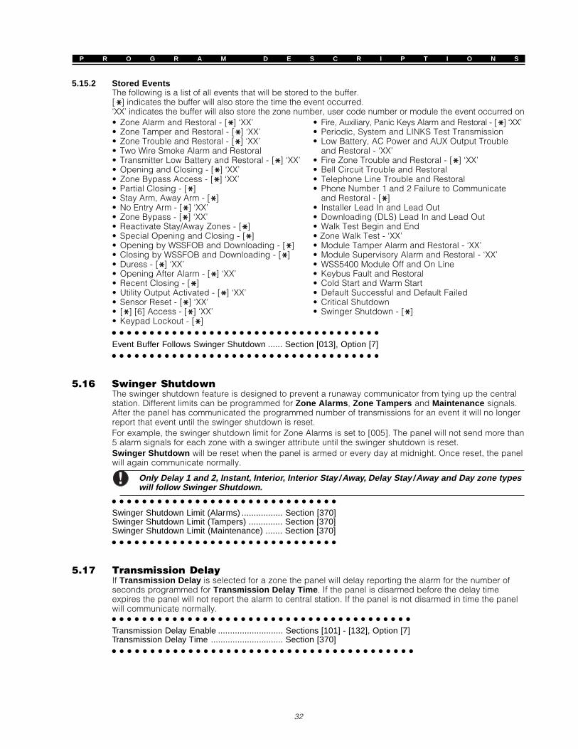
P R O G R A M D E S C R I P T I O N S
32
5.15.2 Stored EventsThe following is a list of all events that will be stored to the buffer.[ ] indicates the buffer will also store the time the event occurred.‘XX’ indicates the buffer will also store the zone number, user code number or module the event occurred on• Zone Alarm and Restoral - [ ] ‘XX’ • Fire, Auxiliary, Panic Keys Alarm and Restoral - [ ] ‘XX’• Zone Tamper and Restoral - [ ] ‘XX’ • Periodic, System and LINKS Test Transmission• Zone Trouble and Restoral - [ ] ‘XX’ • Low Battery, AC Power and AUX Output Trouble• Two Wire Smoke Alarm and Restoral and Restoral - ‘XX’• Transmitter Low Battery and Restoral - [ ] ‘XX’ • Fire Zone Trouble and Restoral - [ ] ‘XX’• Opening and Closing - [ ] ‘XX’ • Bell Circuit Trouble and Restoral• Zone Bypass Access - [ ] ‘XX’ • Telephone Line Trouble and Restoral• Partial Closing - [ ] • Phone Number 1 and 2 Failure to Communicate• Stay Arm, Away Arm - [ ] and Restoral - [ ]• No Entry Arm - [ ] ‘XX’ • Installer Lead In and Lead Out• Zone Bypass - [ ] ‘XX’ • Downloading (DLS) Lead In and Lead Out• Reactivate Stay/Away Zones - [ ] • Walk Test Begin and End• Special Opening and Closing - [ ] • Zone Walk Test - ‘XX’• Opening by WSSFOB and Downloading - [ ] • Module Tamper Alarm and Restoral - ‘XX’• Closing by WSSFOB and Downloading - [ ] • Module Supervisory Alarm and Restoral - ‘XX’• Duress - [ ] ‘XX’ • WSS5400 Module Off and On Line• Opening After Alarm - [ ] ‘XX’ • Keybus Fault and Restoral• Recent Closing - [ ] • Cold Start and Warm Start• Utility Output Activated - [ ] ‘XX’ • Default Successful and Default Failed• Sensor Reset - [ ] ‘XX’ • Critical Shutdown• [ ] [6] Access - [ ] ‘XX’ • Swinger Shutdown - [ ]• Keypad Lockout - [ ]
Event Buffer Follows Swinger Shutdown ...... Section [013], Option [7]
5.16 Swinger ShutdownThe swinger shutdown feature is designed to prevent a runaway communicator from tying up the centralstation. Different limits can be programmed for Zone Alarms , Zone Tampers and Maintenance signals.After the panel has communicated the programmed number of transmissions for an event it will no longerreport that event until the swinger shutdown is reset.For example, the swinger shutdown limit for Zone Alarms is set to [005]. The panel will not send more than5 alarm signals for each zone with a swinger attribute until the swinger shutdown is reset.Swinger Shutdown will be reset when the panel is armed or every day at midnight. Once reset, the panelwill again communicate normally.
Only Delay 1 and 2, Instant, Interior, Interior Stay /Away, Delay Stay /Away and Day zone typeswill follow Swinger Shutdown.
Swinger Shutdown Limit (Alarms) ................. Section [370]Swinger Shutdown Limit (Tampers) .............. Section [370]
Swinger Shutdown Limit (Maintenance) ....... Section [370]
5.17 Transmission DelayIf Transmission Delay is selected for a zone the panel will delay reporting the alarm for the number ofseconds programmed for Transmission Delay Time . If the panel is disarmed before the delay timeexpires the panel will not report the alarm to central station. If the panel is not disarmed in time the panelwill communicate normally.
Transmission Delay Enable ........................... Sections [101] - [132], Option [7]
Transmission Delay Time .............................. Section [370]

P R O G R A M D E S C R I P T I O N S
33
5.18 Keypad BacklightingThe keys of all the keypads can be backlit to provide easy viewing in dim lighting conditions. If theKeypad Backlighting Option is enabled the keys will be illuminated.
Keypad Backlighting Option .......................... Section [015], Option [7]
5.19 Arming /Disarming OptionsIf the Arm/Disarm Bell Squawk option is enabled the panel will squawk the alarm output once uponarming and twice upon disarming.Closing Confirmation , if enabled, will cause the keypad to beep 10 times rapidly after the closingreporting code has been transmitted to central station.
Arm/Disarm Bell Squawk .............................. Section [014], Option [1]
Closing Confirmation ..................................... Section [380], Option [5]
5.20 Bell Output OptionsThe main bell can be enabled and disabled for Burglary zone transitions in section [014] Light 6 and forFire zone transitions in section [014] Light 7.
It is important to have PGMs programmed for a bell type output if either or both of these belloptions are disabled.Bell Squawk features can only be used when the main bell is set for Burglary or Burglary andFire zone transitions.
5.21 Keypad LockoutThe panel can be programmed to ‘lockout’ keypads if a number of incorrect user code entries are made.After the Number of Invalid Codes Before Lockout has been reached the panel will lock out the keypadfor the Lockout Duration and log the event to the event buffer. For the duration of the lockout the panelwill sound an error tone when any key is pressed.
Keypad Lockout will reset every hour.
To disable Keypad Lockout program the Number of Invalid Codes Before Lockout as [000].
Number of Invalid Codes Before Lockout ..... Section [012]
Lockout Duration ........................................... Section [012]
5.22 Keypad BlankingIf the Keypad Blanking Option is enabled the panel will turn off all lights on the keypads except thebacklighting of the keys if no key is pressed for 30 seconds.The panel will turn the lights back on if entry delay begins or an audible alarm occurs. The lights will alsocome on if a key is pressed .The Power Save Mode will blank all keypad lights including backlighting when AC power fails, in order toconserve the back up battery.
Keypad Blanking Option ................................ Section [015], Option [6]
5.23 Loop ResponseThe normal loop response time for all zones is 500 milliseconds. The panel will not consider a zoneviolated unless it is violated for at least 500 milliseconds.
5.24 LINKS 1000 Cellular CommunicatorThe LINKS 1000 cellular communicator can be used as a back up for the first phone number. A LINKSPreamble is programmable for the phone number in the event that the land line number is local but theLINKS is required to dial an exchange. When programming a LINKS Preamble, all unused digits must beprogrammed with a hexa decimal “F”.

P R O G R A M D E S C R I P T I O N S
34
5.24.1 Using the LINKS as a Backup CommunicatorThe panel can be programmed to call using the LINKS 1000 cellular communicator if the panel ishaving difficulty communicating an event using the land line. The LINKS will only backup optionsselected in both the First Telephone Number Dialing Options and the First Telephone Number LINKSBackup Dialing Options.When used as a backup communicator the panel will attempt to call the central station in the following manner:• the panel will try to call using land lines - if unsuccessful the panel will try to call using the LINKS• if unsuccessful the panel will try to call using the land lines• if unsuccessful the panel will try to call using the LINKSThis process will continue until the panel has successfully communicated with the central station or theMaximum Dialing Attempts has been reached.
LINKS Preamble (First Telephone Number) ................................ Section [390]
First Telephone Number LINKS Backup Dialing Options ............ Sections [361]
5.25 Wireless ExpansionAny number of zones, up to 32, can be programmed as wireless. Adding wireless devices to the panel isdone by simply selecting the zone number and entering the 5 digit ESN number written on the unit.If the Zones 1-4 Enable Option is disabled zones 1 to 4 will be disabled for hardwire operation andwireless devices can be substituted. Also if Zones 5-8 Enable Option is disabled zones 5 to 8 will bedisabled for hardwire operation and wireless devices can be substituted.
After disabling or enabling main board zones, the panel should be powered down.Do not add wireless devices to the same zone as a hardwire zone. Hardwire and wirelesszones cannot share the same zone.
Each wireless zone, WSSUTX, WSSPIR, or WSSSMK will send a supervisory round every 12 minutes. If thereceiver hears from the wireless device at least once during the Wireless Supervisory Window it will notreport a trouble. If the receiver does not it will generate a General Zone Supervisory trouble and reportingcode. The panel will report Supervisory trouble by zone using the SIA format (See Section 5.6.1 “SIA”).Within the supervisory transmission the device will also indicate the status of the battery. If a low batterycondition exists the panel will indicate a General Transmitter Low Battery trouble. The panel will delayreporting the event for the number of days programmed for Wireless Low Battery Transmission Delay .If the customer has been instructed on how to replace batteries this will prevent unnecessary reporting ofthe event provided the batteries are changed.A WSS5132-RS tamper will be logged to the event buffer or transmitted as a general system tamper undertwo conditions. It will first occur if the tamper terminals on the WSS5132-RS are open; the tamper will berestored by shorting out these terminals. Second, a tamper will be logged when the WSS5132-RS detectsan attempt to impede RF signals. This advises the monitoring station that the wireless zone transmissionsare not being received by the modules.
5.25.1 Supervision of Wireless ZonesStep 1 - Enter Installer ProgrammingStep 2 - Enter Program Section [804]Step 3 - Enter Sections [82], [83], [84] and [85] to enable or disable supervision by turning the bits on or off
The wireless zone attribute must be set for all enrolled wireless zones. The supervisory bit forany WSSPNCs enrolled on the system must be OFF.
WSS5132-RS Programming .........................................Section [804]
5.26 WSS5580 ModuleMany consumers will often purchase wants before needs. The alarm system is an identifiable needhowever rarely is it an item someone wants. The WSS5580 module will help you change the way in whichthey feel about security.There are many benefits when adding the WSS5580 module to a security system. The WSS5580 module willturn any touch tone phone in the world into a fully functional keypad. Imagine the security a customer wouldfeel if they had the ability to arm, disarm and check status of the alarm while at the office or on vacation.In addition, all touch tone phones in the home also become fully functional keypads. This may help reduce thecost of the overall installation because additional keypads (and labour in running wires) can be eliminated.The WSS5580 will also act as a tutor for the system. By speaking in clear, easy to understand sentences ithelps guide a user through functions they may otherwise have difficulty with. Programmable zone labels(up to 6 words each from our library of over 240 words) makes the system even easier to use.

P R O G R A M D E S C R I P T I O N S
35
The module also has a built-in power line control interface and can control up to 32 power line controldevices for lighting and temperature control, giving you the power to add home automation in a very costeffective manner. Devices can be activated individually, as a group, by schedule or can be activatedwhen an event occurs on the system, such as an alarm.Additional information can be found in the WSS5580 Installation Manual.
Downloading must be enabled in order to use the WSS5580.
5.27 On-Site PrinterThe panel, with the addition of the WSS5400 printer module, will print all events as they occur to a local,on-site serial printer. All events printed will include the time, date and the event.If a problem develops with the printer, such as power loss or paper outage the panel will store events untilthe problem is corrected, at which point it will print the events from the buffer. The panel can store up to128 events if such a condition occurs.
WSS5400 Programming ................................ Sections [801]
5.28 Audio Interface ModuleThe WSS5928 Audio Interface will allow you to connect up to 7 Interior (WSS5923) or exterior(WSS5923EXT) Intercom Stations. These attractive, surface mount stations contain both speaker andmicrophone and will allow you to add intercom features to your alarm system such as:• Page/Answer • Do Not Disturb • Baby Listener Broadcast• Answer Incoming Calls • Doorbell FunctionIn addition to these features the module also has built-in two-way voice for central station monitoring. Thecentral station can select the audio station, listen/talk, extend on-line time and hang up.Each station home-runs to the Audio Interface module using standard 22 gauge, 4 conductor, two pairtwist preferred.For more information regarding the WSS5928 Audio Interface Module refer to the Installation Manual forthe product.
WSS5928 Programming ................................ Sections [802]
5.29 Default (Factory)On occasion it may be necessary to default the main control panel or one of the modules that can beconnected. There are several different defaults available including defaulting the main control panel,WSS5580 module, WSS5132-RS Wireless Expander Module and WSS5400 Printer module.
5.29.1 Factory Default Main Panel (Hardware)To default the main control panel perform the following:Step 1 - Remove AC and battery from the panel.Step 2 - Remove all wires from the Zone 1 and PGM1 terminals.Step 3 - With a piece of wire, short the Zone 1 terminal to the PGM1 terminal.Step 4 - Apply AC power to the main panel.Step 5 - When Zone Light 1 is lit on the keypad the default is complete.Step 6 - Remove AC power from the controlStep 7 - Reconnect all original wiring and power up the control.
AC power must be used to power the panel. The panel will not default if the battery is used.
5.29.2 Factory Default Main Panel (Software) and other ModulesStep 1 - Enter the Installer Programming mode.Step 2 - Enter Program Section [XXX].Step 3 - Enter the Installer Code.Step 4 - Enter Program Section [XXX] again.The panel will take a few seconds to perform the default. When the keypad is again operational the defaultis complete.
For an upgrade from software version 2.0 to 2.1, there will be no automatic programmingdefault.

P R O G R A M D E S C R I P T I O N S
36
Restore Main Panel (Software) to Factory Default Programming ......... Section [999]Restore WSS5580 to Factory Default Programming ............................. Section [995]Restore WSS5132-RS to Factory Default Programming ....................... Section [996]Restore WSS5400 to Factory Default Programming ............................. Section [997]
Restore WSS5928 to Factory Default Programming ............................. Section [998]
5.30 Installer LockoutIf Installer Lockout is selected a hardware default cannot be performed. If a software default isperformed all programming will restore to factory default.When Installer Lockout Disable is selected the panel will restore all programming to factory defaults if ahardware or software default is performed on the main control panel.
To enable Installer Lockout perform the following:Step 1 - Enter Installer ProgrammingStep 2 - Enter Program Section [990]Step 3 - Enter the Installer Code.Step 4 - Enter Program Section [990] again.
To disable Installer Lockout perform the following:Step 1 - Enter Installer Programming.Step 2 - Enter Program Section [991].Step 3 - Enter the Installer Code.Step 4 - Enter Program Section [991] again.
5.31 Walk Test (Installer)The Installer Walk Test can be entered in 2 different modes.
During Walk Test, [F], [A] and [P] keys, and 2-wire smokes will report real alarms. In order totest these, call the monitoring station to notify once walk test has started.Violating a fire zone in walk test will transmit a zone tamper.One walk test must be ended before another walk test can be started.
5.31.1 Buzzer Walk Test ModeEnter the following to perform this walk test:Step 1 - Enter Installer ProgrammingStep 2 - Enter Section [980]When any zone is violated the panel will activate the keypad buzzer for 2 seconds and log to theEvent Buffer.
Latched PGM outputs will activate for zone types 1 to 9, 87 and 88.
5.31.2 Bell /Buzzer Walk Test ModeEnter the following to perform this walk test:Step 1 - Enter Installer ProgrammingStep 2 - Enter Section [981]When any zone is violated the panel will activate the Bell output and the keypad buzzer for 2 seconds andlog to the Event Buffer.The Installer Walk Test can be ended in 2 different modes.
All zones opened during the test must be restored upon completion of the Walk Test.
5.31.3 To end the Installer Walk Test with no communicationsEnter the following to end this walk test with no communications:Step 1 - Enter Installer ProgrammingStep 2 - Enter Section [982]This will cause the panel to exit Installer’s Programming.
5.31.4 To end the Installer Walk Test with communicationsEnter the following to end this walk test with communications:Step 1 - Enter Installer ProgrammingStep 2 - Enter Section [983]This will cause the panel to exit Installer’s Programming, and communicate to the monitoring station thezones that were violated during the walk test.
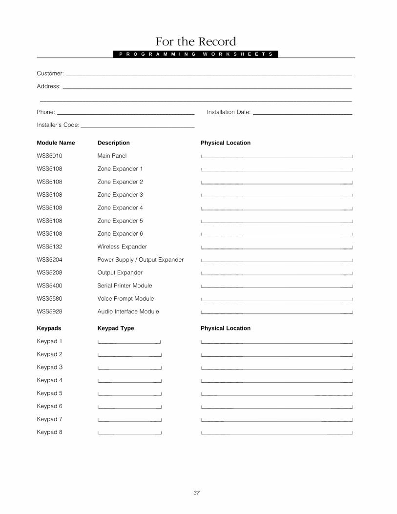
P R O G R A M M I N G W O R K S H E E T S
37
Customer: ________________________________________________________________________________________
Address: _________________________________________________________________________________________
________________________________________________________________________________________________
Phone: _______________________________________________ Installation Date: __________________________________
Installer’s Code: _______________________________________
Module Name Description Physical Location
WSS5010 Main Panel I________________________________________________________________________________________________I
WSS5108 Zone Expander 1 I________________________________________________________________________________________________I
WSS5108 Zone Expander 2 I________________________________________________________________________________________________I
WSS5108 Zone Expander 3 I________________________________________________________________________________________________I
WSS5108 Zone Expander 4 I________________________________________________________________________________________________I
WSS5108 Zone Expander 5 I________________________________________________________________________________________________I
WSS5108 Zone Expander 6 I________________________________________________________________________________________________I
WSS5132 Wireless Expander I________________________________________________________________________________________________I
WSS5204 Power Supply / Output Expander I________________________________________________________________________________________________I
WSS5208 Output Expander I________________________________________________________________________________________________I
WSS5400 Serial Printer Module I________________________________________________________________________________________________I
WSS5580 Voice Prompt Module I________________________________________________________________________________________________I
WSS5928 Audio Interface Module I________________________________________________________________________________________________I
Keypads Keypad Type Physical Location
Keypad 1 I_______________________________________I I________________________________________________________________________________________________I
Keypad 2 I________________________________________________I I________________________________________________________________________________________________I
Keypad 3 I________________________________________I I________________________________________________________________________________________________I
Keypad 4 I________________________________________I I________________________________________________________________________________________________I
Keypad 5 I________________________________________I I________________________________________________________________________________________________I
Keypad 6 I________________________________________I I________________________________________________________________________________________________I
Keypad 7 I________________________________________I I________________________________________________________________________________________________I
Keypad 8 I________________________________________I I________________________________________________________________________________________________I
For the Record
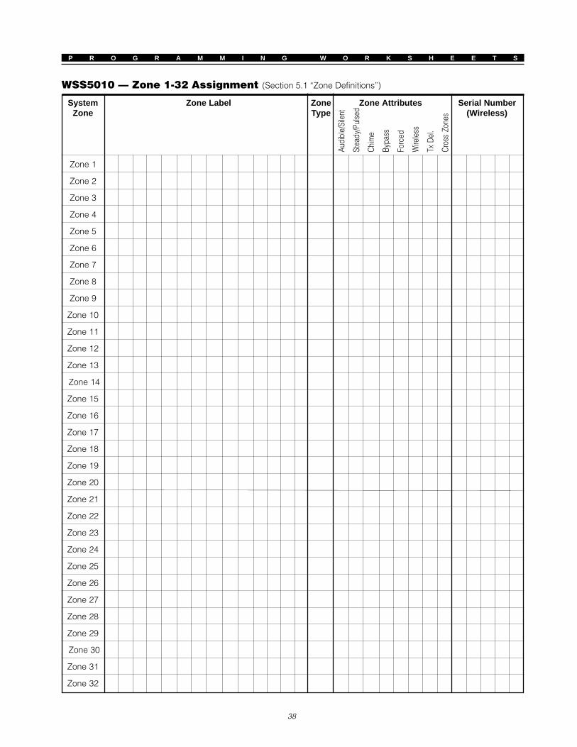
P R O G R A M M I N G W O R K S H E E T S
38
System Zone Label Zone Zone Attributes Serial NumberZone Type (Wireless)
Zone 1
Zone 2
Zone 3
Zone 4
Zone 5
Zone 6
Zone 7
Zone 8
Zone 9
Zone 10
Zone 11
Zone 12
Zone 13
Zone 14
Zone 15
Zone 16
Zone 17
Zone 18
Zone 19
Zone 20
Zone 21
Zone 22
Zone 23
Zone 24
Zone 25
Zone 26
Zone 27
Zone 28
Zone 29
Zone 30
Zone 31
Zone 32
Audi
ble/
Sile
nt
Stea
dy/P
ulse
d
Chim
e
Bypa
ss
Forc
ed
Wire
less
Tx D
el.
Cros
s Zo
nes
WSS5010 — Zone 1-32 Assignment (Section 5.1 “Zone Definitions”)
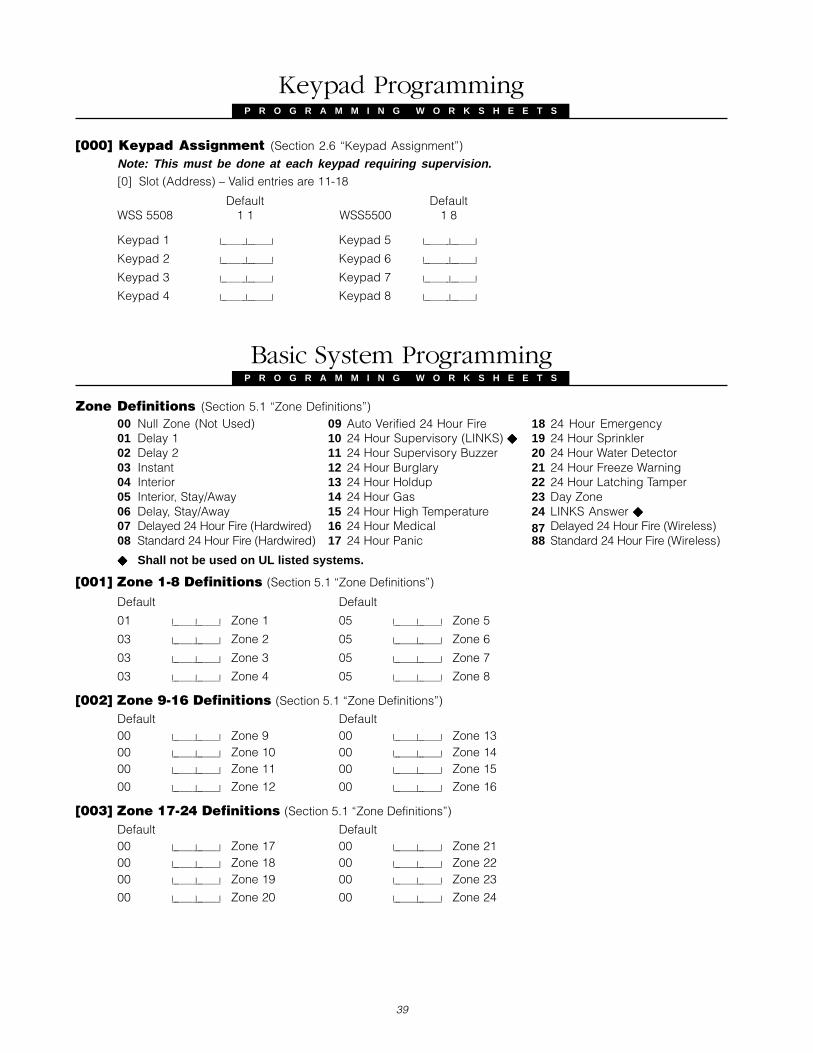
P R O G R A M M I N G W O R K S H E E T S
39
[000] Keypad Assignment (Section 2.6 “Keypad Assignment”)
Note: This must be done at each keypad requiring supervision.[0] Slot (Address) – Valid entries are 11-18
Default DefaultWSS 5508 1 1 WSS5500 1 8
Keypad 1 I________I________I Keypad 5 I________I________I
Keypad 2 I________I________I Keypad 6 I________I________I
Keypad 3 I________I________I Keypad 7 I________I________I
Keypad 4 I________I________I Keypad 8 I________I________I
Basic System ProgrammingP R O G R A M M I N G W O R K S H E E T S
Zone Definitions (Section 5.1 “Zone Definitions”)00 Null Zone (Not Used) 09 Auto Verified 24 Hour Fire 18 24 Hour Emergency01 Delay 1 10 24 Hour Supervisory (LINKS) 19 24 Hour Sprinkler02 Delay 2 11 24 Hour Supervisory Buzzer 20 24 Hour Water Detector03 Instant 12 24 Hour Burglary 21 24 Hour Freeze Warning04 Interior 13 24 Hour Holdup 22 24 Hour Latching Tamper05 Interior, Stay/Away 14 24 Hour Gas 23 Day Zone06 Delay, Stay/Away 15 24 Hour High Temperature 24 LINKS Answer
07 Delayed 24 Hour Fire (Hardwired) 16 24 Hour Medical 87 Delayed 24 Hour Fire (Wireless)08 Standard 24 Hour Fire (Hardwired) 17 24 Hour Panic 88 Standard 24 Hour Fire (Wireless)
Shall not be used on UL listed systems.
[001] Zone 1-8 Definitions (Section 5.1 “Zone Definitions”)
Default Default
01 I_______I_______I Zone 1 05 I_______I_______I Zone 5
03 I_______I_______I Zone 2 05 I_______I_______I Zone 6
03 I_______I_______I Zone 3 05 I_______I_______I Zone 7
03 I_______I_______I Zone 4 05 I_______I_______I Zone 8
[002] Zone 9-16 Definitions (Section 5.1 “Zone Definitions”)
Default Default00 I_______I_______I Zone 9 00 I_______I_______I Zone 1300 I_______I_______I Zone 10 00 I_______I_______I Zone 1400 I_______I_______I Zone 11 00 I_______I_______I Zone 15
00 I_______I_______I Zone 12 00 I_______I_______I Zone 16
[003] Zone 17-24 Definitions (Section 5.1 “Zone Definitions”)
Default Default00 I_______I_______I Zone 17 00 I_______I_______I Zone 2100 I_______I_______I Zone 18 00 I_______I_______I Zone 2200 I_______I_______I Zone 19 00 I_______I_______I Zone 23
00 I_______I_______I Zone 20 00 I_______I_______I Zone 24
P R O G R A M M I N G W O R K S H E E T S
Keypad Programming

P R O G R A M M I N G W O R K S H E E T S
40
[004] Zone 25-32 Definitions (Section 5.1 “Zone Definitions”)
Default Default00 I_______I_______I Zone 25 00 I_______I_______I Zone 2900 I_______I_______I Zone 26 00 I_______I_______I Zone 3000 I_______I_______I Zone 27 00 I_______I_______I Zone 31
00 I_______I_______I Zone 28 00 I_______I_______I Zone 32
[005] System TimesDefault030 I_______I_______I_______I Entry Delay 1 Enter 3 digits from [000-255]120 I_______I_______I_______I Entry Delay 2 Enter 3 digits from [000-255]060 I_______I_______I_______I Exit Delay Enter 3 digits from [000-255]
006 I_______I_______I_______I Bell Cut-off Enter 3 digits from [000-255]
[006] Installer’s Code (Section 4.1 “How to Enter Installer Programming”)
I_______I_______I_______I_______I_______I_______I Enter 6 decimal digits
[007] Master Code (Section 3.1 “Access Codes”)
Default: 1234 I_______I_______I_______I_______I Enter 4 decimal digits
Programmable Output Options (Section 5.9 “PGM Outputs”)
00 Not used 15 Remote Operation (DLS-1 Support)01 Burglary and Fire Bell Output 16 LINKS 1000 Support (PGM 1 only)02 Utility Output 17 Fire Bell03 Sensor Reset 18 Burglary Bell04 2-Wire Smoke Support (PGM2 ONLY) 19 Latched Strobe05 System Armed Status 20 Latched Burglary06 Ready To Arm 21 Latched Fire07 Keypad Buzzer Follow Mode 22 Latched Panic08 Courtesy Pulse 23 Latched Medical09 For future use 24 Latched Supervisory10 For future use 25 Latched Priority11 For future use 26 Latched Holdup12 TLM and Alarm 27 Auxiliary PGM Type 1 (ON/OFF)13 Kissoff Output 28 Auxiliary PGM Type 1 (Pulse)14 Ground Start Pulse 29 Auxiliary PGM Type 2 (ON/OFF)
30 Auxiliary PGM Type 2 (Pulse)
[009] WSS5010 PGM Output Programming (PGM 1 & 2) (Section 5.9 “PGM Outputs”)
Default
02 I_______I_______I PGM 1 03 I_______I_______I PGM 2
[010] WSS5208 PGM Output Programming (PGM 3-10) (Section 5.9 “PGM Outputs”)
Default Default
01 I_______I_______I PGM 3 01 I_______I_______I PGM 7
01 I_______I_______I PGM 4 01 I_______I_______I PGM 8
01 I_______I_______I PGM 5 01 I_______I_______I PGM 9
01 I_______I_______I PGM 6 01 I_______I_______I PGM 10
[011] WSS5204 PGM Output Programming (PGM 11-14) (Section 5.9 “PGM Outputs”)
Default
01 I_______I_______I PGM 11 01 I_______I_______I PGM 13
01 I_______I_______I PGM 12 01 I_______I_______I PGM 14

41
P R O G R A M M I N G W O R K S H E E T S
[012] Keypad Lockout Options (Section 5.21 “Keypad Lockout”)
Default
005 I_______I_______I_______I Number of Invalid Codes Before Lockout
001 I_______I_______I_______I Lockout Duration (in minutes)
[013] First System Option CodeDefault Option ON OFF Section
OFF I________I 11111 Normally Closed Loops End-of-Line Resistors 2.9
OFF I________I 22222 Double End-of-Line Resistors Single End-of-Line Resistors 2.9
ON I________I 33333 On-board Zones 1-4 enabled On-board Zones 1-4 disabled 5.25
ON I________I 44444 On-board Zones 5-8 enabled On-board Zones 5-8 disabled 5.25
OFF I________I 55555 TLM Enabled TLM Disabled 5.10
ON I________I 66666 TLM Audible When Armed TLM Trouble Only When Armed 5.10
ON I________I 77777 Event Buffer Follows Swinger Shutdown Event Buffer Logs Events Past shutdown 5.15
OFF I________I 88888 For Future Use Required for UL listed Systems.
[014] Second System Option CodeDefault Option ON OFF Section
OFF I________I 11111 Arm / Disarm Bell Squawk enabled Arm / Disarm Bell Squawk disabled 5.19
OFF I________I 22222 Bell Squawk on Trouble No Bell Squawk on Trouble 3.4
ON I________I 33333 Audible Exit Beeps with Urgency Silent Exit Delay 5.14
OFF I________I 44444 Exit Delay Termination Enabled Exit Delay Termination disabled 5.14
OFF I________I 55555 Fire Bell does not follow Bell Cut-off Fire Bell follows Bell Cut-off 5.1
ON I________I 66666 Bell Output Burglary enabled Bell Output Burglary disabled 5.20
ON I________I 77777 Bell Output Fire enabled Bell Output Fire disabled 5.20
ON I________I 88888 Delayed Two-Wire Smoke on PGM2 Instant Two-Wire Smoke on PGM2 5.9 Required for UL Grade A Systems.
[015] Third System Option CodeDefault Option ON OFF Section
ON I________I 11111 [F] Keys Enabled [F] Keys Disabled 5.13
ON I________I 22222 Quick Exit Enabled Quick Exit Disabled 3.5
ON I________I 33333 Arming Keys Do Not Require Access Code Arming Keys Require Access Code 3.2
OFF I________I 44444 Master Code Not Changeable Master Code Changeable 3.1
OFF I________I 55555 For Future Use
OFF I________I 66666 Blank Keypad when Not Used Keypad Active 5.22
ON I________I 77777 Keypad Backlighting enabled Keypad Backlighting disabled 5.18
ON I________I 88888 Bypass Status Displayed While Armed Bypass Status Not Displayed While Armed 3.4
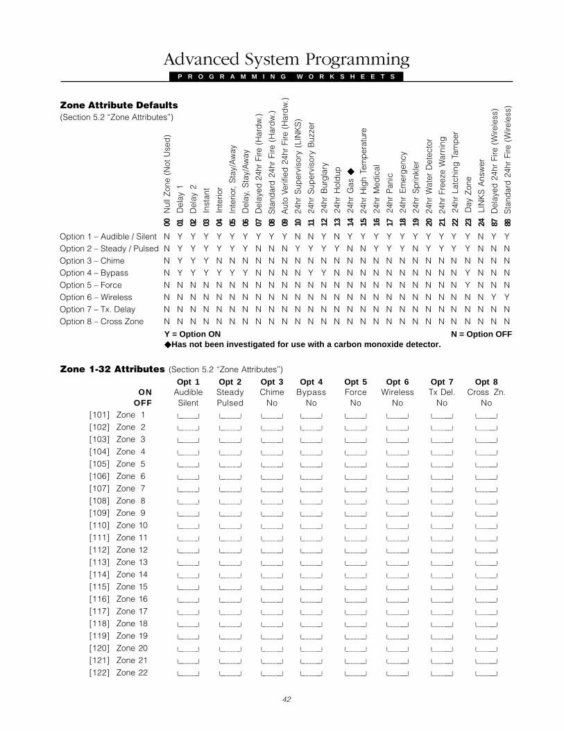
42
P R O G R A M M I N G W O R K S H E E T S
Advanced System Programming
Option 1 – Audible / Silent N Y Y Y Y Y Y Y Y Y N N Y N Y Y Y Y Y Y Y Y Y Y N Y YOption 2 – Steady / Pulsed N Y Y Y Y Y Y N N N Y Y Y Y N N Y Y Y N Y Y Y Y N N NOption 3 – Chime N Y Y Y N N N N N N N N N N N N N N N N N N N N N N NOption 4 – Bypass N Y Y Y Y Y Y N N N N Y Y N N N N N N N N N N Y N N NOption 5 – Force N N N N N N N N N N N N N N N N N N N N N N N Y N N NOption 6 – Wireless N N N N N N N N N N N N N N N N N N N N N N N N N Y YOption 7 – Tx. Delay N N N N N N N N N N N N N N N N N N N N N N N N N N NOption 8 – Cross Zone N N N N N N N N N N N N N N N N N N N N N N N N N N N
Y = Option ON N = Option OFF Has not been investigated for use with a carbon monoxide detector.
00
Nul
l Zon
e (N
ot U
sed
)
01
Del
ay 1
02
Del
ay 2
03
Inst
ant
04
Inte
rior
05
Inte
rior,
Sta
y/A
way
06
Del
ay,
Sta
y/A
way
07
Del
ayed
24h
r Fi
re (
Har
dw
.)
08 S
tand
ard
24h
r Fi
re (
Har
dw
.)
09 A
uto
Verif
ied
24h
r Fi
re (
Har
dw
.)
10
24hr
Sup
ervi
sory
(LI
NK
S)
11
24hr
Sup
ervi
sory
Buz
zer
12
24hr
Bur
gla
ry
13
24hr
Hol
dup
14
24hr
Gas
15
24hr
Hig
h Te
mp
erat
ure
16
24hr
Med
ical
17
24hr
Pan
ic
18
24hr
Em
erg
ency
19
24hr
Sp
rinkl
er
20
24hr
Wat
er D
etec
tor 2222 2
21 2
4hr
Free
ze W
arni
ng 3333 3
22
24hr
Lat
chin
g T
amp
er
23
Day
Zon
e
24
LIN
KS
Ans
wer
87
Del
ayed
24h
r Fi
re (
Wire
less
)
88 S
tand
ard
24h
r Fi
re (
Wire
less
)Zone Attribute Defaults(Section 5.2 “Zone Attributes”)
Zone 1-32 Attributes (Section 5.2 “Zone Attributes”)
Opt 1 Opt 2 Opt 3 Opt 4 Opt 5 Opt 6 Opt 7 Opt 8ON Audible Steady Chime Bypass Force Wireless Tx Del. Cross Zn.
OFF Silent Pulsed No No No No No No[101] Zone 1 I________I I________| I________| I________| I________| I________| I________| I________I
[102] Zone 2 I________I I________| I________| I________| I________| I________| I________| I________I
[103] Zone 3 I________I I________| I________| I________| I________| I________| I________| I________I
[104] Zone 4 I________I I________| I________| I________| I________| I________| I________| I________I
[105] Zone 5 I________I I________| I________| I________| I________| I________| I________| I________I
[106] Zone 6 I________I I________| I________| I________| I________| I________| I________| I________I
[107] Zone 7 I________I I________| I________| I________| I________| I________| I________| I________I
[108] Zone 8 I________I I________| I________| I________| I________| I________| I________| I________I
[109] Zone 9 I________I I________| I________| I________| I________| I________| I________| I________I
[110] Zone 10 I________I I________| I________| I________| I________| I________| I________| I________I
[111] Zone 11 I________I I________| I________| I________| I________| I________| I________| I________I
[112] Zone 12 I________I I________| I________| I________| I________| I________| I________| I________I
[113] Zone 13 I________I I________| I________| I________| I________| I________| I________| I________I
[114] Zone 14 I________I I________| I________| I________| I________| I________| I________| I________I
[115] Zone 15 I________I I________| I________| I________| I________| I________| I________| I________I
[116] Zone 16 I________I I________| I________| I________| I________| I________| I________| I________I
[117] Zone 17 I________I I________| I________| I________| I________| I________| I________| I________I
[118] Zone 18 I________I I________| I________| I________| I________| I________| I________| I________I
[119] Zone 19 I________I I________| I________| I________| I________| I________| I________| I________I
[120] Zone 20 I________I I________| I________| I________| I________| I________| I________| I________I
[121] Zone 21 I________I I________| I________| I________| I________| I________| I________| I________I
[122] Zone 22 I________I I________| I________| I________| I________| I________| I________| I________I
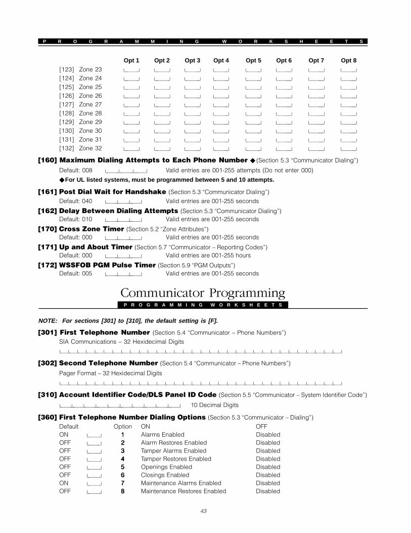
43
P R O G R A M M I N G W O R K S H E E T S
[123] Zone 23 I________I I________| I________| I________| I________| I________| I________| I________I
[124] Zone 24 I________I I________| I________| I________| I________| I________| I________| I________I
[125] Zone 25 I________I I________| I________| I________| I________| I________| I________| I________I
[126] Zone 26 I________I I________| I________| I________| I________| I________| I________| I________I
[127] Zone 27 I________I I________| I________| I________| I________| I________| I________| I________I
[128] Zone 28 I________I I________| I________| I________| I________| I________| I________| I________I
[129] Zone 29 I________I I________| I________| I________| I________| I________| I________| I________I
[130] Zone 30 I________I I________| I________| I________| I________| I________| I________| I________I
[131] Zone 31 I________I I________| I________| I________| I________| I________| I________| I________I
[132] Zone 32 I________I I________| I________| I________| I________| I________| I________| I________I
[160] Maximum Dialing Attempts to Each Phone Number (Section 5.3 “Communicator Dialing”)
Default: 008 I_______I_______I_______I Valid entries are 001-255 attempts (Do not enter 000)
For UL listed systems, must be programmed between 5 and 10 attempts.
[161] Post Dial Wait for Handshake (Section 5.3 “Communicator Dialing”)
Default: 040 I_______I_______I_______I Valid entries are 001-255 seconds
[162] Delay Between Dialing Attempts (Section 5.3 “Communicator Dialing”)Default: 010 I_______I_______I_______I Valid entries are 001-255 seconds
[170] Cross Zone Timer (Section 5.2 “Zone Attributes”)Default: 000 I_______I_______I_______I Valid entries are 001-255 seconds
[171] Up and About Timer (Section 5.7 “Communicator – Reporting Codes”)Default: 000 I_______I_______I_______I Valid entries are 001-255 hours
[172] WSSFOB PGM Pulse Timer (Section 5.9 “PGM Outputs”)Default: 005 I_______I_______I_______I Valid entries are 001-255 seconds
Communicator ProgrammingP R O G R A M M I N G W O R K S H E E T S
NOTE: For sections [301] to [310], the default setting is [F].
[301] First Telephone Number (Section 5.4 “Communicator – Phone Numbers”)
SIA Communications – 32 Hexidecimal Digits
I_____I_____I_____I_____I_____I_____I_____I_____I_____I_____I_____I_____I_____I_____I_____I_____I_____I_____I_____I_____I_____I_____I_____I_____I_____I_____I_____I_____I_____I_____I_____I_____I
[302] Second Telephone Number (Section 5.4 “Communicator – Phone Numbers”)
Pager Format – 32 Hexidecimal Digits
I_____I_____I_____I_____I_____I_____I_____I_____I_____I_____I_____I_____I_____I_____I_____I_____I_____I_____I_____I_____I_____I_____I_____I_____I_____I_____I_____I_____I_____I_____I_____I_____I
[310] Account Identifier Code/DLS Panel ID Code (Section 5.5 “Communicator – System Identifier Code”)
I_______I_______I_______I_______I_______I_______I_______I_______I_______I_______I 10 Decimal Digits
[360] First Telephone Number Dialing Options (Section 5.3 “Communicator – Dialing”)
Default Option ON OFFON I________I 11111 Alarms Enabled DisabledOFF I________I 22222 Alarm Restores Enabled DisabledOFF I________I 33333 Tamper Alarms Enabled DisabledOFF I________I 44444 Tamper Restores Enabled DisabledOFF I________I 55555 Openings Enabled DisabledOFF I________I 66666 Closings Enabled DisabledON I________I 77777 Maintenance Alarms Enabled DisabledOFF I________I 88888 Maintenance Restores Enabled Disabled
Opt 1 Opt 2 Opt 3 Opt 4 Opt 5 Opt 6 Opt 7 Opt 8
P R O G R A M M I N G W O R K S H E E T S

P R O G R A M M I N G W O R K S H E E T S
44
[361] First Telephone Number LINKS Backup Dialing Options (Section 5.3 “Communicator –Dialing”)
Default Option ON OFFOFF I________I 11111 Alarms Enabled DisabledOFF I________I 22222 Alarm Restores Enabled DisabledOFF I________I 33333 Tamper Alarms Enabled DisabledOFF I________I 44444 Tamper Restores Enabled DisabledOFF I________I 55555 Openings Enabled DisabledOFF I________I 66666 Closings Enabled DisabledOFF I________I 77777 Maintenance Alarms Enabled DisabledOFF I________I 88888 Maintenance Restores Enabled Disabled
[365] Second Telephone Number Dialing Options (Section 5.3 “Communicator – Dialing”)
Default Option ON OFFOFF I________I 11111 Closings Enabled DisabledOFF I________I 22222 Openings Enabled DisabledOFF I________I 33333 General System Event Enabled Disabled
OFF I________I 4-84-84-84-84-8 For Future Use
[370] Communication VariablesDefault Section005 I_______I_______I_______I Swinger Shutdown (Alarms and Rest) (001-014 Transmissions, 000=disabled) 5.16005 I_______I_______I_______I Swinger Shutdown (Tampers and Rest) (001-014 Transmissions, 000=disabled) 5.16005 I_______I_______I_______I Swinger Shutdown (Maint and Rest) (001-014 Transmissions, 000=disabled) 5.16000 I_______I_______I_______I Communication Delay (001-255 seconds) 5.17060 I_______I_______I_______I AC Failure Communication Delay (001-255 minutes) 3.4006 I_______I_______I_______I TLM Trouble Delay (No. of valid checks required - 000-255 x 10s) 5.10000 I_______I_______I_______I Test Transmission Cycle (001-255 days; 000 to disable) 5.12007 I_______I_______I_______I Transmitter Low Battery Transmission Delay (000-255 days) 5.25 Shall not be used on UL listed systems.
Must be set to 001 for UL listed systems.
[380] First Communicator Option CodeDefault Option ON OFF SectionON I_______I 11111 Communications Enabled Communications Disabled 5.3ON I_______I 22222 Restorals on Bell Time-out Restorals Follow Zones 5.7OFF I_______I 33333 Pulse Dialing DTMF Dialing 5.3ON I_______I 44444 Switch to Pulse Dialing on 5th Attempt DTMF Dial For All Attempts 5.3OFF I_______I 55555 Closing Confirmation Enabled Disabled 5.14OFF I_______I 66666 Partial Closings are Identified Partial Closings are not Identified 5.7OFF I_______I 7-87-87-87-87-8 For Future Use
Required for commercial burglary applications.
[390] LINKS Preamble (Telephone Number) (Section 5.24 “LINKS 1000 Cellular Communicator”)
Default
FFFF I_______I_______I_______I_______I (Program all unused digits with Hex F)
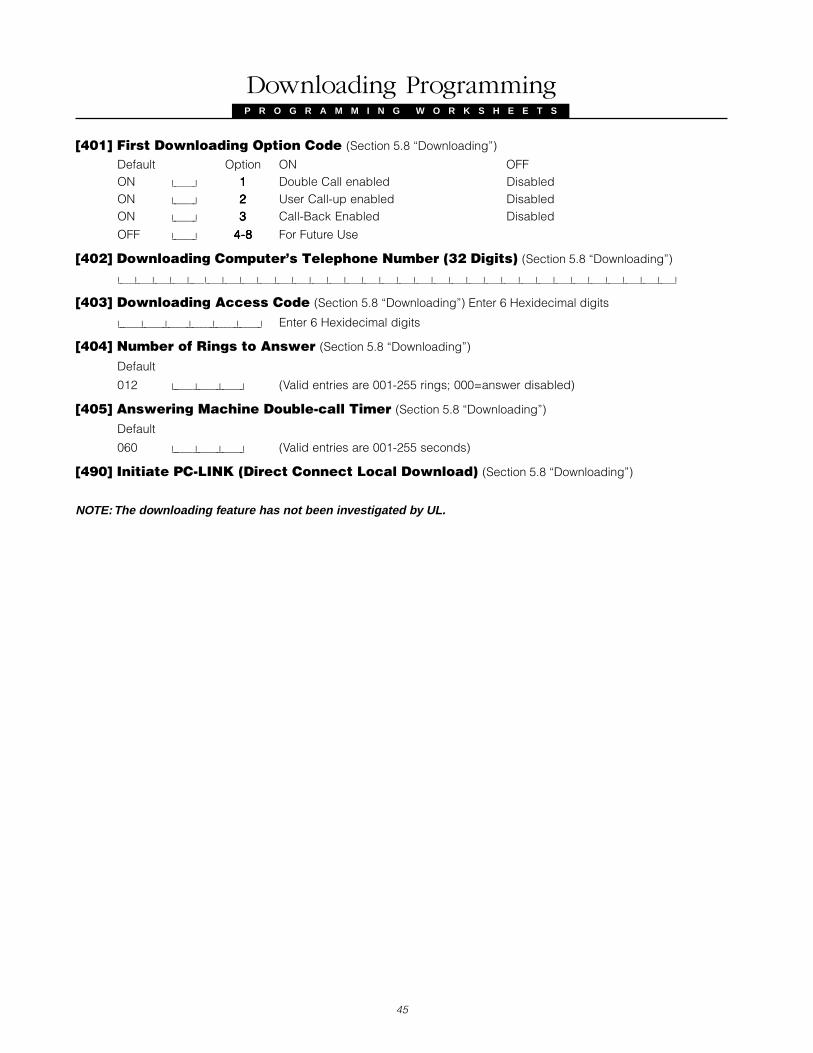
P R O G R A M M I N G W O R K S H E E T S
45
[401] First Downloading Option Code (Section 5.8 “Downloading”)
Default Option ON OFFON I_______I 11111 Double Call enabled DisabledON I_______I 22222 User Call-up enabled DisabledON I_______I 33333 Call-Back Enabled Disabled
OFF I_______I 4-84-84-84-84-8 For Future Use
[402] Downloading Computer’s Telephone Number (32 Digits) (Section 5.8 “Downloading”)
I_____I_____I_____I_____I_____I_____I_____I_____I_____I_____I_____I_____I_____I_____I_____I_____I_____I_____I_____I_____I_____I_____I_____I_____I_____I_____I_____I_____I_____I_____I_____I_____I
[403] Downloading Access Code (Section 5.8 “Downloading”) Enter 6 Hexidecimal digits
I_______I_______I_______I_______I_______I_______I Enter 6 Hexidecimal digits
[404] Number of Rings to Answer (Section 5.8 “Downloading”)
Default
012 I_______I_______I_______I (Valid entries are 001-255 rings; 000=answer disabled)
[405] Answering Machine Double-call Timer (Section 5.8 “Downloading”)
Default
060 I_______I_______I_______I (Valid entries are 001-255 seconds)
[490] Initiate PC-LINK (Direct Connect Local Download) (Section 5.8 “Downloading”)
NOTE: The downloading feature has not been investigated by UL.
Downloading Programming

46
P R O G R A M M I N G W O R K S H E E T S
Module Programming
[801] RS232 Module (WSS5400) Programming (Section 5.27 “On-Site Printer”)[01] Printer ConfigurationDefault Option ON OFF
OFF I_______I 11111 Printer Enabled Printer Disabled
ON I_______I 22222 Handshake from Printer (DTR) No Handshake
OFF I_______I 33333 80 Column Printer 40 Column Printer
OFF I_______I 44444 300 Baud enabled 300 Baud disabled
OFF I_______I 55555 1200 Baud enabled 1200 Baud disabled
ON I_______I 66666 2400 Baud enabled 2400 Baud disabled
OFF I_______I 77777 4800 Baud enabled 4800 Baud disabled
OFF I_______I 88888 For Future Use
[05] Language SelectionDefault
01 I_______I_______I Printer Language (01 = English, 02 = French, 03 = Spanish)
Shall not be used on UL listed systems.
[804] WSS5132 Wireless Expansion Programming (Section 5.25 “Wireless Expansion”)• 5 digit decimal entry is required• First digit represents transmitter type (0, 1, 8-9 are not valid)
2=UTX/SLX, 3=PIR, 4=SMOKE, 5=Pendant, 6=Fob, 7=Handheld Keypad• Next 4 digits represent the serial number (valid entries are 0001 to 4094)
Zone Serial NumbersDefault = 00000[01][01][01][01][01] Zone 1 I_______I_______I_______I_______I_______I [17][17][17][17][17] Zone 17 I_______I_______I_______I_______I_______I
[02][02][02][02][02] Zone 2 I_______I_______I_______I_______I_______I [18][18][18][18][18] Zone 18 I_______I_______I_______I_______I_______I
[03][03][03][03][03] Zone 3 I_______I_______I_______I_______I_______I [19][19][19][19][19] Zone 19 I_______I_______I_______I_______I_______I
[04][04][04][04][04] Zone 4 I_______I_______I_______I_______I_______I [20][20][20][20][20] Zone 20 I_______I_______I_______I_______I_______I
[05][05][05][05][05] Zone 5 I_______I_______I_______I_______I_______I [21][21][21][21][21] Zone 21 I_______I_______I_______I_______I_______I
[06][06][06][06][06] Zone 6 I_______I_______I_______I_______I_______I [22][22][22][22][22] Zone 22 I_______I_______I_______I_______I_______I
[07][07][07][07][07] Zone 7 I_______I_______I_______I_______I_______I [23][23][23][23][23] Zone 23 I_______I_______I_______I_______I_______I
[08][08][08][08][08] Zone 8 I_______I_______I_______I_______I_______I [24][24][24][24][24] Zone 24 I_______I_______I_______I_______I_______I
[09][09][09][09][09] Zone 9 I_______I_______I_______I_______I_______I [25][25][25][25][25] Zone 25 I_______I_______I_______I_______I_______I
[10][10][10][10][10] Zone 10 I_______I_______I_______I_______I_______I [26][26][26][26][26] Zone 26 I_______I_______I_______I_______I_______I
[11][11][11][11][11] Zone 11 I_______I_______I_______I_______I_______I [27][27][27][27][27] Zone 27 I_______I_______I_______I_______I_______I
[12][12][12][12][12] Zone 12 I_______I_______I_______I_______I_______I [28][28][28][28][28] Zone 28 I_______I_______I_______I_______I_______I
[13][13][13][13][13] Zone 13 I_______I_______I_______I_______I_______I [29][29][29][29][29] Zone 29 I_______I_______I_______I_______I_______I
[14][14][14][14][14] Zone 14 I_______I_______I_______I_______I_______I [30][30][30][30][30] Zone 30 I_______I_______I_______I_______I_______I
[15][15][15][15][15] Zone 15 I_______I_______I_______I_______I_______I [31][31][31][31][31] Zone 31 I_______I_______I_______I_______I_______I
[16][16][16][16][16] Zone 16 I_______I_______I_______I_______I_______I [32][32][32][32][32] Zone 32 I_______I_______I_______I_______I_______I
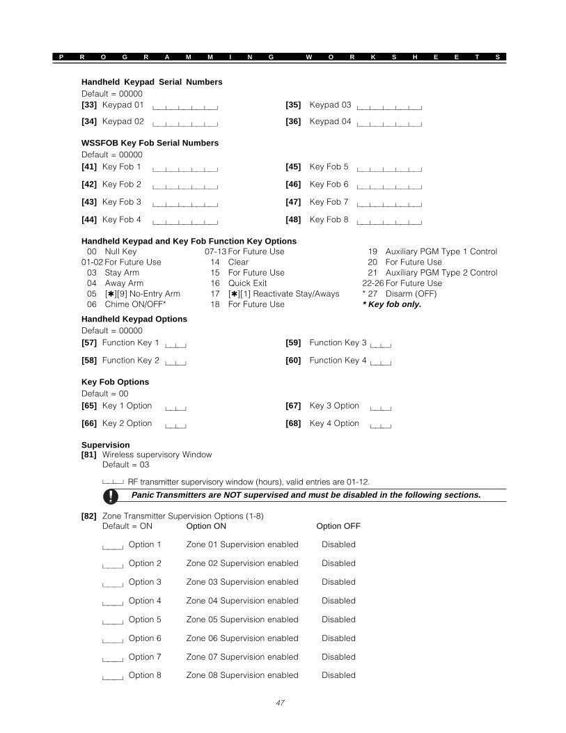
47
P R O G R A M M I N G W O R K S H E E T S
Handheld Keypad Serial NumbersDefault = 00000[33] Keypad 01 l_____l_____l_____l_____l_____l [35] Keypad 03 l_____l_____l_____l_____l_____l
[34] Keypad 02 l_____l_____l_____l_____l_____l [36] Keypad 04 l_____l_____l_____l_____l_____l
WSSFOB Key Fob Serial NumbersDefault = 00000[41] Key Fob 1 l_____l_____l_____l_____l_____l [45] Key Fob 5 l_____l_____l_____l_____l_____l
[42] Key Fob 2 l_____l_____l_____l_____l_____l [46] Key Fob 6 l_____l_____l_____l_____l_____l
[43] Key Fob 3 l_____l_____l_____l_____l_____l [47] Key Fob 7 l_____l_____l_____l_____l_____l
[44] Key Fob 4 l_____l_____l_____l_____l_____l [48] Key Fob 8 l_____l_____l_____l_____l_____l
Handheld Keypad and Key Fob Function Key Options00 Null Key 07-13 For Future Use 19 Auxiliary PGM Type 1 Control
01-02 For Future Use 14 Clear 20 For Future Use03 Stay Arm 15 For Future Use 21 Auxiliary PGM Type 2 Control04 Away Arm 16 Quick Exit 22-26 For Future Use05 [][9] No-Entry Arm 17 [][1] Reactivate Stay/Aways * 27 Disarm (OFF)06 Chime ON/OFF* 18 For Future Use * Key fob only.
Handheld Keypad OptionsDefault = 00000[57] Function Key 1 l____l____l [59] Function Key 3 l____l____l
[58] Function Key 2 l____l____l [60] Function Key 4 l____l____l
Key Fob OptionsDefault = 00[65] Key 1 Option l____l____l [67] Key 3 Option l____l____l
[66] Key 2 Option l____l____l [68] Key 4 Option l____l____l
Supervision[81] Wireless supervisory Window
Default = 03
l____l____l RF transmitter supervisory window (hours), valid entries are 01-12.
Panic Transmitters are NOT supervised and must be disabled in the following sections.
[82] Zone Transmitter Supervision Options (1-8)Default = ON Option ON Option OFF
l________l Option 1 Zone 01 Supervision enabled Disabled
l________l Option 2 Zone 02 Supervision enabled Disabled
l________l Option 3 Zone 03 Supervision enabled Disabled
l________l Option 4 Zone 04 Supervision enabled Disabled
l________l Option 5 Zone 05 Supervision enabled Disabled
l________l Option 6 Zone 06 Supervision enabled Disabled
l________l Option 7 Zone 07 Supervision enabled Disabled
l________l Option 8 Zone 08 Supervision enabled Disabled

P R O G R A M M I N G W O R K S H E E T S
48
[83] Zone Transmitter Supervision Options (9-16)
Default = ON Option ON Option OFF
l________l Option 1 Zone 09 Supervision enabled Disabled
l________l Option 2 Zone 10 Supervision enabled Disabled
l________l Option 3 Zone 11 Supervision enabled Disabled
l________l Option 4 Zone 12 Supervision enabled Disabled
l________l Option 5 Zone 13 Supervision enabled Disabled
l________l Option 6 Zone 14 Supervision enabled Disabled
l________l Option 7 Zone 15 Supervision enabled Disabled
l________l Option 8 Zone 16 Supervision enabled Disabled
[84] Zone Transmitter Supervision Options (17-24)Default = ON Option ON Option OFF
l________l Option 1 Zone 17 Supervision enabled Disabled
l________l Option 2 Zone 18 Supervision enabled Disabled
l________l Option 3 Zone 19 Supervision enabled Disabled
l________l Option 4 Zone 20 Supervision enabled Disabled
l________l Option 5 Zone 21 Supervision enabled Disabled
l________l Option 6 Zone 22 Supervision enabled Disabled
l________l Option 7 Zone 23 Supervision enabled Disabled
l________l Option 8 Zone 24 Supervision enabled Disabled
[85] Zone Transmitter Supervision Options (25-32)
Default = ON Option ON Option OFF
l________l Option 1 Zone 25 Supervision enabled Disabled
l________l Option 2 Zone 26 Supervision enabled Disabled
l________l Option 3 Zone 27 Supervision enabled Disabled
l________l Option 4 Zone 28 Supervision enabled Disabled
l________l Option 5 Zone 29 Supervision enabled Disabled
l________l Option 6 Zone 30 Supervision enabled Disabled
l________l Option 7 Zone 31 Supervision enabled Disabled
l________l Option 8 Zone 32 Supervision enabled Disabled
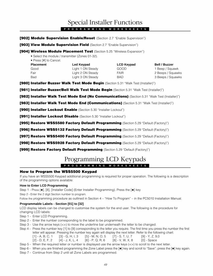
P R O G R A M M I N G W O R K S H E E T S
49
[902] Module Supervision Enable/Reset (Section 2.7 “Enable Supervision”)
[903] View Module Supervision Field (Section 2.7 “Enable Supervision”)
[904] Wireless Module Placement Test (Section 5.25 “Wireless Expansion”)
• Select the module / transmitter (Zones 01-32).• Press [#] to Cancel.Placement Led Keypad LCD Keypad Bell / BuzzerGood Light 1 ON Steady GOOD 1 Beep / SquawkFair Light 2 ON Steady FAIR 2 Beeps / SquawksBad Light 3 ON Steady BAD 3 Beeps / Squawks
[980] Installer Buzzer Walk Test Mode Begin (Section 5.31 “Walk Test (Installer)”)
[981] Installer Buzzer/Bell Walk Test Mode Begin (Section 5.31 “Walk Test (Installer)”)
[982] Installer Walk Test Mode End (No Communications) (Section 5.31 “Walk Test (Installer)”)
[983] Installer Walk Test Mode End (Communications) (Section 5.31 “Walk Test (Installer)”)
[990] Installer Lockout Enable (Section 5.30 “Installer Lockout”)
[991] Installer Lockout Disable (Section 5.30 “Installer Lockout”)
[995] Restore WSS5580 Factory Default Programming (Section 5.29 “Default (Factory)”)
[996] Restore WSS5132 Factory Default Programming (Section 5.29 “Default (Factory)”)
[997] Restore WSS5400 Factory Default Programming (Section 5.29 “Default (Factory)”)
[998] Restore WSS5928 Factory Default Programming (Section 5.29 “Default (Factory)”)
[999] Restore Factory Default Programming (Section 5.29 “Default (Factory)”)
Programming LCD KeypadsP R O G R A M M I N G W O R K S H E E T S
How to Program the WSS5500 KeypadIf you have an WSS5500 Keypad additional programming is required for proper operation. The following is a descriptionof the programming options available:
How to Enter LCD ProgrammingStep 1 - Press [], [8], [Installer Code] (Enter Installer Programming). Press the [] keyStep 2 - Enter the 2 digit Section number to program.
Follow the programming procedure as outlined in Section 4 – “How To Program” – in the PC5010 Installation Manual.
Programmable Labels - Section [01] to [32]LCD display labels can be changed to customise the system for the end user. The following is the procedure forchanging LCD labels:Step 1 - Enter LCD Programming.Step 2 - Enter the number corresponding to the label to be programmed.Step 3 - Use the arrow keys (<>) to move the underline bar underneath the letter to be changed.Step 4 - Press the number key [1] to [9] corresponding to the letter you require. The first time you press the number the first
letter will appear. Pressing the number key again will display the next letter. Refer to the following chart:[1] - A, B, C, 1 [3] - G, H, I, 3 [5] - M, N, O, 5 [7] - S, T, U, 7 [9] - Y, Z, 9,0[2] - D, E, F, 2 [4] - J, K, L, 4 [6] - P, Q, R, 6 [8] - V, W, X, 8 [0] - Space
Step 5 - When the required letter or number is displayed use the arrow keys (<>) to scroll to the next letter.Step 6 - When you are finished programming the Zone Label press the [] key and scroll to “Save”; press the [] key again.Step 7 - Continue from Step 2 until all Zone Labels are programmed.
Special Installer Functions
P R O G R A M M I N G W O R K S H E E T S

P R O G R A M M I N G W O R K S H E E T S
50
NOTE: Zone labels must be no longer than 14 charactersDefault
[01] Zone 1 Label “Zone____1____” I_____I_____I_____I_____I_____I_____I_____I_____I_____I_____I_____I_____I_____I_____I
[02] Zone 2 Label “Zone____2____” I_____I_____I_____I_____I_____I_____I_____I_____I_____I_____I_____I_____I_____I_____I
[03] Zone 3 Label “Zone____3____” I_____I_____I_____I_____I_____I_____I_____I_____I_____I_____I_____I_____I_____I_____I
[04] Zone 4 Label “Zone____4____” I_____I_____I_____I_____I_____I_____I_____I_____I_____I_____I_____I_____I_____I_____I
[05] Zone 5 Label “Zone____5____” I_____I_____I_____I_____I_____I_____I_____I_____I_____I_____I_____I_____I_____I_____I
[06] Zone 6 Label “Zone____6____” I_____I_____I_____I_____I_____I_____I_____I_____I_____I_____I_____I_____I_____I_____I
[07] Zone 7 Label “Zone____7____” I_____I_____I_____I_____I_____I_____I_____I_____I_____I_____I_____I_____I_____I_____I
[08] Zone 8 Label “Zone____8____” I_____I_____I_____I_____I_____I_____I_____I_____I_____I_____I_____I_____I_____I_____I
[09] Zone 9 Label “Zone____9____” I_____I_____I_____I_____I_____I_____I_____I_____I_____I_____I_____I_____I_____I_____I
[10] Zone 10 Label “Zone____10____” I_____I_____I_____I_____I_____I_____I_____I_____I_____I_____I_____I_____I_____I_____I
[11] Zone 11 Label “Zone____11____” I_____I_____I_____I_____I_____I_____I_____I_____I_____I_____I_____I_____I_____I_____I
[12] Zone 12 Label “Zone____12____” I_____I_____I_____I_____I_____I_____I_____I_____I_____I_____I_____I_____I_____I_____I
[13] Zone 13 Label “Zone____13____” I_____I_____I_____I_____I_____I_____I_____I_____I_____I_____I_____I_____I_____I_____I
[14] Zone 14 Label “Zone____14____” I_____I_____I_____I_____I_____I_____I_____I_____I_____I_____I_____I_____I_____I_____I
[15] Zone 15 Label “Zone____15____” I_____I_____I_____I_____I_____I_____I_____I_____I_____I_____I_____I_____I_____I_____I
[16] Zone 16 Label “Zone____16____” I_____I_____I_____I_____I_____I_____I_____I_____I_____I_____I_____I_____I_____I_____I
[17] Zone 17 Label “Zone____17____” I_____I_____I_____I_____I_____I_____I_____I_____I_____I_____I_____I_____I_____I_____I
[18] Zone 18 Label “Zone____18____” I_____I_____I_____I_____I_____I_____I_____I_____I_____I_____I_____I_____I_____I_____I
[19] Zone 19 Label “Zone____19____” I_____I_____I_____I_____I_____I_____I_____I_____I_____I_____I_____I_____I_____I_____I
[20] Zone 20 Label “Zone____20____” I_____I_____I_____I_____I_____I_____I_____I_____I_____I_____I_____I_____I_____I_____I
[21] Zone 21 Label “Zone____21____” I_____I_____I_____I_____I_____I_____I_____I_____I_____I_____I_____I_____I_____I_____I
[22] Zone 22 Label “Zone____22____” I_____I_____I_____I_____I_____I_____I_____I_____I_____I_____I_____I_____I_____I_____I
[23] Zone 23 Label “Zone____23____” I_____I_____I_____I_____I_____I_____I_____I_____I_____I_____I_____I_____I_____I_____I
[24] Zone 24 Label “Zone____24____” I_____I_____I_____I_____I_____I_____I_____I_____I_____I_____I_____I_____I_____I_____I
[25] Zone 25 Label “Zone____25____” I_____I_____I_____I_____I_____I_____I_____I_____I_____I_____I_____I_____I_____I_____I
[26] Zone 26 Label “Zone____26____” I_____I_____I_____I_____I_____I_____I_____I_____I_____I_____I_____I_____I_____I_____I
[27] Zone 27 Label “Zone____27____” I_____I_____I_____I_____I_____I_____I_____I_____I_____I_____I_____I_____I_____I_____I
[28] Zone 28 Label “Zone____28____” I_____I_____I_____I_____I_____I_____I_____I_____I_____I_____I_____I_____I_____I_____I
[29] Zone 29 Label “Zone____29____” I_____I_____I_____I_____I_____I_____I_____I_____I_____I_____I_____I_____I_____I_____I
[30] Zone 30 Label “Zone____30____” I_____I_____I_____I_____I_____I_____I_____I_____I_____I_____I_____I_____I_____I_____I
[31] Zone 31 Label “Zone____31____” I_____I_____I_____I_____I_____I_____I_____I_____I_____I_____I_____I_____I_____I_____I
[32] Zone 32 Label “Zone____32____” I_____I_____I_____I_____I_____I_____I_____I_____I_____I_____I_____I_____I_____I_____I
[33] Fire Alarm Label “Fire_Zone____” I_____I_____I_____I_____I_____I_____I_____I_____I_____I_____I_____I_____I_____I_____I
[40] Utility Output Label “Utility_Output” I_____I_____I_____I_____I_____I_____I_____I_____I_____I_____I_____I_____I_____I_____I
[44] Sensor Reset Label “Sensor_Reset__” I_____I_____I_____I_____I_____I_____I_____I_____I_____I_____I_____I_____I_____I_____I
[51] Fail to Arm Event “System_Has______ I_____I_____I_____I_____I_____I_____I_____I_____I_____I_____I_____I_____I_____I_____I
Message Failed_to_Arm___” I_____I_____I_____I_____I_____I_____I_____I_____I_____I_____I_____I_____I_____I_____I
[52] Alarm When Armed “Alarm_Occurred__ I_____I_____I_____I_____I_____I_____I_____I_____I_____I_____I_____I_____I_____I_____I
Event Message While_Armed_____” I_____I_____I_____I_____I_____I_____I_____I_____I_____I_____I_____I_____I_____I_____I
[60] First User Display MaskDefault Option ON OFFON I_______I 11111 Hold [P] Keys prompt ON Hold [P] Keys prompt OFFON I_______I 22222 Zone Bypassing prompt ON Zone Bypass prompt OFFON I_______I 33333 Troubles prompt ON Troubles prompt OFFON I_______I 44444 Alarm Memory prompt ON Alarm Memory prompt OFFON I_______I 55555 Access Codes prompt ON Access Codes prompt OFFON I_______I 66666 User Functions prompt ON User Functions prompt OFFON I_______I 77777 Output Control prompt ON Output Control prompt OFFOFF I_______I 88888 Installer Programming prompt ON Installer Programming prompt OFF

51
P R O G R A M M I N G W O R K S H E E T S
[61] Second User Display MaskDefault Option ON OFFON I_______I 11111 View Event Buffer prompt ON View Event Buffer prompt OFFOFF I_______I 22222 System Test prompt ON System Test prompt OFFON I_______I 33333 Time and Date prompt ON Time and Date prompt OFFOFF I_______I 44444 User Call-up prompt ON User Call-up prompt OFFON I_______I 55555 Bright Control prompt ON Bright Control prompt OFFON I_______I 66666 Contrast Control prompt ON Contrast Control prompt OFFON I_______I 77777 Buzzer Control prompt ON Buzzer Control prompt OFFOFF I_______I 88888 For Future Use
[62] Third User Display MaskDefault Option ON OFFON I_______I 11111 Interior Arm prompt ON Interior Arm prompt OFFON I_______I 22222 No Entry Delay prompt ON No Entry Delay prompt OFFOFF I_______I 3-83-83-83-83-8 For Future Use
[63] Downloaded LCD Message DurationDefault (Valid entries are 000-255, 000=Unlimited Message Display.003 I______I______I______I This number represents the number of times the Downloaded message is cleared by
pressing any key while the message is up after timeout)[64] Key OptionsDefault Option ON OFFON I_______I 11111 [F] Keys enabled Fire Keys disabledON I_______I 22222 [A] Keys enabled Auxiliary Keys disabledON I_______I 33333 [P] Keys enabled Panic Keys disabled
OFF I_______I 4-84-84-84-84-8 For Future Use[66] Keypad OptionsDefault Option ON OFFON I_______I 11111 Display Access Code when Programming Display ‘X’ when ProgrammingON I_______I 22222 Local Clock Display Enabled Local Clock Display Disabled
OFF I_______I 3-83-83-83-83-8 For Future Use
[97] View Software Version
[98] Initiate Global Label BroadcastAll LCD programming is done by keypad. If more than one LCD keypad is present it is not necessary to programeach independently. Labels programmed in one keypad can be broadcast to all other LCD keypads. Thefollowing is the procedure for broadcasting labels:Step 1 - Program one LCD keypad completely.Step 2 - Make sure all LCD keypads are connected to the Keybus.Step 3 - Enter LCD Programming at the keypad that was programmed.Step 4 - Enter Section [98] at the keypad that was programmed. The keypad will now broadcast all the informationprogrammed to all the other LCD keypads on the system. When the keypad is finished press the [#] key to exit.
[99] Factory Default LCD KeypadThe following is the procedure for restoring an LCD keypad to the factory default settings:• Enter Installer Programming at the keypad to be defaulted. Enter Section [99].• When the keypad is finished defaulting press the [#] key to exit programming.
ASCII Characters
032
064 176
240
033
225
241
034
035
036
228
244
038
230
246
039
231
040
248
041
249
042 058 234
043 059 123
044 060 124
236
045 061
093
125
253
046 062
094
126
238047 063
095
127
239
255
254
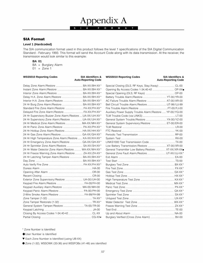
SIA FormatLevel 1 (Hardcoded)
The SIA communication format used in this product follows the level 1 specifications of the SIA Digital CommunicationStandard - February 1993. This format will send the Account Code along with its data transmission. At the receiver, thetransmission would look similar to this example:
BA 01BA = Burglary Alarm01 = Zone 1
WSS5010 Reporting Codes SIA Identifiers &Auto-Reporting Code
Delay Zone Alarm/Restore .................................... BA-XX/BH-XX *Instant Zone Alarm/Restore .................................. BA-XX/BH-XX *Interior Zone Alarm/Restore .................................. BA-XX/BH-XX *Delay H.A. Zone Alarm/Restore ............................ BA-XX/BH-XX *Interior H.A. Zone Alarm/Restore .......................... BA-XX/BH-XX *24 Hr Burg Zone Alarm/Restore ............................ BA-XX/BH-XX *Standard Fire Zone Alarm/Restore ........................ FA-XX/FH-XX *Delayed Fire Zone Alarm/Restore .......................... FA-XX/FH-XX *24 Hr Supervisory Buzzer Zone Alarm/Restore ....UA-XX/UH-XX *24 Hr Supervisory Zone Alarm/Restore ................UA-XX/UH-XX *24 Hr Medical Zone Alarm/Restore ...................... MA-XX/MH-XX *24 Hr Panic Zone Alarm/Restore .......................... PA-XX/PH-XX *24 Hr Holdup Zone Alarm/Restore ........................HA-XX/HH-XX *24 Hr Gas Zone Alarm/Restore ............................ GA-XX/GH-XX *24 Hr High Temperature Zone Alarm/Restore ...... KA-XX/KH-XX *24 Hr Emergency Zone Alarm/Restore ................ QA-XX/QH-XX *24 Hr Sprinkler Zone Alarm/Restore ..................... SA-XX/SH-XX *24 Hr Water Detector Zone Alarm/Restore ......... WA-XX/WH-XX *24 Hr Freeze Warning Zone Alarm/Restore .......... ZA-XX/ZH-XX *24 Hr Latching Tamper Alarm/Restore ................. BA-XX/BH-XX *Day Zone ................................................................ BA-XX/BH-XX *Auto Verify Fire Zone ............................................... FA-XX/FH-XX *Duress Alarm ....................................................................... HA-00Opening After Alarm ...........................................................OR-00Recent Closing .................................................................... CR-00Exterior Zone Supervisory /Restore ....................... UA-00/UH-00Keypad Fire Alarm/Restore ..................................... FA-00/FH-00Keypad Auxiliary Alarm/Restore .......................... MA-00/MH-00Keypad Panic Alarm/Restore ................................. PA-00/PH-002-Wire Smoke Alarm/Restore .................................. FA-99/FH-99Zone Tamper (1-32) ............................................................ TA-XX *Zone Tamper Restorals (1-32) ............................................ TR-XX *General System Tamper/Restore ............................ TA-00/TR-00Keypad Latching ................................................................. JA-00Closing By Access Codes 1-34,40-42 ................................ CL-XXPartial Closing .................................................................... CG-XX
52
Appendix AS I A F O R M A T
WSS5010 Reporting Codes SIA Identifiers &Auto-Reporting Code
Special Closing (DLS, RF Keys, Stay /Away) ..................... CL-00Opening By Access Codes 1-34,40-42 ............................. OP-XX
Special Opening (DLS, RF Keys) ....................................... OP-00Battery Trouble Alarm/Restore ................................ YT-00/YR-00AC Failure Trouble Alarm/Restore ......................... AT-00/AR-00Bell Circuit Trouble Alarm/Restore ..........................UT-99/UJ-99Fire Trouble Alarm/Restore ...................................... FT-00/FJ-00Auxiliary Power Supply Trouble Alarm/Restore ..... YP-00/YQ-00TLM Trouble Code (via LINKS) ............................................ LT-00General System Trouble/Restore ............................ YX-00/YZ-00General System Supervisory /Restore ..................... ET-00/ER-00TLM Restoral ....................................................................... LR-00FTC Restoral ........................................................................ YK-00Periodic Test Transmission ................................................. RP-00System Test ......................................................................... RX-00LINKS1000 Test Transmission Code ................................... TX-00Low Battery Transmission/Restore ......................... XT-00/XR-00General Transmitter Low Battery /Restore .............. XT-XX/XR-XX
General Zone Fault Alarm/Restore ......................... UT-XX/UJ-XX *Exit Alarm ............................................................................ EA-00Test Start .............................................................................. TS-00Burglary Test Zone .............................................................. BX-XX*Fire Test Zone ...................................................................... FX-XX*Gas Test Zone .................................................................... GX-XX*Holdup Test Zone ................................................................ HX-XX *High Temperature Test Zone .............................................. KX-XX*Medical Test Zone .............................................................. MX-XX *Panic Test Zone ................................................................... PX-XX *Emergency Test Zone ........................................................ QX-XX*Sprinkler Test Zone ............................................................. SX-XX *Untyped Test Zone ..............................................................UX-XX *Water Detector Test Zone ................................................. WX-XX*Freeze Warning Test Zone .................................................. ZX-XX *Test End ................................................................................ TE-00Up and About Alarm ........................................................... NA-00Burglary Verified (Cross Zone Alarm) ................................. BV-00
* Zone Number is Identified
User Number is Identified
Each Zone Number is Identified (using UB-XX)
Zone (1-32), WSSOWK (33-36) and WSSFOBs (41-48) are identified

Pager FormatIf the pager option is enabled by the installer, the pager reporting code may report to the pager.
Pager Reporting CodesClosing By User 01 ............. 01Closing By User 02 ............. 02Closing By User 03 ............. 03Closing By User 04 ............. 04Closing By User 05 ............. 05Closing By User 06 ............. 06Closing By User 07 ............. 07Closing By User 08 ............. 08Closing By User 09 ............. 09Closing By User 10 ............. 10Closing By User 11 ............. 11Closing By User 12 ............. 12Closing By User 13 ............. 13Closing By User 14 ............. 14Closing By User 15 ............. 15Closing By User 16 ............. 16Closing By User 17 ............. 17Closing By User 18 ............. 18Closing By User 19 ............. 19Closing By User 20 ............. 20Closing By User 21 ............. 21Closing By User 22 ............. 22Closing By User 23 ............. 23Closing By User 24 ............. 24Closing By User 25 ............. 25Closing By User 26 ............. 26Closing By User 27 ............. 27Closing By User 28 ............. 28Closing By User 29 ............. 29Closing By User 30 ............. 30Closing By User 31 ............. 31Closing By User 32 ............. 32Closing By User 33 ............. 33Closing By User 34 ............. 34Closing By User 40 ............. 35Closing By User 41 ............. 36Closing By User 42 ............. 37
53
Appendix BP A G E R F O R M A T
Opening By User 01 ............. 51Opening By User 02 ............. 52Opening By User 03 ............. 53Opening By User 04 ............. 54Opening By User 05 ............. 55Opening By User 06 ............. 56Opening By User 07 ............. 57Opening By User 08 ............. 58Opening By User 09 ............. 59Opening By User 10 ............. 60Opening By User 11 ............. 61Opening By User 12 ............. 62Opening By User 13 ............. 63Opening By User 14 ............. 64Opening By User 15 ............. 65Opening By User 16 ............. 66Opening By User 17 ............. 67Opening By User 18 ............. 68Opening By User 19 ............. 69Opening By User 20 ............. 70Opening By User 21 ............. 71Opening By User 22 ............. 72Opening By User 23 ............. 73Opening By User 24 ............. 74Opening By User 25 ............. 75Opening By User 26 ............. 76Opening By User 27 ............. 77Opening By User 28 ............. 78Opening By User 29 ............. 79Opening By User 30 ............. 80Opening By User 31 ............. 81Opening By User 32 ............. 82Opening By User 33 ............. 83Opening By User 34 ............. 84Opening By User 40 ............. 85Opening By User 41 ............. 86Opening By User 42 ............. 87
Special Closing (DLS, Wireless Key) ....... 00Special Opening (DLS, Wireless Key) ..... 50
AC Failure Trouble Alarm ......................... 91AC Failure Trouble Restore ...................... 92
General System Event .............................. 90Zone Alarms (Zones 1-32)Duress AlarmZone Expander Supervisory AlarmKeypad [F]ire AlarmKeypad [A]uxiliary AlarmKeypad [P]anic Alarm2-Wire Smoke AlarmOpening After AlarmUp and About AlarmZone Tamper (1-32)General System Tamper
The following events will NOT be transmitted to the Pager.Zone XX BypassZone XX TestTest BeginTest EndZone Alarm Restorals (zones 1-32)Recent ClosingZone Tamper Restorals (1-32)Keypad LockoutPartial ClosingBattery Trouble Alarm/RestoreBell Circuit Trouble Alarm/Restore
Fire Trouble Alarm/RestoreAuxiliary Power Supply Trouble Alarm/RestoreTLM Trouble Code (via LINKS)General System Trouble/RestoreGeneral System Supervisory /RestoreTLM RestoralPhone Number 1 FTCPeriodic Test TransmissionSystem TestLINKS1000 Test Transmission Code
Transmitter Low Battery /RestoreZone Trouble/RestoreBurglary Verified (Cross Zone Alarm)Exit AlarmZone Expander Supervisory RestoralKeypad [F]ire RestoralKeypad [A]uxiliary RestoralKeypad [P]anic Restoral2-Wire Smoke RestoralGeneral System Tamper Restoral

Hookup DiagramW S S 5 0 1 0 C O N T R O L P A N E L
54

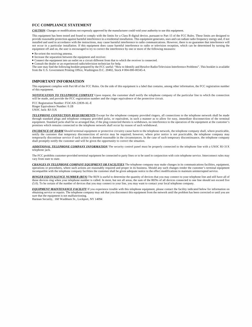
FCC COMPLIANCE STATEMENTCAUTION: Changes or modifications not expressly approved by the manufacturer could void your authority to use this equipment.
This equipment has been tested and found to comply with the limits for a Class B digital device, pursuant to Part 15 of the FCC Rules. These limits are designed toprovide reasonable protection against harmful interference in a residential installation. This equipment generates, uses and can radiate radio frequency energy and, if notinstalled and used in accordance with the instructions, may cause harmful interference to radio communications. However, there is no guarantee that interference willnot occur in a particular installation. If this equipment does cause harmful interference to radio or television reception, which can be determined by turning theequipment off and on, the user is encouraged to try to correct the interference by one or more of the following measures:
Re-orient the receiving antenna. Increase the separation between the equipment and receiver. Connect the equipment into an outlet on a circuit different from that to which the receiver is connected. Consult the dealer or an experienced radio/television technician for help.The user may find the following booklet prepared by the FCC useful: “How to Identify and Resolve Radio/Television Interference Problems”. This booklet is availablefrom the U.S. Government Printing Office, Washington D.C. 20402, Stock # 004-000-00345-4.
IMPORTANT INFORMATIONThis equipment complies with Part 68 of the FCC Rules. On the side of this equipment is a label that contains, among other information, the FCC registration numberof this equipment.
NOTIFICATION TO TELEPHONE COMPANY Upon request, the customer shall notify the telephone company of the particular line to which the connectionwill be made, and provide the FCC registration number and the ringer equivalence of the protective circuit.
FCC Registration Number: F53CAN-22839-AL-ERinger Equivalence Number: 0.1BUSOC Jack: RJ-31X
TELEPHONE CONNECTION REQUIREMENTS Except for the telephone company provided ringers, all connections to the telephone network shall be madethrough standard plugs and telephone company provided jacks, or equivalent, in such a manner as to allow for easy, immediate disconnection of the terminalequipment. Standard jacks shall be so arranged that, if the plug connected thereto is withdrawn, no interference to the operation of the equipment at the customer’spremises which remains connected to the telephone network shall occur by reason of such withdrawal.
INCIDENCE OF HARM Should terminal equipment or protective circuitry cause harm to the telephone network, the telephone company shall, where practicable,notify the customer that temporary disconnection of service may be required; however, where prior notice is not practicable, the telephone company maytemporarily discontinue service if such action is deemed reasonable in the circumstances. In the case of such temporary discontinuance, the telephone companyshall promptly notify the customer and will be given the opportunity to correct the situation.
ADDITIONAL TELEPHONE COMPANY INFORMATION The security control panel must be properly connected to the telephone line with a USOC RJ-31Xtelephone jack.
The FCC prohibits customer-provided terminal equipment be connected to party lines or to be used in conjunction with coin telephone service. Interconnect rules mayvary from state to state.
CHANGES IN TELEPHONE COMPANY EQUIPMENT OR FACILITIES The telephone company may make changes in its communications facilities, equipment,operations or procedures, where such actions are reasonably required and proper in its business. Should any such changes render the customer’s terminal equipmentincompatible with the telephone company facilities the customer shall be given adequate notice to the effect modifications to maintain uninterrupted service.
RINGER EQUIVALENCE NUMBER (REN) The REN is useful to determine the quantity of devices that you may connect to your telephone line and still have all ofthose devices ring when your telephone number is called. In most, but not all areas, the sum of the RENs of all devices connected to one line should not exceed five(5.0). To be certain of the number of devices that you may connect to your line, you may want to contact your local telephone company.
EQUIPMENT MAINTENANCE FACILITY If you experience trouble with this telephone equipment, please contact the facility indicated below for information onobtaining service or repairs. The telephone company may ask that you disconnect this equipment from the network until the problem has been corrected or until you aresure that the equipment is not malfunctioning.Harman Security, 160 Washburn St., Lockport, NY 14094

Westar Security Services1-800-654-6770
Printed in North America 29002434 R1