wsn nodes for health monotoring of players on football field through collaborative communication
TRANSCRIPT

WSN Nodes for Health Monitoring of Players on
Football Field Through Collaborative Communication
B.Eng. (Hons.) Electrical (Telecom) Engineering
Abdul Mannan DDP-FA11-BTE-145
Shan-e-Fazal-e-Haq DDP-FA11-BTE-123
Abdul Qadir Chauhan DDP-FA11-BTE-127
M. Osman Riaz DDP-FA11-BTE-094
Project Advisor: Dr. Ali Nawaz Khan
COMSATS-LANCASTER Dual Degree Program
COMSATS INSTITUTE OF INFORMATION
TECHNOLOGY, LAHORE, PAKISTAN

Submission Form for FYP Report
COMSATS Institute of Information Technology, Lahore Campus Department of Electrical Engineering
PROJECT ID 05 NUMBER OF
MEMBERS 04
TITLE WSN Nodes for Health Monitoring of Players on Football Field Through
Collaborative Communication
SUPERVISOR NAME Dr. Ali Nawaz Khan
MEMBER NAME CIIT REG. NO. LU ID. EMAIL ADDRESS
Abdul Mannan DDP-FA11-BTE-145
33065292 [email protected]
Shan-e-Fazal-e-Haq DDP-FA11-BTE-123
33065270 [email protected]
Abdul Qadir Chauhan DDP-FA11-BTE-127
33065274 [email protected]
M. Osman Riaz DDP-FA11-BTE-094
33065241 [email protected]
CHECKLIST:
Number of pages in this report 84
I/We have enclosed the soft-copy of this document along-with the
codes and scripts created by myself/ourselves YES / NO
My/Our supervisor has attested the attached document YES / NO
I/We confirm to state that this project is free from any type of
plagiarism and misuse of copyrighted material YES / NO
MEMBERS’ SIGNATURES
Supervisor’s Signature

i
This work, entitled “WSN Nodes for Health Monitoring of Players on Football Field
Through Collaborative Communication” has been approved for the award of
B. Eng. (Hons.) in Electrical (Telecommunication)
Engineering
Spring 2015
External Examiner:
Head of Department:
Department of Electrical Engineering
COMSATS INSTITUTE OF INFORMATION TECHNOLOGY LAHORE – PAKISTAN

ii
DECLARATION
“No portion of the work referred to in the dissertation has been submitted in support of an
application for another degree or qualification of this or any other university/institute or other
institution of learning”.
MEMBERS’ SIGNATURES

iii
ACKNOWLEDGEMENTS
In the name of Almighty Allah, the most kind and most merciful. We are grateful to Almighty
Allah who provides us with all the resources, so that we make their proper use for the benefit of
mankind. We would like to extend our immense gratitude towards our parents and family members
who kept backing us up in all the times, both financially and morally.
We are tremendously thankful and highly obliged to our project supervisor as well as mentor Dr.
Ali Nawaz Khan for his guidance, enlightenment and encouragement to work hard and smart. We
have found him supremely helpful while discussing the optimization issues in this dissertation as
well as practical work. His critical comments on our work have certainly made us think of new
ideas and techniques in the fields of optimization as well as hardware/ software integration and
simulation.
We are eminently grateful to all of our group members who efficiently managed to complete this
project within the given time. This project could not be completed without the individual efforts
and team co-operation from our group members, Mr. Abdul Qadir Chauhan, Mr. Shan-e-Fazal,
Mr. Abdul Mannan and Mr. Muhammad Osman Riaz.
We would like to express our recognition and appreciation towards the staff as well as facilities
provided to us in final year project lab. We also eulogize our friends and respondents for their
support and willingness to spend some of their valuable time with us to fill in the questionnaires
that proved to be very helpful for the fulfilment of our goal. However, this project would not have
been possible without the kind support and help of many individuals and experts, we would like
to extend our sincere regard to all of them.

iv
ABSTRACT
Wireless Sensor Networks (WSNs) consist of spatially distributed autonomous devices which are
capable of; interacting with their environment through various sensors, processing gathered
information and communicating this information wirelessly with their neighbour nodes. We have
designed an ad-hoc system that can be used for continuous measurement and observation of the
football player’s physiological and location statistics (e.g. heart rate, blood pressure, temperature,
speed etc.) through bio-medical sensors attached to a wearable kit and creating a sophisticated
wireless sensor network (WSN) to transport this data back to the sink/ base station node through
collaborative communication for further processing. By assessing the acquired statistics for the
purpose of guiding management decisions, including when to make therapeutic interventions and
assessment of those interventions, the designed and implemented ad-hoc system shall prove to be
a life saver for the football player’s on the field.

v
Table of Contents
1 INTRODUCTION ............................................................................................................................. 2
1.1 WIRELESS SENSOR NETWORKS ..................................................................................................................... 2
1.1.1 Energy Efficient Operation ...................................................................................................................... 2
1.1.2 WSN Anatomy .......................................................................................................................................... 2
1.2 DESIGN CHALLENGES ................................................................................................................................... 3
1.2.1 WSN Deployment ..................................................................................................................................... 3
1.2.2 Spatial-Temporal Correlation of WSNs ................................................................................................... 3
1.3 APPLICATIONS OF WSNS .............................................................................................................................. 4
1.3.1 Health Applications ................................................................................................................................. 4
1.3.2 Artificial Retina Project ........................................................................................................................... 4
1.3.3 Patient Monitoring System ....................................................................................................................... 5
1.4 DISSERTATION OUTLINE ............................................................................................................................... 6
2 LITERATURE REVIEW ................................................................................................................. 8
2.1 HETEROGENEOUS WIRELESS SENSOR NETWORKS ........................................................................................ 8
2.2 NETWORK ARCHITECTURE............................................................................................................................ 9
2.2.1 Single-Tier Architectures in WSNs .......................................................................................................... 9
2.2.2 Multi-Tier Architectures in WSNs .......................................................................................................... 10
2.3 DESIGN FACTORS OF HETEROGENEOUS WSNS ........................................................................................... 11
2.3.1 Heterogeneous Traffic Source Coding ................................................................................................... 11
2.3.2 Application-Specific Quality of Services................................................................................................ 11
2.3.3 Increased Bandwidth Demand ............................................................................................................... 12
2.3.4 Heterogeneous Traffic In-Network Processing ...................................................................................... 12
2.3.5 Efficient Energy Consumption ............................................................................................................... 12
2.3.6 WSN Resource Constraints .................................................................................................................... 13
2.3.7 Coverage Range ..................................................................................................................................... 13
2.3.8 Functional Cross-Layer Coupling ......................................................................................................... 13
2.3.9 Variable Channel Capacity ................................................................................................................... 14
2.4 WSN COVERAGE ........................................................................................................................................ 14
2.4.1 WSN Range ............................................................................................................................................ 14
2.4.2 WSN Directivity ..................................................................................................................................... 15
2.4.3 WSN Line of Sight .................................................................................................................................. 15
2.4.4 WSN Dynamic View ............................................................................................................................... 15
2.5 HETEROGENEOUS SENSOR HARDWARE ...................................................................................................... 16
2.5.1 Battery-less and Wireless Wearable Microphones ................................................................................ 16
2.5.2 Mic-on-board Sensor Board .................................................................................................................. 17

vi
2.6 LOW-RESOLUTION VIDEO SENSORS ............................................................................................................ 18
2.6.1 Cyclops Video Sensors ........................................................................................................................... 18
2.6.2 CMUcam Camera Systems .................................................................................................................... 19
2.6.3 MeshEye Video Sensor ........................................................................................................................... 20
2.7 MEDIUM-RESOLUTION VIDEO SENSORS ..................................................................................................... 20
2.7.1 Panoptes Video Sensor .......................................................................................................................... 21
2.7.2 GARCIA A Mobile Robot Video Sensor ................................................................................................. 21
2.8 EXAMPLES OF DEPLOYED MULTIMEDIA SENSOR NETWORKS ..................................................................... 22
2.8.1 SensEye Testbed Platform ..................................................................................................................... 22
2.8.2 Meerkats Testbed Platform .................................................................................................................... 23
2.8.3 IrisNet Software Platform ...................................................................................................................... 24
3 DESIGN CHALLENGES ............................................................................................................... 27
3.1 METHODOLOGY .......................................................................................................................................... 27
3.1.1 Collaborative Communication ............................................................................................................... 27
3.1.2 System Diagram ..................................................................................................................................... 28
3.2 HARDWARE COMPONENTS .......................................................................................................................... 29
3.2.1 Processing Unit [34] ............................................................................................................................. 29
3.2.2 Communication Sensor [35] .................................................................................................................. 29
3.2.3 Location Sensor [36] ............................................................................................................................. 30
3.2.4 Pulse Sensor [37] .................................................................................................................................. 31
3.2.5 Digital Temperature Sensor [38] ........................................................................................................... 31
3.3 SOFTWARE ARCHITECTURE ........................................................................................................................ 32
3.3.1 Hardware/ Software Configuration and Integration ............................................................................. 32
3.3.2 XBEE Configuration .............................................................................................................................. 33
3.3.3 Android Mobile App............................................................................................................................... 34
3.3.4 App Development Procedure ................................................................................................................. 34
3.3.5 Microsoft SQL Server Database ............................................................................................................ 37
4 TESTING AND RESULTS ............................................................................................................ 39
4.1 WEARABLE HARDWARE DESIGN ................................................................................................................ 39
4.2 COMMUNICATION ASPECTS ........................................................................................................................ 39
4.2.1 Line of Sight Communication (LOS) ...................................................................................................... 39
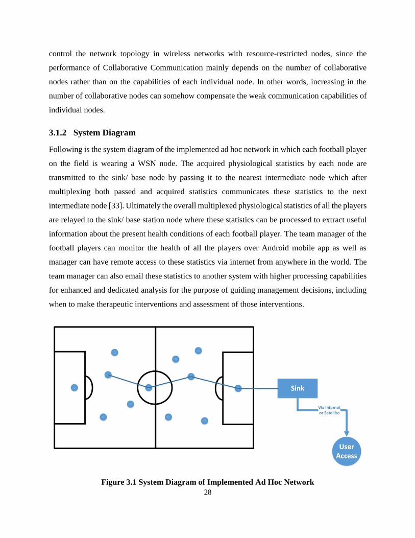
4.2.2 Non-Line of Sight Communication (NLOS) ........................................................................................... 40
4.3 INTEGRATED HARDWARE/ SOFTWARE DESIGN ........................................................................................... 41
4.3.1 Final Deliverable ................................................................................................................................... 41
4.3.2 Features ................................................................................................................................................. 41
5 CONCLUSIONS AND FUTURE WORK ..................................................................................... 44

vii
5.1 CONCLUSIONS ............................................................................................................................................. 44
5.2 FUTURE WORK ........................................................................................................................................... 45
APPENDIX A: C SOURCE CODE ........................................................................................................ 50
APPENDIX B: HARDWARE SCHEMATICS ..................................................................................... 82
APPENDIX C: LIST OF COMPONENTS ............................................................................................ 83
APPENDIX D: PROJECT TIMELINE ................................................................................................. 84

v
Table of Figures
FIGURE 1-1 OPERATING PRINCIPLE OF THE ARTIFICIAL RETINA ..................................................................... 5
FIGURE 1-2 MEDICAL SENSOR NODES USED IN CODEBLUE ............................................................................ 5
FIGURE 2-1 ARCHITECTURE OF HETEROGENEOUS WSNS ........................................................................... 10
FIGURE 2-2 DEPICTION OF THE COVERAGE IN WSNS .................................................................................. 16
FIGURE 2-3 MTS310 SENSOR BOARD ......................................................................................................... 17
FIGURE 2-4 CYCLOPS VIDEO SENSOR MOTE ............................................................................................... 19
FIGURE 2-5 HIERARCHY OF INTEGERATED CMUCAM CAMERA SYSTEMS ................................................... 19
FIGURE 2-6 MESHEYE VIDEO SENSOR MOTE .............................................................................................. 20
FIGURE 2-7 PANOPTES VIDEO SENSOR PLATFORM ...................................................................................... 21
FIGURE 2-8 GARCIA MOBILE ROBOT INTEGRATED WITH PAN–TILT CAMERA .......................................... 22
FIGURE 2-9 SENSEYE: MULTI-TIER ARCHITECTURE DEPICTION .................................................................. 23
FIGURE 2-10 GRAPH DEPICTING AVERAGE CURRENT CONSUMPTION FOR VARIOUS TASKS ....................... 24
FIGURE 3-1 SYSTEM DIAGRAM OF IMPLEMENTED AD HOC NETWORK ........................................................ 28
FIGURE 3-2 ARDUINO MEGA 2560 MCU BOARD ........................................................................................ 29
FIGURE 3-3 ZIGBEE BASED XBEE SERIES 2 MODULE ................................................................................. 30
FIGURE 3-4 SKM53 GPS MODULE ............................................................................................................. 31
FIGURE 3-5 SEN-11574 - PULSE SENSOR .................................................................................................... 31
FIGURE 3-6 DS18B20 - A 1-WIRE DIGITAL TEMPERATURE SENSOR ........................................................... 32
FIGURE 3-7 X-CTU SOFTWARE ................................................................................................................... 33
FIGURE 3-8 ANDROID BASED MOBILE APP ................................................................................................. 36
FIGURE 3-9 MICROSOFT SQL SERVER MANAGEMENT STUDIO ................................................................... 37
FIGURE 4-1 LOS AND NLOS TRANSMISSION UNDER NORMAL CONDITIONS .............................................. 40
FIGURE 4-2 LOS AND NLOS TRANSMISSION DURING COLLABORATIVE COMMUNICATION ....................... 40
FIGURE 4-3 WEARABLE WSN KIT............................................................................................................... 42
FIGURE 5-1 PIE CHART DEPICTING BATTERY CONSUMED BY VARIOUS TASKS IN WSN NODE ................... 45

vi
List of Tables
TABLE 1-1 APPLICATIONS OF WSNS ............................................................................................................. 4
TABLE 2-1 SPECIFICATIONS OF VIDEO SENSORS .......................................................................................... 18
TABLE 3-1 PERFORMANCE SPECIFICATIONS OF XBEE SERIES 2 MODULE ................................................... 30

1
CHAPTER 1
INTRODUCTION

2
1 INTRODUCTION
1.1 Wireless Sensor Networks
Wireless Sensor Networks (WSNs) consist of tiny sensing nodes, which can act as both data
generators as well as network relays. Each node consists of a microprocessor, sensor(s), and a
transceiver and is capable of interacting with its environment through various sensors, processing
gathered information and communicating this information wirelessly with their neighbour nodes.
Sensor nodes can be programmed to accomplish complex tasks rather than transmitting only what
they observe through on-board microprocessors. To communicate the observed phenomena of
interest the transceiver provides wireless connectivity. Sensor nodes are powered by limited
capacity batteries and are generally stationary [1]. Selected wireless protocol depends on
application requirement. Some of the available standards include IEEE 802.15.4(LR-WPANs),
IEEE 802.11(WLAN) [2] standard, Bluetooth or proprietary radios, which usually operate around
900 MHz.
1.1.1 Energy Efficient Operation
To save energy, nodes aggressively switch their transceivers off and essentially become
disconnected from the network. Therefore, although the locations of the nodes do not change, the
network topology dynamically changes due to the power management activities of the sensor
nodes. It is a major challenge to provide connectivity of the network while minimizing the energy
consumption in this dynamic environment. The energy-efficient operation of WSNs, however,
provides significantly long lifetimes that surpass any system that relies on batteries [3].
Wireless communications, and digital electronics, the design and development of low-power, low-
cost, multifunctional sensor nodes that are small in size and communicate untethered in short
distances have become feasible with the recent advances in micro electro-mechanical systems
(MEMS) technology [1].
1.1.2 WSN Anatomy
The realization of wireless sensor networks (WSNs) based on the collaborative effort of a large
number of sensor nodes which include sensing, data processing, and communicating, enable the
ever-increasing capabilities of these tiny sensor nodes. Sophisticated and extremely efficient

3
communication protocols are required in order to realize the existing and potential applications for
WSNs [4]. WSNs are composed of a large number of sensor nodes, which are densely deployed
either inside a physical phenomenon or very close to it. In order to enable reliable and efficient
observation and to initiate the right actions, physical features of the phenomenon should be reliably
detected/estimated from the collaborative information provided by the sensor nodes.
1.2 Design Challenges
Sensor nodes use their processing capabilities to locally carry out simple computations and
transmit only the required and partially processed data, instead of sending the raw data to the nodes
responsible for the fusion. Hence, unique challenges for the development of communication
protocols are presented by these properties of WSNs.
Additional challenges are posed to the communication protocols in terms of energy consumption
due to the intrinsic properties of individual sensor nodes [1]. As Sensor nodes carry limited power
sources therefore WSN applications and communication protocols are mainly tailored to provide
high energy efficiency while traditional networks are designed to improve performance metrics
such as throughput and delay, WSN protocols focus primarily on power conservation.
1.2.1 WSN Deployment
Another factor that is considered in developing WSN protocols is the deployment of WSNs. The
position of the sensor nodes need not be engineered or predetermined permitting random
deployment in inaccessible terrains or disaster relief operations. Besides the development of self-
organizing protocols for the communication protocol stack is required for this random deployment.
The density in the network is also exploited in WSN protocols in addition to the placement of
nodes. Neighbouring nodes may be very close to each other due to dense deployment of large
numbers of sensor nodes and short transmission ranges.
1.2.2 Spatial-Temporal Correlation of WSNs
Since multi-hop communication leads to less power consumption than the traditional single hop
communication hence, it is exploited in communications between WSN nodes. Furthermore, the
spatio-temporal correlation-based protocols emerged for improved efficiency in networking
wireless sensors as a result of the introduction of correlation in spatial and temporal domains of
the dense deployment coupled with the physical properties of the sensed phenomenon.
4
1.3 Applications of WSNs
WSNs have a wide range of applications in various fields of life [5, 6, 7]. A considerable amount
of research in the last decade, has enabled the actual implementation and deployment of sensor
networks tailored to the unique requirements of certain sensing and monitoring applications. In
accordance with our vision, WSNs are slowly becoming an integral part of our lives [8, 9, 10].
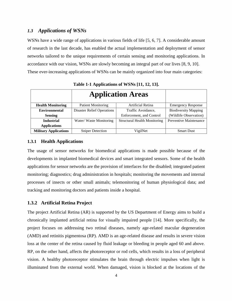
These ever-increasing applications of WSNs can be mainly organized into four main categories:
Table 1-1 Applications of WSNs [11, 12, 13].
Application Areas
Health Monitoring Patient Monitoring Artificial Retina Emergency Response
Environmental
Sensing
Disaster Relief Operations Traffic Avoidance,
Enforcement, and Control
Biodiversity Mapping
(Wildlife Observation)
Industrial
Applications
Water/ Waste Monitoring Structural Health Monitoring Preventive Maintenance
Military Applications Sniper Detection VigilNet Smart Dust
1.3.1 Health Applications
The usage of sensor networks for biomedical applications is made possible because of the
developments in implanted biomedical devices and smart integrated sensors. Some of the health
applications for sensor networks are the provision of interfaces for the disabled; integrated patient
monitoring; diagnostics; drug administration in hospitals; monitoring the movements and internal
processes of insects or other small animals; telemonitoring of human physiological data; and
tracking and monitoring doctors and patients inside a hospital.
1.3.2 Artificial Retina Project
The project Artificial Retina (AR) is supported by the US Department of Energy aims to build a
chronically implanted artificial retina for visually impaired people [14]. More specifically, the
project focuses on addressing two retinal diseases, namely age-related macular degeneration
(AMD) and retinitis pigmentosa (RP). AMD is an age-related disease and results in severe vision
loss at the center of the retina caused by fluid leakage or bleeding in people aged 60 and above.
RP, on the other hand, affects the photoreceptor or rod cells, which results in a loss of peripheral
vision. A healthy photoreceptor stimulates the brain through electric impulses when light is
illuminated from the external world. When damaged, vision is blocked at the locations of the

5
photoreceptors. The AR project aims to replace these damaged photoreceptors with an array of
microsensors. The ultimate goal for the prosthetic device is to create a lasting device that will
enable facial recognition and the ability to read large print.
Figure 1.1 Operating Principle of the Artificial Retina
1.3.3 Patient Monitoring System
The CodeBlue project at Harvard University focuses on wearable sensors that monitor vital signs
of patients throughout their daily lives [15]. To this end, sensor boards with pulse oximeter,
electrocardiograph (EKG), and electromyograph (EMG) circuitry have been designed for MicaZ
and Telos motes as shown in Figure 1.2.
(a) Telos Mote (b) Mica2 Mote
Figure 1.2 Medical Sensor Nodes Used in CodeBlue

6
Accordingly, pulse rate, blood oxygen saturation, electrical activities of the heart, patient
movements, and muscular activity can be monitored continuously. The CodeBlue software
platform enables these nodes to be operated in a networked setting, where medical personnel can
monitor patients through a PDA.
1.4 Dissertation Outline
The rest of the report proceeds in the following manner. Following the Chapter 1, a comprehensive
introduction to WSNs, including the composition, deployment and existing applications of WSNs
ranging from military solutions to health applications. Chapter 2 presents overview of
heterogeneous wireless sensor networks (WSNs) along with their challenges and various
architectures. In addition, the existing heterogeneous traffic sensor network platforms are
introduced, and the protocols are described in the various layers. Chapter 3 summarizes the
coverage of the characteristics, functionality detail, critical design factors, and constraints of
WSNs. Chapter 4 focuses on testing and results of the ultimate product in both hardware and
software contexts. In particular, comprehensive evaluation in terms of range, reliability and
lifetime of the designed network is described. Finally, Chapter 5 discusses the grand challenges
that still exist for the proliferation of WSNs.

7
CHAPTER 2
LITERATURE REVIEW
8
2 LITERATURE REVIEW
2.1 Heterogeneous Wireless Sensor Networks
Heterogeneous WSNs consist of multiple sensing nodes with diverse range of integrated sensors
that generate their data traffic with varying dynamic data rates depending on the nature of the
sensed phenomenon. Whereas homogeneous WSNs consist of multiple sensing nodes that consist
of scalar sensing devices and consequently generate similar amount of data traffic. “The design
of heterogeneous Wireless Sensor Networks (WSNs) needs expertise from a wide variety of
research areas including communication, signal processing, networking, control theory, and
embedded systems.” By incorporating these design properties, robust and long lasting networks
can be deployed while enabling more sophisticated and meaningful acquisition of useful data than
the conventional data-only wireless sensor networks.
The development of sensing devices that consist of single chip modules that could easily be
integrated with inexpensive transceivers has become possible only with these ground-breaking
innovations in CMOS technology. Moreover, the ongoing research in the networking of these
inexpensive communication devices has enabled the utilization of heterogeneous sensing devices
in various areas of networking that were not possible before [16, 17]. The expertise enhanced from
all these areas that allow the easy acquisition of heterogeneous data traffic, as well as delivering it
in real time, helps to design and implement heterogeneous WSNs independently.
While incorporating the ability to retrieve heterogeneous data, heterogeneous WSNs can also store
and process data in real time, merge and superimpose by correlating heterogeneous data traffic
obtained from heterogeneous traffic sources. These networks enable the possibility of a wide
variety of applications that were not imaginable before with scalar sensor networks. The most
important application areas can be summarized as:
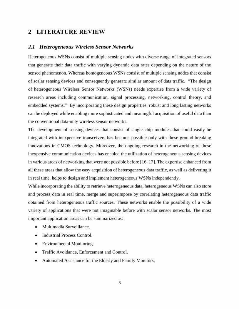
Multimedia Surveillance.
Industrial Process Control.
Environmental Monitoring.
Traffic Avoidance, Enforcement and Control.
Automated Assistance for the Elderly and Family Monitors.
9
2.2 Network Architecture
The architecture of WSNs is based on many dominating factors depending upon the nature of the
application for which WSNs are being deployed i.e. ad hoc networks, mobile networks or self-
organizing infrastructures. “The composition of WSNs is envisioned to be of heterogeneous sensor
devices having diverse capabilities in terms of processing, sensing and communication.” These
heterogeneous sensing devices can thus produce miscellaneous forms of traffic. Conventional
WSNs architecture design problems have been centred on scalable network architectures in which
each sensing node has the same sensing capabilities, which are homogenous and flat architectures.
On the other hand, a different perspective is required by the innate heterogeneity of these sensors
due to diverse technologies that sustain different traffic and dynamic sensor types.
The realization of heterogeneous network architectures led by these intrinsic differences of WSNs
are mainly classified into following two categories:
2.2.1 Single-Tier Architectures in WSNs
A single node of the deployed sensor network can have higher processing capabilities as compared
to the other sensing nodes in a single tier architecture. “These nodes which can be used for local
processing of the sensed media information are referred to as processing hubs.” Furthermore,
various processing hubs can create a distributed processing architecture, which may be used to
execute a particular processing job distributively.
The stored and processed heterogeneous data is relayed to a remote wireless gateway through a
multi-hop track made by intermediate sensing nodes in the single tier architecture. For successive
redemption, a storage hub which is responsible for storing local heterogeneous data, is
interconnected to the remote wireless gateway. Consequently, to perform more sophisticated
processing tasks offline and to mitigate the storage hindrances on the sensing nodes, the central
location can be used to store acquired and processed data easily.
For networks comprising of heterogeneous devices, the single tier architecture may be
implemented to reduce the overall load. In this scenario by organizing all the sensing nodes into
clusters, a central cluster head is responsible for controlling the diverse type of sensors in the
cluster. However, extra resource-hungry jobs, such as aggregation or intensive heterogeneous
traffic processing can be achieved by the cluster head. As a result, the cluster heads can also be
utilized as processing hubs in this type of architecture. The gathered content, is then relayed to a

10
remote wireless gateway with dedicated and enhanced processing capabilities for further
processing and storage by the cluster head in order to minimize the overall load on an individual
sensing node.
2.2.2 Multi-Tier Architectures in WSNs
The multi-tiered network hierarchical structure with heterogeneous sensing devices delivers the
adaptive scalability and flexibility to utilize the network resources more efficiently. To perform
elementary jobs, the multitier architecture incorporates low-end scalar sensors at the subsidiary
hierarchical levels. The data traffic assembled by these sensing nodes can thus be used to trigger
more complicated sensing functions, such as real-time observation of the acquired content. High-
end sensing nodes perform these important functions at leading hierarchical levels that are
equipped with high data rate traffic sensors. Moreover, storage and processing can be triggered
based on the report by low-end devices only when there is adequate temptation in the sensed
phenomenon.
Figure 2.1 Architecture of Heterogeneous WSNs

11
By boosting the efficiency and robustness of the established heterogeneous sensors, the network
lifetime is enhanced by utilizing such hierarchical architecture. Each tier may include cluster for
enhanced and dedicated processing in the multi-tier architecture. Consequently, due to
communication between these sensors, autonomous functions for each cluster can be achieved,
which reduces the energy consumption. Furthermore, the traffic load in the network may be
reduced by accumulating and transporting useful data to the higher tiers at the cluster heads.
2.3 Design Factors of Heterogeneous WSNs
There are several design challenges to the perception of heterogeneous WSNs in terms of
communication capability, digital signal processing, networking infrastructure and coverage
ranges, few of which are explained as follow:
2.3.1 Heterogeneous Traffic Source Coding
By accounting the redundancy in the heterogeneous traffic, source coding aims to reduce the
statistical content to be sent through the wired or wireless medium. This can be accomplished by
obtaining the interrelations between each pixel in the acquired data and at each frame the
correlation between pixels is calculated. “This is called intraframe compression.” Moreover, each
consecutive frame is intrinsically correlated as the large portion of that information stays consistent
between successive frames.
Consequently, by benefiting from the redundancy in the acquired data the raw data may be
compressed through advanced coding techniques [18]. The meaningful content to be transported
is certainly reduced as the result of the compression techniques. This compression usually results
in corruption of data which ultimately delivers reduced quality of the sensed information.
2.3.2 Application-Specific Quality of Services
The optimum effort service utility is normally incorporated for the networking and communication
techniques aimed for WSNs i.e. no full fledge guarantees are supplied in terms of throughput,
delay, energy consumption, and jitter. Whereas, these types of guarantees are particularly required
for efficient and robust delivery of the sensed content in case of heterogeneous traffic applications.
Moreover, QoS requirements in a network are influenced by the classification of applications. As
a result, different degrees of QoS guarantees are compulsory for the information carried by each
heterogeneous traffic stream. Furthermore, the algorithms that sustain application-specific QoS

12
demand, in terms of bounds on delay, energy consumption, distortion, reliability and network
lifetime, are imperative for the design and development of heterogeneous WSNs.
2.3.3 Increased Bandwidth Demand
The compressed data traffic still exceeds the current capabilities of wireless sensor nodes
irrespective of the fact that heterogeneous traffic coding techniques remarkably decrease the
transported content. Transmission bandwidth demanded by heterogeneous sensors is orders of
volume larger than what is delivered by currently available sensing nodes. Advanced and
sophisticated transmission techniques that deliver larger bandwidth at acceptable energy utilization
levels are of essential importance by this increased bandwidth demand. Moreover, there is the call
of development of novel hardware architectures for improved and enhanced heterogeneous traffic-
capable transceivers.
2.3.4 Heterogeneous Traffic In-Network Processing
For improved energy-efficient data logging, in-network processing has been utilized in
heterogeneous WSNs, but for this area novel approaches are imperative for dynamically various
features of the heterogeneous information. WSNs work in the similar fashion but aggregation
operations are normally incorporated using in-network processing which is a prominent difference
distinguishing simple WSNs from heterogeneous WSNs. Furthermore, executing linear operations
like additions or carrying out averages with scalar data is effortless whereas aggregation is not
simple in heterogeneous WSNs as multiple packets in a stream deliver the heterogeneous traffic
content. Consequently, the whole stream must be assembled and the heterogeneous data must be
decoded to deduce meaningful information from a stream of traffic. Enhanced storage and
processing capabilities are mandatory for this task at intermediate sensing nodes. So an
intermediate node can execute aggregation function on various traffic streams after decoding only.
Therefore in-network processing is not practical as it does not produce significant results for the
case of heterogeneous WSNs.
2.3.5 Efficient Energy Consumption
A major deal in conventional WSNs is energy utilization. Due to two basic contrasts, this factor is
even more prominent in heterogeneous WSNs. Large magnitudes of traffic is delivered by
heterogeneous traffic applications, so even prolonged transmission times are necessary for the

13
battery-constrained sensing devices. Whereas utilizing the in-network processing solutions, we
normally overcome the transmission delays in conventional WSNs, these techniques may become
incompatible for heterogeneous WSNs due to the extensive processing demands of heterogeneous
data traffic. By decreasing the energy consumption, solutions for heterogeneous WSNs may
guarantee the QoS demands for various applications.
2.3.6 WSN Resource Constraints
Each component in heterogeneous WSNs is limited in terms of processing capability, memory,
data rate and battery similar to conventional WSNs. The significance of energy-efficient operation
in heterogeneous WSNs is demonstrated by the higher processing demands as well as significantly
higher traffic volume of encoders. As a result, the efficient consumption of existing resources is
very essential for heterogeneous traffic delivery.
2.3.7 Coverage Range
The direction of data acquisitions is normally dissimilar in case of scalar sensors which results in
comparatively circular sensing ranges. Whereas directivity characterizes the coverage in
heterogeneous traffic sensors rather than absolutely omnidirectional coverage. A limited field of
view (FoV) in case of heterogeneous sensors results in substantially dissimilar conic coverage
areas as compared to omnidirectional nature of scalar sensors. Furthermore, in heterogeneous
sensor field of view (FoV) the sensing range is relatively longer than that of omnidirectional scalar
sensors. Novel approaches in design, development and topology control in heterogeneous WSNs
motivate these basic dissimilarities in terms of coverage.
2.3.8 Functional Cross-Layer Coupling
Evolving communication protocols and utilizing and considering the impacts of cross-layer in each
layer performance on every other layer is imperative. However, the cross-layer design principles
are also applicable to heterogeneous WSNs, because of the direct dependence of the application
layer on the heterogeneous traffic an additional dimension also exists. In cellular and ad hoc
networks combined source and channel coding algorithms for the transportation of wireless
heterogeneous traffic have been implemented. For energy-efficient communication an independent
cross-layer design is imperative which must be integrated with the close interaction of other
protocol layers in heterogeneous WSNs.

14
2.3.9 Variable Channel Capacity
During the last decade both wired and wireless networks have been researched for heterogeneous
traffic communication. The main concern of this research has been delivering QoS guarantees in
terms of throughput, delay and jitter. While the properties of heterogeneous WSNs create novel
design factors in this area.
2.4 WSN Coverage
The coverage of the network also impact the architecture for WSNs. The architecture should be
developed by considering the coverage issues for each of the components in the network, in order
to provide necessary coverage for a particular application. The derivation of various coverage
factors of the scalar sensor types such as humidity or temperature sensors as compared to that of
heterogeneous traffic sensors such as microphones and cameras is an imperative and concluding
challenge.
“The range that a node can reach through wireless communication is defined by the trade-off
between communication and sensing range.” As a result, the connectivity in the network is usually
limited by the coverage problem in WSNs [19]. WSNs present basically different properties on
the coverage in terms of range, directivity, line of sight and dynamic view.
2.4.1 WSN Range
Scalar sensors have the omnidirectional nature so their sensing range is generally fixed.
Furthermore, there is a close correlation between the location and the coverage area of scalar
sensors. Thus, depending on the direction of a sensor the sensing range of the sensor changes due
to the directional changes in the sensing node. As well as, sensing range of scalar sensors is usually
low as compared to the cameras which are the heterogeneous traffic sensors. The field of view
(FoV) is therefore unrelated to the location of a sensor. “The range of a sensor depends on the
application type which is another important factor in the range of coverage of these sensors.” For
example, a farther object cannot be monitored as clearly as compared to an object that is very close
to a camera, due to the insufficient resolution of the camera lens. Contrary to this factor, the range
and the coverage area of a sensor for different applications would be much broader if only the
presence of an object was essential.

15
2.4.2 WSN Directivity
The video and most importantly audio sensors obtain information based on their direction instead
of the scalar sensors which are omnidirectional inherently. The coverage area that a video sensor
can capture is defined by the field of view (FoV) in video sensors.
In case of scalar sensors, to characterize the coverage of WSN node, the sensing range and the
location of a sensor are enough whereas, in case of heterogeneous sensors, many other parameters
should also be considered like the direction and field of view (FoV), size and shape of the sensing
node. Moreover, given the various positions and orientations of the cameras compared to the
observed area or event, each heterogeneous traffic sensor acquires information from a different
and unique viewpoint from the environment.
2.4.3 WSN Line of Sight
The impact of hindrances in the environment also vary the coverage of heterogeneous WSNs. If
there is no hurdle in between, only in that case a camera sensor can record an image of an object.
Hence, there is a close relationship between the line of sight and the coverage of a sensor network.
For the coverage problems in WSNs consisting of heterogeneous sensors, this fact results in
different challenges.
2.4.4 WSN Dynamic View
The coverage of heterogeneous WSNs is constantly changing due to the zoom operation as well
as the pan and tilt capabilities of cameras these days. This delivers a challenge for their design and
development but also adds scalability and flexibility to the operation of these heterogeneous
WSNs. Depending on the conditions in the environment, the tendency to change the field of view
(FoV) results in a more comparative operation of sensors in the network. Using the pan and tilt
operation of heterogeneous sensors in order to gather sufficient data, a group of heterogeneous
sensors can be positioned to a specific location of interest. Dynamic changes are incorporated in
the coverage of the network using these local changes in the focus and the orientation of the video
sensors. Whereas, various advantages are delivered by controlling the coverage of the network, to
provide complete coverage of the in the area of interest for efficiently communicating in the
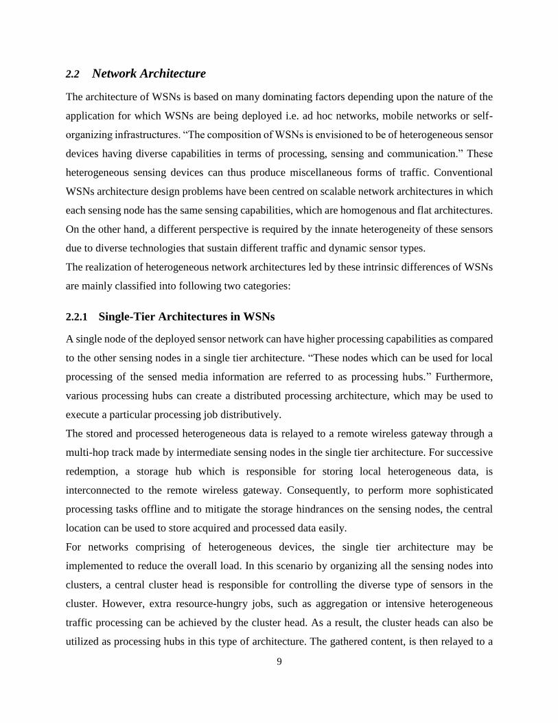
network. Thus, in heterogeneous WSNs, the location of the video sensors are usually uncorrelated
to their field of views (FoVs). Moreover, with overlapping field of views (FoVs) position of the
16
two sensors can be fixed at far end locations. As a result, through a multi-hop track, the efficient
communication of the variance in view of one of these sensing nodes should be delivered to the
other sensor.
(a) Scalar Sensors (b) Video Sensors
Figure 2.2 Depiction of the Coverage in WSNs
2.5 Heterogeneous Sensor Hardware
The capabilities of the heterogeneous sensor devices are fundamentally different in the design of
heterogeneous WSNs. A significantly diverse set of functionalities are provided by embedding the
resource-constrained wireless sensors like video and audio devices in heterogeneous WSNs.
Although, the higher processing power and bandwidth requirements of heterogeneous sensing
need to be accommodated by the components as well as the hardware architecture of the wireless
devices.
The existing hardware in the field heterogeneous sensors are classified into three categories that is
audio sensors, low-resolution video sensors and medium-resolution video sensors, all of them are
discussed in the following section:
2.5.1 Battery-less and Wireless Wearable Microphones
For health monitoring a wireless and battery-less microphone has been implemented at
Massachusetts Institute of Technology (MIT) [20]. To capture lung, respiratory, or surrounding
sounds, the microphone can be attached to any part of the human body and is in the shape of a

17
mole. To collect external and internal sounds, multiple sensors can be attached to different parts
of the body. Through magnetic induction communication between the sensors and a wearable
reader is performed. The sensor modulates an electromagnetic field, which is generated by the
transceiver in the reading, according to the observed acoustic wave by changing its capacitance.
As a result, the sensors operate battery-less and only the reader is powered using a battery. Since
no heavy batteries or wires are necessary for the sensors so this phenomenon provides flexibility
for operation on the human body.
2.5.2 Mic-on-board Sensor Board
The Panasonic WM-62A microphone is one of the most common sensor boards used in
Crossbow’s MTS300/310 and MTS510. Only a small current of 500 μA is required for its
operation. A preamplifier and a second-stage amplifier, is used in composition of the microphone
circuitry, with a digital-pot control [21]. The sounds coming from any direction can be recorded
as the microphone works in an omnidirectional manner. These audio sensors can receive sound
waves with a frequency smaller than 5 kHz.
Acoustic ranging is the most common usage of the on-board microphones. To estimate the distance
between two nodes, the difference between an acoustic signal and the propagation speed of a radio
wave is used. Audio signal transmission and speech recognition is another promising application
for audio sensors. Thus, with the low-end microphones like this one, many potential applications
are possible such as sound detection.
Figure 2.3 MTS310 Sensor Board

18
2.6 Low-Resolution Video Sensors
For the development of video cameras, charge-coupled device (CCD) technology has been used
traditionally. But recently, a new technology which is generally used for the manufacture of
computer processors, called complementary metal oxide semiconductor (CMOS) is being used for
video cameras. Image sensors can be implemented with an image processing circuit, a lens and an
image sensor on the same chip using CMOS technology. The cost and scale of image sensors is
significantly reduced using this composition. The reduction in size does not affect the quality since
complementary metal oxide semiconductor (CMOS) image quality closely follows charge-coupled
device (CCD) quality for low-resolution and medium-resolution sensors. Thus, complementary
metal oxide semiconductor (CMOS) sensors have become most suitable candidates for
heterogeneous WSNs since they consume much less energy than their charge-coupled device
(CCD) counterparts.
Table 2-1 Specifications of video sensors.
Name Resolution Processor Speed
(MHz)
Data Rate
(kbps)
Frame Rate
(fps)
Embedded
Transceiver
Cyclops 352 x 288 7.3 N/A N/A No
CMUcam3 80 x 143 75 N/A 16.7 No
CMUcam2 176 x 255 75 N/A 26 No
CMUcam3 352 x 288 60 N/A 50 No
MeshEye (Low-Resolution) 30 x 30 50 250 N/A Yes
MeshEye (High-Resolution) 352 x 288 50 250 15 Yes
Panoptes 320 x 240 206 1024 20 Yes
Acroname Garcia 640 x 480 400 250,1024 30 Yes
2.6.1 Cyclops Video Sensors
Developed for Mica2 and MicaZ nodes, Cyclops is a sister-board [22]. Cyclops is connected to a
Mica2 or MicaZ node for communication purposes just like the sensor boards.

19
Figure 2.4 Cyclops Video Sensor Mote
Cyclops includes a microcontroller unit (MCU), an image sensor, a complex programmable logic
device (CPLD), an external flash memory and an external SRAM. From the network node, the
complexity of the vision algorithms is separated by this board. TinyOS libraries are included in
the Cyclops firmware that are also compatible with the Mica-family motes. For image compression
and analysis advanced processes such as coordinate conversion and background subtraction as
well as simple manipulation capabilities as matrix operations, all are provided by these libraries.
2.6.2 CMUcam Camera Systems
CMUcam family of embedded camera systems is another platform for image sensors. CMUcam
consists of a microcontroller, a complementary metal oxide semiconductor (CMOS) camera, and
a level shifter for the RS232 interface [23]. A second microcontroller can be connected to perform
image processing tasks in parallel which is an important feature of CMUcam. For communication,
CMUcam needs to be connected to a transceiver unit. CMUcam, CMUcam2, and CMUcam3 have
been developed so far respectively.
(a) CMUcam (b) CMUcam2 (c) CMUcam3
Figure 2.5 Hierarchy of Integrated CMUcam Camera Systems

20
2.6.3 MeshEye Video Sensor
Applications may require multiple cameras on a single sensor mote, to cater such situations
MeshEye sensor motes have been developed [24]. A maximum of two CIF (352 × 288) image
sensors and four low-resolution (30 × 30) optical sensors can be accommodated by this sensing
mote. A transceiver that is compatible with the IEEE 802.15.4 standard is also embedded into the
board with a data rate of 250 kbps. Up to six cameras can be used concurrently with the expansion
interface on this sensor board. For dedicated computation and storage an external FRAM or flash
memory can also be interfaced with the sensing mote.
Figure 2.6 MeshEye Video Sensor Mote
2.7 Medium-Resolution Video Sensors
High-power solutions that are specifically designed for heterogeneous WSNs including webcams
also exist. These platforms are based boards that possess higher processing, communication and
storage capabilities than typical sensor motes. An off-the-shelf webcam can be integrated to form
a stand-alone visual sensor using enhanced processing capabilities of these devices. The usage of
these devices can be incorporated in such applications where image processing and higher
resolution are mandatory.

21
2.7.1 Panoptes Video Sensor
Panoptes is one of the first stand-alone visual sensor platforms to be implemented using mostly
off-the-shelf components [25]. Linux operating system is used the Panoptes video sensor and the
Intel StrongARM embedded platform is used as microprocessor in them. The IEEE 802.11
wireless cards are used for communication between multiple Panoptes nodes.
A USB-based video camera that can capture video of 320 × 240 resolution, is interfaced with the
Panoptes video sensor, at 18–20 fps. Many image processing and filtering tools including video
capture, JPEG and differential JPEG compression, filtering for compression, buffering, and
streaming are also equipped within the software architecture of the Panoptes.
Figure 2.7 Panoptes Video Sensor Platform
2.7.2 GARCIA A Mobile Robot Video Sensor
The GARCIA mobile, a high-end video sensor comprises of a pan–tilt camera installed on a
GARCIA robotic platform [26]. To handle sensor inputs, motion control, infrared (IR)
communication and serial interface, the GARCIA robot is equipped with two separate 40MHz
processors. Environmental awareness of the robot for automated obstacle detection, motion
control, and maneuvering is provided by these features.
To provide for communication as well as for sensing tasks a microprocessor can also be connected
to the main board of the video sensor. To connect a webcam, which constitutes a mobile video
sensor on top of it, can also be interfaced with a pan–tilt camera bloom of the GARCIA robot. The
resulting platform can be used for adaptive sampling in a heterogeneous sensor network.

22
Figure 2.8 GARCIA Mobile Robot Integrated With Pan–Tilt Camera
2.8 Examples of Deployed Multimedia Sensor Networks
Following are some recent experimental studies which are mostly limited to video sensor
networks:
2.8.1 SensEye Testbed Platform
Object detection, object recognition, and object tracking are the three tasks that are accomplished
through the SensEye application. A multi-tier architecture is followed by the SensEye network
architecture. A hierarchical structure of various heterogeneous components with various
processing and sensing capabilities is organized. While minimizing energy consumption
continuous and adaptive surveillance operation is provided by the resulting structure. SensEye
application is composed of three tiers that is why it is called a multi-tier architecture. The SensEye
testbed is an example of how heterogeneous components can be used in a WSN to provide a
surveillance application [27].
Lowest tier sensors that provide continuous sensing of the surveillance area record any activity
which is then communicated to the second tier where low-resolution video sensors perform object
recognition. Object detection and recognition is also provided by these low-resolution video
sensors in second tier. Medium-resolution webcams are located in the third tier which are
interfaced with Crossbow Stargate boards.

23
Figure 2.9 SensEye: Multi-Tier Architecture Depiction [27]
These boards are capable of communicating through the IEEE 802.11 interface with both a control
center and the lower tier components. Moreover, on this tier the interested areas can be recorded
with a higher resolution images. The hierarchical tasks of the SensEye application, improve energy
efficiency by reducing the energy consumption, by using the higher end devices and their resources
only when necessary, while still providing complete coverage for the surveillance application.
2.8.2 Meerkats Testbed Platform
To investigate the energy consumption profile of heterogeneous WSNs of medium-resolution
video sensor nodes the Meerkats testbed has been constructed [28]. Stargate boards interfaced with
Logitech webcams are used in the testbed same as in case of SensEye testbed. IEEE 802.11
wireless network cards connected to each Stargate board is used to perform communication
between nodes in the network. To measure the energy consumption for different types of
operations that are typical of a heterogeneous WSN the Meerkats testbed is used.
Communication, idle, visual sensing, storage, and processing are the five main categories which are
investigated using Meerkats testbed. A benchmark for energy consumption is build up by these
categories in WMSNs. By direct measurements of current both steady state and transient energy
consumption behaviour are obtained with the help of a digital multimeter. The figure below shows

24
the energy consumption for sleep mode as well as the five major operations. Moreover, we can
also be observe the breakdown of the energy consumption in the sensor, processor and the radio.
The conventional balance of energy consumption for processing and communication, is
contradicted by an important observation that reading from or writing to flash memory as well as
image the processing applications are more energy consuming than communication in
heterogeneous WSNs, which favors processing. Furthermore, visual sensing and communication
consumes almost same energy, which is also an important characteristic of heterogeneous WSNs.
So the additional amounts of energy consumed and delays due to transitions (e.g., to go to sleep
mode) are not negligible and must be accounted for in the network and protocol design in
heterogeneous WSNs.
Figure 2.10 Graph Depicting Average Current Consumption for Various Tasks [28]
2.8.3 IrisNet Software Platform
For deploying heterogeneous services on heterogeneous WSNs, Internet-scale Resource-Intensive
Sensor Network Services (IrisNet) is an example software platform [29]. By performing Internet-
like queries IrisNet allows a global wide area sensor network to be harnessed on this infrastructure.
To collect potentially useful data scalar sensors and video sensors are spread throughout the
25
environment. Internet-like queries to video sensors are provided to the users by IrisNet. The sensor
network can be queried by the user through a high-level language i.e. Extensible Markup Language
(XML) which allows easy organization of hierarchical data.
Two tiered architecture of IrisNet is implemented. In first tier a common shared interface called
sensing agents (SAs) is implemented by the heterogeneous sensors, while in second tier the
produced data is stored in a distributed database by the sensors that is implemented on organizing
agents (OAs). Thus, the same hardware infrastructure can provide different sensing services as
different sensing services run simultaneously on the architecture. For instance, a surveillance
service as well as a parking space finder service can be provided by a set of video sensors. To
answer the class of relevant queries a group of organizing agents (OAs) are responsible for a
sensing service, collecting the data produced by sensing service and organizing the information in
a distributed database.

26
CHAPTER 3
DESIGN CHALLENGES
27
3 DESIGN CHALLENGES
3.1 Methodology
In our project we are applying collaborative communication approach for monitoring physiological
conditions of on-field football players. Due to drastic increase in number of matches played by the
players, it is necessary for the players to keep their physical condition and fitness up-to the
requirement of the game. In order to avoid any serious physical injury during an ongoing match
their physicians and coaches should have to monitor and analyze their body parameters
continuously such as fatigue through temperature, heart rate etc., distance run during matches, and
location data to improve team strategy during matches.
A range of biomedical sensors for the continuous observation and measurement of different
physiological functions of the targeted player can be embedded for this purpose with the designed
WSN node. Biomedical Sensors which we are going to use are Pulse Sensor SEN-11574 to
measure heart rate of the football player and DS18B20 which is a 1-wire digital temperature sensor
both of them provides the real time statistics of the football player in the football field.
To establish an autonomous, efficient, effective and intelligent data management system we are
designing and implementing an ad-hoc system which may prove to be a life saver for the football
players on the field. The basic idea is to collect player’s basic physiological and location statistics.
For example heart rate, blood pressure, speed, temperature through bio-medical sensors attached
to a wearable kit and creating a sophisticated wireless sensor network (WSN) to transport this data
back to the sink/ base station node through collaborative communication for further processing.
3.1.1 Collaborative Communication
Collaborative Communication [30, 31] is an effective physical layer approach to extend the
transmission range and increase energy efficiency. According to Collaborative Communication, a
group of collaborative nodes participate to transmit or receive a common signal when they
communicate with an isolated node located far away from them. The key point in Collaborative
Communication is to modify the carrier phase of the collaborative nodes so that multiple signals
are synchronized [32]. For instance, in the transmit mode, multiple signals are received by the
isolated node synchronously and combined constructively to increase the signal quality, or
equivalently extend transmission range. Collaborative Communication is a feasible alternative to
28
control the network topology in wireless networks with resource-restricted nodes, since the
performance of Collaborative Communication mainly depends on the number of collaborative
nodes rather than on the capabilities of each individual node. In other words, increasing in the
number of collaborative nodes can somehow compensate the weak communication capabilities of
individual nodes.
3.1.2 System Diagram
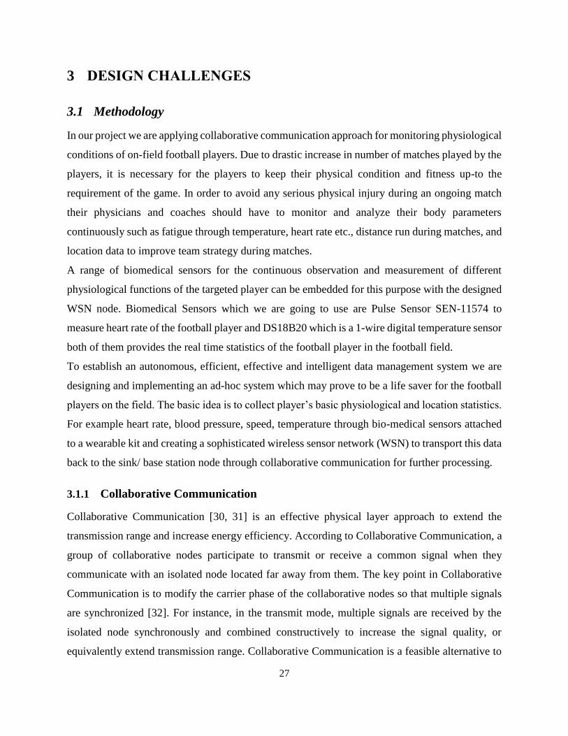
Following is the system diagram of the implemented ad hoc network in which each football player
on the field is wearing a WSN node. The acquired physiological statistics by each node are
transmitted to the sink/ base node by passing it to the nearest intermediate node which after
multiplexing both passed and acquired statistics communicates these statistics to the next
intermediate node [33]. Ultimately the overall multiplexed physiological statistics of all the players
are relayed to the sink/ base station node where these statistics can be processed to extract useful
information about the present health conditions of each football player. The team manager of the
football players can monitor the health of all the players over Android mobile app as well as
manager can have remote access to these statistics via internet from anywhere in the world. The
team manager can also email these statistics to another system with higher processing capabilities
for enhanced and dedicated analysis for the purpose of guiding management decisions, including
when to make therapeutic interventions and assessment of those interventions.
Figure 3.1 System Diagram of Implemented Ad Hoc Network

29
3.2 Hardware Components
Following are the tools which we are using in order to achieve our desired objectives:
3.2.1 Processing Unit [34]
The Arduino Mega 2560 is a microcontroller board based on the ATmega2560. It has 54 digital
input/output pins (of which 15 can be used as PWM outputs), 16 analog inputs, 4 UARTs
(hardware serial ports), a 16 MHz crystal oscillator, a USB connection, a power jack, an ICSP
header, and a reset button. It contains everything needed to support the microcontroller; simply
connect it to a computer with a USB cable or power it with an AC-to-DC adapter or battery to get
started. The Mega is compatible with most shields designed for the Arduino Duemilanove or
Diecimila.
Figure 3.2 Arduino Mega 2560 MCU Board
3.2.2 Communication Sensor [35]
XBee ZB Series 2 ZigBee modules provide cost-effective wireless connectivity to devices in
ZigBee mesh networks. Utilizing the ZigBee PRO Feature Set, these modules are interoperable
with other ZigBee devices, including devices from other vendors. Programmable versions of the
XBee-PRO ZB ZigBee module make customizing ZigBee applications easy, even without wireless
design expertise. These modules allow a very reliable and simple communication between
microcontrollers, computers, systems, really anything with a serial port! Point to point and multi-
point networks are supported.

30
Figure 3.3 Zigbee Based XBee Series 2 Module
Table 3-1 Performance Specifications of XBee Series 2 Module.
XBEE Specification Value
Indoor/ Urban Range Up to 133 ft. (40 m)
Outdoor RF Ling-of-Sight Range Up to 400 ft. (120 m)
Transmit Power Output 2mW (+ 3dBm)
RF Data Rate 25,000 bps
Data Throughput Up to 35000 bps
Serial Interface Data Rate 1200 bps – 1 Mbps
Receiver Sensitivity -96 dBm
Supply Voltage 2.1 – 3.6 Volts
Operating Frequency Band ISM 2.4 Ghz
Operating Temperature -40 to 85° C
3.2.3 Location Sensor [36]
The SkyNav SKM53 Series with embedded GPS antenna enables high performance navigation in
the most stringent applications and solid fix even in harsh GPS visibility environments. It is based
on the high performance features of the MediaTek 3329 single-chip architecture, its –165dBm
tracking sensitivity extends positioning coverage into place like urban canyons and dense foliage
environment where the GPS was not possible before. The 6-pin UART connector design is the
easiest and convenient solution to be embedded in a portable device and receiver like PND, GPS
mouse, car holder, personal locator, speed camera detector and vehicle locator.

31
Figure 3.4 SKM53 GPS Module
3.2.4 Pulse Sensor [37]
The Pulse Sensor Amped is a plug-and-play heart-rate sensor for Arduino which can easily
incorporate live heart-rate data for monitoring purpose.It essentially combines a simple optical
heart rate sensor with amplification and noise cancellation circuitry making it fast and easy to get
reliable pulse readings. Also, it sips power with just 4mA current draw at 5V so it’s great for
mobile applications. One can simply clip the Pulse Sensor to one's earlobe or fingertip and plug it
into a 3 or 5 Volt Arduino and the heart rate can be readily observed using a Processing sketch for
visualizing heart rate data. The 24" cable on the Pulse Sensor is terminated with standard male
headers so there’s no soldering required. The dimensions of the Pulse Sensor is 0.625" (inches) in
diameter with only 0.125" (inches) thickness.
Figure 3.5 SEN-11574 - Pulse Sensor
3.2.5 Digital Temperature Sensor [38]
The DS18B20 digital thermometer provides 9-bit to 12-bit Celsius temperature measurements and
has an alarm function with non-volatile user programmable upper and lower trigger points. The
DS18B20 communicates over a 1-Wire bus that by definition requires only one data line (and
ground) for communication with a central microprocessor. It has an operating temperature range

32
of -55°C to +125°C and is accurate to ±0.5°C over the range of -10°C to +85°C. In addition, the
DS18B20 can derive power directly from the data line (“parasite power”), eliminating the need for
an external power supply. Each DS18B20 has a unique 64-bit serial code, which allows multiple
DS18B20s to function on the same 1-Wire bus. Thus, it is simple to use one microprocessor to
control many DS18B20s distributed over a large area. Applications that can benefit from this
feature include HVAC environmental controls, temperature monitoring systems inside buildings,
equipment, or machinery, and process monitoring and control systems.
Figure 3.6 DS18B20 - A 1-Wire Digital Temperature Sensor
3.3 Software Architecture
3.3.1 Hardware/ Software Configuration and Integration
After identification our ultimate goal to interface various biomedical sensors for continuous
observation and measurement of the football player’s physiological function. We intended to
design a sophisticated ad hoc network for the purpose of guiding management decisions, including
when to make therapeutic interventions and assessment of those interventions through
collaborative communication.
In order to do so first of all we accomplished serial communication of the three Arduino Mega
2560 based nodes in AT mode using XBee ZB series 2 modules to connect all the three of them in
a network. Arduino software (IDE) 1.0.6 is being used for writing and uploading code into the
Arduino MCU and X-CTU software by Digi International is being used to program and configure
the XBEE with Arduino microcontroller and different sensors. After serial communication we
incorporated wireless communication of these nodes in AT mode. Following the wireless AT mode
communication capable of wireless collaborative communication and logging potentially useful

33
statistical data into the server for both online and an Android mobile app based access, we moved
towards interfacing of various biomedical and location tracking sensor.
We interfaced SEN-11574 Pulse Sensor to measure the heart rate and for location tracking we
interfaced SKM53 GPS module to acquire GPS coordinates through satellite for tracking the
movements of different football players on the field with all the configured WSN nodes. A
Microsoft SQL Server based database has also been created to store the physiological parameters
and the GPS coordinates of the football players.
3.3.2 XBEE Configuration
We are using X-CTU by Digi International, which is a free multi-platform application designed to
enable developers to interact with Digi RF modules through a simple-to-use graphical interface.
Figure 3.7 X-CTU Software

34
It includes new tools that make it easy to set-up, configure and test XBee® RF modules. XCTU
includes all of the tools a developer needs to quickly get up and running with XBee. Unique
features like graphical network view, which graphically represents the XBee network along with
the signal strength of each connection, and the XBee API frame builder, which intuitively helps to
build and interpret API frames for XBees being used in API mode, combine to make development
on the XBee platform easier than ever.
3.3.3 Android Mobile App
We have developed a user friendly Android based mobile app which includes the profiles of each
player depicting trace graph of players, total meters run during match, a range of physiological
parameters and other customizable operations for guiding management decisions that can prove
very helpful for the real time as well as offline observation of both previously and currently
acquired statistics for both health and performance assessment of the football players. Based on
the acquired statistics of the respective player we can tell when to take precautionary measures in
order to avoid any health issues and ultimately the death of the player.
3.3.4 App Development Procedure
Following are the steps involved in the development of user friendly Android mobile app interface:
1. First of all Splash Screen is designed in which App name, background pictures and time
duration of splash screen display are embedded.
(a) Mobile App Splash Screen (b) Mobile App Login Window

35
2. After that Sign up page is designed in which editable text fields for email, password for
coach login, brief introduction and photograph of coach are provided.
(c) Coach Sign Up Window (d) Coach Photo (e) Coach Profile
3. After that player profiles are made in which bio data and other necessary information like
player position and playing style of each individual player in the football team is entered.
(f) Player Registering (g) Player 1 Profile (h) Player 2 Profile
4. After registering all the players, when the coach of the football team logins using his email
and password following information relating to coach and players is shown in the App:

36
(i) Coach Sign In (j) Coach Profile (k) List of Player
5. Player mobility map to track location of the football player on the field is incorporated
using the GPS coordinates which is portrayed using the Google Maps.
(l) Player Mobility Map 1 (m) Player Mobility Map 2 (n) Player Mobility Map 3
Figure 3.8 Mobile App User Interface

37
3.3.5 Microsoft SQL Server Database
SQL Server Management Studio (SSMS) is an integrated environment for accessing, configuring,
managing, administering, and developing all components of SQL Server. SSMS combines a broad
group of graphical tools with a number of rich script editors to provide access to SQL Server to
developers and administrators of all skill levels.
SSMS combines the features of Enterprise Manager, Query Analyzer, and Analysis Manager,
included in previous releases of SQL Server, into a single environment. In addition, SSMS works
with all components of SQL Server such as Reporting Services and Integration Services.
Developers get a familiar experience, and database administrators get a single comprehensive
utility that combines easy-to-use graphical tools with rich scripting capabilities.
A Microsoft SQL Server based database has also been created to store the physiological and
location parameters using various biomedical sensors and GPS sensor for location tracking through
GPS coordinates of the football players. As WSN nodes acquire physiological parameters of the football
players periodically and transmit these statistics to the coordinator set up at the database station which
serially uploads acquired health and location parameters over the database. The coordinator node takes
about 5 seconds to transmit these parameters over the database for the first time after that physiological
parameters are updated after 1 every second in the database.
Figure 3.9 Microsoft SQL Server Management Studio

38
CHAPTER 4
TESTING AND RESULTS

39
4 TESTING AND RESULTS
4.1 Wearable Hardware Design
The final integrated WSN node is wearable only over specific body positions like upper area of arm, chest
and back of the football player. The size and dimension of the final deliverable is sustainable enough to
deliver accurate and useful results so that critical conditions of the players can be identified and therapeutic
interventions can be successfully performed. The battery consumption of the WSN node is within
acceptable range to deliver power for long enough time so that physiological statistics of the football players
can be easily acquired for one match and proper analysis of health parameters of players can be performed
easily. Also overall life time of the WSN node is also enhanced due to low battery consumption. Uniross
NI-MH 9 volts battery with 200mAh has been used to power each WSN node which delivers power to these
nodes for more than 1.5 hours. Each WSN node consumes around 133.33mA of battery and the power
consumed per bit is obtained to be around 125µ watts which is sustainable enough to deliver satisfactory
results.
4.2 Communication Aspects
As WSN nodes acquire physiological parameters of the football players periodically and transmit these
statistics to the coordinator set up at the database station which serially uploads acquired health and location
parameters over the database. The coordinator node takes about 5 seconds to transmit these parameters over
the database for the first time after that physiological parameters are updated after 1 every second in the
database. The router which is a wearable node by the football player transmits around 200 bits per second
on average which are in raw form. Out of these 200 raw bits on average 160 useful bits per second are
received by the coordinator at the sink/ base station which after processing serially uploads these acquired
parameters over the Microsoft SQL based database for both online and Android mobile app based access.
4.2.1 Line of Sight Communication (LOS)
Under normal conditions the transmission time during line of sight (LOS) communication is 13 seconds on
average between router and coordinator whereas between two routers the average transmission time is 20
seconds and average time to transmit acquired data of both routers collaboratively to the sink/ base node is
33 seconds. Furthermore, when one router is out of range of coordinator to directly transmit its data to the
sink/ base station, the average transmission time is 13 seconds between router and coordinator. Similarly
average transmission time between two routers is 13 seconds and as a result average time to transmit
acquired data of both routers collaboratively to the sink/ base node is 26 seconds.
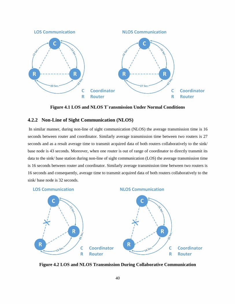
40
Figure 4.1 LOS and NLOS T`ransmission Under Normal Conditions
4.2.2 Non-Line of Sight Communication (NLOS)
In similar manner, during non-line of sight communication (NLOS) the average transmission time is 16
seconds between router and coordinator. Similarly average transmission time between two routers is 27
seconds and as a result average time to transmit acquired data of both routers collaboratively to the sink/
base node is 43 seconds. Moreover, when one router is out of range of coordinator to directly transmit its
data to the sink/ base station during non-line of sight communication (LOS) the average transmission time
is 16 seconds between router and coordinator. Similarly average transmission time between two routers is
16 seconds and consequently, average time to transmit acquired data of both routers collaboratively to the
sink/ base node is 32 seconds.
Figure 4.2 LOS and NLOS Transmission During Collaborative Communication

41
4.3 Integrated Hardware/ Software Design
The integrated WSN node is a hardware/ software integrated system and its wearable form has dimensions
of 4x4 inches. The final integrated hardware and software based system that is capable of measuring
important statistics of football players for health monitoring.
4.3.1 Final Deliverable
WSN based nodes have been designed for continuous observation and measurement of the player’s
physiological function by assessing the acquired statistics for the purpose of guiding management
decisions, including when to make therapeutic interventions and assessment of those interventions.
The designed and implemented idea of an ad-hoc system would be proved to be a life saver for the
football players on the field.
The final deliverable is a hardware and software based integrated system that is capable of
measuring important statistics of football players for health monitoring. The designed system has
a long communication range (120m outdoor), low power requirements (2mW), high data rate (up
to 250kbps) and more processing capability (16 MHz crystal oscillator achieves throughputs
approaching 1 MIPS per MHz) to achieve said objectives. Due to the harsh environment like
football field the orientation of sensors, design and on body placement of our final integrated
system is sustainable enough to deliver accurate and potential results and wearable node does not
interferes with the player activities during the game. The team manager is able to access the
acquired statistics from anywhere and can also email and process these statistics on any other
system for enhanced and dedicated analysis of these statistics.
4.3.2 Features
The designed and implemented ad hoc network is a solution to serious health issues for monitoring
critical health conditions of patients. The acquired statistics of the football players can also be used
for the comparison of their performance on the field. These statistics can help in detailed grading
process to gauge how players execute their roles over the course of a game. The implemented
system delivers the ease of access to the team manager for assessing statistics for guiding
management decisions from anywhere. Efficient energy communication methods are employed in
the implemented system through the usage of collaborative communication. It is a cost effective
method for health monitoring of the football players. The designed ad hoc network is scalable and

42
flexible in nature with the aim for future expansion, in which the WSN nodes have increased life
cycle due to the inherent capability of low power consumption.
Figure 4.3 Wearable WSN Kit

43
CHAPTER 5
CONCLUSIONS AND FUTURE WORK

44
5 CONCLUSIONS AND FUTURE WORK
5.1 Conclusions
Our primary goal was to interface a range of biomedical sensors for continuous observation and
measurement of the targeted player’s physiological function for assessing the acquired statistics
for the purpose of guiding management decisions, including when to make therapeutic
interventions and assessment of those interventions. Furthermore, we can use the acquired
statistics of the football players for the comparison of their performance on the field. These
statistics can be used to help identify players who are demonstrating sustained form and
consistently delivering over a number of weeks rather than just a big haul in one game.
These statistics can also help for the goal of detailed grading process to gauge how players execute
their roles over the course of a game by looking at the performance of each individual on each
play. By looking beyond the box score and studying the statistics to grade how well each player
performs on each play, and as a result over the course of a game and a season. How well a lineman
blocks on a given play, how much space and help a runner receives, how effectively a pass rusher
brings pressure or how well a defender covers a receiver. A lot of extra statistics such as yards
after catch, yards after contact, missed tackles, dropped passes, etc. can also be collected for
grading individual performance on each play.
The designed and implemented ad hoc network is a solution to serious health issues for monitoring
critical health conditions of patients. Efficient energy communication methods are employed in
the implemented system through the usage of collaborative communication due to which network
life cycle is increased. Also the designed ad hoc network is scalable and flexible in nature with the
aim for future expansion. By assessing the acquired statistics by the WSN wearable kit for the
purpose of guiding management decisions, including when to make therapeutic interventions and
assessment of those interventions, the designed and implemented ad-hoc system shall prove to be
a life saver for the football player’s on the field.

45
Figure 5.1 Pie Chart Depicting Battery Consumed by Various Tasks in WSN Node
5.2 Future Work
After achieving these goals a range of other biomedical sensors can also be interfaced with the
WSN nodes like oximetry sensor and spirometer etc. that would enable us to monitor these other
real time physiological statistics of the football players as well for guiding management decisions.
Later on, we can apply “Data Compression techniques” to reduce the number of bits to be sent
over the network and increase the life-time of the network by applying suitable methods like
coding, modelling, and transforming. By doing this we would have to select a particular type of
compression technique which can either be loss-less or lossy that would vary as per our required
scenario [39].
Furthermore, we can develop a renewable source of energy through “Energy Harvesting”
techniques [40] for the designed WSN node. Without energy, a sensor is essentially useless and
cannot contribute to the utility of the network as a whole. Sensor nodes need to exploit the sporadic
availability of energy to quickly sense and transmit the data. The life of WSN node is determined
33%
27%
36%
4%
Battery Consumption
Cost of Processing
Cost of Communication
Cost of Location Tracking
Cost of Sensors

46
by the capacity of its power source and power consumption of the node. By using this approach
we can not only equip our WSN node with unlimited source of energy but also we can increase
the life of the WSN node.
We can further implement our current designed system over Bluetooth Low Energy (BLE) which
is a wireless communications system aimed at novel applications in the healthcare, fitness,
security, and home entertainment industries [41]. Bluetooth Low Energy (BLE) is intended to
replace the cables connecting many types of devices, from mobile phones and headsets to hear
monitors and medical equipment. Bluetooth Low Energy (BLE) or Bluetooth Smart can provide
considerably reduced power consumption and cost while maintaining a similar communication
range as conventional Bluetooth wireless technology. In revamped WSN nodes all the wires
connecting many types of devices with each other will be replaced with wireless connectivity and
ultimately improved and renovated product will be delivered with better capabilities. The resulting
system will be more feasible in terms of miniaturization, on body placement, commercial
application point of view and power consumption, managing which is a major a major issue in
case of WSNs.
REFERENCES
[1] I. F. Akyildiz and M. C. Vuran, Wireless Sensor Networks, 1st ed. Chichester, United
Kingdom: Wiley, 2010, ch. 1, 2 and 15 sec. 1.1, 2.2-2.5 and 15.1-15.3, pp. 1, 17-33 and
350-357.
[2] IEEE 802.15.4 Standard.
[3] J. M. Rabaey et al., “PicoRadio Supports Ad Hoc Ultra-Low Power Wireless Networking,”
in IEEE Journal: Computer, Los Alamitos, CA, 2000, pp. 42-48.
[4] E. M. Petriu et al., “Sensor-Based Information Applications,” in IEEE Instrumentation &
Measurement Magazine, Vol. 3 No.4, 2000, pp. 31-35.
[5] Boomerang Shooter Detection System. Available: http://bbn.com/boomerang.
[6] Dust Networks Inc. Available: http://www.dust-inc.com.
[7] I. F. Akyildiz et al., “Wireless sensor Networks: A Survey,” in Computer Networks: The
International Journal of Computer and Telecommunications Networking, New York, NY,
2002, pp. 393-422.

47
[8] Center for Coastal Margin Observation and Prediction. Available:
http://www.ccalmr.ogi.edu/corie.
[9] D. J. Cook and S. K. Das, “Wireless Sensor Networks”, in Smart Environments:
Technology, Protocols and Applications, 1st ed. Hoboken, NJ: Wiley, 2004, ch. 2.
[10] I. F. Akyildiz et al., “Next Generation/Dynamic Spectrum Access/Cognitive Radio
Wireless Networks: A Survey,” in Computer Networks: The International Journal of
Computer and Telecommunications Networking, New York, NY, 2006, pp. 2127-2159.
[11] E. A. Basha, et al., “Model-Based Monitoring for Early Warning Flood Detection,” in
Proc. of 6th ACM Conf. on Embedded Network Sensor Systems, New York, NY, 2008, pp.
295-308.
[12] Y. Kim et al., “NAWMS: Nonintrusive Autonomous Water Monitoring System,” in Proc.
of 6th ACM Conf. on Embedded Network Sensor Systems, New York, NY, 2008, pp. 309-
322.
[13] J. M. Kahn et al., “Next Century Challenges: Mobile Networking for Smart Dust,” in Proc.
of 5th Annu. ACM/IEEE International Conf. on Mobile Computing and Networking, New
York, NY, 1999, pp. 271-278.
[14] Artificial Retina Project. Available: http://artificialretina.energy.gov.
[15] D. Malan et al., “CodeBlue: An Ad Hoc Sensor Network Infrastructure for Emergency
Medical Care,” in Proceedings of Workshop on Applications of Mobile Embedded Systems
(WAMES 2004), Boston, MA, USA, June 2004.
[16] I. F. Akyildiz et al., “A Survey on Wireless Multimedia Sensor Networks,” in Computer
Networks 51, Vol. 4, March 2007, pp. 921-960.
[17] S. Misra et al., “A Survey of Multimedia Streaming in Wireless Sensor Networks” in IEEE
Communications Surveys & Tutorial 10, Vol. 4, 2008, pp. 18-39.
[18] B. Girod et al., “Distributed Video Coding” in Proceedings of the IEEE 93, Vol. 1, January
2005, pp. 71-83.
[19] Y. Charfi et al., “Visual Sensor Networks: Opportunities and Challenges” in Information
and Communication Technologies International Symposium (ICTIS’07), Sydney,
Australia, April 2007.
[20] K. J. Cho and H. H. Asada, “Wireless, Battery-Less Stethoscope for Wearable Health
Monitoring” in Proceedings of the IEEE Northeast Bioengineering Conference,
Philadelphia, PA, USA, April 2002, pp. 187-188.
[21] MTS/MDA Sensor Board Users Manual.

48
[22] M. Rahimi et al., “Cyclops: in Situ Image Sensing and Interpretation in Wireless Sensor
Networks” in Proceedings of the ACM Conference on Embedded Networked Sensor
Systems (SenSys), San Diego, CA, USA, November 2005.
[23] A. Rowe et al., “A Low Cost Embedded Color Vision System” in Proceedings of the
IEEE/RSJ International Conference on Intelligent Robots and Systems (IROS), Lausanne,
Switzerland, October 2002.
[24] I. Downes et al., “Development of a Mote for Wireless Image Sensor Networks” in
Proceedings of COGnitive Systems with Interactive Sensors (COGIS’06), Paris, France,
March 2006.
[25] X. Fafoutis et al., “Energy Harvesting – Wireless Sensor Networks for Indoors
Applications Using IEEE 802.11,” in Procedia Computer Science: The 5th Int. Conf. on
Ambient Systems, Networks and Technologies, Aalborg, Denmark, 2014, pp. 991-996.
[26] Acroname GARCIA robotic platform. http://www.acroname.com/garcia/garcia.html.
[27] P. Kulkarni et al., “SensEye: A Multi-tier Camera Sensor Network” in Proceedings of ACM
Multimedia, Singapore, November 2005.
[28] C. B. Margi et al., “Characterizing Energy Consumption in a Visual Sensor Network
Testbed” in Proceedings of the IEEE/Create-Net International Conference on Testbeds
and Research Infrastructures for the Development of Networks and Communities
(TridentCom’06), Barcelona, Spain, March 2006.
[29] S. Nath et al., “A Distributed Filtering Architecture for Multimedia Sensors” in
Proceedings of BaseNets’04, San Jose, CA, USA, October 2004.
[30] R. Mudumbai et al., “Distributed Transmit Beamforming Using Feedback Control,” in
IEEE Transactions on Information Theory, Piscataway, NJ, 2010, pp. 411-426.
[31] B. Banitalebi et al., “On the Feasibility of Receive Collaboration in Wireless Sensor
Networks,” in IEEE 21st Int. Symp. on Personal, Indoor and Mobile Radio
Communications, Istanbul, Turkey, 2010, pp. 1608-1613.
[32] R. Mudumbai et al., “Distributed Transmit Beamforming: Challenges and Recent
Progress,” in IEEE Communication Magazine, Piscataway, NJ, 2009, pp. 102-110.
[33] Sensor Technology, 1st ed., Elsevier, Burlington, MA, 2005, pp. 575-589.
[34] Arduino. Available: http://www.arduino.cc/.
[35] Digi International. Available: http://www.digi.com/.
[36] GPS Module to the Arduino. Available: http://playground.arduino.cc/Tutorials/GPS.
[37] Pulse Sensor SEN-11574. Available: https://www.sparkfun.com/products/11574.

49
[38] DS18B20 1-Wire Digital Temperature Sensor. Available:
https://www.sparkfun.com/products/245.
[39] T. Srisooksai et al., “Practical Data Compression in Wireless Sensor Networks: A Survey,”
in Journal of Network and Computer Applications, London, United Kingdom, 2012, pp.
37-59.
[40] W. C. Feng et al., “Panoptes: Scalable Low-power Video Sensor Networking
Technologies” in Proceedings of the 11th ACM International Conference on Multimedia,
Berkeley, CA, USA, November 2003, pp. 562-571.
[41] Bluetooth Low Energy. Available: http://www.bluetooth.com/Pages/low-energy-tech-
info.aspx.

50
Appendix A: C Source Code
The source codes are also available in the CD provided with the dissertation.
Transmitter (Router) Code:
/*
---------------------- Notes ---------------------- ----------------------
This code:
1) Blinks an LED to User's Live Heartbeat PIN 13
2) Fades an LED to User's Live HeartBeat
3) Determines BPM
4) Prints All of the Above to Serial
5) attached purple wire with A0 analog pin
*/
// Variables
#include <SoftwareSerial.h>
#include <TinyGPS.h>
/* This sample code demonstrates the normal use of a TinyGPS object.
It requires the use of SoftwareSerial, and assumes that you have a
4800-baud serial GPS device hooked up on pins 11 (rx) and 10 tx).
*/
TinyGPS gps;
char msg =' ';
const int led =13;
SoftwareSerial ss(10, 11);
static void smartdelay(unsigned long ms);
static void print_float(float val, float invalid, int len, int prec);
static void print_int(unsigned long val, unsigned long invalid, int len);
static void print_date(TinyGPS &gps);
static void print_str(const char *str, int len);
int BPMS=0;
#include <OneWire.h>
#include <DallasTemperature.h>
// Data wire is plugged into pin 7 on the Arduino
#define ONE_WIRE_BUS 9
// Setup a oneWire instance to communicate with any OneWire devices (not just Maxim/Dallas temperature
ICs)
OneWire oneWire(ONE_WIRE_BUS);
// Pass our oneWire reference to Dallas Temperature.
DallasTemperature sensors(&oneWire);
int pulsePin = 9; // Pulse Sensor purple wire connected to analog pin 9
int blinkPin = 13; // pin to blink led at each beat
int fadePin = 5; // pin to do fancy classy fading blink at each beat
int fadeRate = 0; // used to fade LED on with PWM on fadePin
// Volatile Variables, used in the interrupt service routine!
volatile int BPM; // int that holds raw Analog in 0. updated every 2mS
volatile int Signal; // holds the incoming raw data
volatile int IBI = 600; // int that holds the time interval between beats! Must be seeded!
51
volatile boolean Pulse = false; // "True" when User's live heartbeat is detected. "False" when not a "live
beat".
volatile boolean QS = false; // becomes true when Arduoino finds a beat.
// Regards Serial OutPut -- Set This Up to your needs
static boolean serialVisual = true; // Set to 'false' by Default. Re-set to 'true' to see Arduino Serial Monitor
ASCII Visual Pulse
void setup(){
sensors.begin();
pinMode(blinkPin,OUTPUT); // pin that will blink to your heartbeat!
pinMode(fadePin,OUTPUT); // pin that will fade to your heartbeat!
Serial.begin(9600); // we agree to talk fast!
interruptSetup(); // sets up to read Pulse Sensor signal every 2mS
// UN-COMMENT THE NEXT LINE IF YOU ARE POWERING The Pulse Sensor AT LOW
VOLTAGE,
// AND APPLY THAT VOLTAGE TO THE A-REF PIN
// analogReference(EXTERNAL);
Serial.print("Testing TinyGPS library v. "); Serial.println(TinyGPS::library_version());
Serial.println("by Dr.Ali Nawaz Khan And their Fyp Students in 2015");
Serial.println();
Serial.println("---- ---- Latitude Longitude ");
Serial.println(" (deg) (deg) ");
Serial.println("-------------------------------------------------------------------------------------------------------------
------------------------");
pinMode(led,OUTPUT);
ss.begin(9600);
}
// Where the Magic Happens
void loop(){
float flat, flon;
//unsigned long age, date, time, chars = 0;
// unsigned short sentences = 0, failed = 0;
gps.f_get_position(&flat, &flon);
serialOutput() ;
if (QS == true){ // A Heartbeat Was Found
// BPM and IBI have been Determined
// Quantified Self "QS" true when arduino finds a heartbeat
digitalWrite(blinkPin,HIGH); // Blink LED, we got a beat.
fadeRate = 255; // Makes the LED Fade Effect Happen
// Set 'fadeRate' Variable to 255 to fade LED with pulse
BPMS= serialOutputWhenBeatHappens(); // A Beat Happened, Output that to serial.
QS = false; // reset the Quantified Self flag for next time
}
else {
digitalWrite(blinkPin,LOW); // There is not beat, turn off pin 13 LED
}
ledFadeToBeat(); // Makes the LED Fade Effect Happen
sensors.requestTemperatures(); // Send the command to get temperatures
//Serial.println("DONE");
//Serial.print("Temperature for Device 1 is: ");
float n=sensors.getTempCByIndex(0);

52
//Serial.println(n);
//smartdelay(1000);
//delay(1000);
Serial.print("2");Serial.print(";");print_float(flat, TinyGPS::GPS_INVALID_F_ANGLE, 10,
6);Serial.print(";");print_float(flon, TinyGPS::GPS_INVALID_F_ANGLE, 11,
6);Serial.print(";");Serial.print(BPMS); Serial.print(";");Serial.print(n);Serial.print(";");
while(Serial.available() > 0) {
msg=Serial.readString();
if(msg[0]=='2') {
digitalWrite(led,HIGH);
Serial.println(msg);
delay(1000);
//delay(1000);
// delay(1000);
}
if(msg[0]=='1') {
digitalWrite(led,HIGH);
Serial.println(msg);
delay(1000);
delay(1000);
//delay (1000); // take a break
}
static void smartdelay(unsigned long ms)
{
unsigned long start = millis();
do
{
while (ss.available())
gps.encode(ss.read());
} while (millis() - start < ms);
}
static void print_float(float val, float invalid, int len, int prec)
{
if (val == invalid)
{
while (len-- > 1)
Serial.print('*');
Serial.print(' ');
}
else
{
Serial.print(val, prec);
int vi = abs((int)val);
int flen = prec + (val < 0.0 ? 2 : 1); // . and -
flen += vi >= 1000 ? 4 : vi >= 100 ? 3 : vi >= 10 ? 2 : 1;
for (int i=flen; i<len; ++i)
Serial.print(' ');
}
smartdelay(0);
}
static void print_int(unsigned long val, unsigned long invalid, int len)

53
{
char sz[32];
if (val == invalid)
strcpy(sz, "*******");
else
sprintf(sz, "%ld", val);
sz[len] = 0;
for (int i=strlen(sz); i<len; ++i)
sz[i] = ' ';
if (len > 0)
sz[len-1] = ' ';
Serial.print(sz);
smartdelay(0);
}
Receiver (Coordinator) Code:
String msg = " ";
String msg2 = " ";
//char abc='';//contains the message from arduino sender
const int led = 13; //led at pin 13
void setup() {
Serial.begin(9600);//Remember that the baud must be the same on both arduinos
pinMode(led,OUTPUT);
}
void loop() {
while(Serial.available() > 0) {
msg=Serial.readString();
if(msg[0]=='2') {
digitalWrite(led,HIGH);
Serial.println(msg);
delay(1000);
//delay(1000);
// delay(1000);
}
if(msg[0]=='1') {
digitalWrite(led,HIGH);
Serial.println(msg);
delay(1000);
//delay(1000);
// delay(1000);
}
}
}
Android Mobile App Codes:
Coach:
package com.example.shanu.myapp;
import android.content.Intent;
import android.support.v7.app.ActionBarActivity;

54
import android.os.Bundle;
import android.view.Menu;
import android.view.MenuItem;
import android.view.View;
import android.widget.Button;
import android.widget.TextView;
import com.parse.ParseFile;
import com.parse.ParseImageView;
import com.parse.ParseUser;
public class Coach extends ActionBarActivity {
Button team;
TextView name,intro;
ParseImageView imgDp;
@Override
protected void onCreate(Bundle savedInstanceState) {
super.onCreate(savedInstanceState);
setContentView(R.layout.activity_coach);
name=(TextView) findViewById(R.id.name);
intro=(TextView) findViewById(R.id.intro);
imgDp=(ParseImageView) findViewById(R.id.parseImage);
ParseFile file=ParseUser.getCurrentUser().getParseFile("image");
imgDp.setParseFile(file);
imgDp.loadInBackground();
name.setText(ParseUser.getCurrentUser().getString("name"));
intro.setText(ParseUser.getCurrentUser().getString("introduction"));
team=(Button) findViewById(R.id.team);
team.setOnClickListener(new View.OnClickListener() {
@Override
public void onClick(View v) {
Intent Team = new Intent(Coach.this,Team.class );
startActivity(Team);
}
});
}
@Override
public boolean onCreateOptionsMenu(Menu menu) {
// Inflate the menu; this adds items to the action bar if it is present.
getMenuInflater().inflate(R.menu.menu_coach, menu);
return true;
}

55
@Override
public boolean onOptionsItemSelected(MenuItem item) {
// Handle action bar item clicks here. The action bar will
// automatically handle clicks on the Home/Up button, so long
// as you specify a parent activity in AndroidManifest.xml.
int id = item.getItemId();
//noinspection SimplifiableIfStatement
if (id == R.id.logout) {
ParseUser.getCurrentUser().logOut();
startActivity(new Intent(this,Login.class));
this.finish();
return true;
}
return super.onOptionsItemSelected(item);
}
}
CustomAdaptor:
package com.example.shanu.myapp;
import android.app.Activity;
import android.content.Context;
import android.content.res.Resources;
import android.view.LayoutInflater;
import android.view.View;
import android.view.ViewGroup;
import android.widget.BaseAdapter;
import android.widget.LinearLayout;
import android.widget.TextView;
import java.util.ArrayList;
/**
* Created by Shanu on 4/5/2015.
*/
public class CustomAdaptor extends BaseAdapter
{
ArrayList<String> data = new ArrayList<String>();
private static LayoutInflater inflater=null;
Activity activity;
public Resources res;
public CustomAdaptor(Activity a, ArrayList<String> d, Resources reslocal){
activity = a;
data=d;
res = reslocal;
inflater = ( LayoutInflater )activity.

56
getSystemService(Context.LAYOUT_INFLATER_SERVICE);
}
public static class ViewHolder{
public TextView name;
// public LinearLayout button;
}
@Override
public int getCount() {
return data.size();
}
@Override
public Object getItem(int position) {
return position;
}
@Override
public long getItemId(int position) {
return position;
}
@Override
public View getView(int position, View convertView, ViewGroup parent) {
View vi=convertView;
ViewHolder holder;
if(vi==null){
vi=inflater.inflate(R.layout.player_name,parent,false);
holder=new ViewHolder();
holder.name =(TextView) vi.findViewById(R.id.playerName);
// holder.button =(LinearLayout) vi.findViewById(R.id.Buttons);
vi.setTag(holder);
}else{
holder=(ViewHolder) vi.getTag();
}
holder.name.setText(data.get(position));
return vi;
}
}
EnterTeam:
package com.example.shanu.myapp;
import android.app.Dialog;
import android.content.Intent;

57
import android.support.v7.app.ActionBarActivity;
import android.os.Bundle;
import android.view.Menu;
import android.view.MenuItem;
import android.view.View;
import android.widget.Button;
import android.widget.TextView;
import android.widget.Toast;
import com.parse.ParseUser;
public class EnterTeam extends ActionBarActivity {
int countMembers=0;
Button newPlayer;
String team="";
@Override
protected void onCreate(Bundle savedInstanceState) {
super.onCreate(savedInstanceState);
setContentView(R.layout.activity_enter_team);
String names=ParseUser.getCurrentUser().getString("team");
if(names!=null){
String[] namesArray=names.split(";");
countMembers=namesArray.length;
}
newPlayer=(Button) findViewById(R.id.newPlayer);
newPlayer.setText("Enter Player " + (countMembers + 1));
newPlayer.setOnClickListener(new View.OnClickListener() {
@Override
public void onClick(View v) {
if (countMembers < 12) {
dialog();
} else {
Toast.makeText(getApplicationContext(), "Total 11 player added",
Toast.LENGTH_SHORT).show();
}
}
});
if(ParseUser.getCurrentUser().getString("team")!=null){
team= ParseUser.getCurrentUser().getString("team");
}else{
team= "";
}
}
private void dialog() {
final Dialog enterPlayer=new Dialog(this);
enterPlayer.setContentView(R.layout.new_player_entry);
final TextView playerName=(TextView) enterPlayer.findViewById(R.id.dialogName);
final TextView playerAge=(TextView) enterPlayer.findViewById(R.id.dialogAge);

58
final TextView playerPosition=(TextView) enterPlayer.findViewById(R.id.dialogPosition);
Button submit=(Button) enterPlayer.findViewById(R.id.dialogButton);
submit.setOnClickListener(new View.OnClickListener() {
@Override
public void onClick(View v) {
String name=playerName.getText().toString();
String age=playerAge.getText().toString();
String position=playerPosition.getText().toString();
if(dataEntered(name,age,position)){
team=team+name+","+age+","+position+";";
countMembers++;
newPlayer.setText("Enter Player " + (countMembers + 1));
ParseUser.getCurrentUser().put("team",team);
ParseUser.getCurrentUser().saveEventually();
enterPlayer.dismiss();
}
}
});
enterPlayer.show();
}
private boolean dataEntered(String name, String age, String position) {
boolean ret=true;
if(name.isEmpty()){
ret=false;
Toast.makeText(getApplicationContext(),"Enter Player's
Name",Toast.LENGTH_SHORT).show();
}else if(!name.contains(" ")){
ret=false;
Toast.makeText(getApplicationContext(),"Enter Player's Full
Name",Toast.LENGTH_SHORT).show();
}else if(age.isEmpty()){
ret=false;
Toast.makeText(getApplicationContext(),"Enter Player's Age",Toast.LENGTH_SHORT).show();
}else if(position.isEmpty()){
ret=false;
Toast.makeText(getApplicationContext(),"Enter Player's
Position",Toast.LENGTH_SHORT).show();
}
return ret;
}
@Override
public boolean onCreateOptionsMenu(Menu menu) {
// Inflate the menu; this adds items to the action bar if it is present.
getMenuInflater().inflate(R.menu.menu_enter_team, menu);
return true;
}
59
@Override
public boolean onOptionsItemSelected(MenuItem item) {
// Handle action bar item clicks here. The action bar will
// automatically handle clicks on the Home/Up button, so long
// as you specify a parent activity in AndroidManifest.xml.
int id = item.getItemId();
//noinspection SimplifiableIfStatement
if (id == R.id.action_skip) {
startActivity(new Intent(this,Coach.class));
this.finish();
return true;
}
return super.onOptionsItemSelected(item);
}
}
Login:
package com.example.shanu.myapp;
import android.content.Intent;
import android.support.v7.app.ActionBarActivity;
import android.os.Bundle;
import android.view.Menu;
import android.view.MenuItem;
import android.view.View;
import android.widget.Button;
import android.widget.EditText;
import android.widget.Toast;
import com.parse.LogInCallback;
import com.parse.Parse;
import com.parse.ParseException;
import com.parse.ParseUser;
public class Login extends ActionBarActivity {
Button submit;
Button signup;
EditText user,pass;
@Override
protected void onCreate(Bundle savedInstanceState) {
super.onCreate(savedInstanceState);
setContentView(R.layout.activity_login);
user=(EditText) findViewById(R.id.username);
pass=(EditText) findViewById(R.id.password);

60
signup=(Button) findViewById(R.id.signup);
submit=(Button) findViewById(R.id.submit);
submit.setOnClickListener(new View.OnClickListener() {
@Override
public void onClick(View v) {
if(dataCheck(user.getText().toString(),pass.getText().toString() )) {
ParseUser.logInInBackground(user.getText().toString(), pass.getText().toString(), new
LogInCallback() {
@Override
public void done(ParseUser parseUser, ParseException e) {
if (e==null){
startActivity(new Intent(Login.this,Coach.class));
Login.this.finish();
}else{
Toast.makeText(getApplicationContext(),"Incorrect Username or
Password",Toast.LENGTH_SHORT).show();
}
}
});
}
}
});
signup.setOnClickListener(new View.OnClickListener() {
@Override
public void onClick(View v) {
startActivity(new Intent(Login.this,Signup.class));
}
});
}
@Override
public boolean onCreateOptionsMenu(Menu menu) {
// Inflate the menu; this adds items to the action bar if it is present.
getMenuInflater().inflate(R.menu.menu_login, menu);
return true;
}
@Override
public boolean onOptionsItemSelected(MenuItem item) {
// Handle action bar item clicks here. The action bar will
// automatically handle clicks on the Home/Up button, so long
// as you specify a parent activity in AndroidManifest.xml.
int id = item.getItemId();
//noinspection SimplifiableIfStatement
if (id == R.id.action_settings) {
return true;
61
}
return super.onOptionsItemSelected(item);
}
private boolean dataCheck(String user, String pass){
boolean ret = true;
if (user.isEmpty()){
ret = false;
}
else if (pass.isEmpty()){
ret = false;
}
return ret;
}
}
MainActivity:
package com.example.shanu.myapp;
import android.content.Intent;
import android.support.v7.app.ActionBarActivity;
import android.os.Bundle;
import android.view.Menu;
import android.view.MenuItem;
import com.parse.ParseUser;
public class MainActivity extends ActionBarActivity {
@Override
protected void onCreate(Bundle savedInstanceState) {
super.onCreate(savedInstanceState);
setContentView(R.layout.activity_main);
Thread timer = new Thread(){
public void run(){
try {
sleep(3000);
} catch (InterruptedException e) {
e.printStackTrace();
}finally {
if(ParseUser.getCurrentUser()==null) {
Intent main = new Intent(MainActivity.this, Login.class);
startActivity(main);
}else{
Intent main = new Intent(MainActivity.this, Coach.class);
startActivity(main);
62
}
}
}
};
timer.start();
}
@Override
protected void onPause() {
super.onPause();
this.finish();
}
@Override
public boolean onCreateOptionsMenu(Menu menu) {
// Inflate the menu; this adds items to the action bar if it is present.
getMenuInflater().inflate(R.menu.menu_main, menu);
return true;
}
@Override
public boolean onOptionsItemSelected(MenuItem item) {
// Handle action bar item clicks here. The action bar will
// automatically handle clicks on the Home/Up button, so long
// as you specify a parent activity in AndroidManifest.xml.
int id = item.getItemId();
//noinspection SimplifiableIfStatement
if (id == R.id.action_settings) {
return true;
}
return super.onOptionsItemSelected(item);
}
}
PlayerMovement:
package com.example.shanu.myapp;
import android.graphics.Point;
import android.os.Handler;
import android.os.SystemClock;
import android.support.v4.app.FragmentActivity;
import android.os.Bundle;
import android.view.animation.Interpolator;
import android.view.animation.LinearInterpolator;
import com.google.android.gms.maps.CameraUpdate;

63
import com.google.android.gms.maps.CameraUpdateFactory;
import com.google.android.gms.maps.GoogleMap;
import com.google.android.gms.maps.Projection;
import com.google.android.gms.maps.SupportMapFragment;
import com.google.android.gms.maps.model.LatLng;
import com.google.android.gms.maps.model.Marker;
import com.google.android.gms.maps.model.MarkerOptions;
public class PlayerMovement extends FragmentActivity {
private GoogleMap mMap; // Might be null if Google Play services APK is not available.
@Override
protected void onCreate(Bundle savedInstanceState) {
super.onCreate(savedInstanceState);
setContentView(R.layout.activity_player_movement);
setUpMapIfNeeded();
}
@Override
protected void onResume() {
super.onResume();
setUpMapIfNeeded();
}
/**
* Sets up the map if it is possible to do so (i.e., the Google Play services APK is correctly
* installed) and the map has not already been instantiated.. This will ensure that we only ever
* call {@link #setUpMap()} once when {@link #mMap} is not null.
* <p/>
* If it isn't installed {@link SupportMapFragment} (and
* {@link com.google.android.gms.maps.MapView MapView}) will show a prompt for the user to
* install/update the Google Play services APK on their device.
* <p/>
* A user can return to this FragmentActivity after following the prompt and correctly
* installing/updating/enabling the Google Play services. Since the FragmentActivity may not
* have been completely destroyed during this process (it is likely that it would only be
* stopped or paused), {@link #onCreate(Bundle)} may not be called again so we should call this
* method in {@link #onResume()} to guarantee that it will be called.
*/
private void setUpMapIfNeeded() {
// Do a null check to confirm that we have not already instantiated the map.
if (mMap == null) {
// Try to obtain the map from the SupportMapFragment.
mMap = ((SupportMapFragment) getSupportFragmentManager().findFragmentById(R.id.map))
.getMap();
// Check if we were successful in obtaining the map.
if (mMap != null) {
setUpMap();
}
}

64
}
/**
* This is where we can add markers or lines, add listeners or move the camera. In this case, we
* just add a marker near Africa.
* <p/>
* This should only be called once and when we are sure that {@link #mMap} is not null.
*/
private void setUpMap() {
double lat=31.3997258;
double lon=74.2089438;
final Marker marker = mMap.addMarker(new MarkerOptions().position(new LatLng(lat,
lon)).title("Player"));
final double finalLat = lat+0.00079;
final double finalLon = lon+0.00089;
mMap.animateCamera(CameraUpdateFactory.newLatLngZoom(new LatLng(lat, lon), 17), new
GoogleMap.CancelableCallback() {
@Override
public void onFinish() {
animateMarker(marker, new LatLng(finalLat, finalLon), false);
// animateMarker(marker, new LatLng(finalLat-0.00079, finalLon+0.00089), false);
}
@Override
public void onCancel() {
}
});
// for(int i=0;i<20;i++) {
// final double finalLat = lat;
// final double finalLon = lon;
// Thread timer = new Thread(){
// public void run(){
// try {
// sleep(3000);
// } catch (InterruptedException e) {
// e.printStackTrace();
// }finally {
//// mMap.clear();
//// mMap.addMarker(new MarkerOptions().position(new LatLng(finalLat,
finalLon)).title("Player"));
// }
// }
// };
// timer.start();
// }
}
public void animateMarker(final Marker marker, final LatLng toPosition,
final boolean hideMarker) {
final Handler handler = new Handler();

65
final long start = SystemClock.uptimeMillis();
Projection proj = mMap.getProjection();
Point startPoint = proj.toScreenLocation(marker.getPosition());
final LatLng startLatLng = proj.fromScreenLocation(startPoint);
final long duration = 10000;
final Interpolator interpolator = new LinearInterpolator();
handler.post(new Runnable() {
@Override
public void run() {
long elapsed = SystemClock.uptimeMillis() - start;
float t = interpolator.getInterpolation((float) elapsed
/ duration);
double lng = t * toPosition.longitude + (1 - t)
* startLatLng.longitude;
double lat = t * toPosition.latitude + (1 - t)
* startLatLng.latitude;
marker.setPosition(new LatLng(lat, lng));
if (t < 1.0) {
// Post again 16ms later.
handler.postDelayed(this, 16);
} else {
if (hideMarker) {
marker.setVisible(false);
} else {
marker.setVisible(true);
}
}
}
});
}
}
PlayerProfileData:
package com.example.shanu.myapp;
/**
* Created by Farhan Ahmed on 5/24/2015.
*/
public class PlayerProfileData {
private String name;
private String age;
private String position;
PlayerProfileData(String name,String age,String position){
setName(name);
setAge(age);
setPosition(position);

66
}
public String getName() {
return name;
}
public void setName(String name) {
this.name = name;
}
public String getAge() {
return age;
}
public void setAge(String age) {
this.age = age;
}
public String getPosition() {
return position;
}
public void setPosition(String position) {
this.position = position;
}
}
Signup:
package com.example.shanu.myapp;
import android.app.AlertDialog;
import android.content.DialogInterface;
import android.content.Intent;
import android.database.Cursor;
import android.graphics.Bitmap;
import android.graphics.BitmapFactory;
import android.net.Uri;
import android.provider.MediaStore;
import android.support.v7.app.ActionBarActivity;
import android.os.Bundle;
import android.view.Menu;
import android.view.MenuItem;
import android.view.View;
import android.widget.Button;
import android.widget.EditText;
import android.widget.ImageView;
import android.widget.Toast;
import com.parse.ParseException;
import com.parse.ParseFile;

67
import com.parse.ParseUser;
import com.parse.ProgressCallback;
import com.parse.SignUpCallback;
import java.io.ByteArrayOutputStream;
import java.io.File;
public class Signup extends ActionBarActivity {
ImageView img;
EditText name, intro,email,password;
Button enterTeam;
Bitmap bm=null;
String fromCam="";
@Override
protected void onCreate(Bundle savedInstanceState) {
super.onCreate(savedInstanceState);
setContentView(R.layout.activity_signup);
img=(ImageView) findViewById(R.id.signupImage);
email=(EditText) findViewById(R.id.email);
password=(EditText) findViewById(R.id.newPassword);
name=(EditText) findViewById(R.id.signupName);
intro=(EditText) findViewById(R.id.signupIntro);
enterTeam=(Button) findViewById(R.id.Signup);
img.setOnClickListener(new View.OnClickListener() {
@Override
public void onClick(View v) {
// in onCreate or any event where your want the user to
// select a file
final CharSequence[] items = { "Take Photo", "Choose from Library",
"Cancel" };
AlertDialog.Builder builder = new AlertDialog.Builder(Signup.this);
builder.setTitle("Add Photo!");
builder.setItems(items, new DialogInterface.OnClickListener() {
@Override
public void onClick(DialogInterface dialog, int item) {
if (items[item].equals("Take Photo")) {
Intent intent = new Intent(MediaStore.ACTION_IMAGE_CAPTURE);
File f = new File(android.os.Environment
.getExternalStorageDirectory(), "temp.jpg");
fromCam=f.getAbsolutePath();
intent.putExtra(MediaStore.EXTRA_OUTPUT, Uri.fromFile(f));
startActivityForResult(intent, 0);
} else if (items[item].equals("Choose from Library")) {
Intent intent = new Intent(
Intent.ACTION_PICK,
android.provider.MediaStore.Images.Media.EXTERNAL_CONTENT_URI);

68
intent.setType("image/*");
startActivityForResult(
Intent.createChooser(intent, "Select File"),1);
} else if (items[item].equals("Cancel")) {
dialog.dismiss();
}
}
});
builder.show();
}
});
enterTeam.setOnClickListener(new View.OnClickListener() {
@Override
public void onClick(View v) {
if(dataEntered()){
final ParseUser user=new ParseUser();
user.setEmail(email.getText().toString());
user.setPassword(password.getText().toString());
user.setUsername(email.getText().toString());
user.put("name", name.getText().toString());
user.put("introduction", intro.getText().toString());
if(bm!=null){
ByteArrayOutputStream stream = new ByteArrayOutputStream();
bm.compress(Bitmap.CompressFormat.JPEG, 100, stream);
byte[] byteArray = stream.toByteArray();
final ParseFile file=new ParseFile("dp.jpeg",byteArray);
try {
file.save();
} catch (ParseException e) {
e.printStackTrace();
}
user.put("image", file);
}
user.signUpInBackground(new SignUpCallback() {
@Override
public void done(ParseException e) {
if (e == null) {
Intent enterT = new Intent(Signup.this, EnterTeam.class);
// enterT.putExtra("name",name.getText().toString());
// enterT.putExtra("intro",intro.getText().toString());
// enterT.putExtra("imgPath",intro.getText().toString());
startActivity(enterT);
Signup.this.finish();
} else {
e.printStackTrace();
Toast.makeText(getApplicationContext(), "Something went wrong. Cannot Signup",
Toast.LENGTH_SHORT).show();
}
}

69
});
}
}
});
}
private boolean dataEntered() {
boolean ret=true;
String nam=name.getText().toString();
String em=email.getText().toString();
String pass=password.getText().toString();
String into=intro.getText().toString();
if(nam.isEmpty()){
Toast.makeText(getApplicationContext(),"Kindly Enter your
name",Toast.LENGTH_SHORT).show();
ret=false;
}else if(into.isEmpty()){
Toast.makeText(getApplicationContext(),"Kindly Enter your
introduction",Toast.LENGTH_SHORT).show();
ret=false;
}else if(!nam.contains(" ")){
Toast.makeText(getApplicationContext(),"Kindly Enter your full
name",Toast.LENGTH_SHORT).show();
ret=false;
}else if(em.isEmpty()){
Toast.makeText(getApplicationContext(),"Kindly Enter your
Email",Toast.LENGTH_SHORT).show();
ret=false;
}else if(pass.isEmpty()){
Toast.makeText(getApplicationContext(),"Kindly Enter your
Password",Toast.LENGTH_SHORT).show();
ret=false;
}else if(!em.contains("@")){
Toast.makeText(getApplicationContext(),"Email is incorrect",Toast.LENGTH_SHORT).show();
ret=false;
}else if(pass.length()<6){
Toast.makeText(getApplicationContext(),"Password too short. Must have 6
letters",Toast.LENGTH_SHORT).show();
ret=false;
}
return ret;
}
@Override
public boolean onCreateOptionsMenu(Menu menu) {
// Inflate the menu; this adds items to the action bar if it is present.
getMenuInflater().inflate(R.menu.menu_signup, menu);
return true;
}

70
@Override
public boolean onOptionsItemSelected(MenuItem item) {
// Handle action bar item clicks here. The action bar will
// automatically handle clicks on the Home/Up button, so long
// as you specify a parent activity in AndroidManifest.xml.
int id = item.getItemId();
//noinspection SimplifiableIfStatement
if (id == R.id.action_settings) {
return true;
}
return super.onOptionsItemSelected(item);
}
@Override
protected void onActivityResult(int requestCode, int resultCode, Intent data) {
if (resultCode == RESULT_OK) {
if(requestCode==0){
// Bundle extras = data.getExtras();
// Uri selectedImageUri = data.getData();
String tempPath = fromCam;
//get orientation here
// selectedImagePath=tempPath;
BitmapFactory.Options btmapOptions = new BitmapFactory.Options();
btmapOptions.inSampleSize=4;
// bm=(Bitmap) extras.get("data");
bm = BitmapFactory.decodeFile(tempPath, btmapOptions);
img.setImageBitmap(bm);
} else if (requestCode == 1) {
Uri selectedImageUri = data.getData();
String tempPath = getPath(selectedImageUri);
//get orientation here
// selectedImagePath=tempPath;
BitmapFactory.Options btmapOptions = new BitmapFactory.Options();
btmapOptions.inSampleSize=4;
bm = BitmapFactory.decodeFile(tempPath, btmapOptions);
img.setImageBitmap(bm);
}
}
}
/**
* helper to retrieve the path of an image URI
*/
public String getPath(Uri uri) {
// just some safety built in
if( uri == null ) {

71
// TODO perform some logging or show user feedback
return null;
}
// try to retrieve the image from the media store first
// this will only work for images selected from gallery
String[] projection = { MediaStore.Images.Media.DATA };
Cursor cursor = managedQuery(uri, projection, null, null, null);
if( cursor != null ){
int column_index = cursor
.getColumnIndexOrThrow(MediaStore.Images.Media.DATA);
cursor.moveToFirst();
return cursor.getString(column_index);
}
// this is our fallback here
return uri.getPath();
}
}
Team:
package com.example.shanu.myapp;
import android.app.Dialog;
import android.content.Intent;
import android.graphics.Color;
import android.graphics.drawable.ColorDrawable;
import android.os.Handler;
import android.support.v7.app.ActionBarActivity;
import android.os.Bundle;
import android.util.TypedValue;
import android.view.Menu;
import android.view.MenuItem;
import android.view.View;
import android.view.animation.Animation;
import android.view.animation.AnimationUtils;
import android.widget.AdapterView;
import android.widget.Button;
import android.widget.TextView;
import android.widget.Toast;
import com.parse.ParseUser;
import java.util.ArrayList;
import com.example.shanu.myapp.helper.SwipeMenu;
import com.example.shanu.myapp.helper.SwipeMenuCreator;
import com.example.shanu.myapp.helper.SwipeMenuItem;
import com.example.shanu.myapp.helper.SwipeMenuListView;
public class Team extends ActionBarActivity {

72
String[] teamRefined;
@Override
protected void onCreate(Bundle savedInstanceState) {
super.onCreate(savedInstanceState);
setContentView(R.layout.activity_team);
String teamGannd= ParseUser.getCurrentUser().getString("team");
teamRefined=teamGannd.split(";");
ArrayList<String> arrayList=new ArrayList<>();
for (int i=0;i<teamRefined.length;i++){
arrayList.add(teamRefined[i].split(",")[0]);
}
for (int j=teamRefined.length+1;j<=11;j++){
arrayList.add("Player "+j);
}
// arrayList.add("Abdul Mannan");
// arrayList.add("Abdul Qadir");
// arrayList.add("Usman Riaz");
// arrayList.add("Shan e Fazal");
// arrayList.add("Player 5");
// arrayList.add("Player 6");
// arrayList.add("Player 7");
// arrayList.add("Player 8");
// arrayList.add("Player 9");
// arrayList.add("Player 10");
// arrayList.add("Player 11");
CustomAdaptor adaptor=new CustomAdaptor(this,arrayList,getResources());
final SwipeMenuListView listView=(SwipeMenuListView) findViewById(R.id.listyn);
listView.setAdapter(adaptor);
// step 1. create a MenuCreator
SwipeMenuCreator creator = new SwipeMenuCreator() {
@Override
public void create(SwipeMenu menu) {
// create "open" item
SwipeMenuItem openItem = new SwipeMenuItem(
getApplicationContext());
// create "delete" item
SwipeMenuItem deleteItem = new SwipeMenuItem(
getApplicationContext());
// set item background

73
deleteItem.setBackground(new ColorDrawable(Color.parseColor("#ececec")));
// set item width
deleteItem.setWidth(dp2px(90));
// set a icon
deleteItem.setIcon(R.drawable.ic_action_action_account_box);
// add to menu
menu.addMenuItem(deleteItem);
// set item background
openItem.setBackground(new ColorDrawable(Color.parseColor("#444333")));
// set item width
openItem.setWidth(dp2px(90));
// set item title
openItem.setIcon(R.drawable.ic_action_device_dvr);
// set item title fontsize
openItem.setTitleSize(18);
// set item title font color
openItem.setTitleColor(Color.WHITE);
// add to menu
menu.addMenuItem(openItem);
}
private int dp2px(int dp) {
// TODO Auto-generated method stub
return (int) TypedValue.applyDimension(TypedValue.COMPLEX_UNIT_DIP, dp,
getResources().getDisplayMetrics());
}
};
// set creator
listView.setMenuCreator(creator);
// step 2. listener item click event
listView.setOnMenuItemClickListener(new SwipeMenuListView.OnMenuItemClickListener() {
@Override
public boolean onMenuItemClick(final int position, SwipeMenu menu,int index) {
switch (index) {
case 0:
Animation anim = AnimationUtils.loadAnimation(
Team.this, R.anim.slide_out_left);
anim.setDuration(800);
listView.getChildAt(position).startAnimation(anim);
new Handler().postDelayed(new Runnable() {
public void run() {
// dialog edit Player
dialogPlayer(position);

74
}
}, anim.getDuration());
break;
case 1:
// open
startActivity(new Intent(Team.this,PlayerMovement.class));
break;
}
return false;
}
});
// set SwipeListener
listView.setOnSwipeListener(new SwipeMenuListView.OnSwipeListener() {
@Override
public void onSwipeStart(int position) {
// swipe start
}
@Override
public void onSwipeEnd(int position) {
// swipe end
}
});
// other setting
// listView.setCloseInterpolator(new BounceInterpolator());
// test item long click
listView.setOnItemLongClickListener(new AdapterView.OnItemLongClickListener() {
@Override
public boolean onItemLongClick(AdapterView<?> parent, View view,
int position, long id) {
Toast.makeText(getApplicationContext(),
position + " Chadd dee", Toast.LENGTH_LONG).show();
return false;
}
});
}
private void dialogPlayer(final int pos) {
final Dialog enterPlayer=new Dialog(this);
enterPlayer.setContentView(R.layout.new_player_entry);
final TextView playerName=(TextView) enterPlayer.findViewById(R.id.dialogName);
final TextView playerAge=(TextView) enterPlayer.findViewById(R.id.dialogAge);

75
final TextView playerPosition=(TextView) enterPlayer.findViewById(R.id.dialogPosition);
Button submit=(Button) enterPlayer.findViewById(R.id.dialogButton);
Button cancel=(Button) enterPlayer.findViewById(R.id.cancel);
cancel.setVisibility(View.VISIBLE);
cancel.setOnClickListener(new View.OnClickListener() {
@Override
public void onClick(View v) {
enterPlayer.dismiss();
}
});
String[] player=teamRefined[pos].split(",");
String name=player[0];
String age=player[1];
String position=player[2];
playerName.setText(name);
playerAge.setText(age);
playerPosition.setText(position);
submit.setOnClickListener(new View.OnClickListener() {
@Override
public void onClick(View v) {
teamRefined[pos]=playerName.getText().toString()+","+playerAge.getText().toString()+","+playerPositi
on.getText().toString();
enterPlayer.dismiss();
}
});
enterPlayer.show();
}
@Override
public boolean onCreateOptionsMenu(Menu menu) {
// Inflate the menu; this adds items to the action bar if it is present.
getMenuInflater().inflate(R.menu.menu_team, menu);
return true;
}
@Override
public boolean onOptionsItemSelected(MenuItem item) {
// Handle action bar item clicks here. The action bar will
// automatically handle clicks on the Home/Up button, so long
// as you specify a parent activity in AndroidManifest.xml.
int id = item.getItemId();
//noinspection SimplifiableIfStatement

76
if (id == R.id.action_newPlayer) {
startActivity(new Intent(this,EnterTeam.class));
this.finish();
return true;
}
return super.onOptionsItemSelected(item);
}
@Override
protected void onStop() {
String team="";
for (int a=0;a<teamRefined.length;a++){
team=team+teamRefined[a]+";";
}
ParseUser.getCurrentUser().put("team",team);
ParseUser.getCurrentUser().saveEventually();
super.onStop();
}
}
Microsoft SQL Server Codes:
SQL Code:
//SQL SERVER Code.
USE [dbTest]
GO
/****** Object: Table [dbo].[tblTrackingInfo] Script Date: 4/16/2015 11:08:39 PM ******/
SET ANSI_NULLS ON
GO
SET QUOTED_IDENTIFIER ON
GO
CREATE TABLE [dbo].[tblTrackingInfo](
[intCode] [int] IDENTITY(1,1) NOT NULL,
[fltLat] [float] NULL,
[fltLang] [float] NULL,
[fltTemp] [float] NULL,
[fltHeart] [float] NULL,
[fltExtra1] [float] NULL,
[fltExtra2] [float] NULL,
[fltExtra3] [float] NULL,
[fltExtra4] [float] NULL,
[strExtra1] [nvarchar](250) NULL,
[strExtra2] [nvarchar](250) NULL,
[strExtra3] [nvarchar](250) NULL,

77
[strExtra4] [nvarchar](250) NULL,
[strExtra5] [nvarchar](250) NULL,
[dtmCreated] [datetime] NULL,
CONSTRAINT [PK_tblTrackingInfo] PRIMARY KEY CLUSTERED
(
[intCode] ASC
)WITH (PAD_INDEX = OFF, STATISTICS_NORECOMPUTE = OFF, IGNORE_DUP_KEY = OFF,
ALLOW_ROW_LOCKS = ON, ALLOW_PAGE_LOCKS = ON) ON [PRIMARY]
) ON [PRIMARY]
GO
C Sharp Code:
// SQL SERVER CODE
using System;
using System.Collections.Generic;
using System.ComponentModel;
using System.Data;
using System.Drawing;
using System.Linq;
using System.Text;
using System.Windows.Forms;
using System;
using System.Collections.Generic;
using System.IO.Ports;
using System.Configuration;
using System.Threading;
using System.Data.SqlClient;
namespace ArdineoTesting
{
public partial class Form1 : Form
{
SerialPort currentPort;
bool portFound;
String RxString = String.Empty;
static string connetionString = "Data Source=AQCHAUHAN-VAIO;Initial Catalog=dbTracking;User
ID=sa;Password=sedese";
SqlConnection con = new SqlConnection(connetionString);
Int32 intCounter = 0;
public Form1()
{
InitializeComponent();
}

78
public void fnSaveValues(Double fltLat,Double fltLng,Double fltTemp,Double fltHeart,Double
fltExtra1,Double fltExtra2,Double fltExtra3,Double fltExtra4,String strExtra1,String strExtra2,String
strExtra3,String strExtra4,String strExtra5,DateTime dtmCreated)
{
SqlCommand cmd = new SqlCommand("ProcInfo_Insert", con);
cmd.CommandType = CommandType.StoredProcedure;
cmd.Parameters.Add("@fltLat", SqlDbType.Float).Value = fltLat;
cmd.Parameters.Add("@fltLang", SqlDbType.Float).Value = fltLng;
cmd.Parameters.Add("@fltTemp", SqlDbType.Float).Value = fltTemp;
cmd.Parameters.Add("@fltHeart", SqlDbType.Float).Value = fltHeart;
cmd.Parameters.Add("@fltExtra1", SqlDbType.Float).Value = fltExtra1;
cmd.Parameters.Add("@fltExtra2", SqlDbType.Float).Value = fltExtra2;
cmd.Parameters.Add("@fltExtra3", SqlDbType.Float).Value = fltExtra3;
cmd.Parameters.Add("@fltExtra4", SqlDbType.Float).Value = fltExtra4;
cmd.Parameters.Add("@strExtra1", SqlDbType.NVarChar).Value = strExtra1;
cmd.Parameters.Add("@strExtra2", SqlDbType.NVarChar).Value = strExtra2;
cmd.Parameters.Add("@strExtra3", SqlDbType.NVarChar).Value = strExtra3;
cmd.Parameters.Add("@strExtra4", SqlDbType.NVarChar).Value = strExtra4;
cmd.Parameters.Add("@strExtra5", SqlDbType.NVarChar).Value = strExtra5;
cmd.Parameters.Add("@dtmCreated", SqlDbType.DateTime).Value = dtmCreated;
con.Open();
cmd.ExecuteNonQuery();
con.Close();
}
private void buttonStart_Click(object sender, EventArgs e)
{
arduinoBoard.PortName = txtCom.Text;
arduinoBoard.BaudRate = 9600;
arduinoBoard.Open();
if (arduinoBoard.IsOpen)
{
buttonStart.Enabled = false;
buttonStop.Enabled = true;
textBox1.ReadOnly = false;
}
//SerialPort port = new SerialPort("COM3", 9600);
//port.Open();
//while (true)
//{
// String s = Console.ReadLine();
// if (s.Equals("exit"))
// {
// break;
// }

79
// port.Write(s + '\n');
//}
//port.Close();
//SetComPort();
//DetectArduino();
}
private void arduinoBoard_DataReceived(object sender, SerialDataReceivedEventArgs e)
{
String str = arduinoBoard.ReadLine();
string[] dataArray = str.Split(';');
if (dataArray.Length > 4)
{
RxString = dataArray[0] + ";" + dataArray[1] + ";" + dataArray[2] + ";" + dataArray[3] + ";" +
dataArray[4] + ";" + Environment.NewLine;
this.Invoke(new EventHandler(DisplayText));
if (dataArray.Length <= 5)
{
intCounter++;
if (intCounter % 2 == 0)
{
fnSaveValues(Convert.ToDouble(lat), Convert.ToDouble(lng),
Convert.ToDouble(dataArray[4]), Convert.ToDouble(dataArray[3]), 0.1, 0.1, 0.1, 0.1,
Convert.ToString(dataArray[0]), "Test", "Test", "Test", "Test", DateTime.Now);
}
}
//RxString = arduinoBoard.ReadExisting();
}
}
private void DisplayText(object sender, EventArgs e)
{
textBox1.AppendText(RxString);
}
private void SetComPort()
{
try
{

80
string[] ports = SerialPort.GetPortNames();
foreach (string port in ports)
{
currentPort = new SerialPort(port, 9600);
if (DetectArduino())
{
portFound = true;
break;
}
else
{
portFound = false;
}
}
}
catch (Exception e)
{
}
}
private bool DetectArduino()
{
try
{
//The below setting are for the Hello handshake
byte[] buffer = new byte[5];
buffer[0] = Convert.ToByte(16);
buffer[1] = Convert.ToByte(128);
buffer[2] = Convert.ToByte(0);
buffer[3] = Convert.ToByte(0);
buffer[4] = Convert.ToByte(4);
int intReturnASCII = 0;
char charReturnValue = (Char)intReturnASCII;
currentPort.Open();
currentPort.Write(buffer, 0, 5);
Thread.Sleep(1000);
int count = currentPort.BytesToRead;
string returnMessage = "";
String str =Convert.ToString(currentPort.ReadByte());
while (count > 0)
{
intReturnASCII = currentPort.ReadByte();
returnMessage = returnMessage + Convert.ToChar(intReturnASCII);
count--;
}
//ComPort.name = returnMessage;
currentPort.Close();
if (returnMessage.Contains("HELLO FROM ARDUINO"))
{
return true;
}
else

81
{
return false;
}
}
catch (Exception e)
{
return false;
}
}
private void textBox1_TextChanged(object sender, System.EventArgs e)
{
}
private void buttonStop_Click(object sender, System.EventArgs e)
{
}
}
}

82
Appendix B: Hardware Schematics

83
Appendix C: List of Components
Arduino Mega 2560 MCU.
XBee ZB Series 2 Module.
Libelium: The Xbee shield.
SKM53 GPS Module.
SEN-11574 Pulse Sensor.
DS18B20 1-Wire® Digital
NI-MH 9V Battery (200 mAh).

84
Appendix D: Project Timeline
DATE June 29, 2015
PROJECT ID 05 TOTAL NUMBER
OF WEEKS IN
PLAN 40
TITLE WSN Nodes for Health Monitoring of Players on Football Field Through
Collaborative Communication
No. STARTING
WEEK DESCRIPTION OF MILESTONE DURATION
1 September Proposal Submission and FYP-I Presentation 2 Weeks
2 October Literature Review 5 Weeks
3 November Analyzing and Identifying Tools and Objectives 5 Weeks
4 December Hardware/ Software Design 6 Weeks
5 January AT Mode Serial and Wireless Communication 3 Weeks
6 February Database and Mobile App Implementation 7 Weeks
7 March Hardware/ Software Integration 4 Weeks
8 April Testing and Maturing the Ultimate Application 2 Weeks
9 May Dissertation Documentation and Submission 4 Weeks
10 June Final Deliverable Submission 2 Weeks