written by jered flickinger - future retro
TRANSCRIPT

Written by Jered Flickinger
Copyright 2017
Future Retro
www.future-retro.com

TABLE OF CONTENTS
Page 1 - Overview
Page 2 – Inputs and Outputs
Page 3 – Controls
Page 4 – Modulation Sources
Page 5 – Parameters
Instrument Select
Voice 1
Voice 2
Page 6 – Mod 1
Page 7 – Mod 2
Page 8 – Modulation Oscillator 1
Page 9 – Modulation Oscillator 2
Page 10 – Mix
Digital Effects
Page 11 – Filter
Dynamics
Save Instrument
Page 12 – Troubleshooting
Initializing the unit
Page 13 – Warranty
Specifications

OVERVIEW
The Transient is a single voice percussion module. It can recreate traditional drum voices, or dive into new
experimental territory. At times the Transient can sound like an entire drum machine or loop is playing,
morphing from rhythm to rhythm, or sound like a synthesizer when retriggering it's sounds at audio rates, or
creating other special effects. One things for sure, it's not quite like anything else we've seen before, and it has
got a sound all its own.
The foundation of sound in the Transient is more than 400 audio samples. While internal processing of these
sounds is all 16 bit resolution, a 12 bit DAC is used to add a vintage sonic character.
A unique architecture in the Transient allows these digital samples to have similar sound characteristics to
what you would expect from analog drum machines or synthesizers, and natural sounds. Natural sounds never
repeat in exactly the same way, and the Transient achieves similar results by altering the phase and amplitude
of samples.
Percussion instruments typically have a very limited, if any, ability to change their pitch. So instead of
changing the playback speed of samples (as most sound modules do), Ring modulation can be applied to alter
the perceived pitch and harmonics of a sound.
The sample Mod selection allows different combinations for samples to be Amplitude or Ring modulated, by
periodic waveforms, envelope shapes, or other sample waveforms. It’s also possible to apply two of these
processes simultaneously to a single sample.
Modulation oscillators provide both typical waveforms and new envelope waveforms. That means all
envelopes in the Transient are looping. Envelopes do not have adjustable ADSR times like most synthesizers.
Instead the total time or frequency of the envelope is adjustable, and so is the phase the envelope or waveform
starts at. The modulation oscillator can cover both the LFO and audio range for some really nice results.
Amplitude modulation can be used to apply Fades, Tremolo, Envelopes and Audio-rate modulations to
samples.
Ring modulation can be used to change the phase of waveforms, creating subtle changes in repeating samples.
It can be used to change the perceived pitch, and harmonic content of a sample too. It can even rectify a
sample when ring modulated with itself, or allow two samples to share their "sonic DNA" with each other
creating all sorts of new combinations in harmonic content.
The Mixer allows control over the mix of two voices, and the multi-mode filter allows you to sculpt the tones.
By applying CV control to these, the voices come alive and begin dancing to the dynamics.
The Digital section can be used to add a little more character to sounds by Companding, Distorting, or Bit
Crushing the audio, along with changing the Bit Depth and Sample Rate for each effect.
The Dynamics section provides control of the final output sound level. This can be used as a simple set-and-
forget level control, assign a knob to act as volume control, allow external CV’s to play alter dynamics, or
combinations of these can be applied simultaneously.
1

INPUTS AND OUTPUTS
TRIGGER IN The Transient will play a sound each time it detects the rising edge of a positive polarity signal greater than
+0.8v at the TRIG IN jack. Most Trigger or Gate signals will range from 0 to +5v, although larger swings are
acceptable, and so are signals that swing in both positive and negative polarity. Therefore, you can try all sorts
of triggers sources such as clocks, sequencer or keyboard gate outputs, oscillators, LFO's, even audio. Yes, it
will even trigger at audio rates.
For example, try connecting a microphone to a mixer with a preamp. Then send the signal of the mixer out to
the Transient’s TRIG IN jack. Snap your fingers into the microphone and adjust the mixer output level until it
triggers the Transient. Snap your fingers, clap your hands, pound your chest, or stomp your feet to play
sounds. Try triggering one of the random presets and you've got yourself a nice interactive art installation.
Just beware that if the Transient is playing through speakers in the same room as the microphone, the audio
coming out of the speakers may retrigger the sounds in the Transient.
While a microphone is set up to trigger the Transient, why not try talking into the microphone? Play with
selecting different presets, and most importantly play with selecting different samples for different tones. This
can result in lo-fi somewhat intelligible robotnik talk. For clearer speech effects, try mixing some of the dry
mic signal in with the Transient’s output.
When triggering the Transient from an oscillator, be sure to sweep the oscillator's frequency around for some
nice vocal formant effects. Or on Transient instruments that use the Ring modulator, play with tuning the
oscillator so it is slightly detuned from that of the Transient’s Modulation Oscillator.
CV INPUTS 1 AND 2 The Transient provides two CV inputs each having its own attenuator knob. The full range of CV detection is
from 0v to approximately +5v. Signals larger than +5v, and negative voltages will be seen as either +5v or 0v
respectively. You can use control voltages from really any source, so try them all out. Each CV can be routed
to modulate multiple parameters simultaneously in variable amounts. Use the CV 1 and 2 attenuator knobs to
scale all modulations from nothing to their full range. But don’t get stuck thinking these are just attenuators,
they are performance controls, allowing sounds to morph from one thing into another.
Many of the preset sounds in the Transient will use both CV inputs to control some aspect of the sound. You
will probably find that these sounds are more interesting when using both CV inputs.
AUDIO OUT The sound generated by the Transient will be available at the Audio Out jack. The audio output of the
Transient has a voltage range of approximately 12v peak-to-peak at the loudest settings. This signal can be
used as both audio or a modulation source for other modules.
2

CONTROLS
CV 1 AND CV 2 ATTENUATORS Use the CV 1 and CV 2 attenuator knobs to scale CV 1 and CV 2 inputs signals.
Since the usable CV input range is 0v to +5v, if you had an external CV with a range of 0v to +10v, you can
scale that voltage to a 0v to +5v range simply by setting the CV attenuator to the 12 o’clock position.
These CV attenuators can also be used as performance controls. Let’s say you have a CV voltage pattern
selecting different samples to play per trigger. As you rotate the CV attenuator counter-clockwise, essentially
you are breaking down the beat until only a single note plays. This can be used to greatly effect the outcome
for a rhythmic part, creating new variations without ever altering the original CV pattern.
I would suggest you approach this more like a DJ, allowing you to jump from one variation to another quickly
for breaks. If you don’t like what is happening with the current settings, simply “tune” the beat to something
you like.
You will find this provides results that would be very time consuming, if not impossible, on traditional drum
machines.
KNOBS K1 AND K2 The Transient provides two knobs (K1 and K2) that can be assigned to modify multiple parameter values
simultaneously. These knobs allow you to morph the sound between two settings. Those settings would be the
original value for a parameter, and the modulation amount for any parameter assigned to use that knob in
some way.
When creating new sounds, if these knobs are assigned to modulate parameters, you will often find it helpful
to turn the knob fully counter-clockwise when setting the initial parameter value, and then turn the knob fully
clockwise when dialing in the modulation amount.
PARAMETER KNOB AND DISPLAY Rotate the Parameter knob to select different parameters, and adjust the parameter values. This control also
has a switch built into it. By pressing the top of the Parameter knob, you can jump between selecting a
parameter, to adjusting that parameter's value.
Be aware when you press the parameter knob, to press down without rotating your finger to prevent values
from changing unintentionally.
The top line of the display will show the current parameter's name. When the parameter name is underlined,
moving the parameter knob will select a different parameter. Otherwise, the parameter knob will be used to
adjust the parameter value shown.
If the Parameter knob is moved too quickly, you may find parameter values may adjust slightly different than
you expected. There are some limitations to how quickly this encoder can be read properly. After a little play
time, you will have a better idea of how quick is too quick for proper readings.
Keep in mind that the Parameter knob can always be used to access and edit additional parameters values.
This is useful when knobs K1 and K2 are already assigned to do specific things, yet you still need to modify
other parameter settings.
3
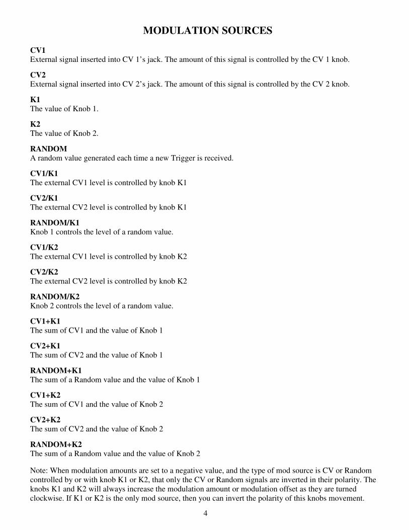
MODULATION SOURCES
CV1 External signal inserted into CV 1’s jack. The amount of this signal is controlled by the CV 1 knob.
CV2 External signal inserted into CV 2’s jack. The amount of this signal is controlled by the CV 2 knob.
K1 The value of Knob 1.
K2 The value of Knob 2.
RANDOM A random value generated each time a new Trigger is received.
CV1/K1 The external CV1 level is controlled by knob K1
CV2/K1 The external CV2 level is controlled by knob K1
RANDOM/K1 Knob 1 controls the level of a random value.
CV1/K2 The external CV1 level is controlled by knob K2
CV2/K2 The external CV2 level is controlled by knob K2
RANDOM/K2 Knob 2 controls the level of a random value.
CV1+K1
The sum of CV1 and the value of Knob 1
CV2+K1
The sum of CV2 and the value of Knob 1
RANDOM+K1 The sum of a Random value and the value of Knob 1
CV1+K2
The sum of CV1 and the value of Knob 2
CV2+K2
The sum of CV2 and the value of Knob 2
RANDOM+K2 The sum of a Random value and the value of Knob 2
Note: When modulation amounts are set to a negative value, and the type of mod source is CV or Random
controlled by or with knob K1 or K2, that only the CV or Random signals are inverted in their polarity. The
knobs K1 and K2 will always increase the modulation amount or modulation offset as they are turned
clockwise. If K1 or K2 is the only mod source, then you can invert the polarity of this knobs movement.
4
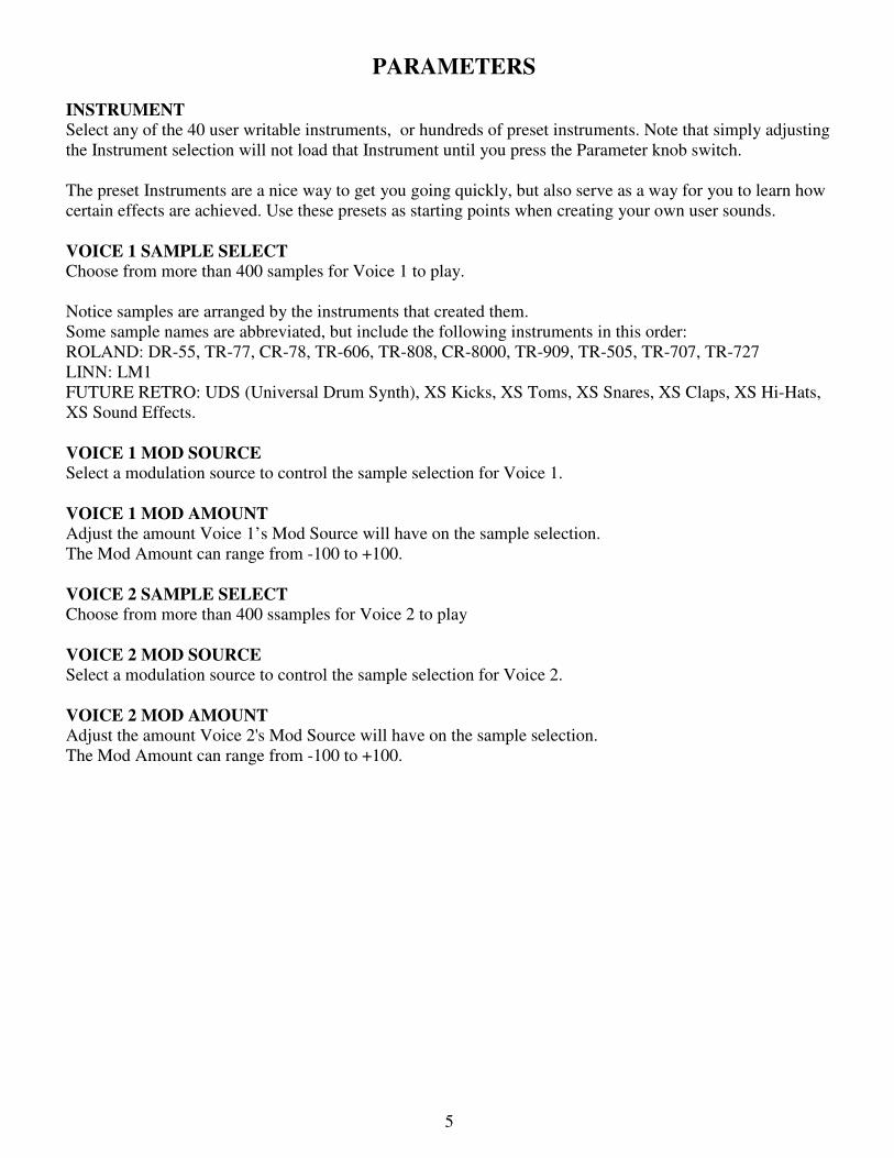
PARAMETERS
INSTRUMENT Select any of the 40 user writable instruments, or hundreds of preset instruments. Note that simply adjusting
the Instrument selection will not load that Instrument until you press the Parameter knob switch.
The preset Instruments are a nice way to get you going quickly, but also serve as a way for you to learn how
certain effects are achieved. Use these presets as starting points when creating your own user sounds.
VOICE 1 SAMPLE SELECT Choose from more than 400 samples for Voice 1 to play.
Notice samples are arranged by the instruments that created them.
Some sample names are abbreviated, but include the following instruments in this order:
ROLAND: DR-55, TR-77, CR-78, TR-606, TR-808, CR-8000, TR-909, TR-505, TR-707, TR-727
LINN: LM1
FUTURE RETRO: UDS (Universal Drum Synth), XS Kicks, XS Toms, XS Snares, XS Claps, XS Hi-Hats,
XS Sound Effects.
VOICE 1 MOD SOURCE Select a modulation source to control the sample selection for Voice 1.
VOICE 1 MOD AMOUNT Adjust the amount Voice 1’s Mod Source will have on the sample selection.
The Mod Amount can range from -100 to +100.
VOICE 2 SAMPLE SELECT Choose from more than 400 ssamples for Voice 2 to play
VOICE 2 MOD SOURCE Select a modulation source to control the sample selection for Voice 2.
VOICE 2 MOD AMOUNT Adjust the amount Voice 2's Mod Source will have on the sample selection.
The Mod Amount can range from -100 to +100.
5

MOD 1 Select how Mod 1 will affect the sound with the following options:
VOICE 1 - MUTE Mute all sound from Voice 1
VOICE 1 - BYPASS Play Voice 1's sample without any additional modulation.
VOICE 1 - AM OSC 1 Amplitude modulate Voice 1's sample with Oscillator 1.
VOICE 1 - AM OSC 2 Amplitude modulate Voice 1's sample with Oscillator 2.
VOICE 1 - AM SAMPLE 1 Amplitude modulate Voice 1's sample with itself.
VOICE 1 - AM SAMPLE 2 Amplitude modulate Voice 1's sample with Voice 2's sample.
VOICE 1 - RING OSC 1 Ring modulate Voice 1's sample with Oscillator 1.
VOICE 1 - RING OSC 2 Ring modulate Voice 1's sample with Oscillator 2.
VOICE 1 - RING SAMPLE 1 Ring modulate Voice 1's sample with itself.
VOICE 1 - RING SAMPLE 2 Ring modulate Voice 1's sample with Voice 2's sample.
MOD 2 OUT - AM OSC 1 Amplitude modulate Mod 2's output with Oscillator 1.
MOD 2 OUT - AM OSC 2 Amplitude modulate Mod 2's output with Oscillator 2.
MOD 2 OUT - AM SAMPLE 1 Amplitude modulate Mod 2's output with Voice 1's sample.
MOD 2 OUT - AM SAMPLE 2 Amplitude modulate Mod 2's output with Voice 2's sample.
MOD 2 OUT - RING OSC 1 Ring modulate Mod 2's output with Oscillator 1.
MOD 2 OUT - RING OSC 2 Ring modulate Mod 2's output with Oscillator 2.
MOD 2 OUT - RING SAMP1 Ring modulate Mod 2's output with Voice 1's sample.
MOD 2 OUT - RING SAMP2 Ring modulate Mod 2's output with Voice 2's sample.
MOD 1 GAIN Set the gain level for signal passing through Mod 1. Notice that a value of 100 is ideal. In some instances
when applying AM or Ring modulation you may find the signal needs a little extra boost. This gain level can
range from 0 to 200, providing up to 2x the normal level. Beware that higher gain settings may begin to clip
or overdrive the filter, so listen carefully to the effect gain has on the audio when making adjustments.
6

MOD 2 Select how Mod 2 will affect the sound with the following options:
VOICE 2 - MUTE Mute all sound from Voice 2
VOICE 2 - BYPASS Play Voice 2's sample without any additional modulation.
VOICE 2 - AM OSC 1 Amplitude modulate Voice 2's sample with Oscillator 1.
VOICE 2 - AM OSC 2 Amplitude modulate Voice 2's sample with Oscillator 2.
VOICE 2 - AM SAMPLE 1 Amplitude modulate Voice 2's sample with Voice 1's sample.
VOICE 2 - AM SAMPLE 2 Amplitude modulate Voice 2's sample with itself.
VOICE 2 - RING OSC 1 Ring modulate Voice 2's sample with Oscillator 1.
VOICE 2 - RING OSC 2 Ring modulate Voice 2's sample with Oscillator 2.
VOICE 2 - RING SAMPLE 1 Ring modulate Voice 2's sample with Voice 1's sample.
VOICE 2 - RING SAMPLE 2 Ring modulate Voice 2's sample with itself.
MOD 1 OUT - AM OSC 1 Amplitude modulate Mod 1's output with Oscillator 1.
MOD 1 OUT - AM OSC 2 Amplitude modulate Mod 1's output with Oscillator 2.
MOD 1 OUT - AM SAMPLE 1 Amplitude modulate Mod 1's output with Voice 1's sample.
MOD 1 OUT - AM SAMPLE 2 Amplitude modulate Mod 1's output with Voice 2's sample.
MOD 1 OUT - RING OSC 1 Ring modulate Mod 1's output with Oscillator 1.
MOD 1 OUT - RING OSC 2 Ring modulate Mod 1's output with Oscillator 2.
MOD 1 OUT - RING SAMP1 Ring modulate Mod 1's output with Voice 1's sample.
MOD 1 OUT - RING SAMP2 - Ring modulate Mod 1's output with Voice 2's sample.
MOD 2 GAIN Set the gain level for signal passing through Mod 2. Notice that a value of 100 is ideal. In some instances
when applying AM or Ring modulation you may find the signal needs a little extra boost. This gain level can
range from 0 to 200, providing up to 2x the normal level. Beware that higher gain settings may begin to clip
or overdrive the filter, so listen carefully to the affect gain has on the audio when making adjustments.
7

OSC 1 WAVEFORM Choose a waveform for Oscillator 1. Notices how some of these are traditional periodic waveforms, while
others look more like envelope shapes. Some waveforms will be more suitable for Ring modulation while
others are better for Amplitude modulation.
OSC 1 FREQUENCY Set the initial Frequency for Oscillator 1. This Frequency can range from 0.0Hz to 20,480Hz. Realize that
0.0Hz never oscillates, so the oscillator will generate the amplitude value for the wave at the phase it is synced
to, or can also act as a S/H function when the oscillator sync is off (free-running).
OSC 1 MOD SOURCE Select a modulation source to control the frequency or pitch of Oscillator 1.
OSC 1 MOD AMOUNT Adjust the amount of affect Osc 1's Mod Source will have on Oscillator 1's frequency or pitch. The Mod
Amount can range from -100 to +100. Notice that negative modulation amounts will cause positive polarity
modulation sources to lower Oscillator 1's frequency or pitch.
OSC 1 PHASE SYNC OFF/ON When the Phase Sync is set to OFF, Oscillator 1 will be free-running. When Phase Sync is set to ON,
Oscillator 1's waveform will restart at the defined Phase each time a new trigger is received.
OSC 1 PHASE Adjust the phase that Oscillator 1's waveform will start at each time a new trigger is received, when Phase
Sync is set to ON. The Phase can range in value from 0 to 360 degrees. A vertical bar is shown over the
waveform to indicate where the waveform will start.
OSC 1 PHASE MOD Select a modulation source to control Oscillator 1's Phase.
OSC 1 PHASE AMOUNT Adjust the amount of affect Osc 1's Phase Mod Source will have on Oscillator 1's Phase.
The Range is -100 to +100.
8

OSC 2 WAVEFORM Choose a waveform for Oscillator 2. Notices how some of these are traditional periodic waveforms, while
others look more like envelope shapes. Some waveforms will be more suitable for Ring modulation while
others are better for Amplitude modulation.
OSC 2 FREQUENCY Set the initial Frequency for Oscillator 2. This Frequency can range from 0.0Hz to 20,480Hz. Realize that
0.0Hz never oscillates, so the oscillator will generate the amplitude value for the wave at the phase it is synced
to, or can also act as a S/H function when the oscillator sync is off (free-running).
OSC 2 MOD SOURCE Select a modulation source to control the frequency or pitch of Oscillator 2.
OSC 2 MOD AMOUNT Adjust the amount of affect Osc 2's Mod Source will have on Oscillator 2's frequency or pitch.
The Mod Amount can range from -100 to +100.
OSC 2 PHASE SYNC OFF/ON When the Phase Sync is set to OFF, Oscillator 2 will be free-running. When Phase Sync is set to ON,
Oscillator 2's waveform will restart at the defined Phase each time a new trigger is received.
OSC 2 PHASE Adjust the phase that Oscillator 2's waveform will start at each time a new trigger is received, when Phase
Sync is set to ON. The Phase can range in value from 0 to 360 degrees. A vertical bar is shown over the
waveform to indicate where the waveform will start.
OSC 2 PHASE MOD Select a modulation source to control Oscillator 2's Phase.
OSC 2 PHASE AMOUNT Adjust the amount of affect Osc 2's Phase Mod Source will have on Oscillator 2's Phase.
The Range is -100 to +100.
9

MIX VOICE 1/2 Adjust the mix balance of Voice 1 to Voice 2.
The range is 0:100 to 100:0.
MIX MOD SOURCE Select a modulation source to control the Mix balance between Voice 1 and Voice 2.
MIX MOD AMOUNT Adjust the amount of affect the Mix Mod Source will have on the overall mix of Voice 1 and Voice 2.
The Mix modulation amount does have a unique characteristic in that a modulation range of 0v to +5v would
normally mix from Voice 1 to Voice 2 respectively with initial Mix values of Voice 1:100, Voice 2:000.
If the initial Mix values are set to Voice 1:000, Voice 2:100, a modulation of 0v to +5v will now mix from
Voice 2 to Voice 1 respectively.
Should you set the initial Mix values to Voice 1:050, Voice 2:050, a modulation value of 0v would play both
voices equally, a modulation value of +2.5v would play just Voice 2, and a modulation of +5v would again
play both voices equally.
This is due to the way that voltages wrap around the 0 to 100 mix range. Once a modulation tries to take the
mix higher than 100, it instead begins to decrease the mix value instead of increasing it.
Try playing with the initial Mix settings (or offsetting the modulation value with knob K1 or K2, using a mod
source like CV1+K1) when a source is set to modulate the Mix. It can really change the feel of things.
DIGITAL EFFECTS There are three digital effects to choose from and they are as follows:
COMPAND The Compand effect can be used to recreate the sound quality of early 80's drum machine sounds.
DISTORTION The Distortion effect cause low level signals to become more distorted.
BIT CRUSH The Bit Crush effect, degrades the sampling bit quality of the sound.
DIGITAL BITS This sets the number of digital bits used to process the audio.
The range is 1 to 12. Lower values will add distortion and noise to the currently selected Digital Effect.
A value of 12 prevents audio from being altered by the digital effect.
DIGITAL RATE This sets the resampling rate of the digital audio.
The range is from 1 to 35. A value of 35 provides unaltered audio at 44k sampling rate. Lower values will
decrease the sampling rate, and introduce additional harmonics and distortion.
10

FILTER TYPE A multi-mode filter is provided to process sounds.
While there is no Resonance control, there is a small amount of resonance applied internally to the Low,
Band, and High-pass filter types.
LOW PASS Select the Low pass filter to remove frequencies higher than Filter's Cutoff Frequency. BAND PASS Select the Band pass filter to allow only frequencies around the Filter's Cutoff Frequency to pass. HIGH PASS Select the High pass filter to remove frequencies lower than the Filter's Cutoff Frequency. ALL PASS The All Pass filter simply bypasses the filter altogether, meaning the filter has no effect at all on the audio.
FILTER FREQUENCY Set the Cutoff Frequency for the filter.
The filter's frequency can range from 16Hz to 14,868Hz.
FILTER MOD SOURCE Select a modulation source to control the Filter's Cutoff Frequency.
FILTER MOD AMOUNT Adjust the amount of affect the Filter Mod Source will have on filter's Cutoff Frequency.
The Mod Amount can range from -100 to +100.
DYNAMICS MOD SOURCE Select a modulation source to control the overall Dynamics (volume level) for sounds.
DYNAMICS LO RANGE This adjusts the lowest possible Dynamic level for the current Instrument. This level will occur when an
external CV is at 0v or when a knob is turned fully counter-clockwise. The Range is from 0 to 100. Keep in
mind that the Dynamic response can also be inverted by making the Lo Range a higher value than the Hi
Range.
DYNAMICS HI RANGE This adjusts the highest possible Dynamics level for the current Instrument. This level will occur when an
external CV is at +5v or when a knob is turned fully clockwise.
SAVE INSTRUMENT Here you can select one of the 40 User Instrument location to write the current instrument settings to.
Note that Preset Instrument locations can not be written to, however you can edit a preset sound and write it to
any of the 40 User locations.
SAVE INSTRUMENT - PRESS TO CONFIRM Once you have defined the User location to write the current Instrument settings to, this page allows you to
actually save the Instrument by pressing the Parameter knob switch. When the instrument is successfully
saved you will see "INSTRUMENT WAS SAVED!" on the display. This message will remain on the display
until you move the Parameter knob to select a different parameter.
11

TROUBLESHOOTING
Always use caution when handling the Transient. Make sure to discharge yourself of any static electricity
before touching the unit. When installing and removing the module from your system, hold the unit at the
edge of the front panel to avoid your fingers from coming in contact with the circuitry. Keep your original
packaging in case you ever need to ship your product. This unit should always be placed in an anti-static bag
during shipping.
Pay very close attention when installing the Transient into your system, so that the red-strip of the power
ribbon cable is aligned with the -12v on both the Transient and your system’s power distribution connector.
Make sure your system provides +5v, +12v, and -12v power. Some systems only provide +12v and -12v, and
without the +5v power the Transient simply will not work.
Also make sure you know how much current your system can provide for each voltage level, and how much
current the modules in your system are drawing from the power supply. If your system is unable to provide
enough current for each module in your system, obviously something is not going to work as expected or
perhaps at all.
If your unit ever behaves in an unexpected way, turn the unit off, and then back on again.
If the unit appears to be unresponsive to external CV signals, first make sure that CV is assigned to
modulation at least one parameter in the Instrument. Also make sure the CV1 or CV2 attenuator knobs are
turned up as well. If you still hear no change, double check that the device connecting to the Transient’s CV
input is actually generating voltages. And finally, try using a different patch cable, they do go bad over time.
If you do not hear any audio at the output, first select a simply preset Instrument like “Start Here”.
Make sure that a signal is inserted into the Trig In jack and that this source signal is generating some sort of
trigger signal. Check to see that audio is being routed from the Audio Out jack to a mixer, amplifier and some
form of speakers.
If you failed to select the “Start Here” preset, then you should also look to see if MOD 1 or MOD 2 is set to
Mute, and double check your settings for the Lo/Hi Range of Dynamics.
If you have other questions or you experience problems not addressed in this manual, please check the
Support page of our web site: www.future-retro.com/support.html or try downloading the latest version of this
manual.
INITIALIZING THE UNIT
Warning: Initializing the unit will reset your Transient causing all the user sound memories to default to the
Instrument preset "start here". This will erase any sounds you might have previously made and stored in the
user Instrument memory locations.
To initialize the unit, start with the unit powered off. Press and hold the parameter select knob, and turn the
power on. Continue to press the parameter select knob until the display reads "initialize unit?" Release the
parameter select switch, and press then press the switch again to confirm and initialize the unit. To abort this
operation, simply turn the parameter select knob.
12
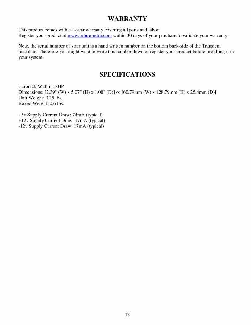
WARRANTY
This product comes with a 1-year warranty covering all parts and labor.
Register your product at www.future-retro.com within 30 days of your purchase to validate your warranty.
Note, the serial number of your unit is a hand written number on the bottom back-side of the Transient
faceplate. Therefore you might want to write this number down or register your product before installing it in
your system.
SPECIFICATIONS
Eurorack Width: 12HP
Dimensions: [2.39" (W) x 5.07" (H) x 1.00" (D)] or [60.79mm (W) x 128.79mm (H) x 25.4mm (D)]
Unit Weight: 0.25 lbs.
Boxed Weight: 0.6 lbs.
+5v Supply Current Draw: 74mA (typical) +12v Supply Current Draw: 17mA (typical)
-12v Supply Current Draw: 17mA (typical)
13