w:projectstelecomunicationsat&tctct2157 · pdf fileappurtenances configuration: tenant...
TRANSCRIPT


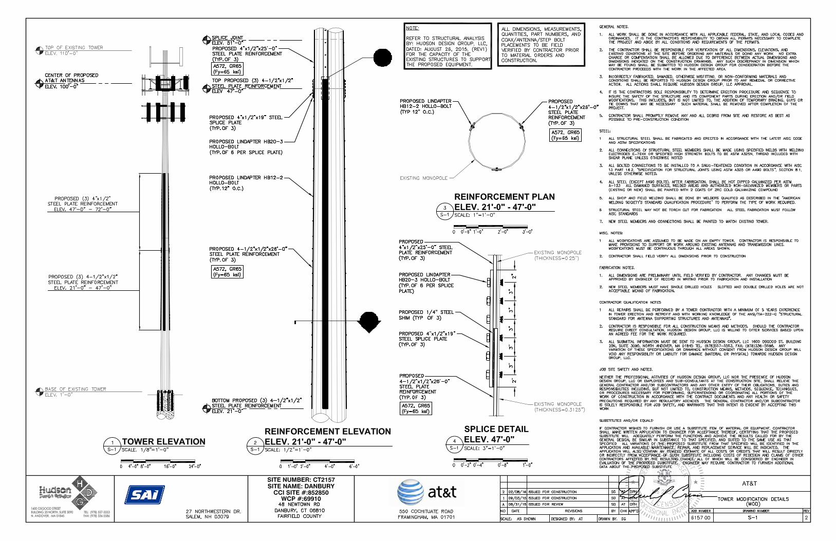


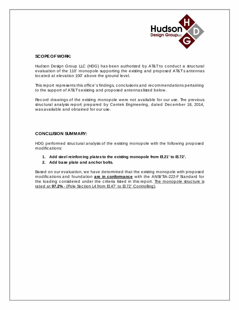
SCOPE OF WORK: Hudson Design Group LLC (HDG) has been authorized by AT&T to conduct a structural evaluation of the 110’ monopole supporting the existing and proposed AT&T’s antennas located at elevation 100’ above the ground level. This report represents this office’s findings, conclusions and recommendations pertaining to the support of AT&T’s existing and proposed antennas listed below. Record drawings of the existing monopole were not available for our use. The previous structural analysis report prepared by Centek Engineering, dated December 18, 2014, was available and obtained for our use. CONCLUSION SUMMARY: HDG performed structural analysis of the existing monopole with the following proposed modifications:
1. Add steel reinforcing plates to the existing monopole from El.21’ to El.72’. 2. Add base plate and anchor bolts.
Based on our evaluation, we have determined that the existing monopole with proposed modifications and foundation are in conformance with the ANSI/TIA-222-F Standard for the loading considered under the criteria listed in this report. The monopole structure is rated at 97.2% - (Pole Section L4 from El.47’ to El.72’ Controlling).
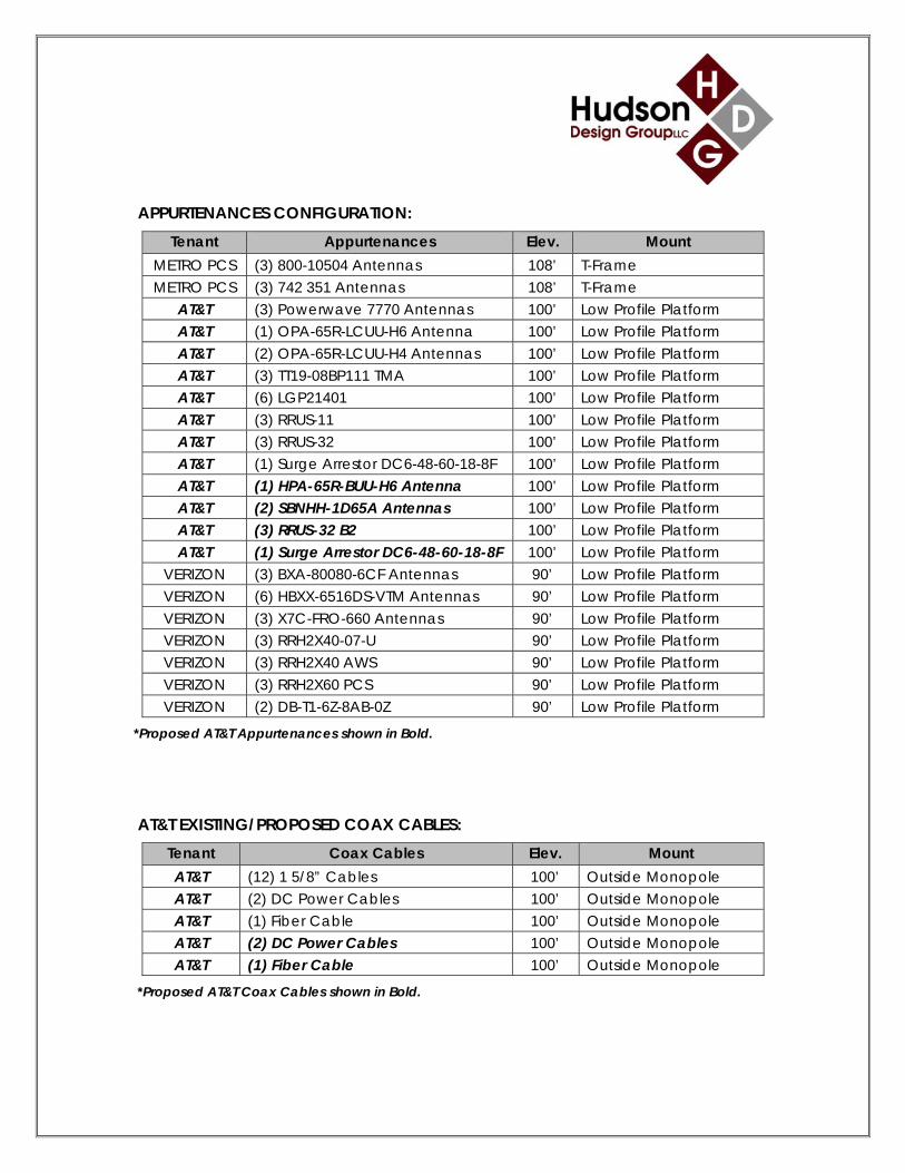
APPURTENANCES CONFIGURATION:
Tenant Appurtenances Elev. Mount METRO PCS (3) 800-10504 Antennas 108’ T-Frame METRO PCS (3) 742 351 Antennas 108’ T-Frame
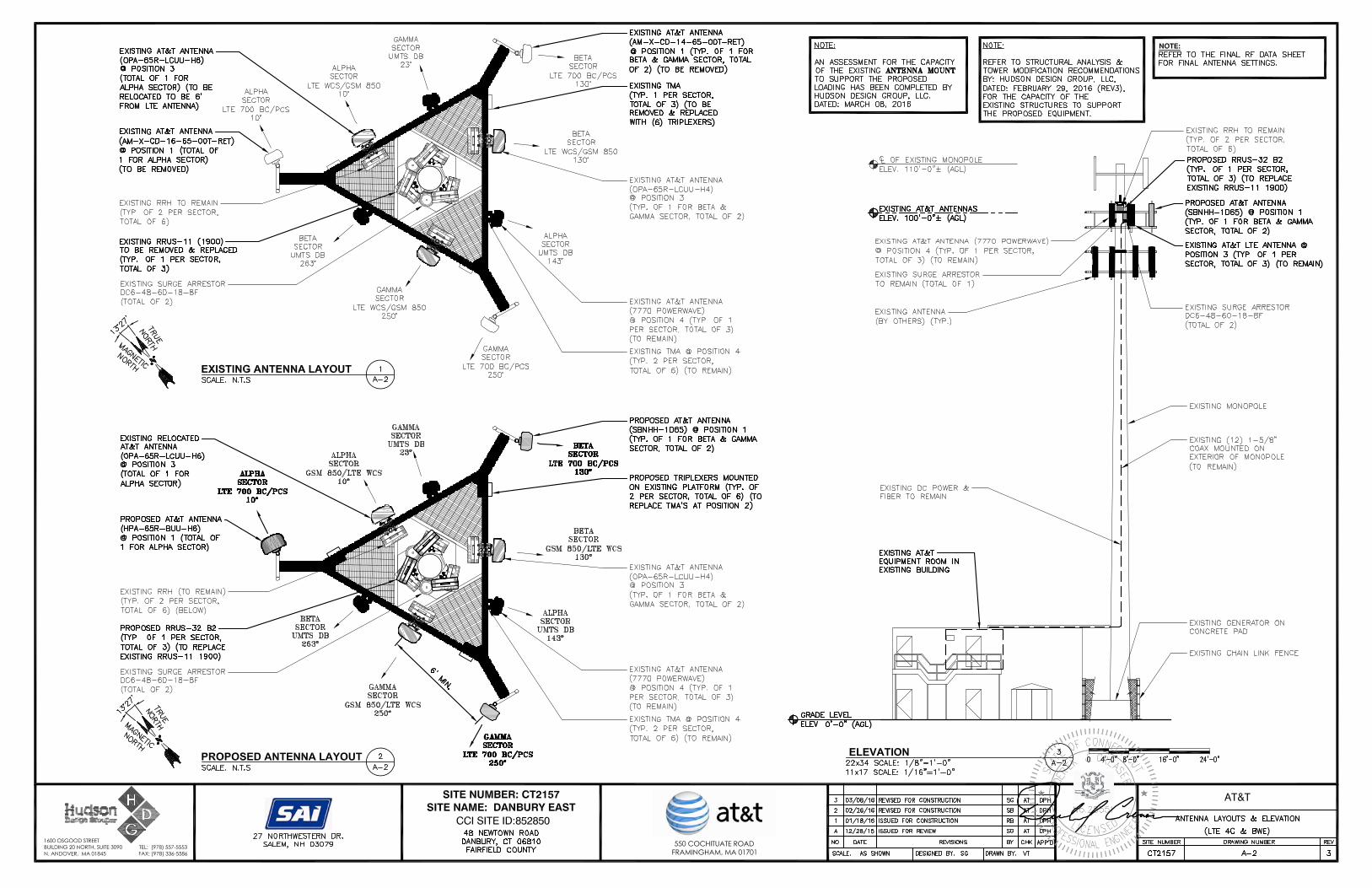
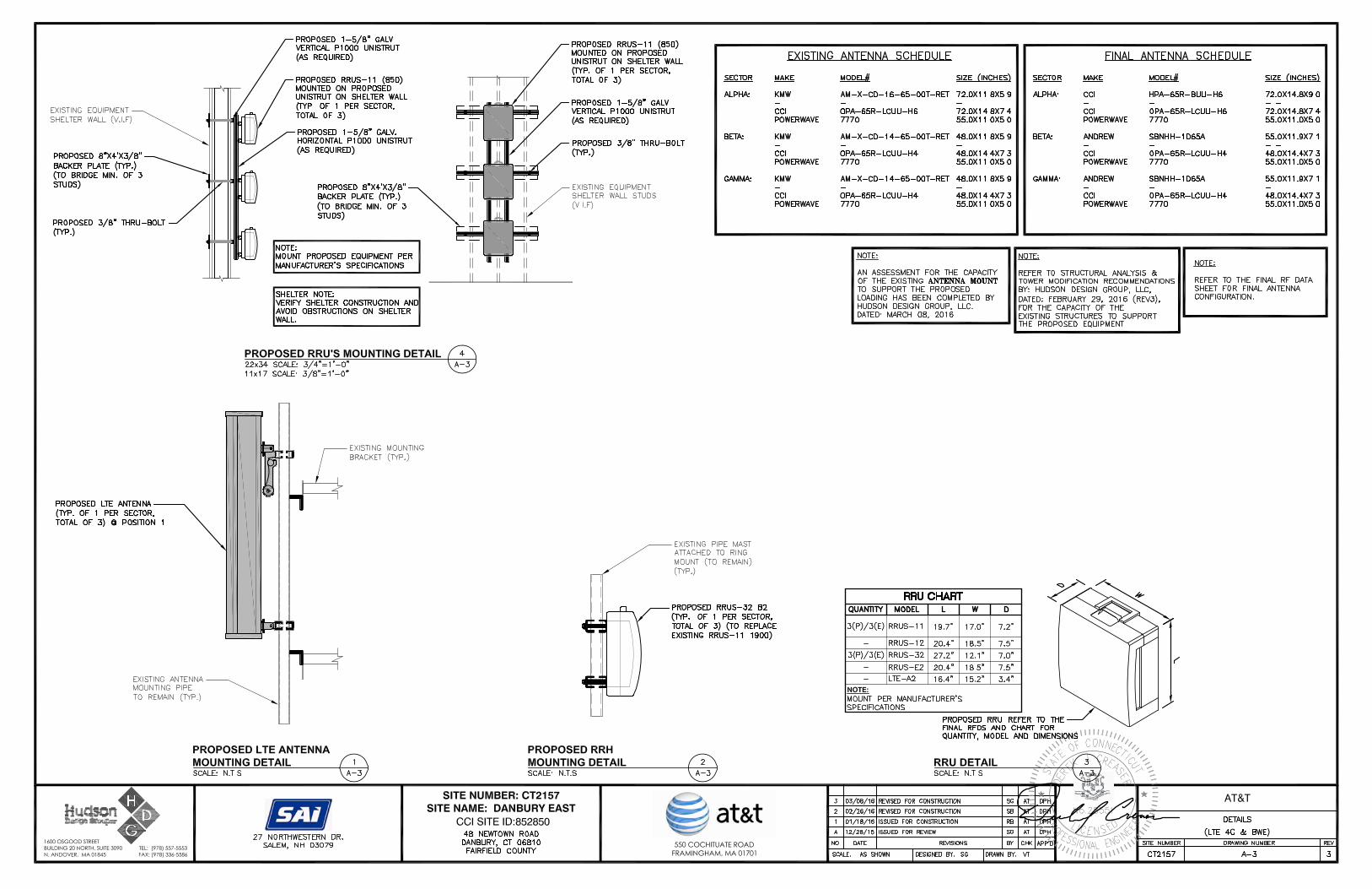
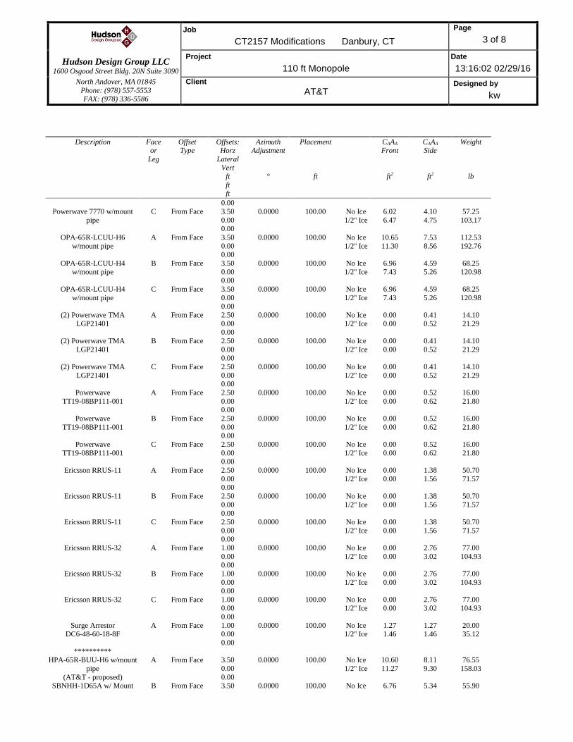
AT&T (3) Powerwave 7770 Antennas 100’ Low Profile Platform AT&T (1) OPA-65R-LCUU-H6 Antenna 100’ Low Profile Platform AT&T (2) OPA-65R-LCUU-H4 Antennas 100’ Low Profile Platform AT&T (3) TT19-08BP111 TMA 100’ Low Profile Platform AT&T (6) LGP21401 100’ Low Profile Platform AT&T (3) RRUS-11 100’ Low Profile Platform AT&T (3) RRUS-32 100’ Low Profile Platform AT&T (1) Surge Arrestor DC6-48-60-18-8F 100’ Low Profile Platform AT&T (1) HPA-65R-BUU-H6 Antenna 100’ Low Profile Platform AT&T (2) SBNHH-1D65A Antennas 100’ Low Profile Platform AT&T (3) RRUS-32 B2 100’ Low Profile Platform AT&T (1) Surge Arrestor DC6-48-60-18-8F 100’ Low Profile Platform
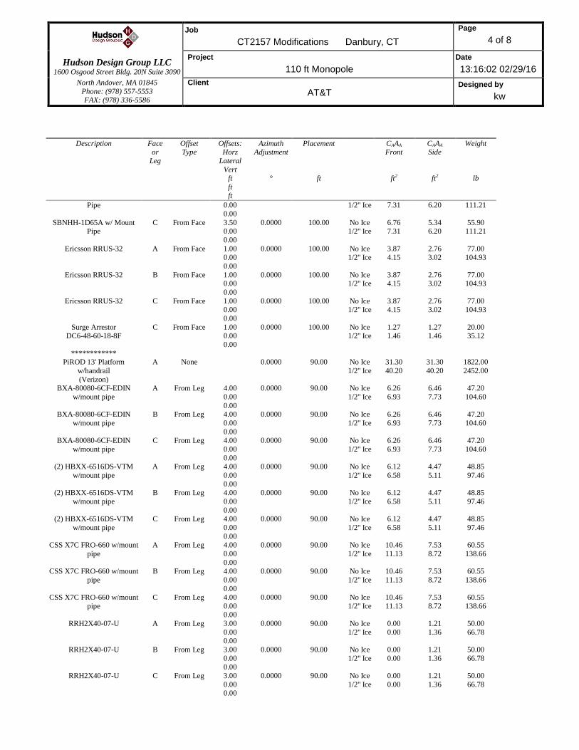
VERIZON (3) BXA-80080-6CF Antennas 90’ Low Profile Platform VERIZON (6) HBXX-6516DS-VTM Antennas 90’ Low Profile Platform VERIZON (3) X7C-FRO-660 Antennas 90’ Low Profile Platform VERIZON (3) RRH2X40-07-U 90’ Low Profile Platform VERIZON (3) RRH2X40 AWS 90’ Low Profile Platform VERIZON (3) RRH2X60 PCS 90’ Low Profile Platform VERIZON (2) DB-T1-6Z-8AB-0Z 90’ Low Profile Platform
*Proposed AT&T Appurtenances shown in Bold. AT&T EXISTING/PROPOSED COAX CABLES:
Tenant Coax Cables Elev. Mount AT&T (12) 1 5/8” Cables 100’ Outside Monopole AT&T (2) DC Power Cables 100’ Outside Monopole AT&T (1) Fiber Cable 100’ Outside Monopole AT&T (2) DC Power Cables 100’ Outside Monopole AT&T (1) Fiber Cable 100’ Outside Monopole
*Proposed AT&T Coax Cables shown in Bold.
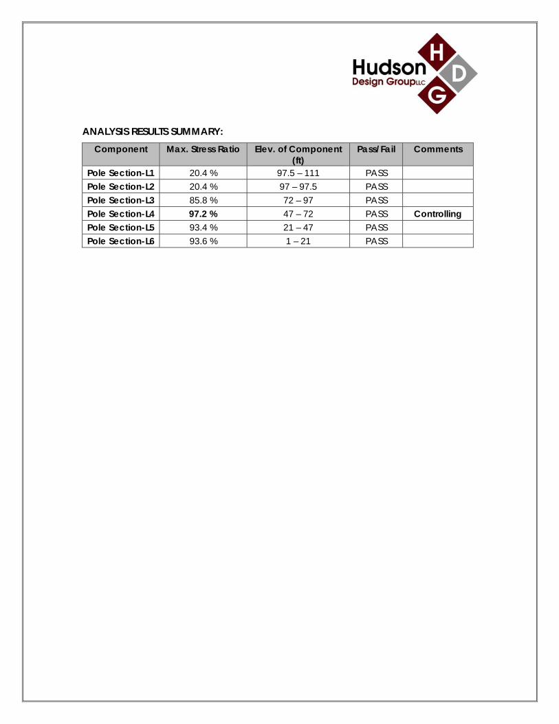
ANALYSIS RESULTS SUMMARY:
Component Max. Stress Ratio Elev. of Component (ft)
Pass/Fail Comments
Pole Section-L1 20.4 % 97.5 – 111 PASS Pole Section-L2 20.4 % 97 – 97.5 PASS Pole Section-L3 85.8 % 72 – 97 PASS Pole Section-L4 97.2 % 47 – 72 PASS Controlling Pole Section-L5 93.4 % 21 – 47 PASS Pole Section-L6 93.6 % 1 – 21 PASS

DESIGN CRITERIA:
1. EIA/TIA-222-F Structural Standards for Steel Antenna Towers and Antenna Supporting Structures
City/Town: Danbury County: Fairfield Wind Load: 85 mph (fastest mile)
105 mph (3 second gust) Nominal Ice Thickness: 1/2 inch
2. Approximate height above grade to proposed antennas: 100’
*Calculations and referenced documents are attached. ASSUMPTIONS:
1. The monopole dimensions, member sizes, material strength and foundation are as indicated in the previous structural analysis report prepared by Centek Engineering, dated December 18, 2014.
2. The appurtenances configuration is as stated in the previous structural analysis report prepared by Centek Engineering, dated December 18, 2014. All antennas, coax cables and waveguide cables are assumed to be properly installed and supported as per the manufacturer’s requirements.
3. The monopole and foundation are properly constructed and maintained. All
structural members and their connections are assumed to be in good condition and are free from defects with no deterioration to its member capacities.
4. The support mounts and platforms are not analyzed and are considered adequate to support the loading. The analysis is limited to the primary support structure itself.
5. All prior structural modification, if any, are assumed to be as per the data supplied (if available), and installed properly.

SUPPORT RECOMMENDATIONS: HDG recommends that the proposed antennas be mounted on the existing steel platform supported by the monopole; the proposed RRHs and surge arrestor be mounted on the mount pipes. Reference HDG’s Latest Construction Drawings for all component and connection requirements (attached). ONGOING AND PERIODIC INSPTECTION AND MAINTENANCE: After the Contractor has successfully completed the installation and the work has been accepted, the Owner will be responsible for the ongoing and periodic inspection and maintenance of the tower. The owner shall refer to TIA/EIA-222-F for recommendations for maintenance and inspection. The frequency of the inspection and maintenance intervals is to be determined by the owner based upon actual site and environmental conditions. It is recommended that a complete and thorough inspection of the entire tower structural system be performed at least yearly and more frequently as conditions warrant. According to TIA/EIA-222-F section 14.1, Note 1: It is recommended that the structure be inspected after severe wind and/or ice storms or other extreme loading conditions.
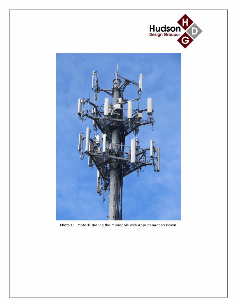
Photo 1: Photo illustrating the monopole with Appurtenances shown.

CALCULATIONS


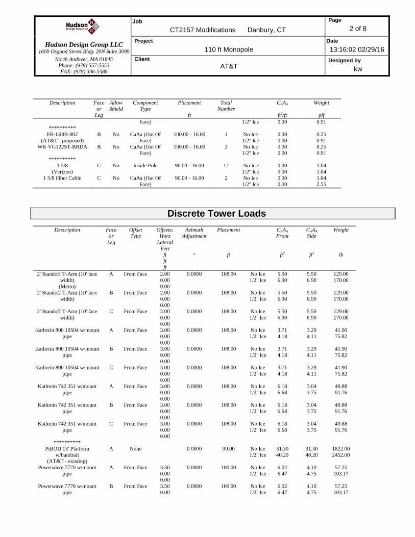
Job
CT2157 Modifications Danbury, CT
Page
1 of 8
Hudson Design Group LLC
1600 Osgood Street Bldg. 20N Suite 3090
Project
110 ft Monopole
Date
13:16:02 02/29/16
North Andover, MA 01845
Phone: (978) 557-5553 FAX: (978) 336-5586
Client
AT&T Designed by
kw
Tower Input Data
There is a pole section.
This tower is designed using the TIA/EIA-222-F standard.
The following design criteria apply:
Tower is located in Fairfield County, Connecticut.
Basic wind speed of 85.0 mph.
Nominal ice thickness of 0.5000 in.
Ice density of 56.0 pcf.
A wind speed of 73.6 mph is used in combination with ice.
Temperature drop of 50.0 °F.
Deflections calculated using a wind speed of 50.0 mph.
A non-linear (P-delta) analysis was used.
Pressures are calculated at each section.
Stress ratio used in pole design is 1.333.
Local bending stresses due to climbing loads, feed line supports, and appurtenance mounts are not considered.
Tapered Pole Section Geometry
Section Elevation
ft
Section
Length ft
Splice
Length ft
Number
of Sides
Top
Diameter in
Bottom
Diameter in
Wall
Thickness in
Bend
Radius in
Pole Grade
L1 111.00-97.50 13.50 0.00 Round 16.0000 16.0000 0.3750 A36
(36 ksi) L2 97.50-97.00 0.50 0.00 Round 16.0000 17.4900 0.3750 A36
(36 ksi)
L3 97.00-72.00 25.00 0.00 18 17.4900 22.7350 0.2500 1.0000 A572-65 (65 ksi)
L4 72.00-47.00 25.00 4.00 18 22.7350 27.9800 0.3000 1.2000 A572-65
(65 ksi) L5 47.00-21.00 30.00 0.00 18 26.5408 33.3920 0.3650 1.4600 A572-65
(65 ksi)
L6 21.00-1.00 20.00 18 33.3920 37.0000 0.3890 1.5560 A572-65 (65 ksi)
Feed Line/Linear Appurtenances - Entered As Area
Description Face
or
Leg
Allow
Shield
Component
Type
Placement
ft
Total
Number
CAAA
ft2/ft
Weight
plf
1 5/8 (Metro)
C No CaAa (Out Of Face)
109.00 - 16.00 2 No Ice 1/2'' Ice
0.20 0.30
1.04 2.55
1 5/8
(Metro)
C No CaAa (Out Of
Face)
109.00 - 16.00 10 No Ice
1/2'' Ice
0.00
0.00
1.04
2.55 **********
1 5/8
(AT&T - existing)
B No CaAa (Out Of
Face)
100.00 - 16.00 2 No Ice
1/2'' Ice
0.20
0.30
1.04
2.55 1 5/8
(AT&T - existing)
B No CaAa (Out Of
Face)
100.00 - 16.00 10 No Ice
1/2'' Ice
0.00
0.00
1.04
2.55
WR-VG122ST-BRDA B No CaAa (Out Of Face)
100.00 - 16.00 2 No Ice 1/2'' Ice
0.00 0.00
0.25 0.91
FB-L98B-002 B No CaAa (Out Of 100.00 - 16.00 1 No Ice 0.00 0.25
Job
CT2157 Modifications Danbury, CT
Page
2 of 8
Hudson Design Group LLC
1600 Osgood Street Bldg. 20N Suite 3090
Project
110 ft Monopole
Date
13:16:02 02/29/16
North Andover, MA 01845
Phone: (978) 557-5553 FAX: (978) 336-5586
Client
AT&T Designed by
kw
Description Face or
Leg
Allow Shield
Component Type
Placement
ft
Total Number
CAAA
ft2/ft
Weight
plf
Face) 1/2'' Ice 0.00 0.91 **********
FB-L98B-002
(AT&T - proposed)
B No CaAa (Out Of
Face)
100.00 - 16.00 1 No Ice
1/2'' Ice
0.00
0.00
0.25
0.91 WR-VG122ST-BRDA B No CaAa (Out Of
Face)
100.00 - 16.00 2 No Ice
1/2'' Ice
0.00
0.00
0.25
0.91
********** 1 5/8
(Verizon)
C No Inside Pole 90.00 - 16.00 12 No Ice
1/2'' Ice
0.00
0.00
1.04
1.04
1 5/8 Fiber Cable C No CaAa (Out Of Face)
90.00 - 16.00 2 No Ice 1/2'' Ice
0.00 0.00
1.04 2.55
Discrete Tower Loads
Description Face or
Leg
Offset Type
Offsets: Horz
Lateral
Vert ft
ft ft
Azimuth Adjustment
°
Placement
ft
CAAA Front
ft2
CAAA Side
ft2
Weight
lb
2' Standoff T-Arm (10' face
width)
(Metro)
A From Face 2.00
0.00
0.00
0.0000 108.00 No Ice
1/2'' Ice
5.50
6.90
5.50
6.90
129.00
170.00
2' Standoff T-Arm (10' face
width)
B From Face 2.00
0.00
0.00
0.0000 108.00 No Ice
1/2'' Ice
5.50
6.90
5.50
6.90
129.00
170.00
2' Standoff T-Arm (10' face
width)
C From Face 2.00
0.00
0.00
0.0000 108.00 No Ice
1/2'' Ice
5.50
6.90
5.50
6.90
129.00
170.00
Kathrein 800 10504 w/mount
pipe
A From Face 3.00
0.00
0.00
0.0000 108.00 No Ice
1/2'' Ice
3.71
4.18
3.29
4.11
41.90
75.82
Kathrein 800 10504 w/mount
pipe
B From Face 3.00
0.00
0.00
0.0000 108.00 No Ice
1/2'' Ice
3.71
4.18
3.29
4.11
41.90
75.82
Kathrein 800 10504 w/mount
pipe
C From Face 3.00
0.00
0.00
0.0000 108.00 No Ice
1/2'' Ice
3.71
4.18
3.29
4.11
41.90
75.82
Kathrein 742 351 w/mount
pipe
A From Face 3.00
0.00
0.00
0.0000 108.00 No Ice
1/2'' Ice
6.18
6.68
3.04
3.75
49.88
91.76
Kathrein 742 351 w/mount
pipe
B From Face 3.00
0.00
0.00
0.0000 108.00 No Ice
1/2'' Ice
6.18
6.68
3.04
3.75
49.88
91.76
Kathrein 742 351 w/mount
pipe
C From Face 3.00
0.00
0.00
0.0000 108.00 No Ice
1/2'' Ice
6.18
6.68
3.04
3.75
49.88
91.76
**********
PiROD 13' Platform
w/handrail (AT&T - existing)
A None 0.0000 99.00 No Ice
1/2'' Ice
31.30
40.20
31.30
40.20
1822.00
2452.00
Powerwave 7770 w/mount
pipe
A From Face 3.50
0.00 0.00
0.0000 100.00 No Ice
1/2'' Ice
6.02
6.47
4.10
4.75
57.25
103.17
Powerwave 7770 w/mount
pipe
B From Face 3.50
0.00
0.0000 100.00 No Ice
1/2'' Ice
6.02
6.47
4.10
4.75
57.25
103.17
Job
CT2157 Modifications Danbury, CT
Page
3 of 8
Hudson Design Group LLC
1600 Osgood Street Bldg. 20N Suite 3090
Project
110 ft Monopole
Date
13:16:02 02/29/16
North Andover, MA 01845
Phone: (978) 557-5553 FAX: (978) 336-5586
Client
AT&T Designed by
kw
Description Face or
Leg
Offset Type
Offsets: Horz
Lateral
Vert ft
ft
ft
Azimuth Adjustment
°
Placement
ft
CAAA Front
ft2
CAAA Side
ft2
Weight
lb
0.00
Powerwave 7770 w/mount
pipe
C From Face 3.50
0.00 0.00
0.0000 100.00 No Ice
1/2'' Ice
6.02
6.47
4.10
4.75
57.25
103.17
OPA-65R-LCUU-H6
w/mount pipe
A From Face 3.50
0.00 0.00
0.0000 100.00 No Ice
1/2'' Ice
10.65
11.30
7.53
8.56
112.53
192.76
OPA-65R-LCUU-H4
w/mount pipe
B From Face 3.50
0.00 0.00
0.0000 100.00 No Ice
1/2'' Ice
6.96
7.43
4.59
5.26
68.25
120.98
OPA-65R-LCUU-H4
w/mount pipe
C From Face 3.50
0.00 0.00
0.0000 100.00 No Ice
1/2'' Ice
6.96
7.43
4.59
5.26
68.25
120.98
(2) Powerwave TMA
LGP21401
A From Face 2.50
0.00 0.00
0.0000 100.00 No Ice
1/2'' Ice
0.00
0.00
0.41
0.52
14.10
21.29
(2) Powerwave TMA
LGP21401
B From Face 2.50
0.00 0.00
0.0000 100.00 No Ice
1/2'' Ice
0.00
0.00
0.41
0.52
14.10
21.29
(2) Powerwave TMA
LGP21401
C From Face 2.50
0.00 0.00
0.0000 100.00 No Ice
1/2'' Ice
0.00
0.00
0.41
0.52
14.10
21.29
Powerwave
TT19-08BP111-001
A From Face 2.50
0.00
0.00
0.0000 100.00 No Ice
1/2'' Ice
0.00
0.00
0.52
0.62
16.00
21.80
Powerwave
TT19-08BP111-001
B From Face 2.50
0.00 0.00
0.0000 100.00 No Ice
1/2'' Ice
0.00
0.00
0.52
0.62
16.00
21.80
Powerwave
TT19-08BP111-001
C From Face 2.50
0.00 0.00
0.0000 100.00 No Ice
1/2'' Ice
0.00
0.00
0.52
0.62
16.00
21.80
Ericsson RRUS-11 A From Face 2.50
0.00 0.00
0.0000 100.00 No Ice
1/2'' Ice
0.00
0.00
1.38
1.56
50.70
71.57
Ericsson RRUS-11 B From Face 2.50
0.00 0.00
0.0000 100.00 No Ice
1/2'' Ice
0.00
0.00
1.38
1.56
50.70
71.57
Ericsson RRUS-11 C From Face 2.50
0.00 0.00
0.0000 100.00 No Ice
1/2'' Ice
0.00
0.00
1.38
1.56
50.70
71.57
Ericsson RRUS-32 A From Face 1.00
0.00
0.00
0.0000 100.00 No Ice
1/2'' Ice
0.00
0.00
2.76
3.02
77.00
104.93
Ericsson RRUS-32 B From Face 1.00
0.00 0.00
0.0000 100.00 No Ice
1/2'' Ice
0.00
0.00
2.76
3.02
77.00
104.93
Ericsson RRUS-32 C From Face 1.00 0.00
0.00
0.0000 100.00 No Ice 1/2'' Ice
0.00 0.00
2.76 3.02
77.00 104.93
Surge Arrestor DC6-48-60-18-8F
A From Face 1.00 0.00
0.00
0.0000 100.00 No Ice 1/2'' Ice
1.27 1.46
1.27 1.46
20.00 35.12
********** HPA-65R-BUU-H6 w/mount
pipe
(AT&T - proposed)
A From Face 3.50
0.00
0.00
0.0000 100.00 No Ice
1/2'' Ice
10.60
11.27
8.11
9.30
76.55
158.03
SBNHH-1D65A w/ Mount B From Face 3.50 0.0000 100.00 No Ice 6.76 5.34 55.90
Job
CT2157 Modifications Danbury, CT
Page
4 of 8
Hudson Design Group LLC
1600 Osgood Street Bldg. 20N Suite 3090
Project
110 ft Monopole
Date
13:16:02 02/29/16
North Andover, MA 01845
Phone: (978) 557-5553 FAX: (978) 336-5586
Client
AT&T Designed by
kw
Description Face or
Leg
Offset Type
Offsets: Horz
Lateral
Vert ft
ft
ft
Azimuth Adjustment
°
Placement
ft
CAAA Front
ft2
CAAA Side
ft2
Weight
lb
Pipe 0.00
0.00
1/2'' Ice 7.31 6.20 111.21
SBNHH-1D65A w/ Mount Pipe
C From Face 3.50 0.00
0.00
0.0000 100.00 No Ice 1/2'' Ice
6.76 7.31
5.34 6.20
55.90 111.21
Ericsson RRUS-32 A From Face 1.00 0.00
0.00
0.0000 100.00 No Ice 1/2'' Ice
3.87 4.15
2.76 3.02
77.00 104.93
Ericsson RRUS-32 B From Face 1.00 0.00
0.00
0.0000 100.00 No Ice 1/2'' Ice
3.87 4.15
2.76 3.02
77.00 104.93
Ericsson RRUS-32 C From Face 1.00 0.00
0.00
0.0000 100.00 No Ice 1/2'' Ice
3.87 4.15
2.76 3.02
77.00 104.93
Surge Arrestor DC6-48-60-18-8F
C From Face 1.00 0.00
0.00
0.0000 100.00 No Ice 1/2'' Ice
1.27 1.46
1.27 1.46
20.00 35.12
************ PiROD 13' Platform
w/handrail
(Verizon)
A None 0.0000 90.00 No Ice
1/2'' Ice
31.30
40.20
31.30
40.20
1822.00
2452.00
BXA-80080-6CF-EDIN
w/mount pipe
A From Leg 4.00
0.00
0.00
0.0000 90.00 No Ice
1/2'' Ice
6.26
6.93
6.46
7.73
47.20
104.60
BXA-80080-6CF-EDIN
w/mount pipe
B From Leg 4.00
0.00
0.00
0.0000 90.00 No Ice
1/2'' Ice
6.26
6.93
6.46
7.73
47.20
104.60
BXA-80080-6CF-EDIN
w/mount pipe
C From Leg 4.00
0.00
0.00
0.0000 90.00 No Ice
1/2'' Ice
6.26
6.93
6.46
7.73
47.20
104.60
(2) HBXX-6516DS-VTM
w/mount pipe
A From Leg 4.00
0.00
0.00
0.0000 90.00 No Ice
1/2'' Ice
6.12
6.58
4.47
5.11
48.85
97.46
(2) HBXX-6516DS-VTM
w/mount pipe
B From Leg 4.00
0.00
0.00
0.0000 90.00 No Ice
1/2'' Ice
6.12
6.58
4.47
5.11
48.85
97.46
(2) HBXX-6516DS-VTM
w/mount pipe
C From Leg 4.00
0.00
0.00
0.0000 90.00 No Ice
1/2'' Ice
6.12
6.58
4.47
5.11
48.85
97.46
CSS X7C FRO-660 w/mount
pipe
A From Leg 4.00
0.00
0.00
0.0000 90.00 No Ice
1/2'' Ice
10.46
11.13
7.53
8.72
60.55
138.66
CSS X7C FRO-660 w/mount
pipe
B From Leg 4.00
0.00
0.00
0.0000 90.00 No Ice
1/2'' Ice
10.46
11.13
7.53
8.72
60.55
138.66
CSS X7C FRO-660 w/mount
pipe
C From Leg 4.00
0.00 0.00
0.0000 90.00 No Ice
1/2'' Ice
10.46
11.13
7.53
8.72
60.55
138.66
RRH2X40-07-U A From Leg 3.00
0.00 0.00
0.0000 90.00 No Ice
1/2'' Ice
0.00
0.00
1.21
1.36
50.00
66.78
RRH2X40-07-U B From Leg 3.00
0.00 0.00
0.0000 90.00 No Ice
1/2'' Ice
0.00
0.00
1.21
1.36
50.00
66.78
RRH2X40-07-U C From Leg 3.00
0.00 0.00
0.0000 90.00 No Ice
1/2'' Ice
0.00
0.00
1.21
1.36
50.00
66.78

Job
CT2157 Modifications Danbury, CT
Page
5 of 8
Hudson Design Group LLC
1600 Osgood Street Bldg. 20N Suite 3090
Project
110 ft Monopole
Date
13:16:02 02/29/16
North Andover, MA 01845
Phone: (978) 557-5553 FAX: (978) 336-5586
Client
AT&T Designed by
kw
Description Face or
Leg
Offset Type
Offsets: Horz
Lateral
Vert ft
ft
ft
Azimuth Adjustment
°
Placement
ft
CAAA Front
ft2
CAAA Side
ft2
Weight
lb
RRH2X40 AWS A From Leg 3.00
0.00
0.00
0.0000 90.00 No Ice
1/2'' Ice
2.52
2.75
1.59
1.80
44.00
61.40
RRH2X40 AWS B From Leg 3.00
0.00
0.00
0.0000 90.00 No Ice
1/2'' Ice
2.52
2.75
1.59
1.80
44.00
61.40
RRH2X40 AWS C From Leg 3.00
0.00
0.00
0.0000 90.00 No Ice
1/2'' Ice
2.52
2.75
1.59
1.80
44.00
61.40
RRH2x60 PCS A From Leg 3.00
0.00
0.00
0.0000 90.00 No Ice
1/2'' Ice
2.51
2.73
1.55
1.74
55.00
72.75
RRH2x60 PCS B From Leg 3.00
0.00
0.00
0.0000 90.00 No Ice
1/2'' Ice
2.51
2.73
1.55
1.74
55.00
72.75
RRH2x60 PCS C From Leg 3.00
0.00
0.00
0.0000 90.00 No Ice
1/2'' Ice
2.51
2.73
1.55
1.74
55.00
72.75
RFS DB-T1-6Z-8AB-0Z A From Leg 3.00
0.00
0.00
0.0000 90.00 No Ice
1/2'' Ice
5.60
5.92
2.33
2.56
44.00
80.13
RFS DB-T1-6Z-8AB-0Z B From Leg 3.00
0.00
0.00
0.0000 90.00 No Ice
1/2'' Ice
5.60
5.92
2.33
2.56
44.00
80.13
Load Combinations
Comb. No.
Description
1 Dead Only
2 Dead+Wind 0 deg - No Ice
3 Dead+Wind 30 deg - No Ice 4 Dead+Wind 60 deg - No Ice
5 Dead+Wind 90 deg - No Ice
6 Dead+Wind 120 deg - No Ice 7 Dead+Wind 150 deg - No Ice
8 Dead+Wind 180 deg - No Ice
9 Dead+Wind 210 deg - No Ice 10 Dead+Wind 240 deg - No Ice
11 Dead+Wind 270 deg - No Ice
12 Dead+Wind 300 deg - No Ice 13 Dead+Wind 330 deg - No Ice
14 Dead+Ice+Temp
15 Dead+Wind 0 deg+Ice+Temp 16 Dead+Wind 30 deg+Ice+Temp
17 Dead+Wind 60 deg+Ice+Temp
18 Dead+Wind 90 deg+Ice+Temp 19 Dead+Wind 120 deg+Ice+Temp
20 Dead+Wind 150 deg+Ice+Temp
21 Dead+Wind 180 deg+Ice+Temp 22 Dead+Wind 210 deg+Ice+Temp
23 Dead+Wind 240 deg+Ice+Temp
24 Dead+Wind 270 deg+Ice+Temp

Job
CT2157 Modifications Danbury, CT
Page
6 of 8
Hudson Design Group LLC
1600 Osgood Street Bldg. 20N Suite 3090
Project
110 ft Monopole
Date
13:16:02 02/29/16
North Andover, MA 01845
Phone: (978) 557-5553 FAX: (978) 336-5586
Client
AT&T Designed by
kw
Comb. No.
Description
25 Dead+Wind 300 deg+Ice+Temp
26 Dead+Wind 330 deg+Ice+Temp 27 Dead+Wind 0 deg - Service
28 Dead+Wind 30 deg - Service
29 Dead+Wind 60 deg - Service 30 Dead+Wind 90 deg - Service
31 Dead+Wind 120 deg - Service
32 Dead+Wind 150 deg - Service 33 Dead+Wind 180 deg - Service
34 Dead+Wind 210 deg - Service
35 Dead+Wind 240 deg - Service 36 Dead+Wind 270 deg - Service
37 Dead+Wind 300 deg - Service
38 Dead+Wind 330 deg - Service
Maximum Reactions
Location Condition Gov.
Load Comb.
Vertical
lb
Horizontal, X
lb
Horizontal, Z
lb
Pole Max. Vert 15 29872.06 65.23 17507.54
Max. Hx 11 20940.42 19881.28 92.74 Max. Hz 2 20940.42 92.74 19910.20
Max. Mx 2 1629255.16 92.74 19910.20
Max. Mz 5 1626669.18 -19881.28 -92.74
Max. Torsion 4 857.29 -17171.32 9874.78
Min. Vert 1 20940.42 0.00 0.00
Min. Hx 5 20940.42 -19881.28 -92.74 Min. Hz 8 20940.42 -92.74 -19910.20
Min. Mx 8 -1628826.35 -92.74 -19910.20
Min. Mz 11 -1626921.90 19881.28 92.74 Min. Torsion 10 -857.40 17171.32 -9874.78
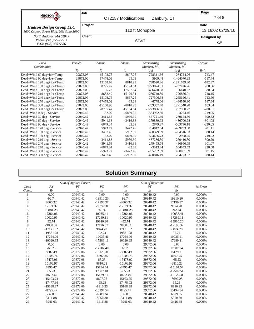
Tower Mast Reaction Summary
Load
Combination
Vertical
lb
Shearx
lb
Shearz
lb
Overturning
Moment, Mx lb-ft
Overturning
Moment, Mz lb-ft
Torque
lb-ft
Dead Only 20940.42 0.00 0.00 -201.98 118.75 0.00
Dead+Wind 0 deg - No Ice 20940.42 -92.74 -19910.20 -1629255.16 9051.90 -626.10
Dead+Wind 30 deg - No Ice 20940.42 9860.32 -17196.37 -1406565.56 -805557.28 -856.53 Dead+Wind 60 deg - No Ice 20940.42 17171.32 -9874.78 -807011.95 -1404285.32 -857.29
Dead+Wind 90 deg - No Ice 20940.42 19881.28 92.74 8722.92 -1626669.18 -628.27
Dead+Wind 120 deg - No Ice 20940.42 17264.06 10035.41 822028.43 -1413154.99 -231.11 Dead+Wind 150 deg - No Ice 20940.42 10020.95 17289.11 1415013.59 -820989.96 227.78
Dead+Wind 180 deg - No Ice 20940.42 92.74 19910.20 1628826.35 -8811.94 625.80
Dead+Wind 210 deg - No Ice 20940.42 -9860.32 17196.37 1406144.83 805795.88 856.35 Dead+Wind 240 deg - No Ice 20940.42 -17171.32 9874.78 806596.59 1404530.31 857.40
Dead+Wind 270 deg - No Ice 20940.42 -19881.28 -92.74 -9140.99 1626921.90 628.58
Dead+Wind 300 deg - No Ice 20940.42 -17264.06 -10035.41 -822454.57 1413409.07 231.31 Dead+Wind 330 deg - No Ice 20940.42 -10020.95 -17289.11 -1415445.10 821237.65 -227.90
Dead+Ice+Temp 29872.06 -0.00 -0.00 -376.27 220.89 0.04
Dead+Wind 0 deg+Ice+Temp 29872.06 -65.23 -17507.54 -1467239.84 6606.80 -530.52 Dead+Wind 30 deg+Ice+Temp 29872.06 8682.49 -15129.31 -1267551.28 -726410.82 -718.26
Job
CT2157 Modifications Danbury, CT
Page
7 of 8
Hudson Design Group LLC
1600 Osgood Street Bldg. 20N Suite 3090
Project
110 ft Monopole
Date
13:16:02 02/29/16
North Andover, MA 01845
Phone: (978) 557-5553 FAX: (978) 336-5586
Client
AT&T Designed by
kw
Load Combination
Vertical
lb
Shearx
lb
Shearz
lb
Overturning Moment, Mx
lb-ft
Overturning Moment, Mz
lb-ft
Torque
lb-ft
Dead+Wind 60 deg+Ice+Temp 29872.06 15103.75 -8697.25 -728311.66 -1264724.26 -713.47 Dead+Wind 90 deg+Ice+Temp 29872.06 17478.02 65.23 5969.48 -1464070.25 -517.44
Dead+Wind 120 deg+Ice+Temp 29872.06 15168.98 8810.23 738520.36 -1271059.30 -182.87
Dead+Wind 150 deg+Ice+Temp 29872.06 8795.47 15194.54 1273074.31 -737426.26 200.56 Dead+Wind 180 deg+Ice+Temp 29872.06 65.23 17507.54 1466420.88 -6140.67 530.34
Dead+Wind 210 deg+Ice+Temp 29872.06 -8682.49 15129.31 1266740.80 726876.01 718.15
Dead+Wind 240 deg+Ice+Temp 29872.06 -15103.75 8697.25 727506.38 1265196.41 713.50 Dead+Wind 270 deg+Ice+Temp 29872.06 -17478.02 -65.23 -6778.06 1464550.30 517.64
Dead+Wind 300 deg+Ice+Temp 29872.06 -15168.98 -8810.23 -739337.40 1271540.28 183.04
Dead+Wind 330 deg+Ice+Temp 29872.06 -8795.47 -15194.54 -1273896.56 737900.27 -200.61 Dead+Wind 0 deg - Service 20940.42 -32.09 -6889.35 -564922.60 3224.46 -219.95
Dead+Wind 30 deg - Service 20940.42 3411.88 -5950.30 -487721.39 -279154.86 -300.82
Dead+Wind 60 deg - Service 20940.42 5941.63 -3416.88 -279889.92 -486700.28 -301.08 Dead+Wind 90 deg - Service 20940.42 6879.34 32.09 2879.27 -563796.18 -220.65
Dead+Wind 120 deg - Service 20940.42 5973.72 3472.46 284817.04 -489793.88 -81.11
Dead+Wind 150 deg - Service 20940.42 3467.46 5982.39 490379.99 -284516.33 80.14 Dead+Wind 180 deg - Service 20940.42 32.09 6889.35 564486.73 -2968.65 219.92
Dead+Wind 210 deg - Service 20940.42 -3411.88 5950.30 487286.50 279410.50 300.79
Dead+Wind 240 deg - Service 20940.42 -5941.63 3416.88 279455.68 486956.69 301.07 Dead+Wind 270 deg - Service 20940.42 -6879.34 -32.09 -3313.84 564053.53 220.68
Dead+Wind 300 deg - Service 20940.42 -5973.72 -3472.46 -285252.59 490051.39 81.15
Dead+Wind 330 deg - Service 20940.42 -3467.46 -5982.39 -490816.19 284773.07 -80.14
Solution Summary
Load
Comb.
Sum of Applied Forces Sum of Reactions % Error PX
lb
PY
lb
PZ
lb
PX
lb
PY
lb
PZ
lb
1 0.00 -20940.42 0.00 0.00 20940.42 0.00 0.000%
2 -92.74 -20940.42 -19910.20 92.74 20940.42 19910.20 0.000% 3 9860.32 -20940.42 -17196.37 -9860.32 20940.42 17196.37 0.000%
4 17171.32 -20940.42 -9874.78 -17171.32 20940.42 9874.78 0.000%
5 19881.28 -20940.42 92.74 -19881.28 20940.42 -92.74 0.000% 6 17264.06 -20940.42 10035.41 -17264.06 20940.42 -10035.41 0.000%
7 10020.95 -20940.42 17289.11 -10020.95 20940.42 -17289.11 0.000%
8 92.74 -20940.42 19910.20 -92.74 20940.42 -19910.20 0.000% 9 -9860.32 -20940.42 17196.37 9860.32 20940.42 -17196.37 0.000%
10 -17171.32 -20940.42 9874.78 17171.32 20940.42 -9874.78 0.000%
11 -19881.28 -20940.42 -92.74 19881.28 20940.42 92.74 0.000% 12 -17264.06 -20940.42 -10035.41 17264.06 20940.42 10035.41 0.000%
13 -10020.95 -20940.42 -17289.11 10020.95 20940.42 17289.11 0.000%
14 0.00 -29872.06 0.00 0.00 29872.06 0.00 0.000% 15 -65.23 -29872.06 -17507.48 65.23 29872.06 17507.54 0.000%
16 8682.49 -29872.06 -15129.31 -8682.49 29872.06 15129.31 0.000%
17 15103.74 -29872.06 -8697.25 -15103.75 29872.06 8697.25 0.000% 18 17477.96 -29872.06 65.23 -17478.02 29872.06 -65.23 0.000%
19 15168.97 -29872.06 8810.23 -15168.98 29872.06 -8810.23 0.000%
20 8795.47 -29872.06 15194.54 -8795.47 29872.06 -15194.54 0.000% 21 65.23 -29872.06 17507.48 -65.23 29872.06 -17507.54 0.000%
22 -8682.49 -29872.06 15129.31 8682.49 29872.06 -15129.31 0.000%
23 -15103.74 -29872.06 8697.25 15103.75 29872.06 -8697.25 0.000% 24 -17477.96 -29872.06 -65.23 17478.02 29872.06 65.23 0.000%
25 -15168.97 -29872.06 -8810.23 15168.98 29872.06 8810.23 0.000%
26 -8795.47 -29872.06 -15194.54 8795.47 29872.06 15194.54 0.000% 27 -32.09 -20940.42 -6889.34 32.09 20940.42 6889.35 0.000%
28 3411.88 -20940.42 -5950.30 -3411.88 20940.42 5950.30 0.000%
29 5941.63 -20940.42 -3416.88 -5941.63 20940.42 3416.88 0.000%

Job
CT2157 Modifications Danbury, CT
Page
8 of 8
Hudson Design Group LLC
1600 Osgood Street Bldg. 20N Suite 3090
Project
110 ft Monopole
Date
13:16:02 02/29/16
North Andover, MA 01845
Phone: (978) 557-5553 FAX: (978) 336-5586
Client
AT&T Designed by
kw
Load
Comb.
Sum of Applied Forces Sum of Reactions % Error PX
lb
PY
lb
PZ
lb
PX
lb
PY
lb
PZ
lb
30 6879.33 -20940.42 32.09 -6879.34 20940.42 -32.09 0.000% 31 5973.72 -20940.42 3472.46 -5973.72 20940.42 -3472.46 0.000%
32 3467.46 -20940.42 5982.39 -3467.46 20940.42 -5982.39 0.000%
33 32.09 -20940.42 6889.34 -32.09 20940.42 -6889.35 0.000% 34 -3411.88 -20940.42 5950.30 3411.88 20940.42 -5950.30 0.000%
35 -5941.63 -20940.42 3416.88 5941.63 20940.42 -3416.88 0.000%
36 -6879.33 -20940.42 -32.09 6879.34 20940.42 32.09 0.000% 37 -5973.72 -20940.42 -3472.46 5973.72 20940.42 3472.46 0.000%
38 -3467.46 -20940.42 -5982.39 3467.46 20940.42 5982.39 0.000%
Maximum Tower Deflections - Service Wind
Section
No.
Elevation
ft
Horz.
Deflection in
Gov.
Load Comb.
Tilt
°
Twist
°
L1 111 - 97.5 29.7008 38 2.2928 0.0070
L2 97.5 - 97 23.2379 38 2.2679 0.0064
L3 97 - 72 23.0006 38 2.2653 0.0063 L4 72 - 47 12.2455 38 1.7394 0.0025
L5 51 - 21 5.9005 38 1.1346 0.0012
L6 21 - 1 0.8973 38 0.4312 0.0003
Critical Deflections and Radius of Curvature - Service Wind
Elevation
ft
Appurtenance Gov.
Load
Comb.
Deflection
in
Tilt
°
Twist
°
Radius of
Curvature
ft
108.00 2' Standoff T-Arm (10' face width) 38 28.2590 2.2916 0.0071 37000 100.00 Powerwave 7770 w/mount pipe 38 24.4274 2.2782 0.0068 14596
99.00 PiROD 13' Platform w/handrail 38 23.9510 2.2745 0.0067 11842
90.00 PiROD 13' Platform w/handrail 38 19.7396 2.1860 0.0051 3688
Section Capacity Table
Section
No.
Elevation
ft
Component
Type
Size Critical
Element
P
lb
SF*Pallow
lb
%
Capacity
Pass
Fail
L1 111 - 97.5 Pole TP16x16x0.375 1 -4051.99 530011.44 20.4 Pass
L2 97.5 - 97 Pole TP17.49x16x0.375 2 -4053.67 530011.44 20.4 Pass L3 97 - 72 Pole TP22.735x17.49x0.25 3 -8852.60 927544.02 85.8 Pass
L4 72 - 47 Pole TP27.98x22.735x0.3 4 -11759.90 1328674.36 97.2 Pass
L5 47 - 21 Pole TP33.392x26.5408x0.365 5 -17385.90 1989129.18 93.4 Pass L6 21 - 1 Pole TP37x33.392x0.389 6 -20929.80 2349972.26 93.6 Pass
Summary
Pole (L4) 97.2 Pass RATING = 97.2 Pass

TIA Rev FSite Data Reactions
BU#: Moment: 900 ft-kips
Site Name: Axial: 14 kips
App #: Shear: 14 kips
Other
If No stiffeners, Criteria: AISC ASD <-Only Applcable to Unstiffened Cases
Qty: 8
Diam: 2.25 in
Rod Material: A615-J Anchor Rod Results Non-Rigid
Strength (Fu): 100 ksi Maximum Rod Tension: 118.3 Kips Service, ASD
Yield (Fy): 75 ksi Allowable Tension: 195.0 Kips Fty*ASIF
Bolt Circle: 45 in Anchor Rod Stress Ratio: 60.7% Pass
Diam: 51 in Base Plate Results Flexural Check Non-Rigid
Thick: 1.5 in Base Plate Stress: 53.6 ksi Service ASD
Grade: 60 ksi Allowable Plate Stress: 60.0 ksi 0.75*Fy*ASIF
Single-Rod B-eff: 14.68 in Base Plate Stress Ratio: 89.4% Pass Y.L. Length:
25.61
n/a
Config: 0 * Stiffener Results
Weld Type: Fillet Horizontal Weld : n/a
Groove Depth: 0.25 <-- Disregard Vertical Weld: n/a
Groove Angle: 45 <-- Disregard Plate Flex+Shear, fb/Fb+(fv/Fv)^2: n/a
Fillet H. Weld: 0.3125 in Plate Tension+Shear, ft/Ft+(fv/Fv)^2: n/a
Fillet V. Weld: 0.3125 in Plate Comp. (AISC Bracket): n/a
Width: 3 in n/a
Height: 18 in Pole Results
Thick: 0.75 in Pole Punching Shear Check: n/a
Notch: 0.5 in
Grade: 36 ksi
Weld str.: 70 ksi
Diam: 37 in
Thick: 0.389 in
Grade: 65 ksi
# of Sides: 18 "0" IF Round
Fu 80 ksi
Reinf. Fillet Weld 0 "0" if None
ASIF: 1.333
* 0 = none, 1 = every bolt, 2 = every 2 bolts, 3 = 2 per bolt
** Note: for complete joint penetration groove welds the groove depth must be exactly 1/2 the stiffener thickness for calculation purposes
4 in
Pole Manufacturer:
Stiffened or Unstiffened, Ungrouted, Circular Base Plate - Any Rod Material
Stress Increase Factor
0
Pole Data
Anchor Rod Data
Plate Data
Stiffener Data (Welding at both sides)
CT2157 Modifications
0
Clear Space between
Stiffeners (b):
CCIplate v2.0 Analysis Date: 2/28/2016
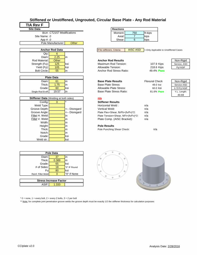
TIA Rev FSite Data Reactions
BU#: Moment: 750 ft-kips
Site Name: Axial: 7 kips
App #: Shear: 6 kips
Other
If No stiffeners, Criteria: AISC ASD <-Only Applcable to Unstiffened Cases
Qty: 6
Diam: 2.25 in
Rod Material: Other Anchor Rod Results Non-Rigid
Strength (Fu): 125 ksi Maximum Rod Tension: 107.9 Kips Service, ASD
Yield (Fy): 105 ksi Allowable Tension: 218.6 Kips Fty*ASIF
Bolt Circle: 55 in Anchor Rod Stress Ratio: 49.4% Pass
Diam: 61 in Base Plate Results Flexural Check Non-Rigid
Thick: 1.75 in Base Plate Stress: 49.0 ksi Service ASD
Grade: 60 ksi Allowable Plate Stress: 60.0 ksi 0.75*Fy*ASIF
Single-Rod B-eff: 19.57 in Base Plate Stress Ratio: 81.6% Pass Y.L. Length:
40.69
n/a
Config: 0 * Stiffener Results
Weld Type: Fillet Horizontal Weld : n/a
Groove Depth: 0.25 <-- Disregard Vertical Weld: n/a
Groove Angle: 45 <-- Disregard Plate Flex+Shear, fb/Fb+(fv/Fv)^2: n/a
Fillet H. Weld: 0.3125 in Plate Tension+Shear, ft/Ft+(fv/Fv)^2: n/a
Fillet V. Weld: 0.3125 in Plate Comp. (AISC Bracket): n/a
Width: 3 in n/a
Height: 18 in Pole Results
Thick: 0.75 in Pole Punching Shear Check: n/a
Notch: 0.5 in
Grade: 36 ksi
Weld str.: 70 ksi
Diam: 37 in
Thick: 0.389 in
Grade: 65 ksi
# of Sides: 18 "0" IF Round
Fu 80 ksi
Reinf. Fillet Weld 0 "0" if None
ASIF: 1.333
* 0 = none, 1 = every bolt, 2 = every 2 bolts, 3 = 2 per bolt
** Note: for complete joint penetration groove welds the groove depth must be exactly 1/2 the stiffener thickness for calculation purposes
4 in
Pole Manufacturer:
Stiffened or Unstiffened, Ungrouted, Circular Base Plate - Any Rod Material
Stress Increase Factor
0
Pole Data
Anchor Rod Data
Plate Data
Stiffener Data (Welding at both sides)
CT2157 Modifications
0
Clear Space between
Stiffeners (b):
CCIplate v2.0 Analysis Date: 2/28/2016

CCI Foundation Tool Suite - Monopole Pier
CCIFTS 1.1.103.14128 - Phase 1 Date: 2/28/2016
BU: CT2157
Site Name:
App Number: N/A
Work Order:
Monopole Drilled Pier
InputCriteria
TIA Revision: F
ACI 318 Revision: 2002
Seismic Category: B
ForcesCompression 21 kips
Shear 20 kips
Moment 1636 k-ft
Swelling Force 0 kips
Foundation Dimensions
Pier Diameter: 5.5 ft
Ext. above grade: 1 ft
Depth below grade: 20 ft
Material Properties
Number of Rebar: 24
Rebar Size: 8
Tie Size 4
Rebar tensile strength: 60 ksi
Concrete Strength: 3000 psi
Ultimate Concrete Strain 0.003 in/in
Clear Cover to Ties: 3 in
Soil Profile: Profile 1
Layer
Thickness
(ft)
From
(ft)
To
(ft)
Unit Weight
(pcf)
Cohesion
(psf)
Friction
Angle
(deg)
Ultimate
Uplift Skin
Friction
(ksf)
Ultimate
Comp. Skin
Friction
(ksf)
Ultimate
Bearing
Capacity
(ksf)
SPT 'N'
Counts
1 3 0 3 120 0 28
2 10 3 13 78 0 38
3 16 13 29 43 0 38
Analysis ResultsConcrete/Steel Check
Soil Lateral Capacity Mu (from soil analysis) 2250.67 k-ft
Depth to Zero Shear: 3.37 ft φMn 2367.71 k-ft
Max Moment, Mu: 1731.29 k-ft RATING: 95.1%
Soil Safety Factor: 2.56Safety Factor Req'd: 2
RATING: 78.1% rho provided 0.55
rho required 0.33 OK
Soil Axial Capacity
Skin Friction (k): 79.86 kips Rebar Spacing 6.59
End Bearing (k): 0.00 kips Spacing required 16.00 OKComp. Capacity (k), φCn: 79.86 kips
Comp. (k), Cu: 27.30 kips
RATING: 34.2% Dev. Length required 16.38
Dev. Length provided 43.82 OK
Overall Foundation Rating: 95.1%
(24) - #8
#4 Tie Size
21
'
20
'1
'
5.5'
3" C.C.
Page 1 of 1