wpca/firstenergy biomass seminarwpca.info/pdf/presentations/akron2009/stock_equipment.pdf ·...
TRANSCRIPT
WPCA/FirstEnergyBiomass Seminar
Akron, OhioDecember 3, 2009
All presentations posted on this website are copyrighted by the Worldwide PollutionControl Association (WPCA). Any unauthorized downloading, attempts to modify or toincorporate into other presentations, link to other websites, or obtain copies for anyother uses than the training of attendees to WPCA Conferences is expressively prohib-ited, unless approved in writing by the WPCA or the original presenter. The WPCAdoes not assume any liability for the accuracy or contents of any materials containedin this library which were presented and/or created by persons who were not employ-ees of the WPCA.
©S
chen
ck P
roce
ss20
09M
anag
emen
t Mee
ting
2009
Schenck Process weighing feeding screening automation conveying
Handling Biomass and Solid Alternative Fuels Simon ShippDecember 3rd 2009
WPCA / First Energy Biomass Seminar
©S
chen
ck P
roce
ss 2
009
Man
agem
ent M
eetin
g 20
09S
lide
No
2
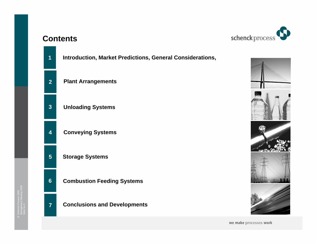
Contents
1
2
5
Introduction, Market Predictions, General Considerations,
Plant Arrangements
3
Conveying Systems
Unloading Systems
4
Storage Systems
6 Combustion Feeding Systems
7 Conclusions and Developments

©S
chen
ck P
roce
ss 2
009
Man
agem
ent M
eetin
g 20
09S
lide
No
3
1 Introduction, Market Predictions, General Considerations

©S
chen
ck P
roce
ss 2
009
Man
agem
ent M
eetin
g 20
09S
lide
No
4
Some Market Predictions
US investment in biomass power generation was at $0.4 billion in 2008, grew by $0.1bn 2007 - 2008. Currently remains the lowest clean energy investment level compared to wind at $17.7 billion.
Biomass powers attraction predicted to rise as the deficiencies and practical limits of solar and wind are revealed and policy change favors lower carbon thermal generation options.
• Investor interest is remerging, climate change legislation could incentivize investors further
• Fuel supply challenges present some practical hurdles
• Fossil fuel stability and volatility cycle may assist
• New conversion technologies make process efficiency gains that increase investment viability
• Biomass better suited to small scale, does not always scale up well for large wholesale power market
• Economics work well in CHP projects

©S
chen
ck P
roce
ss 2
009
Man
agem
ent M
eetin
g 20
09S
lide
No
5
got biomass?
©S
chen
ck P
roce
ss 2
009
Man
agem
ent M
eetin
g 20
09S
lide
No
6
©S
tock
Fai
rfiel
d, S
chen
ck P
roce
ss G
roup
200
8V
ersi
on A
1.0
Slid
e N
o 6
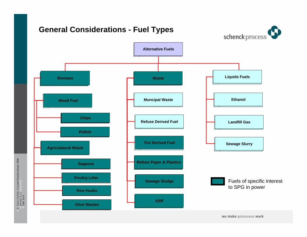
Biomass
Wood Fuel
Waste
Alternative Fuels
Agriculatural Waste
Chips
Liquids Fuels
Muncipal Waste
Refuse Derived Fuel
Tire Derived Fuel
Sewage Sludge
Refuse Paper & Plastics
Ethanol
Landfill Gas
Sewage Slurry
Pellets
Bagasse
Poultry Litter
Rice Husks
Olive Wastes
Fuels of specific interest to SPG in power
General Considerations - Fuel Types
ASR
©S
chen
ck P
roce
ss 2
009
Man
agem
ent M
eetin
g 20
09S
lide
No
7
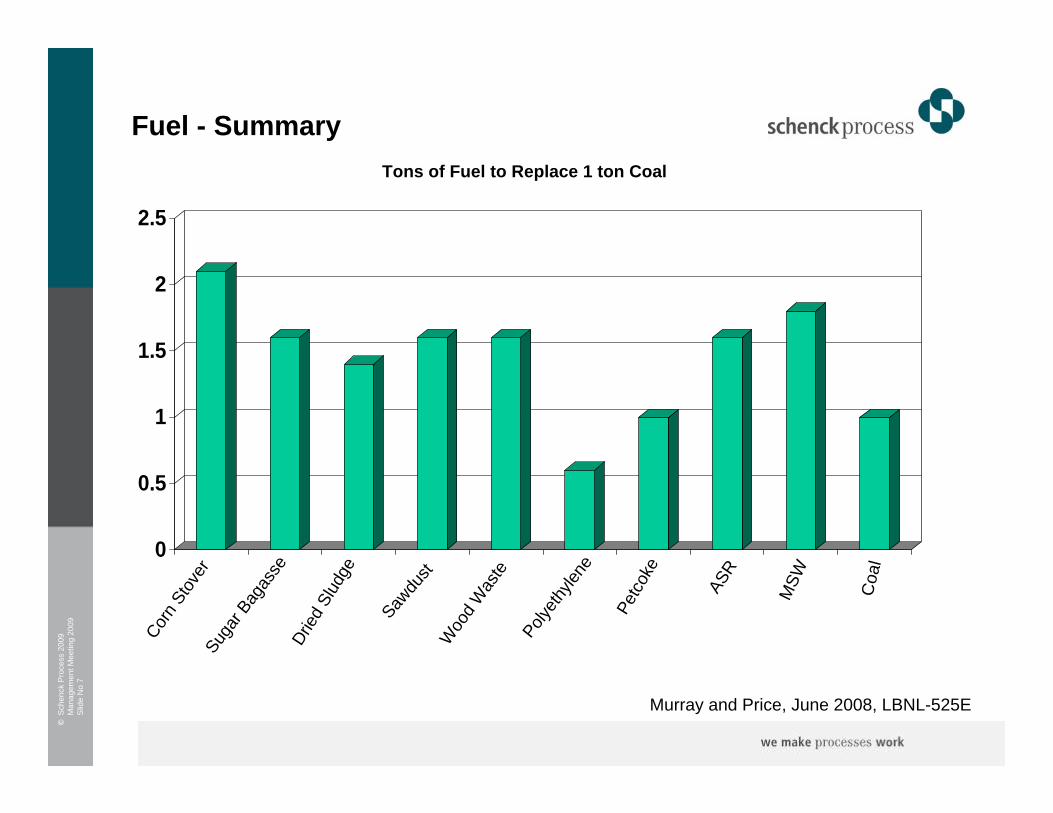
Fuel - SummaryTons of Fuel to Replace 1 ton Coal
0
0.5
1
1.5
2
2.5
Murray and Price, June 2008, LBNL-525E
Corn
Stov
erSu
gar B
agas
seDr
ied S
ludge
Sawdu
stW
ood W
aste
Polyeth
ylene
Petco
ke
ASR
MSW Coa
l
©S
chen
ck P
roce
ss 2
009
Man
agem
ent M
eetin
g 20
09S
lide
No
8
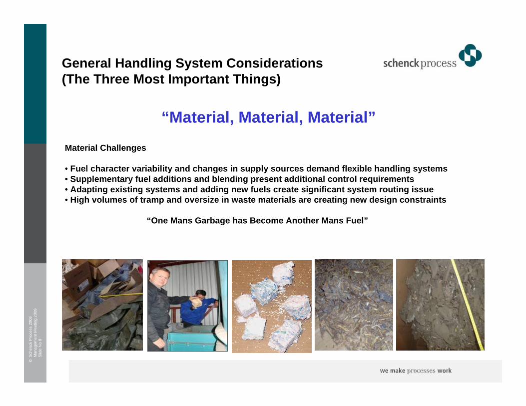
General Handling System Considerations (The Three Most Important Things)
Material Challenges
• Fuel character variability and changes in supply sources demand flexible handling systems• Supplementary fuel additions and blending present additional control requirements• Adapting existing systems and adding new fuels create significant system routing issue• High volumes of tramp and oversize in waste materials are creating new design constraints
“One Mans Garbage has Become Another Mans Fuel”
“Material, Material, Material”
©S
chen
ck P
roce
ss 2
009
Man
agem
ent M
eetin
g 20
09S
lide
No
9
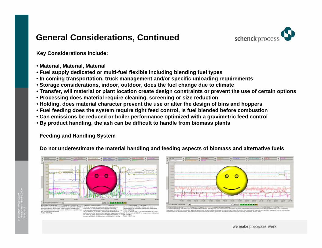
General Considerations, ContinuedKey Considerations Include:
• Material, Material, Material • Fuel supply dedicated or multi-fuel flexible including blending fuel types• In coming transportation, truck management and/or specific unloading requirements • Storage considerations, indoor, outdoor, does the fuel change due to climate• Transfer, will material or plant location create design constraints or prevent the use of certain options• Processing does material require cleaning, screening or size reduction• Holding, does material character prevent the use or alter the design of bins and hoppers• Fuel feeding does the system require tight feed control, is fuel blended before combustion• Can emissions be reduced or boiler performance optimized with a gravimetric feed control• By product handling, the ash can be difficult to handle from biomass plants
Feeding and Handling System
Do not underestimate the material handling and feeding aspects of biomass and alternative fuels

©S
chen
ck P
roce
ss 2
009
Man
agem
ent M
eetin
g 20
09S
lide
No
10
4 Plant Arrangements
©S
chen
ck P
roce
ss 2
009
Man
agem
ent M
eetin
g 20
09S
lide
No
11
Plant Arrangements
We typically look at three general handling arrangement types:
Arrangement One, Dedicated Biomass System Conversion or New Build
Complete system from intake to Boiler. 200mw or less normally. Typical plant size of 50mw. Road truck unloading , occasionally rail transport. Covered storage with automated reclaim. Boiler feeding is volumetric or potentially gravimetric
Arrangement Two, Supplementary Fuel Addition
Addition of a defined % of new fuel onto the existing intake and handling system. Fuel is normally added before the local boiler storage bunker. The addition is most likely as a volumetric feed.
Arrangement Three, New Fuel Addition
The installation of a complete and separate system to handle the wholly new fuel. Can be prior to existing combustion process or as a stand alone feeding system. Gravimetric or volumetric control.
©S
chen
ck P
roce
ss 2
009
Man
agem
ent M
eetin
g 20
09S
lide
No
12
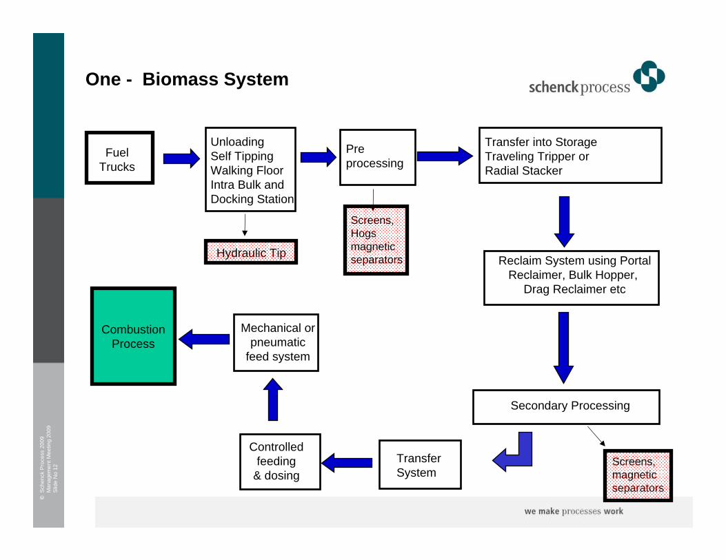
Controlledfeeding
& dosing
Unloading Self TippingWalking FloorIntra Bulk andDocking Station
Pre processing
Mechanical or pneumatic
feed system
Screens, Hogs magnetic separators
One - Biomass System
FuelTrucks
Hydraulic Tip
Transfer into StorageTraveling Tripper or Radial Stacker
Reclaim System using PortalReclaimer, Bulk Hopper,
Drag Reclaimer etc
Secondary Processing
Screens, magnetic separators
Transfer System
CombustionProcess

©S
chen
ck P
roce
ss 2
009
Man
agem
ent M
eetin
g 20
09S
lide
No
13
Controlledfeeding
& dosing
Two - Supplementary Biomass Fuel Addition
Coal Rail or Road
Stockpile Radial Stacker
Unloading, Transferto Pile
Reclaim System
Secondary Processing
Transfer System
CombustionProcess
Biomass Trucks
Unloading System Fueldependent
Storage Pile Tripperor Stacker
ReclaimSystem
Live StorageAt
Plant
Feeder FeederElemental Analysis

©S
chen
ck P
roce
ss 2
009
Man
agem
ent M
eetin
g 20
09S
lide
No
14
Unloading Self TippingWalking FloorIntra Bulk andDocking Station
Processing
Mechanical or PneumaticControlled
Feed system
Just in time feeding?
Screens, Hogs magnetic separators
Three – Stand Alone Biomass Fuel Addition
FuelTrucks
Hydraulic Tip
CombustionProcess
Transfer to Storage
Reclaim and Transfer
Gravimetric Feeding

©S
chen
ck P
roce
ss 2
009
Man
agem
ent M
eetin
g 20
09S
lide
No
15
3 Unloading Systems
©S
chen
ck P
roce
ss 2
009
Man
agem
ent M
eetin
g 20
09S
lide
No
16
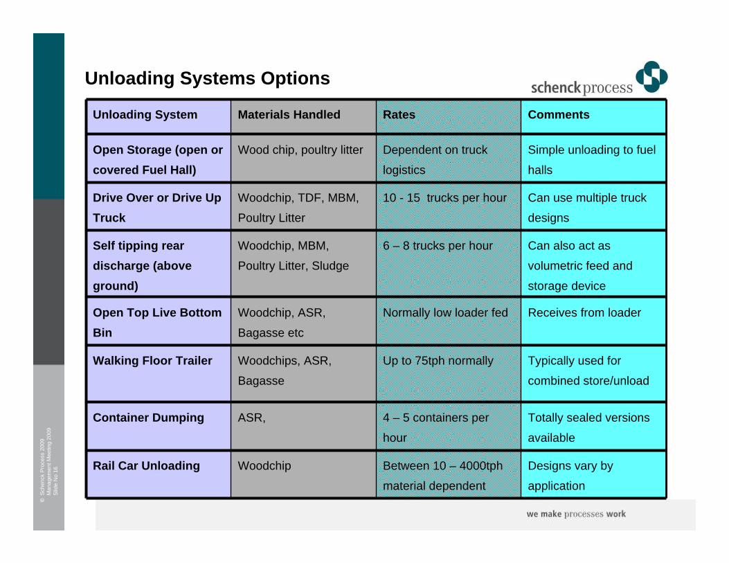
Unloading Systems Options
Receives from loaderNormally low loader fedWoodchip, ASR,
Bagasse etc
Open Top Live Bottom Bin
Simple unloading to fuel
halls
Dependent on truck
logistics
Wood chip, poultry litterOpen Storage (open or covered Fuel Hall)
Designs vary by
application
Between 10 – 4000tph
material dependent
WoodchipRail Car Unloading
Totally sealed versions
available
4 – 5 containers per
hour
ASR, Container Dumping
Typically used for
combined store/unload
Up to 75tph normally Woodchips, ASR,
Bagasse
Walking Floor Trailer
Can also act as
volumetric feed and
storage device
6 – 8 trucks per hourWoodchip, MBM,
Poultry Litter, Sludge
Self tipping rear discharge (above ground)
Can use multiple truck
designs
10 - 15 trucks per hour Woodchip, TDF, MBM,
Poultry Litter
Drive Over or Drive Up Truck
CommentsRatesMaterials Handled Unloading System
©S
chen
ck P
roce
ss 2
009
Man
agem
ent M
eetin
g 20
09S
lide
No
17
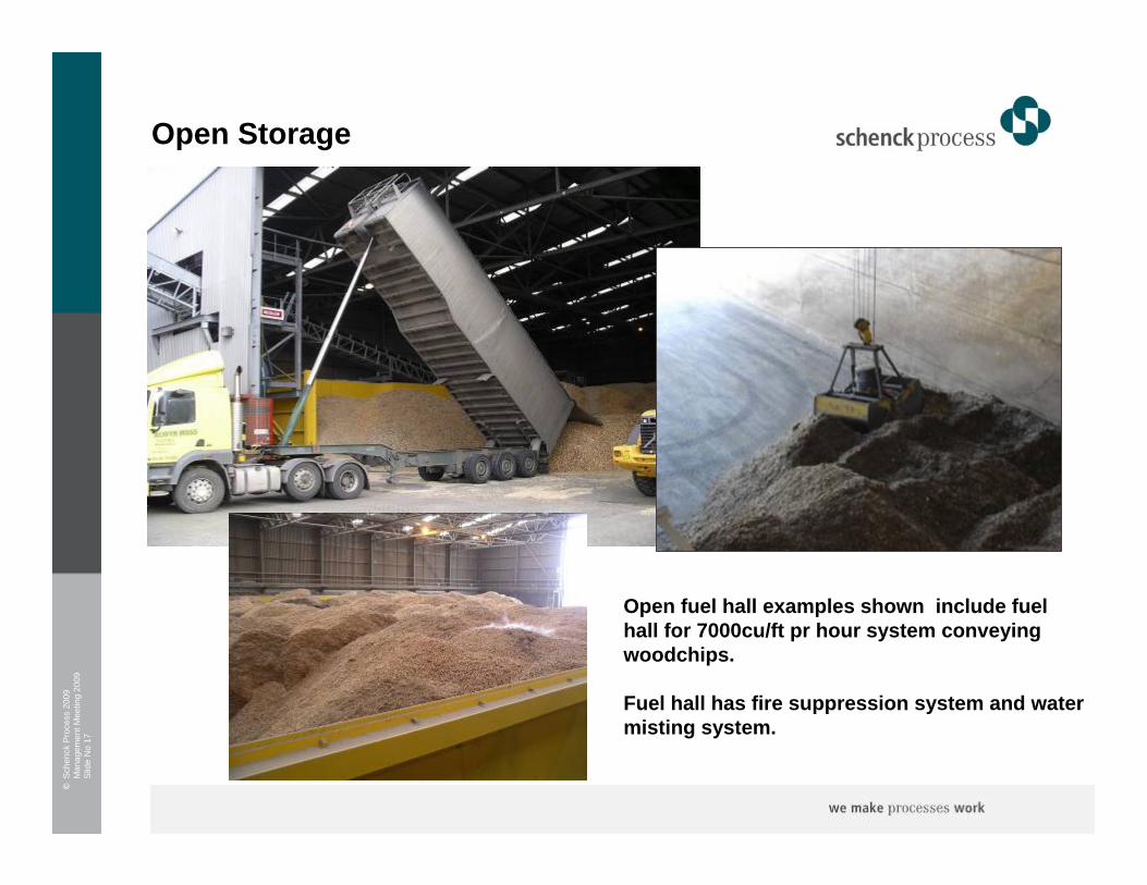
Open Storage
Open fuel hall examples shown include fuel hall for 7000cu/ft pr hour system conveying woodchips.
Fuel hall has fire suppression system and water misting system.
©S
chen
ck P
roce
ss 2
009
Man
agem
ent M
eetin
g 20
09S
lide
No
18
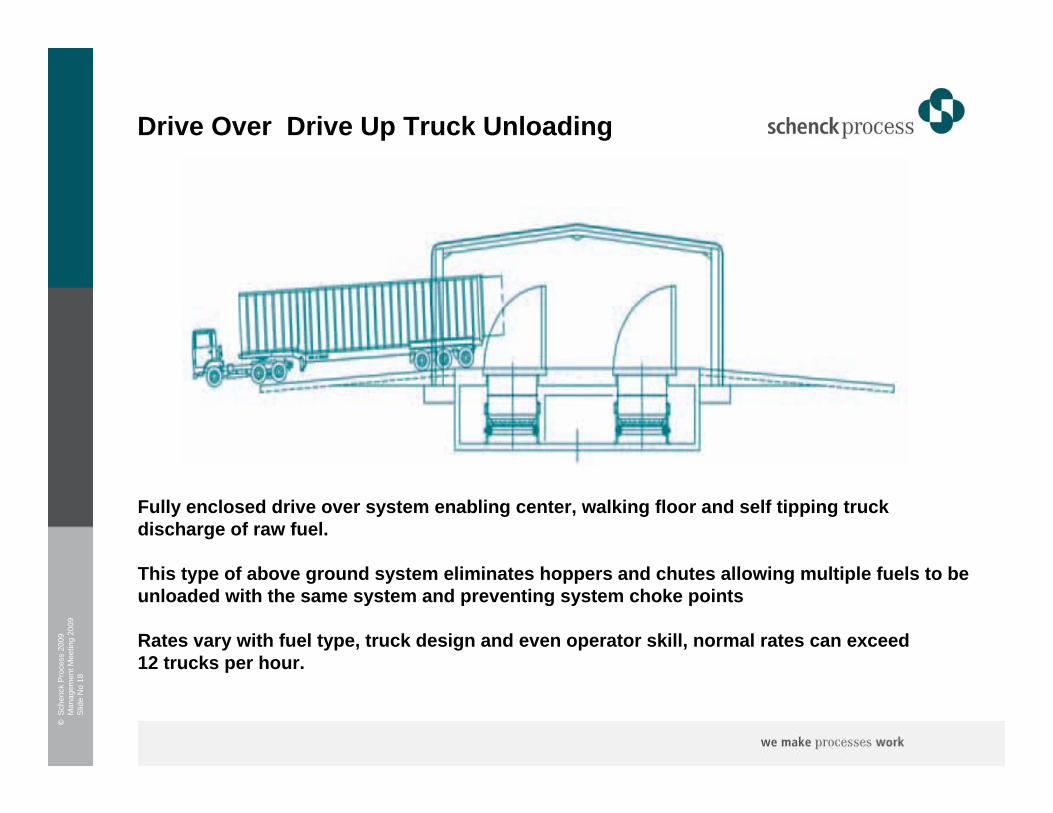
Drive Over Drive Up Truck Unloading
Fully enclosed drive over system enabling center, walking floor and self tipping truckdischarge of raw fuel.
This type of above ground system eliminates hoppers and chutes allowing multiple fuels to be unloaded with the same system and preventing system choke points
Rates vary with fuel type, truck design and even operator skill, normal rates can exceed 12 trucks per hour.
©S
chen
ck P
roce
ss 2
009
Man
agem
ent M
eetin
g 20
09S
lide
No
19
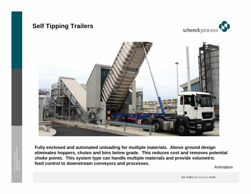
Self Tipping Trailers
Fully enclosed and automated unloading for multiple materials. Above ground design eliminates hoppers, chutes and bins below grade. This reduces cost and removes potential choke points. This system type can handle multiple materials and provide volumetricfeed control to downstream conveyors and processes.
Animation
©S
chen
ck P
roce
ss 2
009
Man
agem
ent M
eetin
g 20
09S
lide
No
20
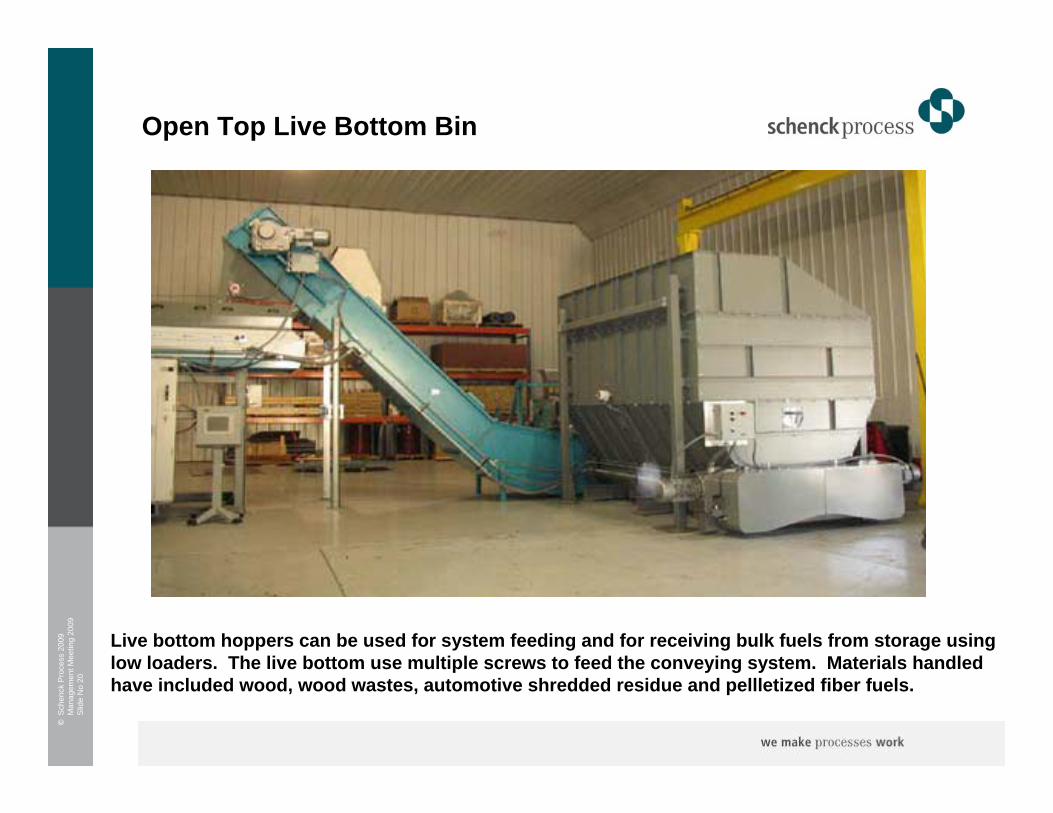
Open Top Live Bottom Bin
Live bottom hoppers can be used for system feeding and for receiving bulk fuels from storage usinglow loaders. The live bottom use multiple screws to feed the conveying system. Materials handled have included wood, wood wastes, automotive shredded residue and pellletized fiber fuels.

©S
chen
ck P
roce
ss 2
009
Man
agem
ent M
eetin
g 20
09S
lide
No
21
Walking Floor Trailers (Docking Station)
The station uses a neoprene buffer to createa soft seal around the trailer doors. This enables material from the trailer to fall into the live bottom hopper for accurate flow control to the storage or process system.

©S
chen
ck P
roce
ss 2
009
Man
agem
ent M
eetin
g 20
09S
lide
No
22
Container Dumping
Container placed within fully enclosed vented enclosure
Container Tipping System
©S
chen
ck P
roce
ss 2
009
Man
agem
ent M
eetin
g 20
09S
lide
No
23
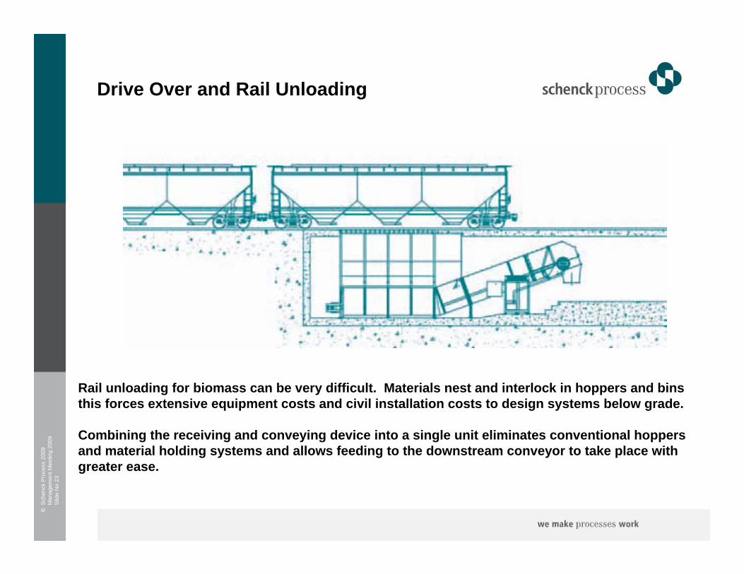
Drive Over and Rail Unloading
Rail unloading for biomass can be very difficult. Materials nest and interlock in hoppers and binsthis forces extensive equipment costs and civil installation costs to design systems below grade.
Combining the receiving and conveying device into a single unit eliminates conventional hoppers and material holding systems and allows feeding to the downstream conveyor to take place with greater ease.
©S
chen
ck P
roce
ss 2
009
Man
agem
ent M
eetin
g 20
09S
lide
No
24
4 Conveying
©S
chen
ck P
roce
ss 2
009
Man
agem
ent M
eetin
g 20
09S
lide
No
25
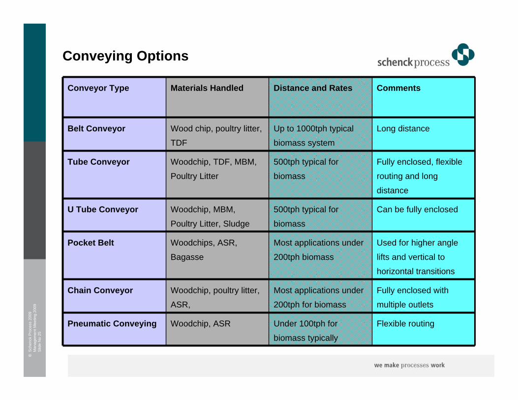
Conveying Options
Long distance Up to 1000tph typical
biomass system
Wood chip, poultry litter,
TDF
Belt Conveyor
Flexible routingUnder 100tph for
biomass typically
Woodchip, ASRPneumatic Conveying
Fully enclosed with
multiple outlets
Most applications under
200tph for biomass
Woodchip, poultry litter,
ASR,
Chain Conveyor
Used for higher angle
lifts and vertical to
horizontal transitions
Most applications under
200tph biomass
Woodchips, ASR,
Bagasse
Pocket Belt
Can be fully enclosed500tph typical for
biomass
Woodchip, MBM,
Poultry Litter, Sludge
U Tube Conveyor
Fully enclosed, flexible
routing and long
distance
500tph typical for
biomass
Woodchip, TDF, MBM,
Poultry Litter
Tube Conveyor
CommentsDistance and RatesMaterials Handled Conveyor Type
©S
chen
ck P
roce
ss 2
009
Man
agem
ent M
eetin
g 20
09S
lide
No
26
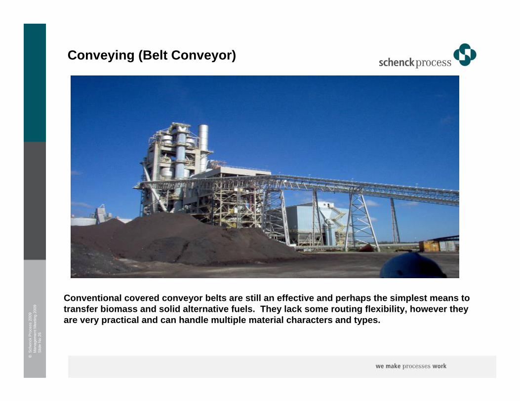
Conveying (Belt Conveyor)
Conventional covered conveyor belts are still an effective and perhaps the simplest means to transfer biomass and solid alternative fuels. They lack some routing flexibility, however they are very practical and can handle multiple material characters and types.
©S
chen
ck P
roce
ss 2
009
Man
agem
ent M
eetin
g 20
09S
lide
No
27
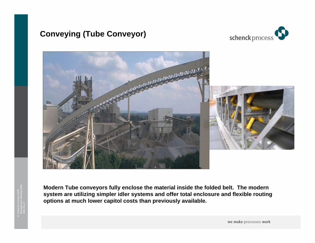
Conveying (Tube Conveyor)
Modern Tube conveyors fully enclose the material inside the folded belt. The modern system are utilizing simpler idler systems and offer total enclosure and flexible routing options at much lower capitol costs than previously available.

©S
chen
ck P
roce
ss 2
009
Man
agem
ent M
eetin
g 20
09S
lide
No
28
Conveying (U Conveyor)
The U conveyor creates a trough reducing dusting and spillage and providing far greater materialcontrol than a conventional belt.
The systems are typically used in conjunction withfull system enclosure when environmentalbarriers are a must.
©S
chen
ck P
roce
ss 2
009
Man
agem
ent M
eetin
g 20
09S
lide
No
29
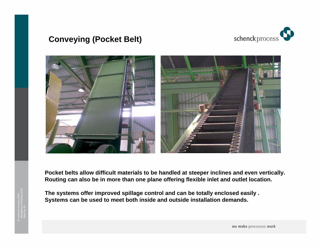
Conveying (Pocket Belt)
Pocket belts allow difficult materials to be handled at steeper inclines and even vertically. Routing can also be in more than one plane offering flexible inlet and outlet location.
The systems offer improved spillage control and can be totally enclosed easily . Systems can be used to meet both inside and outside installation demands.
©S
chen
ck P
roce
ss 2
009
Man
agem
ent M
eetin
g 20
09S
lide
No
30
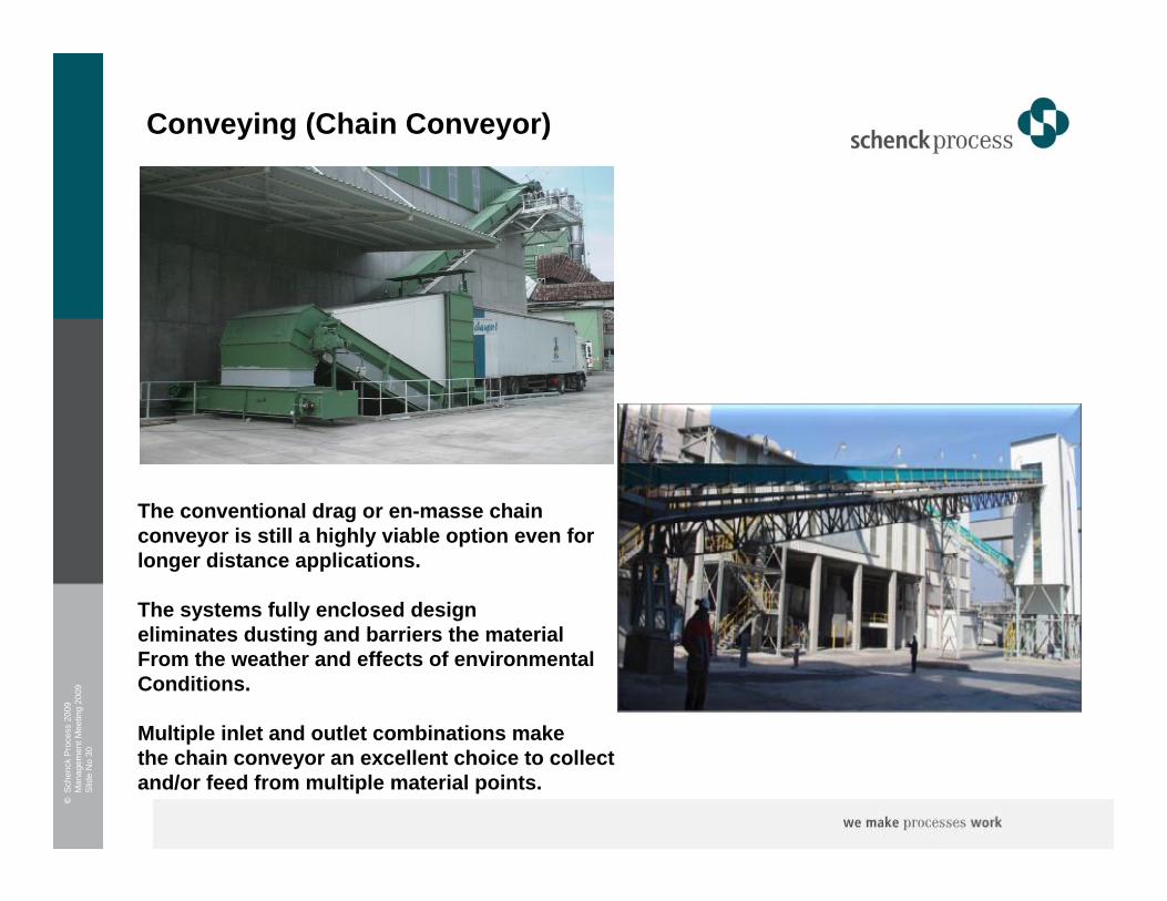
Conveying (Chain Conveyor)
The conventional drag or en-masse chainconveyor is still a highly viable option even forlonger distance applications.
The systems fully enclosed design eliminates dusting and barriers the materialFrom the weather and effects of environmental Conditions.
Multiple inlet and outlet combinations makethe chain conveyor an excellent choice to collectand/or feed from multiple material points.

©S
chen
ck P
roce
ss 2
009
Man
agem
ent M
eetin
g 20
09S
lide
No
31
Conveying (Pneumatic Conveyor)
The use of dilute phase conveying will grow due to the success seen handling solid alternative fuels and biomass in cement kiln Applications.
The systems are able to better handle the biomass material characters and offer a fullyenclosed and flexible routing option for certain material characters. The latest generation of feeders are radically lower in maintenancerequirement.
Normal operating range is up to 7000 cu/ft per hour with a 45 lbs/cuft material with a 1.5 inch maximum particle size.

©S
chen
ck P
roce
ss 2
009
Man
agem
ent M
eetin
g 20
09S
lide
No
32
Conveying (Screw Conveyor)
Sometime the screw conveyor can be the best way, despite some restrictions on certain fuels the screw has benefits providing a combined pre-feed and conveyor for shorter distance lower rate applications.

©S
chen
ck P
roce
ss 2
009
Man
agem
ent M
eetin
g 20
09S
lide
No
33
5 Storage

©S
chen
ck P
roce
ss 2
009
Man
agem
ent M
eetin
g 20
09S
lide
No
34
Storage Options
Use of bridge
conveyors is possible
Large covered capacity
used for fuels
adversely effected by
moisture
Wood chip, poultry
litter, TDF
Storage Hall
Normally created by
stacker
Outdoor fuel pileWoodchip, ASROpen Stockpiles
Volumetric control to
downstream process
Truck unloading and
process feed
Woodchip, poultry litter,
ASR,
Integrated receiving and Storage Systems
Integrated trailer
hydraulic system
Can be used to store
and feed material
Woodchips, ASR,
Bagasse
Walking Floors
Smaller local storageCombined feed and
storage device
Woodchip, MBM,
Poultry Litter, Sludge
Live Bottom Bins
Fully enclosed Enclosed storage Woodchip, TDF, MBM,
Poultry Litter
Silos
CommentsApplication Materials Handled Storage Type

©S
chen
ck P
roce
ss 2
009
Man
agem
ent M
eetin
g 20
09S
lide
No
35
Enclosed Storage – (Storage Hall)
Fully covered storage halls provide complete weather protection, but require extensive real estate and civilcosts. Filling the hall can be manual or fully automated using overhead bridge and pile reclaiming.
For some fuel types the reclaim is completed using grab cranes to reduce operator material contact for health and safety reasons.
©S
chen
ck P
roce
ss 2
009
Man
agem
ent M
eetin
g 20
09S
lide
No
36
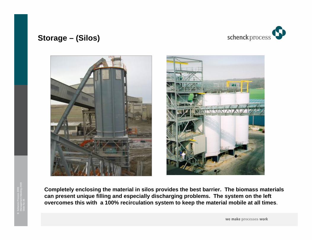
Storage – (Silos)
Completely enclosing the material in silos provides the best barrier. The biomass materials can present unique filling and especially discharging problems. The system on the left overcomes this with a 100% recirculation system to keep the material mobile at all times.
©S
chen
ck P
roce
ss 2
009
Man
agem
ent M
eetin
g 20
09S
lide
No
37
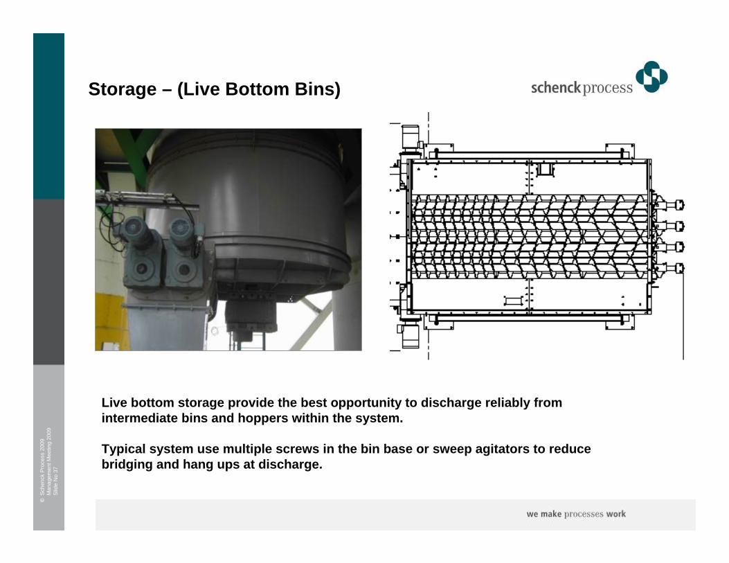
Storage – (Live Bottom Bins)
Live bottom storage provide the best opportunity to discharge reliably from intermediate bins and hoppers within the system.
Typical system use multiple screws in the bin base or sweep agitators to reduce bridging and hang ups at discharge.

©S
chen
ck P
roce
ss 2
009
Man
agem
ent M
eetin
g 20
09S
lide
No
38
Storage – (Walking Floors)
Hydraulic walking floors or ladder floors allow large volumes of material prone to discharge issue to be positively displaced onto the downstream conveying system. Although generallyreliable they can be less resilient to tramp material contained hidden within the stockpile.
©S
chen
ck P
roce
ss 2
009
Man
agem
ent M
eetin
g 20
09S
lide
No
39
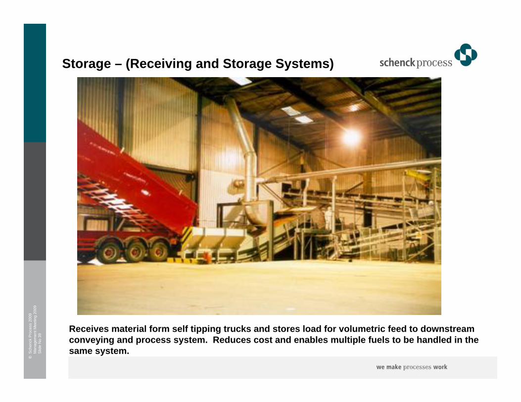
Storage – (Receiving and Storage Systems)
Receives material form self tipping trucks and stores load for volumetric feed to downstream conveying and process system. Reduces cost and enables multiple fuels to be handled in thesame system.
©S
chen
ck P
roce
ss 2
009
Man
agem
ent M
eetin
g 20
09S
lide
No
40
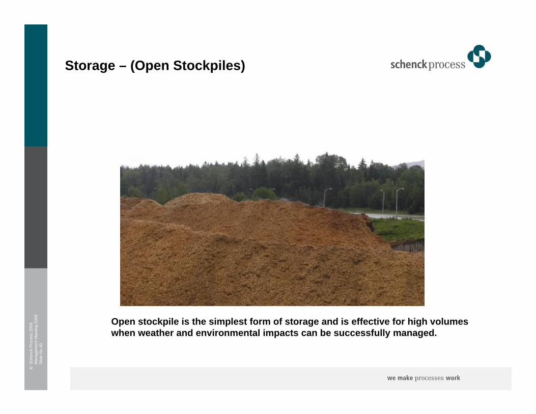
Storage – (Open Stockpiles)
Open stockpile is the simplest form of storage and is effective for high volumeswhen weather and environmental impacts can be successfully managed.

©S
chen
ck P
roce
ss 2
009
Man
agem
ent M
eetin
g 20
09S
lide
No
41
6 Combustion System Feeding

©S
chen
ck P
roce
ss 2
009
Man
agem
ent M
eetin
g 20
09S
lide
No
42
Boiler Feeding Systems
Standard feed
approach
Standard feeding
approach
Woodchip, ASR,
Bagasse etc
Screw
Specifically for
biomass
Wood chip, poultry
litter
Mechanical (Belt feeder)
Simple belt feederSimple volumetric
feeder
ASR, Belt
Typically ahead of
screw feeder
Used to deliver fuelWoodchips, ASR,
Bagasse
Chain Conveyor
Technology used
for kiln firing
Dilute phase
conveying to burner
Woodchip, MBM,
Poultry Litter,
Sludge
Pneumatic (Fed by screw or belt)
Fed by agitated
hopper
Specific biomass
design
Woodchip, TDF,
MBM, Poultry Litter
Mechanical (Screw)
CommentsApplication Materials Handled Feeding System
Gravimetric+/- 0.5%Material
dependent
Volumetric+/- 5%
Material Dependent
©S
chen
ck P
roce
ss 2
009
Man
agem
ent M
eetin
g 20
09S
lide
No
43
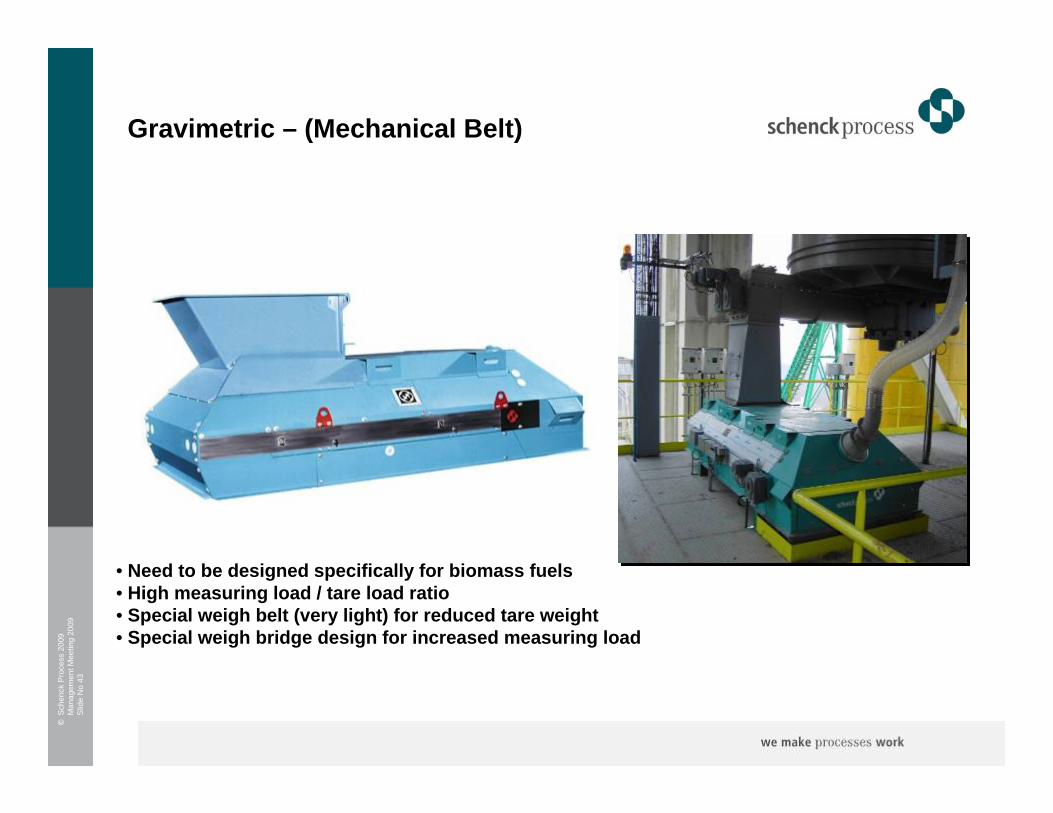
Gravimetric – (Mechanical Belt)
• Need to be designed specifically for biomass fuels• High measuring load / tare load ratio• Special weigh belt (very light) for reduced tare weight• Special weigh bridge design for increased measuring load

©S
chen
ck P
roce
ss 2
009
Man
agem
ent M
eetin
g 20
09S
lide
No
44
Gravimetric – (Mechanical Screw)
The system weighs the bin and screw at twopoints to determine a gravimetric feed rate at of +/- 0.5%*
The system successfully handles the variation of bulk density seen in biomass fuels.
* Accuracy depends on bulk density and material character
MultiFlexVideo
©S
chen
ck P
roce
ss 2
009
Man
agem
ent M
eetin
g 20
09S
lide
No
45
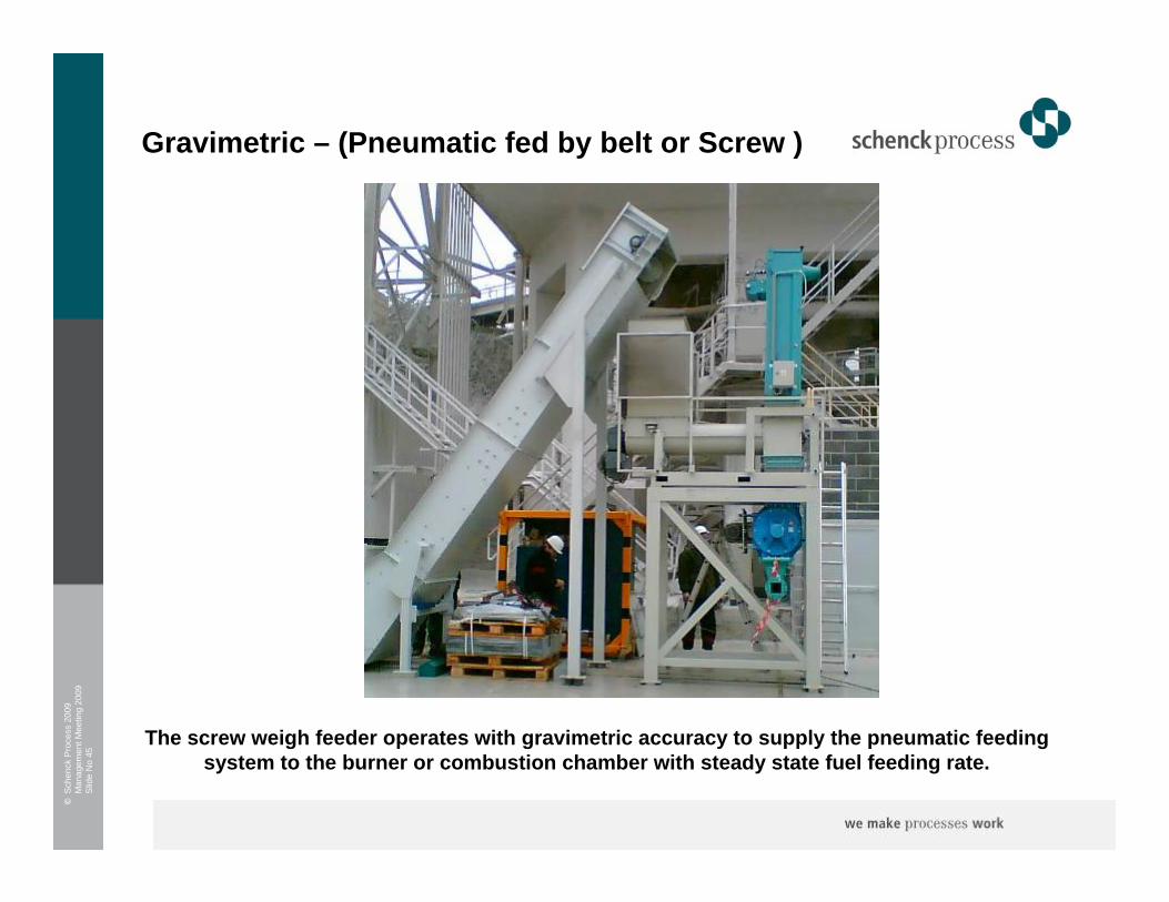
Gravimetric – (Pneumatic fed by belt or Screw )
The screw weigh feeder operates with gravimetric accuracy to supply the pneumatic feeding system to the burner or combustion chamber with steady state fuel feeding rate.
©S
chen
ck P
roce
ss 2
009
Man
agem
ent M
eetin
g 20
09S
lide
No
46
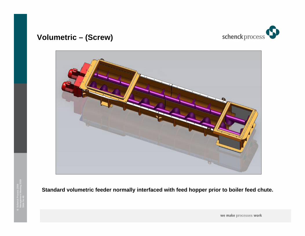
Volumetric – (Screw)
Standard volumetric feeder normally interfaced with feed hopper prior to boiler feed chute.

©S
chen
ck P
roce
ss 2
009
Man
agem
ent M
eetin
g 20
09S
lide
No
47
Volumetric – (Belt)
Standard volumetric belt feeder normally used to extract suitable fuel typesfrom storage and to interface with boiler feed chute.
©S
chen
ck P
roce
ss 2
009
Man
agem
ent M
eetin
g 20
09S
lide
No
48
5 Conclusions and Developments

©S
chen
ck P
roce
ss 2
009
Man
agem
ent M
eetin
g 20
09S
lide
No
49
Conclusions
Biomass handling, how hard can it be ?
However
• The materials certainly create challenges that drive extensive design implications far beyond the level that the material descriptions initially suggest
• Handling large volumes, typically 3 or 4 x the volume of coal for the same calorific value presents considerable handling difficulties
• The transport logistics and fuel availability will drive attempts to keep costs and supply volatility low
However
• We have overcome many of the handling hurdles and can now create optimized system designs that are less problematic and flexible enough to cope with variation in fuels and multiplefuel types
• We can no longer have to accept or rely on system that are based on agricultural technology. We have technologies that can supply optimized gravimetric fuel feeding at a level equal to those utilized within existing coal fired plants
• Unloading systems and handling systems are able to handle multiple fuels reducing thesupply pressure and allowing better management of market fluctuation.
Other industries and global markets have successfully handled biomass and other solid alternate fuels for many years
©S
chen
ck P
roce
ss 2
009
Man
agem
ent M
eetin
g 20
09S
lide
No
50
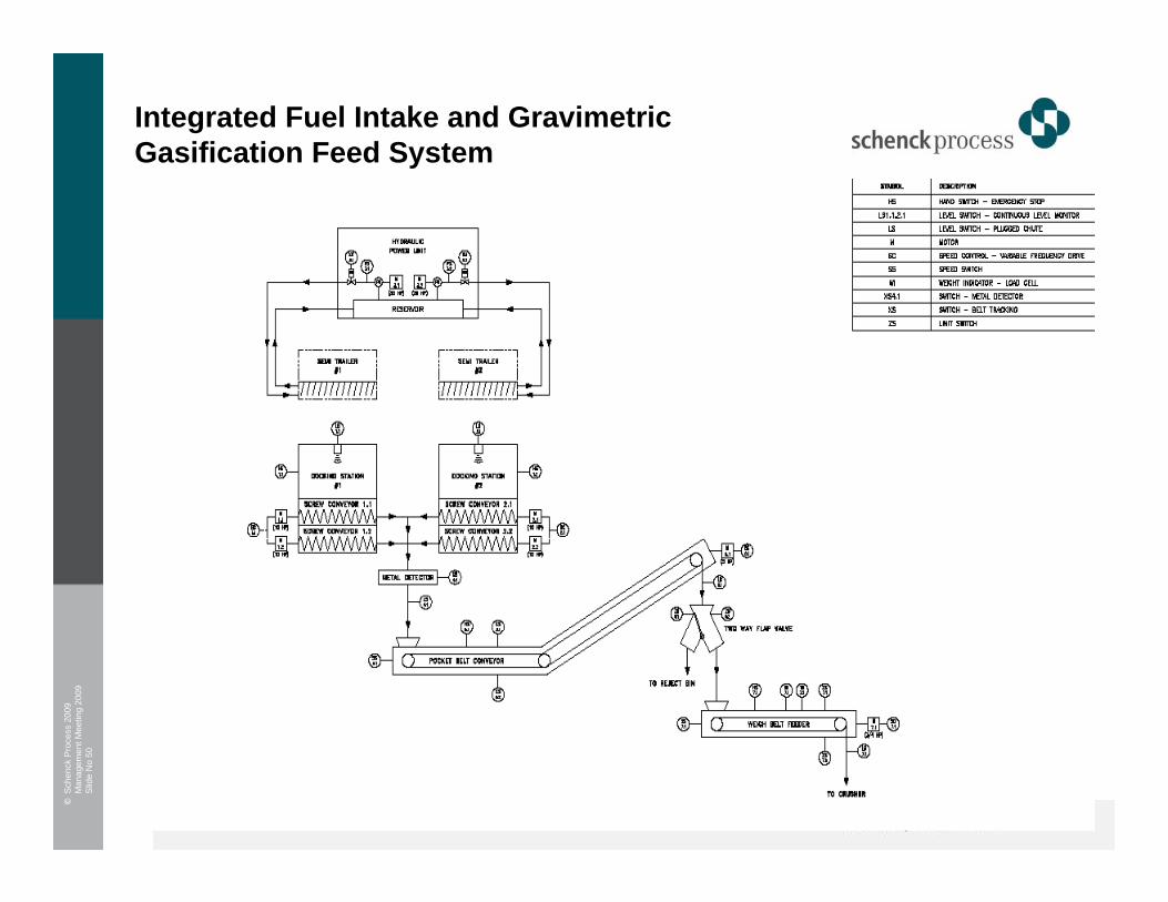
Integrated Fuel Intake and Gravimetric Gasification Feed System

©S
chen
ck P
roce
ss 2
009
Man
agem
ent M
eetin
g 20
09S
lide
No
51
Container Intake and Gravimetric Feeding System

©S
chen
ck P
roce
ss 2
009
Man
agem
ent M
eetin
g 20
09S
lide
No
52
Biomass Gasification System Feeding
©S
chen
ck P
roce
ss 2
009
Man
agem
ent M
eetin
g 20
09S
lide
No
53
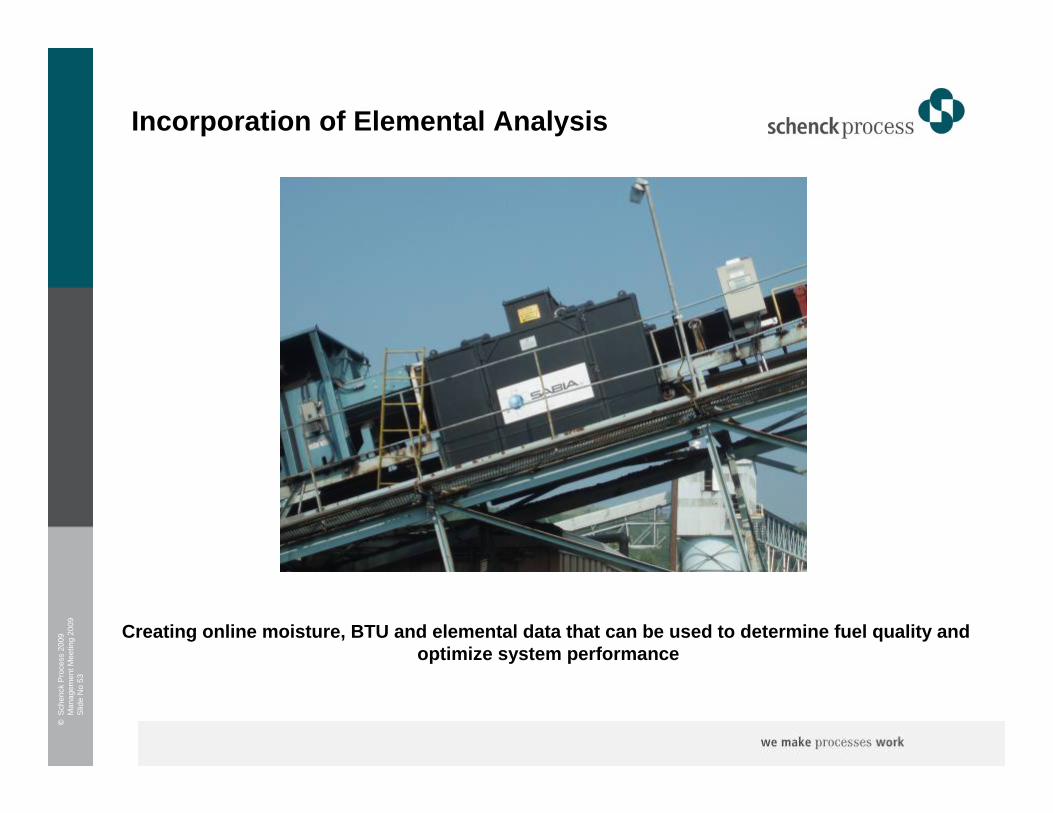
Incorporation of Elemental Analysis
Creating online moisture, BTU and elemental data that can be used to determine fuel quality and optimize system performance

©S
chen
ck P
roce
ss 2
009
Man
agem
ent M
eetin
g 20
09S
lide
No
54
Blending Layout Example
Main Fuel Feed Belt
Coal Silos
Gravimetric CoalFeeders
Muliflex Gravimetric Biomass Feeders
Biomass Silos
Elemental Analysis
The future could include elemental analysis to determine moisture and BTU value enabling optimized fuel blending and combustion.
©S
chen
ck P
roce
ss 2
009
Man
agem
ent M
eetin
g 20
09S
lide
No
55
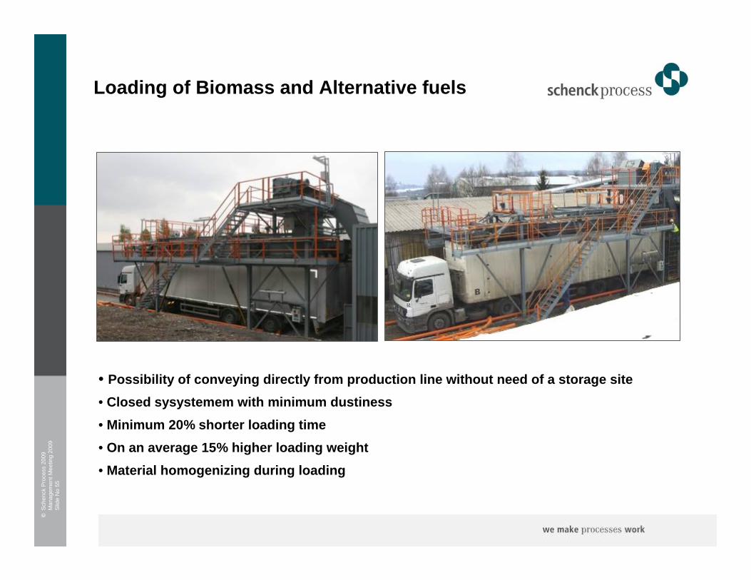
• Possibility of conveying directly from production line without need of a storage site• Closed sysystemem with minimum dustiness• Minimum 20% shorter loading time• On an average 15% higher loading weight• Material homogenizing during loading
x
Loading of Biomass and Alternative fuels
©S
chen
ck P
roce
ss 2
009
Man
agem
ent M
eetin
g 20
09S
lide
No
56
THANK YOU