worldwide locations - cyclo.shi.co.jpcyclo.shi.co.jp/document_v2/p1001e-1.0.1.pdf · rodovia do...
TRANSCRIPT

Planetary Gear Drive DP1000 Series
No.P1001E-1
COMPOWER
Headquarter 16-1, Wakihama 4-chome, Kaizuka-shi, Osaka 597-8555, Japan
Specifications, dimensions, and other items are subject to change without prior notice.
No.P1001E-1.0.1EA03
Worldwide LocationsU.S.ASumitomo Machinery Corporation of America (SMA)4200 Holland Blvd. Chesapeake,VA 23323,U.S.A.TEL (1)757-485-3355 FAX (1)757-485-7490
CanadaSM Cyclo of Canada, Ltd. (SMC)1453 Cornwall Road,Oakville, Canada ON L6J 7T5TEL (1)905-469-1050 FAX (1)905-469-1055
MexicoSM Cyclo de Mexico, S.A. de C.V. (SMME)Av. Desarrollo 541, Col. Finsa, Guadalupe,Nuevo León, México, CP67132TEL (52)81-8144-5130 FAX (52)81-8144-5130
BrazilSumitomo Industrias Pesadas do Brasil Ltda. (SHIB)Rodovia do Acucar (SP-075) Km 26 Itu, Sao Paulo, Brasil TEL (55)11-4886-1000 FAX (55)11-4886-1000
ChileSM Cyclo de Chile, Ltda. (SMCH)San Pablo 3507, Quinta Normal, Santiago, ChileTEL (56)2-892-7000 FAX (56)2-892-7001
ArgentinaSM Cyclo de Argentina S.A. (SMAR)Ing. Delpini, 2236Area de Promocion el Triangulo,Partido Malvinas Argentinas Grand Bourg,Buenos Aires, Argentina B1615KGBTEL (54)3327-45-4095 FAX (54)3327-45-4099
GuatemalaSM Cyclo de Guatemala Ensambladora, Ltda. (SMGT)Parque Industrial Unisur, 0 Calle B 19-50 Zona 3,Bodega D-1 Delta Bárcenas en Villa Nueva, GuatemalaTEL (502)6648-0500 FAX (502)6631-9171
ColombiaSM Cyclo Colombia, S.A.S.Carrera 11, No.93A-53, Office 203, Bogotá, ColombiaTEL (57)1-3000673
GermanySumitomo (SHI) Cyclo Drive Germany GmbH (SCG)Cyclostraße 92, 85229 Markt Indersdorf, GermanyTEL (49)8136-66-0 FAX (49)8136-5771
AustriaSumitomo (SHI) Cyclo Drive Germany GmbH (SCG)SCG Branch Austria OfficeGruentalerstraße 30A, 4020 Linz, AustriaTEL (43)732-330958 FAX (43)732-331978
BelgiumSumitomo (SHI) Cyclo Drive Germany GmbH (SCG)SCG Branch Benelux OfficeHeikneuterlaan 23, 3010 Kessel-Lo, Leuven, BelgiumTEL (32)16-60-83-11 FAX (32)16-60-16-39
FranceSM-Cyclo France SAS (SMFR)8 Avenue Christian Doppler, 77700 Serris, FranceTEL (33)164171717 FAX (33)164171718
ItalySM-Cyclo Italy Srl (SMIT)Via dell' Artigianato 23, 20010 Cornaredo (MI), ItalyTEL (39)293-481101 FAX (39)293-481103
SpainSM-Cyclo Iberia, S.L.U. (SMIB)C/Landabarri No. 3, 6° B, 48940 Leioa, Vizcaya, SpainTEL (34)9448-05389 FAX (34)9448-01550
SwedenSM-Cyclo Scandinavia AB (SMSC)Industrigatan 21B, 234 35 Lomma, SwedenTEL (46)40220030
United KingdomSM-Cyclo UK Ltd. (SMUK)Unit 29, Bergen Way, Sutton Fields Industrial Estate, Kingston upon Hull, HU7 0YQ, East Yorkshire, United KingdomTEL (44)1482-790340 FAX (44)1482-790321
TurkeySM Cyclo Turkey Güç Aktarım Sis. Tic. Ltd. Sti. (SMTR)Büyükdere Çayırbaşı Cd. Dede Yusuf Sk. No:11,34453 Sarıyer Istanbul, Turkey TEL (90)216-384-4482 FAX (90)216-384-4482
ChinaSumitomo (SHI) Cyclo Drive China, Ltd. (SCT) 11F,SMEG Plaza, No.1386 Hongqiao Road,Changning District, Shanghai, China (P.C.200336)TEL (86)21-3462-7877 FAX (86)21-3462-7922
Hong KongSM-Cyclo of Hong Kong Co.,Ltd. (SMHK)Rm 1301, CEO Tower, 77 Wing Hong Street,Cheung Sha Wan, Kowloon, Hong Kong TEL (852)2460-1881 FAX (852)2460-1882
KoreaSumitomo (SHI) Cyclo Drive Korea, Ltd. (SCK)Royal Bldg. 9F Rm.913, 5 Danju-Dong, Chongro-Ku,Seoul, Korea 110-721 TEL (82)2-730-0151 FAX (82)2-730-0156
TaiwanTatung SM-Cyclo Co., Ltd. (TSC)22 Chungshan N. Road 3rd., Sec. Taipei, Taiwan 104, R.O.C.TEL (886)2-2595-7275 FAX (886)2-2595-5594
SingaporeSumitomo (SHI) Cyclo Drive Asia Pacifi c Pte. Ltd. (SCA)15 Kwong Min Road, Singapore 628718TEL (65)6591-7800 FAX (65)6863-4238
PhilippinesSumitomo (SHI) Cyclo Drive Asia Pacific Pte. Ltd. (SCA)Philippines Branch OfficeB2B Granville Industrial Complex, Carmona, Cavite,PhilippinesTEL (63)2-584-4921 FAX (63)2-584-4922TEL (63)46-430-3591TEL (63)46-482-0580TEL (63)46-482-0581
VietnamSM-Cyclo (Vietnam) Co., Ltd.Factory 2B, Lot K1-2-5,Road No.: 2-3-5A,Le Minh Xuan Industrial Park, Binh Chanh Dist.,HCMC, Vietnam.TEL (84)8-37-663-709 FAX (84)8-37-663-710
MalaysiaSM-Cyclo of Malaysia Sdn. Bhd. (SMMA)No.7C, Jalan Anggerik Mokara 31/56, Kota Kemuning,Seksyen 31, 40460 Shah Alam, Selangor D.E., MalaysiaTEL (60)3-51210455 FAX (60)3-51210578
IndonesiaPT. SM-Cyclo IndonesiaCikarang Jalan Sungkai Blok F 25 No.09 K,Delta Silicon 5, Lippo Cikarang, Bekasi, IndonesiaTEL (62)21-2961-2100 FAX (62)21-2961-2211
ThailandSM-Cyclo (Thailand) Co., Ltd.195 Empire Tower, 21st Fl., Unit 2103-4, South Sathorn Rd.,Yannawa Sathorn, Bangkok 10120, ThailandTEL (66)2-670-0998 FAX (66)2-670-0999
AustraliaSumitomo (SHI) Hansen Australia Pty. Ltd. (SHAU)181 Power Street Glendenning NSW 2761, AustraliaTEL (61)2-9208-3000 FAX (61)2-9208-3050
IndiaSumi-Cyclo Drive India Pvt. Ltd. (SMIN)Survey No.130, Hissa No.02, Jeevan Nagar, Off Mumbai-Bangalore bypass, Tathawade, Pune-411 033, IndiaTEL (91)20-6674-2900 FAX (91)20-6674-2901
JapanSumitomo Heavy Industries, Ltd.ThinkPark Tower, 1-1 Osaki 2-chome, Shinagawa-ku,Tokyo 141-6025, JapanTEL (81)3-6737-2511 FAX (81)3-6866-5160
DP1000ENG.indd 64 17/03/25 13:53
Planetary Gear Drive DP1000 Series
No.P1001E-1
COMPOWER
Headquarter 16-1, Wakihama 4-chome, Kaizuka-shi, Osaka 597-8555, Japan
Specifications, dimensions, and other items are subject to change without prior notice.
No.P1001E-1.0.1EA03 2017.04
Worldwide LocationsU.S.ASumitomo Machinery Corporation of America (SMA)4200 Holland Blvd. Chesapeake,VA 23323,U.S.A.TEL (1)757-485-3355 FAX (1)757-485-7490
CanadaSM Cyclo of Canada, Ltd. (SMC)1453 Cornwall Road,Oakville, Canada ON L6J 7T5TEL (1)905-469-1050 FAX (1)905-469-1055
MexicoSM Cyclo de Mexico, S.A. de C.V. (SMME)Av. Desarrollo 541, Col. Finsa, Guadalupe,Nuevo León, México, CP67132TEL (52)81-8144-5130 FAX (52)81-8144-5130
BrazilSumitomo Industrias Pesadas do Brasil Ltda. (SHIB)Rodovia do Acucar (SP-075) Km 26 Itu, Sao Paulo, Brasil TEL (55)11-4886-1000 FAX (55)11-4886-1000
ChileSM Cyclo de Chile, Ltda. (SMCH)San Pablo 3507, Quinta Normal, Santiago, ChileTEL (56)2-892-7000 FAX (56)2-892-7001
ArgentinaSM Cyclo de Argentina S.A. (SMAR)Ing. Delpini, 2236Area de Promocion el Triangulo,Partido Malvinas Argentinas Grand Bourg,Buenos Aires, Argentina B1615KGBTEL (54)3327-45-4095 FAX (54)3327-45-4099
GuatemalaSM Cyclo de Guatemala Ensambladora, Ltda. (SMGT)Parque Industrial Unisur, 0 Calle B 19-50 Zona 3,Bodega D-1 Delta Bárcenas en Villa Nueva, GuatemalaTEL (502)6648-0500 FAX (502)6631-9171
ColombiaSM Cyclo Colombia, S.A.S.Carrera 11, No.93A-53, Office 203, Bogotá, ColombiaTEL (57)1-3000673
GermanySumitomo (SHI) Cyclo Drive Germany GmbH (SCG)Cyclostraße 92, 85229 Markt Indersdorf, GermanyTEL (49)8136-66-0 FAX (49)8136-5771
AustriaSumitomo (SHI) Cyclo Drive Germany GmbH (SCG)SCG Branch Austria OfficeGruentalerstraße 30A, 4020 Linz, AustriaTEL (43)732-330958 FAX (43)732-331978
BelgiumSumitomo (SHI) Cyclo Drive Germany GmbH (SCG)SCG Branch Benelux OfficeHeikneuterlaan 23, 3010 Kessel-Lo, Leuven, BelgiumTEL (32)16-60-83-11 FAX (32)16-60-16-39
FranceSM-Cyclo France SAS (SMFR)8 Avenue Christian Doppler, 77700 Serris, FranceTEL (33)164171717 FAX (33)164171718
ItalySM-Cyclo Italy Srl (SMIT)Via dell' Artigianato 23, 20010 Cornaredo (MI), ItalyTEL (39)293-481101 FAX (39)293-481103
SpainSM-Cyclo Iberia, S.L.U. (SMIB)C/Landabarri No. 3, 6° B, 48940 Leioa, Vizcaya, SpainTEL (34)9448-05389 FAX (34)9448-01550
SwedenSM-Cyclo Scandinavia AB (SMSC)Industrigatan 21B, 234 35 Lomma, SwedenTEL (46)40220030
United KingdomSM-Cyclo UK Ltd. (SMUK)Unit 29, Bergen Way, Sutton Fields Industrial Estate, Kingston upon Hull, HU7 0YQ, East Yorkshire, United KingdomTEL (44)1482-790340 FAX (44)1482-790321
TurkeySM Cyclo Turkey Güç Aktarım Sis. Tic. Ltd. Sti. (SMTR)Büyükdere Çayırbaşı Cd. Dede Yusuf Sk. No:11,34453 Sarıyer Istanbul, Turkey TEL (90)216-384-4482 FAX (90)216-384-4482
ChinaSumitomo (SHI) Cyclo Drive China, Ltd. (SCT) 11F,SMEG Plaza, No.1386 Hongqiao Road,Changning District, Shanghai, China (P.C.200336)TEL (86)21-3462-7877 FAX (86)21-3462-7922
Hong KongSM-Cyclo of Hong Kong Co.,Ltd. (SMHK)Rm 1301, CEO Tower, 77 Wing Hong Street,Cheung Sha Wan, Kowloon, Hong Kong TEL (852)2460-1881 FAX (852)2460-1882
KoreaSumitomo (SHI) Cyclo Drive Korea, Ltd. (SCK)Royal Bldg. 9F Rm.913, 5 Danju-Dong, Chongro-Ku,Seoul, Korea 110-721 TEL (82)2-730-0151 FAX (82)2-730-0156
TaiwanTatung SM-Cyclo Co., Ltd. (TSC)22 Chungshan N. Road 3rd., Sec. Taipei, Taiwan 104, R.O.C.TEL (886)2-2595-7275 FAX (886)2-2595-5594
SingaporeSumitomo (SHI) Cyclo Drive Asia Pacifi c Pte. Ltd. (SCA)15 Kwong Min Road, Singapore 628718TEL (65)6591-7800 FAX (65)6863-4238
PhilippinesSumitomo (SHI) Cyclo Drive Asia Pacific Pte. Ltd. (SCA)Philippines Branch OfficeB2B Granville Industrial Complex, Carmona, Cavite,PhilippinesTEL (63)2-584-4921 FAX (63)2-584-4922TEL (63)46-430-3591TEL (63)46-482-0580TEL (63)46-482-0581
VietnamSM-Cyclo (Vietnam) Co., Ltd.Factory 2B, Lot K1-2-5,Road No.: 2-3-5A,Le Minh Xuan Industrial Park, Binh Chanh Dist.,HCMC, Vietnam.TEL (84)8-37-663-709 FAX (84)8-37-663-710
MalaysiaSM-Cyclo of Malaysia Sdn. Bhd. (SMMA)No.7C, Jalan Anggerik Mokara 31/56, Kota Kemuning,Seksyen 31, 40460 Shah Alam, Selangor D.E., MalaysiaTEL (60)3-51210455 FAX (60)3-51210578
IndonesiaPT. SM-Cyclo IndonesiaCikarang Jalan Sungkai Blok F 25 No.09 K,Delta Silicon 5, Lippo Cikarang, Bekasi, IndonesiaTEL (62)21-2961-2100 FAX (62)21-2961-2211
ThailandSM-Cyclo (Thailand) Co., Ltd.195 Empire Tower, 21st Fl., Unit 2103-4, South Sathorn Rd.,Yannawa Sathorn, Bangkok 10120, ThailandTEL (66)2-670-0998 FAX (66)2-670-0999
AustraliaSumitomo (SHI) Hansen Australia Pty. Ltd. (SHAU)181 Power Street Glendenning NSW 2761, AustraliaTEL (61)2-9208-3000 FAX (61)2-9208-3050
IndiaSumi-Cyclo Drive India Pvt. Ltd. (SMIN)Survey No.130, Hissa No.02, Jeevan Nagar, Off Mumbai-Bangalore bypass, Tathawade, Pune-411 033, IndiaTEL (91)20-6674-2900 FAX (91)20-6674-2901
JapanSumitomo Heavy Industries, Ltd.ThinkPark Tower, 1-1 Osaki 2-chome, Shinagawa-ku,Tokyo 141-6025, JapanTEL (81)3-6737-2511 FAX (81)3-6866-5160
DP1000ENG.indd 1 17/03/23 21:08

DP1000ENG.indd 2DP1000ENG.indd 2 15/05/14 10:5315/05/14 10:53

FeaturesAvailable Combination
Reducer and Drive unit
A-2
A-4
Reducer Standard SpecificationsConstruction DrawingNomenclatureSelectionService Factor SFSelection TablesAllowable Radial Load on Low Speed ShaftAllowable Radial Load on High Speed ShaftDimension Tables
B-2B-3B-4B-6B-8B-10B-28B-29B-30
Technical Data Lubrication and InstallationPainting Specifications and Rust Proof StandardMoment of InertiaSpecifications/Dimensions for Spline shaftDimensions of Motor Adapter JEM / IECWarranty PolicySafety PrecautionsInquiry / Order Specification Sheet form
C-2C-3C-4C-6C-7C-8C-9C-10
CONTENTS
A
B
C
DP1000ENG.indd 3DP1000ENG.indd 3 15/05/14 10:5315/05/14 10:53

DP1000ENG.indd 4DP1000ENG.indd 4 15/05/14 10:5315/05/14 10:53

A
Features A-2
Available Combination
Reducer and Drive Unit A-4
Features
DP1000ENG.indd 5DP1000ENG.indd 5 15/05/14 10:5315/05/14 10:53

■ A Features●●●●●●●●●●●●●●●●●●
A-2
Features
“TOUGH, COMPACT & SIMPLE”1 Wide Variation of Lineup
Applicable to various specifications with less number of parts by adopting modular design. Wide selection of Planetary Gear Reducer DP1000 Series for better choice of customer’s requests. ①Availability of Output Torque from 0.46kNm to 736kNm and Power Range from 0.2kW to 1200kW. ②Applicable to Reduction Ratio from 1/5 to 1/1400. ③Applicable to foot mounting, flange mounting and shaft mounting(option).
Size of Reducer/torque(kNm)
Reduction ratio
5916182022.4252831.535.540455056637180901001121251401601802002242502803153554004505005606307108009001000112012501400
1010 1020 1030 1040 1050 1060 1070 1080 1090 1100 1110 1120 1130 1140 1150 1160 1170 1180 1185 1190 1195 1200 1205 1210 1215 12200.46 0.69 1 1.6 3.2 5.5 8.6 13.6 15.9 22.6 29.4 39.2 53 72.6 95.2 128 157 186 225 275 343 402 451 549 647 736
DP1000ENG.indd A-6DP1000ENG.indd A-6 15/05/14 17:2815/05/14 17:28

A-3
A Features ■●●●●●●●●●●●●●●●●●●
3-Phase Motor
2 Drive Unit
Prepared full lineup of direct motor mount type drive units. Simple layout of models can be made due to the unified combination of reducer and basic motor. Eliminate the necessity for foundation working for installation and alignment operation.
3 High strength and rigidity of Planetary Gear system.
①Equal distribution of Planetary Gear system. Optimum distribution of load to each gear is secured by Planetary Gear system and structure. Slimmer diameter can produce bigger transmission power of torque. ②High pressure angle gear. 27-degree pressure angle provides higher tooth strength, which is good for shock loads.
- With brake - With brake - With brake - With brake - With brake
● ● ● ● ● ●● ●● ● ● ● ● ●● ● ● ●
● ● ● ●● ●● ● ● ●● ● ● ●● ●● ● ● ●● ● ● ●● ● ● ●● ● ● ●● ● ● ●● ● ● ●● ● ● ●● ● ● ●● ● ● ●● ● ●●
Time rating : S1 (Continuous rating)Applicable voltage : [Standard] 200V 50/60Hz 220V 60Hz or 400V 50/60Hz 440V 60Hz [For inverter drive] 200V 60Hz 220V 60Hz or 400V 60Hz 440V 60HzAbout motor with brake : ESB-brake is for 200V-class. In the case power source is 400V-class, use power-transformer for 400V/200V.
4P 4P
Specifications
Motor-type
kW
High efficiency 3-Phase Motor
Premium Efficiency 3-Phase Motor forinverter drive
AF motor forinverter drive
Premium Efficiency 3-Phase Motor
4P 4P 4P
Standard 3-Phase induction motors / 3-Phase induction motors with brake (Indoor type / Outdoor type)
1. Motors with other voltage than as listed are manufactured. Consult us.2. Consult us about embironmental options, for example outdoor type(IP55), special voltage, dust-proof, explosion-proof, corrosion -proof, water-proof, overseas standard and so on.
0.20.250.40.550.751.11.52.23.03.75.57.5111518.52230374555
DP1000ENG.indd A-7DP1000ENG.indd A-7 15/05/14 17:2815/05/14 17:28

■ A Features●●●●●●●●●●●●●●●●●●
A-4
■Available CombinationReducer
●:Standard Models ○:Manufactured Models (Option)
Remark: This table is applicable only to shaft inline type in the catalogue.
Drive Unit
Motor
Remark: This table is applicable only for shaft inline type in the catalogue.
Size
5 9 16 18 20 22.4 25 28 31.5 35.5 40 45 50 56 63 71 80 90 100 112 125
1010 ● ● ● ● ● ● ● ● ● ●
1020 ● ● ● ● ● ● ● ● ● ●
1030 ● ● ● ● ● ● ● ● ● ●
1040 ● ● ● ○ ○ ● ● ○ ● ● ● ● ●
1050 ● ● ● ○ ○ ● ● ○ ● ● ○ ○ ● ○ ● ○ ○ ●
1060 ● ● ● ○ ○ ● ○ ○ ● ○ ● ● ○ ○ ● ○ ● ○ ○ ●
1070 ● ● ● ○ ○ ● ○ ○ ● ○ ● ○ ● ○ ○ ● ○ ● ○ ○ ●
1080 ● ○ ○ ● ○ ○ ● ○ ● ○ ● ○ ○ ● ○ ● ○ ○ ●
1090 ● ○ ○ ● ○ ○ ● ○ ○ ○ ● ○ ○ ● ○ ● ○ ○ ●
1100 ○ ○ ● ● ● ● ● ● ● ● ● ○ ○ ● ○ ○
1110 ○ ○ ● ● ● ● ● ● ● ● ● ○ ○ ● ○ ○
1120 ○ ○ ● ● ● ● ● ● ● ● ● ○ ○ ● ○ ○
1130 ○ ○ ● ● ● ● ● ● ● ● ● ○ ○ ● ○ ○
1140 ○ ○ ● ● ● ● ● ● ● ● ○ ○ ● ● ● ●
1150 ● ● ● ● ● ●
1160 ● ● ● ● ● ●
1170 ● ● ● ● ●
1180 ● ● ● ● ●
1185 ● ● ● ●
1190 ● ● ● ● ●
1195 ● ● ● ● ●
1200 ● ● ● ●
1205 ● ● ●
1210 ● ● ● ●
1215 ● ● ● ●
1220 ● ● ● ● ●
5 9 16 18 20 22.4 25 28 31.5 35.5 40 45 50 56 63 71 80 90 100 112 125
60Hz 360 200 113 100 90 80 72 64 57 51 45 40 36 32 29 25 23 20 18 16 14
50Hz 300 167 94 83 75 67 60 54 48 42 38 33 30 27 24 21 19 17 15 13 12
0.2×4 ● ● ●
0.4×4 ● ● ●
0.75×4 ● ● ● ● ● ●
1.5×4 ● ● ● ● ● ● ● ● ●
2.2×4 ● ● ● ● ● ● ● ● ● ●
3.7×4 ● ● ● ● ● ● ● ● ● ●
5.5×4 ● ● ● ● ● ● ● ● ● ●
7.5×4 ● ● ● ● ● ● ● ● ● ●
11×4 ● ● ● ● ● ● ● ● ● ●
15×4 ● ● ● ● ● ● ● ● ● ●
18.5×4 ● ●
22×4 ● ● ● ● ● ● ● ● ● ● ●
30×4 ● ● ● ● ● ● ● ●
37×4 ● ● ● ● ● ● ● ● ● ●
45×4 ● ● ● ● ● ● ●
55×4 ● ● ● ● ● ●
Ratio
Ratio
O/P speed
r/min
(kW×P)
DP1000ENG.indd A-8DP1000ENG.indd A-8 15/05/14 17:2815/05/14 17:28

A-5
A Features ■●●●●●●●●●●●●●●●●●●
Ratio
Size
O/P speed
Motor
(kW×P)
r/min
Ratio
140 160 180 200 224 250 280 315 355 400 450 500 560 630 710 800 900 1000 1120 1250 1400
● ● ● ● ● ● ● ● 1010
● ● ● ● ● ● ● ● 1020
● ● ● ● ● ● ● ● 1030
● ● ● ● ● ● ● ● 1040
○ ○ ● ○ ● ● ● ● ● ● ● 1050
○ ○ ● ○ ● ● ● ● ● ● ● 1060
○ ○ ● ○ ● ● ● ● ● ● ● 1070
○ ○ ● ○ ● ● ○ ● ○ ○ ● ○ ○ ● ○ ○ ● ○ ● 1080
○ ○ ● ○ ● ● ○ ● ○ ○ ● ○ ○ ● ○ ○ ● ○ ● 1090
● ○ ● ● ○ ● ○ ○ ● ○ ○ ● ○ ● ● ○ ● 1100
● ○ ● ○ ● ○ ● ○ ○ ● ○ ○ ● ○ ● ● ○ ● 1110
● ○ ● ○ ● ○ ● ○ ○ ● ○ ○ ● ○ ● ● ○ ● 1120
● ○ ○ ○ ● ○ ● ○ ○ ● ○ ○ ● ○ ○ ● ○ ● 1130
● ● ● ● ● ○ ○ ● ○ ○ ● ○ ● 1140
● ● ● ● ● ● ● ● ● ● ● ● ● ● 1150
● ● ● ● ● ● ● ● ● ● ● ● ● ● 1160
● ● ● ● ● ● ● ● ● ● ● ● ● ● 1170
● ● ● ● ● ● ● ● ● ● ● ● ● ● ● 1180
● ● ● ● ● ● ● ● ● ● ● ● 1185
● ● ● ● ● ● ● ● ● ● ● ● ● ● ● 1190
● ● ● ● ● ● ● ● ● ● ● ● 1195
● ● ● ● ● ● ● ● ● ● ● ● ● ● 1200
● ● ● ● ● ● ● ● ● ● ● ● ● 1205
● ● ● ● ● ● ● ● ● ● ● ● ● ● ● 1210
● ● ● ● ● ● ● ● ● ● ● ● ● ● 1215
● ● ● ● ● ● ● ● ● ● ● ● ● ● ● 1220
140 160 180 200 224 250 280 315 355 400 450 500 560 630 710 800 900 1000 1120 1250 1400
13 11 10 9.0 8.0 7.2 6.4 5.7 5.1 4.5 4.0 3.6 3.2 2.9 2.5 2.3 2.0 1.8 1.6 1.4 1.3
11 9.4 8.3 7.5 6.7 6.0 5.4 4.8 4.2 3.8 3.3 3.0 2.7 2.4 2.1 1.9 1.7 1.5 1.3 1.2 1.1
● ● ● ● ● ● ● ● 0.2×4
● ● ● ● ● ● ● ● 0.4×4
● ● ● ● ● ● ● ● 0.75×4
● ● ● ● ● ● ● ● ● 1.5×4
● ● ● ● ● ● ● ● ● 2.2×4
● ● ● ● ● ● ● ● ● ● 3.7×4
● ● ● ● ● ● ● ● 5.5×4
● ● ● ● ● ● ● ● 7.5×4
● ● ● ● ● ● ● 11×4
● ● ● ● ● 15×4
● ● ● ● ● ● 18.5×4
● ● ● ● ● ● ● 22×4
● 30×4
37×4
45×4
55×4
60Hz
50Hz
DP1000ENG.indd A-9DP1000ENG.indd A-9 15/05/14 17:2815/05/14 17:28

A-6
DP1000ENG.indd A-10DP1000ENG.indd A-10 15/05/14 17:2815/05/14 17:28

Reducer
Standard Specifications B-2
Construction Drawing B-3
Nomenclature B-4
Selection B-6
Service Factor SF B-8
Selection Tables B-10
Allowable Radial Load on Low Speed Shaft B-28
Allowable Radial Load on High Speed Shaft B-29
Dimension Tables B-30
B
Reducer
DP1000ENG.indd 11DP1000ENG.indd 11 15/05/14 10:5315/05/14 10:53

■ B Reducer●●●●●●●●●●●●●●●●●●
B-2
■Reducer Standard SpecificationsItem Standard Specification
Lubrication Method
Oil bath lubrication (Some of the upper bearing are lubricated with grease)
LubricantReduction Method Involute Planetary Gear Re
ducer
Shaft Direction Rotation direction of high speed shaft is the same as output shaft
Installation Location Indoor (Minimal dust and humidity)
Ambient Temperature -10℃~40℃ (Note1)
Ambient Humidity Under 85%
ElevationAmbient Conditions
Atmosphere Well-ventilated location, free of corrosive gas, explosive gas, vapors and dust.
Installation Horizontal installation Refer to the page C-2.
Method of Coupling with driven Machine
Coupling, gears, chain sprocket or belt.
Painting
Surface preparation: Shot blasting after washing before machining. Inside painting: Power Bind PTC Grey is sprayed once. Outside painting: For prime coating, Power Bind PTC Grey is sprayed once.
For final coating, SUPIKA#3000 is sprayed once. Painting color: Donau Blue (equivalent Munsell color: 6.5PB 3.6 / 8.2). Refer to the page C-3.
Note1: A heating or cooling system is necessary in case the ambient temperature is lower than -10℃ or higher than +40℃.
Refer to the page C-2
Under 1,000 meters
DP1000ENG.indd 12DP1000ENG.indd 12 15/05/14 10:5315/05/14 10:53

B-3
B Reducer ■●●●●●●●●●●●●●●●●●●
■Construction Drawing
No. Part Name No. Part Name
Low-Speed Shaft 1 5
6 Sun GearHousing2
Bearing 3 7 High-Speed side Cover
4 High-Speed Shaft8 Planetary Gear
DHG(foot mount type)
Internal Gear
DP1000ENG.indd 13DP1000ENG.indd 13 15/05/22 18:5815/05/22 18:58

■ B Reducer●●●●●●●●●●●●●●●●●●
B-4
■Nomenclature
Size Torque kNm
HG Horizontal (Blank) Solid Shaft
D
HF Horizontal Flange J Motor Adaptor
DP 1000Series
Planetary GearDrive
VF Vertical Flange JM Motor Adaptor + Motor
Remarks: Above figures of Torque show the transmission power of low speed shaft.
HY Shaft mounting(Option)
D HG 1090
Series Shaft Direction and Mounting Style Connection for Motor
1010 0.46 1020 0.69 1030 1.0 1040 1.6 1050 3.2 1060 5.5 1070 8.6 1080 13.6 1090 15.9 1100 22.6 1110 29.4 1120 39.2 1130 53.0 1140 72.6 1150 95.2 1160 128 1170 157 1180 186 1185 225 1190 275 1195 343 1200 402 1205 451 1210 549 1215 647 1220 736
DP1000ENG.indd 14DP1000ENG.indd 14 15/05/14 10:5415/05/14 10:54

B-5
B Reducer ■●●●●●●●●●●●●●●●●●●
Direction of High Speed Shaft
(Blank) Inline (Blank) Solid Shaft Key type
(Blank) Standard Specification
G※ Right angle(Option)
P Spline(Option)
F Cooling Fan(Option)
※Following Direction code will be added.
Direction code (View from A)
※”GR” will apply to VF type in spite of Direction code.
T Hollow Shaft Shrink Disk type (Option)
R Radial Case(Option)
90
View from A
L R
U
D down
left right
up
Low Speed Shaft Option Nominal Ratio
5 9 16 18 20 22.4 25 28 31.5 35.5 40 45 50 56 63 71 80 90 100 112 125 140 160 180 200 224 250 280 315 355 400 450 500 560 630 710 800 900 1000 1120 1250 1400
DP1000ENG.indd 15DP1000ENG.indd 15 15/05/14 10:5415/05/14 10:54

■ B Reducer●●●●●●●●●●●●●●●●●●
B-6
■Reducer Selection
DP1000ENG.indd 16DP1000ENG.indd 16 15/05/14 10:5415/05/14 10:54

B-7
B Reducer ■●●●●●●●●●●●●●●●●●●
■Reducer Selection ExampleConditions and final selections ○:Conditions ■:Selected item Reference page No.
B-2:Standard Specification
B-8:Service Factor
B-4~B-5:Nomenclature
B-16:Selection Tables
B-32*1:Dimension Tables Code in Dimension Tables
B-9:Selection Tables B-9:Selection Tables B-14:Selection Tables
B-28:Allowable Radial Load
B-28:Allowable Radial Load
○ Ambient Condition ■ Check ambient condition
○ Motor power ○ High speed shaft speed ○ Shaft and mounting positions
Load condition ○ Type of load, operating hours, usage ■ Determine Service Factor
■ Calculate equivalent transmission power
○ Low speed shaft speed ■ Reduction ratio Select nominal reduction ratio
■ Determine size
■ Determine reducer size, type, reduction ratio
■ Check dimension ■ Check nomenclature
○ Ambient Temperature ■ Temperature correction factor K1 ■ Temperature correction factor K2 ■ Thermal power rating PT
Check overhang load ○ Overhang member ■ Overhang factor K3 ○ Radial load position ○ Radial load Fr ■ Equivalent radial load FrE ■ Allowable radial load
7580.6 = 0.93 < 1
○ Completion of selection ■ Model selected
*1 page number of the relevant Dimension Table is indicated in the Selection Table.
:indoor, Ambient temperature 20℃→OK
:22kW(Code:30):1500r/min :Right Angle Shaft, Horizontal Mounting
:Uniform load: 14 hours/day, conveyor
→PE=22×1.25=27.5kW
:20r/min →1500/20=75 →75→71
→ Size 1080 Nominal reduction ratio 71Mechanical power rating PN=30.8kW
PE ≦ PN → OK
→DHG-1080-71
:20℃→K1=1.0→K2=1.0→PT=27.2kW→PT×K1×K2=27.2>22=PM→OK
:Sprocket (Single row)→K3=1.0:Center of shaft :60kN →FrE=60×1.25×1.0=75kN →80.6kN
→OK
→DHG-1080-71
→SF=1.25
DP1000ENG.indd 17DP1000ENG.indd 17 15/05/14 10:5415/05/14 10:54

■ B Reducer●●●●●●●●●●●●●●●●●●
B-8
■Service Factorer SF Service Factor Table for Driven Machines
Operating Hours(hours/day)Driven Machine 3 hrs 10 hrs 24 hrs
CRANES
CONVEYORS(General purpose)Uniformly load or fed Heavy load Not uniformly fed Reciprocating or shaker
ELEVATORS Elevators Escalators
METAL MILLS Draw bench carriage・main drive Runout table Non reversing
Group drives Individual drives
Reversing Slab pushers Shears Wire drawing Wire winding machine
Bridles Coilers & uncoilers Edge trimmers Flatteners Loopers Pinch rolls Scrap choppers Shears Slitters
MILL、ROTARY TYPE Ball、Rod Cement Kilns Kilns (Except cement kilns) Dryers、Coolers
SEWAGE DISPOSAL EQUIPMENT Aerators Bar screens Chemical feeders Dewatering screens Scum breakers mixers Sludge collectors Thickeners Vacuum filters
EXTRUDERS Plastics Rubber
FEEDERS Apron Belt Disk Reciprocating Screw
RUBBER INDUSTRY Mixers Mixing mill -2smooth rolls Batch drop mill -2smooth rollsCracker warmer -2roll:1 corrugated roll Cracker 2 corrugated rolls Holding, feed & blend mill -2rolls
Refiner -2 rolls Calenders
PAPER MILL Alltypes incl.Paper making machine
AGITATORS Liquids Liquids and solids Liquids Variable density
MIXERS Concrete
CRUSHER Stone
BLOWERS Centrifugal Lobe Vane
COMPRESSORS Centrifugal Lobe Reciprocating:multi cylinder Reciprocating:single cylinder
FANS Centrifugal Cooling towers Forced draft Suction draft Idustrial and mine
PUMPS Centrifugal Screw pump Gear pump
DREDGES Cable reels Conveyors Cutter head drive Pumps Screen drives Stackers Winches
GENERATORS HAMMER MILLS SUGAR INDUSTRY Beet slicer Cane knives Crushers Mills
Notes (1) Values in the above table are based on AGMA standard and our experience.(2) Values in the above table apply for electric motors as prime movers if prime mover is a multi cylinder combustion engine, 0.25 has to be added to the SF. (3) Consult us for special duty or when special safety specifications are needed. (4) ※:Consult us.
The crane classification isbased on JIS 「Calculation standard for the structure of crane」
Classificationof crane Hoisting Traverse
MotionTravelMotion
SlewingMotion
BoomHoisting
GroupⅠ 1.00 1.50 1.25 1.00GroupⅡ 1.25 1.50 1.00GroupⅢ 1.50 1.75 1.25GroupⅣ 1.75 2.00 1.50
MATAL STRIP PROCESSING MACHINERY
1.00 1.00 1.25
1.00 1.25 1.501.50 1.75 2.00
1.50 1.50 1.501.25 1.25 1.25
1.50 1.50 1.50
1.50 1.50 1.502.00 2.00 2.002.00 2.00 2.001.50 1.50 1.502.00 2.00 2.001.25 1.25 1.251.25 1.50 1.50
1.50 1.50 1.501.00 1.25 1.501.00 1.25 1.501.25 1.25 1.501.50 1.50 2.001.25 1.25 1.502.00 2.00 2.002.00 2.00 2.001.00 1.25 1.50
2.00 2.00 2.002.00 2.00 2.001.50 1.50 1.501.50 1.50 1.50
2.00 2.00 2.001.25 1.25 1.251.25 1.25 1.251.50 1.50 1.501.50 1.50 1.501.50 1.50 1.501.25 1.25 1.251.50 1.50 1.501.50 1.50 1.50
1.25 1.25 1.251.50 1.50 1.50
1.00 1.25 1.501.00 1.25 1.501.00 1.00 1.251.50 1.75 2.001.00 1.25 1.50
Operating Hours(hours/day)Driven Machine 3 hrs 10 hrs 24 hrs
1.75 1.75 2.00 1.50 1.50 1.75 1.50 1.50 1.50
1.75 1.75 1.75 2.00 2.00 2.00
1.25 1.25 1.25 1.50 1.50 1.50 1.50 1.50 1.50
2.00 2.00 2.00
1.00 1.00 1.25 1.00 1.25 1.50 1.00 1.25 1.50
1.25 1.25 1.50
2.50 2.50 2.50
1.00 1.00 1.25 1.00 1.25 1.50 1.00 1.25 1.50
1.00 1.00 1.25 1.00 1.25 1.50 1.50 1.50 1.75 1.75 1.75 2.00
1.00 1.00 1.25 ※ ※ ※ 1.25 1.25 1.25 1.50 1.50 1.50 1.50 1.50 1.50
1.00 1.00 1.25 1.25 1.25 1.50 1.25 1.25 1.50
1.25 1.25 1.50 1.25 1.25 1.50 2.00 2.00 2.00 2.00 2.00 2.00 1.75 1.75 2.00 1.25 1.25 1.50 1.25 1.25 1.50 1.00 1.00 1.25 1.75 1.75 2.00
2.00 2.00 2.00 1.50 1.50 1.50 1.50 1.50 1.50 1.75 1.75 1.75
DP1000ENG.indd 18DP1000ENG.indd 18 15/05/14 10:5415/05/14 10:54

B-9
B Reducer ■●●●●●●●●●●●●●●●●●●
Refer to the following for driven machines not shown on the left page.
Prime Mover Operating Hours Uniform LoadU
Type of LoadModerate Shock Load
MHeavy Shock Load
H
Electric Motor3 hours/day10 hours/day24 hours/day
Internal CombustionEngine
(multi cylinder)
3 hours/day10 hours/day24 hours/day
Note: Consult us when the operating hours are less then 3 hours/day or when an internal combustion engine (single cylinder) is used.
Temperature correction factor K1 K1
Ambient temperature(℃)Load ratio per hour
Note: Use 100% in case the continuous operating hours will be more than two hours.
Temperature correction factor K2
K2Location
Indoor/closed
Indoor/open(Factory in general)
Outdoor/without directsunlight
Wind
≧0.5m/s
≧1.4m/s
≧3.7m/s
0.7
1.0
1.4
Overhang factor K3
Overhang Member
Sprocket(single row)
Sprocket(double row)
Gear
V-belt
Flat belt
K3
1
1.25
1.25
1.5
2.5
The starting torque and the stalling torque of premium efficiency 3-phase motors is largerthan conventional motors. It is necessary to reexamine service-factor when the motor is driven with thestarting-stopping in direct input of commercial power. Consult us.
100% 1.15 1.00 0.85 0.70 0.55
80% 1.35 1.20 1.00 0.80 0.65
60% 1.55 1.40 1.15 0.95 0.75
40% 1.75 1.60 1.35 1.10 0.90
20% 1.95 1.80 1.50 1.20 1.00
Under 10 20 30 40 50
1.001.001.25
1.001.251.50
1.501.752.00
1.001.251.50
1.251.501.75
1.752.002.25
DP1000ENG.indd 19DP1000ENG.indd 19 15/05/14 10:5415/05/14 10:54

■ B Reducer●●●●●●●●●●●●●●●●●●
B-10
Reduction ratio 5・9
Mechanical Power Rating PN
Size of Reducer
NominalReductionRatio
9
Dimension Tables HorizontalFlange, Horizontal
Thermal Power Rating PT
Notes:
1. The high speed shaft speed shall be under 1800 r/min. Consult us when it will be over 1800r/min.
2. When the high speed shaft speed is not shown in the table, find it by the interpolation method.
3. When the high speed shaft speed (n1) id lower than 750 r/min, find the mechanical power rating (PN) according to the following formula.
PN=P750×N750
4. Shown in the table are the ratings for the high speed shaft of reducer.
5. The thermal power ratings (PT) are applicable to continuous operation at ambient temperatures of 20℃ or less.
r/min r/min 1010 1020 1030 1040 1050 1060 1070 1080 1090 1100 1110
1800 360 4.39 7.65 11.7 11.7 23.5 43.0 86.9 1500 300 3.67 6.33 9.80 10.1 19.6 35.8 72.4 1200 240 2.86 5.10 7.86 8.06 15.7 28.7 58.0 1000 200 2.45 4.18 6.53 6.73 13.1 23.9 48.3 900 180 2.14 3.78 5.92 6.12 11.7 21.5 43.5 750 150 1.84 3.16 4.90 5.10 9.80 18.0 36.2 Exact Reduction Ratio 8.700 8.700 8.700 8.700 8.700 8.700 8.700 1800 200 2.65 3.98 7.86 9.29 18.0 36.8 48.2 1500 167 2.24 3.88 6.53 7.76 15.3 30.6 45.9 1200 133 1.84 3.06 5.20 6.22 12.2 24.5 36.7 1000 111 1.53 2.55 4.39 5.10 10.2 20.4 30.6 900 100 1.33 2.35 3.88 4.59 9.18 18.4 27.6 750 83 1.12 1.94 3.27 3.88 7.65 15.3 23.0 B-30 B-30 B-30 B-30 B-30 B-30 B-30 B-36 B-36 B-36 B-36 B-36 B-36 B-36 12.1 12.1 17.6 23.4 34.7 49.6 67.2
H. Speed Shaft Speed n1
L. Speed Shaft Speedn2
■Selection Table Reducer
DP1000ENG.indd 20DP1000ENG.indd 20 15/05/14 10:5415/05/14 10:54

B-11
B Reducer ■●●●●●●●●●●●●●●●●●●
Unit: kW
Size of Reducer1120 1130 1140 1150 1160 1170 1180 1190 1200 1210 1220
DP1000ENG.indd 21DP1000ENG.indd 21 15/05/14 10:5415/05/14 10:54

■ B Reducer●●●●●●●●●●●●●●●●●●
B-12
B-31 B-31 B-31 B-31 B-31 B-31 B-31 B-31 B-31 B-31 B-31 B-37 B-37 B-37 B-37 B-37 B-37 B-37 B-37 B-37 B-37 B-37 6.0 6.0 8.8 11.7 17.3 24.8 33.6 40.9 48.0 48.5 57.6
■Selection Table Reducer Reduction ratio 16~28
Mechanical Power Rating PN
Size of ReducerNominalReductionRatio
H. SpeedShaft Speedn1r/min
L. SpeedShaft Speedn2r/min
16
18
20
22.4
25
28
Dimension Tables HorizontalFlange, Horizontal
Thermal Power Rating PT
1010 1020 1030 1040 1050 1060 1070 1080 1090 1100 1110 Exact Reduction Ratio 16.17 16.17 16.17 16.17 16.17 16.17 16.17 16.17 16.17 ※16.17 ※16.17 1800 113 3.13 4.75 7.50 9.68 22.5 38.0 65.5 104 130 1500 94 2.96 4.49 7.10 9.17 21.3 36.0 62.0 98.0 120 1200 75 2.77 4.20 6.64 8.57 18.0 31.8 50.0 75.5 94.3 117 184 1000 63 2.62 3.82 6.10 7.19 15.0 26.5 41.7 62.9 78.6 97.3 161 900 56 2.42 3.44 5.49 6.47 13.5 23.9 37.5 56.6 70.7 87.5 145 750 47 2.02 2.87 4.57 5.40 11.3 19.9 31.3 47.2 59.0 73.0 121 Exact Reduction Ratio ※18.29 ※18.29 ※18.29 ※18.29 ※18.29 ※18.29 ※18.29 ※18.29 1800 100 9.14 21.6 35.2 61.7 96.5 126 155 225 1500 83 8.66 20.4 33.3 58.4 91.4 111 129 198 1200 67 7.84 18.0 31.1 50.0 74.5 88.8 103 169 1000 56 6.53 15.0 26.5 41.7 62.1 74.0 86.0 142 900 50 5.88 13.5 23.9 37.5 55.9 66.6 77.4 128 750 42 4.90 11.3 19.9 31.3 46.5 55.5 64.5 107 Exact Reduction Ratio ※19.68 ※19.68 ※19.68 ※19.68 ※19.68 ※19.68 19.68 19.68 1800 90 8.69 20.4 33.4 58.6 91.7 109 144 213 1500 75 8.02 19.3 31.6 55.5 86.8 90.9 120 188 1200 60 6.42 15.9 29.6 48.1 71.0 72.7 95.9 158 1000 50 5.35 13.2 25.5 40.1 59.2 60.6 79.9 132 900 45 4.81 11.9 22.9 36.1 53.3 54.5 71.9 119 750 38 4.01 9.93 19.1 30.0 44.4 45.4 59.9 99.9 Exact Reduction Ratio 21.40 21.40 21.40 21.40 21.40 21.40 21.40 21.40 21.40 22.98 22.98 1800 80 2.57 4.03 6.17 8.68 18.5 31.2 55.5 86.9 110 136 191 1500 67 2.43 3.88 5.84 8.22 17.5 31.3 52.6 75.3 90.6 120 168 1200 54 2.28 3.11 5.46 6.22 16.4 27.7 44.2 60.2 60.2 102 136 1000 45 2.06 2.59 4.66 5.19 13.7 23.4 36.8 50.2 50.2 87.6 114 900 40 1.85 2.33 4.20 4.67 12.3 21.1 33.2 45.2 45.2 79.0 103 750 33 1.54 1.94 3.50 3.89 10.3 17.6 27.6 37.6 37.6 66.0 85.7 Exact Reduction Ratio ※24.90 ※24.90 ※24.90 ※23.58 24.90 24.90 1800 72 28.3 49.7 77.8 90.3 129 181 1500 60 26.8 47.0 70.1 75.3 113 157 1200 48 22.4 38.0 56.1 60.2 96.8 126 1000 40 18.7 31.7 46.8 50.2 81.0 105 900 36 16.8 28.5 42.1 45.2 73.0 94.8 750 30 14.0 23.7 35.1 37.6 61.0 79.2 Exact Reduction Ratio ※27.28 ※27.28 ※27.28 ※26.43 27.28 27.28 1800 64 26.6 46.6 73.0 90.3 121 170 1500 54 25.2 43.9 64.8 75.3 106 143 1200 43 22.3 35.1 51.8 60.2 88.6 115 1000 36 18.6 29.3 43.2 50.2 74.0 96.1 900 32 16.8 26.3 38.9 45.2 66.7 86.6 750 27 14.0 21.9 32.4 37.6 55.8 72.4
Notes: 1. The high speed shaft speed shall be under 1800 r/min. Consult us when it will be over 1800r/min. 2. When the high speed shaft speed is not shown in the table, find it by the interpolation method. 3. When the high speed shaft speed (n1) id lower than 750 r/min, find the mechanical power rating (PN) according to the following formula.
PN=P750×N750
4. Shown in the table are the ratings for the high speed shaft of reducer. 5. The thermal power ratings (PT) are applicable to continuous operation at ambient temperatures of 20℃ or less.
DP1000ENG.indd 22DP1000ENG.indd 22 15/05/14 10:5415/05/14 10:54

B-13
B Reducer ■●●●●●●●●●●●●●●●●●●
Size of Reducer1120 1130 1140 1150 1160 1170 1180 1185 1190 1195 1200 1205 1210 1215 1220
※Those reduction ratios will be available as option. We, however, recommend standard reduction ratio considering extra cost and
delivery date.
Unit: kW
※16.17 ※16.17 ※16.17
234 317 345 206 279 304 191 259 282 161 224 249 ※18.29 ※18.29 ※18.29 285 386 421 251 340 371 214 291 317 189 256 279 171 238 259 143 199 228 20.07 20.07 20.07 267 339 394 235 299 347 201 255 297 173 225 261 156 209 243 130 181 214 22.98 22.98 22.98 243 303 359 214 267 316 181 228 270 152 201 238 137 187 221 114 159 194 24.90 24.90 24.90 229 284 339 202 250 299 168 214 255 140 188 225 126 175 209 106 147 184 27.28 27.28 27.28 215 263 318 189 232 280 153 198 240 128 174 211 115 160 196 96.5 134 172 B-31 B-31 B-31 B-37 B-37 B-37 70.5 84.1 101
DP1000ENG.indd 23DP1000ENG.indd 23 15/05/14 10:5415/05/14 10:54
■ B Reducer●●●●●●●●●●●●●●●●●●
B-14
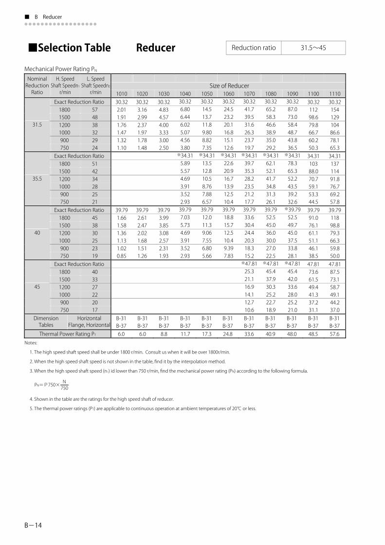
■Selection Table Reducer Reduction ratio 31.5~45
Mechanical Power Rating PN
Size of Reducer
31.5
35.5
40
45
DimensionTables
HorizontalFlange, Horizontal
Thermal Power Rating PT
Notes:
1. The high speed shaft speed shall be under 1800 r/min. Consult us when it will be over 1800r/min.
2. When the high speed shaft speed is not shown in the table, find it by the interpolation method.
3. When the high speed shaft speed (n1) id lower than 750 r/min, find the mechanical power rating (PN) according to the following formula.
PN=P750×N750
4. Shown in the table are the ratings for the high speed shaft of reducer.
5. The thermal power ratings (PT) are applicable to continuous operation at ambient temperatures of 20℃ or less.
101030.32
39.79
2.011.911.761.471.321.10
1.661.581.361.131.020.85
102030.323.162.992.371.971.781.48
39.792.612.472.021.681.511.26
103030.324.834.574.003.333.002.50
39.793.993.853.082.572.311.93
105030.3214.513.711.89.808.827.35※34.3113.512.810.58.767.886.5739.7912.011.39.067.556.805.66
106030.3224.523.220.116.815.112.6※34.3122.620.916.713.912.510.439.7918.815.712.510.49.397.83
Exact Reduction Ratio1800150012001000900750
Exact Reduction Ratio1800150012001000900750
Exact Reduction Ratio1800150012001000900750
Exact Reduction Ratio1800150012001000900750
108030.3265.258.346.638.935.029.2※34.3162.152.141.734.831.326.139.7952.545.036.030.027.022.5※47.8145.437.930.325.222.718.9
109030.3287.073.058.448.743.836.5※34.3178.365.352.243.539.232.6※39.7952.549.745.037.533.828.1※47.8145.442.033.628.025.221.0
110030.3211298.679.866.760.250.334.3110388.070.759.153.344.539.7991.076.161.151.146.138.5
73.661.549.441.337.231.1
47.81
1110
10486.678.165.334.3113711491.876.769.257.839.7911898.879.366.359.850.0
87.573.158.749.144.237.0
30.32154129
47.81
107030.3241.739.531.626.323.719.7※34.3139.735.328.223.521.217.739.7933.630.424.420.318.315.2※47.81
B-31 B-31 B-31 B-31 B-31 B-31 B-31 B-31 B-31 B-31 B-31 B-37 B-37 B-37 B-37 B-37 B-37 B-37 B-37 B-37 B-37 B-37 6.0 6.0 8.8 11.7 17.3 24.8 33.6 40.9 48.0 48.5 57.6
25.321.116.914.112.710.6
104030.326.806.446.025.074.563.80※34.31
39.797.035.734.693.913.522.93
5.895.574.693.913.522.93
574838322924
514234282521
453830252319
403327222017
NominalReductionRatio
H. SpeedShaft Speedn1r/min
L. SpeedShaft Speedn2r/min
DP1000ENG.indd 24DP1000ENG.indd 24 15/05/14 10:5415/05/14 10:54

B-15
B Reducer ■●●●●●●●●●●●●●●●●●●
Unit: kW
Size of Reducer
※Those reduction ratios will be available as option. We, however, recommend standard reduction ratio considering extra cost and
delivery date.
1120 1130 1140 1150 1160 1170 1180 1185 1190 1195 1200 1205 1210 1215 1220 30.32 30.32 30.32 200 241 296 172 212 260 138 182 222 115 160 196 104 145 182 87.0 121 159 34.31 34.31 34.31 182 219 271 152 192 239 122 165 204 102 142 180 92.2 128 167 77.0 107 141 39.79 39.79 39.79 157 194 244 132 171 215 106 146 184 88.4 123 162 79.7 111 146 66.6 92.5 122 47.81 47.81 47.81 131 171 213 110 151 178 88.3 123 143 73.8 102 119 66.5 92.4 108 55.6 77.2 90.0 B-31 B-31 B-31 B-37 B-37 B-37 70.5 84.1 101
DP1000ENG.indd 25DP1000ENG.indd 25 15/05/14 10:5415/05/14 10:54

■ B Reducer●●●●●●●●●●●●●●●●●●
B-16
Reduction ratio 50~90
Mechanical Power Rating PN
Size of Reducer
DimensionTables
Horizontal Flange, Horizontal
Thermal Power Rating PTNotes: 1. The high speed shaft speed shall be under 1800 r/min. Consult us when it will be over 1800r/min. 2. When the high speed shaft speed is not shown in the table, find it by the interpolation method. 3. When the high speed shaft speed (n1) id lower than 750 r/min, find the mechanical power rating (PN) according to the following formula.
4. Shown in the table are the ratings for the high speed shaft of reducer. 5. The thermal power ratings (PT) are applicable to continuous operation at ambient temperatures of 20℃ or less.
■Selection Table Reducer
PN=P750×N750
NominalReductionRatio
H. Speed Shaft Speedn1r/min
L. SpeedShaft Speedn2r/min
50
56
63
71
80
90
Exact Reduction Ratio1800150012001000900750
Exact Reduction Ratio1800150012001000900750
Exact Reduction Ratio1800150012001000900750
Exact Reduction Ratio1800150012001000900750
Exact Reduction Ratio1800150012001000900750
Exact Reduction Ratio1800150012001000900750
363024201815
322721181613
292419161412
252117141311
23191513119.4
20171311108.3
101051.741.411.341.080.900.810.68
68.481.161.030.830.690.620.52
90.630.950.790.630.530.470.39B-32B-384.1
102051.742.152.011.601.341.201.00
68.481.821.531.231.020.920.77
90.631.411.170.940.780.700.59B-32B-384.1
103051.743.393.062.452.041.841.53
68.482.792.341.871.561.401.17
90.632.151.791.431.191.070.89B-32B-385.9
104051.744.884.153.252.712.442.03
68.484.283.722.852.372.141.78
90.633.272.722.181.811.631.36B-32B-387.7
105051.749.688.606.885.735.164.30※58.519.227.816.255.214.693.91※62.978.727.485.994.994.493.7468.488.266.885.504.594.133.44※83.346.865.724.583.813.432.8690.636.315.264.213.513.162.63B-32B-3811.5
106051.7417.215.312.210.29.187.65※58.5115.913.510.89.008.106.75※62.9715.112.810.28.537.686.4068.4814.111.89.417.847.065.88※83.349.537.946.355.304.773.9790.639.537.946.355.304.773.97B-32B-3816.5
107051.7429.024.219.416.114.512.1※58.5125.721.417.114.312.810.7※62.9724.120.116.113.412.110.168.4822.218.514.812.311.19.24※83.3418.415.412.310.29.227.6890.6317.014.111.39.428.487.07B-32B-3822.4
108051.7442.935.728.623.821.417.9※58.5137.931.625.321.119.015.8※62.9735.629.723.819.817.814.868.4832.830.821.818.216.413.7※83.3427.222.718.215.113.611.390.6325.020.916.713.912.510.4B-32B-3827.2
1100
81.6945.939.031.226.023.419.5※92.3942.437.731.226.023.419.5※99.4340.335.930.025.022.518.7B-33B-3932.2
1110
※87.07
※93.71
76.9973.561.249.040.836.730.6
67.656.345.137.533.828.2
62.852.341.934.931.426.2B-33B-3936.3
109051.7453.744.735.829.826.822.4※58.5147.539.631.626.423.719.8※62.9744.637.229.724.822.318.668.4841.0
27.322.820.517.1※83.3434.128.422.718.917.014.290.6331.426.120.917.415.713.1B-32B-3832.0
34.2
DP1000ENG.indd 26DP1000ENG.indd 26 15/05/14 10:5415/05/14 10:54

B-17
B Reducer ■●●●●●●●●●●●●●●●●●●
Size of Reducer
※Those reduction ratios will be available as option. We, however, recommend standard reduction ratio considering extra cost and delivery date.
Unit: kW
1120 1130 1140 1150 1160 1170 1180 1185 1190 1195 1200 1205 1210 1215 1220
76.99 76.99 ※76.99 73.49 73.49 102 137 171 222 299 84.9 114 143 195 263 67.9 91.7 114 167 222 56.6 76.4 95.0 140 186 51.0 68.8 85.7 127 167 42.5 57.3 71.4 106 140 ※87.07 ※87.07 ※87.07 83.12 83.12 82.88 79.37 79.37 80.38 85.58 90.1 115 152 204 274 300 421 459 594 1586 75.1 101 126 179 241 264 370 404 523 1396 60.1 81.1 101 149 197 226 313 345 447 1147 50.1 67.6 84.2 124 164 199 261 304 394 956 45.1 60.8 75.8 112 148 185 235 282 366 860 37.5 50.7 63.1 93.7 124 158 196 249 322 717 ※93.71 ※93.71 93.71 89.45 91.25 92.28 89.77 85.10 89.77 91.14 86.28 92.47 88.90 99.41 83.7 107 141 194 257 275 386 421 421 536 798 1147 1223 1428 69.8 89.0 117 170 223 242 340 370 371 472 702 989 1076 1234 55.8 71.2 94.0 138 179 207 277 317 317 404 601 792 921 987 46.5 59.4 78.2 116 150 182 231 279 279 355 518 660 789 823 41.9 53.4 70.4 104 135 170 208 259 259 334 466 594 711 740 34.9 44.5 58.7 87.1 113 142 173 220 228 294 389 495 595 617 B-33 B-33 B-33 B-39 B-39 B-39 B-39 B-39 B-39 B-39 B-39 B-39 B-39 B-39 B-39 B-39 B-39 B-39 43.5 52.4 64.4 74.8 91.8 103 114 123 145 158 181 221 252 275
DP1000ENG.indd 27DP1000ENG.indd 27 15/05/14 10:5415/05/14 10:54

■ B Reducer●●●●●●●●●●●●●●●●●●
B-18
Reduction ratio 100~180
Mechanical Power Rating PN
100
112
125
140
160
180
Notes: 1. The high speed shaft speed shall be under 1800 r/min. Consult us when it will be over 1800r/min. 2. When the high speed shaft speed is not shown in the table, find it by the interpolation method. 3. When the high speed shaft speed (n1) id lower than 750 r/min, find the mechanical power rating (PN) according to the following formula.
4. Shown in the table are the ratings for the high speed shaft of reducer. 5. The thermal power ratings (PT) are applicable to continuous operation at ambient temperatures of 20℃ or less.
■Selection Table Reducer
NominalReductionRatio
H. Speed Shaft Speedn1r/min
L. SpeedShaft Speedn2r/min
DimensionTables
Horizontal Flange, Horizontal
Thermal Power Rating PT
PN=P750×N750
Size of Reducer
Exact Reduction Ratio
Exact Reduction Ratio
Exact Reduction Ratio
Exact Reduction Ratio
Exact Reduction Ratio
Exact Reduction Ratio
128.40.680.560.450.380.340.28
1800150012001000900750
1800150012001000900750
1800150012001000900750
1800150012001000900750
1800150012001000900750
181.91800 0.481500 0.401200 0.321000 0.27900 0.24750 0.20
181512109.07.5
1613118.98.06.7
14129.68.07.26.0
13118.67.16.45.4
119.47.56.35.64.7
108.36.75.65.04.2
B-32B-384.1
1010
128.41.000.840.670.560.500.42
181.90.720.600.480.400.360.30B-32B-384.1
1020
128.41.531.281.020.850.770.64
181.91.090.910.730.610.550.46B-32B-385.9
1030
128.42.331.941.551.291.170.97
181.91.661.391.110.920.830.69B-32B-387.7
1040※97.014.773.973.182.652.381.99※109.74.773.973.182.652.381.99128.44.513.753.002.502.251.88※145.33.633.022.422.021.811.51※168.53.472.892.311.931.741.45181.93.222.682.141.791.611.34B-32B-3811.5
1050※97.019.537.946.355.304.773.97※109.79.027.516.015.014.513.76128.47.706.425.144.283.853.21※145.36.885.744.593.823.442.87※168.55.944.953.963.302.972.47181.95.504.583.673.062.752.29B-32B-3816.5
1060※97.0115.813.210.68.807.926.60※109.714.211.89.457.877.085.90128.412.110.18.076.726.055.04※145.39.537.946.355.304.773.97※168.59.337.776.225.184.663.89181.98.647.205.764.804.323.60B-32B-3822.4
1070※97.0123.419.515.613.011.79.75※109.720.917.413.911.610.58.72128.417.914.911.99.938.947.45※145.316.013.310.68.877.996.66※168.513.811.59.187.656.895.74181.912.810.68.517.096.385.32B-32B-3827.2
1080※97.0129.324.419.516.314.612.2※109.726.221.817.514.613.110.9128.422.418.714.912.411.29.33※145.320.016.713.311.110.08.33※168.517.214.411.59.588.627.19181.916.013.310.78.887.996.66B-32B-3832.0
1090108.137.733.827.623.020.717.2※125.832.926.722.018.316.513.7※137.932.027.321.818.216.413.6153.229.524.519.616.414.712.3※173.324.620.516.413.612.310.2201.018.415.312.310.29.207.67B-33B-3932.2
1100101.957.748.138.532.128.924.1※118.6
※129.9
49.641.433.127.624.820.7
45.337.730.225.222.618.9144.440.834.027.222.620.417.0※163.436.030.024.020.018.015.0189.531.125.920.717.315.512.9B-33B-3936.3
1110
DP1000ENG.indd 28DP1000ENG.indd 28 15/05/14 10:5415/05/14 10:54

B-19
B Reducer ■●●●●●●●●●●●●●●●●●●
Unit: kW
Size of Reducer
※Those reduction ratios will be available as option. We, however, recommend standard reduction ratio considering extra cost and
delivery date.
101.9 101.9 109.4 104.5 104.5 105.2 98.54 96.24 98.54 98.21 96.12 97.40 103.6 99.14 105.5 77.0 88.5 133 174 234 291 339 386 394 504 740 770 1058 1133 1370 64.2 73.7 111 148 196 249 299 340 347 443 651 677 884 997 1162 51.3 59.0 88.5 119 157 199 252 291 297 379 557 579 707 848 930 42.8 49.2 73.7 99.3 131 166 210 256 261 334 465 510 590 709 775 38.5 44.2 66.4 89.5 118 149 189 229 243 310 419 462 531 639 697 32.1 36.9 55.3 74.8 98.8 124 158 195 214 273 349 386 442 534 581 ※118.6 ※112.3 118.6 113.2 113.2 113.7 112.8 105.7 112.8 112.1 109.5 109.6 110.6 111.0 121.3 66.2 93.4 122 164 216 273 303 339 359 518 675 708 992 1047 1214 55.1 77.9 102 137 181 230 267 299 316 456 594 623 828 921 1011 44.1 62.3 81.6 110 145 184 220 255 270 390 490 533 663 759 809 36.8 51.9 68.0 91.7 121 153 184 225 238 340 408 456 552 634 674 33.1 46.7 61.2 82.7 109 138 165 209 221 306 367 411 497 572 607 27.6 38.9 51.0 69.1 91.3 115 138 178 194 255 306 343 414 478 506 ※129.9 ※125.9 129.9 124.0 124.0 124.1 122.2 121.0 122.2 121.3 118.3 126.8 118.9 127.5 131.7 60.4 84.2 112 150 198 253 284 303 339 490 640 640 924 950 1118 50.3 70.1 93.1 125 165 211 250 267 299 432 563 563 770 824 931 40.3 56.1 74.5 100 133 169 203 228 255 369 454 473 616 662 745 33.5 46.8 62.1 83.8 111 141 169 201 225 315 378 395 513 553 621 30.2 42.1 55.9 75.5 99.9 127 153 186 209 283 340 356 462 499 559 25.2 35.1 46.6 63.1 83.4 105 127 155 184 236 283 297 385 417 466 144.4 144.4 144.4 137.8 137.8 137.2 133.9 143.6 133.9 146.7 142.3 138.2 141.7 138.4 144.6 54.4 73.4 101 135 178 229 263 263 318 429 562 602 776 897 1018 45.3 61.1 83.8 113 149 191 232 232 280 378 471 530 646 761 848 36.2 48.9 67.1 90.4 120 153 186 198 240 312 377 434 517 611 679 30.2 40.8 55.9 75.5 99.9 127 155 174 211 260 314 363 431 510 566 27.2 36.7 50.3 68.1 90.0 114 139 157 196 234 283 327 388 460 509 22.6 30.6 41.9 56.9 75.2 95.4 116 131 171 195 236 272 323 384 424 ※163.4 ※163.4 163.4 155.9 155.9 154.3 148.8 159.6 148.8 165.1 159.4 152.5 157.7 151.9 161.0 48.0 64.8 88.9 119 158 204 241 241 296 395 505 562 697 830 914 40.0 54.0 74.1 99.8 132 170 209 212 260 347 421 491 581 694 762 32.0 43.2 59.3 80.1 106 136 167 182 222 277 337 394 464 557 609 26.7 36.0 49.4 66.9 88.4 113 139 157 196 231 280 329 387 466 508 24.0 32.4 44.5 60.3 79.7 102 125 141 182 208 252 296 348 420 457 20.0 27.0 37.0 50.3 66.5 84.8 104 118 154 173 210 247 290 351 381 189.5 ※189.5 189.5 180.9 180.9 177.4 168.4 180.6 168.4 190.0 182.2 170.9 178.8 169.1 182.6 41.4 55.9 76.6 103 136 177 219 219 271 358 442 519 615 747 806 34.5 46.6 63.9 86.2 114 148 185 192 239 301 368 439 512 625 672 27.6 37.3 51.1 69.2 91.4 118 148 165 204 241 294 352 410 501 537 23.0 31.1 42.6 57.8 76.3 98.3 123 139 180 201 245 293 341 419 448 20.7 28.0 38.3 52.0 68.8 88.5 111 125 163 181 221 264 307 378 403 17.3 23.3 31.9 43.5 57.5 73.8 92.3 104 136 151 184 220 256 316 336 B-33 B-33 B-33 B-39 B-39 B-39 B-39 B-39 B-39 B-39 B-39 B-39 B-39 B-39 B-39 B-39 B-39 B-39 43.5 52.4 64.4 74.8 91.8 103 114 123 145 158 181 187 221 252 275
1120 1130 1140 1150 1160 1170 1180 1185 1190 1195 1200 1205 1210 1215 1220
DP1000ENG.indd 29DP1000ENG.indd 29 15/05/14 10:5415/05/14 10:54

■ B Reducer●●●●●●●●●●●●●●●●●●
B-20
Reduction ratio 200~224
Mechanical Power Rating PN
Size of ReducerH. Speed
r/min
L. Speed Shaft Speedn2r/min
Exact Reduction Ratio ※205.8 ※205.8 ※205.8 ※205.8 ※205.89.0 2.87 4.91 7.18 11.4 14.17.5 2.39 4.10 5.98 9.50 11.86.0 1.92 3.28 4.79 7.60 9.435.0 1.60 2.73 3.99 6.34 7.864.5 1.44 2.46 3.59 5.70 7.07
200
3.8 1.20 2.05 2.99 4.75 5.90Exact Reduction Ratio 238.7 238.7 238.7 238.7 238.7 238.7 238.7 238.7 238.7
8.0 0.37 0.55 0.84 1.28 2.48 4.24 6.66 9.83 12.36.7 0.31 0.46 0.70 1.07 2.06 3.53 5.85 8.19 10.35.4 0.25 0.37 0.56 0.85 1.65 2.82 4.44 6.55 8.214.5 0.21 0.31 0.47 0.71 1.38 2.35 3.70 5.46 6.844.0 0.19 0.28 0.42 0.64 1.24 2.12 3.33 4.92 6.16
224
3.3 0.15 0.23 0.35 0.53 1.03 1.77 2.77 4.10 5.13B-32 B-32 B-32 B-32 B-32 B-32 B-32 B-32 B-32Dimension
TablesHorizontal
Flange, Horizontal B-38 B-38 B-38 B-38 B-38 B-38 B-38 B-38 B-38Thermal Power Rating PT 4.1 4.1 5.9 7.7 11.5 16.5 22.4 27.2 32.0
Notes:
1. The high speed shaft speed shall be under 1800 r/min. Consult us when it will be over 1800r/min.
2. When the high speed shaft speed is not shown in the table, find it by the interpolation method.
3. When the high speed shaft speed (n1) id lower than 750 r/min, find the mechanical power rating (PN) according to the following formula.
4. Shown in the table are the ratings for the high speed shaft of reducer.
5. The thermal power ratings (PT) are applicable to continuous operation at ambient temperatures of 20℃ or less.
NominalReductionRatio
Shaft Speedn1
1800150012001000900750
1800150012001000900750
1010 1020 1030 1040 1050 1060 1070 1080 1090 1100 1110※227.724.820.716.613.812.410.3
B-33B-3936.3
PN=P750×N750
■Selection Table Reducer
DP1000ENG.indd 30DP1000ENG.indd 30 15/05/14 10:5415/05/14 10:54

B-21
B Reducer ■●●●●●●●●●●●●●●●●●●
Unit: kW
Size of Reducer
※227.7 ※227.7 227.7 217.3 217.3 210.4 195.3 195.3209.4 207.9 212.434.5 40.6 63.8 86.1 114 149 191 244194 529 69328.7 53.233.8 71.9 95.0 124 159 215171 441 57823.0 42.527.0 57.7 76.3 99.5 127 184 352 46219.1 22.5 35.4 48.2 63.7 82.9 106 156 294 38517.2 20.2 31.9 43.4 57.4 74.6 95.4 141
144120108 264 347
14.4 16.8 26.6 36.2 47.9 62.2 79.5 11789.8 220
195.4460385308257231193 289
234.7 255.8575479384320288240
B-33 B-33B-39 B-39 B-39 B-39 B-39 B-39 B-39 B-39B-39 B-39 B-39 B-3943.5 52.4 64.4 74.8 91.8 103 114 145123 181 221
B-39187 275
191.7660552443370334279222.8570476382319288240
B-39252
※Those reduction ratios will be available as option. We, however, recommend standard reduction ratio considering extra cost and
delivery date.
234.7159 215132 185106 14888.3 12479.4 11166.2 92.7
1120 1130 1140 1150 1160 1170 1180 1185 1190 1195 1200 1205 1210 1215 1220214.2376313250209188157
250.3439366293244220183
DP1000ENG.indd 31DP1000ENG.indd 31 15/05/14 10:5415/05/14 10:54

■ B Reducer●●●●●●●●●●●●●●●●●●
B-22
Reduction ratio 250~450
Mechanical Power Rating PN
Size of ReducerNominal Reduction Ratio 1010 1020 1030 1040 1050 1060 1070 1080 1090 1100 1110
261.41800 7.2 15.11500 6.0 13.01200 4.8 10.81000 4.0 9.3900 3.6 8.5750 3.0 7.3
246.424.420.316.313.612.210.2
※295.7 ※278.61800 6.4 13.71500 5.4 11.81200 4.3 9.81000 3.6 8.4900 3.2 7.7750 2.7 6.4
21.618.014.412.010.89.0
310.4 310.4 310.4 310.4 310.4 310.4 310.4 310.4 310.4 346.01800 5.7 0.30 0.44 0.67 1.02 1.97 3.37 5.27 7.81 9.68 12.01500 4.8 0.25 0.37 0.56 0.85 1.64 2.80 4.41 6.51 8.15 10.31200 3.8 0.20 0.29 0.45 0.68 1.31 2.24 3.53 5.21 6.52 8.61000 3.2 0.16 0.24 0.37 0.57 1.09 1.87 2.94 4.34 5.43 7.3900 2.9 0.15 0.22 0.33 0.51 0.98 1.68 2.64 3.91 4.89 6.6750 2.4 0.12 0.18 0.28 0.42 0.82 1.40 2.20 3.25 4.07 5.5
326.118.415.412.310.29.27.7
※351.1 ※351.1 ※391.3 ※368.81800 5.1 6.98 8.74 9.3 16.31500 4.2 5.82 7.28 7.8 13.61200 3.4 4.65 5.83 6.2 10.91000 2.8 3.88 4.86 5.2 9.1900 2.5 3.49 4.37 4.7 8.2750 2.1 2.91 3.64 3.9 6.8
410.9 410.9 410.9 410.9 410.9 410.9 410.9 410.9 ※421.1 ※396.91800 4.5 0.22 0.33 0.51 0.77 1.49 2.56 4.02 7.43 9.3 15.21500 3.8 0.19 0.28 0.42 0.64 1.25 2.13 3.35 6.19 7.8 12.61200 3.0 0.15 0.22 0.34 0.52 1.00 1.70 2.68 4.95 6.2 10.11000 2.5 0.12 0.19 0.28 0.43 0.83 1.42 2.23 4.13 5.2 8.4900 2.3 0.11 0.17 0.25 0.39 0.75 1.28 2.01 3.71 4.7 7.6750 1.9 0.09 0.14 0.21 0.32 0.62 1.07 1.67 3.09 3.9 6.3
※464.7 ※464.7 457.9 462.01800 4.0 4.87 6.67 9.3 13.01500 3.3 4.06 5.56 7.8 10.81200 2.7 3.25 4.45 6.2 8.71000 2.2 2.71 3.71 5.2 7.2900 2.0 2.43 3.34 4.7 6.5
250
280
315
355
400
450
750 1.7 2.03 2.78 3.9 5.4B-34 B-34 B-34 B-34 B-34 B-34 B-34 B-34 B-34 B-35 B-35Dimension
TablesHorizontal
Flange, Horizontal B-40 B-40 B-40 B-40 B-40 B-40 B-40 B-40 B-40 B-41 B-41Thermal Power Rating PT 3.0 3.0 4.3 5.8 8.7 12.3 16.8 20.4 24.4 24.7 28.3
Notes: 1. The high speed shaft speed shall be under 1800 r/min. Consult us when it will be over 1800r/min. 2. When the high speed shaft speed is not shown in the table, find it by the interpolation method. 3. When the high speed shaft speed (n1) id lower than 750 r/min, find the mechanical power rating (PN) according to the following formula.
4. Shown in the table are the ratings for the high speed shaft of reducer. 5. The thermal power ratings (PT) are applicable to continuous operation at ambient temperatures of 20℃ or less.
H. Speed Shaft Speedn1r/min
L. Speed Shaft Speedn2r/min
Exact Reduction Ratio
Exact Reduction Ratio
Exact Reduction Ratio
Exact Reduction Ratio
Exact Reduction Ratio
Exact Reduction Ratio
410.95.934.943.953.302.972.47
PN=P750×N750
■Selection Table Reducer
DP1000ENG.indd 32DP1000ENG.indd 32 15/05/14 10:5415/05/14 10:54

B-23
B Reducer ■●●●●●●●●●●●●●●●●●●
Unit: kW
Size of Reducer1120 1130 1140 1150 1160 1170 1180 1185 1190 1195 1200 1205 1210 1215 1220246.4 246.432.5 43.927.1 36.621.7 29.318.1 24.416.3 22.013.6 18.3※278.6 ※278.628.8 38.824.0 32.419.2 25.916.0 21.614.4 19.412.0 16.2326.124.6 33.220.5 27.716.4 22.113.7 18.412.3 16.610.2 13.8※368.8 371.321.7 29.418.1 24.514.5 19.612.1 16.310.9 14.79.1 12.2
228.0190.0151.9126.6113.994.9
51.8 68.5 83.543.3 57.2 69.734.7 45.9 55.929.0 38.3 46.726.1 34.5 42.021.8 28.8 35.1
389.0 420.0 420.0 427.5 401.0 401.0 386.8 408.0 386.8 389.6 417.8 389.6
462.0 462.0 ※440.0 452.0 452.0 460.0 453.6 430.0 453.6 437.5 447.9 437.5 440.7 472.5 440.7
B-35 B-35 B-35B-41 B-41 B-41 B-41 B-41 B-41 B-41 B-41 B-42 B-42 B-42 B-42 B-42 B-42 B-42
※Those reduction ratios will be available as option. We, however, recommend standard reduction ratio considering extra cost and delivery date.
326.1
※368.8 360.8
※396.9 ※396.920.2 27.3 38.1 45.9 60.6 73.9 95.0 140.0 181.4 201.0 238.4 288.0 313.3 386.016.8 22.7 31.8 38.3 50.6 61.7 79.1 117.0 151.2 168.0 198.7 240.0 261.7 322.013.5 18.2 25.4 30.7 40.6 49.5 63.3 93.3 120.9 134.3 158.9 192.1 210.0 257.211.2 15.2 21.2 25.6 33.9 41.3 52.8 77.8 100.8 111.9 132.4 160.1 175.4 214.410.1 13.6 19.1 23.1 30.5 37.2 47.5 70.0 90.7 100.7 119.2 144.1 158.0 192.9 8.4 11.4 15.9 19.3 25.5 31.1 39.6 58.3 75.6 83.9 99.3 120 131.9 160.8
17.4 23.4 33.7 42.7 56.4 68.7 84.0 92.4 124.0 160.4 183.0 210.8 255.0 277.5 341.014.5 19.5 28.1 35.6 47.1 57.4 70.0 79.6 103.0 133.7 152.9 175.7 212.0 231.8 284.011.6 15.6 22.5 28.6 37.8 46.0 56.0 66.3 82.5 106.9 122.3 140.5 169.8 185.9 227.5 9.6 13.0 18.7 23.8 31.5 38.4 46.7 57.1 68.8 89.1 101.9 117.1 141.5 155.3 189.5 8.7 11.7 16.9 21.5 28.4 34.6 42.0 52.4 61.9 80.2 91.7 105.4 127.4 139.9 170.6 7.2 9.8 14.0 17.9 23.7 28.9 35.0 44.7 51.6 66.8 76.5 87.8 106.1 116.7 142.2
371.3 378.0
34.4 41.3 49.3 59.7 71.4 77.5 87.2 92.6 113 122 143 147 173 174 212
DP1000ENG.indd 33DP1000ENG.indd 33 15/06/02 18:3315/06/02 18:33

■ B Reducer●●●●●●●●●●●●●●●●●●
B-24
Reduction ratio 500~900
Mechanical Power Rating PN
Size of ReducerNominal ReductionRatio
H. Speed Shaft Speedn1r/min
L. Speed Shaft Speedn2
1010 1020 1030 1040 1050 1060 1070 1080 1090 1100 1110※500.1 ※500.1 ※554.3 ※522.4
1800 3.6 4.87 6.20 8.11500 3.0 4.06 5.17 6.81200 2.4 3.25 4.13 5.51000 2.0 2.71 3.45 4.6900 1.8 2.43 3.10 4.1750 1.5 2.03 2.58 3.4
11.59.6 7.7 6.4 5.8 4.8
543.8 543.8 543.8 543.8 543.8 543.8 543.8 543.8 543.8 ※596.6 ※562.21800 3.2 1.15 1.96 3.08 4.56 5.70 7.61500 2.7 0.96 1.64 2.57 3.80 4.75 6.41200 2.1 0.77 1.31 2.06 3.04 3.80 5.11000 1.8 0.64 1.09 1.71 2.53 3.17 4.3900 1.6 0.57 0.98 1.54 2.28 2.85 3.8750 1.3
0.170.140.110.100.090.07
0.260.210.170.140.130.11
0.390.330.260.220.200.16
0.590.490.400.330.300.25 0.48 0.82 1.29 1.90 2.38 3.2
10.78.9 7.1 5.9 5.3 4.5
Exact Reduction Ratio ※658.3 ※658.3 648.71800 2.9 3.80 4.76 7.01500 2.4 3.17 3.97 5.91200 1.9 2.54 3.17 4.71000 1.6 2.11 2.65 3.9900 1.4 1.90 2.38 3.5750 1.2 1.58 1.98 2.9
9.8 8.2 6.6 5.5 4.9 4.1
Exact Reduction Ratio ※708.4 ※708.4 ※734.1 ※691.91800 2.5 3.531500 2.1 2.941200 1.7 2.361000 1.4 1.96900 1.3 1.77750 1.1 1.47
4.423.692.952.462.211.84
8.7 7.2 5.8 4.8 4.3 3.6
6.25.24.13.53.12.6
Exact Reduction Ratio 770.4 770.4 770.4 770.4 770.4 770.4 770.4 770.4 770.4 851.51800 2.3 2.21 3.27 4.09 5.31500 1.9 1.84 2.72 3.41 4.51200 1.5 1.47 2.18 2.73 3.61000 1.3 1.23 1.81 2.27 3.0900 1.1 1.11 1.63 2.04 2.7750 0.9
0.120.100.080.070.060.05
1.411.170.940.780.700.59
0.820.690.550.460.410.34
0.430.350.280.240.210.18
0.280.230.190.160.140.12
0.180.150.120.100.090.08 0.92 1.36 1.70 2.2
7.56.25.04.23.73.1
Exact Reduction Ratio ※871.7 ※871.7 919.01800 2.0 2.90 3.63 5.01500 1.7 2.42 3.03 4.11200 1.3 1.93 2.42 3.31000 1.1 1.61 2.02 2.8900 1.0 1.45 1.82 2.5
500
560
630
710
800
900
750 0.8 1.21 1.51 2.1
6.9 5.8 4.6 3.9 3.5 2.9
B-34 B-34 B-34 B-34 B-34 B-34 B-34 B-34 B-34 B-35 B-35Dimension Tables
Horizontal Flange, Horizontal B-40 B-40 B-40 B-40 B-40 B-40 B-40 B-40 B-40
Thermal Power Rating PT 3.0 3.0 4.3 5.8 8.7 12.3 16.8 20.4 24.4 24.7Notes: 1. The high speed shaft speed shall be under 1800 r/min. Consult us when it will be over 1800r/min. 2. When the high speed shaft speed is not shown in the table, find it by the interpolation method. 3. When the high speed shaft speed (n1) id lower than 750 r/min, find the mechanical power rating (PN) according to the following formula.
4. Shown in the table are the ratings for the high speed shaft of reducer. 5. The thermal power ratings (PT) are applicable to continuous operation at ambient temperatures of 20℃ or less.
Exact Reduction Ratio
Exact Reduction Ratio
r/min
PN=P750×N750
611.4
28.3B-41B-41
802.5
866.2
■Selection Table Reducer
DP1000ENG.indd 34DP1000ENG.indd 34 15/05/14 10:5415/05/14 10:54

B-25
B Reducer ■●●●●●●●●●●●●●●●●●●
Unit: kW
Size of Reducer1120 1130 1140 1150 1160 1170 1180 1185 1190 1195 1200 1205 1210 1215 1220
※Those reduction ratios will be available as option. We, however, recommend standard reduction ratio considering extra cost and delivery date.
※522.4 ※522.4 ※473.5 491.5 491.5 500.2 488.1 486.3 488.1 470.8 512.8 480.2 483.8 518.7 483.8 15.3 20.7 31.3 39.3 51.9 63.3 78.0 83.6 115.0 149.0 160.3 192.0 232.0 253.1 311.0 12.8 17.3 26.1 32.8 43.3 52.8 65.0 72.0 95.8 124.2 133.6 160.0 193.4 211.4 259.0 10.2 13.8 20.9 26.3 34.7 42.4 52.0 60.0 76.7 99.4 106.8 128.0 154.7 169.6 207.2 8.5 11.5 17.4 21.9 29.0 35.4 43.4 51.7 63.9 82.8 89.0 106.7 128.9 141.6 172.7 7.7 10.4 15.7 19.8 26.1 31.9 39.0 47.4 57.5 74.5 80.1 96.0 116.0 127.5 155.4 6.4 8.6 13.1 16.5 21.8 26.6 32.5 39.5 47.9 62.1 66.8 80.0 96.7 106.3 129.5 ※562.2 ※562.2 514.9 571.9 571.9 551.2 530.8 569.1 570.0 549.8 555.7 549.8 553.8 593.8 553.8 14.3 19.3 28.8 33.8 44.7 57.5 71.8 73.5 98.5 127.6 147.9 167.7 202.7 221.4 271.5 11.9 16.0 24.0 28.2 37.3 48.0 59.8 63.3 82.1 106.3 123.3 139.8 168.9 184.9 226.2 9.5 12.8 19.2 22.6 29.9 38.5 47.8 52.7 65.6 85.1 98.6 111.8 135.1 148.3 181.0 7.9 10.7 16.0 18.9 25.0 32.1 39.9 45.0 54.7 70.9 82.2 93.2 112.6 123.8 150.8 7.1 9.6 14.4 17.0 22.5 28.9 35.9 40.5 49.2 63.8 74.0 83.9 101.3 111.4 135.7 5.9 8.0 12.0 14.2 18.8 24.1 29.9 33.8 41.0 53.2 61.6 69.9 84.5 92.8 113.1 611.4 611.4 ※599.2 626.6 626.6 617.8 584.8 627.0 617.7 652.7 608.8 652.7 600.1 643.4 600.1 13.1 17.7 24.8 30.9 40.8 51.3 65.1 67.9 90.9 107.7 135.0 141.3 187.1 204.6 250.5 10.9 14.8 20.6 25.8 34.1 42.9 54.3 58.5 75.7 89.6 112.5 117.7 155.9 170.8 208.8 8.7 11.8 16.5 20.7 27.3 34.4 43.4 48.7 60.6 71.7 90.0 94.2 124.7 137.0 167.0 7.3 9.8 13.8 17.2 22.8 28.7 36.2 40.9 50.5 59.7 75.0 78.5 103.9 114.2 139.2 6.6 8.9 12.4 15.5 20.5 25.8 32.6 36.8 45.4 53.7 67.5 70.6 93.5 102.8 125.3 5.5 7.4 10.3 12.9 17.1 21.6 27.1 30.6 37.9 44.8 56.2 58.9 77.9 85.7 104.4 ※691.9 ※691.9 ※656.5 696.2 696.2 708.7 655.5 702.8 676.8 725.3 676.5 725.3 657.5 705.0 657.5 11.6 15.6 22.6 27.8 36.8 44.8 58.1 61.8 82.9 96.7 121.5 127.1 170.7 186.9 228.7 9.7 13.0 18.8 23.2 30.7 37.4 48.4 53.2 69.1 80.6 101.2 106.0 142.3 156.1 190.5 7.7 10.4 15.1 18.6 24.6 30.0 38.7 43.7 55.3 64.5 81.0 84.8 113.8 125.1 152.4 6.4 8.7 12.6 15.5 20.5 25.0 32.3 36.4 46.1 53.7 67.5 70.6 94.8 104.3 127.0 5.8 7.8 11.3 14.0 18.5 22.5 29.1 32.8 41.5 48.4 60.7 63.6 85.4 93.8 114.3 4.8 6.5 9.4 11.6 15.4 18.8 24.2 27.3 34.6 40.3 50.6 53.0 71.1 78.2 95.3 802.5 ※802.5 729.4 787.9 787.9 801.9 751.9 806.2 751.9 820.7 765.5 820.7 730.6 783.3 730.6 10.0 13.5 20.3 24.6 32.5 39.7 50.7 55.3 74.6 85.5 107.4 112.4 153.7 168.4 205.8 8.3 11.2 16.9 20.5 27.2 33.1 42.2 47.6 62.2 71.2 89.5 93.6 128.0 140.6 171.5 6.7 9.0 13.6 16.5 21.8 26.5 33.8 38.1 49.8 57.0 71.6 74.9 102.4 112.6 137.2 5.6 7.5 11.3 13.7 18.2 22.1 28.1 31.8 41.5 47.5 59.7 62.4 85.4 93.8 114.3 5.0 6.7 10.2 12.3 16.4 19.9 25.3 28.6 37.3 42.7 53.7 56.2 76.8 84.5 102.9 4.2 5.6 8.5 10.3 13.6 16.6 21.1 23.8 31.1 35.6 44.7 46.8 64.0 70.4 85.7 866.2 866.2 ※825.4 913.8 913.8 930.1 850.9 912.3 850.9 887.9 826.7 886.3 826.7 9.3 12.5 18.0 21.2 28.1 34.2 44.8 49.9 66.0 92.6 135.8 149.0 181.9 7.7 10.4 15.0 17.7 23.4 28.6 37.3 42.1 55.0 77.1 113.2 124.4 151.6 6.2 8.3 12.0 14.2 18.8 22.9 29.8 33.7 44.0 61.7 90.5 99.5 121.2 5.1 6.9 10.0 11.8 15.7 19.1 24.9 28.1 36.6 51.4 75.4 82.9 101.0 4.6 6.2 9.0 10.6 14.1 17.2 22.4 25.3 33.0 46.3 67.9 74.6 90.9 3.9 5.2 7.5 8.9 11.8 14.4 18.7 21.1 27.5 38.6 56.6 62.2 75.8 B-35 B-35 B-35 B-41 B-41 B-41 B-41 B-41 B-41 B-41 B-41 B-42 B-42 B-42 B-42 B-42 B-42 B-42 34.4 41.3 49.3 59.7 71.4 77.5 87.2 92.6 113 122 143 147 173 174 212
DP1000ENG.indd 35DP1000ENG.indd 35 15/05/14 10:5415/05/14 10:54

■ B Reducer●●●●●●●●●●●●●●●●●●
B-26
Reduction ratio 1000~1400
Mechanical Power Rating PN
Size of ReducerNominal
Ratio
L. SpeedShaft Speedn2r/min
Exact Reduction Ratio
1000
Exact Reduction Ratio
1120
Exact Reduction Ratio
1250
Exact Reduction Ratio
1400
DimensionTables
HorizontalFlange, Horizontal
Thermal Power Rating PTNotes:
1. The high speed shaft speed shall be under 1800 r/min. Consult us when it will be over 1800r/min.
2. When the high speed shaft speed is not shown in the table, find it by the interpolation method.
3. When the high speed shaft speed (n1) id lower than 750 r/min, find the mechanical power rating (PN) according to the following formula.
4. Shown in the table are the ratings for the high speed shaft of reducer.
5. The thermal power ratings (PT) are applicable to continuous operation at ambient temperatures of 20℃ or less.
ReductionH. Speed
Shaft Speedn1r/min
1800150012001000900750
1800150012001000900750
1800150012001000900750
1800150012001000900750
1.81.51.21.00.90.8
1.61.31.10.90.80.7
1.41.21.00.80.70.6
1.31.10.90.70.60.5
1010 1020 1030 1040 1050 1060 1070 1080 1090 1100 1110※1011 ※1011 ※1040 ※980.12.50 3.13 6.12.09 2.61 5.11.67 2.09 4.11.39 1.74 3.41.25 1.57 3.11.04 1.31 2.6
1091 1091 1091 1091 1091 1091 1091 1091 1091 11370.59 1.01 1.59 2.34 2.93 5.30.49 0.84 1.32 1.95 2.44 4.40.39 0.67 1.06 1.56 1.96 3.50.33 0.56 0.88 1.30 1.63 2.90.30 0.50 0.79 1.17 1.47 2.6
0.090.070.060.050.040.04
0.130.110.090.070.060.05
0.200.170.130.110.100.08
0.310.250.200.170.150.13 0.25 0.42 0.66 0.98 1.22 2.2
4.43.72.92.42.21.812063.83.22.52.11.91.6
※1235 ※12352.09 2.621.74 2.181.39 1.751.16 1.451.05 1.310.87 1.09
1432 1432 1432 1432 1432 1432 1432 1432 14321.82 2.281.521.211.010.91
0.070.050.040.040.030.03
0.100.080.070.050.050.04
0.150.130.100.080.080.06
0.230.200.160.130.120.10
0.460.380.310.250.230.19
0.820.650.520.440.390.33
1.231.030.820.690.620.51 0.76
B-34 B-34 B-34 B-34 B-34 B-34 B-34 B-34 B-34 B-35B-40 B-40 B-40 B-40 B-40 B-40 B-40 B-40 B-40 B-41 B-413.0 3.0 4.3 5.8 8.7 12.3 16.8 20.4 24.4 28.3
B-35
24.7
1.901.521.271.140.95
■Selection Table Reducer
PN=P750×N750
DP1000ENG.indd 36DP1000ENG.indd 36 15/05/14 10:5415/05/14 10:54

B-27
B Reducer ■●●●●●●●●●●●●●●●●●●
Unit: kW
Size of Reducer1120 1130 1140 1150 1160 1170 1180 1185 1190 1195 1200 1205 1210 1215 1220
B-35 B-35 B-35B-41 B-41 B-41 B-41 B-41 B-41 B-41 B-41 B-42 B-42 B-42 B-42 B-42 B-42 B-4234.4 41.3 49.3 59.7 71.4 77.5 87.2 92.6 113 122 143 147 173 174 212※Those reduction ratios will be available as option. We, however, recommend standard reduction ratio considering extra cost and
delivery date.
※980.1 ※980.1 957.3 1098 1098 1118 987 1058 986.9 951.9 1067 951.9 958.9 1028 958.9 8.2 11.0 15.5 17.7 23.4 28.5 38.6 43.6 56.9 73.7 77.0 96.9 117.1 128.7 156.8 6.8 9.2 12.9 14.8 19.5 23.8 32.2 36.3 47.4 61.4 64.2 80.7 97.6 107.2 130.7 5.5 7.4 10.3 11.8 15.7 19.1 25.7 29.0 37.9 49.1 51.4 64.6 78.0 85.8 104.5 4.5 6.1 8.6 9.8 13.1 15.9 21.4 24.2 31.6 40.9 42.8 53.8 65.0 71.5 87.1 4.1 5.5 7.7 8.9 11.8 14.3 19.3 21.8 28.4 36.9 38.5 48.4 58.5 64.3 78.4 3.4 4.6 6.5 7.4 9.8 12.0 16.1 18.2 23.7 30.7 32.1 40.4 48.8 53.6 65.3 1137 1137 1186 1186 1144 1144 1152 1152 7.1 9.5 32.1 47.3 61.3 80.6 97.4 130.5 5.9 7.9 26.8 39.4 51.1 67.2 81.2 108.8 4.7 6.3 21.4 31.6 40.9 53.8 65.0 87.0 3.9 5.3 17.8 26.3 34.1 44.8 54.1 72.5 3.5 4.8 16.1 23.7 30.7 40.3 48.7 65.3 2.9 4.0 13.4 19.7 25.6 33.6 40.6 54.4
DP1000ENG.indd 37DP1000ENG.indd 37 15/05/14 10:5415/05/14 10:54

■ B Reducer●●●●●●●●●●●●●●●●●●
B-28
■Allowable Radial Loads on Low Speed ShaftAllowable Radial Load FrA [kN] Reduction Ratio 5~45
Size of Reducer Shaft Speed (r/min) 1010 1020 1030 1040 1050 1060 1070 1080 1090 1100 1110 1120 1130 1140
Allowable Radial Load FrA [kN] Reduction Ratio 50~1400
Size of Reducer Shaft Speed (r/min) 1010 1020 1030 1040 1050 1060 1070 1080 1090 1100 1110 1120 1130 1140 1150 1160
Overhang Factor K3 Overhang Member Overhang Factor
Sprocket (Single Row) 1 Sprocket (Double Row) 1.25
Gears 1.25 V-belt 1.5 Flat belt 2.5
Note: The value shown in the above table is allowable radial load when it is applied to the center of the shaft. Consult us when a load is not in the center.
100 5.0 5.4 6.7 8.9 11.7 18.0 23.6 47.5 48.5 92.6 112 132 148 184
60 5.9 6.4 7.9 10.5 13.9 21.3 28.0 56.2 69.4 108 131 154 173 214
40 6.8 7.3 9.0 12.0 16.0 24.4 32.1 64.4 79.4 122 148 174 195 242
20 8.4 9.2 11.3 15.2 21.1 30.8 40.4 80.6 100 150 182 215 240 298
10 8.4 10.9 13.8 19.1 25.4 38.8 50.9 80.6 116 178 224 264 296 366
5 8.4 10.9 13.8 19.4 26.7 42.1 59.8 80.6 116 178 225 269 306 393
100 5.0 5.4 6.7 8.9 11.7 18.0 23.6 47.5 48.5 92.6 117 132 167 227 235 378
60 5.9 6.4 7.9 10.5 13.9 21.3 28.0 56.2 69.4 108 136 154 195 264 274 441
40 6.8 7.3 9.0 12.0 16.0 24.4 32.1 64.4 79.4 122 153 174 220 298 310 498
20 8.4 9.2 11.3 15.2 21.1 30.8 40.4 80.6 100 150 189 215 271 367 381 602
10 8.4 10.9 13.8 19.1 25.4 38.8 50.9 80.6 116 178 233 264 333 452 469 602
5 8.4 10.9 13.8 19.4 26.7 42.1 59.8 80.6 116 178 248 269 396 461 498 602
In the case of upward radial load, consult us.
〃 〃Fr
DP1000ENG.indd 38DP1000ENG.indd 38 15/05/15 19:0115/05/15 19:01

B-29
B Reducer ■●●●●●●●●●●●●●●●●●●
■Allowable Radial Loads on High Speed ShaftAllowable Radial Load FrA [kN] ReductionRatio 5~45
Size of ReducerShaftSpeed(r/min)
Allowable Radial Load FrA [kN] ReductionRatio 50~224
Size of Reducer (The bottom is shafting)ShaftSpeed(r/min)
Allowable Radial Load FrA [kN] ReductionRatio 250~1400
Size of Reducer (The bottom is shafting)ShaftSpeed(r/min)
Overhang Factor K3 Overhang Member Overhang Factor
Sprocket (Single Row) 1Sprocket (Double Row) 1.25
Gears 1.25V-belt 1.5Flat belt 2.5
Note: The value shown in the above table is allowable radial load when it is applied to the center of the shaft. Consult us when a load is not in the center.
1010 1020 1030 1040 1050 1060 1070 1080 1090 1100 1110 1120 1130 1140 1800 1.1 1.1 1.3 1.3 1.7 1.8 3.0 3.1 3.1 2.7 2.9 3.4 4.2 5.5 1500 1.1 1.1 1.4 1.4 1.8 1.9 3.2 3.3 3.3 2.8 3.1 3.6 4.5 5.8 1200 1.2 1.2 1.5 1.5 1.9 2.0 3.4 3.6 3.6 3.1 3.3 3.9 4.9 6.3 1000 1.3 1.3 1.6 1.6 2.1 2.1 3.6 3.6 3.6 3.3 3.6 4.1 5.2 6.7 900 1.3 1.3 1.6 1.6 2.1 2.1 3.6 3.8 3.8 3.4 3.7 4.2 5.4 6.9 750 1.3 1.3 1.6 1.6 2.1 2.1 3.6 3.8 3.8 3.4 3.7 4.3 5.4 7.0
1800 1.1 1.1 1.1 1.1 1.3 1.3 1.7 1.7 1.8 1.8 3.0 1.8 3.0 1.8 3.0 3.1 3.1 2.8 3.0 3.1 4.6 5.1 5.1 6.3 6.3 7.8 7.8 8.5 8.5 8.6
1010 1020 1030 1040 1050 1060 1070 1080 1090 1100 1110 1120 1130 1140 1150 1160 1170 1180 1185 1190 1195 1200 1205 1210 1215 1220 φ30 φ35 φ35 φ40 φ40 φ50 φ40 φ50
1500 1.1 1.1 1.1 1.1 1.4 1.4 1.8 1.8 1.9 1.9 3.2 1.9 3.2 1.9 3.2 3.3 3.3 3.0 3.2 3.3 4.8 5.4 5.4 6.7 6.7 8.3 8.3 9.0 9.0 9.2 1200 1.2 1.2 1.2 1.2 1.5 1.5 1.9 1.9 2.0 2.0 3.4 2.0 3.4 2.0 3.4 3.6 3.6 3.2 3.5 3.6 5.2 5.9 5.9 7.2 7.2 9.0 9.0 9.7 9.7 9.9 1000 1.3 1.3 1.3 1.3 1.6 1.6 2.1 2.1 2.1 2.1 3.6 2.1 3.6 2.1 3.6 3.8 3.8 3.4 3.7 3.8 5.5 6.2 6.2 7.7 7.7 9.5 9.5 10.3 10.3 10.5 900 1.3 1.3 1.3 1.3 1.6 1.6 2.1 2.1 2.1 2.1 3.6 2.1 3.6 2.1 3.6 3.8 3.8 3.5 3.8 3.9 5.7 6.5 6.5 7.9 7.9 9.9 9.9 10.7 10.7 10.9 750 1.3 1.3 1.3 1.3 1.6 1.6 2.1 2.1 2.1 2.1 3.6 2.1 3.6 2.1 3.6 3.8 3.8 3.5 3.9 4.0 5.7 6.5 6.5 8.0 8.0 9.9 9.9 10.8 10.8 11.0
1010 1020 1030 1040 1050 1060 1070 1080 1090 1100 1110 1120 1130 1140 1150 1160 1170 1180 1185 1190 1195 1200 1205 1210 1215 1220 φ30 φ35 φ35 φ40 φ40 φ50 φ40 φ50 1800 1.1 1.1 1.1 1.1 1.1 1.3 1.1 1.3 1.3 1.3 1.7 1.7 1.8 1.8 3.0 1.8 3.0 1.8 3.0 3.1 3.1 3.1 3.1 3.1 3.1 3.4 3.4 4.2 4.2 5.5 1500 1.1 1.1 1.1 1.1 1.1 1.4 1.1 1.4 1.4 1.4 1.8 1.8 1.9 1.9 3.2 1.9 3.2 1.9 3.2 3.3 3.3 3.3 3.3 3.3 3.3 3.6 3.6 4.5 4.5 5.8 1200 1.2 1.2 1.2 1.2 1.2 1.5 1.2 1.5 1.5 1.5 1.9 1.9 2.0 2.0 3.4 2.0 3.4 2.0 3.4 3.6 3.6 3.6 3.6 3.6 3.6 3.9 3.9 4.9 4.9 6.3 1000 1.3 1.3 1.3 1.3 1.3 1.6 1.3 1.6 1.6 1.6 2.1 2.1 2.1 2.1 3.6 2.1 3.6 2.1 3.6 3.8 3.8 3.8 3.8 3.8 3.8 4.1 4.1 5.2 5.2 6.7 900 1.3 1.3 1.3 1.3 1.3 1.6 1.3 1.6 1.6 1.6 2.1 2.1 2.1 2.1 3.6 2.1 3.6 2.1 3.6 3.8 3.8 3.8 3.8 3.8 3.8 4.2 4.2 5.4 5.4 6.9 750 1.3 1.3 1.3 1.3 1.3 1.6 1.3 1.6 1.6 1.6 2.1 2.1 2.1 2.1 3.6 2.1 3.6 2.1 3.6 3.8 3.8 3.8 3.8 3.8 3.8 4.3 4.3 5.4 5.4 7.0
FrFr
DP1000ENG.indd 39DP1000ENG.indd 39 15/05/15 19:0115/05/15 19:01

■ B Reducer●●●●●●●●●●●●●●●●●●
B-30
■Dimension Table DHG TYPE(Horizontal, Inline) Nominal Reduction Ratio 5・9
Unit:mmMasskg
Oil Qty
Low Speed Shaft High Speed ShaftSize D b h t S L2 L d1 b1 h1 t1 L1●Appearance may be different from above drawing by size.
● Key is in compliance with parallel key of JIS B1301-1996(ISO).
●Above dimensions and specifications may change without notice.
Nomenclature
DHG 5
1010 1020 1030 1040 1050 1060 1070
Blank…Inline
Blank…Solid Shaft Key
Nominal Reduction RatioSize9 5
○ ○ 1010~1070
Size High Speed Low Speed Shaft Nominal Reduction Ratio Shaft
ℓ 1010 208 105 125 170 20 155 200 15 15 15 45 4 11 212 16 0.3 1020 219 130 140 200 20 170 235 15 17.5 18 52.5 4 14 250 21 0.4 1030 245 155 155 230 25 195 270 20 20 20 60 4 18 284 33 0.5 1040 273 155 165 250 30 215 300 25 25 25 70 4 22 309 48 0.7 1050 312 180 200 300 30 250 350 25 25 30 75 4 22 351 76 0.9 1060 355 205 220 340 35 280 400 30 30 35 100 4 26 415 121 2.0 1070 385 230 250 390 40 320 470 35 40 35 100 4 33 476 168 3.5
Size CF C E F G M N P Q R V n d H
1010 40h6 12 8 5 M10 20 55 25h6 8 7 4 35 1020 45h6 14 9 5.5 M12 25 65 25h6 8 7 4 35 1030 50h6 14 9 5.5 M12 25 70 30h6 8 7 4 45 1040 60h6 18 11 7 M12 25 85 35h6 10 8 5 50 1050 70h6 20 12 7.5 M12 25 100 40h6 12 8 5 60 1060 85h6 22 14 9 M16 30 120 50h6 14 9 5.5 75 1070 95h6 25 14 9 M16 30 130 60h6 18 11 7 90
Low Speed Shaft High Speed Shaft
Air Vent Oil Fill Drain Plug Oil Gauge
DP1000ENG.indd 40DP1000ENG.indd 40 15/05/15 19:0115/05/15 19:01

B-31
B Reducer ■●●●●●●●●●●●●●●●●●●
■Dimension Table DHG TYPE(Horizontal, Inline) Nominal Reduction Ratio 16~45
Unit:mmMasskg
Oil Qty
Low Speed Shaft High Speed ShaftSizeD b h t S L2 L d1 b1 h1 t1 L1
● Appearance may be different from above drawing by size.
●Key is in compliance with parallel key of JIS B1301-1996(ISO).
● Above dimensions and specifications may change without notice.
Nomenclature
DHG 16
1010 1020 1030 1040 1050 1060 1070 1080 1090 1100 1110 1120 1130 1140
Blank…Inline
Blank…Solid Shaft Key
Nominal Reduction RatioSize
Size Nominal Reduction Ratio High Speed Shaft
Low Speed Shaft
ℓ 1010 240 105 125 170 20 155 200 15 15 15 45 4 11 212 20 0.4 1020 251 130 140 200 20 170 235 15 17.5 18 52.5 4 14 250 24 0.4 1030 284 155 155 230 25 195 270 20 20 20 60 4 18 284 40 0.6 1040 302 155 165 250 30 215 300 25 25 25 70 4 22 309 51 0.8 1050 354 180 200 300 30 250 350 25 25 30 75 4 22 351 83 1.1 1060 399 205 220 340 35 280 400 30 30 35 100 4 26 415 130 2.2 1070 440 230 250 390 40 320 470 35 40 35 100 4 33 476 189 3.8 1080 497 250 280 450 45 360 540 40 45 35 115 4 33 517 259 4.8 1090 512 250 300 510 55 400 600 50 45 38 135 4 39 557 306 5.9 1100 652 250 205 430 50 480 500 35 35 40 110 6 33 522 372 11.0 1110 700 265 215 460 65 520 550 45 45 45 120 6 39 578 500 14.0 1120 776 280 245 520 65 580 610 45 45 45 135 6 39 618 689 20.0 1130 846 315 265 560 70 630 660 50 50 50 145 6 45 698 900 21.0 1140 940 355 295 620 70 690 720 50 50 50 160 6 45 763 1261 33.0
Size CF C E F G M N P Q R V n d H
1010 40h6 12 8 5 M10 20 55 25h6 8 7 4 35 1020 45h6 14 9 5.5 M12 25 65 25h6 8 7 4 35 1030 50h6 14 9 5.5 M12 25 70 30h6 8 7 4 45 1040 60h6 18 11 7 M12 25 85 30h6 8 7 4 45 1050 70h6 20 12 7.5 M12 25 100 35h6 10 8 5 50 1060 85h6 22 14 9 M16 30 120 40h6 12 8 5 60 1070 95h6 25 14 9 M16 30 130 50h6 14 9 5.5 75 1080 105h6 28 16 10 M16 30 145 60h6 18 11 7 90 1090 115h6 32 18 11 M16 30 160 60h6 18 11 7 90 1100 120m6 32 18 11 M30 52 180 60h6 18 11 7 90 1110 130m6 32 18 11 M30 52 200 60h6 18 11 7 90 1120 150m6 36 20 12 M30 52 210 65h6 18 11 7 105 1130 160m6 40 22 13 M36 62 240 70h6 20 12 7.5 120 1140 180m6 45 25 15 M36 62 250 75h6 20 12 7.5 140
16 18 20 22.4 25 28 31.5 35.5 40 45 1010~1030 ○ ○ ○ ○ 1040・1050 ○ ○ ○ ○ ○ ○ ○ 1060 ○ ○ ○ ○ ○ ○ ○ ○ ○ 1070~1140 ○ ○ ○ ○ ○ ○ ○ ○ ○ ○
Low Speed Shaft High Speed Shaft
Air Vent Oil Fill Drain Plug Oil Gauge
DP1000ENG.indd 41DP1000ENG.indd 41 15/05/15 19:0115/05/15 19:01

■ B Reducer●●●●●●●●●●●●●●●●●●
B-32
■Dimension Table DHG TYPE(Horizontal, Inline) Nominal Reduction Ratio 50~224
Unit:mmNominal
Reduction RatioMasskg
Oil Qty
Low Speed Shaft High Speed ShaftSize NominalReduction Ratio D b h t S L2 L d1 b1 h1 t1 L1
● Appearance may be different from above drawing by size. Key is in compliance with parallel key of JIS B1301-1996(ISO). Above dimensions and specifications may change without notice.
Nomenclature
DHG 50
1010 1020 1030 1040 1050 1060 1070 1080 1090 Nominal Reduction RatioSize
SizeHigh Speed Low Speed Shaft Shaft Nominal Reduction Ratio
Blank…Inline
Blank…Solid Shaft Key
ℓ
●
●
1010 - 272 105 125 170 20 155 200 15 15 15 45 4 11 212 23 0.4 1020 - 283 130 140 200 20 170 235 15 17.5 18 52.5 4 14 250 28 0.5 1030 - 309 155 155 230 25 195 270 20 20 20 60 4 18 284 41 0.6 1040 - 327 155 165 250 30 215 300 25 25 25 70 4 22 309 53 0.8 1050 - 383 180 200 300 30 250 350 25 25 30 75 4 22 351 86 1.3
1060 205 220 340 35 280 400 30 30 35 100 4 26 415
1070 230 250 390 40 320 470 35 40 35 100 4 33 476
1080 250 280 450 45 360 540 40 45 35 115 4 33 517
1090 250 300 510 55 400 600 50 45 38 135 4 39 557
50~90 441 137 2.5
50~63 484 195 4.5 71~224 467 183 4.5 50~63 552 275 5.7
50~80 567 324 7.0 90~224 552 310 7.0
Size CF C E F G M N P Q R V n d H
100~224 421 129 2.5
71~224 537 263 5.7
1010 - 40h6 12 8 5 M10 20 55 25h6 8 7 4 35 1020 - 45h6 14 9 5.5 M12 25 65 25h6 8 7 4 35 1030 - 50h6 14 9 5.5 M12 25 70 25h6 8 7 4 35 1040 - 60h6 18 11 7 M12 25 85 25h6 8 7 4 35 1050 - 70h6 20 12 7.5 M12 25 100 30h6 8 7 4 45 50~90 35h6 10 8 5 50 1060 85h6 22 14 9 M16 30 120
50~63 40h6 12 8 5 60 1070 95h6 25 14 9 M16 30 130 71~224 35h6 10 8 5 50 50~63 50h6 14 9 5.5 75 1080 105h6 28 16 10 M16 30 145 71~224 40h6 12 8 5 60 50~80 50h6 14 9 5.5 75 1090 115h6 32 18 11 M16 30 160 90~224 40h6 12 8 5 60
100~224 30h6 8 7 4 45
50 56 63 71 80 90 100 112 125 140 160 180 200 2241010~1040 ○ ○ ○ ○ ○ ○1050~1090 ○ ○ ○ ○ ○ ○ ○ ○ ○ ○ ○ ○ ○ ○
Low Speed Shaft High Speed Shaft
Air Vent Oil Fill Drain Plug Oil Gauge
DP1000ENG.indd 42DP1000ENG.indd 42 15/05/15 19:0115/05/15 19:01

B-33
B Reducer ■●●●●●●●●●●●●●●●●●●
■Dimension Table DHG TYPE(Horizontal, Inline) Nominal Reduction Ratio 71~200
Unit:mmMasskg
Oil Qty
Low Speed Shaft High Speed ShaftSize
● Appearance may be different from above drawing by size. ● Key is in compliance with parallel key of JIS B1301-1996(ISO). ● Above dimensions and specifications may change without notice.
Nomenclature
DHG 71
1100 1110 1120 1130 1140
Nominal Reduction RatioSizeBlank…Inline
Blank…Solid Shaft Key
Size High Speed Low Speed Shaft Nominal Reduction Ratio Shaft
ℓ 1100 668 250 205 430 50 480 500 35 35 40 110 6 33 522 360 12.0 1110 717 265 215 460 65 520 550 45 45 45 120 6 39 558 470 13.0 1120 795 280 245 520 65 580 610 45 45 45 135 6 39 598 640 16.0 1130 846 315 265 560 70 630 660 50 50 50 145 6 45 677 820 22.0 1140 968 355 295 620 70 690 720 50 50 50 160 6 45 742 1200 34.0
Size CF C E F G M N P Q R V n d H
1100 120m6 32 18 11 M30 52 180 40h6 12 8 5 60 1110 130m6 32 18 11 M30 52 200 50h6 14 9 5.5 75 1120 150m6 36 20 12 M30 52 210 60h6 18 11 7 90 1130 160m6 40 22 13 M36 62 240 60h6 18 11 7 90 1140 180m6 45 25 15 M36 62 250 60h6 18 11 7 90
D b h t S L2 L d1 b1 h1 t1 L1
71 80 90 100 112 125 140 160 180 200 1100~1140 ○ ○ ○ ○ ○ ○ ○ ○ ○ ○
Low Speed Shaft High Speed Shaft
Air Vent Oil Fill Drain Plug Oil Gauge
DP1000ENG.indd 43DP1000ENG.indd 43 15/05/15 19:0115/05/15 19:01

■ B Reducer●●●●●●●●●●●●●●●●●●
B-34
■Dimension Table DHG TYPE(Horizontal, Inline) Nominal Reduction Ratio 315~1400
Unit:mmMasskg
Oil Qty
Low Speed Shaft High Speed ShaftSize
● Appearance may be different from above drawing by size. ● Key is in compliance with parallel key of JIS B1301-1996(ISO). ● Above dimensions and specifications may change without notice.
Nomenclature
DHG 315
1010 1020 1030 1040 1050 1060 1070 1080 1090 Nominal Reduction RatioSize
Blank…Inline
Blank…Solid Shaft Key
Size High Speed Low Speed Shaft Nominal Reduction Ratio Shaft
ℓ Size CF C E F G M N P Q R V n d H
1010 304 105 125 170 20 155 200 15 15 15 45 4 11 212 26 0.4 1020 315 130 140 200 20 170 235 15 17.5 18 52.5 4 14 250 31 0.5 1030 341 155 155 230 25 195 270 20 20 20 60 4 18 284 44 0.7 1040 359 155 165 250 30 215 300 25 25 25 70 4 22 309 56 0.9 1050 401 180 200 300 30 250 350 25 25 30 75 4 22 351 85 1.4 1060 446 205 220 340 35 280 400 30 30 35 100 4 26 415 131 2.7 1070 482 230 250 390 40 320 470 35 40 35 100 4 33 476 182 4.9 1080 559 250 280 450 45 360 540 40 45 35 115 4 33 517 258 6.8 1090 574 250 300 510 55 400 600 50 45 38 135 4 39 557 306 8.0
1010 40h6 12 8 5 M10 20 55 25h6 8 7 4 35 1020 45h6 14 9 5.5 M12 25 65 25h6 8 7 4 35 1030 50h6 14 9 5.5 M12 25 70 25h6 8 7 4 35 1040 60h6 18 11 7 M12 25 85 25h6 8 7 4 35 1050 70h6 20 12 7.5 M12 25 100 25h6 8 7 4 35 1060 85h6 22 14 9 M16 30 120 25h6 8 7 4 35 1070 95h6 25 14 9 M16 30 130 25h6 8 7 4 35 1080 105h6 28 16 10 M16 30 145 30h6 8 7 4 45 1090 115h6 32 18 11 M16 30 160 30h6 8 7 4 45
D b h t S L2 L D1 b1 h1 t1 L1
315 355 400 450 500 560 630 710 900 1000 1120 1250 1400 1010~1070 ○ ○ ○ ○ ○ ○ 1080・1090 ○ ○ ○ ○ ○ ○ ○ ○ ○ ○ ○ ○ ○
Low Speed Shaft High Speed Shaft
Air Vent Oil Fill Drain Plug Oil Gauge
DP1000ENG.indd 44DP1000ENG.indd 44 15/05/15 19:0115/05/15 19:01

B-35
B Reducer ■●●●●●●●●●●●●●●●●●●
■Dimension Table DHG TYPE(Horizontal, Inline) Nominal Reduction Ratio 250~1120
Unit:mmNominal
Reduction RatioMasskg
Oil Qty
450~1120 886
Low Speed Shaft High Speed ShaftSize NominalReduction Ratio
● Appearance may be different from above drawing by size. ● Key is in compliance with parallel key of JIS B1301-1996(ISO). ● Above dimensions and specifications may change without notice.
Nomenclature
DHG 250
1100 1110 1120 1130 1140
Nominal Reduction RatioSize
Blank…Inline
Blank…Solid Shaft Key
Size High Speed Low Speed Shaft Nominal Reduction Ratio Shaft
ℓ Size CF C E F G M N P Q R V n d H
1100 250 205 430 50 480 500 35 35 40 110 6 33 522 370 13.0 250~450 710 500~1120 690 250・280 761 1110 265 215 460 65 520 550 45 45 45 120 6 39 558 480 14.0 315~1120 744
1120 280 245 520 65 580 610 45 45 45 135 6 39 598 650 17.0 250・280 850 315~1120 835
1130 315 265 560 70 630 660 50 50 50 145 6 45 677 825 23.0 250~400 901
1140 - 984 355 295 620 70 690 720 50 50 50 160 6 45 742 1210 34.5
250~450 35h6 10 8 5 50 1100 120m6 32 18 11 M30 52 180
D b h t S L2 L d1 b1 h1 t1 L1
500~1120 30h6 8 7 4 45 250・280 40h6 12 8 5 60 1110 130m6 32 18 11 M30 52 200 315~1120 35h6 10 8 5 50 250・280 50h6 14 9 5.5 75 1120 150m6 36 20 12 M30 52 210 315~1120 40h6 12 8 5 60 250~400 50h6 14 9 5.5 75 1130 160m6 40 22 13 M36 62 240 450~1120 40h6 12 8 5 60 1140 - 180m6 45 25 15 M36 62 250 40h6 12 8 5 60
250 280 315 355 400 450 500 560 630 710 800 900 1000 1120 1100~1130 ○ ○ ○ ○ ○ ○ ○ ○ ○ ○ ○ ○ ○ ○ 1140 ○ ○ ○ ○ ○ ○ ○ ○ ○
Low Speed Shaft High Speed Shaft
Air Vent Oil Fill Drain Plug Oil Gauge
DP1000ENG.indd 45DP1000ENG.indd 45 15/05/15 19:0115/05/15 19:01

■ B Reducer●●●●●●●●●●●●●●●●●●
B-36
■Dimension Table DHF TYPE(Horizontal Flange, Inline) Nominal Reduction Ratio 5・9
Unit:mmMasskg
Low Speed Shaft High Speed ShaftSize
Nomenclature
DHF 5
1010 1020 1030 1040 1050 1060 1070
Nominal Reduction RatioSize95
○ ○1010~1070
Blank…Inline
Blank…Solid Shaft Key
Size High Speed Low Speed Shaft Nominal Reduction Ratio Shaft
● Appearance may be different from above drawing by size.
● Key is in compliance with parallel key of JIS B1301-1996(ISO).
● Above dimensions and specifications may change without notice.
Oil Qtyℓ
1010 208 200 175 130h7 12 10 5 6 12 30 166 15 0.3 1020 219 220 195 150h7 12 10 5 6 12 30 166 18 0.4 1030 245 245 215 170h7 16 10 5 6 14 30 200 28 0.5 1040 273 275 245 200h7 16 10 5 6 14 30 230 42 0.7 1050 312 315 285 240h7 16 10 5 6 14 30 280 64 0.9 1060 355 390 355 290h7 20 11 6 6 18 30 335 112 2.0 1070 385 440 405 340h7 20 11 6 8 18 22.5 390 165 3.5
Size CF D1 D2 D3 E G P n d α DC
1010 40h6 12 8 5 M10 20 55 25h6 8 7 4 35 1020 45h6 14 9 5.5 M12 25 65 25h6 8 7 4 35 1030 50h6 14 9 5.5 M12 25 70 30h6 8 7 4 45 1040 60h6 18 11 7 M12 25 85 35h6 10 8 5 50 1050 70h6 20 12 7.5 M12 25 100 40h6 12 8 5 60 1060 85h6 22 14 9 M16 30 120 50h6 14 9 5.5 75 1070 95h6 25 14 9 M16 30 130 60h6 18 11 7 90
D b h t S L2 L d1 b1 h1 t1 L1
Low Speed Shaft High Speed Shaft
Air Vent Oil Fill Drain Plug Oil Gauge
DP1000ENG.indd 46DP1000ENG.indd 46 15/05/15 19:0115/05/15 19:01
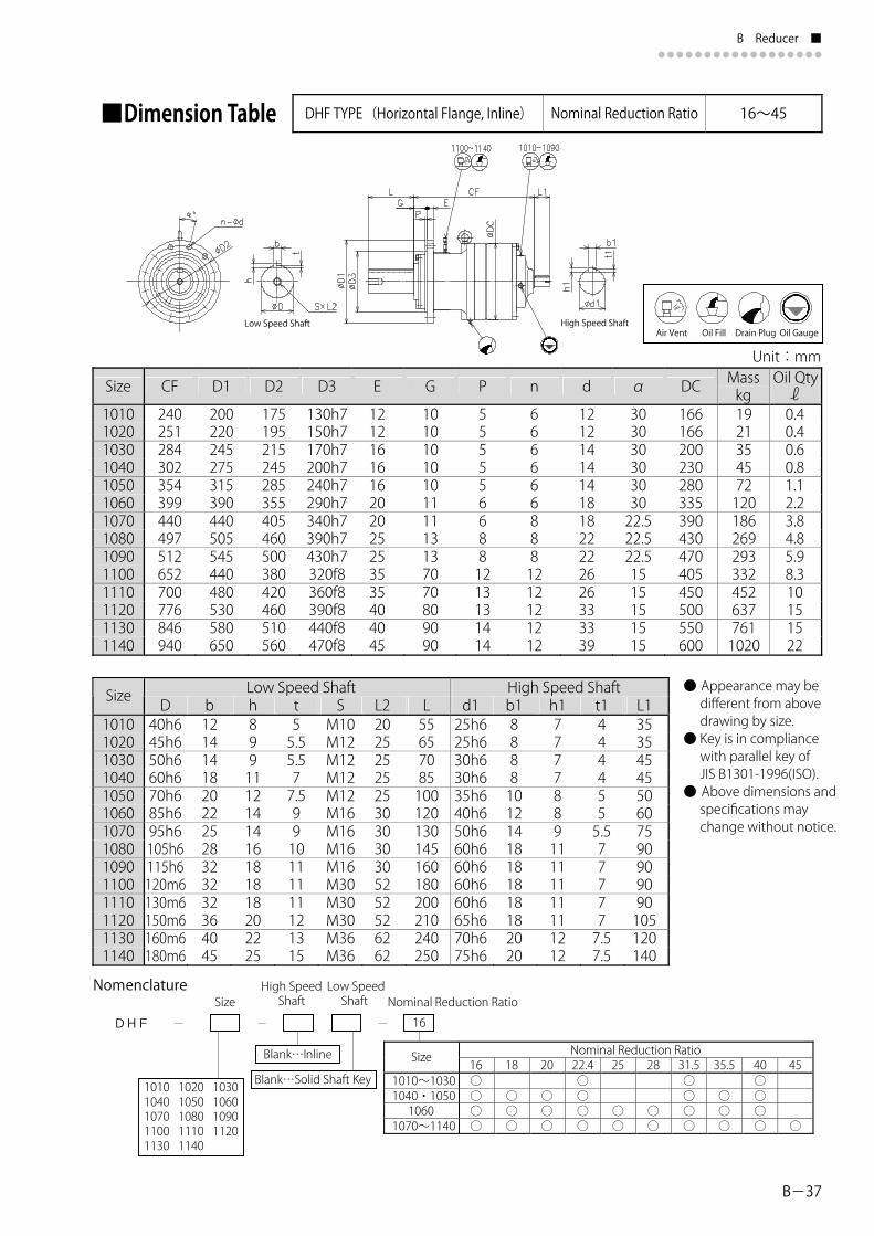
B-37
B Reducer ■●●●●●●●●●●●●●●●●●●
■Dimension Table DHF TYPE(Horizontal Flange, Inline) Nominal Reduction Ratio 16~45
Unit:mmMasskg
Low Speed Shaft High Speed Shaft Size● Appearance may be different from above drawing by size.
● Key is in compliance with parallel key of JIS B1301-1996(ISO).
● Above dimensions and specifications may change without notice.
Nomenclature
DHF 16
1010 1020 1030 1040 1050 1060 1070 1080 1090 1100 1110 1120 1130 1140
Nominal Reduction RatioSizeBlank…Inline
Blank…Solid Shaft Key
Size High Speed Shaft Nominal Reduction Ratio
Low Speed Shaft
Oil Qtyℓ Size CF D1 D2 D3 E G P n d α DC
1010 240 200 175 130h7 12 10 5 6 12 30 166 19 0.4 1020 251 220 195 150h7 12 10 5 6 12 30 166 21 0.4 1030 284 245 215 170h7 16 10 5 6 14 30 200 35 0.6 1040 302 275 245 200h7 16 10 5 6 14 30 230 45 0.8 1050 354 315 285 240h7 16 10 5 6 14 30 280 72 1.1 1060 399 390 355 290h7 20 11 6 6 18 30 335 120 2.2 1070 440 440 405 340h7 20 11 6 8 18 22.5 390 186 3.8 1080 497 505 460 390h7 25 13 8 8 22 22.5 430 269 4.8 1090 512 545 500 430h7 25 13 8 8 22 22.5 470 293 5.9 1100 652 440 380 320f8 35 70 12 12 26 15 405 332 8.3 1110 700 480 420 360f8 35 70 13 12 26 15 450 452 10 1120 776 530 460 390f8 40 80 13 12 33 15 500 637 15 1130 846 580 510 440f8 40 90 14 12 33 15 550 761 15 1140 940 650 560 470f8 45 90 14 12 39 15 600 1020 22
D b h t S L2 L d1 b1 h1 t1 L1 1010 40h6 12 8 5 M10 20 55 25h6 8 7 4 35 1020 45h6 14 9 5.5 M12 25 65 25h6 8 7 4 35 1030 50h6 14 9 5.5 M12 25 70 30h6 8 7 4 45 1040 60h6 18 11 7 M12 25 85 30h6 8 7 4 45 1050 70h6 20 12 7.5 M12 25 100 35h6 10 8 5 50 1060 85h6 22 14 9 M16 30 120 40h6 12 8 5 60 1070 95h6 25 14 9 M16 30 130 50h6 14 9 5.5 75 1080 105h6 28 16 10 M16 30 145 60h6 18 11 7 90 1090 115h6 32 18 11 M16 30 160 60h6 18 11 7 90 1100 120m6 32 18 11 M30 52 180 60h6 18 11 7 90 1110 130m6 32 18 11 M30 52 200 60h6 18 11 7 90 1120 150m6 36 20 12 M30 52 210 65h6 18 11 7 105 1130 160m6 40 22 13 M36 62 240 70h6 20 12 7.5 120 1140 180m6 45 25 15 M36 62 250 75h6 20 12 7.5 140
16 18 20 22.4 25 28 31.5 35.5 40 45 1010~1030 ○ ○ ○ ○ 1040・1050 ○ ○ ○ ○ ○ ○ ○ 1060 ○ ○ ○ ○ ○ ○ ○ ○ ○ 1070~1140 ○ ○ ○ ○ ○ ○ ○ ○ ○ ○
Low Speed Shaft High Speed ShaftAir Vent Oil Fill Drain Plug Oil Gauge
DP1000ENG.indd 47DP1000ENG.indd 47 15/05/15 19:0115/05/15 19:01

■ B Reducer●●●●●●●●●●●●●●●●●●
B-38
■Dimension Table DHF TYPE(Horizontal Flange, Inline) Nominal Reduction Ratio 50~224
Unit:mm
Size Nominal Reduction Ratio CF D1 D2 D3 E G P n d α DC Masskg
Oil Qty
50~90 441 127 2.51060 100~224 421 120 2.5 50~63 484 192 4.51070 71~224 467 180 4.5 50~63 552 286 5.71080 71~224 537 269 5.7 50~80 567 310 7.01090 90~224 552 297 7.0
Low Speed Shaft High Speed Shaft Size Nominal Reduction Ratio D b h t S L2 L d1 b1 h1 t1 L1
50~901060 100~22450~631070 71~22450~631080 71~22450~801090 90~224
● Appearance may be different from above drawing by size.
● Key is in compliance with parallel key of JIS B1301-1996 (ISO).
● Above dimensions and specifications may change without notice.
Nomenclature
DHF 50
1010 1020 1030 1040 1050 1060 1070 1080 1090 Nominal Reduction RatioSize
50 56 63 71 80 90 100 112 125 140 160 180 200 2241010~1040 ○ ○ ○ ○ ○ ○1050~1090 ○ ○ ○ ○ ○ ○ ○ ○ ○ ○ ○ ○ ○ ○
Blank…Inline
Blank…Solid Shaft Key
Size High Speed Low Speed Shaft Nominal Reduction Ratio Shaft
1010 - 272 200 175 130h7 12 10 5 6 12 30 166 22 0.41020 - 283 220 195 150h7 12 10 5 6 12 30 166 25 0.51030 - 309 245 215 170h7 16 10 5 6 14 30 200 36 0.61040 - 327 275 245 200h7 16 10 5 6 14 30 230 46 0.81050 - 383 315 285 240h7 16 10 5 6 14 30 280 74 1.3
390 355 290h7 20 11 6 6 18 30 335
440 405 340h7 20 11 6 8 18 22.5 390
505 460 390h7 25 13 8 8 22 22.5 430
545 500 430h7 25 13 8 8 22 22.5 470
1010 - 40h6 12 8 5 M10 20 55 25h6 8 7 4 351020 - 45h6 14 9 5.5 M12 25 65 25h6 8 7 4 351030 - 50h6 14 9 5.5 M12 25 70 25h6 8 7 4 351040 - 60h6 18 11 7 M12 25 85 25h6 8 7 4 351050 - 70h6 20 12 7.5 M12 25 100 30h6 8 7 4 45
35h6 10 8 5 50 85h6 22 14 9 M16 30 120 30h6 8 7 4 4540h6 12 8 5 60 95h6 25 14 9 M16 30 130 35h6 10 8 5 5050h6 14 9 5.5 75105h6 28 16 10 M16 30 145 40h6 12 8 5 6050h6 14 9 5.5 75115h6 32 18 11 M16 30 16040h6 12 8 5 60
ℓ
Low Speed Shaft High Speed Shaft
Air Vent Oil Fill Drain Plug Oil Gauge
DP1000ENG.indd 48DP1000ENG.indd 48 15/05/15 19:0115/05/15 19:01

B-39
B Reducer ■●●●●●●●●●●●●●●●●●●
■Dimension Table DHF TYPE(Horizontal Flange, Inline) Nominal Reduction Ratio 71~224
Unit:mm
Size CF D1 D2 D3 E G P n d α DC Mass kg
Oil Qty
Low Speed Shaft Size D b h t S L2 L d1 b1 h1 t1 L1 ● Appearance may be different from above drawing by size.
● Key is in compliance with parallel key of JIS B1301-1996(ISO).
● Above dimensions and specifications may change without notice.
Nomenclature
DHF 71
1100 1110 1120 1130 1140 1150 1160 1170 1180 1185 1190 1195 1200 1205 1210 1215 1220
Nominal Reduction RatioSizeBlank…Inline
Blank…Solid Shaft Key
Size High Speed Low Speed Shaft Nominal Reduction Ratio Shaft
1100 668 440 380 320f8 35 70 12 12 26 15 405 320 91110 717 540 480 420f8 35 75 15 12 26 15 410 422 9.51120 795 570 510 450f8 40 80 15 16 26 11.25 460 610 111130 846 625 555 485f8 40 90 15 16 33 11.25 510 690 161140 968 675 605 535f8 45 100 15 20 33 9 560 880 151150 1050 760 670 580f8 45 110 20 16 39 11.25 600 1190 181160 1189 810 720 630f8 50 120 20 20 39 9 650 1380 221170 1254 870 780 680f8 55 120 20 24 39 7.5 680 1780 251180 1315 930 840 730f8 55 120 20 24 39 7.5 730 2490 281185 1338 1000 910 800f8 55 120 20 30 39 6 805 2800 351190 1470 1050 950 830f8 60 125 20 24 45 7.5 835 3230 401195 1521 1100 1000 880f8 60 125 20 30 45 6 890 3550 461200 1604 1180 1070 940f8 65 130 20 24 52 7.5 940 4820 521205 1636 1220 1110 980f8 65 130 20 24 52 7.5 980 5610 581210 1810 1300 1190 1050f8 70 145 20 24 52 7.5 1030 6520 631215 1846 1340 1230 1090f8 70 145 20 30 52 6 1070 6820 701220 2010 1450 1340 1200f8 75 150 25 30 52 6 1130 8000 77
1100 120m6 32 18 11 M30 52 180 40h6 12 8 5 601110 130m6 32 18 11 M30 52 200 50h6 14 9 5.5 751120 150m6 36 20 12 M30 52 210 60h6 18 11 7 901130 160m6 40 22 13 M36 62 240 60h6 18 11 7 901140 180m6 45 25 15 M36 62 250 60h6 18 11 7 901150 200m6 45 25 15 M36 62 280 60h6 18 11 7 901160 220m6 50 28 17 M36 62 300 65h6 18 11 7 1051170 240m6 56 32 20 M36 62 360 70h6 20 12 7.5 120 1180 260m6 56 32 20 M36 62 390 70h6 20 12 7.5 1201185 260m6 56 32 20 M36 62 390 70h6 20 12 7.5 1201190 280m6 63 32 20 M36 62 450 75h6 20 12 7.5 1401195 280m6 63 32 20 M36 62 450 95h6 25 14 9 1501200 320m6 70 36 22 M42 73 510 95h6 25 14 9 1501205 320m6 70 36 22 M42 73 510 95h6 25 14 9 1501210 360m6 80 40 25 M42 73 570 120h6 32 18 11 1701215 360m6 80 40 25 M42 73 570 120h6 32 18 11 1701220 400m6 90 45 28 M48 80 630 130h6 32 18 11 190
ℓ
71 80 90 100 112 125 140 160 180 200 224 1110~1160 ○ ○ ○ ○ ○ ○ ○ ○ ○ ○ 1170 ○ ○ ○ ○ ○ ○ ○ ○ ○ 1180 ○ ○ ○ ○ ○ ○ ○ ○ ○ ○ 1185 ○ ○ ○ ○ ○ ○ ○ ○ 1190 ○ ○ ○ ○ ○ ○ ○ ○ ○ ○ 1195 ○ ○ ○ ○ ○ ○ ○ ○ 1200 ○ ○ ○ ○ ○ ○ ○ ○ 1205 ○ ○ ○ ○ ○ ○ ○ 1210 ○ ○ ○ ○ ○ ○ ○ ○ ○ 1215 ○ ○ ○ ○ ○ ○ ○ ○ ○ 1220 ○ ○ ○ ○ ○ ○ ○ ○ ○ ○
High Speed Shaft
Low Speed Shaft High Speed ShaftAir Vent Oil Fill Drain Plug Oil Gauge
DP1000ENG.indd 49DP1000ENG.indd 49 15/05/15 19:0115/05/15 19:01

■ B Reducer●●●●●●●●●●●●●●●●●●
B-40
■Dimension Table DHF TYPE(Horizontal Flange, Inline) Nominal Reduction Ratio 315~1400
Unit:mm
Size CF D1 D2 D3 E G P n d α DC Mass kg
Oil Qty
200220245275315390440505545
666666888
166166200230280335390430470
30303030303022.522.522.5
121214141418182222
555556688
101010101011111313
121216161620202525
130h7150h7170h7200h7240h7290h7340h7390h7430h7
175195215245285355405460500
304315341359401446482559574
1010 1020103010401050106010701080 1090
26 28 395074121179268292
0.4 0.5 0.7 0.9 1.4 2.7 4.9 6.8 8.0
Low Speed Shaft High Speed Shaft SizeD b h t S L2 L d1 b1 h1 t1 L1
● Appearance may be different from above drawing by size. ● Key is in compliance with parallel key of JIS B1301-1996(ISO). ● Above dimensions and specifications may change without notice.
Nomenclature
DHF 315
1010 1020 1030 1040 1050 1060 1070 1080 1090 Nominal Reduction RatioSize
Blank…Inline
Blank…Solid Shaft Key
Size High Speed Low Speed Shaft Nominal Reduction Ratio Shaft
ℓ
1010 40h6 12 8 5 M10 20 55 25h6 8 7 4 35 1020 45h6 14 9 5.5 M12 25 65 25h6 8 7 4 35 1030 50h6 14 9 5.5 M12 25 70 25h6 8 7 4 35 1040 60h6 18 11 7 M12 25 85 25h6 8 7 4 35 1050 70h6 20 12 7.5 M12 25 100 25h6 8 7 4 35 1060 85h6 22 14 9 M16 30 120 25h6 8 7 4 35 1070 95h6 25 14 9 M16 30 130 25h6 8 7 4 35 1080 105h6 28 16 10 M16 30 145 30h6 8 7 4 45 1090 115h6 32 18 11 M16 30 160 30h6 8 7 4 45
315 355 400 450 500 560 630 710 900 1000 1120 1250 1400 1010~1070 ○ ○ ○ ○ ○ ○ 1080・1090 ○ ○ ○ ○ ○ ○ ○ ○ ○ ○ ○ ○ ○
Low Speed Shaft High Speed Shaft
Air Vent Oil Fill Drain Plug Oil Gauge
DP1000ENG.indd 50DP1000ENG.indd 50 15/05/15 19:0115/05/15 19:01

B-41
B Reducer ■●●●●●●●●●●●●●●●●●●
■Dimension Table DHF TYPE(Horizontal Flange, Inline) Nominal Reduction Ratio 250~1120
Unit:mmNominal
Reduction RatioMasskg
Oil Qty
Low Speed Shaft High Speed ShaftSize Nominal Reduction Ratio
Nomenclature
DHF 315
1100 1110 1120 1130 1140 1150 1160 1170 1180 1185
Nominal Reduction RatioSize
Blank…Inline
Blank…Solid Shaft Key
Size High Speed Low Speed Shaft Nominal Reduction Ratio Shaft
● Appearance may be different from above drawing by size.
● Key is in compliance with parallel key of JIS B1301-1996(ISO).
● Above dimensions and specifications may change without notice.
ℓ Size CF D1 D2 D3 E G P n d α DC
250~450 710 500~1120 690 1100 440 380 320f8 35 70 12 12 26 15 405 330 10.5
1110 540 480 420f8 35 75 15 12 26 15 410 435 11 250~280 761 315~1120 744
1120 570 510 450f8 40 80 15 16 26 11.25 460 580 12.5 250・280 850 315~1120 835 250~400 901 450~1120 886 1130 625 555 485f8 40 90 15 16 33 11.25 510 690 15.5
1140 - 984 675 605 535f8 45 100 15 20 33 9 560 850 16 1150 - 1088 760 670 580f8 45 110 20 16 39 11.25 600 1100 17 1160 - 1230 810 720 630f8 50 120 20 20 39 9 650 1350 20.5 1170 - 1262 870 780 680f8 55 120 20 24 39 7.5 680 1700 24 1180 - 1321 930 840 730f8 55 120 20 24 39 7.5 730 2450 26 1185 - 1344 1000 910 800f8 55 120 20 30 39 6 805 2720 31
D b h t S L2 L d1 b1 h1 t1 L1 250~450 35h6 10 8 5 50 1100 120m6 32 18 11 M30 52 180 500~1120 30h6 8 7 4 45
1110 130m6 32 18 11 M30 52 200 315~1120 35h6 10 8 5 50 250~280 40h6 12 8 5 60
250・280 50h6 14 9 5.5 75 315~1120 40h6 12 8 5 60 1120 150m6 36 20 12 M30 52 210
250~400 50h6 14 9 5.5 75 450~1120 40h6 12 8 5 60 1130 160m6 40 22 13 M36 62 240
1140 - 180m6 45 25 15 M36 62 250 40h6 12 8 5 60 1150 - 200m6 45 25 15 M36 62 280 50h6 14 9 5.5 75 1160 - 220m6 50 28 17 M36 62 300 60h6 18 11 7 90 1170 - 240m6 56 32 20 M36 62 360 60h6 18 11 7 90 1180 - 260m6 56 32 20 M36 62 390 60h6 18 11 7 90 1185 - 260m6 56 32 20 M36 62 390 60h6 18 11 7 90
250 280 315 355 400 450 500 560 630 710 800 900 1000 1120 1100~1130 ○ ○ ○ ○ ○ ○ ○ ○ ○ ○ ○ ○ ○ ○ 1140 ○ ○ ○ ○ ○ ○ ○ ○ ○ 1150~1170 ○ ○ ○ ○ ○ ○ ○ ○ ○ ○ 1180 ○ ○ ○ ○ ○ ○ ○ ○ ○ ○ 1185 ○ ○ ○ ○ ○ ○ ○ ○
Low Speed Shaft High Speed Shaft Air Vent Oil Fill Drain Plug Oil Gauge
DP1000ENG.indd 51DP1000ENG.indd 51 15/05/15 19:0115/05/15 19:01

■ B Reducer●●●●●●●●●●●●●●●●●●
B-42
■Dimension Table DHF TYPE(Horizontal Flange, Inline) Nominal Reduction Ratio 355~1120
Unit:mmMasskg
Oil Qty
Low Speed Shaft High Speed ShaftSize
● Appearance may be different from above drawing by size. ● Key is in compliance with parallel key of JIS B1301-1996(ISO). ● Above dimensions and specifications may change without notice.
Nomenclature
DHF 355
1190 1195 1200 1205 1210 1215 1220
Nominal Reduction RatioSize
Blank…Inline
Blank…Solid Shaft Key
Size High Speed Low Speed Shaft Nominal Reduction Ratio Shaft
ℓ Size CF D1 D2 D3 E G P n d α DC
1190 1526 1050 950 830f8 60 125 20 24 45 7.5 835 3130 36 1195 1567 1100 1000 880f8 60 125 20 30 45 6 890 3450 43 1200 1685 1180 1070 940f8 65 130 20 24 52 7.5 940 4700 47 1205 1717 1220 1110 980f8 65 130 20 24 52 7.5 980 5500 53 1210 1885 1300 1190 1050f8 70 145 20 24 52 7.5 1030 6320 57 1215 1937 1340 1230 1090f8 70 145 20 30 52 6 1070 6700 66 1220 2099 1450 1340 1200f8 75 150 25 30 52 6 1130 7800 70
D b h t S L2 L d1 b1 h1 t1 L1 1190 280m6 63 32 20 M36 62 450 60h6 18 11 7 90 1195 280m6 63 32 20 M36 62 450 60h6 18 11 7 90 1200 320m6 70 36 22 M42 73 510 65h6 18 11 7 105 1205 320m6 70 36 22 M42 73 510 65h6 18 11 7 105 1210 360m6 80 40 25 M42 73 570 70h6 20 12 7.5 120 1215 360m6 80 40 25 M42 73 570 70h6 20 12 7.5 120 1220 400m6 90 45 28 M48 80 630 75h6 20 12 7.5 140
355 400 450 500 560 630 710 800 900 1000 1120 1190 ○ ○ ○ ○ ○ ○ ○ ○ ○ ○ 1195 ○ ○ ○ ○ ○ ○ ○ ○ ○ 1200 ○ ○ ○ ○ ○ ○ ○ ○ ○ ○ 1205 ○ ○ ○ ○ ○ ○ ○ ○ ○ 1210 ○ ○ ○ ○ ○ ○ ○ ○ ○ ○ 1215 ○ ○ ○ ○ ○ ○ ○ ○ ○ 1220 ○ ○ ○ ○ ○ ○ ○ ○ ○ ○
Low Speed Shaft High Speed Shaft
Air Vent Oil Fill Drain Plug Oil Gauge
DP1000ENG.indd 52DP1000ENG.indd 52 15/05/15 19:0115/05/15 19:01

C
Technical Data
Lubrication and Installation
Painting Specifications and Rust Proof Standard
Moment of Inertia
Specifications/Dimensions for Spline shaft
Dimensions of Motor Adapter JEM / IEC
Warranty Policy
Safety Precautions
Inquiry / Order Specification Sheet form
C-2
C-3
C-4
C-6
C-7
C-8
C-9
C-10
DP1000ENG.indd 53DP1000ENG.indd 53 15/05/14 10:5415/05/14 10:54

■ C Technical Data●●●●●●●●●●●●●●●●●●
C-2
■Lubrication1. Standard Lubrication Method
2. Recommended Lubricants
・Oil bath lubrication is applied to all models.・Grease lubrication for some right angle input shaft.
・The grease lubrication part is filled up with grease when shipping and you may use as it is.
Ambient Temperature
ISO AGMA
-10 deg to +25 deg
VG150 4EP
+10 deg to +40 deg
VG220 5EP G
ear Oil
+30 deg to +50 deg
VG320 6EP
Bearing grease
3. Time of replenishment and replacement. ・Lubricant has been evacuated on shipment. Be sure to replenish lubricant up to the standard level of oil gauge. It is recommended to replace lubricant after 500 hours operation for the first time and in every 2500 hours or every half year, whichever comes first, after then.
4. Consult us when the ambient temperature is lower than -10℃ or higher than +40℃, when the standard input speed will be over 1800r/min or when irregular operating condition will be required.
■Installation(1) Consult us when the product is to be installed on an inclined surface or on a ceiling. Additional lubrication system may be necessary.
(2) Install the product horizontally on a sufficiently rigid base. When the product is made for inclined installation according to your specification, do not install it at any other angle than the specified angle.
(3) Installation bolts for the reducer shall be equivalent to JIS(ISO) strength classification 10.9. Consult us when the force that pushes up reducer is to be applied.
(4) Refer to the maintenance manual attached to the product for other remarks regarding to installation and
BP CASTROL
ENERGOLGR-XP-150
ALPHASP150
OPTIGEARBM150
TRIBOL1100/150
GEARCOMPOUNDSEP150
MEROPAWM150
SPARTANEP150
MOBIL-GEAR629
OMALA150
CARTEREP150
ENERGOLGR-XP-220
ALPHASP220
OPTIGEARBM220
TRIBOL1100/220
GEARCOMPOUNDSEP220
MEROPAWM220
SPARTANEP220
MOBIL-GEAR630
OMALA220
CARTEREP220
ENERGOLGR-XP-320
ALPHASP320
OPTIGEARBM320
TRIBOL1100/320
GEARCOMPOUNDSEP320
MEROPAWM320
SPARTANEP320
MOBIL-GEAR632
OMALA320
CARTEREP320
ENER-GREASELS EP2
SPHEEROLAP3
Olista Long-time 3EP
TRIBOL 3020/1000-2
DURALITHGREASE 68
MULTI-FAK EP2
BEACONEP2
MOBIL-PLEX ALVANIA
EP2MULTISEP2
CHEVRON TEXACO EXXON MOBIL SHELL TOTAL
48
maintenance.
DP1000ENG.indd 54DP1000ENG.indd 54 15/06/02 16:1115/06/02 16:11

C-3
C Technical Data ■●●●●●●●●●●●●●●●●●●
■Painting SpecificationsKind of Painting Painting Specification
SurfaceCondition Class Finish Coat
Days Type (Thickness:μm) Type of Coating Application
- Under 1(20~40) Modified epoxy resin Standard under coat
Standard paintingPhallic acid
0Finish 1
(15~30) Alkyd resin paint Standard finish coat
- Under 2(40~80) Modified epoxy resinStandard export
panting Modified epoxy2Finish 1
(15~30) Vinyl modified epoxy resinExport standard
Under 1(20~40) Vinyl modified epoxy resin
Modified epoxy 3Finish 2
(30~60) Vinyl modified epoxy resin
Moderate corrosiveatmosphere, seaside,outdoor humidatmosphere, etc.
Under 2(40~70) Lead rust preventive paintLong of oil
phallic 7Finish 2
(30~60) Synthetics resin paint
Ocean-going vessels,bridge, seaside,outdoor humidatmosphere, etc.
Under 2(40~70) Lead rust preventive paint
Second 1(20~40) Phenol M.I.O. paintChloride rubber 10
Finish 2(40~70) Chloride rubber paint
Ocean-going vessels,bridge, seaside,outdoor humidatmosphere, etc.
Under 2(40~70) Lead rust preventive paint
Phenol 7Finish 2
(30~60) Phenol resin enamel
In-and-outdoor ofacid treating plantand chemical plant,
etc.
Under 1(20~40) Lead rust preventive paint
Special painting(Including rust-proof and heatresisting painting)One layer ofModified epoxyresin Primer as thefirst prime
Heat-proof silver 7Finish 1
(15~30) Aluminum paint
Heatingfurnace(120℃),
etc.
Under 1(50~60)
Special permeability epoxyaluminum paintEpoxy 10
Finish 3(120~240) Polyamide epoxy
Nuclear powergeneration
Under 1(50~60)
Special permeability epoxyaluminum paint
Extra rust-proofpainting
Polyurethane 10Finish 3
(45~90)Polyisocyanate urethane
resin paint
Nuclear powergeneration
Cast IronClass 1
SteelPlateClass 2
Extra rust-proofpainting(Sand blastunder coating)
Thick film epoxy 12 5(250~350)
Thick film type modified epoxyresin paint
Submersible equipment, marinestructure, etc.
Note: 1. Days mean extra days necessary for Special Painting in comparison with Standard Painting. 2. Our standard color is Donau Blue (equivalent Munsell color: 6.5PB 3.6 / 8.2).
■Rust Proof StandardRust proofing treatment has been conducted on all completely assembled models prior to shipment.
1. Standard rust proofing specifications (1) Outside rust proofing specifications
Rust proofing oil has been applied to products before shipment. Check the rust proofing conditions every 6 months after shipment, and conduct rust proofing treatment, if necessary.
(2) Inside rust proofing specificationsRust proofing period
Storage conditionGenerally to be stored inside the warehouse, relatively free of humidity, dust, extreme temperature fluctuation, corrosive gas, and similar atmosphere. After shipment, the product shall be operated 5-10 minutes every 2-3 months with our recommended lubricants.
2. Export rust proofing specifications Consult us for export rust proofing when export specifications or severe specifications are required.
Painting of
6 months
Coating
DP1000ENG.indd 55DP1000ENG.indd 55 15/05/14 10:5415/05/14 10:54

■ C Technical Data●●●●●●●●●●●●●●●●●●
C-4
■Moment of InertiaReducer Moment of Inertia [kg・㎡]
Size of ReducerNominalReduction Ratio 1010 1020 1030 1040 1050 1060 1070 1080 1090 1100 1110 1120 5 0.00028 0.00033 0.00075 0.00153 0.00390 0.01040 0.021109 0.00018 0.00018 0.00045 0.00098 0.00223 0.00643 0.01270 16 0.00042 0.00043 0.00107 0.00111 0.00308 0.00713 0.01951 0.03635 0.0378518 0.00111 0.00211 0.00536 0.01900 0.03141 0.0314120 0.00100 0.00198 0.00491 0.01900 0.02827 0.02827 0.01855 0.03188 0.05516 22.4 0.00025 0.00025 0.00066 0.00068 0.00185 0.00408 0.01143 0.02202 0.02290 0.01544 0.02653 0.0459125 0.00407 0.00950 0.02110 0.02261 0.01538 0.02642 0.0457128 0.00370 0.00841 0.01970 0.02019 0.01398 0.02402 0.04155 31.5 0.00019 0.00019 0.00047 0.00048 0.00128 0.00275 0.00799 0.01543 0.01585 0.01039 0.01785 0.03088 35.5 0.00046 0.00127 0.00263 0.00755 0.01444 0.01592 0.00995 0.01709 0.0295740 0.00016 0.00016 0.00041 0.00041 0.00106 0.00223 0.00663 0.01281 0.01285 0.00845 0.01452 0.0251245 0.00248 0.00663 0.01256 0.01256 0.00937 0.01611 0.0278750 0.00043 0.00043 0.00046 0.00046 0.00121 0.00328 0.00771 0.02061 0.02075 56 0.00121 0.00328 0.00771 0.01997 0.02001 63 0.00118 0.00320 0.00773 0.01255 0.01985 71 0.00042 0.00042 0.00044 0.00044 0.00113 0.00309 0.00348 0.00781 0.01964 0.00715 0.01957 0.0364680 0.00088 0.00153 0.00300 0.00707 0.00707 0.00538 0.01905 0.0315090 0.00025 0.00025 0.00026 0.00026 0.00069 0.00184 0.00208 0.00447 0.00452 0.00492 0.01905 0.02835100 0.00077 0.00127 0.00211 0.00423 0.00430 0.00409 0.01147 0.02209112 0.00072 0.00115 0.00197 0.00420 0.00419 0.00408 0.00950 0.02268125 0.00025 0.00025 0.00025 0.00025 0.00066 0.00070 0.00189 0.00410 0.00412 0.00371 0.00839 0.02025140 0.00063 0.00065 0.00165 0.00404 0.00404 0.00275 0.00801 0.01548160 0.00058 0.00060 0.00145 0.00353 0.00353 0.00304 0.00757 0.01597180 0.00018 0.00018 0.00019 0.00019 0.00048 0.00050 0.00126 0.00270 0.00271 0.00224 0.00665 0.01285200 0.00045 0.00047 0.00110 0.00240 0.00270 0.00665 0.01260224 0.00016 0.00016 0.00016 0.00016 0.00041 0.00042 0.00103 0.00220 0.00221 250 0.00328 0.00771 0.02061280 0.00328 0.00771 0.01997315 0.00043 0.00025 0.00043 0.00043 0.00043 0.00047 0.00059 0.00139 0.00140 0.00309 0.00773 0.01255355 0.00139 0.00140 0.00178 0.00348 0.00781400 0.00042 0.00042 0.00042 0.00042 0.00042 0.00044 0.00051 0.00128 0.00128 0.00153 0.00300 0.00707450 0.00126 0.00126 0.00184 0.00208 0.00447500 0.00113 0.00113 0.00115 0.00197 0.00505560 0.00025 0.00025 0.00025 0.00025 0.00025 0.00026 0.00031 0.00077 0.00077 0.00070 0.00189 0.00410630 0.00080 0.00080 0.00070 0.00172 0.00410710 0.00080 0.00080 0.00065 0.00165 0.00404800 0.00025 0.00025 0.00025 0.00025 0.00025 0.00025 0.00027 0.00070 0.00070 0.00060 0.00145 0.00353900 0.00063 0.00063 0.00050 0.00126 0.002701000 0.00057 0.00057 0.00047 0.00110 0.002831120 0.00018 0.00018 0.00018 0.00018 0.00018 0.00019 0.00020 0.00050 0.00050 0.00042 0.00103 0.002201250 0.00045 0.000451400 0.00016 0.00016 0.00016 0.00016 0.00016 0.00016 0.00017 0.00042 0.00042
Note: 1. Above figures are for high speed shaft.
DP1000ENG.indd 56DP1000ENG.indd 56 15/05/14 10:5415/05/14 10:54

C-5
C Technical Data ■●●●●●●●●●●●●●●●●●●
Size of Reducer1130 1140 1150 1160 1170 1180 1185 1190 1195 1200 1205 1210 1215 1220
0.08212 0.14927 0.06834 0.12422 0.06805 0.12370 0.06186 0.11244 0.04598 0.08357 0.04402 0.08002 0.03740 0.06798 0.04149 0.07542
0.03796 0.05113 0.08105 0.13407 0.03150 0.03845 0.06095 0.10081 0.14266 0.19030 0.36994 0.49312 1.97224 0.02835 0.03518 0.05577 0.09226 0.13055 0.17415 0.19152 0.33854 0.46111 0.64555 0.02297 0.02928 0.04642 0.07678 0.10865 0.14493 0.17681 0.28174 0.40388 0.53724 0.65930 0.91255 1.29388 1.50206 0.02268 0.02916 0.04622 0.07646 0.10819 0.14432 0.14615 0.28056 0.39983 0.53498 0.58391 0.90872 1.00514 1.49571 0.02025 0.02650 0.04201 0.06950 0.09834 0.13119 0.14595 0.25503 0.35535 0.48630 0.58105 0.82602 0.89313 1.35960 0.01590 0.01970 0.03123 0.05165 0.07309 0.09750 0.10122 0.18954 0.29087 0.36143 0.52933 0.61393 0.71544 1.01050 0.01597 0.02170 0.03441 0.05691 0.08053 0.10743 0.11218 0.20884 0.30054 0.39822 0.39987 0.67642 0.78985 1.11336 0.01285 0.01602 0.02540 0.04201 0.05945 0.07931 0.08210 0.15417 0.24993 0.29399 0.43104 0.49936 0.56374 0.82193 0.01260 0.01778 0.02818 0.04661 0.06596 0.08799 0.09113 0.17104
0.07188 0.13973 0.02075 0.02001 0.01985 0.01964 0.01957 0.03646 0.03646 0.13487 0.00707 0.00715 0.01905 0.03150 0.03150 0.03796 0.06397 0.06532 0.11653 0.13987 0.19065 0.19387 0.30292 0.00452 0.00538 0.01905 0.02835 0.02835 0.03150 0.03927 0.05308 0.05487 0.09669 0.11844 0.15819 0.16006 0.25135 0.00505 0.00492 0.01147 0.02209 0.02209 0.02835 0.03211 0.04777 0.04899 0.08702 0.10008 0.14237 0.14473 0.22621 0.00412 0.00409 0.00950 0.02268 0.02268 0.02297 0.02451 0.03870 0.04001 0.07050 0.08946 0.11535 0.11815 0.18328 0.00412 0.00408 0.00839 0.02025 0.02025 0.02266 0.02409 0.03822 0.03599 0.06962 0.07316 0.11390 0.11667 0.18097 0.00404 0.00371 0.00801 0.01548 0.01548 0.02025 0.02222 0.03412 0.02734 0.06216 0.06418 0.10169 0.10234 0.16158 0.00353 0.00275 0.00757 0.01597 0.01597 0.01590 0.01631 0.02679 0.02755 0.04880 0.04997 0.07984 0.08511 0.12685 0.00271 0.00304 0.00665 0.01285 0.01285 0.01597 0.01650 0.02691 0.04903 0.08021 0.08703 0.12744 0.00283 0.00224 0.00665 0.01260 0.01260 0.01285 0.01343 0.02165 0.02238 0.03945 0.05081 0.06453 0.06686 0.10254 0.00221 0.00249 0.01260 0.02123 0.02204 0.04077 0.06328 0.10054
0.45258 0.50733 0.744930.32616 0.34980 0.55401 0.59981 0.91187
1.09652 1.43211 1.80483
DP1000ENG.indd 57DP1000ENG.indd 57 15/05/14 10:5415/05/14 10:54

■ C Technical Data●●●●●●●●●●●●●●●●●●
C-6
■Specifications/Dimensions for Spline Shaft In case spline shaft is used for slow speed shaft, dimensions are as follows.
(Unit:mm)Size Spline spec. φD(max) φDE L LE W S L2 1100 120×22×5 119 - 100 100 63 M16 321110 130×24×5 129 - 110 110 80 M20 451120 150×18×7.5 148.5 - 120 120 80 M20 451130 160×19×7.5 158.5 - 130 130 100 M24 511140 180×22×7.5 178.5 - 150 150 100 M24 511150 200×25×7.5 198.5 200p6 220 160 125 M30 641160 220×20×10 218 220p6 250 170 125 M30 641170 240×22×10 238 240p6 260 180 125 M30 641180 260×24×10 258 260p6 260 180 160 M36 70
260×24×10 258 260p6 260 180 160 M36 701190 280×26×10 278 280p6 300 220 160 M36 70 1195 280×26×10 278 280p6 300 220 160 M36 70 1200 320×30×10 318 320r6 320 240 200 M36 70 1205 320×30×10 318 320r6 320 240 200 M36 70 1210 360×34×10 358 360r6 330 250 200 M36 70 1215 360×34×10 358 360r6 330 250 200 M36 70 1220 400×38×10 398 400r6 340 260 250 M36 70
Gear standard:In conformity with JIS B1603-1995 attachment “Involute Spline (standard pressure angle 20°)”. (Same as old standard JIS D2001-1959”Involute Spline for automobiles”.)
W
φD(max)
2-S×L2
LE
L
φDE
1185
DP1000ENG.indd 58DP1000ENG.indd 58 15/05/14 10:5415/05/14 10:54

C-7
C Technical Data ■●●●●●●●●●●●●●●●●●●
■Dimensions of Motor Adapter J EM / I E C
Unit : mm JEM (Standard) IEC Motor
Capcity code kW×pole Frame
size kW×pole Frame size A LB C D E φMS H I LA LN LZ
02 0.2×4P 63 - 160 110 23 13 4.5 11 - - 130 4 1005 0.4×4P 71 0.25×4P,0.37×4P1 0.75×4P 80 0.55×4P,0.75×4P2 1.5×4P 90L 1.1×4P,1.5×4P,1.85×4P3 2.2×4P 100L 2.2×4P,3×4P5 3.7×4P 112M 4×4P8 5.5×4P 132S 5.5×4P10 7.5×4P 132M 7.5×4P15 11×4P 160M 11×4P20 15×4P 160L 15×4P25 18.5×4P 180M -- - - 18.5×4P30 22×4P 180M -- - - 22×4P40 30×4P 180L 30×4P50,60 200L 37×4P, 45×4P75 55×4P 225S 55×4P
63718090L100L112M132S132M160M160L-
180M*-
180L*200L225S250M
Note 1. Motor adapters with other dimensions than as listed in this table can be also manufactured. Please send us your inquiry. Note 2. Special adapter may be necessary for these flanges with * mark. Please consult us when you need them.
37×4P,45×4P
160 110 30 13 4.5 14 16.3 5 130 4 10200 130 40 13 4.5 19 21.8 6 165 4 12200 130 50 13 4.5 24 27.3 8 165 4 12250 180 60 13 5 28 31.3 8 215 4 15250 180 60 13 5 28 31.3 8 215 4 15300 230 80 15 5 38 41.3 10 265 4 15300 230 80 15 5 38 41.3 10 265 4 15350 250 110 18 6 42 45.3 12 300 4 19350 250 110 18 6 42 45.3 12 300 4 19400 300 110 18 6 48 51.8 14 350 4 19350 250 110 18 6 42 45.3 12 300 4 19400 300 110 18 6 48 51.8 14 350 4 19350 250 110 18 6 42 45.3 12 300 4 19400 300 110 18 6 55 59.3 16 350 4 19450 350 140 22 6 60 64.4 18 400 8 19550 450 140 22 6 65 69.4 18 500 8 19
DP1000ENG.indd 59DP1000ENG.indd 59 15/05/14 10:5415/05/14 10:54

■ C Technical Data●●●●●●●●●●●●●●●●●●
C-8
Guarantee standard
WarrantyPeriod
WarrantyCondition
Exception for
Warranty
The warranty period for the Products shall be 18 months after the commencement of delivery or 18 months after the shipment of the Products from the seller's works or 12 months from the Products coming into operation, whether comes first.
In Case that any problems, troubles or damages on the Products arise due to the defects in the Products during the above "Warranty Period" , although the Products are appropriately and properly installed in, connected or combined to the equipment or machines, or maintained in accordance with the mainte-nance manual and are properly operated under the conditions as described in the catalogue or other-wise as agreed upon in writing between the Seller and the Buyer or its customers, the Seller will provide, at its sole discretion, appropriate repair or replacement on the Products free of charge, except as stipu-lated in the "Exception for Warranty" as described below.However, in the event that the Products is installed in, connected or combined to or integrated into the equipment or machines, the Seller shall not reimburse the costs for removal or re-installation of the Products or other incidental costs related thereto and any lost opportunity, loss of profit or any other incidental or consequential losses or damages incurred by the Buyer or its customers.
Notwithstanding the above warranty, the warranty as set forth herein shall not be applied to the problems, troubles or damages on the Products which are caused by:1. installations, connections, combinations or integration of the Products in or to the other equipment or machines, which are rendered by any person or entity other than the Seller,
2. the insufficient maintenance or improper operation by the Buyer or its customers, such that the Product is not appropriately maintained in accordance with the maintenance manual provided or designated by the Seller,
3. the improper use or operation of the Products by the Buyer or its customers which are not informed to the Seller, including, without limitation, the Buyer's or its customers' operation of the Products not in conformity with the specifications, or use of the lubrication oil in the Products which is not recommended by the Seller,
4. troubles, problems or damages on any equipment or machines in or to which the Products are installed, connected or combined or installed, or any specifications particular to the Buyer or its customers.
DP1000ENG.indd 60DP1000ENG.indd 60 15/05/14 10:5415/05/14 10:54

C-9
C Technical Data ■●●●●●●●●●●●●●●●●●●
SAFETY PRECAUTIONS
General
1. Strictly observe the safety rules for the installation place and the equipment to use. (Industrial Safety and Health Law, Technical Standard for Electric Facilities, Extension Rules, Plant Explosion Guidelines, Building Standards Law, etc.)
2. Carefully read the maintenance manual before use. The maintenance manual should be sent to the actual user.
3. Strictly confirm the power source has been off before installation or removal of the product. 4. Install a protective cover on the coupling joint.
Selection
1. Select an appropriate product that matches the operating environment and usage.2. Consult us when the machine is used for transportation of passengers. Install a protective equipment on the machine side for safety sake.
3. Use the explosion-proof type motor when the using condition may be explosive. 4. When the machine is used for food processing and others that are susceptible to oil, install an oil pan or other damage preventive devices in case of oil leakage.
DP1000ENG.indd 61DP1000ENG.indd 61 15/05/14 10:5415/05/14 10:54

■ C Technical Data●●●●●●●●●●●●●●●●●●
C-10
11. Connection between motor and driven machine1. Application2. Quantity High speed shaft 3. Delivery date □Coupling 4. Delivery place □Chain/V belt 5. Nomenclature □Other( ) □Foot Mount □Flange Mount External Radial Load □Horizontal □Vertical F= N L= mm □Inline □Motor Direct Mount □Right Angle Low speed shaft
□Coupling 6. Prime mover □Gear □Electoric motor □Engine □Hydraulic motor □Other( )
External Radial Load 7. Reduction Ratio i= F= N L= mm
8. Using Conditions Input Speed _____________ r/min Normal torque of Low speed shaft ________ N・m Max. torque of Low speed shaft __________ N・m Transmission power ___________ kW Operating hours ____________ hours/day Operating duty ______________%/hour Direction of Rotation □One way □Bidirectional
12. Ambient conditions 9. Service Factor Location □Indoor-closed □Indoor-open □Outdoor
Ambient temperature MIN ℃ MAX ℃10. Bearing Life Dust □Much □Less Wind m/sec
Remarks
F
L
Data sheet for order and inquiry
DP1000ENG.indd 62DP1000ENG.indd 62 15/05/14 10:5415/05/14 10:54

DP1000ENG.indd 63DP1000ENG.indd 63 15/05/14 10:5415/05/14 10:54