world-wide technical reference guide · steinway & sons history steinway & sons was founded...
TRANSCRIPT

World-WideTechnical Reference Guide
2
TABLE OF CONTENTS
FOREWORD...................................................................................................................... 3
STEINWAY & SONS HISTORY....................................................................................... 4
A NOTE ON ENVIRONMENTAL CONDITIONS .......................................................... 6
GRAND PREPARATION.................................................................................................. 7
PRELIMINARY STEPS...................................................................................................... 8
GRAND ACTION DIAGRAM .......................................................................................... 9
BEDDING THE KEYFRAME TO KEYBED................................................................... 10
SETTING THE BALANCE RAIL STUDS ....................................................................... 12
EASE KEYS ...................................................................................................................... 14
KEY LEVEL...................................................................................................................... 16
SHARP HEIGHT.............................................................................................................. 17
SERVICING CLOTH-BUSHED ACTION CENTERS .................................................... 18
FACTORY STANDARD OF FRICTION FOR CLOTH BUSHINGS ............................. 19
ACTION PARTS ALIGNMENT...................................................................................... 20
TRAVELING HAMMERS ............................................................................................... 20
BURNING HAMMERS.................................................................................................... 21
SPACING HAMMERS TO STRINGS ............................................................................. 22
ALTERNATE REGULATION OF HAMMER SPACING .............................................. 24
SPACING REPETITIONS (WHIPPENS) ....................................................................... 27
SPACING FLIES............................................................................................................... 28
HAMBURG PREPARATION CHECKLIST ................................................................... 29

3
Foreword
This Technical Reference Guide has been prepared to be of benefit to piano technicians engaged in servicing Steinway & Sons (New York and Hamburg), Boston, and Essex pianos. It outlines procedures for service as used by our own technicians, and also provides the technician some general information and guidelines for finish care; plus tips, techniques, specifications, and historical information for the family of Steinway-produced pianos.
Following these instructions and guidelines will help to maintain the high standards of performance and appearance. Understanding the relationship between the action and keyboard will help in providing individualized service to the piano player.
If problems or questions arise concerning new or older Steinways that are not covered in this manual, please don’t hesitate to contact the Customer Satisfaction Department at the Steinway factory.
Steinway & SonsCustomer Satisfaction Department

4
Steinway & Sons History
Steinway & Sons was founded in 1853 by German immigrant Heinrich Engelhard Steinway in a Manhattan loft on Varick Street. “Henry” was a master cabinetmaker who built his first piano in the kitchen of his Seesen, Germany, home. By the time Henry established Steinway & Sons, he had built 482 pianos. The first piano produced by the company, number 483, was sold to a New York family for $500.
Over the next forty years, Henry and his sons C. F. Theodore, Charles, Henry Jr., William, and Albert developed the modern piano. Almost half of the company’s 124 patented inventions were developed during this period. Many of these late nineteenth-century inventions were based on emerging scientific research, including the acoustical theories of the renowned physicist Hermann von Helmholtz.
Steinway & Sons’ revolutionary designs and superior workmanship began receiving national recognition almost immediately. Starting in 1855, Steinway pianos received gold medals at several U.S. and European exhibitions. The company gained international recognition in 1867 at the Paris Exhibition when it was awarded the prestigious Grand Gold Medal of Honor for excellence in manufacturing and engineering. It was the first time an American company had received this award. Steinway pianos quickly became the piano of choice for many members of royal families and won the respect and admiration of the world’s great pianists.
In 1866, Steinway & Sons opened the first Steinway Hall on 14th Street. With a main auditorium of 2,000 seats, it became New York City’s artistic and cultural center, housing the New York Philharmonic until Carnegie Hall opened in 1891. By this time, the company had moved to its current location in the Astoria section of Queens, New York, and built Steinway Village. Virtually its own town, Steinway Village had its own foundries, factory, post office, parks and housing for employees.
In 1871, Henry Sr. died and sons C. F. Theodore and William assumed management of the operations. C. F. Theodore, an accomplished pianist, was responsible for the technical aspects of piano making and personally earned the company 46 patents, including one in 1875 for the modern concert grand piano. In the same year, William established a showroom in London. Five years later, in 1880, the Hamburg branch factory was established.
During the Depression (1931–36), the Steinway factory was run by a skeleton crew of foremen, office workers, and hundreds of part-time piano makers. The factory remained officially closed for 2 years during that period. Workers were brought back on an as-needed basis.
In 1941, World War II brought havoc to Steinway & Sons in Germany and America. Rationing of copper, iron, brass and felt forced Steinway out of the piano business. Women now entered the workforce. The Hamburg plant was producing wooden airplane decoys, bunk beds and

5
rifle stock to the Nazi war machine. Between the years of 1941–42 the New York plant was building gliders for the Army Air Force.
The New York plant was not allowed to construct pianos. The limitation order of April 1942 specifically stated that Steinway was forbidden to build pianos, which required such raw materials as iron, copper, and brass, considered strategic and needed for the military effort.
In 1950, Henry Z. Steinway issues a report on “Factory Consolidation,” an effort to streamline the manufacturing process. The process was that the parts were cut and shaped at Rikers, then were sent up the road a mile to Ditmars where they were assembled, regulated and shipped.
1951—Henry Z. Steinway won approval for his consolidation plan and received the funding to build an enormous covered woodshed next to the lumberyard.
1955—The board approved Fifth President Henry Z. Steinway’s plan for consolidation. This would enable them to accommodate the lacquer, belly, string, case parts and upright departments, general offices and a crosscut and pre-mill storage area. Henry adds 200,000 sq. ft. of factory and office space and proposes to close down the Ditmars factory at a cost of 1.3 million dollars. Making 12 pianos per day.
Today, Steinway & Sons crafts approximately 4,000 pianos a year world-wide. More than 1,300 prominent concert artists and ensembles across the world bear the title Steinway Artist. No artist or ensemble is a paid endorser of the piano. Each Steinway Artist owns a Steinway and has chosen to perform on the Steinway piano. In North America, artists may select a Steinway for concert performances from the company’s unique “piano bank,” an inventory of more than 300 pianos valued at over $15 million.
Heinrich Engelhard Steinway1797–1871
6
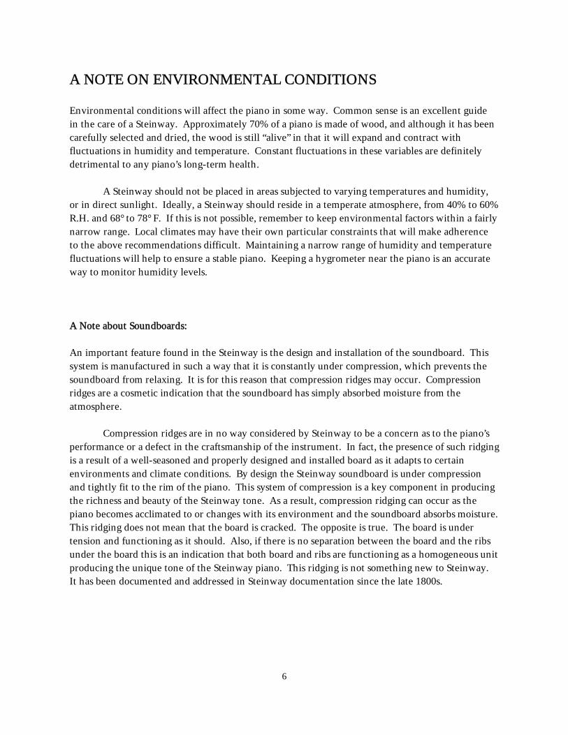
A NOTE ON ENVIRONMENTAL CONDITIONS
Environmental conditions will affect the piano in some way. Common sense is an excellent guide in the care of a Steinway. Approximately 70% of a piano is made of wood, and although it has been carefully selected and dried, the wood is still “alive” in that it will expand and contract with fluctuations in humidity and temperature. Constant fluctuations in these variables are definitely detrimental to any piano’s long-term health.
A Steinway should not be placed in areas subjected to varying temperatures and humidity, or in direct sunlight. Ideally, a Steinway should reside in a temperate atmosphere, from 40% to 60% R.H. and 68° to 78° F. If this is not possible, remember to keep environmental factors within a fairly narrow range. Local climates may have their own particular constraints that will make adherence to the above recommendations difficult. Maintaining a narrow range of humidity and temperature fluctuations will help to ensure a stable piano. Keeping a hygrometer near the piano is an accurate way to monitor humidity levels.
A Note about Soundboards:
An important feature found in the Steinway is the design and installation of the soundboard. This system is manufactured in such a way that it is constantly under compression, which prevents the soundboard from relaxing. It is for this reason that compression ridges may occur. Compression ridges are a cosmetic indication that the soundboard has simply absorbed moisture from the atmosphere.
Compression ridges are in no way considered by Steinway to be a concern as to the piano’s performance or a defect in the craftsmanship of the instrument. In fact, the presence of such ridging is a result of a well-seasoned and properly designed and installed board as it adapts to certain environments and climate conditions. By design the Steinway soundboard is under compression and tightly fit to the rim of the piano. This system of compression is a key component in producing the richness and beauty of the Steinway tone. As a result, compression ridging can occur as the piano becomes acclimated to or changes with its environment and the soundboard absorbs moisture. This ridging does not mean that the board is cracked. The opposite is true. The board is under tension and functioning as it should. Also, if there is no separation between the board and the ribs under the board this is an indication that both board and ribs are functioning as a homogeneous unit producing the unique tone of the Steinway piano. This ridging is not something new to Steinway. It has been documented and addressed in Steinway documentation since the late 1800s.

7
World-WideTechnical Reference Guide
Grand Preparation

8
GRAND ACTION PREPARATION AND REGULATION
The following pages outline suggested steps in regulating the grand piano. It should be noted that the specifications given are important; however, they may vary within reason, to accommodate individual needs of the piano player. It is important for the technician to understand the interrela-tionship between regulation procedures and how they affect the instrument’s performance, and to use this understanding in determining individual needs of the instrument and the performer. Since individual regulation steps affect others, repeating operations will be necessary in achieving stability.
PRELIMINARY STEPS
Before beginning to work on the piano it is important to make general assessments and observations of the instrument such as making sure that:
All screws are securely fastened, including those on:hingestrapwork pivot blockslyre and pedal assembliesplate flange cover striplockbars and topslipstoplidaction screws
Case parts are properly fit and functional, such as:keylid (fallboard)keyslipkeyblocks (cheekblocks)music desk and deskframelyre stickspedal assembly
Hinges are firm on their hinge pins, to avoid buzzes:continuous hingekeylid lip on Bs and Dskeylid pivot pintopstick hingebutt hinges
Trapwork is secure:Take out all lost motion between the pedal rods and trapwork levers.There should be no side play in the pedal assembly.

9
Preliminary regulation checks:
Check to ensure that the hammers are in acceptable condition and not excessively reduced in size as a result of wear and filing.
Make sure the hammershanks are off the hammer rest cushions to ensure weight on the capstans.
Ensure that repetition springs have tension enough to lift the hammers. Make sure that the hammer drop is not set higher than the let-off.
Diagram of Grand Action and Key (without Sostenuto)

10
BEDDING THE KEYFRAME TO KEYBED
Background: Steinway & Sons utilizes a keybed which is shaped and planed in such a way that it provides the keyframe with a solid support structure and minimal friction.
Keybed Design (New York Steinway)
The front lip of the keybed which contacts the keyframe (approximately 1/2") is crowned so that its center is approximately 1/32" higher than the ends.
The keybed bass and treble caps are planed straight, front to back.
The back rail of the keybed is planed straight, from bass to treble.
The front rail of the keyframe is reverse crowned so that the center of the front rail is approximately 1/32" lower than the ends. This is done to ensure stability at the front rail. There should be no gaps along this line of contact.
Note: Hamburg Steinway, Boston, and Essex pianos are designed with flat keybeds and do not utilize the criteria described above.
Hint: Utilize the shift pedal to check for free but firm movement of the keyframe. The keyframe should return to its original position smoothly when the shift pedal is released.
HOW: Careful planing and sanding of the keybed or keyframe can remove any hollows or spaces which otherwise would create a knocking noise during play. This has been performed at the factory and should require no adjustment in the field.
The middle portion of the keybed is slightly hollowed from the front rail to the back rail and from the bass cap to the treble cap, by approximately 1/32". This assures that only the balance rail studs will contact the keybed maple dowel inserts at the balance rail.

11
The back rail of the keyframe is held firmly in place, with minimal friction, with the aid of the dag blocks. These are glued onto the back rail of the keybed. The dag block and keyframe mating surface is graphited to ensure smooth and accurate shifting of the keyframe. Check to make sure that the dag blocks are in contact with the back rail.
HOW: If there is a space at this contact point, glue a veneer on the back rail of the keyframe and re-apply graphite. If there is too much friction at these points, lightly sand the keyframe as needed, and re-apply graphite.
The keyblocks should be fitted in such a way that they secure the keyframe in place, without inhibiting the free movement of the keyboard.
New York Steinway Grands:To remove looseness between the keyframe guide pins and the guide pin plate, a hammer (as shown in the photo) can be used to compress the fit to the pin. In cases of extreme wear, new plates should be ordered from the Steinway & Sons Parts Department.
See the chapter “Specifications and Service Techniques” for servicing the Hamburg keyblocks and guide pin plates.
bedding the keyframe
front rail
balance rail studs
back rail

12
SETTING BALANCE RAIL STUDS
Background: The Steinway keyframe is designed in such a way that there is contact between the keyframe and the keybed at the front rail, back rail, and the balance rail studs. The balance rail studs are regulated to remove any gap between the “floating” balance rail of the keyframe and the keybed, while providing minimal friction during the shifting of the keyframe.
The balance rail studs are positioned correctly when they just make contact to the hardwood dowel inserts of the keybed. These screws should never be used to regulate the amount of touch depth in the keyboard, as this would alter the regulation.
HOW: To correctly adjust the balance rail studs, first make sure that the keyboard is held firmly in place with the keyblocks.
Next, loosen all studs so that none of them contact the keybed. Pound the keyboard with a knocker stick or fingers at a point near the stud second from the treble end. At the same time, turn this stud down until a knocking sound begins then stops. The stud is now just in contact with the keybed. To check, lift up the stud with one hand, while tapping the keyframe with the other. A knocking sound should occur when upward pressure is applied, and then disappear when the stud is released. Depress the shift pedal fully three or four times and re-regulate if necessary. Regulate the next stud toward the bass in the same way; when completed, check the position of the first stud regulated and re-regulate if necessary. Regulate the other studs toward the bass in the same way. To regulate the stud at the bass end, pound on the keyboard near the stud second from the bass end. At the same time, turn the bass stud down until the stud second from the bass starts to knock. Then turn the bass stud back up until the knocking just stops. Depress the shift pedal fully three or four times and re-regulate if necessary. Regulate the stud at the treble end in the same way.
Lift stud until you introduce a knock this way.
Knock with other hand here.

13
The balance rail stud is correctly regulated when upward pressure is applied on the stud, the keyboard is tapped, and a knocking sound is detected. This knocking sound should disappear when the stud is released, denoting full but minimum contact between the keyboard and the keybed.
As the studs are adjusted, a ruler can be placed in front of the keys as a point of reference to assist in observing any unwanted movement of the keys. If the keys move upward in relation to the ruler, the studs have been adjusted too far downward. The balance rail studs must supply support to the keyboard but must not provide any lift to the keys. The balance rail studs should not be used to introduce more key dip or aftertouch.
A ruler can be placed in front of the keys to assist in observing any
unwanted movement of the keys.
The ruler provides a stationary point of reference to observe unwanted key movement as the glides are adjusted downward. Keys will exhibit faint upward
movement if the glides protrude too far below the balance rail.
Observe here.

14
EASE KEYS
Background: All keys must be free at the bearing points: front rail bushing, balance rail bushing and balance rail hole.
HOW:Step 1. Ease balance rail hole—The balance rail hole should be eased so that each key falls into
place with very slight downward pressure. There should be no backward to forward play in any key. Use a reaming tool to adjust the size of the balance hole. Hole size must be adjusted side-to-side only to prevent pully or chucking keys.
If moderate play exists, glue-sizing the hole with a mixture of hot water and glue (3:1 by volume) usually works well. If the play is excessive, shimming both sides of the hole approximately 1/16" from the edge of the hole will secure the key to the balance rail pin. Ream, if necessary, by using a tapered reaming tool inserted from the bushing side of thekey (shown in photo tothe right).
Step 2. Ease balance rail bushing—The balance rail bushing should have a small amount of play on both sides of the balance rail pin when the key is gently rotated side to side at its front. The amount of play should be consistent throughout the keyboard. Adjust (for play) by using key-easing pliers.

15
Step 3. Ease front rail bushing—The front rail bushing should have a slight amount of play from side to side (no more than 1/32") when the key is at the rest position and when it is depressed. Again, this should be consistent throughout the keyboard and should adjusted using key-easing pliers.

16
KEY LEVEL
Background: Steinway pianos have a “crowned” key level. The center of the keyboard is approxi-mately 1/32" higher than the ends. While using a crowned key level stick as a guide, adjust individual key heights by adding or removing paper punchings under the balance rail bearings (New York) or balance rail punchings (Hamburg, Boston, and Essex). The balance rail bearing should be positioned with its black line (scribed on the felt) towards the front rail.
HOW:
Step 1. Square and space keys—Make the keys parallel in the front by gently tapping the balance rail pin to the left or right. Avoid damaging the balance rail pin by using a small hammer and a hard-wood dowel such as a hammershank. It is important to space both the sharps and naturals.
Then, space the front of the keys by slightly bending the front rail pin, by using a spacing tool. Place the tool below the front rail punching to avoid damaging the surface of the pin.
Step 2. Set naturals—With the action and keyboard secured in the piano, the natural key height at both ends should be approximately 2-19/32" from the cut-out in the keybed to the underside of the key cover lip.* The factory uses a gauge as shown in picture to the right. Using a crowned key level stick as a guide, adjust accordingly by adding or removing paper punchings under the balance rail bearings.
* See the Regulation Specification Sheets in the “Specifications and Service Techniques” chapter for individual model specifications.
wo
Two punchings here …equals one
punching here.
squaring crooked key
Space keys with tool placed under the front rail washer.
measured from the ledge under the keyslip to
the underside of the end keys

17
Step 3. Set sharps—The sharps are also leveled with a 1/32" crown and set 1/2" above the naturals. The bass and treble guides are set properly when the sharp keystick is a postcard thickness higher than its adjacent natural key, at a point just behind the key covering when at rest.
Step 4. Set key stop rail—There should be approximately 1/16" between the tops of the keys and the key stop rail.
Hints: When doing key level, make sure that the back rail cloth of the keyframe is free from wood chips and debris.
Make sure the hammershanks are off the hammer rest cushions to ensure weight on the capstans.
Use the smallest amount of paper punching combinations to avoid sponginess in keyboard.
Also: Crowned key level sticks are available from the Steinway Parts Dept.
Sharp key height is ½" above naturals.
Sharp keystick will be slightly higher behind key coverings.

18
SERVICING CLOTH-BUSHED ACTION CENTERS
Background: Generally the manufacture and pinning of all action centers on Steinway pianos is done to achieve less than 4 grams rotating friction, and minimal side play. However, over the life of the instrument, whether due to wear, humidity conditions or other factors, it may become necessary to service the action centers for optimum performance.
IF ACTION CENTER IS TOO TIGHT:
If the center is too tight and is not the result of humidity—Check first for bent center pins, the presence of side play on wood parts, etc. If center pins are straight, proceed as follows:
Remove the selected part from the action or underlever assembly. Test for side play or side clearance. There should be minimal side play in the center.
Push out the center pin, being careful not to damage the bushing. If side clearance is to be increased, an often-used practice is to gently file the inside face of each bushed segment with a fine flat file. Care must be taken not to remove excessive material as it could create other problems.
UNDER NO CIRCUMSTANCES SHOULD THE BIRD’S-EYE, OR BUTTON, BE FILED OR TAMPERED WITH AS A CORRECTIVE MEASURE.
Check the diameter of the pin with a center pin gauge or micrometer. Select the next larger size center pin and test both sides of the bushing by inserting the center pin by hand through each bushed segment.
If the pin does not enter easily or turn freely, ream carefully with a straight-sided reamer. Ream the bushing until the pin enters and turns freely, but with some minimal resistance.
NOTE: On a new instrument only—The existing center pin may be used both to test and re-pin the component, providing, of course, that the pin remains tight in the wood. Under no circumstances use a smaller size pin, since the pin will not remain firmly inside the wood.
Push the center pin through both parts and re-pin the assembly. Drive the center pin flush to the outside edge of the flange. If the longer, pointed pin is used, follow the same procedure, but clip off the excess at both ends flush with the flange.
SERVICE TIP: A drop of undiluted methanol may also be applied to tight centers to resize the bushing cloth. Allow adequate drying time since bushings will tighten initially rendering the center unplayable. Upon drying, there should be a decrease in the action-center friction.

19
NOTE: Do not use a file for leveling pins. This creates burrs that get caught in the cloth, causing damage.
Retest action part for function and side play.
IF ACTION CENTERS ARE TOO LOOSE
NOTE: Check first to determine if travel is firm and straight. If it is, you are experiencing normal movement from Steinway & Sons’ cloth bushings and no adjustment is recommended. It should be noted that some centers can have a near zero gram reading and function perfectly well.
However, if wobbling is present during travel (excessive side play) check first for damaged bushings, cracked parts, etc., and replace as necessary. If all parts are found to be free from defects, re-pin as outlined in this bulletin, using at least the next larger size center pin.
FACTORY STANDARD OF FRICTION FOR CLOTH BUSHINGS
Within 1–4 grams rotating friction with minimal side play on all action centers. The use of a gram gauge applied to the flange is a preferred method for taking friction measurements. Steinway makes no recommendation as to the number of times a hammer is supposed to swing.
examples of gram resistance gauges available from piano supply sources

20
ACTION ALIGNMENT
NOTE: The following regulating steps include:
Traveling Hammers Burning Hammers Spacing Hammers Spacing Repetitions Spacing Flies
These steps are extremely important in developing optimal tonal and mechanical performance. All parts which do not travel straight, or are misaligned, will have a negative effect on the overall performance of the instrument.
A) TRAVELING HAMMERS
Background: All hammers should travel in a straight and vertical path.
HOW: Any hammers which move to the left should be corrected by inserting traveling paper underneath the left side of the hammershank flange on the action rail. Reverse this procedure for a hammer traveling to the right.
Hint: When checking for hammer travel, use a straightedge to lift several hammers simultaneously from their rest position to a height resembling the strings. Move these hammers up and down, while observing how the hammers travel individually and in relation to each other.
Traveling paper must be placed symmetrically here to avoid spacing shank unintentionally.
Place the paper on the opposite side of the flange from the direction it should move.

21
B) BURNING HAMMERS
Background: Hammershank “burning” is necessary when the vertical line of the hammer is not perpendicular to the horizontal line of the action rail.
HOW: To realign the hammers one must heat the hammershank along its entire length with an alcohol lamp or other heat source. While the hammershank is “hot,” hold the hammer and apply a twisting force towards the corrective direction. Since the hammer will have the tendency to return to its original position, this operation may need to be repeated several times.
Hints: In order to determine if a hammer needs burning, it is helpful to observe its position during its travel; the hammer tail should be positioned directly under the top of the hammer head and not to either side.
To prevent loose pinning—It is important to be careful during this procedure and avoid excessive force on the center pin bushing. Do not begin to “twist” the hammershank until it is heated. When using a flame, keep the heat source close to the hammershank so that the flame remains blue. Doing this will prevent the hammershank from turning black from carbonization.
The circled hammer below is not perpen-dicular to the adjacent hammers and
should be aligned by “burning” the shank.
“burning” the shank with a traditional alcohol lamp

22
C) SPACING HAMMERS TO STRINGS
Background: Accurate and consistent spacing of hammers to the strings is critical in achieving optimal and consistent voicing.
HOW: To move a hammer to its correct position, loosen the hammershank flange screw. Reposition the hammershank flange so that the hammer is correctly located. Then retighten the hammershank flange screw.
Step 1. Space hammers to trichord notes—The hammers are spaced correctly to the trichords when they are positioned off center, favoring the treble side. There should be approxi-mately twice as much of the exposed portion of the hammer on the treble side than on the bass side. The amount of hammer felt on the left side of the trichord must be spaced the same on every hammer in order to maintain an accurate left pedal voicing.
Hints: It is acceptable to space the trichord strings in the V-bar section to the hammers. This can be achieved only if the hammers are evenly spaced, correctly traveled and properly spaced within the scale. Take caution not to move the strings too close to the damper wire, which will cause buzzes. Keep the hammershank flanges evenly spaced with each other and 90 degrees to the action rail.
correct spacing of hammer on trichord notes

23
Step 2. Space hammers to bichords—The hammer is spaced correctly in relationship to the bichord when it is positioned off center, slightly favoring the bass side.
Step 3. Space hammers to unichords—The hammer is spaced correctly in relationship to the unichords when it is centered under the string.
Hint: If the hammershanks are centered on their corresponding repetitions, and the majority of hammers need to be spaced uniformly towards the bass or treble in their relation to the strings, shimming or removing material from the keyframe rest block will aid to relocate the keyframe and action under the strings.
The keyframe rest block is screwed into the bass side of the inner rim, and rests on the keybed. The keyframe rest block can be ad-justed to relocate the keyframe when at rest.

24
Alternate Regulation of Hammer Spacing
The traditional factory specification for spacing hammers to strings in New York Steinway grands has placed the hammer so that when it is blocked against the strings with the action in the rest position, about a string’s width of felt is visible on the bass or left side of the hammer. This allowed for the hammer to shift in the una corda or shift position so as to miss the third string and alter the volume and timbre of the sound.
An alternate spacing used in many concert instruments places the hammer slightly more to the left, approaching being centered under the strings.
In the shift position the third string is still struck. The change of timbre and volume is produced by the way in which the hammer is voiced in that part of the hammer that strikes the strings. Regulation of the shift pedal is set to move the hammer so that a different part of the hammer hits the strings compared to the no-shift, or rest, position.

25
A transfer mark of string/hammer contact made in the rest position will move just past centering between the strings of a trichord.
The hammers of the bass trichords can be regulated in the same way.

26
There is no change in the bass hammer spacing from the traditional methods.
Regulating the shift and the spacing in this way allows for very shallow needling in the felt between the strings without affecting either timbre or volume in the rest position. This can be done because of shallow needling and because the hammers allow very careful needling which does not affect the felt very far beyond the needle.

27
D) SPACING REPETITIONS (WHIPPENS)
Background: The repetitions should be squarely spaced under the hammershank knuckles.
HOW: Loosen the repetition flange screw, position and hold repetition in correct position and tighten flange screw. Traveling paper may be required. To move a repetition to the right, place traveling paper on the opposite side of the flange, between the flange and the action rail. Reverse the process to move a repetition to the left.
Repetition needs
spacing.

28
E) SPACING FLIES
Flies should be centered within the balancier window. If necessary, these can be adjusted slightly, by removing the repetition from the action frame. Position the repetition foot over a firm edge of a table, or other supportive structure. Using a hammer, gently tap the top surface of the fly while the repetition is supported.
If the fly tends to the bass side and you want to bring it towards the treble, support the treble side of the fly yoke.
Reverse this procedure to move the fly towards the bass.
Fly needs to be centered in
balancier window.
Support the side of repetition on the side to which you want the
fly to move.

29
AddendumHamburg Preparation Checklist
The following is a list of work sequences based on our final action regulation procedure in the Hamburg factory. These precedures can be helpful in preparing pianos for dealer showrooms or as an after-sales preparation checklist.
1. Unscrew the keyblocks and take out keyboard and action. Unscrew the action from the keyboard.
2. Check the keyboard regarding the balance rail and front rail bushings as well as the fitting of the key holes on the balance rail pins. The keys should have a little side play in the bushings and the key bottom holes should be tight, allowing the keys to fall down smoothly.
3. Check the alignment of the repetitions regarding the capstan screws, knuckles and let-off buttons. Tighten all repetition and hammer flange screws.
4. Check the alignment of the flies; the back edge should line up with the back edge of the knuckle core. The balanciers must be positioned so that the flies are lower.
5. Screw the action back onto the keyboard and pound each key strongly, holding the corresponding hammer with the other hand. This is to make sure that no fly runs through without pushing the hammer up. Accordingly, regulate the flies again if necessary.
6. Put the whole action back into the piano and secure with the keyblocks. Make sure that the keyframe is sitting tightly against the stop block in the left side corner.
7. Check the alignment of the hammers to the strings. They should be positioned 1/3 on the left side, 2/3 on the right side. In the bass, the hammers should sit more in the middle. The treble hammers should travel up to the strings straightly without side movements. Use traveling paper for correction accordingly or “burn” hammershanks.
8. Tighten the keyblocks with the screws and check the keyframe fit. Pound the front rail of the frame all the way across with a felted (hammer head) pounder. You should not hear any knocking; however, when the keyframe is pushed up with a thumb, a knocking must be apparent. Correct the frame by tightening the keyblock plate mechanism.
9. Check the balance rail studs. These screws should sit tightly on the keybed. When lifting these screws and pounding the balance rail, you should hear a definite knocking.
10. Take a long straightedge and check the key leveling of all white and black keys. Correct single keys which do not fit into the level by inserting or taking out paper punchings at the balance rail. With the long straightedge check the angle of each key as well; the upper key surface should be parallel to the straightedge.

30
11. Check the spacing of the white and black keys to each other and correct accordingly by bending the front rail pins. Space should be distributed evenly.
12. Pound each key strongly while blocking the corresponding hammer with the other hand.
13. Check the hammer line in accordance with the hammer blow distance. The blow varies from 45–47 mm and should be even throughout the whole action. Correct accordingly by taking out the action and turning the capstan screws.
14. Put the action back into the piano, install the keyblocks and check the let-off of all hammers. The let-off should be l mm from the steel strings, and half the thickness of the bass strings. Correct accordingly.
15. Check the touch depths and the aftertouch. Make sure that the keyblocks are screwed on. A uniform aftertouch is desirable; correct by exchanging paper shims accordingly.
16. While the action is in the piano, check the damper stop rail. When pressing the black keys down the corresponding dampers should have approximately l mm space. Keep in mind any incorrect positioning.
17. Check the backchecking of the hammers while pressing adjacent keys down with the same amount of pressure. The hammers should line up approximately 15 mm underneath the strings. Mark the wrong hammers on the keys with chalk, take out the action and correct accordingly by bending the corresponding backchecks in or out (to be done on a table).
18. While the action is on the table, check the dropping of all hammers. The hammers should fall down 2 mm after let-off. Correct accordingly.
19. While the action is out, readjust the damper stop rail if necessary.
20. Put the action back into the piano, secure the keyblocks and check the repetition springs. They should have so much power as to push up the hammers after backchecking without heavy bouncing. Mark the incorrect hammers on the keys with chalk, take out the action and regulate the springs.
21. Put the action back into the piano, secure the keyblocks and check the repetitions springs in the piano again. Correct if necessary.
22. Check the shift pedal; only two strings should be struck. Adjust the keyboard stop screw in the right keyblock accordingly.
23. Check the shifting of the keyframe in general, make sure that there are no noises and that the keyframe is shifting smoothly and going back into the rest position easily when the pedal is released. Lubricate the frame if necessary.

31
24. Check the sostenuto pedal and system. While pressing down some keys and then the pedal, the corresponding dampers should lift up and leave the strings open to sound. Pushing this pedal alone should not move any dampers. When pressing the damper pedal first and the sostenuto pedal afterwards, the dampers should drop down evenly in each section when the sostenuto pedal is released. Correct the sostenuto according to any false function.
25. Check damper pedal and mechanism. Strike all keys with a forte touch and listen to each tone and the corresponding damper effect. The damping should be fast and effective evenly throughout the keyboard; no single string should sound longer within one tone than others. While using the pedal all dampers should lift up at the same time. Correct accordingly.
26. Tune the piano.
27. Check the tone of the piano. Each note should be played from bass to treble and treble to bass to test the sound range and find notes which do not fit into this level. Test the striking point of each note by lifting up the hammer head to the strings. All strings should be parallel to the hammer felt striking point. No “open” strings are allowed; correct with a sandpaper file. All strings of incorrect sounding notes should be tested individually to find the “problems.” Mark these problems on the keys with chalk, take the action out and voice the hammer felt accordingly. Put the action back into the piano and test the tone again.
28. Check the finish of the instrument and polish as necessary.