world leader in rating technology offshore racing … rating systems 2019.pdf · printed on the orc...
TRANSCRIPT

3
OR
C R
AT
ING
SY
ST
EM
S
World Leader in Rating Technology
OFFSHORE RACING CONGRESS
ORC Rating Systems 2019
ORC International & ORC Club

Copyright © 2019 Offshore Racing Congress.
All rights reserved. Reproduction in whole or in part is
only with the permission of the Offshore Racing Congress.
Cover picture: Offshore World Championship, Scheveningen, Netherlands 2018
Courtesy Sander van der Borch
Margin bars denote rule changes from 2018 version

1
OR
C R
AT
ING
SY
ST
EM
S
O R C
World leader in Rating Technology
ORC RATING SYSTEMS
International
Club
2019
Offshore Racing Congress, Ltd.
www.orc.org
ORC

2
OR
C R
AT
ING
SY
ST
EM
S
CONTENTS
Introduction ....................................................... 3
1. LIMITS AND DEFAULTS
100 General ……………………….......................... 5
101 Materials …….................................................... 6
102 Crew Weight ...................................................... 6
103 Hull ….……....................................................... 6
104 Appendages …………....................................... 7
105 Propeller ……………........................................ 7
106 Stability ……..................................................... 7
107 Righting Moment …………………………….. 8
108 Rig ……………………………………………. 9
109 Mainsail …………………………….………… 9
110 Mizzen ………………………...………...…... 10
111 Headsail ………………………..…………..… 10
112 Mizzen Staysail ……………………...………. 11
113 Symmetric Spinnaker ………………………... 12
114 Asymmetric Spinnaker ………………...……. 12
2. RULES APPLYING WHILE RACING
200 Crew weight …………………………………. 13
201 Ballast, Fixtures and Equipment ..................... 13
202 Drop Keels and Movable Appendages ……… 13
203 Centerboard …………………………………. 13
204 Manual Power ……………………………….. 13
205 Rig …………………………………………… 13
206 Sails ………………………………………….. 14
207 Mainsail and Mizzen ……………………….. 14
208 Headsails …………………………………….. 14
209 Spinnakers …………………………………… 15
210 Mizzen Staysail ……………………………… 15
211 Penalties ………………………………………15
3. CERTIFICATES
301 Certificates …………………………...……… 16
302 One Design Certificates ……………………... 16
303 Certificate Issuing …………………………… 17
304 Owner’s Responsibility ……………………… 17
305 Measurement Protests ….…………………… 18
306 National Prescriptions …..…………………… 19
4. SCORING
401 General ............................................................ 20
402 Performance Curve Scoring ............................ 20
403 Simple Scoring Options .................................. 22
ORC International Certificate Sample …………... 25
ORC Club Certificate Sample ……………………. 26
Index of Symbols …………………………………... 29

3
OR
C R
AT
ING
SY
ST
EM
S
Introduction
ORC Rating systems (ORC International and ORC Club) use the International Measurement System
(IMS) as a measurement platform and the ORC Velocity Prediction Program (VPP) to rate boats of
different characteristics in size, hull and appendages shape and configuration, stability, rig and sails
measurement, propeller installation and many other details affecting their theoretical speed. Boat
ratings are calculated from the predicted boat speeds, calculated for 7 different true wind speeds (6-8-
10-12-14-16–20 knots) and 8 true wind angles (52°-60°-75°-90°-110°-120°-135°-150°), plus the 2
“optimum” VMG (Velocity Made Good) angles: beating (TWA=0°) and running (TWA=180°), which
are calculated obtaining an optimum angle at which the VMG is maximized.
From this matrix of predicted performances a various handicaps are derived, and corrected times can
be obtained, selecting from a variety of options that range from the Single number and Triple number
scoring methods based on Time-on-Distance or Time-on-Time, to the “automated” methods such as
the simple Performance Line Scoring (PLS) or the more sophisticated Performance Curve Scoring
(PCS).
The VPP is explained in detail in the VPP Documentation guide and is the basis of the ORC handicap
system. A VPP simulation software package can be purchased to study the theoretical boat speeds
derived from the calculations when using IMS measurements. Details and order forms are available at
the ORC website: www.orc.org.
Users of ORC Rating systems should consult the Administrative part of the IMS (Part A) for
appropriate use of abbreviations, definitions, and symbols.
ORC International certificates may be issued for boats which are completely measured in accordance
with the IMS and complying with the requirements of the IMS Rules and Regulations, as well as those
expressed in this document.
In contrast, ORC Club certificates may be issued with less than complete IMS measurement where
measurement data may be declared and/or obtained from other sources. The Organizing Authority of
any race or regatta will specify whether ORC International or ORC Club certificates are required for
entry, but both certificate types can be mixed in any race, being fully compatible.

4
OR
C R
AT
ING
SY
ST
EM
S
The following measurements with appropriate IMS rules are used for the ORC Rating systems:
Hull and appendages in the symmetry plane
OFF file B3
FFM Freeboard Forward Measured B5.3
FAM Freeboard Aft Measured B5.4
SG Water Specific Gravity B5.5
Other Hull Measurements B7
Appendages not included in the OFF File
Centerboard C2
Twin Rudders C3
Bilgeboard C4
Trim tab C5
Dynamic Stability System C6
Propeller
Propeller Type D2
Propeller Installation D3
Propeller Measurements D4
Stability
PLM Length of Manometer E2.3
GSA Gauge Surface Area E2.4
RSA Reservoir Surface Area E2.5
WD Weight Distance E2.7
W1-4 Inclining Weights E2.8
PD1-4 Pendulum Deflections E2.9
WBV Water Ballast Volume E3.1
LIST Average List Angle E3.4
CANT Average Canting Angle E6.3
Rig
P Mainsail Hoist F2.1
IG Forestay Height F3.1
ISP Height of Spinnaker Hoist F3.2
BAS Boom Above Sheerline F3.4
MDT1 Max. Transverse Mast F4.1
MDL1 Max. Fore-and-Aft Mast F4.2
MDT2 Min. Transverse Mast F4.3
MDL2 Min. Fore-and-Aft Mast F4.4
TL Taper Length F4.5
MW Mast Width F4.6
GO Forestay Outrigger F4.7
E Mainsail Foot F5.1
BD Boom Diameter F5.2
J Foretriangle Base F6.1
SFJ Stem to Forward End of J F6.2
FSP Forestay Perpendicular F6.5
SPL Spinnaker Pole Length F7.1
TPS Tacking Point of Spinnaker F7.2
MWT Mast Weight F8.1
MCG Mast Vertical Center of Gravity F8.3
Other Rig Measurements F9
Mizzen Rig
PY Mainsail Hoist Mizzen F10.1
BASY Boom Above Sheerline Mizzen F10.1
MDT1Y Max. Transverse Mast Mizzen F10.1
MDL1Y Max. Fore-and-Aft Mast Mizzen F10.1
MDT2Y Min. Transverse Mast Mizzen F10.1
MDL2Y Min. Fore-and-Aft Mast Mizzen F10.1
TLY Taper Length Mizzen F10.1
EY Mainsail Foot Mizzen F10.1
BDY Boom Diameter Mizzen F10.1
IY Height of Mizzen Staysail Hoist F10.2
EB Distance Between Masts F10.3
Sails
MHB Mainsail Top Width G2.1
MUW Mainsail Upper Width G2.1
MTW Mainsail 3/4 Width G2.1
MHW Mainsail 1/2 Width G2.1
MQW Mainsail 1/4 Width G2.1
MHBY Mizzen Top Width G3
MUWY Mizzen Upper Width G3
MTWY Mizzen 3/4 Width G3
MHWY Mizzen 1/2 Width G3
MQWY Mizzen 1/4 Width G3
HHB Headsail Top Width G4.1
HUW Headsail Upper Width G4.1
HTW Headsail 3/4 Width G4.1
HHW Headsail 1/2 Width G4.1
HQW Headsail 1/4 Width G4.1
HLU Headsail Luff G4.1
HLP Headsail Perpendicular G4.1
SHW Symm. Spinnaker Mid Width G6.4
SFL Symm. Spinnaker Foot G6.4
SLU Symm. Spinnaker Luff G6.4
SLE Symm. Spinnaker Leech G6.4
SHW Asymm. Spinnaker Mid Width G6.5
SFL Asymm. Spinnaker Foot G6.5
SLU Asymm. Spinnaker Luff G6.5
SLE Asymm. Spinnaker Leech G6.5

5
OR
C R
AT
ING
SY
ST
EM
S
1. LIMITS AND DEFAULTS
100 General
100.1 The IMS Measurement dataset of any boat is processed by the Lines Processing Program (LPP) which
calculates hydrostatics and all hull characteristics required by the VPP. The calculations of the main
hydrostatic data are explained in principle below, while the exact formulations are defined in the VPP
and its documentation.
100.2 Default water specific gravity SG shall be 1.0253. FA and FF shall be adjusted from the measured
freeboards FAM and FFM depending on the difference between SG at the time of measurement and
the default value defined above. All hydrostatic calculations are then made using the flotation plane in
nominal seawater, i.e. with default specific gravity. FA and FF also include freeboards adjustments for
the boats measured in measurement trim before 31.12.2012. Freeboards are adjusted based on
deduction of total weight and longitudinal position of items recorded in the measurement inventory at
the time of measurement and not included in IMS B4.1.
100.3 Sailing Trim shall be the plane of flotation derived from Measurement Trim as in 100.2 with the
addition of weight to represent crew, sails and gear.
100.4 Height of Base of I (MHBI) is the calculated freeboard in Sailing Trim at the base of IG and ISP. It is
used to establish the height of the center of effort of the sailplan.
100.5 DSPM and DSPS are the displacements calculated from the volume resulting from the linear
integration of the immersed section areas obtained from the hull lines of the Offsets and the freeboards
afloat, adjusted to the standard SG, in Measurement Trim and Sailing Trim respectively. DSPM is
printed on the ORC certificate.
100.6 The Sailing Length (IMS L) is an effective sailing length which takes into account the hull shape along
its length and especially at the ends of the yacht, both above and below the plane of flotation in Sailing
Trim. L is a weighted average of lengths for three conditions of flotation: two with the yacht upright
and one with the yacht heeled. The lengths for the three conditions of flotation from which L is
calculated are second moment lengths derived from immersed sectional areas attenuated for depth and
adjusted for appendages. The second moment lengths are:
LSM0 is for the yacht in Measurement Trim floating upright.
LSM1 is for the yacht in Sailing Trim floating upright.
LSM2 is for the yacht in Sailing Trim floating with 2 degrees heel.
LSM3 is for the yacht in Sailing Trim floating with 25 degrees heel.
LSM4 is for the yacht in a sunk condition such that compared to Sailing Trim it is sunk 0.025*LSM1
forward and 0.0375*LSM1 aft, floating upright.
The LPP calculates LSM's taken from the canoe body without appendages and from the full hull with
appendages. The final LSM's are the averages of full hull and canoe body LSM's. IMS L is a
fundamental parameter taken into account by the VPP in determining hull resistance and it is calculated
as:
( )4213194.0 LSMLSMLSML ++=
100.7 The effective beam B is a mathematical expression of beam in which elements of beam throughout the
immersed portion of the hull are taken into account with emphasis on beam elements close to the plane
of flotation and remote from the ends of the hull. It is derived from the transverse second moment of
the immersed volume attenuated with depth for the yacht in Sailing Trim floating upright.
100.8 The effective hull depth T is a depth-related quantity for the largest immersed section of the hull. It is
derived from the area of the largest immersed section attenuated with depth for the yacht in Sailing
Trim floating upright divided by B.
100.9 The Beam Depth Ratio BTR is the effective beam divided by the effective hull depth BTR = B/T.
100.10 The Maximum Draft of the Hull including fixed keel shall be the vertical distance from the Sailing
Trim plane of flotation to the lowest point of fixed keel. For a centerboard, when KCDA is measured
and recorded, the maximum draft shall be decreased by KCDA.

6
OR
C R
AT
ING
SY
ST
EM
S
100.11 VCGD is the vertical centre of gravity distance from the datum line in the hull offset file, while VCGM
is the vertical centre of gravity from the measurement trim waterline.
101 Materials
101.1 It is the intention of the ORC Rating Systems to promote safety, address cost and allow materials that
are readily available while prohibiting materials and processes that are not readily available.
101.2 The following materials and processes are prohibited for modifications on existing boats or on boats
with Age Date of 2018 or newer:
a) In hull and deck shell structures: Carbon fiber with modulus exceeding 320 GPa.
b) In spars with the exception of booms, bowsprit and spinnaker poles: Cored sandwich construction
where the core thickness at any section exceeds the thickness of the two skins.
c) Material with density greater than 11340 kg/m3.
d) Pressure applied in the manufacture of hull and deck shell structures greater than 1 atmosphere.
e) Temperature applied in the manufacture of hull and deck shell structures greater than 90°C.
f) Aluminium honeycomb cores in hull shell and deck shell structures.
g) In hull shell and deck shell structures: Plastic foam core of nominal density less than 60 kg/m3.
For the purposes of this rule, hull and deck shell are considered as the envelope surfaces of the hull
and deck that impart shape, excluding attached structural frames, floors, bulkheads, girders and
stringers, and localized reinforcements such as chain plate attachments
102 Crew Weight
102.1 The maximum crew weight may be declared by the owner.
102.2 If the maximum crew weight is not declared it shall be taken as default calculated to the nearest
kilogram as follows:
4262.108.25 LSMCW =
102.3 Minimum crew weight may be applied by the Notice of Race and Sailing Instructions and shall be
calculated as follows:
Minimum CW = Maximum CW – (the greater of: 25% of Maximum CW or 85 kg).
102.4 The possibility of extending crew position beyond the IMS sheerline is taken into account through
CEXT factor in accordance with ORC Sportboat Class Rules.
103 Hull
103.1 Age Allowance (AA) is a credit for age of 0.0325% of ratings increase for each year from Age or
Series Date to the current rule year up to maximum of 15 years (0.4875%).
103.2 Dynamic Allowance (DA) is a credit representing the dynamic behavior of a boat taking into account
performance in unsteady states (i.e. while tacking) calculated on the basis of: Upwind Sail
Area/Volume ratio, Upwind Sail Area/Wetted Surface ratio, Downwind Sail Area/Volume ratio,
Downwind Sail Area/Wetted Surface ratio and Length/Volume ratio.
It is fully applied to the ratings of Cruiser/Racers, while for the Performance boats it is applied
incrementally with only 20% of the full calculated DA applied in the fourth year and a further 20% in
each of the following years until the full DA is applied in the eighth year.
103.3 NMP (Non Manual Power) is the penalty coefficient for boats using non-manual power as defined in
204(b), where the penalty coefficients are summarized as follows:

7
OR
C R
AT
ING
SY
ST
EM
S
Category according to the IMS Appendix 1 Performance Cruiser/Racer
Adjusting sheets to trim clew of a sail, or a boom 0.25 % 0.375 %
Adjusting backstay, vang or outhaul 0.25 % 0.125 %
If the declared crew weight as in 102.1 is smaller than default crew weight as in 102.2, the penalty is
decreased by multiplying appropriate penalty coefficient with:
%
2
=
default
declaredfinal
CW
CWNMPNMP
104 Appendages
The longitudinal movement of the center of gravity of a centerboard when it is being raised or lowered
shall not exceed 0.06 * LOA.
105 Propeller
105.1 PIPA shall be the propeller installation projected area calculated on propeller type, installation and
measurements.
105.2 For twin propeller installation, PIPA is doubled.
106 Stability
106.1 ORC Stability Index shall be calculated as follows:
Stability Index = LPS + Capsize Increment (CI) + Size Increment (SI)
−=
3 64275.18
DSPM
MBCI
3
303
06412 3
−
+
=
LSMDSPM
SI
DSPM – Displacement in measurement trim calculated by the VPP
LSM0 – Second moment length calculated by the VPP
CI shall not be taken as greater than 5.0.
SI shall not be taken as greater than 10.0.
106.2 For a boat with water ballast or canting keel, the Ballast Leeward Recovery Index (BLRI) represents
such a boat’s relative ability to recover from a knock down with sails aback, i.e., knocked down with
all water ballast or canting keel to leeward. BLRI shall be calculated as follows:
𝐵𝐿𝑅𝐼 = 0.875 + 0.083 ⋅ 𝐵𝐴𝐿𝐿𝐹𝑅 for BALLFR >= 1.5
𝐵𝐿𝑅𝐼 = 0.5 + 0.333 ∙ 𝐵𝐴𝐿𝐿𝐹𝑅 for BALLFR < 1.5
𝐵𝐿𝑅𝐼 = 0.5 if LPS < 90°
where
𝐵𝐴𝐿𝐿𝐹𝑅 =𝑅𝐴90𝑙𝑒𝑒 ∙𝐷𝑆𝑃𝐿𝑚𝑖𝑛
2 ∙𝑆𝐴 ∙𝐶𝐸𝐻
and the following values taken with full leeward cant or leeward ballast tankage full, windward empty,
calculated by the VPP, in metric units:

8
OR
C R
AT
ING
SY
ST
EM
S
RA90lee - Righting arm, 90 degrees heel in DSPLmin (ballast on leeward)
DSPLmin - Minimum Displacement calculated as DSPM + mainsail weight + jib weight + minimum
crew + gear weight. Minimum crew is taken as 75kg (LOA<=8.00), 150kg
(8.00<LOA<=16.00) or 225kg (16.00<LOA)
SA - Sail area calculated as rated mainsail + mast area (P + BAS - TL) * MDL1 + TL * (MDL1
+ MDL2 )/2 + fore triangle (IG ∙ J ∙ 0.5) + rated mizzen
CE - Geometric center of effort of such defined sail area
107 Righting Moment
107.1 When an inclining test is performed with weights that are transferred once from starboard to port side
and the angle recorded four times in succession, the measured righting moment shall be calculated as
follows:
)41(
)41()41( 0175.0−
−− =PD
PLWDWRM
4
4321 RMRMRMRMRM measured
+++=
107.2 When an inclining test is performed with four weights that are transferred one by one from starboard
to port side, the measured righting moment shall be calculated as follows:
SLOPE
PLWDRM measured
0175.0=
where
PL = PLM/(1+GSA/RSA)
SLOPE = (4.0*SUMXY-SUMY*SUMX) / (4.0*SUMXSQ-SUMX^2)
SUMX - the sum of the inclining weights W1+W2+W3+W4
SUMY - the sum of the pendulum deflections PD1+PD2+PD3+PD4, referenced to datum point.
SUMXSQ - the sum of the squares of the inclining weights W1^2 + W2^2 + W3^2 + W4^2
SUMXY - the sum of the products of the inclining weights multiplied with their corresponding
pendulum deflections PD1*W1 + PD2*W2 + PD3*W3 + PD4*W4
The slope of a least squares fit straight line through the inclining weight vs. pendulum deflection is
determined iteratively, plotting in turn each of the five possible combinations of four selected data
points, as referenced to the fifth point. Of the five alternative plots, the one yielding the fit with the
highest correlation coefficient determines RM.
107.3 For boats with movable boards or drop keels, the righting moment is corrected to:
RMC=RM+0.0175*(WCBA*CBDA+WCBB*CBDB). For yachts with fixed keels or centerboards
locked to prevent any movement: RMC=RM.
107.4 Default righting moment shall be calculated as follows:
LIMSDSPMDSPM
Ba
B
HASAa
IMSL
DSPMaBTRaaRM default
++++=
33
3
4*
3210025.1
where all the variables are calculated by the VPP
a0 = -0.00410481856369339 (regression coefficient)
a1 = -0.0000399900056441(regression coefficient)
a2 = -0.0001700878169134 (regression coefficient)
a3 = 0.00001918314177143 (regression coefficient)
a4 = 0.00360273975568493 (regression coefficient)
DSPM - displacement in measurement trim
SA - sail area upwind
HA - heeling arm, defined as (CEH main*AREA main + CEH headsail*AREA headsail) / SA +
MHBI + DHKA*0.45, for mizzen (CEH headsail*AREA headsail + CEH mizzen*AREA
mizzen) is added to the numerator
CEH - height of centre of effort
DHKA - Draft of keel and hull adjusted

9
OR
C R
AT
ING
SY
ST
EM
S
Default righting moment shall not be taken greater than 1.3*RMmeasured nor smaller than 0.7*RMmeasured.
For movable ballast boats the default righting moment intends to predict the righting moment of the
boat without the effect of movable ballast (water tanks empty, or keel on the center plane), is then
decreased by a factor (1- RM@25_movable/RM@25_tot), where RM@25_movable is the righting
moment due to the contribution of movable ballast at 25 degrees of heel, and RM@25_tot is the total
righting moment at 25 degrees, with keel canted or windward tanks full. For these boats, the max and
min bounds are set to 1.0* RMmeasured and 0.9* RMmeasured respectively.
107.5 The rated righting shall be calculated as follows:
defaultmeasuredrated RMRMRM +=3
1
3
2
If righting moment is not measured or obtained from another source, the rated righting moment shall
be taken as:
defaultrated RMRM = 03.1
and shall not be taken less then one giving the Limit of positive stability (LPS) of 103.0 degrees or
90.0 degrees for an ORC Sportboat.
107.6 If the vertical, longitudinal and transversal centre of gravity of the water ballast are not measured, each
shall be taken as follows:
VCGwb = 0.5 * FA
LCGwb = 0.7 * LOA
TCGwb = 0.9 * Crew Arm
108 Rig
108.1 The upper end of any rigging shall be attached to the mast above a point 0.225*IG above the sheerline,
except that there may be a temporary support to the mast near the spinnaker pole when the spinnaker
is set.
108.2 P + BAS shall not be less than the greater of 0.96*IG or 0.96*ISP.
108.3 Boom diameter by default shall be 0.06*E. If BD exceeds this default, the mainsail rated area shall be
increased as defined in 109.2.
108.4 Foretriangle height IM shall be calculated as follows:
( )
+−
−+=
MWGOJ
MWGOIGIGIM
IM shall not be taken as less than 0.65*(P + BAS).
108.5 If TPS is measured and bowsprit is recorded as moveable sideways in accordance with IMS F7.3 it
shall be considered by the VPP as a spinnaker pole with SPL = TPS.
108.6 Maximum fore and aft mast cross section shall be defined as
𝑀𝐷𝐿1𝑚𝑎𝑥 = 0.036 ∙ (𝐼𝐺∙𝑅𝑀25
25)
0.25
If MDL1 exceeds this maximum, the mainsail rated area shall be increased as defined in 109.3.
109 Mainsail
109.1 Mainsail measured area shall be calculated as follows:
( )MHBMUWMTWMHWMQWEP
Area +++++= 5.05.1228
If any of mainsail widths are not measured, they shall be taken as:

10
OR
C R
AT
ING
SY
ST
EM
S
MHB = 0.05 * E
MUW = 0.25 * E
MTW = 0.41 * E
MHW = 0.66 * E
MQW = 0.85 * E
Mainsail measured area is calculated by the simplified trapeze formula above, dividing the luff in
amounts of 1/4, 1/2, 3/4 and 7/8. Mainsail rated area is calculated by using the actual heights on the
luff from the tack point to the points where mainsail girths are measured. These actual heights are
calculated as follows:
EP
EMHWPMHWH
−+=
2/
2
)(2/)(
2MHWE
MHWH
MHWEMQWMHWHMQWH −
+−+=
MHWMHWHP
MHWMTWPMHWHMTWH
−
−+
+=
2/
2
MTWMTWHP
MTWMUWPMTWHMUWH
−
−+
+=
2/
2
Mainsail rated area is then calculated as follows:
( )
( ) ( )
( )MUWHPMHBMUW
MTWHMUWHMTWMUW
MHWHMTWHMTWMHW
MQWHMHWHMHWMQW
MQWHEMQW
Area
−+
+
+−+
+−+
+
+−+
++
=
2
22
22
Thereby, the amount of roach will proportionally increase the rated area from the measured one.
Mainsail rated area shall be the largest rated area of any mainsail in the sails inventory.
109.2 If BD exceeds the limit determined in 108.3, the mainsail rated area shall be increased by 2*E*(BD
- 0.06*E).
109.3 If MDL1 exceeds the limit determined in 108.6, the mainsail rated area shall be increased by P *
(MDL1 – MDL1max).
110 Mizzen
Mizzen width defaults and rated area shall be calculated as for the mainsail with corresponding
measurements.
111 Headsail
111.1 Headsail measured area shall be calculated as follows:
( )HHBHUWHTWHHWHQWHLPHLUArea +++++= 5.05.122445.11125.0
The measured area of a headsail with a distance between the half luff point and half leech point of
55% or more of the foot length (formerly known as Code 0) measured before 01/01/2014 with SLU,
SLE, SFL and SHW shall be calculated as follows:

11
OR
C R
AT
ING
SY
ST
EM
S
2
SLESLUASL
+=
6
)4(94.0
SHWSFLASLArea
+=
111.2 For headsails without a leech roach, if any of its widths are not measured, it shall be taken as follows:
HHB = 0.020 * HLP
HUW = 0.125 * HLP + 0.875 * HHB
HTW = 0.250 * HLP + 0.750 * HHB
HHW = 0.500 * HLP + 0.500 * HHB
HQW = 0.750 * HLP + 0.250 * HHB
Headsails with a leech roach shall be completely measured.
111.3 Headsail rated area shall be the largest measured area for each of headsail set on the forestay and
headsail set flying in the sails inventory, but shall not be taken less than:
22405.0 JIMJ + or
22405.0 TPSISPTPS + for headsails set flying.
However, headsail set flying will not be taken into VPP calculations if its area is less than the smaller
of:
a) its minimum area as defined above
b) the largest measured area of the headsail set on the forestay
111.4 Aerodynamic lift coefficients of the VPP calculation will be selected for different conditions as
follows:
a) Headsail set on the forestay
b) Headsail set flying
c) Headsail set flying with tight luff having
22 TPSISPHLU + and LPGHHW 6.0
or when there are battens on the headsail
Lift coefficients for option c) are used whenever there is one headsail in the sails inventory with tight
luff.
If any of the headsails set flying in the sails inventory have battens, the lift coefficients are multiplied
with an appropriate factor.
Additionally, aerodynamic lift coefficients are credited in the upwind angles (AWA < 50) for each of
the following:
d) If there is a headsail furler on a fixed forestay used in association with only one headsail in
accordance with IMS F9.8
e) If all headsails and the mainsail are made of woven polyester.
112 Mizzen Staysail
Mizzen staysail rated area shall be calculated as follows:
𝐴𝑟𝑒𝑎 = 𝑌𝑆𝐻𝐹 ⋅ (0.5 ⋅ 𝑌𝑆𝐻𝑊 + 0.25 ⋅ 𝑌𝑆𝐹𝐿)

12
OR
C R
AT
ING
SY
ST
EM
S
113 Symmetric Spinnaker
113.1 Symmetric spinnaker measured area shall be calculated as follows:
6
)4( SHWSFLSLUArea
+=
Symmetric spinnaker rated area shall be the largest measured area of any symmetric spinnaker in
the sails inventory, but it shall not be taken less than:
2 21.14 max( ; )ISP J SPL J +
113.2 If any of SLU, SLE, SHW or SFL is not measured, it shall be taken as follows:
2295.0 JISPSLESLU +==
( )JSPLSFL ;max8.1 =
);max(8.1 JSPLSHW =
Rated SPL shall not be taken less than J.
113.3 If there is no spinnaker measured, the boat will be rated with an asymmetric spinnaker of
𝐴𝑟𝑒𝑎 = 1.064 ∙ 𝐴𝑟𝑒𝑎 𝑡ℎ𝑒 𝑙𝑎𝑟𝑔𝑒𝑠𝑡 ℎ𝑒𝑎𝑑𝑠𝑎𝑖𝑙 𝑠𝑒𝑡 𝑜𝑛 𝑡ℎ𝑒 𝑓𝑜𝑟𝑒𝑠𝑡𝑎𝑦
114 Asymmetric Spinnaker
114.1 The asymmetric spinnaker luff shall be calculated as
2
SLESLUASL
+=
114.2 Measured area for Asymmetric spinnaker shall be calculated as follows:
6
)4( SHWSFLASLArea
+=
The asymmetric spinnaker rated area shall be the largest measured area of any asymmetric spinnaker
in the sails inventory, but it shall not be taken less than:
2 20.6333 max(1.8 ;1.8 ;1.6 )ISP J SPL J TPS +
114.3 If either of SLU, SLE, SHW or SFL are not measured, each shall be taken as follows:
2 20.95ASL ISP J= +
( )TPSJSPLSFL = 6.1;8.1;8.1max
( )TPSJSPLSHW = 6.1;8.1;8.1max
Rated TPS shall not be taken less than J + SFJ.
114.4 If the asymmetric spinnaker is declared to be tacked at the TPS measurement only as in 209.3(b), the
VPP calculations will be taken accordingly.

13
OR
C R
AT
ING
SY
ST
EM
S
2. RULES APPLYING WHILE RACING 200 Crew Weight and Position
200.1 The weight of all crew members on board while racing weighed in light street clothes shall not be:
a) greater than the maximum crew weight as defined in 102.1 and 102.2
b) smaller than the minimum crew weight as defined in 102.3, when applied by the Notice of Race
and Sailing Instructions.
200.2 RRS 49.2 is modified by deleting “sitting on the deck” in the second sentence.
201 Ballast, Fixtures and Equipment
201.1 The second sentence of the RRS 51 does not apply for the water ballast and/or canting keel systems
and it is modified by adding non-movable items recorded in the measurement inventory (IMS B4.4).
Water ballast shall be moved only transversely.
201.2 Unwarranted quantities of stores shall be considered as ballast. Any liquid carried on board in excess
of 2.5 liters of drinkable fluid per person per day of racing, in the tanks or in other containers exclusive
of emergence water required by the Offshore Special Regulations, and any fuel in excess of the
quantity needed to motor for 12 hours is not permitted. Race Organizers may waive this requirement
by specifying so in the Notice of Race.
201.3 Portable equipment, gear, sails and stores may only be moved from stowage for use in their primary
purpose. Stowage in this respect is the position for any item of equipment or stores, to be maintained
for the duration of a race or series, when such item is not in use for its primary purpose. Note: Moving
sails or equipment with the intention of improving performance is prohibited and shall be considered
as a breach of RRS 51, although this may be changed by the Notice of Race.
202 Drop Keels and Movable Appendages
If any drop keel or movable appendage is to be locked when racing it shall be locked so and the locking
device shall be in place.
203 Centerboards
The movement of a centerboard or drop keel while racing shall be restricted to one of the following:
a) straight extension or retraction as in a dagger board.
b) extension about a single fixed pivot.
204 Manual Power
RRS 52 is modified. Non-manual power may be used for:
a) canting keel, water ballast and DSS systems.
b) halyards, sheets to trim clew of a sail or a boom, backstay, vang or outhaul.
205 Rig
205.1 Movement of the mast at the step or deck is not permitted, except for a natural movement of the mast
at the deck not exceeding 10 per cent of the greatest fore and aft or transverse dimension of the mast.
205.2 If aboard, a mast jack pump shall not be used while racing.

14
OR
C R
AT
ING
SY
ST
EM
S
206 Sails
206.1 Exclusive of storm & heavy weather sails required by the Offshore Special Regulations, a boat shall
not carry aboard while racing more sails of each type than the numbers defined as follows:
CDL Above 16.500 16.500 – 11.621 11.620 – 9.801 Below 9.801
Mainsail 1 1 1 1
Headsails 8 7 6 5
Spinnakers 6 5 4 3
Mizzen Staysail 1 1 1 1
Mizzen 1 1 1 1
If there is a headsail used with a headsail furler as recorded in accordance with IMS F9.8 and credited
in accordance with 111.4(d) only one headsail shall be aboard while racing. That headsail shall be of
area not less than 95% of the largest headsail set on the forestay recorded in the certificate.
206.2 The Notice of Race and Sailing Instructions may modify limitations set in 206.1 appropriate to the
character of the race.
206.3 Operating devices for securing halyards under tension (e.g. halyard locks) shall be permitted only if
they can be remotely operated from the deck.
206.4 Sails shall be set as defined in ERS B1 and rules 207 – 210 bellow.
207 Mainsail and Mizzen
When set on the mast the head point shall be the highest point of the luff. Mainsail and mizzen luff
shall be reefed only from its bottom part or with a furling system in the mast.
208 Headsails
208.1 Headsails may be set on the forestay or set flying.
208.2 Headsails set flying may be tacked:
a) in front of the forestay, when
i) it shall be tacked approximately on the boat’s centerline, except when it is tacked on a bowsprit
that is recorded as movable sideways in accordance with IMS F7.3.
ii) it shall not be used when any spinnaker is set
b) between the forestay (included) and the mast, when
i) it shall have HLP<= 1.1*J
ii) it shall be tacked inside any spinnaker sheet
iii) it may be tacked out of the boat’s centerline
208.3 If the headsail is set flying, no tack pennant greater than 0.762 m may be used.
208.4 The tension of the luff of a headsail set flying shall be adjusted only by means of the halyard or a
tensioning device (e.g. purchase, hydraulic cylinder) attached to the tack below the tack point, and
no tensioning attached to any luff intermediate points (e.g. cunningham holes).
208.5 Two headsails may be set on the same tack point, but only if no spinnaker is in use.
208.6 When more headsails are used at the same time, if they are trimmed flat along the centerline of the
boat, the clew of the foremost-tacked headsail shall be aft of the clew of any other headsail trimmed
on the same way.
208.7 Headsails may be sheeted:
a) to any part of the deck or rail
b) to a fixed point no higher than 0.05*MB above the deck or coach roof

15
OR
C R
AT
ING
SY
ST
EM
S
c) to the main boom within the measurement limit according to IMS F5.3.
d) to the spinnaker pole in accordance with RRS 50.2 and 50.3(c).
Headsails shall not be sheeted to any other spar or outrigger.
209 Spinnakers
209.1 Spinnakers shall be set flying. If there is a luff wire, it shall be completely attached to the luff, with
no voids between the sail and the luff wire.
209.2 Leech lines shall not be adjustable while racing on symmetric spinnakers.
209.3 Spinnakers may be tacked:
a) when TPS is recorded in the certificate: approximately on a boat's centerline, except when they are
tacked on a bowsprit that is recorded as movable sideways in accordance with IMS F7.3
b) when SPL is recorded in the certificate: on the spinnaker pole, except when declared that an
asymmetric spinnaker will be tacked at the TPS measurement point only.
209.4 Where the asymmetric spinnaker is tacked on the centerline, tack pennants of whatever length may be
used. Spinnakers shall be sheeted on the same side as the boom, except when gybing or maneuvering.
Regardless, the tack of the spinnaker shall not be moved on the windward side with the help of
afterguys and/or outriggers.
209.5 Spinnakers shall be sheeted:
a) from only one point
b) to any part of the rail or deck
c) to the main boom within the measurement limit according to the IMS F5.3
and shall not be sheeted to any other spar or outrigger.
209.6 Struts, spools or similar devices used solely for the purpose of keeping the spinnaker guy away from
the windward shrouds are permitted only when the guy is attached to the pole and shall not to be
used for any other purpose.
210 Mizzen Staysail
210.1 Mizzen staysail shall be sheeted:
a) to any part of the rail or deck
b) to the mizzen boom within the measurement limit according to the IMS F10.1
and shall not be sheeted to any other spar or outrigger.
210.2 The tack or tack pennant shall be secured abaft the point of intersection of the afterside of the mainmast
with the main deck and must also be secured directly to and no higher than the rail cap, deck or cabin
top (includes dog house top).
210.3 No more than one mizzen staysail shall be set at the same time.
210.4 No mizzen staysail shall be carried on a yawl or ketch whose mizzen is set on a permanent backstay
in lieu of a mizzen mast.
211 Penalties
If any of the rules of ORC Part 2 are broken by the crew through no fault of their actions, the penalty
imposed may be different from disqualification, including no penalty.

16
OR
C R
AT
ING
SY
ST
EM
S
3. CERTIFICATES
301 Certificates
301.1 An ORC International certificate may be issued for a boat completely measured in accordance with
the IMS and complying with the requirements of the IMS Rules and Regulations as well as ORC
Rating systems. However, IMS hull measurement as defined in IMS Part B may be replaced by
designer’s data provided that:
a) The designer sends to the ORC hull data in 3D surface format (such as IGS) including the hull and
all appendages with fore and aft water plane reference points which shall be marked on both sides
of the hull, so that they can be used for flotation measurements. The longitudinal position of the
reference points shall be inside the flotation waterline and not more than 0.05*LOA from the
waterline ends
b) The ORC Central Rating Office will then create an offset file which shall be validated by checking
one or more of the following:
- LOA, MB, deck beam at any stations, any section girth or height
- displacement calculated by the LPP from the freeboard measurements compared with one coming
from actual weighing or calculated from the design waterline
This procedure shall be checked and approved by the ORC Chief Measurer and shall be used only for
an exact type of boat with exact appendages for which data is provided by designer.
It is the owner’s responsibility to ensure compliance, while the designer and builder shall confirm by
a signed written declaration that the data provided are within the closest possible tolerances.
301.2 An ORC Club certificate may be issued with less than complete IMS measurements, in cases where
measurement data may be:
a) Measured in accordance with the IMS
b) Declared by the owner. Any declared data may be taken or corrected by the Rating Authority if
there is reasonable doubt about any declared data.
c) Obtained from any other source, including photos, drawings, designs, data from identical or similar
boats.
302 One Design Certificates
302.1 ORC International and ORC Club certificates may be in the form of a One Design certificate where
all data affecting a boat's rating are standardized based on the set of measurements for classes having
One Design class rules or having all the IMS measurements in close tolerances. In such case no
measurement is needed providing that there is proof that the boat is complying with the One Design
Class measurements.
302.2 Any change of the One Design class measurements shall render invalid the boat's One Design
certificate and a new standard ORC International or ORC Club certificate may be issued.
302.3 Data for the ORC International or ORC Club One Design Classes based on their class rules and actual
IMS measurements of at least 5 measured boats shall be collected by the ORC to issue One Design
certificates, whose data will be made available to the rating authorities when ORC is satisfied that the
production of the class is within close tolerances. National rating authorities may issue One Design
certificates for the national One Design Classes in their area when they are satisfied with the
measurement data.
302.4 One Design measurement data may be changed from time to time due to changes in the Class Rules,
IMS Rule or ORC Rating systems.
302.5 One Design certificates shall have the notation “One Design”.

17
OR
C R
AT
ING
SY
ST
EM
S
303 Certificate Issuing
303.1 Certificates shall be issued by the ORC Central Rating Office or by the National Rating Offices
appointed by the ORC Nominating Bodies having a contract with the ORC for using ORC-certified
computer software. A levy as determined by the ORC shall be paid for all valid certificates issued.
303.2 National Rating Offices shall be the Rating Authority in their areas and shall issue certificates for the
boats normally stationed or racing in their jurisdiction. Measurement data of any boat shall be available
and shared with any Rating Office, particularly when boats change area, owner, sail number, and are
requesting certificates from several Rating Offices’ jurisdictions. Offset file data will not be available
to other parties without the written permission of the Designer.
303.3 The Rating Office shall have the authority to issue the certificate upon receipt of the measurement
data, but if anything that can be considered unusual or against the general interest of the IMS Rule and
Regulations or ORC Rating systems is found, the Rating Office may withhold the certificate pending
an examination of the case and issue a certificate only after approval is obtained from the ORC.
303.4 The certificate shall be valid until the date printed on the certificate, which shall normally be the 31st
of December of the current year.
303.5 A boat shall have only one valid certificate at any one time. The valid certificate shall be only the one
issued last.
303.6 When the Rating Authority has reasonable evidence that not by her own fault a boat does not comply
with her certificate, or that she should never have received a certificate, it shall withdraw the certificate,
inform the owner or his representative in writing of the reasons for this withdrawal, re-check the data
and
a) Re-issue a certificate if non-compliance may be corrected; or
b) If non-compliance may not be corrected by the Rating Authority, the certificate shall be invalidated
and the owner or his representative shall be informed in writing.
303.7 The Rating Certificates once issued are considered public, and the Rating Authority shall supply a
copy of any certificate to any person upon payment of a copying charge.
304 Owner’s Responsibility
304.1 The owner or his representative shall be responsible for:
a) Preparing the boat for the measurement in accordance with the IMS
b) Declaring any required data to the measurer
c) Ensuring compliance of any measurement data to those printed on the certificate. Compliance with
the certificate shall be defined as follows:
i) All measured, declared or recorded values shall be as close as possible to those on the certificate.
Differences are allowed only if the values on the certificate give a worse rating (i.e., lower GPH)
ii) The sail area shall be smaller or equal to the respective one printed on the certificate. The sails
inventory shall include the largest headsail set on the forestay and all headsails set flying.
iii) The owner-declared values for crew weight and an asymmetric spinnaker tacked only on the
centerline shall not be considered as an issue of compliance with the certificate, but they are
applied while racing in accordance with Rules 200 and 209.3.
d) Using the boat and equipment as prescribed by the RRS, IMS Rule and ORC Rating Systems.
The owner or his representative shall sign the statement on the certificate: “I certify that I understand
my responsibilities under ORC Rules and Regulations”.
304.2 A certificate shall be automatically invalidated by a change of ownership. The new owner may request
a new certificate with a simple declaration that no changes have been made so a new certificate may
be issued without the need of any new measurement. Conversely the new owner has every right to
have his boat re-measured.

18
OR
C R
AT
ING
SY
ST
EM
S
304.3 Any change of the measurement data requires new measurement an issuing a new certificate. Such a
change may be:
a) Changes of ballast in amount or location or configuration.
b) Change of tankage, fixed or portable, in size or location.
c) Any changes in the engine and/or propeller installation.
d) Addition, removal or change of location of gear or equipment, or structural alteration to the hull
that affect the trim or flotation of the yacht.
e) Movement of any measurement bands used in sail area measurement, or any changes in spars, spar
location or headstay position.
f) Any change to the size, cut or shape of the maximum area sails.
g) Changes to the shape of the yacht's hull and/or appendages
h) Changes to spars or standing rigging configuration, including elements of rigging identified as
adjustable while racing.
i) Changes to the other hull measurements in accordance with the ORC Rule 304.
j) Any other change of the data in the certificate that affect any rating.
305 Measurement Protests
305.1 When, as a result of any pre-race inspection or measurement, it is determined that a boat does not
comply with her certificate:
a) When the non-compliance is considered to be minor and can be easily corrected, the boat may be
brought into compliance with her certificate, and, when necessary, a new certificate may be issued.
The Measurer shall inform the Technical Committee of such a correction, who shall approve a new
certificate issue.
b) When the non-compliance is major (even if it can be corrected) or if it cannot be corrected without
requiring significant re-measurement, a boat shall not be eligible to enter a regatta. The Measurer
shall inform the Technical Committee who shall act in accordance with the RRS and inform the
Rating Authority.
305.2 When, as a result of any measurement protest by a boat or by the Technical Committee, it is determined
that a boat does not comply with her certificate in accordance with 304.1(c)(i) and (ii), the non-
compliance shall be calculated as a difference in percentage of GPH:
a) If the difference is less than or equal to 0.1%, the original certificate will be maintained, the protest
will be dismissed, and the protestor will have to cover any cost involved. RRS 64.3(a) will apply
but no corrections are needed.
b) If the difference is more than 0.1% but less than 0.25%, no penalty shall apply, but a new certificate
shall be issued based on the new measurement data and all races of the series shall be rescored
using the new certificate data. The Protest will be considered accepted and the protestee will have
to cover any cost involved.
c) If the difference is 0.25% or more, a boat shall receive a scoring penalty that shall be 50% of the
score for Did not Finish, rounded to the nearest whole number (0.5 rounded upward) in any race in
which her rating was incorrect. The Protest will be considered accepted and the protestee will have
to cover any cost involved and the yacht shall not race again until all non-compliance issues are
corrected to the limit defined in a) above.
305.3 If a boat's certificate has to be recalculated during a race or series as a result of an error or an omission
in the production of the certificate of which the boat owner could not have been reasonably aware,
according to 303.6(a), all races of the series shall be rescored using the new data.

19
OR
C R
AT
ING
SY
ST
EM
S
305.4 The results of a race or series shall not be affected by measurement protests lodged after the prize
giving or such other time as the Sailing Instructions may prescribe. Nothing in this paragraph shall bar
action under the RRS concerning a boat deliberately altered and shall not limit in any way acts of the
Race and Protest Committees against any individual person involved.
306 National Prescriptions
National Authorities may by their national prescriptions change rules of Part 3 for national events
under their jurisdiction. National events shall be considered those where entries are only from the host
country.

20
OR
C R
AT
ING
SY
ST
EM
S
4. SCORING
401 General
401.1 ORC Rating systems provide a variety of methods for calculating corrected times using the ratings
calculated by the ORC VPP and displayed on the ORC International and ORC Club certificates.
Selection of the scoring methods depends on the size, type and level of the fleet, type of the race, and
local racing conditions and its use is at the discretion of National Authorities or local event organizers,
except for the events governed by the ORC Championship Rules.
401.2 Corrected time shall be displayed in days:hours:minutes:seconds. When calculating corrected time,
the boat's elapsed time shall be translated to seconds, calculations shall be made and results shall be
then rounded to the nearest second (for example: 12345.5 = 12346 seconds). This time in seconds shall
be then put back in days:hours:minutes:seconds format.
401.3 When calculating corrected time, the length of the course shall be recorded to a precision of 0.01 NM.
401.4 General Purpose Handicap (GPH) is an average representation of all time allowances used for simple
comparisons between boats and possible class divisions. It is calculated as an average of the time
allowances of 8 and 12 knots true wind speed for the Circular Random pre-selected course as defined
in 402.4(b).
401.5 Class Division Length (CDL) is the average of the effective sailing length (IMS L) and the rated length
(RL) that is calculated from the upwind speed of the boat in a True Wind Speed of 12 knots. It is used
for class divisions as a combination of the boat’s upwind speed and length.
402 Performance Curve Scoring
402.1 Performance Curve Scoring is the most powerful engine of the ORC International rating system. Its
unique feature, making it fundamentally different and much more precise from any other handicap
system, is its capacity to give and rate different handicaps for different race conditions because yachts
do not have the same performance in different wind strengths and directions.
402.2 ORC International certificate provide a range of ratings (time allowances expressed in s/NM) for
different wind conditions in the range of 6 – 20 knots of true wind speed from optimum beat, over 52,
60, 75, 90, 110, 120, 135, 150 degrees of true wind angle to the optimum run.
Figure 1 - Time allowances as printed on the ORC International Certificate

21
OR
C R
AT
ING
SY
ST
EM
S
402.3 When calculating corrected time by the Performance Curve Scoring, a course to be sailed shall be
taken as one of the pre-selected courses for which time allowances are given on the certificate, or
constructed from the data measured at the racing area.
402.4 Pre-selected courses are:
a) Windward/Leeward (up and down) is a conventional course around windward and leeward marks
where the race course consists of 50% upwind and 50% downwind legs.
b) Circular Random is a hypothetical course type in which the boat circumnavigates a circular island
with the true wind direction held constant.
c) Coastal / Long Distance is a composite course, the content of which varies progressively with true
wind angle as follows:
TWS (kt) 6 8 10 12 14 16 20
Beat VMG 45% 40% 35% 30% 25% 20% 10%
60° 0% 5% 10% 15% 17.5% 20% 25%
90° 0% 5% 7.5% 10% 12.5% 15% 20%
120° 0% 5% 10% 15% 17.5% 20% 25%
150° 0% 5% 10% 15% 15% 15% 10%
Run VMG 55% 40% 27.5% 15% 12.5% 10% 10%
d) Non Spinnaker is a circular random course type (see above), but calculated without the use of a
spinnaker or any headsail set flying.
402.5 When the course is constructed the following data shall be taken for each leg: wind direction, length
and direction of each leg, and optionally, the direction and rate of the current on each leg. Any leg can
be split in sub-legs in case there is a marked shift in wind and/or current direction.
402.6 Percentage of each wind direction, corrected for the tide is calculated from the constructed course data.
402.7 For each course, a boat’s performance curve is calculated using the course definition and time
allowances given in the certificate.
402.8 The vertical axis represents the speed achieved in the race, expressed in seconds per mile. The
horizontal axis represents the wind speed in knots (Figure 2). Elapsed time shall be divided by the
distance of the course to determine the average speed in seconds per mile.
For that average speed a point on the performance curve shall be determined by interpolation and a
respective average wind for that points shall be determined as “Implied Wind”. If the “Implied Wind”
point would fall outside of 6-20 knots of wind a respective 6 or 20 knots value shall be used.
“Implied Wind” is representing the boat’s performance on that course. The faster the boat has sailed,
the higher the “Implied Wind”, which is the primary index for scoring.
402.9 The highest “Implied Wind” of the best boat in the race is then used as the wind speed for corrected
times calculations. For that wind on the horizontal axis, the appropriate time allowances are
determined on each boat’s curve on the vertical axis. Such a time allowance is then used as a single
number Time-on-Distance coefficient as defined in 403.2
Figure 2: Performance Curve

22
OR
C R
AT
ING
SY
ST
EM
S
402.10 An alternative to the method described in 409.9 is that results can be determined by the order from the
highest to the lowest “Implied wind”. In such a case corrected times are calculated from the
performance curve of each boat by converting her “Implied wind” to a time allowance that is multiplied
by the length of the course. Use of this method shall be specified in the Notice of Race and Sailing
Instructions.
402.11 Race results can be re-scored after the race only if the winning boat is found not complying with her
certificate according to Rules 303.6, 305.2(b) or (c). In that case, the implied wind of the best boat
after re-calculation shall be used as the wind speed for corrected times calculations.
402.12 “Implied Wind” for the winning boat normally approximates the predominant wind strength for the
race. However, in cases where the “Implied Wind” does not represent fairly the real wind strength
during a race, the wind strength may be determined by the Race Committee.
402.13 All the formulas for course and performance construction and interpolations together with relevant
code for the scoring software are available from ORC and scoring software may be downloaded at the
ORC website (www.orc.org).
403 Simple scoring options
403.1 ORC International and ORC Club certificates are providing simple scoring options using the ratings
determined as single or triple number. For any of the simple scoring options, ratings are given for the
coastal/long distance and for the windward/leeward courses.
403.2 Time On Distance
Corrected time is calculated as follows:
Corrected time = Elapsed time – (ToDDelta * Distance)
Where ToDDelta = ToDthe boat – ToDthe lowest (fastest boat) in the fleet
where the corrected time of the boat having the fastest ToD in the fleet will be equal to her elapsed
time.
The Coastal / Long Distance ToD coefficient is calculated as follows:
TWS (kt) 8 12 16
Beat VMG 40% 30% 20%
60° 5% 15% 20%
90° 5% 10% 15%
120° 5% 15% 20%
150° 5% 15% 15%
Run VMG 40% 15% 10%

23
OR
C R
AT
ING
SY
ST
EM
S
The Windward/Leeward ToD coefficient is calculated as follows:
TWS (kt) 8 12 16
W/L course 25% 40% 35%
A custom-made ToD coefficient may be calculated using a different wind distribution matrix based on
wind historical data or weather forecast for a particular race. Course model to be used shall be specified
in the Notice of Race and Sailing Instructions.
With Time-on-Distance (ToD) scoring, the coefficient of time allowance of one boat will not change
with wind velocity, but will change with length of the course. One boat will always be giving to another
the same handicap in s/NM, and it is easy to calculate the difference in elapsed time between two boats
needed to determine a winner in corrected time.
A special ToD coefficient calculated with an average crew weight of 170 kg is available for double
handed racing as well as calculated without the use of a spinnaker or any headsail set flying.
403.3 Time On Time
Corrected time is calculated as follows:
Corrected time = ToT * Elapsed time
The Coastal / Long Distance ToT coefficient is calculated as 600 / ToD coastal / long distance.
The Windward / Leeward ToD coefficient is calculated as 675 / ToD windward / leeward.
A custom made ToT coefficient may be calculated using conversion factor to the custom made ToD
coefficient calculated as in 403.2. A conversion factor may be set as ToD representing the middle of
the fleet. Use of different correction factor will not change the place in corrected times, it will only
affect the differences in corrected time.
With Time-On-Time (ToT) scoring, time allowances will increase progressively through the duration
of the race. Course distance has no effect on the results and need not be measured. Corrected time will
depend only on the elapsed time, and the difference between boats may be seen in seconds depending
of the duration of the races. The longer the race, the larger the handicap.
A special ToT coefficient calculated with an average crew weight of 170 kg is available for double
handed racing as well as calculated without the use of a spinnaker or any headsail set flying.
403.4 Triple Number
Triple number ToD coefficients are calculated as follows:
TWS (kt) 6 8 10 12 14 16 20
Low 50% 50%
Medium 8.4 % 33.3% 33.3% 25%
High 25% 37.5% 37.5%
Coastal / Long Distance Triple number ToD coefficients are calculated using time allowances for the
Circular Random type of pre-selected course.
Coastal / Long Distance Triple number ToT coefficients are calculated as 675 / ToD coastal / long distance.
Windward / Leeward Triple number ToD coefficients are calculated using time allowances for the
Windward / Leeward type of pre-selected course.
Windward / Leeward Triple number ToT coefficient is calculated as 675 / ToD windward / leeward.

24
OR
C R
AT
ING
SY
ST
EM
S
The Triple Number system provides a set of three time ToD or ToT coefficients given for three wind
ranges:
- Low Range (less or equal 9 knots)
- Medium Range (between 9 & 14 knots)
- High Range (greater or equal 14 knots)
The Race Committee shall signal before the start the wind range to be used for scoring, but it may
change this in case of significant change in the weather conditions.

25
OR
C R
AT
ING
SY
ST
EM
S
ORC INTERNATIONAL CERTIFICATE SAMPLE
Space for
Rating Office
address and
logo

26
OR
C R
AT
ING
SY
ST
EM
S
Space for
Rating Office
logo

27
OR
C R
AT
ING
SY
ST
EM
S

28
OR
C R
AT
ING
SY
ST
EM
S
ORC CLUB CERTIFICATE SAMPLE
Space for
Rating Office
address and
logo
29
OR
C R
AT
ING
SY
ST
EM
S
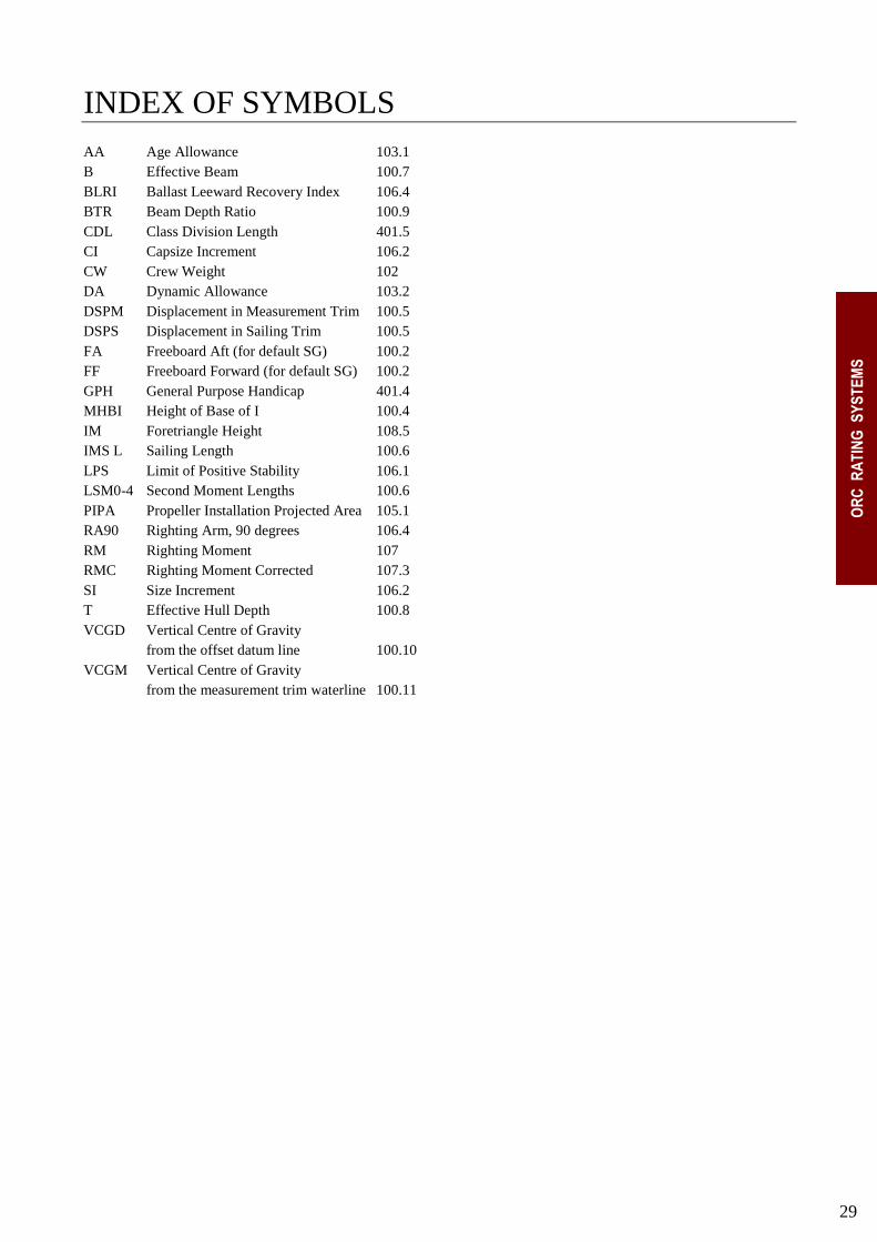
INDEX OF SYMBOLS AA Age Allowance 103.1
B Effective Beam 100.7
BLRI Ballast Leeward Recovery Index 106.4
BTR Beam Depth Ratio 100.9
CDL Class Division Length 401.5
CI Capsize Increment 106.2
CW Crew Weight 102
DA Dynamic Allowance 103.2
DSPM Displacement in Measurement Trim 100.5
DSPS Displacement in Sailing Trim 100.5
FA Freeboard Aft (for default SG) 100.2
FF Freeboard Forward (for default SG) 100.2
GPH General Purpose Handicap 401.4
MHBI Height of Base of I 100.4
IM Foretriangle Height 108.5
IMS L Sailing Length 100.6
LPS Limit of Positive Stability 106.1
LSM0-4 Second Moment Lengths 100.6
PIPA Propeller Installation Projected Area 105.1
RA90 Righting Arm, 90 degrees 106.4
RM Righting Moment 107
RMC Righting Moment Corrected 107.3
SI Size Increment 106.2
T Effective Hull Depth 100.8
VCGD Vertical Centre of Gravity
from the offset datum line 100.10
VCGM Vertical Centre of Gravity
from the measurement trim waterline 100.11