world i ntelhttcrnalionallectllalpropertyburcau ... · embodiment ofthe inventions described in...
TRANSCRIPT
(12) INTERNATIONAl, APPIACATION PUBI.ISHEI) UNDER THE PATENT COOPERATI(JN TREATY (PCT)
(I 9) Worl d I ntelhttcrnalionallectllal PropertYBurcau Organization @ IIIIII IIIIIIII II IIIIII IIIII IIIII IIIII IIIIIII III IIIII IIIII IIIII IIIII IIIII IIII IIIIIII IIII III IIII (43) International Publication Date (10) International Publication Number
20 July 2006 (20.07.2006) PCT WO 2006/074515 A1 (51) In~rnational Patent Classillcation: (81) Designated States (urlle~s othe~wixe indicated, .fi)r every
A61M 16/06 (2006A11) A62B 9/06 (2006.01) kind ~f national protection mailable): AI!, AG, AI,, AM,
AT, AU, AZ, BA, BB, BG, BR, BW, BY, BZ, CA, CII, CN, (21) InOernational Appllcathm Number: CO. CR, CU, CZ, DE DK, DM DZ EC EE EG ES, FI
PC’I/AU20061000034 GB. GD GE GH, GM, HR. HIY, ID. IE, IN IS. IP, KE
(22) I n~rnational Filing Date: 12 January 2006 (12.01.2006) LY, MA, MD, MG, MK, MN, IVIW, MX, MZ, NA, NG, NI,
(25) lqli~ug Language: English NO, NZ, OM, PG, PII, PL, PT, RO, RU, SC, SD, SE, SG, SK. SL. SM. SY. TE TM. TN. TR TT. TZ UA UG. US
(26) Publication Eanguage: English UZ, VC, VN, YU, ZA, ZM, ZW.
84) Designated States (unless otherwise btdicated, jbr every (30) Priority Data: Idnd qf regional protection available): ARIPO (BW, GH,
(71) Applicant (fi)ralldeqignatedStates except US): RESMED ZW), Era’asian (AM, AZ, BY, KG, KZ, MD, RU, TJ, TM),
IAMITE]) I AU/AU l; 1 lilizabeth Macarthur I)rive, Be]la European (AT, BE, BG, CII, CY, CZ, DE, DK, EE, ES, FI,
Vista, New South Wales 2153 (AU). FR, GB. GR H13 IE IS IT ET. LU. EV. MC, NL PL PT
(72) Inventors; and GN, GO, GW, ML, MR, NE, SN, fD, IG).
(75) Inventors/Applicants tfor US only): EIITCHCOCK, Declaration under Rule 4.17: Robin, Garth [AU/AU]; C/- 1 Elizabeth Macarthur Drive, of invento rship (Rule 4.17(iv)) Bella Vista. New South Wales 2153 (AU). DAVIDSON,
Published: Aaron, Samuel IAU/AUI; C! 1 Eli/abeth Macarthur
Drive, Bclla Vistas, New South W~dcs 2153 (AU). For lwo lette~ codea and other abbreviationa, refe~ to ltd. "Guid
(74) Agents: DAVIDSON, Geoffrey, Robert et ah; IIalford & anceNoteaonCodeaandAbbrevialions"appearingaltlwbegin
Co. [ Market Street Sydney New South Wales 2000 (AU). ning of each regulat issue ~’the PCT Gazette.
(54) Title: RESPIRATORY MASKS WITH GUSSETED CUSHIONS
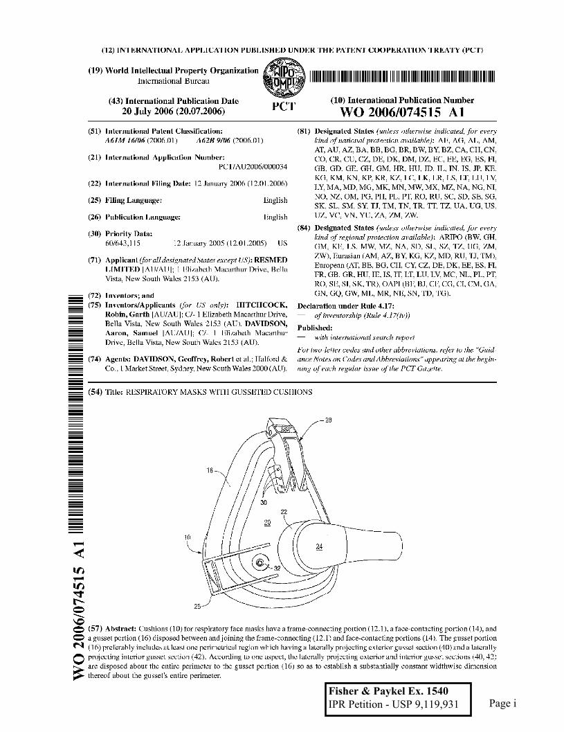
(57) Abstract: Cushions (10) for ~esph’atory face masks have a li’ame connectin~ portion (12.1), a face contacting portion ( 14}, and
a gu sset portion (16) disposed hetween and j oini~g the f~ame-connectiug (t~. 1] and face-contacting portions (t4). The gusset potion
l m’c disposed about the entire pefimctc~ to the gusset lyortion (16) so ~LS to establish a subst~tially constaqt widthwisc dimension thereof about the gusset’s entire perimeter.
Page iFisher & Paykel Ex. 1540 IPR Petition - USP 9,119,931
WO 2006/074515 PCT/AU2006/000034
RESPIRATORY MASKS WITH GUSSETED CUSHIONS
CROSS-REFERENCE TO RELATED APPLICATIONS
[0001] This application claims the benefit of U.S. Provisional Application No.
60/643,115, filed January 12, 2005, the entirety incorporated herein by refe~ance.
[00021 Also, PCT Application No. PCT!AU2005/000850, filed June 15, 2005, is
expressly incorporated hereinto by reference in its entirety.
FIELD OF THE INVENTION
[00031 The present invention relates generally to the field of masks used for
respiratory therapy. In especially preferred embodiments, the present invention relates to
respiratory masks having a gusseted cushion.
BACKGROUND OF THE INVENTION
[0004] Facial masks are well lmo~vn for’use in continuous positive airway
pressure (CPAP) treatment of various respiratory ailments and sleep disordered breathing
(SDB), such as, for example, obstructive sleep apnea (OSA) and!ur other ventilatory
assistance treatments such as noninvasive positive pressure ventilation (NPPV). See, for
example, U.S. Patent No. 4,944,210, the entire content of ~vhich is expressly incorporated
hereinto by reference. While the present invention will be described below with reference
to a full facial mask for use in CPAP treatment, it will be understood that such a reference
is non-limiting mad is directed toward a particularly preferred embodiment of the present
invention. Thus, the various characteristics and advantages of the present invention could
equivalently be embodied in another type of mask, such as a nasal mask, or another type
of NPPV therapy.
1
Page 1

WO 2006/074515 PCT/A [J2006/0001~34
[0005] Apparatus for the treatment of SDB generally involves a blower which
delivers a supply of air at positive pressure to a patient interface via a conduit. The
patient interface may take several forms, such-as a nasal m~k assembly and a nasal and
mouth mask assembly (i.e., a full face mask). Patients typically wear a mask assembly
while sleeping to receive the NPPV therapy.
[0006] Mask assemblies typically include a rigid shell or frame and a soft face-
contacting cushion. The cushion cusl~ions the rigid frame from the patient’s face, end
provides a seal with the patient’s face. The frame and cushion define a cavity which
receives the nose or nose and mouth. The frame.and cushion are held in position on the
patient’s face by a headgear assembly. The headgear assembly typically comprises an
arrangement of straps which pass along both sides of the patient’s face to the back or
crown of the patient’s head.
[0007] One problem that arises with existing masks used tbr CPAP treatments is
that over-tightening of the mask straps results in compression of the mask against the
wearer’s face which may therefore apply undue pressure force against certain of the
wearer’s facial features, such as the wearer’s nose. A poorly fitting mask can leai~ when
pressurized which encourages a patient to tighten the headgear straps excessively which,
in turn leads to discomfort, marks on the face and in some cases facial sores.
[0008] The cushion of a patient mask interface can play a key ioie in the comfort
an~t effectiveness of therapy. The nasal bridge area of the patient!s face has been
identified as being particularly sensitive and thus a mask design needs to pay particular
attention to such region.’
10009] ’The issue of mask comfort and effectiveness is particularly apparent when
treatment pressure varies, for example, when a patient uses an automatic positive airway
pressure (APAP).device such as those commercially available from ResMed Limited
Page 2

WO 2006/074515 PCT/A [J2006/0001134
under the tradename AUTOSET. When the pressure varies, patients may set the headgear
tension for the highest pressure, which thereby leads to unnecessarily high tension being
experienced at lower pressures.
[1101111 To address such problems, mask systems that vary the sealing force with
treatment pressure have been developed, including a nasal mask cushion having a gusset
portion, as evidenced by U.S. Published Patent Application 2002/0029780; U.S: Patent
No. 6,772,760 and U.S. Published Patent Application US 2004/0118406, the entire
eo.ntent of each being expressly incorporated hereinto by reference. A commercial
embodiment of the inventions described in such patent publications is the ACTIVATM
mask system available from ResMed Limited.
[00111 U.S. Patent No. 5,074,297 (the entire content of which is expressly
incorporated hereinto by reference) describes a respiratory mask assembly for use with
intermittent positive pressure breathing treatment and is said to facilitate the formation
and automatic adjustment of the seal between a patient’s face and a facial unit of the
respiratory mask.
1011121 While the prior proposals for adjustable mask cushions may be satisfactory
for their intended purposes, improvements are still needed, especially for a full face mask
patient interface.
SUMMARY OF THE INVENTION
[0013] Broadly, one embodiment of the present invention is directed to full t~ace
masks fro" use in respiratory therapy wherein a gusset portion is interposed between the
mask cushion and the mask frame. The gusset portion thereby allows for relative
movement of the mask frmne to occur towards and away from a patient’s face to ensure
Page 3

WO 2006/074515 PCT/A [J2006/0001134
the integrity of sealing contact between the cushion and the patient’s facial features and to
maintain a desired comfort level.
[0014] The gusset portion in accordance with the present invention provides
several benefits. For example, the gusset portion utilizes the pressure in the mask acting
on its increased surface area to provide a force to maintain the face-contacting portion of
the cushion in sealing contact with the patient’s face. Of course, the gusset may include a
predetermined spring constant that can also affect the force applied to seal against the
user’s skin. Additionally, the gusset portion provides in effect a decoupling joint between
the face-contacting portion of the cushion and the mask shell thereby allowing some
relative movement to occur between the mask and the cushion contacting the patient’s
face. This an’angement substantially protects the seal from undue disturbance when the
mask or mask shell is tilted; the facial muscles are relaxed, patient movement occurs,
and/or movenaent of the gas supply tube occurs. This decoupling joint provided by the
gusset also allows additional travel between the mask shell and the lower cushion which
reduces the precision by which the strap length must be maintained.
[00151 Tile gusset portion of the present invention is especially beneficial in the
context of a full face mask since it has at least one perimetrical section which includes
generally laterally projecting exterior and interior gusset sections. Both laterally
extending exterior and interior gusset sections provide flexibility and increase the
allowable travel of the mask frame from the cushion. The laterally projecting exterior
section also provides additional sealing pressure to the cushion depending on treatment
pressure. Most preferably, the incorporation of the laterally exterior projecting gusset
section increases the projected surface area on the patient’s face by at least about 260%
compared to the projected surface area of the face-contacting portion of the cushion
alone. For example, in an embodiment, the projected surface area of the face-contacting
4
Page 4

WO 2006/074515 PCT/A [J2006/0001134
portion alone is about 50cm2 and the projected surface area of the gusset section alone is
in the range of 30-90em2, preferably about 80cm2. Thus, the gusset section adds about
80cm2 extra area to the cushion or about 160% (80/50) extra area compared to the cushion
alone. As a result, the total projected surface area of the gusseted cushion is equal to the
summation of the face-contacting portion and the gusset section which is in the range of
80-140cm2, preferably about 130cm2 (80+50), and this total area is about 260% (130/50)
of the projected surface area of the face-contacting portion alone.
[0016] One aspect of the gusseted cushion according to the present invention is
the ga’eater projected area that may be achieved in a particular facial region of the patient
which leads to additional sealing force per unit mask pressure that may be obtained at
such region. By varying the widthwise extent that the gusset projects laterally outwardly
around the perimeter of the mask, the mnount of pressure-dependent additional sealing
force can be varied since pressure acts upon the additional area from the sealing point of
the cushion on the face to the exterior of the gusset and provides a force on the cushion.
For example, according to an aspect of the present invention, the sealing force may be
reduced in sensitive facial areas of the patient, Such as the region of the patient’s nasal
bridge by reducing the widthwise extent of the gusset in this region.
[0017] The anaount of additional area that the laterally outwardly extending gusset
is required to project is also dependent upon the treatment pressure. A relatively large
area Ag (e.g. 300 cmz when compared to the projected area of the cushion A~ of 50era2,
see Fig. 8) might form a suitable seal at a low pressure of abont 4 emiliO, but may be
excessive at about 20 cmH20. The overall sealing pressure on the cnshion is a
combination of the strap tightness mad the additional area projected outside the sealing
point of the cushion. It has been found that an overall sealing pressure of about 3 kg total
force on the entire cushion seal applies excessive force to the patient and hence a
5
Page 5

WO 2006/074515 PCT/A [J2006/0001~34
projected gusset area should be such that the overall seaiing pressure is less than 3 kg.
More specifically, the width oft he gusset should have a preferred projected area A~ onto
the patient’s face of approximately 130 cm2 when the invention is embodied in a full face
mask.
[0018] Another aspect of the gusset is the travel available in a particular patient
facial region. Travel allows movement to occur between the frame contacting portio~ and
the patieut contacting portion of the cushion between which the gusset is disposed. In
general, a cushion in accordance with the invention allows substantially the same mount
of travel around the entirety of the cushion’s perimeter so that the frame mad patient
contacting portions can remain generally parallel. This is achieved by varying the width
of the interior projecting gusset or gussets to maintain the anaount of travel regardless of
the width of the exterior projecting gusset which is tailored to meet the particular sealing
force requirements of the facial region. In use there may in fact be non-parallel travel
movement of the frame relative to the patient’s face due to the inherent flexibility of their
material of construction. In this regard, the gusseted cushions of the present invention
most preferably provide between about 5 mm to about 25 ram, advantageously about
16ram (+/- 1 ram), of travel distance when embodied in a full face mask.
[0019] The present invention may be embodied in a cushion for a respiratory
mask assembly having a frame-connecting portion, a face-contacting portion, and a gusset
portion disposed between and joirthag the frame-cormecting and face-contacting portions:
The gusset portion preferably includes at least one perimetrical region which has a
laterally projecting exterior gusset section and a laterally projecting interior gusset
section.
[0020] According to one aspect, the laterally projecting exteriur and interior
gusset sections are disposed about the entire perimeter to the gusset portion so as to
6
Page 6
WO 2006/074515 PCT/A [J2006/0001134
establish a substantially constant widthwise dimension thereof about the gusset’s entire
perimeter. According to another aspect, the laterally projecting exterior and interior
gusset s~ctions of the gusset pro.iect only along a lower perimelrieal region thereof so that
the gusset portion has a widthwise dimension which varies aloout its perimeter.
[0021] In mother aspect, the gusset portion has a minimum widthwise dimension
at an upper perimetrical region thereof, a maximum widthwise dimension at a lower
perimetlical region thereof, and widthwise transitions joining said upper and lower
perimetrical regions thereof. The widthwise transitions may be either curvilinear or
linear.
[0022] Another aspect of the present invention is a cushion for a respiratory ma~k
having a frame-conneeting portion, a face-enntacting portion, and a gusset portion
disposed between and joining the franae-conneeting and face-contacting portions, wherein
said gusset portion has a perimeter with a widthwise dimension which varies between at
least one region and another perimetrical region thereof. In a preferred aspect, the gusset
portion has a minimum widthwise dimension at an upper perimetrical region _thereof, a
illaxinaum widthwise dimension at a lower perimetrical region thereof, and widthwise
transitions (which may be cmwilinear or linear) joining such upper and lower perimetrical
regions thereof.
[0023] In one specific aspect, the cushion of the present invention substantially
zero widthwise dimension at said upper perimetrical region thereof. In accordance with
another aspect of the invention, each of the minimum mid maximum widthwise
dimensions is substantially constant along the upper and lower perimetrical regions,
respectively.
[0024] According to another aspect, the invention has an upper perimeter region
which occupies between about 15%to about 30% of the entire perimeter of the cushion, a
7
Page 7

WO 2006/074515 PCT/A [J2006/0001134
lower perimeter region which occupies between about 50% to about 70% of the entire
perimeter of the cushion, and transition regions which occupy between about 10% to
about 30% of the entire perimeter of the cushion.
[0025[ These and other aspects and advantages will become more apparent after
careful consideration is given to the following detaiied description of the preferred
exemplary embodiments thereof.
BRIEF DESCRIPTION OF THE DRAWINGS
[0026] Reference will hereinat~er be made tO the accompanying drawings,
wherein like reference numerals throughout the various FIGURES denote like structural
elements, and wherein:
[00271 FIGURES 1-1 to 1-4 show various views of a full facial mask assembly
providing patient interface for respiratory therapy having an embodiment of a gusseted
cushion according to the present invention, wherein FIGURE 1-1 is a front plan view
thereof, FIGURE 1-2 is a front perspective view thereof, FIGURE 1-3 is left side
elevational view thereof, and FIGURE 1-4 is a rear perspective view thereof;
[00281 FIGURE 2 is a schematic partial rear plan rear view (patient side) of a
gusseted cuslfion employed in the face mask assembly depicted in FIGURES 1-1 to 1-4;
[00291 FIGURE 2-1 is a cross-section of the cushion depicted in FIGURE 2 as
taken along line A-A therein;
[0030] FIGURE 2-2 to 2-4 are alternative cross-sections of the cushion depicted
in FIGURE 2 as taken along line A-A therein;
[0031] FIGURES 3-1 to 3-3 show various views of a full face mask assembly
providing patient interface for respiratory therapy having another embodiment of a
gusseted cushion according to the present invention, wherein FIGURE 3-1 is a front plan
8
Page 8

WO 2006/074515 PCT/A [J2006/0001~34
view therenf, FIGURE 3-2 is a front perspective view thereof, FIGURE 3-3 is right side
elevational view thereof;
[00321 FIGURE 4 is a schematic partial rear plan rear view (patient side) of a
gusseted cushion employed in the mask assembiy depicted in FIGURES 3-1 to 3-3;
[0033] FIGLrR_ES 4-1 and 4-2 are cross-sections of the cushion depicted in
FIGURE 4 as taken along lines A-A and B-B therein, respectively;
[0034] FIGURES 4-3 to 4-5 are alternative cross-sections of the cushion depicted
in FIGURE 4 as take along line A-A therein;
[0035] FIGURES 5-1 to 5-3 are various views of a gusseted cushion accordLng to
another embodiment of the present invention, wherein FIGURE 5-1 is a top elevation
view thereof, FIGURE 5-2 is a right side elevation view thereof, and FIGURE 5-3 is a
bottom elevation view thereof;
[0036] FIGURE 6 is a schematic partial rear plan rear view (patient side) of the
gusseted cushion depicted in FIGURES 5-1 to 5-3;
[0037] FIGURES 6-1 to 6-8 are various cross-sections of the cushion depicted in
FIGURE 6 wherein, FIGURE 6-1 is a cross-sention taken along line G-G therein;
FIGURE 6-2 is a cross-section taken along line A-A therein; FIGURE 6-3 is a cross-
section takan along line F-F therein; FIGURE 6-4 is a cross-section taken along line E-E
therein; FIGURE 6-5 is a cross-section taken along line D-D therein; FIGURE 6-6 is a
cross-section taken along line B-B therein; FIGURE 6-7 is a cross-section taken along
line C-C therein; and FIGURE 6-8 is a cross-section taken along line H-H therein;
[00381 FIGURE 7 is a plot of sealing force (Kg) on a patient’s face from the
cushion versus displacement distance of the mask frame towards the patient’s face (i.e.,
from a fully expanded state of the gusset to a fully compressed state of the gusset);
Page 9

WO 2006/074515 PCT/A [J2006/0001134
[0039] FIGURE 8 is a schematic view illustrating the relation between the
projected area of the gusset Ag and the projected area of the face-contacting portion of the
cushion Ao; and
[0040] FIGURES 9A-9Y are partial schematic views according to further cushion
embodiments of the present invention.
DETAILED DESCRIPTION OF PREFERRED EMBODIMENTS
First Cushion Embodiment
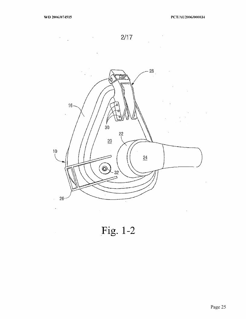
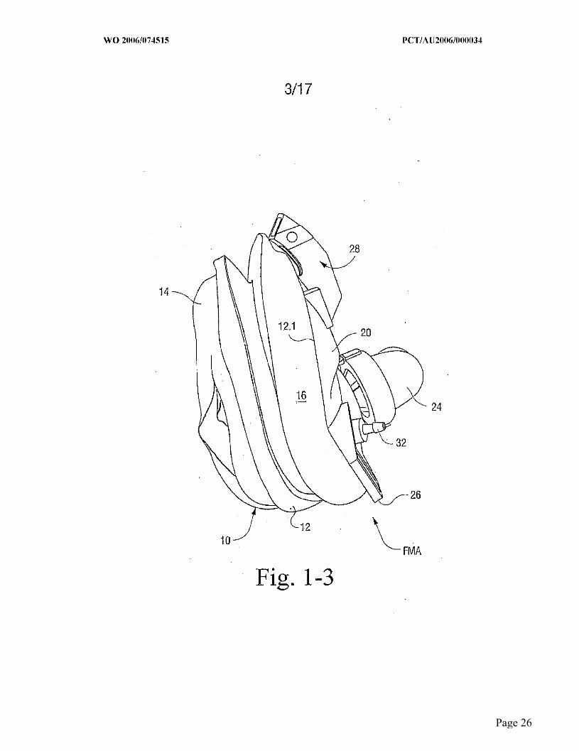
[0041] An exemplary embodiment of a full facial mask assembly FMA which
includes a gusseted cushion 10 according to one embodiment of the present invention is
depicted in accompanying FIGURES 1-1 to 1-41 The mask assembly FMA includes a
mask frame 20 provided with a connection port 22 to which an elbow connector 24
associated with a gas supply conduit may be coupled to allow breathable gas under
pressure to be supplied to the mask assembly FMA. The cushion 10 includes distal mask-
colmecting poltiou 12.1 which cormects the cushion 10 to the mask frame 20, a proximal
face-contacting portion 14 and an intermediate gusset portion 16 is between or joining the
distal and proximal portions 12.1, 14, respectively. The mask cushion 10 may also
include a reintbrcing member 12 that supports one or more sidewalls of the cushion
towards the face-contacting portion 14.
[0042] Strap colmeetors 26 extend laterally from the mask frame 20 so as to allow
attachment of straps associated with a conventional headgear assembly (not shown) and
thereby permit the mask assembly FMA to be secured to a wearer’s head when in use.
The mask frame 20 may also be provided with a receiver 28 which is adapted to receive a
slide bar associated with a forehead support assembly (not shown), for example, a
forehead support assembly of the variety disclosed in commonly owned U.S. Provisional
10
Page 10

WO 2006/074515 PCT/A [J2006/0001134
Patent Application Serial No. 60/735,823, filed November 14, 2005, the entire content of
which is expressly incorporated hereinto by reference. A number of vents 30 may be
provided so as to allow gas exhaled by the patient to vent to atmosphere. In addition, an
auxiliary port 32 may be provided so as to allow the introduction of an auxiliary
breathable gas to the mask interior as may be desired, or the port 32 may allow for the
measure of pressure within the interior of the mask.
[110431 Accompanying FIGURE 2 and the cross-section thereof as depicted in
FIGURE 2-1 show one embodiment of the gusset portion 16 in accordance with the
present invention. (Note that FIGURE 2-1 does not include reinforcement member 12.)
In this regard, the footprint area of the full face mask is generally triangular with the apex
thereof at the bridge region of the patient’s nose and a base region located generally
between the patient’s mouth and chin regions. The cushion 10 is similarly triangularly
shaped. As sho~vn in FIGURE 2, the gusset portion 16 has a substantially constant cross-
sectional configuration as depicted in FIGURE 2-1 about its entire perimeter. Stated
another way, the gusset portion 16 has a substantially constant lateral dimension about the
entirety of its generally triangular perimeter which thereby projects a substantially
constant cross-sectional area onto the patient’s face.
[11044] In the embodiment depicted in FIGURE 2 and the cross-section thereof
depicted in FIGURE 2-1, the gusset portion 16 is in the form of an accordion fold having
a laterally projecting exterior gusset section 40 and a laterally projecting interior gusset
section 42. The laterally projecting exterior and interior gusset sections 40, 42 thus
establish respective widthwise dimensions We, Wl which in use establish the amount of
travel and flexibility the gusset provides. The dimension W relating to the exterior gusset
section (measured from the cushion contact point to the exterior of the gusset) establishes
an area projected on the patient’s face Ag which is about 130crn~ or about 260% greater
11
Page 11
WO 2006/074515 PCT/A [J2006/0001134
than the projected surface area (about 50cm2) of the face-contacting portion of the
cushion Ac alone as shown in Fig. 8. For example, in an embodiment, the projected
surface area of the face-contacting portiou Ae alone is about 50era2 and the projected
surface area of the gusset section (A~- Ac) alone is in the range of 30-90em2, preferably
about 80era2 as shown in Fig. 8. Thus, the gusset section adds about 80em~ extra area to
the cushion or about 160% (80/50) extra area. As a result, the total projected surface area
of the gusseted cushion A~ is equal to the summation of the face contacthig portion and
the gusset section wltich is in the range of 80-140cm2, preferably about 130cm2 (80+50),
and this total area is about 260% (130/50) of the projected surface area of the face-
contacting portion of the cushion Ac alone. These dimensions are exemplary in natare to
demonstrate the relevant projected areas.
[0045] It is to be understood that the projected surface areas and associated
percentage calculations described herein are merely exemplary and other sizes and
percentages are possible depending on application. For example, the sizes and
percentages described above may be for a medium sized gusseted cushion, and the sizes
and associated percentage calculations may be applied proportionally to other sized
cushions, e.g., extra small, small, and large.
[0046] It ~vill be observed that the gusset portion 16 according to the embodiment
depicted ha FIGURE 2 includes, in order from the mask connecting portion 12 toward the
t~ace-contacting portion 14, the exterior gusset section 40 extending generally laterally
outwardly and terminating at an exterior tip section 44, a connecting gusset section 46
extending from the tip section 44 generally inwardly and terminating at an interior tip
section 48, and the interior gusset section 42 extending generally laterally from interior
tip section 48 to the base 14.1 of face-contacting portion 14.
12
Page 12

WO 2006/074515 PCT/A [J2006/0001134
. [0047] Accompanying FIGURES 2-2 to 2-4 depict alternative cross-sections that
may be provided with the gusset portion 16. In this regard, any one cross-section or
combination of cross-sections depicted in FIGURES 2-2 to 2-4 may be employed.
[0048] It will be observed in FIGURE 2-2 that the thickness of each gusset
section 40, 42 and 46 is substantially thicker as compared to the embodiment shown in
FIGURE 2-1. Preferably, the sections 40, 42 and 46 of the gusset portion 16 shown in
FIGURE 2-2 have a substantially uniform thiclmess of between about 0.5 mm to about
1,0 mm, whereas the thickness of such comparable sections sho~vn in FIGURE 2-1 is
about 0.5 mm or less.
[0049] Alternatively or additionally, the extremities of the sections 40 an~ 42
where each joins the mask-cormecting portion t2 and the face-coxatacting portion 14,
respectively, may be thickened as shown in FIGURE 2-3. Again, alternatively or
additionally, the inverted portion of the tip section 44 and the everted portion of the tip
section 48 may include a thickened region as shown in FIGURE 2-4. The relative
thickness of the tip sections 44 and/or 48 may thus be varied as compared to the sections
40, 42 and 46 by the mask designer to achieve desired functions, such as the resiliency or
amount of spring force inherently possessed by the gusset portiun 16.
Second Cushion Embodiment
[0050] A full ~aciaI mask assembly FMA employing another embodiment of a
gusseted cushion 10A in accordance with the present invention is depicted i£ FIGURJ~S
3-1 to 3-3 and FIGURES 4, 4-1 and 4-2. In this regard, structural components that are
similar to those discussed previously have been shown with the same reference numerals.
Thus, a detailed discussion of such similar structural components will not be repeated.
13
Page 13

WO 2006/074515 PCT/A [J2006/0001134
[0051] As can be seen in FIGURE 4, the gusseted cushion 10A has gusset section
16A provided with a relatively narrow or constant width region 16-1 from a location P 1
adjacent a patient’s nose mad around the patient’s nasal bridge region. The gusset section
16A also has a maximal width region 16-2 fi’om a location P2 generally adjacent a
patient’s mouth region around the base of the cushion 10A. In this regard, compare the
width dimensions W1 and W2 (i.e.0 defining respective projected areas) shown in
FIGURE 4 for each 0fthe regions 16-1 and 16-2, respectively. The width dimensious
W1 and W2 are measured from the cushion contact point to the exterior of the gusset. A
transition region 16-3 curvilinearly joins the regions 16-1 and 16-2 between points P1 a~d
P2.
[0052] The non-uniform width regions W1 and W2 thus have the benefits of
providing less visual obstruction near the eye region of the patient and less force applied
at the patient’s nasal bridge region due to the presence of the minfl~al width region W1
thereat. In addition, the center of the applied force against the patient’s face is positioned
lower as compared to the substantially co~ast~t width gusseted cushion 10 as discussed
previously due to the greater projected width area being located physically lower in the
gusseted cushion 10A.
[0053] ~hus, as depicted in FIGURE 4-1 there is little or no projected area in the
gusset in the nasal bridge region, although travel of the cushiordfi’ame is still pemaitted
due to its generally W-shaped or concertina-type fold establislxing a pair of exterior gusset
sections 50, 52 cormected to one another at a tip section 53, and a pair of interior gusset
sections 54, 56 connected to the gusset sections 50, 52 at tips 57 and 59, respectively.
However, in contrast, the gusset cross-section depicted in FIGURE 4-2 has substantially
greater width W2 due to the generally sinusoidal shape of the gusset section 16-2 thereof,
14
Page 14

WO 2006/074515 PCT/A [J2006/0001134
and hence a substantially greater projected area onto a patient’s face as compared to the
width W1 of gusset section 16-I near the patient’s nasal region.
[0054] Accompanying FIGURES 4-3 to 4-5 depict alternative cross-sections that
may be provided with the gusset poltion 16A. In this regard, cross-sections depicted in
FIGURES 4-3 to 4-5 may advantageously be employed in gusset ~ections 16-1 and/or 16-
3 so as to provide for the desired degree of relative resiliency thereof. Moreover, any one
cross-section or eomhination of cross-sections as depicted in FIGURES 4-3 to 4-5 may be
employed as desired.
[0055] In FIGUR~ 4-3 it will be observed that the thickness of the tip section 53
is ~’eater as compared to the other tip sections 57 and 59..Alternatively or additionally,
the extremities of the apex of tip sections 57 and 59 may each be thickened relative to the
other gusset sections as shown in FIGURE 4-4. Again, alternativeIy or additionally, each
gusset section 50-59 according to the’alternative cross-sectlon depicted in FIGURE 4-5 is
substantially thicker as compared to the embodiment shown in FIGURE 4-1. In this
regard, the thickness of sections 50-59 depicted in FIGURE 4-5 is preferably between
about 0.5 mm to about 1.0 mm, whereas the thickness of such comparable sections shown
in FIGURE 4-1 is about 0.5 mm or less.
Thh-d Cushion Embodiment
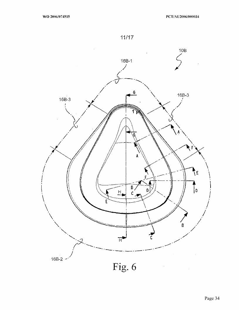
[0056] Another embodiment of a gusset cushion 10B in accordance with the
present invention is depicted in FIGURES 5-1 to 5-3, FIGURE 6 and the cross-sections
thereof shown in FIGURES 6-1 to 6-8. In this regard, as is perhaps most clearly shown in
FIGURE 6, the gusset cushion 10B is comprised of upper and lower arcuately shaped
gusset regions 16B-1 and 16B-2 which are joined to one another by a substantially linear
transition region 16B-3.
15
Page 15

WO 2006/074515 PCT/A [J2006/0001134
[0057] As is shown in FIGURE 6 and the eross-sections thereof depicted in
FIGURES 6-1 to 6-8, the gusset 16B in accordance with this further embodiment of the
present invention has a minimal widthwise dimension around the upper (nasal bridge)
region 16B-1, and a substantially constant maximarn width along the lower region 16B-2
which extends substantially from one cheek bone area of the patient to the other.
Substantially linear (straight) side regions 16B-3 from generally the nasal bridge area to
each cheek bone area of the patient provide widthwise transition sections from the
minimal width thereof at upper region 16B-1 to the maximum Width thereof at lower
region 16B-2. Most preferably, the upper region 16B-1 occupies between about 15% to
about 30% of the cushion’s perimeter distance, and lower region 16B-2 occupies between
about 50% to about 70% of the cushion’s perimeter distance, with side regions 16B-3
occupying the remainder perimeter distance.
[0058] The projected area of the gusset 16B, Ag, is prefarably betwecu about 80
emz to about 140 cm2, more preferably approximately 130 cua2, as measured in its natural
molded state O.e., uncompressed). Of course, the area could be higher or lower,
depending on application. In this regard, since little additional sealing force is required in
the nasal bridge region, the upper gusset region 16B-1 does not necessarily require a~y
projected area, hence the zero or near zero width in that region. Moreover, the
substautially straight side regions impart structural stability to the gusset 16B in the upper
region 16B-I. Also, the gusset 16B in the nasal bridge region has a generally w-shaped
cross-sectional configuration (see Fig. 6-1) which may provide spring-like characteristics
in use.
[0059] It will be observed in the cross-sections of FIGURES 6-1 to 6-8 that the
gusset 16B has the same travel distance towards and away from the patient’s face due to
the fact that the gusset 16B has the same effective dimension in the travel direction at any
16
Page 16

WO 2006/074515 PCT/A [J2006/0001134
perimetrical location. However, at different perimetrical locations, the exterior and
interior lateral projections thereof will vary so as to achieve the minin~al width dimension
along the upper region 16B-1 (see FIGURE 6-1), and the maximum width dimensions
along the lower region 16B-2 (see FIGURES 6-5 to 6-8). Widthwise transitions will
however be present along the side regions 16B-3 (see FIGURES 6-2 to 6-4).
[0060] FIGUI~ 7 is a plot of sealing force (Kg) on a patient’s face due to contact
with cushions in accordance with the present invention versus displacement distance of
the mask frame towards the patient’s face O.e., fi:om a fully expanded (open) travel state
of the gusset to a fully compressed state(closed) travel state of the gusset. As is seen, the
target travel window of 16 mm (+/- 1 mm) achieved by the gussets of the present
invention dramatically flatten the pressure curve so as to maintain comfort for the patient
and reduce the importance of a particular strap length setting on sealing performance.
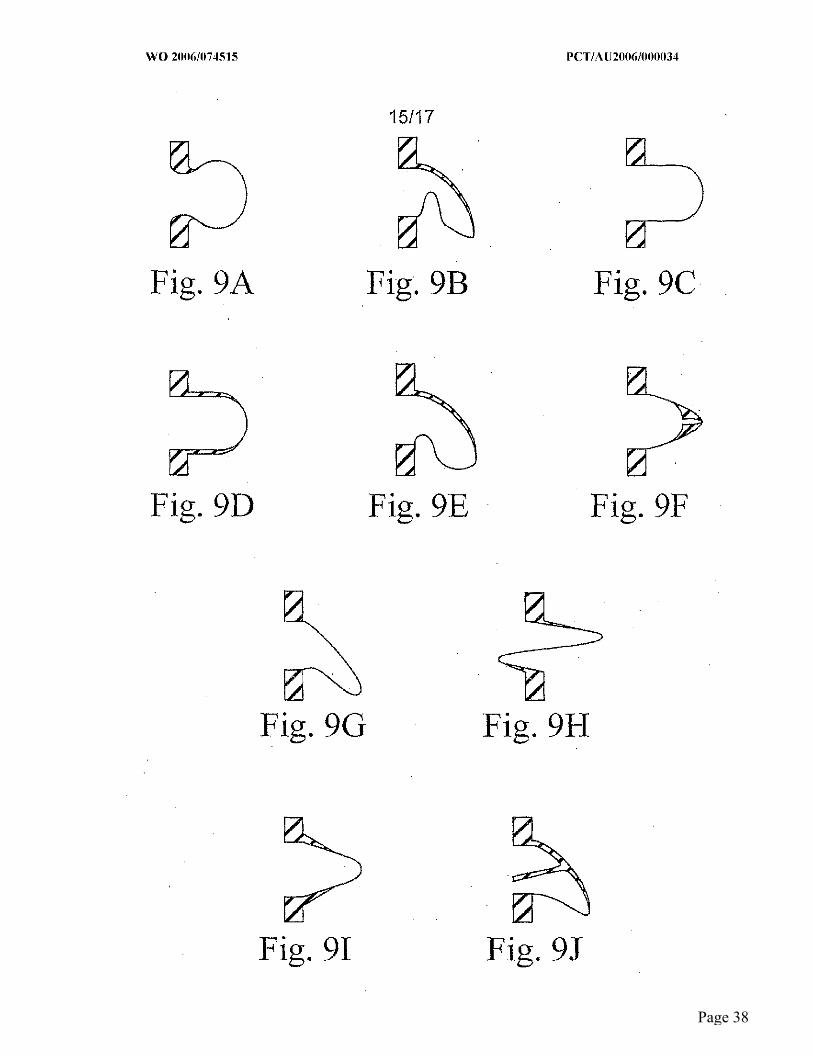
[0061] Figs. 9A-9Y illustrate further embodiments according to the present
invention. Fig. 9Y schematically illustrates a partial section of a mask assembly 800
having a cushion including a face contacting/interacting portion 802 that may include a
membrane 804 with an optional tmder134ng rim 806. Cushion includes a non-face
contacting portion 808 that is supported by a frame 810. A central portion 812, in the
form of a black box, is provided between portions 806 and 808.
[0062] Figs. 9A-9X illustrate various central portions ttmt can be used for control
portion 812 in Fig. 9Y. In the case of Figs. 9N and 9R, face-contacting interacting
portion 808 and/or frame 810 (Fig. 9Y) would be adjusted, e.g., widened, to
acenmmodate for illustrated offset. Various features of Figs. 9A-9X are tabulated below
in Table 1.
17
Page 17

WO 2006/074515 PCT/A [J2006/0001~34
TABLE 1
Drawings Conu~aent
Fig. 9A Circular moss-section. Provides more travel for the same outer area. The
cii’cnlar shape wilI deform less when pressurized, therefore outer area
remains constant.
Fig. 9B Underside notch has dual purpose. On extension provides more travel
(longer path length), on compression acts as spring. Upperside is tapered
wall section.
Fig. 9C Circular cross-section at end of straight gusset. Provides more travel for
he same outer area. The circular shape will deform less when pressurized,
therefore outer area renaains constant.
Fig. 9D Like Fig. 9C, but with tapered or thickened wall section. When
pressurized, the thickened wall section tends to keep the form.
Fig. 9E Underside notch provides more travel on extension. This is assisted by the
thickened upper wall which tends to keep the form. This also allows for a
constant outer area (As).
Fig. 9F In compression, a spring constant is added. In extension, no spring effect
(one-sided spring). This has the advantage of having a spring at low
pressures but not necessarily at high pressures.
Fig. 9G Angled gusset provides more travel for the same outer area.
Fig. 9H Internal gusset provides more travel for the same outer area.
Fig. 9I Thickened section deforms only under higher pressures. At lower
pressures, thickened section will touch when gusset is compressed and act
as spring. This has the advantage of having a spring at low pressures but
not necessarily at high pressures.
Fig. 9J Thickened section deforms only under higher pressures. This moves the
~ spring tab away fi:om the lower section (i.e., no spring). At lower
pressures, spring tab will touch when gusset is compressed and act at
spring. This has the advantage of having a spring at low pressures but not
necessarily at high pressures.
Fig. 9K Thickened section will not deform under pressure, maximizes outer area
with respect to Fig. 9G. Angled gusset also provides for more travel for
the same area.
18
Page 18

WO 2006/074515 PCT/A [J2006/0001134
Drawings Colmnent
Fig. 9L Double gusset provides more travel for the same outer area.
Fig. 9M Spring element added.
Fig. 9N Attacbanent point moved outwards. Outer area maintained fixed.
Underside notch provides more travel (longer path length).
Fig. 90 In compression, a spring constant is added. In extension, no spring effect
(one-sided spring). Note: Similar to but more spring and less expansion
of the gusset at high pressures.
Fig. 9P ~ Angled gusset provides more travel for the same outer area.
Fig. 9Q In compression, a spring constant is added. In extension, no spring effect
(one-sided spring). Similar to Fig. 9F, this has the advantage of having a
spring at low pressures but not necessarily at high pressures.
Fig. 9R Attachment point moved outwards. Outer area maintained fixed. Shape
of gusset provides more travel (longer path length).
Fig. 9S Spring effect in extension. No spring effect in compression. Thick walls
provide more constaut outer area under pressure.
Fig. 9T Double internal gusset allows for outer area to be varied from large to
none while still alIowing significant travel.
Fig. 9U This cushion cross-section represents a dh’ect translation of the geometry
of the gusset of the AetivaTM nasal mask onto a full face platform.
Fig. 9V Gusset may be p[ovided around entire perimeter of full face cushion. The
everted gusset does not protrude past the footprint of the cushion.
Fig. 9W Starting with the cushion of Fig. 9U, an inverted gusset has been added to
produce two smailer everted gussets.
Fig. 9X A hanging gusset is provided around entire perimeter of full face cushion.
Gusset molded ~rom an open-shut tool.
Notes: 1 Extension is taken to be movement of frame away from lower cushion
2 Compression is taken to be movement of frame towards lower cushion
3 Travel is taken to be anaount of extension plus compression
4 Outer area is taken to be the outer area of the gusset
19
Page 19

WO 2006/074515 PCT/A [J2006/0001134
[0063] While the invention has been described in connection with what are
presently considered to be th~ most practical and preferred embodiments° it is to be
understood that the invention is not to be limited to the disclosed embodiments, but on the
contrary, is intended to cover various modifications and equivalant arrangements hlcluded
within the spirit and scope of the invention. Also, the various embodiments descriloed
above may be implemented in conjunction "¢¢ith other embodiments~ e.g, aspects of one
embodiment may be combLned with aspects of another embodinaent to realize yet other
embodimants, l_n addition, while the invention has particular application to patiants who
suffer from OSA, it is to be appreciated that patients who suffer from other illnesses (e.g.,
congestive heart failure, diabetes, morbid obesity, slroke, barriatfic surgery, etc.) can
derive benefit fi:om the above teachings. Moreover, the above teachings have
applicability with patients and non-patients alike in non-medical applications.
20
Page 20

WO 2006/074515 PCT/A [J2006/0001~34
WlJAT IS CLAIMED IS:
1. A cushion tbr a respiratory mask assembly comprising a frame-cormecting
portion, a face-contacting portion, and a gusset portion disposed between and joining said
flame-connecting and face-contacting portions, wherein the gusset portion includes at
least one perimetrical region which includes a laterally projecting exterior gusset section
and a laterally projecting interior gusset section.
2. The cushion as in claim 1, wherein the gusset portion has said laterally
prqjecting exterior and interior gusset sections about the entire perimeter to the gusset
portion so as to establish a substantially constant widthwise dimension about said entire
perimeter.
3. The cushion as in claim 1, wherein file gusset portion includes said laterally
projecting exterior and interior gusset sections along a lower perimetrical region thereof.
4. The cushion as in claim 1, wherein the gusset portion has a widthwise
dimension which varies about a perimeter thereof.
5. The cushion as in claim 1, wherein the gusset portion has a minimum
widthwise dimension at an upper perimetrical region thereof, a maximum widthwise
dimension at a lower perimetrical region thereof, and widthwise transitions joining said
upper and lower pefimetrical regions thereof.
6. The cushion as in claim 5, wherein the gusset portion has substantially zero
widthwise dimension at said upper perimetrical region thereof.
7. The cushion as in claim 5, wherein said widthwise transitions are
curvilinear.
8. The cushion as in claim 5, wherein the widthwise transitions are linear.
21
Page 21

WO 2006/074515 PCT/A [J2006/0001~34
9. The cushion as in claim 5, wherein each said minimum and maximum
width~vise dimensions is substantially constant along said upper and lower perimetrieal
regions, respectively.
10. A cushion for a respiratory mask comprising a frame-connecting portion, a
t~ace-contacting portion, and a gusset portion disposed between and joining said frame-
connecting mad face-contacting portions, wherein said gusset portion has a perimeter
having a widthwise dinaension which varies between at least one region and another
perimetrical region thereof.
11. The cushion as in claim 10, wherein the gusset portion has a minimm~a
widthwise dimension at an upper perimetrical region thereof, a maximum widthwise
dimension at a lower perimetrical region thereof, and widthwise transitions joining said
upper and lower perimetrical regions thereof.
12. The cushion as in claim 11, wherein the gusset portion has substantially
zero widthwise dimension at said upper perimetrical region thereof.
13. The cushion as in claim 11, wherein said widthwise transitions are
Curvilinear.
14. The cushion as in claim 11, wherein the widthwise transitions are linear.
15. The cushion as in claim 11, wherein each said minimum and maximum
widthwise dimensions is substantially constant along said upper and lower perimetrical
regions, respectively.
16. The cushion as in claim 11, wherein the upper perimeter region is between
about 15% to about 30% of the entire perimeter of the cushion, the lower perimeter region
is between about 50% to about 70% 0fthe entire perimeter of the cushion, and the
transition regions are about 10% to about 30% of the entire perimeter of the cushion.
22
Page 22

WO 2006/074515 PCT/A [J2006/0001134
17. The cusl~on as ~ claim 16, wherein the gusset portion has substantially
zero widthwise dimension at said upper perimetrical region thereof.
18. The cushion as in claim 16, wherein said widthwise transitions are
carwilLnear.
19. The cushion as in claim 16, wherein the widthwise transitions are linear.
20. The cushion according to any one of claims 1-19, wherein the face
contacting portion and the gusset portion have a projected surface area in the range of 80-
140 em2.
21. The cushion accord~g to claim 20, ~vherein the face contacting portion and
the gusset portion have a projected surface area of about 130era2.
22. A respiratory face mask comprising a mask frame having an inlet for
supplying a breathable gas, and a cushion as in any one of claims 1-21 attached to the
mask frame.
23. The respiratory face mask according to claim 22, wherein the cushiort is
provided in at least four sizes having dJa-~ensions that are proportional to one another.
23
Page 23

WO 2006/074515 PCT/A IJ2006/0001~34
1/17
10
Fig. 1-1
Page 24
WO 2006/074515
2/:17
10
.Fig. 1-2
Page 25
WO 2006/074515 PCT/A IJ2006/0001~34
3/17
28
14
24
Page 26

WO 2006/074515 PCT/A IJ2006/0001~34
4/17
28
26
12 ~ FMA
Fig. 1-4
Page 27

WO 2006/074515 PCT/A [J2006/001~034
5/17 "--A
We 14
W
Wi A-A 48
Fig. 2-1 ~
44 Fig. 2 1 46 14
~o Fig. 2-2
40 ~416 40 /~416
~° Fig. 2-3 ~o Fig.-2-4
Page 28

WO 2006/074515 PCT/A [J2006/001~034
6/17
IOA
16-2 16-2
26
FMA
Fig. 3-1
Page 29

WO 2006/074515 PCT/A [J2006/0001~34
7/17
12.1 16A
16-1
28
12
22
26
Fig. 3-2
Page 30

WO 2006/074515 PCT/A IJ 2006/0001~34
8/17
12 16-1
12.1
14
16-3
20
22
~26
1oAJ
Fig. 3-3
Page 31

WO 2006/074515 PCT/A IJ 2006/0001~34
Page 32

WO 2006/074515 PCT/A IJ2006/0001~34
l 0/17
12
IOB-~ Fig. 5-1 /
Fig. 5-2
14
lOBJ ~1~2 Fig. 5-3
Page 33
WO 2006/074515 PCT/A [J2006/0001~34
11t17
lOB
16B-1
./
Page 34

WO 2006/074515 PCT/A [J2006/001~034
12/17
Page 35

WO 2006/074515 PCT/A IJ 2006/0001~34
13!17
Sealing force on face from cushion
Upper limit
(comfort)
Target window
,5mm ~ /
Lower limit (leak)
,- Distance
Fully open Fully gusset compressed
gusset
Fig. 7
Page 36

WO 2006/074515 PCT/A [J2006/001~034
14/17
Oushion contact point
Ac
Exterior of gusset
Fig. 8
Page 37
WO 2006/074515 PCT/A IJ2006/0001~34
15117
_) Fig. 9A Fig. 9B Fig. 9C
Fig. 9D Fig. 9E Fig. 9F
Fig. 9G Fig. 9H
Fig. 9I Fig. 9J
Page 38

WO 2006/074515
16/17
Fig. 9K Fig. 9L Fig.. 9M
Fig. 9N Fig. 90 Fig. 9P
Fig. 9Q Fig. 9R Fig. 9S
Ag ~’~
Fig. 9T Page 39

WO 2006/074515 PCT/A IJ2006/0001~34
17/17
Fig. 9U Fig. 9V
Fig. 9W Fig. 9X
810"~__.....~808
804// N~ 8°° Fig. 9Y 802
Page 40

I~TI~RNATIONAL SEARCH REPORT International application No.
PCT/AU2006/000034
A. CLASSI~’ICATION OF SUBJECT MATTER
Int. CI.
A~lM I6/06 (2006.01) A62B P/06 (2006,01)
Accordi~g to International Patent Classification (IPC) or to both national classification and IPC "
B. FII3LDS SEARCHED
Minimum ctoeumentation searched (classification system follow~d by classification symbols)
Documentation searched other than minimum documentation to the extent that such doeumenis are included in the fields searched
Electrnnic data ba~e consulted during the international search (name of data b~e ~ald, where practicable, search terms used) DWPr: I~C: A61M-016, A62B; KEYWORDS: Mask, interface, breathing, gusset boot, concertina, fold, flap, hinge,
decoupling, membrane, cushion, bladder, pillow
C. DOCU~IENTS CONSIDERED TOBE RELEVANT
Catbgory* Citation of docmnent, with indication, where appropriate, o~ the relevant passages ¯ Relevant to claim No.
W.O 2004/022146 A (ILESMED LTD) 18 March 2004 X See In particular abstract; page 4, line7-page 6, line 24; figures 1-9B, 13A-C, 15-33 1-23
US 2004/0118406 A1 (LIT]-IGOW et al) 24 June 2004 X See in particular abstract; paragraph 20-37; figures 2,4-9B, l 1-42 1-23
WO 2001/062326 A1 (MAP MEDIZINTEC/-~K FUR AB.ZT UN) 30 August 2001 X See in particular abstract; figures 5, 6 1-23
~IXI Further documents are listed in the continuation of-Box C [] See patent family annex
* Special categofles of cited documc~as:
"A" d~cument defining the ~eneral ~tate of the ar~ which is "T" later document published afte~ the inlemati~nal filing date or priority date and not in
nat ~o~sidered to be ofpar~t~atar relevance conflict with the application but cited to understand the principle or ~heory
24 February 2006 - 6 ~]~ ~]~
E-ma21 address: [email protected] MATTHEW FORWARD
Facsimile No. (02) 6285 3929 Telephone No : (02) 6283 2606
Form PCT/ISA/210 (second sheet) (April 2005)
Page 41

INTERNATIONAL SIgARCIFI REIPORT tntemntional application No.
l~CT/AU2006/000034
C (Co~tilluatian). DO~TS CONSIDERED TO BE RELEVANT
Catego~* Citation of document, with mdic.ation, where appropriate, of tile relevant passages Relevant to claimNo.
WO 2001{097893 AI (RESMED LTD) 27 December 200l X See entire document 10-23
US 2003/0089372 A1 (FRATER et ai) 15 May 2003 X See entire doournent 10-23
US 2002/0029780 A1 (FRATER et al) 14 March 2002 ¯ X See entire document 10-23
US 2004/0144386 A1 (FRATER et al) 29 July 2004 X See entire document 10-23
Form PCTilSA!2I 0 (continuation of second sheet) (April 2005)
Page 42
INTERNATIONAL SEARCH REPORT International application No.
Information on patent family membezs PCT/AU2006i000034
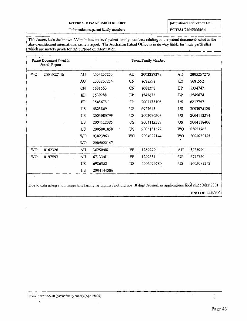
This Annex lists the known "A" publication level patent family members relating to the patent documents cited in the above-mentioned international search report. The Australian Patent Office is in no way liable for these particulars
which are merely ~iven for the purpose of information.
Patent Document Cited ia Patent Family Member Search Report
WO 2004022146 AU" 2003257270 AU 2003257271 A~U 2003257273
AU 2003257274 CN 1681551 CN 1681552
CN 1681553 CN 1688358 EP 1334742
EP 1539288 EP 1545673 EP 1545674
EP 1545675 ’ 310 2003175106 US 6812762
US 6823869 US 6927613 US 2003075180
US 2003080799 US 2003090308 US 2004112384
US 2004112385 US 2004112387 US 2004118406
US 2005081858 US 2005151572 WO 03023962
WO 03023963 WO 2004022144 WO 2004022145
WO 2004022147
WO 0162326 AU 34250/00 EP 1259279 AU 3425000
WO 0197893 AU 67133/01 EP 1292351 US 6772760
US 6986352 US 2002029780 US 2003089372
US 2004144386
Due to data inte~atian issues this family listing may not inelude I 0 digit Australian applications filed since May 2001.
END OF ANNEX
Form PCT!ISA]210 (patent family annex) (April 2005)
Page 43