workshops
TRANSCRIPT

Workshop Supplement
DesignModeler
Release: 12.0
1st Edition ANSYS, Inc.
is a UL registered ISO 9001:2000
Company
Inventory #002597
April 28, 2009

Table of Contents
TOC-1ANSYS, Inc. Proprietary© 2009 ANSYS, Inc. All rights reserved.
April 28, 2009Inventory #002597
DesignModeler

Workshop Supplement
DesignModeler
Table of ContentsInventory Number: 002597
1st EditionANSYS Release: 12.0
Published Date: April 28, 2009
Registered Trademarks:ANSYS® is a registered trademark of SAS IP Inc. All other product names mentioned in this manual are trademarks or registered trademarks of their respective manufacturers.
TOC-2ANSYS, Inc. Proprietary© 2009 ANSYS, Inc. All rights reserved.
April 28, 2009Inventory #002597
Disclaimer Notice:This document has been reviewed and approved in accordance with the ANSYS, Inc. Documentation Review and Approval Procedures.“This ANSYS Inc. software product (the Program) and program documentation (Documentation) are furnished by ANSYS, Inc. under an ANSYS Software License Agreement that contains provisions concerning non-disclosure, copying, length and nature of use, warranties, disclaimers and remedies, and other provisions. The Program and Documentation may be used or copied only in accordance with theterms of that License Agreement.”
Copyright © 2009 SAS IP, Inc.Proprietary data. Unauthorized use, distribution, o r duplication is prohibited.
All Rights Reserved.

Workshop Supplement
DesignModeler
Table of Contents
Workshop 2.1: GUI NavigationWorkshop 3.1: SketchingWorkshop 3.2: 3D GeometryWorkshop 3.3: Static MixerWorkshop 4.1: Catalytic ConverterWorkshop 5.1: 3D Curve Workshop 5.2: Pattern Operation
TOC-3ANSYS, Inc. Proprietary© 2009 ANSYS, Inc. All rights reserved.
April 28, 2009Inventory #002597
Workshop 5.2: Pattern OperationWorkshop 5.3: Enclosure OperationWorkshop 5.4: Mid Surface CreationWorkshop 6.1: Fill and Face DeleteWorkshop 6.2: Enclosure and SliceWorkshop 6.3: CAD RepairWorkshop 7.1: Pulley Model with ParametersWorkshop 8.1: Lines and Surface Bodies

Workshop 2.1
GUI Navigation
WS2.1-1ANSYS, Inc. Proprietary© 2009 ANSYS, Inc. All rights reserved.
April 28, 2009Inventory #002597
GUI Navigation
DesignModeler
WS2.1: GUI Navigation
Workshop SupplementGoals
• Goals: – Start DesignModeler and open an existing database (agdb).– Navigate through the GUI viewing controls.– Create a new plane on an existing face of the model.– Draw and dimension a 2-D sketch on the new plane
(dimensioning will adequately specify the size and location of the sketch)
WS2.1-2ANSYS, Inc. Proprietary© 2009 ANSYS, Inc. All rights reserved.
April 28, 2009Inventory #002597
of the sketch)– Extrude the sketch to modify the existing geometry (cut a
hole through the original part).– Save the project and exit

WS2.1: GUI Navigation
Workshop Supplement
• Start Workbench. Double click on Geometry under component systems.
• This will create a ‘Geometry component’ in the Project Schematic area.
Starting Workbench
WS2.1-3ANSYS, Inc. Proprietary© 2009 ANSYS, Inc. All rights reserved.
April 28, 2009Inventory #002597

WS2.1: GUI Navigation
Workshop Supplement
• Right click on and select “Import Geometry >Browse”, andselect link1.agdb from the list
• Double click on and DesignModeler will be launched
Launching DM
WS2.1-4ANSYS, Inc. Proprietary© 2009 ANSYS, Inc. All rights reserved.
April 28, 2009Inventory #002597

WS2.1: GUI Navigation
Workshop SupplementGenerate
When a DM database is first opened you must “Generate” it before you can work with it.
This is indicated by
WS2.1-5ANSYS, Inc. Proprietary© 2009 ANSYS, Inc. All rights reserved.
April 28, 2009Inventory #002597
This is indicated by the “lightening bolt” icon next to all branches in the tree outline.

WS2.1: GUI Navigation
Workshop SupplementModeling and Sketching Modes
• Click the “+” next to “XYPlane” in the tree then highlight “SKETCH1”.
– [Modeling]: Link1 > XYPlane > SKETCH1– Observe that the base sketch is now displayed in
yellow.– Click on the Sketching tab and observe that the
dimensions are now displayed.– Click on the Modeling tab.
WS2.1-6ANSYS, Inc. Proprietary© 2009 ANSYS, Inc. All rights reserved.
April 28, 2009Inventory #002597

WS2.1: GUI Navigation
Workshop SupplementTree Outline
• Click the “+” next to “Extrude1” to expand the branch (if you have not done so yet).
– [Modeling]: Extrude1 > SKETCH1– Observe that “SKETCH1” is associated with the
XYPlane as well as Extrude1 in the tree outline
WS2.1-7ANSYS, Inc. Proprietary© 2009 ANSYS, Inc. All rights reserved.
April 28, 2009Inventory #002597
SKETCH1

WS2.1: GUI Navigation
Workshop Supplement
Click the blue “Iso” ball in the triad in the graphics window.
Mouse and Manipulation of Views
RMB
WS2.1-8ANSYS, Inc. Proprietary© 2009 ANSYS, Inc. All rights reserved.
April 28, 2009Inventory #002597
This orients the model to an isometric view.Use the right mouse button and drag a zoom window around the top surface of the model. Note this is a shortcut for zoom operations (practice the use of mouse for graphics manipulation till you are familiar with the operations)
RMB

WS2.1: GUI Navigation
Workshop Supplement
Using the left mouse button click on the top surface to select it.• Click on the “new plane” icon to
create a plane. A preview of the plane is displayed with a triad at the plane origin (RGB = XYZ).
• Click on “Generate”.
Note: by pre-selecting the surface
Generate a New Plane
WS2.1-9ANSYS, Inc. Proprietary© 2009 ANSYS, Inc. All rights reserved.
April 28, 2009Inventory #002597
Note: by pre-selecting the surface then creating the plane the details indicate the plane will be a “From Face” type.
Leave the default settings in the plane details and “Generate” the plane.

WS2.1: GUI Navigation
Workshop SupplementDraw 2-D Sketches on the Active Plane
• Notice that “Plane4” is created and becomes the active plane.• Click on the “Look At” icon to orient Plane4 to a normal view.Go to the “Sketching” tab and draw a circle near the center of the plane.[Sketching] > Draw > Circle• The exact dimension (size and location of the circle) is given next
Look at
WS2.1-10ANSYS, Inc. Proprietary© 2009 ANSYS, Inc. All rights reserved.
April 28, 2009Inventory #002597
location of the circle) is given next

WS2.1: GUI Navigation
Workshop SupplementSelect and Details ViewBefore dimensioning the sketch we’ll verify some of the sizes of the original part.• Click the “Select” icon and
highlight the right edge of the sketch plane, length=10 mm.
• Repeat the above to verify the length of a horizontal edge is 80mm.
WS2.1-11ANSYS, Inc. Proprietary© 2009 ANSYS, Inc. All rights reserved.
April 28, 2009Inventory #002597
• Go to the dimensions toolbox and leave General as the default choice.
[Sketching] > Dimensions > General

WS2.1: GUI Navigation
Workshop SupplementDimensioning
“General” dimensioning is controlled via a RMB on the graphics screen.• To place the first dimension,
click RMB and choose “Horizontal”. Pick the circle center and the left edge of the sketch plane. Then place the dimension (H1) by clicking on a location.
WS2.1-12ANSYS, Inc. Proprietary© 2009 ANSYS, Inc. All rights reserved.
April 28, 2009Inventory #002597
location.
Note the “From Face” plane allows us to use the bounds of the plane for dimensioning.
• Repeat the above steps to place a vertical dimension from the circle center to one of the horizontal bounds of the plane.
• Finally dimension the circle.

WS2.1: GUI Navigation
Workshop SupplementEditing Dimensions
After the dimensions have been placed use the Details View to modify the 3 values manually
Use the following values to set dimensions of the sketch:
Horizontal = 40mm
WS2.1-13ANSYS, Inc. Proprietary© 2009 ANSYS, Inc. All rights reserved.
April 28, 2009Inventory #002597
Horizontal = 40mmVertical = 5mmDiameter = 5mm
Note: the dimension names in your sketch may vary from those shown here (you can change the name by using “Edit” under Dimensions)

WS2.1: GUI Navigation
Workshop SupplementExtrude a 2-D Sketch to Form a 3-D Feature
With the sketch fully defined we’ll create an extrusion to place a hole in the geometry.Pick the “Extrude” icon from the main menu.Setup the extrude operation via the details window as follows, then click “Generate” to extrude
WS2.1-14ANSYS, Inc. Proprietary© 2009 ANSYS, Inc. All rights reserved.
April 28, 2009Inventory #002597
Note: We changed the operation to “Cut Material” to create a hole. Since the operation must take place into the plane (-Z direction), the detail automatically changed to a “Reversed” direction. “Through All” is specified to cause the extrusion to pass through the entire body.

WS2.1: GUI Navigation
Workshop SupplementChanging Names in the Tree Outline
Click the “+” next to Plane4 in the tree and highlight Sketch2.
[Modeling] > Plane4 > Sketch2
In the Detail for Sketch2 change the Sketch name “Hole Sketch”.Highlight “Extrude2” in the tree.
[Modeling] > Extrude2In the Detail for Extrude2
WS2.1-15ANSYS, Inc. Proprietary© 2009 ANSYS, Inc. All rights reserved.
April 28, 2009Inventory #002597
In the Detail for Extrude2 change the Extrude name to “Center Hole”.
Note: spaces in names are removed:Hole Sketch => HoleSketch
Use an underscore “_” as a spacer if desired:Hole_Sketch => Hole_Sketch

WS2.1: GUI Navigation
Workshop SupplementSave as a Workbench Project and Close DM
Use the middle mouse button to rotate the model and inspect the feature. Note this is a shortcut for model rotations.Use the “View” menu toggle between the shaded and wireframe display modes.
Use “File > Save Project” to save the geometry and
WS2.1-16ANSYS, Inc. Proprietary© 2009 ANSYS, Inc. All rights reserved.
April 28, 2009Inventory #002597
the geometry and “File>Close DesignModeler” to exit

Workshop 3.1
Sketching
WS3.1-1ANSYS, Inc. Proprietary© 2009 ANSYS, Inc. All rights reserved.
April 28, 2009Inventory #002597
DesignModeler

WS3.1: Sketching
Workshop Supplement
• Using a simple example, let’s see how we put to use what we’ve seen so far (note RMB = Right Mouse Button).
• Goal:– Sketch a rectangle 50mm high and 75mm wide with the bottom left corner
at the origin.– Add a 10mm radius circle within the rectangle with the center 20mm from
the left side and 30mm from the bottom.– Place all dimensions where they can be easily viewed.
Goals
WS3.1-2ANSYS, Inc. Proprietary© 2009 ANSYS, Inc. All rights reserved.
April 28, 2009Inventory #002597
– Place all dimensions where they can be easily viewed.
R = 10mm
50mm
75mm
30mm
20mm

WS3.1: Sketching
Workshop Supplement
• Start Workbench. Double click on Geometry under component systems.
• This will create a ‘Geometry component’ in the Project Schematic area.
Launch DesignModeler
WS3.1-3ANSYS, Inc. Proprietary© 2009 ANSYS, Inc. All rights reserved.
April 28, 2009Inventory #002597

WS3.1: Sketching
Workshop Supplement
• Right click on and click on “New Geometry…”• This will launch a DM Window with a prompt to select
desired length unit. Select “Millimeter” and click OK.
Launch DesignModeler…
WS3.1-4ANSYS, Inc. Proprietary© 2009 ANSYS, Inc. All rights reserved.
April 28, 2009Inventory #002597

WS3.1: Sketching
Workshop Supplement
• When DM starts, switch to sketch mode using the Sketching tab.
– Note: use the “Look At” icon (or RMB options) to orient the sketch plane in the normal direction.
• Select the “Rectangle” tool and place the cursor at the origin.
– Once the “P” (point constraint) symbol shows, click, hold and drag, then release to create the rectangle.
Icon
RMB
Create Geometry
WS3.1-5ANSYS, Inc. Proprietary© 2009 ANSYS, Inc. All rights reserved.
April 28, 2009Inventory #002597
and drag, then release to create the rectangle.
Click
Hold
Release

WS3.1: Sketching
Workshop Supplement
• Before continuing, click the “Zoom to Fit” icon (or RMB menu).
• Now choose the “Circle” tool and click at an approximate location within the rectangle where the center would be, drag and release to create the circle.
Icon
RMB
Create Geometry…
WS3.1-6ANSYS, Inc. Proprietary© 2009 ANSYS, Inc. All rights reserved.
April 28, 2009Inventory #002597
Click, Hold
Release

WS3.1: Sketching
Workshop Supplement
• We’ll now formalize the sketch by adding dimensions.• Width of Rectangle: Select the Dimension toolbox and leave the default selection
at “General”.– Click on the top line of the rectangle to display the horizontal dimension ‘H1’.– Move the mouse upwards to move the dimension above the rectangle.– Click again to place the dimension.
Create Geometry…
WS3.1-7ANSYS, Inc. Proprietary© 2009 ANSYS, Inc. All rights reserved.
April 28, 2009Inventory #002597
Click
Mo
ve
Click

WS3.1: Sketching
Workshop Supplement
• Height of Rectangle: With the “General” selection– Click on the right line of the rectangle to display the height dimension.– Move the mouse to select a location for the dimension.– Click to place the dimension.
• Diameter of Circle: With the “General” selection – Click on the circle to display the diameter dimension.– Move the mouse to select a location for the dimension.
Create Geometry…
WS3.1-8ANSYS, Inc. Proprietary© 2009 ANSYS, Inc. All rights reserved.
April 28, 2009Inventory #002597
– Click to place the dimension.
• Horizontal Distance of Center of Circle: With the “General” selection – Click on the center of circle then click on left vertical edge of the rectangle.– Move the mouse to select a location for the horizontal distance dimension.– Click to place the dimension.
• Vertical Distance of Center of Circle: With the “General” selection – Click on the center of circle then click on bottom horizontal edge of the rectangle.– Move the mouse to select a location for the vertical distance dimension.– Click to place the dimension.

WS3.1: Sketching
Workshop Supplement
• Next modify the details for each dimension to the desired values as shown.
75mm
Create Geometry…
WS3.1-9ANSYS, Inc. Proprietary© 2009 ANSYS, Inc. All rights reserved.
April 28, 2009Inventory #002597
50mm
D = 20mm
30mm
20mm

WS3.1: Sketching
Workshop Supplement
• Use the “Move” function in the Dimension toolbox to position the dimensions– Select Move in the Dimensions toolbox.– Click on the dimension to be moved.– Move the mouse to select a position for the dimension.– Click to place the dimension.
Create Geometry…
WS3.1-10ANSYS, Inc. Proprietary© 2009 ANSYS, Inc. All rights reserved.
April 28, 2009Inventory #002597

WS3.1: Sketching
Workshop Supplement
• Now try animating several dimensions:– Choose the “Animate” function then click on a dimension in the graphics window
Create Geometry…
WS3.1-11ANSYS, Inc. Proprietary© 2009 ANSYS, Inc. All rights reserved.
April 28, 2009Inventory #002597
• Change the dimension display from “Name” to “Value”.

WS3.1: Sketching
Workshop Supplement
• As a last check of our stated goals go to the details for sketch 1 and change “Show Constraints?” to “Yes”.
Create Geometry…
WS3.1-12ANSYS, Inc. Proprietary© 2009 ANSYS, Inc. All rights reserved.
April 28, 2009Inventory #002597
• Scroll down to the details for Line7 and note the base point is coincident with the origin - - DM captured our design intent during sketching.
Note: leave DM session running as we will continue with this geometry later.

Workshop 3.2
3D Geometry
WS3.2-1ANSYS, Inc. Proprietary© 2009 ANSYS, Inc. All rights reserved.
April 28, 2009Inventory #002597
3D Geometry
DesignModeler

WS3.2: 3D Geometry
Workshop Supplement
• Goals:– Utilize the model created in Workshop 3-1 and generate 3D
geometry from the sketch.– Create a new sketch and extrude it to create a boss on the
original model. – Create another sketch and Imprint a face on the boss to allow for
applying boundary conditions to an FE model.– Save the model and Exit.
Goals
WS3.2-2ANSYS, Inc. Proprietary© 2009 ANSYS, Inc. All rights reserved.
April 28, 2009Inventory #002597
– Save the model and Exit.
• Continue with the database created in Workshop 3-1, if open. If saved and closed then open the saved project file.

WS3.2: 3D Geometry
Workshop Supplement
1) Make sure the Modeling tab is active (if not, then click to activate). The “Tree Outline” should be visible in the top left pane.
2) Note that “XYPlane” and “Sketch1” are active.
3) Click on “Extrude” icon from the toolbar.
1
5
2
3
Create Geometry
WS3.2-3ANSYS, Inc. Proprietary© 2009 ANSYS, Inc. All rights reserved.
April 28, 2009Inventory #002597
4) In the details view pane change the “Depth” for Extrude1 to 10 mm.
5) Click on “Generate” to generate the extrusion.
Note: You can rotate the view to get a better look at the extrusion before clicking generate.
1
4

WS3.2: 3D Geometry
Workshop Supplement
6) Ensure that the XYPlane is active and click on the “New Plane” icon.
7) In the Details of Plane4 set Transform 1 to be “Offset Z” and change the offset “Value” to 50mm.
8) “Generate” the Plane.
8
6
Create Geometry…
WS3.2-4ANSYS, Inc. Proprietary© 2009 ANSYS, Inc. All rights reserved.
April 28, 2009Inventory #002597
7

WS3.2: 3D Geometry
Workshop Supplement
9) Click the “Look At” icon to reorient the view.
10) Switch to Sketching mode and choose “Rectangle” from the drawing toolbox (check Auto-Fillet box).
11) Draw a rectangle and utilize Auto-Fillet approximately as shown here.
9
10
11
Create Geometry…
WS3.2-5ANSYS, Inc. Proprietary© 2009 ANSYS, Inc. All rights reserved.
April 28, 2009Inventory #002597
12) Click on the “Dimensions” toolbox. 12

WS3.2: 3D Geometry
Workshop Supplement
13) Dimension the sketch as shown below. Note: your dimension names may not match those shown.
13
Create Geometry…
WS3.2-6ANSYS, Inc. Proprietary© 2009 ANSYS, Inc. All rights reserved.
April 28, 2009Inventory #002597

WS3.2: 3D Geometry
Workshop Supplement
14) From the toolbar choose “Extrude” (do not generate yet!). An isometric view shows the proposed (wireframe) extrude using a surface-normal direction (facing away from the original model).
15) From the Detail window change the direction field from Normal to “Reversed”.
17
14
Create Geometry…
WS3.2-7ANSYS, Inc. Proprietary© 2009 ANSYS, Inc. All rights reserved.
April 28, 2009Inventory #002597
Normal to “Reversed”.16) Change the Type to “To Next”.17) “Generate” the extrusion.
16
15

WS3.2: 3D Geometry
Workshop Supplement
The extrude operation creates the boss which is merged with the original geometry.
Create Geometry…
WS3.2-8ANSYS, Inc. Proprietary© 2009 ANSYS, Inc. All rights reserved.
April 28, 2009Inventory #002597
Click on >Display Planebutton to turn off plane
+ dimensionsif necessary

WS3.2: 3D Geometry
Workshop Supplement
In our FE simulation we wish to add a boundary condition at an
arbitrary location on the boss. We will imprint a face on the boss for
that purpose.
18) Select (Highlight) the top surface of the boss.
19) Click the “New Plane” icon in
1920
Create Geometry…
WS3.2-9ANSYS, Inc. Proprietary© 2009 ANSYS, Inc. All rights reserved.
April 28, 2009Inventory #002597
19) Click the “New Plane” icon in the toolbar.
20) “Generate” the plane.18

WS3.2: 3D Geometry
Workshop Supplement
21) Click the “Look At” icon from the toolbar.
22) Go to sketch mode and choose circle from the draw toolbox.
23) Draw a circle approximately like the one shown here.
21
Create Geometry…
WS3.2-10ANSYS, Inc. Proprietary© 2009 ANSYS, Inc. All rights reserved.
April 28, 2009Inventory #002597
2223

WS3.2: 3D Geometry
Workshop Supplement
24) Add dimensions as shown at right. Note your dimension names may not match those shown here.
24
Create Geometry…
WS3.2-11ANSYS, Inc. Proprietary© 2009 ANSYS, Inc. All rights reserved.
April 28, 2009Inventory #002597

WS3.2: 3D Geometry
Workshop Supplement
25) Choose “Extrude” from the toolbar (do not Generate).
26) In the details change the operation to “Imprint Faces”.
27) “Generate” the extrusion
2527
Create Geometry…
WS3.2-12ANSYS, Inc. Proprietary© 2009 ANSYS, Inc. All rights reserved.
April 28, 2009Inventory #002597
26

WS3.2: 3D Geometry
Workshop Supplement
Make sure the surface selection filter is active and highlight (select)
the circular surface on the boss.(Rotate the Model as Desired)
Notice we now have a circular area that we can use for localized
Create Geometry…
WS3.2-13ANSYS, Inc. Proprietary© 2009 ANSYS, Inc. All rights reserved.
April 28, 2009Inventory #002597
area that we can use for localized boundary conditions in our
simulation.
Exit DM: “File>Close DesignModeler”

Workshop 3.3
Static Mixer
WS3.3-1ANSYS, Inc. Proprietary© 2009 ANSYS, Inc. All rights reserved.
April 28, 2009Inventory #002597
Static Mixer
DesignModeler

WS3.3: Static Mixer
Workshop Supplement
• This workshop will take you through the process of creating a geometry in DesignModeler and using the Automatic meshing method to create a simple mesh for that geometry.
• The basic steps involved in creating a CFD mesh are:
– 1. Create the Geometry (DesignModeler).
– 2. Define Named Selections for some 2D regions (DesignModeler).
Goals
WS3.3-2ANSYS, Inc. Proprietary© 2009 ANSYS, Inc. All rights reserved.
April 28, 2009Inventory #002597
– 2. Define Named Selections for some 2D regions (DesignModeler).
– 3. Create surface and volume mesh (Meshing).
• This workshop is intended to give you a feel for the geometry and mesh creation process from start to finish. Some of the methodsused and the steps you follow will be discussed and explainedin later lectures.

WS3.3: Static Mixer
Workshop Supplement
• The geometry you will be creating and meshing is shown below:
Goals…
WS3.3-3ANSYS, Inc. Proprietary© 2009 ANSYS, Inc. All rights reserved.
April 28, 2009Inventory #002597

WS3.3: Static Mixer
Workshop Supplement
2. Launch DesignModeler and start new geometry
• Double Click “Mesh” under “Component Systems”
1. Launch ANSYS Workbench
• Start > Programs > ANSYS 12.0 > ANSYS Workbench
Launch DesignModeler
WS3.3-4ANSYS, Inc. Proprietary© 2009 ANSYS, Inc. All rights reserved.
April 28, 2009Inventory #002597
“Component Systems”
• Right click on the Geometry box in the Project Schematic and click on “New Geometry…”
• Select Meter for length unit, then click OK

WS3.3: Static Mixer
Workshop Supplement
5. Modeling: Sketching tab
– Selecting the Sketching tab after selecting a plane creates a new sketch and toggles to Sketching mode
You will begin by creating a sketch of the main body profile which you will revolve about the Y-axis to create the main body of the mixer
3. Modeling: > ZXPlane
– Selecting ZXPlane on the tree displays the sketch plane on the Model View.
4. Click on the Look-At icon to orient the view normal to the plane.
Create Geometry
WS3.3-5ANSYS, Inc. Proprietary© 2009 ANSYS, Inc. All rights reserved.
April 28, 2009Inventory #002597
6. Sketching: Settings > Grid
– This is a simple geometry characterized by dimensions of 2.0 m, 1.0 m, & 0.5 m. A grid can be displayed and snapped to simplify the assignment of the proper dimensions.
7. Toggle on Show in 2D and Snap to Grid
8. Click on Major Grid Spacing and set it to 1.0 m
9. Click on Minor-Steps per Major and set it to 2
10. Zoom in on the model view (click and drag with the right mouse button) so that the area displayed is centered about the origin with six major steps in the x- and z-directions.

WS3.3: Static Mixer
Workshop Supplement
11. Sketching: > Draw > Polyline
– Left-click on the sketch to define each end point of the
You will now draw the outline of the main body profile as a closed-ended polyline. The profile of the polyline is shown below. Its left edge lies on the X-axis. The main portion is a square with a height and width of two. A tapered section reduces the width to 0.5 over a vertical distance of 1.0. The 0.5 width is maintained for a vertical distance of 1.0 and then the profile is closed as shown.
Create Geometry…
WS3.3-6ANSYS, Inc. Proprietary© 2009 ANSYS, Inc. All rights reserved.
April 28, 2009Inventory #002597
various line segments in turn. When you arrive back at the starting point, right click and select Closed Endfrom the menu that pops up.
You have now completed Sketch1. You will now revolve this sketch by 360 degrees about the X-axis to create the main body of the mixer.

WS3.3: Static Mixer
Workshop Supplement
12. Click on the Revolve icon on the menu bar to bring up the Details View for the revolve 3D operation
• The view will switch to the Modeling view
13. In the Details View, the Axis box should have Apply and Cancel tabs. If these
You will revolve Sketch1 by 360 degrees about the X-axis to create the main body of the mixer.
Create Geometry…
WS3.3-7ANSYS, Inc. Proprietary© 2009 ANSYS, Inc. All rights reserved.
April 28, 2009Inventory #002597
have Apply and Cancel tabs. If these are shown, left- click on the local Y-axis (which is aligned with global X-axis) and then left-click on Apply. If the Axis box, shows Not Selected, you must left-click in it first to bring up the Apply/Canceltabs.
14. Set the Angle to 360 degrees and leave the other settings at their default values

WS3.3: Static Mixer
Workshop Supplement
15. Click on Generate on the main toolbar
• You should see the solid geometry created by revolving Sketch1 through a full circle
about the X-axis
Create Geometry…
WS3.3-8ANSYS, Inc. Proprietary© 2009 ANSYS, Inc. All rights reserved.
April 28, 2009Inventory #002597

WS3.3: Static Mixer
Workshop Supplement
You will now create a new sketch on the Z-X plane to draw the profile of the first-side pipe. The body you’ve already created may make it difficult to see the sketch clearly, so you will begin by hiding this body.
16. In the Tree View, left-click on the + sign next to the last entry which shows 1 Part, 1 Body to expand it
17. Right click on Solid and select Hide BodySketch 2
Create Geometry…
WS3.3-9ANSYS, Inc. Proprietary© 2009 ANSYS, Inc. All rights reserved.
April 28, 2009Inventory #002597
• The body should disappear from the Model View
18. In the Tree View, left-click on the ZXPlane and then click on the New Sketch icon to create Sketch2
19. Sketching: > Draw > Circle
20. Click on the Look-At icon to orient the view normal to the ZXPlane
21. Draw a circle centered at (X=1,Z=1) with a radius of 0.5 m. You can snap to the grid by left-clicking with the mouse.
This completes Sketch2.
Sketch 2

WS3.3: Static Mixer
Workshop Supplement
You will extrude Sketch2 by 3 m in the direction normal to the ZXPlane to create the first side pipe.
22. Click on the Extrude icon on the menu bar to bring up the Details View for the extrude 3D operation.
• The view will switch to the Modeling View
• In the Details view, you can see that Sketch2 is already selected as the sketch for the extrude operation. By default, if
Create Geometry…
WS3.3-10ANSYS, Inc. Proprietary© 2009 ANSYS, Inc. All rights reserved.
April 28, 2009Inventory #002597
selected as the sketch for the extrude operation. By default, if you click on a 3D operation icon from an active sketch, that sketch will be selected. This selection can always be edited before or after you click Generate.
23. Change the Depth in the Details View to 3 m
24. Set the Type to Fixed and the Direction to Normal
• This will extrude Sketch2 3.0 m in the normal direction to theZXPlane (this is in the Y direction as you can see from the plane normal vector).
25. Leave all other settings at their default values and click Generate

WS3.3: Static Mixer
Workshop Supplement
26. Select the Solid from the Tree View
• The solid will appear as shown to the right
If you look at the Tree View, you will see that you still have 1 part and 1 body. When you add material to an existing model using a 3D operation such as revolve or extrude, DesignModeler will, by default, “melt” the solids together to create a single solid. You can control this by freezing individual solids or using the Add Frozen operation (discussed later).
Create Geometry…
WS3.3-11ANSYS, Inc. Proprietary© 2009 ANSYS, Inc. All rights reserved.
April 28, 2009Inventory #002597
• The solid will appear as shown to the right
27. Highlight the ZXPlane in the Tree View and click on the New Sketch icon.
Next you will draw the circle to define the second side pipe. Since the two otherwise identical side pipes are 180 degrees apart, Sketch3 will just be the mirror image of Sketch2 relative to the z=0 plane.

WS3.3: Static Mixer
Workshop Supplement
The circle for the second side pipe will also have a radius of 0.5 m, but will be centered at an (X,Z) location of (1,-1)
28. Sketching: > Draw > Circle
29. Click on the Look-At icon to orient the view normal to the ZXPlane.
30. Draw a circle centered at (X = 1, Z = -1) with a radius of 0.5 m. You can snap to the grid by left-clicking with the mouse. This
Sketch 3
Create Geometry…
WS3.3-12ANSYS, Inc. Proprietary© 2009 ANSYS, Inc. All rights reserved.
April 28, 2009Inventory #002597
You can snap to the grid by left-clicking with the mouse. This completes Sketch3.
31. Click on the Extrude icon. In the Details View, make sure that Sketch3 is selected and that the Depth is set to 3 m. Change the Direction to Reversed. This will extrude the sketch in the direction opposite to the plane normal (or in the -Y direction). Click Generate.
32. Right-click on Solid in the Tree View and unhide it (Show Body) to see the completed geometry.

WS3.3: Static Mixer
Workshop Supplement
Now we need to give specific names for some 2D regions so that later we can use them to create different boundaries.
33. Click Tools > Named Selection
34. In Details View window, set Named Selection to in1. Select the end surface of side pipe at the +Y location and click Apply in the Geometry selection in the Details View.
35. Click Generate
Create Geometry…
WS3.3-13ANSYS, Inc. Proprietary© 2009 ANSYS, Inc. All rights reserved.
April 28, 2009Inventory #002597
35. Click Generate

WS3.3: Static Mixer
Workshop Supplement
36. Repeat the previous three steps to create Named Selection in2 on the other side pipe end at –Y location and Named Selection out on the bottom pipe end at –X location
37. The geometry is now complete. Click on File>Save Project to save the project files.
in2
in1
Create Geometry…
WS3.3-14ANSYS, Inc. Proprietary© 2009 ANSYS, Inc. All rights reserved.
April 28, 2009Inventory #002597
File>Save Project to save the project files. Change the folder to your working directory, set the File name to StaticMixer.wbpj, and click Save.
You are now ready to proceed to Meshing.
out

WS3.3: Static Mixer
Workshop Supplement
38. Go to the main Workbench window
39. Right click on “Mesh” and click on “Edit…”
Launch Meshing
WS3.3-15ANSYS, Inc. Proprietary© 2009 ANSYS, Inc. All rights reserved.
April 28, 2009Inventory #002597

WS3.3: Static Mixer
Workshop Supplement
40. In the Details of “Mesh” panel, make sure that Physics Preference is set to CFD, and Relevance Center is set to Medium
41. Right-click Mesh in the Outline tree and select Generate Mesh
Workshop 3.3: Static Mixer
Create Mesh
WS3.3-16ANSYS, Inc. Proprietary© 2009 ANSYS, Inc. All rights reserved.
April 28, 2009Inventory #002597

WS3.3: Static Mixer
Workshop Supplement
• The final mesh is shown as following
42. Click File>Save Project… to save the project file
Create Mesh…
WS3.3-17ANSYS, Inc. Proprietary© 2009 ANSYS, Inc. All rights reserved.
April 28, 2009Inventory #002597

Workshop 4.1
Catalytic Converter
WS4.1-1ANSYS, Inc. Proprietary© 2009 ANSYS, Inc. All rights reserved.
April 28, 2009Inventory #002597
Catalytic Converter
DesignModeler

WS4.1: Catalytic Converter
Workshop SupplementGoals
• Goals:– Create the catalytic converter model shown below as 3 separate bodies – Create separate sketches and perform a skin/loft operation to make the
converter body
WS4.1-2ANSYS, Inc. Proprietary© 2009 ANSYS, Inc. All rights reserved.
April 28, 2009Inventory #002597

WS4.1: Catalytic Converter
Workshop Supplement
• Start Workbench. Double click on Geometry under Component Systems.
• This will create a ‘Geometry component’ in the Project Schematic area.
• Double click
to launch DM (use millimeter as the length
Starting Workbench
Double click
WS4.1-3ANSYS, Inc. Proprietary© 2009 ANSYS, Inc. All rights reserved.
April 28, 2009Inventory #002597
millimeter as the length unit)

WS4.1: Catalytic Converter
Workshop Supplement
1) Create the flange sketch #1– [Modeling] > A: Geometry > XYPlane
• Toolbar: New Sketch • Sketch1 will be created on XYPlane• In the Details view, rename Sketch1
to “BaseCircle”.• Toolbar: “Look At” icon
– [Sketching] > Draw > Circle• Move the cursor over the sketch
origin, then when the “P” is displayed
Step 1
WS4.1-4ANSYS, Inc. Proprietary© 2009 ANSYS, Inc. All rights reserved.
April 28, 2009Inventory #002597
origin, then when the “P” is displayed (auto-constraint), click on the left mouse button. Click again to define the radius.
– [Sketching] > Dimensions > Radius• Click on the circle to select it, then
click again on the screen to define where to place the dimension.
• In the Details view, define Dimensions > R1 as “2.5”.

WS4.1: Catalytic Converter
Workshop Supplement
Create the flange sketch #1 (cont’d)– [Sketching] > Modify > Split at Select
• Right click anywhere on the Modelview and select “Split Edge into n Equal Segments” from the pop-up menu.
• The Split tool will now change to Split Equal Segments. Enter “8” for the textbox n=.
• In the Model View, select the circle. It will now be split into eight
Step 1
WS4.1-5ANSYS, Inc. Proprietary© 2009 ANSYS, Inc. All rights reserved.
April 28, 2009Inventory #002597
It will now be split into eight segments.
Notes:We have now split the circle into 8 segments. We will create the profile of the flange by lofting four sketches using this one as our base. We will need to have the same number of divisions on each sketch, all with similar orientations. To simplify this, we will first reorient the circle by using a Move command.

WS4.1: Catalytic Converter
Workshop Supplement
Create the flange sketch #1 (cont’d)• On the Selection Toolbar, select the
“New Selection” icon . • Click on the “Select Mode” icon and
choose “Box Select”
• Left click and drag to draw a box, selecting the entire circle.
Step 1
WS4.1-6ANSYS, Inc. Proprietary© 2009 ANSYS, Inc. All rights reserved.
April 28, 2009Inventory #002597
selecting the entire circle.– [Sketching] > Modify > Move
• In the text boxes next to the Movetool, change r= to “22.5” and f= to “1”.
• Right-click on the Model View and select “Use Plane Origin as Handle”. This will make the moving reference point as the original, relative location of the sketch origin.

WS4.1: Catalytic Converter
Workshop Supplement
Create the flange sketch #1 (cont’d)• Right click anywhere on the Model
View and select “Rotate by r Degrees”. This makes the moving operation include a rotation, as specified by the value of “22.5” degrees entered earlier.
• Right click anywhere on the Model View and select “Paste at Plane Origin”. This completes the move operation by moving the model to the
Step 1
WS4.1-7ANSYS, Inc. Proprietary© 2009 ANSYS, Inc. All rights reserved.
April 28, 2009Inventory #002597
operation by moving the model to the origin. Since the reference point was the origin, this results in no translation but only a rotation, specified by r=22.5.
• Right click anywhere on the ModelView and select and left-clickEnd. This completes the Moveoperation.

WS4.1: Catalytic Converter
Workshop Supplement
Create the flange sketch #1 (cont’d)• You should see that the segments
have been rotated by 22.5 degrees. • Click on the “Select Mode” icon
and choose “Box Select”• Left click and drag to draw a box,
selecting the entire circle.– [Sketching] > Modify > Copy
• Click on the Copy tool to copy this profile.
Step 1
WS4.1-8ANSYS, Inc. Proprietary© 2009 ANSYS, Inc. All rights reserved.
April 28, 2009Inventory #002597
• Right-click anywhere on the Model View and select “Use Plane Origin as Paste Handle” to make the paste operation use the original, relative location of the sketch origin as the pasting point.

WS4.1: Catalytic Converter
Workshop Supplement
2) Create the flange sketch #2– [Modeling] > Toolbar: XYPlane– Toolbar: New Plane
• Select the New Plane icon from the Active Plane/Sketch Toolbar. This creates Plane4 based on XYPlane.
• In the Details view, set Transform 1 to Offset Z, change FD1, Value to be “1”.
– Toolbar: Generate– [Sketching] > Modify > Paste
Step 2
WS4.1-9ANSYS, Inc. Proprietary© 2009 ANSYS, Inc. All rights reserved.
April 28, 2009Inventory #002597
– [Sketching] > Modify > Paste• Enter “0” for r= and “1.05” for f=.• Right-click anywhere on the Model
View and select “Scale by factor f”. This will scale the original sketch profile by a factor of 1.05 for our new sketch.

WS4.1: Catalytic Converter
Workshop Supplement
Create the flange sketch #2 (cont’d)• Right-click on the Model View and select “Paste at
Plane Origin”. Our reference point was the sketch origin from BaseCircle, and the pasting location is the origin on Sketch2, so this essentially copies the original circle onto Sketch2 with a scale factor of f=1.05.
Step 2
WS4.1-10ANSYS, Inc. Proprietary© 2009 ANSYS, Inc. All rights reserved.
April 28, 2009Inventory #002597
• Right-click on the Model Viewand select and left-click on End. This terminates the Paste operation.

WS4.1: Catalytic Converter
Workshop Supplement
Create the flange sketch #2 (cont’d)– [Modeling] > A: Geometry > XYPlane >
BaseCircle• Right-click on BaseCircle and select
“Always Show Sketch”– [Modeling] > A: Geometry > Plane4 >
Sketch2• Right-click on Sketch2 and select
“Always Show Sketch”. This keeps both sketches visible so we can easily see that one circle is the same as the
Step 2
WS4.1-11ANSYS, Inc. Proprietary© 2009 ANSYS, Inc. All rights reserved.
April 28, 2009Inventory #002597
see that one circle is the same as the other except for the Z offset and the 1.05 scale factor.

WS4.1: Catalytic Converter
Workshop Supplement
3) Create the flange sketch #3– Toolbar: XYPlane– Toolbar: New Plane
• Select the New Plane icon from the Active Plane/Sketch Toolbar. This creates Plane5 based on XYPlane.
• In the Details view, set Transform 1 to Offset Z, change FD1, Value to “5”.
– Toolbar: Generate
Step 3
WS4.1-12ANSYS, Inc. Proprietary© 2009 ANSYS, Inc. All rights reserved.
April 28, 2009Inventory #002597
– [Sketching] > Draw > Rectangle• Check Auto-Fillet checkmark next
to the Rectangle tool.• Click once to define one corner of
the rectangle, click again to define its diagonal, and click a third time to define the fillet radius.

WS4.1: Catalytic Converter
Workshop Supplement
Create the flange sketch #3 (cont’d)– [Sketching] > Dimensions > General
• Dimension the sketch as shown at right.
• In the Details view, change Dimensions to be the values shown in the right plot
• On the toolbar click “New Selection” icon and set the mode to “Box Select”
Step 3
WS4.1-13ANSYS, Inc. Proprietary© 2009 ANSYS, Inc. All rights reserved.
April 28, 2009Inventory #002597
• Left click and drag to select the entire sketch.
– [Sketching] > Modify > Copy• Right-click anywhere on the Model
View and select “Use Plane Origin as Handle”.

WS4.1: Catalytic Converter
Workshop Supplement
4) Create the flange sketch #4– [Modeling] > A: Geometry > Plane6– Highlight XY Plane– Toolbar: New Plane
• Select the New Plane icon from the Active Plane/Sketch Toolbar. This creates Plane6 based on XYPlane.
• In the Details view, set Transform 1 to Offset Z, change FD1, Value to “6”.
– Toolbar: Generate– [Sketching] > Modify > Paste
Step 4
WS4.1-14ANSYS, Inc. Proprietary© 2009 ANSYS, Inc. All rights reserved.
April 28, 2009Inventory #002597
– [Sketching] > Modify > Paste• Enter “0” for r= and “1.05” for f=. Right-
click anywhere on the Model View and select “Scale by factor f”. (scales the original sketch profile by a factor of 1.05).
• Right-click on the Model View and select “Paste at Plane Origin”. Our reference point was the sketch origin from Plane5, and the pasting location is the origin on Plane6, so this copies the rectangle onto Plane6 and scales it by 1.05. Right-click on the Model Viewand select and left-click End.

WS4.1: Catalytic Converter
Workshop Supplement
Create the flange sketch #4 (cont’d)– [Modeling] > Unnamed > Plane5 >
Sketch3• Right-click on Sketch3 and select
“Always Show Sketch”– [Modeling] > Unnamed > Plane6 >
Sketch4• Right-click on Sketch4 and select
“Always Show Sketch”. This makes both sketches visible at the same time, so we can easily see that the
Step 4
WS4.1-15ANSYS, Inc. Proprietary© 2009 ANSYS, Inc. All rights reserved.
April 28, 2009Inventory #002597
time, so we can easily see that the original profile is indeed scaled by a factor of 1.05.

WS4.1: Catalytic Converter
Workshop Supplement
5) Create the flange – Toolbar: Skin/Loft
• Select the Skin/Loft icon• and the Details view, Profiles should
be active. • Hold the CTRL key and, from the
graphics window select the four sketches shown at the right in the direction noted by the solid arrow. They will highlight in yellow.
Step 5
WS4.1-16ANSYS, Inc. Proprietary© 2009 ANSYS, Inc. All rights reserved.
April 28, 2009Inventory #002597
• Note: it is only necessary to select one line from each sketch.
• Apply• A grey line appears showing the
lofting behavior. In this case, the lofting looks correct. If your grey line does not seem correct, i.e. it appears twisted, this can be resolved by right-clicking anywhere on the Model Viewand selecting “Fix Guide Line”.

WS4.1: Catalytic Converter
Workshop Supplement
Create the flange (cont’d)• Select the four vertices, which are
circled on the top-right image. This redefines the lofting guide such that the model will not ‘twist’.
• After this is done, the guiding profile, should be defined correctly.
Step 5
WS4.1-17ANSYS, Inc. Proprietary© 2009 ANSYS, Inc. All rights reserved.
April 28, 2009Inventory #002597

WS4.1: Catalytic Converter
Workshop Supplement
Create the flange section (cont’d)– Set the ‘Merge Topology’ option to ‘Yes’.– Toolbar: Generate
• The resulting solid (shown here in wire frame display) appears on the right.
Notes: Setting ‘Merge topology’ to yes optimizes the number faces for the skin/loft operation. This results in a smoother surface mesh.
Step 5
WS4.1-18ANSYS, Inc. Proprietary© 2009 ANSYS, Inc. All rights reserved.
April 28, 2009Inventory #002597

WS4.1: Catalytic Converter
Workshop Supplement
6) Create the pipe bend– [Modeling] > A: Geometry > XYPlane– Toolbar: New Sketch
• Sketch5 will be created on XYPlane• Choose the “Look At” icon• In the Details view, rename Sketch5
to “RevolveAxis”.– [Sketching] > Draw > Line
• Create a single line as shown on the bottom-right. Make sure it has an
Step 6
WS4.1-19ANSYS, Inc. Proprietary© 2009 ANSYS, Inc. All rights reserved.
April 28, 2009Inventory #002597
bottom-right. Make sure it has an auto-constraint of “V” (vertical).
– [Sketching] > Dimensions > General• Dimension the distance of the line
from the vertical axis Y as “15”.

WS4.1: Catalytic Converter
Workshop Supplement
Create the pipe bend (cont’d)– [Modeling] > A: Geometry > XYPlane >
BaseCircle– Toolbar: Revolve
• In the Details view, change Base Object to “BaseCircle”.
• Add “RevolveAxis” as the Axis.• Look at the Model View. The
revolution operation is in the wrong direction, so change Direction to
Step 6
WS4.1-20ANSYS, Inc. Proprietary© 2009 ANSYS, Inc. All rights reserved.
April 28, 2009Inventory #002597
“Reversed” with the pull-down menu.• Change FD1, Angle (>0) to “45”. The
revolve preview should look similar to the top-right image.
– Toolbar: Generate• This will generate the pipe bend.

WS4.1: Catalytic Converter
Workshop Supplement
7) Create New Plane at the pipe end• Left click the pipe end to highlight it, click New Plane icon, leave everything as default in
detailed window, click Generate.– Toolbar: Extrude
• In the Details view, change FD1, Depth (>0) to “10”– Toolbar: Generate
• The straight end of the pipe should be generated.
Step 7
WS4.1-21ANSYS, Inc. Proprietary© 2009 ANSYS, Inc. All rights reserved.
April 28, 2009Inventory #002597

WS4.1: Catalytic Converter
Workshop Supplement
• You have created one end of the catalytic converter. To create the other end, you can copy the solid part you have created to a new plane.
• The first step is to create the destination plane. Select Plane 6 from the tree view. You can see that it is located at the base of the solid part. Make sure that Plane 6 is selected as the Active Plane and click on the New Plane icon. Plane 8 will be located 20 mm from Plane 6 in the +z direction. You should also reverse the normal direction. Once you have entered the data, click on Generate to create Plane 8.
Step 7
WS4.1-22ANSYS, Inc. Proprietary© 2009 ANSYS, Inc. All rights reserved.
April 28, 2009Inventory #002597
the data, click on Generate to create Plane 8.• You will now copy the solid part you have created from
Plane 6 to Plane 8. Click on Create/Body Operation and change the type to ‘Move’. Select the Body and click Apply. Change Preserve bodies to ‘Yes’. Set the Source Plane to Plane 6 and the Destination Plane to Plane 8 and click Generate.

WS4.1: Catalytic Converter
Workshop Supplement
You will now complete the model by extruding the sketch on Plane 6 to the base face of the new end of the catalytic converter that you just created.Notes: This new solid will represent the porous region of
the converter. To be able to identify this internal mesh region and set flow resistances, this solid should NOT be merged with the rest of the geometry. To keep it separated it will be generated as a ‘Frozen Material’.
• Set the 3D operation to be Extrude.• Click in the Base Object List, highlight Sketch 4 in the
Step 7
WS4.1-23ANSYS, Inc. Proprietary© 2009 ANSYS, Inc. All rights reserved.
April 28, 2009Inventory #002597
• Click in the Base Object List, highlight Sketch 4 in the tree view (located as a sub-object of Plane 6). You should see the base profile of the first end section become highlighted. Click Apply.
• Set the Operation to ‘Add Frozen’ and the Type to ‘To Next’.
• Click on Generate to add the material. Note that the number of bodies and parts has now increased to three.

Workshop 5.1
3D Curve
WS5.1-1ANSYS, Inc. Proprietary© 2009 ANSYS, Inc. All rights reserved.
April 28, 2009Inventory #002597
3D Curve
DesignModeler

Workshop SupplementWorkshop 5.1: 3D Curve
•Goals:–Utilize a 3D Coordinate point file to generate
a 3D curve.–Use >Sweep to create a new part from the
curve.• Extrude, Revolve, etc, could similarly be used
WS5.1-2ANSYS, Inc. Proprietary© 2009 ANSYS, Inc. All rights reserved.
April 28, 2009Inventory #002597

Workshop SupplementWorkshop 5.1: 3D Curve
• Project Page> Component Systems> Geometry
WS5.1-3ANSYS, Inc. Proprietary© 2009 ANSYS, Inc. All rights reserved.
April 28, 2009Inventory #002597

Workshop SupplementWorkshop 5.1: 3D Curve
• Project Page> Component Systems> Geometry
a
b RMB
WS5.1-4ANSYS, Inc. Proprietary© 2009 ANSYS, Inc. All rights reserved.
April 28, 2009Inventory #002597
• DM will Open. When prompted choose “mm” as the length unit

Workshop SupplementWorkshop 5.1: 3D Curve
1. >Concept>3D Curve2. In Details,
• >Definition should be “From Coordinates File”
• At “>Coordinates File” click … to browse
3. Browse as necessary to file
1
WS5.1-5ANSYS, Inc. Proprietary© 2009 ANSYS, Inc. All rights reserved.
April 28, 2009Inventory #002597
3. Browse as necessary to file “sine_points.txt” and >Open it
“>Generate” the 3D Curve “Line Body”
2
3

Workshop Supplement
4. From the Tree, select the “Curve1” 3d Curve
Name the selection:5. >Tools>Named Selection6. In the Tree, select “Line Body” under “
Part, 1 Body”7. Click “Apply” in the Details window for
Workshop 5.1: 3D Curve
WS5.1-6ANSYS, Inc. Proprietary© 2009 ANSYS, Inc. All rights reserved.
April 28, 2009Inventory #002597
7. Click “Apply” in the Details window for Geometry
Click “>Generate”

Workshop Supplement
8. Select “NamedSel1” from the tree9. Click on “Revolve”10. Select the Y-axis11. Click “>Apply” in the Details window for
Axis
Workshop 5.1: 3D Curve
WS5.1-7ANSYS, Inc. Proprietary© 2009 ANSYS, Inc. All rights reserved.
April 28, 2009Inventory #002597
Click here to select the y-axis

Workshop Supplement
12. Select “FD1, Angle” in the Details window and enter a value of 360 to replace the default value.
13. “>Generate” the surface
Workshop 5.1: 3D Curve
WS5.1-8ANSYS, Inc. Proprietary© 2009 ANSYS, Inc. All rights reserved.
April 28, 2009Inventory #002597
Resulting3D SurfaceBody

Workshop 5.2
Pattern Operation
WS5.2-1ANSYS, Inc. Proprietary© 2009 ANSYS, Inc. All rights reserved.
April 28, 2009Inventory #002597
Pattern Operation
DesignModeler

Workshop SupplementWorkshop 5.2: Pattern Operation
• Goals:– Import a Model in Parasolid format–Add a hole and then use the Pattern Operation to up grade the part
to a Bolted Flange interface.
WS5.2-2ANSYS, Inc. Proprietary© 2009 ANSYS, Inc. All rights reserved.
April 28, 2009Inventory #002597

Workshop SupplementWorkshop 5.2: Pattern Operation
• Project Page> Component Systems> Geometry
WS5.2-3ANSYS, Inc. Proprietary© 2009 ANSYS, Inc. All rights reserved.
April 28, 2009Inventory #002597

Workshop SupplementWorkshop 5.2: Pattern Operation
• Project Page> Component Systems> Geometry
a
b RMB
WS5.2-4ANSYS, Inc. Proprietary© 2009 ANSYS, Inc. All rights reserved.
April 28, 2009Inventory #002597
• DM will Open. When prompted choose “mm” as the length unit

Workshop SupplementWorkshop 5.2: Pattern Operation
Import the Parasolids file “fan_hub.x_t”.
1. [Main menu] >File>Import External Geometry File . . . Browse to file “fan_hub.x_t” and open.
2. “Generate” the import. 1
WS5.2-5ANSYS, Inc. Proprietary© 2009 ANSYS, Inc. All rights reserved.
April 28, 2009Inventory #002597
2

Workshop SupplementWorkshop 5.2: Pattern Operation
3. Select the large Annular face4. Click the “New Plane” Toolbar5. “Generate” the new plane6. Switch to >Sketching mode7. Draw an 8 mm diameter circle on
the face and position the circle 17 mm from the vertical and horizontal axes. 3
4
5
6
WS5.2-6ANSYS, Inc. Proprietary© 2009 ANSYS, Inc. All rights reserved.
April 28, 2009Inventory #002597
6
7

Workshop SupplementWorkshop 5.2: Pattern Operation
8. Click the “Extrude” toolbar 9. Change Operation to “Cut Material”10. Change Type to “Through All”11. “>Generate” the (first) hole
The first hole is made, now get prepared to “>Pattern” (copy) it around.
Reorient the model and/or click on the Blue ISO Triad Ball as desired.
8
12
11
WS5.2-7ANSYS, Inc. Proprietary© 2009 ANSYS, Inc. All rights reserved.
April 28, 2009Inventory #002597
ISO Triad Ball as desired.
12. In the >Tree, click on ZXPlane to make it active - - a useful axis appears.
9
10

Workshop SupplementWorkshop 5.2: Pattern Operation
13. Use the select filter as necessary to select the hole’s cylindrical bore surface.
14. >Create> Pattern
From the Details menu:15. >Geometry>Apply
• The hole was already selected
16. Change the Pattern type to “Circular”17. Select the axis that goes thru the large hole
in the center of the part and click on >Apply 17
13
WS5.2-8ANSYS, Inc. Proprietary© 2009 ANSYS, Inc. All rights reserved.
April 28, 2009Inventory #002597
in the center of the part and click on >Apply (note, if you don’t see an appropriate axis, you may have to activate ZX or YZ Plane in the tree).
18. Change Copies to 5 (note you will get 6 holes total - - this includes the original plus 5 copies)
19. “>Generate” to create hole pattern
15-18
Final
14

Workshop 5.3
Enclosure Operation
WS5.3-1ANSYS, Inc. Proprietary© 2009 ANSYS, Inc. All rights reserved.
April 28, 2009Inventory #002597
Enclosure Operation
DesignModeler

Workshop Supplement
Workshop 5.3: Enclosure Operation
• Goals:– Import a model in Para-solid format–Use the enclosure operation to create a solid regio n
representing the model’s surrounding field
WS5.3-2ANSYS, Inc. Proprietary© 2009 ANSYS, Inc. All rights reserved.
April 28, 2009Inventory #002597

Workshop Supplement
Workshop 5.3: Enclosure Operation
• Project Page> Component Systems> Geometry
WS5.3-3ANSYS, Inc. Proprietary© 2009 ANSYS, Inc. All rights reserved.
April 28, 2009Inventory #002597

Workshop Supplement
Workshop 5.3: Enclosure Operation
• Project Page> Component Systems> Geometry
a
b RMB
WS5.3-4ANSYS, Inc. Proprietary© 2009 ANSYS, Inc. All rights reserved.
April 28, 2009Inventory #002597
• DM will Open. When prompted choose “meter” as the length unit

Workshop Supplement
Workshop 5.3: Enclosure Operation
Import the Parasolids file “blade.x_t”
1. [Main menu] >File> Import External Geometry File . . . Browse to file “blade.x_t” and open.
2. “Generate” the import.
WS5.3-5ANSYS, Inc. Proprietary© 2009 ANSYS, Inc. All rights reserved.
April 28, 2009Inventory #002597

Workshop Supplement
Workshop 5.3: Enclosure Operation
WS5.3-6ANSYS, Inc. Proprietary© 2009 ANSYS, Inc. All rights reserved.
April 28, 2009Inventory #002597

Workshop Supplement
Workshop 5.3: Enclosure Operation
3. From the “Tools” menu choose “Enclosure”
4. Choose “Cylinder” from the shape field in the details window
5. “Generate” the enclosure
WS5.3-7ANSYS, Inc. Proprietary© 2009 ANSYS, Inc. All rights reserved.
April 28, 2009Inventory #002597
Note: we left the cushion field set to the default 1m. Larger or smaller bounding enclosures can be defined using this field.

Workshop Supplement
Workshop 5.3: Enclosure Operation
• With the enclosure generated, notice there are now 2 bodies in the tree, one frozen (the enclosure) and one active (the blade)
WS5.3-8ANSYS, Inc. Proprietary© 2009 ANSYS, Inc. All rights reserved.
April 28, 2009Inventory #002597

Workshop Supplement
Workshop 5.3: Enclosure Operation
6. From the tree highlight the active solid (the blade), RMB and “Hide Body”
6
WS5.3-9ANSYS, Inc. Proprietary© 2009 ANSYS, Inc. All rights reserved.
April 28, 2009Inventory #002597
6
With the blade hidden it can be seen that the enclosure contains a void representing the boundaries of the structure. This enclosure is suitable for meshing .

Workshop 5.4
WS5.4-1ANSYS, Inc. Proprietary© 2009 ANSYS, Inc. All rights reserved.
April 28, 2009Inventory #002597
Mid Surface Creation
DesignModeler

Workshop SupplementWorkshop 5.4: Mid-Surface Creation - Overview
• Goal– Familiarize users with mid-surface
capabilities – Demonstrate manual and automatic
pair detection– Demonstrate surface extension for
interfaces
WS5.4-2ANSYS, Inc. Proprietary© 2009 ANSYS, Inc. All rights reserved.
April 28, 2009Inventory #002597
• Model Description– 2 part bracket with consistent cross
sections– Since the model has consistent
cross sections, shell elements will be used to mesh the model. This saves time and CPU resources.

Workshop SupplementWorkshop 5.4: Mid Surface Creation
• Project Page> Component Systems> Geometry
WS5.4-3ANSYS, Inc. Proprietary© 2009 ANSYS, Inc. All rights reserved.
April 28, 2009Inventory #002597

Workshop SupplementWorkshop 5.4: Mid Surface Creation
• Project Page> Component Systems> Geometry
a
b RMB
WS5.4-4ANSYS, Inc. Proprietary© 2009 ANSYS, Inc. All rights reserved.
April 28, 2009Inventory #002597
• DM will Open. When prompted choose “mm” as the length unit

Workshop SupplementWorkshop 5.4: Mid Surface Creation
Import the Parasolids file “bracket_mid_surface.x_t”
1. [Main menu] >File> Import External Geometry File . . . Browse to file “bracket_mid_surface.x_t” and open.
2. “Generate” the import.
WS5.4-5ANSYS, Inc. Proprietary© 2009 ANSYS, Inc. All rights reserved.
April 28, 2009Inventory #002597

Workshop Supplement
In the Model Tree, note that there are 2 separate parts:
Workshop 5.4: Mid-Surface Creation
WS5.4-6ANSYS, Inc. Proprietary© 2009 ANSYS, Inc. All rights reserved.
April 28, 2009Inventory #002597

Workshop SupplementWorkshop 5.4: Mid-Surface Creation
3. Each body of this model has different thicknesses. These thickness dimensions will be entered into the Maximum Threshold and Minimum Threshold fields in the Details of the MidSurf object.
Menu Bar > Selection Filter – Edges.
Use the status bar measuring tools to verify these thicknesses.
WS5.4-7ANSYS, Inc. Proprietary© 2009 ANSYS, Inc. All rights reserved.
April 28, 2009Inventory #002597
Smaller Body Thickness = 1mm Larger Body Thickness = 2mm

Workshop SupplementWorkshop 5.4: Mid-Surface Creation
4. Insert a mid-surface objectMain Menu > Tools > Mid-Surface
5. In the Details of MidSurf1, change the Selection Method to Automatic
WS5.4-8ANSYS, Inc. Proprietary© 2009 ANSYS, Inc. All rights reserved.
April 28, 2009Inventory #002597
6. Enter the Minimum Threshold of 1mm and Maximum Threshold of 2mm obtained from step 3.

Workshop SupplementWorkshop 5.4: Mid-Surface Creation
7. Set “Find Face Pairs Now?” to “Yes”
WS5.4-9ANSYS, Inc. Proprietary© 2009 ANSYS, Inc. All rights reserved.
April 28, 2009Inventory #002597
8. The Face Pair Automatic Selection method will select 11 face pairs. However, the automatic selection method has incorrectly identified the following features:a) A face pair that is not needed.
b) A face pair whereby the normal will need to be reversed

Workshop SupplementWorkshop 5.4: Mid-Surface Creation
9. Editing Face Pairs
– The face colors help to indicate the current mode when adding or removing face pairs from the selection set.
WS5.4-10ANSYS, Inc. Proprietary© 2009 ANSYS, Inc. All rights reserved.
April 28, 2009Inventory #002597

Workshop SupplementWorkshop 5.4: Mid-Surface Creation
10. To Remove Face Pairs, Click in the Details of MidSurf1 – Face Pairs to enter the selection mode (Apply / Cancel).
11. In the Graphics Window- Zoom as needed.- Click on the face to Remove.- Right click to display the Context
WS5.4-11ANSYS, Inc. Proprietary© 2009 ANSYS, Inc. All rights reserved.
April 28, 2009Inventory #002597
- Right click to display the Context menu.
- Select : Remove Face Pairs.
12. Note how the context bar indicates
“Select face pairs to remove”
Select this Face

Workshop SupplementWorkshop 5.4: Mid-Surface Creation
13. To Reverse Face Pairs, Click in the Details of MidSurf1 – Face Pairs to enter the selection mode (Apply / Cancel).
14. In the Graphics Window- Zoom as needed.- Click on the face to Reverse.- Right click to display the Context
menu.
WS5.4-12ANSYS, Inc. Proprietary© 2009 ANSYS, Inc. All rights reserved.
April 28, 2009Inventory #002597
menu.- Select : Reverse Face Pairs
15. Note how the context bar indicates “Select face pairs to reverse”
Note that the Reverse Face pair mode operates as a toggle.

Workshop SupplementWorkshop 5.4: Mid-Surface Creation
16. Generate the Mid-Surface
WS5.4-13ANSYS, Inc. Proprietary© 2009 ANSYS, Inc. All rights reserved.
April 28, 2009Inventory #002597

Workshop SupplementWorkshop 5.4: Mid-Surface Creation
17. Now, instead of two solid bodies, there are four surface bodies. They cannot be combined into a single body because the "T" intersections would cause it to be non-manifold. Also, in the final figure below, you will see that the resulting surface bodies for the back brace are automatically extended/trimmed to meet the main part of the bracket, as these were all part of one solid body originally. However, the front brace was a separate body, so it is not automatically extended.
WS5.4-14ANSYS, Inc. Proprietary© 2009 ANSYS, Inc. All rights reserved.
April 28, 2009Inventory #002597
Connected
Not Connected

Workshop SupplementWorkshop 5.4: Mid-Surface Creation
18. The Surface Extension feature can be used to extend the front brace edge so that it meets the main bracket surface.
Insert a Surface Extension object. Main Menu > Tools > Surface Extension
WS5.4-15ANSYS, Inc. Proprietary© 2009 ANSYS, Inc. All rights reserved.
April 28, 2009Inventory #002597
Note: It may be helpful to suppress the other bodies.

Workshop SupplementWorkshop 5.4: Mid-Surface Creation
19. Click in the Details of SurfaceExt1 – Edges to enter the selection mode and select both edges (Apply / Cancel). Select: Apply
WS5.4-16ANSYS, Inc. Proprietary© 2009 ANSYS, Inc. All rights reserved.
April 28, 2009Inventory #002597

Workshop SupplementWorkshop 5.4: Mid-Surface Creation
20. In the Details of SurfaceExt1 – Extent > Change the Extent to “To Next”.
21. Generate
– Surface edges are now extended.
WS5.4-17ANSYS, Inc. Proprietary© 2009 ANSYS, Inc. All rights reserved.
April 28, 2009Inventory #002597
Workshop SupplementWorkshop 5.4: Mid-Surface Creation
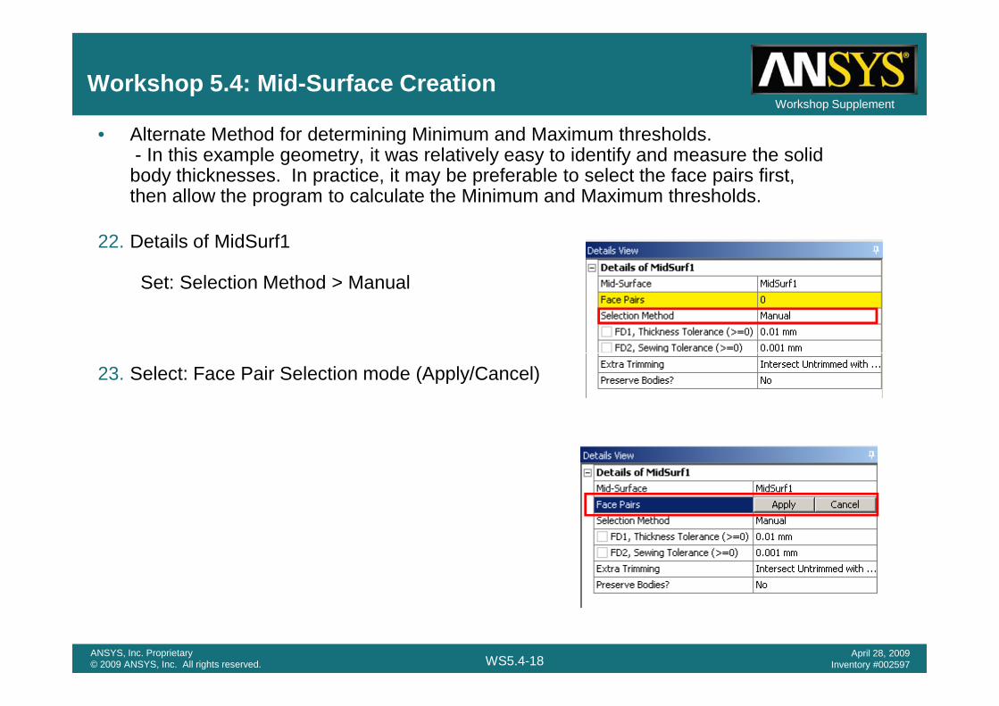
• Alternate Method for determining Minimum and Maximum thresholds. - In this example geometry, it was relatively easy to identify and measure the solid body thicknesses. In practice, it may be preferable to select the face pairs first, then allow the program to calculate the Minimum and Maximum thresholds.
22. Details of MidSurf1
Set: Selection Method > Manual
WS5.4-18ANSYS, Inc. Proprietary© 2009 ANSYS, Inc. All rights reserved.
April 28, 2009Inventory #002597
23. Select: Face Pair Selection mode (Apply/Cancel)

Workshop SupplementWorkshop 5.4: Mid-Surface Creation
24. Hold CTRL key down and select the face pairs on the large bracket to represent the 2mm thickness. Use the selection rectangles in the lower left corner to choose hidden faces).
25. Then, CTRL key and select the face pairs on the small bracket to represent the 1mm thickness.
• Select: Face Pairs : Apply
WS5.4-19ANSYS, Inc. Proprietary© 2009 ANSYS, Inc. All rights reserved.
April 28, 2009Inventory #002597
• Note that 2 Face Pairs are now in the selection set. 1 Pair representing 2mm, the other representing 1mm.

Workshop SupplementWorkshop 5.4: Mid-Surface Creation
26. Select: Selection Method : Automatic
• Note that Minimum Threshold and Maximum Threshold have been filled in automatically.
WS5.4-20ANSYS, Inc. Proprietary© 2009 ANSYS, Inc. All rights reserved.
April 28, 2009Inventory #002597
27. Find Face Pairs Now? > Yes – Add to Face Pairs

Workshop SupplementWorkshop 5.4: Mid-Surface Creation
28. The Face Pair Automatic Selection method has selected 11 face pairs which is the same number from Step 8.
WS5.4-21ANSYS, Inc. Proprietary© 2009 ANSYS, Inc. All rights reserved.
April 28, 2009Inventory #002597

Workshop 6.1
Fill and Face Delete
WS6.1-1ANSYS, Inc. Proprietary© 2009 ANSYS, Inc. All rights reserved.
April 28, 2009Inventory #002597
Fill and Face Delete
DesignModeler

Workshop Supplement
Workshop 6.1, Fill and Face Delete
• Project Page> Component Systems> Geometry
WS6.1-2ANSYS, Inc. Proprietary© 2009 ANSYS, Inc. All rights reserved.
April 28, 2009Inventory #002597

Workshop Supplement
Workshop 6.1, Fill and Face Delete
• Project Page> Component Systems> Geometry
a
b RMB
WS6.1-3ANSYS, Inc. Proprietary© 2009 ANSYS, Inc. All rights reserved.
April 28, 2009Inventory #002597
• DM will Open. When prompted choose “meter” as the length unit

Workshop Supplement
1. Import external geometry into DM
– Click File>Import External Geometry File and select the container.x_t file to import into DM
– In Details View window, set Operation to Add Frozen, leave others as default
– Click Generate
Workshop 6.1, Geometry File Import
WS6.1-4ANSYS, Inc. Proprietary© 2009 ANSYS, Inc. All rights reserved.
April 28, 2009Inventory #002597

Workshop Supplement
2. Click Tools>Fill and select all internal faces to get the geometry for the fluid region
– Use the Box Select mode to select all of the faces, then switch back to Single Select mode and deselect the external faces by holding down the Ctrl key (there are 10 external faces to deselect)
– Make sure you select all (34) of the internal faces before you click Apply
Workshop 6.1, Creating a Fill from Internal Faces
WS6.1-5ANSYS, Inc. Proprietary© 2009 ANSYS, Inc. All rights reserved.
April 28, 2009Inventory #002597
– If you missed any faces, edit your selection by clicking once in the Faces field, then hold down the Ctrl key and select/deselect faces
3. Click GenerateNote that you can also make use of the Extend To Limits feature to select the internal faces. Depending on your geometry, this may be easier than deselecting the external faces.

Workshop Supplement
4. In Display tree, suppress the body for the solid region.
There are some detailed features for the fluid region (such as blend faces and small steps) which are not necessary for CFD simulation.
Workshop 6.1, Simplifying the Model
WS6.1-6ANSYS, Inc. Proprietary© 2009 ANSYS, Inc. All rights reserved.
April 28, 2009Inventory #002597
not necessary for CFD simulation. We will remove these features before meshing.

Workshop Supplement
5. To simplify the model, click Create>Face Delete and select all of the small features highlighted below.
Workshop 6.1, Face Delete
WS6.1-7ANSYS, Inc. Proprietary© 2009 ANSYS, Inc. All rights reserved.
April 28, 2009Inventory #002597
After Face Delete

Workshop 6.2
Enclosure and Slice
WS6.2-1ANSYS, Inc. Proprietary© 2009 ANSYS, Inc. All rights reserved.
April 28, 2009Inventory #002597
Enclosure and Slice
DesignModeler

Workshop Supplement
1. Start a new session of Design-Modeler using Units of Meters.
2. Import container.x_t into DM as in the previous workshop, setting the Operation to Add Frozen in the Details View window before clicking Generate.
Workshop 6.2: Using Slice
• Sometimes the Fill function can fail for complex geometries. For such geometries, we may be able to create an Enclosure around the body and then use the Slice Material feature to slice off material which are not needed.
WS6.2-2ANSYS, Inc. Proprietary© 2009 ANSYS, Inc. All rights reserved.
April 28, 2009Inventory #002597
Generate.

Workshop Supplement
Workshop 6.2, Create Planes
3. Click on the low Z external face to highlight it, then click New Plane icon to create a new plane based on that face.
• You will make use of this plane later when slicing the model
WS6.2-3ANSYS, Inc. Proprietary© 2009 ANSYS, Inc. All rights reserved.
April 28, 2009Inventory #002597

Workshop Supplement
Workshop 6.2, Create Planes
4. Follow the same steps to create two more new planes based on the high Z and high X external faces.
WS6.2-4ANSYS, Inc. Proprietary© 2009 ANSYS, Inc. All rights reserved.
April 28, 2009Inventory #002597

Workshop Supplement
5. Click Tools>Enclosure to create a solid body that encloses the original body. Specify a Rectangular bounding box with a cushion specified (1 m) so that the enclosure appears roughly as shown below.
Workshop 6.2, Enclosure
The Enclosure has created a solid body that fills the internal void, but also includes additional material outside of the mold. Next you will slice off this additional material using the Planes defined earlier.
WS6.2-5ANSYS, Inc. Proprietary© 2009 ANSYS, Inc. All rights reserved.
April 28, 2009Inventory #002597

Workshop Supplement
6. Suppress the original solid body (right-click on the Solid in the Tree Outline)
7. Slice the enclosure body as follows:
• Click Create>Slice
• In the Details view set “Slice Type” to “Slice by Plane”
Workshop 6.2, Slicing by Planes
WS6.2-6ANSYS, Inc. Proprietary© 2009 ANSYS, Inc. All rights reserved.
April 28, 2009Inventory #002597
• Set “Base Plane” to “Plane4”
• Set the “Slice Target” to “Selected Bodies” and select the enclosure body from the Tree Outline
• Click Generate to complete the Slice operation
8. Repeat the previous step but use “Plane5” as the “Base Plane” and select the middle section of the enclosure body as the “Selected Bodies”

Workshop Supplement
9. Repeat step 7 using “Plane5 and 6” and select the remaining section of the enclosure body
10.Suppress all the external bodies. The final internal fluid region is shown below
Workshop 6.2, Final Fluid Region
WS6.2-7ANSYS, Inc. Proprietary© 2009 ANSYS, Inc. All rights reserved.
April 28, 2009Inventory #002597

Workshop 6.3
WS6.3-1ANSYS, Inc. Proprietary© 2009 ANSYS, Inc. All rights reserved.
April 28, 2009Inventory #002597
CAD Repair
DesignModeler

Workshop Supplement
Workshop 6.3, CAD Repair
• Project Page> Component Systems> Geometry
WS6.3-2ANSYS, Inc. Proprietary© 2009 ANSYS, Inc. All rights reserved.
April 28, 2009Inventory #002597

Workshop Supplement
Workshop 6.3, CAD Repair
• Project Page> Component Systems> Geometry
a
b RMB
WS6.3-3ANSYS, Inc. Proprietary© 2009 ANSYS, Inc. All rights reserved.
April 28, 2009Inventory #002597
• DM will Open. When prompted choose “mm” as the length unit
Workshop Supplement
Workshop 6.3, CAD Repair
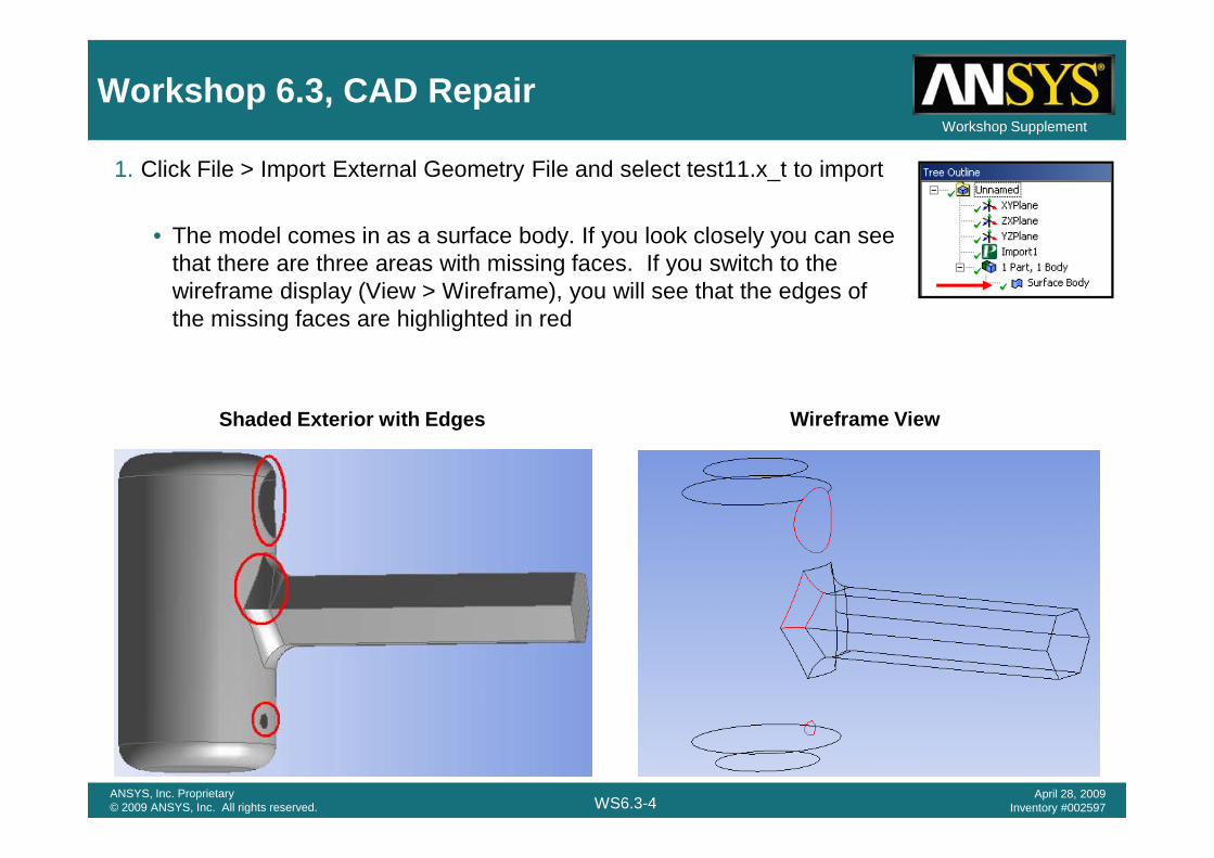
1. Click File > Import External Geometry File and select test11.x_t to import
• The model comes in as a surface body. If you look closely you can see that there are three areas with missing faces. If you switch to the wireframe display (View > Wireframe), you will see that the edges of the missing faces are highlighted in red
Shaded Exterior with Edges Wireframe View
WS6.3-4ANSYS, Inc. Proprietary© 2009 ANSYS, Inc. All rights reserved.
April 28, 2009Inventory #002597
Shaded Exterior with Edges Wireframe View

Workshop Supplement
Workshop 6.3, Automatic Surface Patches
First fix the small hexagonal patch near the end of the cylinder:2. Select the six edges from the Model View and select Tools > Surface Patch3. Click on Apply in the Patch Edges entry box to select the 6 edges4. Leave the Patch Method set to Automatic and Generate the patch
• Note that a smooth single surface is generated.
WS6.3-5ANSYS, Inc. Proprietary© 2009 ANSYS, Inc. All rights reserved.
April 28, 2009Inventory #002597
Before After

Workshop Supplement
Workshop 6.3, Second Automatic Patch
Next fix the four-sided missing face near the base of the handle:5. Select the four edges from the Model View and select Tools > Surface Patch6. Click on Apply in the Patch Edges entry box to select the 4 edges7. Leave the Patch Method set to Automatic and Generate the patch
– Note that again a smooth single surface is generated. In the Wireframeview, note that the edges for the two missing faces that you’ve fixed withpatches are no longer highlighted in red.
Patch 1
Patch 2
WS6.3-6ANSYS, Inc. Proprietary© 2009 ANSYS, Inc. All rights reserved.
April 28, 2009Inventory #002597
Missing Face

Workshop Supplement
Workshop 6.3, Third Patch – Automatic
• The last area where faces are missing spans regions of two different curvatures and the automatic method will have more difficulty filling it in smoothly. There are two missing edges in this last region.
8. Select the two missing edges from the Model View and select Tools > Surface Patch9. Click on Apply in the Patch Edges entry box to select the edges10. Leave the Patch Method set to Automatic and Generate the patch
– Note the ripples in the surface that’s created. In this case, the Natural Healing method was chosen and the cylindrical surface curvature is not maintained.
WS6.3-7ANSYS, Inc. Proprietary© 2009 ANSYS, Inc. All rights reserved.
April 28, 2009Inventory #002597

Workshop Supplement
Workshop 6.3, Third Patch – Patch Healing
11. Change the Patch Method to Patch Healing and Generate the patchIn this case, the patch is created based on the edges and neither curvature is maintained. There is an apparent “divot” taken out of the model, although it is possible that this is the correct reconstruction.
WS6.3-8ANSYS, Inc. Proprietary© 2009 ANSYS, Inc. All rights reserved.
April 28, 2009Inventory #002597
Neither curvature is respected by the patch

Workshop Supplement
Workshop 6.3, Surface Extension
• The use of the Surface Extension tool can lead to a better quality fix for the missing faces:12. Delete the Surface Patch you created for this face13. Select the shorter edge for the missing face and select Tools > Surface Extension14. Set the Extent Type to Natural and set the Extent to Fixed with a value of 50 mm. Click Generate to
extend the surface.– Note that the missing bit of the end surface is restored and the extended surface stops at the
natural bounds of the face
WS6.3-9ANSYS, Inc. Proprietary© 2009 ANSYS, Inc. All rights reserved.
April 28, 2009Inventory #002597

Workshop Supplement
Workshop 6.3, Final Surface Patch
• With the missing bit of the end surface smoothly restored, an Automatic Surface Patch can be used to restore the final missing face:
15. Select the two edges of the missing face from the model view and create a Surface Patchwith the Method set to Automatic. Click Generate.
– Note that a smooth surface is created which follows the curvature of the cylinder
WS6.3-10ANSYS, Inc. Proprietary© 2009 ANSYS, Inc. All rights reserved.
April 28, 2009Inventory #002597

Workshop Supplement
Workshop 6.3, Sew Body Operation
• Although there are no longer any missing faces, the model still consists of a single surface body
• Since the body encloses a volume, it can be converted to a solid using the Sew Body Operation
WS6.3-11ANSYS, Inc. Proprietary© 2009 ANSYS, Inc. All rights reserved.
April 28, 2009Inventory #002597

Workshop Supplement
Workshop 6.3, Sew Body Operation
16. Select Create > Body Operation 17. Select the Body18. Set the Type to Sew and set the Create Solids?
toggle to Yes19. Click Generate to convert the Surface Body to a
Solid– Note the change in the Model Tree
WS6.3-12ANSYS, Inc. Proprietary© 2009 ANSYS, Inc. All rights reserved.
April 28, 2009Inventory #002597

Workshop 7.1
Pulley Model with
WS7.1-1ANSYS, Inc. Proprietary© 2009 ANSYS, Inc. All rights reserved.
April 28, 2009Inventory #002597
Pulley Model with Parameters
DesignModeler

Workshop Supplement
Workshop 7.1, Pulley Model with Parameters
• Goals:– Create a 3D model through
sketching and extruding– Add a revolved feature to
represent the pulley’s groove– Add a bolt hole pattern with one
sketch that is based on a construction sketch
– Parameterize the model so the pulley size automatically updates
WS7.1-2ANSYS, Inc. Proprietary© 2009 ANSYS, Inc. All rights reserved.
April 28, 2009Inventory #002597
pulley size automatically updates the bolt hole pattern. A whole range of pulley sizes could now be simulated!
• Start Page setup:– Double click on Geometry under
Component Systems to create a new geometry
– Double click on Geometry in Project Schematic panel to start Design Modeler
– At the prompt, set the length unit to millimeter

Workshop Supplement
Create a sketch on the XYPlane:In Tree, click on >XYPlane to activate it.
Toolbar “Look At”
1. [Sketching] > Draw > Circle
1
Workshop 7.1, Pulley Model with Parameters
WS7.1-3ANSYS, Inc. Proprietary© 2009 ANSYS, Inc. All rights reserved.
April 28, 2009Inventory #002597
Note: selecting the Sketching tab after selecting a plane changes to Sketching mode and automatically creates a new sketch if one does not exist
1

Workshop Supplement
Create a sketch on the XYPlane (cont’d):• Select origin for center of circle
2. Put the cursor near the global origin. You should see a “P” appear near your cursor, indicating an auto-constraint will be applied. Click once with the left mouse button.
• Select an arbitrary point for diameter of circle3. Click on the screen to define the radius of
the circle. The actual value does not
34
Workshop 7.1, Pulley Model with Parameters
WS7.1-4ANSYS, Inc. Proprietary© 2009 ANSYS, Inc. All rights reserved.
April 28, 2009Inventory #002597
the circle. The actual value does not matter, as we will dimension this next.
• [Sketching] > Dimensions > General4. RMB and choose Diameter dimensioning,
then click on the circle. Click again on the screen to place the dimension.
• Details View: Dimensions > D15. Click on the text box value next to “D1”.
This will highlight the text entry field. Enter “60” for the value of D1. This redefines the diameter as 60 millimeters.
2
5

Workshop Supplement
Extrude the circle to create a cylinder• Graphics View: Select Iso View ball
6. Select the light-blue iso-ball on the triad to change to isometric view.
• Toolbar: Extrude7. Select the Extrude icon on
the 3D Features Toolbar.
9
7
Workshop 7.1, Pulley Model with Parameters
WS7.1-5ANSYS, Inc. Proprietary© 2009 ANSYS, Inc. All rights reserved.
April 28, 2009Inventory #002597
• Details View: FD1, Depth (>0)8. Select the text entry box next
to “FD1, Depth (>0)” in the Details View. Enter a value of “10” to extrude the sketch 10 millimeters in the positive z-direction.
• Toolbar: Generate9. Select the Generate icon on
the Toolbar to generate the cylinder.
8
6

Workshop Supplement
Toolbar: “Look At” icon (XYPlane is already active)
Toolbar: “New Sketch” (creates Sketch2 on XY plane)
[Sketching] > Draw > Polygon n=510. Put the cursor near the global
origin. You should see a “P” appear near your cursor, indicating an auto-constraint of
11
Workshop 7.1, Pulley Model with Parameters
WS7.1-6ANSYS, Inc. Proprietary© 2009 ANSYS, Inc. All rights reserved.
April 28, 2009Inventory #002597
indicating an auto-constraint of “Coincident Point” will be applied. Click once with the left mouse button to define the center of the polygon
11. Put the cursor near the positive Y axis. You should see a “C” appear near the cursor indicating the point is coincident to the Y axis. Click once with the left mouse button to define the top vertex location
10

Workshop Supplement
Dimension the 5 sided polygon[Sketching] > Dimensions >
Vertical12. Dimensions the polygon as
Workshop 7.1, Pulley Model with Parameters
WS7.1-7ANSYS, Inc. Proprietary© 2009 ANSYS, Inc. All rights reserved.
April 28, 2009Inventory #002597
12. Dimensions the polygon as shown at right.
13. Select the text entry box next to “V2” and enter a value of 20 mm.
13
12

Workshop Supplement
Create the holes for the bolt pattern:Note: XYPlane is still active
Toolbar: “New Sketch” icon (creates Sketch3 on XY plane)
Toolbar: “Look At” icon[Sketching] > Draw > Circle14. Put the cursor near the top vertex
until a “P” appears near your cursor, indicating an auto-constraint
14
Workshop 7.1, Pulley Model with Parameters
WS7.1-8ANSYS, Inc. Proprietary© 2009 ANSYS, Inc. All rights reserved.
April 28, 2009Inventory #002597
If you inadvertently fail to apply auto constraints, you can undo the selection and try again, or use >Constraints tab and apply them manually
cursor, indicating an auto-constraint will be applied. Click to define the center of the circle then drag the cursor to define the circle radius.
15. Repeat the above step at each of the (5) vertices of the polygon.
! IMPORTANT: watch for the “R” to appear next to the cursor before clicking to define each radius. This indicates the new circle is radiallyconstrained to the previous circle.
!
15

Workshop Supplement
Dimension the top circle:[Sketching] > Dimensions > Diameter
16. Click on the top circle created in step 14.17. Specify 5mm diameter in the dimension Detail.
• Note: Vary the dimension several times to see if all circles update to the new value. Can use >Dimensions>Animate too! Remember to make final dimension 5 mm before moving on to the next step.
Workshop 7.1, Pulley Model with Parameters
WS7.1-9ANSYS, Inc. Proprietary© 2009 ANSYS, Inc. All rights reserved.
April 28, 2009Inventory #002597
17
16
8 mm

Workshop Supplement
Extrude Sketch 3 to create the bolt holesToolbar: Extrude• Details:
20
Workshop 7.1, Pulley Model with Parameters
WS7.1-10ANSYS, Inc. Proprietary© 2009 ANSYS, Inc. All rights reserved.
April 28, 2009Inventory #002597
• Details:18. Operation: “Cut
Material”19. Type: “Through All”
20. “Generate”
1918

Workshop Supplement
Create a sketch to revolve around the pulley in order to define the pulley groove
21. Click on >ZXPlane in Tree to make it active22. Toolbar: “New Sketch”• Toolbar: “Look At” icon• Sketching: Draw > Rectangle
– Draw a rectangle in the approximate location shown
22
Workshop 7.1, Pulley Model with Parameters
WS7.1-11ANSYS, Inc. Proprietary© 2009 ANSYS, Inc. All rights reserved.
April 28, 2009Inventory #002597
21

Workshop Supplement
Dimension the sketch23. [Sketching] > Dimensions Using the dimension toolbox add dimensions as shown
Workshop 7.1, Pulley Model with Parameters
WS7.1-12ANSYS, Inc. Proprietary© 2009 ANSYS, Inc. All rights reserved.
April 28, 2009Inventory #002597
Name and/or Value can be activated in
Dimensions/Display to show the variable names and theirs
values

Workshop Supplement
24. Toolbar: Revolve 25. Click on the Z axis in the
graphics window
Create the pulley groove by revolving the sketch> Modeling>ZXPlane > Sketch4
2429
25
Workshop 7.1, Pulley Model with Parameters
WS7.1-13ANSYS, Inc. Proprietary© 2009 ANSYS, Inc. All rights reserved.
April 28, 2009Inventory #002597
graphics window26. Click >Apply27. Change the Operation to
“Cut Material”28. Check the “FD1, Angle”.
Change it to 360 if different
29. Generate30. Click on the Blue Triad
ISO Ball as desired.
28
27
25
26
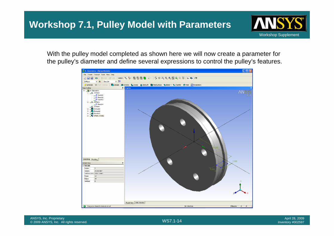
Workshop Supplement
With the pulley model completed as shown here we will now create a parameter for the pulley’s diameter and define several expressions to control the pulley’s features.
Workshop 7.1, Pulley Model with Parameters
WS7.1-14ANSYS, Inc. Proprietary© 2009 ANSYS, Inc. All rights reserved.
April 28, 2009Inventory #002597

Workshop Supplement
[Modeling Tree] >XYPlane > Sketch131. In the Sketch1 Detail check the box next to D1
This action will immediately cause a dialog box to be displayed containing the default dimension name.
32. Enter “Pulley_Diameter” in the dialog box to name the parameter then OK.
Workshop 7.1, Pulley Model with Parameters
WS7.1-15ANSYS, Inc. Proprietary© 2009 ANSYS, Inc. All rights reserved.
April 28, 2009Inventory #002597
30
31
Once accepted the diameter a Parameter Set tree is
created in the Project
Schematic window

Workshop Supplement
Note: We have now made the pulley diameter a parametric value. Since our goal is to “drive” the other dimensions to automatically reflect any diameter change, we’ll now create several expressions for that purpose. In particular, there are 2 dimensions we need to control, the hole pattern dimension and the pulley’s groove radius (see below).
Recall the original dimensions were:Pulley diameter = 60
Workshop 7.1, Pulley Model with Parameters
WS7.1-16ANSYS, Inc. Proprietary© 2009 ANSYS, Inc. All rights reserved.
April 28, 2009Inventory #002597
Pulley diameter = 60Hole pattern = 20Groove radius = 28
The desired formulae are:a) Hole pattern placement:
• Dimension = (Pulley_Diameter) / 3b) Pulley groove diameter:
• Dimension = (Pulley_Diameter)/2 - 2

Workshop Supplement
Toolbar: Parameters33. Click on the “Parameter/Dimension
Assignments” tab to enter equations.• NOTE: Your default parameter
names may be different depending on the order and type of Dimensions placed.
Activate the parameter manager via the toolbar icon
Hole Pattern Size is Dia/3
Workshop 7.1, Pulley Model with Parameters
WS7.1-17ANSYS, Inc. Proprietary© 2009 ANSYS, Inc. All rights reserved.
April 28, 2009Inventory #002597
placed.• Click on your various sketches in the
Tree to display your default names in the Detail Window
• This equation is for the overall size of the bolt pattern that lies on the XY plane
• This equation is for the groove sketch radial dimension line. This sketch lies on the ZX plane
32
Hole Pattern Size is Dia/3
The Groove is placed at “Dia/2 minus 2mm”The “minus 2” insures it always
cuts a 2mm deep groove.Note: Your default parameter names may be different

Workshop Supplement
Return to the “Design Parameter” tabExperiment with new values for “Pulley_Diameter” and click “>Check” tab after each change. Notice the “driven” dimensions can be viewed and evaluated with their updated values.
Workshop 7.1, Pulley Model with Parameters
WS7.1-18ANSYS, Inc. Proprietary© 2009 ANSYS, Inc. All rights reserved.
April 28, 2009Inventory #002597
Pulley_Diameter = 150 mm
Pulley_Diameter = 40 mm
• The default parameter names may be different• After checking, click on Generate icon to resume the geometry

Workshop Supplement
Once again, experiment with new values for “Pulley_Diameter”, this time “generating” the model after each change. Note how all model
Workshop 7.1, Pulley Model with Parameters
WS7.1-19ANSYS, Inc. Proprietary© 2009 ANSYS, Inc. All rights reserved.
April 28, 2009Inventory #002597
Note how all model dimensions update simultaneously. This could represent an entire range of pulley sizes (part family) or a series of design variations to used in optimization.

Workshop Supplement
Appendix: Project Schematic parameter data
WS7.1-20ANSYS, Inc. Proprietary© 2009 ANSYS, Inc. All rights reserved.
April 28, 2009Inventory #002597

Workshop Supplement
Appendix: Project Schematic and in design parameter change
1
2
WS7.1-21ANSYS, Inc. Proprietary© 2009 ANSYS, Inc. All rights reserved.
April 28, 2009Inventory #002597
3

Workshop 8.1
Line and Surface Bodies
WS8.1-1ANSYS, Inc. Proprietary© 2009 ANSYS, Inc. All rights reserved.
April 28, 2009Inventory #002597
DesignModeler

Workshop Supplement
Workshop 8.1, Line and Surface Bodies
•Goals:– Create a sketch representing beams used to stiffen a
panel.– Create a line body from the sketch. – Choose a beam cross section to be used and assign it
to the line body.– Create a surface model representing the panel.
WS8.1-2ANSYS, Inc. Proprietary© 2009 ANSYS, Inc. All rights reserved.
April 28, 2009Inventory #002597
– Create a surface model representing the panel.

Workshop Supplement
Workshop 8.1, Line and Surface Bodies
• Project Page>Component Systems>Geometry
WS8.1-3ANSYS, Inc. Proprietary© 2009 ANSYS, Inc. All rights reserved.
April 28, 2009Inventory #002597

Workshop Supplement
Workshop 8.1, Line and Surface Bodies
• Project Page>Component Systems>Geometry
a
b RMB
WS8.1-4ANSYS, Inc. Proprietary© 2009 ANSYS, Inc. All rights reserved.
April 28, 2009Inventory #002597
• DM will Open. When prompted choose “mm” as the length unit

Workshop Supplement
Create a rectangle in the XY Plane[Sketch] > Rectangle
1. Place the cursor near the origin until ‘P’ appears, click then drag to define the rectangle
Click “>Look At” & “>Zoom to Fit” tool buttons, and Triad ISO Ball as
Workshop 8.1, Line and Surface Bodies
WS8.1-5ANSYS, Inc. Proprietary© 2009 ANSYS, Inc. All rights reserved.
April 28, 2009Inventory #002597
tool buttons, and Triad ISO Ball as desired.
1

Workshop Supplement
Dimension the rectangle 600X300 mm as shown[Sketch] > Dimension > GeneralHorizontal = 600 mmVertical = 300 mm
Fit the sketch and move dimensions as necessary[Sketch] > Dimension > Move
Workshop 8.1, Line and Surface Bodies
WS8.1-6ANSYS, Inc. Proprietary© 2009 ANSYS, Inc. All rights reserved.
April 28, 2009Inventory #002597

Workshop Supplement
Add 2 vertical lines and dimension as shown[Sketch] > Draw > Line2. Place the cursor near the top line
until the ‘C’ coincidence constraint appears. Move the cursor to the bottom line until the ‘C’ appears and a ‘V’ indicating a vertical constraint.
3. Repeat for second line
Workshop 8.1, Line and Surface Bodies
WS8.1-7ANSYS, Inc. Proprietary© 2009 ANSYS, Inc. All rights reserved.
April 28, 2009Inventory #002597
Apply horizontal dimensions as shown.[Sketch] > Dimension > HorizontalAdjust Details so all dimensions are as indicated
1 2

Workshop Supplement
Create a Line Body from Sketch1[Main Menu] > Concept > Lines From Sketches4. Select “Sketch1” from the Tree (click the “+”
near the XYPlane to expand that branch if necessary) and “>Details>Apply” it as the base object
5. Click >Generate
Workshop 8.1, Line and Surface Bodies
WS8.1-8ANSYS, Inc. Proprietary© 2009 ANSYS, Inc. All rights reserved.
April 28, 2009Inventory #002597

Workshop Supplement
Select a rectangular tube type cross section: [Main Menu] > Concept > Cross Section > Rectangular TubeAfter selection, the cross section is displayed with its dimensions.
In this case we will use the default dimensions.
Workshop 8.1, Line and Surface Bodies
WS8.1-9ANSYS, Inc. Proprietary© 2009 ANSYS, Inc. All rights reserved.
April 28, 2009Inventory #002597
If desired the cross section Details can be changed to modify the cross section.

Workshop Supplement
With a cross section selected we now need to associate it with our line body.6. Highlight the line body in the tree
and the details shows that no cross section is yet associated with it.[tree] > 1 Part, 1 Body > Line Body (at bottom of tree)
7. Click in the “Cross Section” field
Workshop 8.1, Line and Surface Bodies
WS8.1-10ANSYS, Inc. Proprietary© 2009 ANSYS, Inc. All rights reserved.
April 28, 2009Inventory #002597
8. Choose “RecTube1” from the drop down list

Workshop Supplement
9. After assigning the cross section to the line body the default display shows the line body with its cross section alignment (see right). We can also display the beam with the cross section displayed as a solid.
[Main Menu] > View > Show Cross Sections Solids
Workshop 8.1, Line and Surface Bodies
WS8.1-11ANSYS, Inc. Proprietary© 2009 ANSYS, Inc. All rights reserved.
April 28, 2009Inventory #002597

Workshop Supplement
The next step is to create the surfaces between the beams. These surfaces will be shell meshed in the MECHANICAL.10. [Main Menu] > Concept >
Surfaces From EdgesHold the control key and select the 4 lines shown at right.(or can hold down LMB and sweep mouse over lines to be group selected)
10
Workshop 8.1, Line and Surface Bodies
WS8.1-12ANSYS, Inc. Proprietary© 2009 ANSYS, Inc. All rights reserved.
April 28, 2009Inventory #002597
selected)11. >Apply
11

Workshop Supplement
12. “>Generate” the Surface Body.Note: a frozen surface body is created, bounded by the selected lines
Repeat the previous steps to create two more surface bodies
“>Generate” as necessary
Workshop 8.1, Line and Surface Bodies
WS8.1-13ANSYS, Inc. Proprietary© 2009 ANSYS, Inc. All rights reserved.
April 28, 2009Inventory #002597
12

Workshop Supplement
The final modeling operation is to place all the bodies into a single part (multi-body part). We must do this to insure that, when meshed, each boundary “recognizes” its neighbor resulting in a continuous mesh.Set the Selection Filter to “Bodies”. In the graphics window right mouse click and choose “>Select
Workshop 8.1, Line and Surface Bodies
WS8.1-14ANSYS, Inc. Proprietary© 2009 ANSYS, Inc. All rights reserved.
April 28, 2009Inventory #002597
mouse click and choose “>Select All”

Workshop Supplement
With all bodies selected, again right click in the graphics window and choose “Form New Part”.
By examining the Tree notice a single part has been formed which contains 4 bodies.
Workshop 8.1, Line and Surface Bodies
WS8.1-15ANSYS, Inc. Proprietary© 2009 ANSYS, Inc. All rights reserved.
April 28, 2009Inventory #002597

Workshop Supplement
• Shown here we have moved to a MECHANICAL environment in Workbench and meshed the geometry.
– By grouping all bodies into a common (single) part, nodal connectivity
is insured.
Workshop 8.1, Line and Surface Bodies
WS8.1-16ANSYS, Inc. Proprietary© 2009 ANSYS, Inc. All rights reserved.
April 28, 2009Inventory #002597