workshop practice-ii (mep-302)
TRANSCRIPT

SCTEVT DIPLOMA LAB MANUAL FOR WORK SHOP PRACTICE – II, 3rd Semester, Mechanical Engg. Page 1
WORKSHOP PRACTICE-II (MEP-302)
CONTENTS
Name of the Experiment Page No.
FITTING PRACTICES:-
• Preparation of calliper 02
• Preparation of try square 03
• Preparation of hammer 04
• Preparation of male-female joint 05
CARPENTRY PRACTICES:-
• Cutting of slot, botch, mortise and Tenon 06
• Preparation of single dove tail joint 07
METAL MACHINING PRACTICES:-
• Plain turning & Step turning 08
• Taper turning & Grooving 09
• Chamfering & External threading 10
SMITHY PRACTICES:-
• Preparation of door ring with hook 11
• Preparation of hexagonal head bolt 12
• Preparation of octagonal flat chisel 13

SCTEVT DIPLOMA LAB MANUAL FOR WORK SHOP PRACTICE – II, 3rd Semester, Mechanical Engg. Page 2
EXPERIMENT NO- 01
AIM OF THE EXPERIEMENT:-
To prepare a calliper.
APPARATUS REQUIRED :-
SL
NO NAME OF THE ITEMS SPECIFICATION QUANTITY
01 Hacksaw frame with blade 300mm 01
02 Bastard File 300mm 01
03 Smooth File 250mm 01
04 Hammer 0.25Kg 01
05 Punch 150mm 01
06 Steel Rule 300mm 01
07 Drill Bit Ø6mm 01
08 Marking Media As per requirement
09 Drilling Machine Bench Type 01
RAW MATERIAL REQUIRED:-
SL
NO NAME OF THE ITEMS SPECIFICATION QUANTITY
01 M.S. Flat 2 (160X20X6)mm 02
02 M.S. Rivet Ø6mmX10mm 01
PROCEDURE:-
➢ File the two adjacent edges of the M.S Flat to right angle.
➢ Apply the marking media to mark the job as per sketch and punch the marking line.
➢ Remove the extra material by sawing and chipping and then file the job to the
required shape.
➢ Drill the holes on the two pieces and clean the burrs.
➢ Assemble the two parts by riveting.
➢ Finish all sides, edges and surfaces properly.
CONCLUSION:-
Hence the outside calliper is made and required dimension has prepared.
SCTEVT DIPLOMA LAB MANUAL FOR WORK SHOP PRACTICE – II, 3rd Semester, Mechanical Engg. Page 3
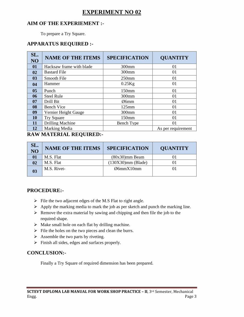
EXPERIMENT NO 02
AIM OF THE EXPERIEMENT :-
To prepare a Try Square.
APPARATUS REQUIRED :-
SL.
NO NAME OF THE ITEMS SPECIFICATION QUANTITY
01 Hacksaw frame with blade 300mm 01
02 Bastard File 300mm 01
03 Smooth File 250mm 01
04 Hammer 0.25Kg 01
05 Punch 150mm 01
06 Steel Rule 300mm 01
07 Drill Bit Ø6mm 01
08 Bench Vice 125mm 01
09 Vernier Height Gauge 300mm 01
10 Try Square 150mm 01
11 Drilling Machine Bench Type 01
12 Marking Media As per requirement
RAW MATERIAL REQUIRED:-
SL.
NO NAME OF THE ITEMS SPECIFICATION QUANTITY
01 M.S. Flat (80x30)mm Beam 01
02 M.S. Flat (130X30)mm (Blade) 01
03 M.S. Rivet- Ø6mmX10mm
01
PROCEDURE:-
➢ File the two adjacent edges of the M.S Flat to right angle.
➢ Apply the marking media to mark the job as per sketch and punch the marking line.
➢ Remove the extra material by sawing and chipping and then file the job to the
required shape.
➢ Make small hole on each flat by drilling machine.
➢ File the holes on the two pieces and clean the burrs.
➢ Assemble the two parts by riveting.
➢ Finish all sides, edges and surfaces properly.
CONCLUSION:-
Finally a Try Square of required dimension has been prepared.

SCTEVT DIPLOMA LAB MANUAL FOR WORK SHOP PRACTICE – II, 3rd Semester, Mechanical Engg. Page 4
EXPERIMENT NO- 03
AIM OF THE EXPERIEMENT :-
To prepare a Hammer.
APPARATUS REQUIRED :-
SL.
NO NAME OF THE ITEMS SPECIFICATION QUANTITY
01 Hacksaw frame with blade 300mm 01
02 Bastard File 300mm 01
03 Smooth File 250mm 01
04 Hammer 0.25Kg 01
05 Scriber 150mm 01
06 Lathe Machine Centre Lathe 01
07 Vernier Calliper 200mm 01
08 Bench Vice 125mm 01
09 Lathe Cutting Tool HSS 4” 02
10 Chuck Key - 01
11 Drilling Machine Bench Type 01
RAW MATERIAL REQUIRED:-
SL
NO NAME OF THE ITEMS SPECIFICATION QUANTITY
01 M.S. Rod (Ø40X60)mm 01
02 M.S.Rod ((Ø10X200)mm 01
PROCEDURE:-
➢ At first fit the job in chuck of the lathe with the help of chuck key.
➢ Then fit the cutting tool on the tool post.
➢ Then test whether the job is properly fixed or not on the lathe machine.
➢ After that start all operations to prepare a hammer.
➢ At last complete all the operation and produce a hammer
CONCLUSION:-
Hence a hammer is prepared as per the given dimension.

SCTEVT DIPLOMA LAB MANUAL FOR WORK SHOP PRACTICE – II, 3rd Semester, Mechanical Engg. Page 5
EXPERIEMNT NO: 04
AIM OF THE EXPERIEMNET:-
Male and Female fitting.
TOOLS AND EQUIPMENT REQUIRED:-
SL.
NO
NAME OF THE ITEMS SPECIFICATION QUANTITY
01 Bench Vice 125mm 01
02 Hack Saw frame with blade 300mm 01
03 Bastard File 300mm 01
04 Square File 200mm 01
05 Scriber 150mm 01
06 Ball Pen Hammer 0.25Kg 01
07 Centre Point 125mm 01
08 Try Square 150mm 01
09 Odd Leg Calliper 150mm 01
10 Steel Rule 300mm 01
11 Smooth File 250mm 01
12 Vernier Calliper 200mm 01
RAW MATERIAL REQUIRED:-
SL
NO NAME OF THE ITEMS SPECIFICATION QUANTITY
01 M.S. Flat (50X50X6)mm 01
PROCEDURE:-
➢ First check the raw material size as required.
➢ File two adjacent sides and make the right angle.
➢ Put marking media to mark the job and give punch mark on the marking line.
➢ Cut the extra material by using hack saw.
➢ File all sides , edges and surfaces properly.
➢ First finish the male part then female part and check the dimensions by verniner
calliper.
➢ At last finish and fit the male and female part and complete the job.
CONCLUSION:-
The required male and female fitting is thus obtain by following the stages as
described above.

SCTEVT DIPLOMA LAB MANUAL FOR WORK SHOP PRACTICE – II, 3rd Semester, Mechanical Engg. Page 6
EXPERIEMNT NO: 05
AIM OF THE EXPERIEMNET:-
Cutting of slot, notch, mortise and tenon.
TOOLS AND EQUIPMENT REQUIRED:-
SL. NO NAME OF THE ITEMS SPECIFICATION QUANTITY 01 Carpenter’s Vice 600mm 01
02 Steel Rule 300mm 01
03 Jack Plane 250mm 01
04 Try Square 150mm 01
05 Marking Gauge 150mm 01
06 Firmer Chisel 25mm 01
07 Mortise Chisel 6mm 01
08 Cross Cut Saw 300mm 01
09 Tenon Saw 250mm 01
10 Scriber 150mm 01
11 Mallet 0.25Kg 01
RAW MATERIAL REQUIRED:-
SL NO NAME OF THE ITEMS SPECIFICATION QUANTITY
01 Wood Size (50X50X250) mm 01
PROCEDURE:
➢ The given raw material is checked to ensure its correct size.
➢ The material is firmly clamped in the carpenter’s vice and one of its faces are planned by
the jack plane and checked for straightness.
➢ The adjacent face is then planed and the faces are checked for squareness with the try
square.
➢ Marking gauge is set and lines are drawn at 30 and 45mm to mark the thickness and
width of the model respectively.
➢ The excess material is first chiselled out with the firmer chisel and then planned to correct
size.
➢ The matching dimension of the part X and Y are then marked using the scale and marking
gauge.
➢ Using the cross cut saw the portions to be removed in part Y (Tenon) is cut followed by
chiselling.
➢ The material to be removed in Part X (Mortise) is carried out by using the mortise and
firmer chisel.
➢ The part X and Y are separated by cross cutting with the tenon saw.
➢ The ends of both the part are chiselled to exact length.
➢ Finish chiselling is done where ever needed so that the parts can be fitted to obtain a near
tight joint.
CONCLUSION: -The mortise and tenon joint is thus made by following the above
sequence of operations.

SCTEVT DIPLOMA LAB MANUAL FOR WORK SHOP PRACTICE – II, 3rd Semester, Mechanical Engg. Page 7
EXPERIEMNT: 06
AIM OF THE EXPERIEMNET:-
To prepare a single Dove Tail joints
TOOLS AND EQUIPMENT REQUIRED:-
SL.
NO
NAME OF THE ITEMS SPECIFICATION QUANTITY
01 Carpenter’s Vice 600mm 01
02 Steel Rule 300mm 01
03 Jack Plane 250mm 01
04 Try Square 150mm 01
05 Marking Gauge 150mm 01
06 Firmer Chisel 25mm 01
07 Mortise Chisel 6mm 01
08 Cross Cut Saw 300mm 01
09 Tenon Saw 250mm 01
10 Scriber 150mm 01
11 Mallet 0.25Kg 01
RAW MATERIAL REQUIRED:-
SL NO
NAME OF THE ITEMS SPECIFICATION QUANTITY
01 Wood Size (50X50X250)mm 01
PROCEDURE:
➢ The give raw material is checked to ensure its correct size.
➢ The material is firmly clamped in the carpenter’s vice and any two adjacent
faces are planned by the jack plane and checked for straightness.
➢ The adjacent face is then planed and the faces are checked for squareness with
the try square.
➢ Marking gauge is set and lines are drawn at 30 and 45mm to mark the
thickness and width of the model respectively.
➢ The excess material is first chiselled out with the firmer chisel and then
planned to correct size.
➢ The matching dimension of the part X and Y are then marked using the scale
and marking gauge.
➢ Using the cross cut saw the portions to be removed in part Y (Tenon) is cut
followed by chiselling.
➢ The part X and Y are separated by cross cutting with the tenon saw.
➢ The ends of both the part are chiselled to exact length.
➢ A fine finishing is given to the parts if required so that proper fitting is
obtained.
➢ The parts are fitted to obtain a slightly tight joint.
CONCLUSION: -The single Dove Tail joint is thus made by following the above
sequence of operations.

SCTEVT DIPLOMA LAB MANUAL FOR WORK SHOP PRACTICE – II, 3rd Semester, Mechanical Engg. Page 8
EXPERIEMNT NO: 07
AIM OF THE EXPERIEMNET:-
Plain turning and step turning
TOOLS AND EQUIPMENT REQUIRED:-
SL.
NO
NAME OF THE ITEMS SPECIFICATION QUANTITY
01 Chuck Key - 01
02 Steel Rule 300mm 01
03 Vernier Calliper 300mm 01
04 Surface Gauge 150mm 01
05 Box Spanner - 01
06 Single Point Cutting Tool HSS 4” 01
RAW MATERIAL REQUIRED:-
SL
NO NAME OF THE ITEMS SPECIFICATION QUANTITY
01 M.S. Rod Ø35X100mm 01
PROCEDURE:
➢ Fit the job in the chuck of the lathe with the help of chuck key.
➢ Fit the cutting tool on the tool post.
➢ Test the job whether it is properly fitted or not by surface gauge.
➢ Now start the machine and do plane turning by giving small feed to the cutting tool
and by moving the hand wheel of the carriage.
➢ Then when the entire length of the work piece is turned , start step turning.
➢ Step turning is done on the required length of the job as per sketch. The step turning
diameter is also given in the sketch.
➢ Step turning is done by giving more cross feed movement to the cutting tool as per
diameter required.
➢ Repeat the above steps till the required diameter is achieved.
➢ Measure the accurate dia. by using a vernier calliper and finish the step turning.
CONCLUSION:
Finally we obtained a job with required shape and dimension by help of plane turning
and step turning.

SCTEVT DIPLOMA LAB MANUAL FOR WORK SHOP PRACTICE – II, 3rd Semester, Mechanical Engg. Page 9
EXPERIEMNT NO: 08
AIM OF THE EXPERIEMNET:-
Taper turning and grooving operation.
TOOLS AND EQUIPMENT REQUIRED:-
SL.
NO
NAME OF THE ITEMS SPECIFICATION QUANTITY
01 Chuck Key - 01
02 Steel Rule 300mm 01
03 Vernier Calliper 300mm 01
04 Surface Gauge 150mm 01
05 Box Spanner - 01
06 Single Point Cutting Tool HSS 4” 01
07 D.Spanner 14-15 01
RAW MATERIAL REQUIRED:-
SL
NO NAME OF THE ITEMS SPECIFICATION QUANTITY
01 M.S. Rod Ø35X100mm 01
RELATED FORMULA:
Taper formula =tan-1(𝑫−𝒅
𝟐𝒍)
Where D = Larger diameter = 30mm
D = Smaller diameter = 15mm
L = Length of tapper = 30mm
So, =tan-1(𝑫−𝒅
𝟐𝒍)=tan-1(
30−15
2 𝑋 30) = 1402’ 150
PROCEDURE:
➢ Properly fit the job in the chuck of the lathe machine.
➢ Perform plane turning operation on entire length of the job up to dia 35mm.
➢ Then leave 30mm from left and do step turning operation on 20mm length till the dia
reach 30mm.
➢ Now remove cutting tool and fit the grooving tool in the tool post.
➢ Do grooving operation in 5mm lengthup to dia. 20mm as per sketch by the grooving
tool.
➢ Then remove grooving tool and enter cutting tool.
➢ Then tapper turning is done on next 30mm length as shown in sketch.
➢ Tapper turning is done by setting the compound slide at an angle calculated above
(that is = 150) moving carriage along length of tapper.
CONCLUSION:-
Finally we obtain the required shape and size of the job by tapper turning and
grooving operation.

SCTEVT DIPLOMA LAB MANUAL FOR WORK SHOP PRACTICE – II, 3rd Semester, Mechanical Engg. Page 10
EXPERIEMNT NO: 09
AIM OF THE EXPERIEMNET:-
Chamfering and external threading.
TOOLS AND EQUIPMENT REQUIRED:-
SL.
NO
NAME OF THE ITEMS SPECIFICATION QUANTITY
01 Chuck Key - 01
02 Steel Rule 300mm 01
03 Vernier Calliper 300mm 01
04 Surface Gauge 150mm 01
05 Box Spanner - 01
06 Single Point Cutting Tool HSS 4” 01
07 D.Spanner 14-15 01
RAW MATERIAL REQUIRED:-
SL
NO NAME OF THE ITEMS SPECIFICATION QUANTITY
01 M.S. Rod Ø35X100mm 01
PROCEDURE:-
➢ Fit the job in the lathe machine chuck.
➢ Do plane turning and step turning as per sketch.
➢ Set the compound slide at 450 and do chamfering by the chamfer tool on the required
dimension as per sketch.
➢ Then set the gear box for external threading and connect the carriage with the lead
screw.
➢ Then start the external threading operation on the required length as shown in figure.
CONCLUSION:-
The chamfering and external threading operation is done on the job by following the
above procedure.

SCTEVT DIPLOMA LAB MANUAL FOR WORK SHOP PRACTICE – II, 3rd Semester, Mechanical Engg. Page 11
EXPERIMENT NO- 10
AIM OF THE EXPERIEMENT:-
To Prepare a Door ring with Hook.
APPARATUS REQUIRED:-
SL.
NO NAME OF THE ITEMS SPECIFICATION QUANTITY
01 Round Nose Tong 300mm 01
02 Hammer 2Kg and 1.25Kg 02
03 Anvil 50Kg 01
04 Swage Bock 80Kg 01
05 Forge or Hearth - 01
RAW MATERIAL REQUIRED:-
SL
NO NAME OF THE ITEMS SPECIFICATION QUANTITY
01 M.S. Rod Ø10X100mm 01
02 M.S. Rod Ø6X100 mm
01
PROCEDURE:-
➢ At first maintain the required size of the M.S. Rod.
➢ Now put the two M.S. Rods in the previously burning hearth.
➢ The M.S. Rod takes heat from the hearth and its temperature begins to increase.
➢ When its temperature reaches 10000C to 12000C approx., it comes to red hot stage.
➢ Now remove the M.S. Rod from the hearth and hammering it on the anvil to the
required shape.
➢ Then fitted the hook with the ring.
CONCLUSION:-
Finally a door ring with hook as shown in figure is prepared.
SCTEVT DIPLOMA LAB MANUAL FOR WORK SHOP PRACTICE – II, 3rd Semester, Mechanical Engg. Page 12
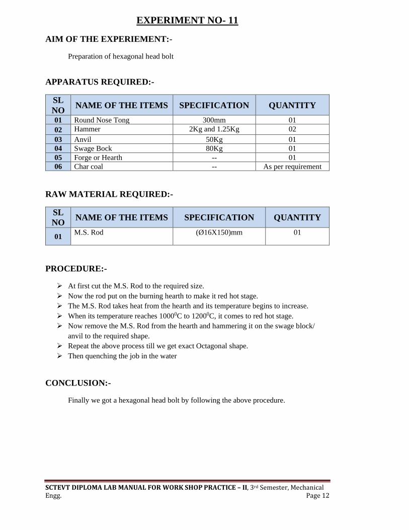
EXPERIMENT NO- 11
AIM OF THE EXPERIEMENT:-
Preparation of hexagonal head bolt
APPARATUS REQUIRED:-
SL
NO NAME OF THE ITEMS SPECIFICATION QUANTITY
01 Round Nose Tong 300mm 01
02 Hammer 2Kg and 1.25Kg 02
03 Anvil 50Kg 01
04 Swage Bock 80Kg 01
05 Forge or Hearth -- 01
06 Char coal -- As per requirement
RAW MATERIAL REQUIRED:-
SL
NO NAME OF THE ITEMS SPECIFICATION QUANTITY
01 M.S. Rod (Ø16X150)mm
01
PROCEDURE:-
➢ At first cut the M.S. Rod to the required size.
➢ Now the rod put on the burning hearth to make it red hot stage.
➢ The M.S. Rod takes heat from the hearth and its temperature begins to increase.
➢ When its temperature reaches 10000C to 12000C, it comes to red hot stage.
➢ Now remove the M.S. Rod from the hearth and hammering it on the swage block/
anvil to the required shape.
➢ Repeat the above process till we get exact Octagonal shape.
➢ Then quenching the job in the water
CONCLUSION:-
Finally we got a hexagonal head bolt by following the above procedure.

SCTEVT DIPLOMA LAB MANUAL FOR WORK SHOP PRACTICE – II, 3rd Semester, Mechanical Engg. Page 13
EXPERIMENT NO- 12
AIM OF THE EXPERIEMENT:-
To Prepare Octagonal Flat Chisel.
APPARATUS REQUIRED:-
SL
NO NAME OF THE ITEMS SPECIFICATION QUANTITY
01 Round Nose Tong 300mm 01
02 Hammer 2Kg and 1.25Kg 02
03 Anvil 50Kg 01
04 Swage Bock 80Kg 01
05 Forge or Hearth -- 01
06 Char coal -- As per requirement
RAW MATERIAL REQUIRED:-
SL
NO NAME OF THE ITEMS SPECIFICATION QUANTITY
01 M.S. Rod (Ø16X150)mm 01
PROCEDURE:-
➢ At first cut the M.S. Rod to the required size.
➢ Now the rod put on the burning hearth to make it red hot stage.
➢ The M.S. Rod takes heat from the hearth and its temperature begins to increase.
➢ When its temperature reaches 10000C to 12000C, it comes to red hot stage.
➢ Now remove the M.S. Rod from the hearth and hammering it on the swage block to
the required shape i.e. octagonal shape.
➢ Repeat the above process till we get exact Octagonal shape.
➢ Then quenching thejob in the water.
CONCLUSION:-
Finally we got an Octagonal Flat Chisel by following the above procedure