workover system information - rig safety. made...
TRANSCRIPT

Workover System Information
V 1.0 June 11, 2015

2
Table of Contents
Display Panel ................................................................................................................. 3
Drill Line Payout ............................................................................................................ 5
Wind Speed Indicator .................................................................................................... 7
Crown Saver .................................................................................................................. 9
Level Indicator ............................................................................................................. 11
Throttle Limiter ............................................................................................................ 13
Air Kill ........................................................................................................................... 15
BOP Ram Sensor......................................................................................................... 17
LED Indicator ............................................................................................................... 19
Pressure Sensor .......................................................................................................... 21
Line Rider ..................................................................................................................... 23
Emergency Shut Down ............................................................................................... 25
Commissioning, Testing and Training ...................................................................... 27

3
Display Panel
Description of Function: The panel is the main display, wireless receiver and control module for the Rigsmart System. Sensor transmissions are received through the panel and clearly displayed for the operator. The panel is the main controller for dumping air and alarming the crew.
Location: The panel is located in the doghouse (or supervisor specified area) and can be mounted to any fixed surface. It is designed for outdoor use in all weather conditions.
Rig Requirements:
Rig Status – The panel is installed while the
rig is racked. A 12 VDC - 24VDC power source from the rig to the Rigsmart power disconnect is required, and technicians must have access to the doghouse (or other specified mounting location).
Crew Responsibilities – The supervisor
should provide a location preference for the panel.
Time Required – 30-60 minutes is required
for panel mounting and setup. Antenna and configuration requirements may vary according to the chosen panel location.
QUICK FACTS Install Time 30-60 Minutes
Rig Status Racked, Moving or Operating
Requirements Location selected by Rig Manager. 12 VDC
- 24VDC power

4
Display Panel Data Sheet Overview The main display, wireless receiver and control module for the Rigsmart System. Sensor transmissions are received through this panel and are clearly displayed for the operator. The Panel is also where logic is loaded, and is the main controller for dumping air before a collision occurs, and alarming the crew. The panel is typically mounted in the doghouse. Operating time 100% (continuous duty) Voltage type 12-24 VDC, 7.5A normal operating range (can accept 11-32 VDC) Operating temperature -40°C to +60°C Operating Frequency Range 900-928 MHz in North America 868-870 MHz in Europe Material Body material – Ultramid 8333G Hi-Polyamide 6 Seals – ROHS compliant silicon rubber, 60 durometer shore-A, compound # SIM40160 Connection Woodhead, bulgin or amphenol Mounting options Bolt on bracket Hazardous locations Class 1 Division 2 Ex nA IIB+H2 T4 Certified to: IEC CAN/CSA E60079-15:02 Environmental Ingress Protection IP67 Application Drilling rigs, Workover rigs, Snubbing units
*Information subject to change without notice. Consult the
factory for the most current data and part numbers.*
Rigsmart Systems, Inc. 4908 97 St. Edmonton, AB T6L 4B2 Ph: 780.438.9475 Email: [email protected]
5
Drill Line Payout
Description of Function:
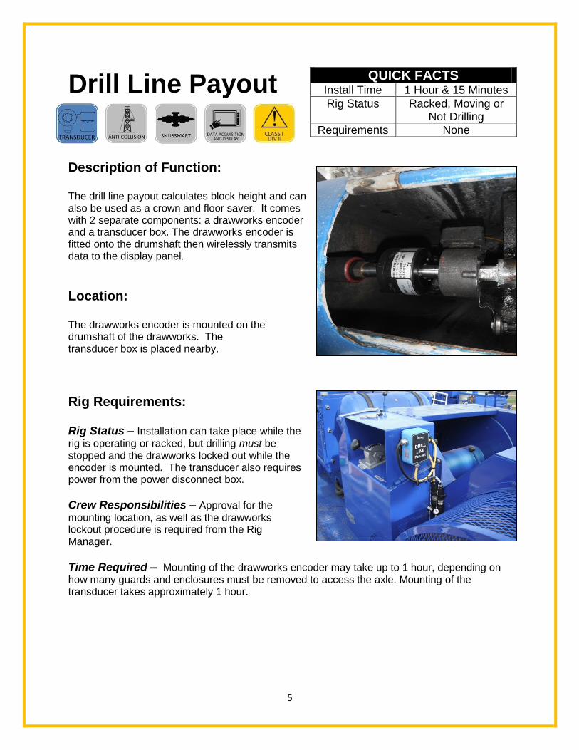
The drill line payout calculates block height and can also be used as a crown and floor saver. It comes with 2 separate components: a drawworks encoder and a transducer box. The drawworks encoder is fitted onto the drumshaft then wirelessly transmits data to the display panel.
Location: The drawworks encoder is mounted on the drumshaft of the drawworks. The transducer box is placed nearby.
Rig Requirements: Rig Status – Installation can take place while the
rig is operating or racked, but drilling must be stopped and the drawworks locked out while the encoder is mounted. The transducer also requires power from the power disconnect box. Crew Responsibilities – Approval for the
mounting location, as well as the drawworks lockout procedure is required from the Rig Manager.
Time Required – Mounting of the drawworks encoder may take up to 1 hour, depending on
how many guards and enclosures must be removed to access the axle. Mounting of the transducer takes approximately 1 hour.
QUICK FACTS Install Time 1 Hour & 15 Minutes
Rig Status Racked, Moving or Not Drilling
Requirements None

6
Drill Line Payout Data Sheet
Overview The drill line payout monitors block height. The block height can then be combined with information from the bail, block, crown, stabbing board and additional wireless sensors to establish an anti-collision routine. It comes with two separate components: a drawworks encoder and a transducer box. The drawworks encoder counts the turning revolutions of the drum as it reels in or out drill line, and sends a corresponding signal to the transducer box for brake and / or speed control. Operating time 100% (continuous duty) Voltage type 12 VDC or 24 VDC supplied by the rig Operating temperature -40°C to +60°C Operating Frequency Range 900-928 MHz in North America 868-870 MHz in Europe Material Body material – Ultramid 8333G Hi-Polyamide 6 Seals – ROHS compliant silicon rubber, 60 durometer shore-A, compound # SIM40160 Connection A power connection from the Rigsmart power supply is required. The component provides a wireless signal. Mounting options Custom brackets are made to fit the drawworks skid. Hazardous locations Ex ia IIB T4 Cl 1, Div 2 CD T4 Certified to: CSA C22.2 NO.213-87M(99) CAN/CSA E60079-15:02 CSA C22.2 NO. 142-87 CEC(2006) Environmental Ingress Protection IP67
*Information subject to change without notice. Consult the
factory for the most current data and part numbers.*
(TO POWER) DRAWWORKS
ENCODER
Rigsmart Systems, Inc. 4908 97 St. Edmonton, AB T6L 4B2 Ph: 780.438.9475 Email: [email protected]

7
Windspeed Indicator
Description of Function: The Rigsmart Windspeed Indicator measures windspeed and temperature on location. Setting an alarm threshold helps to protect against wind loading when the racking board is full of pipe. The temperature and windspeed can also protect crews against extreme cold.
Location: The Windspeed Indicator is usually mounted to the top of the derrick.
Rig Requirements: Rig Status – The windspeed indicator should be mounted when the derrick is down, or as long as climbing safety procedures are followed. Crew Responsibilities – The crew should be aware that the installed windspeed indicator can add length to the rig during rig moves. The crew should understand any maximum length restrictions, and also provide approval of the mounting location. Time Required – Installation typically takes one hour, but may vary with regards to the mounting location.
QUICK FACTS Install Time 1 hour
Rig Status Racked, Moving or Operating
Requirements None

8
Windspeed Indicator Data Sheet Overview A wireless component that measures wind speed and temperature. It is traditionally used in situations where operators are required to shut down operations if the temperature drops too low or winds become too extreme. Operating time 100% (continuous duty) Voltage type Powered by a 3.6 volt D cell lithium battery Operating temperature -40°C to +60°C Operating Frequency Range 900-928 MHz in North America 868-870 MHz in Europe Material Body material – Ultramid 8333G Hi-Polyamide 6 Seals – ROHS compliant silicon rubber, 60 durometer shore-A, compound # SIM40160 Connection No connection, component provides a wireless signal Mounting options Custom fitted to your application Hazardous locations Not rated for hazardous zones Environmental Ingress Protection IP67 Application Drilling or Workover rigs
*Information subject to change without notice. Consult the
factory for the most current data and part numbers.*
Rigsmart Systems, Inc. 4908 97 St. Edmonton, AB T6L 4B2 Ph: 780.438.9475 Email: [email protected]

9
Crown Saver
Description of Function: The crown saver is a strain gauge installed at the crown. It is made up of two main components: the transducer and the counter weight. The transducer is mounted to a fixed point on or near the crown assembly. The counter weight is suspended from the bottom of the transducer, around a slow speed line. Components are safety cabled, and stainless steel mounting hardware prevents corrosion.
Location: The crown saver sensor is mounted to the inside of the derrick, near the bottom of the crown. It may be attached to a weld bar or bolted to a threaded hole.
Rig Requirements: Rig Status – The crown saver is easily installed
while the derrick and crown are on the ground.
Crew Responsibilities – Approval is required for
mounting location, drill and tap, or a weld bar. If necessary, the rig must also supply a welder for instalment.
Time Required - The crown saver takes
approximately 1 hour to install, if the derrick is on the ground. More timemay be required if the work is done at height.
QUICK FACTS Install Time 30 Minutes
Rig Status Derrick laid over, not drilling
Requirements Welded on bracket or threaded hole in crown

10
Rigsmart Systems, Inc. 4908 97 St. Edmonton, AB T6L 4B2 Ph: 780.438.9475 Email: [email protected]
Crown Saver Sensor Data Sheet
Overview A sensor used to monitor a counterweight attached to the slow speed line of a rig travelling block. When the block makes contact with the counterweight, the crown saver sends a signal to apply the rig brakes. Operating time 100% (continuous duty) Voltage type Powered by a 3.6 volt D cell lithium battery
Operating temperature -40°C to +60°C Operating Frequency Range 900-928 MHz in North America 868-870 MHz in Europe Material Body material – – Ultramid 8333G Hi-Polyamide 6 Seals – ROHS compliant silicon rubber, 60 durometer shore-A, compound # SIM40160 Connection No connection, component provides a wireless signal Mounting options A variety of custom fit welds, clamps or brackets are available. All three options provide secondary containment. Hazardous locations Exia IIB T4 Intrinsically Safe per IEC CAN/CSA E60079-11:02 Environmental Ingress Protection IP67 Application Drilling or Workover rigs
*Information subject to change without notice. Consult the
factory for the most current data and part numbers.*

11
Level Indicator
Description of Function: The level indicator is installed to monitor changes in condition of the rig carriage. Ground thaw, wind loading and over-pull are all conditions that can shift a workover unit.
Location: Installed under the catwalk or on derrick cross member.
Rig Requirements: Rig Status – Install when the rig is on true level of a cement pad.
Crew Responsibilities – Approval of the mounting location Time Required – Installation typically takes 1 hour, but may vary with regards to the mounting location.
QUICK FACTS Install Time 1 hour
Rig Status Racked, Moving or Operating
Requirements None

12
Level Indicator Data Sheet Overview
Indicates if the rig is level and the derrick true vertical, sending a signal for alarm if necessary. The sensor is most useful in situations where there may be ground thaw, sinking mud or extreme wind. Operating time 100% (continuous duty) Voltage type Powered by a 3.6 volt D cell lithium battery Operating temperature -40°C to +60°C Operating Frequency Range 900-928 MHz in North America 868-870 MHz in Europe Material Body material – Ultramid 8333G Hi-Polyamide 6 Seals – ROHS compliant silicon rubber, 60 durometer shore-A, compound # SIM40160 Connection No connection, component provides a wireless signal Mounting options Various brackets available to meet application requirements Hazardous locations Exia IIB T4 Intrinsically Safe per IEC CAN/CSA E60079-11:02 Environmental Ingress Protection IP67 Application Drilling or Workover rigs
*Information subject to change without notice. Consult the
factory for the most current data and part numbers.*
Rigsmart Systems, Inc. 4908 97 St. Edmonton, AB T6L 4B2 Ph: 780.438.9475 Email: [email protected]

13
Throttle Limiter
Description of Function: The throttle limiter is a transducer and pneumatics box that can reduce or kill an air controlled engine throttle. This control monitors the block speed and slows the blocks down as collision points are approached. The throttle limiter can be paired with the auxiliary brake controller to slow the traveling blocks in both the up and down directions. Both can be adapted to be used with PLC controlled rigs.
Location: The pneumatics box and transducer is usually located near the engine it’s controlling.
Rig Requirements: Rig Status- The engine being controlled must be shut down for safe installation. Crew responsibilities - Some minor assistance from the crew may be required to identify air
lines.
Time Required- The throttle limiter takes approximately 1 hour to install.
QUICK FACTS Install Time 1 Hour
Rig Status Racked or Moving
Requirements Rig air supply

14
Throttle Limiter Data Sheet
Overview
The Rigsmart Throttle Limiter will pneumatically limit the throttle on the rigs engine in order to prevent a collision or an over-pressure situation. Common applications are drawworks throttles and mud pump throttles. Operating time 100% (continuous duty) Voltage type 12-24 VDC Operating temperature -40°C to +60°C Construction - 16 gauge steel body and cover - Welded seams without knockouts or holes - Seamless poured-in place gasket - Door includes a quarter turn slot for added safety Connection Woodhead, Bulgin or Amphenol Mounting options Enclosure has mounting options Hazardous locations
All internal components are rated for Class1 Division 2 Environmental Ingress Protection IP67 Application Drilling, Snubbing or Workover rigs
*Information subject to change without notice. Consult the
factory for the most current data and part numbers.*
Rigsmart Systems, Inc. 4908 97 St. Edmonton, AB T6L 4B2 Ph: 780.438.9475 Email: [email protected]
15
Air Kill
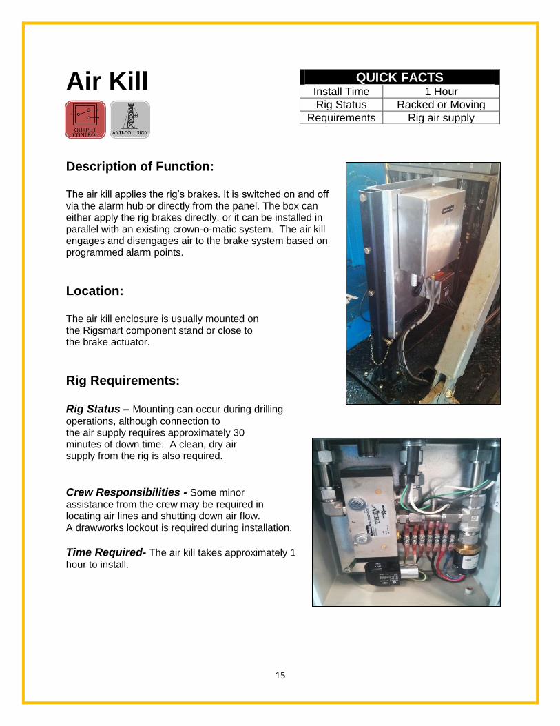
Description of Function: The air kill applies the rig’s brakes. It is switched on and off via the alarm hub or directly from the panel. The box can either apply the rig brakes directly, or it can be installed in parallel with an existing crown-o-matic system. The air kill engages and disengages air to the brake system based on programmed alarm points.
Location: The air kill enclosure is usually mounted on the Rigsmart component stand or close to the brake actuator.
Rig Requirements: Rig Status – Mounting can occur during drilling
operations, although connection to the air supply requires approximately 30 minutes of down time. A clean, dry air supply from the rig is also required.
Crew Responsibilities - Some minor
assistance from the crew may be required in locating air lines and shutting down air flow. A drawworks lockout is required during installation.
Time Required- The air kill takes approximately 1
hour to install.
QUICK FACTS Install Time 1 Hour
Rig Status Racked or Moving
Requirements Rig air supply

16
Rigsmart Systems, Inc. 4908 97 St. Edmonton, AB T6L 4B2 Ph: 780.438.9475 Email: [email protected]
Air Kill Data Sheet
Overview The Rigsmart Airkill contains classified electronic over pneumatic solenoids which are activated to apply a rig’s main brake or auxiliary brake. There are various internal configurations designed for different customer braking systems. Operating time 100% (continuous duty) Voltage type 12-24 VDC Operating temperature -40°C to +60°C Material - 16 gauge steel body and cover - Welded seams without knockouts or holes
- Seamless poured-in place gasket - Door includes a quarter turn slot for added safety Connection 12-24 VDC supplied by the Rigsmart system and a rig air connection. Mounting options Various brackets available to meet application requirements Hazardous locations Class 1 group A,B,C,D
Class 2 Group E,F,G
General purpose valave for hazardous locations, 644A Environmental Ingress Protection IP67 Application Drilling, Snubbing or Workover rigs
*Information subject to change without notice. Consult the
factory for the most current data and part numbers.*

17
BOP Ram Sensor
Description of Function:
The BOP Ram Sensors detect open and closed position of the BOP rams. The sensors come in sets of two (one for each ram side) and work in conjunction. The transducer is made up of a proximity sensor that can detect when a metal object is close to it or not. The panel identifies the ram (and which side) has been closed.
Location: The sensors are mounted on the end of the ram. When the ram is open, the end of the ram shaft is positioned ¼” away from the sensor’s pickup.
Rig Requirements: Rig Status - The monitored equipment needs to function
after installation, for testing purposes.
Crew Responsibilities - Some minor assistance from the
crew may be required in testing operations, and identifying a mounting location.
Time Required - Sensors can be installed
in approximately 1 hour, once the mounts are fabricated.
QUICK FACTS Install Time 30 Minutes
Rig Status Racked
Requirements BOP access and custom bracket

18
Rigsmart Systems, Inc. 4908 97 St. Edmonton, AB T6L 4B2 Ph: 780.438.9475 Email: [email protected]
BOP Ram Senor Data Sheet
Overview The Rigsmart BOP Ram Sensor is a proximity device which detects the presence of the BOP polish rod. Operating time 100% (continuous duty) Voltage type Powered by a 3.6 volt D cell lithium battery Operating temperature -40°C to +60°C Operating Frequency Range 900-928 MHz in North America 868-870 MHz in Europe Material Body material – Ultramid 8333G Hi-Polyamide 6 Seals – ROHS compliant silicon rubber, 60 durometer shore-A, compound # SIM40160 Connection No connection, component provides a wireless signal Mounting options Brackets fabricated for various BOP’s Hazardous locations Exia IIB T4 Intrinsically Safe per IEC CAN/CSA E60079-11:02 Environmental Ingress Protection IP67 Application Workover units
*Information subject to change without notice. Consult the
factory for the most current data and part numbers.*

19
LED Indicator
Description of Function: The LED Display is a visual indicator for the ram sensors. Each LED is paired to a specific set of rams, and will flash either red (for closed ram status) or green (for open), as indicated by the sensors.
Location: The sensors are magnetically mounted, and can be placed wherever the operator has a direct line of sight to the device.
Rig Requirements: Rig Status – N/A
Crew Responsibilities – N/A
Time Required – N/A
QUICK FACTS Install Time N/A
Rig Status N/A
Requirements N/A

20
Rigsmart Systems, Inc. 4908 97 St. Edmonton, AB T6L 4B2 Ph: 780.438.9475 Email: [email protected]
LED Indicator Data Sheet
Overview The Rigsmart LED indicator visually displays the BOP status. Operating time 100% (continuous duty) Voltage type Powered by a 3.6 volt D cell lithium battery Operating temperature -40°C to +60°C Operating Frequency Range 900-928 MHz in North America 868-870 MHz in Europe Material Body material – Ultramid 8333G Hi-Polyamide 6 Seals – ROHS compliant silicon rubber, 60 durometer shore-A, compound # SIM40160 Connection No connection, component provides a wireless signal Mounting options Magnetic mounting bracket Hazardous locations Exia IIB T4 Intrinsically Safe per IEC CAN/CSA E60079-11:02 Environmental Ingress Protection IP67 Application Workover units
*Information subject to change without notice. Consult the factory
for the most current data and part numbers.*

21
Pressure Sensor
Description of Function: A wireless component which measures fluid or gas pressure directly off of pipes and transmits the reading back to the main display panel. Pressure sensors are supplied in a variety of ranges from 100 PSI – 15,000 PSI.
Location: Can be connected to any ½” NPT port or configured to any custom connection. A Hammer Union or ½” port is required.
Rig Requirements: Rig Status – Racked
Crew Responsibilities – Provide assistance with installation location. Time Required – 30 minutes
QUICK FACTS Install Time 30 minutes
Rig Status Racked
Requirements Hammer Union or Nipple

22
Pressure Sensor Data Sheet
Overview A wireless component which measures fluid pressure directly off of pipes and transmits the reading back to the main display panel. They are available in 100, 3,000, 5,000, 10,000, and 15,000 PSI models. Operating time 100% (continuous duty) Voltage type Powered by a 3.6 volt D cell lithium battery Operating temperature -40°C to +60°C Operating Frequency Range 900-928 MHz in North America 868-870 MHz in Europe Material Body material – Ultramid 8333G Hi-Polyamide 6 Seals – ROHS compliant silicon rubber, 60 durometer shore-A, compound # SIM40160 Connection No connection, component provides a wireless signal Mounting options 1/4” NPT, 1/2” NPT, hammer union Hazardous locations Exia IIB T4 Intrinsically Safe per IEC CAN/CSA E60079-11:02 Environmental Ingress Protection IP67 Application Drilling rigs, Workover rigs, and Snubbing units
*Information subject to change without notice. Consult the
factory for the most current data and part numbers.*
Rigsmart Systems, Inc. 4908 97 St. Edmonton, AB T6L 4B2 Ph: 780.438.9475 Email: [email protected]

23
Line Rider
Description of Function: A wireless weight indicator that measures line tension. The load indicator remains accurate and repeatable over time and through temperature extremes. The indicator does not need to be removed during a slip and cut and does not need to be recalibrated afterwards.
Location: Mounted on the deadline of the blocks above the deadman.
Rig Requirements: Rig Status – Installation can take place at any time. Crew Responsibilities – Approval of the mounting location Time Required – 2 hours
QUICK FACTS Install Time 2 hours
Rig Status Racked, Moving or Operating
Requirements None

24
Line Rider Data Sheet Overview
A wireless component that detects how much weight is suspended by the blocks. It remains accurate over time and through temperature extremes. Through its design, it does not need to be removed during a slip and cut and does not need to be recalibrated afterwards, as long as the same size line is used. Operating time 100% (continuous duty) Voltage type Powered by a 3.6 volt D cell lithium battery Operating temperature -40°C to +60°C Operating Frequency Range 900-928 MHz in North America 868-870 MHz in Europe Material Body material – Ultramid 8333G Hi-Polyamide 6 Seals – ROHS compliant silicon rubber, 60 durometer shore-A, compound # SIM40160
Connection No connection, component provides a wireless signal Mounting options Fitted to drill line size Hazardous locations Exia IIB T4 Intrinsically Safe per IEC CAN/CSA E60079-11:02 Environmental Ingress Protection IP67 Application Drilling or Workover rigs
*Information subject to change without notice. Consult the
factory for the most current data and part numbers.*
Rigsmart Systems, Inc. 4908 97 St. Edmonton, AB T6L 4B2 Ph: 780.438.9475 Email: [email protected]
25
Emergency Shut Down
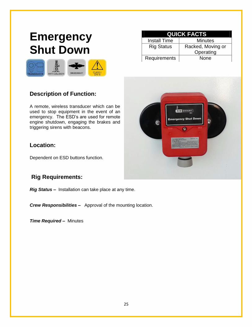
Description of Function: A remote, wireless transducer which can be used to stop equipment in the event of an emergency. The ESD’s are used for remote engine shutdown, engaging the brakes and triggering sirens with beacons.
Location: Dependent on ESD buttons function.
Rig Requirements: Rig Status – Installation can take place at any time. Crew Responsibilities – Approval of the mounting location. Time Required – Minutes
QUICK FACTS Install Time Minutes
Rig Status Racked, Moving or Operating
Requirements None
26
Emergency Shut Down Data Sheet
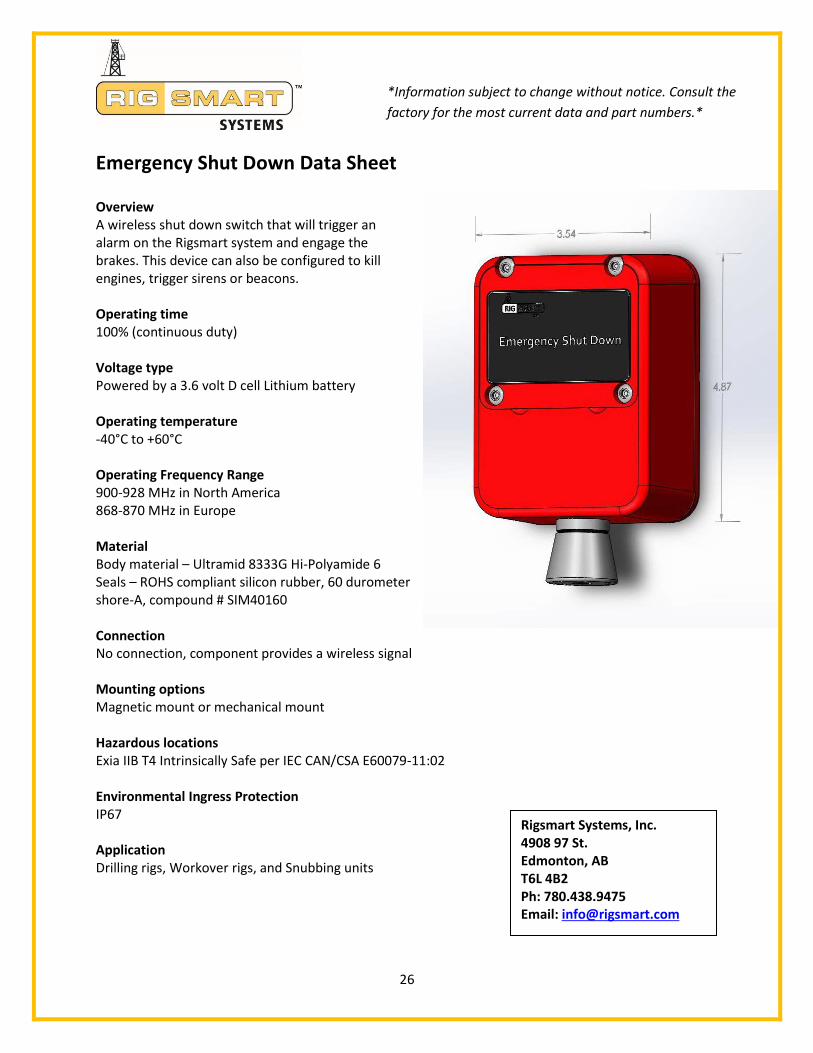
Overview A wireless shut down switch that will trigger an alarm on the Rigsmart system and engage the brakes. This device can also be configured to kill engines, trigger sirens or beacons. Operating time 100% (continuous duty) Voltage type Powered by a 3.6 volt D cell Lithium battery Operating temperature -40°C to +60°C Operating Frequency Range 900-928 MHz in North America 868-870 MHz in Europe Material Body material – Ultramid 8333G Hi-Polyamide 6 Seals – ROHS compliant silicon rubber, 60 durometer shore-A, compound # SIM40160 Connection No connection, component provides a wireless signal Mounting options Magnetic mount or mechanical mount Hazardous locations Exia IIB T4 Intrinsically Safe per IEC CAN/CSA E60079-11:02 Environmental Ingress Protection IP67 Application Drilling rigs, Workover rigs, and Snubbing units
*Information subject to change without notice. Consult the
factory for the most current data and part numbers.*
Rigsmart Systems, Inc. 4908 97 St. Edmonton, AB T6L 4B2 Ph: 780.438.9475 Email: [email protected]

27
Commissioning,
Testing and
Training
Description of Function: Commissioning, testing and training are considered the most important part of the installation procedure. Calibrations are vital to optimal system performance. It is Rigsmart’s goal is to train operators and crews to use and maintain their own systems safely and effectively. Collision and zone management limits are set and adjusted with the rig crew’s input and cooperation. Post installation service is available 24/7 and technicians are always standing by with answers to questions and information that can be emailed about the
specific system in question.
Rig Requirements: Rig Status – The rig must be operational and able to provide a full function test. Crew Responsibilities – A driller or Rig Manager is required to operate the different functions of the rig such as raising or lowing the blocks, opening and closing the rams, and lifting known weight. Time Required – Testing each component can take up to 30 minutes per component. Commissioning the full system may take up to 4 hours, depending on the situation. Training the Rig Manager and crew may take anywhere between one hour of instruction to a day of operational training as the rig performs routine tasks.
QUICK FACTS Install Time Various
Rig Status Operating
Requirements Driller, Rig Manager and any personnel requiring training