work - lmsc, lan/man standards committee
TRANSCRIPT

IEEE 802.16.1-00/01r4, September 2000
1234567891011121314151617181920212223242526272829303132333435363738394041424344454647484950515253545556575859606162636465
and Wireless Accessnal pro-
Information Technology-
Telecommunications and Information Exchange Between Systems –
LAN/MAN Specific Requirements –
Air Interface for Fixed Broadband Wireless Access Systems
Sponsor
LAN MAN Standards Committee
of the IEEE Computer Society
Abstract: This document is FOR COMMENT as a potential DRAFT standard for medium-access physical layer components that meet the functional requirements of a point-to-multipoint Broadband(BWA) system as defined by the IEEE 802.16 Working Group. Detailed logical, electrical, and sigcessing specifications are presented that enable the production of interoperable equipment.
Keywords: wireless metropolitan area network (WirelessMANTM) standards, fixed broadbandwireless access networks, millimeter waves
1
1. The Institute of Electrical and Electronics Engineers, Inc.3 Park Avenue, New York, NY 10016-5997, USAAll rights reserved. Published August 2000. Printed in the United States of America.Print: ISBN 0-7381-xxxx-x SHxxxxxPDF: ISBN 0-7381-xxxx-x SSxxxxxNo part of this publication may be reproduced in any form, in an electronic retrieval system or otherwise, without the prior written permission of the publisher.
This is an unapproved Task Group document being circulated for comment. i

IEEE 802.16.1-00/01r4, September 2000
1234567891011121314151617181920212223242526272829303132333435363738394041424344454647484950515253545556575859606162636465
IEEE Standards documents are developed within the IEEE Societies and the Standards Coordinating Com-mittees of the IEEE Standards Association (IEEE-SA) Standards Board. Members of the committees servevoluntarily and without compensation. They are not necessarily members of the Institute. The standardsdeveloped within IEEE represent a consensus of the broad expertise on the subject within the Institute aswell as those activities outside of IEEE that have expressed an interest in participating in the development ofthe standard.
Use of an IEEE Standard is wholly voluntary. The existence of an IEEE Standard does not imply that thereare no other ways to produce, test, measure, purchase, market, or provide other goods and services related tothe scope of the IEEE Standard. Furthermore, the viewpoint expressed at the time a standard is approved andissued is subject to change brought about through developments in the state of the art and commentsreceived from users of the standard. Every IEEE Standard is subjected to review at least every five years forrevision or reaffirmation. When a document is more than five years old and has not been reaffirmed, it is rea-sonable to conclude that its contents, although still of some value, do not wholly reflect the present state ofthe art. Users are cautioned to check to determine that they have the latest edition of any IEEE Standard.
Comments for revision of IEEE Standards are welcome from any interested party, regardless of membershipaffiliation with IEEE. Suggestions for changes in documents should be in the form of a proposed change oftext, together with appropriate supporting comments.
Interpretations: Occasionally questions may arise regarding the meaning of portions of standards as theyrelate to specific applications. When the need for interpretations is brought to the attention of IEEE, theInstitute will initiate action to prepare appropriate responses. Since IEEE Standards represent a consensus ofall concerned interests, it is important to ensure that any interpretation has also received the concurrence of abalance of interests. For this reason, IEEE and the members of its societies and Standards CoordinatingCommittees are not able to provide an instant response to interpretation requests except in those cases wherethe matter has previously received formal consideration.
Comments on standards and requests for interpretations should be addressed to:
Secretary, IEEE-SA Standards Board445 Hoes LaneP.O. Box 1331Piscataway, NJ 08855-1331USA
Note: Attention is called to the possibility that implementation of this standard may require use of subjectmatter covered by patent rights. By publication of this standard, no position is taken with respect to the exist-ence or validity of any patent rights in connection therewith. The IEEE shall not be responsible for identify-ing patents for which a license may be required by an IEEE standard or for conducting inquiries into thelegal validity or scope of those patents that are brought to its attention
IEEE is the sole entity that may authorize the use of certification marks, trademarks, or other designations toindicate compliance with the materials set forth herein.
Authorization to photocopy portions of any individual standard for internal or personal use is granted by theInstitute of Electrical and Electronics Engineers, Inc., provided that the appropriate fee is paid to CopyrightClearance Center. To arrange for payment of licensing fee, please contact Copyright Clearance Center, Cus-tomer Service, 222 Rosewood Drive, Danvers, MA 01923 USA; (978) 750-8400. Permission to photocopyportions of any individual standard for educational classroom use can also be obtained through the Copy-right Clearance Center.
This is an unapproved Task Group document being circulated for comment. ii

IEEE 802.16.1-00/01r4, September 2000
1234567891011121314151617181920212223242526272829303132333435363738394041424344454647484950515253545556575859606162636465
Introduction
(This introduction is not part of IEEE Std 802.16.1, IEEE Standard for Broadband Wireless Access.)
This document defines services and protocol elements that permit the exchange of management informationbetween stations attached to IEEE 802 local and metropolitan area networks. The standard includes thespecification of managed objects that permit the operation of the protocol elements to be remotely managed.
Participants
At the time the draft of this standard was sent to sponsor ballot, the IEEE 802.16 Working Group on Broad-band Wireless Access had the following members:
Roger B. Marks, ChairLouis Olsen, Vice ChairJ. Scott Marin, SecretaryJames F. Mollenauer and Brian Petry, Chief Technical Editors, Standard 802.16.1Glen E. Sater, 802.16.1 MAC EditorJeffrey R. Foerster, 802.16.1 PHY EditorCarl Eklund, 802.16.1 MAC Task Group ChairJay Klein, 802.16.1 PHY Task Group Chair
<list of voting members>
This is an unapproved Task Group document being circulated for comment. iii

IEEE 802.16.1-00/01r4, September 2000
1234567891011121314151617181920212223242526272829303132333435363738394041424344454647484950515253545556575859606162636465
When the IEEE-SA Standards Board approved this standard on xxxxx, it had the following membership
Donald N. Heirman, Chair
James T. Carlo, Vice Chair
Judith Gorman, Secretary
Satish K. AggarwalMark D. BowmanGary R. EngmannHarold E. EpsteinH. Landis FloydJay Forster*Howard M. FrazierRuben D. GarzonJames H. GurneyRichard J. HollemanLowell G. JohnsonRobert J. KennellyJoseph L. Koepfinger*Peter H. LipsL. Bruce McClungDaleep C. MohlaJames W. MooreRobert F. MunznerRonald C. PetersenGerald H. PetersonJohn B. PoseyGary S. RobinsonAkio TojoDonald W. Zipse
*Member Emeritus
Also included is the following nonvoting IEEE-SA Standards Board liaison:
Alan Cookson, NIST RepresentativeDonald R. Volzka, TAB Representative
Gregory KohnIEEE Standards Project Editor
This is an unapproved Task Group document being circulated for comment. iv

IEEE 802.16.1-00/01r4, September 2000
Table of Contents
1 Overview.............................................................................................................................................. 1
1.1 Normative references ................................................................................................................... 11.2 Definitions.................................................................................................................................... 31.3 Terminology................................................................................................................................. 41.4 Acronyms and abbreviations ....................................................................................................... 51.5 Scope............................................................................................................................................ 61.6 Supported Services ...................................................................................................................... 71.7 Target Applications...................................................................................................................... 8
1.7.1 Bearer Services ................................................................................................................ 91.8 System Model ............................................................................................................................ 11
1.8.1 System reference points ................................................................................................. 121.8.2 Topology ........................................................................................................................ 12
1.9 Protocols .................................................................................................................................... 131.10 Performance and Capacity ......................................................................................................... 13
1.10.1 Scalability ...................................................................................................................... 131.10.2 Delivered Bandwidth ..................................................................................................... 131.10.3 Flexible Asymmetry ...................................................................................................... 131.10.4 Radio Link Availability ................................................................................................. 141.10.5 Error Performance.......................................................................................................... 141.10.6 Delay .............................................................................................................................. 141.10.7 Capacity Issues .............................................................................................................. 15
1.11 Class of Service and Quality of Service .................................................................................... 151.11.1 Bearer Service QoS Mappings....................................................................................... 16
1.12 Management............................................................................................................................... 171.12.1 Service Level Agreements ............................................................................................. 171.12.2 Accounting and Auditing............................................................................................... 17
1.13 Security ...................................................................................................................................... 171.13.1 Authentication................................................................................................................ 171.13.2 Authorization ................................................................................................................. 171.13.3 Privacy ........................................................................................................................... 18
1.14 IEEE 802 Architectural Conformance ..................................................................................... 181.15 MAC Services to the convergence sublayers (CL).................................................................... 18
1.15.1 Primitives ....................................................................................................................... 19
2 Medium Access Control .................................................................................................................... 27
2.1 Connections and Service Flows ................................................................................................. 282.1.1 Definitions ..................................................................................................................... 282.1.2 Addressing and Connection Identifiers.......................................................................... 30
2.2 Parameters and Constants .......................................................................................................... 312.3 Encodings for Configuration and MAC-Layer Messaging........................................................ 34
2.3.1 Configuration File and Registration Settings................................................................. 342.3.2 Configuration-File-Specific Settings ............................................................................. 372.3.3 Registration-Request/Response-Specific Encodings ..................................................... 392.3.4 Dynamic-Service-Message-Specific Encodings............................................................ 412.3.5 Quality-of-Service-Related Encodings .......................................................................... 422.3.8 Privacy Configuration Settings Option.......................................................................... 522.3.9 Confirmation Code ........................................................................................................ 522.3.10 Convergence Sub-Layer Parameter Encodings ............................................................. 53
2.4 Configuration File...................................................................................................................... 53
v

2.4.1 SS IP Addressing ........................................................................................................... 532.4.2 SS Configuration............................................................................................................ 542.4.3 Configuration Verification............................................................................................. 57
2.5 Message Formats ....................................................................................................................... 582.5.1 Convergence Sub-layer PDU Formats........................................................................... 642.5.2 MAC Management Messages........................................................................................ 642.5.3 Downlink MAP (DL-MAP) Message............................................................................ 772.5.4 Uplink MAP (UL-MAP) Message................................................................................. 802.5.5 Ranging Request (RNG-REQ) Message........................................................................ 822.5.6 Ranging Response (RNG-RSP) Message ...................................................................... 842.5.7 Registration Request (REG-REQ) Message .................................................................. 892.5.8 Registration Response (REG-RSP) Message ................................................................ 902.5.9 Registration Acknowledge (REG-ACK) Message ........................................................ 932.5.10 Privacy Key Management — Request (PKM-REQ) Message ...................................... 942.5.11 Privacy Key Management — Response (PKM-RSP) Message..................................... 952.5.12 Dynamic Service Addition — Request (DSA-REQ) Message...................................... 962.5.13 Dynamic Service Addition — Response (DSA-RSP) Message .................................... 972.5.14 Dynamic Service Addition — Acknowledge (DSA-ACK) Message ............................ 992.5.15 Dynamic Service Change — Request (DSC-REQ) Message ...................................... 1012.5.16 Dynamic Service Change — Response (DSC-RSP) Message .................................... 1022.5.17 Dynamic Service Change — Acknowledge (DSC-ACK) Message ............................ 1032.5.18 Dynamic Service Deletion — Request (DSD-REQ) Message .................................... 1052.5.19 Dynamic Service Deletion — Request (DSD-RSP) Message ..................................... 1062.5.20 Multicast Polling Assignment Request (MCA-REQ) Message................................... 1062.5.21 Multicast Polling Assignment Response (MCA-RSP) Message ................................. 1082.5.22 ARQ-ACK Message .................................................................................................... 1092.5.23 Downlink Burst Type Change Request (DBTC-REQ) Message................................. 109
2.6 Duplexing Techniques, Framing, and Scheduling Intervals .................................................... 1102.6.1 Duplexing Techniques ................................................................................................. 1102.6.2 PHY Burst Mode Support............................................................................................ 1122.6.3 PHY Continuous Mode Support .................................................................................. 1132.6.4 PHY Burst Mode Support............................................................................................ 1132.6.5 Uplink Burst Subframe Structure ................................................................................ 1162.6.6 Continuous Downstream and Upstream Structure....................................................... 1172.6.7 Upstream Map.............................................................................................................. 1172.6.8 MAP Relevance and Synchronization ......................................................................... 120
2.7 Contention Resolution ............................................................................................................. 1222.7.1 Transmit Opportunities ................................................................................................ 123
2.8 Fragmentation .......................................................................................................................... 1242.9 Upstream Service ..................................................................................................................... 124
2.9.1 Unsolicited Grant Service ............................................................................................ 1252.9.2 Real-Time Polling Service........................................................................................... 1262.9.3 Unsolicited Grant Service with Activity Detection ..................................................... 1262.9.4 Non-Real-Time Polling Service................................................................................... 1272.9.5 Best Effort Service....................................................................................................... 127
2.10 Bandwidth Allocation and Request Mechanisms .................................................................... 1272.10.1 Requests ....................................................................................................................... 1272.10.2 Polling .......................................................................................................................... 1312.10.3 Poll-Me Bit .................................................................................................................. 135
2.11 Network Entry and Initialization ............................................................................................. 1352.11.1 Scanning and Synchronization to Downstream........................................................... 1372.11.2 Scanning and Synchronization to Downstream........................................................... 1382.11.3 Obtain Downlink Parameters....................................................................................... 1382.11.4 Obtain Upstream Parameters ....................................................................................... 138

IEEE 802.16.1-00/01r4, September 2000
2.11.5 message Flows During Scanning and Upstream Parameter Acquisition..................... 1412.11.6 Initial Ranging and Automatic Adjustments ............................................................... 1422.11.7 Ranging Parameter Adjustment ................................................................................... 1482.11.8 Initial Connection Establishment................................................................................. 1482.11.9 Transfer Operational Parameters ................................................................................. 149
2.12 Ranging .................................................................................................................................... 1552.12.1 Burst Mode Downstream Modulation/FEC Management ........................................... 157
2.13 Quality of Service .................................................................................................................... 1582.13.1 Theory of Operation..................................................................................................... 1592.13.2 Service Flows............................................................................................................... 1592.13.3 Object Model ............................................................................................................... 1622.13.4 Service Classes ............................................................................................................ 1632.13.5 Authorization ............................................................................................................... 1642.13.6 Types of Service Flows................................................................................................ 1652.13.7 General Operation........................................................................................................ 1662.13.8 Dynamic Service.......................................................................................................... 170
2.14 Authentication and Privacy...................................................................................................... 2062.14.1 Privacy Overview ........................................................................................................ 2062.14.2 Architectural Overview................................................................................................ 2072.14.3 Operational Overview.................................................................................................. 209
2.15 MAC Frame Formats ............................................................................................................... 2102.15.1 Fragmentation and Encryption..................................................................................... 211
2.16 Privacy Key Management (PKM) Protocol............................................................................. 2112.16.1 State Models ................................................................................................................ 2112.16.2 Key Management Message Formats ............................................................................ 229
2.17 Dynamic SA Mapping ............................................................................................................. 2582.17.1 Introduction.................................................................................................................. 258
2.18 Key Usage................................................................................................................................ 2582.18.1 BS................................................................................................................................. 2582.18.2 SS ................................................................................................................................. 260
2.19 Cryptographic Methods ........................................................................................................... 2612.19.1 Packet Data Encryption ............................................................................................... 2612.19.2 Encryption of TEK....................................................................................................... 2612.19.3 HMAC-Digest Algorithm ............................................................................................ 2622.19.4 Derivation of TEKs, KEKs and Message Authentication Keys .................................. 2622.19.5 Public-Key Encryption of Authorization Key ............................................................. 2632.19.6 Digital Signatures ........................................................................................................ 2632.19.7 Supporting Alternative Algorithms ............................................................................. 263
2.20 TFTP Configuration File Extensions ....................................................................................... 2632.20.1 Privacy Configuration Setting Encodings.................................................................... 263
3 Physical Layer.................................................................................................................................. 269
3.1 Overview................................................................................................................................. 2693.1.1 Multiplexing and Multiple Access Technique............................................................. 2693.1.2 Duplexing Technique................................................................................................... 2693.1.3 Physical Media Dependent (PMD) Sublayers ............................................................. 269
3.2 Downstream Physical Layer .................................................................................................... 2703.2.1 Mode A: Continuous Downstream Transmission........................................................ 2713.2.2 Mode B: Burst Downstream Transmission.................................................................. 279
3.3 Upstream Physical Layer ......................................................................................................... 2973.3.1 Upstream Channel and Burst Descriptions.................................................................. 2973.3.2 Upstream Transmission Convergence (TC) Sublayer ................................................. 2973.3.3 Upstream Physical Media Dependent (PMD) sublayer ............................................... 298
vii

3.4 Baud Rates and Channel Bandwidths...................................................................................... 3113.5 Radio Sub-system Control ....................................................................................................... 313
3.5.1 Synchronization Technique (Frame and Slot) ............................................................ 3133.5.2 Frequency Control ...................................................................................................... 3133.5.3 Power Control ............................................................................................................. 313
3.6 Minimum Performance ............................................................................................................ 3143.6.1 Reference test planes ................................................................................................... 3173.6.2 Propagation Conditions................................................................................................ 3173.6.3 Transmitter characteristics ........................................................................................... 3173.6.4 Receiver Characteristic ............................................................................................... 3193.6.5 Transmitter / Receiver Performance ............................................................................ 319
4 Bibliography .................................................................................................................................... 321

IEEE 802.16.1-00/01r4, September 2000
1234567891011121314151617181920212223242526272829303132333435363738394041424344454647484950515253545556575859606162636465
List of Figures
Relationship between 802.16.1 and other Protocol Standards (the numbers in the figure re-fer to IEEE standard numbers 7A Multi-Tier Perspective of Wireless Transmission and Distribution Systems 9Protocol layers 10System Reference Points 12802.16.1 protocol layering, showing service access point. 19Use of primitives to request service of MAC layer and generate response. 20Binary Configuration File Format 55Create TLV Entries for Parameters Required by the SS 56Add SS MIC 56Add BS MIC 56Add End of Data Marker 57MAC PDU Formats 59Generic MAC Header Format (Uplink) 60Generic MAC Header Format (Downlink) 61Bandwidth Request Header Format 61MAC PDU Concatenation showing example CIDs 64Convergence Sub-layer PDU Format 64MAC Management Message Format 65Uplink Channel Descriptor (UCD) Message Format 67Top-Level Encoding for a Burst Descriptor 70Downlink Channel Descriptor (DCD) Message Format 73Top-Level Encoding for a Downlink Burst Descriptor 75Downlink MAP Message Format 77PHY Synchronization Field (PHY Type = {0,1,3}) 78PHY Synchronization Field (PHY Type = 5) 78Downlink TDM MAP Message Element Format 79Downlink TDMA MAP Message Element Format 79Uplink MAP Message Format 80UL-MAP Information Element 82RNG-REQ Message Format 82RNG-RSP Message Format 85Generalized Decision Feedback Equalization Coefficients 88Generalized Equalizer Tap Location Definition 88REG-REQ Message Format 89REG-RSP Message Format 91REG-ACK Message Format 93PKM-REQ Message Format 94PKM-RSP Message Format 96DSA-REQ Message Format 96DSA-RSP Message Format 98DSA-ACK Message Format 100DSC-REQ Message Format 101DSC-RSP Message Format 102DSC-ACK Message Format 104DSD-REQ Message Format 105
This is an unapproved Task Group document being circulated for comment. xxi

IEEE 802.16.1-00/01r4, September 2000
1234567891011121314151617181920212223242526272829303132333435363738394041424344454647484950515253545556575859606162636465
DSD-RSP Message Format 106Multicast Polling Assignment Request (MCA-REQ) Message Format 107Multicast Polling Assignment Response (MCA-RSP) Message Format 108Downlink Burst Type Change Request (DMC-REQ) Message Format 109Example of FSDD Bandwidth Allocation 111 TDD Frame Structure 111Burst Downstream FDD/FSDD Mapping 112TDD and Burst FDD/TDM Downstream Subframe Structure 114Burst FDD/TDMA Downstream Subframe Structure 114Uplink Subframe Structure 116Continuous Downstream FDD Mapping 117BS System and Mini-slot Clocks 119Maximum Time Relevance of PHY and MAC Control Information (TDD) 121Maximum Time Relevance of PHY and MAC Control Information (FDD) 121Minimum Time Relevance of PHY and MAC Control Information (FDD) 121Minimum Time Relevance of PHY and MAC Control Information (TDD) 122Time Relevance of Upstream MAP Information (Continuous FDD) 122SS GPC mode flowchart 129SS GPT mode flowchart 130Unicast Polling 132Multicast and Broadcast Polling 134Poll Me Bit Usage 135 SS Initialization Overview 137 Obtaining Upstream Parameters 140Initial Ranging - SS (continued) 146Initial Ranging - BS 147Registration — SS 150Wait for registration response — SS 151Registration — BS 153Registration Acknowledgment— BS 154Periodic Ranging - BS 156Periodic Ranging - SS 157Modulation Threshold Usage 158Provisioned Authorization Model “Envelopes” 161Dynamic Authorization Model “Envelopes” 162Theory of Operation Object Model 163Registration Message Flow 167Dynamic Service Addition Message Flow — SS Initiated 169Dynamic Service Addition Message Flow — BS Initiated 169Dynamic Service Flow Overview 170Dynamic Service Flow State Transition Diagram 173DSA - Locally Initiated Transaction State Transition Diagram 174DSA - Remotely Initiated Transaction State Transition Diagram 175DSC - Locally Initiated Transaction State Transition Diagram 176DSC - Remotely Initiated Transaction State Transition Diagram 177DSD - Locally Initiated Transaction State Transition Diagram 178
This is an unapproved Task Group document being circulated for comment. xxii

IEEE 802.16.1-00/01r4, September 2000
1234567891011121314151617181920212223242526272829303132333435363738394041424344454647484950515253545556575859606162636465
Dynamic Deletion (DSD) - Remotely Initiated Transaction State Transition Diagram 179DSA - Locally Initiated Transaction Begin State Flow Diagram 182DSA - Locally Initiated Transaction DSA-RSP Pending State Flow Diagram 183DSA - Locally Initiated Transaction Holding State Flow Diagram 184DSA - Locally Initiated Transaction Retries Exhausted State Flow Diagram 185DSA - Locally Initiated Transaction Deleting Service Flow State Flow Diagram 186DSA - Remotely Initiated Transaction Begin State Flow Diagram 187DSA - Remotely Initiated Transaction DSA-ACK Pending State Flow Diagram 188DSA - Remotely Initiated Transaction Holding Down State Flow Diagram 189DSA - Remotely Initiated Transaction Deleting Service State Flow Diagram 190DSC - Locally Initiated Transaction Begin State Flow Diagram 193DSC - Locally Initiated Transaction DSC-RSP Pending State Flow Diagram 194DSC - Locally Initiated Transaction Holding Down State Flow Diagram 195DSC - Locally Initiated Transaction Retries Exhausted State Flow Diagram 196DSC - Locally Initiated Transaction Deleting Service Flow State Flow Diagram 197DSC - Remotely Initiated Transaction Begin State Flow Diagram 198DSC - Remotely Initiated Transaction DSC-ACK Pending State Flow Diagram 199DSC - Remotely Initiated Transaction Holding Down State Flow Diagram 200DSC - Remotely Initiated Transaction Deleting Service Flow State Flow Diagram 201DSD - Locally Initiated Transaction Begin State Flow Diagram 203DSD - Locally Initiated Transaction DSD-RSP Pending State Flow Diagram 204DSD - Locally Initiated Transaction Holding Down State Flow Diagram 205DSD - Remotely Initiated Transaction Begin State Flow Diagram 206MAC PDU Encryption 210Authorization State Machine Flow Diagram 215TEK State Machine Flow Diagram 223Format of the Convergence Layer Packet 271 Conceptual Block diagram of the Mode A Downstream Physical Layer 272Randomizer logic diagram 273 Framing structure based on transmission convergence sublayer. 274 Conceptual diagram of the convolutional interleaver and de-interleaver. 275 QPSK symbol mapping 276 Example implementation of the byte to m-tuple conversion and the differential encoding of the two MSBs. 27716-QAM Constellation Diagram 27864-QAM Constellation Diagram 279 Format of the Convergence Layer Packet 280Conceptual Block diagram of the Mode B Downstream Physical Layer 281Randomizer logic diagram. 282Two-dimensional product code matrix. 284Example Encoder for a (16,11) Extended Hamming Code 285Structure of Shortened 2 D Block 287 QPSK Constellation 292 16-QAM Constellation 292 64-QAM Constellation 294 Format of the Convergence Layer Packet 298
This is an unapproved Task Group document being circulated for comment. xxiii

IEEE 802.16.1-00/01r4, September 2000
1234567891011121314151617181920212223242526272829303132333435363738394041424344454647484950515253545556575859606162636465
Conceptual Block diagram of the 802.16 Burst Transmission Upstream Physical Layer 298Two-dimensional product code matrix. 301Example Encoder for a (16,11) Extended Hamming Code 302Structure of Shortened 2 D Block 304 QPSK constellation mapping 306 16-QAM Constellation 307 64-QAM Constellation 308
This is an unapproved Task Group document being circulated for comment. xxiv

IEEE 802.16.1-00/01r4, September 2000
1234567891011121314151617181920212223242526272829303132333435363738394041424344454647484950515253545556575859606162636465
List of Tables
Connection Identifiers 31Parameters and Constants 32Values Used in REG-REQ and REG-RSP Messages 45Values Used In Dynamic Service Messages. 45MAC Header Fields 62MAC Management Messages 65Uplink Physical Channel Attributes 68Uplink Map Information Elements 69Uplink Physical Layer Burst Profile Parameters 71Downlink Physical Channel Attributes 74Mapping of Burst Type to Downlink Interval Usage Code 74Downlink Physical Layer Burst Profile Parameters 76Uplink MAP Information Elements 83Ranging Request Message Encodings 85Ranging Response Message Encodings 87Multicast Assigment Request Message Encodings 108 Allowable frame times 115Downstream Physical Layer 116Fragmentation Rules 124Scheduling Services and Usage Rules 125Sample Upstream MAP with Multicast and Broadcast IE 133message Flows During Scanning and Upstream Parameter Acquisition 141Ranging and Automatic Adjustments Procedure 143Establishing IP Connectivity 148Establishing Time of Day 149Downlink Modulation/FEC Change Initiated from SS 158TFTP File Contents 167Registration Response Contents 168Registration Request Contents 168Dynamic Service Addition Initiated from SS 179Dynamic Service Addition Initiated from BS 181SS-Initiated DSC 191BS-Initiated DSC 192Dynamic Service Deletion Initiated from SS 202Dynamic Service Deletion Initiated from BS 202 Authorization FSM State Transition Matrix 216TEK FSM State Transition Matrix 224Privacy Key Management MAC Messages 229Privacy Key Management Message Codes 230Authorization Request Attributes 232Key Request Attributes 233Authorization Reply Attributes 233Auth Rej Attributes 233Key Reply Attributes 234Authorization Invalid Attributes 235Key Reject Attributes 235
This is an unapproved Task Group document being circulated for comment. xxv

IEEE 802.16.1-00/01r4, September 2000
1234567891011121314151617181920212223242526272829303132333435363738394041424344454647484950515253545556575859606162636465
TEK Invalid Attributes 236Authentication Information Attributes 236SA Map Request Attributes 237SA Map Reply Attributes 237SA MAP Reject Attributes 238PKM Attribute Types 239Attribute Value Data Types 240TEK-Parameters Sub-Attributes 249Error-Code Attribute Code Values 250Security-Capabilities Sub-Attributes 253Data Encryption Algorithm Identifiers 254Data Authentication Algorithm Identifiers 254Cryptographic-Suite Attribute Values 254Version Attribute Values 255SA-Descriptor Sub-Attributes 256SA-Type Attribute Values 256SA-Query-Type Attribute Values 258Recommended Operational Ranges for Privacy Configuration Parameters 266Shortened Privacy Parameter Values for Protocol Testing 267Convolutional Code Puncture Patterns 276 Conversion of constellation of quadrant 1 to other quadrants of the constellation diagrams given in the following diagrams. 277FEC Code Types for Burst Downstream (Mode B) 282The Parameters of the Inner Codes for the Block Convolutional Code 283Hamming Code Generator Polynomials 284Original Data for Encoding 286Encoded Block 286Required Block Codes for the BTC Option for the Downlink Channel 288 288 Burst Preamble Types 289 Burst Preamble 1 290Burst Preamble 2 291 QPSK Bits to Symbol Mapping 292 16-QAM Bits to Symbol Mapping 293 64-QAM Bits to Symbol Mapping 294Summary of Mode B Downstream Physical Layer Parameters 297FEC Code Types for the Upstream Channel 299The Parameters of the Inner Codes for the Block Convolutional Code 300Hamming Code Generator Polynomials 301Original Data for Encoding 302Encoded Block 303Required Block Codes for the BTC Option for the Uplink Channel 304QPSK Bits to Symbol Mapping 306 16-QAM Bits to Symbol Mapping 30764-QAM Bits to Symbol Mapping 308Summary of Upstream Physical Layer Parameters 311
This is an unapproved Task Group document being circulated for comment. xxvi

IEEE 802.16.1-00/01r4, September 2000
1234567891011121314151617181920212223242526272829303132333435363738394041424344454647484950515253545556575859606162636465
Recommended Baud rates for a roll-off factor of 0.15 312Recommended Baud rates for a roll-off factor of 0.25 312Recommended Baud rates for a roll-off factor of 0.35 313 PHY Layer Requirements 316 Propagation Models 317 Maximum BS Transmitter Power 318 CPE Power Control Levels 318Emissions Spectrum 318
This is an unapproved Task Group document being circulated for comment. xxvii

IEEE 802.16.1-00/01r4, September 2000
1234567891011121314151617181920212223242526272829303132333435363738394041424344454647484950515253545556575859606162636465
1 Overview
This standard includes specifications for the air interface, including the physical layer and medium accesscontrol layer, of fixed point-to-multipoint broadband wireless access systems providing multiple servicesoperating in the vicinity of 30 GHz. It is broadly applicable to systems operating between 10 and 66 GHz.
1.1 Normative references
This standard shall be used in conjunction with the following publications.
[DOCSIS] Data-Over-Cable Service Interface Specifications, "Radio Frequency Interface Specification",SP-RFIv1.1-I03-991103.
[EN 300 421] ETSI EN 300 421 V1.1.2 (1997-08), "Digital Video Broadcasting (DVB); Framing structure,channel coding and modulation for 11/112 GHz satellite services".
[EN 301 199] ETSI EN 301 199 v1.2.1 (1999-06), "Digital Video Broadcasting (DVB); Interaction channelfor Local Multi-point Distribution Systems (LMDS)".
[EN 301 210] ETSI EN 301 210 V1.1.1 (1999-03), "Digital Video Broadcasting (DVB); Framing structure,channel coding and modulation for Digital Satellite News Gathering (DSNG) and other contribution applica-tions by satellite".
[F.BWA] ITU-R 9B/134-E, JRG 8A-9B, New Recommendation ITU-R F.BWA, "Radio Transmission Sys-tems for Fixed Broadband Wireless Access (BWA) Based on Cable Modem Standards (Annex B of ITU-TRec. J.112)".
[FIPS-46-2]Federal Information Processing Standard Publications 46-2, “Data Encryption Standard (DES)”,December 30, 1993.
[FIPS-74]Federal Information Processing Standards Publication (FIPS PUB) 74, “Guidelines for Imple-menting and Using the Data Encryption Standard”, April 1981.
[FIPS-81]Federal Information Processing Standards Publication (FIPS PUB) 81, “DES Modes of Opera-tion”, December 1980.
[FIPS-140-1]Federal Information Processing Standards Publication (FIPS PUB) 140-1, “Security Require-ments for Cryptographic Modules”, April 1982.
[FIPS-180-1]Federal Information Processing Standards Publication (FIPS PUB) 180-1, “Secure Hash Stan-dard”, April 1995.
[FIPS-186]Federal Information Processing Standards Publication (FIPS PUB) 186, “Digital Signature Stan-dard”, 18 May 1994.
[G.114] ITU-T G.114 (05/00), Series G: “One-way transmission time.”
[I.210] ITU-T Recommendation I.210 (1993) - "ISDN Service Capabilities Principles of Telecommunica-tions Services Supported by an ISDN and the Means to Describe Them".
[IEEE802]IEEE Std 802-1990, “IEEE Standards for Local and Metropolitan Area Networks: Overview andArchitecture, December 1990”.
This is an unapproved Task Group document being circulated for comment. 1

IEEE 802.16.1-00/01, August 2000
1234567891011121314151617181920212223242526272829303132333435363738394041424344454647484950515253545556575859606162636465
[IEEE802.3] IEEE Std 802.3-1996 (ISO 8802-3) -“IEEE Standards for Local and Metropolitan Area Net-works: Part 3: Carrier ense multiple access with collision detection (CSMA/CD) access method and physicalsublayer specifications”.
[J.83] ITU-T Recommendation J.83 (04/97), Series J: Transmission of Television, Sound Programme andOther Multimedia Signals: Digital transmission of television signals, "Digital multi-programme systems fortelevision, sound and data services for cable distribution".
[J.116] ITU-T Recommendation J.116, "Interaction channel for Local Multipoint Distribution services".
[ISO8025] ISO 8025 (December 1987), “Information processing systems - Open Systems Interconnection -Specification of the Basic Encoding Rules for Abstract Syntax Notation One (ASN.1)”.
[RFC-1123] Braden, R., “Requirements for Internet Hosts -- Application and Support”, IETF RFC-1123,October 1989.
[RFC-1157] Schoffstall, M., Fedor, M., Davin, J. and Case, J., “A Simple Network Management Protocol(SNMP)”, IETF RFC-1157, May, 1990.
[RFC-1633] R. Braden et al., "Integrated Services in the Internet Architecture: An Overview", IETF RFC-1633, June 1994.
[RFC-1750]D. Eastlake, S. Crocker, J. Schiller, “Randomness Recommendations for Security”, IETF RFC-1750, December 1994.
[RFC-2104]H. Krawczyk, M. Bellare, R. Canetti, “HMAC: Keyed-Hashing for Message Authentication”,IETF RFC-2104, February 1997.
[RFC-2131] Droms, R., “Dynamic Host Configuration Protocol”, IETF RFC-2131, March, 1997.
[RFC-2132] Alexander, S., and Droms, R., “DHCP Options and BOOTP Vendor Extensions”, IETF RFC-2132, March, 1997.
[RFC-2210] Wroclawski, J., “The Use of RSVP with the IETF Integrated Services”, IETF RFC-2210, Sep-tember, 1997.
[RFC-2212] Shenker, S., Partridge, C., and Guerin, R., “Specification of Guaranteed Quality of Service”,IETF RFC-2212, September, 1997.
[RFC-2349] Malkin, G. and Harkin, A., TFTP Timeout Interval and Transfer Size Options, IETF RFC-2349,May 1998.
[RFC-2202]P. Cheng, R. Glenn, “Test cases for HMAC-MD5 and HMAC-SHA-1”, IETF RFC-2202, Sep-tember 1997.
[RFC-2205] R. Braden, Ed., L. Zhang, S. Berson, S. Herzog, S. Jamin, “Resource ReSerVation Protocol(RSVP) -- Version 1 Functional Specification.”, IETF RFC-2205. September 1997.
[RFC-2459]R. Housley, W. Ford, W. Polk, D. Solo, “Internet X.509 Public Key Infrastructure Certificate andCRL Profile”, IETF RFC-2459, January 1999.
[RFC-2475] S. Blake et al, "An Architecture for Differentiated Services", IETF RFC-2475, December, 1998.
This is an unapproved Task Group document being circulated for comment. 2

IEEE 802.16.1-00/01r4, September 2000
1234567891011121314151617181920212223242526272829303132333435363738394041424344454647484950515253545556575859606162636465
[RSA] RSA Laboratories, “The Public-Key Cryptography Standards”, RSA Data Security, Inc., RedwoodCity, CA.
[RSA1] RSA Laboratories, “PKCS #1: RSA Encryption Standard. Version 1.5”, November 1993.
[RSA2] RSA Laboratories, “Some Examples of the PKCS Standards,” RSA Data Security, Inc., RedwoodCity, CA, November 1, 1993.
[RSA3] RSA Laboratories, “PKCS #1 v2.0: RSA Cryptography Standard”, October xxxxx
1.2 Definitions
Base Station (BS): A generalized equipment set providing connectivity, management, and control of thesubscriber station.
Burst Profile: Set of parameters that describe the upstream transmission properties that are associated withan IUC. Each profile contains parameters such as modulation type, preamble length, guard times, etc.
Connection: A unidirectional mapping between equivalent BS and SS peers. Connections are identified bya CID. All traffic is carried on a connection.
Connection Identifier (CID): A unidirectional, MAC-layer address that identifies a connection to equiva-lent peers in the SS and BS MAC. A CID maps to a SFID, which defines the QoS parameters to the ServiceFlow associated with that connection. Security associations also exist be keying material and CIDs.
Downlink: A flow of information that exists in the downstream.
Downstream: The direction from a BS to the SS.
Frame: A frame is a fixed duration of time, which contains both transmit and receive intervals.
Information Element (IE): A component of the UL-MAP that defines the length and address assignmentassociated with an IUC. Taken as a whole, each IE represents a type of upstream transmission. Mulitple IEsmay exist in the UL-MAP.
Interval Usage Code (IUC): Defines the type of usage of an Information Element. IUCs are defined forbandwidth requests, data grants, etc.
Grant Per Connection (GPC): A bandwidth allocation method in which grants are aggregated for all con-nections and are allocated to the SS terminal as that aggregate. Note that bandwidth requests are alwaysmade for a connection.
Grant Per Terminal (GPT): A bandwidth allocation method in which grants are allocated to a connectionswithin a SS. Note that bandwidth requests are always made for a connection.
MAC Service Access Point (MSAP): The point in the protocol stack where services of the MAC layer(Medium Access Control) are requested by the layer above and delivered by the MAC layer.
Mini-slot: A unit of bandwidth allocation equivalent to N PS, where N = 2m (m = 0,...7).
This is an unapproved Task Group document being circulated for comment. 3

IEEE 802.16.1-00/01, August 2000
1234567891011121314151617181920212223242526272829303132333435363738394041424344454647484950515253545556575859606162636465
Multicast Group: Agroup of zero or more SSs or connections that are assigned a mulitcast address for thepurposes of polling.
Physical-Slot (PS): A unit of granularity equal to 4 modulation symbols. Each PS represents 8, 16, or 24bits (using QAM-4, QAM-16, or QAM-64 modulation, respectively).
Privacy Key Management Protocol (PKM): A client/server model between the BS and SS that is used tosecure distribution of keying material.
Security Association (SA): The set of security information a BS and one or more of its client SS share inorder to support secure communications across the BWA network.
Service Flow: A Service Flow is a unidirectional flow of PDUs on a connection that is provided a particularQuality of Service.
Service Flow Class: A grouping of Service Flow properties to allow higher layer entities and external appli-cations to request Service Flows with desired QoS parameters in a globally consistent way.
Service Flow Name: An ASCII string that is used to reference a set of QoS parameters that (partially)define a Service Flow.
Subscriber Station (SS): A generalized equipment set providing connectivity between subscriber equip-ment and a BS.
SS Uplink: A flow of information that exists in the upstream.
Uplink: The direction from a SS to the BS.
Uplink MAP (UL-MAP): A set of information that defines the entire access for a scheduling interval.
Upstream: The direction from a SS to the BS.
1.3 Terminology
Throughout this document, the words that are used to define the significance of particular requirements arecapitalized. These words are:
"MUST" or “SHALL” These words or the adjective "REQUIRED" means that the item is an absoluterequirement for any implementation conforming to this standard.
"MUST NOT" This phrase means that the item is an absolute prohibition.
"SHOULD" This word or the adjective "RECOMMENDED" means that there may exist valid reasons inparticular circumstances to ignore this item, but the full implications should be understood and the case care-fully weighed before choosing a different course.
"SHOULD NOT" This phrase means that there may exist valid reasons in particular circumstances when thelisted behavior is acceptable or even useful, but the full implications should be understood and the case care-fully weighed before implementing any behavior described with this label.
"MAY" This word or the adjective "OPTIONAL" means that this item is optional. One vendor may chooseto include the item because a particular marketplace requires it or because it enhances the product, for exam-ple; another vendor may omit the same item.
This is an unapproved Task Group document being circulated for comment. 4

IEEE 802.16.1-00/01r4, September 2000
1234567891011121314151617181920212223242526272829303132333435363738394041424344454647484950515253545556575859606162636465
1.4 Acronyms and abbreviations
ARP Address Resolution ProtocolATDD Adaptive Time Division DuplexingATM Asynchronous Transfer ModeBR Bandwidth RequestBS Base StationCG Continuous GrantCID Connection IdentifierSS Customer Premises EquipmentCS Convergence SubprocessCSI Convergence Subprocess IndicatorCTG SS Transition GapDAMA Demand Assign Multiple AccessDCD Downlink Channel DescriptorDES Data Encryption StandardDL Down LinkDIUC Downlink Interval Usage CodeDSA Dynamic Service AdditionDSC Dynamic Service ChangeDSD Dynamic Service DeletionEC Encryption ControlEKS Encryption Key SequenceEUI Ethernet Unique IdentifierFC Fragment ControlFDD Frequency Division DuplexFSN Fragment Sequence NumberGM Grant ManagementGPC Grant Per ConnectionGPT Grant Per TerminalHCS Header Check SequenceH-FDD Half-duplex FDDHL-MAA High Level Mediaum Access ArbitrationHT Header TypeIE Information ElementIUC Interval Usage CodeIP Internet ProtocolLLC Logical Link ControlLL-MAA Low Level Mediaum Access ArbitrationLOS Line of SightMAA Medium Access ArbitrationMAC Medium Access ControlMPEG Moving Pictures Experts GroupMPLS MultiProtocol Label SwitchingMSAP MAC Service Access PointMIC Message Integrity CheckMTG Modulation Transition GapPBR Piggy-Back RequestPDU Protocol Data Unit
This is an unapproved Task Group document being circulated for comment. 5

IEEE 802.16.1-00/01, August 2000
1234567891011121314151617181920212223242526272829303132333435363738394041424344454647484950515253545556575859606162636465
PHY Physical layerPI PHY Information elementPKM Privacy Key ManagementPM Poll Me bitPS Physical SlotQoS Quality of ServiceRS Reed-SolomonSAP Service Access PointSI Slip IndicatorSDU Service Data UnitTC Transmission ConvergenceTDD Time Division DuplexTDM Time Division MultiplexTDMA Time Division Multiple AccessTFTP Trivial File Transfer ProtocolTDU TC Data UnitTLV Type-Length-ValueTRGTTG Tx/Rx Transmission GapUIUC Uplink Interval Usage CodeDIUC Downlink Interval Usage CodeUCD Uplink Channel DescriptorUGS Unsolicited Grant ServiceUGS-AD Unsolicited Grant Service with Activity DetectionUL Uplink
1.5 Scope
For the purposes of this document, a “system” constitutes: an 802.16.1 MAC and PHY implementation, inwhich at least one subscriber station communicates with a base station via a point-to-multipoint (P-MP)radio air interface, the interfaces to external networks, and services transported by the MAC and PHY proto-col layers.
The 802.16.1 air interface interoperability standard is part of a family of standards for local and metropolitanarea networks. The following diagram illustrates the relationship of 802.16.1 protocols to other 802 stan-dards, and to the OSI reference model. (The numbers in the figure refer to IEEE standard numbers.)
This is an unapproved Task Group document being circulated for comment. 6

IEEE 802.16.1-00/01r4, September 2000
1234567891011121314151617181920212223242526272829303132333435363738394041424344454647484950515253545556575859606162636465
Figure 1—Relationship between 802.16.1 and other Protocol Standards (the numbers in the figure refer to IEEE standard numbers
This family of standards deals with the Physical and Data Link layers as defined by the International Organi-zation for Standardization (ISO) Open Systems Interconnection Basic Reference Model (ISO 7498: 1984).The access standards define several types of medium access technologies and associated physical media,each appropriate for particular applications or system objectives. Other types are under investigation.
The standards that define the technologies noted in the above diagram are as follows:
IEEE Std 802: Overview and Architecture. Provides an overview to the family of IEEE 802 Standards. This document forms part of the 802 scope of work.ANSI/IEEE Std 802.1B [ISO/IEC 15802-2]: LAN/MAN Management. Defines an Open Systems Intercon-nection (OSI) management-compatible architecture, environment for performing remote management.ANSI/IEEE Std 802.1D [ISO/IEC 10038]: MAC Bridging. Specifies an architecture and protocol for the interconnection of IEEE 802 LANs below the MAC service boundary.ANSI/IEEE Std 802.1E [ISO/IEC 15802-4]: System Load Protocol. Specifies a set of services and protocols for those aspects of management concerned with the loading of systems on IEEE 802 LANs.ANSI/IEEE Std 802.2 [ISO/IEC 8802-2]: Logical Link ControlANSI/IEEE Std 802.3 [ISO/IEC 8802-3]: CSMA/CD Access Method and Physical Layer SpecificationsANSI/IEEE Std 802.4 [ISO/IEC 8802-4]: Token Bus Access Method and Physical Layer SpecificationsIEEE Std 802.10: Interoperable LAN/MAN Security, Secure Data Exchange (SDE)
1.6 Supported Services
The 802.16.1 standard is intended to provide for a metropolitan wireless network that operates as a third-party or public entity providing contractual services to its customers. As such, it differs from a local areanetwork, which is intended to serve users who are members of the same organization.
A public network must have mechanisms to verify that traffic originates with legitimate users and means toprevent users from utilizing resources beyond their contractual limits. Also, any attempted violation of suchlimits (intentional and inadvertent) must not adversely impact the service extended to other customers. Itmust be possible to measure the resources used by a given customer in order to bill for services, and finallyprivacy must be enforceable through the use of encryption.
���������� �
���������������� � ��
��������������
����� ����� �� ������
� ���
����������
����� ������������
�����
�����������
���������������
������������
��������������� ������
��������������� ��������� ���
This is an unapproved Task Group document being circulated for comment. 7

IEEE 802.16.1-00/01, August 2000
1234567891011121314151617181920212223242526272829303132333435363738394041424344454647484950515253545556575859606162636465
A LAN, in contrast, needs very few of these features beyond the actual movement of data. Authenticationand privacy are seldom issues in wired networks, and billing for services is likewise a rarity in the LANworld.
As a substitute for a wireline network, a BWA network must be able to carry a variety of traffic types, manyof which are legacy applications of long standing with well-established expectations of service quality andavailability.
This standard is an attempt to provide interoperability in equipment that meets the general requirementscited above, with specific details in the following sections.
1.7 Target Applications
A broadband wireless access (BWA) system based on 802.16.1 protocols is expected toaddress markets sim-ilar to wire- or fiber-based broadband access technologies, such as copper digital subscriber line (DSL) tech-nologies, digital cable TV hybrid fiber/coax (HFC) networks, Integrated Services Digital Network (ISDN)andlegacy TDM digital transmission systems (e.g., full and fractional T1, E1, ISDN-PRI etc.), and the ser-vices that such legacy systems carry: data, voice and audio/video.
The optimization of 802.16.1 is for businesses and multi-tenant dwellings. Future standards in the 802.16family may address access for the single-family residential market.
A key word in BWA is “access:” access to some other network such as the Internet, a private network, atelephony network, etc. An 802.16.1 system generally provides access to an external network and is notintended to form an end-to-end communication system by itself. 802.16.1 systems are expected to be fixedrather than mobile.
Sometimes, the word subscriber is associated with a single customer that is billed for a service. But a BWAsystem may support more than one customer at a single access point to a subscriber BWA radio. In otherwords, the subscriber access point provides “wholesale” connection of multiple “retail” subscribers [14].An office building may be well served by a single BWA radio, but house many tenants who contract for ser-vices separately.
The 802.16.1 network is point-to-multipoint, with one base station serving a multiplicity of subscriber termi-nals at millimeter-wave frequencies. As such, it shares its total capacity among users based on their servicecontracts and immediate transmission needs. In its ability to provide bandwidth to customers, it fallsbetween dedicated point-to-point wireless links and lower-frequency systems (such as those in the micro-wave region).
This is an unapproved Task Group document being circulated for comment. 8

IEEE 802.16.1-00/01r4, September 2000
1234567891011121314151617181920212223242526272829303132333435363738394041424344454647484950515253545556575859606162636465
Figure 2—A Multi-Tier Perspective of Wireless Transmission and Distribution Systems
1.7.1 Bearer Services
This section describes typical services, transported by an 802.16.1 system. In this document, bearer service refer to the services provided by the protocols that can appear in the layer sitting directly over the MAC layer. The meaning of bearer services in this document also includes the types of networks that are able to interface with 802.16.1-based BWA networks. [I.210]
1.7.1.1 Digital Audio/Video Multicast
802.16.1 protocols efficiently transport digital audio/video streams to subscribers. The streams flow in thedirection of the infrastructure network to subscriber(s) only, although use of acknowledgements is not pre-cluded. Digital Audio/Video Multicast service is thus similar to digital video capabilities of digital cable TVand digital satellite television service.
In addition, this standard supports non-multicast video in applications like video conferencing. In this case,the video stream is two-way and the delay requirements are very stringent due to the level of interactivityinvolved.
1.7.1.2 Digital Telephony
802.16.1 systems support telephone service to subscribers in a way that eases the migration of legacy equip-ment and public switched telephone network (PSTN) access technologies to 802.16.1 systems. 802.16.1protocols may transport any layer in the nationally- and internationally-defined digital telephony servicehierarchies: Synchronous Digital Hierarchy (SDH) or Plesiochronous Digital Hierarchy (PDH). (Please seethe glossary entries in section 1.2.)
It is expected that a significant application for 802.16.1 systems is connecting a business PBX to an 802.16.1system. Most PBXs use channelized SDH/PDH circuits for their connection to the public switched tele-phone network (PSTN), such as T1/E1, and multiples or fractions thereof.
������������� � � �������� � ���� � ��� ������ ������� �� ���� � � ���� �� ���� ���� ������ ���� ����� ��������� ��������� !������"���
� ���� � #$$ � � � �%"��� ��&��" '������� ( �)*'��&+�&������)�"��& ,���� �
- � ����%./. 0,/ %� 1����/����2�%�� �& ,�����
0� ����� ���� ��� 3456�� 7�89 /�"�
�+�1� 6)� 6�&�2� :� � �8 �� ;<<8 ���& �� '��� ����
""+�1� ''0= 8�8 %2��� "�=����.��%���� :��� ����&��&� ��� :��� 8 ���� ��
�+�1� 8�8 %2���"�
��� �"��2 :��� %������1����� .1� ��"� =.%
�������� ,�����������/��� :��� %������1��2
����2 ��1� ��"���
��� �����
�� � ���� �����
�� � ���� �����
�� ����
���������
��
�� ���� ������
������� ����� ������
��
����������� �������� �������
This is an unapproved Task Group document being circulated for comment. 9

IEEE 802.16.1-00/01, August 2000
1234567891011121314151617181920212223242526272829303132333435363738394041424344454647484950515253545556575859606162636465
1.7.1.3 ATM Cell Relay Service
ATM standards define a rich set of quality of service (QoS) guarantees for various service categories. ATMtransmits data using small, 53-byte, fixed-length cells which are “routed” by ATM switches along virtualconnections with an ATM network. ATM cell relay service is carried over a wide variety of links and bitrates, whether copper, optical fiber or wireless. ATM standards define a rich set of quality of service (QoS)guarantees for various service categories.
802.16.1 protocols are defined such that an 802.16.1 system can efficiently transport ATM cell relay serviceand preserve its QoS features (see section 1.11, Class of Service and Quality of Service). Thus, 802.16.1systems broadly address the target applications mentioned in section 1.7. Also note that, since ATM cellrelay service is connection-oriented, it employs message-based signaling protocols to establish, maintainand tear down switched virtual circuits as well as signal QoS-based services and perform network manage-ment. 802.16.1 protocols may need to be cognizant of such ATM signaling to enable an 802.16.1 system topreserve QoS.
802.16.1 provides a means to utilize ATM addresses such as ITU-T E.164. The ATM convergence sublayerprovides a means to translate ATM addresses to MAC addresses.
1.7.1.4 Internet Protocol Service
The 802.16.1 systems directly transport variable length IP datagrams efficiently. Both IP version 4 and 6 aresupported. Especially for efficient transport of IPv6, TCP/IP header compression over the air interface issupported.
The 802.16.1 IP service provides support for real-time and non-real-time services. It is possible to supportthe emerging IP Quality of Service (QoS) efforts: Differentiated Services [RFC-2475] and Integrated Ser-vices [RFC-1633].
1.7.1.5 Bridged LAN Service
The 801.16.1 protocols support bridged LAN services, directly or indirectly.
Physical
Transmission
Medium Access Control
Convergence sublayers
Physical
Data link
Network
Transport
Session
Presentation
Application
OSI Reference 802.16.1 Layering
Figure 3—Protocol layers
This is an unapproved Task Group document being circulated for comment. 10

IEEE 802.16.1-00/01r4, September 2000
1234567891011121314151617181920212223242526272829303132333435363738394041424344454647484950515253545556575859606162636465
1.7.1.6 Other Services
Other services that for instance require QoS-based delivery of the MAC services similar to channelizedSDH/PDH telephony, cell relay service, IP service or bridging service (see above sections), are envisaged.These services do not place any special requirements on 802.16.1 systems (MAC and PHY protocols) notalready covered in the above sections. Some services are:
Back-haul service for cellular or digital wireless telephone networks. An 802.16.1 system may be a conve-nient means to provide wireless trunks for wireless telephony base stations. The channelized SDH/PDH ser-vices or ATM cell relay service may be appropriate.
Virtual point-to-point connections for subscriber access to core network services. Here the Internet-ori-ented point-to-point protocol (PPP) is employed to make virtual connections between subscribers and ser-vice providers and PPP is encapsulated directly in the 802.16.1 MAC protocol. PPP has some benefits suchas simple authentication, privacy/encryption, data compression, and layer 3 network parameter assignment.
Frame Relay Service Frame Relay is a packet/frame-based protocol, circuit-based data service that uses asimple variable-length frame format. Some basic QoS guarantees are defined for frame relay, but not as richas ATM. Frame relay networks typically use provisioned permanent virtual circuits (PVCs), although a sig-naling protocol for switched virtual circuits (SVCs) is defined and in use (Q.933). Frame Relay also definesa management protocol.
1.8 System Model
As mentioned in section Scope, an 802.16.1 “system” constitutes: an 802.16.1 MAC and PHY implementa-tion, in which at least two stations communicate via a radio air interface (an 802.16.1 system), the interfacesto external networks, and services transported by the MAC and PHY protocol layers. An 802.16.1.1 systememploys point-to-multipoint radios operating in the vicinity of 30 GHz, but more generally in the range from11 GHz to 66 GHz, to connect a base transceiver station (BS) to one or more subscriber transceiver stations(SS). Radio communications around 30 GHz require line-of-sight (LOS) between a BS and SS. LOS block-age by foliage also contributes heavily to signal attenuation.
802.16.1 systems are generally multiple-cell systems with frequency reuse. In this respect they are similarto cellular wireless telephone systems, but mobility of the subscriber station is not allowed. The range of theradios varies with transmit power, LOS blockage, and rainfall.
An 802.16.1 system consists of one base station radio and one or more subscribers. Thus an 802.16.1 sys-tem also defines 802.16.1 base station and subscriber station radios that communicate using the 802.16.1MAC and PHY protocols. The BS radio is P-MP, radiating its downstream signal with a shaped sectorantenna providing a broad azimuthal beam covering a number of subscribers. Each SS employs a highlydirectional antenna pointed at the BS.
With this arrangement, direct radio communication between subscriber stations is not possible. Further-more, the 802.16.1 system does not define radio communications between base stations. Since the BS radiosare sector-oriented, multiple BS radios may, in practice, be co-located (subject to frequency re-use require-ments), and even share physical hardware.
The frequency bands used by 802.16.1 systems vary between countries. To achieve international applicabil-ity, 802.16.1 protocols are frequency-independent. Typical bands allocated for 802.16.1 use are very wide,allowing them to be channelized.
This is an unapproved Task Group document being circulated for comment. 11

IEEE 802.16.1-00/01, August 2000
1234567891011121314151617181920212223242526272829303132333435363738394041424344454647484950515253545556575859606162636465
1.8.1 System reference points
Figure 4 shows the 802.16.1 system reference points, depicting the relevant elements between a subscribernetwork and the “core” network (the network to which 802.16.1 is providing access). A greater systemencompassing user terminals, base station interconnection networks, network management facilities, etc.,may be envisaged, but the 802.16.1 protocols focus on the simplified model shown in the figure. Also notshown are the internal physical characteristics of the base station and subscriber station: the concepts of“indoor” and “outdoor” units. The description of possible separation of base station and subscriber stationsinto indoor and outdoor units is beyond the scope of this document.
One addition to this model to be considered is security systems (see section Security). Two key externalinterfaces are shown in the figure: the Base Station Network Interface (BNI) and the Subscriber Station Net-work Interface (SNI). A single SNI may support multiple subscriber networks: LANs, Voice PBXs, etc.And recall that the SNI may support multiple paying subscribers, such as within a multi-tenant office build-ing or dwelling. A BS interfaces to one or more core networks through one or more BNIs.
For the purposes of 802.16.1, the SNI and BNI are abstract concepts. The details of these inter-workingfunctions (IWFs), are beyond the scope of this document and are not specified by the forthcoming interoper-ability standard. Since many subscriber and core network technologies are possible, many different IWFsare conceivable. The simplified reference model serves to discuss the impact of core network technologiesand bearer services (see section 1.7.1) on the requirements of 802.16.1 protocols by drawing focus to the airinterface and the immediate requirements imposed by the surrounding networks. The standard describes acommon access protocol and several common modulation techniques.
1.8.2 Topology
Since all data traffic in an 802.16.1 network goes through the base transceiver station (BS), it is convenientfor the BS to control the allocation of bandwidth on the radio channel. The SS stations request bandwidth toachieve their QoS objectives (see section Class of Service and Quality of Service), but the BS performs thebandwidth allocation and scheduling.
In the downstream direction, within a channel, the network topology is similar to a contention-less broadcastbus (using LAN terminology), since all transmissions originate at the BS, and more than one SS share adownstream channel. In the upstream direction, 802.16.1 protocols provide the means to resolve contentionand multiplex traffic from multiple SS.
The topology is similar to a Hybrid Fiber Coax (HFC) cable TV network, but with some differences. TheBS antenna is generally sectorized, dividing the circle into sectors that operate independently of each other.Subscribers with high bandwidth requirements may reside in a narrower sector beam than subscribers withlow bandwidth requirements. Also, a single SS may serve multiple customers in the same building.
SS BS CoreNetwork
SubscriberNetwork
SNI: SS Network InterfaceSS: Subscriber StationBS: Base StationBNI: BS N etwork Interface
SNI BNIAir
Interface
Repeater(OPTIONAL)
Figure 4—System Reference Points
This is an unapproved Task Group document being circulated for comment. 12

IEEE 802.16.1-00/01r4, September 2000
1234567891011121314151617181920212223242526272829303132333435363738394041424344454647484950515253545556575859606162636465
1.9 Protocols
Standardized protocols provide for interoperability of multiple vendors’ equipment. Protocol interoperabil-ity occurs at each level in the protocol “stack”. IEEE 802 protocols reside at layer 1 and 2 and consist pri-marily of Logical Link Control (802.2) and the various MAC and PHY layers for each LAN or MANstandard. The IEEE Std 802-1990 Overview and Architecture describes these layers.
The 802.16.1 protocol stack reference diagram is shown in Figure 3. In addition to the LLC, MAC and PHYlayers suggested by the generic 802 architectures, 802.16.1 protocols transport other categories of “upperprotocols” that correspond to the requirements of the bearer services described in section 1.7.1.
Each of the protocols above the MAC and PHY is given a convergence sub-layer. The convergence sub-lay-ers (see section 1.15) do the following:
• Encapsulate PDU framing of upper layers into the native 802.16.1 MAC/PHY PDUs.
• Map an upper layer’s addresses into 802.16.1 addresses
• Translate upper layer CoS/QoS parameters into native 802.16.1 MAC format
• Adapt the time dependencies of the upper layer traffic into the equivalent MAC service
The central purpose of the Medium Access Control (MAC) protocol layer in 802.16.1 is sharing of radiochannel resources. The MAC protocol defines how and when a base or subscriber station may initiate trans-mission on the channel. Since key layers above the MAC, such as ATM and STM, require service guaran-tees, the MAC protocol defines interfaces and procedures to provide guaranteed service to the upper layers.In the downstream direction, since only one base station is present, it controls its own transmission withoutneed of a protocol operating between stations. But in the upstream direction, if a radio channel is used bymore than one SS, the MAC protocol resolves contention and bandwidth allocation.
The PHY layer is similarly subdivided between the Transmission Convergence layer and the physical layerproper. Like the MAC convergence layers, the Transmission Convergence layer adapts the needs of theMAC and services to generic physical layer services.
1.10 Performance and Capacity
This section specifies the target performance levels and some of the issues for 802.16.1 capacity planning.Providing system capacity at the target performance levels for all subscribers, given local LOS obstructionand rapidly changing channel characteristics (due to rain) will be a challenging task.
1.10.1 Scalability
The 802.16.1 protocols allow for different levels of capacity and performance for 802.16.1 system instances.
1.10.2 Delivered Bandwidth
802.16.1 systems provide a peak capacity ranging from 2 to 155 Mbps to an SS sufficiently close to the BS.Rates beyond 155 Mbps may be accommodated at some future time, dependent on PHY issues.
1.10.3 Flexible Asymmetry
The 802.16.1 protocol allows for flexibility between delivered upstream and downstream bandwidth andCoS/QoS. Some applications utilize asymmetrical bandwidth, such as for Internet access---most of thebandwidth is consumed in the downstream direction. Some applications use more bandwidth upstream,such as a video multicast from a corporate or distance-learning source. Other applications require more-symmetrical bandwidth; these include telephony and video conferencing.
This is an unapproved Task Group document being circulated for comment. 13

IEEE 802.16.1-00/01, August 2000
1234567891011121314151617181920212223242526272829303132333435363738394041424344454647484950515253545556575859606162636465
1.10.4 Radio Link Availability
An 802.16.1 system SHOULD be available to transport all services at better than their required maximumerror rates (see section 5.5) from about 99.9 to 99.999% of the time, assuming that the system and radiosreceive adequate power 100% of the time and not counting equipment availability. Note that 99.999% avail-ability amounts to approximately 5 minutes of outage a year. The 802.16.1 specifications SHALL NOT pre-clude the ability of the radio link to be engineered for different link availabilities, based on the preference ofthe system operator. A period of unavailable time begins at the onset of ten consecutive SES events based onthe following definitions:
Severely Errored Second (SES) is defined as a one-second period which contains (30% errored blocks.
Errored Block (EB): A block is defined as a set of consecutive bits associated with the path. Consecutive bitsmay not be contiguous in time. A block is typically a data block containing an error detection code for in-service performance monitoring. An errored block is a block in which one or more bits are received in error.
It is expected that the highest contributor to 802.16.1 system outage will be excessive attenuation due torainfall (rain rate and droplet size). 802.16.1 MAC and PHY protocols accommodate rainfall, perhaps con-suming more radio bandwidth and/or requiring smaller radio propagation distance (radius) to meet the avail-ability requirements. Since statistical rain rates vary widely in geography, the 802.16.1 protocols areflexible with respect to consumed radio bandwidth (spectral efficiency based on modulation and coding),modulation, FEC, and transmit power. These are critical components of system/cell capacity planning (alsosee section 1.10.7). Such operating parameters may be changed quickly to accommodate changing weatherconditions.
1.10.5 Error Performance
The error rate, after application of the appropriate error correction mechanism (e.g., FEC), delivered by the
PHY layer to the MAC layer meets the IEEE 802 functional requirements: a bit error rate (BER) of 10-9 orbetter. The PHY meets the requirement for a Hamming Distance of at least 4 (detection of errors in a blockwith up to 3 bit errors).
1.10.6 Delay
System delay requirements come in several categories:
• Medium Access Delay. The delay imposed by the MAC protocol layer between when a BS or SSbecomes ready to transmit and when it actually begins transmission on the channel.
• Transit Delay. The total 802.16.1 system delay from BNI to SNI and from SNI to BNI (see section Topology). This includes the Medium Access Delay.
• End-to-End Delay. The total delay between a terminal in the subscriber network, to the ultimate servicebeyond the core network. For instance, the total delay between two telephony terminals (handsets).This includes the 802.16.1 Transit Delay.
In addition to the above categories, variation of delay, or jitter, is important to consider. For example, a highvariation of delay can severely impact telephony services. But generic Internet access can tolerate a highdegree of delay variation.
The end-to-end delay is a subjective metric and depends on an entire application-specific network encom-passing all 7 layers of the OSI model. In a telephony network, for example, the maximum acceptable end-to-end delay for the longest path is recommended to be less than 300ms [G.114].
The radio propagation time is 3.3µsec/km
This is an unapproved Task Group document being circulated for comment. 14

IEEE 802.16.1-00/01r4, September 2000
1234567891011121314151617181920212223242526272829303132333435363738394041424344454647484950515253545556575859606162636465
see G.114]. If the distance between the SS and BS is 5 km, this propagation time is 16.7µsec. The MAClayer may have different requirements for each direction, upstream and downstream. In the upstream direc-tion, time is
budgeted for requesting bandwidth and contending among nodes. The budget for 802.16.1 transit delay isshould be 19.5 ms for “stringent QoS” services.
ITU I.356 recommends end-to-end variation (jitter) for “stringent QoS class” to be less than 3 ms. Multime-dia videoconferencing requires delay variation to be less than 200 ms end-to-end to allow for reasonablesynchronization of audio and video streams. It is suggested that the budget for 802.16.1 systems be 1.5 msfor “stringent QoS” services.
1.10.7 Capacity Issues
802.16.1 system capacity requirement is defined as the product of the number of subscribers, their peakbandwidth requirements and quality of service guarantees. The delivered capacity can vary depending onrain attenuation, LOS blockage, transmit power, etc. In a given 802.16.1 system instance, capacity must becarefully planned to ensure that subscribers’ quality of service guarantees and maximum error rates are met.Given the atmospheric condition statistics in a geographic area, a channel link budget can be developedusing the following parameters of an 802.16.1 system:
• Radio range (shaped sector radius)
• Width of the sector
• Downstream channels’ data rates
• Allocation of prospective subscriber data rate to channels
• Types of modulation
The time-variant impairments, rain fade and multipath interference, are expected to be the most significantcontributors to channel impairments and complexity in cell capacity planning. Common metrics, such as dis-persive fade margin (DFM) for frequency-selective fading environments, may be employed to compare theperformance of 802.16.1 equipment (e.g., radios and modems).
1.11 Class of Service and Quality of Service
This section describes the classes of service and quality of service for 802.16.1 systems. Terminology isborrowed from the ATM Forum and Internet Engineering Task Force (IETF).
802.16.1 protocols support classes of service with various quality of service (QoS) guarantees to support thebearer services (see section 1.7.1) that an 802.16.1 system transports. Each bearer service defines guaran-tees that it expects to be preserved by an 802.16.1 system.
For QoS-based, connectionless, but not circuit-based, bearer services, the 802.16.1 protocols support band-width negotiation on demand. For instance, the MAC protocol may allocate bursts of time slots to bearerservices that require changes in bandwidth allocation. Such allocation is thus performed in a semi-statelessmanner. A connection-oriented bearer service may require state information to be maintained for the life ofa connection. But the 802.16.1 MAC layer interface may provide a connectionless service interface thatrequires higher-layer adaptation to maintain the state of a connection and periodically allocate bandwidth.For instance, the MAC may need to maintain state information about a QoS data flow only for the durationof an allocation.
This is an unapproved Task Group document being circulated for comment. 15

IEEE 802.16.1-00/01, August 2000
1234567891011121314151617181920212223242526272829303132333435363738394041424344454647484950515253545556575859606162636465
Traffic may be roughly categorized as follows (ATM terminology):
• Constant Bit Rate (CBR). The bearer service requires a constant, periodic access to bandwidth. SDH/PDH falls into this category.
• Variable Bit Rate: Real-Time (VBR-rt). The bandwidth requirements vary over time, within a specifiedrange, but delay and delay variance limits are specified. Examples that fall into this category are voice-over-IP (VoIP), videoconferencing, video on demandand other “multimedia” applications.
• Variable Bit: Non-Real-Time Rate (VBR-nrt). The bandwidth varies, within a specified range, but hasloose delay and delay variance requirements. Applications, which are limited in their bandwidth usage,may fall into this category. In one example, corporate database transactions could be relegated to thiscategory.
• Available Bit Rate (ABR). The bandwidth varies within a wide range, and is allowed to burst up to themaximum link bandwidth when CBR and VBR traffic are not using bandwidth. Higher variations ofdelay may be tolerable since applications that fall into this category allow for priority traffic to consumebandwidth they do.
• Unspecified Bit Rate (UBR). The bandwidth and delay requirements are not specified. Bandwidth isdelivered on a “best effort” basis.
The Internet Engineering Task Force (IETF) “Integrated Services” model uses the following terminology toclassify network applications [RFC-1633]:
Elastic. Applications that are tolerant of various bandwidths and/or delay variations:
• Interactive burst (Telnet, The X Window System, NFS, Microsoft or Novell File Sharing, etc.)
• Interactive bulk (FTP)
• Asynchronous bulk (Email, FAX, Remote Printing, Backup, etc.)
Real-Time. Applications that require some level of bandwidth and/or delay variation:
• Guaranteed Service. A fixed upper bound on the arrival of data is required. For instance, audio and videoconferencing may fall into this category.
• Predictive Service. Applications are tolerant of some late data, a higher variation of delay, or may adapt toless available bandwidth. For example, a video playback service may be able to adapt its playbackbuffer to accommodate variation of delay.
An IETF architecture for differentiated services [RFC-2475] defines how Internet Protocol-based serviceclasses may be given quality-of-service. Traffic flows are identified in terms of their profiles: rates and burstsizes.
1.11.1 Bearer Service QoS Mappings
The classes of service and QoS parameters of bearer services are translated into a common set of parametersdefined by 802.16.1. A network node that serves as an inter-working function (IWF) between a QoS-capa-ble LAN or WAN and an 802.16.1 system participates in signaling protocols to set up QoS parameters forconnection-oriented services.
For example, if an ATM network is to be transported over an 802.16.1 system, ATM switched virtual circuitsnegotiate QoS parameters for the circuit. The ATM Convergence Layer participates in the signaling proto-col that sets up the connection and request the proper QoS.
Similarly, a QoS-based IP network may employ the Resource Reservation Protocol (RSVP) [RFC-2205] tosignal the allocation of resources along a routed IP path. If 802.16.1 is to be a link in the IP network, the IPConvergence Layer interfaces with the MAC to negotiate resource allocation.
This is an unapproved Task Group document being circulated for comment. 16

IEEE 802.16.1-00/01r4, September 2000
1234567891011121314151617181920212223242526272829303132333435363738394041424344454647484950515253545556575859606162636465
1.12 Management
As outlined in IEEE Std 802-1990 [IEEE802], The LLC Sublayer, MAC Sublayer and Physical Layer stan-dards also include a management component that specifies managed objects and aspects of the protocolmachine that provide the management view of managed resources. The aspect of management consideredare:
• Fault management
• Configuration management
• Accounting management
• Performance management (see also section 1.10)
• Security management (see also section 1.13)
The 802 standards define a framework for LAN/MAN management in ISO/IEC 15802-2: 1995(E). Theframework contains guidelines for managed objects, management protocol, and the relationship to ITU man-agement protocols (CMIP/CMIS).
1.12.1 Service Level Agreements
The 802.16.1 protocol permits network operators to enforce service level agreements (SLAs) with subscrib-ers by restricting access to the air link, discarding data, or dynamically controlling bandwidth available to auser. Subscribers are also able to measure performance provided at the delivery point.
1.12.2 Accounting and Auditing
The 802.16.1 system management framework, architecture, protocols and managed objects allow for opera-tors to effectively administer accounting and auditing. An operator is able to account for time- and band-width-utilization and the various QoS parameters for each subscriber.
1.13 Security
The 802.16.1 system enforces security procedures described in this section.
1.13.1 Authentication
There are two levels of authentication for an 802.16.1 system. The first level of authentication is when theSS authenticates itself with the BS at the SS's network entry. This initial authentication prevents an SS fromentering the network or an unauthorized BS from emulating a real BS. Once the initial authentication at thislevel is complete, further authentication at this level is less stringent. This level of authentication is sup-ported by the 802.16.1 MAC layer.
A second level of authentication is between a specific subscriber and the BWA system, allowing access tothe system by one of several subscribers served by the same SS. An additional level of authentication mayexist to authenticate the subscriber with the SS.
1.13.2 Authorization
Authorization determines what services an authenticated subscriber is permitted to use. Each subscriber hasa set of credentials that describe what the subscriber is contractually permitted to do. The 802.16.1 standardidentifies a standard set of credentials and allows for vendors to extend the defined credentials with addi-tional ones.
This is an unapproved Task Group document being circulated for comment. 17

IEEE 802.16.1-00/01, August 2000
1234567891011121314151617181920212223242526272829303132333435363738394041424344454647484950515253545556575859606162636465
1.13.3 Privacy
Privacy protects transmitted data from being intercepted and understood by third parties (e.g., an unautho-rized SS, BS or a passively listening radio). The 802.16.1 standard allows a strong cryptographic algorithmto be employed that is internationally applicable. Facilities are also defined in the protocol for the use ofalternate cryptographic algorithms that can be used in certain localities and that can replace algorithms asthey are obsoleted or “legalized” for international use.
1.14 IEEE 802 Architectural Conformance
As mentioned earlier in this document, 802.16.1 conforms to the 802 system model. Some specifics (seeIEEE Standards for Local and Metropolitan Area Networks: Overview and Architecture (IEEE Std 802-1990) [IEEE802]) are:
The 802.16.1 MAC supports the 48-bit IEEE address format. An 802.16.1 system supports MAC multicastin the downstream direction only, not upstream.
The protocols support 802.1 bridging services and protocols, including support of virtual LAN tag and prior-ity ID.
The protocols support encapsulation of 802.2 (LLC) by the MAC protocol .
Conform to the 802 conventions and structures for “interface primitives:” logical structures that are passedbetween protocol layers to invoke processes and transact data.
Address the 802 system management guidelines (see section Management).
Provide a MAC service interface that complies to 802 conventions.
1.15 MAC Services to the convergence sublayers (CL)
In a layered protocol system, the information flow across the boundaries between the layers can be definedin terms of primitives that represent different items of information and cause actions to take place. Theseprimitives do not appear as such on the medium (the air interface) but serve to define more clearly the rela-tions of the different layers. The semantics are expressed in the parameters that are conveyed with the prim-itives.
This is an unapproved Task Group document being circulated for comment. 18

IEEE 802.16.1-00/01r4, September 2000
1234567891011121314151617181920212223242526272829303132333435363738394041424344454647484950515253545556575859606162636465
Since there are several sublayers, we can divide the primitives into those providing MAC services to theconvergence sublayer above and a set of services provided to the external (non-802.16) layers above. Theservice access point (SAP) is shown in Figure 5.
Figure 5—802.16.1 protocol layering, showing service access point.
1.15.1 Primitives
The IEEE 802.16 Medium Access Control layer supports the following primitives at the Service AccessPoint:
MAC-CREATE-CONNECTION.requestMAC-CREATE-CONNECTION.indicationMAC-CREATE-CONNECTION.response MAC-CREATE-CONNECTION.confirmation
MAC-CHANGE-CONNECTION.requestMAC-CHANGE-CONNECTION.indicationMAC-CHANGE-CONNECTION.response MAC-CHANGE-CONNECTION.confirmation
MAC-TERMINATE-CONNECTION.requestMAC-TERMINATE-CONNECTION.indicationMAC-TERMINATE-CONNECTION.response MAC-TERMINATE-CONNECTION.confirmation
MAC-DATA.requestMAC-DATA.indication
The use of these primitives to provide peer communication is shown in Figure 6. The initial request forservice from a lower layer is provided by the “request” primitive. When this request is sent across the airlink to the peer MAC layer, it generates an “indicate” primitive to inform the peer convergence layer of the
PHYTC
PRIVACY
MAC
IPConv.
EthernetConv.
ATMConv.
OtherConv.
SAP
This is an unapproved Task Group document being circulated for comment. 19

IEEE 802.16.1-00/01, August 2000
1234567891011121314151617181920212223242526272829303132333435363738394041424344454647484950515253545556575859606162636465
request; the convergence entity responds with a “response” to the MAC. Again this is sent across the the airlink to the MAC on the originating side, which sends a “confirm” primitive to the original requesting entity.
In some cases, it is not necessary to send information to the peer station and the “confirm” primitive isissued directly by the MAC on the originating side. Such cases may occur, for example, when the request isrejected by the MAC on the requesting side. In cases where it is necessary to.to keep the other side of the
link informed, an unsolicited “response” may be sent, in turn leading to the generation of an unsolicited“confirmation” for benefit of the convergence layer.
For actions other than DATA.request and DATA.indication, the initiating CL sends a REQUEST primitive toits MAC layer. The initiating side MAC layer sends the appropriate Dynamic Service Request message(Addition, Change, or Deletion; see section 2.13.8) to the receiving MAC. The non-initiating side MACsends an INDICATION primitive to its CL. The non-initiating CL responds with a RESPONSE primitive,stimulating its MAC to respond to the initiating side MAC with the appropriate Dynamic Service Responsemessage. The initiating side MAC responds to its CL with a CONFIRMATION primitive and, ifappropriate, with the appropriate Dynamic Service Acknowledge message. At any point along the way, therequest may be rejected (for lack of resources, etc), terminating the protocol.
1.15.1.1 MAC-CREATE-CONNECTION.request
1.15.1.1.1 Function
This primitive is issued by a convergence layer entity in a BS or CPE unit to request the dynamic addition ofa connection.
1.15.1.1.2 Semantics of the service primitive
The parameters of the primitive are as follows:
MAC-CREATE-CONNECTION.request(service type,convergence sublayer,traffic parameters,encryption indicator,CRC request,sequence number)
The service type is one of continuing grant, continuing grant with activity detection, real-time variable rate,non-real-time variable rate, and best efforts.
CL
MAC
CL
MAC
Req
Rsp
Ind
Co
nf
1 234
Figure 6—Use of primitives to request service of MAC layer and generate response.
This is an unapproved Task Group document being circulated for comment. 20

IEEE 802.16.1-00/01r4, September 2000
1234567891011121314151617181920212223242526272829303132333435363738394041424344454647484950515253545556575859606162636465
The convergence sublayer parameter indicates which convergence sublayer layer handles data received onthis connection. If the value is 0, then no convergence layer is used; other values for specific convergencelayers are given in the relevant annex for that convergence layer.
The traffic parameters include details on such issues as peak and average rate; or reference to a service flow.These parameters are the same as those in the Dynamic Service Change Request MAC managementmessage.
The encryption indicator specifies that the data sent over this connection should be encrypted, if ON. IfOFF, then no encryption is used.
CRC Request, if ON, requests that a CRC be added to MSDUs sent over this connection. If this parameter isOFF, then no CRC is added.
The sequence number is used to correlate this primitive with its response from the base station via the MAC.
1.15.1.1.3 When generated
This primitive is generated by a convergence layer of a BS or CPE unit to request the base station to set up anew connection.
1.15.1.1.4 Effect of receipt
If the primitive is generated on the CPE side, the receipt of this primitive causes the MAC to pass the request(in the form of a Dynamic Service Addition – Request message) to the MAC entity in the base station. TheCPE MAC remembers the correlation between sequence number and the requesting convergence entity.
If the primitive is generated on the base station side, the base station checks the validity of the request, and ifvalid, it chooses a connection ID (CID)and includes it in the Dynamic Service Addition – Request message (Seesection xxx) sent to the CPE. This CID will be returned to the requesting convergence layer via theCONFIRM primitive. If the primitive originated at the CPE, the actions of generating a CID andauthenticating the request are deferred to the INDICATION/RESPONSE potion of the protocol.
1.15.1.2 MAC-CREATE-CONNECTION.indication
1.15.1.2.1 Function
This primitive is sent by the non-initiating MAC entity to the CL, to request the dynamic addition of aconnection in response to the MAC layer receiving a Dynamic Service Addition - Request message. If thenon-initiating MAC entity is at the base station, a CID is generated and the request is authenticated.
1.15.1.2.2 Semantics of the service primitive
The parameters of the primitive are as follows:
MAC-CREATE-CONNECTION.indication (service type,convergence sublayer,traffic parameters,sequence number)
This is an unapproved Task Group document being circulated for comment. 21

IEEE 802.16.1-00/01, August 2000
1234567891011121314151617181920212223242526272829303132333435363738394041424344454647484950515253545556575859606162636465
Parameters: see MAC-CREATE-CONNECTION.request. The encryption and CRC flags are not deliveredwith the .indication primitive since they will have already been acted on by lower layers, to decrypt the dataor to check a CRC, before the PDU is passed up to the convergence sublayer.
1.15.1.2.3 When generated
This primitive is generated by the MAC layer of the non-initiating side of the protocol when it receives aDynamic Service Addition – Request message from the initiating side of the connection.
1.15.1.2.4 Effect of receipt
When the CL this primitive from , it checks the validity of the request from the point of view of its ownresources. It accepts or rejects the request via the MAC-CREATE-CONNECTION.RESPONSE primitive,and enters the CID into appropriate algorithms.
If the connection request originated on the CPE side, the BS sends the CID to the CPE side in thisRESPONSE primitive. Otherwise, if the origin was the base station, the RESPONSE contains the CIDcontained in the INDICATION.
1.15.1.3 MAC-CREATE-CONNECTION.response
1.15.1.3.1 Function
This primitive is issued by a non-initiating MAC entity in response to a MAC-CREATE-CONNECTION.INDICATION requesting the creation of a new connection.
1.15.1.3.2 Semantics of the service primitive
The parameters of the primitive are as follows:
MAC-CREATE-CONNECTION.response(connection ID,response code, response message, sequence number,ARQ parameters)
The connection ID is returned to the requester for use with the traffic specified in the request. If the requestis rejected, then this value shall be NULL.
The response code indicates success or the reason for rejecting the request.
The response message provides additional information to the requester, in TLV format.
The sequence number is returned to the requesting entity to correlate this response with the original request.
The ARQ parameters are: whether ARQ is used or not for the connection, maximum re-transmission limitand acknowledgment window size.
1.15.1.3.3 When generated
This primitive is generated by the non-initiating CL entity when it has received a MAC-CREATE-CONNECTION.indication.
This is an unapproved Task Group document being circulated for comment. 22

IEEE 802.16.1-00/01r4, September 2000
1234567891011121314151617181920212223242526272829303132333435363738394041424344454647484950515253545556575859606162636465
1.15.1.3.4 Effect of receipt
The receipt of this primitive causes the CPE MAC layer to send the Dynamic Service Addition-Responsemessage to the requesting MAC entity. Once the Dynamic Service Addition – Acknowledgement isreceived, the MAC is prepared to pass data for this connection on to the air link.
1.15.1.4 MAC-CREATE-CONNECTION.confirmation
1.15.1.4.1 Function
This primitive confirms to a convergence entity that a requested connection has been provided. It informsthe CL of the status of its request and provides a CID fro the success case.
1.15.1.4.2 Semantics of the service primitive
The parameters of the primitive are as follows:
MAC-CREATE-CONNECTION.confirmation(connection ID, response code, response message, sequence number)
Parameters: see MAC-CREATE-CONNECTION.response
1.15.1.4.3 When generated
This primitive is generated by the initiating side MAC entity when it has received a Dynamic ServiceAddition – response message.
1.15.1.4.4 Effect of receipt
The receipt of this primitive informs the convergence entity that the requested connection is available, and itmay initiate requests for transmission over it.
1.15.1.5 Changing an existing connection
Existing connections may be changed in their characteristics on a dynamic basis, for example to reflectchanging bandwidth requirements. The following primitives are used:
MAC-CHANGE-CONNECTION.requestMAC-CHANGE-CONNECTION.indicationMAC-CHANGE-CONNECTION.response AC-CHANGE-CONNECTION.confirmation
The semantics and effect of receipt of these primitives are the same as for the corresponding CREATEprimitives, except that a new connection ID is not generated.
This is an unapproved Task Group document being circulated for comment. 23

IEEE 802.16.1-00/01, August 2000
1234567891011121314151617181920212223242526272829303132333435363738394041424344454647484950515253545556575859606162636465
1.15.1.6 MAC-TERMINATE-CONNECTION.request
1.15.1.6.1 Function
This primitive is issued by a convergence layer entity in a BS or CPE unit to request the termination of aconnection.
1.15.1.6.2 Semantics of the service primitive
The parameters of the primitive are as follows:
MAC-TERMINATE-CONNECTION.request(connection ID)
The connection ID parameter specifies which connection is to be terminated.
1.15.1.6.3 When generated
This primitive is generated by a convergence layer of a BS or CPE unit to request the termination of anexisting connection.
1.15.1.6.4 Effect of receipt
If the primitive is generated on the CPE side, the receipt of this primitive causes the MAC to pass the requestto the MAC entity in the base station via the Dynamic Service Deletion – Request message. The base stationchecks the validity of the request, and if it is valid it terminates the connection.
If the primitive is generated on the base station side, it has already been validated and the base station MACinforms the CPE by issuing a Dynamic Service Deletion – Request message.
1.15.1.7 MAC-TERMINATE-CONNECTION.indication
1.15.1.7.1 Function
This primitive is issued by a the MAC entity on the non-initiating side to request the termination of aconnection in response to the receipt of a Dynamic Service Deletion – Request message.
1.15.1.7.2 Semantics of the service primitive
The parameters of the primitive are as follows:
MAC-TERMINATE-CONNECTION.indication(connection ID)
The connection ID parameter specifies which connection is to be terminated.
1.15.1.7.3 When generated
This primitive is generated by the MAC layer when it receives a Dynamic Service Deletion - requestmessage to terminate a connection, or when it finds it necessary for any reason to terminate a connection.
This is an unapproved Task Group document being circulated for comment. 24

IEEE 802.16.1-00/01r4, September 2000
1234567891011121314151617181920212223242526272829303132333435363738394041424344454647484950515253545556575859606162636465
1.15.1.7.4 Effect of receipt
If the protocol was initiated by the CPE, when it receives this primitive, the base station checks the validityof the request. In any case, the receiving CL returns the MAC-TERMINATE-CONNECTION.responseprimitive, and deletes the connection ID from the appropriate polling and scheduling lists.
1.15.1.8 MAC-TERMINATE-CONNECTION.response
1.15.1.8.1 Function
This primitive is issued by a CL entity in response to a request for the termination of a connection.
1.15.1.8.2 Semantics of the service primitive
The parameters of the primitive are as follows:
MAC-TERMINATE-CONNECTION.response(connection ID, response code, response message)
The connection ID is returned to the requesting entity.
The response code indicates success or the reason for rejecting the request.
The response message provides additional information to the requester, in TLV format.
1.15.1.8.3 When generated
This primitive is generated by the CL entity when it has received a MAC-TERMINATE-CONNECTION.INDICATION from its MAC layer.
1.15.1.8.4 Effect of receipt
The receipt of this primitive causes the MAC layer to pass the message to the initiating side via the DynamicService Deletion – Response message. The initiating MAC in turn passes the CONFIRM primitive to therequesting convergence entity. The convergence entity may no longer use this connection ID for datatransmission
1.15.1.9 MAC-TERMINATE-CONNECTION.confirmation
1.15.1.9.1 Function
This primitive confirms to a convergence entity that a requested connection has been terminated.
1.15.1.9.2 Semantics of the service primitive
The parameters of the primitive are as follows:
MAC-TERMINATE-CONNECTION.confirmation (connection ID, response code,
This is an unapproved Task Group document being circulated for comment. 25

IEEE 802.16.1-00/01, August 2000
1234567891011121314151617181920212223242526272829303132333435363738394041424344454647484950515253545556575859606162636465
response message)
Parameters: see MAC-TERMINATE-CONNECTION.response.
1.15.1.9.3 When generated
This primitive is generated by the MAC entity when it has received a Dynamic Service Deletion – responsemessage.
1.15.1.9.4 Effect of receipt
The receipt of this primitive informs the convergence entity that a connection has been terminated. Theconvergence entity may no longer use this connection ID for data transmission.
1.15.1.10 MAC-DATA.request
1.15.1.10.1 Function
This primitive defines the transfer of data to the MAC entity from a convergence layer service access point.
1.15.1.10.2 Semantics of the service primitive
The parameters of the primitive are as follows:
MAC-DATA.request(connection ID,length, data,discard-eligible flag,encryption flag)
The connection ID parameter specifies the connection over which the data is to be sent; the service class isimplicit in the connection ID.
The length parameter specifies the length of the MSDU in bytes.
The data parameter specifies the MSDU as received by the local MAC entity. The length of the MSDU shallbe less than 2048 bytes.
The discard-eligible flag specifies whether the PDU should be preferentially discarded in the event of linkcongestion and consequent buffer overflow.
The encryption flag specifies that the data sent over this connection should be encryption, if ON. If OFF,then no encryption is used.
1.15.1.10.3 When generated
This primitive is generated by a convergence layer whenever an MSDU is to be transferred to a peer entityor entities.
This is an unapproved Task Group document being circulated for comment. 26

IEEE 802.16.1-00/01r4, September 2000
1234567891011121314151617181920212223242526272829303132333435363738394041424344454647484950515253545556575859606162636465
1.15.1.10.4 Effect of receipt
The receipt of this primitive causes the MAC entity to process the MSDU through the MAA sublayer andpass the appropriately formatted PDUs to the PHY/TC for transfer to peer MAC layer entities, using theconnection ID specified.
1.15.1.11 MAC-DATA.indication
1.15.1.11.1 Function
This primitive defines the transfer of data from the MAC to the convergence layer. The specificconvergence layer which will receive the indicate message is implicit in the connection ID.
1.15.1.11.2 Semantics of the service primitive
The parameters of the primitive are as follows:
MAC-DATA.indication(connection ID,length, data,reception status,encryption flag)
The connection ID parameter specifies the connection over which the data was sent.
The length parameter specifies the length of the data unit in bytes.
The data parameter specifies the MSDU as received by the local MAC entity.
The reception status parameter indicates transmission success or failure for those frames received via theMAC-DATA.indication. ERROR is reported if DISCARD_FAILURES is OFF; otherwise errored oruncorrectable data units are discarded without generating the MAC-DATA.indication.
The encryption flag specifies that the data sent over this connection should be encryption, if ON. If OFF,then no encryption is used.
1.15.1.11.3 When generated
This primitive is generated whenever an MSDU is to be transferred to a peer convergence entity or entities.
1.15.1.11.4 Effect of receipt
The effect of receipt of this primitive by a convergence entity is dependent on the validity and content of theMSDU. The choice of convergence layer is determined by the connection ID over which the MSDU wassent.
2 Medium Access Control
In a network that utilizes a shared medium, there must be a mechanism to provide an efficient way to sharethe medium. A two-way point-to-multipoint wireless network is a good example of a shared medium: herethe medium is the space through which the radio waves propagate.
This is an unapproved Task Group document being circulated for comment. 27

IEEE 802.16.1-00/01, August 2000
1234567891011121314151617181920212223242526272829303132333435363738394041424344454647484950515253545556575859606162636465
The downlink, from the base station to the user operates on a point-to-multipoint basis. The 802.16.1 wire-less link operates with a central base station and a sectorized antenna which is capable of handling multipleindependent sectors simultaneously. Within a given frequency channel and antenna sector, all stationsreceive the same transmission. The base station is the only transmitter operating in this direction, hence itcan transmit without having to coordinate with other stations, except for the overall time-division duplexingthat divides time into upstream and downstream transmission periods. It broadcasts to all stations in the sec-tor (and frequency); stations check the address in the received messages and retain only those addressed tothem.
However, the user stations share the upstream period on a demand basis. Depending on the class of serviceutilized, the SS may be issued continuing rights to transmit, or the right to transmit may be granted by thebase station after receipt of a request from the user.
In addition to individually-addressed messages, messages may also be sent to multicast groups (controlmessages and video distribution are examples of multicast applications) as well as broadcast to all stations.
Within each sector, users must adhere to a transmission protocol which minimizes contention between usersand enables the service to be tailored to the delay and bandwidth requirements of each user application.
This is accomplished through five different types of upstream scheduling mechanism, which are imple-mented using unsolicitied bandwidth grants, polling, and contention procedures. Mechanisms are defined inthe protocol to allow vendors to optimize system performance using different combinations of these band-width allocation techniques while maintaining consistent inter-operability definitions. For example, conten-tion can be cidused to avoid the individual polling of SSs which have been inactive for a long period of time.
The use of polling simplifies the access operation and guarantees that applications receive service on a deter-ministic basis if it is required. In general, data applications are delay tolerant, but real-time applications likevoice and video require service on a more uniform basis, and sometimes on a very tightly-controlled sched-ule.
2.1 Connections and Service Flows
2.1.1 Definitions
2.1.1.1 Service Flows
The concept of Service Flows is central to the operation of the MAC protocol. Service Flows provide amechanism for upstream and downstream Qconnection iduality of Service management. In particular, theyare integral to bandwidth allocation.
A Service Flow ID defines a particular unidirectional mapping between a SS and the BS. Active UpstreamService Flow IDs also have associated Connection IDs or CIDs. Upstream bandwidth is allocated to CIDs,and hence to SSs, by the BS. Connection IDs provide the mechanism by which upstream Quality of Serviceis implemented.
The BS MAY assign one or more Service Flow IDs (SFIDs) to each SS, corresponding to the Service Flows required by the SS. This mapping can be negotiated between the BS and the SS during SS registration or via-dynamic service establishment (refer to Section 5.5.1).
In a basic SS implementation, two Service Flows (one upstream, one downstream) could be used, for exam-ple, to offer best-effort IP service. However, the Service Flow concept allows for more complex SSs to bedeveloped with support for multiple service classes while supporting interoperability with more basicmodems. With these more complex modems, it is possible that certain Service Flows will be configured in
This is an unapproved Task Group document being circulated for comment. 28

IEEE 802.16.1-00/01r4, September 2000
1234567891011121314151617181920212223242526272829303132333435363738394041424344454647484950515253545556575859606162636465
such a way that they cannot carry all types of traffic. That is, they may have a maximum packet size limita-tion or be restricted to small fixed size unsolicited grants. Furthermore it might not be appropriate to sendother kinds of data on Service Flows that are being used for Constant Bit Rate (CBR)-type applications.
Even in these complex modems, it is necessary to be able to send certain upstream packets needed for MACmanagement, SNMP management, key management, etc. For the network to function properly, all SSsMUST support at least one upstream and one downstream Service Flow. These Service Flows MUST alwaysbe provisioned to allow the SS to request and to send the largest possible unconcatenated MAC frame (referto Section 5.3.4.3.5). These Service Flows are referred to as the upstream and downstream Primary ServiceFlows. The CID assigned to the upstream Primary Service Flow is referred to as the Primary CID.
The Primary CID MUST always be assigned to the first provisioned upstream Service Flow during the regis-tration process (which may or may not be the same temporary CID used for the registration process). ThePrimary Service Flows MUST be immediately activated at registration time. The Primary CID MUSTalways be used for station maintenance after registration. The Primary Service Flows MAY be used for traf-fic. All unicast Service Flows MUST use the security association defined for the Primary Service Flow.
All Service Flow IDs are unique within a single MAC-sublayer domain. The length of the Service Flow ID is32 bits. The length of the Connection ID is 14 bits (although the Connection ID is sometimes carried in thelow-order bits of a 16-bit field).
2.1.1.2 Upstream Intervals, Mini-Slots and System Time
The upstream transmission time-line is divided into intervals by the upstream bandwidth allocation mecha-nism. Each interval is an integral number of mini-slots. A “mini-slot” is the unit of granularity for upstream
transmission opportunities. There is no implication that any PDU can actually be transmitted in a singlemini-slot. Each interval is labeled with a usage code which defines both the type of traffic that can be trans-mitted during that interval and the physical-layer modulation encoding. A single mini-slot’s duration in timeis the upstream clock tick x 64. The size of a mini-slot is set at a power-of-two multiple ranging from 1 to 8,i.e., 2,..,256. 1 The relationship between mini-slots, bytes, and time ticks is described further in Section5.4.1.3. The usage code values are defined in Table 5-23 and allowed use is defined in Section 5.3.3. Thebinding of these values to physical-layer parameters is defined in Table 5-21..2000-04-14 IEEE 802.16.1mc-00/14r0
2.1.1.3 Frame
A frame is a unit of data exchanged between two (or more) entities at the Data Link Layer. A MAC frame-consists of a MAC Header (beginning with a Frame Control byte; see Figure 5-3), and may incorporateeither a variable-length data PDU, a mutliple ATM cell PDU, or a generic user data PDU. The variable-length PDU includes a pair of 48-bit addresses, data, and a CRC. The multiple ATM cell PDU carries one ormore ATM cells.
The generic user data PDU may beused to exchange data using a protocol defined in a convergence sublayerabove the MAC proper. In special cases, the MAC Header may encapsulate multiple MAC frames (see Sec-tion 5.3.4.3.5) into a single MAC frame.
5.3.1.2.4 Ordering of Bits and Bytes
Within a byte, the least-significant bit is the first transmitted on the wire. This follows the convention usedby Ethernet and [IEEE802.3]. This is often called bit-little-endian order. This applies to the upstream chan-nel only.
This is an unapproved Task Group document being circulated for comment. 29

IEEE 802.16.1-00/01, August 2000
1234567891011121314151617181920212223242526272829303132333435363738394041424344454647484950515253545556575859606162636465
For the downstream channel, the transmission convergence sublayer presents an byte-wide interface to theMAC, so the MAC sublayer does not define the bit order.
Within the MAC layer, when numeric quantities are represented by more than one byte (i.e., 16-bit and 32-bit values), the byte containing the most-significant bits is the first transmitted on the wire. This is some-times called byte-big-endian order.
This section follows the textual convention that when bit-fields are presented in tables, the most-significantbits are topmost in the table. For example, in Table 5-2, FC_TYPE occupies the two most-significant bitsand EHDR_ON occupies the least-significant bit. quantities are The MAC is connection-oriented. For thepurposes of mapping to services on SSs and associating varying levels of QoS, all data communications arein the context of a connection. These connections are provisioned when a SS is installed in the system, andset up over the air at SS registration to provide a reference against which to request bandwidth. Additionally,new connections may be established when customer's service needs change. A connection defines both themapping between peer convergence processes that utilize the MAC and a Service Flow. The Service Flowdefines the QoS parameters for the PDUs that are exchanged on the connection.
The concept of a Service Flow on a Connection is central to the operation of the MAC protocol. ServiceFlows provide a mechanism for upstream and downstream Quality of Service management. In particular,they are integral to the bandwidth allocation process. A SS requests upstream bandwidth on a per-connectionbasis (implicitly identifying the Service Flow). Bandwidth is granted by the BS either as an aggregate of allgrants for a SS (within a scheduling interval) or on a connection basis.
Once connections are established they must be maintained. The maintenance requirements vary dependingupon the type of service connected. For example, unchannelized T1 services require virtually no connectionmaintenance since they have a constant bandwidth allocated every frame. Channelized T1 services requiresome maintenance due to the dynamic (but relatively slowly changing) bandwidth requirements if com-pressed, coupled with the requirement that full bandwidth be available on demand. IP services may requirea substantial amount of ongoing maintenance due to their bursty nature and due to the high possibility offragmentation across frames. As with connection establishment, modifiable connections may require main-tenance due to stimulus from either the SS or the network side of the connection.
Finally, connections may be terminated. This generally occurs only when a customer's service contractchanges. The termination of a connection is stimulated by the BS or SS.
All three of these connection management functions are supported throught the use of static configurationand dynamic addition, modification, and deletion of connections.
2.1.2 Addressing and Connection Identifiers
Each SS shall maintain a 48-bit MAC address for globally-unique addressing purposes. This addressuniquely defines the SS from within the set of all possible vendors and equipment types. This address is usedduring the registration process to establish the appropriate connections for a SS. It is also used as part of theauthentication process by which the BS and SS each verify the identity of each other.
Connections are identified by a 16-bit Connection Identifier. Every SS must establish at least two connec-tions in each direction (upstream and downstream) to enable communication with the BS. The Basic Con-nection IDs assigned to a SS at registration are used by the BS MAC and the SS MAC to exchange MACcontrol messages. The secondary management connection ID, also assigned to a SS at registration, is usedby the BS MAC and the SS MAC to exchange provisioning and higher level management information.
For bearer services, the higher layers of the BS set up connections based upon the provisioning informationdistributed to the base station. The registration of a SS, or the modification of the services contracted at aSS, stimulates the higher layers of the BS to initiate the setup of the connections.
This is an unapproved Task Group document being circulated for comment. 30

IEEE 802.16.1-00/01r4, September 2000
1234567891011121314151617181920212223242526272829303132333435363738394041424344454647484950515253545556575859606162636465
The CID can be considered a connection identifier even for nominally connectionless traffic like IP, since itserves as a pointer to destination and context information. The use of a 16-bit CIDpermits a total of 64Kconnections within the downstream channel.
Requests for transmission are based on these CIDs, since the allowable bandwidth may differ for differentconnections, even within the same service type. For example, a SS unit serving multiple tenants in an officebuilding would make requests on behalf of all of them, though the contractual service limits and other con-nection parameters may be different for each of them.
Many higher-layer sessions may operate over the same wireless CID. For example, many users within acompany may be communicating with TCP/IP to different destinations, but since they all operate within thesame overall service parameters, all of their traffic is pooled for request/grant purposes. Since the originalLAN source and destination addresses are encapsulated in the payload portion of the transmission, there isno problem in identifying different user sessions.
The type of service is implicit in the CID; it is accessed by a lookup indexed by the CID.
There are several CIDs defined in Table 1 that having specific meaning. These identifiers shall not be usedfor any other purposes.
2.2 Parameters and Constants
The BS and SS shall meet the timing requirements contained in Table 2.
Table 1—Connection Identifiers
Connection Identifier Value Description
Initial Ranging 0x0000 Used by a SS during initial ranging as part of network entry process.
Temporary Registra-tion and Basic CID
0x0001..m
Transport CIDs and Secondary Mgt CIDs
m+1..0xFDFF
Priority Request CIDs 0xFEXX Request Information Element Usage
If 0x01 bit is set, priority zero can request
If 0x02 bit is set, priority one can request
If 0x04 bit is set, priority two can request
If 0x08 bit is set, priority three can request
If 0x10 bit is set, priority four can request
If 0x20 bit is set, priority five can request
If 0x40 bit is set, priority six can request
If 0x80 bit is set, priority seven can request
Multicast Polling CIDs 0xFF00..0xFFFE A SS may be included in one or more multicast groups for the purposes of obtaining bandwidth via polling. These connections have no associated Service Flow.
Broadcast CID 0xFFFF Used for broadcast information that is transmitted on a downlink to all SS.
This is an unapproved Task Group document being circulated for comment. 31

IEEE 802.16.1-00/01, August 2000
1234567891011121314151617181920212223242526272829303132333435363738394041424344454647484950515253545556575859606162636465
Table 2—Parameters and Constants
System Name Time Reference Minimum Value
Default Value
Maximum Value
BS Sync Interval Nominal time between transmission of SYNC messages
200 msec
BS UCD Interval Time between transmis-sion of UCD messages
2 sec
BS Max MAP Pending The number of mini-slots that a BS is allowed to map into the future )
4096 mini-slot times
BS Ranging Interval Time between transmis-sion of broadcast Rang-ing requests
2 sec
SS Lost DL-MAP Interval
Time since last received Sync message before synchronization is con-sidered lost
600 msec
SS Contention Ranging Retries
Number of Retries on contention Ranging Requests
16
SS, BS Invited Ranging Retries
Number of Retries on inviting Ranging Requests
16
SS Request Retries Number of retries on bandwidth allocation requests
16
SS Registration Request Retries
Number of retries on reg-istration requests
3
SS Data Retries Number of retries on immediate data transmis-sion
16
BS SS UL-MAP pro-cessing time
Time provided between arrival of the last bit of a UL-MAP at a SS and effectiveness of that MAP
200 us
BS SS Ranging Response process-ing time
Minimum time allowed for a SS following receipt of a ranging response before it is expected to reply to an invited rang-ing request
1 msec
This is an unapproved Task Group document being circulated for comment. 32

IEEE 802.16.1-00/01r4, September 2000
1234567891011121314151617181920212223242526272829303132333435363738394041424344454647484950515253545556575859606162636465
BS SS Configuration The maximum time allowed for a SS, follow-ing receipt of a configu-ration file, to send a Registration Request to a BS.
30 sec
SS T1 Wait for Physical Change Descriptor DCD timeout
5 *DCD interval maximum value
SS T2 Wait for broadcast rang-ing timeout
5 * ranging interval
SS T3 Wait for ranging response 50 msec 200 msec 200 msec
SS T4 Wait for unicast ranging opportunity. If the pend-ing-till-complete field was used earlier by this SS, then the value of that field must be added to this interval.
30 sec 35 sec
BS T5 Wait for Upstream Chan-nel Change response
2 sec
SS T6 Wait for registration response
3 sec
SS, BS Mini-slot size Size of mini-slot for upstream transmission. Must be a power of 2 (in units of the Timebase Tick)
32 symbol times
SS, BS Timebase Tick System timing unit ¼ Symbol
SS, BS DSx Request Retries Number of Timeout Retries on DSA/DSC/DSD Requests
3
SS, BS DSx Response Retries
Number of Timeout Retries on DSA/DSC/DSD Responses
3
SS, BS T7 Wait for DSA/DSC/DSD Response timeout
1 sec
Table 2—Parameters and Constants
System Name Time Reference Minimum Value
Default Value
Maximum Value
This is an unapproved Task Group document being circulated for comment. 33

IEEE 802.16.1-00/01, August 2000
1234567891011121314151617181920212223242526272829303132333435363738394041424344454647484950515253545556575859606162636465
2.3 Encodings for Configuration and MAC-Layer Messaging
The following type/length/value encodings shall be used in both the configuration file (see Section 2.4), inSS registration requests and in Dynamic Service Messages. All multi- quantities are in network-byte order,i.e., the containing the most-significant bits is the first transmitted on the wire.
The following configuration settings shall be supported by all SSs which are compliant with this specifica-tion.
2.3.1 Configuration File and Registration Settings
Registration settings are found in the configuration file and shall be forwarded by the SS to the BS in itsRegistration Request.
In the following sections , length is in bytes.
SS, BS T8 Wait for DSA/DSC Acknowledge timeout
300 msec
SS TFTP Backoff Start Initial value for TFTP backoff
1sec
SS TFTP Backoff End Last value for TFTP backoff
16 sec
SS TFTP Request Retries
Number of retries on TFTP request
16
SS TFTP Download Retries
Number of retries on entire TFTP downloads
3
SS TFTP Wait The wait between TFTP retry sequences
10 min
SS ToD Retries Number of Retries per ToD Retry Period
3
SS ToD Retry Period Time period for ToD retries
5 min
BS T9 Registration Timeout, the time allowed between the BS sending a RNG-RSP (success) to a SS, and receiving a REG-REQ from that same SS.
15 min 15 min
SS, BS T10 Wait for Transaction End timeout
3 sec
Table 2—Parameters and Constants
System Name Time Reference Minimum Value
Default Value
Maximum Value
This is an unapproved Task Group document being circulated for comment. 34

IEEE 802.16.1-00/01r4, September 2000
1234567891011121314151617181920212223242526272829303132333435363738394041424344454647484950515253545556575859606162636465
2.3.1.1 Downstream Frequency Configuration Setting
The receive frequency to be used by the SS. It is an override for the channel selected during scanning. This isthe center radio frequency of the downstream channel in kHz stored as a 32-bit binary number.
Type Length Value1 4 Rx Frequency
Valid Range:The receive frequency shall be a multiple of 1000 Hz.
2.3.1.2 Upstream Channel ID Configuration Setting
The upstream channel ID which the SS shall use. The SS shall listen on the defined downstream channeluntil an upstream channel description message with this ID is found. This channel is an override for thechannel selected during initialization.
Type Length Value2 1 Channel ID
2.3.1.3 Network Access Control Object (NACO)
If the value field is a 1, Subscriber Network Equipment attached to this SS are allowed access to the network,based on SS provisioning. If the value of this field is a 0, the SS shall not forward traffic from attached Sub-scriber Equipment to the MAC network, but shall continue to accept and generate traffic from the SS itself.The value of this field does not affect BS service flow operation and does not affect BS data forwardingoperation.
Type Length Value3 1 1 or 0
Note: The intent of “NACO = 0” is that the SS does not forward traffic from any attached Subscriber Net-work Equipment onto the BWA network. (A Subscriber is any client device attached to that SS, regardless ofhow that attachment is implemented.) However, with “NACO = 0”, management traffic to the SS is notrestricted. Specifically, with NACO= 0, the SS remains manageable, including sending/receiving manage-ment traffic such as (but not limited to):
• ARP: allow the SS to resolve IP addresses, so it can respond to queries or send traps.
• DHCP: allow the SS to renew its IP address lease.
• ISSP: enable network troubleshooting for tools such as “ping” and “traceroute.”
• ToD: allow the SS to continue to synchronize its clock after boot.
• TFTP: allow the SS to download either a new configuration file or a new software image.
• SYSLOG: allow the SS to report network events.
• SNMP: allow management activity
With NACO = 0, the primary upstream and primary downstream service flows of the SS remain operationalonly for management traffic to and from the SS. With respect to BWA provisioning, a BS should ignore theNACO value and allocate any service flows that have been authorized by the provisioning server.
2.3.1.4 Downstream Modulation Configuration Setting
The allowed downstream modulation types.
This is an unapproved Task Group document being circulated for comment. 35

IEEE 802.16.1-00/01, August 2000
1234567891011121314151617181920212223242526272829303132333435363738394041424344454647484950515253545556575859606162636465
Type Length Value4 1 bit #0: QPSK
bit #1: 16-QAMbit #2: 64-QAMbit #3-7: reserved must be set to zero
2.3.1.5 SS Message Integrity Check (MIC) Configuration Setting
The value field contains the SS message integrity check code. This is used to detect unauthorized modifica-tion or corruption of the configuration file.
Type Length Value6 16 d1 d2....... d16
2.3.1.6 BS Message Integrity Check (MIC) Configuration Setting
The value field contains the BS message integrity check code. This is used to detect unauthorized modifica-tion or corruption of the configuration file.
Type Length Value7 16 d1 d2....... d16
2.3.1.7 Trivial File Transfer Protocol (TFTP) Server Timestamp
The sending time of the configuration file in seconds. The definition of time is as in [RFC-868]
Type Length Value19 4 Number of seconds since 00:00 1 Jan 1900
Note: The purpose of this parameter is to prevent replay attacks with old configuration files.
2.3.1.8 TFTP Server Provisioned SS Address
The IP Address of the SS requesting the configuration file.
Type Length Value20 4 or 16 IP Address
Note: The purpose of this parameter is to prevent IP spoofing during registration.
2.3.1.9 Upstream Service Flow Encodings
This field defines the parameters associated with upstream scheduling for one Service Flow. Refer to Section2.3.5.1.
Type Length Value24 n
2.3.1.10 Downstream Service Flow Encodings
This field defines the parameters associated with downstream scheduling for one Service Flow. Refer to Sec-tion 2.3.5.2.
This is an unapproved Task Group document being circulated for comment. 36

IEEE 802.16.1-00/01r4, September 2000
1234567891011121314151617181920212223242526272829303132333435363738394041424344454647484950515253545556575859606162636465
2.3.1.11 Privacy Enable
This configuration setting enables/disables Privacy on the Primary Service Flow and all other Service Flowsfor this SS.
Type Length Value29 1 0 — Disable
1 — Enable
The default value of this parameter is 1 — privacy enabled.
2.3.1.12 Vendor-Specific Information
Vendor-specific information for SSs, if present, shall be encoded in the vendor specific information field(VSIF) (code 43) using the Vendor ID field (2.3.3.2) to specify which
tuples apply to which vendors products. The Vendor ID shall be the first TLV embedded inside VSIF. If thefirst TLV inside VSIF is not a Vendor ID, then the TLV must be discarded.
This configuration setting may appear multiple times. The same Vendor ID may appear multiple times. Thisconfiguration setting may be nested inside a Packet Classification Configuration Setting, a Service FlowConfiguration Setting, or a Service Flow Response. However, there shall not be more than one Vendor IDTLV inside a single VSIF.
Type Length Value43 n per vendor definition
Example:
Configuration with vendor A specific fields and vendor B specific fields:
VSIF (43) + n (number of bytes inside this VSIF)8 (Vendor ID Type) + 3 (length field) + Vendor ID of Vendor AVendor A Specific Type #1 + length of the field + Value #1Vendor A Specific Type #2 + length of the field + Value #2
VSIF (43) + m (number of bytes inside this VSIF)8 (Vendor ID Type) + 3 (length field) + Vendor ID of Vendor BVendor B Specific Type + length of the field + Value
2.3.2 Configuration-File-Specific Settings
These settings are found in only the configuration file. They shall not be forwarded to the BS in the Registra-tion Request.
2.3.2.1 End-of-Data Marker
This is a special marker for end of data. It has no length or value fields.
Type255
This is an unapproved Task Group document being circulated for comment. 37

IEEE 802.16.1-00/01, August 2000
1234567891011121314151617181920212223242526272829303132333435363738394041424344454647484950515253545556575859606162636465
2.3.2.2 Pad Configuration Setting
This has no length or value fields and is only used following the end of data marker to pad the file to an inte-gral number of 32-bit words.
Type0
2.3.2.3 Software Upgrade Filename
The filename of the software upgrade file for the SS. The filename is a fully qualified directory-path name.The file is expected to reside on a TFTP server identified in a configuration setting option defined in Section2.3.1.8.
Type Length Value9 n filename
2.3.2.4 SNMP Write-Access Control
This object makes it possible to disable SNMP “Set” access to individual MIB objects. Each instance of thisobject controls access to all of the writeable MIB objects whose Object ID (OID) prefix matches. This objectmay be repeated to disable access to any number of MIB objects.
Type Length Value10 n OID prefix plus control flag
Where n is the size of the ASN.1 Basic Encoding Rules [ISO8025] encoding of the OID prefix plus one bytefor the control flag.
The control flag may take values:
0 - allow write-access1 - disallow write-access
Any OID prefix may be used. The Null OID 0.0 may be used to control access to all MIB objects. (The OID1.3.6.1 will have the same effect.)
When multiple instances of this object are present and overlap, the longest (most specific) prefix has prece-dence. Thus, one example might be
someTabledisallow write-accesssomeTable.1.3allow write-access
This example disallows access to all objects in someTable except for someTable.1.3.
2.3.2.5 SNMP MIB Object
This object allows arbitrary SNMP MIB objects to be Set via the TFTP-Registration process.
Type Length Value11 n variable binding
This is an unapproved Task Group document being circulated for comment. 38

IEEE 802.16.1-00/01r4, September 2000
1234567891011121314151617181920212223242526272829303132333435363738394041424344454647484950515253545556575859606162636465
where the value is an SNMP VarBind as defined in [RFC-1157]. The VarBind is encoded in ASN.1 BasicEncoding Rules, just as it would be if part of an SNMP Set request.
The SS shall treat this object as if it were part of an SNMP Set Request with the following caveats:
It shall treat the request as fully authorized (it cannot refuse the request for lack of privilege). SNMP Write-Control provisions (see previous section) do not apply. No SNMP response is generated by the SS.
This object may be repeated with different VarBinds to “Set” a number of MIB objects. All such Sets shallbe treated as if simultaneous.
Each VarBind shall be limited to 255 bytes.
2.3.2.6 Software Upgrade TFTP Server
The IP address of the TFTP server, on which the software upgrade file for the SS resides. See Section 2.3.2.3
Type Length Value21 4 or16 ip1,ip2,ip3,ip4
2.3.3 Registration-Request/Response-Specific Encodings
These encodings are not found in the configuration file, but are included in the Registration Request. Someencodings are also used in the Registration Response.
The SS shall include SS Capabilities Encodings in its Registration Request. If present in the correspondingRegistration Request, the BS shall include SS Capabilities in the Registration Response.
2.3.3.1 SS Capabilities Encoding
The value field describes the capabilities of a particular SS, i.e., implementation dependent limits on the par-ticular features or number of features which the SS can support. It is composed from a number of encapsu-lated type/length/value fields. The encapsulated sub-types define the specific capabilities for the SS inquestion. Note that the sub-type fields defined are only valid within the encapsulated capabilities configura-tion setting string.
Type Length Value5 n
The set of possible encapsulated fields is described below.
2.3.3.1.1 Privacy Support
The value is the BPI support of the SS.
Type Length Value5.6 1 0 Privacy Supported
1 - 255 Reserved
2.3.3.1.2 Upstream CID Support
The field shows the number of Upstream CIDs the SS can support.
This is an unapproved Task Group document being circulated for comment. 39

IEEE 802.16.1-00/01, August 2000
1234567891011121314151617181920212223242526272829303132333435363738394041424344454647484950515253545556575859606162636465
Type Length Value5.8 2 Number of Upstream CIDs the SS can support.
The minimum value is 2; a SS must support a basic CID, a secondary management CID, and 0 or more trans-port CIDs.
2.3.3.1.3 SS Demodulator Types
This field indicates the different modulation types supported by the SS for downstream reception.
Type Length Value5.12 1 bit #0: QPSK
bit #1: 16-QAMbit #2: 64-QAMbit #3-7: reserved must be set to zero
2.3.3.1.4 SS Modulator Types
This field indicates the different modulation types supported by the SS for upstream transmission.
Type Length Value5.13 1 bit #0: QPSK
bit #1: 16-QAMbit #2: 64-QAMbit #3-7: reserved must be set to zero
2.3.3.1.5 Duplexing Support
This field indicates the different duplexing modes the SS is able to support.
Type Length Value5.14 1 bit #0: FDD (continuous downstream)
bit #1: FDD (burst downstream)bit #2: Half-Duplex FDDbit #3: TDDbit #4-7: reserved must be set to zero
2.3.3.1.6 Bandwidth Allocation Support
This field indicates the different bandwidth allocation modes the SS is able to support.
Type Length Value5.15 1 bit #0: Grant per Connection
bit #1: Grant per Terminal (SS)bit #2-7: reserved must be set to zero
2.3.3.2 Vendor ID Encoding
The value field contains the vendor identification specified by the three-byte vendor-specific OrganizationUnique Identifier of the SS MAC address.
The Vendor ID shall be used in a Registration Request, but shall not be used as a stand-alone configurationfile element. It may be used as a sub-field of the Vendor Specific Information Field in a configuration file.
This is an unapproved Task Group document being circulated for comment. 40

IEEE 802.16.1-00/01r4, September 2000
1234567891011121314151617181920212223242526272829303132333435363738394041424344454647484950515253545556575859606162636465
When used as a sub-field of the Vendor Specific Information field, this identifies the Vendor ID of the SSswhich are intended to use this information. When the vendor ID is used in a Registration Request, then it isthe Vendor ID of the SS sending the request.
Type Length Value8 3 v1, v2, v3
2.3.3.3 Service(s) Not Available Response
This configuration setting shall be included in the Registration Response message if the BS is unable orunwilling to grant any of the requested classes of service that appeared in the Registration Request.Although the value applies only to the failed service class, the entire Registration Request shall be consid-ered to have failed (none of the class-of-service configuration settings are granted).
Type Length Value13 3 Class ID, Type, Confirmation Code
Where
Class ID is the class-of-service class from the request which is not available
Type is the specific class-of-service object within the class which caused the request to be rejected
Confirmation CodeRefer to 2.3.7.
2.3.4 Dynamic-Service-Message-Specific Encodings
These encodings are not found in the configuration file, nor in the Registration Request/Response signaling.They are only found in Dynamic Service Addition, Dynamic Service Change and Dynamic Service DeletionRequest/Response messages:
2.3.4.1 HMAC-Digest
The HMAC-Digest setting is a keyed message digest. If privacy is enabled, the HMAC-Digest Attribute shallbe the final Attribute in the Dynamic Service message’s Attribute list. The message digest is performed overthe all of the Dynamic Service parameters (starting immediately after the MAC Management MessageHeader and up to, but not including the HMAC Digest setting), other than the HMAC-Digest, in the order inwhich they appear within the packet.
Inclusion of the keyed digest allows the receiver to authenticate the message. The HMAC-Digest algorithm,and the upstream and downstream key generation requirements are documented in Section 7.
This parameter contains a keyed hash used for message authentication. The HMAC algorithm is defined in[RFC-2104]. The HMAC algorithm is specified using a generic cryptographic hash algorithm. Baseline Pri-vacy uses a particular version of HMAC that employs the Secure Hash Algorithm (SHA-1), defined in[SHA].
A summary of the HMAC-Digest Attribute format is shown below. The fields are transmitted from left toright.
Type Length Value27 20 A 160-bit (20 ) keyed SHA hash
This is an unapproved Task Group document being circulated for comment. 41

IEEE 802.16.1-00/01, August 2000
1234567891011121314151617181920212223242526272829303132333435363738394041424344454647484950515253545556575859606162636465
2.3.4.2 Authorization Block
The Authorization Block contains an authorization “hint” from the SS to the BS. The specifics of the con-tents of this “hint” are beyond the scope of this specification.
The Authorization Block may be present in SS-initiated DSA-REQ and DSC-REQ messages. This parame-ter shall not be present in DSA-RSP and DSC-RSP message, nor in BS-initiated DSA-REQ nor DSC-REQmessages.
The Authorization Block information applies to the entire contents of the DSC message. Thus, only a singleAuthorization Block may be present per DSA-REQ or DSC-REQ message. The Authorization Block, ifpresent, shall be passed to the Authorization Module in the BS. The Authorization Block information is onlyprocessed by the Authorization Module.
Type Length Value30 n Sequence of n s
2.3.5 Quality-of-Service-Related Encodings
The following type/length/value encodings shall be used in the configuration file, registration messages, andDynamic Service messages to encode parameters for Service Flows. All multi- quantities are in network-byte order, i.e., the containing the most-significant bits is the first transmitted on the wire.
The following configuration settings shall be supported by all SSs which are compliant with this specifica-tion.
2.3.5.1 Upstream Service Flow Encodings
This field defines the parameters associated with upstream scheduling for a Service Flow. It is somewhatcomplex in that is composed from a number of encapsulated type/length/value fields.
Note that the encapsulated upstream and downstream Service Flow configuration setting strings share thesame subtype field numbering plan, because many of the subtype fields defined are valid for both types ofconfiguration settings. These type fields are not valid in other encoding contexts.
Type Length Value24 n
2.3.5.2 Downstream Service Flow Encodings
This field defines the parameters associated with downstream scheduling for a Service Flow. It is somewhatcomplex in that is composed from a number of encapsulated type/length/value fields.
Note that the encapsulated upstream and downstream flow classification configuration setting strings sharethe same subtype field numbering plan, because many of the subtype fields defined are valid for both typesof configuration settings except Service Flow encodings.
Type Length Value25 n
This is an unapproved Task Group document being circulated for comment. 42

IEEE 802.16.1-00/01r4, September 2000
1234567891011121314151617181920212223242526272829303132333435363738394041424344454647484950515253545556575859606162636465
2.3.5.3 General Service Flow Encodings
2.3.5.3.1 Service Flow Reference
The Service Flow Reference is used to associate a packet classifier encoding with a Service Flow encoding.A Service Flow Reference is only used to establish a Service Flow ID. Once the Service Flow exists and hasan assigned Service Flow ID, the Service Flow Reference shall no longer be used by the MAC.
Type Length Value[24/25].1 2 1 - 65535
2.3.5.3.2 Service Flow Identifier
The Service Flow Identifier is used by the BS as the primary reference of a Service Flow. Only the BS canissue a Service Flow Identifier. It uses this parameterization to issue Service Flow Identifiers in BS-initiatedDSA/DSC-Requests and in its REG/DSA/DSC-Response to SS-initiated REG/DSA/DSC-Requests. The SSspecifies the SFID of a service flow using this parameter in a DSC-REQ message.
The configuration file shall not contain this parameter.
Type Length Value[24/25].2 4 1 - 4,294,967,295
2.3.5.3.3 Connection Identifier
The value of this field specifies the Connection Identifier (CID) assigned by the BS to a Service Flow with anon-null AdmittedQosParameterSet or ActiveQosParameterSet. This is used in the bandwidth allocationMAP to assign upstream bandwidth. This field shall be present in BS-initiated DSA-REQ or DSC-REQmessage related to establishing an admitted or active upstream Service Flow. This field shall also be presentin REG-RSP, DSA-RSP and DSC-RSP messages related to the successful establishment of an admitted oractive upstream Service Flow.
Even though a Service Flow has been successfully admitted or activated (i.e. has an assigned Connection ID)the Service Flow ID shall be used for subsequent DSx message signalling as it is the primary handle for aservice flow. If a Service Flow is no longer admitted or active (via DSC-REQ) its Connection ID may bereassigned by the BS.
SubType Length Value[24/25].3 2 CID
2.3.5.3.4 Service Class Name
The value of the field refers to a predefined BS service configuration to be used for this Service Flow.
Type Length Value[24/25].4 2 to 16 Zero-terminated string of ASCII characters.
Note: The length includes the terminating zero.
When the Service Class Name is used in a Service Flow encoding, it indicates that all the unspecified QoS Parameters of the Service Flow need to be provided by the BS. It is up to the operator to synchronize the definition of Service Class Names in the BS and in the configuration file.
This is an unapproved Task Group document being circulated for comment. 43

IEEE 802.16.1-00/01, August 2000
1234567891011121314151617181920212223242526272829303132333435363738394041424344454647484950515253545556575859606162636465
2.3.5.4 Service Flow Error Encodings
This field defines the parameters associated with Service Flow Errors.
Type Length Value[24/25].5 n
A Service Flow Error Parameter Set is defined by the following individual parameters: Confirmation Code,Errored Parameter and Error Message.
The Service Flow Error Parameter Set is returned in REG-RSP, DSA-RSP and DSC-RSP messages to indi-cate the recipient’s response to a Service Flow establishment request in a REG-REQ, DSA-REQ or DSC-REQ message. The Service Flow Error Parameter Set is returned in REG-ACK, DSA-ACK and DSC-ACKmessages to indicate the recipient’s response to the expansion of a Service Class Name in a correspondingREG-RSP, DSA-RSP or DSC-RSP.
On failure, the sender shall include one Service Flow Error Parameter Set for each failed Service Flowrequested in the REG-REQ, DSA-REQ or DSC-REQ message. On failure, the sender shall include one Ser-vice Flow Error Parameter Set for each failed Service Class Name expansion in the REG-RSP, DSA-RSP orDSC-RSP message. Service Flow Error Parameter Set for the failed Service Flow shall include the Confir-mation Code and Errored Parameter and may include an Error Message. If some Service Flow ParameterSets are rejected but other Service Flow Parameter Sets are accepted, then Service Flow Error ParametersSets shall be included for only the rejected Service Flow.
On success of the entire transaction, the RSP or ACK message shall not include a Service Flow Error Param-eter Set.
Multiple Service Flow Error Parameter Sets may appear in a REG-RSP, DSA-RSP, DSC-RSP, REG-ACK,DSA-ACK or DSC-ACK message, since multiple Service Flow parameters may be in error. A message witheven a single Service Flow Error Parameter Set shall not contain any QoS Parameters.
A Service Flow Error Parameter Set shall not appear in any REG-REQ, DSA-REQ or DSC-REQ messages.
2.3.5.4.1 Errored Parameter
The value of this parameter identifies the subtype of a requested Service Flow parameter in error in arejected Service Flow request or Service Class Name expansion response. A Service Flow Error ParameterSet shall have exactly one Errored Parameter TLV within a given Service Flow Encoding.
Subtype Length Value[24/25].5.1 1 Service Flow Encoding Subtype in Error
2.3.5.4.2 Error Code
This parameter indicates the status of the request. A non-zero value corresponds to the Confirmation Code asdescribed in 2.3.7. A Service Flow Error Parameter Set shall have exactly one Error Code within a given Ser-vice Flow Encoding.
Subtype Length Value[24/25].5.2 1 Confirmation code
A value of okay(0) indicates that the Service Flow request was successful. Since a Service Flow ErrorParameter Set only applies to errored parameters, this value shall not be used.
This is an unapproved Task Group document being circulated for comment. 44

IEEE 802.16.1-00/01r4, September 2000
1234567891011121314151617181920212223242526272829303132333435363738394041424344454647484950515253545556575859606162636465
2.3.5.4.3 Error Message
This subtype is optional in a Service Flow Error Parameter Set. If present, it indicates a text string to be dis-played on the SS console and/or log that further describes a rejected Service Flow request. A Service FlowError Parameter Set may have zero or one Error Message subtypes within a given Service Flow Encoding.
SubType Length Value[24/25].5.3 n Zero-terminated string of ASCII characters.
Note: The length N includes the terminating zero.
Note: The entire Service Flow Encoding message must have a total length of less than 256 characters.
2.3.5.5 Common Upstream and Downstream Quality-of-Service Parameter Encodings
The remaining Type 24 & 25 parameters are QoS Parameters. Any given QoS Parameter type shall appearzero or one times per Service Flow Encoding.
2.3.5.5.1 Quality of Service Parameter Set Type
This parameter shall appear within every Service flow Encoding. It specifies the proper application of theQoS Parameter Set: to the Provisioned set, the Admitted set, and/or the Active set. When two QoS ParameterSets are the same, a multi-bit value of this parameter may be used to apply the QoS parameters to more thanone set. A single message may contain multiple QoS parameter sets in separate type 24/25 Service FlowEncodings for the same Service Flow. This allows specification of the QoS Parameter Sets when theirparameters are diferent. Bit 0 is the LSB of the Value field.
For every Service Flow that appears in a Registration-Request or Registration-Response message, there shallbe a Service Flow Encoding that specifies a ProvisionedQoSParameterSet. This Service Flow Encoding, orother Service Flow Encoding(s), may also specify an Admitted and/or Active set.
Type Length Value[24/25].6 1 Bit # 0 Provisioned Set
Bit # 1 Admitted SetBit # 2 Active Set
Table 3—Values Used in REG-REQ and REG-RSP Messages
Value Messages
001 Apply to Provisioned set only
011 Apply to Provisioned and Admitted set, and perform admission control
101 Apply to Provisioned and Active sets, perform admission control, and acti-vate this Service flow
111 Apply to Provisioned, Admitted, and Active sets; perform admission con-trol and activate this Service Flow
This is an unapproved Task Group document being circulated for comment. 45

IEEE 802.16.1-00/01, August 2000
1234567891011121314151617181920212223242526272829303132333435363738394041424344454647484950515253545556575859606162636465
A BS shall handle a single update to each of the Active and Admitted QoS parameter sets. The ability to pro-cess multiple Service Flow Encodings that specify the same QoS parameter set is not required, and is left asa vendor-specific function. If a DSA/DSC contains multiple updates to a single QoS parameter set and thevendor does not support such updates, then the BS shall reply with error code 2, reject-unrecognized-config-uration-setting.
2.3.5.5.2 Traffic Priority
The value of this parameter specifies the priority assigned to a Service Flow. Given two Service Flows iden-tical in all QoS parameters besides priority, the higher priority Service Flow SHOULD be given lower delayand higher buffering preference. For otherwise non-identical Service Flows, the priority parameterSHOULD not take precedence over any conflicting Service Flow QoS parameter. The specific algorithm forenforcing this parameter is not mandated here.
For upstream service flows, the BS SHOULD use this parameter when determining precedence in requestservice and grant generation, and the SS shall preferentially select contention Request opportunities for Pri-ority Request Connection IDs (refer to A.2.3) based on this priority and its Request/Transmission Policy(refer to Section 2.3.5.6.3).
Type Length Value[24/25].7 1 0 to 7 — Higher numbers indicate higher priority
Note: The default priority is 0.
2.3.5.5.3 Maximum Sustained Traffic Rate
This parameter is the rate parameter R of a token-bucket-based rate limit for packets. R is expressed in bitsper second, and must take into account all MAC frame data PDU of the Service Flow from the byte follow-ing the MAC header HCS to the end of the MAC PDU payload. The number of bytes forwarded (in bytes) islimited during any time interval T by Max(T), as described in the expression
Max(T) = T * (R / 8) + B, (1)
where the parameter B (in bytes) is the Maximum Traffic Burst Configuration Setting (refer to 2.3.5.5.6).
Note: This parameter does not limit the instantaneous rate of the Service Flow.
Note: The specific algorithm for enforcing this parameter is not mandated here. Any implementation which satisfies the above equation is conformant.
Table 4—Values Used In Dynamic Service Messages
Value Messages
000 Sect Active and Admitted sets to Null
010 Perform admission control and apply to Admitted set
100 Check against Admitted set in separate Service flow Encoding, perform admission control if needed, activate this Service Flow, and apply to Active set
110 Perform admission control and activate this Service Flow, apply parameters to both Admitted and Active sets
This is an unapproved Task Group document being circulated for comment. 46

IEEE 802.16.1-00/01r4, September 2000
1234567891011121314151617181920212223242526272829303132333435363738394041424344454647484950515253545556575859606162636465
Note: If this parameter is omitted or set to zero, then there is no explicitly-enforced traffic rate maximum. This field specifies only a bound, not a guarantee that this rate is available.
2.3.5.5.4 Upstream Maximum Sustained Traffic Rate
For an upstream Service Flow, the SS shall not request bandwidth exceeding the Max(T) requirement in (1)during any interval T because this could force the BS to fill MAPs with deferred grants.
The SS shall defer upstream packets that violate (1) and “rate shape” them to meet the expression, up to alimit as implemented by vendor buffering restrictions.
The BS shall enforce expression (1) on all upstream data transmissions, including data sent in contention.The BS may concer unused grants in calculations involving this parameter. The BS may enforce this limit byany of the following methods: (a) discarding over-limit requests, (b) deferring (through zero-length grants)the grant until it is conforming to the allowed limit, or (c) discarding over-limit data packets. A BS shallreport this condition to a policy module. If the BS is policing by discarding either packets or requests, the BSshall allow a margin of error between the SS and BS algorithms.
Type Length Value24.8 4 R (in bits per second)
2.3.5.5.5 Downstream Maximum Sustained Traffic Rate
For a downstream Service Flow, this parameter is only applicable at the BS. The BS shall enforce expression(1) on all downstream data transmissions. The BS shall not forward downstream packets that violates (1) inany interval T. The BS SHOULD “rate shape” the downstream traffic by enqueuing packets arriving inexcess of (1), and delay them until the expression can be met.
This parameter is not intended for enforcement on the SS.
Type Length Value25.8 4 R (in bits per second)
2.3.5.5.6 Maximum Traffic Burst
The value of this parameter specifies the token bucket size B (in bytes) for this Service Flow as described inexpression (1). This value is calculated from the byte following the MAC header HCS to the end of the MACPDU payload.
Type Length Value[24/25].9 4 B (bytes)
Note: The specific algorithm for enforcing this parameter is not mandated here. Any implementation which satisfies the above equation is conformant.
2.3.5.5.7 Minimum Reserved Traffic Rate
This parameter specifies the minimum rate, in bits/sec, reserved for this Service Flow. The BS SHOULD beable to satisfy bandwidth requests for a Service Flow up to its Minimum Reserved Traffic Rate. If less band-width than its Minimum Reserved Traffic Rate is requested for a Service Flow, the BS may reallocate theexcess reserved bandwidth for other purposes. The aggregate Minimum Reserved Traffic Rate of all ServiceFlows may exceed the amount of available bandwidth. This value of this parameter is calculated from thebyte following the MAC header HCS to the end of the MAC PDU payload. If this parameter is omitted, thenit defaults to a value of 0 bits/sec (i.e., no bandwidth is reserved for the flow by default).
This is an unapproved Task Group document being circulated for comment. 47

IEEE 802.16.1-00/01, August 2000
1234567891011121314151617181920212223242526272829303132333435363738394041424344454647484950515253545556575859606162636465
This field is only applicable at the BS and shall be enforced by the BS.
Type Length Value[24/25].10 4
Note: The specific algorithm for enforcing the value specified in this field is not mandated here.
2.3.5.5.8 Assumed Minimum Reserved Rate Packet Size
The value of this field specifies an assumed minimum packet size (in bytes) for which the MinimumReserved Traffic Rate will be provided. This parameter is defined in bytes and is specified as the bytes fol-lowing the MAC header HCS to the end of the CRC2. If the Service Flow sends packets of a size smallerthan this specified value, such packets will be treated as being of the size specified in this parameter for cal-culating the minimum Reserved Traffic Rate and for calculating bytes counts (e.g. bytes transmitted) whichmay ultimately be used for billing.
The BS shall apply this parameter to its Minimum Reserved Traffic Rate algorithm. This parameter is usedby the BS to estimate the per packet overhead of each packet in the service flow.
If this parameter is omitted, then the default value is BS implementation dependent.
Type Length Value[24/25].11 2
2.3.5.5.9 Timeout for Active QoS Parameters
The value of this parameter specifies the maximum duration resources remain unused on an active ServiceFlow. If there is no activity on the Service Flow within this time interval, the BS shall change the active QoSParameter Sets to null. The BS shall signal this resource change with a DSC-REQ to the SS.
If defined, this parameter shall be enforced at the BS and SHOULD not be enforced at the SS.
Type Length Value[24/25].12 2 seconds
The value of 0 means that the flow is of infinite duration and shall not be timed out due to inactivity. The default value is 0.
2.3.5.5.10 Timeout for Admitted QoS Parameters
The value of this parameter specifies the duration that the BS shall hold resources for a Service Flow’sAdmitted QoS Parameter Set while they are in excess of its Active QoS Parameter Set. If there is no DSC-REQ to activate the Admitted QoS Parameter Set within this time interval, the resources that are admittedbut not activated shall be released, and only the active resources retained. The BS shall set the Admitted QoSParameter Set equal to the Active QoS Parameter Set for the Service Flow and initiate a DSC-REQ exchangewith the SS to inform it of the change.
If this parameter is omitted, then the default value is 200 seconds. The value of 0 means that the Service Flow can remain in the admitted state for an infinite amount of time and shall not be timed out due to inactivity. However, this is subject to policy control by the BS.
2The payload size includes every PDU in a Concatenated MAC Frame.
This is an unapproved Task Group document being circulated for comment. 48

IEEE 802.16.1-00/01r4, September 2000
1234567891011121314151617181920212223242526272829303132333435363738394041424344454647484950515253545556575859606162636465
This parameter shall be enforced by the BS. The BS may set the response value less than the requested value.
Type Length Value[24/25].13 2 seconds
2.3.5.5.11 Vendor Specific QoS Parameters
This allows vendors to encode vendor-specific QoS parameters. The Vendor ID shall be the first TLVembedded inside Vendor Specific QoS Parameters. If the first TLV inside Vendor Specific QoS Parameters isnot a Vendor ID, then the TLV must be discarded. (Refer to 2.3.1.12)
Type Length Value[24/25].43 n
2.3.5.6 Upstream-Specific QoS Parameter Encodings
2.3.5.6.1 Service Flow Scheduling Type
The value of this parameter specifies which upstream scheduling service is used for upstream transmissionrequests and packet transmissions. If this parameter is omitted, then the Best Effort service shall be assumed.
This parameter is only applicable at the BS. If defined, this parameter shall be enforced by the BS.
Type Length Value24.15 1 0 Reserved
1 for Undefined (BS implementation-dependent3)2 for Best Effort3 for Non-Real-Time Polling Service4 for Real-Time Polling Service5 for Unsolicited Grant Service with Activity Detection6 for Unsolicited Grant Service7 through 255 are reserved for future useBit #2 ReservedBit #3 Reserved
2.3.5.6.2 Nominal Polling Interval
The value of this parameter specifies the nominal interval (in units of microseconds) between successive uni-cast request opportunities for this Service Flow on the upstream channel. This parameter is typically suitedfor Real-Time and Non-Real-Time Polling Service.
The ideal schedule for enforcing this parameter is defined by a reference time t0, with the desired transmis-sion times ti = t0 + i*interval. The actual poll times, t'i shall be in the range ti <= t'i <= ti + jitter, where inter-val is the value specified with this TLV, and jitter is Tolerated Poll Jitter. The accuracy of the ideal poll times,ti, are measured relative to the BS Master Clock used to generate timestamps (refer to Section 2.5.3).
This field is only applicable at the BS. If defined, this parameter shall be enforced by the BS.
3The specific implementation dependent scheduling service type could be defined in the message type 24.43, Vendor Specific Information Field.
This is an unapproved Task Group document being circulated for comment. 49

IEEE 802.16.1-00/01, August 2000
1234567891011121314151617181920212223242526272829303132333435363738394041424344454647484950515253545556575859606162636465
Type Length Value24.17 4 µsec
2.3.5.6.3 Request/Transmission Policy
The value of this parameter specifies a variety of uplink request and transmission restrictions, including the capability to further restrict the scheduling service rules outlined in Table 20. Each restriction is enabled by setting its associated bit to 1. If a bit is set to 0, the service flow uses the normal rules for the type of service flow (UGS, UGS/AD, etc.) Bit #0 is the LSB of the value field.
Type Length Value24.16 4 Bit #0 – Service flow shall not use broadcast bandwidth request opportunities.
Bit #1 – The service flow shall not use Priority Request multicast opportunities.Bit #2 – The service flow shall not piggyback requests with data.Bit #3 – The service flow shall not fragment data.Bit #4 – The service flow shall not suppress payload headers (convergence
sublayer parameter)All other bit positions are reserved.
2.3.5.6.4 Tolerated Poll Jitter
The values in this parameter specifies the maximum amount of time that the unicast request interval may bedelayed from the nominal periodic schedule (measured in microseconds) for this Service Flow.
The ideal schedule for enforcing this parameter is defined by a reference time t0, with the desired poll timesti = t0 + i*interval. The actual poll, t'i shall be in the range ti <= t'i <= ti + jitter, where jitter is the value spec-ified with this TLV and interval is the Nominal Poll Interval. The accuracy of the ideal poll times, ti, are mea-sured relative to the BS Master Clock used to generate timestamps (refer to Section 2.5.3).
This parameter is only applicable at the BS. If defined, this parameter represents a service commitment (oradmission criteria) at the BS.
Type Length Value24.18 4 µsec
2.3.5.6.5 Unsolicited Grant Size
The value of this parameter specifies the unsolicited grant size in bytes. The grant size includes the entireMAC PDU.
This parameter is applicable at the BS and shall be enforced at the BS.
Type Length Value24.19 2
Note: For UGS, this parameter should be used by the BS to compute the size of the unsolicited grant in minislots.
2.3.5.6.6 Nominal Grant Interval
The value of this parameter specifies the nominal interval (in units of microseconds) between successivedata grant opportunities for this Service Flow. This parameter is required for Unsolicited Grant and Unsolic-ited Grant with Activity Detection Service Flows.
This is an unapproved Task Group document being circulated for comment. 50

IEEE 802.16.1-00/01r4, September 2000
1234567891011121314151617181920212223242526272829303132333435363738394041424344454647484950515253545556575859606162636465
The ideal schedule for enforcing this parameter is defined by a reference time t0, with the desired transmis-sion times ti = t0 + i*interval. The actual grant times, t'i shall be in the range ti <= t'i <= ti + jitter, where inter-val is the value specified with this TLV, and jitter is the Tolerated Grant Jitter. When an upstream ServiceFlow with either Unsolicited Grant or Unsolicited Grant with Activity Detection scheduling becomes active,the first grant shall define the start of this interval, i.e. the first grant shall be for an ideal transmission time,ti. When multiple grants per interval are requested, all grants shall be within this interval, thus the NominalGrant Interval and Tolerated Grant Jitter shall be maintained by the BS for all grants in this Service Flow.The accuracy of the ideal grant times, ti, are measured relative to the BS Master Clock used to generatetimestamps (refer to Section 2.5.3).
This field is mandatory for Unsolicited Grant and Unsolicited Grant with Activity Detection SchedulingTypes. This field is only applicable at the BS, and shall be enforced by the BS.
Type Length Value24.20 4 µsec
2.3.5.6.7 Tolerated Grant Jitter
The values in this parameter specifies the maximum amount of time that the transmission opportunities maybe delayed from the nominal periodic schedule (measured in microseconds) for this Service Flow.
The ideal schedule for enforcing this parameter is defined by a reference time t0, with the desired transmis-sion times ti = t0 + i*interval. The actual transmission opportunities, t'i shall be in the range ti <= t'i <= ti +jitter, where jitter is the value specified with this TLV and interval is the Nominal Grant Interval. The accu-racy of the ideal grant times, ti, are measured relative to the BS Master Clock used to generate timestamps(refer to Section 2.5.3).
This field is mandatory for Unsolicited Grant and Unsolicited Grant with Activity Detection SchedulingTypes. This field is only applicable at the BS, and shall be enforced by the BS.
Type Length Value24.21 4 µsec
2.3.5.6.8 Grants per Interval
For Unsolicited Grant Service, the value of this parameter indicates the actual number of data grants perNominal Grant Interval. For Unsolicited Grant Service with Activity Detection, the value of this parameterindicates the maximum number of Active Grants per Nominal Grant Interval. This is intended to enable theaddition of sessions to an existing Unsolicited Grant Service Flow via the Dynamic Service Change mecha-nism, without negatively impacting existing sessions.
The ideal schedule for enforcing this parameter is defined by a reference time t0, with the desired transmis-sion times ti = t0 + i*interval. The actual grant times, t'i shall be in the range ti <= t'i <= ti + jitter, where inter-val is the Nominal Grant Interval, and jitter is the Tolerated Grant Jitter. When multiple grants per intervalare requested, all grants shall be within this interval, thus the Nominal Grant Interval and Tolerated Grant Jit-ter shall be maintained by the BS for all grants in this Service Flow.
This field is mandatory for Unsolicited Grant and Unsolicited Grant with Activity Detection SchedulingTypes. This field is only applicable at the BS, and shall be enforced by the BS.
This is an unapproved Task Group document being circulated for comment. 51

IEEE 802.16.1-00/01, August 2000
1234567891011121314151617181920212223242526272829303132333435363738394041424344454647484950515253545556575859606162636465
Type Length Value Valid Range24.22 1 # of grants 0-127
2.3.5.7 Downstream-Specific QoS Parameter Encodings
2.3.5.7.1 Maximum Downstream Latency
The value of this parameter specifies the maximum latency between the reception of a packet by the BS onits NSI and the forwarding of the packet to its RF Interface.
If defined, this parameter represents a service commitment (or admission criteria) at the BS and shall beguaranteed by the BS. A BS does not have to meet this service commitment for Service Flows that exceedtheir minimum downstream reserved rate.
Type Length Value25.14 4 µsec
2.3.6 Privacy Configuration Settings Option
This configuration setting describes parameters which are specific to Privacy. It is composed from a numberof encapsulated type/length/value fields.
Type Length Value17 (= P_CFG) n
2.3.7 Confirmation Code
The Confirmation Code (CC) provides a common way to indicate failures for Registration Response, Regis-tration Ack, Dynamic Service Addition-Response, Dynamic Service Addition-Ack, Dynamic ServiceDelete-Response, Dynamic Service Change-Response and Dynamic Service Change-Ack MAC Manage-ment Messages.
Confirmation Code is one of the following:
okay / success(0)reject-other(1)reject-unrecognized-configuration-setting(2)reject-temporary / reject-resource(3)reject-permanent / reject-admin(4)reject-not-owner(5)reject-service-flow-not-found(6)reject-service-flow-exists(7)reject-required-parameter-not-present(8)reject-header-suppression(9)reject-unknown-transaction-id(10)reject-authentication-failure(11) reject-add-aborted(12)
This is an unapproved Task Group document being circulated for comment. 52

IEEE 802.16.1-00/01r4, September 2000
1234567891011121314151617181920212223242526272829303132333435363738394041424344454647484950515253545556575859606162636465
2.3.8 Convergence Sub-Layer Parameter Encodings
Configuration files will contain parameter information used by the convergence sub-layers. Each conver-gence sub-layer defines a set of TLV parameters that are encoded as a set of TLVs within a subindex underthe type value 99. For example, convergence sub-layer “a” would define a set of TLVs using the subtypeindex of 99.1. Convergence sub-layer “b” would define a set of TLVs using a subtype index of 99.2, etc.
Type Length Value99 n TLV Subindex
2.4 Configuration File
2.4.1 SS IP Addressing
2.4.1.1 DHCP Fields Used by the SS
The following fields shall be present in the DHCP request from the SS and shall be set as described below:
The hardware type (htype) shall be set to 1 (Ethernet).The hardware length (hlen) shall be set to 6.The client hardware address (chaddr) shall be set to the 48-bit MAC address associated with the RF inter-
face of the SS.The “client identifier” option shall be included, with the hardware type set to 1, and the value set to the
same MAC address as the chaddr field.The “parameter request list” option shall be included. The option codes that shall be included in the list
are:Option code 1 (Subnet Mask)Option code 2 (Time Offset)Option code 3 (Router Option)Option code 4 (Time Server Option)Option code 7 (Log Server Option)Option code 60 (Vendor Specific Option) — A compliant SS shall send the following ASCII coded
string in Option code 60, “802.16.1:xxxxxxx”. Where xxxxx shall be the hexidecimal encodingof the SS Capabilities, refer to Section 2.3.3.1.
The following fields are expected in the DHCP response returned to the SS. The SS shall configure itselfbased on the DHCP response.
The IP address to be used by the SS (yiaddr).The IP address of the TFTP server for use in the next phase of the bootstrap process (siaddr).If the DHCP server is on a different network (requiring a relay agent), then the IP address of the relay
agent (giaddr). Note: this may differ from the IP address of the first hop router.The name of the SS configuration file to be read from the TFTP server by the SS (file).The subnet mask to be used by the SS (Subnet Mask, option 1).The time offset of the SS from Universal Coordinated Time (UTC) (Time Offset, option 2). This is used
by the SS to calculate the local time for use in time-stamping error logs.A list of addresses of one or more routers to be used for forwarding SS-originated IP traffic (Router
Option, option 3). The SS is not required to use more than one router IP address for forwarding.A list of time servers [RFC-868] from which the current time may be obtained (Time Server Option,
option4).
This is an unapproved Task Group document being circulated for comment. 53

IEEE 802.16.1-00/01r4, September 2000
1234567891011121314151617181920212223242526272829303132333435363738394041424344454647484950515253545556575859606162636465
A list of SYSLOG servers to which logging information may be sent (Log Server Option, option 7).
2.4.2 SS Configuration
2.4.2.1 SS Binary Configuration File Format
The SS-specific configuration data shall be contained in a file which is downloaded to the SS via TFTP. Thisis a binary file in the same format defined for DHCP vendor extension data [RFC-2132].
It shall consist of a number of configuration settings (1 per parameter) each of the form
Type Length Value
WhereType is a single- identifier which defines the parameterLength is a single containing the length of the value field in s (not including type and length fields)Value is from one to 254 s containing the specific value for the parameter
The configuration settings shall follow each other directly in the file, which is a stream of s (no record mark-ers).
Configuration settings are divided into three types:
Standard configuration settings which shall be presentStandard configuration settings which may be presentVendor-specific configuration settings.
SSs shall be capable of processing all standard configuration settings. SSs shall ignore any configuration set-ting present in the configuration file which it cannot interpret. To allow uniform management of SS’s confor-mant to this specification, conformant SS’s shall support a 8192-byte configuration file at a minimum.
Authentication of the provisioning information is provided by two message integrity check (MIC) configura-tion settings, SS MIC and BS MIC.
SS MIC is a digest which ensures that the data sent from the provisioning server were not modified enroute. This is not an authenticated digest (it does not include any shared secret).
BS MIC is a digest used to authenticate the provisioning server to the BS during registration. It is takenover a number of fields one of which is a shared secret between the BS and the provisioning server.
Use of the SS MIC allows the BS to authenticate the provisioning data without needing to receive the entirefile.
Thus the file structure is of the form shown in Figure 12:
Figure 7—Binary Configuration File Format
ConfigurationSetting 1
ConfigurationSetting 2
ConfigurationSetting n
SS MIC BS MIC
This is an unapproved Task Group document being circulated for comment. 54

IEEE 802.16.1-00/01r4, September 2000
1234567891011121314151617181920212223242526272829303132333435363738394041424344454647484950515253545556575859606162636465
2.4.2.2 Configuration File Settings
The following configuration settings shall be included in the configuration file and shall be supported by allSSs.
Network Access Configuration SettingSS MIC Configuration SettingBS MIC Configuration SettingEnd Configuration SettingUpstream Service Flow Configuration Setting Downstream Service Flow Configuration Setting
The following configuration settings shall be included in the configuration file and shall be supported by allSSs that support the specific Convergence Sub-layer:
Convergence Sub-layer Configuration Setting(s)
The following configuration settings may be included in the configuration file and if present shall be sup-ported by all SSs.
Downstream Frequency Configuration SettingUpstream Channel ID Configuration SettingPrivacy Configuration SettingSoftware Upgrade Filename Configuration SettingSNMP Write-Access ControlSNMP MIB ObjectSoftware Server IP AddressSS Ethernet MAC AddressMaximum Number of SSsPrivacy Enable Configuration SettingPayload Header SuppressionTFTP Server TimestampTFTP Server Provisioned SS AddressPad Configuration Setting
The following configuration settings may be included in the configuration file and if present may be sup-ported by a SS.
• Vendor-Specific Configuration Settings2.4.2.3 Configuration File Creation
The sequence of operations required to create the configuration file is as shown in Figure 8 through Figure11.
This is an unapproved Task Group document being circulated for comment. 55

IEEE 802.16.1-00/01r4, September 2000
1234567891011121314151617181920212223242526272829303132333435363738394041424344454647484950515253545556575859606162636465
Create the type/length/value entries for all the parameters required by the SS.
Calculate the SS message integrity check (MIC) configuration setting as defined in Section 2.4.2.3.1and add to the file following the last parameter using code and length values defined for thisfield.
Calculate the BS message integrity check (MIC) configuration setting as defined in Section 2.4.3.1and add to the file following the SS MIC using code and length values defined for this field.
Figure 8—Create TLV Entries for Parameters Required by the SS
type, length, value for parameter 2
type, length, value for parameter n
type, length, value for parameter 1
Figure 9—Add SS MIC
type, length, value for parameter 2
type, length, value for parameter n
type, length, value for CM MIC
type, length, value for parameter 1
SStype, length, value for SS MIC
Figure 10—Add BS MIC
type, length, value for parameter 2
type, length, value for parameter n
type, length, value for CM MIC
type, length, value for CMTS MIC
type, length, value for parameter 1
SStype, length, value for SS MIC
SStype, length, value for BS MIC
This is an unapproved Task Group document being circulated for comment. 56

IEEE 802.16.1-00/01r4, September 2000
1234567891011121314151617181920212223242526272829303132333435363738394041424344454647484950515253545556575859606162636465
Add the end of data marker.
2.4.2.3.1 SS MIC Calculation
The SS message integrity check configuration setting shall be calculated by performing an MD5 digest overthe bytes of the configuration setting fields. It is calculated over the bytes of these settings as they appear inthe TFTPed image, without regard to TLV ordering or contents. There are two exceptions to this disregard ofthe contents of the TFTPed image:
The bytes of the SS MIC TLV itself are omitted from the calculation. This includes the type, length,and value fields.
The bytes of the BS MIC TLV are omitted from the calculation. This includes the type, length, andvalue fields.
On receipt of a configuration file, the SS shall recompute the digest and compare it to the SS MIC configura-tion setting in the file. If the digests do not match then the configuration file shall be discarded
2.4.3 Configuration Verification
It is necessary to verify that the SS’s configuration file has come from a trusted source. Thus, the BS and theconfiguration server share an Authentication String that they use to verify portions of the SS’s configurationin the Registration Request.
2.4.3.1 BS MIC Calculation
The BS message integrity check configuration setting shall be calculated by performing an MD5 digest overthe following configuration setting fields, when present in the configuration file, in the order shown:
Downstream Frequency Configuration SettingUpstream Channel ID Configuration SettingNetwork Access Configuration SettingPrivacy Configuration SettingVendor-Specific Configuration SettingsSS MIC Configuration SettingMaximum Number of SSsTFTP Server TimestampTFTP Server Provisioned SS AddressUpstream Service Flow Configuration Setting
Figure 11—Add End of Data Marker
type, length, value for parameter 2
type, length, value for parameter n
type, length, value for CM MIC
type, length, value for CMTS MIC
end of data marker
type, length, value for parameter 1
SStype, length, value for SS MIC
SStype, length, value for BS MIC
This is an unapproved Task Group document being circulated for comment. 57

IEEE 802.16.1-00/01r4, September 2000
1234567891011121314151617181920212223242526272829303132333435363738394041424344454647484950515253545556575859606162636465
Downstream Service Flow Configuration SettingPrivacy Enable Configuration Setting
The above list specifies the order of operations when calculating the BS MIC over configuration setting Typefields. The BS shall calculate the BS MIC over TLVs of the same Type in the order they were received.Within Type fields, the BS shall calculate the BS MIC over the Subtypes in the order they were received. Toallow for correct BS MIC calculation by the BS, the SS shall not reorder configuration file TLVs of the sameType or Subtypes within any given Type in its Registration-Request message.
All configuration setting fields shall be treated as if they were contiguous data when calculating the SS MIC.
The digest shall be added to the configuration file as its own configuration setting field using the BS MICConfiguration Setting encoding.
The authentication string is a shared secret between the provisioning server (which creates the configurationfiles) and the BS. It allows the BS to authenticate the SS provisioning. The authentication string is to be usedas the key for calculating the keyed BS MIC digest as stated in D.3.1.1.
The mechanism by which the shared secret is managed is up to the system operator.
On receipt of a configuration file, the SS shall forward the BS MIC as part of the registration request (REG-REQ).
On receipt of a REG-REQ, the BS shall recompute the digest over the included fields and the authenticationstring and compare it to the BS MIC configuration setting in the file. If the digests do not match, the registra-tion request shall be rejected by setting the authentication failure result in the registration response statusfield.
2.4.3.1.1 Digest Calculation
The BS MIC digest field shall be calculated using HMAC-MD5 as defined in [RFC-2104].
2.5 Message Formats
MAC Protocol Data Units (PDU) shall be of the form illustrated in Figure 12. Each PDU is preceeded by afixed-length generic MAC header. The PDU may contain optional payload information from a convergencesub-layer. The payload information can vary in length, so that a MAC PDU will represent a variable numberof bytes. The payload information is divided into a convergence sub-layer header and data portions. The def-inition and use of these message components is defined outside of the scope of the core MAC protocol. Thisallows the MAC to tunnel various higher layer traffic types without knowledge of the formats or bit patternsof those messages.
A 32-bit CRC is appended to the MAC PDU.
This is an unapproved Task Group document being circulated for comment. 58
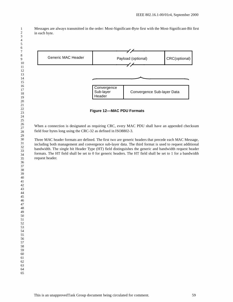
IEEE 802.16.1-00/01r4, September 2000
1234567891011121314151617181920212223242526272829303132333435363738394041424344454647484950515253545556575859606162636465
Messages are always transmitted in the order: Most-Significant-Byte first with the Most-Significant-Bit firstin each byte.
When a connection is designated as requiring CRC, every MAC PDU shall have an appended checksumfield four bytes long using the CRC-32 as defined in ISO8802-3.
Three MAC header formats are defined. The first two are generic headers that precede each MAC Message,including both management and convergence sub-layer data. The third format is used to request additionalbandwidth. The single bit Header Type (HT) field distinguishes the generic and bandwidth request headerformats. The HT field shall be set to 0 for generic headers. The HT field shall be set to 1 for a bandwidthrequest header.
Figure 12—MAC PDU Formats
Convergence Sub-layer Data
Generic MAC Header Payload (optional)
ConvergenceSub-layerHeader
CRC(optional)
This is an unapproved Task Group document being circulated for comment. 59

IEEE 802.16.1-00/01r4, September 2000
1234567891011121314151617181920212223242526272829303132333435363738394041424344454647484950515253545556575859606162636465
The format shown in Figure 13 shall be used for all PDUs transmitted by the SS to the BS in the uplinkdirection. For downlink transmissions, the format shown in Figure 14 shall be used.
CI
Figure 13—Generic MAC Header Format (Uplink)
LengthEC EKS
Connection Identifier
GM
HT FC FSN
Piggy-Back Request
Grants Per IntervalSI
SI PMUnsolicited Grant Service
Unsolicited Grant Servicewith Activity Detection
All others
Grant Management
CSI=0
Bit 0 8 15
HCS
Reserved
This is an unapproved Task Group document being circulated for comment. 60

IEEE 802.16.1-00/01r4, September 2000
1234567891011121314151617181920212223242526272829303132333435363738394041424344454647484950515253545556575859606162636465
These two generic header formats are equivalent with the exception of the Grant Mangament field, which isonly present in uplink transmissions.
The Grant Management (GM) field is one byte in length and is used by the SS to convey bandwidth manage-ment needs to the BS. This field is encoded differently based upon the type of connection (as given by theConnection ID). The use of this field is defined in Section 2.10.
The third header is a special format used by a SS to request additional bandwidth. This header shall alwaysbe transmitted without a PDU. The format of the Bandwidth Request Header is given in Figure 15.
The Bandwidth Request (BR) Header is used by a SS to request uplink bandwidth. A Bandwidth RequestHeader shall not have an associated payload:
The length of the header shall always be 7 bytes.The EC field shall be set to 1, indicating no encryption.The CID shall indicate the Service Flow for which uplink bandwidth is requested.
HCS
Figure 14—Generic MAC Header Format (Downlink)
LengthEC EKS
Connection Identifier
Bit 0 8 15
CIHT FC FSNCSI=0 Reserved
Figure 15—Bandwidth Request Header Format
Length (=7)
CID
HT BR
1
HCS
=1
0000
Bit 0 8 15
This is an unapproved Task Group document being circulated for comment. 61

IEEE 802.16.1-00/01r4, September 2000
1234567891011121314151617181920212223242526272829303132333435363738394041424344454647484950515253545556575859606162636465
The Bandwidth Request (BR) field shall indicate the number of bytes requested.
A SS receiving a Bandwidth Request Header on the downlink shall discard the PDU.
The various fields of the header formats are defined in Table 5. Every header is encoded starting with the ECand EKS fields. The coding of these fields is such that the first byte of a MAC header shall never have thevalue of 0xFX. This prevents false detection on the stuff byte used in the Transmission Convergence Sub-layer.
Table 5—MAC Header Fields
Name Length(bits) Description
BR 15 Bandwidth RequestThe number of bytes of uplink bandwidth requested by the CPE. The bandwidth request is for the CID. The request shall not include any PHY layer overhead
CID 16 Connection Identifier
CSI 1 Convergence Sub-layer IndicationThis bit is allocated to a convergence layer process for signaling between equivalent peers.
EC 1 Encryption Control1 = Payload is not encrypted0 = Payload is encrypted
EKS 4 Encryption Key SequenceThe index of the Traffic Encryption Key and Initialization Vector used to encrypt the pay-load. This field is only meaningful if the Encryption Control field is set to zero. This field must be set to all zeros when the EC is 1.
This is an unapproved Task Group document being circulated for comment. 62

IEEE 802.16.1-00/01r4, September 2000
1234567891011121314151617181920212223242526272829303132333435363738394041424344454647484950515253545556575859606162636465
Multiple MAC PDUs may be concatenated into a single transmission in either the uplink or downlink direc-tions. Figure 16 illustrates this concept for an uplink burst transmission. Since each PDU is identifiied by a
FC 2 Fragmentation ControlIndicates the fragmentation state of the payload:00 = no fragmentation01 = last fragment10 = first fragment11 = continuing (middle) fragment
FSN 4 Fragmentation Sequence NumberDefines the sequence number of the current fragment. The initial fragment (FC=10) sets this field to 0. This field increments by one (modulo 16) for each fragment.
When fragmentation is not used (FC= 00), this field shall be set to 0.
GPI 7 Grants Per IntervalThe number of grants required by a connection using UGS with Activity Detection
HCS 8 Header Check SequenceAn 8-bit field used to detect errors in the header. The generator polynomial is g(D)=D8 + D2 + D + 1.
HT 1 Header Type0 = Generic Header1 = Bandwidth Request Header
LEN 11 LengthThe length in bytes of the entire MAC header and any MAC PDU information that follows this specific header.
PBR 8 Piggy-Back RequestThe number of bytes of uplink bandwidth requested by the CPE. The bandwidth request is for the CID. The request shall not include any PHY layer overhead.
PM 1 Poll-Me0 = No action.1 = Used by the CPE to request a bandwidth poll.
SI 1 Slip Indicator0 = No action1 = Used by the CPE to indicate a slip of uplink grants relative to the uplink queue depth.
CI 1 CRC Indicator1 = CRC is appended to the PDU0 = No CRC is appended
Table 5—MAC Header Fields
Name Length(bits) Description
This is an unapproved Task Group document being circulated for comment. 63

IEEE 802.16.1-00/01r4, September 2000
1234567891011121314151617181920212223242526272829303132333435363738394041424344454647484950515253545556575859606162636465
unique Connection Identifier, the receiving MAC entity is able to present the PDU to the correct SAP . GrantManagement, user data, and bandwidth request PDUs may be concatenated into the same tranmission.
ARQ is optional for both the SS and the BS.
When ARQ is in use, the ARQ mechanism requires adding control and checksum fields to each ARQ-enabled packet. The checksum field is four bytes long, standard IEEE CRC-32, and it is appended at the endof the packet. The control field is two bytes long and is prepended at the beginning of the packet. The controlbit structure contains a 4-bit retry number and a 12 -bit sequence number. The retry number field is resetwhen a packet is first sent, and is incremented whenever it is retransmitted (up to the terminal value of 15).The sequence number field is assigned to each packet on its first transmission and then incremented. Thesequence number does not change when a packet is retransmitted. These ARQ-related fields are added onlyto packets for which ARQ is in use.
2.5.1 Convergence Sub-layer PDU Formats
The format of the convergence sub-layer PDU shall be as shown in Figure 17. A Convergence Sub-layerPDU may have a zero length payload. Convergence sublayer messages must not be transported on the Basic
Connection ID nor on the Secondary Managment CID.
2.5.2 MAC Management Messages
A set of management Messages are defined within the core MAC. These Messages shall use the standardMessage format as given in Section 2.5.1. All management Messages shall begin the payload content with asingle byte field indicating the management Message type. The format of the management Message is given
Figure 16—MAC PDU Concatenation showing example CIDs
User Bandwidth ManagementPDURquest PDUPDU
UserPDU
UserPDU
Uplink Burst #n Uplink Burst #n+1
CID = 0x2301 CID = 0x0399 CID = 0x0EF1 CID = 0x5F3E CID = 0x2555
Figure 17—Convergence Sub-layer PDU Format
Convergence Sub-layer Payload
Generic MAC Header
This is an unapproved Task Group document being circulated for comment. 64

IEEE 802.16.1-00/01r4, September 2000
1234567891011121314151617181920212223242526272829303132333435363738394041424344454647484950515253545556575859606162636465
in Figure 18. The encoding of the Message type field is given in Table 6. MAC management messages must
not be carried on Transport connections.
Table 6—MAC Management Messages
Type Message Name Message Description
0 UCD Uplink Channel Descriptor
1 DCD Downlink Channel Descriptor
2 DL-MAP Downlink Access Definition
3 UL-MAP Uplink Access Definition
4 RNG-REQ Ranging Request
5 RNG-RSP Ranging Response
6 REG-REQ Registration Request
7 REG-RSP Registration Response
8 REG-ACK Registration Acknowledge
9 PKM-REQ Privacy Key Management Request
10 PKM-RSP Privacy Key Management Response
11 DSA-REQ Dynamic Service Addition Request
12 DSA-RSP Dynamic Service Addition Response
13 DSA-ACK Dynamic Service Addition Acknowledge
Figure 18—MAC Management Message Format
Management Message Type
Management Message Payload
Generic Header
Bit 0 8 15
This is an unapproved Task Group document being circulated for comment. 65

IEEE 802.16.1-00/01r4, September 2000
1234567891011121314151617181920212223242526272829303132333435363738394041424344454647484950515253545556575859606162636465
2.5.2.1 Uplink Channel Descriptor (UCD) Message
An Uplink Channel Descriptor shall be transmitted by the BS at a periodic interval to define the characteris-tics of an upstream physical channel. A separate UCD Message shall be transmitted for each active uplink.
14 DSC-REQ Dynamic Service Change Request
15 DSC-RSP Dynamic Service Change Response
16 DSC-ACK Dynamic Service Change Acknowledge
17 DSD-REQ Dynamic Service Deletion Request
18 DSD-RSP Dynamic Service Deletion Response
19 DCC-REQ Dynamic Channel Change Request
20 DCC-RSP Dynamic Channel Change Response
21 MCA-REQ Multicast Assignment Request
22 MCA-RSP Multicast Assignment Response
23 DMC-REQ Downlink Burst Type Change Request
24 ARQ-ACK ARQ Acknowledgement
245-255 Reserved for future use
Table 6—MAC Management Messages
Type Message Name Message Description
This is an unapproved Task Group document being circulated for comment. 66

IEEE 802.16.1-00/01r4, September 2000
1234567891011121314151617181920212223242526272829303132333435363738394041424344454647484950515253545556575859606162636465
To provide for flexibility the message parameters following the channel ID shall be encoded in a type/length/value (TLV) form in which the type and length fields are each 1 long.
A BS shall generate UCDs in the format shown in Figure 19, including all of the following parameters:
Configuration Change Count
Incremented by one (modulo the field size) by the BS whenever any of the values of this channeldescriptor change. If the value of this count in a subsequent UCD remains the same, the SS canquickly decide that the remaining fields have not changed, and may be able to disregard the remain-der of the message. This value is also referenced from the UL-MAP messages.
Mini-Slot Size
The size T of the Mini-Slot for this uplink channel in units of Physical Slots. Allowable values are T
= 2m, where m = 0,...7.
Uplink Channel ID
The identifier of the uplink channel to which this Message refers. This identifier is arbitrarily chosenby the BS and is only unique within the MAC-Sublayer domain.
Figure 19—Uplink Channel Descriptor (UCD) Message Format
MAC Management Header
Uplink
TLV Encoded information for the overall channel
Mini-slot
TLV-encoded Burst Description (#n)
Channel IDConfigurationChange Count Size
DownlinkChannel ID
TLV-encoded Burst Description (#1)
0 8 16 24 31
This is an unapproved Task Group document being circulated for comment. 67

IEEE 802.16.1-00/01r4, September 2000
1234567891011121314151617181920212223242526272829303132333435363738394041424344454647484950515253545556575859606162636465
Downlink Channel ID
The identifier of the downlink channel on which this Message has been transmitted. This identifier isarbitrarily chosen by the BS and is only unique within the MAC-Sublayer domain.
All other parameters are coded as TLV tuples. The type values used shall be those defined in Table 7, forchannel parameters, and Table 9, for uplink physical layer burst attributes. Channel-wide parameters (fromTable 7) shall preceed burst descriptors (type 1 below).
Burst Descriptors are compound TLV encodings that define, for each type of uplink usage interval, the phys-ical-layer characteristics that are to be used during that interval. The uplink interval usage codes are defined
Table 7—Uplink Physical Channel Attributes
Name Type(1 byte)
Length(1 byte)
Value(Variable Length)
Burst Descriptor 1 May appear more than once; described below. The length is the number of bytes in the overall object, including embedded TLV items.
Symbol Rate 2 2 5 - 40 MBaud. The incremental rates are not yet defined for the PHY layer. The use of a TLV allows future clarification of this field without modification to the MAC.
Frequency 3 4 Uplink center frequency (kHz)
Preamble Pattern 4 1-128 Preamble superstring.
All burst-specific preamble values are chosen as bit-substrings of this string. The first byte of the Value field contains the first 8 bits of the superstring, with the first bit of the preamble superstring in the MSB position of the first Value field byte, the eighth bit of the preamble superstring in the LSB position of the first Value field byte; the second byte in the Value field contains the second eight bits of the superstring, with the ninth bit of the superstring in the MSB of the second byte and sixteenth bit of the preamble super-string in the LSB of the second byte, and so forth.
Tx/Rx Gap 5 1 The number of PS between the end of the downlink and uplink transmissions. This TLV is only used if the PHY Type field of the DL-MAP message is {0, 1} (TDD).
Rx/Tx Gap 6 1 The number of PS between the end of the uplink and downlink transmissions. This TLV is only used if the PHY Type field of the DL-MAP message is {0, 1} (TDD).
Roll-off factor 7 1 0=0.15, 1=0.25, 2=0.35
Spectrum inversion 8 1 0=inverted, 1=non-inverted
This is an unapproved Task Group document being circulated for comment. 68

IEEE 802.16.1-00/01r4, September 2000
1234567891011121314151617181920212223242526272829303132333435363738394041424344454647484950515253545556575859606162636465
Table 8—Uplink Map Information Elements
IE Name Uplink Interval
Usage
Code
(UIUC)
Connection
ID
Mini-slot Offset
Request 1 any Starting offset of REQ region
Initial
Maintenance
2 broadcast Starting offset of MAINT region (used in Initial Ranging)
Station
Maintenance
3 unicast Starting offset of MAINT region (used in Periodic Ranging)
Data Grant 1 4 unicast Starting offset of Data Grant assignment
If inferred length = 0, then it is a Data Grant pending.
Data Grant 2 5 unicast Starting offset of Data Grant assignment
If inferred length = 0, then it is a Data Grant Pending
Data Grant 3 6 unicast Starting offset of Data Grant 2 assignment
If inferred length = 0, then it is a Data Grant pending.
Data Grant 4 7 unicast Starting offset of Data Grant 2 assignment
If inferred length = 0, then it is a Data Grant pending.
Data Grant 5 8 unicast Starting offset of Data Grant 3 assignment
If inferred length = 0, then it is a Data Grant pending.
Data Grant 6 9 unicast Starting offset of Data Grant 3 assignment
If inferred length = 0, then it is a Data Grant pending.
Null IE 10 zero Ending offset of the previous grant.
Used to bound the length of the last actual interval allocation.
Empty 11 zero Used to schedule gaps in transmission
Reserved 11-14 any Reserved
Expansion 15 expanded
UIUC
# of additional 32-bit words in this IE
This is an unapproved Task Group document being circulated for comment. 69

IEEE 802.16.1-00/01r4, September 2000
1234567891011121314151617181920212223242526272829303132333435363738394041424344454647484950515253545556575859606162636465
in the UL-MAP Message. illustrates the format of each Burst Descruption TLV. Each TLV is encoded with aType of 1, an eight bit length, and a four bit UIUC.
A Burst Descriptor shall be included for each Interval Usage Code that is to be used in the UL-MAP. TheInterval Usage Code shall be one of the values from Table 13.
Within each Burst Descriptor is an unordered list of Physical-layer attributes, encoded as TLV values. Theseattributes are shown in Table 9.
2.5.2.2 Downlink Channel Descriptor (DCD) Message
A Downlink Channel Descriptor shall be transmitted by the BS at a periodic interval to define the character-istics of a downstram physical channel. A separate DCD message shall be transmitted for each active down-link.
Figure 20—Top-Level Encoding for a Burst Descriptor
Type = 1 Length1..n
TLV codes for PHY parameters
(Burst Descriptor) UIUC
This is an unapproved Task Group document being circulated for comment. 70

IEEE 802.16.1-00/01r4, September 2000
1234567891011121314151617181920212223242526272829303132333435363738394041424344454647484950515253545556575859606162636465
Table 9—Uplink Physical Layer Burst Profile Parameters
Name Type
(1 byte)
Length
(1 byte)
Value
(Variable Length)
Modulation Type 1 1 1 = QPSK, 2 = 16QAM, 3 = 64-QAM
Differential
Encoding
2 1 1 = on, 2 = off
Preamble Length 3 2 Up to 1024 bits. The preamble must be an integer number of PSs (a multiple of 2 for QPSK and 4 for 16QAM and 6 for 64QAM)
Preamble Value
Offset
4 2 Identifies the bits to be used for the preamble value. This is speci-fied as a starting offset into the Preamble Pattern (see Table 7). That is, a value of zero means that the first bit of the preamble for this burst type is the value of the first bit of the Preamble Pattern. A value of 100 means that the preamble is to use the 101st and succeeding bits from the Preamble Pattern. This value must be a multiple of the symbol size.
The first bit of the Preamble Pattern is the firstbit transmitted in the uplink burst.
FEC code type 5 1 1 = Reed-Solomon only
2 = Reed-Solomon + Inner (9,8) Parity Check Code
3 = Reed-Solomon + Inner (24,16) Block Convolutional Code
4 = Block Turbo Code (Optional)
5-255 = Reserved
RS information bytes (K)
6 1 K=6-255
RS error correction capability (T)
7 1 T=0-16
BCC code type 8 1 1 = (24,16)
2-255 = Reserved
This is an unapproved Task Group document being circulated for comment. 71

IEEE 802.16.1-00/01r4, September 2000
1234567891011121314151617181920212223242526272829303132333435363738394041424344454647484950515253545556575859606162636465
BTC Row code type 9 1 1 = (64,57) Extended Hamming
2 = (32,26) Extended Hamming
3-255 = Reserved
BTC Column code type
10 1 1 = (64,57) Extended Hamming
2 = (32,26) Extended Hamming
3-255 = Reserved
BTC Row code shortening
11 1 0-255 columns
BTC Column code shortening
12 1 0-255 rows
BTC Product code shortening bits
13 1 0-255 bits
Scrambler Seed 14 2 The 15-bit seed value left justified in the 2 byte field. Bit 15 is the MSB of the first byte and the LSB of the second byte is not used. (Not used if scrambler is off)
Guard Time Size 15 1 Number of PSs which must follow the end of this burst. (Although this value may be derivable from other network and architectural parameters, it is included here to ensure that the SSs and BS all use the same value.)
Last Codeword Length
16 1 1 = fixed; 2 = shortened
Scrambler on/off 17 1 1 = on; 2 = off
Convergence layer 18 1 0=enabled, 1=disabled
Table 9—Uplink Physical Layer Burst Profile Parameters
Name Type
(1 byte)
Length
(1 byte)
Value
(Variable Length)
This is an unapproved Task Group document being circulated for comment. 72

IEEE 802.16.1-00/01r4, September 2000
1234567891011121314151617181920212223242526272829303132333435363738394041424344454647484950515253545556575859606162636465
To provide for flexibility the message parameters following the channel ID shall be encoded in a type/length/value (TLV) form in which the type and length fields are each 1 long.
A BS shall generate DCDs in the format shown in Figure 21, including all of the following parameters:
Configuration Change Count
Incremented by one (modulo the field size) by the BS whenever any of the values of this channeldescriptor change. If the value of this count in a subsequent UCD remains the same, the SS canquickly decide that the remaining fields have not changed, and may be able to disregard the remain-der of the message. This value is also referenced from the UL-MAP messages.
Downlink Channel ID
The identifier of the downlink channel to which this Message refers. This identifier is arbitrarilychosen by the BS and is only unique within the MAC-Sublayer domain.
All other parameters are coded as TLV tuples. The type values used shall be those defined in Table 10, forchannel parameters, and Table 12, for downlink physical layer burst attributes. Channel-wide parameters(from Table 12) shall preceed burst descriptors (type 1 below).
Burst Descriptors are compound TLV encodings that define, for each type of downlink usage interval, thephysical-layer characteristics that are to be used during that interval. The downlink interval usage codes aredefined in the DL-MAP Message. The mapping between Burst Type and Downlink Interval Usage Code isgiven in Table 11.
Figure 21—Downlink Channel Descriptor (DCD) Message Format
MAC Management Header
Downlink
TLV-encoded Burst Description (#n)
Channel IDConfigurationChange Count
TLV-encoded Burst Description (#1)
0 8 16 24 31
This is an unapproved Task Group document being circulated for comment. 73

IEEE 802.16.1-00/01r4, September 2000
1234567891011121314151617181920212223242526272829303132333435363738394041424344454647484950515253545556575859606162636465
Table 10—Downlink Physical Channel Attributes
Name Type
(1 byte)
Length
(1 byte)
Value
(Variable Length)
Burst Descriptor 1 May appear more than once; described below. The length is the number of bytes in the overall object, including embedded TLV items.
BS Transmit Power 2 1 Signed in units of 1dB
Roll-off factor 3 1 0=0.15, 1=0.25, 2=0.35
FSDD/TDD frame time
8 4 The number of PS contained in a FSDD or TDD frame. This TLV is used only if the PHY Type field of the DL-MAP message is {0, 1, 3} (TDD, FSDD).
Table 11: Mapping of Burst Type to Downlink Interval Usage Code
Burst Type Downlink Interval Usage Code (DIUC)
Comments
reserved 0 TDM Burst Type 1 is well known
TDM Burst type 2 1
TDM Burst type 3 2
TDM Burst type 4 3
TDM Burst type 5 4
TDM Burst type 6 5
reserved 6-7
TDMA Burst type 1 8 TDM Burst Type 1 with re-sync preamble
TDMA Burst type 2 9 TDM Burst Type 2 with re-sync preamble
TDMA Burst type 3 10 TDM Burst Type 3 with re-sync preamble
TDMA Burst type 4 11 TDM Burst Type 4 with re-sync preamble
TDMA Burst type 5 12 TDM Burst Type 5 with re-sync preamble
TDMA Burst type 6 13 TDM Burst Type 6 with re-sync preamble
Gap 14 TDMA DL only
End of DL MAP 15
This is an unapproved Task Group document being circulated for comment. 74

IEEE 802.16.1-00/01r4, September 2000
1234567891011121314151617181920212223242526272829303132333435363738394041424344454647484950515253545556575859606162636465
Figure 22 illustrates the format of each Burst Description TLV. Each TLV is encoded with a Type of 1, aneight bit length, and a four bit DIUC. The IUC field is associated with the Downlink Burst Profile and
Thresholds. The IUC value is used in the DL-MAP message to specify the Burst Profile to be used for a spe-cific downlink burst.
Burst Type Thresholds
An optional parameter. The thresholds for transition between the various DIUC types on a downlinkchannel are specified by the BS for use by the SS.
Threshold Delta
An optional parameter. The delta about which a hysteresis is defined for transition of the SS betweenmodulation types. Used by the SS in conjuction with the 16-QAM and 64-QAM Thresholds to deter-mine when to request a modulation change for the downlink channel.
A Burst Descriptor shall be included for each Interval Usage Code that is to be used in the DL-MAP.
Within each Burst Descriptor is an unordered list of Physical-layer attributes, encoded as TLV values. Theseattributes are shown in Table 12.
Figure 22—Top-Level Encoding for a Downlink Burst Descriptor
Type = 1 Length1..n
TLV codes for PHY parameters
(Burst Descriptor) DIUC
This is an unapproved Task Group document being circulated for comment. 75

IEEE 802.16.1-00/01r4, September 2000
1234567891011121314151617181920212223242526272829303132333435363738394041424344454647484950515253545556575859606162636465
Table 12—Downlink Physical Layer Burst Profile Parameters
Name Type(1 byte)
Length(1 byte)
Value(Variable Length)
Modulation Type 1 1 1 = QPSK2 = 16QAM3 = 64-QAM
FEC code type 2 1 1 = Reed-Solomon only2 = Reed-Solomon + Inner (9,8) Parity Check Code3 = Reed-Solomon + Inner Block Convolutional Code4 = Block Turbo Code (Optional)5-255 = Reserved
RS information bytes (K) 3 1 K=6-255
RS error correction capability (T) 4 1 T=0-16
BCC code type 5 1 1 = (24,16)2-255 = Reserved
BTC Row code type 6 1 1 = (64,57) Extended Hamming2 = (32,26) Extended Hamming3-255 = Reserved
BTC Column code type 7 1 1 = (64,57) Extended Hamming2 = (32,26) Extended Hamming3-255 = Reserved
BTC Row code shortening 8 1 0-255 columns
BTC Column code shortening 9 1 0-255 rows
BTC Product code shortening bits
10 1 0-255 bits
Last codeword length 11 1 1=fixed; 2=shortened (optional)
This allows for the transmitter to shorten the last code-word, based upon the allowable shortened codewords for the particular code type.
IUC low threshold 13 1 C/I+N required for starting to use this IUC when a chang-ing to a more robust IUC is required, in ¼ dB units.
IUC high threshold 14 1 C/I+N required for starting to use this IUC when a chang-ing to a more less IUC is required, in ¼ dB units.
This is an unapproved Task Group document being circulated for comment. 76

IEEE 802.16.1-00/01r4, September 2000
1234567891011121314151617181920212223242526272829303132333435363738394041424344454647484950515253545556575859606162636465
2.5.3 Downlink MAP (DL-MAP) Message
The Downlink MAP (DL-MAP) message defines the access to the downlink information relative to the PHYmode. The DL-MAP message takes on different formats depending upon the value of the PHY Type field.
A BS shall generate DL-MAP messages in the format shown in Figure 23, including all of the followingparameters:
PHY Synchronization
A four byte field. The first three bits define the PHY type, as given by the following value:0 = TDD1 = FDD/TDM (Burst Downlink PHY)5 = FDD/TDM (Continuous Downlink PHY)
The remaining 29 bits are encoded as shown in Figure 24 for PHY Type = {0,1} or Figure 25 forPHY Type = 5. For burst downlink PHY operations, the bits are encoded as the frame number. Forcontinuous downlink PHY operations, the bits are encoded as a timestamp that synchronizes theuplink transmissions. For PHY type = 5, the time stamp represents the count state of the base stationcounter at the instant that the first byte of the Downlink MAP Message is transferred from theDownstream Transmission Convergence Sublayer to the Downstream Physical Media DependentSublayer. Figure 24 shows the 5 bits that encode the Frame Length types. They are defined by thefollowing values, which map to the frame times defined in section 3.2.2.
0 = 0.5 millisecond
Figure 23—Downlink MAP Message Format
MAC Management Header
Base Station ID[0:31]
PHY Synchronization
Base Station ID[32:63]
MAP Elements (PHY Type = {0,1})
This is an unapproved Task Group document being circulated for comment. 77

IEEE 802.16.1-00/01r4, September 2000
1234567891011121314151617181920212223242526272829303132333435363738394041424344454647484950515253545556575859606162636465
1 = 1 millisecond2 = 2 millisecondsAll other values are reserved.
The encoding of remaining portions of the DL-MAP message are also based upon the PHY field.For PHY Type = 5, no additional information follows the Base Station ID field. For PHY Type = {0,1}, a set of mapping information, as defined by the DL Burst Descriptors, is defined as in Figure 26.MAP information elements must be in time order, which is not neccessarily IUC order or connectionID order. For more information, refer to section 3.2.
The BS timestamp jitter must be less than 500 ns peak-to-peak at the output of the Downstream Transmis-sion Convergence Sublayer. This jitter is relative to an ideal Downstream Transmission Convergence Sub-layer that transfers the TC packet data to the Downstream Physical Media Dependent Sublayer with aperfectly continuous and smooth clock at symbol rate. Downstream Physical Media Dependent Sublayerprocessing shall not be considered in timestamp generation and transfer to the Downstream Physical MediaDependent Sublayer.
Thus, any two timestamps N1 and N2 (N2 > N1) which were transferred to the Downstream Physical MediaDependent Sublayer at times T1 and T2 respectively must satisfy the following relationship:
(N2 - N1)/(4 x Symbol Rate) - (T2 - T1) < 500 nsec
The jitter includes inaccuracy in timestamp value and the jitter in all clocks. The 500ns allocated for jitter atthe Downstream Transmission Convergence Sublayer output must be reduced by any jitter that is introducedby the Downstream Physical Media Dependent Sublayer.
Figure 24—PHY Synchronization Field (PHY Type = {0,1})
PHY Type Frame LengthCode
Frame Number
Frame Number
Figure 25—PHY Synchronization Field (PHY Type = 5)
PHY Type Uplink Timestamp[29:16]
Uplink Timestamp[15:0]
This is an unapproved Task Group document being circulated for comment. 78

IEEE 802.16.1-00/01r4, September 2000
1234567891011121314151617181920212223242526272829303132333435363738394041424344454647484950515253545556575859606162636465
The CID entry in the TDMA version of the DL-MAP message defines the allocation of bandwidth for thatconnection. For a SS operating in GPC mode, the CID shall be the Transport CID. For a SS operating inGPT mode, the CID shall be the Basic CID.
Figure 26—Downlink TDM MAP Message Element Format
Physical Slot Start #1
Downlink MAP Message
Physical Slot Start #n
DIUC
DIUC
This is an unapproved Task Group document being circulated for comment. 79

IEEE 802.16.1-00/01r4, September 2000
1234567891011121314151617181920212223242526272829303132333435363738394041424344454647484950515253545556575859606162636465
2.5.4 Uplink MAP (UL-MAP) Message
The Uplink MAP (UL-MAP) message allocates access to the upstream channel. The UL-MAP messageshall be as shown in Figure 27.
Uplink Channel ID
Figure 27—Uplink MAP Message Format
UL Channel ID UCD Count Number of Elements
Allocation Start Time
Acknowledgement Time
Ranging BackoffStart
Ranging BackoffEnd
Request BackoffStart
RequestBackoffEnd
UIUC OffsetConnection ID
UIUC Offset = 0Connection ID
Offset = map lengthConnection ID = 0
UIUC Offset = map lengthConnection ID(data grant pending)
UIUC Offset = map lengthConnection ID(data grant pending)
MAC Management Header
0 8 16 24 31
UIUC=10
This is an unapproved Task Group document being circulated for comment. 80

IEEE 802.16.1-00/01r4, September 2000
1234567891011121314151617181920212223242526272829303132333435363738394041424344454647484950515253545556575859606162636465
The identifier of the uplink channel to which this Message refers.UCD Count
Matches the value of the Configuration Change Count of theUCD which describes the burst parame-ters which apply to this map.
Number of Elements
Number of information elements in the map.
Alloc Start Time
Effective start time of the uplink allocation defined by the UL-MAP in units of mini-slots. The starttime is relative to the start of a frame in which UL-MAP message is transmitted (PHY Type ={0.,1,3}) or from BS initialization (PHY Type = 5).
Ack Time
Latest time processed in uplink in units of mini-slots. This time is used by the SS for collision detec-tion purposes. The ack time is relative to the start of a frame in which UL-MAP message is transmit-ted (PHY Type = {0,1,3}) or from BS initialization (PHY Type = 5).
Ranging Backoff Start
Initial back-off window size for initial ranging contention, expressed as a power of 2. Values of nrange 0-15 (the highest order bits must be unused and set to 0).
Ranging Backoff End
Final back-off window size for initial ranging contention, expressed as a power of 2. Values of nrange 0-15 (the highest order bits must be unused and set to 0).
Request Backoff Start
Initial back-off window size for contention data and requests, expressed as a power of 2. Values of nrange 0-15 (the highest order bits must be unused and set to 0).
Request Backoff End
Final back-off window size for contention requests, expressed as a power of 2. Values of n range 0-15 (the highest order bits must be unused and set to 0).
MAP Information Elements
Information elements define uplink bandwidth allocations. Each UL-MAP message shall contain atleast one Information Element. The format of the IE shall be as shown in Figure 28. Each IE consistsof three fields: a Connection Identifer, an Interval Usage Code, and an offset.
The Connection Identifier represent the assignment of the IE to either a unicast, multicast, or broad-cast address. When specifically addressed to allocate a bandwidth grant, the CID may be either theBasic CID of the SS or a Traffic CID for one of the connections of the SS. A four-bit DownlinkInterval Usage Code (DIUC) shall be used to define the type of uplink access and the burst type
This is an unapproved Task Group document being circulated for comment. 81

IEEE 802.16.1-00/01r4, September 2000
1234567891011121314151617181920212223242526272829303132333435363738394041424344454647484950515253545556575859606162636465
associated with that access. Table 13 defines the use of the IUCs. The offset shall be the length fromthe start of the previous IE to the start of this IE in units of mini-slots. The first IE shall have an off-set of 0.
Three pairs of data grant Information Elements are defined. This allows each pair to be assigned to a differ-ent burst profile pair, typically based upon modulation type. For example, the first pair would be assigned touse QPSK, the second pair would use 16-QAM, and the third would use 64-QAM. Within each pair, theshort and long grant usage is distinguished by the maximum burst size. This allows short PDU transmissionsfor services that are tolerant of packet loss to use less FEC coding (relative to longer grants).
2.5.5 Ranging Request (RNG-REQ) Message
A Ranging Request shall be transmitted by a SS at initialization and periodically on request from BS todetermine network delay and request power and/or modulation adjustment. This shall be followed by aPacket PDU in the format shown in Figure 29.
Figure 28—UL-MAP Information Element
Interval
Connection Identifier
Offset
Bit 0 8 15
Usage Code
Figure 29—RNG-REQ Message Format
Downlink Pending TilChannel ID Complete
TLV Encoded Information
MAC Management Header
This is an unapproved Task Group document being circulated for comment. 82

IEEE 802.16.1-00/01r4, September 2000
1234567891011121314151617181920212223242526272829303132333435363738394041424344454647484950515253545556575859606162636465
The RNG-REQ Message shall be transmitted using QPSK modulation.
Parameters shall be as follows:
CID (from the MAC Management Header)
For RNG-REQ Messages transmitted in Initial Maintenance intervals:Initialization CID if SS is attempting to join the networkInitialization CID if SS has not yet registered and is changing downlink (or both downlink anduplink) channels as directed by a downloaded parameter fileTemporary CID if SS has not yet registered and is changing uplink (not downlink) channels asdirected by a downloaded parameter file
Table 13—Uplink MAP Information Elements
IE Name Uplink Interval
Usage
Code
(UIUC)
Connection ID
Mini-slot Offset
Request 1 any Starting offset of REQ region
Initial
Maintenance
2 broadcast Starting offset of MAINT region (used in Initial Ranging)
Station
Maintenance
3 unicast Starting offset of MAINT region (used in Periodic Ranging)
Data Grant 1 4 unicast Starting offset of Data Grant assignment
If inferred length = 0, then it is a Data Grant pending.
Data Grant 2 5 unicast Starting offset of Data Grant assignment
If inferred length = 0, then it is a Data Grant Pending
Data Grant 3 6 unicast Starting offset of Data Grant 2 assignment
If inferred length = 0, then it is a Data Grant pending.
Data Grant 4 7 unicast Starting offset of Data Grant 2 assignment
If inferred length = 0, then it is a Data Grant pending.
Data Grant 5 8 unicast Starting offset of Data Grant 3 assignment
If inferred length = 0, then it is a Data Grant pending.
Data Grant 6 9 unicast Starting offset of Data Grant 3 assignment
If inferred length = 0, then it is a Data Grant pending.
Null IE 10 zero Ending offset of the previous grant.
Used to bound the length of the last actual interval allocation.
Empty 11 zero Used to schedule gaps in transmission
Reserved 11-14 any Reserved
Expansion 15 expanded UIUC
# of additional 32-bit words in this IE
This is an unapproved Task Group document being circulated for comment. 83

IEEE 802.16.1-00/01r4, September 2000
1234567891011121314151617181920212223242526272829303132333435363738394041424344454647484950515253545556575859606162636465
Registration CID (previously assigned in REG-RSP) if SS is registered and is changing uplink chan-nels
For RNG-REQ Messages transmitted in Station Maintenance intervals:Basic CID
Downlink Channel ID
The identifier of the downlink channel on which the SS received the DCD which described thisuplink. This is an 8-bit field.
Pending Till Complete
If zero, then all previous Ranging Response attributes have been applied prior to transmittting thisrequest. If nonzero then this is time estimated to be needed to complete assimilation of rangingparameters. Note that only equalization can be deferred. Units are in unsigned centiseconds (10msec).
All other parameters are coded as TLV tuples.
Requested downlink burst type
An optional parameter. Downlink burst types requested by the CPE for downlink traffic based on theIUC definitions coneyed by the DCD message, the CPE capabilities (i.e. which of the combinationsit supports), and on measurements of the downlink RF channel relative to the IUC transition thresh-olds (also defined in the DCD message).
SS MAC Address
A required parameter. The link-layer address of the SS.
Ranging Anomalies
An optional parameter indicating a potential error condition detected by the SS. Setting the bit asso-ciated with a specific condition indicates that the condition exists at the SS.
2.5.5.1 RNG-REQ TLV Encodings
The type values used shall be those defined in Table 14. These are unique within the ranging request Mes-sage but not across the entire MAC Message set. The type and length fields shall each be 1 in length.
2.5.6 Ranging Response (RNG-RSP) Message
A Ranging Response shall be transmitted by a BS in response to received RNG-REQ. It may be noted that,from the point of view of the SS, reception of a Ranging Response is stateless. In particular, the SS shall beprepared to receive a Ranging Response at any time, not just following a Ranging Request.
The RNG-RSP Message shall be transmitted using QPSK modulation.
To provide for flexibility, the Message parameters following the Uplink Channel ID shall be encoded in atype/length/value (TLV) form.
This is an unapproved Task Group document being circulated for comment. 84

IEEE 802.16.1-00/01r4, September 2000
1234567891011121314151617181920212223242526272829303132333435363738394041424344454647484950515253545556575859606162636465
A BS shall generate Ranging Responses in the form shown in Figure 30, including all of the followingparameters:
Uplink Channel ID
The identifier of the uplink channel on which the BS received the RNG-REQ to which this responserefers.
All other parameters are coded as TLV tuples.
Timing Adjust Information
Table 14—Ranging Request Message Encodings
Name Type
(1 byte)
Length
(1 byte)
Value
(Variable Length)
Requested Down-link Burst Type
1 1 Downlink IUC for requested burst type
SS MAC Address 2 6 SS MAC Address
Ranging Anomalies 3 1 Bit #0 - SS already at maximum power. Bit #1 - SS already at minimum power. Bit #2 - Sum of commanded timing adjustments is too
large.
Reserved 4-255 n Reserved for future use
Figure 30—RNG-RSP Message Format
TLV Encoded Information
MAC Management Header
UplinkChannel ID
This is an unapproved Task Group document being circulated for comment. 85

IEEE 802.16.1-00/01r4, September 2000
1234567891011121314151617181920212223242526272829303132333435363738394041424344454647484950515253545556575859606162636465
The time by which to offset frame transmission so that frames arrive at the expected mini-slot timeat the BS.
Power Adjust Information
Specifies the relative change in transmission power level that the SS is to make in order that trans-missions arrive at the BS at the desired power.
Frequency Adjust Information
Specifies the relative change in transmission frequency that the SS is to make in order to bettermatch the BS. (This is fine-frequency adjustment within a channel, not re-assignment to a differentchannel)
Ranging Status
Used to indicate whether uplink Messages are received within acceptable limits by BS.
Downlink Frequency Override
An optional parameter. The downlink frequency with which the SS should redo initial ranging.
Uplink Channel ID Override
An optional parameter. The identifier of the uplink channel with which the SS should redo initialranging.
Requested DL Modulation Maximum Modulation Type Supported
An optional parameter. The maximum allowed set of Modulation types allowed for the SS for down-link traffic. This parameter is sent in response to the RNG-REQ Modulation Type from the SS. TheSS responds with the maximum allowed set of modulation types based upon the combination of therequested modulation type and the maximum allowable modulation type determined at registrationor from a dynamic service operation.
CID
.A required parameter until the Temporary CID has been received in the Ranging Response mes-sage. Note that in all other cases, the CID is encoded in the MAC Management Header and is notsent as a TLV.
SS MAC Address (48- Bit)
The MAC address of the SS. A required parameter when the CID in the MAC header is the initial-ization CID.
This is an unapproved Task Group document being circulated for comment. 86

IEEE 802.16.1-00/01r4, September 2000
1234567891011121314151617181920212223242526272829303132333435363738394041424344454647484950515253545556575859606162636465
2.5.6.1 RNG-RSP TLV Encodings
The type values used shall be those defined in Table 15 and Figure 33. These are unique within the rangingresponse Message but not across the entire MAC Message set. The type and length fields shall each be 1 inlength.
Table 15—Ranging Response Message Encodings
Name Type
(1 byte)
Length
(1 byte)
Value
(Variable Length)
Timing Adjust 1 4 Tx timing offset adjustment (signed 32-bit, units of ¼ symbols)
Power Level Adjust 2 1 Tx Power offset adjustment (signed 8-bit, ¼-dB units)
Offset Frequency Adjust
3 4 Tx frequency offset adjustment (signed 32-bit, Hz units)
Transmit Equaliza-tion Adjust
4 n Tx equalization data - see details below
Ranging Status 5 1 1 = continue, 2 = abort, 3 = success
Downlink frequency override
6 4 Center frequency of new downlink channel in kHz
If this TLV is used, the Ranging Status value must be set to 1
Uplink channel ID override
7 1 Identifier of the new uplink channel.
Data Grant 1-6
Thresholds
8 1 TBD
Threshold Delta 10 1 Hysteresis delta for modulation threholds in ¼ dB.
Maximum Modu-lation Type
Supported
11 1 1 = QPSK, 2 = QPSK or 16-QAM, 3 = QPSK or 16/64-QAM
SS MAC
Address
12 8 SS MAC Address in EUI-48 format
Reserved 13-255 n Reserved for future use
This is an unapproved Task Group document being circulated for comment. 87

IEEE 802.16.1-00/01r4, September 2000
1234567891011121314151617181920212223242526272829303132333435363738394041424344454647484950515253545556575859606162636465
The number of forward taps per symbol shall be in the range of 1 to 4. The main tap location refers to theposition of the zero delay tap, between 1 and N. For a symbol-spaced equalizer, the number of forward tapsper symbol field shall be set to “1”. The number of reverse taps (M) field shall be set to “0” for a linearequalizer. The total number of taps may range up to 64. Each tap consists of a real and imaginary coefficiententry in the table.
If more than 255 bytes are needed to represent equalization information, then several type-4 elements maybe used. Data shall be treated as if byte-concatenated, that is, the first byte after the length field of the secondtype-4 element is treated as if it immediately followed the last byte of the first type-4 element.
Figure 31—Generalized Decision Feedback Equalization Coefficients
last coefficient FN ( im ag)
first reverse coefficient D1(im ag)
last reverse coefficient DM(im ag)
last coefficient FN (real)
first reverse coefficient D1(real)
last reverse coefficient DM(real)
type4
length num ber of forwardtaps per sym bol
num ber offorward taps (N)
num ber ofreverse taps (M )
m ain taplocation
first coeffic ient F1 (real) first coeffic ient F1 ( im ag)
Figure 32—Generalized Equalizer Tap Location Definition
F 3
D 5
F4
D 4
F 5
D 3
F 6
D 2
F2
D 6
F1
D M
Z-T
Z-R
F N
D 1
E qua lizerInpu t
E qua lizerO utpu t
Z-R Z-R Z-R Z-R Z-R
Z-T Z-T Z-T Z-T Z-T Z-T
R = T, T /2 , T /4
This is an unapproved Task Group document being circulated for comment. 88

IEEE 802.16.1-00/01r4, September 2000
1234567891011121314151617181920212223242526272829303132333435363738394041424344454647484950515253545556575859606162636465
2.5.7 Registration Request (REG-REQ) Message
A Registration Request shall be transmitted by a SS at initialization allowing the CID shall be encoded in atype/length/value form. A SS shall generate Registration Requests in the form shown in Figure 33
CID (from the MAC Management Header)
Temporary CID for this SS.
All other parameters are coded as TLV tuples as defined in 2.3.
Registration Requests can contain many different TLV parameters, some of which are set by the SS accord-ing to its configuration file and some of which are generated by the SS itself. If found in the ConfigurationFile, the following Configuration Settings shall be included in the Registration Request.
Configuration File Settings:
Downlink Frequency Configuration SettingUplink Channel ID Configuration SettingNetwork access Control ObjectUplink Service Flow Configuration SettingDownlink Service Flow Configuration SettingPrivacy Configuration SettingMaximum Number of SubscribersPrivacy Enable Configuration SettingTFTP Server TimestampTFTP Server Provisioned SS addressDownlink Modulation Configuration SettingVendor-Specific Information Configuration SettingSS MIC Configuration SettingBS MIC Configuration Setting
The SS shall forward the vendor specific configuration settings to the BS in the same order in which they werereceived in the configuration file to allow the Message integrity check to be performed.
Figure 33—REG-REQ Message Format
TLV Encoded Information
MAC Management Header
This is an unapproved Task Group document being circulated for comment. 89

IEEE 802.16.1-00/01r4, September 2000
1234567891011121314151617181920212223242526272829303132333435363738394041424344454647484950515253545556575859606162636465
The following registration parameter shall be included in the Registration Request.
Vendor Specific Parameter:
Vendor ID Configuration Setting (Vendor ID of SS)
The following registration parameter shall also be included in the Registration Request.
Upstream and Downstream SS Capabilities EncodingsThese include the highest modulation order supported by the SS (QPSK,16-QAM, or 64-QAM), the optional FEC types supported by the SS(BTC1 basedon (32,26) Extended Hamming Code or BTC2 based on (64,57) Extended HammingCode), and the minimum shortened last codeword size supported by the SS
The following registration parameter may also be included in the Registration Request.
SS IP address
The following Configuration Settings shall not be forwarded to the BS in the Registration Request.
Software Upgrade Filename Software Upgrade TFTP Server IP addressSNMP Write-access ControlSNMP MIB ObjectSS 48-bit MAC addressHMAC DigestEnd Configuration SettingPad Configuration Setting
2.5.8 Registration Response (REG-RSP) Message
A Registration Response shall be transmitted by BS in response to received REG-REQ.
This is an unapproved Task Group document being circulated for comment. 90
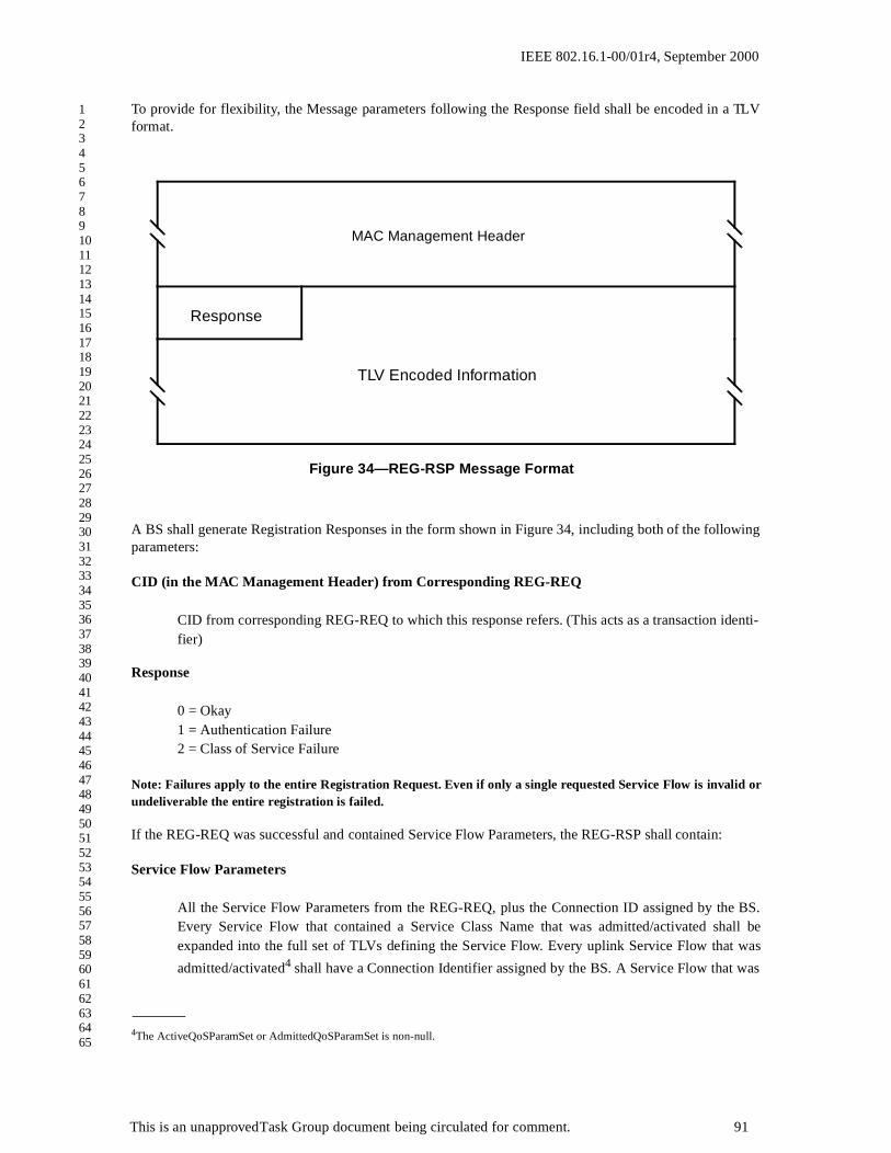
IEEE 802.16.1-00/01r4, September 2000
1234567891011121314151617181920212223242526272829303132333435363738394041424344454647484950515253545556575859606162636465
To provide for flexibility, the Message parameters following the Response field shall be encoded in a TLVformat.
A BS shall generate Registration Responses in the form shown in Figure 34, including both of the followingparameters:
CID (in the MAC Management Header) from Corresponding REG-REQ
CID from corresponding REG-REQ to which this response refers. (This acts as a transaction identi-fier)
Response
0 = Okay1 = Authentication Failure2 = Class of Service Failure
Note: Failures apply to the entire Registration Request. Even if only a single requested Service Flow is invalid orundeliverable the entire registration is failed.
If the REG-REQ was successful and contained Service Flow Parameters, the REG-RSP shall contain:
Service Flow Parameters
All the Service Flow Parameters from the REG-REQ, plus the Connection ID assigned by the BS.Every Service Flow that contained a Service Class Name that was admitted/activated shall beexpanded into the full set of TLVs defining the Service Flow. Every uplink Service Flow that was
admitted/activated4 shall have a Connection Identifier assigned by the BS. A Service Flow that was
4The ActiveQoSParamSet or AdmittedQoSParamSet is non-null.
Figure 34—REG-RSP Message Format
TLV Encoded Information
Response
MAC Management Header
This is an unapproved Task Group document being circulated for comment. 91

IEEE 802.16.1-00/01r4, September 2000
1234567891011121314151617181920212223242526272829303132333435363738394041424344454647484950515253545556575859606162636465
only provisioned will include only those QoS parameters that appeared in the REG-REQ, plus theassigned Service Flow ID.
If the REG-REQ failed and contained Service Flow Parameters, the REG-RSP shall contain the following:
Service Flow Error Set
A Service Flow Error Set and identifying Service Flow Reference shall be included for every failedService Flow in the corresponding REG-REQ. Every Service Flow Error Set shall include everyspecific failed QoS Parameter of the corresponding Service Flow.
Service Class Name expansion always occurs at admission time. Thus, if a Registration-Request contains aService Flow Reference and a Service Class Name for deferred admission/activation, the Registration-Response shall not include any additional QoS Parameters except the Service Flow Identifier.
All other parameters are coded as TLV tuples:
Basic CID
The Basic CID for this SS.
Secondary Management CID
CID for secondary management purposes
SS Capabilities
The BS response to the capabilities of the SS (if present in the Registration Request)
Vendor-Specific Data
As defined in 2.3Vendor ID Configuration Setting (vendor ID of BS)Vendor-specific extensions
Note: The temporary CID shall no longer be used once the REG-RSP is received.
2.5.8.1 Encodings
The type values used shall be those shown below. These are unique within the Registration Response Mes-sage but not across the entire MAC Message set. The type and length fields shall each be 1 .
SS Capabilities
This field defines the BS response to the SScapability field in the Registration Request. The BSresponds to the SS capabilities to indicate whether they may be used. If the BS does not recognize aSS capability, it must return this as “off” in the Registration Response.
Only capabilities set to “on” in the REG-REQ may be set “on” in the REG-RSP as this is the hand-shake indicating that they have been successfully negotiated.
Encodings are as defined for the Registration Request, including MAC version.
This is an unapproved Task Group document being circulated for comment. 92

IEEE 802.16.1-00/01r4, September 2000
1234567891011121314151617181920212223242526272829303132333435363738394041424344454647484950515253545556575859606162636465
2.5.9 Registration Acknowledge (REG-ACK) Message
A Registration Acknowledge message shall be transmitted by the SS in response to a REG-RSP from theBS. It confirms acceptance by the SS of the QoS parameters of the flow as reported by the BS in it REG-RSP. The format of a REG-ACK shall be as shown in Figure 35.
The parameter shall be as follows:
CID (in the MAC Management Header) from Corresponding REG-RSP
CID from corresponding REG-RSP to which this acknowledgment refers. (This acts as a transactionidentifier)
Confirmation Code
The appropriate Confirmation Code (refer to section 2.3) for the entire corresponding RegistrationResponse.
The SS shall forward all provisioned Service Flows to the BS. Since any of these provisioned items can fail,the REG-ACK shall include Error Sets for all failures related to these provisioned items.
Service Flow Error Set
The Service Flow Error Set of the REG-ACK Message encodes specifics of any failed ServiceFlows in the REG-RSP Message. A Service Flow Error Set and identifying Service Flow Reference
MAC Version 9 1 Version number of the MAC supported on this channel.
Figure 35—REG-ACK Message Format
TLV Encoded Information
ConfirmationCode
MAC Management Header
This is an unapproved Task Group document being circulated for comment. 93

IEEE 802.16.1-00/01r4, September 2000
1234567891011121314151617181920212223242526272829303132333435363738394041424344454647484950515253545556575859606162636465
shall be included for every failed QoS Parameter of every failed Service Flow in the correspondingREG-RSP Message. This parameter shall be omitted if the entire REG-REQ/RSP is successful.
Note: Per Service Flow acknowledgment is necessary not just for synchronization between the SS and BS, but also tosupport use of the Service Class Name. Since the SS may not know all of the Service Flow parameters associated with aService Class Name when making the Registration Request, it may be necessary for the SS to NAK a RegistrationResponse if it has insufficient resources to actually support this Service Flow.
2.5.10 Privacy Key Management — Request (PKM-REQ) Message
Privacy Key Management protocol Messages transmitted from the SS to the BS shall use the form shown inFigure 36.
Parameters shall be as follows:
PKM Code
The Code field is one octect and identifies the type of PKM packet. When a packet is recieved withan invalid Code field, it shall be silently discarded. The Code values are defined in 2.16.2.1.
PKM Identifier
The Identifier field is one octect. A SS uses the identifier to match a BS response to the SS’srequests.
The SS shall change (e.g., increment, wrapping around to 0 after reaching 255) the Identifier fieldwhenever it issues a new PKM Message. A "new" Message is an Authorization Request, KeyRequest or SA Map Request that is not a retransmission being sent in response to a Timeout event.For retransmissions, the Identifier field shall remain unchanged.
Figure 36—PKM-REQ Message Format
TLV Encoded Information
LengthPKM Code PKM Identifier
MAC Management Header
This is an unapproved Task Group document being circulated for comment. 94

IEEE 802.16.1-00/01r4, September 2000
1234567891011121314151617181920212223242526272829303132333435363738394041424344454647484950515253545556575859606162636465
The Identifier field in Authentication Information Messages, which are informative and do not effectany response messaging, may be set to zero. The Identifier field in a BS’s PKM response Messageshall match the Identifier field of the PKM Request Message the BS is responding to. The Identifierfield in Traffic Encryption Key (TEK) Invalid Messages, which are not sent in response to BPKMrequests, shall be set to zero. The Identifier field in unsolicited Authorization Invalid Messages shallbe set to zero.
On reception of a BPKM response Message, the SS associates the Message with a particular statemachine (the Authorization state machine in the case of Authorization Replies, AuthorizationRejects, and Authorization Invalids; a particular TEK state machine in the case of Key Replies, KeyRejects and TEK Invalids; a particular Security Association (SA) Mapping state machine in the caseof SA Map Replies and SA Map Rejects).
A SS may keep track of the Identifier of its latest, pending Authorization Request. The SS maysilently discard Authorization Replies and Authorization Rejects whose Identifier fields do notmatch those of the pending requests.
A SS may keep track of the Identifier of its latest, pending Key Request. The SS may silently discardKey Replies and Key Rejects whose Identifier fields do not match those of the pending requests.
A SS may keep track of the Identifier of its latest, pending SA Map Request. The SS may silentlydiscard SA Map Replies and SA Map Rejects whose Identifier fields do not match those of the pend-ing requests.
Length
The Length field is two s. It indicates the length of the Attribute fields in s. The length field does notinclude the Code, Identifier and Length fields. s outside the range of the Length field shall be treatedas padding and ignored on reception. If the packet is shorter than the Length field indicates, it shouldbe silently discarded. The minimum length is 0 and maximum length is <TBD>.
All other parameters are encoded as TLV tuples as defined in 2.3.
2.5.11 Privacy Key Management — Response (PKM-RSP) Message
Privacy Key Management protocol Messages transmitted from the BS to the SS shall use the form shown inFigure 37.
This is an unapproved Task Group document being circulated for comment. 95

IEEE 802.16.1-00/01r4, September 2000
1234567891011121314151617181920212223242526272829303132333435363738394041424344454647484950515253545556575859606162636465
2.5.12 Dynamic Service Addition — Request (DSA-REQ) Message
A Dynamic Service Addition Request may be sent by a SS or BS to create a new Service Flow.
Figure 37—PKM-RSP Message Format
TLV Encoded Information
LengthPKM Code PKM Identifier
MAC Management Header
Figure 38—DSA-REQ Message Format
Transaction ID
TLV Encoded Information
MAC Management Header
This is an unapproved Task Group document being circulated for comment. 96

IEEE 802.16.1-00/01r4, September 2000
1234567891011121314151617181920212223242526272829303132333435363738394041424344454647484950515253545556575859606162636465
A SS or BS shall generate DSA-REQ Messages in the form shown in Figure 38 including the followingparameter:
Transaction ID
Unique identifier for this transaction assigned by the sender.
All other parameters are coded as TLV tuples as defined in 2.3. A DSA-REQ Message shall not containparameters for more than one Service Flow in each direction, i.e., a DSA-REQ Message shall containparameters for either a single uplink Service Flow, or for a single downlink Service Flow, or for one uplinkand one downlink Service Flow.
The DSA-REQ Message shall contain:
Service Flow Parameters
Specification of the Service Flow’s traffic characteristics and scheduling requirements.
If Privacy is enabled, the DSA-REQ Message shall contain:
HMAC-Digest
The HMAC-Digest Attribute is a keyed Message digest (to authenticate the sender). The HMAC-Digest Attribute shall be the final Attribute in the Dynamic Service Message’s Attribute list. (Referto 2.3.4.1)
2.5.12.1 SS-Initiated Dynamic Service Addition
Values of the Service Flow Reference are local to the DSA Message; each Service Flow within the DSA-Request shall be assigned a unique Service Flow Reference. This value need not be unique with respect tothe other service flows known by the sender.
SS-initiated DSA-Requests may use the Service Class Name (refer to 2.3.5.3.4) in place of some, or all, ofthe QoS Parameters.
2.5.12.2 BS-Initiated Dynamic Service Addition
BS-initiated DSA-Requests for Uplink Service Flows shall also include a Connection ID. Connection Identi-fiers are unique within the MAC domain.
BS-initiated DSA-Requests for named Service Classes shall include the QoS Parameter Set associated withthat Service Class.
2.5.13 Dynamic Service Addition — Response (DSA-RSP) Message
A Dynamic Service Addition Response shall be generated in response to a received DSA-Request. The for-mat of a DSA-RSP shall be as shown in Figure 39.
This is an unapproved Task Group document being circulated for comment. 97

IEEE 802.16.1-00/01r4, September 2000
1234567891011121314151617181920212223242526272829303132333435363738394041424344454647484950515253545556575859606162636465
Parameters shall be as follows:
Transaction ID
Transaction ID from corresponding DSA-REQ.
Confirmation Code
The appropriate Confirmation Code for the entire corresponding DSA-Request.
All other parameters are coded as TLV tuples as defined in 2.3.
If the transaction is successful, the DSA-RSP may contain the following:
Service Flow Parameters
The complete specification of the Service Flow shall be included in the DSA-RSP only if it includesa newly assigned Connection Identifier or an expanded Service Class Name.
If the transaction is unsuccessful, the DSA-RSP shall include:
Service Flow Error Set
A Service Flow Error Set and identifying Service Flow Reference/Identifier shall be included forevery failed Service Flow in the corresponding DSA-REQ Message. Every Service Flow Error Setshall include every specific failed QoS Parameter of the corresponding Service Flow. This parametershall be omitted if the entire DSA-REQ is successful.
Figure 39—DSA-RSP Message Format
Transaction ID
TLV Encoded Information
ConfirmationCode
MAC Management Header
This is an unapproved Task Group document being circulated for comment. 98

IEEE 802.16.1-00/01r4, September 2000
1234567891011121314151617181920212223242526272829303132333435363738394041424344454647484950515253545556575859606162636465
If Privacy is enabled, the DSA-RSP Message shall contain:
HMAC-Digest
The HMAC-Digest Attribute is a keyed Message digest (to authenticate the sender). The HMAC-Digest Attribute shall be the final Attribute in the Dynamic Service Message’s Attribute list. (Referto 2.3.4.1)
2.5.13.1 SS-Initiated Dynamic Service Addition
The BS’s DSA-Response for Service Flows that are successfully added shall contain a Connection ID. TheDSA-Response for successfully Admitted or Active uplink QoS Parameter Sets shall also contain a Connec-tion ID.
If the corresponding DSA-Request uses the Service Class Name (refer to 2.3.5.3.4) to request service addi-tion, a DSA-Response shall contain the QoS Parameter Set associated with the named Service Class. If theService Class Name is used in conjunction with other QoS Parameters in the DSA-Request, the BS shallaccept or reject the DSA-Request using the explicit QoS Parameters in the DSA-Request. If these ServiceFlow Encodings conflict with the Service Class attributes, the BS shall use the DSA-Request values as over-rides for those of the Service Class.
If the transaction is unsuccessful, the BS shall use the original Service Flow Reference to identify the failedparameters in the DSA-RSP.
2.5.13.2 BS-Initiated Dynamic Service Addition
If the transaction is unsuccessful, the SS shall use the Connection Identifier to identify the failed parametersin the DSA-RSP.
2.5.14 Dynamic Service Addition — Acknowledge (DSA-ACK) Message
A Dynamic Service Addition Acknowledge shall be generated in response to a received DSA-RSP. The for-mat of a DSA-ACK shall be as shown in Figure 40.
This is an unapproved Task Group document being circulated for comment. 99

IEEE 802.16.1-00/01r4, September 2000
1234567891011121314151617181920212223242526272829303132333435363738394041424344454647484950515253545556575859606162636465
Parameters shall be as follows:
Transaction ID
Transaction ID from corresponding DSA-Response.
Confirmation Code
The appropriate Confirmation Code (refer to 2.3.7) for the entire corresponding DSA-Response.5
All other parameters are coded TLV tuples.
Service Flow Error Set
The Service Flow Error Set of the DSA-ACK Message encodes specifics of any failed ServiceFlows in the DSA-RSP Message. A Service Flow Error Set and identifying Service Flow Referenceshall be included for every failed QoS Parameter of every failed Service Flow in the correspondingDSA-REQ Message. This parameter shall be omitted if the entire DSA-REQ is successful.
If Privacy is enabled, the DSA-ACK Message shall contain:
HMAC-Digest
5The confirmation code is necessary particularly when a Service Class Name (refer to 2.3.5.3.4) is used in the DSA-Request. In thiscase, the DSA-Response could contain Service Flow parameters that the SS is unable to support (either temporarily or as configured).
Figure 40—DSA-ACK Message Format
Transaction ID
TLV Encoded Information
ConfirmationCode
MAC Management Header
This is an unapproved Task Group document being circulated for comment. 100

IEEE 802.16.1-00/01r4, September 2000
1234567891011121314151617181920212223242526272829303132333435363738394041424344454647484950515253545556575859606162636465
The HMAC-Digest Attribute is a keyed Message digest (to authenticate the sender). The HMAC-Digest Attribute shall be the final Attribute in the Dynamic Service Message’s Attribute list. (Referto 2.3.4.1)
2.5.15 Dynamic Service Change — Request (DSC-REQ) Message
A Dynamic Service Change Request may be sent by a SS or BS to dynamically change the parameters of anexisting Service Flow.
A SS or BS shall generate DSC-REQ Messages in the form shown in Figure 41 including the followingparameters:
Transaction ID
Unique identifier for this transaction assigned by the sender.
All other parameters are coded as TLV tuples as defined in 2.3. A DSC-REQ Message shall not carry param-eters for more than one Service Flow in each direction, i.e., a DSC-REQ Message shall contain parametersfor either a single uplink Service Flow, or for a single downlink Service Flow, or for one uplink and onedownlink Service Flow. A DSC-REQ shall contain the following:
Service Flow Parameters
Specification of the Service Flow’s new traffic characteristics and scheduling requirements. TheAdmitted and Active Quality of Service Parameter Sets currently in use by the Service Flow. If theDSC Message is successful and it contains Service Flow parameters, but does not contain replace-
Figure 41—DSC-REQ Message Format
Transaction ID
TLV Encoded Information
MAC Management Header
This is an unapproved Task Group document being circulated for comment. 101

IEEE 802.16.1-00/01r4, September 2000
1234567891011121314151617181920212223242526272829303132333435363738394041424344454647484950515253545556575859606162636465
ment sets for both Admitted and Active Quality of Service Parameter Sets, the omitted set(s) shall beset to null. If included, the Service Flow Parameters shall contain a Service Flow Identifier.
If Privacy is enabled, a DSC-REQ shall also contain:
HMAC-Digest
The HMAC-Digest Attribute is a keyed Message digest (to authenticate the sender). The HMAC-Digest Attribute shall be the final Attribute in the Dynamic Service Message’s Attribute list. (Referto 2.3.4.1)
2.5.16 Dynamic Service Change — Response (DSC-RSP) Message
A Dynamic Service Change Response shall be generated in response to a received DSC-REQ. The format ofa DSC-RSP shall be as shown in Figure 42.
Parameters shall be as follows:
Transaction ID
Transaction ID from corresponding DSC-REQ
Confirmation Code
The appropriate Confirmation Code (refer to 2.3.7) for the corresponding DSC-Request.
All other parameters are coded as TLV tuples as defined in 2.3.
Figure 42—DSC-RSP Message Format
Transaction ID
TLV Encoded Information
ConfirmationCode
MAC Management Header
This is an unapproved Task Group document being circulated for comment. 102

IEEE 802.16.1-00/01r4, September 2000
1234567891011121314151617181920212223242526272829303132333435363738394041424344454647484950515253545556575859606162636465
If the transaction is successful, the DSC-RSP may contain the following:
Service Flow Parameters
The complete specification of the Service Flow shall be included in the DSC-RSP only if it includesa newly assigned Connection Identifier or an expanded Service Class Name. If a Service FlowParameter set contained an uplink Admitted QoS Parameter Set and this Service Flow does not havean associated CID, the DSC-RSP shall include a CID. If a Service Flow Parameter set contained aService Class Name and an Admitted QoS Parameter Set, the DSC-RSP shall include the QoSParameter Set corresponding to the named Service Class. If specific QoS Parameters were alsoincluded in the Classed Service Flow request, these QoS Parameters shall be included in the DSC-RSP instead of any QoS Parameters of the same type of the named Service Class.
If the transaction is unsuccessful, the DSC-RSP shall contain the following:
Service Flow Error Set
A Service Flow Error Set and identifying Connection ID shall be included for every failed ServiceFlow in the corresponding DSC-REQ Message. Every Service Flow Error Set shall include everyspecific failed QoS Parameter of the corresponding Service Flow. This parameter shall be omitted ifthe entire DSC-REQ is successful.
Regardless of success or failure, if Privacy is enabled for the SS the DSC-RSP shall contain:
HMAC-Digest
The HMAC-Digest Attribute is a keyed Message digest (to authenticate the sender). The HMAC-Digest Attribute shall be the final Attribute in the Dynamic Service Message’s Attribute list. (Referto 2.3.4.1)
2.5.17 Dynamic Service Change — Acknowledge (DSC-ACK) Message
A Dynamic Service Change Acknowledge shall be generated in response to a received DSC-RSP. The for-mat of a DSC-ACK shall be as shown in Figure 43.
This is an unapproved Task Group document being circulated for comment. 103

IEEE 802.16.1-00/01r4, September 2000
1234567891011121314151617181920212223242526272829303132333435363738394041424344454647484950515253545556575859606162636465
Parameters shall be as follows:
Transaction ID
Transaction ID from the corresponding DSC-REQ
Confirmation Code
The appropriate Confirmation Code (refer to 2.3.7) for the entire corresponding DSC-Response.
All other parameters are coded TLV tuples.
Service Flow Error Set
The Service Flow Error Set of the DSC-ACK Message encodes specifics of any failed Service Flowsin the DSC-RSP Message. A Service Flow Error Set and identifying Service Flow Identifier shall beincluded for every failed QohS Parameter of each failed Service Flow in the corresponding DSC-RSP Message. This parameter shall be omitted if the entire DSC-RSP is successful.
If Privacy is enabled, the DSC-ACK Message shall contain:
HMAC-Digest
The HMAC-Digest Attribute is a keyed Message digest (to authenticate the sender). The HMAC-Digest Attribute shall be the final Attribute in the Dynamic Service Message’s Attribute list. (Referto 2.3.4.1)
Figure 43—DSC-ACK Message Format
Transaction ID
TLV Encoded Information
ConfirmationCode
MAC Management Header
This is an unapproved Task Group document being circulated for comment. 104

IEEE 802.16.1-00/01r4, September 2000
1234567891011121314151617181920212223242526272829303132333435363738394041424344454647484950515253545556575859606162636465
2.5.18 Dynamic Service Deletion — Request (DSD-REQ) Message
A DSD-Request may be sent by a SS or BS to delete an existing Service Flow. The format of a DSD-Requestshall be as shown in Figure 44.
Parameters shall be as follows:
Service Flow Identifier
The SFID to be deleted.
Transaction ID
Unique identifier for this transaction assigned by the sender.
All other parameters are coded as TLV tuples as defined in 2.3.
If Privacy is enabled, the DSD-REQ shall include:
HMAC-Digest
The HMAC-Digest Attribute is a keyed Message digest (to authenticate the sender). The HMAC-Digest Attribute shall be the final Attribute in the Dynamic Service Message’s Attribute list. (Referto 2.3.4.1)
Figure 44—DSD-REQ Message Format
Transaction ID
TLV Encoded Information
Service Flow ID
MAC Management Header
This is an unapproved Task Group document being circulated for comment. 105

IEEE 802.16.1-00/01r4, September 2000
1234567891011121314151617181920212223242526272829303132333435363738394041424344454647484950515253545556575859606162636465
2.5.19 Dynamic Service Deletion — Request (DSD-RSP) Message
A DSD-RSP shall be generated in response to a received DSD-REQ. The format of a DSD-RSP shall be asshown in Figure 45.
Parameters shall be as follows:
Service Flow Identifier
SFID from the DSD-REQ to which this acknowledgement refers.
Transaction ID
Transaction ID from the corresponding DSD-REQ.
Confirmation Code
The appropriate Confirmation Code (refer to 2.3.7) for the corresponding DSD-REQ.
2.5.20 Multicast Polling Assignment Request (MCA-REQ) Message
The Multicast Polling Assignment message is sent to a SS to include it in a multicast polling group. Thismessage is normally sent on a SS's basic CID. It may also be sent to a group of SS's on a previously set upmulticast CID. This shall be followed by a Packet PDU in the format shown in Figure 46.
Figure 45—DSD-RSP Message Format
Transaction ID
TLV Encoded Information
ConfirmationCode
Service Flow ID
MAC Management Header
This is an unapproved Task Group document being circulated for comment. 106

IEEE 802.16.1-00/01r4, September 2000
1234567891011121314151617181920212223242526272829303132333435363738394041424344454647484950515253545556575859606162636465
Parameters shall be as follows:
Transaction ID
Unique identifier for this transaction assigned by the sender.
All other parameters are coded as TLV tuples.
Multicast Connection Identifier
The CID to which the SS is either added or removed.
Assignment
0x00 = Leave multicast group0x01 = Join multicast group
2.5.20.1 MCA-REQ TLV Encodings
The type values used shall be those defined in Table 16. The type and length fields shall each be 1 in length.
Figure 46—Multicast Polling Assignment Request (MCA-REQ) Message Format
MAC Management Header
Transaction ID
TLV Encoded Information
This is an unapproved Task Group document being circulated for comment. 107

IEEE 802.16.1-00/01r4, September 2000
1234567891011121314151617181920212223242526272829303132333435363738394041424344454647484950515253545556575859606162636465
2.5.21 Multicast Polling Assignment Response (MCA-RSP) Message
The Multicast Polling Assigment Response is sent by the SS in response to a MCA-REQ. The message for-mat shall be as shown in Figure 47.
Parameters shall be as follows:
Transaction ID
Unique identifier for this transaction assigned by the sender.
All other parameters are coded as TLV tuples.
Confirmation Code
0 (okay)1 (request failed)
Table 16—Multicast Assigment Request Message Encodings
Name Type
(1 byte)
Length
(1 byte)
Value
(Variable Length)
Multicast CID 1 2
Assignment 2 1 0x00 = Leave multicast group
0x01 = Join multicast group
Reserved 2-255 n Reserved for future use
Figure 47—Multicast Polling Assignment Response (MCA-RSP) Message Format
MAC Management Header
Transaction ID
TLV Encoded Information
This is an unapproved Task Group document being circulated for comment. 108

IEEE 802.16.1-00/01r4, September 2000
1234567891011121314151617181920212223242526272829303132333435363738394041424344454647484950515253545556575859606162636465
2.5.22 ARQ-ACK Message
The message ise an acknowledgment message sent to a sender for packets received correctly. The acknowl-edgment message may group together more than one packet, and shall carry the sequence number(s) forpackets that have been correctly received.
Message format TBD.
2.5.23 Downlink Burst Type Change Request (DBTC-REQ) Message
The Downlink Burst Type Change Request (DBTC-REQ) Message is sent by the SS to the BS on the SS’sbasic CID to request a change of the downlink burst type used by the BS to transport data to the SS. Notethat a change of downlink burst type can also be requested by means of a Ranging Request message asdefined in section 2.5.5.
Normally, it is sent at the current operational data grant type for the SS. If the SS has been inactive on itsuplink for some period of time and detects fading on the downlink, the SS uses this message to request to goto a more robust (lower bits per symbol) data grant type. In this case, the message is sent using the mostrobust data grant type to increase the likelihood of reception by the SS. Since the SS may not have beenallocated any uplink bandwidth, the SS uses contention slots. The message formant shall be as shown in Fig-ure 48.
Parameters shall be as follows:
0x02 = 64-QAM
Data Grant Types
0x00 = Data Grant Type 10x01 = Data Grant Type 20x02 = Data Grant Type 30x03 = Data Grant Type 40x04 = Data Grant Type 50x05 = Data Grant Type 6
Figure 48—Downlink Burst Type Change Request (DMC-REQ) Message Format
MAC Management Header
Modulation
This is an unapproved Task Group document being circulated for comment. 109

IEEE 802.16.1-00/01r4, September 2000
1234567891011121314151617181920212223242526272829303132333435363738394041424344454647484950515253545556575859606162636465
2.6 Duplexing Techniques, Framing, and Scheduling Intervals
The MAC is able to support both a framed and non-framed physical layer. For a framed PHY layer, the MACaligns its scheduling intervals with the underlying PHY layer framing. For an unframed PHY layer, thescheduling intervals are chosen by the MAC to optimize system performance.
A frame is a fixed duration of time, which contains both transmit and receive intervals. The relationshipbetween upstream and downstream transmission intervals is fixed within the frame, and are both defined rel-ative to the BS internal timing. The TDD and Burst FDD modes of operation use a framed PHY layer. TheContinuous FDD mode of operation has no explicit PHY layer framing. Instead, the upstream and down-stream transmission timings are linked via the Uplink TimeStamp within the DL-MAP message and theAllocation Start Time in the UL-MAP message.
2.6.1 Duplexing Techniques
Several duplexing techniques are supported in this standard in order to allow for greater flexibility in spec-trum usage. The choice of duplexing technique may effect certain physical layer parameters, as will be dis-cussed later.
2.6.1.1 Continuous Frequency Division Duplexing (FDD)
In a system employing FDD, the upstream and downstream channels are located on separate frequencies andall subscriber stations can transmit and receive simultaneously. The frequency separation between carriers isset either according to the target spectrum regulations or to some value sufficient for complying with radiochannel transmit/receive isolation and desensitization requirements. In this type of system, the downstreamchannel is “always on” and all subscriber stations are always listening to it. Therefore, traffic is sent in abroadcast manner using time division multiplexing (TDM) in the downstream channel, while the upstreamchannel is shared using time division multiple access (TDMA), where the allocation of upstream bandwidthis controlled by a centralized scheduler.
2.6.1.2 Burst FDD
A burst FDD system refers to a system in which the upstream and downstream channels are located on sepa-rate frequencies, but some or all subscriber stations cannot transmit and receive simultaneously (for simplic-ity, these subscriber stations are referred to as half duplex capable). This mode of operation imposes arestriction on the bandwidth controller not to allocate upstream bandwidth for a subscriber at the same timeit is expected to receiver data on the downstream channel. Note that this type of system may also have somesubscriber stations that can transmit and receive simultaneously (i.e., these subscriber stations are referred toas full duplex capable).
The following figure describes the basics of the burst FDD mode of operation. In order to simplify the band-width allocation algorithms, the upstream and downstream channels are divided into fixed sized frames.
This is an unapproved Task Group document being circulated for comment. 110

IEEE 802.16.1-00/01r4, September 2000
1234567891011121314151617181920212223242526272829303132333435363738394041424344454647484950515253545556575859606162636465
During the time a subscriber station is not transmitting in the upstream channel, it must always attempt to lis-ten to the downstream channel.
Figure 49—Example of Burst FDD Bandwidth Allocation
2.6.1.3 Time Division Duplexing (TDD)
In the case of TDD, the upstream and downstream transmissions share the same frequency, but are separatedin time. A TDD frame also has a fixed duration and contains one downstream and one upstream subframe.The frame is divided into an integer number of physical slots (PS), which help to partition the bandwidtheasily. The TDD framing is adaptive in that the bandwidth allocated to the downstream versus the upstreamcan vary. The split between upstream and downstream is a system parameter and is controlled at higher lay-ers within the system.
DOWNSTREAM
UPSTREAM
Broadcast
Full Duplex capable user
Half Duplex user
Half Duplex user
Tf sec frame
Adaptive
Downlink Subframe Uplink Subframe
N PS = (Symbol Rate*Frame Length)/4
Frame j-2 Frame j-1 Frame j+1 Frame j+2Frame j
PS #N-1PS 0
Figure 50— TDD Frame Structure
This is an unapproved Task Group document being circulated for comment. 111

IEEE 802.16.1-00/01r4, September 2000
1234567891011121314151617181920212223242526272829303132333435363738394041424344454647484950515253545556575859606162636465
2.6.1.3.1 Tx / Rx Transition Gap (TTG)
The TTG is a gap between the Downstream burst and the Upstream burst. This gap allows time for the BS toswitch from transmit mode to receive mode and SSs to switch from receive mode to transmit mode. Duringthis gap, the BS and SS are not transmitting modulated data, but it simply allows the BS transmitter carrier toramp down, the Tx / Rx antenna switch to actuate, and the BS receiver section to activate. After the TTG, theBS receiver will look for the first symbols of upstream burst. The TTG has a variable duration, which is aninteger number of PSs. The TTG starts on a PS boundary.
2.6.1.3.2 Rx / Tx Transition Gap (RTG)
The RTG is a gap between the Upstream burst and the Downstream burst. This gap allows time for the BS toswitch from receive mode to transmit mode and SSs to switch from transmit mode to receive mode. Duringthis gap, BS and SS are not transmitting modulated data but simply allowing the BS transmitter carrier toramp up, the Tx / Rx antenna switch to actuate, and the SS receiver sections to activate. After the RTG, theSS receivers will look for the first symbols of QPSK modulated data in the downstream burst. The RTG is aninteger number of PSs. The RTG starts on a PS boundary.
2.6.2 PHY Burst Mode Support
In the burst mode, the uplink and downlink can be multiplexed in a TDD fashion as described in 2.6.1.3 or inan FDD fashion as described in 2.6.1.2. Each uses a frame with a duration as specified in section 3.3.1.Within this frame are a downlink subframe and an uplink subframe. In the TDD case, the downlink subframecomes first, followed by the uplink subframe. In the burst FDD case, the downlink and uplink subframesoccur simultaneously on their respective frequencies, and occupy the whole frame. In both cases, the down-link subframe is prefixed with information necessary for frame synchronization.
The available bandwidth in both directions is defined with a granularity of one PHY slot (PS), which is amultiple of 4 modulation symbols each. The number of PHY slots with each frame is a function of the mod-ulation rate. The modulation rate is selected in order to obtain an integral number of PS within each frame.For example, with a 20 Mbaud modulation rate, there are 5000 PS within a 1-ms frame.
2.6.3 PHY Continuous Mode Support
2.6.3.1 Continuous FDD Operation
In continuous FDD operation, the upstream and downstream signals have no defined framing, and they oper-ate on separate frequencies, which allows all subscribers to transmit on the upstream independently of whatis being transmitted on the downstream signal.
The BS periodically transmits downstream and upstream MAP messages, which are used to syncronize theupstream burst transmissions with the downstream. The usage of the mini-slots is defined by the UL-MAPmessage, and can change according to the needs of the system.
2.6.4 PHY Burst Mode Support
This standard provides the capability to efficiently support either a fixed modulation level per downstreamcarrier or an adaptively changing modulation level and FEC coding set on a per subscriber station basis.Depending on the deployment scenario, one may be preferred over the other. When a fixed modulation levelis used with the downstream Mode A physical layer, there is no explicit framing mechanism needed.
The adaptive modulation/FEC capability is supported on a frame-by-frame basis when the downstreamMode B physical layer is implemented. In this case, the downstream channel is divided into frames, where
This is an unapproved Task Group document being circulated for comment. 112

IEEE 802.16.1-00/01r4, September 2000
1234567891011121314151617181920212223242526272829303132333435363738394041424344454647484950515253545556575859606162636465
each frame is subdivided into an integer number of physical slots (PSs). The length of each frame, denotedby Tf msec, may vary, depending on the different channel sizes. Each PS represents a multiple of 4 symbols.
The structure of the downlink subframe used by the BS to transmit to the SSs, using time division multiplex-ing (TDM), is shown in Figure 51. The structure of the downlink subframe used by the BS to transmit to theSSs, using Burst FDD, is shown in Figure 52. These burst structurse define the downlink physical channel. Itstarts with a Frame Control Header that is always transmitted in QPSK. This frame header contains a pre-amble used by the PHY for synchronization and equalization. It also contains control sections for both thePHY and the MAC that is encoded with a fixed FEC scheme defined in this standard in order to ensureinteroperability. The Frame Control Header also may periodically contain PHY Parameters as defined in theDCD.
Within the TDD downlink subframe, transmissions are organized into different modulation and FEC groups,where the modulation type and FEC parameters are defined through MAC layer messaging. The PHY Con-trol portion of the Frame Control Header contains a downlink map stating the PSs at which the differentmodulation/FEC groups begin. Data should be transmitted in modulation order QPSK, followed by 16-QAM, followed by 64-QAM. There is a Tx/Rx Transmission Gap (TTG) separating the downstream sub-frame from the upstream subframe in the case of TDD.
Each SS continuously receives the entire downstream burst, decodes the data in the DS burst, and looks forMAC headers indicating data for that SS.
Figure 51—TDD Downlink Subframe Structure
Fram eC on tro lH eade r
(Q A M -4)
D ata(Q A M -4)
D ata(Q A M -16)
D ata(Q A M -64)
M odulationT ransitions
Tx/RxTransition
G ap (T D D)
P ream ble P H YC on tro l
M A CC on tro l
D L M ap
This is an unapproved Task Group document being circulated for comment. 113

IEEE 802.16.1-00/01r4, September 2000
1234567891011121314151617181920212223242526272829303132333435363738394041424344454647484950515253545556575859606162636465
Like the TDD downlink subframe, the burst FDD subframe starts with a TDM section that is organized intodifferent modulation and FEC groups. This portion of the downlink subframe contains data transmitted toSSs that are either full-duplex, are scheduled to transmit later in the frame than they receive, or are notscheduled to transmit this frame. The downlink subframe continues with a TDMA section. This portion ofthe downlink subframe contains data transmitted to half-duplex SSs that are scheduled to transmit earlier inthe frame than they receive, if any. This allows an individual SS to decode a specific portion of the down-stream without the need to decode the whole DS burst. In this particular case, each transmission associatedwith different SSs is required to start with a short preamble for phase re-synchronization. This data isalways FEC coded and is transmitted at the current operating modulation of the individual SS. The PHYcontrol portion contains a downlink map stating the PSs at which the different modulation/FEC groups beginin the TDM section and stating the PS (and modulation/FEC) of each of the TDMA sub-bursts
Note that the TDD downlink subframe, which inherently contains data transmitted to SSs that can onlytransmit later in the frame than they receive, is identical in structure to the Burst FDD downlink subframefor a frame in which no half-duplex SSs are scheduled to transmit before they receive.
2.6.4.1 PHY/MAC Control
The PHY Control portion of the downlink subframe is used for physical information destined for all CPEs.The PHY Control information is FEC encoded, but is not encrypted. The information transmitted in this sec-tion is always transmitted using a well known DL Burst Type. This burst type is specified separately in eachPHY specification.
The PHY/MAC control section must contain a DL-MAP message for the channel followed by one UL-MAPmessage for each associated uplink channel. In addition the PHY/MAC control section may contain DCDand UCD messages following the last UL-MAP message. No other messages may be sent in the PHY/MACControl portion of the frame.
The MAC Control portion of the downlink subframe is used for MAC messages destined for multiple SSs.For information directed at an individual SS, MAC messages are transmitted in the established control con-nection at the operating modulation of the SS to minimize bandwidth usage. The MAC Control messages
Figure 52—Burst FDD Downlink Subframe Structure
BCCh(QAM-4)
BurstStartpoints
Preamble PHYControl
MACControl
DL Map
SC
h
UL Map
TDMQAM-4
TDMQAM-16
TDMQAM-64
CPE 1Data
(QAM-CPE1)P
ream
ble
CPE 2 Data(QAM-CPE 2)
Pre
ambl
e CPE 3Data
(QAM-CPE 3)P
ream
ble CPE n
data(QAM-CPE n)P
ream
ble
TDMAPortion
TDM Portion Tx/RxTransition Gap
(TDD Only)
This is an unapproved Task Group document being circulated for comment. 114

IEEE 802.16.1-00/01r4, September 2000
1234567891011121314151617181920212223242526272829303132333435363738394041424344454647484950515253545556575859606162636465
are FEC encoded, but are not encrypted. The information transmitted in this section is always transmitted inQAM-4 and includes:
MAC Version IdentifierUplink Map (SS/mini-slot/start symbol triplets)Whether any bandwidth request contention periods (see Section TBD) are included in the frame (in UL-
MAP)Starting point and length of bandwidth request contention period, if any (in UL-MAP)Whether registration is allowed on this physical channelWhether a registration contention period is included the frame (in UL-MAP)Starting point and length of registration contention period, if any (in UL-MAP)
2.6.4.2 Downlink Data
The downlink data sections are used for transmitting data and control messages to the specific SSs. Thisdata is always FEC coded and is transmitted at the current operating modulation of the individual SS. Mes-sage headers are sent unencrypted. Payloads of user data connections are encrypted. Payloads of MAC con-trol connections are not encrypted. In the burst mode cases, data is transmitted in modulation order QAM-4,followed by QAM-16, followed by QAM-64. The PHY Control portion of the Frame Control Header con-tains a map stating the PS and symbol at which modulation will change. In the TDMA case, the data isgrouped into SS specific bursts, which do not need to be in modulation order.
If the downlink data does not fill the entire downlink subframe and the PHY mode is burst downstream, thetransmitter is shut-down.
2.6.4.3 Allowable frame times
The following table indicates the various frame times that are allowed for the current downstream Mode Bphysical layer. The actual frame time used by the downstream channel can be determined by the periodicityof the frame start preambles.
Table 17— Allowable frame times
Table 18—Downstream Physical Layer
2.6.5 Uplink Burst Subframe Structure
The structure of the uplink subframe used by the SSs to transmit to the BS is shown in Figure 53. There arethree main classes of MAC/TC messages transmitted by the SSs during the uplink frame:
Those that are transmitted in contention slots reserved for station registration.Those that are transmitted in contention slots reserved for response to multicast and broadcast polls for
bandwidth needs. Those that are transmitted in bandwidth specifically allocated to individual SSs.
Frame time (TF) Units
0.5 msec
1 msec
2 msec
This is an unapproved Task Group document being circulated for comment. 115

IEEE 802.16.1-00/01r4, September 2000
1234567891011121314151617181920212223242526272829303132333435363738394041424344454647484950515253545556575859606162636465
2.6.5.1 Upstream Burst Mode Modulation
Adaptive modulation is used in the upstream, in which different users are assigned different modulationtypes by the base station.
In the adaptive case, the bandwidth allocated for registration and request contention slots is grouped togetherand is always used with QAM-4 modulation. The remaining transmission slots are grouped by SS. Duringits scheduled bandwidth, a SS transmits with the modulation specified by the base station, as determined bythe effects of distance and environmental factors on transmission to and from that SS. SS Transition Gaps(CTG) separate the transmissions of the various SSs during the uplink subframe. The CTGs contain a gap toallow for ramping down of the previous burst, followed by a preamble allowing the BS to synchronize to thenew SS. The preamble and gap lengths are broadcast periodically in the UCD message by the base station inthe Frame Control Header.
2.6.6 Continuous Downstream and Upstream Structure
In the continuous PHY mode, the BS periodically broadcasts the Upstream MAP message (UL-MAP) on thedownstream, which defined the permitted usage of each upstream mini-slot within the time interval coveredby that MAP message (see Figure 54). The timing of the upstream bursts are based upon a downstream syn-cronization message (DS-SYNC). The UL-MAP messages are transmitted approximately 250 times a sec-ond, but this can vary to optimise the system’s operation.
Figure 53—Uplink Subframe Structure
R egistra tionC ontention
S lo ts(Q A M -4)
B W R eq.C ontention
S lo ts(Q A M -4)
C P E 1S chedu led
D ata(Q A M -C P E 1)
C P E NS chedu led
D ata(Q A M -C P E N )
C P ETransition
G ap
Tx/R xTransitionG ap (T D D )
A ccess Burst A ccess BurstC o llis ion B andw id thR equest
C o llis ionB andw id th
R equest
This is an unapproved Task Group document being circulated for comment. 116

IEEE 802.16.1-00/01r4, September 2000
1234567891011121314151617181920212223242526272829303132333435363738394041424344454647484950515253545556575859606162636465
2.6.7 Upstream Map
Whether in the Burst or Continuous PHY modes, the upstream MAP message (UL-MAP) defines the usagefor the upstream mini-slots using a series of Information Elements (IE), which define the useage of eachupstream interval. The UL-MAP defines the upstream usage in terms of the offset from the prevoius IE start(the lenfth) in numbers of mini-slots.
Each IE consists of a 16-bit Connection ID, a 4-bit type code, and a 12-bit starting mini-slot offset as definedin 2.5.4. Since all SS must scan all IE within each MAP, it is critical that IEs be short and relatively fixed for-mat. IEs within the MAP are strictly ordered by starting offset. For most purposes, the duration described bythe IE is inferred by the difference between the IE’s starting offset and that of the following IE. For this rea-son, a Null IE shall terminate the list.
2.6.7.1 Upstream Timing
The upstream timing is based on the Upstream Time Stamp reference, which is a 29-bit counter that incre-ments at a rate that is 4 times the modulation rate. It therefore has a resolution that equals ¼th of the modula-tion symbol period. This allows the SS to track the BS clock with a small time offset.
The BS maintains a separate Upstream Time Stamp for each upstream at the base station. The value of theBS Upstream Time Stamp is broadcast to all the SS using the Physical Channel Descriptor (UCD) message.Each SS maintains its own Upstream Time Stamp so that it is syncronous with the BS Time stamp for theupstream channel that it is using. The SS Time Stamp must change at the same rate as its BS counterpart, butwill be offset so that the upstream bursts arrive at the BS at the correct time. This offset is set by the BS usingthe RNG-RSP message.
2.6.7.1.1 Continuous Mode Upstream Timing
The downstream MAP message (DL-MAP) in the continuous PHY mode broadcasts the Upstream TimeStamp value to all SS. The Upstream Time Stamp from the BS is then used to adjust the SS internal Time
Figure 54—Continuous Downstream FDD Mapping
CM tx opportunity CM tx opportunityrequest contention area
current mapprevious map
as-yetunmapped
time
mini-slots
maintenance
permitted use of the upstream channel
transmitted on downstream channel by the CMTSMap PDU transmitted on downstream channel by BSUL-MAP
This is an unapproved Task Group document being circulated for comment. 117

IEEE 802.16.1-00/01r4, September 2000
1234567891011121314151617181920212223242526272829303132333435363738394041424344454647484950515253545556575859606162636465
Stamp so that it tracks the BS timing. The SS Time Stamp is offset from the BS Time Stamp by the TimingAdjustment amount sent to each SS in the RNG-RSP message. The offset causes the upstream bursts arriveat the BS at the proper time. After either the BS or SS Time Stamps reach the maximum value of 229-1, theyroll over to zero and continue to count.
2.6.7.1.2 Burst Mode Upstream Timing
In the burst PHY modes, at the start of each frame the Upstream Time Stamp counter in the BS is reset tozero, while in the SS it is reset using the current Timing Adjustment value as sent from the BS using theRNG-RSP message. Thus, the SS Time Stamp will be offset from the BS Time Stamp so that the upstreambursts arrive at the BS at the proper time.
2.6.7.2 Upstream Mini-Slot Definition
The upstream bandwidth allocation MAP (UL-MAP) uses time units of “mini-slots.” The size of the mini-slot (N) is specified as a number of PHY slots (PS) and is carried in the Physical Channel Descriptor for eachupstream channel. One mini-slot contains N PHY slots (PS), where N = 2m (where m = 0..7). Since each PScontains 4 modulation symbols, the number of modulation symbols contained in one mini-slot equals 4N.
Practical mini-slots are expected to represent relatively few PS to allow efficient bandwidth utilization withrespect to the mini-slot size. Larger mini-slot sizes allow the BS to define large contention intervals (up to212-1 or 4095 mini-slots) using the current UL-MAP. Note that the modulation level and hence the symbols/byte is a characteristic of an individual burst transmission, not of the channel.
A “mini-slot” is the unit of granularity for upstream transmission allocations. There is no implication thatany PDU can actually be transmitted in a single mini-slot.
In a framed mode of operation, the mini-slot represents the granularity of upstream allocation units. In thenon-frame mode, the mini-slot definition is related to a timestamp generated by the BS. Figure 55 illustratesthe mapping of the Upstream Time Stamp maintained in the BS to the BS Mini-slot Counter.
The BS and SS base the upstream allocations on a 29-bit counter that normally counts to (229 - 1) and thenwraps back to zero. The bits (i.e., bit 0 to bit 28-3-M) of the mini-slot counter shall match the most-signifi-cant bits (i.e., bit 3+M to bit 28) of the DL-MAP timestamp counter. That is, mini-slot N begins at timestamp
03
Additional BSResolution
28 3+M
Mini-SlotSize (2M)
028-3-M
BS Upstream Time Stamp(PS Tick = SymbolTime x 4)
Mini-slot Counter
SymbolTime/4SymbolTime x 4
Figure 55—BS System and Mini-slot Clocks
This is an unapproved Task Group document being circulated for comment. 118

IEEE 802.16.1-00/01r4, September 2000
1234567891011121314151617181920212223242526272829303132333435363738394041424344454647484950515253545556575859606162636465
value (N*T*16), where T = 2M is theUCD multiplier that defines the mini-slot size (i.e., the number of PSper mini-slot).
The constraint that the UCD multiplier be a power of two has the consequence that the number of PS permini-slot must also be a power of two.
2.6.7.3 Upstream Interval Definition
All of the Information Elements defined below shall be supported by conformant SSs. Conformant BS mayuse any of these Information Elements when creating a U L-MAP message.
2.6.7.3.1 The Request IE
Via the Request IE, the Base Station specifies an upstream interval in which requests may be made for band-width for upstream data transmission. The character of this IE changes depending on the type of ConnectionID used in the IE. If broadcast, this is an invitation for SSs to contend for requests. If unicast, this is an invi-tation for a particular SS to request bandwidth. Unicasts may be used as part of a Quality of Service schedul-ing scheme that is vendor dependent. PDUs transmitted in this interval shall use the Bandwidth RequestHeader Format (refer to 2.5).
A small number of Priority Request CIDs are defined in 2.1. These allow contention for Request IEs to belimited to service flows of a given Traffic Priority (2.3.5.5.2).
2.6.7.3.2 The Initial Maintenance IE
Via the Initial Maintenance IE, the Base Station specifies an interval in which new stations may join the net-work. A long interval, equivalent to the maximum round-trip propagation delay plus the transmission time ofthe Ranging Request (RNG-REQ) message, shall be provided in some UL-MAPs to allow new stations toperform initial ranging. Packets transmitted in this interval shall use the RNG-REQ MAC Management mes-sage format (refer to 2.5.5).
2.6.7.3.3 The Station Maintenance IE
Via the Station Maintenance IE, the Base Station specifies an interval in which stations are expected to per-form some aspect of routine network maintenance, such as ranging or power adjustment. The BS mayrequest that a particular SS perform some task related to network maintenance, such as periodic transmitpower adjustment. In this case, the Station Maintenance IE is unicast to provide upstream bandwidth inwhich to perform this task. Packets transmitted in this interval shall use the RNG-REQ MAC Managementmessage format (see 2.5.5).
2.6.7.3.4 Data Grant IEs
The Data Grant IEs provide an opportunity for a CPE to transmit one or more upstream PDUs. These IEs areissued either in response to a request from a station, or because of an administrative policy providing someamount of bandwidth to a particular station (see class-of-service discussion in Section TBD). These IEs mayalso be used with an inferred length of zero mini slots (a zero length grant), to indicate that a request hasbeen received and is pending (a Data Grant Pending).
There are six different Data Grants that may be defined: Data Grants 1 through 6 are associated with IUCs 4through 9 respectively. Each Data Grant description is defined in the UCD message.
If this IE is a Data Grant Pending (a zero length grant), it shall follow the NULL IE. This allows CPEmodems to process all actual allocations first, before scanning the Map for data grants pending and dataacknowledgments.
This is an unapproved Task Group document being circulated for comment. 119

IEEE 802.16.1-00/01r4, September 2000
1234567891011121314151617181920212223242526272829303132333435363738394041424344454647484950515253545556575859606162636465
2.6.7.3.5 Expansion IE
The Expansion IE provides for extensibility, if more than 16 code points or 32 bits are needed for future IEs.
2.6.7.3.6 Null IE
A Null IE terminates all actual allocations in the IE list. It is used to infer a length for the last interval. AllData Acknowledge IEs and All Data Grant Pending IEs (Data Grants with an inferred length of 0) must fol-low the Null IE.
2.6.8 MAP Relevance and Synchronization
2.6.8.1 MAP Relevance for Burst PHY Systems
The information in the PHY Control portion of the Frame Control Header pertains to the current frame (i.e.,the frame in which it was received). The information in the Uplink Subframe Map in the MAC Control por-tion of the Frame Control Header pertains to the current or following frame. This timing holds for both theTDD and FDD variants of the burst system. The TDD variant is shown in Figure 56 and Figure 59. TheFDD variant is shown in Figure 57 and Figure 58.
Figure 56—Maximum Time Relevance of PHY and MAC Control Information (TDD)
A TDD S plitM AC Ctrl n
P HY C trl n-1
M AC Ctrl n+1
P HY C trl n
M AC Ctrl n+2
P HY C trl n+1
M AC Ctrl n+3
P HY C trl n+2
A TDD S plit A TDD S plit A TDD S plit
Q AM 16 Q AM 64
F ram e n-1 F ram e n F ram e n+1 F ram e n+2
Q AM 16 Q AM 64 Q AM 16 Q AM 64
Up linkS ubfram e
DownlinkS ubfram e
Fram eContro l
Figure 57—Maximum Time Relevance of PHY and MAC Control Information (FDD)
M AC Ctrl n
P HY C trl n-1
M AC Ctrl n+1
P HY C trl n
M AC Ctrl n+2
P HY C trl n+1
M AC Ctrl n+3
P HY C trl n+2
Q AM 16 Q AM 64
F ram e n-1 F ram e n F ram e n+1 F ram e n+2
Q AM 16 Q AM 64 Q AM 16 Q AM 64
Up linkS ubfram e
DownlinkS ubfram e
Fram eContro l
This is an unapproved Task Group document being circulated for comment. 120

IEEE 802.16.1-00/01r4, September 2000
1234567891011121314151617181920212223242526272829303132333435363738394041424344454647484950515253545556575859606162636465
Figure 58—Minimum Time Relevance of PHY and MAC Control Information (FDD)
Figure 59—Minimum Time Relevance of PHY and MAC Control Information (TDD)
2.6.8.2 MAP Relevance for Continuous PHY Systems
In the Continuous PHY system, the downstream MAP (DL-MAP) only contains the Upstream Time Stamp,and does not define what information is being transmitted. All SS continuously search the downstream sig-nal for any downstream message that is addressed to them. The Upstream MAP (UL-MAP) message in thedownstream contains the Time Stamp that indicates the first mini-slot that the MAP defines.
The delay from the end of the UL-MAP to the beginning of the first Upstream interval defined by the MAPshall be greater than maximum round trip delay plus the processing time required by the SS.(see Figure 60)
MAC Ctr l n
PHY Ctrl n-1
MAC Ctr l n+1
PHY Ctrl n
MAC Ctr l n+2
PHY Ctr l n+1
MAC Ctr l n+3
PHY Ctr l n+2
Frame n-1 Frame n Frame n+1 Frame n+2
Upl inkSubf rame
Downl inkSubf rame
FrameControl
round tr ip delay + T proc
ATDD Spl i tMAC Ctr l n
PHY Ctrl n-1MAC Ctr ln+1
PHY Ctrl nMAC Ctr ln+2
PHY Ctr l n+1MAC Ctr ln+3
PHY Ctr l n+2
ATDD Spl i t ATDD Spl i t ATDD Spl i t
QAM16 QAM64
Frame n-1 Frame n Frame n+1 Frame n+2
QAM16 QAM64 QAM16 QAM64
UplinkSubframe
DownlinkSubframe
FrameControl
This is an unapproved Task Group document being circulated for comment. 121

IEEE 802.16.1-00/01r4, September 2000
1234567891011121314151617181920212223242526272829303132333435363738394041424344454647484950515253545556575859606162636465
2.7 Contention Resolution
The BS controls assignments on the upstream channel through the UL-MAP and determines which mini-slots are subject to collisions. The BS may allow collisions on either requests or maintenance PDUs. Thissection provides an overview of upstream transmission and contention resolution. For simplicity, it refers tothe decisions a SS makes, however, this is just a instructional tool. Since a SS can have multiple upstreamService Flows (each with its own CID) it makes these decisions on a per service queue or per CID basis.
The mandatory method of contention resolution which shall be supported is based on a truncated binaryexponential back-off, with the initial back-off window and the maximum back-off window controlled by theBS. The values are specified as part of the Upstream Bandwidth Allocation Map (U L-MAP) MAC messageand represent a power-of-two value. For example, a value of 4 indicates a window between 0 and 15; a valueof 10 indicates a window between 0 and 1023.
When a SS has information to send and wants to enter the contention resolution process, it sets its internalback-off window equal to the Data Backoff Start defined in the UL-MAP currently in effect.6
The SS shall randomly select a number within its back-off window. This random value indicates the numberof contention transmit opportunities which the SS shall defer before transmitting. A SS shall only considercontention transmit opportunities for which this transmission would have been eligible. These are defined byeither Request IEs in the UL-MAP. Note: Each IE can represent multiple transmission opportunities.
As an example, consider a SS whose initial back-off window is 0 to 15 and it randomly selects the number11. The SS must defer a total of 11 contention transmission opportunities. If the first available Request IE isfor 6 requests, the SS does not use this and has 5 more opportunities to defer. If the next Request IE is for 2requests, the SS has 3 more to defer. If the third Request IE is for 8 requests, the SS transmits on the fourthrequest, after deferring for 3 more opportunities.
After a contention transmission, the SS waits for a Data Grant (Data Grant Pending) in a subsequent MAP.Once received, the contention resolution is complete. The SS determines that the contention transmissionwas lost when it finds a MAP without a Data Grant (Data Grant Pending) for it and with an Ack time morerecent than the time of transmission. The SS shall now increase its back-off window by a factor of two, as
6The MAP currently in effect is the MAP whose allocation start time has occurred but which includes IEs that have not occurred.
Figure 60—Time Relevance of Upstream MAP Information (Continuous FDD)
Uplink
Downlink
> round trip delay + Tproc
US-MAP US-MAP US-MAP
This is an unapproved Task Group document being circulated for comment. 122

IEEE 802.16.1-00/01r4, September 2000
1234567891011121314151617181920212223242526272829303132333435363738394041424344454647484950515253545556575859606162636465
long as it is less than the maximum back-off window. The SS shall randomly select a number within its newback-off window and repeat the deferring process described above.
This re-try process continues until the maximum number of retries (16) has been reached, at which time thePDU shall be discarded. Note: The maximum number of retries is independent of the initial and maximumback-off windows that are defined by the BS.
If the SS receives a unicast Request or Data Grant at any time while deferring for this CID, it shall stop thecontention resolution process and use the explicit transmit opportunity.
The BS has much flexibility in controlling the contention resolution. At one extreme, the BS may choose toset up the Data Backoff Start and End to emulate an Ethernet-style back-off with its associated simplicityand distributed nature, but also its fairness and efficiency issues. This would be done by setting Data BackoffStart = 0 and End = 10 in the UL-MAP. At the other end, the BS may make the Data Backoff Start and Endidentical and frequently update these values in the UL-MAP so all SS are using the same, and hopefully opti-mal, back-off window.
2.7.1 Transmit Opportunities
A Transmit Opportunity is defined as any mini-slot in which a SS may be allowed to start a transmission.Transmit Opportunities typically apply to contention opportunities and are used to calculate the properamount to defer in the contention resolution process.
The number of Transmit Opportunities associated with a particular IE in a MAP is dependent on the totalsize of the region as well as the allowable size of an individual transmission. As an example, assume a REQIE defines a region of 12 mini-slots. If the UCD defines a REQ Burst Size that fits into a single mini-slotthen there are 12 Transmit Opportunities associated with this REQ IE, i.e., one for each mini-slot. If theCDdefines a REQ that fits in two mini-slots, then there are six Transmit Opportunities and a REQ can start onevery other mini-slot.
Transmit opportunities shall not overlap and the start time of the transmit opportunity shall align with eitherthe start of the IE interval or at the end of the previous transmit opportunity.
2.8 Fragmentation
Fragmentation is the process by which a portion of a convergence sub-layer payload is divided into two ormore MAC PDUs. This process is undertaken to allow efficient use of available bandwidth relative to theQoS requirements of a connections Service Flow.
Fragmentation may be initiated by a BS for a downlink connection. Fragmentation may be initiated by a SSfor an uplink connection. A connection may be in only one fragmentation state at any given time. A connec-tion that is not in the fragmentation state shall set the FC and FSN fields of a Connection’s Service Flow to 0and 0000, respectively.
The authority to fragment a traffic on a connection is defined when the connecion is created by a MSAP.
The fragments are set in accordance with Table 19.
The sequence number allows the receiving terminal to re-create the original payload and to detect the loss ofany intermediate packets. Upon loss, the receiving station shall discard all PDUs on the connection until anew fragment is detected or a non-fragmented PDU is detected.
This is an unapproved Task Group document being circulated for comment. 123

IEEE 802.16.1-00/01r4, September 2000
1234567891011121314151617181920212223242526272829303132333435363738394041424344454647484950515253545556575859606162636465
2.9 Upstream Service
The following sections define the basic upstream Service Flow scheduling services and list the QoS parame-ters associated with each service. A detailed description of each QoS parameter is provided in 2.3.5.
Scheduling services are designed to improve the efficiency of the poll/grant process. By specifying a sched-uling service and its associated QoS parameters, the BS can anticipate the throughput and latency needs ofthe upstream traffic and provide polls and/or grants at the appropriate times.
Each service is tailored to a specific type of data flow as described below. The basic services comprise:Unsolicited Grant Service (UGS), Real-Time Polling Service (rtPS), Unsolicited Grant Service with ActivityDetection (UGS-AD), Non-Real-Time Polling Service (nrtPS) and Best Effort (BE) service.
2.9.1 Unsolicited Grant Service
The Unsolicited Grant Service (UGS) is designed to support real-time service flows that generate fixed sizedata packets on a periodic basis, such as T1/E1 and Voice over IP. The service offers fixed size grants on areal-time periodic basis, which eliminate the overhead and latency of SS requests and assure that grants willbe available to meet the flow’s real-time needs. The BS shall provide fixed size data grants at periodic inter-vals to the Service Flow. In order for this service to work correctly, the Request/Transmission Policy (refer to2.3.5.6.3) setting shall be such that the SS is prohibited from using any contention request opportunities and
Table 19—Fragmentation Rules
Fragment FC FSN
First Fragment 10 0000
Continuing Fragment 11 incremented modulo 16
Last Fragment 01 incremented modulo 16
Unfragmented 00 0000
Table 20—Scheduling Services and Usage Rules
Schedul-ing
Type
Piggy-Back
Request
Bandwidth
Stealing
Pollng
UGS Not
Alloweda
aAlso a function of the MAC Header
Not allowed PM bit is used to request a unicast poll for bandwidth needs of non-UGS connections
UGS-AD Not Allowed Not allowed Unicast polling is allowed when the flow is inactive
rtPS Allowed Allowed for GPT Scheduling only allows unicast polling
nrtPS Allowed Allowed for GPT Scheduling may restrict a service flow to unicast poll-ing via the transmission/request policy; otherwise all forms of polling are allowed
BE Allowed Allowed for GPT All forms of polling allowed
This is an unapproved Task Group document being circulated for comment. 124

IEEE 802.16.1-00/01r4, September 2000
1234567891011121314151617181920212223242526272829303132333435363738394041424344454647484950515253545556575859606162636465
the BS SHOULD not provide any unicast request opportunities for that connection. Piggy-back requestsmay be used in the GPT mode to request additional bandwidth for a different connection using the Band-width Request Header. This will result in the SS only using unsolicited data grants for upstream transmissionon that connection. All other bits of the Request/Transmission Policy are not relevant to the fundamentaloperation of this scheduling service and should be set according to network policy. The key service informa-tion elements are the Unsolicited Grant Size, the Nominal Grant interval, the Tolerated Grant Jitter and theRequest/Transmission Policy. (Refer to TBD)
The Grant Management fields in the Generic MAC Header (refer to Figure 13) is used to pass status infor-mation from the SS to the BS regarding the state of the UGS Service Flow. The most significant bit of theBandwidth Management field is the Slip Indicator (SI) bit. The SS shall set this flag once it detects that thisService Flow has exceeded its transmit queue depth. Once the SS detects that the Service Flow's transmitqueue is back within limits, it shall clear the SI flag. The flag allows the BS to provide for long term com-pensation for conditions such as lost maps or clock rate mismatch’s by issuing additional grants.
The BS shall not allocate more grants per Nominal Grant Interval than the Grants Per Interval parameter ofthe Active QoS Parameter Set, excluding the case when the SI bit of the Bandwidth Management field is set.In this case, the BS may grant up to 1% additional bandwidth for clock rate mismatch compensation. Theactive grants field of the Bandwidth Management field is ignored with UGS service.
2.9.2 Real-Time Polling Service
The Real-Time Polling Service (rtPS) is designed to support real-time service flows that generate variablesize data packets on a periodic basis, such as MPEG video. The service offers real-time, periodic, unicastrequest opportunities, which meet the flow's real-time needs and allow the SS to specify the size of thedesired grant. This service requires more request overhead than UGS, but supports variable grant sizes foroptimum data transport efficiency.
The BS shall provide periodic unicast request opportunities. In order for this service to work correctly, theRequest/Transmission Policy setting (refer to 2.3.5.6.3) shall be such that the SS is prohibited from usingany contention request opportunities for that connection. The BS may issue unicast request opportunities asprescribed by this service even if a grant is pending. This will result in the SS using only unicast requestopportunities in order to obtain upstream transmission opportunites (the SS could still use unsolicited datagrants for upstream transmission as well). All other bits of the Request/Transmission Policy are not relevantto the fundamental operation of this scheduling service and should be set according to network policy. Thekey service information elements are the Nominal Polling Interval, the Tolerated Poll Jitter and the Request/Transmission Policy.
2.9.3 Unsolicited Grant Service with Activity Detection
The Unsolicited Grant Service with Activity Detection (UGS/AD) is designed to support UGS flows thatmay become inactive for substantial portions of time (i.e. tens of milliseconds or more), such as Voice overIP with silence suppression. The service provides Unsolicited Grants when the flow is active and unicastpolls when the flow is inactive. This combines the low overhead and low latency of UGS with the efficiencyof rtPS. Though USG/AD combines UGS and rtPS, only one scheduling service is active at a time.
The BS shall provide periodic unicast grants, when the flow is active, but shall revert to providing periodicunicast request opportunities when the flow is inactive. (The BS can detect flow inactivity by detectingunused grants. However, the algorithm for detecting a flow changing from an active to an inactive state isdependent on the BS implementation). In order for this service to work correctly, the Request/TransmissionPolicy setting (refer to 2.3.5.6.3) shall be such that the SS is prohibited from using any contention request aopportunities. This results in the SS using only unicast request opportunities in order to obtain upstreamtransmission opportunities. However, the SS will use unsolicited data grants for upstream transmission aswell. All other bits of the Request/Transmission Policy are not relevant to the fundamental operation of this
This is an unapproved Task Group document being circulated for comment. 125

IEEE 802.16.1-00/01r4, September 2000
1234567891011121314151617181920212223242526272829303132333435363738394041424344454647484950515253545556575859606162636465
scheduling service and should be set according to network policy. The key service parameters are the Nom-inal Polling Interval, the Tolerated Poll Jitter, the Nominal Grant Interval, the Tolerated Grant Jitter, theUnsolicited Grant Size and the Request/Transmission Policy.
In UGS-AD service, when restarting UGS after an interval of rtPS, the BS SHOULD provide additionalgrants in the first (and/or second) grant interval such that the SS receives a total of one grant for each grantinterval from the time the SS requested restart of UGS, plus one additional grant. Because the Service Flowis provisioned as a UGS flow with a specific grant interval and grant size, when restarting UGS, the SS shallnot request a different sized grant than the already provisioned UGS flow. As with any Service Flow,changes can only be requested with a DSC command.
The Bandwidth Management Field allows for the SS to dynamically state how many grants per interval arerequired to support the number of flows with activity present. In UGS/AD, the SS may use the Slip IndicatorBit in the Bandwidth Management Field. The remaining seven bits of the Bandwith Management Fielddefine the Active Grants field. This field defines the number of grants within a Nominal Grant Interval thatthis Service Flow currently requires. When using UGS/AD, the SS shall indicate the number of requestedgrants per Nominal Grant Interval in this field. The Active Grants field is ignored with UGS without ActivityDetection. This field allows the SS to signal to the BS to dynamically adjust the number of grants per inter-val that this UGS Service Flow is actually using. The SS shall not request more than the number of Grantsper Interval in the ActiveQoSParameterSet.
2.9.4 Non-Real-Time Polling Service
The Non-Real-Time Polling Service (nrtPS) is designed to support non real-time service flows that requirevariable size data grants on a regular basis, such as high bandwidth FTP. The service offers unicast polls on aregular basis which assures that the flow receives request opportunities even during network congestion.The BS typically polls nrtPS CIDs on an (periodic or non-periodic) interval on the order of one second orless.
The BS shall provide timely unicast request opportunities. In order for this service to work correctly, theRequest/Transmission Policy setting (refer to 2.3.5.6.3) SHOULD be such that the SS is allowed to use con-tention request opportunities. This will result in the SS using contention request opportunities as well as uni-cast request opportunities and unsolicited data grants. All other bits of the Request/Transmission Policy arenot relevant to the fundamental operation of this scheduling service and should be set according to netowrkpolicy. The key service elements are Nominal Polling Interval, Minimum Reserved Traffic Rate, MaximumSustained Traffic Rate, Request/Transmission Policy and Traffic Priority.
2.9.5 Best Effort Service
The intent of the Best Effort (BE) service is to provide efficient service to best effort traffic. In order for thisservice to work correctly, the Request/Transmission Policy setting SHOULD be such that the SS is allowedto use contention request opportunities. This will result in the SS using contention request opportunities aswell as unicast request opportunities and unsoliced data grants. All other bits of the Request/TransmissionPolicy are not relevant to the fundamental operation of this scheduling service and should be set according tonetwork policy. The key service elements are the Minimum Reserved Traffic Rate, the Maximum SustainedTraffic Rate, and the Traffic Priority.
2.10 Bandwidth Allocation and Request Mechanisms
Note that at registration every SS is assigned two dedicated CIDs for the purpose of sending and receivingcontrol messages. Two connections are used to allow differentiated levels of QoS to be applied to the differ-ent connections carrying MAC management traffic. Increasing (or decreasing) bandwidth requirements isnecessary for all services except uncompressible constant bit rate UGS connections. The needs of uncom-
This is an unapproved Task Group document being circulated for comment. 126

IEEE 802.16.1-00/01r4, September 2000
1234567891011121314151617181920212223242526272829303132333435363738394041424344454647484950515253545556575859606162636465
pressible UGS connections do not change between connection establishment and termination. The require-ments of compressible UGS connections, such as channelized T1, may increase or decrease depending ontraffic. DAMA services are given resources on a demand assignment basis, as the need arises.
When a SS needs to ask for bandwidth on a connection with Best Effort scheduling service, it sends a mes-sage to the BS containing the immediate requirements of the DAMA connection. QoS for the connectionwas established at connection establishment and is looked-up by the BS.
There are numerous methods by which the SS can get the bandwidth request message to the BS.
2.10.1 Requests
Requests refer to the mechanism that SSs use to indicate to the BS that it needs upstream bandwidth alloca-tion. A Request may come as a stand-alone Bandwidth Request Header or it may come as a piggybackrequest (refer to Section 2.5).
Because the modulation format of the upstream can dynamically change, all requests for bandwidth shall bemade in terms of the number of bytes needed to carry the MAC header and payload, but not the PHY layeroverhead.The Bandwidth Request Message may be transmitted during any of the following intervals:
Request IEAny Data Grant IE
The number of bytes requested shall be the total number that are desired by the SS for the connection at thetime of the request (excluding any physical layer overhead), subject to UCD and administrative limits.
Regarding the grant of the bandwidth requested, there are two modes of operation for SSs: Grant per Con-nection mode (GPC) and Grant per Terminal mode (GPT). In the first case, the BS grants bandwidth explic-itly to each connection, whereas in the second case the bandwidth is granted to all the connections belongingto the SS. The latter case (GPT) allows smaller UL maps and more intelligent SSs to take last moment deci-sions and perhaps utilize the bandwidth differently than it was originally granted by the BS, which may beuseful for real-time applications that require a faster response from the system.
In GPC mode, the SS shall have only one request outstanding at a time per Connection ID. If the BS does notimmediately respond with a Data Grant, the SS is able to unambiguously determine that its request is stillpending because the BS shall continue to issue a Data Grant Pending in every MAP for as long as a requestis unsatisfied. In GPT mode, additional requests or re-requests are based on timers and Data Grant Pendingis not required. In GPC mode all requests are incremental. In GPT mode most requests are incremental, butthe SS periodically issues aggregate requests (total data pending in queue), resetting the base station's per-ception of the connection's needs. Piggyback requests are always incremental
The BS shall be able to support both modes of operation. A SS may operate in either of the two modes,depending on its capabilities. The mode of operation shall be agreed upon Registration and shall not changeduring operation time.
2.10.1.1 Grants per Connection (GPC) mode
When a SS is operating in GPC mode, if the BS does not immediately respond with a Data Grant, the SS isable to unambiguously determine that its request is still pending because the BS shall continue to issue aData Grant Pending in every MAP for as long as a request is unsatisfied.
The procedure followed by SSs operating in GPC mode is shown in Figure 61
This is an unapproved Task Group document being circulated for comment. 127

IEEE 802.16.1-00/01r4, September 2000
1234567891011121314151617181920212223242526272829303132333435363738394041424344454647484950515253545556575859606162636465
2.10.1.2 Grants per Terminal (GPT) mode
For SSs operating in GPT mode, the bandwidth allocation is issued to its Basic CID and not explicitly toindividual CIDs. Since it is non-deterministic which request is being honored in this scheme, when certainconnection receives a shorter or null opportunity to transmit (i.e. scheduler decision, request message lost,etc.), no explicit reason is given. In any case, based on the latest information received from the BS and thestatus of the request, the SS may decide to perform backoff and request again or to discard the frame.
The procedure followed by SSs operating in GPT mode is shown in Figure 62
.
.
Start
Ack timeexpired?
Grant smallerthan Request
or Requestremainder?
Yes
No
Grant forCIDx?
Yes
No
Await SDUarrival
RequestBandwidth for
CIDx
Process MAPInformationElements
Data GrantPending?
No
Retriesexhausted?
Yes
Backoff and re-request for
untransmittedportion of SDU
No
Discarduntransmitted
portion of SDU
Yes
Fragmentationallowed for
CIDx?
Applyfragmentationrules for CIDx
YesAnotherSDU inqueue?
No
Senduntransmitted
protion of SDUwith request for
next SDU inpiggyback field
Discard grant orsend up requestin granted slot
Yes
No
Yes
No
Senduntransmitted
protion of SDUwith piggyback
field = 0
Figure 61—SS GPC mode flowchart
This is an unapproved Task Group document being circulated for comment. 128

IEEE 802.16.1-00/01r4, September 2000
1234567891011121314151617181920212223242526272829303132333435363738394041424344454647484950515253545556575859606162636465
2.10.2 Polling
Polling is the process by which the BS allocates to the SSs bandwidth specifically for the purpose of makingbandwidth requests. These allocations may be to individual SSs or to groups of SSs. Allocations to groups ofconnections and/or SSs actually define bandwidth request contention IEs. The allocations are not in the formof an explicit message, but are contained as a series of Information Elements (IE) within the upstream MAP.
Note that polling is done on either a SS or connection basis. Bandwidth is always requested on a CID basisand bandwidth is allocated on either a connection (GPC mode) or SS (GPT mode) basis, based on the SScapability.
Figure 62—SS GPT mode flowchart
.
.
Start
Ack timeexpired?
No
Grant smallerthan Request
or Requestremainder?
No
Yes
Grant forBasic CID?
Yes
Await SDUarrival
RequestBandwidth for
CIDx
Process MAPInformationElements
Bandwidthfor CIDx?
Retriesexhausted?
Yes
No
Discarduntransmitted
portion of SDU
Yes
Fragmentationallowed for
CIDx?
Applyfragmentationrules for CIDx
YesAnotherSDU inqueue?
No
Senduntransmitted
protion of SDUwith request forqueue contents
in piggyback field
Discard grant orsend up requestin granted slot
Yes
No
Yes
No
Senduntransmitted
protion of SDUwith piggyback
field = 0
Process Basic CIDGrant and assignbandwidth to the
outstanding requestsNo
Backoff and re-request for
untransmittedportion of queue
This is an unapproved Task Group document being circulated for comment. 129

IEEE 802.16.1-00/01r4, September 2000
1234567891011121314151617181920212223242526272829303132333435363738394041424344454647484950515253545556575859606162636465
2.10.2.1 Unicast
When a SS is polled individually, no explicit message is transmitted to poll the SS. Rather, the SS is allo-cated, in the upstream MAP, bandwidth sufficient to respond with a bandwidth request. If the SS does notneed bandwidth, it returns a request for 0 bytes (Note that 0 byte requests are only used in the individualpolling case since explicit bandwidth for a reply has been allocated.). SSs operating in GPT mode, whichhave an active UGS connection of sufficient bandwidth, may not be polled individually unless they set thePoll Me (PM) bit in the header of a packet on the UGS connection. Only inactive SSs and SSs explicitlyrequesting to be polled will be polled individually. This saves bandwidth over polling all SSs individually.Active SSs respond to polling at their current upstream modulation, while inactive SSs must respond atQAM-4 to ensure their transmission is robust enough to be detected by the BS.
The information exchange sequence for individual polling is shown in Figure 63.
This is an unapproved Task Group document being circulated for comment. 130

IEEE 802.16.1-00/01r4, September 2000
1234567891011121314151617181920212223242526272829303132333435363738394041424344454647484950515253545556575859606162636465
Figure 63—Unicast Polling
Ind iv idual Pol l ingo f CPEs
M o r e B Wavai lable for
ind iv idua lpo l l ing?
Unpo l l ed CPEswith pol l me bi t
set?
Unpo l led ,inac t ive CPEs?
Set up pol l toind iv idua l CPE &mark as pol led.
At CPE's operat ionalmodu la t ion
Init iate mult icastand broadcast
pol l ing a lgor i thm.
Were anyindiv idual pol ls
set up?
Awai t indiv idualBW reques ts inschedu led CPE
upl ink t ime.
B W R e q u e s t s ?
Use BW a l locat iona lgor i thm &
change up l inksubf rame map.
D o n e
Yes
N o
N o
Yes
Yes
N o
Yes
Yes
N o
N o
C P E - 2Data
Reg Con tSlots
C P E NData
C P E - 1Data
B W R e q u e s t
B W R e qSlots
P H Y / M A CC O N T R O L
Q A M - 6 4Data
Q A M - 1 6Data
Q A M - 4Data
Preamb leM A C
Contro lP H Y
Contro l
Up l i nk Map
C P E k B WAllocat ion
P H Y / M A CC O N T R O L
Q A M - 6 4Data
Q A M - 1 6Data
Q A M - 4Data
CPE k addi t iona l BW Al locat ion
Preamb leM A C
Contro lP H Y
Contro l
Up l i nk Map
SS’swith expired
polling interval?
This is an unapproved Task Group document being circulated for comment. 131

IEEE 802.16.1-00/01r4, September 2000
1234567891011121314151617181920212223242526272829303132333435363738394041424344454647484950515253545556575859606162636465
2.10.2.2 Multicast and Broadcast
If there are more SSs that are inactive than there is bandwidth available for individual polling, some SSs maybe polled in multicast groups and a broadcast poll may be issued. Certain CIDs are reserved for multicastgroups and for broadcast messages, as described in Table 1. As with individual polling, the poll is not anexplicit message but bandwidth allocated in the upstream MAP. The difference is that rather than associatingallocated bandwidth with a SS's Basic CID, the allocation is to a multicast or broadcast CID.
When the poll is directed at a multicast or broadcast CID, SSs belonging to the polled group may requestbandwidth Request Intervals allocated in the upstream frame. With multicast and broadcast polling, toreduce the likelihood of collision, only SS's needing bandwidth reply. Zero-length bandwidth requests arenot allowed in multicast or broadcast Request intervals. SSs always transmit using the modulation definedin the burst profile in the Request intervals. This will typically be at QPSK modulation.
If the BS does not respond with an error message or a bandwidth allocation within the expiration of timerMT5, the SS assumes a collision has occurred and uses a truncated binary exponential back-off algorithm(see 2.7) to try at another contention opportunity. The multicast and broadcast polling process is shown inFigure 64.
Table 21—Sample Upstream MAP with Multicast and Broadcast IE
Interval Description Upstream MAP Information Element Fields
CID
(16 bits)
UIUC
(4 bits)
Offset
(12 bits)
Initial Ranging 0000 2 0
Multicast group 0xFFC5 Bandwidth Request 0xFFC5 1 405
Multicast group 0xFFDA Bandwidth Request 0xFFDA 1 200
Broadcast Bandwidth Request 0xFFFF 1 200
SS 5 Uplink Grant 0x007B 4 156
SS 21 Uplink Grant 0x01C9 7 75
* * * *
* * * *
* * * *
This is an unapproved Task Group document being circulated for comment. 132

IEEE 802.16.1-00/01r4, September 2000
1234567891011121314151617181920212223242526272829303132333435363738394041424344454647484950515253545556575859606162636465
Figure 64—Multicast and Broadcast Polling
Mul t icast andbroadcast po l l ing
Bandw id thavai lable for
mul t icast pol ls?
Bandw id thavai lable for
broadcastpo l ls?
Pol l next mult icastg roup in MACContro l b lock
Place broadcastpo l l in MAC
Contro l b lock
Mult icast orbroadcast pol ls
set up?
Mon i to r BWReques t
Content ion Slotsfor BW requests
Val id (non-co l l i s ion) BW
requests
Use BW a l locat iona lgor i thm &
change up l inksubf rame map.
D o n e
Yes
N o
Yes
N o
Yes
Yes
N o
N o
P H Y / M A CC O N T R O L
Q A M - 6 4Data
Q A M - 1 6Data
Q A M - 4Data
Preamb le M A CContro l
P H YContro l
Up l i nk Map
C P E k B WAllocat ion
P H Y / M A CC O N T R O L
Q A M - 6 4Data
Q A M - 1 6Data
Q A M - 4Data
Preamb le M A CContro l
P H YContro l
Up l i nk Map
C P E - 2Data
Reg Con tSlots
C P E NData
C P E - 1Data
B W R e q u e s t s
B W R e qSlots
Col l is ion CPE IDConnect ion ID
Amoun t
Mult icast orBroadcast Pol l
This is an unapproved Task Group document being circulated for comment. 133

IEEE 802.16.1-00/01r4, September 2000
1234567891011121314151617181920212223242526272829303132333435363738394041424344454647484950515253545556575859606162636465
2.10.3 Poll-Me Bit
SSs with currently active USG connections may set the poll me bit (bit PM in the MAC header GM field) ina MAC packet of the USG connection to indicate to the BS that they need polled to request bandwidth. Toreduce the bandwidth requirements of individual polling, SSs with active USG connections need be individ-ually polled only if the Poll-Me bit is set (or if the interval of the USG is too long to satisfy the QoS of theSSs other connections). Once the BS detects this request for polling, the process for individual polling isused to satisfy the request. The procedure by which a SS stimulates the BS to poll it is shown in Figure 65.To minimize the risk of the BS missing the poll me bit, the SS may set the bit in all USG MAC headers in theframe.
2.11 Network Entry and Initialization
The procedure for initialization of a SS shall be as shown in Figure 66. This figure shows the overall flowbetween the stages of initialization in a SS. This shows no error paths, and is simply to provide an overviewof the process. The more detailed finite state machine representations of the individual sections (includingerror paths) are shown in the subsequent figures. Timeout values are defined in 2.2.
The procedure can be divided into the following phases:
Figure 65—Poll Me Bit Usage
P oll Me B it Usage
P iggybacking& B W S tealing
exhausted?
A ttem ptp iggybacking &
B W S tealing firs t
US G P acke tava ilab le?
S et P M=1 inM AC header
Done
Y es
No
Y es
No
This is an unapproved Task Group document being circulated for comment. 134

IEEE 802.16.1-00/01r4, September 2000
1234567891011121314151617181920212223242526272829303132333435363738394041424344454647484950515253545556575859606162636465
Scan for downstream channel and establish synchronization with the BS.Obtain transmit parameters (from CD message)Perform rangingEstablish IP connectivity Establish time of dayTransfer operational parametersPerform registrationPrivacy initialization (if provisioned to utilize Privacy capabilities)
Each SS contains the following information when shipped from the manufacturer:
A unique 48-bit MAC address which is assigned during the manufacturing process. This is used to iden-tify the SS to the various provisioning servers during initialization.
Security information as defined in 2.14 (e.g., X.509 certificate) used to authenticate the SS to the securityserver and authenticate the responses from the security and provisioning servers.
This is an unapproved Task Group document being circulated for comment. 135

IEEE 802.16.1-00/01r4, September 2000
1234567891011121314151617181920212223242526272829303132333435363738394041424344454647484950515253545556575859606162636465
2.11.1 Scanning and Synchronization to Downstream
On initialization or after signal loss, the SS shall acquire a downstream channel. The SS shall have non-vol-atile storage in which the last operational parameters are stored and shall first try to re-acquire this down-stream channel. If this fails, it shall begin to continuously scan the possible channels of the downstreamfrequency band of operation until it finds a valid downstream signal.
Figure 66— SS Initialization Overview
S can forDownstream
Channe l
B ase lineP rivacy
Initialization
O pera tional
*1 *1 :B ase line P rivacy
enabled
Baseline Privacy
In it ia lized
DownstreamS ync
E stablished
O bta inUpstream
P aram eters
Rang ing &A utom atic
A djustm ents
Upstream Param eters
Aquired
Rang ing &A uto Ad j
Com ple te
E stablishIP
Connectivety
IPCom ple te
E stablishT im e of
Day
T im e o f Day Estab lished
T ransfe rO pera tionalP aram eters
Transfer Com plete
Registe rw ith
CM TS
Reg istration Com plete
No
Y es
BS
PrivacyEnabled
This is an unapproved Task Group document being circulated for comment. 136

IEEE 802.16.1-00/01r4, September 2000
1234567891011121314151617181920212223242526272829303132333435363738394041424344454647484950515253545556575859606162636465
2.11.2 Scanning and Synchronization to Downstream
On initialization or after signal loss, the SS shall acquire a downlink channel. The SS shall have non-volatilestorage in which the last operational parameters are stored and shall first try to re-acquire this downstreamchannel. If this fails, it shall begin to continuously scan the possible channels of the downlink frequencyband of operation until it finds a valid downlink signal. Once the Transmission Convergence Sublayer hasachieved synchronization, as defined in >>>TBD: PHY-Specific acquisition<<<, the MAC Sublayer shallattempt to acquire the downlink channel parameters.
A downstream signal is considered to be valid when the SS has achieved the following steps:
a) synchronization of the modulation symbol timingb) synchronization of the convolutional decoder if presentc) synchronization of the FEC framingd) synchronization of the MPEG packetizatione) recognition of PCD MAC messages
This implies that it has locked onto the correct frequency, equalized the downstream channel, recovered anyPMD sublayer framing and the FEC is operational (refer to Section TBD). At this point, a valid bit stream isbeing sent to the transmission convergence sublayer. The transmission convergence sublayer performs itsown synchronization. On detecting the well-known BWA PID, along with a payload unit start indicator per[H.222], it delivers the MAC frame to the MAC sublayer.
2.11.3 Obtain Downlink Parameters
The MAC sublayer shall search for the DL-MAP MAC management messages. The CPE achieves MACsynchronization once it has received at least one DL-MAP messages for the same Upstream Channel ID . ACPE MAC remains in synchronization as long as it continues to successfully receive the UCD and DCDmessages for its Channel. If the Lost SYNC Interval (refer to Section 2.2) has elapsed without a valid UCDor DCD message, a CPE shall not use the upstream and shall try to re-establish synchronization again.
2.11.4 Obtain Upstream Parameters
Refer to Figure 67. After synchronization, the SS shall wait for a Physical Channel Descriptor message(UCD) from the BS in order to retrieve a set of transmission parameters for a possible upstream channel.These messages are transmitted periodically from the BS for all available upstream channels and areaddressed to the MAC broadcast address. The SS shall determine whether it can use the upstream channelfrom the channel description parameters.
The SS shall collect all UCDs which are different in their channel ID field to build a set of usable channelIDs. If no channel can be found after a suitable timeout period, then the SS shall continue scanning to findanother downstream channel.
The SS shall determine whether it can use the upstream channel from the channel description parameters. Ifthe channel is not suitable, then the SS shall try the next channel ID until it finds a usable channel. If thechannel is suitable, the SS shall extract the parameters for this upstream from the UCD. It then shall wait forthe next DL-MAP message and extract the upstream mini-slot timestamp from this message. The SS thenshall wait for a bandwidth allocation map for the selected channel. It may begin transmitting upstream inaccordance with the MAC operation and the bandwidth allocation mechanism.
The SS shall perform initial ranging at least once per Figure 68. If initial ranging is not successful, then thenext channel ID is selected, and the procedure restarted from UCD extraction. When there are no more chan-nel IDs to try, then the SS shall continue scanning to find another downstream channel.
This is an unapproved Task Group document being circulated for comment. 137

IEEE 802.16.1-00/01r4, September 2000
1234567891011121314151617181920212223242526272829303132333435363738394041424344454647484950515253545556575859606162636465
This is an unapproved Task Group document being circulated for comment. 138

IEEE 802.16.1-00/01r4, September 2000
1234567891011121314151617181920212223242526272829303132333435363738394041424344454647484950515253545556575859606162636465
Figure 67— Obtaining Upstream ParametersE xtract upstreamm in is lot timing
G ood upstreamdescriptor
W ait for S YNC
S YNC
W ait for mapfor th is channel
M ap for selectedchanne l
InitialRang ing
InitialRang ing
S uccessfu l?
S ta tionM aintenance
T im eoutT1
S canning
Co llect UCDM essages
W ait for usableUCD
B uild channe l lis t
S elect firstchanne l
E nd o fchanne l
lis t?
S elect nextchanne l
Y es
No
Y es
UL-MAP
UL-MAP
DL-MAP
This is an unapproved Task Group document being circulated for comment. 139

IEEE 802.16.1-00/01r4, September 2000
1234567891011121314151617181920212223242526272829303132333435363738394041424344454647484950515253545556575859606162636465
2.11.5 Message Flows During Scanning and Upstream Parameter Acquisition
The BS shall generate DL-MAP and UCD messages on the downstream at periodic intervals within theranges defined in 2.2. These messages are addressed to all SSs. Refer to the following tables and figures.
Table 22—Message Flows During Scanning and Upstream Parameter Acquisition
BS SS
clock time to send DL-MAP ----------------DL-MAP-------------------> |
clock time to send UCD ----------------UCD------------------------> |
|
clock time to send DL-MAP ----------------DL-MAP-------------------> |
| Example of a UCD cycle
| prior to SS power-on
|
clock time to send DL-MAP ----------------DL-MAP-------------------> |
|
|
|
clock time to send DL-MAP ----------------DL-MAP-------------------> |
|
|
clock time to send DL-MAP ----------------DL-MAP------------------->
clock time to send UCD ----------------UCD---------------------->
clock time to send DL-MAP ----------------DL-MAP------------------->
power on sequence complete
clock time to send DL-MAP ----------------DL-MAP------------------->
establish PHY synchronization
& wait for UCD
clock time to send DL-MAP ----------------DL-MAP-------------------->
This is an unapproved Task Group document being circulated for comment. 140

IEEE 802.16.1-00/01r4, September 2000
1234567891011121314151617181920212223242526272829303132333435363738394041424344454647484950515253545556575859606162636465
2.11.6 Initial Ranging and Automatic Adjustments
Ranging is the process of acquiring the correct timing offset such that the ’s transmissions are aligned to asymbol that marks the beginning of a Mini-slot boundary. The timing delays through the PHY layer shall berelatively constant. Any variation in the PHY delays shall be accounted for in the guard time of the upstreamPHY layer overhead.
First, a SS shall synchronize to the downstream and learn the upstream channel characteristics through thePhysical Channel Descriptor MAC management message. At this point, the SS shall scan the UL-MAP mes-sage to find an Initial Maintenance Region. The BS shall make an Initial Maintenance region large enough toaccount for the variation in delays between any two SSs (maximum round trip propagation delay due to cellsize plus maximum allowable implementation delay).
The SS shall put together a Ranging Request message to be sent in an Initial Maintenance region. The CIDfield shall be set to the non-initialized SS value (zero).
Ranging adjusts each SS’s timing offset such that it appears to be co-located with the BS. The SS shall set itsinitial timing offset to the amount of internal fixed delay equivalent to co-locating the SS next to the BS. Thisamount includes delays introduced through a particular implementation, and shall include the downstreamPHY interleaving latency, if any.
When the Initial Maintenance transmit opportunity occurs, the SS shall send the Ranging Request message.Thus, the SS sends the message as if it was co-located with the BS.
Once the BS has successfully received the Ranging Request message, it shall return a Ranging Responsemessage addressed to the individual SS. Within the Ranging Response message shall be a temporary CIDassigned to this SS until it has completed the registration process. The message shall also contain informa-tion on RF power level adjustment and offset frequency adjustment as well as any timing offset corrections.
The SS shall now wait for an individual Station Maintenance region assigned to its temporary CID. It shallnow transmit a Ranging Request message at this time using the temporary CID along with any power leveland timing offset corrections.
The BS shall return another Ranging Response message to the SS with any additional fine tuning required.The ranging request/response steps shall be repeated until the response contains a Ranging Successful notifi-
clock time to send DL-MAP ----------------DL-MAP-------------------->
clock time to send UCD ----------------UCD----------------->
obtain parameters for this upstream channel to use for initialization
clock time to send DL-MAP ----------------DL-MAP-------------------->
extract slot info for upstream & wait for transmit opportunity to perform ranging
clock time to send DL-MAP ----------------DL-MAP-------------------->
clock time to send UL-MAP ----------------UL-MAP---------------------->
start ranging process
Table 22—Message Flows During Scanning and Upstream Parameter Acquisition
BS SS
This is an unapproved Task Group document being circulated for comment. 141

IEEE 802.16.1-00/01r4, September 2000
1234567891011121314151617181920212223242526272829303132333435363738394041424344454647484950515253545556575859606162636465
cation or the BS aborts ranging. Once successfully ranged, the SS shall join normal data traffic in theupstream. In particular, state machines and the applicability of retry counts and timer values for the rangingprocess are defined in Table 2.
Note: The burst type to use for any transmission is defined by the Uplink Interval Usage Code (UIUC). EachUIUC is mapped to a burst type in the UCD message.
The message sequence chart and flow charts on the following pages define the ranging and adjustment pro-cess which shall be followed by compliant SSs and BSs.
Note: The BS shall allow the SS sufficient time to have processed the previous RNG-RSP (i.e., to modify the transmitter
parameters) before sending the SS a specific ranging opportunity. This is defined as SS Ranging Response Time in 2.2.
Table 23—Ranging and Automatic Adjustments Procedure
BS SS
[time to send the Initial Maintenance opportunity]
send map containing Initial Maintenance information element with a broadcast/mul-ticast Connection ID
-----------UL-MAP------------>
<---------RNG-REQ------- transmit ranging packet in contention mode with Connection ID parameter = 0
[receive recognizable ranging packet]
allocate temporary Connection ID
send ranging response ----------RNG-RSP------->
add temporary Connection ID to poll list store temporary Connection ID & adjust other parameters
[time to send the next map]
send map with Station Maintenance infor-mation element to SS using temporary CID
-----------UL-MAP------------> recognize own temporary Connection ID in map
<---------RNG-REQ------- reply to Station Maintenance opportu-nity poll
send ranging response ----------RNG-RSP------->
adjust local parameters
[time to send an Initial Maintenance opportunity] send map containing Initial Maintenance information element with a broadcast/multicast Connection ID
send periodic transmit opportunity to broadcast address
------------UL-MAP----------->
This is an unapproved Task Group document being circulated for comment. 142

IEEE 802.16.1-00/01r4, September 2000
1234567891011121314151617181920212223242526272829303132333435363738394041424344454647484950515253545556575859606162636465
Ranging Request is within the tolerance of the BS.
This is an unapproved Task Group document being circulated for comment. 143

IEEE 802.16.1-00/01r4, September 2000
1234567891011121314151617181920212223242526272829303132333435363738394041424344454647484950515253545556575859606162636465
Time out T2 Map withmaintenance opportunity
Wait for broadcastmaintenanceopportunity
ErrorRe-initialize MAC
SendRNG-REQ
Wait forRNG-RSP
Time out T3 RNG-RSP
Retriesexhausted
?
ErrorRe-initialize MAC
YAdjust local
parameters perRNG-RSP
Wait for unicastmaintenanceopportunity
Random Backoff(Note)
Time toincreasepower?(Note)
N
N
Wait forbroadcast ranging
opportunity
Y
Increase local power
Note: Timeout T3 may occur because the RNG-REQs from multiple SSs collided.To avoid these SS repeating the loop in lockstep, a random backoff is required.This is a backoff over the ranging window specified in the MAP. In addition, theSS should not increase its Tx power after each backoff in case the timeout wasdue to a collision instead of a low power condition. T3 timeouts can also occurduring multi-channel operation. On a system with multiple upstream channels, theSS MUST attempt initial ranging on every suitable upstream channel beforemoving to the next available downstream channel.
This is an unapproved Task Group document being circulated for comment. 144

IEEE 802.16.1-00/01r4, September 2000
1234567891011121314151617181920212223242526272829303132333435363738394041424344454647484950515253545556575859606162636465
Figure 68—Initial Ranging - SS (continued)
Timeout T4Map withMaintenance
opportunity
Error:Re-initialize MAC
SendRNG -REQ
W ait forRNG -RSP
Timeout T3 RNG -RSP
Adjust localparameters per
RNG -RSP
Success set fromCMTS?(Note 1)
Enable datatransfer
Establish IP layer
Yes
Abort Ranging setfrom CMTS?
No
Retries Exhausted?
No
Error:Re-initialize MAC
Yes
Adjust localpower
No
Error:Re-initialize MAC
Yes
Wait forStation Maintenance
opportunity
Wait forStation Maintenance
opportunity
Broadcast ranging
BS?
BS?
This is an unapproved Task Group document being circulated for comment. 145

IEEE 802.16.1-00/01r4, September 2000
1234567891011121314151617181920212223242526272829303132333435363738394041424344454647484950515253545556575859606162636465
Figure 69—Initial Ranging - BS
Yes
No
Wait forrecognizableRNG-REQ
RNG-REQ
Assign temporarySID
Add CM to polllist for future
maps
Send RNG-RSP(continue)
Reset retry countin poll list for this
CM
No
Wait for polledRNG-REQ
RNG-REQ
Good Enough?(Note 1)
No
RNG-REQ not
received
SendRNG-RSP(success)
Yes
No
Remove CM frompoll list
Done
SendRNG-RSP(continue)
SendRNG-RSP
(abort)
Yes
Wait for polledRNG-REQ
Remove CM frompoll list
Wait forrecognizableRNG-REQ
Yes
Retries Exhausted?
Retries Exhausted?
SID assigned tothis CM already?
Map will be sent per allocationalgorithm and pending tillcomplete. (Note 2)
Start T9
CID
CIDthis SS already?
SS
SS
SS
SS
This is an unapproved Task Group document being circulated for comment. 146

IEEE 802.16.1-00/01r4, September 2000
1234567891011121314151617181920212223242526272829303132333435363738394041424344454647484950515253545556575859606162636465
Means ranging is within the tolerable limits of the BS.RNG-REQ pending-till-complete was nonzero, the BS SHOULD hold off the station maintenance
opportunity accordingly unless needed, for example, to adjust the SS's power level. If opportu-nities are offered prior to the pending-till-complete expiry, the “good-enough” test which fol-lows receipt of a RNG-RSP shall not judge the SS's transmit equalization until pending-till-complete expires.
2.11.7 Ranging Parameter Adjustment
Adjustment of local parameters (e.g., transmit power) in a SS as a result of the receipt (or non-receipt) of anRNG-RSP is considered to be implementation-dependent with the following restrictions:
All parameters shall be within the approved range at all times
Power adjustment shall start from the minimum value unless a valid power is available from non-volatilestorage, in which case this shall be used as a starting point.
Power adjustment shall be capable of being reduced or increased by the specified amount in response toRNG-RSP messages.
If, during initialization, power is increased to the maximum value (without a response from the BS) itshall wrap back to the minimum.
For multi-channel support, the SS shall attempt initial ranging on every suitable upstream channel beforemoving to the next available downstream channel.
2.11.8 Initial Connection Establishment
2.11.8.1 Establish IP Connectivity
At this point, the SS shall invoke DHCP mechanisms [RFC-2131] in order to obtain an IP address and anyother parameters needed to establish IP connectivity. The DHCP response shall contain the name of a filewhich contains further configuration parameters. Refer to Table 24.
Table 24—Establishing IP Connectivity
SS DHCP
send DHCP request to broadcast address
----------------DHCP discover------------>
check SS MAC address & respond
<--------------DHCP offer -----------------
choose server
----------------DHCP request-------------->
process request
<--------------DHCP response--------------
set up IP parameters from DHCP response
This is an unapproved Task Group document being circulated for comment. 147

IEEE 802.16.1-00/01r4, September 2000
1234567891011121314151617181920212223242526272829303132333435363738394041424344454647484950515253545556575859606162636465
2.11.8.2 Establish Time of Day
The SS and BS need to have the current date and time. This is required for time-stamping logged eventswhich can be retrieved by the management system. This need not be authenticated and need only be accurateto the nearest second.
The protocol by which the time of day shall be retrieved is defined in [RFC-868]. Refer to Table 25. Therequest and response shall be transferred using UDP. The time retrieved from the server (UTC) shall be com-bined with the time offset received from the DHCP response to create the current local time
Successfully acquiring the Time of Day is not mandatory for a successful registration, but is necessary foron-going operation. The specific timeout for Time of Day Requests is implementation dependent. However,the SS shall not exceed more than 3 Time of Day requests in any 5 minute period.
2.11.9 Transfer Operational Parameters
After DHCP is successful, the SS shall download the parameter file using TFTP, as shown in 70. The TFTPconfiguration parameter server is specified by the “siaddr” field of the DHCP response. The SS shall use anadaptive timeout for TFTP based on binary exponential backoff. Refer to [RFC-1123] and [RFC-2349].
The parameter fields required in the DHCP response and the format and content of the configuration fileshall be as defined in 2.4. Note that these fields are the minimum required for interoperability.
If a SS downloads a configuration file containing an upstream channel and/or downstream frequency differ-ent from what the SS is currently using, the SS shall not send a Registration Request message to the BS.The SS shall redo initial ranging using the configured upstream channel and/or downstream frequency.
2.11.9.1 Registration
A SS shall be authorized to forward traffic into the network once it is initialized and configured. The SS isauthorized to forward traffic into the network via registration. To register with a BS, the SS shall forward itsprovisioned set of service flows and any other operational parameters in the configuration file (refer to 2.4)to the BS as part of a Registration Request. Figure 70 shows the procedure that shall be followed by the SS.
The configuration parameters downloaded to the SS shall include a network access control object (see2.3.1.3). If this is set to “no forwarding,” the SS shall not forward data from attached SS to the network, yetthe SS shall respond to network management requests. This allows the SS to be configured in a mode inwhich it is manageable but will not forward data.
Table 25—Establishing Time of Day
SS Time Server
send request to time server
----------------time of day request------------>
process request
<--------------time of day response--------------
set up / correct time of day from response
This is an unapproved Task Group document being circulated for comment. 148

IEEE 802.16.1-00/01r4, September 2000
1234567891011121314151617181920212223242526272829303132333435363738394041424344454647484950515253545556575859606162636465
Once the SS has sent a Registration Request to the BS it shall wait for a Registration Response to authorizeit to forward traffic to the network. Figure 71 shows the waiting procedure that shall be followed by the SS.
Figure 70—Registration — SS
W ait for Ti me ofD a y R esp on se
A cq uireO p erat io na lP ara m eters
W ait for Reg- Rsp
R e qu es tC o nf ig F ile
S en d R e g-R e q
T im e of D ayR e qu es t
T im e of D ayR e spo nse
T im eo ut
W ait forS uc cess fu l T FTP
C o nfig F ileR e ceive d
T im eo ut
M an da to ryite m s p re sen t?
C M M IC va lid?
Y es
Y es
T im e of D ay r etries areas ynch rono us w i t h r e g i s t r a t i o n
In c rem e ntR e try Counter
R e triesex cee de d?
S ca n forD o w n s trea m
C h an ne l
N o
Y es
SS
This is an unapproved Task Group document being circulated for comment. 149

IEEE 802.16.1-00/01r4, September 2000
1234567891011121314151617181920212223242526272829303132333435363738394041424344454647484950515253545556575859606162636465
The BS shall perform the following operations to confirm the SS authorization (refer to Figure 72):
Calculate a MIC per 2.4 and compare it to the BS MIC included in the Registration Request. If the MIC isinvalid, the BS shall respond with an Authorization Failure.
If present, check the TFTP Server Timestamp field. If the BS detects that the time is different from itslocal time by more than SS Configuration Processing Time (refer to Table 2), the BS shall indicateauthentication failure in the REG-RSP. The BS SHOULD also make a log entry stating the SS MACaddress from the message.
If present, check the TFTP Server Provisioned SS Address field. If the Provisioned SS Address does notmatch the requesting SS’s actual address, the BS shall indicate authentication failure in the REG-RSP. The BS SHOULD also make a log entry stating the SS MAC address from the message.
W a it f or Re g- R sp
S e ndR eg -R eq
R eg -R s pT im eo u t T 6
R es p on s e=ok ?
O pe ra t io na l
Im p le m en ta tionD ep en de n t
R e tr ie sex h au s te d?
E rro r: R e -in itia l iz eM A C
N o
Y e s
S e tu p S e rv ic e F lo w s &A c t iv a te O p e ra tion a l
P a ram e te rs
Y e s
N o
W a it f or Re g- R sp S e ndR eg -A c k
R eg -R s p
Figure 71—Wait for registration response — SS
This is an unapproved Task Group document being circulated for comment. 150

IEEE 802.16.1-00/01r4, September 2000
1234567891011121314151617181920212223242526272829303132333435363738394041424344454647484950515253545556575859606162636465
If the Registration Request contains Service Flow encodings, verify the availability of the Quality of Ser-vice requested in the provisioned Service Flow(s). If unable to provide the Service Flow(s), the BSshall respond with a Class of Service Failure and the appropriate Service Flow Response(s).
Verify the availability of any SS Capabilities requested. If unable or unwilling to provide the SS Capabil-ity requested, the BS shall turn that SS Capability ‘off’ (refer to 6.2.8.1).
Assign a Service Flow ID for each class of service supported.Reply to the SS in a Registration Response.If the Registration Request contains Service Flow encodings, the BS shall wait for a Registration
Acknowedgment as shown in Figure 73.
If timer T9 expires, the BS shall both de-assign the temporary CID from that SS and make some provisionfor aging out that CID.
This is an unapproved Task Group document being circulated for comment. 151

IEEE 802.16.1-00/01r4, September 2000
1234567891011121314151617181920212223242526272829303132333435363738394041424344454647484950515253545556575859606162636465
Figure 72—Registration — BS
Waiting for Reg-Req
Reg-Req
CMTS MICValid?
Calculate MICover Reg-Req
Wait for Reg-Req
Send Reg-Rsp withResponse =
Authentication Failure
TFTP Server IP and/or Timestamp Valid?
Yes
No
Send Reg-Rsp withResponse =
Authentication Failure &Should Log Failure
No
Can the requestedservice(s) ever be
supported?
Send Reg-Rsp withResponse = Class of
Service Failure & ServiceNot Available=Reason
Permanent
No
Can the requestedservice(s) currently
be supported?
Yes
Send Reg-Rsp withResponse = Class of
Service Failure & ServiceNot Available=Reason
Temporary
No
Send Reg-Rsp withResponse = ok
Waiting for Reg-Ack
Set modemcapabilities
supported inRegRsp
Yes
CreateRequestedServices
Stop T9
BS
This is an unapproved Task Group document being circulated for comment. 152

IEEE 802.16.1-00/01r4, September 2000
1234567891011121314151617181920212223242526272829303132333435363738394041424344454647484950515253545556575859606162636465
2.11.9.2 Privacy Initialization
Following registration, if the SS is provisioned to run Privacy, the SS shall initialize Privacy operations, asdescribed in 2.14. A SS is provisioned to run Privacy if its configuration file includes a Privacy Configura-tion Setting (2.3.3.1.1) and if the Privacy Enable parameter (2.3.1.11) is set to enable.
2.11.9.3 Connection IDs During SS Initialization
After completion of the Registration process, the SS will have been assigned Service Flow IDs (SFIDs) tomatch its provisioning. However, the SS must complete a number of protocol transactions prior to that time(e.g., Ranging, DHCP, etc.), and requires a temporary Connection ID in order to complete those steps.
On reception of an Initial Ranging Request, the BS shall allocate a temporary CID and assign it to the SS forinitialization use. The BS may monitor use of this CID and restrict traffic to that needed for initialization. Itshall inform the SS of this assignment in the Ranging Response.
On receiving a Ranging Response addressed to it, the SS shall use the assigned temporary CID for furtherinitialization transmission requests until the Registration Response is received.
On receiving a Ranging Response instruction to move to a new downstream frequency and/or upstreamchannel ID, the SS shall consider any previously assigned temporary CID to be deassigned, and must obtaina new temporary CID via initial ranging.
It is possible that the Ranging Response may be lost after transmission by the BS. The SS shall recover bytiming out and re-issuing its Initial Ranging Request. Since the SS is uniquely identified by the source MAC
Figure 73—Registration Acknowledgment— BS
W aiting fo r R eg-A ck
R eg -A ck
R etriesE xhausted?
D estroySe rv ices
W a it fo r R eg -A ck
W a iting fo r R eg-R eq
Tim eout T 7
Yes
W a iting fo r R eg-R eq
S end R eg -R spwith R esponse
= O K
N o
This is an unapproved Task Group document being circulated for comment. 153

IEEE 802.16.1-00/01r4, September 2000
1234567891011121314151617181920212223242526272829303132333435363738394041424344454647484950515253545556575859606162636465
address in the Ranging Request, the BS may immediately re-use the temporary CID previously assigned. Ifthe BS assigns a new temporary CID, it shall make some provision for aging out the old CID that wentunused (see Section TBD).
When assigning provisioned SFIDs on receiving a Registration Request, the BS may re-use the temporaryCID, assigning it to one of the Service Flows requested. If so, it shall continue to allow initialization mes-sages on that CID, since the Registration Response could be lost in transit. If the BS assigns all-new CIDsfor class-of-service provisioning, it shall age out the temporary CID. The aging-out shall allow sufficienttime to complete the registration process in case the Registration Response is lost in transit.
2.11.9.4 Multiple-Channel Support
In the event that more than one downstream signal is present in the system, the SS shall operate using thebest valid downstream signal that it encounters when scanning. It will be instructed via the parameters in theconfiguration file to shift operation to different downstream and/or upstream frequencies if necessary.
Both upstream and downstream channels shall be identified where required in MAC management messagesusing channel identifiers.
2.12 Ranging
The BS shall provide each SS a Periodic Ranging opportunity at least once every T4 seconds. The BS shallsend out Periodic Ranging opportunities at an interval sufficiently shorter than T4 that a MAP could bemissed without the SS timing out. The size of this “subinterval” is BS dependent. For GPT mode terminals,any allocation of uplink bandwidth constitutes a Periodic Ranging opportunity.
The SS shall reinitialize its MAC layer after T4 seconds have elapsed without receiving a Periodic Rangingopportunity.
Remote RF signal level adjustment at the SS is performed through a periodic maintenance function using theRNG-REQ and RNG-RSP MAC messages. This is similar to initial ranging and is shown in Figure 74 andFigure 75. On receiving a RNG-RSP, the SS shall not transmit until the RF signal has been adjusted in accor-dance with the RNG-RSP and has stabilized.
This is an unapproved Task Group document being circulated for comment. 154

IEEE 802.16.1-00/01r4, September 2000
1234567891011121314151617181920212223242526272829303132333435363738394041424344454647484950515253545556575859606162636465
Figure 74—Periodic Ranging - BS
Map wi l l be sent per a l locat ionalgor i thm and pending t i l l
complete (Note 2)
Yes
On periodic timeradd CM to poll list
for future maps
No
Wait for polledRNG-REQ
RNG-REQ
No
RNG-REQ notreceived
SendRNG-RSP(success)
Yes
Remove CM frompoll list
Done
SendRNG-RSP(continue)
SendRNG-RSP
(abort)
Yes
Wait for polledRNG-REQ
Remove CM frompoll list
Destroy SIDsassociated with
this CM
Done
No
Retries Exhausted?
Retries Exhausted? Good Enough?(Note 1)
Note 1: Means Ranging Request is within the tolerance limits of the CMTS for power and transmitequalization (if supported)Note 2: RNG-REQ pending-till-complete was nonzero, the CMTS SHOULD hold off the stationmaintenance opportunity accordingly unless needed, for example, to adjust the CM's power level. Ifopportunities are offered prior to the pending-till-complete expiry, the "good-enough" test which followsreceiptof a RNG-RSP MUST NOT judge the CM's transmit equalization until pending-till-complete expires.
SS
SS
CIDs
SS
SS
SS
BSSS’s
BS
This is an unapproved Task Group document being circulated for comment. 155

IEEE 802.16.1-00/01r4, September 2000
1234567891011121314151617181920212223242526272829303132333435363738394041424344454647484950515253545556575859606162636465
2.12.1 Burst Mode Downstream Modulation/FEC Management
The downstream modulation/FEC format for data transmission (characterized by the burst types) is deter-mined by the BS according to the quality of the signal that is received by each SS. To reduce the volume ofupstream traffic, the SS monitors the carrier to noise and interference ratio (CNIR), and compares the aver-aged value against the allowed region of operation. This region is bounded by threshold levels. If thereceived CNIR goes outside of the allowed operating region, the SS requests a change to a new burst typeusing the RNG-REQ message. The BS acknowledges the receipt of the RNG-REQ message using the RNG-RSP message. The RNG-RSP message contains the new SS operating burst type, which can be either thesame as or different from the existing type.
The SS applies an algorithm to determine its best operating modulation/FEC region in accordance with thethreshold parameters established in the RNG-RSP message. The Threshold Delta parameter shall be appliedto the two threshold points in accordance with Figure 76. The Threshold Delta provides hysterisis aroundwhich the SS applies the thresholds.
Figure 75—Periodic Ranging - SS
SendR N G - R E Q
Unicast maintenance opportunity
RNG-RSP
Operat ional
Error:Re-ini t ia l ize MAC
Abort rangingf rom CMTS?
Timeout T4
IncrementR N G - R E Q
Retry Counter
T imeout T3
R N G - R E Qretr ies exceeded?
YesYes
Adjust localparameters per
RNG-RSP
Rese t RNG-REQRetry Counter;Clear T3 T imer
StartT3 T imer
StartT4 T imer
No
T3 T imerstarted?
No
Yes
Success or Cont inue
BS
This is an unapproved Task Group document being circulated for comment. 156

IEEE 802.16.1-00/01r4, September 2000
1234567891011121314151617181920212223242526272829303132333435363738394041424344454647484950515253545556575859606162636465
2.13 Quality of Service
This standard defines several Quality of Service (QoS) related concepts. These include:
Service Flow QoS SchedulingDynamic Service EstablishmentTwo-Phase Activation Model
Table 26—Downlink Modulation/FEC Change Initiated from SS
BS SS
DL Modulation/FEC Requires Modification
Receive RNG-REQ <--------- RNG-REQ ---------- Send RNG-REQ
Determine burst type that is now appropriate
Modify burst type within provisioned limits established for SS
Send RNG-RSP ---------- RNG-RSP ---------> Receive RNG-RSP
Begin using new burst type for the SS
40
30
20
10
0
C/(
N+
I)
(dB
)
Burst Profile #1 Exit Threshold
Burst Profile 2
Burst Profile 1
Burst Profile #2 Exit Threshold
Burst Profile #3 Minimum Entry Threshold
Burst Profile #3 Exit Threshold
Burst Profile 3
Overlap
Burst Profile #2 Minimum Entry ThresholdOverlap
Burst Profile #1 Minimum Entry Threshold
Figure 76—Modulation Threshold Usage
This is an unapproved Task Group document being circulated for comment. 157

IEEE 802.16.1-00/01r4, September 2000
1234567891011121314151617181920212223242526272829303132333435363738394041424344454647484950515253545556575859606162636465
2.13.1 Theory of Operation
The various BWA protocol mechanisms described in this document can be used to support Quality of Ser-vice (QoS) for both upstream and downstream traffic through the SS and the BS. This section provides anoverview of the QoS protocol mechanisms and their part in providing end-to-end QoS.
The requirements for Quality of Service include:
A configuration and registration function for pre-configuring SS-based QoS Service Flows and trafficparameters.
A signaling function for dynamically establishing QoS-enabled Service Flows and traffic parametersUtilization of MAC scheduling and traffic parameters for upstream Service Flows.Utilization of QoS traffic parameters for downstream Service Flows.Grouping of Service Flow properties into named Service Classes, so upper layer entities and external
applications (at both the SS and BS) can request Service Flows with desired QoS parameters in aglobally consistent way.
The principal mechanism for providing QoS is to associate packets traversing the RF MAC interface into aService Flow as identified by the Connection ID. A Service Flow is a unidirectional flow of packets that isprovided a particular Quality of Service. The SS and BS provide this QoS according to the QoS ParameterSet defined for the Service Flow.
The primary purpose of the Quality of Service features defined here is to define transmission ordering andscheduling on the air interface. However, these features often need to work in conjunction with mechanismsbeyond the air interface in order to provide end-to-end QoS or to police the behavior of SSs.
Service Flows exist in both the upstream and downstream direction, and may exist without actually beingactivated to carry traffic. Service Flows have a 32-bit Service Flow Identifier (SFID) assigned by the BS.All Service Flows have an SFID; active Service Flows also have a 16-bit Connection Identifier (CID).
At least two Service Flows must be defined in each configuration file: one for upstream and one for down-stream service. The first upstream Service Flow describes the Primary Upstream Service Flow, and is thedefault Service Flow used for otherwise unclassified traffic and all MAC Messages. The first downstreamService Flow describes service to the Primary Downstream Service Flow. Additional Service Flowsdefined in the Configuration file create Service Flows that are provided QoS services.
2.13.2 Service Flows
A Service Flow is a MAC-layer transport service that provides unidirectional transport of packets either toupstream packets transmitted by the SS or to downstream packets transmitted by the BS7. A Service Flow ischaracterized by a set of QoS Parameters such as latency, jitter, and throughput assurances. In order to stan-dardize operation between the SS and BS, these attributes include details of how the SS requests upstreamminislots and the expected behavior of the BS upstream scheduler.
A Service Flow is partially characterized by the following attributes8:
7A Service Flow, as defined here, has no direct relationship to the concept of a “flow” as defined by the IETF’s Integrated Services (int-serv) Working Group [RFC-2212]. An intserv flow is a collection of packets sharing transport-layer endpoints. Multiple intserv f lowscan be served by a single Service Flow.
8Some attributes are derived from the above attribute list. The Service Class Name is an attribute of the ProvisionedQoSParamSet. Theactivation state of the Service Flow is determined by the ActiveQoSParamSet. If the ActiveQoSParamSet is null then the service flow isinactive.
This is an unapproved Task Group document being circulated for comment. 158

IEEE 802.16.1-00/01r4, September 2000
1234567891011121314151617181920212223242526272829303132333435363738394041424344454647484950515253545556575859606162636465
ServiceFlowID: exists for all service flowsConnection ID: mapping to a SFID only exists when the connection has admitted or active service
flow(s)ProvisionedQosParamSet: defines a set of QoS Parameters which appears in the configuration file and is
presented during registration. This may define the initial limit for authorizations allowed by theauthorization module. The ProvisionedQosParamSet is defined once when the Service Flow is cre-
ated via registration.9
AdmittedQosParamSet: defines a set of QoS parameters for which the BS (and possibly the SS) arereserving resources. The principal resource to be reserved is bandwidth, but this also includes anyother memory or time-based resource required to subsequently activate the flow.
ActiveQosParamSet: defines set of QoS parameters defining the service actually being provided to theService Flow. Only an Active Service Flow may forward packets.
A Service Flow exists when the BS assigns a Service Flow ID (SFID) to it. The SFID serves as the princi-pal identifier in the SS and BS for the Service Flow. A Service Flow which exists has at least anSFID, and an associated Direction.
The Authorization Module is a logical function within the BS that approves or denies every change toQoS Parameters and Classifiers associated with a Service Flow. As such it defines an “envelope”that limits the possible values of the AdmittedQoSParameterSet and ActiveQoSParameterSet.
The relationship between the QoS Parameter Sets is as shown in Figure 14 and Figure 78. The ActiveQoSPa-rameterSet is always a subset10 of the AdmittedQoSParameterSet which is always a subset of the authorized“envelope.” In the dynamic authorization model, this envelope is determined by the Authorization Module
9The ProvisionedQoSParamSet is null when a flow is created dynamically.
10To say that QoS Parameter Set A is a subset of QoS Parameter Set B the following shall be true for all QoS Parameters in A and B:if(a smaller QoS parameter value indicates less resources, e.g. Maximum Traffic Rate)
A is a subset of B if the parameter in A less than or equal to the same parameter in B
if (a larger QoS parameter value indicates less resources, e.g. Tolerated Grant Jitter)
A is a subset of B if the parameter in A is greater than or equal to the same parameter in B
if (the QoS parameter specifies a periodic interval, e.g. Nominal Grant Interval),
A is a subset of B if the parameter in A is an integer multiple of the same parameter in B
if (the QoS parameter is not quantitative, e.g. Service Flow Scheduling Type)
A is a subset of B if the parameter in A is equal to the same parameter in B
This is an unapproved Task Group document being circulated for comment. 159

IEEE 802.16.1-00/01r4, September 2000
1234567891011121314151617181920212223242526272829303132333435363738394041424344454647484950515253545556575859606162636465
(labeled as the AuthorizedQoSParameterSet). In the provisioned authorization model, this envelope is deter-mined by the ProvisionedQoSParameterSet.
Figure 77—Provisioned Authorization Model “Envelopes”
AuthQoSParamSet = ProvisionedQoSParamSet(SFID)
AdmittedQoSParamSet(SFID & CID)
ActiveQoSParamSet(SFID & Active CID)
This is an unapproved Task Group document being circulated for comment. 160

IEEE 802.16.1-00/01r4, September 2000
1234567891011121314151617181920212223242526272829303132333435363738394041424344454647484950515253545556575859606162636465
It is useful to think of three types of Service Flows:
Provisioned: this type of Service Flow is known via provisioning through the configuration file, itsAdmittedQoSParamSet and ActiveQoSParamSet are both null.
Admitted: this type of Service Flow has resources reserved by the BS for its AdmittedQoSParamSet, butthese parameters are not active (its ActiveQoSParamSet is null). Admitted Service Flows may havebeen provisioned or may have been signalled by some other mechanism.
Active: this type of Service Flow has resources committed by the BS for its QoS Parameter Set, (e.g. isactively sending MAPs containing unsolicited grants for a UGS-based service flow). ItsActiveQoSParamSet is non-null.
2.13.3 Object Model
The major objects of the architecture are represented by named rectangles in Figure 79. The Service Flow isthe central concept of the MAC protocol. It is uniquely identified by a 32-bit Service Flow ID (SFID)assigned by the BS. Service Flows may be in either the upstream or downstream direction. Admitted ServiceFlows are mapped a 16-bit Connection ID (CID).
Outgoing user data is submitted to the MSAP by an convergence sub-layer process for transmission on theMAC interface. The information delivered to the MSAP includes the Connection Identifier identfying theconnection across which the information is delivered. The Service Flow for the connection is mapped via theConnection ID (CID).
Figure 78—Dynamic Authorization Model “Envelopes”
ProvisionedQoSParamSet(SFID)
AdmittedQoSParamSet(SFID & CID)
ActiveQoSParamSet(SFID & Active CID)
AuthQoSParamSet(BS only, not known by SS)
This is an unapproved Task Group document being circulated for comment. 161

IEEE 802.16.1-00/01r4, September 2000
1234567891011121314151617181920212223242526272829303132333435363738394041424344454647484950515253545556575859606162636465
The Service Class is an optional object that may be implemented at the BS. It is referenced by an ASCIIname which is intended for provisioning purposes. A Service Class is defined in the BS to have a particularQoS Parameter Set. The QoS Parameter Sets of a Service Flow may contain a reference to the Service ClassName as a “macro” that selects all of the QoS parameters of the Service Class. The Service Flow QoSParameter Sets may augment and even override the QoS parameter settings of the Service Class, subject toauthorization by the BS.
2.13.4 Service Classes
The Service Class serves the following purposes:
It allows operators, who so wish, to move the burden of configuring service flows from the provi-sioning server to the BS. Operators provision the SSs with the Service Class Name; the imple-mentation of the name is configured at the BS. This allows operators to modify theimplementation of a given service to local circumstances without changing SS provisioning.For example, some scheduling parameters may need to be tweaked differently for two differentBSs to provide the same service. As another example, service profiles could be changed bytime of day.
It allows BS vendors to provide class-based-queuing if they choose, where service flows competewithin their class and classes compete with each other for bandwidth.
It allows higher-layer protocols to create a Service Flow by its Service Class Name. For example,telephony signaling may direct the SS to instantiate any available Provisioned Service Flow ofclass “G711”.
Note: The Service Class is optional: the flow scheduling specification may always be provided in full; a service flowmay belong to no service class whatsoever. BS implementations may treat such “unclassed” flows differently from“classed” flows with equivalent parameters.
Figure 79—Theory of Operation Object Model
Service Class
Service Class NameQoSParamSet
Service Flow
SFIDDirection[CID][ProvQosParamSet][AdmittedQoSParamSet][ActiveQosParamSet]
PDU
SFID[Service Class][CID][SFID]
0,1
N
This is an unapproved Task Group document being circulated for comment. 162

IEEE 802.16.1-00/01r4, September 2000
1234567891011121314151617181920212223242526272829303132333435363738394041424344454647484950515253545556575859606162636465
Any Service Flow may have its QoS Parameter Set specified in any of three ways:
By explicitly including all traffic parameters.By indirectly referring to a set of traffic parameters by specifying a Service Class Name.By specifying a Service Class Name along with modifying parameters.
The Service Class Name is “expanded” to its defined set of parameters at the time the BS successfullyadmits the Service Flow. The Service Class expansion can be contained in the following BS-originated Mes-sages: Registration Response, DSA-REQ, DSC-REQ, DSA-RSP and DSC-RSP. In all of these cases, the BSshall include a Service Flow Encoding that includes the Service Class Name and the QoS Parameter Set ofthe Service Class. If a SS-initiated request contained any supplemental or overriding Service Flow parame-ters, a successful response shall also include these parameters.
When a Service Class name is given in an admission or activation request, it is possible that the returnedQoS Parameter Set may change from activation to activation. This can happen because of administrativechanges to the Service Class’ QoS Parameter Set at the BS. If the definition of a Service Class Name ischanged at the BS (e.g. its associated QoS Parameter Set is modified), it has no effect on the QoS Parametersof existing Service Flows associated with that Service Class. A BS may initiate DSC transactions to existingService Flows which reference the Service Class Name to affect the changed Service Class definition.
When a SS uses the Service Class Name to specify the Admitted QoS Parameter Set, the expanded set ofTLV encodings of the Service Flow will be returned to the SS in the response Message (REG-RSP, DSA-RSP, or DSC-RSP). Use of the Service Class Name later in the activation request may fail if the definition ofthe Service Class Name has changed and the new required resources are not available. Thus, the SSSHOULD explicitly request the expanded set of TLVs from the response Message in its later activationrequest.
2.13.5 Authorization
Every change to the Service Flow QoS Parameters shall be approved by an authorization module. Thisincludes every REG-REQ or DSA-REQ Message to create a new Service Flow, and every DSC-REQ Mes-sage to change a QoS Parameter Set of an existing Service Flow. Such changes include requesting an admis-sion control decision (e.g. setting the AdmittedQoSParamSet) and requesting activation of a Service Flow(e.g. setting the ActiveQoSParameterSet). Reduction requests regarding the resources to be admitted or acti-vated are also checked by the authorization module.
In the static authorization model, the authorization module receives all registration Messages, and stores theprovisioned status of all “deferred” Service Flows. Admission and activation requests for these provisionedservice flows will be permitted, as long as the Admitted QoS Parameter Set is a subset of the ProvisionedQoS Parameter Set, and the Active QoS Parameter Set is a subset of the Admitted QoS Parameter Set.Requests to change the Provisioned QoS Parameter Set will be refused, as will requests to create newdynamic Service Flows. This defines a static system where all possible services are defined in the initial con-figuration of each SS.
In the dynamic authorization model, the authorization module not only receives all registration Messages,but also communicates through a separate interface to an independent policy server. This policy server mayprovide to the authorization module advance notice of upcoming admission and activation requests, andspecifies the proper authorization action to be taken on those requests. Admission and activation requestsfrom a SS are then checked by the Authorization Module to ensure that the ActiveQoSParameterSet beingrequested is a subset of the set provided by the policy server. Admission and activation requests from a SSthat are signalled in advance by the external policy server are permitted. Admission and activation requestsfrom a SS that are not pre-signalled by the external policy server may result in a real-time query to the policyserver, or may be refused.
This is an unapproved Task Group document being circulated for comment. 163

IEEE 802.16.1-00/01r4, September 2000
1234567891011121314151617181920212223242526272829303132333435363738394041424344454647484950515253545556575859606162636465
During registration, the SS shall send to the BS the authenticated set of TLVs derived from its configurationfile which defines the Provisioned QoS Parameter Set. Upon receipt and verification at the BS, these arehanded to the Authorization Module within the BS. The BS shall be capable of caching the Provisioned QoSParameter Set, and shall be able to use this information to authorize dynamic flows which are a subset of theProvisioned QoS Parameter Set. The BS SHOULD implement mechanisms for overriding this automatedapproval process (such as described in the dynamic authorization model). For example:
Deny all requests whether or not they have been pre-provisionedDefine an internal table with a richer policy mechanism but seeded by the configuration file informationRefer all requests to an external policy server
2.13.6 Types of Service Flows
It is useful to think about three basic types of Service Flows. This section describes these three types of Ser-vice Flows in more detail. However, it is important to note that there are more than just these three basictypes. (Refer to 2.3.5.5.1)
2.13.6.1 Provisioned Service Flows
A Service Flow may be Provisioned but not immediately activated (sometimes called “deferred”). That is,the description of any such service flow in the TFTP configuration file contains an attribute which provisionsbut defers activation and admission (refer to 2.3.5.5.1). During Registration, the BS assigns a Service FlowID for such a service flow but does not reserve resources. The BS may also require an exchange with a pol-icy module prior to admission.
As a result of external action beyond the scope of this specification, the SS may choose to activate a Provi-sioned Service Flow by passing the Service Flow ID and the associated QoS Parameter Sets. If authorizedand resources are available, the BS shall respond by mapping the Service Flow to a CID. The BS may deac-tivate the Service Flow, but SHOULD not delete the Service Flow during the SS registration epoch.
As a result of external action beyond the scope of this specification, the BS may choose to activate a ServiceFlow by passing the Service Flow ID as well as the CID and the associated QoS Parameter Sets. The BS maydeactivate the Service Flow, but SHOULD not delete the Service Flow during the SS registration epoch.Such a Provisioned Service Flow may be activated and deactivated many times (through DSC exchanges). Inall cases, the original Service Flow ID shall be used when reactivating the service flow.
2.13.6.2 Admitted Service Flows
This protocol supports a two-phase activation model which is often utilized in telephony applications. In thetwo-phase activation model, the resources for a “call” are first “admitted,” and then once the end-to-endnegotiation is completed (e.g. called party’s gateway generates an “off-hook” event) the resources are “acti-vated.” Such a two-phase model serves the purposes a) of conserving network resources until a completeend-to-end connection has been established, b) performing policy checks and admission control on resourcesas quickly as possible, and, in particular, before informing the far end of a connection request, and c) pre-venting several potential theft-of-service scenarios.
For example, if an upper layer service were using unsolicited grant service, and the addition of upper-layerflows could be adequately provided by increasing the Grants Per Interval QoS parameter, then the followingmight be used. When the first upper-layer flow is pending, the SS issues a DSA-Request with the AdmitGrants Per Interval parameter equal one, and the Activate Grants Per Interval parameter equal zero. Laterwhen the upper-layer flow becomes active, it issues a DSC-Request with the instance of the Activate Grants-per-Interval parameter equal to one. Admission control was performed at the time of the reservation, so thelater DSC-Request, having the Activate parameters within the range of the previous reservation, is guaran-
This is an unapproved Task Group document being circulated for comment. 164

IEEE 802.16.1-00/01r4, September 2000
1234567891011121314151617181920212223242526272829303132333435363738394041424344454647484950515253545556575859606162636465
teed to succeed. Subsequent upper-layer flows would be handled in the same way. If there were three upper-layer flows establishing connections, with one flow already active, the Service Flow would have Admit(ted)Grants-per-Interval equal four, and Active Grants-per-Interval equal one.
An activation request of a Service Flow where the new ActiveQoSParamSet is a subset of the AdmittedQoS-ParamSet are being added shall be allowed (except in the case of catastrophic failure). An admission requestwhere the AdmittedQoSParamSet is a subset of the previous AdmittedQoSParamSet, so long as theActiveQoSParamSet remains a subset of the AdmittedQoSParameterSet, shall succeed.
A Service Flow that has resources assigned to its AdmittedQoSParamSet, but whose resources are not yetcompletely activated, is in a transient state. A timeout value shall be enforced by the BS that requires ServiceFlow activation within this period. (Refer to 2.3.5.5.10) If Service Flow activation is not completed withinthis interval, the assigned resources in excess of the active QoS parameters shall be released by the BS.
It is possible in some applications that a long-term reservation of resources is necessary or desirable. Forexample, placing a telephone call on hold should allow any resources in use for the call to be temporarilyallocated to other purposes, but these resources must be available for resumption of the call later. The Admit-tedQoSParamSet is maintained as “soft state” in the BS; this state shall be refreshed periodically for it to bemaintained without the above timeout releasing the non-activated resources. This refresh may be signalledwith a periodic DSC-REQ Message with identical QoS Parameter Sets, or may be signalled by some internalmechanism within the BS outside of the scope of this specification (e.g. by the BS monitoring RSVP refreshMessages).
2.13.6.3 Active Service Flows
A Service Flow that has a non-NULL set of ActiveQoSParameters is said to be an Active Service Flow. It isrequesting11 and being granted bandwidth for transport of data packets. An admitted Service Flow may bemade active by providing an ActiveQoSParameterSet, signaling the resources actually desired at the currenttime. This completes the second stage of the two-phase activation model. (Refer to 2.13.6.2)
A Service Flow may be Provisioned and immediately activated. This is the case for the Service Flows asso-ciated with the Basic CIDs. It is also typical of Service Flows for monthly subscription services, etc. TheseService Flows are established at registration time and shall be authorized by the BS MIC. These ServiceFlows may also be authorized by the BS authorization module.
Alternatively, a Service Flow may be created dynamically and immediately activated. In this case, two-phaseactivation is skipped and the Service Flow is available for immediate use upon authorization.
2.13.7 General Operation
2.13.7.1 Static Operation
Static configuration of Service Flows uses the Registration process. A provisioning server provides the SSwith configuration information. The SS passes this information to the BS in a Registration Request. The BS
11 According to its Request/Transmission Policy (refer to2.3.5.6.3)
This is an unapproved Task Group document being circulated for comment. 165

IEEE 802.16.1-00/01r4, September 2000
1234567891011121314151617181920212223242526272829303132333435363738394041424344454647484950515253545556575859606162636465
adds information and replies with a Registration Response. The SS sends a Registration Acknowledge tocomplete registration.
A TFTP configuration file consists of one or more instances of Service Flow Encodings.
Service Flow Encodings contain either a full definition of service attributes (omitting defaultable items ifdesired) or a service class name. A service class name is an ASCII string which is known at the BS andwhich indirectly specifies a set of QoS Parameters. (Refer to Section 5.3.6.1.3 and C.2.2.3.4)
Note: At the time of the TFTP configuration file, Service Flow References exist as defined by the provisioningserver. Service Flow Identifiers do not yet exist because the BS is unaware of these service flow definitions.
The Registration Request packet contains Downstream Classifiers (if to be immediately activated) and allInactive Service Flows. The configuration file, and thus, the Registration Request, generally does not con-tain a Downstream Classifier if the corresponding Service Flow is requested with deferred activation. Thisallows for late binding of the Classifier when the Flow is activated.
Table 27—TFTP File Contents
Items Service Flow
Reference
Service Flow
ID
Service Flow EncodingsImmediate activation requested, upstream
1..m None Yet
Service Flow EncodingsProvisioned for later activation requested, upstream
(m+1)..n None Yet
Service Flow EncodingsImmediate activation requested, downstream
(n+1)..p None Yet
Service Flow EncodingsProvisioned for later activation requested, downstream
(p+1)..q None Yet
Figure 80—Registration Message Flow
P rovis ion ingS erver
CM
CM TS
TFTP Configuration
Registration-Request
Registration Response
Registration-Ack
BS
SS
This is an unapproved Task Group document being circulated for comment. 166

IEEE 802.16.1-00/01r4, September 2000
1234567891011121314151617181920212223242526272829303132333435363738394041424344454647484950515253545556575859606162636465
The Registration Response sets the QoS Parameter Sets according to the Quality of Service Parameter SetType in the Registration Request.
The Registration Response preserves the Service Flow Reference attribute, so that the Service Flow Refer-ence can be associated with SFID and/or CID.
The SFID is chosen by the BS to identify a downstream or upstream service Flow that has been authorizedbut not activated. A DSC-Request from a SS to admit or activate a Provisioned Service Flow contains itsSFID.
2.13.7.2 Dynamic Service Flow Creation — SS Initiated
Service Flows may be created by the Dynamic Service Addition process, as well as through the Registrationprocess outlined above. The Dynamic Service Addition may be initiated by either the SS or the BS, and maycreate one upstream and/or one downstream dynamic Service Flow(s). A three-way handshake is used to
Table 28—Registration Request Contents
Items Service Flow Service
Flow ID
Service Flow EncodingsImmediate activation requested, upstreamMay specify explicit attributes or service class name
1..m None Yet
Service Flow EncodingsProvisioned for later activation requested, upstreamExplicit attributes or service class name
(m+1)..n None Yet
Service Flow EncodingsImmediate activation requested, downstreamExplicit attributes or service name
(n+1)..p None Yet
Service Flow EncodingsProvisioned for later activation requested, downstreamExplicit attributes or service name
(p+1)..q None Yet
Table 29—Registration Response Contents
Items Service Flow
Reference
Service Flow
Identifier
Connection Identifier
Active Upstream Service FlowsExplicit attributes
1..m SFID CID
Provisioned Upstream Service FlowsExplicit attributes
(m+1)..n SFID Not Yet
Active Downstream Service FlowsExplicit attributes
(n+1)..p SFID N/A
Provisioned Downstream Service FlowsExplicit attributes
(p+1)..q SFID N/A
This is an unapproved Task Group document being circulated for comment. 167

IEEE 802.16.1-00/01r4, September 2000
1234567891011121314151617181920212223242526272829303132333435363738394041424344454647484950515253545556575859606162636465
create Service Flows. The SS-initiated protocol is illustrated in Figure 81 and described in detail in Section2.13.8.3.1.
A DSA-Request from a SS contains Service Flow Reference(s), and QoS Parameter set(s) (marked either for admission-only or for admission and activation).
2.13.7.2.1 Dynamic Service Flow Creation — BS Initiated
A DSA-Request from a BS contains Service Flow Identifier(s) for one upstream and/or one downstream Ser-vice Flow, possibly a CID, and set(s) of active or admitted QoS Parameters. The protocol is as illustrated inFigure 82 and is described in detail in Section 2.13.8.3.
2.13.7.2.2 Dynamic Service Flow Modification and Deletion
In addition to the methods presented above for creating service flows, protocols are defined for modifyingand deleting service flows. Refer to Section 2.13.8.4 and Section 2.13.8.5.
Both provisioned and dynamically created Service flows are modified with the DSC message, which canchange the Admitted and Active QoS Parameter sets of the flow.
A successful DSC transaction changes a Service Flow’s QoS parameters by replacing both the Admitted andActive QoS parameter sets. If the message contains only the Admitted set, the Active set is set to null and theflow is deactivated. If the message contains neither set (‘000’ value used for Quality of Service Parameter
Figure 81—Dynamic Service Addition Message Flow — SS Initiated
BS
SS
CM
CM TS
DSA-Request
DSA-Response
DSA-Acknowledge
SS
BS
Figure 82—Dynamic Service Addition Message Flow — BS Initiated
CM
CM TS
DSA-Request
DSA-Response
DSA-Acknowledge
SS
BS
This is an unapproved Task Group document being circulated for comment. 168

IEEE 802.16.1-00/01r4, September 2000
1234567891011121314151617181920212223242526272829303132333435363738394041424344454647484950515253545556575859606162636465
Set type, see Section 2.3.5.5.1) then both sets are set to null and the flow is de-admitted. When the messagecontains both QoS parameter sets, the Admitted set is checked first and, if admission control succeeds, theActive set in the message is checked against the Admitted set in the message to ensure that it is a subset. Ifall checks are successful, the QoS parameter sets in the message become the new Admitted and Active QoSparameter sets for the Service Flow. If either of the checks fails, the DSC transaction fails and the ServiceFlow QoS parameter sets are unchanged.
2.13.8 Dynamic Service
2.13.8.1 Connection Establishment
Service Flows may be created, changed or deleted. This is accomplished through a series of MAC manage-ment Messages referred to as Dynamic Service Addition (DSA), Dynamic Service Change (DSC) andDynamic Service Deletion (DSD). The DSA Messages create a new Service Flow. The DSC Messageschange an existing Service Flow. The DSD Messages delete an existing Service Flow. This is illustrated inFigure 83.
The Null state implies that no Service Flow exists that matches the SFID and/or TransactionID in a Message.Once the Service Flow exists, it is operational and has an assigned SFID. In steady state operation, a ServiceFlow resides in a Nominal state. When Dynamic Service messaging is occurring, the Service Flow may tran-sition through other states, but remains operational. Since multiple Service Flows may exist, there may bemultiple state machines active, one for every Service Flow. Dynamic Service Messages only affect thosestate machines that match the SFID and/or Transaction ID. If privacy is enabled, both the SS and BS shallverify the HMAC digest on all dynamic service Messages before processing them, and discard any Messagesthat fail.
Service Flows created at registration time effectively enter the SF_operational state without a DSA transac-tion.
TransactionIDs are unique per transaction and are selected by the initiating device (SS or BS). To help pre-vent ambiguity and provide simple checking, the TransactionID number space is split between the SS andBS. The SS shall select its TransactionIDs from the first half of the number space (0x0000 to 0x7FFF). TheBS shall select its TransactionIDs from the second half of the number space (0x8000 to 0xFFFF).
Each dynamic service Message sequence is a unique transaction with an associated unique transaction iden-tifier. The DSA/DSC transactions consist of a request/response/acknowledge sequence. The DSD transac-tions consist of a request/response sequence. The response Messages will return a confirmation code of okayunless some exception condition was detected. The acknowledge Messages will return the confirmation codein the response unless a new exception condition arises. A more detailed state diagram, including transitionstates, is shown below. The detailed actions for each transaction will be given in the following sections.
Figure 83—Dynamic Service Flow Overview
N ul l O pe ra tio na l
DSC
DSA
DSD
This is an unapproved Task Group document being circulated for comment. 169
IEEE 802.16.1-00/01r4, September 2000
1234567891011121314151617181920212223242526272829303132333435363738394041424344454647484950515253545556575859606162636465
2.13.8.2 Dynamic Service Flow State Transitions
The Dynamic Service Flow State Transition Diagram is the top-level state diagram and controls the generalService Flow state. As needed, it creates transactions, each represented by a Transaction state transition dia-gram, to provide the DSA, DSC, and DSD signaling. Each Transaction state transition diagram only commu-nicates with the parent Dynamic Service Flow State Transition Diagram. The top-level state transitiondiagram filters Dynamic Service Messages and passes them to the appropriate transaction based on ServiceFlow Identifier (SFID), Service Flow Reference number, and TransactionID.
There are six different types of transactions: locally initiated or remotely initiated for each of the DSA, DSCand DSD Messages. Most transactions have three basic states: pending, holding and deleting. The pendingstate is typically entered after creation and is where the transaction is waiting for a reply. The holding state istypically entered once the reply is received. The purpose of this state is to allow for retransmissions in caseof a lost Message, even though the local entity has perceived that the transaction has completed. The deletingstate is only entered if the Service Flow is being deleted while a transaction is being processed.
The flow diagrams provide a detailed representation of each of the states in the Transaction state transitiondiagrams. All valid transitions are shown. Any inputs not shown should be handled as a severe error condi-tion.
With one exception, these state diagrams apply equally to the BS and SS. In the Dynamic Service FlowChanging-Local state, there is a subtle difference in the SS and BS behaviors. This is called out in the statetransition and detailed flow diagrams.
[Note: The ‘Num Xacts’ variable in the Dynamic Service Flow State Transition Diagram is incrementedevery time the top-level state diagram creates a transaction and is decremented every time a transaction ter-minates. A Dynamic Service Flow shall not return to the Null state until it’s deleted and all transactions haveterminated.]
The inputs for the state diagrams are identified below.
Dynamic Service Flow State Transition Diagram inputs from unspecified local, higher-level entities:
AddChangeDelete
Dynamic Service Flow State Transition Diagram inputs from DSx Transaction State Transition diagrams:
DSA SucceededDSA FailedDSA ACK LostDSA ErredDSA Ended
DSC SucceededDSC FailedDSC ACK LostDSC ErredDSC Ended
This is an unapproved Task Group document being circulated for comment. 170

IEEE 802.16.1-00/01r4, September 2000
1234567891011121314151617181920212223242526272829303132333435363738394041424344454647484950515253545556575859606162636465
DSD SucceededDSD ErredDSD Ended
DSx Transaction State Transition diagram inputs from the Dynamic Service Flow State Transition Diagram:
SF AddSF ChangeSF Delete
SF Abort AddSF Change-RemoteSF Delete-LocalSF Delete-Remote
SF DSA-ACK LostSF-DSC-REQ LostSF-DSC-ACK LostSF DSC-REQ Lost
SF ChangedSF Deleted
The creation of DSx Transactions by the Dynamic Service Flow State Transition Diagram is indicated by thenotation
DSx-[ Local | Remote ] ( initial_input )
where initial_input may be SF Add, DSA-REQ, SF Change, DSC-REQ, SF Delete, or DSD-REQ dependingon the transaction type and initiator.
This is an unapproved Task Group document being circulated for comment. 171

IEEE 802.16.1-00/01r4, September 2000
1234567891011121314151617181920212223242526272829303132333435363738394041424344454647484950515253545556575859606162636465
Figure 84—Dynamic Service Flow State Transition Diagram
Null
AddingLocal
Add FailedAddingRemote
Nominal
ChangingLocal
ChangingRemote
Deleting
Deleted
D SA-R EQ /D SA-R emo te( D SA-R EQ )D SA Ended /Add / D SA-Local ( SF Add )
D SA Succeeded /D SA Succeeded /
( D SA Fai led / )( D elete / SF Abort Ad d )
D SA Failed /
D SC -R EQ / SF D SA-AC K Lost
( D SC -R EQ / )( D SA AC K Lost / SF D S D - RE Q Los t )( D SC AC K Lost / SF D S D - RE Q Los t )
( D SC -R EQ / [ C M TS O nly ] )( D SA AC K Lost / SF D S C - RE Q Los t )( D SC AC K Lost / SF D S C - RE Q Los t )
( D SD Succeede d / SF D eleted )( D SD Erred / SF D eleted )
D SD -R EQ / SF D elete-R em ote, D SD -R emo te( D SD -R EQ )
( D SC Erred / SF D elete-Local, D S D-Local( SF Del ete ) )( D elete / SF D elete-Local , D S D-Local( SF Del ete ) )
( D SC Erred / D S D-Local( SF Del ete ) )( D elete / SF D elete-Local , D S D-Local( SF Del ete ) )
C hange /D SC -Local ( SF Change )
( D SC Succeede d / SF Changed )( D SC Fai led / SF Changed )
( D SC Succeede d / SF Changed )( D SC Fai led / SF Changed )
D SC -R EQ /SF C hang e-R emote ,D SC -R em ote( D SC -R EQ )
D SC -R EQ / SF C han ge-R emote,D SC -R em ote( D SC -R EQ ) [ C M O nly ]
D SD Succeeded / SF D eleted
D SD Ended &&N um Xa cts == 0 /
( D SA Erred / D S D-Local( SF Del ete ) )( D elete / SF D elete-Local , D S D-Local( SF Del ete ) )
N ew D SC -R EQ /SF D SC -AC K Lost
D ele te /SF D elete-Local ,D SD -Local ( SF D elete )
D SA Erred /D SD -Local ( SF D elete )
BS
SS
This is an unapproved Task Group document being circulated for comment. 172

IEEE 802.16.1-00/01r4, September 2000
1234567891011121314151617181920212223242526272829303132333435363738394041424344454647484950515253545556575859606162636465
Figure 85—DSA - Locally Initiated Transaction State Transition Diagram
Begin
End
DSA-RSPPending
( Timeout T10 / DSA Ended )( SF Changed / DSA Ended )( SF Change-Remote / DSA Ended )
Timeout T7 && Retries Exhausted /
SF Delete-Local /
( T imeout T10 / DSA Ended )( SF Deleted / DSA Ended )
DSA-RSP / DSA-ACK, DSA ACK Lost
DeletingService Flow
DSA-RSP /DSA ACK Lost
HoldingDown
SF Add / DSA-REQ
Timeout T7 && Retries Available / DSA-REQ
( DSA-RSP / DSA Succeeded, DSA-ACK )( DSA-RSP / DSA Failed, DSA-ACK )( SF Abort Add / )
RetriesExhausted ( DSA-RSP / DSA Succeeded, DSA-ACK )
( DSA-RSP / DSA Failed, DSA-ACK )( SF Abort Add / )
Timeout T10 /DSA Erred, DSA Ended
SF Delete-Remote / DSA Ended
This is an unapproved Task Group document being circulated for comment. 173

IEEE 802.16.1-00/01r4, September 2000
1234567891011121314151617181920212223242526272829303132333435363738394041424344454647484950515253545556575859606162636465
Figure 86—DSA - Remotely Initiated Transaction State Transition Diagram
Begin
End
( DSA-REQ / DS A-RSP )( DSA-REQ / DSA Failed, DSA-RS P )
( DSA-ACK / DSA Succeeded )( DSA-ACK / DSA Failed )
( Timeout T8 / DSA Ended )( SF Changed / DSA Ended )( SF Deleted / DSA Ended )( SF Delete-Remote / DSA Ended )
( Timeout T8 && Retries Available / DSA-RSP )( DSA-REQ && Retries Available / DSA-RSP )( DSA-REQ && Retries E xhausted / )( SF DS A-ACK Lost && Retries Available / DSA-RSP )( SF DS A-ACK Lost && Retries Exhausted / )
DSA-ACKPending
HoldingDown
SF Delete-Local /
( Timeout T10 / DSA Ended )( SF Deleted / DSA Ended )( SF Delete-Remote / DSA Ended )
( DSA-ACK / )( SF Delete-Local / )( SF Change-Remote / )
DeletingService Flow
( DSA-REQ / )( DSA-ACK / )
( Timeout T8 && Retries Exhausted / DSA Erred, DS A E nded )( SF Delete-Remote / DSA Ended )
This is an unapproved Task Group document being circulated for comment. 174

IEEE 802.16.1-00/01r4, September 2000
1234567891011121314151617181920212223242526272829303132333435363738394041424344454647484950515253545556575859606162636465
Figure 87—DSC - Locally Initiated Transaction State Transition Diagram
RetriesExhausted
Begin
End
SF Change / DSC-REQ
( DSC-RSP / DSC Succeeded, DSC-ACK )( DSC-RSP / DSC Failed, DSC-ACK )
( Timeout T7 && Retries Available / DSC-REQ )( SF DSC-REQ Lost && Retries Available / DSC-REQ )( SF DSC-REQ Lost && Retries Exhausted / )
DSC-RSPPending
( Timeout T10 / DSC Ended )( SF Changed / DSC Ended )( SF Change-Remote / DSC Ended )
( Timeout T10 / DSC Ended )( SF Deleted / DSC Ended )
DeletingService Flow
DSC-RSP /DSC ACK Lost
HoldingDown
SF Delete-Local /
DSC-RSP /DSC-ACK, DSC ACK Lost
SF Delete-Remote / DSC Ended
SF Change-Rem ote / DSC Ended [ CM Only ]
T imeout T7 && Retries Exhausted /
Timeout T10 /DSC Erred, DSC Ended
( DSC-RSP / DSC Succeeded, DSC-ACK )( DSC-RSP / DSC Failed, DSC-ACK )
SS
This is an unapproved Task Group document being circulated for comment. 175

IEEE 802.16.1-00/01r4, September 2000
1234567891011121314151617181920212223242526272829303132333435363738394041424344454647484950515253545556575859606162636465
Figure 88—DSC - Remotely Initiated Transaction State Transition Diagram
Begin
End
DSC-RE Q / DSC-RSP
( DSC-ACK / DS C S ucceeded )( DSC-ACK / DS C Failed )
( T im eout T8 / DSC Ended )( SF Changed / DS C E nded )( SF Deleted / DSC Ended )( SF Delete-Rem ote / DS C E nded )
( T im eout T8 & & Retries A vailable / DSC-RS P )( DSC-RE Q && Retries A vailable / DS C-RSP )( DSC-RE Q & & Retries Exhausted / )( SF DSC-ACK Lost && Retries A vailable / DS C-RSP )( SF DSC-ACK Lost && Retries Exhausted / )
DSC-ACKPending
HoldingDown
SF Delete-Local /
( T im eout T10 / DS C E nded )( SF Deleted / DSC Ended )( SF Delete-Rem ote / DS C E nded )
( DSC-ACK / )( SF Delete-Local / )( SF Change-Remote / )
DeletingService Flow
( DSC-RE Q / )( DSC-ACK / )
( T im eout T8 & & Retries E xhausted / DSC Erred, DSC Ended )( SF Delete-Rem ote / DS C E nded )
This is an unapproved Task Group document being circulated for comment. 176

IEEE 802.16.1-00/01r4, September 2000
1234567891011121314151617181920212223242526272829303132333435363738394041424344454647484950515253545556575859606162636465
Figure 89—DSD - Locally Initiated Transaction State Transition Diagram
B egin
E nd
DS D-RS PP ending
S F Delete / DS D-RE Q
( Tim eou t T 7 & & Retries A vailab le / DS D -RE Q )( S F D S D-RE Q Lo st & & R etries A vailab le / DS D-R E Q )( S F D S D-RE Q Lo st & & Retries E xhausted / )
( DS D-R S P / D S D S ucceeded )( S F D elete-Rem ote / )
T im eout T 7 / DS D E nded
T im eout T 7 & & Retries E xhau sted / D S D E rred, DS D E ndedHold ingDown
( DS D-R S P / DS D S ucceeded )( S F D eleted / )
This is an unapproved Task Group document being circulated for comment. 177

IEEE 802.16.1-00/01r4, September 2000
1234567891011121314151617181920212223242526272829303132333435363738394041424344454647484950515253545556575859606162636465
2.13.8.3 Dynamic Service Addition
A SS wishing to create an upstream and/or a downstream Service Flow sends a request to the BS using adynamic service addition request Message (DSA-REQ). The BS checks the SS's authorization for therequested service(s) and whether the QoS requirements can be supported and generates an appropriateresponse using a dynamic service addition response Message (DSA-RSP). The SS concludes the transactionwith an acknowledgment Message (DSA-ACK).
In order to facilitate a common admission response, an upstream and a downstream Service Flow can be included in a single DSA-REQ. Both Service Flows are either accepted or rejected together.
Table 30: Dynamic Service Addition Initiated from SS
SS BS
New Service Flow(s) needed
Check if resources are available
Send DSA-REQ ---DSA-REQ--> Receive DSA-REQ
Check if SS authorized for Service(s)a
Check Service Flow(s) QoS can be sup-ported
Figure 90—Dynamic Deletion (DSD) - Remotely Initiated Transaction State Transition Diagram
HoldingDown
B egin
E nd
DS D-RE Q / DS D S ucceeded, DS D-RSP
( T im eout T10 / D SD E nded )( S F Deleted / DS D E nded )
DS D-RE Q / DS D-RS P
This is an unapproved Task Group document being circulated for comment. 178

IEEE 802.16.1-00/01r4, September 2000
1234567891011121314151617181920212223242526272829303132333435363738394041424344454647484950515253545556575859606162636465
2.13.8.3.1 BS Initiated Dynamic Service Addition
A BS wishing to establish an upstream and/or a downstream dynamic Service Flow(s) with a SS performsthe following operations. The BS checks the authorization of the destination SS for the requested class ofservice and whether the QoS requirements can be supported. If the service can be supported the BS gener-ates new SFID(s) with the required class of service and informs the SS using a dynamic service additionrequest Message (DSA-REQ). If the SS checks that it can support the service, it responds using a dynamicservice addition response Message (DSA-RSP). The transaction completes with the BS sending theacknowledge Message (DSA-ACK).
Dynamic Service Addition State Transition Diagrams
Dynamic Service Addition State Transition Diagrams
Create SFID(s)
If upstream AdmittedQoSParamSet is non-null, map Service Flow to CID
If upstream ActiveQoSParamSet is non-null, Enable reception of data on new upstream Service Flow
Receive DSA-RSP <--DSA-RSP--- Send DSA-RSP
If ActiveQoSParamSet is non-null, Enable transmission and/or reception of data on new Service Flow(s)
Send DSA-ACK ---DSA-ACK--> Receive DSA-ACK
If downstream ActiveQoSParamSet is non-null, Enable transmission of data on new downstream Service Flow
aNote: authorization can happen prior to the DSA-REQ being received by the BS. The details of BS signalling toanticipate a DSA-REQ are beyond the scope of this specification.
Table 30: Dynamic Service Addition Initiated from SS
This is an unapproved Task Group document being circulated for comment. 179

IEEE 802.16.1-00/01r4, September 2000
1234567891011121314151617181920212223242526272829303132333435363738394041424344454647484950515253545556575859606162636465
Table 31: Dynamic Service Addition Initiated from BS
CPE BS
New Service Flow(s) required for CPE
Check CPE authorized for Service(s)
Check Service Flow(s) QoS can be sup-ported
Create SFID(s)
If upstream AdmittedQoSParamSet is non-null, map Service Flow to CID
If upstream ActiveQoSParamSet is non-null, Enable reception of data on new upstream Service Flow
Receive DSA-REQ <--DSA-REQ--- Send DSA-REQ
Confirm CPE can support Service Flow(s)
Add Downstream SFID (if present)
Enable reception on any new down-stream Service Flow
Send DSA-RSP ---DSA-RSP--> Receive DSA-RSP
Enable transmission & reception of data on new Service Flow(s)
Receive DSA-ACK <--DSA-ACK--- Send DSA-ACK
Enable transmission on new upstream Service Flow
This is an unapproved Task Group document being circulated for comment. 180

IEEE 802.16.1-00/01r4, September 2000
1234567891011121314151617181920212223242526272829303132333435363738394041424344454647484950515253545556575859606162636465
2.13.8.3.2 Dynamic Service Addition State Transition Diagrams
Figure 91—DSA - Locally Initiated Transaction Begin State Flow Diagram
S F A dd
D S A-LocalB eg in
S et D S A -R E QR etries A va ilab leto 'D Sx Request
R e tries '
D S A-R E Q
S tart T7 T im er
S ave transm ittedD S A-R E Q
D S A-LocalD S A-R S PP end ing
This is an unapproved Task Group document being circulated for comment. 181

IEEE 802.16.1-00/01r4, September 2000
1234567891011121314151617181920212223242526272829303132333435363738394041424344454647484950515253545556575859606162636465
Figure 92—DSA - Locally Initiated Transaction DSA-RSP Pending State Flow Diagram
DSA-LocalDSA-RSPPending
DSA-RSPSF Abort Add
Stop T7 Tim erStop T7 Tim er
DSA Failed
Save DSA-ACKwith Condition
Code 'rejec t-add-aborted'
Set ConditionCode to 'reject-xxx'
Okay ?
Yes
Enableservice flow
DSASucceeded
Set ConditionCode to 'okay'
DSA-ACK
Save transmittedDSA-ACK
DSA-LocalHolding Down
Start T10 Timer
Timeout T7 SF Delete-Remote
Stop T7 Tim er
DSA Ended
DSA-LocalEnd
RetriesAvailable
?
Yes
Start T10 Timer
DSA-LocalDSA-RSPPending
DSA-LocalRetries Exhausted
Decrem entDSA-REQ
Retries Available
SavedDSA-REQ
Start T7 Timer
No
No
This is an unapproved Task Group document being circulated for comment. 182

IEEE 802.16.1-00/01r4, September 2000
1234567891011121314151617181920212223242526272829303132333435363738394041424344454647484950515253545556575859606162636465
Figure 93—DSA - Locally Initiated Transaction Holding State Flow Diagram
D SA -Loca lH o ld ing Dow n
T im eou t T10 D SA -R SP
S avedD SA -A CK
D SA A CKLos t
D SA -Loca lH o ld ing Dow n
S F Changed ,S F Change-R em ote ,
S F De le te -R em oteS F De le te -Local
D SA -Loca lD e le t ing
S erv ice F lowS top T10 T im er
D SA E nded
D SA -Loca lE nd
This is an unapproved Task Group document being circulated for comment. 183

IEEE 802.16.1-00/01r4, September 2000
1234567891011121314151617181920212223242526272829303132333435363738394041424344454647484950515253545556575859606162636465
Figure 94—DSA - Locally Initiated Transaction Retries Exhausted State Flow Diagram
DSA-LocalRetries E xhausted
Tim eout T10 SF Delete-Rem ote DSA-RSPSF A bort Add
DSA Failed
Save DS A-ACKwith Condition
Code 'rejec t-add-aborted '
Stop T10 Tim erDSA E rred
DSA E nded
DSA-LocalEnd
Okay ?
Yes
Set ConditionCode to 're ject-xxx'
Set ConditionCode to 'okay'
DSA-A CK
Save transm ittedDSA-A CK
DSA-LocalHolding Down
Enableservice flow
DSASucceeded
No
This is an unapproved Task Group document being circulated for comment. 184

IEEE 802.16.1-00/01r4, September 2000
1234567891011121314151617181920212223242526272829303132333435363738394041424344454647484950515253545556575859606162636465
Figure 95—DSA - Locally Initiated Transaction Deleting Service Flow State Flow Diagram
DS A-LocalDeleting
Service Flow
Tim eout T10SF Deleted,
SF Delete-Remote
Stop T10 Timer
DS A Ended
DS A-LocalEnd
DS A-RS P
DS A ACKLost
DS A-LocalDeleting
Service Flow
This is an unapproved Task Group document being circulated for comment. 185

IEEE 802.16.1-00/01r4, September 2000
1234567891011121314151617181920212223242526272829303132333435363738394041424344454647484950515253545556575859606162636465
DSA -Rem oteB egin
DSA -REQ
Okay ?
Y es
[ CMTS Only ]E nable
upstreamserv ice flow
[ CM Only ]E nable
downstreamserv ice flow
DSA Failed
S et ConditionCode to 'okay'
S et ConditionCode to 're jec t-xxx'
DSA -Rem oteDSA -A CKP ending
S et DS A-RS PRetr ies A vailableto 'DS x Response
Retr ies'
DSA -RSP
S tart T 8 Tim er
S ave transm ittedDSA -RSP
No
Figure 96—DSA - Remotely Initiated Transaction Begin State Flow Diagram
[SS only] [BS only]
This is an unapproved Task Group document being circulated for comment. 186

IEEE 802.16.1-00/01r4, September 2000
1234567891011121314151617181920212223242526272829303132333435363738394041424344454647484950515253545556575859606162636465
Figure 97—DSA - Remotely Initiated Transaction DSA-ACK Pending State Flow Diagram
DSA-RemoteDSA-ACKPending
DSA-ACK
Stop T8 Timer
Okay ?
DSA Failed
Yes
[ CMTS Only ]Enable
downstreamservice flow
[ CM Only ]Enable
upstreamservice flow
DSASucceeded
Start T8 Timer
DSA-RemoteHolding Down
Disableservice flow
SF Delete-Local
Stop T8 Timer
Start T10 Tim er
DSA-RemoteDeleting
Service Flow
DSA-REQSF DSA-ACK
LostSF Delete-
Rem ote
Stop T8 Timer
Timeout T8
RetriesAvailable
?
Yes
DSA-RemoteDSA-ACKPending
DSA Erred
DSA-RemoteEnd
DSA Ended
DecrementDSA-RSP
Retries Available
SavedDSA-RSP
Start T8 Tim er
RetriesAvailable
?
Yes
SavedDSA-RSP
No
No
No
[SS only] [BS only]
This is an unapproved Task Group document being circulated for comment. 187

IEEE 802.16.1-00/01r4, September 2000
1234567891011121314151617181920212223242526272829303132333435363738394041424344454647484950515253545556575859606162636465
Figure 98—DSA - Remotely Initiated Transaction Holding Down State Flow Diagram
S F C hanged ,S F D e le ted ,
S F D e le te-R em ote
D SA -R em oteH old ing D ow n
T im eou t T8 D SA -A C K
D SA -R em oteH old ing D ow n
S F D e le te-Loca l,S F C hange-Rem ote
S top T 8 T im er
D SA E nded
D SA -R em oteE nd
This is an unapproved Task Group document being circulated for comment. 188

IEEE 802.16.1-00/01r4, September 2000
1234567891011121314151617181920212223242526272829303132333435363738394041424344454647484950515253545556575859606162636465
2.13.8.4 Dynamic Service Change
The Dynamic Service Change (DSC) set of Messages is used to modify the flow parameters associated witha Service Flow. Specifically, DSC can modify the Service Flow Specification.
A single DSC Message exchange can modify the parameters of one downstream service flow and/or oneupstream service flow.
To prevent packet loss, any required bandwidth change is sequenced between the SS and BS.
The BS controls both upstream and downstream scheduling. The timing of scheduling changes is indepen-dent of direction AND whether it’s an increase or decrease in bandwidth. The BS always changes schedulingon receipt of a DSC-REQ (SS initiated transaction) or DSC-RSP (BS initiated transaction).
The BS also controls the downstream transmit behavior. The change in downstream transmit behavior isalways coincident with the change in downstream scheduling (i.e. BS controls both and changes both simul-taneously).
The SS controls the upstream transmit behavior. The timing of SS transmit behavior changes is a function ofwhich device initiated the transaction AND whether the change is an “increase” or “decrease” in bandwidth.
If an upstream Service Flow’s bandwidth is being reduced, the SS reduces its payload bandwidth first andthen the BS reduces the bandwidth scheduled for the Service Flow. If an upstream Service Flow’s bandwidthis being increased, the BS increases the bandwidth scheduled for the Service Flow first and then the SSincreases its payload bandwidth.
Figure 99—DSA - Remotely Initiated Transaction Deleting Service State Flow Diagram
DSA -Rem oteDeleting
S ervice Flow
Tim eout T10S F Deleted,S F Delete-Rem ote
S top T10 Tim er
DSA E nded
DSA -Rem oteE nd
DSA -RE Q,DSA -A CK
DSA -Rem oteDeleting
S ervice Flow
This is an unapproved Task Group document being circulated for comment. 189

IEEE 802.16.1-00/01r4, September 2000
1234567891011121314151617181920212223242526272829303132333435363738394041424344454647484950515253545556575859606162636465
If the bandwidth changes are complex, it may not be obvious to the SS when to effect the bandwidthchanges. This information may be signalled to the SS from a higher layer entity.
Any service flow can be deactivated with a Dynamic Service Change command by sending a DSC-REQMessage, referencing the Service Flow Identifier, and including a null ActiveQoSParameterSet. However, ifa Primary Service Flow of a SS is deactivated that SS is de-registered and shall re-register. Therefore, careshould be taken before deactivating such Service Flows. If a Service Flow that was provisioned during regis-tration is deactivated, the provisioning information for that Service Flow shall be maintained until the Ser-vice Flow is reactivated.
A SS shall have only one DSC transaction outstanding per Service Flow. If it detects a second transactioninitiated by the BS, the SS shall abort the transaction it initiated and allow the BS initiated transaction tocomplete.
A BS shall have only one DSC transaction outstanding per Service Flow. If it detects a second transactioninitiated by the SS, the BS shall abort the transaction the SS initiated and allow the BS initiated transactionto complete.
Note: Currently anticipated applications would probably control a Service Flow through either the SS or BS, andnot both. Therefore the case of a DSC being initiated simultaneously by the SS and BS is considered as an excep-tion condition and treated as one.
2.13.8.4.1 SS-Initiated Dynamic Service Change
A SS that needs to change a Service Flow definition performs the following operations.
The SS informs the BS using a Dynamic Service Change Request Message (DSC-REQ). The BS shalldecide if the referenced Service Flow can support this modification. The BS shall respond with a DynamicService Change Response (DSC-RSP) indicating acceptance or rejection. The SS reconfigures the ServiceFlow if appropriate, and then shall respond with a Dynamic Service Change Acknowledge (DSC-ACK).
Table 32—SS-Initiated DSC
BS SS
Service Flow Requires Modifying
Receive DSC-REQ <--------- DSC-REQ ---------- Send DSC-REQ
Validate Request
Modify Service Flow
Increase Channel Bandwidth if Required
Send DSC-RSP ---------- DSC-RSP ---------> Receive DSC-RSP
Modify Service Flow
Adjust Payload Bandwidth
Receive DSC-ACK <--------- DSC-ACK ---------- Send DSC-ACK
Decrease Channel Bandwidth if Required
This is an unapproved Task Group document being circulated for comment. 190

IEEE 802.16.1-00/01r4, September 2000
1234567891011121314151617181920212223242526272829303132333435363738394041424344454647484950515253545556575859606162636465
2.13.8.4.2 BS-Initiated Dynamic Service Change
A BS that needs to change a Service Flow definition performs the following operations.
The BS shall decide if the referenced Service Flow can support this modification. If so, the BS informs theSS using a Dynamic Service Change Request Message (DSC-REQ). The SS checks that it can support theservice change, and shall respond using a Dynamic Service Change Response (DSC-RSP) indicating accep-tance or rejection. The BS reconfigures the Service Flow if appropriate, and then shall respond with aDynamic Service Change Acknowledgment (DSC-ACK)
Table 33—BS-Initiated DSC
BS SS
Service Flow Requires Modifying
Send DSC-REQ ---------- DSC-REQ ---------> Receive DSC-REQ
Modify Service Flow
Decrease Payload Bandwidth if Required
Receive DSC-RSP <--------- DSC-RSP ---------- Send DSC-RSP
Modify Service Flow
Adjust Channel Bandwidth
Send DSC-ACK ---------- DSC-ACK ---------> Receive DSC-ACK
Increase Payload Bandwidth if Required
This is an unapproved Task Group document being circulated for comment. 191

IEEE 802.16.1-00/01r4, September 2000
1234567891011121314151617181920212223242526272829303132333435363738394041424344454647484950515253545556575859606162636465
2.13.8.4.3 Dynamic Service Change State Transition Diagrams
Figure 100—DSC - Locally Initiated Transaction Begin State Flow Diagram
S ave service f lowQ oS s ta te
D S C -L oca lD S C -R S PP en d ing
S et D S C -R E QR etrie s A va ilab leto 'D S x R eque st
R e trie s'
D S C -R E Q
S tart T7 T im er
S ave tra nsm ittedD S C -R E Q
[ C M O n ly ]If dec rease upstre a m
bandw id th , m od ifytransm iss ion
S F C ha nge
D S C -L oca lB eg in
[SS only]
This is an unapproved Task Group document being circulated for comment. 192

IEEE 802.16.1-00/01r4, September 2000
1234567891011121314151617181920212223242526272829303132333435363738394041424344454647484950515253545556575859606162636465
Figure 101—DSC - Locally Initiated Transaction DSC-RSP Pending State Flow Diagram
SF D elete-Local D SC -RSP
Stop T7 T im er
S tart T10 T im er
D SC -LocalD eleting
Service F low
Stop T7 T im er
R estoreservice flowQ oS state
D SC -LocalD SC -RSPPending
O kay ?
Yes
[ C M TS O nly ]M odify schedule and,
if dow nstream,transmission
[ C M Only ]If increase upstre a m
bandw idth, modifytransmission
SF D SC -REQLost
SF C hange-R emote
[ C M Only ]
SF D elete-R emote
D SC -LocalEnd
S top T7 T im er
D SC Ended
T im eout T7
R etriesAvailab le
?
Yes
S tart T10 T im er
D SC -LocalR etries Exhausted
D SC -LocalD SC -RSPPending
D ecrementD SC -REQ
R etries Availab le
SavedD SC -REQ
Start T7 T im er
R etriesAvailab le
?
Yes
SavedD SC -REQ
D SC Failed
Set C onditionC ode to 'r e ject-xxx'
D SCSucceeded
Set C onditionC ode to 'okay'
D SC -AC K
Save transmittedD SC -AC K
Start T10 T im er
D SC -LocalH old ing D ow n
No
No
No
[SS only] [BS only]
This is an unapproved Task Group document being circulated for comment. 193

IEEE 802.16.1-00/01r4, September 2000
1234567891011121314151617181920212223242526272829303132333435363738394041424344454647484950515253545556575859606162636465
Figure 102—DSC - Locally Initiated Transaction Holding Down State Flow Diagram
DS C-LocalHold ing Down
Tim eout T 10 DS C-RS P
S avedDS C-ACK
DS C A CKLost
DS C-LocalHold ing Down
S F Changed,S F Change-Rem ote,S F Delete-Rem ote
S F Delete-Local
DS C-LocalDeleting
S ervice FlowS top T 10 Tim er
DS C E nded
DS C-LocalE nd
This is an unapproved Task Group document being circulated for comment. 194

IEEE 802.16.1-00/01r4, September 2000
1234567891011121314151617181920212223242526272829303132333435363738394041424344454647484950515253545556575859606162636465
Figure 103—DSC - Locally Initiated Transaction Retries Exhausted State Flow Diagram
DS C-LocalRetries E xhausted
DS C-RS PS F Delete-LocalS F Delete-Rem oteTim eout T 10
S top T10 T im erDS C E rred
DS C E nded
DS C-LocalE nd
DS C-LocalDelet ing
S ervice Flow
O kay ?
[ CM TS O nly ]M odify schedule
and, ifdownstream ,transm ission
[ CM O nly ]If inc reaseupstream
bandwidth, m odifytransm ission
S et ConditionCode to 'okay '
DS C-A CK
S ave transm ittedDS C-A CK
DS C-LocalHolding Down
DS CS ucceeded
Restoreservice flowQ oS s tate
DS C Failed
S et ConditionCode to 're jec t-xxx'
No
Y es
[SS only] [BS only]
This is an unapproved Task Group document being circulated for comment. 195

IEEE 802.16.1-00/01r4, September 2000
1234567891011121314151617181920212223242526272829303132333435363738394041424344454647484950515253545556575859606162636465
Figure 104—DSC - Locally Initiated Transaction Deleting Service Flow State Flow Diagram
DSC-LocalDeleting
Service Flow
Tim eout T10SF Deleted,
SF Delete-Remote
Stop T10 Timer
DSC Ended
DSC-LocalEnd
DSC-RSP
DSC ACKLost
DSC-LocalDeleting
Service Flow
This is an unapproved Task Group document being circulated for comment. 196

IEEE 802.16.1-00/01r4, September 2000
1234567891011121314151617181920212223242526272829303132333435363738394041424344454647484950515253545556575859606162636465
Figure 105—DSC - Remotely Initiated Transaction Begin State Flow Diagram
Okay ?
Yes
[ CM TS O nly ]Modify schedule a nd,
if downstream,transmission
[ CM On ly ]If decrea se upstream
bandwidth , mo difytransmission
Set Con ditionCode to 'okay'
Set Con ditionCode to 'reject-xxx'
DSC -Re moteDSC -AC KPending
Set DSC -R SPRetries Availableto 'DSx R esponse
Retries'
DSC -RS P
Start T 8 T imer
Save transmittedDSC -RS P
DSC -Re moteBegin
DSC -RE Q
Save se rvice flowQoS sta te
N o
[SS only] [BS only]
This is an unapproved Task Group document being circulated for comment. 197

IEEE 802.16.1-00/01r4, September 2000
1234567891011121314151617181920212223242526272829303132333435363738394041424344454647484950515253545556575859606162636465
\
Figure 106—DSC - Remotely Initiated Transaction DSC-ACK Pending State Flow Diagram
DS C-RemoteDS C-ACKPending
SF Delete-Local
Stop T8 Tim er
Start T10 Tim er
DS C-RemoteDeleting
Service Flow
DS C-ACK
Stop T8 Tim er
Okay ?
Yes
[ CM Only ]If inc reaseupstream
bandwidth, m odifytransm iss ion
Restoreservice flowQoS s tate
DS C FailedDS C
Succeeded
Start T8 Tim er
DS C-RemoteHold ing Down
DS C-RE QSF DS C-ACK
LostSF Delete-
Remote
Stop T8 Tim er
Tim eout T8
RetriesAvailable
?
Yes
DS C-RemoteDS C-ACKPending
DS C Erred
DS C-RemoteEnd
DS C Ended
Decrem entDS C-RS P
Retries Availab le
SavedDS C-RS P
Start T8 Timer
RetriesAvailable
?
Yes
SavedDS C-RS P
No
No
No
[SS only]
This is an unapproved Task Group document being circulated for comment. 198

IEEE 802.16.1-00/01r4, September 2000
1234567891011121314151617181920212223242526272829303132333435363738394041424344454647484950515253545556575859606162636465
Figure 107—DSC - Remotely Initiated Transaction Holding Down State Flow Diagram
DS C-Rem oteE nd
S F Changed,S F Deleted,
S F Delete-Rem ote
DS C-Rem oteHold ing Down
Tim eout T8 DS C-A CK
DS C-Rem oteHold ing Down
S F Delete-Local,S F Change-Rem ote
S top T8 Tim er
DS C E nded
This is an unapproved Task Group document being circulated for comment. 199
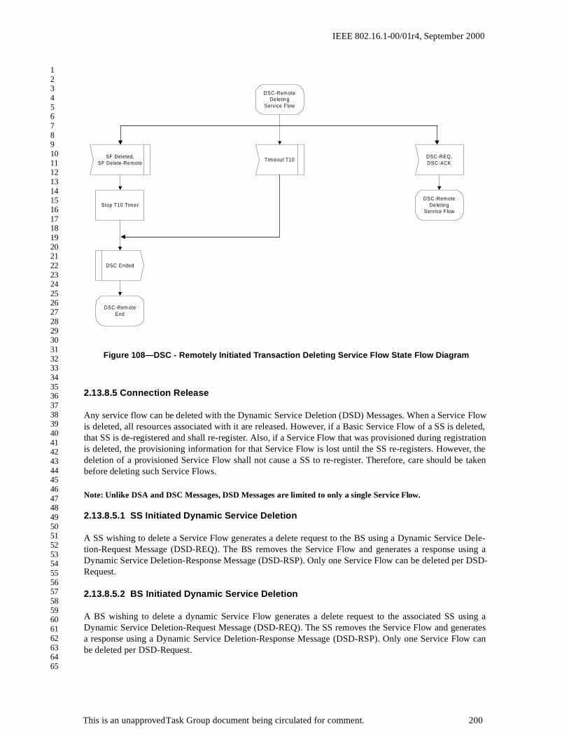
IEEE 802.16.1-00/01r4, September 2000
1234567891011121314151617181920212223242526272829303132333435363738394041424344454647484950515253545556575859606162636465
2.13.8.5 Connection Release
Any service flow can be deleted with the Dynamic Service Deletion (DSD) Messages. When a Service Flowis deleted, all resources associated with it are released. However, if a Basic Service Flow of a SS is deleted,that SS is de-registered and shall re-register. Also, if a Service Flow that was provisioned during registrationis deleted, the provisioning information for that Service Flow is lost until the SS re-registers. However, thedeletion of a provisioned Service Flow shall not cause a SS to re-register. Therefore, care should be takenbefore deleting such Service Flows.
Note: Unlike DSA and DSC Messages, DSD Messages are limited to only a single Service Flow.
2.13.8.5.1 SS Initiated Dynamic Service Deletion
A SS wishing to delete a Service Flow generates a delete request to the BS using a Dynamic Service Dele-tion-Request Message (DSD-REQ). The BS removes the Service Flow and generates a response using aDynamic Service Deletion-Response Message (DSD-RSP). Only one Service Flow can be deleted per DSD-Request.
2.13.8.5.2 BS Initiated Dynamic Service Deletion
A BS wishing to delete a dynamic Service Flow generates a delete request to the associated SS using aDynamic Service Deletion-Request Message (DSD-REQ). The SS removes the Service Flow and generatesa response using a Dynamic Service Deletion-Response Message (DSD-RSP). Only one Service Flow canbe deleted per DSD-Request.
Figure 108—DSC - Remotely Initiated Transaction Deleting Service Flow State Flow Diagram
DSC-Rem oteDeleting
Service Flow
Tim eout T10SF Deleted,
SF Delete-Remote
Stop T10 Timer
DSC Ended
DSC-Rem oteEnd
DSC-REQ,DSC-ACK
DSC-Rem oteDeleting
Service Flow
This is an unapproved Task Group document being circulated for comment. 200

IEEE 802.16.1-00/01r4, September 2000
1234567891011121314151617181920212223242526272829303132333435363738394041424344454647484950515253545556575859606162636465
Table 34: Dynamic Service Deletion Initiated from SS
SS BS
Service Flow no longer needed
Delete Service Flow
Send DSD-REQ ---DSD-REQ--> Receive DSD-REQ
Verify SS is Service Flow ‘owner’
Delete Service Flow
Receive DSD-RSP <--DSD-RSP--- Send DSD-RSP
Table 35: Dynamic Service Deletion Initiated from BS
SS BS
Service Flow no longer needed
Delete Service Flow
Determine associated SS for this Service Flow
Receive DSD-REQ <---DSD-REQ--- Send DSD-REQ
Delete Service Flow
Send DSD-RSP ---DSD-RSP--> Receive DSD-RSP
This is an unapproved Task Group document being circulated for comment. 201

IEEE 802.16.1-00/01r4, September 2000
1234567891011121314151617181920212223242526272829303132333435363738394041424344454647484950515253545556575859606162636465
2.13.8.5.3 Dynamic Service Deletion State Transition Diagrams
Figure 109—DSD - Locally Initiated Transaction Begin State Flow Diagram
SF Delete
DSD-LocalBegin
DSD-LocalDSD-R SPPending
Set D SD -REQRetries Availableto 'DSx R equest
Retries'
DSD-R EQ
Start T7 T im er
Save transm ittedDSD-R EQ
Disableservice flow
This is an unapproved Task Group document being circulated for comment. 202

IEEE 802.16.1-00/01r4, September 2000
1234567891011121314151617181920212223242526272829303132333435363738394041424344454647484950515253545556575859606162636465
Figure 110—DSD - Locally Initiated Transaction DSD-RSP Pending State Flow Diagram
DS D-LocalDS D-RS PP ending
DS D-RS PS F Delete-Rem ote
DS D-LocalHolding Down
S tart T7 T im er
S top T7 T im er S top T7 T im er
DS DS ucceeded
S F DS D-RE QLost
RetriesA vailab le
?
Y es
S avedDS D-RE Q
Tim eout T 7
RetriesA vailab le
?
Y es
DS D E rred
DS D E nded
DS D-LocalE nd
DS D-LocalDS D-RS PP ending
Decrem entDS D-RE Q
Retries A vailab le
S avedDS D-RE Q
S tart T 7 Tim er
No
No
This is an unapproved Task Group document being circulated for comment. 203
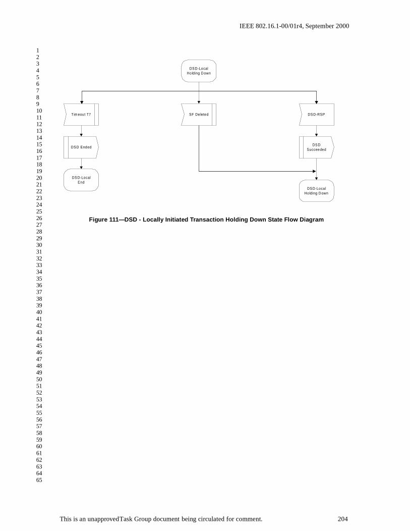
IEEE 802.16.1-00/01r4, September 2000
1234567891011121314151617181920212223242526272829303132333435363738394041424344454647484950515253545556575859606162636465
Figure 111—DSD - Locally Initiated Transaction Holding Down State Flow Diagram
DS D-LocalHolding Down
DS D-RSP
DS DSucceeded
DS D-LocalHolding Down
SF DeletedTim eout T7
DS D Ended
DS D-LocalEnd
This is an unapproved Task Group document being circulated for comment. 204

IEEE 802.16.1-00/01r4, September 2000
1234567891011121314151617181920212223242526272829303132333435363738394041424344454647484950515253545556575859606162636465
2.14 Authentication and Privacy
2.14.1 Privacy Overview
Privacy provides subscribers with privacy across the fixed broadband wireless network. It does this byencrypting connectionss between SS and BS.
In addition, Privacy provides operators with strong protection from theft of service. The BS protects againstunauthorized access to these data transport services by enforcing encryption of the associated traffic flowsacross the network. Privacy employs an authenticated client/server key management protocol in which the
Figure 112—DSD - Remotely Initiated Transaction Begin State Flow Diagram
D S D -R em oteB eg in
S ta rt T10 T im er
S ave transm ittedD S D -R S P
D S D -R em oteH o ld ing D ow n
D isab leserv ice f low
D S D -R E Q
D S D -R S P
D S DS ucceeded
This is an unapproved Task Group document being circulated for comment. 205

IEEE 802.16.1-00/01r4, September 2000
1234567891011121314151617181920212223242526272829303132333435363738394041424344454647484950515253545556575859606162636465
BS, the server, controls distribution of keying material to client SS. Additionally, the basic privacy mecha-nisms are strengthened by adding digital-certificate based SS authentication to its key management protocol.
2.14.2 Architectural Overview
Privacy has two component protocols:
An encapsulation protocol for encrypting packet data across the fixed broadband wireless access network.This protocol defines (1) a set of supported cryptographic suites, i.e., pairings of data encryption andauthentication algorithms, and (2) the rules for applying those algorithms to a MAC header’s pay-load.
A key management protocol (Privacy Key Management, or “PKM”) providing the secure distribution ofkeying data from BS to SS. Through this key management protocol, SS and BS synchronize keyingdata; in addition, the BS uses the protocol to enforce conditional access to network services.
2.14.2.1 Packet Data Encryption
Encryption services are defined as a set of capabilities within the MAC sublayer. MAC Header informationspecific to encryption is allocated in the Generic MAC Header Formant.
This specification supports a single packet date encryption algorithm: the Cipher Block Chaining (CBC)mode of the US Data Encryption Standard (DES) algorithm [FIPS-46-1] [FIPS-81]. It does not pair DESCBC with any packet data authentication algorithm. Additional data encryption algorithms may be sup-ported in future enhancements to the protocol specification, and these algorithms may be paired with dataauthentication algorithms.
Encryption is always applied to the MAC PDU payload; the Generic MAC Header is not encrypted. AllMAC management messages shall be sent in the clear to facilitate registration, ranging, and normal opera-tion of the MAC sublayer.
Section 2.15 specifies the format of MAC PDUs carrying encrypted packet data payloads.
2.14.2.2 Key Management Protocol
SS use the Privacy Key Management protocol to obtain authorization and traffic keying material from theBS, and to support periodic reauthorization and key refresh. The key management protocol uses X.509 digi-tal certificates [ITU1], RSA [RSA, RSA1, RSA3] (a public-key encryption algorithm) and two-key tripleDES to secure key exchanges between SS and BS.
The Privacy Key Management protocol adheres to a client/server model, where the SS, a PKM “client”,requests keying material, and the BS, a PKM “server”, responds to those requests, ensuring individual SSclients only receive keying material they are authorized for. The PKM protocol uses MAC management mes-saging.
Privacy uses public-key cryptography to establish a shared secret (i.e., an Authorization Key) between SSand BS. The shared secret is then used to secure subsequent PKM exchanges of traffic encryption keys. Thistwo-tiered mechanism for key distribution permits refreshing of traffic encryption keys without incurring theoverhead of computation-intensive public-key operations.
A BS authenticates a client SS during the initial authorization exchange. Each SS carries a unique X.509digital certificate issued by the SS’s manufacturer. The digital certificate contains the SS’s Public Key alongwith other identifying information; i.e., SS MAC address, manufacturer ID and serial number. Whenrequesting an Authorization Key, a SS presents it’s digital certificate to a BS. The BS verifies the digital cer-
This is an unapproved Task Group document being circulated for comment. 206

IEEE 802.16.1-00/01r4, September 2000
1234567891011121314151617181920212223242526272829303132333435363738394041424344454647484950515253545556575859606162636465
tificate, and then uses the verified Public Key to encrypt an Authorization Key, which the BS then sends backto the requesting SS.
The BS associates a SS’s authenticated identity to a paying subscriber, and hence to the data services thatsubscriber is authorized to access. Thus, with the Authorization Key exchange, the BS establishes an authen-ticated identity of a client SS, and the services (i.e., specific traffic encryption keys) the SS is authorized toaccess.
Since the BS authenticates SS, it can protect against an attacker employing a cloned SS, masquerading as alegitimate subscriber’s SS. The use of the X.509 certificates prevents cloned SSs from passing fake creden-tials onto a BS.
SS shall have factory-installed RSA private/public key pairs or provide an internal algorithm to generatesuch key pairs dynamically. If a SS relies on an internal algorithm to generate its RSA key pair, the SS shallgenerate the key pair prior to its first Privacy initialization, described in Section 2.14.3.1. SS with factory-installed RSA key pairs shall also have factory-installed X.509 certificates. SS that rely on internal algo-rithms to generate an RSA key pair shall support a mechanism for installing a manufacturer-issued X.509certificate following key generation.
The PKM protocol is defined in detail in Section 2.16.
2.14.2.3 Security Associations
A Security Association (SA) is the set of security information a BS and one or more of its client SS share inorder to support secure communications across the BWA network. Three types of Security Associations aredefined: Primary, Static, and Dynamic. A Primary Security Association is related to the Basic CID that everySS establishes during registration. Static Security Associations are provisioned within the BS. DynamicSecurity Associations are established and eliminated, on the fly, in response to the initiation and terminationof specific traffic flows. Both Static and Dynamic SAs can by shared by multiple SS.
A Security Association’s shared information includes traffic encryption keys and CBC initialization vectors.In order to support, in future protocol enhancements, alternative data encryption and data authenticationalgorithms, Security Association parameters include a cryptographic suite identifier, indicating a the particu-lar pairing of packet data encryption and packet data authentication algorithms employed by the securityassociation. At the time of release of this specification, 56-bit DES is the only packet data encryption algo-rithms supported, and neither are paired with a PDU authentication algorithm.
Security Associations are identified using a SAID.
Each (Privacy enabled) SS establishes an exclusive Primary Security Association with its BS. All of a SS’supstream traffic, and typically all downstream unicast traffic directed at SS device(s) behind the SS, areencrypted under the SS’s exclusive, Primary Security Association. (Selected downstream unicast trafficflows may be encrypted under Static or Dynamic SAs.) The CID corresponding to a SS’s Primary SA shallbe equal to the SS’s Basic CID. Downstream traffic may be encrypted under any of the three types of SAs. Adownstream multicast PDU, however, is typically intended for multiple SS and hence is more likely to beencrypted under Static or Dynamic SAs, which multiple SS can access, as opposed to a Primary SA, whichis restricted to a single SS.
Using the PKM protocol, a SS requests from its BS a SA’s keying material. The BS ensures that each clientSS only has access to the Security Associations it is authorized to access.
A SA's keying material (e.g., DES key and CBC Initialization Vector) has a limited lifetime. When the BSdelivers SA keying material to a SS, it also provides the SS with that material's remaining lifetime. It is theresponsibility of the SS to request new keying material from the BS before the set of keying material that the
This is an unapproved Task Group document being circulated for comment. 207

IEEE 802.16.1-00/01r4, September 2000
1234567891011121314151617181920212223242526272829303132333435363738394041424344454647484950515253545556575859606162636465
SS currently holds expires at the BS. The PKM protocol specifies how SS and BS maintain key synchroniza-tion.
2.14.3 Operational Overview
2.14.3.1 SS Initialization
SS initialization is divided into the following sequence of tasks:
scan for downstream channel and establish synchronization with the BSobtain transmit parameters perform rangingestablish IP connectivity (DHCP)establish time of daytransfer operational parameters (download parameter file via TFTP)BS Registration
Privacy establishment follows BS registration.
If a SS is to run Privacy, its parameter file, downloaded during the transfer of operational parameters, shallinclude Privacy Configuration Settings. These additional configuration settings are defined in <TBD>.
Upon completing BS registration, the BS will have assigned one or more static CIDs to the registering SSthat match the SS’s static class-of-service provisioning. The first static CID assigned during the registrationprocess is the Basic CID, and this CID will also serve as the SS’s Privacy Basic SAID. If a SS is configuredto run Privacy, BS registration is immediately followed by initialization of the SS’s Privacy security func-tions.
Privacy initialization begins with the SS sending the BS an Authorization Request, containing:
data identifying the SS (e.g., MAC address), the SS’s RSA public key, an X.509 certificate verifying the binding between the SS’s identifying data and the SS’s public key, a list of the SS’s security capabilities (i.e., the particular pairings of encryption and authentication algo-
rithms the SS supports) and the SS’s Primary SAID.
If the BS determines the requesting SS is authorized for the Authorization Request’s Basic SAID, the BSresponds with an Authorization Reply containing an Authorization Key, from which SS and BS derive thekeys needed to secure a SS’s subsequent requests for traffic encryption keys and the BS’s responses to theserequests. The BS encrypts the Authorization Key with the receiving SS’s public key.
The Authorization Reply also contains a list of security association descriptors, identifying the primary andstatic SAs the requesting SS is authorized to access. Each SA descriptor consists of a collection of SAparameters, including the SA’s SAID, type and cryptographic. The list contains at least one entry: a descrip-tor describing the SS’s primary security association. Additional entries are optional, and would describe anystatic SAs the SS was provisioned to access.
After successfully completing authentication and authorization with the BS, the SS sends key requests to theBS, requesting traffic encryption keys to use with each of its SAIDs. A SS’s traffic key requests are authenti-cated using a keyed hash (the HMAC algorithm [RFC-2104]); the Message Authentication Key is derivedfrom the Authorization Key obtained during the earlier authorization exchange. The BS responds with keyreplies, containing the Traffic Encryption Keys (TEKs); TEKs are triple DES encrypted with a key encryp-
This is an unapproved Task Group document being circulated for comment. 208

IEEE 802.16.1-00/01r4, September 2000
1234567891011121314151617181920212223242526272829303132333435363738394041424344454647484950515253545556575859606162636465
tion key derived from the Authorization Key. Like the Key Requests, Key Replies are authenticated with akeyed hash, where the Message Authentication Key is derived from the Authorization Key.
2.14.3.2 SS Key Update Mechanism
The traffic encryption keys which the BS provides to client SS have a limited lifetime. The BS delivers akey’s remaining lifetime, along with the key value, in the key replies it sends to its client SS. The BS controlswhich keys are current by flushing expired keys and generating new keys. It is the responsibility of individ-ual SSs to insure the keys they are using match those the BS is using. SS do this by tracking when a particu-lar SAID’s key is scheduled to expire and issuing a new key request for the latest key prior to that expirationtime.
In addition, SSs are required to periodically reauthorize with the BS; as is the case with Traffic EncryptionKeys, an Authorization Key has a finite lifetime which the BS provides the SS along with the key value. It isthe responsibility of each SS to reauthorize and obtain a fresh Authorization Key (and an up-to-date list ofSA descriptors) before the BS expires the SS’s current Authorization Key.
Privacy initialization and key update is implemented within the Privacy Key Management protocol, definedin detail in Section 2.16.
2.15 MAC PDU Formats
When operating with Privacy enabled, SS and BS encrypt the payload regions of particular MAC PDUs theytransmit onto the FBWA network.
The Generic MAC header shall not be encrypted. The Header contains all the Encryption information(Encryption Control Field, Encryption Key Sequence Field, and CID) needed to decrypt a Payload at thereceiving station.
Four bits of a MAC Header contains a key sequence number. Recall that the keying material associated witha SA has a limited lifetime, and the BS periodically refreshes a SA’s keying material. The BS manages a 4-bit key sequence number independently for each SA and distributes this key sequence number along with theSA’s keying material to client SS. The BS increments the key sequence number with each new generation ofkeying material. The MAC Header includes this sequence number, along with the SAID, to identify the spe-cific generation of that SA keying material being used to encrypt the attached payload. Being a 4-bit quan-tity, the sequence number wraps around to 0 when it reaches 15.
Figure 113—MAC PDU Encryption
Generic MAC Header Payload (optional)
Encrypted portion of the MAC PDU
This is an unapproved Task Group document being circulated for comment. 209

IEEE 802.16.1-00/01r4, September 2000
1234567891011121314151617181920212223242526272829303132333435363738394041424344454647484950515253545556575859606162636465
Comparing a received PDU’s key sequence number with what it believes to be the “current” key sequencenumber, a SS or BS can easily recognize a loss of key synchronization with its peer. A SS shall maintain thetwo most recent generations of keying material for each SA. Keeping on-hand the two most recent key gen-erations is necessary for maintaining uninterrupted service during a SA’s key transition.
Encryption of the payload is indicated by the Encryption Control (EC) bit field. A value of 0 indicates thepayload is encrypted and the EKS field contains meaningful data. A value of 1 indicates the payload is notencrypted and the EKS field is set to all zeros.
2.15.1 Fragmentation and Encryption
A fragment may have its payload encrypted. Encryption is applied after fragmentation. Likewise, decryptionis applied before reassembly of the PDU fragments.
2.16 Privacy Key Management (PKM) Protocol
2.16.1 State Models
2.16.1.1 Introduction
The PKM protocol is specified by two separate, but interdependent, state models: an authorization statemodel (the Authorization state machine) and an operational service key state model (the Traffic EncryptionKey, or TEK state machine). This section defines these two state models. The state models are for explana-tory purposes only, and should not be construed as constraining an actual implementation.
SS authorization, controlled by the Authorization state machine, is the process of:
the BS authenticating a client SS’s identitythe BS providing the authenticated SS with an Authorization Key, from which a Key Encryption Key
(KEK) and message authentication keys are derivedthe BS providing the authenticated SS with the identities (i.e., the SAIDs) and properties of primary and
static security associations the SS is authorized to obtain keying information for
The KEK is a two-key triple DES encryption key that the BS uses to encrypt the Traffic Encryption Keys(TEKs) it sends to the SS. Traffic encryption keys are used for encrypting user data traffic. SS and BS usemessage authentication keys to authenticate, via a keyed message digest, the key requests and responses theyexchange.
After achieving initial authorization, a SS periodically seeks re-authorization with the BS; reauthorization isalso managed by the SS's Authorization state machine. A SS must maintain its authorization status with theBS in order to be able to refresh aging Traffic Encryption Keys. TEK state machines manage the refreshingof Traffic Encryption Keys.
A SS begins authorization by sending an Authentication Information message to its BS. The AuthenticationInformation message contains the SS manufacturer’s X.509 certificate, issued by an external authority. TheAuthentication Information message is strictly informative, i.e., the BS may choose to ignore it; however itdoes provide a mechanism for a BS to learn the manufacturer certificates of its client SS.
The SS sends an Authorization Request message to its BS immediately after sending the AuthenticationInformation message. This is a request for an Authorization Key, as well as for the SAIDs identifying anyStatic Security Associations the SS is authorized to participate in. The Authorization Request includes:
the SS’s manufacturer ID and serial number
This is an unapproved Task Group document being circulated for comment. 210

IEEE 802.16.1-00/01r4, September 2000
1234567891011121314151617181920212223242526272829303132333435363738394041424344454647484950515253545556575859606162636465
the SS’s MAC address the SS's public key a manufacturer-issued X.509 certificate binding the SS’s public key to its other identifying informationa description of the cryptographic algorithms the requesting SS supports; a SS’s cryptographic capabilities
is presented to the BS as a list of cryptographic suite identifiers, each indicating a particular pairingof packet data encryption and packet data authentication algorithms the SS supports
the SS’s Basic CID. The Basic CID is the first static CID the BS assigns to a SS during RF MAC registra-tion -- the primary SAID is equal to the Basic CID
In response to an Authorization Request message, a BS validates the requesting SS’s identity, determines theencryption algorithm and protocol support it shares with the SS, activates an Authorization Key for the SS,encrypts it with the SS's public key, and sends it back to the SS in an Authorization Reply message. Theauthorization reply includes:
an Authorization Key encrypted with the SS's public keya 4-bit key sequence number, used to distinguish between successive generations of Authorization Keys a key lifetimethe identities (i.e., the SAIDs) and properties of the single primary and zero or more static security associ-
ations the SS is authorized to obtain keying information for
While the Authorization Reply may identify Static SAs in addition to the Primary SA whose SAID matchesthe requesting SS’s Basic CID, the Authorization Reply shall not identify any Dynamic SAs.
The BS, in responding to a SS’s Authorization Request, will determine whether the re-questing SS, whoseidentity can be verified via the X.509 digital certificate, is authorized for basic unicast services, and whatadditional statically provisioned services (i.e., Static SAIDs) the SS's user has subscribed for. Note that theprotected services a BS makes available to a client SS can depend upon the particular cryptographic suitesSS and BS share support for.
Upon achieving authorization, a SS starts a separate TEK state machine for each of the SAIDs identified inthe Authorization Reply message. Each TEK state machine operating within the SS is responsible for man-aging the keying material associated with its respective SAID. TEK state machines periodically send KeyRequest messages to the BS, requesting a refresh of keying material for their respective SAIDs. A KeyRequest includes:
identifying information unique to the SS, consisting of the manufacturer ID, serial number, MAC addressand RSA Public Key
the SAID whose keying material is being requestedan HMAC keyed message digest, authenticating the Key Request
The BS responds to a Key Request with a Key Reply message, containing the BS’s active keying material fora specific SAID. This keying material includes:
the triple-DES-encrypted traffic encryption keyCBC initialization vectora key sequence number a key’s remaining lifetimean HMAC keyed message, authenticating the Key Reply
The traffic encryption key (TEK) in the Key Reply is triple DES (encrypt-decrypt-encrypt or EDE mode)encrypted, using a two-key, triple DES key encryption key (KEK) derived from the Authorization Key.
This is an unapproved Task Group document being circulated for comment. 211

IEEE 802.16.1-00/01r4, September 2000
1234567891011121314151617181920212223242526272829303132333435363738394041424344454647484950515253545556575859606162636465
Note that at all times the BS maintains two active sets of keying material per SAID. The lifetimes of the twogenerations overlap such that each generation becomes active halfway through the life of it predecessor andexpires halfway through the life of its successor. A BS includes in its Key Replies both of a SAID’s activegenerations of keying material.
The Key Reply provides the requesting SS, in addition to the TEK and CBC initialization vector, the remain-ing lifetime of each of the two sets of keying material. The receiving SS uses these remaining lifetimes toestimate when the BS will invalidate a particular TEK, and therefore when to schedule future Key Requestssuch that the SS requests and receives new keying material before the BS expires the keying material the SScurrently holds.
The operation of the TEK state machine’s Key Request scheduling algorithm, combined with the BS’s regi-men for updating and using a SAID’s keying material (see Section 2.18), insures that the SS will be able tocontinually exchange encrypted traffic with the BS.
A SS shall periodically refresh its Authorization Key by re-issuing an Authorization Request to the BS.Reauthorization is identical to authorization with the exception that the SS does not send AuthenticationInformation messages during reauthorization cycles. Section 2.16.1.2’s description of the authorization statemachine clearly indicates when Authentication Information messages are sent.
To avoid service interruptions during reauthorization, successive generations of the SS’s Authorization Keyshave overlapping lifetimes. Both SS and BS shall be able to support up to two simultaneously active Autho-rization Keys during these transition periods. The operation of the Authorization state machine’s Authoriza-tion Request scheduling algorithm, combined with the BS’s regimen for updating and using a client SS’sAuthorization Keys (see Section 2.18), insures that SS will be able to refresh TEK keying information with-out interruption over the course of the SS’s reauthorization periods.
A TEK state machine remains active as long as:
the SS is authorized to operate in the BS’s security domain; i.e., it has a valid Authorization Key, andthe SS is authorized to participate in that particular Security Association; i.e. BS continues to provide
fresh keying material during re-key cycles.
The parent Authorization state machine stops all of its child TEK state machines when the SS receives fromthe BS an Authorization Reject during a reauthorization cycle. Individual TEK state machines can be startedor stopped during a reauthorization cycle if a SS’s Static SAID authorizations changed between successivere-authorizations.
Communication between Authorization and TEK state machines occurs through the passing of events andprotocol messaging. The Authorization state machine generates events (i.e., Stop, Authorized, AuthorizationPending, and Authorization Complete events) that are targeted at its child TEK state machines. TEK statemachines do not target events at their parent Authorization state machine. The TEK state machine affects theAuthorization state machine indirectly through the messaging a BS sends in response to a SS’s requests: aBS may respond to a TEK machine’s Key Requests with a failure response (i.e., Authorization Invalid mes-sage) that will be handled by the Authorization state machine.
2.16.1.1.1 Preliminary Comment on Dynamic Security Associations and Dynamic SA Map-ping
Section 2.14.2.3 introduced Dynamic SAs and mentioned how a BS can establish or eliminate a DynamicSA in response to the initiation or termination of downstream traffic flows (e.g., a particular multicastgroup’s traffic). In order for a SS to run a TEK state machine to obtain a Dynamic Security Association’skeying material, the SS needs to know the corresponding SAID value. The BS, however, does not volunteer
This is an unapproved Task Group document being circulated for comment. 212

IEEE 802.16.1-00/01r4, September 2000
1234567891011121314151617181920212223242526272829303132333435363738394041424344454647484950515253545556575859606162636465
to client SS the existence of Dynamic SAs; instead, it is the responsibility of SS to request of the BS themappings of traffic flow identifiers (e.g., an multicast address) to dynamic SAIDs.
The protocol defines a messaging exchange by which a SS learns the mapping of a downstream traffic flowto a Dynamic SA (all upstream traffic is encrypted under a SS’s Primary SA). A SA Mapping state machinespecifies how SSs manage the transmission of these mapping request messages. This is a forward-lookingdefinition designed to support multicast traffic encryption.
The Authorization state machine controls the establishment and termination of TEK state machines associ-ated with the Primary and any Static SAs; it does not, however, control the establishment and termination ofTEK state machines associated with Dynamic SAs. SS shall implement the necessary logic to establish andterminate a Dynamic SA’s TEK state machine. This interface specification, however, does not specify howSS should manage their Dynamic SA’s TEK state machines.
A full description of the SA Mapping state model is deferred to Section 2.17.
2.16.1.1.2 Security Capabilities Selection
As part of their authorization exchange, the SS provides the BS with a list of all the cryptographic suites(pairing of data encryption and data authentication algorithms) the SS supports. The BS selects from this lista single cryptographic suite to employ with the requesting SS’s primarySA. The Authorization Reply the BSsends back to the SS includes a primary SA descriptor which, among other things, identifies the crypto-graphic suite the BS selected to use for the SS’s primary SA. A BS shall reject the authorization request if itdetermines that none of the offered cryptographic suites are satisfactory.
The Authorization Reply also contains an optional list of static SA descriptors; each static SA descriptoridentifies the cryptographic suite employed within the SA. The selection of a static SA’s cryptographic suiteis typically made independent of the requesting SS’s cryptographic capabilities. A BS may include in itsAuthorization Reply static SA descriptors identifying cryptographic suites the requesting SS does not sup-port; if this is the case, the SS shall not start TEK state machines for static SAs whose cryptographic suitesthe SS does not support.
The above selection framework was incorporated in order to support future enhancements to MAC hardwareand to the Privacy protocol. At the time of release of this specification, 56-bit DES and 40-bit DES are theonly packet data encryption algorithms supported, and neither are paired with a packet data authenticationalgorithm.
2.16.1.2 Authorization State Machine
The Authorization state machine consists of six states and eight distinct events (including receipt of mes-sages) that can trigger state transitions. The Authorization finite state machine (FSM) is presented below in agraphical format, as a state flow model (Figure 114), and in a tabular format, as a state transition matrix(Table 36).
The state flow diagram depicts the protocol messages transmitted and internal events generated for each ofthe model’s state transitions; however, the diagram does not indicate additional internal actions, such as theclearing or starting of timers, that accompany the specific state transitions. Accompanying the state transi-tion matrix is a detailed description of the specific actions accompanying each state transition; the state tran-sition matrix shall be used as the definitive specification of protocol actions associated with each statetransition.
The following legend applies to the Authorization State Machine flow diagram in depicted in Figure 114.
Ovals are states.
This is an unapproved Task Group document being circulated for comment. 213

IEEE 802.16.1-00/01r4, September 2000
1234567891011121314151617181920212223242526272829303132333435363738394041424344454647484950515253545556575859606162636465
Events are in italics.Messages are in normal font.State transitions (i.e. the lines between states) are labeled with <what causes the transition>/<messages
and events triggered by the transition>. So “timeout/Auth Request” means that the state received a“timeout” event and sent an Authorization Request (“Auth Request”) message. If there are multipleevents or messages before the slash “/” separated by a comma, any of them can cause a transition. Ifthere are multiple events or messages listed after the slash, all of the specified actions must accom-pany the transition.
The Authorization state transition matrix presented in Table 36 lists the six Authorization machine states inthe top-most row and the eight Authorization machine events (includes message receipts) in the left-mostcolumn. Any cell within the matrix represents a specific combination of state and event, with the next state(the state transitioned to) displayed within the cell. For example, cell 4-B represents the receipt of an Autho-rization Reply (Auth Reply) message when in the Authorize Wait (Auth Wait) state. Within cell 4-B is thename of the next state, “Authorized.” Thus, when a SS’s Authorization state machine is in the AuthorizeWait state and an Authorization Reply message is received, the Authorization state machine will transition tothe Authorized state. In conjunction with this state transition, several protocol actions must be taken; theseare described in the listing of protocol actions, under the heading 4-B, in Section 2.16.1.2.5.
A shaded cell within the state transition matrix implies that either the specific event cannot or should notoccur within that state, and if the event does occur, the state machine shall ignore it. For example, if anAuthorization Reply message arrives when in the Authorized state, that message should be ignored (cell 4-C). The SS may, however, in response to an improper event, log its occurrence, generate an SNMP event, ortake some other vendor-defined action. These actions, however, are not specified within the context of theAuthorization state machine, which simply ignores improper events.
Figure 114—Authorization State Machine Flow Diagram
This is an unapproved Task Group document being circulated for comment. 214

IEEE 802.16.1-00/01r4, September 2000
1234567891011121314151617181920212223242526272829303132333435363738394041424344454647484950515253545556575859606162636465
Table 36— Authorization FSM State Transition Matrix
2.16.1.2.1 States
Start
This is the initial state of the FSM. No resources are assigned to or used by the FSM in this state—e.g., alltimers are off, and no processing is scheduled.
Authorize Wait (Auth Wait)
The SS has received the “Provisioned” event indicating that it has completed RF MAC registration with theBS. In response to receiving the event, the SS has sent both an Authentication Information and an AuthorizeRequest message to the BS and is waiting for the reply.
Authorized
The SS has received an Authorization Reply message which contains a list of valid SAIDs for this SS. Atthis point, the SS has a valid Authorization Key and SAID list. Transition into this state triggers the creationof one TEK FSM for each of the SS’s privacy-enabled SAIDs.
Reauthorize Wait (Reauth Wait)
State
Event or Rcvd
Message
(A)
Start
(B)
Auth Wait
(C)
Authorized
(D)
Reauth Wait
(E)
Auth
Reject
Wait
(F)
Silent
(1)
Provisioned
Auth Wait
(2)
Auth Reject
Auth
Reject
Wait
Auth
Reject
Wait(3)
Perm Auth Reject
Silent Silent
(4)
Auth Reply
Authorized Authorized
(5)
Timeout
Auth Wait Reauth Wait
Start
(6)
Auth Grace Timeout
Reauth Wait
(7)
Auth Invalid
Reauth Wait
Reauth Wait
(8)
Reauth
Reauth Wait
This is an unapproved Task Group document being circulated for comment. 215

IEEE 802.16.1-00/01r4, September 2000
1234567891011121314151617181920212223242526272829303132333435363738394041424344454647484950515253545556575859606162636465
The SS has an outstanding re-authorization request. The SS was either about to time out its current authori-zation or received an indication (an Authorization Invalid message from the BS) that it’s authorization wasno longer valid. The SS sent an Authorization Request message to the BS and is waiting for a response.
Authorize Reject Wait (Auth Reject Wait)
The SS received an Authorization Reject message in response to its last Authorization Request. The Autho-rization Reject’s error code indicated the error was not of a permanent nature. In response to receiving thisreject message, the SS set a timer and transitioned to the Authorize Reject Wait state. The SS remains in thisstate until the timer expires.
Silent
The SS received an Authorization Reject message in response to its last Authorization Request. The Autho-rization Reject’s error code indicated the error was of a permanent nature. This triggers a transition to theSilent state, where the SS is not permitted to pass Subscriber traffic, but is able to respond to SNMP manage-ment requests arriving from across the cable network.
2.16.1.2.2 Messages
Note that the message formats are defined in detail in Section 2.16.2.
Authorization Request (Auth Request)
Request an Authorization Key and list of authorized SAIDs. Sent from SS to BS.
Authorization Reply (Auth Reply)
Receive an Authorization Key and list of authorized, static SAIDs. Sent from BS to SS. The AuthorizationKey is encrypted with the SS’s public key.
Authorization Reject (Auth Reject)
Attempt to authorize was rejected. Sent from the BS to the SS.
Authorization Invalid (Auth Invalid)
The BS can send an Authorization Invalid message to a client SS as:
an unsolicited indication, ora response to a message received from that SS
In either case, the Authorization Invalid message instructs the receiving SS to re-authorize with its BS.
The BS responds to a Key Request with an Authorization Invalid message if (1) the BS does not recognizethe SS as being authorized (i.e., no valid Authorization Key associated with SS) or (2) verification of the KeyRequest’s keyed message digest (in HMAC-Digest Attribute) failed. Note that the Authorization Invalidevent, referenced in both the state flow diagram and the state transition matrix, signifies either the receipt ofa Authorization Invalid message or an internally generated event.
Authentication Information (Authent Info)
This is an unapproved Task Group document being circulated for comment. 216

IEEE 802.16.1-00/01r4, September 2000
1234567891011121314151617181920212223242526272829303132333435363738394041424344454647484950515253545556575859606162636465
The Authentication Information message contains the SS manufacturer’s X.509 Certificate, issued by anexternal authority. The Authent Info message is strictly an informative message the SS sends to the BS; withit, a BS may dynamically learn the manufacturer certificate of client SS. Alternatively, a BS may require out-of-band configuration of its list of manufacturer certificates.
2.16.1.2.3 Events
Provisioned
The Authorization state machine generates this event upon entering the Start state if the RF MAC has com-pleted initialization, i.e., BS registration. If the RF MAC initialization is not complete, the SS sends a Provi-sioned event to the Authorization FSM upon completing BS registration. The Provisioned event triggers theSS to begin the process of getting its Authorization Key and TEKs.
Timeout
A retransmission or wait timer timed out. Generally a request is resent.
Authorization Grace Timeout (Auth Grace Timeout)
The Authorization Grace timer timed out. This timer fires a configurable amount of time (the AuthorizationGrace Time) before the current authorization is supposed to expire, signalling the SS to re-authorize beforeits authorization actually expires. The Authorization Grace Time is specified in a configuration settingwithin the TFTP-downloaded parameter file.
Reauthorize (Reauth)
SS's set of authorized static SAIDs may have changed. Event generated in response to an SNMP set, meantto trigger a reauthorization cycle.
Authorization Invalid (Auth Invalid)
This event can be internally generated by the SS when there is a failure authenticating a Key Reply or KeyReject message, or externally generated by the receipt of an Authorization Invalid message, sent from the BSto the SS. A BS responds to a Key Request with an Authorization Invalid if verification of the request’s mes-sage authentication code fails. Both cases indicate BS and SS have lost Authorization Key synchronization.
A BS may also send a SS an unsolicited Authorization Invalid message to a SS, forcing an AuthorizationInvalid event.
Permanent Authorization Reject (Perm Auth Reject)
The SS receives an Authorization Reject in response to an Authorization Request. The error code in theAuthorization Reject indicates the error is of a permanent nature. What is interpreted as a permanent error issubject to administrative control within the BS. Authorization Request processing errors that can be inter-preted as permanent error conditions include:
unknown manufacturer (do not have CA certificate of the issuer of the SS Certificate)invalid signature on SS certificateASN.1 parsing failureinconsistencies between data in the certificate and data in accompanying PKM data Attributesincompatible security capabilities
This is an unapproved Task Group document being circulated for comment. 217

IEEE 802.16.1-00/01r4, September 2000
1234567891011121314151617181920212223242526272829303132333435363738394041424344454647484950515253545556575859606162636465
When a SS receives an Authorization Reject indicating a permanent failure condition, the AuthorizationState machine moves into a Silent state where the SS is not permitted to pass Subscriber traffic, but is able torespond to SNMP management requests received across the cable network interface. SS shall issue anSNMP Trap upon entering the Silent state.
Authorization Reject (Auth Reject)
The SS receives an Authorization Reject in response to an Authorization Request. The error code in theAuthorization Reject does not indicate the failure was due to a permanent error condition. As a result, theSS’s Authorization state machine will set a wait timer and transition into the Authorization Reject WaitState. The SS remains in this state until the timer expires, at which time it will re-attempt authorization.
[Note: the following events are sent by an Authorization state machine to the TEK state machine.]
[TEK] Stop
Sent by the Authorization FSM to an active (non -START state) TEK FSM to terminate the FSM and removethe corresponding SAID’s keying material from the SS’s key table.
[TEK] Authorized
Sent by the Authorization FSM to a non-active (START state), but valid TEK FSM.
[TEK] Authorization Pending (Auth Pend)
Sent by the Authorization FSM to a specific TEK FSM to place that TEK FSM in a wait state until theAuthorization FSM can complete its re-authorization operation.
[TEK] Authorization Complete (Auth Comp)
Sent by the Authorization FSM to a TEK FSM in the Operational Reauthorize Wait (Op Reauth Wait) orRekey Reauthorize Wait (Rekey Reauth Wait) states to clear the wait state begun by a TEK FSM Authoriza-tion Pending event.
2.16.1.2.4 Parameters
All configuration parameter values are specified in the TFTP-downloaded parameter file (see 2.20: TFTPConfiguration File Extensions).
Authorize Wait Timeout (Auth Wait Timeout)
Timeout period between sending Authorization Request messages from Authorize Wait state. See 2.20.1.1.1.
Authorization Grace Time (Auth Grace Time)
Amount of time before authorization is scheduled to expire that the SS starts reauthorization. See .
Authorization Grace Time (Auth Grace Timeout)
Amount of time before authorization is scheduled to expire that the SS starts re-authorization. See2.20.1.1.2.
Authorize Reject Wait Timeout (Auth Reject Wait Timeout)
This is an unapproved Task Group document being circulated for comment. 218

IEEE 802.16.1-00/01r4, September 2000
1234567891011121314151617181920212223242526272829303132333435363738394041424344454647484950515253545556575859606162636465
Amount of time a SS’s Authorization FSM remains in the Authorize Reject Wait state before transitioning tothe Start state. See .
2.16.1.2.5 Actions
Actions taken in association with state transitions are listed by <event/rcvd message> - <state> below:
1-A Start (Provisioned) � Auth Wait
send Authentication Information message to BSsend Authorization Request message to BSset Authorization Request retry timer to Authorize Wait Timeout
2-B Auth Wait (Auth Reject) � Auth Reject Wait
clear Authorization Request retry timerset a wait timer to Authorize Reject Wait Timeout
2-D Reauth Wait (Auth Reject) � Auth Reject Wait
clear Authorization Request retry timergenerate TEK FSM Stop events for all active TEK state machinesset a wait timer to Authorize Reject Wait Timeout
3-B Auth Wait (Perm Auth Reject) � Silent
clear Authorization Request retry timerdisable all forwarding of SS traffic
3-D Reauth Wait (Perm Auth Reject) � Silent
clear Authorization Request retry timergenerate TEK FSM Stop events for all active TEK state machinesdisable all forwarding of SS traffic
4-B Auth Wait (Auth Reply) � Authorized
clear Authorization Request retry timerdecrypt and record Authorization Key delivered with Authorization Replystart TEK FSMs for all SAIDs listed in Authorization Reply (provided the SS supports the cryptographic
suite that is associated with a SAID) and issue a TEK FSM Authorized event for each of the newTEK FSMs
set the Authorization Grace timer to go off “Authorization Grace Time” seconds prior to the suppliedAuthorization Key’s scheduled expiration
4-D Reauth Wait (Auth Reply) � Authorized
clear Authorization Request retry timerdecrypt and record Authorization Key delivered with Authorization Reply
This is an unapproved Task Group document being circulated for comment. 219

IEEE 802.16.1-00/01r4, September 2000
1234567891011121314151617181920212223242526272829303132333435363738394041424344454647484950515253545556575859606162636465
start TEK FSMs for any newly authorized SAIDs listed in Authorization Reply (provided the SS supportsthe cryptographic suite that is associated with the new SAID) and issue TEK FSM Authorized eventfor each of the new TEK FSMs
generate TEK FSM Authorization Complete events for any currently active TEK FSMs whose corre-sponding SAIDs were listed in Authorization Reply
generate TEK FSM Stop events for any currently active TEK FSMs whose corresponding SAIDs were notlisted in Authorization Reply
set the Authorization Grace timer to go off “Authorization Grace Time” seconds prior to the suppliedAuthorization Key’s scheduled expiration
5-B Auth Wait (Timeout) � Auth Wait
send Authentication Information message to BSsend Authorization Request message to BSset Authorization Request retry timer to Authorize Wait Timeout
5-D Reauth Wait (Timeout) � Reauth Wait
send Authorization Request message to BSset Authorization Request retry timer to Reauthorize Wait Timeout
5-E Auth Reject Wait (Timeout) � Start
no protocol actions associated with state transition
6-C Authorized (Auth Grace Timeout) � Reauth Wait
send Authorization Request message to BSset Authorization Request retry timer to Reauthorize Wait Timeout
7-C Authorized (Auth Invalid) � Reauth Wait
clear Authorization Grace timersend Authorization Request message to BSset Authorization Request retry timer to Reauthorize Wait Timeoutif the Authorization Invalid event is associated with a particular TEK FSM, generate a TEK FSM Autho-
rization Pending event for the TEK state machine responsible for the Authorization Invalid event(i.e., the TEK FSM that either generated the event, or sent the Key Request message the BSresponded to with an Authorization Invalid message)
7-D Reauth Wait (Auth Invalid) � Reauth Wait
if the Authorization Invalid event is associated with a particular TEK FSM, generate a TEK FSM Autho-rization Pending event for the TEK state machine responsible for the Authorization Invalid event(i.e., the TEK FSM that either generated the event, or sent the Key Request message the BSresponded to with an Authorization Invalid message)
8-C Authorized (Reauth) � Reauth Wait
clear Authorization grace timersend Authorization Request message to BS
This is an unapproved Task Group document being circulated for comment. 220

IEEE 802.16.1-00/01r4, September 2000
1234567891011121314151617181920212223242526272829303132333435363738394041424344454647484950515253545556575859606162636465
set Authorization Request retry timer to Reauthorize Wait Timeout2.16.1.3 TEK State Machine
The TEK state machine consists of six states and nine events (including receipt of messages) that can triggerstate transitions. Like the Authorization state machine, the TEK state machine is presented in both a stateflow diagram and a state transition matrix. And as was the case for the Authorization state machine, the statetransition matrix shall be used as the definitive specification of protocol actions associated with each statetransition.
Shaded states in Figure 115 (Operational, Rekey Wait, and Rekey Reauthorize Wait) have valid keying mate-rial and encrypted traffic can be passed.
The Authorization state machine starts an independent TEK state machine for each of its authorized SAIDs.
As mentioned previously in Section 2.16.1.1, the BS maintains two active TEKs per SAID. The BS includesin its Key Replies both of these TEKs, along with their remaining lifetimes. The BS encrypts downstreamtraffic with the older of its two TEKs and decrypts upstream traffic with either the older or newer TEK,depending upon which of the two keys the SS was using at the time. The SS encrypts upstream traffic withthe newer of its two TEKs and decrypts downstream traffic with either the older or newer TEK, dependingupon which of the two keys the BS was using at the time. See Section 2.18 for details on SS and BS keyusage requirements.
Through operation of a TEK state machine, the SS attempts to keep its copies of a SAID’s TEKs synchro-nized with those of its BS. A TEK state machine issues Key Requests to refresh copies of its SAID’s keyingmaterial soon after the scheduled expiration time of the older of its two TEKs and before the expiration of itsnewer TEK. To accommodate for SS/BS clock skew and other system processing and transmission delays,the SS schedules its Key Requests a configurable number of seconds before the newer TEK’s estimated expi-ration in the BS. With the receipt of the Key Reply, the SS shall always update its records with the TEKParameters from both TEKs contained in the Key Reply Message. Figure 115 illustrates the SS’s schedulingof its key refreshes in conjunction with its management of a SA’s active TEKs.
This is an unapproved Task Group document being circulated for comment. 221

IEEE 802.16.1-00/01r4, September 2000
1234567891011121314151617181920212223242526272829303132333435363738394041424344454647484950515253545556575859606162636465
Figure 115—TEK State Machine Flow Diagram
Sto
p /
Sta
rt
Rek
ey R
eaut
hW
ait
Op
Wai
t
Aut
hori
zed
/K
ey R
eque
stK
ey R
ejec
t,S
top
/
Tim
eout
/
Key
Req
uest
Op
Rea
uth
Wai
t
Sto
p /
Aut
h P
end
/
Aut
h C
omp
/K
ey R
eque
st
Tek
Inv
alid
/
Ope
rati
onal
Key
Rep
ly /
Tek
Inv
alid
/K
ey R
eque
st
Sto
p /
Rek
ey W
ait
Key
Rep
ly /
TE
K R
efre
sh T
imeo
ut /
Key
Req
uest
TE
K I
nval
id /
Key
Req
uest
Tim
eout
/K
ey R
eque
stAut
h C
omp
/K
ey R
eque
st
Aut
h P
end
/
Key
Rej
ect,
Sto
p /
This is an unapproved Task Group document being circulated for comment. 222

IEEE 802.16.1-00/01r4, September 2000
1234567891011121314151617181920212223242526272829303132333435363738394041424344454647484950515253545556575859606162636465
Table 37—TEK FSM State Transition Matrix
2.16.1.3.1 States
Start
This is the initial state of the FSM. No resources are assigned to or used by the FSM in this state—e.g., alltimers are off, and no processing is scheduled.
Operational Wait (Op Wait)
The TEK state machine has sent its initial request (Key Request) for its SAID’s keying material (trafficencryption key and CBC initialization vector), and is waiting for a reply from the BS.
Operational Reauthorize Wait (Op Reauth Wait)
The wait state the TEK state machine is placed in if it does not have valid keying material while the Authori-zation state machine is in the in the middle of a reauthorization cycle.
State
Event or Rcvd
Message
(A)
Start
(B)
Op Wait
(C)
Op Reauth Wait
(D)
Op
(E)
Rekey Wait
(F)
Rekey Reauth
Wait
(1)
Stop
Start Start Start Start Start
(2)
Authorized
Op Wait
(3)
Auth Pend
Op Reauth Wait
Rekey Re-auth Wait
(4)
Auth Comp
Op Wait Rekey Wait
(5)
TEK Invalid
Op Wait Op Wait Op Reauth Wait
(6)
Timeout
Op Wait Rekey Wait
(7)
TEK Refresh Timeout
Rekey Wait
(8)
Key Reply
Operational Operational
(9)
Key Reject
Start Start
This is an unapproved Task Group document being circulated for comment. 223

IEEE 802.16.1-00/01r4, September 2000
1234567891011121314151617181920212223242526272829303132333435363738394041424344454647484950515253545556575859606162636465
Operational
The SS has valid keying material for the associated SAID.
Rekey Wait
The TEK Refresh Timer has expired and the SS has requested a key update for this SAID. Note that thenewer of its two TEKs has not expired and can still be used for both encrypting and decrypting data traffic.
Rekey Reauthorize Wait (Rekey Reauth Wait)
The wait state the TEK state machine is placed in if the TEK state machine has valid traffic keying material,has an outstanding request for the latest keying material, and the Authorization state machine initiates areauthorization cycle.
2.16.1.3.2 Messages
Note that the message formats are defined in detail in Section 2.16.2.
Key Request
Request a TEK for this SAID. Sent by the SS to the BS and authenticated with keyed message digest. Themessage authentication key is derived from the Authorization Key.
Key Reply
Response from the BS carrying the two active sets of traffic keying material for this SAID. Sent by the BS tothe SS, it includes the SAID’s traffic encryption keys, triple DES encrypted with a key encryption keyderived from the Authorization Key. The Key Reply message is authenticated with a keyed message digest;the authentication key is derived from the Authorization Key.
Key Reject
Response from the BS to the SS to indicate this SAID is no longer valid and no key will be sent. The KeyReject message is authenticated with a keyed message digest; the authentication key is derived from theAuthorization Key
TEK Invalid
The BS sends a SS this message if it determines that the SS encrypted an upstream PDU with an invalidTEK; i.e., a SAID’s TEK key sequence number, contained within the received PDU’s MAC Header, is out ofthe BS’s range of known, valid sequence numbers for that SAID.
2.16.1.3.3 Events
Stop
Sent by the Authorization FSM to an active (non-START state) TEK FSM to terminate TEK FSM andremove the corresponding SAID’s keying material from the SS’s key table. See Section .
Authorized
Sent by the Authorization FSM to a non-active (START state) TEK FSM to notify TEK FSM of successfulauthorization. See Section .
This is an unapproved Task Group document being circulated for comment. 224

IEEE 802.16.1-00/01r4, September 2000
1234567891011121314151617181920212223242526272829303132333435363738394041424344454647484950515253545556575859606162636465
Authorization Pending (Auth Pend)
Sent by the Authorization FSM to TEK FSM to place TEK FSM in a wait state while Authorization FSMcompletes re-authorization. See Section .
Authorization Complete (Auth Comp)
Sent by the Authorization FSM to a TEK FSM in the Operational Reauthorize Wait or Rekey ReauthorizeWait states to clear the wait state begun by the prior Authorization Pending event. See Section <TBD>.
TEK Invalid
This event can be triggered by either a SS’s data packet decryption logic, or by the receipt of a TEK Invalidmessage from the BS.
A SS’s data packet decryption logic triggers a TEK Invalid event if it recognizes a loss of TEK key synchro-nization between itself and the encrypting BS; i.e., a SAID’s TEK key sequence number, contained withinthe received, downstream PDU’s MAC Header, is out of the SS’s range of known sequence numbers for thatSAID.
A BS sends a SS a TEK Invalid message, triggering a TEK Invalid event within the SS, if the BS’s decryp-tion logic recognizes a loss of TEK key synchronization between itself and the SS.
Timeout
A retry timer timeout. Generally, the particular request is retransmitted.
TEK Refresh Timeout
The TEK refresh timer timed out. This timer event signals the TEK state machine to issue a new KeyRequest in order to refresh its keying material. The refresh timer is set to fire a configurable length of time(TEK Grace Time) before the expiration of the newer TEK the SS currently holds. This is configured via theBS to occur after the scheduled expiration of the older of the two TEKs.
2.16.1.3.4 Parameters
All configuration parameter values are specified in TFTP downloaded parameter file (see Section 2.20,:TFTP Configuration File Extensions).
Operational Wait Timeout
Timeout period between sending of Key Request messages from the Op Wait state. See Section 2.20.1.1.3.
Rekey Wait Timeout
Timeout period between sending of Key Request messages from the Rekey Wait state. See Section2.20.1.1.4.
TEK Grace Time
Time interval, in seconds, before the estimated expiration of a TEK that the SS starts rekeying for a newTEK.
This is an unapproved Task Group document being circulated for comment. 225

IEEE 802.16.1-00/01r4, September 2000
1234567891011121314151617181920212223242526272829303132333435363738394041424344454647484950515253545556575859606162636465
TEK Grace Time is specified in a configuration setting within the TFTP-downloaded parameter file, and isthe same across all SAIDs. See Section 2.20.1.1.5.
2.16.1.3.5 Actions
1-B Op Wait (Stop) � Start
clear Key Request retry timerterminate TEK FSM
1-C Op Reauth Wait (Stop) � Start
terminate TEK FSM
1-D Operational (Stop) � Start
clear TEK refresh timer, which is timer set to go off “Tek Grace Time” seconds prior to the TEK’s sched-uled expiration time
terminate TEK FSMremove SAID keying material from key table
1-E Rekey Wait(Stop) � Start
clear Key Request retry timerterminate TEK FSMremove SAID keying material from key table
1-F Rekey Reauth Wait(Stop) � Start
terminate TEK FSMremove SAID keying material from key table
2-A Start (Authorized) � Op Wait
send Key Request Message to BSset Key Request retry timer to Operational Wait Timeout
3-B Op Wait (Auth Pend) � Op Reauth Wait
clear Key Request retry timer
3-E Rekey Wait (Auth Pend) � Rekey Reauth Wait
clear Key Request retry timer
4-C Op Reauth Wait (Auth Comp) � Op Wait
send Key Request message to BSset Key Request retry timer to Operational Wait Timeout
4-F Rekey Reauth Wait (Auth Comp) � Rekey Wait
This is an unapproved Task Group document being circulated for comment. 226

IEEE 802.16.1-00/01r4, September 2000
1234567891011121314151617181920212223242526272829303132333435363738394041424344454647484950515253545556575859606162636465
send Key Request message to BSset Key Request retry timer to Rekey Wait Timeout
5-D Operational (TEK Invalid) � Op Wait
clear TEK refresh timersend Key Request message to BSset Key Request retry timer to Operational Wait Timeoutremove SAID keying material from key table
5-E Rekey Wait (TEK Invalid) � Op Wait
clear Key Request retry timersend Key Request message to BSset Key Request retry timer to Operational Wait Timeoutremove SAID keying material from key table
5-F Rekey Reauth Wait (TEK Invalid) � Op Reauth Wait
remove SAID keying material from key table
6-B Op Wait (Timeout) � Op Wait
send Key Request message to BSset Key Request retry timer to Operational Wait Timeout
6-E Rekey Wait (Timeout) � Rekey Wait
send Key Request message to BSset Key Request retry timer to Rekey Wait Timeout
7-D Operational (TEK Grace Timeout) � Rekey Wait
send Key Request message to BSset Key Request retry timer to Rekey Wait Timeout
8-B Op Wait (Key Reply) � Operational
(Note: Key Reply passed message authentication.)
clear Key Request retry timerprocess contents of Key Reply message and incorporate new keying material into key databaseset the TEK refresh timer to go off “TEK Grace Time” seconds prior to the key’s scheduled expiration
8-E Rekey Wait (Key Reply) � Operational
(Note: Key Reply passed message authentication.)
clear Key Request retry timerprocess contents of Key Reply message and incorporate new keying material into key databaseset the TEK refresh timer to go off “TEK Grace Time” seconds prior to the key’s scheduled expiration
This is an unapproved Task Group document being circulated for comment. 227

IEEE 802.16.1-00/01r4, September 2000
1234567891011121314151617181920212223242526272829303132333435363738394041424344454647484950515253545556575859606162636465
9-B Op Wait (Key Reject) � Start
(Note: Key Reject passed message authentication.)
clear Key Request retry timerterminate TEK FSM
9-E Rekey Wait (Key Reject) � Start
clear Key Request retry timerterminate TEK FSMremove CID keying material from key table
2.16.2 Key Management Message Formats
Privacy Key Management employs two MAC message types: PKM-REQ and PKM-RSP.
While these two MAC management message types distinguish between PKM requests (SS to BS) andresponses (BS to SS), more detailed information about message contents is encoded in the PKM messagesthemselves. This maintains a clean separation between privacy management functions and MAC bandwidthallocation, timing and synchronization.
2.16.2.1 Packet Formats
Exactly one PKM message is encapsulated in the Management Message Payload field of a MAC manage-ment message.
A summary of the PKM message format is shown below. The fields are transmitted from left to right.
0 1 2 3 0 1 2 3 4 5 6 7 8 9 0 1 2 3 4 5 6 7 8 9 0 1 2 3 4 5 6 7 8 9 0 1 +-+-+-+-+-+-+-+-+-+-+-+-+-+-+-+-+-+-+-+-+-+-+-+-+-+-+-+-+-+-+-+-+ | Code | Identifier | Length | +-+-+-+-+-+-+-+-+-+-+-+-+-+-+-+-+-+-+-+-+-+-+-+-+-+-+-+-+-+-+-+-+ | Attributes ... +-+-+-+-+-+-+-+-+-+-+-+-+-
Code
The Code field is one , and identifies the type of PKM packet. When a packet is received with an invalidCode field, it SHOULD be silently discarded.
PKM Codes (decimal) are assigned as follows:
Table 38—Privacy Key Management MAC Messages
Type Value Message Name Message Description
9 PKM-REQ Privacy Key Management Request [SS -> BS]
10 PKM-RSP Privacy Key Management Response [BS -> SS]
This is an unapproved Task Group document being circulated for comment. 228

IEEE 802.16.1-00/01r4, September 2000
1234567891011121314151617181920212223242526272829303132333435363738394041424344454647484950515253545556575859606162636465
Identifier
The Identifier field is one . A SS uses the identifier to match a BS's responses to the SS's requests.
The SS shall change (e.g., increment, wrapping around to 0 after reaching 255) the Identifier fieldwhenever it issues a new PKM message. A "new" message is an Authorization Request, KeyRequest or SA Map Request that is not a retransmission being sent in response to a Timeout event.For retransmissions, the Identifier field shall remain unchanged.
The Identifier field in Authentication Information messages, which are informative and do not effectany response messaging, may be set to zero.
The Identifier field in a BS’s PKM response message shall match the Identifier field of the PKMRequest message the BS is responding to. The Identifier field in TEK Invalid messages, which arenot sent in response to PKM requests, shall be set to zero. The Identifier field in unsolicited Authori-zation Invalid messages shall be set to zero.
On reception of a PKM response message, the SS associates the message with a particular statemachine (the Authorization state machine in the case of Authorization Replies, AuthorizationRejects, and Authorization Invalids; a particular TEK state machine in the case of Key Replies, Key
Table 39—Privacy Key Management Message Codes
Code PKM Message Type MAC Management Message Name
0-3 Reserved -
4 Auth Request PKM-REQ
5 Auth Reply PKM-RSP
6 Auth Reject PKM-RSP
7 Key Request PKM-REQ
8 Key Reply PKM-RSP
9 Key Reject PKM-RSP
10 Auth Invalid PKM-RSP
11 TEK Invalid PKM-RSP
12 Authent Info PKM-REQ
13 Map Request PKM-REQ
14 Map Reply PKM-RSP
15 Map Reject PKM-RSP
16-255 Reserved -
This is an unapproved Task Group document being circulated for comment. 229

IEEE 802.16.1-00/01r4, September 2000
1234567891011121314151617181920212223242526272829303132333435363738394041424344454647484950515253545556575859606162636465
Rejects and TEK Invalids; a particular SA Mapping state machine in the case of SA Map Repliesand SA Map Rejects).
A SS may keep track of the Identifier of its latest, pending Authorization Request. The SS maysilently discard Authorization Replies and Authorization Rejects whose Identifier fields do notmatch those of the pending requests.
A SS may keep track of the Identifier of its latest, pending Key Request. The SS may silently discardKey Replies and Key Rejects whose Identifier fields do not match those of the pending requests.
A SS may keep track of the Identifier of its latest, pending SA Map Request. The SS may silentlydiscard SA Map Replies and SA Map Rejects whose Identifier fields do not match those of the pend-ing requests.
Length
The Length field is two s. It indicates the length of the Attribute fields in s. The length field does notinclude the Code, Identifier and Length fields. s outside the range of the Length field shall be treatedas padding and ignored on reception. If the packet is shorter than the Length field indicates, itSHOULD be silently discarded. The minimum length is 0 and maximum length is 1490.
Attributes
PKM Attributes carry the specific authentication, authorization and key management dataexchanged between client and server. Each PKM packet type has its own set of required and optionalAttributes. Unless explicitly stated, there are no requirements on the ordering of attributes within aPKM message.
The end of the list of Attributes is indicated by the Length of the PKM packet.
Attributes are type/length/value (TLV) encoded, as shown below. The fields are transmitted from leftto right.
Packet formats for each of the PKM messages are described below. The descriptions list the PKM attributescontained within each PKM message type. The Attributes themselves are described in Section 2.16.2.2.Unknown attributes shall be ignored on receipt, and skipped over while scanning for recognized attributes.
The BS shall silently discard all requests that do not contain ALL required attributes. The SS shall silentlydiscard all responses that do not contain ALL required attributes.
2.16.2.1.1 Authorization Request (Auth Request)
Code: 4
Attributes:
0 1 2 3 0 1 2 3 4 5 6 7 8 9 0 1 2 3 4 5 6 7 8 9 0 1 2 3 4 5 6 7 8 9 0 1+-+-+-+-+-+-+-+-+-+-+-+-+-+-+-+-+-+-+-+-+-+-+-+-+-+-+-+-+-+-+-+-+| Type | Length | Value...+-+-+-+-+-+-+-+-+-+-+-+-+-+-+-+-+-+-+-+-+-+-+-+-+-+-+-+-+-+-+-+-+
This is an unapproved Task Group document being circulated for comment. 230

IEEE 802.16.1-00/01r4, September 2000
1234567891011121314151617181920212223242526272829303132333435363738394041424344454647484950515253545556575859606162636465
The SS-Identification attribute contains a set of data that identifies the requesting SS to the BS. Note that theBS is in all likelihood using only a single item in the SS-Identification attribute (e.g., SS MAC address) as aSS handle. While a specific item could be selected for inclusion in the Authorization Request message,including the entire SS-Identification attribute for client identification provides vendors with greater flexibil-ity in the headend’s system design.
The SS-Certificate attribute contains an X.509 SS certificate issued by the SS’s manufacturer. The SS’sX.509 certificate is a public-key certificate which binds the SS’s identifying information to it’s RSA publickey in a verifiable manner. The X.509 certificate is digitally signed by the SS’s manufacturer, and that signa-ture can be verified by a BS that knows the manufacturer’s public key. The manufacturer’s public key isplaced in an X.509 certification authority (CA) certificate, which in turn is signed by a higher level certifica-tion authority.
The Security-Capabilities attribute is a compound attribute describing the requesting SS’s security capabili-ties. This includes the data encryption algorithm(s) a SS supports and the data authentication algorithm(s)supported (of which there are currently none).
A SAID attribute contains a Privacy security association identifier, or SAID. In this case, the provided SAIDis the SS’s Basic CID, which is equal to the Basic CID assigned the to SS during MAC registration.
2.16.2.1.2 Authorization Reply (Auth Reply)
Sent by the BS to a client SS in response to an Authorization Request, the Authorization Reply message con-tains an Authorization Key, the key’s lifetime, the key’s sequence number, and a list of SA-Descriptors iden-tifying the Primary and Static Security Associations the requesting SS is authorized to access and theirparticular properties (e.g., type, cryptographic suite). The Authorization Key shall be encrypted with theSS’s public key. The SA-Descriptor list shall include a descriptor for the Basic CID reported to the BS in thecorresponding Authorization Request. The SA-Descriptor list may include descriptors of Static SAIDs theSS is authorized to access.
Code field: 5
Attributes:
2.16.2.1.3 Authorization Reject (Auth Reject)
BS responds to a SS’s authorization request with an Authorization Reject message if the BS rejects the SS’sauthorization request.
Code field: 6
Attributes:
Table 40—Authorization Request Attributes
Attribute Contents
SS-Identification contains information used to identify SS to BS
SS-Certificate contains the SS’s X.509 user certificate
Security-Capabilities describes requesting SS’s security capabilities
SAID SS’s primary SAID equal to the Basic CID
This is an unapproved Task Group document being circulated for comment. 231

IEEE 802.16.1-00/01, August 2000
1234567891011121314151617181920212223242526272829303132333435363738394041424344454647484950515253545556575859606162636465
The Error-Code and Display-String attributes describe to the requesting SS the reason for the authorizationfailure.
2.16.2.1.4 Key Request
Code: 7
Attributes:
The HMAC-Digest Attribute is a keyed message digest. The HMAC-Digest Attribute shall be the finalAttribute in the Key Request’s Attribute list. The message digest is performed over the PDU header and allof the Key Request’s Attributes, other than the HMAC-Digest, in the order in which they appear within thepacket.
Inclusion of the keyed digest allows the BS to authenticate the Key Request message. The HMAC-Digest’sauthentication key is derived from the Authorization Key. See Section 2.19, Cryptographic Methods, fordetails.
Table 41—Authorization Reply Attributes
Attribute Contents
AUTH-Key Authorization (AUTH) Key, encrypted with the target client SS’s public key
Key-Lifetime Authorization key lifetime
Key-Sequence-Number Authorization key sequence number
(one or more) SA-Descriptor
Each SA-Descriptor compound Attribute specifies a SAID and additional properties of the SA.
Table 42—Auth Rej Attributes
Attribute Contents
Error-Code Error code identifying reason for rejection of authorization request
Display-String (optional) Display String providing reason for rejection of authorization request
Table 43—Key Request Attributes
Attribute Contents
SS-Identification Contains information used to identify SS to BS
Key-Sequence-Number Authorization key sequence number
SAID Security Association ID
HMAC-Digest Keyed SHA message digest
This is an unapproved Task Group document being circulated for comment. 232

IEEE 802.16.1-00/01r4, September 2000
1234567891011121314151617181920212223242526272829303132333435363738394041424344454647484950515253545556575859606162636465
2.16.2.1.5 Key Reply
Code: 8
Attributes:
The TEK-Parameters Attribute is a compound attribute containing all of the keying material correspondingto a particular generation of a SAID's TEK. This would include the TEK, the TEK’s remaining key lifetime,its key sequence number, and the CBC initialization vector. The TEK is encrypted. See Section 2.16.2.2.13for details.
At all times the BS maintains two sets of active generations of keying material per SAID. (A set of keyingmaterial includes the a TEK and its corresponding CBC initialization vector.) One set corresponds to the“older” generation of keying material, the second set corresponds to the “newer” generation of keying mate-rial. The newer generation has a key sequence number one greater than (modulo 16) that of the older gener-ation. Section 2.18.1 specifies BS requirements for maintaining and using a SAID’s two active generationsof keying material.
The BS distributes to a client SS both generations of active keying material. Thus, the Key Reply messagecontains two TEK-Parameters Attributes, each containing the keying material for one of the SAIDs twoactive sets of keying material.
The HMAC-Digest Attribute is a keyed message digest. The HMAC-Digest Attribute shall be the finalAttribute in the Key Reply’s Attribute list. The message digest is performed over the PKM message header(starting with the PKM Code field) and all of the Key Reply’s Attributes, other than the HMAC-Digest, inthe order in which they appear within the packet.
Inclusion of the keyed digest allows the receiving client to authenticate the Key Reply message and ensureSS and BS have synchronized Authorization Keys. The HMAC-Digest’s authentication key is derived fromthe Authorization Key. See Section 2.19, Cryptographic Methods, for details.
2.16.2.1.6 Key Reject
Receipt of a Key Reject indicates the receiving client SS is no longer authorized for a particular SAID.
Code: 9
Attributes:
Table 44—Key Reply Attributes
Attribute Contents
Key-Sequence-Number Authorization key sequence number
SAID Security Association ID
TEK-Parameters “Older” generation of key parameters relevant to SAID
TEK-Parameters “Newer” generation of key parameters relevant to SAID
HMAC-Digest Keyed SHA message digest
This is an unapproved Task Group document being circulated for comment. 233

IEEE 802.16.1-00/01r4, September 2000
1234567891011121314151617181920212223242526272829303132333435363738394041424344454647484950515253545556575859606162636465
The HMAC-Digest Attribute is a keyed message digest. The HMAC-Digest Attribute shall be the finalAttribute in the Key Reject’s Attribute list. The message digest is performed over the PKM message header(starting with the PKM Code field) and all of the Key Reject’s Attributes, other than the HMAC-Digest, inthe order in which they appear within the packet.
Inclusion of the keyed digest allows the receiving client to authenticate the Key Reject message and ensureSS and BS have synchronized Authorization Keys. The HMAC-Digest’s authentication key is derived fromthe Authorization Key. See Section 2.19, Cryptographic Methods, for details.
2.16.2.1.7 Authorization Invalid
The BS can send an Authorization Invalid message to a client SS as:
an unsolicited indication, ora response to a message received from that SS
In either case, the Authorization Invalid message instructs the receiving SS to re-authorize with its BS.
The BS sends an Authorization Invalid in response to a Key Request if (1) the BS does not recognize the SSas being authorized (i.e., no valid Authorization Key associated with the requesting SS) or (2) verification ofthe Key Request’s keyed message digest (in HMAC-Digest Attribute) failed, indicating a loss of Authoriza-tion Key synchronization between SS and BS.
Code: 10
Attributes:
Table 45—Key Reject Attributes
Attribute Contents
Key-Sequence-Number Authorization key sequence number
SAID Security Association ID
Error-Code Error code identifying reason for rejection of Key Request
Display-String (optional) Display string containing reason for Key Reject
HMAC-Digest Keyed SHA message digest
Table 46—Authorization Invalid Attributes
Attribute Contents
Error-Code Error code identifying reason for Authorization Invalid
Display-String (optional) Display String describing failure condition
This is an unapproved Task Group document being circulated for comment. 234

IEEE 802.16.1-00/01r4, September 2000
1234567891011121314151617181920212223242526272829303132333435363738394041424344454647484950515253545556575859606162636465
2.16.2.1.8 TEK Invalid
The BS sends a TEK Invalid message to a client SS if the BS determines that the SS encrypted an upstreamPDU with an invalid TEK; i.e., a SAID’s TEK key sequence number, contained within the received packet’sMAC Header, is out of the BS’s range of known, valid sequence numbers for that SAID.
Code: 11
Attributes:
The HMAC-Digest Attribute is a keyed message digest. The HMAC-Digest Attribute shall be the finalAttribute in the TEK Invalid’s Attribute list. The message digest is performed over the PKM message header(starting with the PKM Code field) and all of the TEK Invalid’s Attributes, other than the HMAC-Digest, inthe order in which they appear within the packet.
Inclusion of the keyed digest allows the receiving client to authenticate the TEK Invalid message and ensureSS and BS have synchronized Authorization Keys. The HMAC-Digest’s authentication key is derived fromthe Authorization Key. See Section 2.19, Cryptographic Methods, for details.
2.16.2.1.9 Authentication Information (Authent Info)
The Authentication Info message contains a single CA-Certificate Attribute, containing an X.509 CA certif-icate for the manufacturer of the SS. The SS’s X.509 user certificate shall have been issued by the certifica-tion authority identified by the X.509 CA certificate. All X.509 CA certificates shall be issued by an externalroot certification authority.
Authentication Information messages are strictly informative: while the SS shall transmit Authent Info mes-sages as indicated by the Authentication state model (Section 2.16.1.2), the BS may ignore them.
Code: 12
Attributes:
Table 47—TEK Invalid Attributes
Attribute Contents
Key-Sequence-Number Authorization key sequence number
SAID Security Association ID
Error-Code Error code identifying reason for TEK Invalid message
Display-String (optional) Display string containing vendor-defined in-formation
HMAC-Digest Keyed SHA message digest
Table 48—Authentication Information Attributes
Attribute Contents
CA-Certificate certificate of manufacturer CA that issued SS certificate
This is an unapproved Task Group document being circulated for comment. 235

IEEE 802.16.1-00/01, August 2000
1234567891011121314151617181920212223242526272829303132333435363738394041424344454647484950515253545556575859606162636465
The CA-certificate attribute contains an X.509 CA certificate for the CA that issued the SS’s X.509 user cer-tificate. The external certification authority issues these CA-certificates to SS manufacturers.
2.16.2.1.10 SA Map Request (MAP Request)
A SS sends SA Map Requests to its BS to request the mapping of a particular downstream traffic flow to aSA. Section 2.17 describes the SA Mapping state model which uses the message.
Code: 13
Attributes:
2.16.2.1.11 SA Map Reply (Map Reply)
A BS sends an SA Map Reply as a positive response to a client SS’s SA Map Request. The SA Map Replyinforms the SS of a mapping between a queried address and a SA. Section 2.17 describes the SA Mappingstate model which uses the message.
Code: 14
Attributes:
2.16.2.1.12 SAID Map Reject (Map Reject)
A BS sends SA Map Reject as a negative response to a client SS’s SA Map Request. The SA Map Rejectinforms the SS that either (1) downstream traffic flow identified in the SA-Query Attribute is not beingencrypted or (2) the requesting SS is not authorized to receive that traffic. The contents of an error codeattribute distinguishes between the two cases. Section 2.17 describes the SA Mapping state model whichuses the message.
Code: 15
Table 49—SA Map Request Attributes
Attribute Contents
SS-Identification Contains information used to identify SS to BS
SA-Query Contains addressing information identifying the downstream traffic flow SS is request-ing an SA mapping for
Table 50—SA Map Reply Attributes
Attribute Contents
SA-Query Contains addressing information identifying the downstream traffic flow SS is requested an SA mapping for
SA-Descriptor SA-Descriptor compound Attribute specifies the mapped SA’s SAID and other proper-ties.
This is an unapproved Task Group document being circulated for comment. 236

IEEE 802.16.1-00/01r4, September 2000
1234567891011121314151617181920212223242526272829303132333435363738394041424344454647484950515253545556575859606162636465
Attributes:
2.16.2.2 PKM Attributes
A summary of the Attribute format is shown below. The fields are transmitted from left to right.
0 1 2 3 0 1 2 3 4 5 6 7 8 9 0 1 2 3 4 5 6 7 8 9 0 1 2 3 4 5 6 7 8 9 0 1 +-+-+-+-+-+-+-+-+-+-+-+-+-+-+-+-+-+-+-+-+-+-+-+-+-+-+-+-+-+-+-+-+ | Type | Length | Value... +-+-+-+-+-+-+-+-+-+-+-+-+-+-+-+-+-+-+-+-+-+-+-+-+-+-+-+-+-+-+-+-+
Type
The Type field is one . Values of the PKM Type field are specified below. Note that Type valuesbetween 0 and 127 are defined within the Privacy Specification, values between 128 and 255 arevendor-assigned Attribute Types.
A PKM server shall ignore Attributes with an unknown Type.
A PKM client shall ignore Attributes with an unknown Type.
PKM client and server (i.e., SS and BS) may log receipt of unknown attribute types.
Length
The Length field is 2 s, and indicates the length of this Attribute’s Value field, in s. The length fielddoes not include the Type and Length fields. The minimum Attribute Length is 0, the maximumLength is <TBD>.
Packets containing attributes with invalid lengths SHOULD be silently discarded.
Value
The Value field is zero or more s and contains information specific to the Attribute. The format andlength of the Value field is determined by the Type and Length fields. All multi- integer quantitiesare in network-byte order, i.e., the containing the most-significant bits is the first transmitted on thewire.
Table 51—SA MAP Reject Attributes
Attribute Contents
SA-Query Contains addressing information identifying the downstream traffic flow SS requested an SA mapping for
Error-Code Error code identifying reason for rejection of SA Map Request
Display-String (optional) Display string containing reason for Map Reject
This is an unapproved Task Group document being circulated for comment. 237

IEEE 802.16.1-00/01, August 2000
1234567891011121314151617181920212223242526272829303132333435363738394041424344454647484950515253545556575859606162636465
Table 52—PKM Attribute Types
Type BPKM Attribute
0 Reserved
1 Serial-Number
2 Manufacturer-ID
3 MAC-Address
4 RSA-Public-Key
5 SS-Identification
6 Display-String
7 AUTH-KEY
8 TEK
9 Key-Lifetime
10 Key-Sequence-Number
11 HMAC-Digest
12 SAID
13 TEK-Parameters
14 Reserved
15 CBC-IV
16 Error-Code
17 CA-Certificate
18 SS-Certificate
19 Security-Capabilities
20 Cryptographic-Suite
21 Cryptographic-Suite-List
22 Version
23 SA-Descriptor
24 SA-Type
25 SA-Query
26 SA-Query-Type
27 IP-Address
28-126 Reserved
127 Vendor-Defined
128-255 Vendor-assigned attribute types
This is an unapproved Task Group document being circulated for comment. 238

IEEE 802.16.1-00/01r4, September 2000
1234567891011121314151617181920212223242526272829303132333435363738394041424344454647484950515253545556575859606162636465
Note that a “string” does not require termination by an ASCII NULL because the Attribute alreadyhas a length field.
The format of the value field is one of five data types.
2.16.2.2.1 Serial-Number
Description
This Attribute indicates the serial number assigned by the manufacturer to a SS device.
A summary of the Serial-Number Attribute format is shown below. The fields are transmitted fromleft to right.
0 1 2 3 0 1 2 3 4 5 6 7 8 9 0 1 2 3 4 5 6 7 8 9 0 1 2 3 4 5 6 7 8 9 0 1 +-+-+-+-+-+-+-+-+-+-+-+-+-+-+-+-+-+-+-+-+-+-+-+-+-+-+-+-+-+-+-+-+ | Type = 1 | Length | String... +-+-+-+-+-+-+-+-+-+-+-+-+-+-+-+-+-+-+-+-+-+-+-+-+-+-+-+-+-+-+-+-+
Type
1 for Serial-Number
Length
>= 0 and =<255
String
The String field is zero or more s and contains a manufacturer-assigned serial number.
The manufacturer-assigned serial number shall be encoded in the ISO 8859-1 character encoding.
The characters employed shall be restricted to the following:
A-Z (0x41-0x5A)a-z (0x61-0x7A)0-9 (0x30-0x39)
Table 53—Attribute Value Data Types
string 0 – n s
uint8 8-bit unsigned integer
uint16 16-bit unsigned integer
uint32 32-bit unsigned integer
compound collection of Attributes
This is an unapproved Task Group document being circulated for comment. 239

IEEE 802.16.1-00/01r4, September 2000
1234567891011121314151617181920212223242526272829303132333435363738394041424344454647484950515253545556575859606162636465
“-” (0xD2)
2.16.2.2.2 Manufacturer-ID
Description
This Attribute identifies the manufacturer. The identifier is 3 s long and contains the 3- Organiza-tionally Unique Identifier (OUI) assigned to applying organizations by the IEEE [IEEE802]. Thefirst two bits of the 3- string are set to zero.
A summary of the Manufacturer-ID Attribute format is shown below. The fields are transmittedfrom left to right.
0 1 2 3 0 1 2 3 4 5 6 7 8 9 0 1 2 3 4 5 6 7 8 9 0 1 2 3 4 5 6 7 8 9 0 1 +-+-+-+-+-+-+-+-+-+-+-+-+-+-+-+-+-+-+-+-+-+-+-+-+-+-+-+-+-+-+-+-+ | Type = 2 | Length | String... +-+-+-+-+-+-+-+-+-+-+-+-+-+-+-+-+-+-+-+-+-+-+-+-+-+-+-+-+-+-+-+-+
Type
2 for Manufacturer-ID
Length
3
String
The String field is three s and contains an IEEE OUI.
2.16.2.2.3 MAC-Address
Description
This Attribute identifies the IEEE MAC address assigned to the SS. Guaranteed to be unique, it islikely to be used as a SS handle/index at the BS.
A summary of the MAC-Address Attribute format is shown below. The fields are transmitted fromleft to right.
0 1 2 3 0 1 2 3 4 5 6 7 8 9 0 1 2 3 4 5 6 7 8 9 0 1 2 3 4 5 6 7 8 9 0 1 +-+-+-+-+-+-+-+-+-+-+-+-+-+-+-+-+-+-+-+-+-+-+-+-+-+-+-+-+-+-+-+-+ | Type = 3 | Length | String... +-+-+-+-+-+-+-+-+-+-+-+-+-+-+-+-+-+-+-+-+-+-+-+-+-+-+-+-+-+-+-+-+
Type
3 for MAC-Address
Length
This is an unapproved Task Group document being circulated for comment. 240

IEEE 802.16.1-00/01r4, September 2000
1234567891011121314151617181920212223242526272829303132333435363738394041424344454647484950515253545556575859606162636465
6
String
The String field contains a 6- MAC address.
2.16.2.2.4 RSA-Public-Key
Description
This Attribute is a string attribute containing a DER-encoded RSAPublicKey ASN.1 type, asdefined in the RSA Encryption Standard PKCS #1 v2.0 [RSA3].
PKCS #1 v2.0 specifies that an RSA public key consists of both an RSA public modulus and anRSA public exponent; the RSAPublicKey type includes both of these as DER-encoded INTEGERtypes.
PKCS #1 v2.0 states that the RSA public exponent may be standardized in specific applications, andthe document suggests values of 3 or 65537 (F4). The protocol standardizes on F4 for a public expo-nent and employs a 1024-bit modulus.
A summary of the Public-Key Attribute format is shown below. The fields are transmitted from leftto right.
0 1 2 3 0 1 2 3 4 5 6 7 8 9 0 1 2 3 4 5 6 7 8 9 0 1 2 3 4 5 6 7 8 9 0 1 +-+-+-+-+-+-+-+-+-+-+-+-+-+-+-+-+-+-+-+-+-+-+-+-+-+-+-+-+-+-+-+-+ | Type = 4 | Length | String... +-+-+-+-+-+-+-+-+-+-+-+-+-+-+-+-+-+-+-+-+-+-+-+-+-+-+-+-+-+-+-+-+
Type
4 for RSA-Public-Key
Length
140 (length of DER-encoding, using F4 as the public exponent, and a 1024-bit public modulus)
String
DER-encoded RSAPublicKey ASN.1 type
2.16.2.2.5 SS-Identification
Description
This Attribute is a compound attribute, consisting of a collection of sub-attributes. These sub-attributes contain information that can be used to uniquely identify a SS. Sub-attributes shallinclude:
Serial-NumberManufacturer-ID
This is an unapproved Task Group document being circulated for comment. 241

IEEE 802.16.1-00/01, August 2000
1234567891011121314151617181920212223242526272829303132333435363738394041424344454647484950515253545556575859606162636465
MAC-AddressRSA-Public-Key
The SS-Identification may also contain optional Vendor-Defined Attributes.
0 1 2 3 0 1 2 3 4 5 6 7 8 9 0 1 2 3 4 5 6 7 8 9 0 1 2 3 4 5 6 7 8 9 0 1 +-+-+-+-+-+-+-+-+-+-+-+-+-+-+-+-+-+-+-+-+-+-+-+-+-+-+-+-+-+-+-+-+ | Type = 5 | Length | Compound +-+-+-+-+-+-+-+-+-+-+-+-+-+-+-+-+-+-+-+-+-+-+-+-+-+-+-+-+-+-+-+-+
Type
5
Length
>= 126
2.16.2.2.6 Display-String
Description
This Attribute contains a textual message. It is typically used to explain a failure response, and mightbe logged by the receiver for later retrieval by an SNMP manager. Display strings shall be no longerthan 128 bytes.
A summary of the Display-String Attribute format is shown below. The fields are transmitted fromleft to right.
0 1 2 3 0 1 2 3 4 5 6 7 8 9 0 1 2 3 4 5 6 7 8 9 0 1 2 3 4 5 6 7 8 9 0 1 +-+-+-+-+-+-+-+-+-+-+-+-+-+-+-+-+-+-+-+-+-+-+-+-+-+-+-+-+-+-+-+-+ | Type = 6 | Length | String... +-+-+-+-+-+-+-+-+-+-+-+-+-+-+-+-+-+-+-+-+-+-+-+-+-+-+-+-+-+-+-+-+
Type
6 for Display String
Length
>=0 and <= 128
String
A string of characters. There is no requirement that the character string be null terminated; the lengthfield always identifies the end of the string.
This is an unapproved Task Group document being circulated for comment. 242

IEEE 802.16.1-00/01r4, September 2000
1234567891011121314151617181920212223242526272829303132333435363738394041424344454647484950515253545556575859606162636465
2.16.2.2.7 AUTH-Key
Description
The Authorization Key is an 20 byte quantity, from which a key encryption key, and two messageauthentication keys (one for upstream requests, and a second for downstream replies) are derived.
This Attribute contains either a 96 or a 128- quantity containing the Authorization Key RSA-encrypted with the SS's 1024-bit RSA public key. Details of the RSA encryption procedure are givenin section 7.5. The ciphertext produced by the RSA algorithm will be the length of the RSA modu-lus, i.e., 128 s.
This is an unapproved Task Group document being circulated for comment. 243

IEEE 802.16.1-00/01r4, September 2000
1234567891011121314151617181920212223242526272829303132333435363738394041424344454647484950515253545556575859606162636465
0 1 2 3 0 1 2 3 4 5 6 7 8 9 0 1 2 3 4 5 6 7 8 9 0 1 2 3 4 5 6 7 8 9 0 1 +-+-+-+-+-+-+-+-+-+-+-+-+-+-+-+-+-+-+-+-+-+-+-+-+-+-+-+-+-+-+-+-+ | Type = 7 | Length | String ... +-+-+-+-+-+-+-+-+-+-+-+-+-+-+-+-+-+-+-+-+-+-+-+-+-+-+-+-+-+-+-+-+
Type
7 for AUTH-Key
Length
96 or 128
String
96 or 128- quantity representing an RSA-encrypted Authorization Key.
2.16.2.2.8 TEK
Description
This Attribute contains an 8- quantity that is a TEK DES key, encrypted with a Key Encryption Keyderived from the Authorization Key. TEK keys are encrypted using the Encrypt-Decrypt-Encrypt(EDE) mode of two-key triple DES. See Section 2.19, Cryptographic Methods, for details.
0 1 2 3 0 1 2 3 4 5 6 7 8 9 0 1 2 3 4 5 6 7 8 9 0 1 2 3 4 5 6 7 8 9 0 1 +-+-+-+-+-+-+-+-+-+-+-+-+-+-+-+-+-+-+-+-+-+-+-+-+-+-+-+-+-+-+-+-+ | Type = 8 | Length | String ... +-+-+-+-+-+-+-+-+-+-+-+-+-+-+-+-+-+-+-+-+-+-+-+-+-+-+-+-+-+-+-+-+
Type
8 for TEK
Length
8
String
64-bit quantity representing a (two-key triple DES EDE mode) encrypted traffic encryption key.
2.16.2.2.9 Key-Lifetime
Description
This Attribute contains the lifetime, in seconds, of an Authorization Key or TEK. It is a 32-bitunsigned quantity representing the number of remaining seconds that the associated key will bevalid.
This is an unapproved Task Group document being circulated for comment. 244

IEEE 802.16.1-00/01r4, September 2000
1234567891011121314151617181920212223242526272829303132333435363738394041424344454647484950515253545556575859606162636465
0 1 2 3 0 1 2 3 4 5 6 7 8 9 0 1 2 3 4 5 6 7 8 9 0 1 2 3 4 5 6 7 8 9 0 1 +-+-+-+-+-+-+-+-+-+-+-+-+-+-+-+-+-+-+-+-+-+-+-+-+-+-+-+-+-+-+-+-+ | Type = 9 | Length | uint32 ... | +-+-+-+-+-+-+-+-+-+-+-+-+-+-+-+-+-+-+-+-+-+-+-+-+-+-+-+-+-+-+-+-+ | ... uint32 | +-+-+-+-+-+-+-+-+-+-+-+-+-+-+-+-+-+-+-+-+-+-+-+-+
Type
9 for Key-Lifetime
Length
4
uint32
32-bit quantity representing key lifetime
A key lifetime of zero indicates that the corresponding Authorization Key or traffic encryption keyis not valid.
2.16.2.2.10 Key-Sequence-Number
Description
This Attribute contains a 4-bit sequence number for a TEK or Authorization Key. The 4-bit quantity,however, is stored in a single , with the high-order 4 bits set to 0.
A summary of the Key-Sequence-Number Attribute format is shown below. The fields are transmit-ted from left to right.
0 1 2 3 0 1 2 3 4 5 6 7 8 9 0 1 2 3 4 5 6 7 8 9 0 1 2 3 4 5 6 7 8 9 0 1 +-+-+-+-+-+-+-+-+-+-+-+-+-+-+-+-+-+-+-+-+-+-+-+-+-+-+-+-+-+-+-+-+ | Type = 10 | Length | uint8 | +-+-+-+-+-+-+-+-+-+-+-+-+-+-+-+-+-+-+-+-+-+-+-+-+-+-+-+-+-+-+-+-+
Ty pe
10 for Key-Sequence-Number
Length
1
uint8
This is an unapproved Task Group document being circulated for comment. 245

IEEE 802.16.1-00/01, August 2000
1234567891011121314151617181920212223242526272829303132333435363738394041424344454647484950515253545556575859606162636465
4-bit sequence number
2.16.2.2.11 HMAC-Digest
Description
This Attribute contains a keyed hash used for message authentication. The HMAC algorithm isdefined in [RFC-2104]. The HMAC algorithm is specified using a generic cryptographic hash algo-rithm. Privacy uses a particular version of HMAC that employs the Secure Hash Algorithm (SHA-1), defined in [FIPS-180-1].
A summary of the HMAC-Digest Attribute format is shown below. The fields are transmitted fromleft to right.
0 1 2 3 0 1 2 3 4 5 6 7 8 9 0 1 2 3 4 5 6 7 8 9 0 1 2 3 4 5 6 7 8 9 0 1 +-+-+-+-+-+-+-+-+-+-+-+-+-+-+-+-+-+-+-+-+-+-+-+-+-+-+-+-+-+-+-+-+ | Type = 11 | Length | String ... +-+-+-+-+-+-+-+-+-+-+-+-+-+-+-+-+-+-+-+-+-+-+-+-+-+-+-+-+-+-+-+-+
Type
11 for HMAC-Digest
Length
20-s
String
A 160-bit (20 ) keyed SHA hash
2.16.2.2.12 SAID
Description
This Attribute contains a 16-bit SAID (SAID) used by the Privacy Protocol as the security associa-tion identifier.
This is an unapproved Task Group document being circulated for comment. 246

IEEE 802.16.1-00/01r4, September 2000
1234567891011121314151617181920212223242526272829303132333435363738394041424344454647484950515253545556575859606162636465
0 1 2 3 0 1 2 3 4 5 6 7 8 9 0 1 2 3 4 5 6 7 8 9 0 1 2 3 4 5 6 7 8 9 0 1 +-+-+-+-+-+-+-+-+-+-+-+-+-+-+-+-+-+-+-+-+-+-+-+-+-+-+-+-+-+-+-+-+ | Type = 12 | Length | uint16 ... | +-+-+-+-+-+-+-+-+-+-+-+-+-+-+-+-+-+-+-+-+-+-+-+-+-+-+-+-+-+-+-+-+ | ...uint16 | +-+-+-+-+-+-+-+-+
Type
12 for SAID
Length
2
uint16
16-bit quantity representing a SAID
2.16.2.2.13 TEK-Parameters
Description
This Attribute is a compound attribute, consisting of a collection of sub-attributes. These sub-attributes represent all security parameters relevant to a particular generation of a SAID's TEK.
A summary of the TEK-Parameters Attribute format is shown below. The fields are transmitted fromleft to right.
0 1 2 3 0 1 2 3 4 5 6 7 8 9 0 1 2 3 4 5 6 7 8 9 0 1 2 3 4 5 6 7 8 9 0 1 +-+-+-+-+-+-+-+-+-+-+-+-+-+-+-+-+-+-+-+-+-+-+-+-+-+-+-+-+-+-+-+-+ | Type = 13 | Length | Compound... +-+-+-+-+-+-+-+-+-+-+-+-+-+-+-+-+-+-+-+-+-+-+-+-+-+-+-+-+-+-+-+-+
Type
13 for TEK-Parameters
Length
33
Compound
The Compound field contains the following sub-Attributes:
2.16.2.2.14 CBC-IV
Description
This is an unapproved Task Group document being circulated for comment. 247

IEEE 802.16.1-00/01r4, September 2000
1234567891011121314151617181920212223242526272829303132333435363738394041424344454647484950515253545556575859606162636465
This Attribute contains a 64-bit (8-byte) value specifying a Cipher Block Chaining (CBC) Initializa-tion Vector.
A summary of the HMAC-Digest Attribute format is shown below. The fields are transmitted fromleft to right.
0 1 2 3 0 1 2 3 4 5 6 7 8 9 0 1 2 3 4 5 6 7 8 9 0 1 2 3 4 5 6 7 8 9 0 1 +-+-+-+-+-+-+-+-+-+-+-+-+-+-+-+-+-+-+-+-+-+-+-+-+-+-+-+-+-+-+-+-+ | Type = 15 | Length | String ... +-+-+-+-+-+-+-+-+-+-+-+-+-+-+-+-+-+-+-+-+-+-+-+-+-+-+-+-+-+-+-+-+
Type
15 for CBC-IV
Length
8 s
String
A 64-bit quantity representing a DES-CBC initialization vector.
2.16.2.2.15 Error-Code
Description
This Attribute contains a one- error code providing further information about an AuthorizationReject, Key Reject, Authorization Invalid, or TEK Invalid.
A summary of the Error-Code Attribute format is shown below. The fields are transmitted from leftto right.
0 1 2 3 0 1 2 3 4 5 6 7 8 9 0 1 2 3 4 5 6 7 8 9 0 1 2 3 4 5 6 7 8 9 0 1 +-+-+-+-+-+-+-+-+-+-+-+-+-+-+-+-+-+-+-+-+-+-+-+-+-+-+-+-+-+-+-+-+ | Type = 16 | Length | uint8 | +-+-+-+-+-+-+-+-+-+-+-+-+-+-+-+-+-+-+-+-+-+-+-+-+-+-+-+-+-+-+-+-+
Type
Table 54—TEK-Parameters Sub-Attributes
Attribute Contents
TEK TEK, encrypted (two-key triple DES-EDE mode) with the KEK
Key-Lifetime TEK Remaining Lifetime
Key-Sequence-Number TEK Sequence Number
CBC-IV Cipher Block Chaining (CBC) Initialization Vector
This is an unapproved Task Group document being circulated for comment. 248

IEEE 802.16.1-00/01r4, September 2000
1234567891011121314151617181920212223242526272829303132333435363738394041424344454647484950515253545556575859606162636465
16 for Error-Code
Length
1
uint8
1- error code
A BS shall include the Error-Code Attribute in all Authorization Reject, Authorization Invalid, KeyReject and TEK Invalid messages. Table 55 lists code values for use with this Attribute. The BS mayemploy the nonzero error codes (1-8) listed below; it may, however, return a code value of zero (0).Error code values other than those defined in Table 55 shall be ignored. Returning a code value ofzero sends no additional failure information to the SS; for security reasons, this may be desirable.
Error code 6, Permanent Authorization Failure, is used to indicate a number of different error condi-tions affecting the PKM authorization exchange. These include:
an unknown manufacturer; i.e., the BS does not have the CA certificate belonging to the issuer of a SScertificate
SS certificate has an invalid signatureASN.1 parsing failure during verification of SS certificateSS certificate is on the “hot list”inconsistencies between certificate data and data in accompanying PKM attributesSS and BS have incompatible security capabilities
Their common property is that the failure condition is considered permanent: any re-attempts atauthorization would continue to result in Authorization Rejects. Details about the cause of a Perma-nent Authorization Failure may be reported to the SS in an optional Display-String Attribute that
Table 55—Error-Code Attribute Code Values
Error Code
Messages Description
0 all no information
1 Auth Reject, Auth Invalid Unauthorized SS
2 Auth Reject, Key Reject Unauthorized SAID
3 Auth Invalid Unsolicited
4 Auth Invalid, TEK Invalid Invalid Key Sequence Number
5 Auth Invalid Message (Key Request) authentication failure
6 Auth Reject Permanent Authorization Failure
7 Map Reject not authorized for requested downstream traffic flow
8 Map Reject downstream traffic flow not mapped to SAID
This is an unapproved Task Group document being circulated for comment. 249

IEEE 802.16.1-00/01r4, September 2000
1234567891011121314151617181920212223242526272829303132333435363738394041424344454647484950515253545556575859606162636465
may accompany the Error-Code Attribute in Authorization Reject messages. Note that providingthis additional detail to the SS should be administratively controlled within the BS. The BS may logthese Authorization failures, or even trap then to an SNMP manager.
2.16.2.2.16 Vendor-Defined
The Vendor-Defined Attribute is a compound attribute whose first sub-attribute shall be the Manufacturer-IDAttribute. Subsequent Attribute(s) are user defined, with Type values as-signed by the vendor identified bythe previous Manufacturer-ID Attribute.
0 1 2 3 0 1 2 3 4 5 6 7 8 9 0 1 2 3 4 5 6 7 8 9 0 1 2 3 4 5 6 7 8 9 0 1 +-+-+-+-+-+-+-+-+-+-+-+-+-+-+-+-+-+-+-+-+-+-+-+-+-+-+-+-+-+-+-+-+ | Type = 127 | Length | Compound ... +-+-+-+-+-+-+-+-+-+-+-+-+-+-+-+-+-+-+-+-+-+-+-+-+-+-+-+-+-+-+-+-+
Type
1 27 for Vendor-Defined
Length
>= 6
Compound
The first sub-attribute shall be Manufacturer-ID. Subsequent attributes can include both universalTypes (i.e., defined within this specification) and vendor-defined Types, specific to the vendor iden-tified in the preceding Manufacturer-ID sub-attribute.
2.16.2.2.17 CA-Certificate
Description
This Attribute is a string attribute containing an X.509 CA Certificate, as defined in [X.509].
A summary of the CA-Certificate Attribute format is shown below. The fields are transmitted fromleft to right.
0 1 2 3 0 1 2 3 4 5 6 7 8 9 0 1 2 3 4 5 6 7 8 9 0 1 2 3 4 5 6 7 8 9 0 1 +-+-+-+-+-+-+-+-+-+-+-+-+-+-+-+-+-+-+-+-+-+-+-+-+-+-+-+-+-+-+-+-+ | Type = 17 | Length | String... +-+-+-+-+-+-+-+-+-+-+-+-+-+-+-+-+-+-+-+-+-+-+-+-+-+-+-+-+-+-+-+-+
Type
17 for CA-Certificate
Length
This is an unapproved Task Group document being circulated for comment. 250

IEEE 802.16.1-00/01r4, September 2000
1234567891011121314151617181920212223242526272829303132333435363738394041424344454647484950515253545556575859606162636465
Variable. Length shall not cause resulting MAC management message to exceed the maximumallowed size.
String
X.509 CA Certificate (DER-encoded ASN.1)
2.16.2.2.18 SS-Certificate
Description
This Attribute is a string attribute containing a SS’s X.509 User Certificate, as defined in [X.509].
A summary of the SS-Certificate Attribute format is shown below. The fields are transmitted fromleft to right.
0 1 2 3 0 1 2 3 4 5 6 7 8 9 0 1 2 3 4 5 6 7 8 9 0 1 2 3 4 5 6 7 8 9 0 1 +-+-+-+-+-+-+-+-+-+-+-+-+-+-+-+-+-+-+-+-+-+-+-+-+-+-+-+-+-+-+-+-+ | Type = 18 | Length | String... +-+-+-+-+-+-+-+-+-+-+-+-+-+-+-+-+-+-+-+-+-+-+-+-+-+-+-+-+-+-+-+-+
Type
18 for SS-Certificate
Length
Variable. Length shall not cause resulting MAC management message to exceed the maximumallowed size.
String
X.509 User Certificate (DER-encoded ASN.1)
2.16.2.2.19 Security-Capabilities
Description
The Security-Capabilities Attribute is a compound attribute whose sub-attributes identify the versionof Privacy a SS supports and the cryptographic suite(s) a SS supports.
0 1 2 3 0 1 2 3 4 5 6 7 8 9 0 1 2 3 4 5 6 7 8 9 0 1 2 3 4 5 6 7 8 9 0 1 +-+-+-+-+-+-+-+-+-+-+-+-+-+-+-+-+-+-+-+-+-+-+-+-+-+-+-+-+-+-+-+-+ | Type = 19 | Length | Compound ... +-+-+-+-+-+-+-+-+-+-+-+-+-+-+-+-+-+-+-+-+-+-+-+-+-+-+-+-+-+-+-+-+
Type
19 for Security-Capabilities
Length
This is an unapproved Task Group document being circulated for comment. 251

IEEE 802.16.1-00/01, August 2000
1234567891011121314151617181920212223242526272829303132333435363738394041424344454647484950515253545556575859606162636465
>=9
Compound
The Compound field contains the following sub-Attributes:
2.16.2.2.20 Cryptographic-Suite
Description
0 1 2 3 0 1 2 3 4 5 6 7 8 9 0 1 2 3 4 5 6 7 8 9 0 1 2 3 4 5 6 7 8 9 0 1 +-+-+-+-+-+-+-+-+-+-+-+-+-+-+-+-+-+-+-+-+-+-+-+-+-+-+-+-+-+-+-+-+ | Type = 20 | Length | uint16 ... | +-+-+-+-+-+-+-+-+-+-+-+-+-+-+-+-+-+-+-+-+-+-+-+-+-+-+-+-+-+-+-+-+ | ...uint16 | +-+-+-+-+-+-+-+-+
Type
20 for Cryptographic-Suite
Length
2
Uint16
A 16-bit integer identifying a pairing of a data encryption algorithm (encoded in the left-most, mostsignificant, byte) and a data authentication algorithm (encoded in the right-most, least significant,byte). Currently, 56-bit and 40-bit DES are the only algorithms specified for use within security, andneither are paired with a data authentication algorithm.
2.16.2.2.21 Cryptographic-Suite-List
Description
0 1 2 3 0 1 2 3 4 5 6 7 8 9 0 1 2 3 4 5 6 7 8 9 0 1 2 3 4 5 6 7 8 9 0 1 +-+-+-+-+-+-+-+-+-+-+-+-+-+-+-+-+-+-+-+-+-+-+-+-+-+-+-+-+-+-+-+-+ | Type = 21 | Length | String...
Table 56—Security-Capabilities Sub-Attributes
Attribute Contents
Cryptographic-Suite-List list of supported cryptographic suites
Version version of Privacy supported
This is an unapproved Task Group document being circulated for comment. 252

IEEE 802.16.1-00/01r4, September 2000
1234567891011121314151617181920212223242526272829303132333435363738394041424344454647484950515253545556575859606162636465
+-+-+-+-+-+-+-+-+-+-+-+-+-+-+-+-+-+-+-+-+-+-+-+-+-+-+-+-+-+-+-+-+
Type
21 for Cryptographic-Suite-List
Length
2*n, where n=number of cryptographic suites listed
Uint8
A list of byte pairs identifying a collection of cryptographic suites. Each byte pair represents a sup-ported cryptographic suite, with an encoding identical to the value field of the Cryptographic-SuiteAttribute (Section 2.16.2.2.20). The BS shall not interpret the relative ordering of byte pairs in thelist as a SS’s preferences amongst the cryptographic suites it supports.
2.16.2.2.22 Version
Description
0 1 2 3
Table 57—Data Encryption Algorithm Identifiers
Value Description
0 Reserved
1 CBC-Mode, 56-bit DES
2 CBC-Mode, 40-bit DES
3-255 Reserved
Table 58—Data Authentication Algorithm Identifiers
Value Description
0 No Data Authentication
1-255 Reserved
Table 59—Cryptographic-Suite Attribute Values
Value Description
256 (0x0100 hex) CBC-Mode 56-bit DES & no data authentication
512 (0x0200 hex) CBC-Mode 40-bit DES & no data authentication
all remaining values Reserved
This is an unapproved Task Group document being circulated for comment. 253

IEEE 802.16.1-00/01r4, September 2000
1234567891011121314151617181920212223242526272829303132333435363738394041424344454647484950515253545556575859606162636465
0 1 2 3 4 5 6 7 8 9 0 1 2 3 4 5 6 7 8 9 0 1 2 3 4 5 6 7 8 9 0 1 +-+-+-+-+-+-+-+-+-+-+-+-+-+-+-+-+-+-+-+-+-+-+-+-+-+-+-+-+-+-+-+-+ | Type = 22 | Length | uint8 | +-+-+-+-+-+-+-+-+-+-+-+-+-+-+-+-+-+-+-+-+-+-+-+-+-+-+-+-+-+-+-+-+
Type
22 for Version
Length
1
Uint8
A 1- code identifying a version of Privacy security.
2.16.2.2.23 SA-Descriptor
Description
The SA-Descriptor Attribute is a compound attribute whose sub-attributes describe the properties ofa Security Association. These properties include the SAID, the SA type, and the cryptographic suiteemployed within the SA.
0 1 2 3 0 1 2 3 4 5 6 7 8 9 0 1 2 3 4 5 6 7 8 9 0 1 2 3 4 5 6 7 8 9 0 1 +-+-+-+-+-+-+-+-+-+-+-+-+-+-+-+-+-+-+-+-+-+-+-+-+-+-+-+-+-+-+-+-+ | Type = 23 | Length | Compound... +-+-+-+-+-+-+-+-+-+-+-+-+-+-+-+-+-+-+-+-+-+-+-+-+-+-+-+-+-+-+-+-+
Type
23 for SA-Descriptor
Length
14
Compound
Table 60—Version Attribute Values
Value Description
0 Reserved
1 Current Privacy
2-255 Reserved
This is an unapproved Task Group document being circulated for comment. 254

IEEE 802.16.1-00/01r4, September 2000
1234567891011121314151617181920212223242526272829303132333435363738394041424344454647484950515253545556575859606162636465
The Compound field contains the following sub-Attributes:
2.16.2.2.24 SA-Type
Description
Identifies Type of SA. Privacy defines three SA types: Primary, Static, Dynamic. 0 1 2 3 0 1 2 3 4 5 6 7 8 9 0 1 2 3 4 5 6 7 8 9 0 1 2 3 4 5 6 7 8 9 0 1 +-+-+-+-+-+-+-+-+-+-+-+-+-+-+-+-+-+-+-+-+-+-+-+-+-+-+-+-+-+-+-+-+ | Type = 24 | Length | uint8 | +-+-+-+-+-+-+-+-+-+-+-+-+-+-+-+-+-+-+-+-+-+-+-+-+-+-+-+-+-+-+-+-+
Type
24 for SA-Type
Length
1
Uint8
A 1- code identifying the value of SA-type as defined in Table 62.
Table 61—SA-Descriptor Sub-Attributes
Attribute Contents
SAID Security Association ID
SA-Type Type of SA
Cryptographic-Suite pairing of data encryption and data authentication algorithms employed within the SA
Table 62—SA-Type Attribute Values
Value Description
0 Primary
1 Static
2 Dynamic
3-127 Reserved
128-255 Vendor-specific
This is an unapproved Task Group document being circulated for comment. 255

IEEE 802.16.1-00/01r4, September 2000
1234567891011121314151617181920212223242526272829303132333435363738394041424344454647484950515253545556575859606162636465
2.16.2.2.25 SA-Query
Description
Compound Attribute used in SA Map Request to specify mapping query arguments. Query argu-ments include the query type and any addressing attributes particular to that query type - the address-ing attributes identify a particular downstream traffic flow that a SA mapping is being requested for.Currently, the only query type specified is Multicast, and the addressing argument associated withthat type is an IP group address.
0 1 2 3 0 1 2 3 4 5 6 7 8 9 0 1 2 3 4 5 6 7 8 9 0 1 2 3 4 5 6 7 8 9 0 1 +-+-+-+-+-+-+-+-+-+-+-+-+-+-+-+-+-+-+-+-+-+-+-+-+-+-+-+-+-+-+-+-+ | Type = 25 | Length | Compound... +-+-+-+-+-+-+-+-+-+-+-+-+-+-+-+-+-+-+-+-+-+-+-+-+-+-+-+-+-+-+-+-+
Type
25 for SA-Query
Length
11
Compound
The Compound field contains the following sub-Attributes:
Table 2-3. SA-Query Sub-Attributes
2.16.3.2.26 SA-Query-Type
Description
This Attribute identifies an IP address used to identify an encrypted IP traffic flow. It is used, forexample, to specify an IP multicast group address.
A summary of the IP-Address Attribute format is shown below. The fields are transmitted from leftto right.
0 1 2 3 0 1 2 3 4 5 6 7 8 9 0 1 2 3 4 5 6 7 8 9 0 1 2 3 4 5 6 7 8 9 0 1 +-+-+-+-+-+-+-+-+-+-+-+-+-+-+-+-+-+-+-+-+-+-+-+-+-+-+-+-+-+-+-+-+ | Type = 26 | Length | uint8 | +-+-+-+-+-+-+-+-+-+-+-+-+-+-+-+-+-+-+-+-+-+-+-+-+-+-+-+-+-+-+-+-+
Type
26 for SA-Query-Type
Attribute ContentsSA-Query-Type Type of QueryIP-Address required if SA-Query-Type = IP-Multicast; contains an IP group
address whose SA mapping is being requested.
This is an unapproved Task Group document being circulated for comment. 256

IEEE 802.16.1-00/01r4, September 2000
1234567891011121314151617181920212223242526272829303132333435363738394041424344454647484950515253545556575859606162636465
Length
1
Uint8
A 1- code identifying the value of SA-Query-Type as defined in Table 63.
2.17 Dynamic SA Mapping
2.17.1 Introduction
Dynamic Security Associations (Dynamic SAs), introduced in Section 2.14.2.3, are SAs that a BS establishesand eliminates, dynamically, in response to its enabling and disabling of specific downstream traffic flows.These traffic flows may be initiated by the actions of:
a SS (Customer Premise Equipment) device attached to one of the BS’s client SS, an application server within the head end, an OSS system, orother unspecified mechanisms.
Regardless of what triggers the establishment of a Dynamic SA within the BS, client SS need a mechanismfor learning the mapping of a particular Privacy-protected downstream traffic flow to that flow’s dynamicallyassigned Security Association (and that SA’s corresponding SAID).
The details of this mechanism and the associated requirements are TBD.
2.18 Key Usage
2.18.1 BS
After a SS completes MAC Registration, it initiates an Authorization exchange with its BS. The BS’s firstreceipt of an Authorization Request message from the unauthorized SS initiates the activation of a newAuthorization Key (AK), which the BS sends back to the requesting SS in an Authorization Reply message.This AK will remain active until it expires according to its predefined lifetime, Authorization Key Lifetime, aBS system configuration parameter (see Appendix A.2).
The BS shall use keying material derived from the SS’s Authorization Key for:
Table 63—SA-Query-Type Attribute Values
Value Description
0 Reserved
1 IP Multicast
2-127 Reserved
128-255 Vendor-specific
This is an unapproved Task Group document being circulated for comment. 257

IEEE 802.16.1-00/01r4, September 2000
1234567891011121314151617181920212223242526272829303132333435363738394041424344454647484950515253545556575859606162636465
verifying the HMAC-Digest in Key Requests received from that SSencrypting (EDE mode two-key triple DES) the TEK in the Key Replies it sends to that SS (TEK is a sub-
attribute of a Key Reply’s TEK-Parameters Attribute)calculating the HMAC-Digests it writes into Key Replies, Key Rejects and TEK Invalids sent to that SS
The BS must always be prepared to send a SS an AK upon request. The BS shall be able to support up to twosimultaneously active AKs for each client SS. The BS has two active AKs during an Authorization Key tran-sition period; the two active keys have overlapping lifetimes.
An Authorization Key transition period begins when the BS receives an Authorization Request from a SSand the BS has a single active AK for that SS. In response to this Authorization Request, the BS activates asecond AK, which it sends back to the requesting SS in an Authorization Reply. The BS shall set the activelifetime of this second AK to be the remaining lifetime of the first AK, plus the predefined Authorization KeyLifetime; thus, the second, “newer” key will remain active for one Authorization Key Lifetime beyond theexpiration of the first, “older” key. The key transition period will end with the expiration of the older key.This is depicted in the top half of Figure 6-1.
The Authorization Key lifetime a BS reports in a Authorization reply shall reflect, as accurately as an imple-mentation permits, the remaining lifetimes of AK at the time the reply message is sent.
As long as the BS is in the midst of a SS’s Authorization Key transition period, and thus is holding twoactive Authorization Keys for that SS, it will respond to Authorization Requests with the newer of the twoactive keys. Once the older key expires, an Authorization Request will trigger the activation of a new AK,and the start of a new key transition period.
If a SS fails to reauthorize before the expiration of its most current AK, the BS will hold no active Authori-zation keys for the SS and will consider the SS unauthorized. A BS shall remove from its keying tables allTEKs associated with an unauthorized SS’s Primary SA.
A BS shall use a SS’s active AK(s) to verify the HMAC-digest in Key Requests received from the SS. If a BSreceives a Key Request while in an AK transition period, and the accompanying AK Key Sequence Numberindicates the Request was authenticated with the newer of the two AKs, the BS identifies this as an implicitacknowledgment that the SS has obtained the newer of the SS’s two active AKs.
A BS shall use an active AK when calculating HMAC-Digests in Key Replies and Key Rejects, and whenencrypting the TEK in Key Replies. When sending Key Replies or Key Rejects within a key transition period(i.e., when two active AKs are available), if the newer key has been implicitly acknowledged, the BS shalluse the newer of the two active AKs; if the newer key has not been implicitly acknowledged, the BS shall usethe older of the two active AKs.
The upper half of Figure 6-1 illustrates the BS’s policy regarding its use of AKs.
The BS shall maintain two sets of active traffic encryption keys (and their associated CBC initialization vec-tors) per SAID. They correspond to two successive generations of keying material, and have overlappinglifetimes. The newer TEK shall have a key sequence number one greater than (modulo 16) that of the olderTEK. Each TEK becomes active half way through the lifetime of its predecessor, and expires half waythrough the lifetime of its successor. Once a TEK’s lifetime expires, the TEK becomes inactive and shall nolonger be used.
The BS transitions between the two active TEKs differently depending on whether the TEK is used fordownstream or upstream traffic. For each of its SAIDs, the BS shall transition between active TEKs accord-ing to the following rules:
This is an unapproved Task Group document being circulated for comment. 258

IEEE 802.16.1-00/01r4, September 2000
1234567891011121314151617181920212223242526272829303132333435363738394041424344454647484950515253545556575859606162636465
The BS shall use the older of the two active TEKs for encrypting downstream traffic. At expiration of theolder TEK, the BS will immediately transition to using the newer TEK for encryption.
For decryption of upstream traffic, a transition period is defined that begins once the BS has sent thenewer TEK to a SS within a Key Reply Message. The upstream transition period begins from thetime the BS sends the newer TEK in a Key Reply Message and concludes once the older TEKexpires. While in the transition period, the BS shall be able to decrypt upstream frames using eitherthe older or newer TEK.
Note that the BS encrypts with a given TEK for only the second half of that TEK’s total lifetime. The BS isable, however, to decrypt with a TEK for the TEK’s entire lifetime.
The upper half of Figure 6-2 illustrates this BS’s management of a Privacy Security Association’s TEKs.
The BS is responsible for maintaining keying information for both primary and multicast SAIDs in theabove manner. The Privacy Key Management protocol defined in this specification describes a mechanismfor synchronizing this keying information between a BS and its client SS. It is the responsibility of the SS toupdate its keys in a timely fashion; the BS will transition to a new downstream encryption key regardless ofwhether a client SS has retrieved a copy of that TEK.
The Key Replies sent by a BS contain TEK parameters (the TEK itself, a key lifetime, a key sequence num-ber and a CBC IV) for the two active TEKs. The key lifetimes a BS reports in a Key Reply shall reflect, asaccurately as an implementation permits, the remaining lifetimes of these TEKs at the time the Key Replymessage is sent.
2.18.2 SS
The SS is responsible for sustaining authorization with its BS and maintaining an active Authorization Key.A SS shall be prepared to use its two most recently obtained AKs.
AKs have a limited lifetime and must be periodically refreshed. A SS refreshes its Authorization Key by re-issuing an Authorization Request to the BS. The Authorization state machine (Section 2.16.1.2) manages thescheduling of Authorization Requests for refreshing AKs.
A SS’s Authorization state machine schedules the beginning of reauthorization a configurable length of time(the Authorization Grace Time) before the SS’s latest AK is scheduled to expire. The Authorization GraceTime is configured to provide a SS with an authorization retry period that is sufficiently long to allow forsystem delays and provide adequate time for the SS to successfully complete an Authorization exchangebefore the expiration of its most current AK.
Note that the BS does not require knowledge of the Authorization Grace Time. The BS, however, tracks thelifetime of its Authorization Keys and shall deactive a key once it has expired.
A SS shall use the newer of its two most recent Authorization Keys when calculating the HMAC-Digests itattaches to Key Requests. It shall be able to use either of its two most recent AKs to authenticate Key Repliesor Key Rejects, and to decrypt a Key Keply’s encrypted TEK. The SS uses the accompanying AK KeySequence Number to determine which of the two AKs to use.
The lower half of Figure 6-1 illustrates a SS’s maintenance and usage of its Authorization Keys.
A SS shall be capable of maintaining two successive sets of traffic keying material per authorized SAID.Through operation of its TEK state machines, a SS attempts to always maintain a SAID’s two most recentsets of traffic keying material.
This is an unapproved Task Group document being circulated for comment. 259

IEEE 802.16.1-00/01r4, September 2000
1234567891011121314151617181920212223242526272829303132333435363738394041424344454647484950515253545556575859606162636465
For each of its authorized SAIDs, the SS:
shall use the newer of its two TEKs to encrypt newly received upstream traffic. Traffic already queued upmay use either TEK (in no specific order) for a brief period of time covering the transition from theold to the new key.
shall be able to decrypt downstream traffic encrypted with either of the TEKs
2.19 Cryptographic Methods
This section specifies cryptographic algorithms and key sizes protocol uses.
2.19.1 Packet Data Encryption
Privacy shall use the Cipher Block Chaining (CBC) mode of the US Data Encryption Standard (DES) algo-rithm [FIPS-46, FIPS-46-1, FIPS-74, FIPS-81] to encrypt the MAC PDU payloads.
Privacy implementations shall support 56-bit DES.
CBC shall be initialized with an initialization vector that is provided, along with other SAID key material, ina BS’s Key Reply. Chaining is done block to block within a frame and reinitialized on a frame basis in orderto make the system more robust to potential frame loss.
Residual termination block processing shall be used to encrypt the final block of plaintext when the finalblock is less than 64 bits. Given a final block having n bits, where n is less than 64, the next-to-last ciphertextblock is DES encrypted a second time, using the ECB mode, and the least significant n bits of the result areexclusive ORed with the final n bits of the payload to generate the short final cipher block. In order for thereceiver to decrypt the short final cipher block, the receiver DES encrypts the next-to-last ciphertext block,using the ECB mode, and exclusive ORs the left-most n bits with the short final cipher block in order torecover the short final cleartext block. This encryption procedure is depicted in Figure 9.4 (pg. 195) of[SCHNEIER].
In the special case when the frame’s to-be-encrypted plaintext is less than 64 bits, the initialization vectorshall be DES encrypted, and the left-most n bits of the resulting ciphertext corresponding to the number ofbits of the payload shall be exclusive ORed with the n bits of the payload to generate the short cipherblock.12
2.19.2 Encryption of TEK
The BS encrypts the value fields of the TEK in the Key Reply messages it sends to client SS. This field isencrypted using two-key triple DES in the encrypt-decrypt-encrypt (EDE) mode [SCHNEIER]:
encryption: C = Ek1[Dk2[Ek1[P]]]
decryption: P = Dk1[Ek2[Dk1[C]]]
P = Plaintext 64-bit TEKC = Ciphertext 64-bit TEKk1 = left-most 64 bits of the 128-bit KEKk2 = right-most 64 bits of the 128-bit KEKE[ ] = 56-bit DES ECB (electronic code book) mode encryption
12This method of encrypting short payloads is vulnerable to attack: EXORing two sets of ciphertext encrypted in the above mannerunder the same set of keying material will yield the EXOR of the corresponding sets of plaintext. Further investigation is required.
This is an unapproved Task Group document being circulated for comment. 260

IEEE 802.16.1-00/01r4, September 2000
1234567891011121314151617181920212223242526272829303132333435363738394041424344454647484950515253545556575859606162636465
D[ ] = 56-bit DES ECB decryption
Section 2.19.4 below describes how the KEK is derived from the Authorization key.
2.19.3 HMAC-Digest Algorithm
The keyed hash employed by the HMAC-Digest Attribute shall use the HMAC message authenticationmethod [RFC- 2104] with the SHA-1 hash algorithm [FIPS-180-1].
Upstream and downstream message authentication keys are derived from the Authorization Key (see Section2.19.4 below for details).
2.19.4 Derivation of TEKs, KEKs and Message Authentication Keys
The BS generates Authorization Keys, TEKs and IVs. A random or pseudo-random number generator shallbe used to generate Authorization Keys and TEKs. A random or pseudo-random number generator may alsobe used to generate IVs; regardless of how they are generated, IVs shall be unpredictable. [RFC-1750] pro-vides recommended practices for generating random numbers for use within cryptographic systems.
[FIPS-81] defines DES keys as 8- (64-bit) quantities where the seven most significant bits (i.e., seven left-most bits) of each are the independent bits of a DES key, and the least significant bit (i.e., right-most bit) ofeach is a parity bit computed on the preceding seven independent bits and adjusted so that the has odd par-ity.
The keying material for two-key triple DES consists of two distinct (single) DES keys.
PKM does not require odd parity. The PKM protocol generates and distributes 8- DES keys of arbitrary par-ity, and it requires that implementations ignore the value of the least significant bit of each .
A key encryption key (KEK) and two message authentication keys are derived from a common Authoriza-tion Key. The following defines how these keys are derived:
KEK is the Key Encryption Key used to encrypt Traffic Encryption Keys.
HMAC_KEY_U is the message authentication key used in upstream Key Requests
HMAC_KEY_D is the message authentication key used in downstream Key Replies, Key Rejects and TEKInvalids.
SHA(x|y) denotes the result of applying the SHA function to the concatenated bit strings x and y.
Truncate(x,n) denotes the result of truncating x to its left-most n bits.
KEK = Truncate(SHA( K_PAD | AUTH_KEY ), 128)
HMAC_KEY_U = SHA( H_PAD_U | AUTH_KEY )
HMAC_KEY_D = SHA( H_PAD_D | AUTH_KEY )
Each _PAD_ is a 512 bit string:
K_PAD = 0x53 repeated 64 times.
This is an unapproved Task Group document being circulated for comment. 261

IEEE 802.16.1-00/01r4, September 2000
1234567891011121314151617181920212223242526272829303132333435363738394041424344454647484950515253545556575859606162636465
H_PAD_U = 0x5C repeated 64 times.
H_PAD_D = 0x3A repeated 64 times.
2.19.5 Public-Key Encryption of Authorization Key
Authorization keys in Authorization Reply messages shall be RSA public-key encrypted, using the SS’spublic key. The protocol uses F4 (65537 decimal, or equivalently, 010001 hexadecimal) as its public expo-nent and a modulus length of 1024 bits. The protocol employs the RSAES-OAEP encryption scheme speci-fied in version 2.0 of the PKCS#1 standard [RSA3]. RSAES-OAEP requires the selection of: a hashfunction; a mask-generation function; and an encoding parameter string. The default selections specified in[RSA3] shall be used when encrypting the authorization key. These default selections are: SHA-1 for thehash function; MGF1 with SHA-1 for the mask-generation function; and the empty string for the encodingparameter string.
2.19.6 Digital Signatures
The Protocol employs the RSA Signature Algorithm [RSA3] with SHA-1 [FIPS186] for all three of its cer-tificate types.
As with its RSA encryption keys, Privacy uses F4 (65537 decimal, 010001 hexadecimal) as the public expo-nent for its signing operation. The external authority Root CA will employ a modulus length of 2048 bits(256 s) for signing the Manufacturer CA certificates it issues. Manufacturer CAs shall employ signature keymodulus lengths of at least 1024 bits, and no greater than 2048 bits.
2.19.7 Supporting Alternative Algorithms
The current specification requires the use of 56-bit DES for encrypting packet data, two-key triple DES forencrypting traffic encryption keys, 1024-bit RSA for encrypting Authorization keys, and 1024-to-2048-bitRSA for signing Privacy X.509 certificates. The choice of key lengths and algorithms, while appropriate forcurrent threat models and hardware capabilities, may be inappropriate in the future.
For example, it is generally agreed that DES is approaching the end of its practical usefulness as the industrystandard for symmetric encryption. NIST is currently overseeing the development and adoption of a newstandard encryption algorithm, commonly referred to as the Advanced Encryption Standard, or AES. Giventhe nature of the security services, the protocol is being asked to support (basic privacy at a level better thanor equal to that possible over dedicated wires, and conditional access to RF data transport services) as wellas the protocol’s flexible key management policy (i.e., setting of key lifetimes), service providers will be jus-tified in the continued reliance on DES for, at least, the next five years. Nevertheless, at some future date,SSs will need to adopt a stronger traffic encryption algorithm, possibly AES.
2.20 TFTP Configuration File Extensions
All of a SS’s Privacy configuration parameter values are specified in the configuration file TFTP-down-loaded by the SS during RF MAC initialization. Privacy configuration setting fields are included in both theSS MIC and BS MIC calculations, and in a SS’s registration requests.
2.20.1 Privacy Configuration Setting Encodings
The following type/length/value encodings for Privacy configuration settings shall be used in both the con-figuration file and in MAC SS registration requests.
This is an unapproved Task Group document being circulated for comment. 262
IEEE 802.16.1-00/01r4, September 2000
1234567891011121314151617181920212223242526272829303132333435363738394041424344454647484950515253545556575859606162636465
The Privacy Enable configuration setting controls whether Privacy is enabled or disabled in a SS. If Privacyis enabled, the Privacy Configuration Setting shall also be present. The Privacy Configuration setting may bepresent if Privacy is disabled. The separate Privacy Enable parameter allows an operator to disable or re-enable Privacy by toggling a single configuration parameter, thus not requiring the removal or re-insertion ofthe larger set of Privacy Configuration parameters.
This field defines the parameters associated with Privacy operation. It is composed of a number of encapsu-lated type/length/value fields. The type fields defined are only valid within the encapsulated Baseline Pri-vacy configuration setting string.
type length value
P_CFG n
2.20.1.1 Internal Baseline Privacy Encodings
2.20.1.1.1 Authorize Wait Timeout
The value of the field specifies retransmission interval, in seconds, of Authorization Request messages fromthe Authorize Wait state.
sub-type length value
1 4
Valid Range: 1 - 30
Reauthorize Wait Timeout
The value of the field specifies retransmission interval, in seconds, of Authorization Request messages fromthe Authorize Wait state.
sub-type length value
2 4
Valid Range: 1 - 30
2.20.1.1.2 Authorization Grace Time
The value of this field specifies the grace period for re-authorization, in seconds.
sub-type length value
3 4
Valid Range: 1 - 6,047,999
2.20.1.1.3 Operational Wait Timeout
The value of this field specifies the retransmission interval, in seconds, of Key Requests from the Opera-tional Wait state.
sub-type length value
This is an unapproved Task Group document being circulated for comment. 263

IEEE 802.16.1-00/01r4, September 2000
1234567891011121314151617181920212223242526272829303132333435363738394041424344454647484950515253545556575859606162636465
4 4
Valid Range: 1 - 10
2.20.1.1.4 Rekey Wait Timeout
The value of this field specifies the retransmission interval, in seconds, of Key Requests from the Rekey Waitstate.
sub-type length value
5 4
Valid Range: 1 - 10
2.20.1.1.5 TEK Grace Time
The value of this field specifies grace period, in seconds, for rekeying the TEK.
sub-type length value
6 4
Valid Range: 1 - 302399
2.20.1.1.6 Authorize Reject Wait Timeout
The value of this field specifies how long a SS waits (seconds) in the Authorize Reject Wait state afterreceiving an Authorization Reject.
sub-type length value
7 4
Valid Range: 1 - 600
2.20.1.1.7 SA Map Wait Timeout
The value of this field specifies the retransmission interval, in seconds, of SA Map Requests from the MapWait state.
sub-type length value
8 4
Valid Range: 1 - 10
2.20.1.1.8 SA Map Max Retries
The value of this field specifies the maximum number of Map Request retries allowed.
sub-type length value
9 4
This is an unapproved Task Group document being circulated for comment. 264
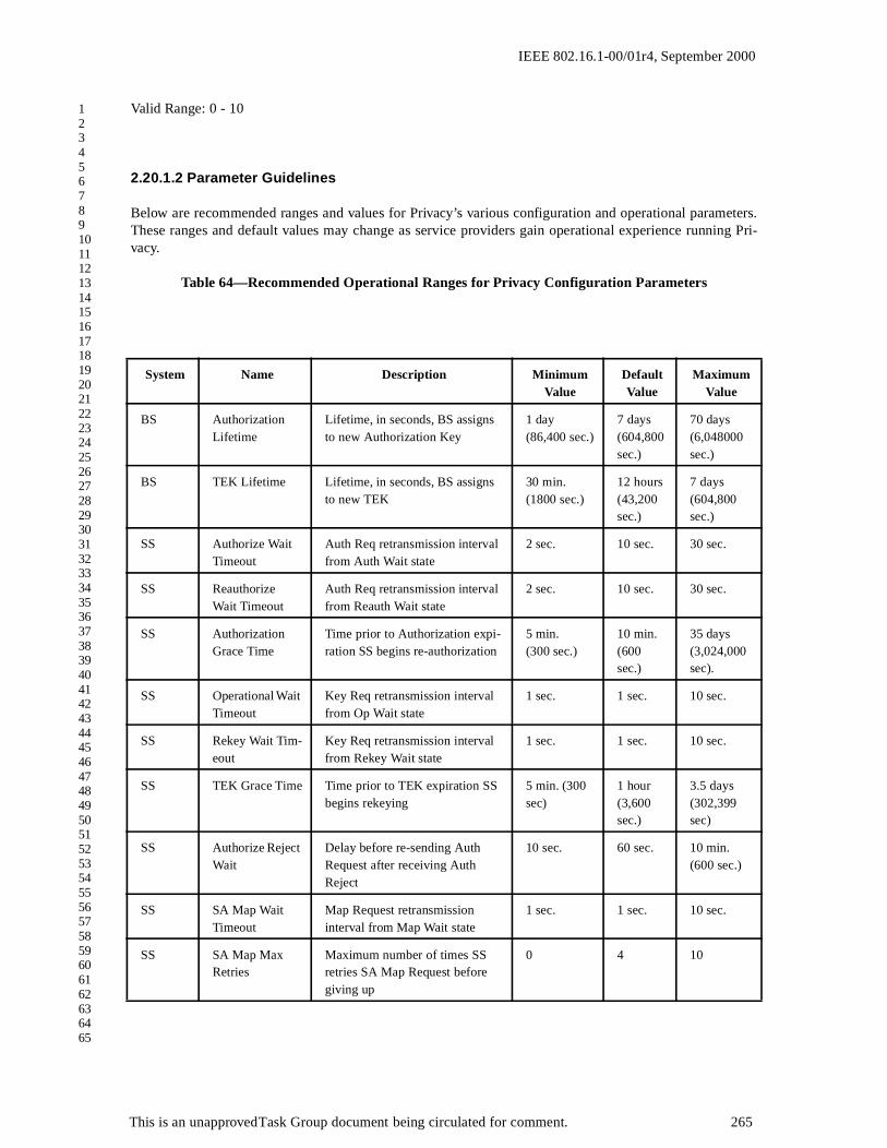
IEEE 802.16.1-00/01r4, September 2000
1234567891011121314151617181920212223242526272829303132333435363738394041424344454647484950515253545556575859606162636465
Valid Range: 0 - 10
2.20.1.2 Parameter Guidelines
Below are recommended ranges and values for Privacy’s various configuration and operational parameters.These ranges and default values may change as service providers gain operational experience running Pri-vacy.
Table 64—Recommended Operational Ranges for Privacy Configuration Parameters
System Name Description Minimum Value
Default Value
Maximum Value
BS Authorization Lifetime
Lifetime, in seconds, BS assigns to new Authorization Key
1 day (86,400 sec.)
7 days (604,800 sec.)
70 days (6,048000 sec.)
BS TEK Lifetime Lifetime, in seconds, BS assigns to new TEK
30 min. (1800 sec.)
12 hours (43,200 sec.)
7 days (604,800 sec.)
SS Authorize Wait Timeout
Auth Req retransmission interval from Auth Wait state
2 sec. 10 sec. 30 sec.
SS Reauthorize Wait Timeout
Auth Req retransmission interval from Reauth Wait state
2 sec. 10 sec. 30 sec.
SS Authorization Grace Time
Time prior to Authorization expi-ration SS begins re-authorization
5 min. (300 sec.)
10 min. (600 sec.)
35 days (3,024,000 sec).
SS Operational Wait Timeout
Key Req retransmission interval from Op Wait state
1 sec. 1 sec. 10 sec.
SS Rekey Wait Tim-eout
Key Req retransmission interval from Rekey Wait state
1 sec. 1 sec. 10 sec.
SS TEK Grace Time Time prior to TEK expiration SS begins rekeying
5 min. (300 sec)
1 hour (3,600 sec.)
3.5 days (302,399 sec)
SS Authorize Reject Wait
Delay before re-sending Auth Request after receiving Auth Reject
10 sec. 60 sec. 10 min. (600 sec.)
SS SA Map Wait Timeout
Map Request retransmission interval from Map Wait state
1 sec. 1 sec. 10 sec.
SS SA Map Max Retries
Maximum number of times SS retries SA Map Request before giving up
0 4 10
This is an unapproved Task Group document being circulated for comment. 265

IEEE 802.16.1-00/01r4, September 2000
1234567891011121314151617181920212223242526272829303132333435363738394041424344454647484950515253545556575859606162636465
The valid range (vs. recommended operational range) for Authorization and TEK lifetimes are:
Authorization Lifetime Valid Range: 1 - 6,048,000 secondsTEK Lifetime Valid Range: 1 - 604,800 seconds
Note that valid ranges defined for each of Privacy’s configuration parameters extend below the recom-mended operational ranges. For the purposes of protocol testing, it is useful to run the privacy protocol withtimer values well below the low end of the recommended operational ranges. The shorter timer values"speed up" prviacy’s clock, causing privacy protocol state machine events to occur far more rapidly than theywould under an "operational" configuration. While privacy implementations need not be designed to operateefficiently at this accelerated privacy pace, the protocol implementation should operate correctly under theseshorter timer values. Table 65 provides a list of shortened parameter values which are likely to be employedin protocol conformance and certification testing.
Table 65—Shortened Privacy Parameter Values for Protocol Testing
The TEK Grace Time shall be less than half the TEK lifetime.
Authorization Lifetime
5 min. (300 sec.)
TEK Lifetime 3 min. (180 sec.)
Authorization Grace Time
1 min. (60 sec.)
TEK Grace time 1 min. (60 sec.)
This is an unapproved Task Group document being circulated for comment. 266

IEEE 802.16.1-00/01r4, September 2000
1234567891011121314151617181920212223242526272829303132333435363738394041424344454647484950515253545556575859606162636465
This is an unapproved Task Group document being circulated for comment. 267

IEEE 802.16.1-00/01r4, September 2000
1234567891011121314151617181920212223242526272829303132333435363738394041424344454647484950515253545556575859606162636465
This is an unapproved Task Group document being circulated for comment. 268

IEEE 802.16.1-00/01r4, September 2000
1234567891011121314151617181920212223242526272829303132333435363738394041424344454647484950515253545556575859606162636465
3 Physical Layer
3.1 Overview
The following physical layer specification was designed to meet the functional requirements that have been definedfor Broadband Wireless Access (BWA) systems. It incorporates many aspects of existing standards in order to lever-age existing technology for reduced equipment cost and demonstrated robustness of implementation, with modifica-tions to ensure reliable operation in the targeted 10-66 GHz frequency band. In addition, this physical layer wasdesigned with a high degree of flexibility in order to allow service providers the ability to optimize system deploy-ments with respect to cell planning, cost considerations, radio capabilities, offered services, and capacity require-ments. Two modes of operation have been defined for the downstream channel, one targeted to support a continuoustransmission stream and one targeted to support a burst transmission stream. Having this separation allows each to beoptimized according to their respective design constraints, while resulting in a standard that supports various systemrequirements and deployment scenarios.
3.1.1 Multiplexing and Multiple Access Technique
The upstream physical layer is based on the use of a combination of time division multiple access (TDMA) anddemand assigned multiple access (DAMA). In particular, the upstream channel is divided into a number of "timeslots". The number of slots assigned for various uses (registration, contention, guard, or user traffic) is controlled bythe MAC layer in the base station and can vary in time for optimal performance. The downstream channel can beeither based upon time division multiplexing (TDM), where the information for each subscriber station is multiplexedonto the same stream of data and is received by all subscriber stations located within the same sector, or in an alterna-tive method (defined for the burst mode of operation) which allows bursts to be transmitted to specific CPEs in a sim-ilar fashion to the TDMA upstream bursts.
3.1.2 Duplexing Technique
Several duplexing techniques are supported with this physical layer. The continuous transmission downstream modethat is defined supports frequency division duplexing (FDD) only, while the burst mode of operation supports FDDwith adaptive modulation or time division duplexing (TDD). The primary difference between the continuous modeand burst mode of operation for supporting FDD is the coding gain and how higher order modulation formats are sup-ported. The continuous downstream mode is based on a concatenated Reed-Solomon, interleaver, and convolutionalcode, and can support different orders of modulation on separate carriers. The burst mode supports the capability tohave different modulation formats transmitted on the same carrier so that the modulation level can be chosen on asubscriber level basis (i.e., adaptive modulation). Note that adaptive modulation is supported with any of the duplex-ing techniques that use the burst mode of operation.
3.1.3 Physical Media Dependent (PMD) Sublayers
Two different downstream physical layers have been defined in this standard. A Mode A downstream physical layerhas been designed for continuous transmission, while a Mode B physical layer has been designed to support a bursttransmission format.
Mode A is based upon a continuous transmission stream supporting a concatenation of Reed Solomon coding, inter-leaving, and convolutional coding for use in an FDD only system. Mode B supports a burst format that allows sys-tems to implement an adaptive modulation scheme for an FDD system as well as supporting TDD configurations.
This approach to standardization allows for service providers the ability to pick the format which best allows them tomeet their system requirements. Standards compliant subscriber stations are required to support at least one of thedownstream modes of operation as defined here.
A single upstream physical layer is also defined here to support a TDMA based burst upstream transmission.
This is an unapproved Task Group document being circulated for comment. 269
IEEE 802.16.1-00/01r4, September 2000
1234567891011121314151617181920212223242526272829303132333435363738394041424344454647484950515253545556575859606162636465
3.1.3.1 Continuous Downstream PMD Sublayer (Mode A) Overview
The Mode A downstream physical layer first encapsulates MAC packets into a convergence layer frame as defined bythe transmission convergence sublayer. Then, the data is randomized and encoded using a (204,188) Reed-Solomoncode over GF(256). Following the outer block encoder, the data goes through a convolutional interleaver with adepth of I=12. Then, the data must either pass through an inner, constraint length 7, convolutional code with a rate of1/2, 2/3, 3/4, 5/6, 7/8, or 1, or pass through a differential encoder (i.e., bypassing the convolutional encoder) asdefined in the following sections. Code bits are then mapped to a QPSK, 16-QAM (optional), or 64-QAM (optional)signal constellation with symbol mapping as described here. Elements that are identified as optional need not beimplemented in order to be standards compliant. However, if these options are supported, they shall be supported inthe manner defined in this standard. Finally, symbols are Nyquist filtered using a square-root raised cosine filter witha roll-off factor of 0.15, 0.25 or 0.35.
3.1.3.2 Burst Downstream PMD Sublayer (Mode B) Overview
The Mode B downstream physical layer has a framing mechanism associated with it that simplifies the support forTDD systems and half-duplex terminals. The frame can either be configured to support a TDM transmission format,which would typically be used in a TDD system or an FDD system supporting adaptive modulation/FEC groups (tobe discussed later). One unique preamble is used to indicate the beginning of a frame, which is followed by the PHY/MAC control data. A PHY control map is used to indicate the beginning of different modulation/FEC groups, whichwill typically be in the order of QPSK followed by 16-QAM and 64-QAM with the FEC scheme chosen to meet eachdesired C/I requirements. In addition, the modulation/FEC group specifications can change with time in order toadjust to the changing channel conditions. Various frame configurations for FDD and TDD are supported, as was dis-cussed in section Figure 2.6.4. All subscriber station data is FEC block encoded allowing for a shortening of the lastcodeword of a burst. The Mode B downstream physical layer also goes through a transmission convergence sublayerthat inserts a pointer byte at the beginning of the payload information bytes to help the receiver identify the beginningof a MAC packet. Data bits coming from the transmission convergence layer are first randomized, encoded using thedefined outer and possibly inner codes, and then mapped, along with the preambles, to a QPSK, 16-QAM, or 64-QAM (optional) signal constellation. The modulated symbols are then Nyquist filtered using a square-root raisedcosine filter with a roll-off factor of 0.15, 0.25 or 0.35.
3.1.3.3 Upstream PMD Sublayer Overview
The upstream physical layer has been designed to support burst modulation for a TDMA based system. Since manyof the specific upstream channel parameters can be programmed by MAC layer messaging coming from the base sta-tion, several parameters can be left unspecified and configured by the base station during the registration process inorder to optimize performance for a particular deployment scenario. In this mode, each burst is designed to carryMAC messages of variable lengths. The transmitter first randomizes the incoming data, and then encodes the datausing an outer code and possibly an inner code to be selected by the MAC messages. The length of the codeword andthe error correction capability of the code are programmable by the MAC messages coming from the base station viaa burst configuration message. Each burst also contains a variable length preamble and a variable length guard spaceat the end of the burst. The preamble and coded bits are mapped to QPSK, 16-QAM (optional), or 64-QAM(optional) constellations. Nyquist pulse shaping using a square-root raised cosine filter is also employed with a roll-off factor of 0.15, 0.25, or 0.35.
3.2 Downstream Physical Layer
This section describes the two different downstream physical layers that have been adopted for use in this standard.A Mode A downstream physical layer has been designed for continuous transmission, while a Mode B physical layerhas been designed to support a burst transmission format. Subscriber stations must support at least one of these phys-ical layers.
This is an unapproved Task Group document being circulated for comment. 270

IEEE 802.16.1-00/01r4, September 2000
1234567891011121314151617181920212223242526272829303132333435363738394041424344454647484950515253545556575859606162636465
3.2.1 Mode A: Continuous Downstream Transmission
This mode of operation has been designed for a continuous transmission stream, using a single modulation/codingcombination on each carrier, in an FDD system (it is not applicable to FSDD or TDD operation). The physical mediadependent sublayer uses a concatenated Reed-Solomon, interleaver, and convolutional code Forward Error Correc-tion coding scheme, and has no explicit frame structure. Where spectrum resources allow, multiple carriers may bedeployed, each using different modulation/coding methods defined here.
3.2.1.1 Mode A Downstream Transmission Convergence (TC) Sublayer
The downstream bitstream is defined as a continuous series of 188-byte packets. These packets consist of a one-bytesynchronization pattern (Byte 1) and a one-byte pointer (Byte 2) followed by 186 bytes of payload (Bytes 3-188).The synchronization byte shall be set to hex 47 and shall be inverted to hex B8 every eight packets in order to resetthe randomization function. The pointer field identifies the byte number in the packet which indicates either thebeginning of the first MAC frame to start in the packet, or indicates the beginning of any stuff bytes that precede thenext MAC frame. For reference, the first byte in the packet is refered to as byte number 1. If no MAC frame beginsin the packet, then the pointer byte is set to 0. When no data is available to transmit, a stuff_byte pattern having avalue (0xFF) must be used within the payload to fill any gaps between the 802.16 MAC frames. This value is chosenas an unused value for the first byte of the 802.16 MAC frame, which is designed to NEVER have this value. Thefollowing figure illustrates the format of the packet leaving the convergence layer.
Figure 116—Format of the Convergence Layer Packet
S 186-byte PayloadP
P = 1 byte pointer fieldS = 1 byte synch. pattern
This is an unapproved Task Group document being circulated for comment. 271

IEEE 802.16.1-00/01r4, September 2000
1234567891011121314151617181920212223242526272829303132333435363738394041424344454647484950515253545556575859606162636465
3.2.1.2 Mode A Physical Media Dependent (PMD) Sublayer
The encoding and decoding functions for the Mode A downstream physical layer are summarized in the following block diagram:
Figure 117— Conceptual Block diagram of the Mode A Downstream Physical Layer
3.2.1.2.1 Baseband interfacing
This unit shall adapt the data structure coming from the MAC layer to the format defined by the transmission conver-gence sublayer defined above.
3.2.1.2.2 Synch. byte inversion and randomization
This unit shall invert the synch. byte according to the transmission convergence sublayer function, and randomizesthe data stream for spectrum shaping purposes. Randomization shall be employed to minimize the possibility oftransmission of an unmodulated carrier and to ensure adequate numbers of bit transitions to support clock recovery.
The stream of uncoded downstream packets, excluding synch. bytes, shall be randomized by modulo-2 addition ofthe data with the output of the pseudo random binary stream (PRBS) generator, as illustrated in the following dia-gram.
Base-band
Interface
Syncbyte
inversion&
Randomization
Reed-SolomonCoder
(204,188)
Convol.Interleaver
Convol.Code
Puncturing/Mapping
BasebandPulse
Shaping
Modulatorand
PhysicalInterface
Data
Base station
To RFChannel
PhysicalInterfaceDemod.
MatchedFilter
&Equalizer
Depunc./Convol.decoder
Convol.de-
interleaver
Reed-SolomonDecoder
Synch1byte
inversion &derandomi
zation
Basebandinterface
Subscriber station
FromRF Channel
Data
This is an unapproved Task Group document being circulated for comment. 272
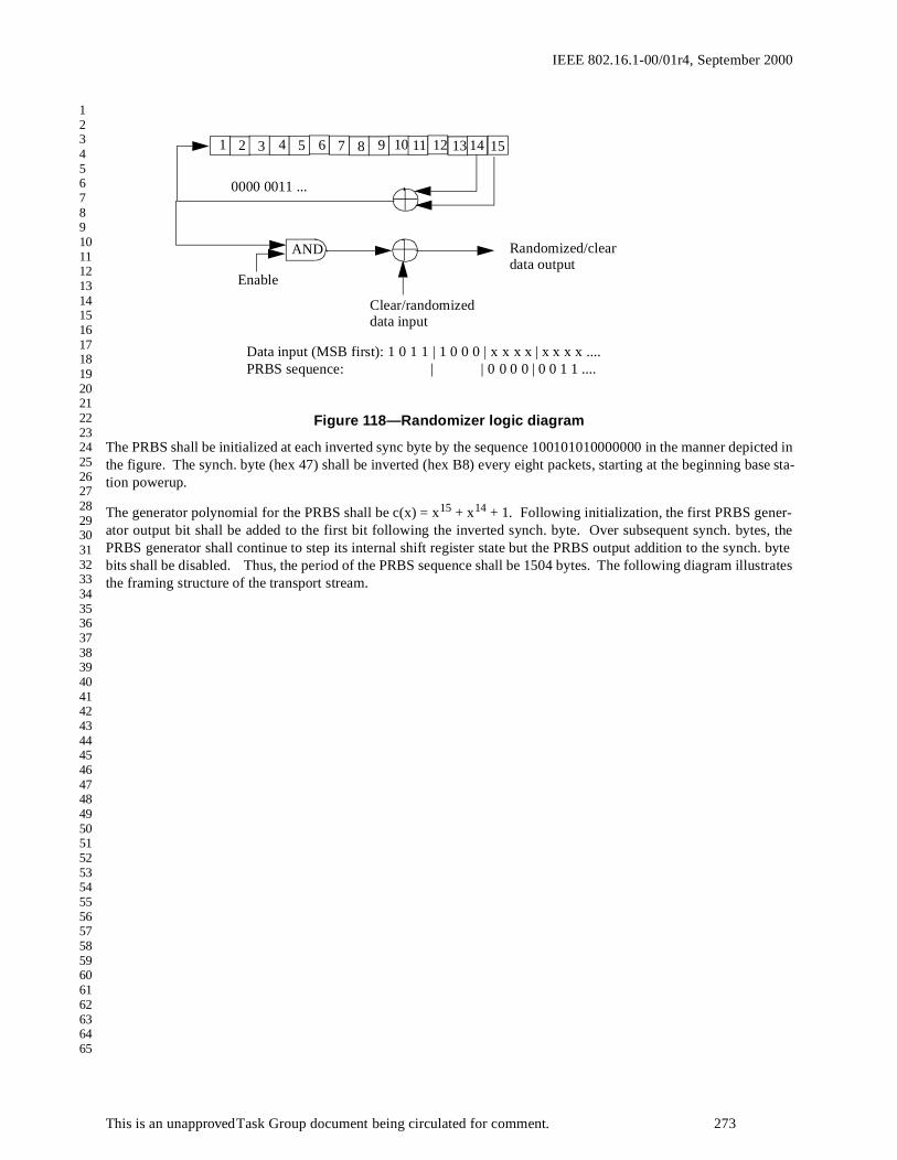
IEEE 802.16.1-00/01r4, September 2000
1234567891011121314151617181920212223242526272829303132333435363738394041424344454647484950515253545556575859606162636465
Figure 118—Randomizer logic diagram
The PRBS shall be initialized at each inverted sync byte by the sequence 100101010000000 in the manner depicted inthe figure. The synch. byte (hex 47) shall be inverted (hex B8) every eight packets, starting at the beginning base sta-tion powerup.
The generator polynomial for the PRBS shall be c(x) = x15 + x14 + 1. Following initialization, the first PRBS gener-ator output bit shall be added to the first bit following the inverted synch. byte. Over subsequent synch. bytes, thePRBS generator shall continue to step its internal shift register state but the PRBS output addition to the synch. bytebits shall be disabled. Thus, the period of the PRBS sequence shall be 1504 bytes. The following diagram illustratesthe framing structure of the transport stream.
1 2 3 4 5 6 7 8 9 10 11 12 13 14 15
AND
Enable
Clear/randomized data input
Randomized/cleardata output
PRBS sequence: | | 0 0 0 0 | 0 0 1 1 .... Data input (MSB first): 1 0 1 1 | 1 0 0 0 | x x x x | x x x x ....
0000 0011 ...
This is an unapproved Task Group document being circulated for comment. 273

IEEE 802.16.1-00/01r4, September 2000
1234567891011121314151617181920212223242526272829303132333435363738394041424344454647484950515253545556575859606162636465
Figure 119— Framing structure based on transmission convergence sublayer.
3.2.1.2.3 Reed Solomon Coding
Following the energy dispersal randomization process, systematic shortened Reed-Solomon encoding shall be per-formed on each randomized transport packet, with T =8. This means that 8 erroneous bytes per transport packet canbe corrected. This process adds 16 parity bytes to the transport packet to give a 204 byte codeword. RS coding shallalso be applied to the packet synch byte, either non-inverted (i.e .47hex) or inverted (i.e. B8hex).
The Reed-Solomon code shall have the following generator polynomials:
Code Generator Polynomial: g(x) = (x+µ0)(x+µ1)(x+µ2)...(x+µ2T-1)where µ= 02hex
Field Generator Polynomial: p(x) = x8 + x4 + x3 + x2 + 1
The shortened Reed-Solomon code shall be implemented by adding 51 bytes, all set to zero, before the informationbytes at the input of a (255,239) encoder; after the coding procedure these bytes are discarded.
Sync.
byte187 bytes
(a) Transmission convergence sublayer packet
Sync1R
187 bytesSync2
R
187 bytesSync8
R
187 bytesSync1
R
187 bytes
(b) Randomized transport packets: Sync bytes and Raondomized Sequence R
Sync.
byte187 bytes RS(204,188)
PRBS period = 1504 bytes
(c) Reed-Solomon RS(204,188,t=8) error protected packet
204 bytes
Sync
bytes203 bytes
Sync
byte203 bytes
(d) Interleaved Frames maintaining sync. byte periodicity
Sync1 = not randomized complemented sync byte
Sync n = not randomized sync byte, n=2...8
This is an unapproved Task Group document being circulated for comment. 274

IEEE 802.16.1-00/01r4, September 2000
1234567891011121314151617181920212223242526272829303132333435363738394041424344454647484950515253545556575859606162636465
3.2.1.2.4 Convolutional interleaving
The convolutional interleaving process shall be based on the Forney approach, with a depth of I=12. The interleavedframe shall be composed of overlapping error protected packets and shall be delimited by synch. bytes (preservingthe periodicity of 204 bytes).
The interleaver is composed of I branches, cyclically connected to the input byte-stream by the input switch. Eachbranch shall be a First In First Out (FIFO) shift register, with depth (M) cells (where M =N/I, N =2 0 4 =error pro-tected frame length, I =12 = maximum interleaving depth, j = branch index). The cells of the FIFO shall contain 1byte, and the input and output switches shall be synchronized, as shown in the diagram below.
For synchronization purposes, the sync bytes and the inverted sync bytes shall be always routed into the branch "0" ofthe interleaver (corresponding to a null delay).
The deinterleaver is similar, in principle, to the interleaver, but the branch indexes are reversed (i.e . j=0 correspondsto the largest delay). The de-interleaver synchronization is achieved by routing the first recognized sync byte into the"0" branch.
Figure 120— Conceptual diagram of the convolutional interleaver and de-interleaver.
3.2.1.2.5 Convolutional Coding with QPSK Modulation
When convolutional encoding is employed, the convolutional code shall be chosen from the following table of coderates, which are obtained by puncturing a rate 1/2 constraint length 7 code having the following generator vectors G,and puncturing patterns P (0 denotes punctured (deleted) bit).
M
M M
M M M
M M M M
M
M M
M M M
M M M M0
1
2
3
I-1
0
1
2
3
I-1
0
I-4
I-3
I-2
I-1
0
I-4
I-3
I-2
I-1
1 byte per
position
Channel
Convolutional Interleaver Convolutional De-interleaver
M M-stage FIFO shift register
sync word routesync word route
This is an unapproved Task Group document being circulated for comment. 275

IEEE 802.16.1-00/01r4, September 2000
1234567891011121314151617181920212223242526272829303132333435363738394041424344454647484950515253545556575859606162636465
Table 66—Convolutional Code Puncture Patterns
The QPSK symbols will use gray-coded direct mapping of (I,Q) from bit pairs out of the convolutional encoder asfollows:
Figure 121— QPSK symbol mapping
3.2.1.2.6 Convolutional Coding with 16-QAM Modulation (optional)
16-QAM shall be supported using a rate 3/4 or 7/8 punctured convolutional code with the inner coding and constella-tion mapping as described in [xxx].
3.2.1.2.7 Differential encoding with QPSK or 16-QAM Modulation (16-QAM is optional)
In this mode, the inner convolutional code is disabled, and the mapping of bits to symbols shall use the following dif-ferential encoder and mapper as defined in ITU-T J.83 Annex A. The two most significant bits (MSBs) of each sym-
bol shall be differentially coded in order to obtain a π/2 rotation-invariant QAM constellation. The differentialencoding of the two MSBs shall be given by the following Boolean expression:
1/2 2/3 3/4 5/6 7/8
G1 G2 P Df P Df P Df P Df P Df
171 oct
133 oct
X=1 Y=1 I=X1 Q=Y1
10 X=10 Y=11 I=X1Y2Y3 Q=Y1X3Y4
6 X=101 Y=110 I=X1Y2 Q=Y1X3
5 X=10101 Y=11010 I=X1Y2Y4 Q=Y1X3X5
4 X=1000101 Y=1111010 I=X1Y2Y4Y6 Q=Y1Y3X5X7
3
0010
0111
Ik Ak Bk⊕( ) Ak Ik-1⊕( )⋅ Ak Bk⊕( ) Ak Qk-1⊕( )⋅+=
Qk Ak Bk⊕( ) Bk Qk-1⊕( )⋅ Ak Bk⊕( ) Bk Ik-1⊕( )⋅+=
This is an unapproved Task Group document being circulated for comment. 276

IEEE 802.16.1-00/01r4, September 2000
1234567891011121314151617181920212223242526272829303132333435363738394041424344454647484950515253545556575859606162636465
ical OR func-
Note: For the above Boolean expressio n "" denotes the EXOR function, "" denotes the logtion, " " denotes the logical AND function and the overstrike denotes inversion.
The following figure gives an example of implementation of byte-to-symbol conversion.
Figure 122— Example implementation of the byte to m-tuple conversion and the differential encoding of the two MSBs.
For QPSK, the output of the differential encoder shall map directly to the QPSK signal constellation based on theQuadrant to MSB mapping shown in the following table. The mapping of bits to symbols for 16-QAM, when imple-mented as an option, is given by the following figure.
Table 67— Conversion of constellation of quadrant 1 to other quadrants of the constellation diagrams given in the following diagrams.
Quadrant MSBs LSBs rotation
1 00 0
2 10 +π/2
3 11 + π
4 01 + 3π/2
a b⊕ a b+
a b⋅
fro m
con v o lu tio n a l
in te r leav er
B y te
to
m - tu p le
co n v ersio n I k
Q k
q -1 0
B k= b
q
Ak
= bq + 1
I an d Q
m ap p in gd if fe ren tia l
en co d in g
I
Q
8
q = 0 fo r Q P SK , q = 2 fo r 1 6 -Q A M
This is an unapproved Task Group document being circulated for comment. 277

IEEE 802.16.1-00/01r4, September 2000
1234567891011121314151617181920212223242526272829303132333435363738394041424344454647484950515253545556575859606162636465
Figure 123—16-QAM Constellation Diagram
3.2.1.2.8 Differential encoding with 64-QAM Modulation (optional)
64-QAM modulation shall be optionally supported in this specification in order to allow for the future support forhigher capacity links. This option uses the same differential encoding structure described above, with q=4 in the dif-ferential encoder, and the following mapping of bits to symbols.
I
Q1 0
0 0 0 1
1 1
I Qk k
= 00
1 1
1 0 00
01
I Qk k
= 10
0 1
1 1 10
00
I Qk k
= 11
0 0
0 1 1 1
1 0
I Qk k
= 01
I
Q
I Qk k
= 00I Qk k
= 10
I Qk k
= 11 I Qk k
= 01
1000 1001 1101 1100
1010 1011 1111 1110
0010 0011 0111 0110
0100010100010000
0100
0101
0000
1100 1110 0110
1101 1111 0111
1001 1011 0011
001010101000
0001
0000 0010 1010
0001 0011 1011
0101 0111
1110
1111
01100100
1000
1001
1101
1100
0100 0101 0001
0110 0111 0011
1110 1111
1001
1011
11011100
0000
0010
1010
1000
This is an unapproved Task Group document being circulated for comment. 278

IEEE 802.16.1-00/01r4, September 2000
1234567891011121314151617181920212223242526272829303132333435363738394041424344454647484950515253545556575859606162636465
Figure 124—64-QAM Constellation Diagram
3.2.1.2.9 Baseband Pulse Shaping
Prior to modulation, the I and Q signals shall be filtered by square-root raised cosine filters. The excess bandwidthfactor α shall be either 0.15, 0.25 or 0.35. The ideal square-root raised cosine filter is defined by the following trans-fer function H:
where is the Nyquist frequency.
3.2.1.2.10 Summary of Mode A Downstream Physical Layer Parameters
3.2.2 Mode B: Burst Downstream Transmission
This mode of operation has been designed to support burst transmission in the downstream channel. In particular,this mode is applicable for systems using adaptive modulation in an FDD system or for systems using TDD, both ofwhich require a burst capability in the downstream channel. Operating with a burst capability puts some constraintson several aspects of the physical layer, primarily with respect to phase recovery and allowable codeword lengths,which are taken into account in this mode of operation. In order to simplify phase recovery and channel tracking, afixed frame time is used. At the beginning of every frame, a preamble is transmitted in order to allow for phaserecover and equalization training. A description of the framing mechanism and the structure of the frame is furtherdescribed in Section Section 2.6.4.
Randomization 1 + X14 + X15
Initialization: 100101010000000
Reed-Solomon Coding (204,188) with T=8 byte errors corrected
Interleaving Convolutional with depth I=12.
Convolutional coding Selectable: rate 1/2, 2/3, 3/4, 5/6, 7/8,or 1 (disabled)
Modulation QPSK, 16-QAM (optional), or 64-QAM (optional)
Differential encoding enabled/disabled (enabled only when convolutional cod-ing is not employed)
Spectral shaping α=0.15, 0.25 or 0.35
Spectral inversion inverted or non-inverted
H f( ) 1=( ) for f fN 1 α–( )<( )
H f( ) 12--- 1
2--- π
2fN
--------fN f–
α-------------sin+
12---
=
for fN 1 α–( )( ) f fN 1 α+( )( )≤ ≤( )
H f( ) 0=( ) for f fN 1 α+( )>( )
fN1
2TS---------
RS
2------= =
This is an unapproved Task Group document being circulated for comment. 279

IEEE 802.16.1-00/01r4, September 2000
1234567891011121314151617181920212223242526272829303132333435363738394041424344454647484950515253545556575859606162636465
3.2.2.1 Mode B Downstream Transmission Convergence (TC) Sublayer
First, the downstream payload is segmented into blocks of data designed to fit into the proper codeword size after theconvergence layer bytes are added. Note that the payload length may vary, depending on whether shortening of code-words is allowed or not for this burst type. A pointer byte is then added to each payload segment, as shown in the fol-lowing figure:
Figure 125— Format of the Convergence Layer Packet
The pointer field identifies the byte number in the packet which indicates either the beginning of the first MAC frameto start in the packet, or indicates the beginning of any stuff bytes that precede the next MAC frame. For reference,the first byte in the packet is refered to as byte number 1. If no MAC frame begins in the packet, then the pointer byteis set to 0. When no data is available to transmit, a stuff_byte pattern having a value (0xFF) must be used within thepayload to fill any gaps between the 802.16 MAC frames. This value is chosen as an unused value for the first byteof the 802.16 MAC frame, which is designed to NEVER have this value.
3.2.2.2 Mode B Physical Media Dependent (PMD) Sublayer
The downstream physical layer coding and modulation for this mode is summarized in the block diagram shownbelow.
Variable length PayloadP
P = 1 byte pointer field
This is an unapproved Task Group document being circulated for comment. 280

IEEE 802.16.1-00/01r4, September 2000
1234567891011121314151617181920212223242526272829303132333435363738394041424344454647484950515253545556575859606162636465
Figure 126—Conceptual Block diagram of the Mode B Downstream Physical Layer
3.2.2.2.1 Modulation/FEC Group Definitions
The downstream channel supports flexible modulation types and FEC coding on the user data portion of the frame.Up to 16 modulation/FEC groups can be defined, each having the following parameters that are communicated to thesubscriber stations via MAC messages during the control portion of the downstream frame, which immediately fol-lows the frame start preamble (see framing discussion from Section Section 2.6.4). Note that the control portion ofthe frame has a fixed modulation (QPSK) and FEC scheme in order to allow the subscriber stations to detect theMAC messages required to complete the registration process. After registration and authorization by the base station,the subscriber station shall be assigned a particular modulation type and FEC type to be used for its user data. Thedownstream channel and burst profiles are communicated to the CPEs via the MAC messages described in Section2.5.2.2.
3.2.2.2.2 Downstream Physical Layer Terminal Capability Set Parameters
Since there exists some optional modulation and FEC schemes that can be implemented at the subscriber station,there must exist some method for identifying the capability to the base station (i.e., including the highest order modu-latoin supported, the optional FEC coding schemes supported, interleaving type supported, and the minimum short-ened last codeword length supported). This information shall be communicated to the base station during thesubscriber registration period using the Registration Request and Response MAC messages described in Sections2.5.7 and 2.5.8.
3.2.2.2.3 Randomization
Randomization shall be employed to minimize the possibility of transmission of an unmodulated carrier and to ensureadequate numbers of bit transitions to support clock recovery. The stream of downstream packets shall be random-
RandomizationFEC
EncoderPreamblePrepend
BasebandPulse
Shaping
Modulatorand
PhysicalInterface
Data
Subscriber Station
To RFChannel
FromRF Channel Data
De-randomization
SymbolDe-mapper
MatchedFilter
FECDecoder
PhysicalInterfaceand BurstDemod.
Base station
SymbolMapper
This is an unapproved Task Group document being circulated for comment. 281

IEEE 802.16.1-00/01r4, September 2000
1234567891011121314151617181920212223242526272829303132333435363738394041424344454647484950515253545556575859606162636465
ized by modulo-2 addition of the data with the output of the pseudo random binary stream (PRBS) generator, as illus-trated in the following diagram.
Figure 127—Randomizer logic diagram.
At the beginning of each burst, the PRBS register is cleared and the seed value of 100101010000000 is loaded. Notethat a burst corresponds either to a TDM burst starting with a frame start preamble (Preamble 1 in the next section) ora TDMA burst starting with a shortened preamble (Preamble 2 in the next section). The seed value must be used tocalculate the randomization bit, which is combined in an XOR with the first bit of data of each burst.
3.2.2.2.4 Forward Error Correction (FEC)
The forward error correction schemes for the Mode B downstream channel are selectable from the following types:
Note that the first two code types MUST be implemented by all subscriber stations, while code types 3 and 4 areoptional.
Following is a summary of the four coding options:
(1) Reed-Solomon only: This case is useful either for a large data block or when high coding rate is required. Theprotection could vary between t=1 to t=16.
(2) Reed-Solomon + Block convolutional code (soft decodable): This case is useful for low to moderate coding ratesproviding good C/N enhancements. The coding rate is 2/3.
(3) Reed-Solomon + Parity check: This optional code his useful for moderate to high coding rates with small tomedium size blocks (i.e., K=16, 53 or 128). The code itself is a simple bit wise parity check operating on byte (8 bit)level.
Table 68—FEC Code Types for Burst Downstream (Mode B)
Code Type Outer Code Inner Code
1 Reed Solomon over GF(256) None
2 Reed Solomon over GF(256) (24,16) Block convolutional code
3(Optional) Reed Solomon over GF(256) (9,8) Parity check code
4 (Optional) Block Turbo Code ---
1 2 3 4 5 6 7 8 9 10 11 12 13 14 15
AND
Enable
Clear/randomized data input
Randomized/cleardata output
0000 0011 ...
This is an unapproved Task Group document being circulated for comment. 282

IEEE 802.16.1-00/01r4, September 2000
1234567891011121314151617181920212223242526272829303132333435363738394041424344454647484950515253545556575859606162636465
(4) Block Turbo Code: This optional code is used to significantly lower the required C/I level needed for reliablecommunication, and can be used to either extend the range of a base station or increase the code rate for greaterthroughput.
3.2.2.2.5 Reed Solomon Encoding (for code types 1-3)
The outer block code for code types 1-3 shall be a shortened, systematic Reed-Solomon code generated fromGF(256) with information block lengths (K) variable from 6-255 bytes and error correction capability able to correctup to 16 byte errors. The specified code generator polynomials are given by
Code Generator Polynomial: g(x) = (x+µ0)(x+µ1)(x+µ2) ... (x+µ2T-1), where µ= 02hex
Field Generator Polynomial: p(x) = x8 + x4 + x3 + x2 + 1
The specified code has a block length of 255 bytes, and shall be configured as a RS(255,255-R) code with informa-tion bytes preceded by (255-N) zero symbols, where N is the codeword length and R the number of redundancy bytesR=0 to 32. In the case of code type 3, R should be chosen odd if K is odd and should be chosen even if K is even inorder to ensure an even number of bytes in the codeword.
When the number of bytes entering the FEC process M is less than K bytes, the following operation is performed:
(1) (K-M) zero bytes are added to the M byte block as a prefix
(2) RS Encoding is performed
(3) If inner code is either of type 1 or 2 or if the code type 3 with (M+R) even, then
All of the (K-M) zero RS symbols not associated with the original data are discarded
(4) If inner code is code type 3 with (M+R) odd, then
The first (K-M-1) zero RS symbols not associated with the original data are discarded
(5) Inner coding is performed on remaining symbols
(6) The resulting byte block is converted to bit block
When the number of bytes entering the FEC process M is greater than K bytes, the following operation is performed:
(1) Encode K bytes
(2) Subtract K from M, meaning Let M=M-K
(3) If M<K then go to (4), otherwise go to (1)
(4) Shortened FEC is applied to the remaining bytes as described above.
It is expected that the receiver, having knowledge of the expected data length, would properly zero pad the receivedblock and decode it afterwards.
3.2.2.2.6 Code 2: Rate 2/3 Block Convolutional Code
The inner code in this concatenated coding scheme consists of short block codes derived from a 4-state, nonsystem-atic, punctured convolutional code (7,5)8. The trellis shall use the tail-biting method, where the last 2 bits of the
block are used to initialize the encoder memory, in order to avoid the overhead required for trellis termination.
For this concatenated coding scheme, the inner code message block is selected to be 16 bits. The puncturing pattern isdescribed in the following table for the (24,16) case.
This is an unapproved Task Group document being circulated for comment. 283

IEEE 802.16.1-00/01r4, September 2000
1234567891011121314151617181920212223242526272829303132333435363738394041424344454647484950515253545556575859606162636465
Table 69—The Parameters of the Inner Codes for the Block Convolutional Code
3.2.2.2.7 Code 3: Parity Check (Optional)
For the code type 3, a parity check bit is added to each RS symbol individually and inserted as the MSB of the result-ing 9-bit word. The parity is an exclusive-or operation on all 8 bits within the symbol. The result is a 9(K+R) block ofbits, LSB first.
3.2.2.2.8 Code 4: Block Turbo Code (Optional)
The Block Turbo Code (BTC) is a Turbo decoded Product Code (TPC). The idea of this coding scheme is to useextended Hamming block codes in a two dimensional matrix. The two-dimensional code block is depicted in Figure128. The kx information bits in the rows are encoded into nx bits, by using an extended Hamming binary block (nx,kx)
code. Likewise, ky information bits in the columns are encoded into ny bits, by using the same or possibly different
extended Hamming binary block (ny,ky) code. The resultant code block is comprised of multiple rows and columns
of the constituent extended Hamming block codes.
Because extended Hamming codes are linear codes, it does not matter whether the rows or columns are encoded first.For this standard, the rows shall be encoded first. After encoding the rows, the columns are encoded using anotherblock code (ny,ky), where the check bits of the first code are also encoded. The overall block size of such a product
code is n = nx x ny, the total number of information bits kx x ky, the code rate is R = R x x Ry, where Ri = ki/ni and i=x
or y.
Figure 128—Two-dimensional product code matrix.
Inner Code Rate Puncture pattern
G1 = 7, G2 = 5
2/3 11, 10
checksonchecks
checks
checksk2
n2
n1
k1
informationbits
This is an unapproved Task Group document being circulated for comment. 284

IEEE 802.16.1-00/01r4, September 2000
1234567891011121314151617181920212223242526272829303132333435363738394041424344454647484950515253545556575859606162636465
Table 70 provides the generator polynomials of the constituent Hamming codes used in this specification.
The composite extended Hamming code specified requires addition of an overall even parity check bit at the end ofeach codeword.
The encoder for a Block Turbo Code (BTCs) is composed of linear feedback shift registers (LFSRs), storage ele-ments, and control logic. An example row (or column) encoder is shown here for clarification. The order of trans-mission is important since the decoder must match for proper decoding. This specification mandates that theresultant code block be transmitted row by row, left to right, top to bottom, for the case when no interleaving is used(Interleaver Type 1 described below).
Figure 129 shows an example LFSR based on a x4 + x + 1 Hamming code polynomial to encode a (15,11) Hammingcode. Also shown is an even parity computation register that results in an extended Hamming code. Note that encod-ers for the required (64,57) and (32,26) codes follow the same design concept. This figure is shown for clarificationof the BTC encoder design and does not depict an actual design implementation.
Figure 129—Example Encoder for a (16,11) Extended Hamming Code
The example circuit begins with all toggle switches in position A. Data to be encoded is fed as input one bit per clock(LSB first) to both the Hamming error correction code (ECC) computation logic and the overall even parity computa-tion logic. Extended Hamming codes are systematic codes, so this data is also fed through as output on the encodedbit output. After all k bits are input, the toggle switches are moved to position B. At this point, data from the Ham-
Table 70—Hamming Code Generator Polynomials
n k Generator Polynomial
31 26
63 57
x5 x2 1+ +
x6 x 1+ +
Data Bits A
B,C
A
B,C
C
A,B
C
Overall Parity Computation
Hamming ECC Computation
1 x x4
Encoded Bits
A,B
This is an unapproved Task Group document being circulated for comment. 285

IEEE 802.16.1-00/01r4, September 2000
1234567891011121314151617181920212223242526272829303132333435363738394041424344454647484950515253545556575859606162636465
ming ECC logic is shifted out on the encoded bits bus. Finally, the overall parity bit is shifted out when the outputselect switch is moved to position C.
In order to encode the product code, each data bit is fed as input both into a row LFSR and a column LFSR. Note thatonly one row LFSR is necessary for the entire block, since data is written as input in row order. However, each col-umn of the array must be encoded with a separate LFSR. Each column LFSR is clocked for only one bit of the row,so a more efficient method of column encoding is to store the column LFSR states in a kx x (ny-ky) storage memory.
A single LFSR can then be used for all columns of the array. With each bit input, the appropriate column LFSR stateis read from the memory, clocked, and written back to the memory.
The encoding process will be demonstrated with an example. Assume a two-dimensional (8,4)x(8,4) extended Ham-ming Product code is to be encoded. This block has 16 data bits, and 64 total encoded bits. Table 71 shows the orig-inal 16 data bits denoted by Dyx, where y corresponds to a column and x corresponds to a row.
The first four bits of the array are fed into the row encoder input in the order D 11, D21, D31, D41. Each bit is also fed
as input into a unique column encoder. Again, a single column encoder may be used, with the state of each columnstored in a memory. After the fourth bit is fed into the input, the first row encoder ECC bits are shifted out.
This process continues for all four rows of data. At this point, 32 bits have been taken as output from the encoder, andthe four column encoders are ready to shift out the column ECC bits. This data is shifted out at the end of the row.This continues from the remaining 3 rows of the array. Table 72 shows the final encoded block with the 48 generatedECC bits denoted by Eyx.
Table 71—Original Data for Encoding
D11 D21 D31 D41
D12 D22 D32 D42
D13 D23 D33 D43
D14 D24 D34 D44
Table 72—Encoded Block
D11 D21 D31 D41 E51 E61 E71 E81
D12 D22 D32 D42 E52 E62 E72 E82
D13 D23 D33 D43 E53 E63 E73 E83
D14 D24 D34 D44 E54 E64 E74 E84
E15 E25 E35 E45 E55 E65 E75 E85
E16 E26 E36 E46 E56 E66 E76 E86
E17 E27 E37 E47 E57 E67 E77 E87
E18 E28 E38 E48 E58 E68 E78 E88
This is an unapproved Task Group document being circulated for comment. 286

IEEE 802.16.1-00/01r4, September 2000
1234567891011121314151617181920212223242526272829303132333435363738394041424344454647484950515253545556575859606162636465
Transmission of the block over the channel occurs in a linear manner; all bits of the first row are transmitted left toright, followed by the second row, etc. This allows for the construction of a near zero-latency encoder, since the databits can be sent immediately over the channel, with the ECC bits inserted as necessary. For the (8,4)x(8,4) example,the output order for the 64 encoded bits is D11, D21, D31, D41, E51, E61, E71, E81, D12, D22, … E88.
For easier readability, the following notation is used:
1. The codes defined for the rows (x-axis) are binary (nx,kx) block codes.
2. The codes defined for the columns (y-axis) are binary (ny,ky) block codes.
3. Data bits are noted Dyx and parity bits are noted Eyx.
Shortened BTC
To match packet sizes, removing symbols from the array shortens a product code. Either rows or columns can beremoved until the appropriate size is reached. Note that parity bits are removed as part of the shortening process,helping to keep the code rate high. Shortening is accomplished by removing entire rows and/or columns from thearray. This is equivalent to shortening the constituent codes that make up the product code. This method enables acoarse granularity on shortening, and at the same time maintains the highest code rate possible by removing both dataand parity symbols.
Shortened Two -Dimensional BTC example
For example, the 128 byte BTC code in this specification is composed of (64,57) constituent codes in the two dimen-sional array, which has been shortened by 25 rows and columns to form a (39,32) x (39,32) array. This code blockhas 32 x 32 = 1024 data bits, which results in the desired 128 byte information block. Figure 138 shows the structureof the resultant block.
Figure 130—Structure of Shortened 2 D Block
Modifications to the encoder to support shortening are minimal. Since shortened bits are always zero, and zeros inputto the encoder LFSR result in a zero state, the shortened bits can simply be ignored for the purposes of encoding. The
Data Bits
ECC Bits
Unshortened Block
57 bits 7 bits
57 bits
7 bits
x
y
Shortened Block
This is an unapproved Task Group document being circulated for comment. 287

IEEE 802.16.1-00/01r4, September 2000
1234567891011121314151617181920212223242526272829303132333435363738394041424344454647484950515253545556575859606162636465
encoder simply needs to know how many bits per row to input to the row LFSR before shifting out the result. Simi-larly, it must know the number of columns to input to the column encoders.
Transmission of the resultant code block must start with the first data bit in the first row, proceed left to right and thenrow by row from top to bottom.
Table 73—Required Block Codes for the BTC Option for the Downlink Channel
Interleaving
When using the Block Turbo Coding, two modes of bit interleaving shall be supported. The interleaver mechanismshall be implemented by writing information bits into the encoder memory and reading out the encoded bits as fol-lows:
1. Interleaver type 1: No interleaver.
In this mode the encoded bits are read from the encoder row by row, in the order that they were written.
2. Interleaver type 2: Block interleaver.
In this mode the encoded bits are read from the encoder, only after all first k2 rows were written into the encoder
memory. The bits are read column-by-column, proceeding from the top position in the first column.
3. Interleaver type 3: Reserved.
It is expected that other interleaving methods may yield better performance in some cases. So, this Interleaver type 3has been reserved for future definition.
Block mapping to the signal constellation
The first encoded bit out shall be the LSB, which is the first bit written into the encoder.
Method for determining codes for payload size different than the listed examples
The following text describes a method for performing additional codeword shortening when the input block of datadoes not match exactly the codeword information size.
1 Take the required payload as specified in bytes and convert it to bits (i.e., multiple by 8).
2 Take the square root of the resultant number.
3 Round the result up to the next highest integer.
4 Select the smallest base constituent code from the available list that has a k value equal to or greater than thevalue determined in step 3.
Table 3-1:
Code (39,32)x(39,32) (63,56)x(63,56)
Aggregate Code Rate
0.673 0.790
Uplink/Downlink/Both
Downlink Downlink
Block size (pay-load bits)
1024 (128 bytes) 3136 (392 bytes)
This is an unapproved Task Group document being circulated for comment. 288

IEEE 802.16.1-00/01r4, September 2000
This is an unapproved Task Group document being circulated for comment. 289
1234567891011121314151617181920212223242526272829303132333435363738394041424344454647484950515253545556575859606162636465
5 Subtract the value determined in step 3 from the k value selected in step 4. This value represents the numberof rows and columns that need to be shortened from the base constituent code selected in step 4.
This method will generally result in a code block whose payload is slightly larger than required in step 1. In order toaddress the residual bits, the column dimension (ny,ky) should be shortened as needed as well as stuffing zero bits as
needed into the last bits of the last row of the resulting code matrix. The zero bits in the last row should be discardedat the receiver.
Example: If a 20 byte payload code is desired, a (32,26) x (32,26) code is shortened by 13 rows and by 13 columns,which results in a (19,13) x (19,13) code. There are 9 bits left over which are stuffed with zeros. Data input to thedefined encoder is 160 data bits followed by 9 zero bits. The code block is transmitted starting with the bit in row 1column 1 (the LSB), then left to right, and then row by row.
3.2.2.2.9 Coding for the PHY/MAC control message portion of the frame
The PHY/MAC control portion of the downstream frame shall be encoded with a fixed set of parameters in order toensure that all subscriber stations can read the information. The modulation shall be QPSK, and the PHY/MAC con-trol portion of the frame shall be encoded with an outer (40,20) Reed-Solomon code and an inner (24,16) convolu-tional code. There must be a minimum of 2 codewords per control portion of the frame when a downstreamallocation map is present.
3.2.2.2.10 Burst Preambles
Tables 74 through 76 define the preambles for the different downstream burst types. These preamble are based uponCAZAC sequences. The frame start preamble is always at the first part of a downstream frame and consists of a 32symbol preamble (Burst Preamble 1), which is generated by repeating twice a CAZAC sequence of length 16 sym-bols. In the case of the TDMA mode on a downstream, user bursts are transmitted with a shortened preamble of 16symbols (Burst Preamble 2), which is generated with a single length 16 CAZAC sequence. Note that these sequenceshave been shifted by +45 degrees in order to result in the same QPSK data symbol constellations.
Table 74— Burst Preamble Types
Table 75 defines the bit sequence for burst preamble 1.
Table 75— Burst Preamble 1
Burst type Preamble Type
Modulation Type
Downstream burst, Frame begin 1 QPSK
Downstream TDMA burst 2 QPSK
Symbol I Q B(1) B(2)
1 1 1 0 0
2 -1 1 1 0
3 -1 -1 1 1
4 1 -1 0 1

IEEE 802.16.1-00/01r4, September 2000
This is an unapproved Task Group document being circulated for comment. 290
1234567891011121314151617181920212223242526272829303132333435363738394041424344454647484950515253545556575859606162636465
5 1 1 0 0
6 -1 -1 1 1
7 1 1 0 0
8 -1 -1 1 1
9 1 1 0 0
10 1 -1 0 1
11 -1 -1 1 1
12 -1 1 1 0
13 1 1 0 0
14 1 1 0 0
15 1 1 0 0
16 1 1 0 0
17 1 1 0 0
18 -1 1 1 0
19 -1 -1 1 1
20 1 -1 0 1
21 1 1 0 0
22 -1 -1 1 1
23 1 1 0 0
24 -1 -1 1 1
25 1 1 0 0
26 1 -1 0 1
27 -1 -1 1 1
28 -1 1 1 0
29 1 1 0 0
30 1 1 0 0
31 1 1 0 0
32 1 1 0 0

IEEE 802.16.1-00/01r4, September 2000
This is an unapproved Task Group document being circulated for comment. 291
1234567891011121314151617181920212223242526272829303132333435363738394041424344454647484950515253545556575859606162636465
Table 76 defines the bit sequence for burst preamble 2.
Table 76—Burst Preamble 2
3.2.2.2.11 Modulation
To maximize utilization of the air-link, the physical layer uses a multi-level modulation scheme. The modulation con-stellation can be selected based on the quality of the RF channel per subscriber. If link conditions permit, then a morecomplex modulation scheme can be utilized hence maximizing air-link throughput while still allowing reliable datatransfer. If the air-link degrades over time, possibly due to environmental factors, the system can revert to the lesscomplex constellations to allow more reliable data transfer.
The modulation used by the BS in the downstream shall be QPSK, 16-QAM, (both mandatory) and 64-QAM.
The sequence of modulation bits shall be mapped onto a sequence of modulation symbols S(k), where k is the corre-sponding symbol number. The number of bits per symbol is a result from the modulation type, for QPSK n=2, for 16-QAM n=4, for 64-QAM n=6. B(m) denotes the modulation bit of a sequence to be transmitted, where m is the bitnumber (m=1..n). In particular, B(1) corresponds to the first bit entering the modulator, B(2) corresponds to the sec-ond bit entering the modulation, and so on.
The complex modulation symbol S(k) shall take the value I +jQ. The following subsections apply to the base-bandpart of the transmitter.
Symbol I Q B(1) B(2)
1 1 -1 0 1
2 -1 -1 1 1
3 1 1 0 0
4 1 1 0 0
5 1 1 0 0
6 -1 1 1 0
7 1 1 0 0
8 -1 -1 1 1
9 -1 1 1 0
10 1 1 0 0
11 1 1 0 0
12 1 1 0 0
13 -1 -1 1 1
14 1 -1 0 1
15 1 1 0 0
16 -1 -1 1 1
Figure 131 and Table 77 describe the bit mapping for QPSK modulation.
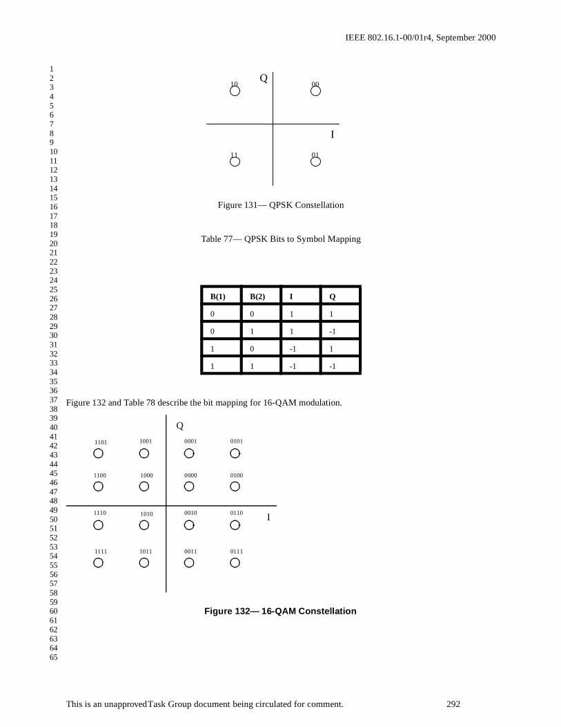
IEEE 802.16.1-00/01r4, September 2000
1234567891011121314151617181920212223242526272829303132333435363738394041424344454647484950515253545556575859606162636465
Figure 131— QPSK Constellation
Table 77— QPSK Bits to Symbol Mapping
Figure 132 and Table 78 describe the bit mapping for 16-QAM modulation.
Figure 132— 16-QAM Constellation
B(1) B(2) I Q
0 0 1 1
0 1 1 -1
1 0 -1 1
1 1 -1 -1
1101 1001 0001 0101
1100 1000 0000 0100
1110 1010 0010 0110
1111 1011 0011 0111
I
Q
00 10
11 01
I
Q
This is an unapproved Task Group document being circulated for comment. 292

IEEE 802.16.1-00/01r4, September 2000
1234567891011121314151617181920212223242526272829303132333435363738394041424344454647484950515253545556575859606162636465
Table 78— 16-QAM Bits to Symbol Mapping
Figure 133 and Table 79 describe the bit mapping for 64-QAM modulation.
B(1) B(2) B(3) B(4) I Q
0 1 0 1 3 3
0 1 0 0 3 1
0 1 1 0 3 -1
0 1 1 1 3 -3
0 0 0 1 1 3
0 0 0 0 1 1
0 0 1 0 1 -1
0 0 1 1 1 -3
1 0 0 1 -1 3
1 0 0 0 -1 1
1 0 1 0 -1 -1
1 0 1 1 -1 -3
1 1 0 1 -3 3
1 1 0 0 -3 1
1 1 1 0 -3 -1
1 1 1 1 -3 -3
This is an unapproved Task Group document being circulated for comment. 293

IEEE 802.16.1-00/01r4, September 2000
1234567891011121314151617181920212223242526272829303132333435363738394041424344454647484950515253545556575859606162636465
Figure 133— 64-QAM ConstellationTable 79— 64-QAM Bits to Symbol Mapping
B(1) B(2) B(3) B(4) B(5) B(6) I Q
0 1 1 0 1 1 7 7
0 1 1 0 1 0 7 5
0 1 1 0 0 0 7 3
0 1 1 0 0 1 7 1
0 1 1 1 0 1 7 -1
0 1 1 1 0 0 7 -3
0 1 1 1 1 0 7 -5
0 1 1 1 1 1 7 -7
0 1 0 0 1 1 5 7
0 1 0 0 1 0 5 5
0 1 0 0 0 0 5 3
0 1 0 0 0 1 5 1
111011 110011 100011
I
Q
101011 001011 000011 010011 011011
111010 110010 100010 101010 001010 000010 010010 011010
111000 110000 100000 101000 001000 000000 010000 011000
111001 110001 100001 101001 001001 000001 010001 011001
111101 110101 100101 101101 001101 000101 010101 011101
111100 110100 100100 101100 001100 000100 010100 011100
111110 110110 100110 101110 001110 000110 010110 011110
111111 110111 100111 101111 001111 000111 010111 011111
This is an unapproved Task Group document being circulated for comment. 294

IEEE 802.16.1-00/01r4, September 2000
1234567891011121314151617181920212223242526272829303132333435363738394041424344454647484950515253545556575859606162636465
0 1 0 1 0 1 5 -1
0 1 0 1 0 0 5 -3
0 1 0 1 1 0 5 -5
0 1 0 1 1 1 5 -7
0 0 0 0 1 1 3 7
0 0 0 0 1 0 3 5
0 0 0 0 0 0 3 3
0 0 0 0 0 1 3 1
0 0 0 1 0 1 3 -1
0 0 0 1 0 0 3 -3
0 0 0 1 1 0 3 -5
0 0 0 1 1 1 3 -7
0 0 1 0 1 1 1 7
0 0 1 0 1 0 1 5
0 0 1 0 0 0 1 3
0 0 1 0 0 1 1 1
0 0 1 1 0 1 1 -1
0 0 1 1 0 0 1 -3
0 0 1 1 1 0 1 -5
0 0 1 1 1 1 1 -7
1 0 1 0 1 1 -1 7
1 0 1 0 1 0 -1 5
1 0 1 0 0 0 -1 3
1 0 1 0 0 1 -1 1
1 0 1 1 0 1 -1 -1
1 0 1 1 0 0 -1 -3
1 0 1 1 1 0 -1 -5
1 0 1 1 1 1 -1 -7
1 0 0 0 1 1 -3 7
1 0 0 0 1 0 -3 5
1 0 0 0 0 0 -3 3
1 0 0 0 0 1 -3 1
1 0 0 1 0 1 -3 -1
This is an unapproved Task Group document being circulated for comment. 295

IEEE 802.16.1-00/01r4, September 2000
1234567891011121314151617181920212223242526272829303132333435363738394041424344454647484950515253545556575859606162636465
3.2.2.2.12 Baseband Pulse Shaping
Prior to modulation, the I and Q signals shall be filtered by square-root raised cosine filters. The excess bandwidthfactor α shall be either 0.15, 0.25 or 0.35. The ideal square-root raised cosine filter is defined by the following trans-fer function H:
where is the Nyquist frequency.
1 0 0 1 0 0 -3 -3
1 0 0 1 1 0 -3 -5
1 0 0 1 1 1 -3 -7
1 1 0 0 1 1 -5 7
1 1 0 0 1 0 -5 5
1 1 0 0 0 0 -5 3
1 1 0 0 0 1 -5 1
1 1 0 1 0 1 -5 -1
1 1 0 1 0 0 -5 -3
1 1 0 1 1 0 -5 -5
1 1 0 1 1 1 -5 -7
1 1 1 0 1 1 -7 7
1 1 1 0 1 0 -7 5
1 1 1 0 0 0 -7 3
1 1 1 0 0 1 -7 1
1 1 1 1 0 1 -7 -1
1 1 1 1 0 0 -7 -3
1 1 1 1 1 0 -7 -5
1 1 1 1 1 1 -7 -7
H f( ) 1=( ) for f fN 1 α–( )<( )
H f( ) 12--- 1
2--- π
2fN
--------fN f–
α-------------sin+
12---
=
for fN 1 α–( )( ) f fN 1 α+( )( )≤ ≤( )
H f( ) 0=( ) for f fN 1 α+( )>( )
fN1
2TS---------
RS
2------= =
This is an unapproved Task Group document being circulated for comment. 296

IEEE 802.16.1-00/01r4, September 2000
1234567891011121314151617181920212223242526272829303132333435363738394041424344454647484950515253545556575859606162636465
3.2.2.2.13 Summary of Mode B Downstream Physical Layer Parameters
3.3 Upstream Physical Layer
3.3.1 Upstream Channel and Burst Descriptions
Since subscriber stations cannot transmit in the upstream channel until they have received some minimal configura-tion information from the base station, it is possible to support several different configurations that can be adjusted onan upstream channel basis or on a burst-by-burst basis. These parameters, and their ranges, are supported throughMAC layer signaling, as described in Section 2.5.2.1.
3.3.2 Upstream Transmission Convergence (TC) Sublayer
When the transmission convergence layer is disabled, MAC packets are carried directly within upstream bursts.When the transmission convergence layer is enabled, the payload shall be partitioned in the following manner. First,the upstream payload is segmented into blocks of data designed to fit into the proper codeword size after the conver-gence layer bytes are added. Note that the payload length may vary, depending on whether shortening of codewordsis allowed or not for this burst type. A pointer byte is then added to each payload segment. The pointer field identi-fies the byte number in the packet which indicates either the beginning of the first MAC PDU to start in the packet, orindicates the beginning of any stuff bytes that precede the next MAC PDU. For reference, the first byte in the packetis refered to as byte number 1. If no MAC frame begins in the packet, then the pointer byte is set to 0. When no datais available to transmit, a stuff_byte pattern having a value (0xFF) must be used within the payload to fill any gapsbetween the 802.16 MAC frames. This value is chosen as an unused value for the first byte of the 802.16 MAC
Table 80—Summary of Mode B Downstream Physical Layer Parameters
Transmission convergence layer Includes 1 pointer byte
Outer Coding Reed Solomon over GF(256)
Information byte lengths: 6-255 bytes
Error correction capability R=0-32 (T=0-16)
Block Turbo Code (optional)
(Note: There is no inner code selected in this case.)
Inner Coding Selectable from the following options:
None
(24,16) block convolutional code
(9,8) parity check code (optional)
Randomization 1 + X14 + X15
Initialization: 100101010000000 at the beginning of each burst
Preamble 32 symbol Frame Start Preamble
16 symbol preamble for TDMA case
Modulation QPSK, 16-QAM, or 64-QAM (optional)
Spectral shaping α=0.15, 0.25, or 0.35
This is an unapproved Task Group document being circulated for comment. 297

IEEE 802.16.1-00/01r4, September 2000
1234567891011121314151617181920212223242526272829303132333435363738394041424344454647484950515253545556575859606162636465
frame, which is designed to NEVER have this value. The following figure illustrates the format of the packet leavingthe convergence layer:
Figure 134— Format of the Convergence Layer Packet
3.3.3 Upstream Physical Media Dependent (PMD) sublayer
The upstream physical layer coding and modulation are summarized in the block diagram shown below.
Figure 135— Conceptual Block diagram of the 802.16 Burst Transmission Upstream Physical Layer
3.3.3.1 Randomization for spectrum shaping
The upstream modulator must implement a randomizer using the polynomial x 15+x14+1 with a 15-bit programmableseed. At the beginning of each burst, the register is cleared and the seed value is loaded. The seed value must be usedto calculate the scrambler bit, which is combined in an XOR with the first bit of data of each burst (which is the MSBof the first symbol following the last symbol of the preamble).
Variable length PayloadP
P = 1 byte pointer field
Randomization FECEncoder
PreamblePrepend
BasebandPulse
Shaping
Modulatorand
PhysicalInterface
Data
Subscriber Station
To RFChannel
FromRF Channel Data
De-randomization
SymbolDe-mapper
MatchedFilter
FECDecoder
PhysicalInterfaceand BurstDemod.
Base station
SymbolMapper
This is an unapproved Task Group document being circulated for comment. 298

IEEE 802.16.1-00/01r4, September 2000
1234567891011121314151617181920212223242526272829303132333435363738394041424344454647484950515253545556575859606162636465
3.3.3.2 Forward Error Correction
The forward error correction scheme for the upstream channel are selectable from the following types:
Note that the first two code types MUST be implemented by all subscriber stations, while code types 3 and 4 areoptional.
Following is a summary of the four coding options:
(1) Reed-Solomon only: This case is useful either for a large data block or when high coding rate is required. Theprotection could vary between t=1 to t=16.
(2) Reed-Solomon + Block convolutional code (soft decodable): This case is useful for low to moderate coding ratesproviding good C/N enhancements. The coding rate is 2/3.
(3) Reed-Solomon + Parity check: This optional code is useful for moderate to high coding rates with small tomedium size blocks (i.e., K=16, 53 or 128). The code itself is a simple bit wise parity check operating on byte (8 bit)level.
(4) Block Turbo Code: This optional code is used to significantly lower the required C/I level needed for reliablecommunication, and can be used to either extend the range of a base station or increase the code rate for greaterthroughput.
3.3.3.2.1 Reed Solomon Encoding (for code types 1-3)
The outer block code for code types 1-3 shall be a shortened, systematic Reed-Solomon code generated fromGF(256) with information block lengths (K) variable from 6-255 bytes and error correction capability able to correctup to 16 byte errors. The specified code generator polynomials are given by
Code Generator Polynomial: g(x) = (x+µ0)(x+µ1)(x+µ2) ... (x+µ2T-1), where µ= 02hex
Field Generator Polynomial: p(x) = x8 + x4 + x3 + x2 + 1
The specified code has a block length of 255 bytes, and shall be configured as a RS(255,255-R) code with informa-tion bytes preceded by (255-N) zero symbols, where N is the codeword length and R the number of redundancy bytesR=0 to 32. In the case of code type 3, R should be chosen odd if K is odd and should be chosen even if K is even.
When the number of bytes entering the FEC process M is less than K bytes, the following operation is performed:
(1) (K-M) zero bytes are added to the M byte block as a prefix
(2) RS Encoding is performed
(3) If inner code is either of type 1 or 2 or if the code type 3 with (M+R) even, then
All of the (K-M) zero RS symbols not associated with the original data are discarded
Table 81—FEC Code Types for the Upstream Channel
Code Type Outer Code Inner Code
1 Reed Solomon over GF(256) None
2 Reed Solomon over GF(256) (24,16) Block convolutional code
3 (Optional) Reed Solomon over GF(256) (9,8) Parity check code
4 (Optional) Block Turbo Code ---
This is an unapproved Task Group document being circulated for comment. 299

IEEE 802.16.1-00/01r4, September 2000
1234567891011121314151617181920212223242526272829303132333435363738394041424344454647484950515253545556575859606162636465
(4) If inner code is code type 3 with (M+R) odd, then
The first (K-M-1) zero RS symbols not associated with the original data are discarded
(5) Inner coding is performed on remaining symbols
(6) The resulting byte block is converted to bit block
When the number of bytes entering the FEC process M is greater than K bytes, the following operation is performed:
(1) Encode K bytes
(2) Subtract K from M, meaning Let M=M-K
(3) If M<K then go to (4), otherwise go to (1)
(4) Shortened FEC is applied to the remaining bytes as described above.
It is expected that the receiver, having knowledge of the expected data length, would properly zero pad the receivedblock and decode it afterwards.
3.3.3.2.2 Code 2: Rate 2/3 Block Convolutional Code
The inner code in this concatenated coding scheme consists of short block codes derived from 4-state, nonsystematic,punctured convolutional code (7,5)8. The trellis shall use the tail-biting method, where the last 2 bits of the block areused to initialize the encoder memory, in order to avoid the overhead required for trellis termination.
For this concatenated coding scheme, the inner code message block is selected to be 16 bits. The puncturing pattern isdescribed in the following table for the (24,16) case.
Table 82—The Parameters of the Inner Codes for the Block Convolutional Code
3.3.3.2.3 Code 3: Parity Check (Optional)
For the code type 3, a parity check bit is added to each RS symbol individually and inserted as the MSB of the result-ing 9-bit word. The parity is an exclusive-or operation on all 8 bits within the symbol. The result is a 9(K+R) block ofbits, LSB first.
3.3.3.2.4 Code 4: Block Turbo Code (Optional)
The Block Turbo Code (BTC) is a Turbo decoded Product Code (TPC). The idea of this coding scheme is to useextended Hamming block codes in a two dimensional matrix. The two-dimensional code block is depicted in Figure136. The kx information bits in the rows are encoded into nx bits, by using an extended Hamming binary block (nx,kx)
code. Likewise, ky information bits in the columns are encoded into ny bits, by using the same or possibly different
extended Hamming binary block (ny,ky) code. The resultant code block is comprised of multiple rows and columns
of the constituent extended Hamming block codes.
Because extended Hamming codes are linear codes, it does not matter whether the rows or columns are encoded first.For this standard, the rows shall be encoded first. After encoding the rows, the columns are encoded using another
Inner Code Rate Puncture pattern
G1 = 7, G2 = 5
2/3 11, 10
This is an unapproved Task Group document being circulated for comment. 300

IEEE 802.16.1-00/01r4, September 2000
1234567891011121314151617181920212223242526272829303132333435363738394041424344454647484950515253545556575859606162636465
block code (ny,ky), where the check bits of the first code are also encoded. The overall block size of such a product
code is n = nx x ny, the total number of information bits kx x ky, the code rate is R = R x x Ry, where Ri = ki/ni and i=x
or y.
Figure 136—Two-dimensional product code matrix.
Table 83 provides the generator polynomials of the constituent Hamming codes used in this specification.
The composite extended Hamming code specified requires addition of an overall even parity check bit at the end ofeach codeword.
The encoder for a Block Turbo Code (BTCs) is composed of linear feedback shift registers (LFSRs), storage ele-ments, and control logic. An example row (or column) encoder is shown here for clarification. The order of trans-mission is important since the decoder must match for proper decoding. This specification mandates that theresultant code block be transmitted row by row, left to right, top to bottom, for the case when no interleaving is used(Interleaver Type 1 described below).
Figure 137 shows an example LFSR based on a x4 + x + 1 Hamming code polynomial to encode a (15,11) Hammingcode. Also shown is an even parity computation register that results in an extended Hamming code. Note that encod-ers for the required (64,57) and (32,26) codes can follow the same design concept. This figure is shown for clarifica-tion of the BTC encoder design and does not depict an actual design implementation.
Table 83—Hamming Code Generator Polynomials
n k Generator Polynomial
31 26
63 57
checksonchecks
checks
checksk2
n2
n1
k1
informationbits
x5 x2 1+ +
x6 x 1+ +
This is an unapproved Task Group document being circulated for comment. 301

IEEE 802.16.1-00/01r4, September 2000
1234567891011121314151617181920212223242526272829303132333435363738394041424344454647484950515253545556575859606162636465
Figure 137—Example Encoder for a (16,11) Extended Hamming Code
This example circuit begins with all toggle switches in position A. Data to be encoded is fed as input one bit perclock (LSB first) to both the Hamming error correction code (ECC) computation logic and the overall even paritycomputation logic. Extended Hamming codes are systematic codes, so this data is also fed through as output on theencoded bit output. After all k bits are input, the toggle switches are moved to position B. At this point, data from theHamming ECC logic is shifted out on the encoded bits bus. Finally, the overall parity bit is shifted out when the out-put select switch is moved to position C.
In order to encode the product code, each data bit is fed as input both into a row LFSR and a column LFSR. Note thatonly one row LFSR is necessary for the entire block, since data is written as input in row order. However, each col-umn of the array must be encoded with a separate LFSR. Each column LFSR is clocked for only one bit of the row,so a more efficient method of column encoding is to store the column LFSR states in a kx x (ny-ky) storage memory.
A single LFSR can then be used for all columns of the array. With each bit input, the appropriate column LFSR stateis read from the memory, clocked, and written back to the memory.
The encoding process will be demonstrated with an example. Assume a two-dimensional (8,4)x(8,4) extended Ham-ming Product code is to be encoded. This block has 16 data bits, and 64 total encoded bits. Table 84 shows the orig-inal 16 data bits denoted by Dyx, where y corresponds to a column and x corresponds to a row.
Table 84—Original Data for Encoding
D11 D21 D31 D41
D12 D22 D32 D42
D13 D23 D33 D43
D14 D24 D34 D44
Data Bits A
B,C
A
B,C
C
A,B
C
Overall Parity Computation
Hamming ECC Computation
1 x x4
Encoded Bits
A,B
This is an unapproved Task Group document being circulated for comment. 302

IEEE 802.16.1-00/01r4, September 2000
1234567891011121314151617181920212223242526272829303132333435363738394041424344454647484950515253545556575859606162636465
The first four bits of the array are fed into the row encoder input in the order D 11, D21, D31, D41. Each bit is also fed
as input into a unique column encoder. Again, a single column encoder may be used, with the state of each columnstored in a memory. After the fourth bit is fed into the input, the first row encoder ECC bits are shifted out.
This process continues for all four rows of data. At this point, 32 bits have been taken as output from the encoder, andthe four column encoders are ready to shift out the column ECC bits. This data is shifted out at the end of the row.This continues from the remaining 3 rows of the array. Table 85 shows the final encoded block with the 48 generatedECC bits denoted by Eyx.
Transmission of the block over the channel occurs in a linear manner; all bits of the first row are transmitted left toright, followed by the second row, etc. This allows for the construction of a near zero-latency encoder, since the databits can be sent immediately over the channel, with the ECC bits inserted as necessary. For the (8,4)x(8,4) example,the output order for the 64 encoded bits is D11, D21, D31, D41, E51, E61, E71, E81, D12, D22, … E88.
For easier readability, the following notation is used:
1. The codes defined for the rows (x-axis) are binary (nx,kx) block codes.
2. The codes defined for the columns (y-axis) are binary (ny,ky) block codes.
3. Data bits are noted Dyx and parity bits are noted Eyx.
Shortened BTC
To match packet sizes, removing symbols from the array shortens a product code. Either rows or columns can beremoved until the appropriate size is reached. Note that parity bits are removed as part of the shortening process,helping to keep the code rate high. Shortening is accomplished by removing entire rows and/or columns from thearray. This is equivalent to shortening the constituent codes that make up the product code. This method enables acoarse granularity on shortening, and at the same time maintains the highest code rate possible by removing both dataand parity symbols.
Shortened Two -Dimensional BTC example
For example, the 128 byte BTC code in this specification is composed of (64,57) constituent codes in the two dimen-sional array, which has been shortened by 25 rows and columns to form a (39,32) x (39,32) array. This code block
Table 85—Encoded Block
D11 D21 D31 D41 E51 E61 E71 E81
D12 D22 D32 D42 E52 E62 E72 E82
D13 D23 D33 D43 E53 E63 E73 E83
D14 D24 D34 D44 E54 E64 E74 E84
E15 E25 E35 E45 E55 E65 E75 E85
E16 E26 E36 E46 E56 E66 E76 E86
E17 E27 E37 E47 E57 E67 E77 E87
E18 E28 E38 E48 E58 E68 E78 E88
This is an unapproved Task Group document being circulated for comment. 303

IEEE 802.16.1-00/01r4, September 2000
1234567891011121314151617181920212223242526272829303132333435363738394041424344454647484950515253545556575859606162636465
has 32 x 32 = 1024 data bits, which results in the desired 128 byte information block. Figure 138 shows the structureof the resultant block.
Figure 138—Structure of Shortened 2 D Block
Modifications to the encoder to support shortening are minimal. Since shortened bits are always zero, and zeros inputto the encoder LFSR result in a zero state, the shortened bits can simply be ignored for the purposes of encoding. Theencoder simply needs to know how many bits per row to input to the row LFSR before shifting out the result. Simi-larly, it must know the number of columns to input to the column encoders.
Transmission of the resultant code block must start with the first data bit in the first row, proceed left to right and thenrow by row from top to bottom.
Interleaving
When using the Block Turbo Coding, two modes of bit interleaving shall be supported. The interleaver mechanismshall be implemented by writing information bits into the encoder memory and reading out the encoded bits as fol-lows:
Table 86—Required Block Codes for the BTC Option for the Uplink Channel
Code (32,24)x(25,19)
Aggregate Code Rate
0.608
Uplink/Downlink/Both
Uplink
Block size (pay-load bits)
456 (57 bytes)
Data Bits
ECC Bits
Unshortened Block
57 bits 7 bits
57 bits
7 bits
x
y
Shortened Block
This is an unapproved Task Group document being circulated for comment. 304

IEEE 802.16.1-00/01r4, September 2000
1234567891011121314151617181920212223242526272829303132333435363738394041424344454647484950515253545556575859606162636465
1. Interleaver type 1: No interleaver.
In this mode the encoded bits are read from the encoder row by row, in the order that they were written.
2. Interleaver type 2: Block interleaver.
In this mode the encoded bits are read from the encoder, only after all first k2 rows were written into the encoder
memory. The bits are read column-by-column, proceeding from the top position in the first column.
3. Interleaver type 3: Reserved.
It is expected that other interleaving methods may yield better performance in some cases. So, this Interleaver type 3has been reserved for future definition.
Block mapping to the signal constellation
The first encoded bit out shall be the LSB, which is the first bit written into the encoder.
Method for determining codes for payload size different than the listed examples
The following text describes a method for performing additional codeword shortening when the input block of datadoes not match exactly the codeword information size.
1 Take the required payload as specified in bytes and convert it to bits (i.e., multiple by 8).
2 Take the square root of the resultant number.
3 Round the result up to the next highest integer.
4 Select the smallest base constituent code from the available list that has a k value equal to or greater than thevalue determined in step 3.
5 Subtract the value determined in step 3 from the k value selected in step 4. This value represents the numberof rows and columns that need to be shortened from the base constituent code selected in step 4.
This method will generally result in a code block whose payload is slightly larger than required in step 1. In order toaddress the residual bits, the column dimension (ny,ky) should be shortened as needed as well as stuffing zero bits as
needed into the last bits of the last row of the resulting code matrix. The zero bits in the last row should be discardedat the receiver.
Example: If a 20 byte payload code is desired, a (32,26) x (32,26) code is shortened by 13 rows and by 13 columns,which results in a (19,13) x (19,13) code. There are 9 bits left over which are stuffed with zeros. Data input to thedefined encoder is 160 data bits followed by 9 zero bits. The code block is transmitted starting with the bit in row 1column 1 (the LSB), then left to right, and then row by row.
3.3.3.3 Preamble
The preamble shall be programmable and set by the base station based upon an integer number of repetitions of the following length 16 CAZAC sequence. Table 86a defines the bit sequence for the base preamble.
3.3.3.4 Modulation
The modulation used on the upstream channel shall be variable and set by the base station. QPSK must be supported,while 16-QAM and 64-QAM are optional, with the following mappings of bits to symbols. The sequence of modula-tion bits shall be mapped onto a sequence of modulation symbols S(k), where k is the corresponding symbol number.The number of bits per symbol is a result from the modulation type, for QPSK n=2, for 16-QAM n=4, for 64-QAMn=6. B(m) denotes the modulation bit of a sequence to be transmitted, where m is the bit number (m=1..n). In partic-ular, B(1) corresponds to the first bit entering the modulator, B(2) corresponds to the second bit entering the modula-tion, and so on.
This is an unapproved Task Group document being circulated for comment. 305

IEEE 802.16.1-00/01r4, September 2000
This is an unapproved Task Group document being circulated for comment. 305a
1234567891011121314151617181920212223242526272829303132333435363738394041424344454647484950515253545556575859606162636465
Table 86a—Upstream Base Preamble Sequence
Symbol I Q B(1) B(2)
1 1 1 0 0
2 1 1 0 0
3 1 -1 0 1
4 -1 -1 1 1
5 -1 -1 1 1
6 1 1 0 0
7 1 1 0 0
8 -1 1 1 0
9 1 1 0 0
10 1 1 0 0
11 -1 1 1 0
12 1 1 0 0
13 -1 -1 1 1
14 1 1 0 0
15 -1 -1 1 1
16 1 -1 0 1

IEEE 802.16.1-00/01r4, September 2000
1234567891011121314151617181920212223242526272829303132333435363738394041424344454647484950515253545556575859606162636465
The complex modulation symbol S(k) shall take the value I +jQ. The following subsections apply to the base-bandpart of the transmitter.
3.3.3.4.1 QPSK Symbol Mapping
The following mapping of bits to symbols shall be support for QPSK modulation:
Figure 139— QPSK constellation mapping
Table 87—QPSK Bits to Symbol Mapping
3.3.3.4.2 Gray-coded 16-QAM (Optional)
Figure 140 and Table 88 describe the bit mapping for 16-QAM modulation.
B(1) B(2) I Q
0 0 1 1
0 1 1 -1
1 0 -1 1
1 1 -1 -1
00 10
11 01
I
Q
This is an unapproved Task Group document being circulated for comment. 306

IEEE 802.16.1-00/01r4, September 2000
1234567891011121314151617181920212223242526272829303132333435363738394041424344454647484950515253545556575859606162636465
Figure 140— 16-QAM Constellation
Table 88— 16-QAM Bits to Symbol Mapping
B(1) B(2) B(3) B(4) I Q
0 1 0 1 3 3
0 1 0 0 3 1
0 1 1 0 3 -1
0 1 1 1 3 -3
0 0 0 1 1 3
0 0 0 0 1 1
0 0 1 0 1 -1
0 0 1 1 1 -3
1 0 0 1 -1 3
1 0 0 0 -1 1
1 0 1 0 -1 -1
1 0 1 1 -1 -3
1 1 0 1 -3 3
1 1 0 0 -3 1
1 1 1 0 -3 -1
1 1 1 1 -3 -3
1101 1001 0001 0101
1100 1000 0000 0100
1110 1010 0010 0110
1111 1011 0011 0111
I
Q
This is an unapproved Task Group document being circulated for comment. 307

IEEE 802.16.1-00/01r4, September 2000
1234567891011121314151617181920212223242526272829303132333435363738394041424344454647484950515253545556575859606162636465
3.3.3.4.3 Gray-coded 64-QAM (Optional)
Figure 141 and Table 89 describe the bit mapping for 64-QAM modulation.
Figure 141— 64-QAM ConstellationTable 89—64-QAM Bits to Symbol Mapping
B(1) B(2) B(3) B(4) B(5) B(6) I Q
0 1 1 0 1 1 7 7
0 1 1 0 1 0 7 5
0 1 1 0 0 0 7 3
0 1 1 0 0 1 7 1
0 1 1 1 0 1 7 -1
0 1 1 1 0 0 7 -3
0 1 1 1 1 0 7 -5
0 1 1 1 1 1 7 -7
0 1 0 0 1 1 5 7
0 1 0 0 1 0 5 5
111011 110011 100011
I
Q
101011 001011 000011 010011 011011
111010 110010 100010 101010 001010 000010 010010 011010
111000 110000 100000 101000 001000 000000 010000 011000
111001 110001 100001 101001 001001 000001 010001 011001
111101 110101 100101 101101 001101 000101 010101 011101
111100 110100 100100 101100 001100 000100 010100 011100
111110 110110 100110 101110 001110 000110 010110 011110
111111 110111 100111 101111 001111 000111 010111 011111
This is an unapproved Task Group document being circulated for comment. 308

IEEE 802.16.1-00/01r4, September 2000
1234567891011121314151617181920212223242526272829303132333435363738394041424344454647484950515253545556575859606162636465
0 1 0 0 0 0 5 3
0 1 0 0 0 1 5 1
0 1 0 1 0 1 5 -1
0 1 0 1 0 0 5 -3
0 1 0 1 1 0 5 -5
0 1 0 1 1 1 5 -7
0 0 0 0 1 1 3 7
0 0 0 0 1 0 3 5
0 0 0 0 0 0 3 3
0 0 0 0 0 1 3 1
0 0 0 1 0 1 3 -1
0 0 0 1 0 0 3 -3
0 0 0 1 1 0 3 -5
0 0 0 1 1 1 3 -7
0 0 1 0 1 1 1 7
0 0 1 0 1 0 1 5
0 0 1 0 0 0 1 3
0 0 1 0 0 1 1 1
0 0 1 1 0 1 1 -1
0 0 1 1 0 0 1 -3
0 0 1 1 1 0 1 -5
0 0 1 1 1 1 1 -7
1 0 1 0 1 1 -1 7
1 0 1 0 1 0 -1 5
1 0 1 0 0 0 -1 3
1 0 1 0 0 1 -1 1
1 0 1 1 0 1 -1 -1
1 0 1 1 0 0 -1 -3
1 0 1 1 1 0 -1 -5
1 0 1 1 1 1 -1 -7
1 0 0 0 1 1 -3 7
1 0 0 0 1 0 -3 5
1 0 0 0 0 0 -3 3
This is an unapproved Task Group document being circulated for comment. 309

IEEE 802.16.1-00/01r4, September 2000
1234567891011121314151617181920212223242526272829303132333435363738394041424344454647484950515253545556575859606162636465
3.3.3.5 Baseband Pulse Shaping
Prior to modulation, the I and Q signals shall be filtered by square-root raised cosine filters. The excess roll-off factorα shall be either 0.15, 0.25, or 0.35. The ideal square-root raised cosine filter is defined by the following transferfunction H:
1 0 0 0 0 1 -3 1
1 0 0 1 0 1 -3 -1
1 0 0 1 0 0 -3 -3
1 0 0 1 1 0 -3 -5
1 0 0 1 1 1 -3 -7
1 1 0 0 1 1 -5 7
1 1 0 0 1 0 -5 5
1 1 0 0 0 0 -5 3
1 1 0 0 0 1 -5 1
1 1 0 1 0 1 -5 -1
1 1 0 1 0 0 -5 -3
1 1 0 1 1 0 -5 -5
1 1 0 1 1 1 -5 -7
1 1 1 0 1 1 -7 7
1 1 1 0 1 0 -7 5
1 1 1 0 0 0 -7 3
1 1 1 0 0 1 -7 1
1 1 1 1 0 1 -7 -1
1 1 1 1 0 0 -7 -3
1 1 1 1 1 0 -7 -5
1 1 1 1 1 1 -7 -7
H f( ) 1=( ) for f fN 1 α–( )<( )
H f( ) 12--- 1
2--- π
2fN
--------fN f–
α-------------sin+
12---
=
for fN 1 α–( )( ) f fN 1 α+( )( )≤ ≤( )
H f( ) 0=( ) for f fN 1 α+( )>( )
This is an unapproved Task Group document being circulated for comment. 310

IEEE 802.16.1-00/01r4, September 2000
1234567891011121314151617181920212223242526272829303132333435363738394041424344454647484950515253545556575859606162636465
where is the Nyquist frequency.
3.3.3.6 Summary of Upstream Physical Layer Parameters
3.4 Baud Rates and Channel Bandwidths
Due to the large amount of spectrum available in the 10-66 GHz region for point-to-multipoint operation, and the dif-ferent regulatory requirements in various countries around the world, the baud rates and RF channel bandwidths havebeen left somewhat flexible in order to allow service providers the ability to maximize capacity for a given spectrumallocation.
The following tables recommend modem baud rates and channel sizes that should be implemented in order to allowfor interoperable equipment. It is recommended that subscriber station equipment generally support baud rates in therange of 10-32 MBaud, while other vendor specific channel sizes and baud rates may also be implemented that arenot currently listed here. However, in order to limit the range of variable system parameters for implementation andtesting reasons, only a few channel sizes are defined here, which are expected to meet the majority of these systemdeployments. The pulse shapes being used in these tables is a Nyquist Root-Raised Cosine with a roll-off factor of0.15, 0.25, and 0.35.
Table 90—Summary of Upstream Physical Layer Parameters
Transmission convergence layer Selectable on/off. When enable, the TC layer
Outer Coding Reed Solomon over GF(256)
Information byte lengths: 6-255 bytes
Error correction capability R=0-32 (T=0-16)
Block Turbo Code (optional)
(Note: There is no inner code selected in this case.)
Inner Coding Selectable from the following options:
None
(24,16) block convolutional code
(9,8) parity check code (optional)
Randomization x15+x14 +1
Initialization seed: 15-bit programmable
Preamble Programmable length: 0-1024 bits
Based on repetition of 16 symbol defined sequence
Modulation QPSK, 16-QAM (optional), or 64-QAM (optional)
Spectral shaping α=0.15, 0.25, or 0.35
fN1
2TS---------
RS
2------= =
This is an unapproved Task Group document being circulated for comment. 311

IEEE 802.16.1-00/01r4, September 2000
1234567891011121314151617181920212223242526272829303132333435363738394041424344454647484950515253545556575859606162636465
Table 91—Recommended Baud rates for a roll-off factor of 0.15
Table 92—Recommended Baud rates for a roll-off factor of 0.25
Channel Size(MHz)
Baud rates (MBaud) Recommended Frame Size (msec)
Number of PSs/Frame
12.5 10.8 2 5400
14 12 2 6000
20 17.2 1 4300
25 21.6 1 5400
28 24.2 1 6050
36 31.2 0.5 3900
40 34.6 0.5 4325
50 43.4 0.5 5425
Channel Size (MHz)
Baud rates (MBaud) Recommended Frame Size (msec)
Number of PSs/Frame
12.5 10 2 5000
14 11.2 2 5600
20 16 1 4000
25 20 1 5000
28 22.4 1 5600
36 28.8 0.5 3600
40 32 0.5 4000
50 40 0.5 5000
This is an unapproved Task Group document being circulated for comment. 312

IEEE 802.16.1-00/01r4, September 2000
1234567891011121314151617181920212223242526272829303132333435363738394041424344454647484950515253545556575859606162636465
Table 93—Recommended Baud rates for a roll-off factor of 0.35
3.5 Radio Sub-system Control
3.5.1 Synchronization Technique (Frame and Slot)
In order to satisfy timing requirements for telephony or other CBR applications (T1/E1), the downstream demodula-tor should provide an output reference clock that is derived from the downstream symbol clock. This reference canthen be used by the subscriber station to provide timing for rate critical interfaces when the downstream clock islocked to an accurate reference at the base station. A time-stamp based method could be used if the desired clockaccuracy is sufficient for the services provided, but it should at least be an option to choose to derive subscriber sta-tion timing from the downstream symbol clock or an internal oscillator with time stamps coming from the MAC layerat the base station. Accurate upstream time slot synchronization is supported through a ranging calibration proceduredefined by the MAC layer to ensure that upstream transmissions by multiple users do not interfere with each other.Therefore, the physical layer needs to support accurate timing estimates at the base station, and the flexibility tofinely modify the timing at the subscriber station according to the transmitter characteristics specified in table below.
3.5.2 Frequency Control
Frequency control is also a critical component of the physical layer. Due to the large carrier frequencies proposed forBroadband Wireless Access systems, frequency errors will exist in the radio units, and will vary with age and temper-ature. In order to allow for cost effective radio units at the subscriber station, the upstream and downstream RFsources should reference each other. Note that there also exists an initial ranging process for frequency and powercalibration. After the initial frequency has been calibrated, it is expected that periodic measurements of the frequencyoffset value at the basestation will be made by the physical layer and sent to the subscriber station via a MAC mes-sage, enabling low cost frequency references to be used in the radio units.
3.5.3 Power Control
As with frequency control, a power control algorithm should be supported for the upstream channel with both an ini-tial calibration and periodic adjustment procedure without loss of data. The base station should be able to provideaccurate power measurements of the received burst signal. This value can then be compared against a reference level,and the resulting error can be fed back to the subscriber station in a calibration message coming from the MAC layer.
Channel Size (MHz)
Baud rates (MBaud) Recommended Frame Size (msec)
Number of PSs/Frame
12.5 9.2 2 4600
14 10.2 2 5100
20 14.8 1 3700
25 18.4 1 4600
28 20.6 1 5150
36 26.6 0.5 3325
40 29.6 0.5 3700
50 37 0.5 4625
This is an unapproved Task Group document being circulated for comment. 313

IEEE 802.16.1-00/01r4, September 2000
1234567891011121314151617181920212223242526272829303132333435363738394041424344454647484950515253545556575859606162636465
The power control algorithm should be designed to support power attenuation due to distance loss or power fluctua-tions at rates of at most 10 dB/second with depths of at least 40 dB.
3.6 Minimum Performance
This section details the minimum performance requirements for proper operation of the system for the LMDS A Bandfrequencies. The values listed in this section apply over the operational environmental ranges of the system equip-ment and measured per Subsection xxx.
Basestation transmitter
Max. Tx phase noise Integrated phase noise <= 1.3 degrees for 16-QAM (assuming areceiver tracking loop bandwidth of 1 % of the symbol rate)
Integrated phase noise <= 0.6 degrees for 64-QAM (assuming areceiver tracking loop bandwidth of 1 % of the symbol rate)
Tx symbol Timing accuracy Peak-to-peak symbol jitter, referenced to the previous symbol zerocrossing, of the transmitted waveform, MUST be less than 0.02 ofthe nominal symbol duration over a 2-sec. period. The peak-to-peak cumulative phase error, referenced to the first symbol timeand with any fixed symbol frequency offset factored out, MUST beless than 0.04 of the nominal symbol duration over a 0.1 secperiod.
Tx RF frequency/accuracy 10-66 GHz/ +- 5 ppm (including aging and temperature variations)
Spectral Mask (OOB) Per relevant local regulatory requirements
Spurious Per relevant local regulatory requirements
Composite Group delay variation < 20% of symbol period for 16-QAM
< 10% of symbol period for 64-QAM
Composite Amplitude ripple 1.0 dB peak-to-peak over the signal baud rate bandwidth (fc +/-baud rate/2)
Base station receiver
Dynamic range 70 dB above receiver noise floor
Receiver equivalent noise floor (includingnoise floor for a 1 MHz noise bandwidth,noise figure, and other implementationlosses)
-105 dBm
Maximum input 1 dB compression point -25 dBm
Adjacent channel interference
Subscriber Station transmitter
Tx Dynamic range 40 dB
This is an unapproved Task Group document being circulated for comment. 314

IEEE 802.16.1-00/01r4, September 2000
1234567891011121314151617181920212223242526272829303132333435363738394041424344454647484950515253545556575859606162636465
Min. Tx power level at Max. power levelsetting (1 dB compression point)
-26 dBW/MBaud (i.e., -13 dBW = 17 dBm for 20 MBaud)
Tx power level adjustment steps andaccuracy
The subscriber station shall adjust its Tx power level, based onfeedback from the basestation via MAC messaging, in steps of[0.5] dB +/- TBD[0.2] dB in a monotonic fashion.
Max. Tx phase noise TBD at a later date.
Tx symbol timing jitter Peak-to-peak symbol jitter, referenced to the previous symbol zerocrossing, of the transmitted waveform, MUST be less than 0.02 ofthe nominal symbol duration over a 2-sec. period. The peak-to-peak cumulative phase error, referenced to the first symbol timeand with any fixed symbol frequency offset factored out, MUST beless than 0.04 of the nominal symbol duration over a 0.1 secperiod."
Tx burst timing accuracy Must implement corrections to burst timing with an accuracy of +-1/2 of a symbol and a resolution of +- 1/4 of a symbol
Tx RF frequency/accuracy 10-60 GHz/ +- TBD ppm
Tx frequency range TBD at a later date.
Spectral Mask (OOB) TBD by Coexistence group.
Spectral mask (in-band) TBD at a later date.
Filter distortion
Group delay variation TBD at a later date.
Amplitude ripple TBD at a later date.
Adjacent channel interference TBD by Coexistence group.
Co-channel interference TBD by Coexistence group.
Spurious TBD by Coexistence group.
This is an unapproved Task Group document being circulated for comment. 315

IEEE 802.16.1-00/01r4, September 2000
1234567891011121314151617181920212223242526272829303132333435363738394041424344454647484950515253545556575859606162636465
Table 94— PHY Layer Requirements
PHY Layer Requirement Specifica-tion Section
Reference Test Planes
Transmitter Minimum Requirements
- Introduction .1
- Tap-Gain Process Types .2
- Propagation Models .3
Transmitter Minimum Requirements
– Output Power .1
– Emission Spectrum .2
- Unwanted Conducted Emissions .3
- Unwanted Radiated Emissions .4
- RF Tolerance .5
- Required Oscillator Performance .5.1
- Frequency Stability .5.2
- Power Stability .6
- RF Output Power Time Mask .7
- Intermodulation attenuation .8
- CPE Channel Switching Time .9
- Tx / Rx Carrier Switching Time .10
- Off to On Carrier Switching Time .11
- On to Off Carrier Release Time .12
– Special Co-Location Requirements - Transmitter .13
Receiver Minimum Requirements
- Blocking Characteristics .1
– Spurious Response Rejection .2
- Intermodulation Response Rejection .3
- Unwanted Conducted Emissions .4
- Unwanted Radiated Emissions .5
This is an unapproved Task Group document being circulated for comment. 316

IEEE 802.16.1-00/01r4, September 2000
1234567891011121314151617181920212223242526272829303132333435363738394041424344454647484950515253545556575859606162636465
3.6.1 Reference test planes
TBD
3.6.2 Propagation Conditions
Line of sight radio propagation conditions between base station and subscriber stations are required, to achieve highquality and availability service. Also, the subscriber stations need highly directional antennas, which minimize thenumber of multipaths and interference from unexpected sources. The intersymbol interference may occur as a conse-quence of multipaths.
3.6.2.1 Propagation Models
In this subsection, the propagation models that are referred to in this PHY Specification are defined.
Table 95— Propagation Models
3.6.3 Transmitter characteristics
Unless stated otherwise, the transmitter requirements are referenced to the antenna output port and apply with thetransmitter tuned to any channel.
- Received Signal Strength Indication .6
- Special Co-Location Requirements - Receiver .7
Transmitter / Receiver Performance
- Modulation Accuracy .1
– Receiver Performance .2
- Nominal Error Rates .2.1
- Static Reference Sensitivity Performance .2.2
- Dynamic Reference Sensitivity Performance .2.3
- Reference Interference Performance .2.4
- CPE receiver performance for synchronization acquisition .2.5
Propagation model Tap number Relative delay ((s) Average relativepower (dB)
Tap-gainprocess
Static
Dynamic
This is an unapproved Task Group document being circulated for comment. 317

IEEE 802.16.1-00/01r4, September 2000
1234567891011121314151617181920212223242526272829303132333435363738394041424344454647484950515253545556575859606162636465
3.6.3.1 Output Power
In the following subsections, power is defined as the average power, measured through the square root raised cosinefilter over the scrambled bits of one transmitted burst.
The power at which CPEs or BSs may operate are specified in the following subsections.
3.6.3.1.1 BS
The BS transmitter maximum output power shall be as defined in .
Table 96— Maximum BS Transmitter Power
The output power shall be adjustable over the range +20 dBm to -30 dBm via a configurable software parameter.
3.6.3.1.2 CPE
The CPE maximum power shall be as defined in
TBD
Table 97— CPE Power Control Levels
Table 98—Emissions Spectrum
TBD
3.6.3.2 Unwanted Conducted Emissions
TBD
Power class Maximum power per carrier
1
Step Level Power
0
1
2
* * *
98
99
100
This is an unapproved Task Group document being circulated for comment. 318

IEEE 802.16.1-00/01r4, September 2000
1234567891011121314151617181920212223242526272829303132333435363738394041424344454647484950515253545556575859606162636465
3.6.3.3 Unwanted radiated emissions
TBD
3.6.3.4 Intermodulation Attenuation
TBD
3.6.3.5 Power Stability
TBD
3.6.3.6 RF Output Power Time Mask
TBD
3.6.3.7 Tx / Rx Carrier Switching Time Requirements
TBD
3.6.3.8 CPE Channel Switching Time
TBD
3.6.3.9 .3.10. Special Co-Location Requirements – Transmitter
TBD
3.6.4 Receiver Characteristic
TBD
3.6.4.1 Blocking Characteristics
TBD
3.6.4.2 Spurious Response Rejection
TBD
3.6.4.3 Intermodulation Response Rejection
TBD
3.6.4.4 Unwanted Conducted Emissions
TBD
3.6.4.5 Unwanted Radiated Emissions
TBD
3.6.4.6 Received Signal Strength Indication (RSSI)
TBD
3.6.4.7 Special Co-Location Requirements – Receiver
TBD
This is an unapproved Task Group document being circulated for comment. 319

IEEE 802.16.1-00/01r4, September 2000
1234567891011121314151617181920212223242526272829303132333435363738394041424344454647484950515253545556575859606162636465
3.6.5 Transmitter / Receiver Performance
TBD
3.6.5.1 Modulation Accuracy
TBD
3.6.5.2 Receiver Performance
TBD
This is an unapproved Task Group document being circulated for comment. 320

IEEE 802.16.1-00/01r3, September 2000
1234567891011121314151617181920212223242526272829303132333435363738394041424344454647484950515253545556575859606162636465
4 Bibliography
IEEE Std 802-1990 "IEEE Standards for Local and Metropolitan Area Networks: Overview and Architec-ture. IEEE 1990.
ISO/IEC 10039: 1991. Information technology -- Open Systems Interconnection -- Local area networks -- MAC service definition.
ISO 7498-1:1984. Information technology -- Open Systems Interconnection -- Basic Reference Model.
ISO/IEC 15802-2:1995. Information technology -- Telecommunications and information exchange between systems -- Local and metropolitan area networks -- Common specifications -- Part 2: LAN/MAN manage-ment.
ISO 15802-3:1998. Information technology -- Telecommunications and information exchange between sys-tems -- Local and metropolitan area networks -- Common specifications -- Part 3: Media Access Control (MAC) bridging.
ISO/IEC 15802-5:1998. Information technology -- Telecommunications and information exchange between systems -- Local and metropolitan area networks -- Common specifications -- Part 5: Remote Media Access Control (MAC) bridging.
IEEE 802.1F-1993. IEEE Standards for Local and Metropolitan Area Networks: Common Definitions and Procedures for IEEE 802 Management Information.
IEEE 802.1Q-1998. IEEE Standards for Local and Metropolitan Area Networks: Virtual Bridged Local Area Networks.
IEEE 802.10-1998. IEEE Standards for Local and Metropolitan Area Networks: Standard for Interoperable LAN/MAN Security (SILS).
IEEE 802.10c-1998. IEEE Standards for Local and Metropolitan Area Networks: Supplement to Standard for Interoperable LAN/MAN Security (SILS) -- Key Management (Clause 3).
J. Costa ITU-R 9B/134E Broadband Wireless Access Draft New Recommendation ITU-R F.BWA Radio Transmission Systems for Fixed Broadband Wireless Access (BWA) Based on Cable Modem Standards" Apr. 1999.
D. Gray, "A Broadband Wireless Access System at 28 GHz" IEEE Radio and Wireless Conference, Boulder, CO, pp. 1-7, Aug. 1997.
H. D. Graves, "A Detailed Analysis of MMDS and LMDS", February 23-26, 1997 IEEE MTT-S Wireless Technology Symposium, Vancouver, Canada, pp. 7-10, Feb 1997.
H. Izadpanah, "LMDS: A Broadband Wireless Access Technology: An Overview", The 3rd IAA Annual Conference on "Computers and Communications", The City University of New York, New York, Sept. 1998.
This is an unapproved Task Group document being circulated for comment. 321

IEEE 802.16.1-00/01, August 2000
1234567891011121314151617181920212223242526272829303132333435363738394041424344454647484950515253545556575859606162636465
H. Izadpanah, D. Gregoire, J. Schaffner, and HP Hsu, "MM-Wave Wireless Access Technology For The Wideband Wireless Local Loop Applications", 1998 IEEE Radio and Wireless Conference (RAWCON'98) Colorado Springs, CO, pp. ,Aug., 1998.
J. Schaffner, H. Izadpanah, and HP Hsu, "MM-Wave Wireless Technology and Testbed Development for Wideband Infrastructure Access", WCC'98, San Diego, CA, Nov. 1998.
C.W. Lundgren and W.D. Rummler, "Digital radio outage due to selective fading observation vs. prediction from laboratory simulation," Bell System Technical Journal, pp.1073-1100, May-June 1979.
M. Emshwiller, "Characterization on the performance of PSK digital radio transmission in the presence of multipath fading," ICC'78 Conference Record, Toronto, Ontario, CANADA, Paper 47.3.
Microwave digital radio systems criteria, Bellcore Technical Reference TR-TSY-000752, October 1989.
W.D. Rummler, R.P. Coutts, and M. Linger, "Multipath fading channel models for microwave digital radio," IEEE Communications Magazine, November 1986, pp.30-42.
M. Taylor, "LAN emulation over ATM", Computer Commun., Vol. 20, No. 1, January 1997.
R. Braden et al., "Integrated Services in the Internet Architecture: An Overview", RFC 1633, June 1994.
S. Blake et al, "An Architecture for Differentiated Services", RFC 2475, December, 1998.
S. Blake et al, "A Framework for Differentiated Services", Internet Draft, October, 1998.
"Broadband Radio Access Networks (BRAN); Requirements and architectures for broadband fixed radio access networks (HIPERACCESS)", ETSI Technical Report TR 101 177 V1.1.1 (1998-05).
A. Azcorra et al., "IP/ATM Integrated Services over Broadband Access Copper Technologies" IEEE Com-munications, pp. 90-97, Vol. 37, No. 5, May 1999.
Proc. Of 1999 IMT-2000 3rd Generation Wireless Technology Conference. Feb 10-12, 1999. New Orleans, USA.
Lou Dellaverson, Evolution of a Global Standard on WATM. ATM Forum, 1999.
Proceedings of 1999 Wireless Symposium. Feb. 22-26, 1999. San Jose, USA.
R. K. Crane, "Prediction of Attenuation by Rain" IEEE, 1980.
ITU-T G.826: Error performance parameters and objectives for international, constant bit rate digital paths at or above the primary rate (2/99).
ITU-R F.1189-1 Error performance objectives for constant bit rate digital paths at or above the primary rate carried by digital radio-relay systems which may form part or all of the national portion of a 27500 km hypo-thetical reference path. (1995-1997).
This is an unapproved Task Group document being circulated for comment. 322

IEEE 802.16.1-00/01r3, September 2000
1234567891011121314151617181920212223242526272829303132333435363738394041424344454647484950515253545556575859606162636465
CCIR Recommendation 749, Radio-Frequency channels arrangements for radio-relay systems operating in the 36.0 to 40.5 GHz band. (1992).
ITU-T Recommendation I.210 (1993) - "ISDN Service Capabilities Principles of Telecommunications Ser-vices Supported by an ISDN and the Means to Describe Them".
W. Stallings, Data and Computer Communications, 5th ed., Prentice Hall, 1996.
G. Almes et. al. "A One-way Delay Metric for IPPM". Internet Draft, May 1999.
G. Almes et. al. "A Round-trip Delay Metric for IPPM". Internet Draft, May 1999.
G. Almes et. al. "A One-way Packet Loss Metric for IPPM". Internet Draft, May 1999.
ITU-T Recommendation I.35IP. Internet Protocol Data Communication Service IP Packet Transfer Perfor-mance Parameters.
C. Demichelis. "Packet Delay Variation: Comparison between ITU-T and IETF draft definitions". Draft, [email protected].
M. Hamdi et. al. "Voice Service Interworking for PSTN and IP Networks". IEEE Comm. Magazine, Vol. 37 No. 5, May 1999.
J. Russell. "Multimedia Networking Performance Requirements". ATM Networks, I. Viniotis and R. O. Onvural, Eds., New York; Plenum, 1993, pp. 187-198.
A. Dutta-Roy. "Cable it's not just for TV". IEEE Spectrum, Vol. 36 No. 5, May 1999.
K. Dubose and H.S. Kim. "An Effective Bit Rate/Table Lookup Based Admission Control Algorithm for the ATM B-ISDN." In: Proc of the 17 th IEEE Conf. On Local Computer Networks, Sept. 1992.
L. P. Bermejo et. al. "Service Characteristic and Traffic Models in Broadband ISDN". Electrical Communi-cation, Vol. 64-2/3, 1990, pp.132-138.
G. Galassi et. al. "Resource Management and Dimensioning in ATM Networks". IEEE Network Magazine, May 1990, pp. 8-17.
ISO/IEC 8802-2:1998. Information technology -- Telecommunications and information exchange between systems -- Local and metropolitan area networks -- Common specifications -- Part 2: Logical Link Control.
[68]IEEE P802.14/a Draft 3 Revision 3, Cable-TV access method and physical layer specification Oct. 1998. (unpublished draft)
Data-Over-Cable Service Interface Specifications. Radio Frequency Interface Specification V1.1 SP-RFI-104-980724, Cable Television Laboratoriess, 1998.
RFC-2205 Resource ReSerVation Protocol (RSVP) -- Version 1 Functional Specification. R. Braden, Ed., L. Zhang, S. Berson, S. Herzog, S. Jamin. September 1997. Status: PROPOSED STANDARD.
This is an unapproved Task Group document being circulated for comment. 323

IEEE 802.16.1-00/01, August 2000
1234567891011121314151617181920212223242526272829303132333435363738394041424344454647484950515253545556575859606162636465
Recommendation ITU-R M.1079 (June 1999). Performance and Quality of Service (QoS) Requirements for International Mobile Telecommunications-2000 (IMT-2000
This is an unapproved Task Group document being circulated for comment. 324